Embed Size (px)
Citation preview
Dowsing Geometry v28 Page 1 of 50
Dowsing Geometry and the
Structure of the Universe – Version 2 by
Jeffrey S. Keen BSc Hons ARCS MInstP CPhys CEng
www.jeffreykeen.org
Abstract Comprehension of the structure of the universe currently concentrates on attempting
to link quantum physics with general relativity. Many researchers, including the
author, believes that the solution lies not just in physics, but involves consciousness
and cognitive neuroscience together with understanding the nature and perception of
information. This paper combines these latter factors in a non-orthodox approach
linked by geometry.
Developing an analogy to X-ray crystallography and diffraction gratings may prove
useful. We are not using electro-magnetic waves, but consciousness. Confidence in this approach is justified for several reasons. Some of the patterns observed when
dowsing seem similar to those produced by diffraction gratings or x-ray crystallography. But in particular, as a result of numerous experimental observations,
we know that waves are involved in dowsing.
In the following data base of different geometries, researchers are invited to find if mathematical transformations exist that would explain relationships between the mind
generated geometric patterns observed by dowsing, and the physical source geometry
that creates those patterns. This should help demonstrate how dowsing, the universe,
and consciousness are connected, and the mechanisms involved. An analogy is to
Crick and Watson discovering the structure of DNA by using Rosalind Franklin’s
diffraction images.
This paper is version 2 of a paper originally published in September 2009, and
contains major updates to the following four geometries: - a straight line, 3 dots in a triangle, 1-circle, 2-circles, and “Bob’s Geometry”.
Exciting discoveries are that equations for the mathematical transformation between
physical objects and their perceived geometrical pattern are simple functions
involving Phi (φ), with no arbitrary constants – i.e. true universal constants.
Perceived patterns are affected by several local and astronomical forces that include
electromagnetic fields, spin, and gravity. The findings formally confirm the connection between the structure of space-time, phi, the mind, and observations.
Dowsing Geometry v28 Page 2 of 50
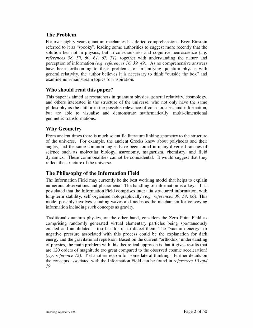
The Problem
For over eighty years quantum mechanics has defied comprehension. Even Einstein
referred to it as “spooky”, leading some authorities to suggest more recently that the solution lies not in physics, but in consciousness and cognitive neuroscience (e.g.
references 58, 59, 60, 61, 67, 71), together with understanding the nature and perception of information (e.g. references 16, 39, 49). As no comprehensive answers
have been forthcoming to these problems, or in unifying quantum physics with
general relativity, the author believes it is necessary to think “outside the box” and
examine non-mainstream topics for inspiration.
Who should read this paper?
This paper is aimed at researchers in quantum physics, general relativity, cosmology, and others interested in the structure of the universe, who not only have the same
philosophy as the author in the possible relevance of consciousness and information,
but are able to visualise and demonstrate mathematically, multi-dimensional
geometric transformations.
Why Geometry
From ancient times there is much scientific literature linking geometry to the structure of the universe. For example, the ancient Greeks knew about polyhedra and their
angles, and the same common angles have been found in many diverse branches of
science such as molecular biology, astronomy, magnetism, chemistry, and fluid
dynamics. These commonalities cannot be coincidental. It would suggest that they
reflect the structure of the universe.
The Philosophy of the Information Field
The Information Field may currently be the best working model that helps to explain
numerous observations and phenomena. The handling of information is a key. It is postulated that the Information Field comprises inter alia structured information, with
long-term stability, self organised holographically (e.g. references 39, 54, 66). This
model possibly involves standing waves and nodes as the mechanism for conveying
information including such concepts as gravity.
Traditional quantum physics, on the other hand, considers the Zero Point Field as
comprising randomly generated virtual elementary particles being spontaneously
created and annihilated – too fast for us to detect them. The “vacuum energy” or
negative pressure associated with this process could be the explanation for dark
energy and the gravitational repulsion. Based on the current “orthodox” understanding
of physics, the main problem with this theoretical approach is that it gives results that
are 120 orders of magnitude too great compared to the observed cosmic acceleration!
(e.g. reference 12). Yet another reason for some lateral thinking. Further details on
the concepts associated with the Information Field can be found in references 15 and
19.
Dowsing Geometry v28 Page 3 of 50
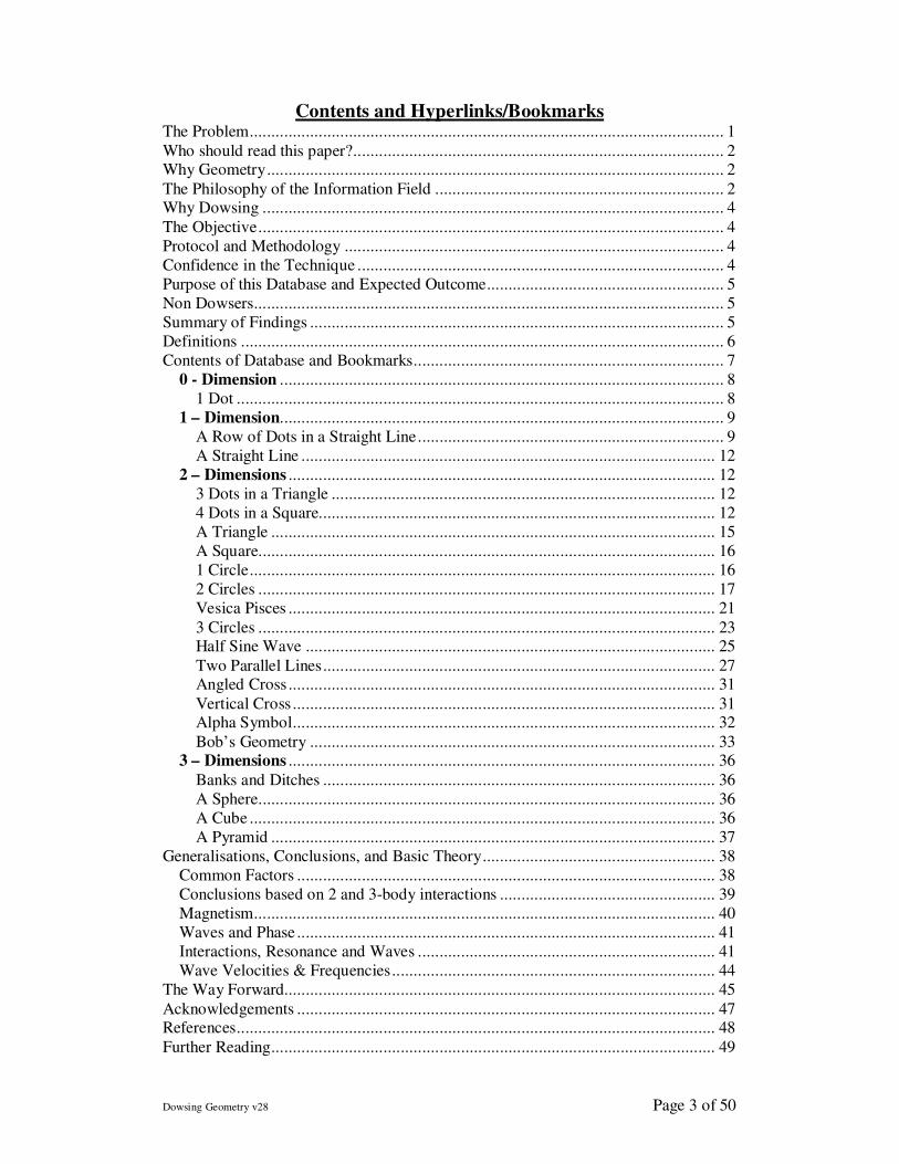
Contents and Hyperlinks/Bookmarks The Problem.............................................................................................................. 1
Who should read this paper?...................................................................................... 2 Why Geometry.......................................................................................................... 2
The Philosophy of the Information Field ................................................................... 2 Why Dowsing ........................................................................................................... 4
The Objective............................................................................................................ 4
Protocol and Methodology ........................................................................................ 4
Confidence in the Technique ..................................................................................... 4
Purpose of this Database and Expected Outcome....................................................... 5
Non Dowsers............................................................................................................. 5
Summary of Findings ................................................................................................ 5
Definitions ................................................................................................................ 6
Contents of Database and Bookmarks........................................................................ 7
0 - Dimension ....................................................................................................... 8
1 Dot ................................................................................................................. 8
1 – Dimension....................................................................................................... 9
A Row of Dots in a Straight Line....................................................................... 9
A Straight Line ................................................................................................ 12
2 – Dimensions ................................................................................................... 12
3 Dots in a Triangle ......................................................................................... 12
4 Dots in a Square............................................................................................ 12
A Triangle ....................................................................................................... 15
A Square.......................................................................................................... 16
1 Circle............................................................................................................ 16
2 Circles .......................................................................................................... 17
Vesica Pisces ................................................................................................... 21
3 Circles .......................................................................................................... 23 Half Sine Wave ............................................................................................... 25
Two Parallel Lines........................................................................................... 27 Angled Cross ................................................................................................... 31
Vertical Cross .................................................................................................. 31 Alpha Symbol.................................................................................................. 32
Bob’s Geometry .............................................................................................. 33 3 – Dimensions ................................................................................................... 36
Banks and Ditches ........................................................................................... 36
A Sphere.......................................................................................................... 36
A Cube ............................................................................................................ 36
A Pyramid ....................................................................................................... 37
Generalisations, Conclusions, and Basic Theory...................................................... 38
Common Factors ................................................................................................. 38
Conclusions based on 2 and 3-body interactions .................................................. 39
Magnetism........................................................................................................... 40
Waves and Phase ................................................................................................. 41
Interactions, Resonance and Waves ..................................................................... 41
Wave Velocities & Frequencies........................................................................... 44
The Way Forward.................................................................................................... 45
Acknowledgements ................................................................................................. 47 References............................................................................................................... 48
Further Reading....................................................................................................... 49
Dowsing Geometry v28 Page 4 of 50
Why Dowsing
Not only does dowsing strongly combine consciousness and information, but it has
been known for many years that in dowsing, geometry is fundamental. As a result of using dowsing as a scientific tool, numerous published papers have found the same
polyhedra and other universal angles, (such as references 10, 11, 13, 14). Experimental results, using sound scientific techniques for measurements and their
protocols, are starting to provide a significant input to the fundamental understanding of how dowsing works, and provide confidence in using this technique to explore the
structure of the universe. (see references 6, 7, 8, 17, 18).
Dowsing therefore seems an ideal technique to adopt in our quest to explore the
structure of the universe, as it is unique in combining some of the key components –
consciousness, information, and geometry.
The Objective
The ambitious objective of this paper is to investigate the structure of the Information Field, (and by implication the Universe), by dowsing pure geometry. This is unique
and different from the usual applications associated with dowsing. Over the last few
years, this technique has proved to be a very effective research tool. Ascertaining the
mathematics of transformations between physical source geometry and the neural
(sub) conscious patterns perceived when dowsing, could lead to clues as to how
nature’s information is stored and accessed: In other words “the structure of the
universe”.
Protocol and Methodology
The technique adopted is dowsing simple 0, 1, 2, and 3-dimensional geometric shapes
(e.g. dots, lines, circles, cubes, etc.) and measuring in 3-dimensions the different
dowsable patterns detected. Dowsing this pure geometry eliminates any effects or
perturbations of mass or matter. We are therefore only researching individual
consciousness, astronomical factors, and the Information Field.
Further general information on the protocol and methodology adopted, including
details of a specialised yardstick that has proved effective in dowsing measurements
can be found in reference 27.
Confidence in the Technique
Initial experimental results are very promising suggesting that a plethora of factors are
involved in producing certain types of dowsable lines and patterns. These include:-
1. photons, magnetism and gravity
2. the earth’s spin and several astronomical factors strongly influence dowsable
fields;
3. the act of observing two objects causes them to interact; and
4. dowsing a "n-dimensional" geometrical source produces, in some cases, the
same dowsable pattern as a "n+1 dimensional" geometric source. In other words, there are strong elements of comprehensiveness and universality
in this adopted technique.
Dowsing Geometry v28 Page 5 of 50
Developing an analogy to X-ray crystallography and diffraction gratings may also
prove useful in the quest to probe the structure of the Information Field. In this case
electro-magnetic fields are not being used, but consciousness. Confidence in this
approach is justified for several reasons. Some of the patterns observed when
dowsing, such as Figure 33, seem similar to those produced by diffraction gratings or
x-ray crystallography. But in particular, as a result of numerous experimental
observations, resonance, interference, null points, and 2:1 ratios have been observed. These examples suggest waves are involved in dowsing, and hence possible
diffraction patterns.
Purpose of this Database and Expected Outcome
In the following data base of different geometries, researchers are invited to find if
mathematical transformations exist that would explain relationships between the mind
generated geometric patterns observed by dowsing, and the physical source geometry
that creates those patterns. This should help demonstrate how dowsing, the universe,
and consciousness are connected, and the mechanisms involved. An analogy is to
Crick and Watson discovering the structure of DNA by using Rosalind Franklin’s
diffraction images.
This approach could also have the benefit of adding support, or otherwise, to the theory of the Information Field, including an understanding of how macro geometry is
mirrored in it, and support or disprove the theory that the Information Field, and our
universe, is a 5-dimensional hologram.
Non Dowsers
For newcomers to dowsing a brief explanation for the non dowser can be found in
references 1, 2, 15, 36.
As this database involves the measurements of auras, it is appropriate to explain that
an aura is a multi-layered subtle energy field surrounding any physical or abstract
object, and contains information about that object. Being perceived by the mind,
auras are created as a result of the object’s interaction with local space-time, and usually form a geometric pattern. See references 25 and 31.
Further Information This paper is only a summary. A general background can be found on the author’s
website www.jeffreykeen.co.uk
The full scientific paper with bookmarks and hyperlinks, containing all the figures,
graphs, tables, protocols, technical details, and mathematical support, can be found at
http://www.jeffreykeen.co.uk/Scientific%20Papers%20in%20Word/Dowsing%20Geo
metry%20v28.doc
Dowsing Geometry v28 Page 6 of 50
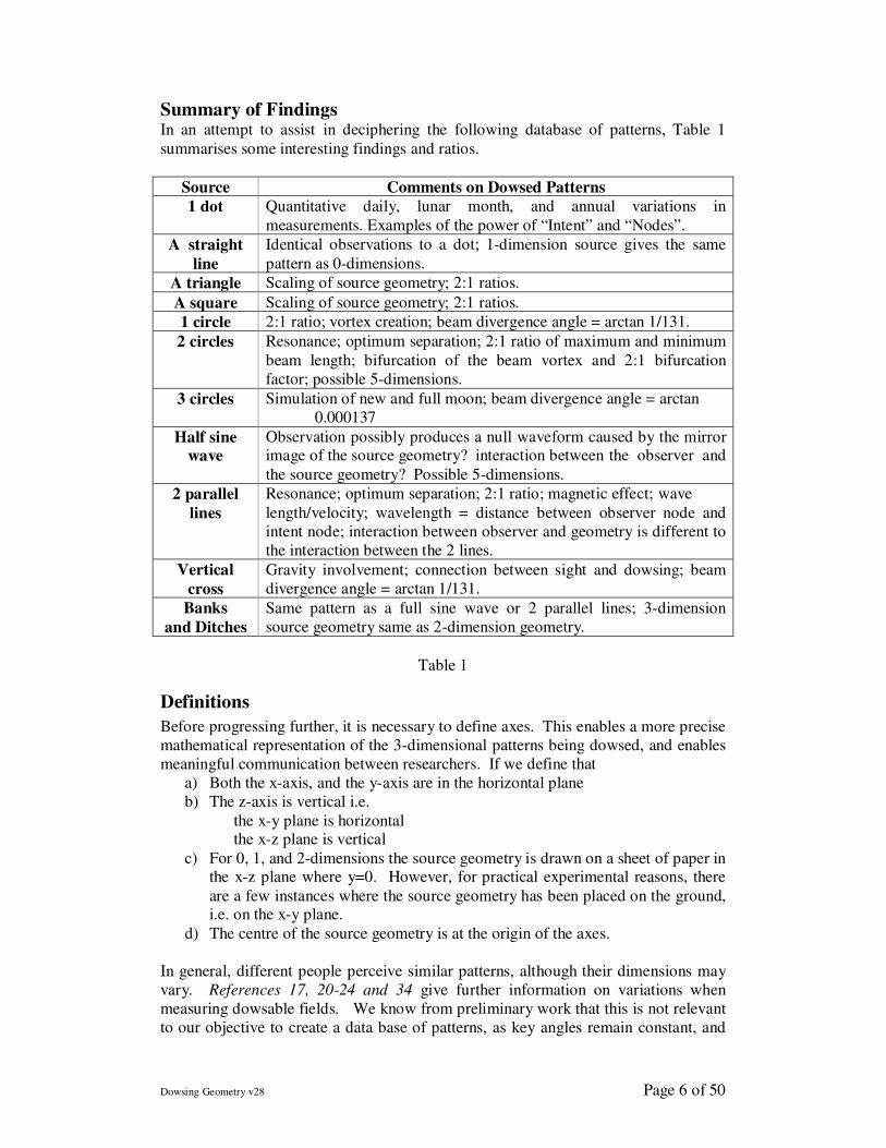
Summary of Findings In an attempt to assist in deciphering the following database of patterns, Table 1
summarises some interesting findings and ratios.
Source Comments on Dowsed Patterns
1 dot Quantitative daily, lunar month, and annual variations in
measurements. Examples of the power of “Intent” and “Nodes”.
A straight
line
Identical observations to a dot; 1-dimension source gives the same
pattern as 0-dimensions.
A triangle Scaling of source geometry; 2:1 ratios.
A square Scaling of source geometry; 2:1 ratios.
1 circle 2:1 ratio; vortex creation; beam divergence angle = arctan 1/131.
2 circles Resonance; optimum separation; 2:1 ratio of maximum and minimum
beam length; bifurcation of the beam vortex and 2:1 bifurcation
factor; possible 5-dimensions.
3 circles Simulation of new and full moon; beam divergence angle = arctan
0.000137
Half sine
wave
Observation possibly produces a null waveform caused by the mirror image of the source geometry? interaction between the observer and
the source geometry? Possible 5-dimensions.
2 parallel
lines
Resonance; optimum separation; 2:1 ratio; magnetic effect; wave
length/velocity; wavelength = distance between observer node and
intent node; interaction between observer and geometry is different to
the interaction between the 2 lines.
Vertical
cross
Gravity involvement; connection between sight and dowsing; beam
divergence angle = arctan 1/131.
Banks
and Ditches
Same pattern as a full sine wave or 2 parallel lines; 3-dimension
source geometry same as 2-dimension geometry.
Table 1
Definitions
Before progressing further, it is necessary to define axes. This enables a more precise
mathematical representation of the 3-dimensional patterns being dowsed, and enables
meaningful communication between researchers. If we define that
a) Both the x-axis, and the y-axis are in the horizontal plane
b) The z-axis is vertical i.e.
the x-y plane is horizontal the x-z plane is vertical
c) For 0, 1, and 2-dimensions the source geometry is drawn on a sheet of paper in the x-z plane where y=0. However, for practical experimental reasons, there
are a few instances where the source geometry has been placed on the ground, i.e. on the x-y plane.
d) The centre of the source geometry is at the origin of the axes.
In general, different people perceive similar patterns, although their dimensions may
vary. References 17, 20-24 and 34 give further information on variations when
measuring dowsable fields. We know from preliminary work that this is not relevant
to our objective to create a data base of patterns, as key angles remain constant, and
Dowsing Geometry v28 Page 7 of 50
the perceived patterns only differ in scale, with possible minor perturbations that do
not affect the overall observed geometry. Only the multiplying coefficients change in
the mathematical description; the overall relationships are similar.
Contents of Database and Bookmarks
0 - Dimension
Source Geometry Description of Source
. 1 Dot
1 – Dimension
Source Geometry Description of Source
. . . . . . . A row of dots in a straight line
1 straight line
2 – Dimensions
Source Geometry Description of Source
.
. . 3 dots in a triangle
. .
. . 4 dots in a square
Triangle
Square
Circle
2 Circles
Vesica Pices
3 Circles
½ sine wave
2 Lines
Angled Cross
Vertical Cross
Alpha symbol
Bob’s Geometry
3 – Dimensions
Source Geometry Description of Source
Banks and Ditches
Sphere
Cube
Pyramid
Dowsing Geometry v28 Page 8 of 50
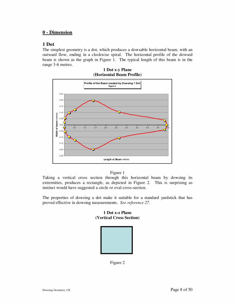
0 - Dimension
1 Dot The simplest geometry is a dot, which produces a dowsable horizontal beam, with an outward flow, ending in a clockwise spiral. The horizontal profile of the dowsed
beam is shown as the graph in Figure 1. The typical length of this beam is in the range 3-6 metres.
1 Dot x-y Plane
(Horizontal Beam Profile)
Figure 1 Taking a vertical cross section through this horizontal beam by dowsing its
extremities, produces a rectangle, as depicted in Figure 2. This is surprising as
instinct would have suggested a circle or oval cross-section.
The properties of dowsing a dot make it suitable for a standard yardstick that has
proved effective in dowsing measurements. See reference 27.
1 Dot x-z Plane
(Vertical Cross Section)
Figure 2
Profile of the Beam created by Dowsing 1 DotFigure 2
-0 .25
-0 .20
-0 .15
-0 .10
-0 .05
0 .00
0 .05
0 .10
0 .15
0 .20
0 .25
0.0 0.5 1.0 1.5 2.0 2.5 3.0 3.5 4.0 4.5 5.0
Length of Beam metres
Wid
th o
f b
ea
m m
etr
es
Dowsing Geometry v28 Page 9 of 50
1 – Dimension
A Row of Dots in a Straight Line
Dots in a straight line are analogous to a diffraction grating. As the number of dots increases, the width and length of the horizontal dowsable field, emanating from the
dots, changes.
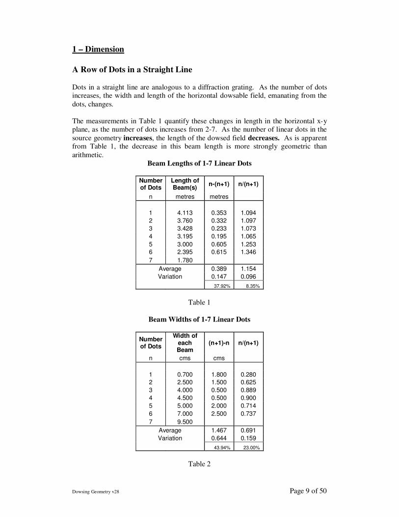
The measurements in Table 1 quantify these changes in length in the horizontal x-y plane, as the number of dots increases from 2-7. As the number of linear dots in the
source geometry increases, the length of the dowsed field decreases. As is apparent from Table 1, the decrease in this beam length is more strongly geometric than
arithmetic.
Beam Lengths of 1-7 Linear Dots
Number of Dots
Length of Beam(s)
n-(n+1) n/(n+1)
n metres metres
1 4.113 0.353 1.094
2 3.760 0.332 1.097
3 3.428 0.233 1.073
4 3.195 0.195 1.065
5 3.000 0.605 1.253
6 2.395 0.615 1.346
7 1.780
Average 0.389 1.154
Variation 0.147 0.096
37.92% 8.35%
Table 1
Beam Widths of 1-7 Linear Dots
Number of Dots
Width of each Beam
(n+1)-n n/(n+1)
n cms cms
1 0.700 1.800 0.280
2 2.500 1.500 0.625
3 4.000 0.500 0.889
4 4.500 0.500 0.900
5 5.000 2.000 0.714
6 7.000 2.500 0.737
7 9.500
Average 1.467 0.691
Variation 0.644 0.159
43.94% 23.00%
Table 2
Dowsing Geometry v28 Page 10 of 50
The measurements in Table 2 are also in the horizontal x-y plane, but quantify the
change in width of the dowsed field as the number of dots increases from 2 to 7. At
the same distance from the source, as the number of linear dots increases, the beam
width also increases. This increase in width is neither strongly arithmetic nor
geometric. There may be an analogy to diffraction gratings as more slits produce a
wider area of interference fringes.
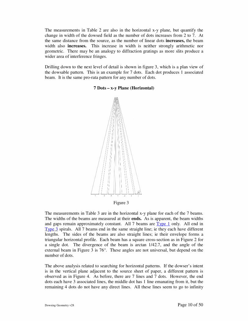
Drilling down to the next level of detail is shown in figure 3, which is a plan view of
the dowsable pattern. This is an example for 7 dots. Each dot produces 1 associated beam. It is the same pro-rata pattern for any number of dots.
7 Dots – x-y Plane (Horizontal)
Figure 3
The measurements in Table 3 are in the horizontal x-y plane for each of the 7 beams.
The widths of the beams are measured at their ends. As is apparent, the beam widths and gaps remain approximately constant. All 7 beams are Type 1 only. All end in
Type 3 spirals. All 7 beams end in the same straight line; ie they each have different lengths. The sides of the beams are also straight lines; ie their envelope forms a
triangular horizontal profile. Each beam has a square cross-section as in Figure 2 for a single dot. The divergence of the beam is arctan 1/42.7, and the angle of the
external beam in Figure 3 is 76°. These angles are not universal, but depend on the
number of dots.
The above analysis related to searching for horizontal patterns. If the dowser’s intent
is in the vertical plane adjacent to the source sheet of paper, a different pattern is
observed as in Figure 4. As before, there are 7 lines and 7 dots. However, the end
dots each have 3 associated lines, the middle dot has 1 line emanating from it, but the
remaining 4 dots do not have any direct lines. All these lines seem to go to infinity
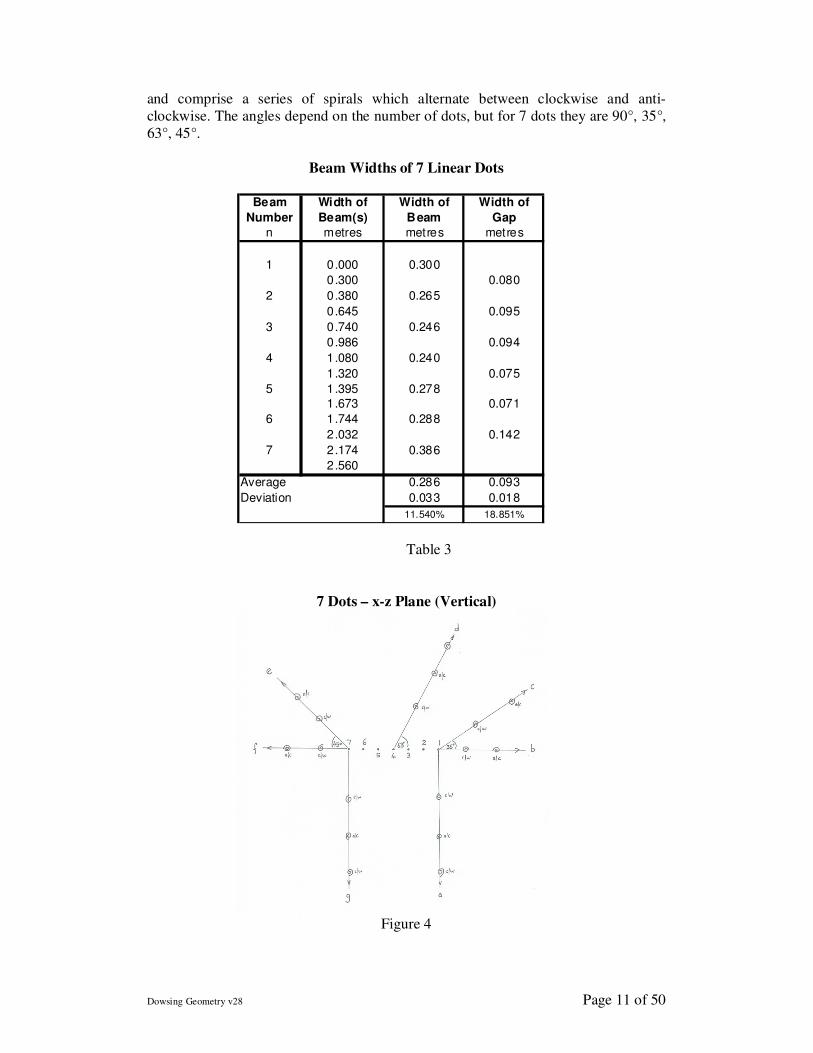
Dowsing Geometry v28 Page 11 of 50
and comprise a series of spirals which alternate between clockwise and anti-
clockwise. The angles depend on the number of dots, but for 7 dots they are 90°, 35°,
63°, 45°.
Beam Widths of 7 Linear Dots
Table 3
7 Dots – x-z Plane (Vertical)
Figure 4
Beam
Number
Width of
Beam(s)
Width of
Beam
Width of
Gap
n metres metres metres
1 0.000 0.300
0.300 0.080
2 0.380 0.265
0.645 0.095
3 0.740 0.246
0.986 0.094
4 1.080 0.240
1.320 0.075
5 1.395 0.278
1.673 0.071
6 1.744 0.288
2.032 0.142
7 2.174 0.386
2.560
Average 0.286 0.093
Deviation 0.033 0.018
11.540% 18.851%
Dowsing Geometry v28 Page 12 of 50
Most inanimate objects as well as living animals or plants have 7 linear chakras.
Seven linear dots were chosen to see if there was any geometric connection to the 7
chakras, and to the aura and tree of life patterns generated by these chakras. With this
objective in mind, the above experiments were repeated with the 7 dots positioned
vertically as well as 7 vertical circles. The same patterns as above were found,
suggesting rotational symmetry. Unfortunately, Figures 3 and 4 do not suggest any
obvious connection to auras, Type 2 lines, or the tree of life patterns (see reference
14) – as usually associated with dowsing life forms. Consequently, it may be deduced
that matter as well as pure geometry may be involved in producing chakra patterns.
A Straight Line A straight line drawn on a horizontal sheet of paper dowses as 9 “reflections” on both
sides of the source line, and in the horizontal plane through the source line. However,
a physical line, such as a pencil, only has 7 similar “reflections”. For both abstract
and physical lines of about 15 cms length, the separation distances between adjacent
reflections is about 1-2 cms.
The centre point of a straight abstract or physical line also emits a perpendicular
dowsable vortex beam. Interestingly, it is found that the same results are obtained
irrespective of the length of the source line. Taken to the limit the beam pattern
observed is identical to dowsing 1 dot as discussed earlier. Ignoring the above
reflections, there would seem no difference between dowsing a dot or a line!
2 – Dimensions
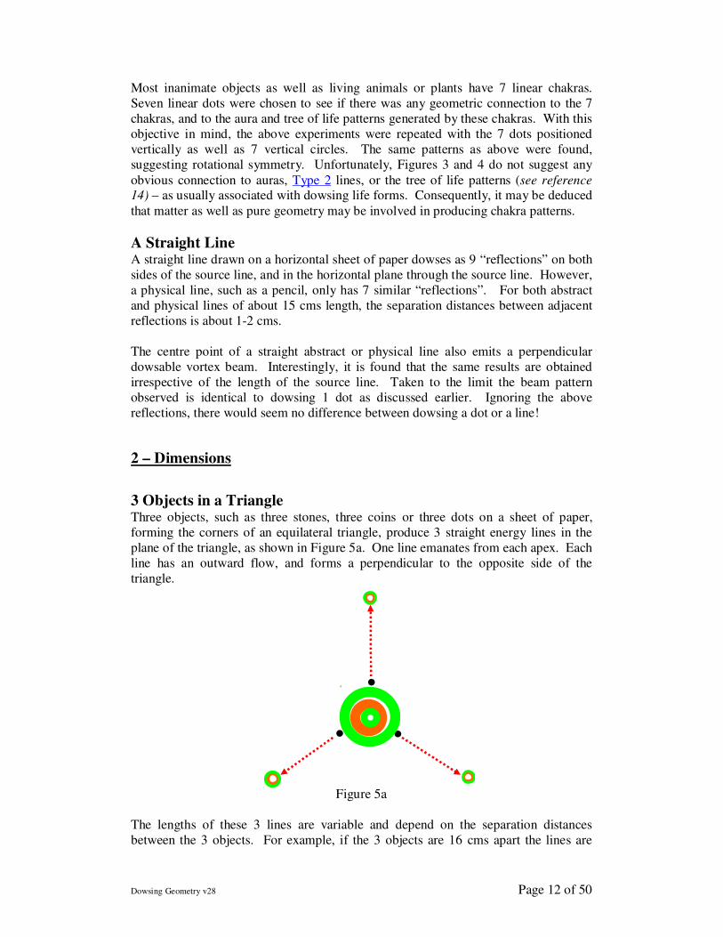
3 Objects in a Triangle Three objects, such as three stones, three coins or three dots on a sheet of paper,
forming the corners of an equilateral triangle, produce 3 straight energy lines in the
plane of the triangle, as shown in Figure 5a. One line emanates from each apex. Each
line has an outward flow, and forms a perpendicular to the opposite side of the
triangle.
Figure 5a
The lengths of these 3 lines are variable and depend on the separation distances
between the 3 objects. For example, if the 3 objects are 16 cms apart the lines are
.
. .
Dowsing Geometry v28 Page 13 of 50
about 500 metres long, but if the 3 objects are barely touching, the lines extend only
about one metre. These three lines dowsed white on a Mager disc, and can be
classified as Type 1 subtle energy. The usual Type 3 double spiral terminates these
lines, and gives a green indication on a Mager disc. As explained in the section
covering 2-body interaction, these spirals bifurcate.
Perpendicular to the paper is a central upward clockwise conical helix, the base of which is approximately circular and passes through the 3 objects. As usual, this
central structure comprises 7 pairs of inverted cones and is about 3 metres high. It can be classified as Type 3 subtle energy, and dowses green on a Mager disk. It does
not bifurcate.
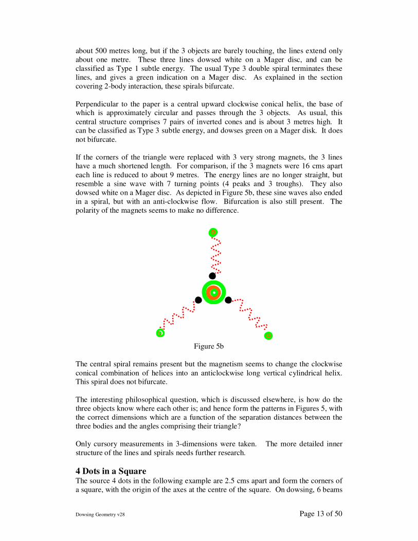
If the corners of the triangle were replaced with 3 very strong magnets, the 3 lines have a much shortened length. For comparison, if the 3 magnets were 16 cms apart
each line is reduced to about 9 metres. The energy lines are no longer straight, but
resemble a sine wave with 7 turning points (4 peaks and 3 troughs). They also
dowsed white on a Mager disc. As depicted in Figure 5b, these sine waves also ended
in a spiral, but with an anti-clockwise flow. Bifurcation is also still present. The
polarity of the magnets seems to make no difference.
Figure 5b
The central spiral remains present but the magnetism seems to change the clockwise
conical combination of helices into an anticlockwise long vertical cylindrical helix. This spiral does not bifurcate.
The interesting philosophical question, which is discussed elsewhere, is how do the
three objects know where each other is; and hence form the patterns in Figures 5, with
the correct dimensions which are a function of the separation distances between the
three bodies and the angles comprising their triangle?
Only cursory measurements in 3-dimensions were taken. The more detailed inner
structure of the lines and spirals needs further research.
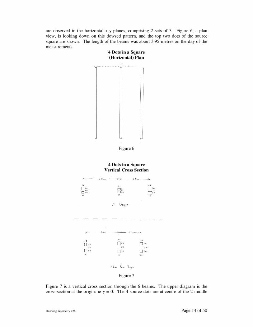
4 Dots in a Square The source 4 dots in the following example are 2.5 cms apart and form the corners of
a square, with the origin of the axes at the centre of the square. On dowsing, 6 beams
.
Dowsing Geometry v28 Page 14 of 50
are observed in the horizontal x-y planes, comprising 2 sets of 3. Figure 6, a plan
view, is looking down on this dowsed pattern, and the top two dots of the source
square are shown. The length of the beams was about 3.95 metres on the day of the
measurements.
4 Dots in a Square
(Horizontal) Plan
Figure 6
4 Dots in a Square
Vertical Cross Section
Figure 7
Figure 7 is a vertical cross section through the 6 beams. The upper diagram is the cross-section at the origin: ie y = 0. The 4 source dots are at centre of the 2 middle
Dowsing Geometry v28 Page 15 of 50
beams. The bottom cross section was taken 2.6 metres from origin: ie y = 2.6. As is
apparent, on moving away from the origin, the top 3 beams diverge from the lower 3
beams. At y = 2.6m the separation between the top and bottom 3 beams increases by
2.25 – 7.7 times, and the right hand side beams seem to curve towards the centre
beam by 28%.
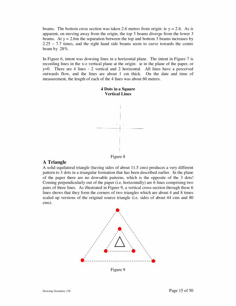
In Figure 6, intent was dowsing lines in a horizontal plane. The intent in Figure 7 is recording lines in the x-z vertical plane at the origin: ie in the plane of the paper, or
y=0. There are 4 lines - 2 vertical and 2 horizontal. All lines have a perceived outwards flow, and the lines are about 1 cm thick. On the date and time of
measurement, the length of each of the 4 lines was about 60 metres.
4 Dots in a Square
Vertical Lines
Figure 8
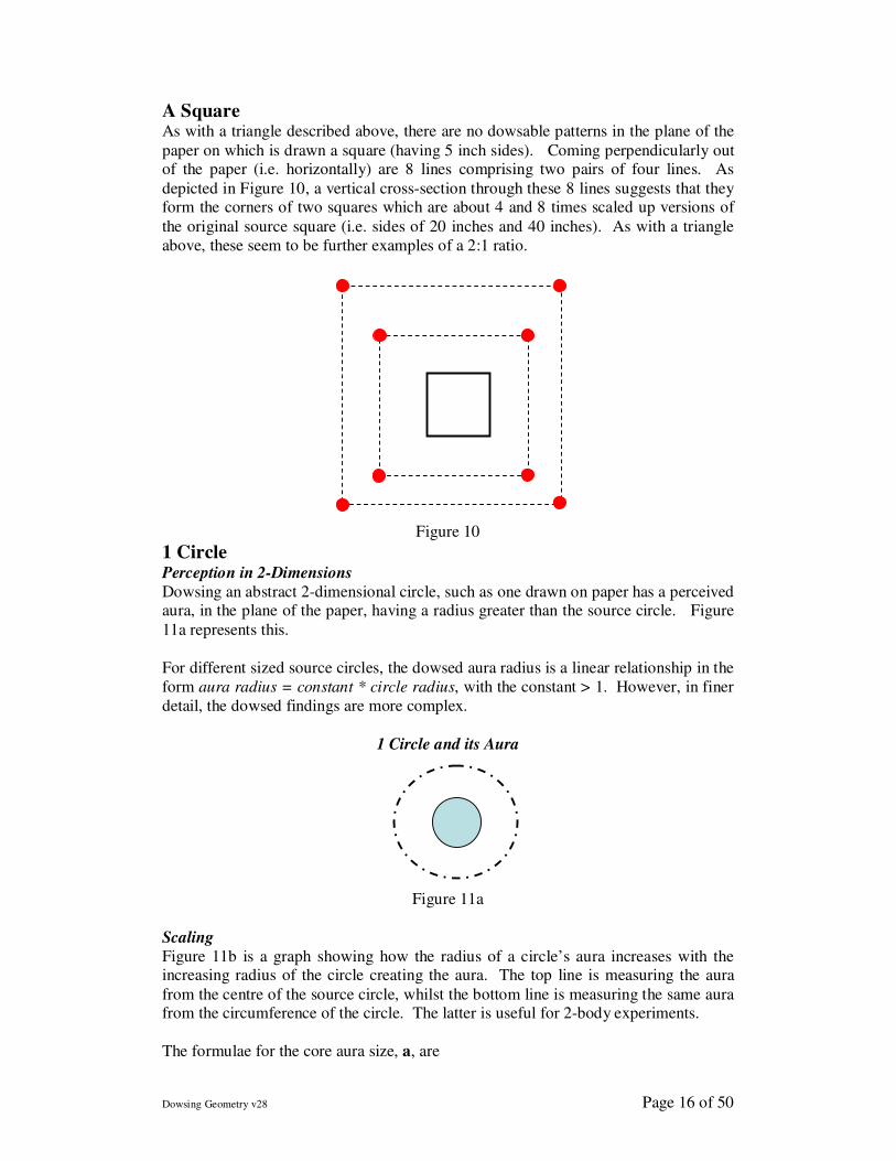
A Triangle A solid equilateral triangle (having sides of about 11.5 cms) produces a very different pattern to 3 dots in a triangular formation that has been described earlier. In the plane
of the paper there are no dowsable patterns, which is the opposite of the 3 dots! Coming perpendicularly out of the paper (i.e. horizontally) are 6 lines comprising two
pairs of three lines. As illustrated in Figure 9, a vertical cross-section through these 6
lines shows that they form the corners of two triangles which are about 4 and 8 times
scaled up versions of the original source triangle (i.e. sides of about 44 cms and 80
cms).
Figure 9
Dowsing Geometry v28 Page 16 of 50
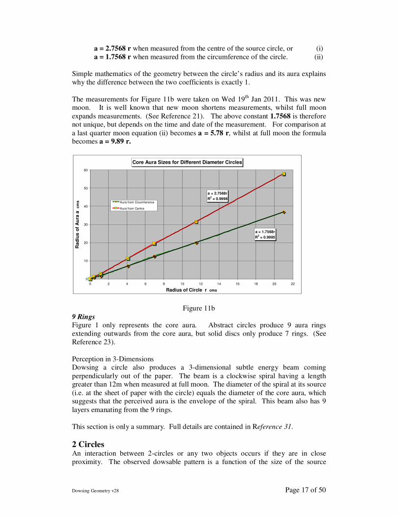
A Square As with a triangle described above, there are no dowsable patterns in the plane of the
paper on which is drawn a square (having 5 inch sides). Coming perpendicularly out of the paper (i.e. horizontally) are 8 lines comprising two pairs of four lines. As
depicted in Figure 10, a vertical cross-section through these 8 lines suggests that they form the corners of two squares which are about 4 and 8 times scaled up versions of
the original source square (i.e. sides of 20 inches and 40 inches). As with a triangle
above, these seem to be further examples of a 2:1 ratio.
Figure 10
1 Circle Perception in 2-Dimensions
Dowsing an abstract 2-dimensional circle, such as one drawn on paper has a perceived aura, in the plane of the paper, having a radius greater than the source circle. Figure
11a represents this.
For different sized source circles, the dowsed aura radius is a linear relationship in the
form aura radius = constant * circle radius, with the constant > 1. However, in finer
detail, the dowsed findings are more complex.
1 Circle and its Aura
Figure 11a
Scaling
Figure 11b is a graph showing how the radius of a circle’s aura increases with the increasing radius of the circle creating the aura. The top line is measuring the aura
from the centre of the source circle, whilst the bottom line is measuring the same aura from the circumference of the circle. The latter is useful for 2-body experiments.
The formulae for the core aura size, a, are
Dowsing Geometry v28 Page 17 of 50
a = 2.7568 r when measured from the centre of the source circle, or (i)
a = 1.7568 r when measured from the circumference of the circle. (ii)
Simple mathematics of the geometry between the circle’s radius and its aura explains
why the difference between the two coefficients is exactly 1.
The measurements for Figure 11b were taken on Wed 19th
Jan 2011. This was new moon. It is well known that new moon shortens measurements, whilst full moon
expands measurements. (See Reference 21). The above constant 1.7568 is therefore not unique, but depends on the time and date of the measurement. For comparison at
a last quarter moon equation (ii) becomes a = 5.78 r, whilst at full moon the formula becomes a = 9.89 r.
Core Aura Sizes for Different Diameter Circles
a = 1.7568r
R2 = 0.9995
a = 2.7568r
R2 = 0.9998
0
10
20
30
40
50
60
0 2 4 6 8 10 12 14 16 18 20 22
Radius of Circle r cms
Ra
diu
s o
f A
ura
a
cm
s Aura from Cicumference
Aura from Centre
Figure 11b
9 Rings Figure 1 only represents the core aura. Abstract circles produce 9 aura rings
extending outwards from the core aura, but solid discs only produce 7 rings. (See
Reference 23).
Perception in 3-Dimensions Dowsing a circle also produces a 3-dimensional subtle energy beam coming
perpendicularly out of the paper. The beam is a clockwise spiral having a length greater than 12m when measured at full moon. The diameter of the spiral at its source
(i.e. at the sheet of paper with the circle) equals the diameter of the core aura, which suggests that the perceived aura is the envelope of the spiral. This beam also has 9
layers emanating from the 9 rings.
This section is only a summary. Full details are contained in Reference 31.
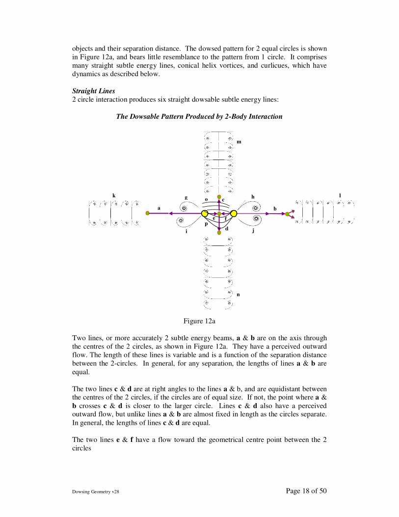
2 Circles An interaction between 2-circles or any two objects occurs if they are in close
proximity. The observed dowsable pattern is a function of the size of the source
Dowsing Geometry v28 Page 18 of 50
objects and their separation distance. The dowsed pattern for 2 equal circles is shown
in Figure 12a, and bears little resemblance to the pattern from 1 circle. It comprises
many straight subtle energy lines, conical helix vortices, and curlicues, which have
dynamics as described below.
Straight Lines
2 circle interaction produces six straight dowsable subtle energy lines:
The Dowsable Pattern Produced by 2-Body Interaction
Figure 12a
Two lines, or more accurately 2 subtle energy beams, a & b are on the axis through
the centres of the 2 circles, as shown in Figure 12a. They have a perceived outward
flow. The length of these lines is variable and is a function of the separation distance
between the 2-circles. In general, for any separation, the lengths of lines a & b are
equal.
The two lines c & d are at right angles to the lines a & b, and are equidistant between the centres of the 2 circles, if the circles are of equal size. If not, the point where a &
b crosses c & d is closer to the larger circle. Lines c & d also have a perceived outward flow, but unlike lines a & b are almost fixed in length as the circles separate.
In general, the lengths of lines c & d are equal.
The two lines e & f have a flow toward the geometrical centre point between the 2
circles
a
e f
c
d
b
g hk
n
l
m
i j
o
p
Dowsing Geometry v28 Page 19 of 50
Curved Lines
Also depicted in Figure 12a, are 3 types of curved lines.
12 of these curved lines marked g, h, i & j comprise 4 sets of curlicues emanating
outwards from the 2 circles. Each set comprises 3 curved lines flowing away from
the 2 circles, on either side of the straight central axis. The lengths of these curved
lines are less than the straight lines ab and cd. (However, due to lack of space, the
diagram is incorrect here as it shows only 4 of the 12 lines emanating from the 2
circles).
Between the 2 circles, 6 curved lines, marked o & p, emanate inwards and join the 2 circles. These look similar to a magnetic lines of force pattern. They consist of 2 pairs
each comprising 3 curved lines either side of the central axis.
These curlicues are analogous to Cornu Spirals which are well known in optics and
occur when studying interference patterns and diffraction. Lines ab and cd seem to
act as mirrors so the observed patterns are symmetrical about these lines.
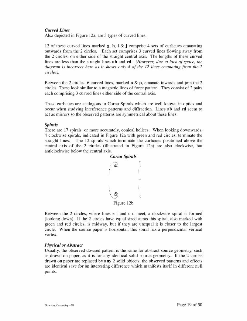
Spirals There are 17 spirals, or more accurately, conical helices. When looking downwards,
4 clockwise spirals, indicated in Figure 12a with green and red circles, terminate the
straight lines. The 12 spirals which terminate the curlicues positioned above the
central axis of the 2 circles (illustrated in Figure 12a) are also clockwise, but
anticlockwise below the central axis.
Cornu Spirals
Figure 12b
Between the 2 circles, where lines e f and c d meet, a clockwise spiral is formed
(looking down). If the 2 circles have equal sized auras this spiral, also marked with
green and red circles, is midway, but if they are unequal it is closer to the largest
circle. When the source paper is horizontal, this spiral has a perpendicular vertical vortex.
Physical or Abstract
Usually, the observed dowsed pattern is the same for abstract source geometry, such as drawn on paper, as it is for any identical solid source geometry. If the 2 circles
drawn on paper are replaced by any 2 solid objects, the observed patterns and effects are identical save for an interesting difference which manifests itself in different null
points.
Dowsing Geometry v28 Page 20 of 50
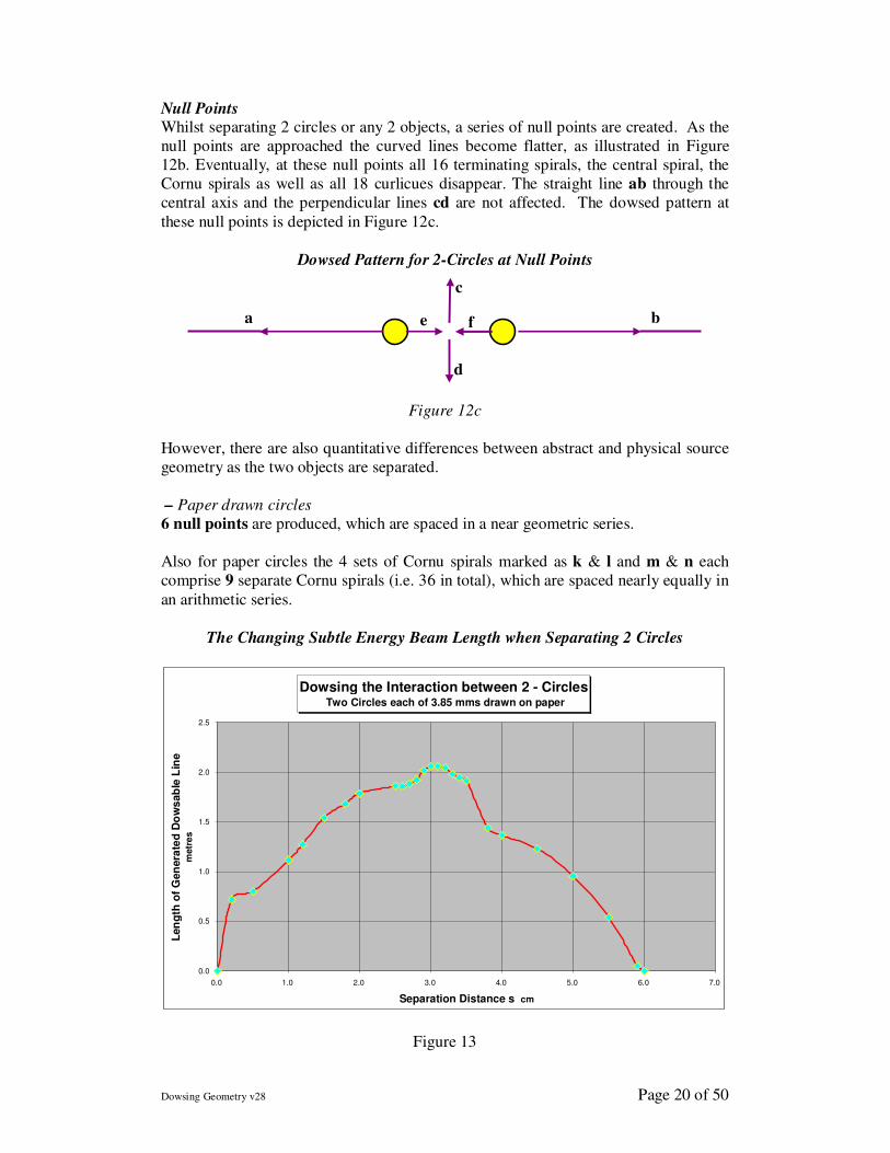
Null Points Whilst separating 2 circles or any 2 objects, a series of null points are created. As the
null points are approached the curved lines become flatter, as illustrated in Figure
12b. Eventually, at these null points all 16 terminating spirals, the central spiral, the
Cornu spirals as well as all 18 curlicues disappear. The straight line ab through the
central axis and the perpendicular lines cd are not affected. The dowsed pattern at
these null points is depicted in Figure 12c.
Dowsed Pattern for 2-Circles at Null Points
Figure 12c
However, there are also quantitative differences between abstract and physical source
geometry as the two objects are separated.
– Paper drawn circles
6 null points are produced, which are spaced in a near geometric series.
Also for paper circles the 4 sets of Cornu spirals marked as k & l and m & n each
comprise 9 separate Cornu spirals (i.e. 36 in total), which are spaced nearly equally in
an arithmetic series.
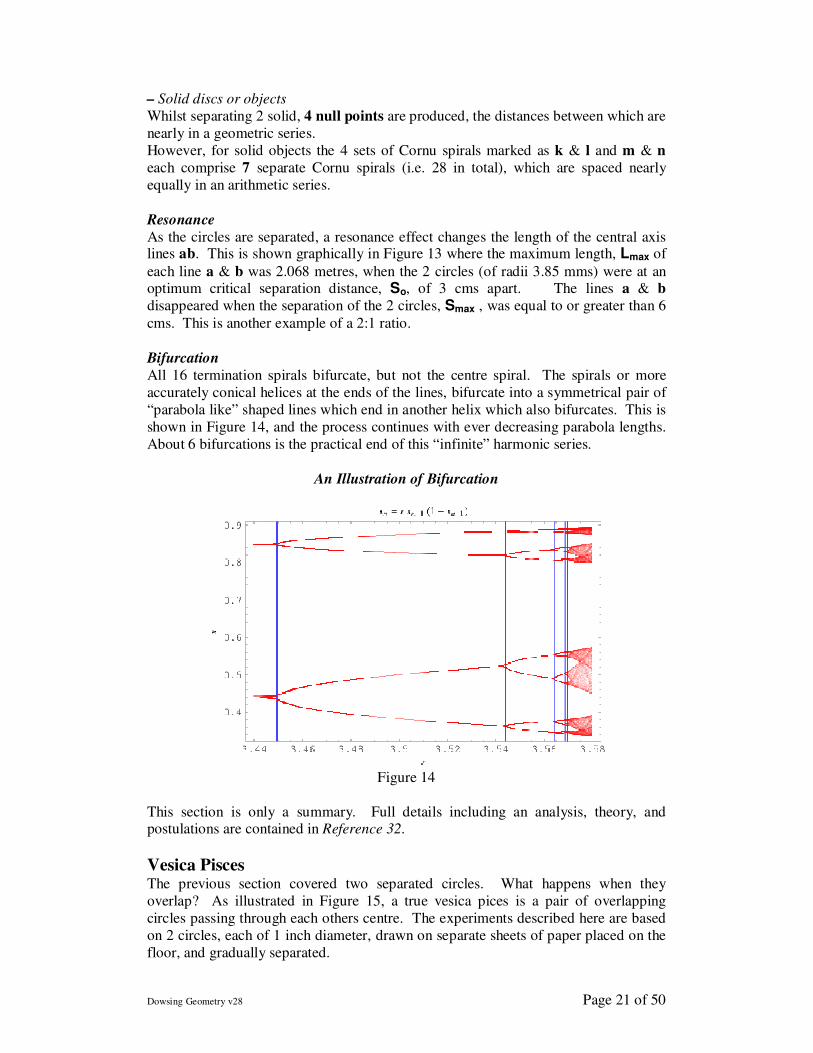
The Changing Subtle Energy Beam Length when Separating 2 Circles
Dowsing the Interaction between 2 - Circles Two Circles each of 3.85 mms drawn on paper
0.0
0.5
1.0
1.5
2.0
2.5
0.0 1.0 2.0 3.0 4.0 5.0 6.0 7.0
Separation Distance s cm
Len
gth
of
Gen
era
ted
Do
ws
ab
le L
ine
metr
es
Figure 13
a b
d
c
e f
Dowsing Geometry v28 Page 21 of 50
– Solid discs or objects
Whilst separating 2 solid, 4 null points are produced, the distances between which are
nearly in a geometric series.
However, for solid objects the 4 sets of Cornu spirals marked as k & l and m & n
each comprise 7 separate Cornu spirals (i.e. 28 in total), which are spaced nearly
equally in an arithmetic series.
Resonance
As the circles are separated, a resonance effect changes the length of the central axis lines ab. This is shown graphically in Figure 13 where the maximum length, Lmax of
each line a & b was 2.068 metres, when the 2 circles (of radii 3.85 mms) were at an optimum critical separation distance, So, of 3 cms apart. The lines a & b
disappeared when the separation of the 2 circles, Smax , was equal to or greater than 6
cms. This is another example of a 2:1 ratio.
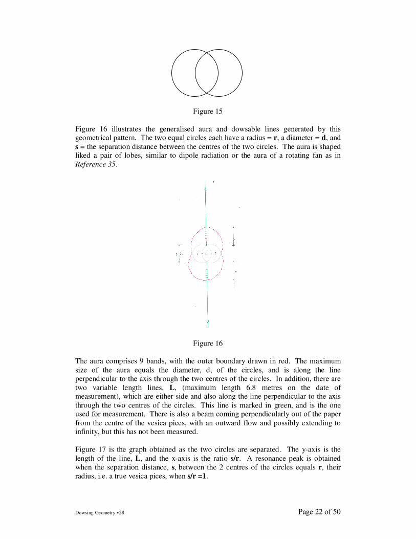
Bifurcation
All 16 termination spirals bifurcate, but not the centre spiral. The spirals or more
accurately conical helices at the ends of the lines, bifurcate into a symmetrical pair of
“parabola like” shaped lines which end in another helix which also bifurcates. This is
shown in Figure 14, and the process continues with ever decreasing parabola lengths.
About 6 bifurcations is the practical end of this “infinite” harmonic series.
An Illustration of Bifurcation
Figure 14
This section is only a summary. Full details including an analysis, theory, and postulations are contained in Reference 32.
Vesica Pisces The previous section covered two separated circles. What happens when they
overlap? As illustrated in Figure 15, a true vesica pices is a pair of overlapping
circles passing through each others centre. The experiments described here are based
on 2 circles, each of 1 inch diameter, drawn on separate sheets of paper placed on the
floor, and gradually separated.
Dowsing Geometry v28 Page 22 of 50
Figure 15
Figure 16 illustrates the generalised aura and dowsable lines generated by this geometrical pattern. The two equal circles each have a radius = r, a diameter = d, and
s = the separation distance between the centres of the two circles. The aura is shaped liked a pair of lobes, similar to dipole radiation or the aura of a rotating fan as in
Reference 35.
Figure 16
The aura comprises 9 bands, with the outer boundary drawn in red. The maximum
size of the aura equals the diameter, d, of the circles, and is along the line perpendicular to the axis through the two centres of the circles. In addition, there are
two variable length lines, L, (maximum length 6.8 metres on the date of measurement), which are either side and also along the line perpendicular to the axis
through the two centres of the circles. This line is marked in green, and is the one used for measurement. There is also a beam coming perpendicularly out of the paper
from the centre of the vesica pices, with an outward flow and possibly extending to infinity, but this has not been measured.
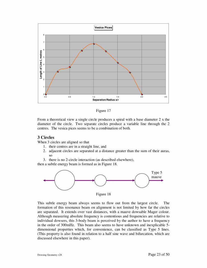
Figure 17 is the graph obtained as the two circles are separated. The y-axis is the
length of the line, L, and the x-axis is the ratio s/r. A resonance peak is obtained
when the separation distance, s, between the 2 centres of the circles equals r, their
radius, i.e. a true vesica pices, when s/r =1.
Dowsing Geometry v28 Page 23 of 50
Vesica Pices
0
1
2
3
4
5
6
7
8
0.0 0.5 1.0 1.5 2.0 2.5
Separation/Radius s/r
Len
gth
of
Lin
e L
metr
es
Figure 17
From a theoretical view a single circle produces a spiral with a base diameter 2 x the
diameter of the circle. Two separate circles produce a variable line through the 2
centres. The vesica pices seems to be a combination of both.
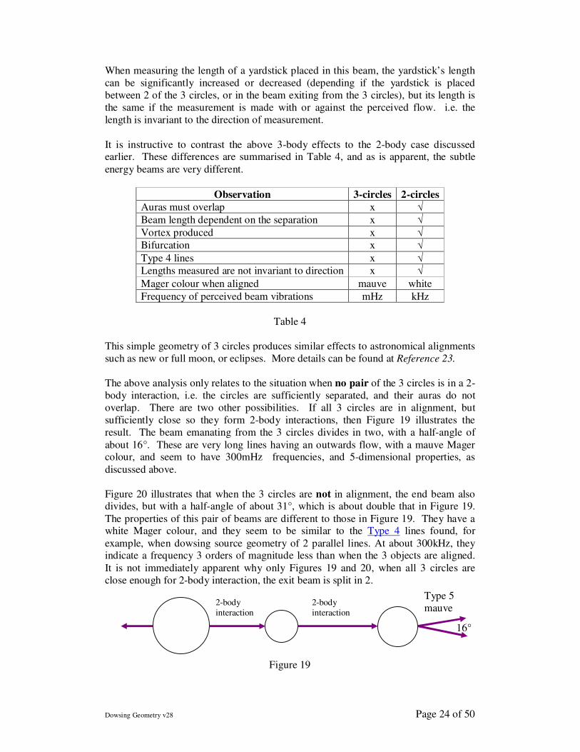
3 Circles When 3 circles are aligned so that
1. their centres are in a straight line, and
2. adjacent circles are separated at a distance greater than the sum of their auras,
so
3. there is no 2-circle interaction (as described elsewhere), then a subtle energy beam is formed as in Figure 18.
Figure 18
This subtle energy beam always seems to flow out from the largest circle. The
formation of this resonance beam on alignment is not limited by how far the circles
are separated. It extends over vast distances, with a mauve dowsable Mager colour.
Although measuring absolute frequency is contentious and frequencies are relative to
individual dowsers, this 3-body beam is perceived by the author to have a frequency
in the order of 300mHz. This beam also seems to have unknown and inexplicable 5-
dimensional properties which, for convenience, can be classified as Type 5 lines.
(This property is also found in relation to a half sine wave and bifurcation, which are
discussed elsewhere in this paper).
Type 5
mauve
Dowsing Geometry v28 Page 24 of 50
When measuring the length of a yardstick placed in this beam, the yardstick’s length
can be significantly increased or decreased (depending if the yardstick is placed
between 2 of the 3 circles, or in the beam exiting from the 3 circles), but its length is
the same if the measurement is made with or against the perceived flow. i.e. the
length is invariant to the direction of measurement.
It is instructive to contrast the above 3-body effects to the 2-body case discussed earlier. These differences are summarised in Table 4, and as is apparent, the subtle
energy beams are very different.
Observation 3-circles 2-circles
Auras must overlap x √
Beam length dependent on the separation x √
Vortex produced x √
Bifurcation x √
Type 4 lines x √
Lengths measured are not invariant to direction x √
Mager colour when aligned mauve white
Frequency of perceived beam vibrations mHz kHz
Table 4
This simple geometry of 3 circles produces similar effects to astronomical alignments
such as new or full moon, or eclipses. More details can be found at Reference 23.
The above analysis only relates to the situation when no pair of the 3 circles is in a 2-
body interaction, i.e. the circles are sufficiently separated, and their auras do not
overlap. There are two other possibilities. If all 3 circles are in alignment, but
sufficiently close so they form 2-body interactions, then Figure 19 illustrates the
result. The beam emanating from the 3 circles divides in two, with a half-angle of
about 16°. These are very long lines having an outwards flow, with a mauve Mager colour, and seem to have 300mHz frequencies, and 5-dimensional properties, as
discussed above.
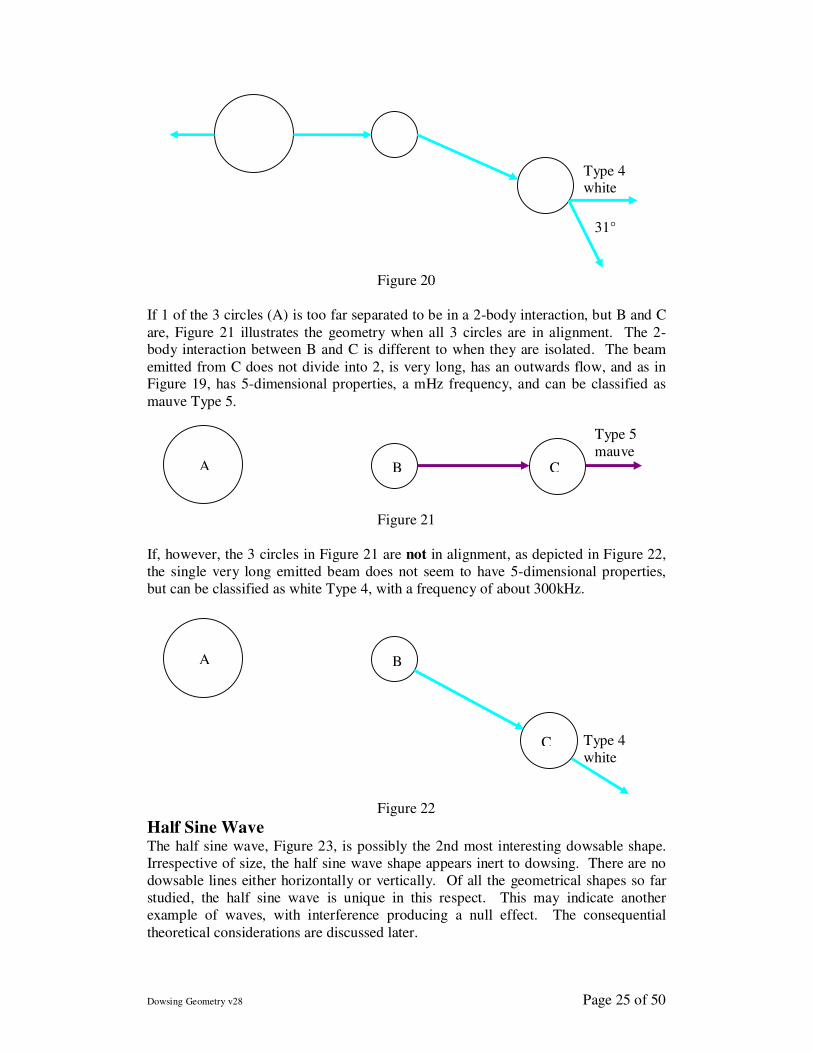
Figure 20 illustrates that when the 3 circles are not in alignment, the end beam also divides, but with a half-angle of about 31°, which is about double that in Figure 19.
The properties of this pair of beams are different to those in Figure 19. They have a white Mager colour, and they seem to be similar to the Type 4 lines found, for
example, when dowsing source geometry of 2 parallel lines. At about 300kHz, they indicate a frequency 3 orders of magnitude less than when the 3 objects are aligned.
It is not immediately apparent why only Figures 19 and 20, when all 3 circles are
close enough for 2-body interaction, the exit beam is split in 2.
Figure 19
Type 5
mauve
2-body
interaction
2-body
interaction
16°
Dowsing Geometry v28 Page 25 of 50
Figure 20
If 1 of the 3 circles (A) is too far separated to be in a 2-body interaction, but B and C
are, Figure 21 illustrates the geometry when all 3 circles are in alignment. The 2-body interaction between B and C is different to when they are isolated. The beam
emitted from C does not divide into 2, is very long, has an outwards flow, and as in Figure 19, has 5-dimensional properties, a mHz frequency, and can be classified as
mauve Type 5.
Figure 21
If, however, the 3 circles in Figure 21 are not in alignment, as depicted in Figure 22,
the single very long emitted beam does not seem to have 5-dimensional properties,
but can be classified as white Type 4, with a frequency of about 300kHz.
Figure 22
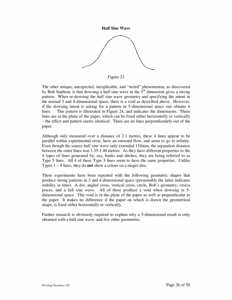
Half Sine Wave The half sine wave, Figure 23, is possibly the 2nd most interesting dowsable shape.
Irrespective of size, the half sine wave shape appears inert to dowsing. There are no
dowsable lines either horizontally or vertically. Of all the geometrical shapes so far
studied, the half sine wave is unique in this respect. This may indicate another
example of waves, with interference producing a null effect. The consequential
theoretical considerations are discussed later.
A B
C Type 4
white
A B C
Type 5
mauve
31°
Type 4 white
Dowsing Geometry v28 Page 26 of 50
Half Sine Wave
Figure 23
The other unique, unexpected, inexplicable, and “weird” phenomenon, as discovered
by Bob Sephton, is that dowsing a half sine wave in the 5th
dimension gives a strong pattern. When re-dowsing the half sine wave geometry and specifying the intent in
the normal 3 and 4-dimensional space, there is a void as described above. However,
if the dowsing intent is asking for a pattern in 5-dimensional space one obtains 4
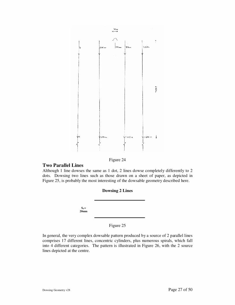
lines. This pattern is illustrated in Figure 24, and indicates the dimensions. These
lines are in the plane of the paper, which can be fixed either horizontally or vertically
– the effect and pattern seems identical. There are no lines perpendicularly out of the
paper.
Although only measured over a distance of 2.1 metres, these 4 lines appear to be parallel within experimental error, have an outward flow, and seem to go to infinity.
Even though the source half sine wave only extended 110mm, the separation distance between the outer lines was 1.35-1.40 metres. As they have different properties to the
4 types of lines generated by, say, banks and ditches, they are being referred to as Type 5 lines. All 4 of these Type 5 lines seem to have the same properties. Unlike
Types 1 – 4 lines, they do not show a colour on a mager disc.
These experiments have been repeated with the following geometric shapes that
produce strong patterns in 3 and 4 dimensional space (presumably the latter indicates
stability in time). A dot, angled cross, vertical cross, circle, Bob’s geometry, vesica
pisces, and a full sine wave. All of these produce a void when dowsing in 5-
dimensional space. This void is in the plane of the paper as well as perpendicular to
the paper. It makes no difference if the paper on which is drawn the geometrical
shape, is fixed either horizontally or vertically.
Further research is obviously required to explain why a 5-dimensional result is only
obtained with a half sine wave, and few other geometries.
Dowsing Geometry v28 Page 27 of 50
Figure 24
Two Parallel Lines Although 1 line dowses the same as 1 dot, 2 lines dowse completely differently to 2
dots. Dowsing two lines such as those drawn on a sheet of paper, as depicted in
Figure 25, is probably the most interesting of the dowsable geometry described here.
Dowsing 2 Lines
Figure 25
In general, the very complex dowsable pattern produced by a source of 2 parallel lines
comprises 17 different lines, concentric cylinders, plus numerous spirals, which fall
into 4 different categories. The pattern is illustrated in Figure 26, with the 2 source
lines depicted at the centre.
S0 =
20mm
Dowsing Geometry v28 Page 28 of 50
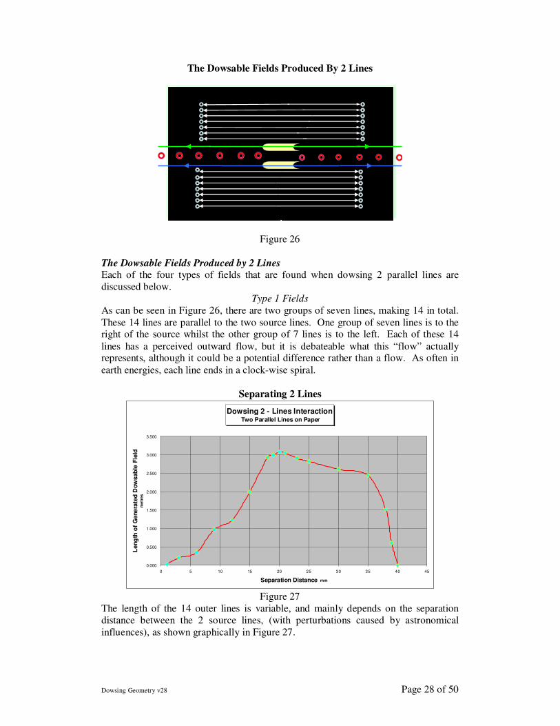
The Dowsable Fields Produced By 2 Lines
9
Figure 26
The Dowsable Fields Produced by 2 Lines Each of the four types of fields that are found when dowsing 2 parallel lines are
discussed below.
Type 1 Fields
As can be seen in Figure 26, there are two groups of seven lines, making 14 in total.
These 14 lines are parallel to the two source lines. One group of seven lines is to the right of the source whilst the other group of 7 lines is to the left. Each of these 14
lines has a perceived outward flow, but it is debateable what this “flow” actually represents, although it could be a potential difference rather than a flow. As often in
earth energies, each line ends in a clock-wise spiral.
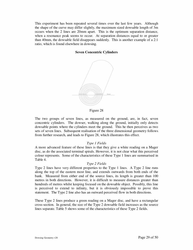
Separating 2 Lines
Figure 27
The length of the 14 outer lines is variable, and mainly depends on the separation
distance between the 2 source lines, (with perturbations caused by astronomical
influences), as shown graphically in Figure 27.
Dowsing 2 - Lines Interaction Two Parallel Lines on Paper
0.000
0.500
1.000
1.500
2.000
2.500
3.000
3.500
0 5 10 15 20 25 30 35 40 45
Separation Distance mm
Leng
th o
f G
ene
rate
d D
ow
sab
le F
ield
m
etr
es
Dowsing Geometry v28 Page 29 of 50
This experiment has been repeated several times over the last few years. Although
the shape of the curve may differ slightly, the maximum sized dowsable length of 3m
occurs when the 2 lines are 20mm apart. This is the optimum separation distance,
when a resonance peak seems to occur. At separation distances equal to or greater
than 40mm, the dowsable field disappears suddenly. This is another example of a 2:1
ratio, which is found elsewhere in dowsing.
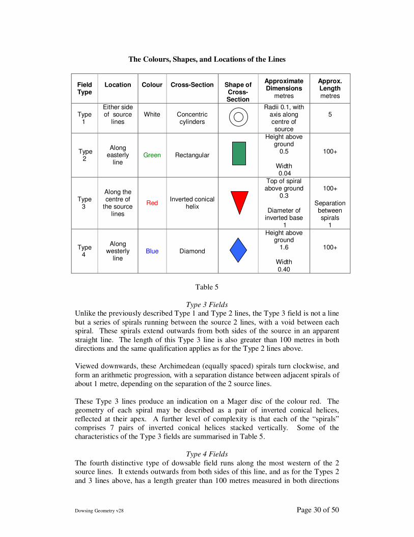
Seven Concentric Cylinders
7 6 5 4 3 2 1 -1 -2 -3 -4 -5 -6 -7 Ground
SEVEN CONCENTRIC CYLINDERS
Figure 11.5
Figure 28
The two groups of seven lines, as measured on the ground, are, in fact, seven
concentric cylinders. The dowser, walking along the ground, initially only detects
dowsable points where the cylinders meet the ground. This he then perceives as two
sets of seven lines. Subsequent realisation of the three dimensional geometry follows
from further research, and leads to Figure 28, which illustrates this effect.
Type 1 Fields
A more advanced feature of these lines is that they give a white reading on a Mager
disc, as do the associated terminal spirals. However, it is not clear what this perceived colour represents. Some of the characteristics of these Type 1 lines are summarised in
Table 4. Type 2 Fields
Type 2 lines have very different properties to the Type 1 lines. A Type 2 line runs along the top of the eastern most line, and extends outwards from both ends of the
bank. Measured from either end of the source lines, its length is greater than 100 metres in both directions. However, it is difficult to measure distances greater than
hundreds of metres whilst keeping focused on the dowsable object. Possibly, this line is perceived to extend to infinity, but it is obviously impossible to prove this
statement. The Type 2 line also has an outward perceived flow in both directions.
These Type 2 lines produce a green reading on a Mager disc, and have a rectangular
cross-section. In general, the size of the Type 2 dowsable field increases as the source
lines separate. Table 5 shows some of the characteristics of these Type 2 fields.
Dowsing Geometry v28 Page 30 of 50
The Colours, Shapes, and Locations of the Lines
Field Type
Location
Colour
Cross-Section
Shape of Cross-Section
Approximate Dimensions
metres
Approx. Length metres
Type
1
Either side of source
lines
White
Concentric cylinders
Radii 0.1, with axis along centre of source
5
Type 2
Along easterly
line Green Rectangular
Height above ground
0.5
Width 0.04
100+
Type 3
Along the centre of
the source lines
Red Inverted conical
helix
Top of spiral above ground
0.3
Diameter of inverted base
1
100+
Separation between spirals
1
Type 4
Along westerly
line Blue Diamond
Height above ground
1.6
Width 0.40
100+
Table 5
Type 3 Fields
Unlike the previously described Type 1 and Type 2 lines, the Type 3 field is not a line
but a series of spirals running between the source 2 lines, with a void between each spiral. These spirals extend outwards from both sides of the source in an apparent
straight line. The length of this Type 3 line is also greater than 100 metres in both directions and the same qualification applies as for the Type 2 lines above.
Viewed downwards, these Archimedean (equally spaced) spirals turn clockwise, and
form an arithmetic progression, with a separation distance between adjacent spirals of
about 1 metre, depending on the separation of the 2 source lines.
These Type 3 lines produce an indication on a Mager disc of the colour red. The
geometry of each spiral may be described as a pair of inverted conical helices,
reflected at their apex. A further level of complexity is that each of the “spirals”
comprises 7 pairs of inverted conical helices stacked vertically. Some of the
characteristics of the Type 3 fields are summarised in Table 5.
Type 4 Fields
The fourth distinctive type of dowsable field runs along the most western of the 2 source lines. It extends outwards from both sides of this line, and as for the Types 2
and 3 lines above, has a length greater than 100 metres measured in both directions
Dowsing Geometry v28 Page 31 of 50
from the ends of the source lines. This Type 4 line has a perceived outward flow, and
gives an indication on a Mager disc of the colour blue. It has a diamond shaped cross-
section. Intriguingly, members of the Dowsing Research Group have reported basic
telepathy when standing on these blue Type 4 fields. Some of the characteristics of
the Type 4 fields can be seen in Table 5.
Orientation
The Type 2 line always runs along the most easterly source line, whilst the Type 4
line always runs along the most westerly of the 2 source lines. When the 2 source lines are orientated exactly magnetic east – west, there is a null point when the Type
2, 3, and 4 lines suddenly disappear. The Type 1 lines do not seem to be affected. The implications of this are discussed in the conclusions.
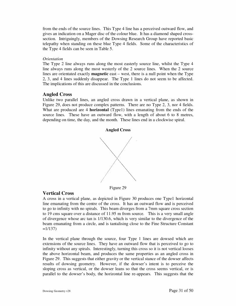
Angled Cross Unlike two parallel lines, an angled cross drawn in a vertical plane, as shown in
Figure 29, does not produce complex patterns. There are no Type 2, 3, nor 4 fields.
What are produced are 4 horizontal (Type1) lines emanating from the ends of the
source lines. These have an outward flow, with a length of about 6 to 8 metres,
depending on time, the day, and the month. These lines end in a clockwise spiral.
Angled Cross
Figure 29
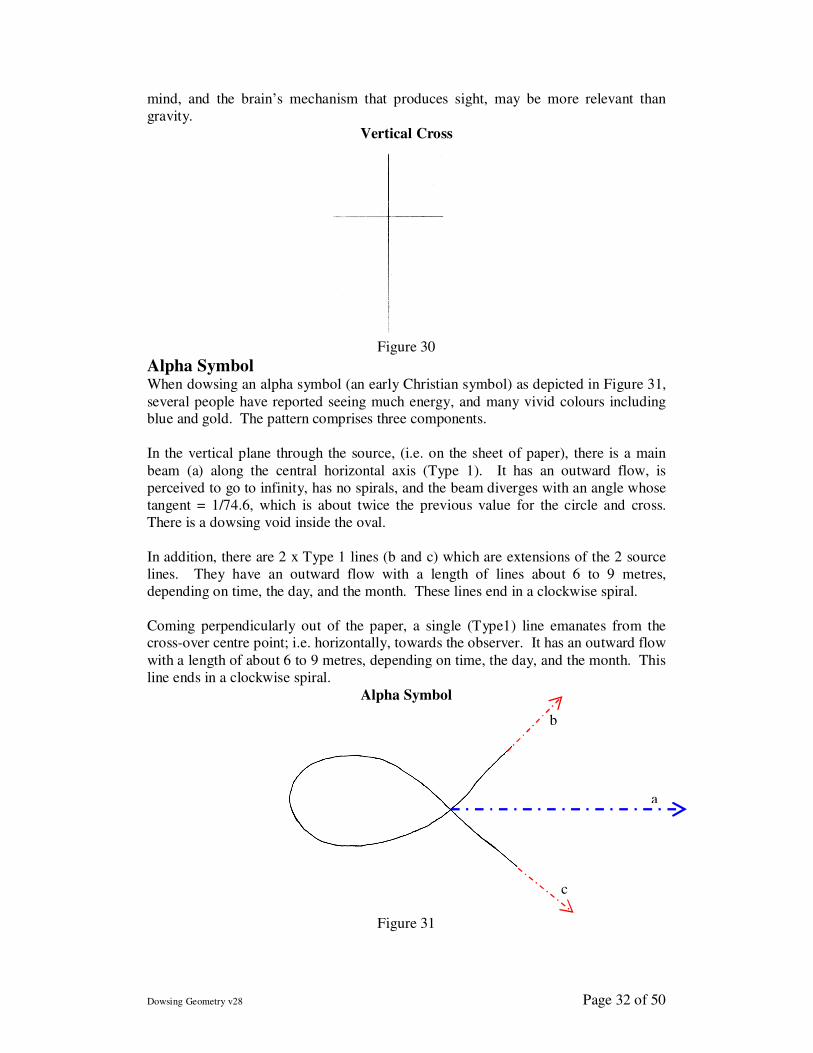
Vertical Cross A cross in a vertical plane, as depicted in Figure 30 produces one Type1 horizontal
line emanating from the centre of the cross. It has an outward flow and is perceived to go to infinity with no spirals. This beam diverges from a 7mm square cross section
to 19 cms square over a distance of 11.95 m from source. This is a very small angle
of divergence whose arc tan is 1/130.6, which is very similar to the divergence of the
beam emanating from a circle, and is tantalising close to the Fine Structure Constant
=1/137)
In the vertical plane through the source, four Type 1 lines are dowsed which are
extensions of the source lines. They have an outward flow that is perceived to go to
infinity without any spirals. Interestingly, turning this cross so it is not vertical looses
the above horizontal beam, and produces the same properties as an angled cross in
Figure 29. This suggests that either gravity or the vertical stance of the dowser affects
results of dowsing geometry. However, if the dowser’s intent is to perceive the sloping cross as vertical, or the dowser leans so that the cross seems vertical, or is
parallel to the dowser’s body, the horizontal line re-appears. This suggests that the
Dowsing Geometry v28 Page 32 of 50
mind, and the brain’s mechanism that produces sight, may be more relevant than
gravity.
Vertical Cross
Figure 30
Alpha Symbol When dowsing an alpha symbol (an early Christian symbol) as depicted in Figure 31,
several people have reported seeing much energy, and many vivid colours including blue and gold. The pattern comprises three components.
In the vertical plane through the source, (i.e. on the sheet of paper), there is a main
beam (a) along the central horizontal axis (Type 1). It has an outward flow, is
perceived to go to infinity, has no spirals, and the beam diverges with an angle whose
tangent = 1/74.6, which is about twice the previous value for the circle and cross.
There is a dowsing void inside the oval.
In addition, there are 2 x Type 1 lines (b and c) which are extensions of the 2 source
lines. They have an outward flow with a length of lines about 6 to 9 metres,
depending on time, the day, and the month. These lines end in a clockwise spiral.
Coming perpendicularly out of the paper, a single (Type1) line emanates from the cross-over centre point; i.e. horizontally, towards the observer. It has an outward flow
with a length of about 6 to 9 metres, depending on time, the day, and the month. This
line ends in a clockwise spiral.
Alpha Symbol
Figure 31
b
a
c
Dowsing Geometry v28 Page 33 of 50
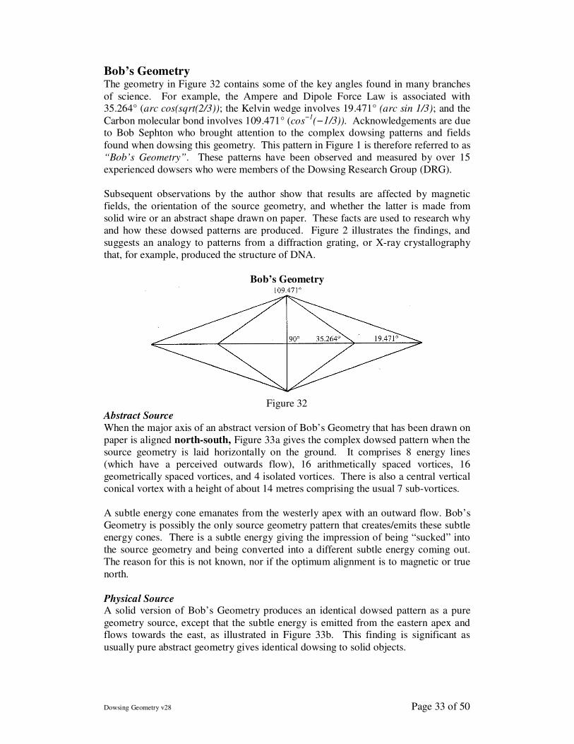
Bob’s Geometry The geometry in Figure 32 contains some of the key angles found in many branches
of science. For example, the Ampere and Dipole Force Law is associated with 35.264° (arc cos(sqrt(2/3)); the Kelvin wedge involves 19.471° (arc sin 1/3); and the
Carbon molecular bond involves 109.471° (cos−1
(−1/3)). Acknowledgements are due to Bob Sephton who brought attention to the complex dowsing patterns and fields
found when dowsing this geometry. This pattern in Figure 1 is therefore referred to as
“Bob’s Geometry”. These patterns have been observed and measured by over 15
experienced dowsers who were members of the Dowsing Research Group (DRG).
Subsequent observations by the author show that results are affected by magnetic
fields, the orientation of the source geometry, and whether the latter is made from
solid wire or an abstract shape drawn on paper. These facts are used to research why
and how these dowsed patterns are produced. Figure 2 illustrates the findings, and
suggests an analogy to patterns from a diffraction grating, or X-ray crystallography
that, for example, produced the structure of DNA.
Bob’s Geometry
Figure 32
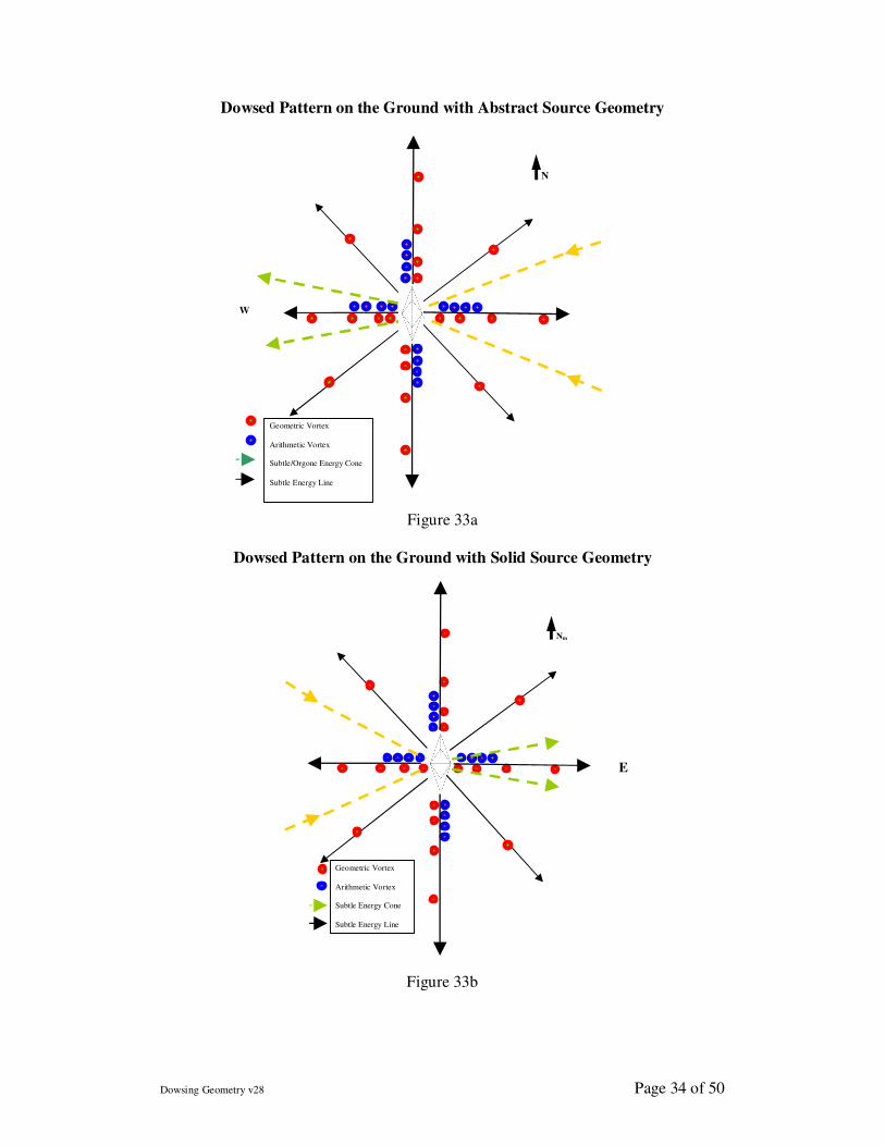
Abstract Source
When the major axis of an abstract version of Bob’s Geometry that has been drawn on
paper is aligned north-south, Figure 33a gives the complex dowsed pattern when the
source geometry is laid horizontally on the ground. It comprises 8 energy lines
(which have a perceived outwards flow), 16 arithmetically spaced vortices, 16
geometrically spaced vortices, and 4 isolated vortices. There is also a central vertical
conical vortex with a height of about 14 metres comprising the usual 7 sub-vortices.
A subtle energy cone emanates from the westerly apex with an outward flow. Bob’s
Geometry is possibly the only source geometry pattern that creates/emits these subtle
energy cones. There is a subtle energy giving the impression of being “sucked” into
the source geometry and being converted into a different subtle energy coming out.
The reason for this is not known, nor if the optimum alignment is to magnetic or true
north.
Physical Source A solid version of Bob’s Geometry produces an identical dowsed pattern as a pure
geometry source, except that the subtle energy is emitted from the eastern apex and flows towards the east, as illustrated in Figure 33b. This finding is significant as
usually pure abstract geometry gives identical dowsing to solid objects.
Dowsing Geometry v28 Page 34 of 50
Dowsed Pattern on the Ground with Abstract Source Geometry
Figure 33a
Dowsed Pattern on the Ground with Solid Source Geometry
Figure 33b
N
W
Nm
Geometric Vortex
Arithmetic Vortex
Subtle Energy Cone
Subtle Energy Line
E
Geometric Vortex
Arithmetic Vortex
Subtle/Orgone Energy Cone
Subtle Energy Line
Dowsing Geometry v28 Page 35 of 50
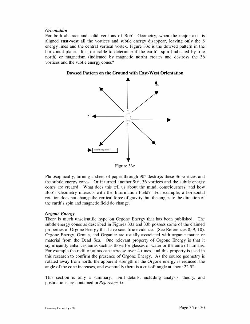
Orientation For both abstract and solid versions of Bob’s Geometry, when the major axis is
aligned east-west all the vortices and subtle energy disappear, leaving only the 8
energy lines and the central vertical vortex. Figure 33c is the dowsed pattern in the
horizontal plane. It is desirable to determine if the earth’s spin (indicated by true
north) or magnetism (indicated by magnetic north) creates and destroys the 36
vortices and the subtle energy cones?
Dowsed Pattern on the Ground with East-West Orientation
Figure 33c
Philosophically, turning a sheet of paper through 90° destroys these 36 vortices and
the subtle energy cones. Or if turned another 90°, 36 vortices and the subtle energy cones are created. What does this tell us about the mind, consciousness, and how
Bob’s Geometry interacts with the Information Field? For example, a horizontal
rotation does not change the vertical force of gravity, but the angles to the direction of
the earth’s spin and magnetic field do change.
Orgone Energy There is much unscientific hype on Orgone Energy that has been published. The
subtle energy cones as described in Figures 33a and 33b possess some of the claimed
properties of Orgone Energy that have scientific evidence. (See References 8, 9, 10).
Orgone Energy, Ormus, and Organite are usually associated with organic matter or
material from the Dead Sea. One relevant property of Orgone Energy is that it
significantly enhances auras such as those for glasses of water or the aura of humans.
For example the radii of auras can increase over 4 times, and this property is used in
this research to confirm the presence of Orgone Energy. As the source geometry is rotated away from north, the apparent strength of the Orgone energy is reduced, the
angle of the cone increases, and eventually there is a cut-off angle at about 22.5°.
This section is only a summary. Full details, including analysis, theory, and postulations are contained in Reference 33.
E
Subtle Energy Lines
N
Dowsing Geometry v28 Page 36 of 50
3 – Dimensions
Banks and Ditches The remarkable findings are that massive 3-dimensional earth-works, known as banks
and ditches, produce exactly the same dowsable pattern as cm. sized 2 parallel lines, which are 2-dimensional. The latter was discussed earlier. This Hyperlink gives
further information on Banks and Ditches.
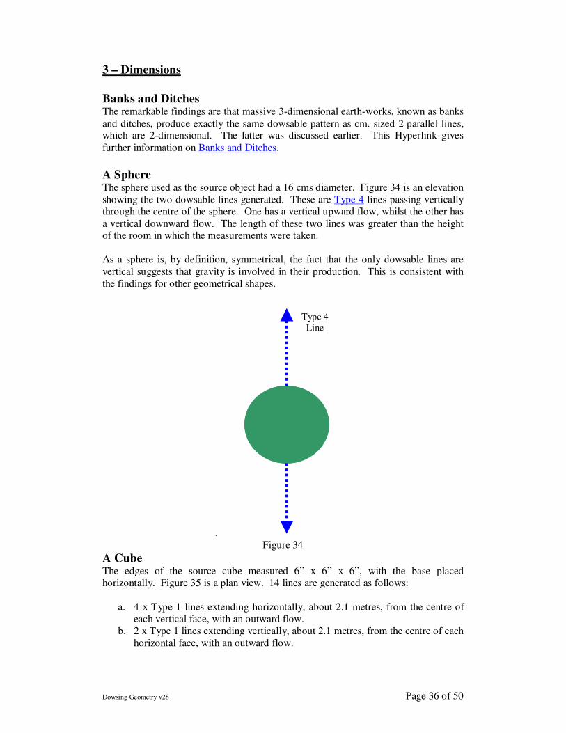
A Sphere The sphere used as the source object had a 16 cms diameter. Figure 34 is an elevation
showing the two dowsable lines generated. These are Type 4 lines passing vertically through the centre of the sphere. One has a vertical upward flow, whilst the other has
a vertical downward flow. The length of these two lines was greater than the height of the room in which the measurements were taken.
As a sphere is, by definition, symmetrical, the fact that the only dowsable lines are
vertical suggests that gravity is involved in their production. This is consistent with
the findings for other geometrical shapes.
.
Figure 34
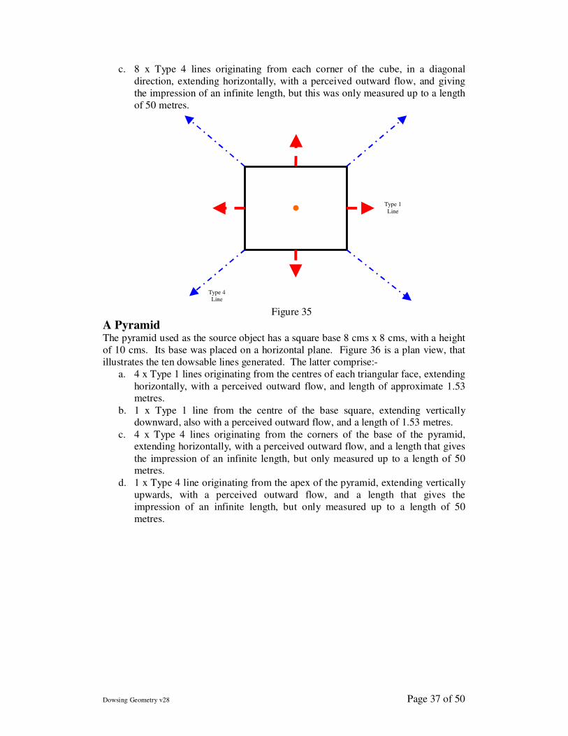
A Cube The edges of the source cube measured 6” x 6” x 6”, with the base placed
horizontally. Figure 35 is a plan view. 14 lines are generated as follows:
a. 4 x Type 1 lines extending horizontally, about 2.1 metres, from the centre of
each vertical face, with an outward flow.
b. 2 x Type 1 lines extending vertically, about 2.1 metres, from the centre of each
horizontal face, with an outward flow.
Type 4
Line
Dowsing Geometry v28 Page 37 of 50
c. 8 x Type 4 lines originating from each corner of the cube, in a diagonal
direction, extending horizontally, with a perceived outward flow, and giving
the impression of an infinite length, but this was only measured up to a length
of 50 metres.
Figure 35
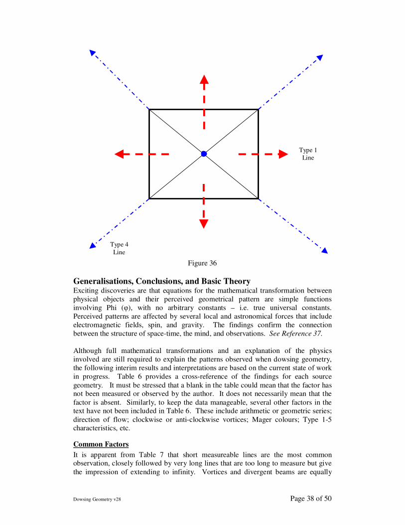
A Pyramid The pyramid used as the source object has a square base 8 cms x 8 cms, with a height
of 10 cms. Its base was placed on a horizontal plane. Figure 36 is a plan view, that
illustrates the ten dowsable lines generated. The latter comprise:-
a. 4 x Type 1 lines originating from the centres of each triangular face, extending
horizontally, with a perceived outward flow, and length of approximate 1.53 metres.
b. 1 x Type 1 line from the centre of the base square, extending vertically downward, also with a perceived outward flow, and a length of 1.53 metres.
c. 4 x Type 4 lines originating from the corners of the base of the pyramid, extending horizontally, with a perceived outward flow, and a length that gives
the impression of an infinite length, but only measured up to a length of 50 metres.
d. 1 x Type 4 line originating from the apex of the pyramid, extending vertically
upwards, with a perceived outward flow, and a length that gives the
impression of an infinite length, but only measured up to a length of 50
metres.
Type 1
Line
Type 4
Line
Dowsing Geometry v28 Page 38 of 50
Figure 36
Generalisations, Conclusions, and Basic Theory Exciting discoveries are that equations for the mathematical transformation between
physical objects and their perceived geometrical pattern are simple functions
involving Phi (φ), with no arbitrary constants – i.e. true universal constants.
Perceived patterns are affected by several local and astronomical forces that include
electromagnetic fields, spin, and gravity. The findings confirm the connection
between the structure of space-time, the mind, and observations. See Reference 37.
Although full mathematical transformations and an explanation of the physics
involved are still required to explain the patterns observed when dowsing geometry,
the following interim results and interpretations are based on the current state of work
in progress. Table 6 provides a cross-reference of the findings for each source
geometry. It must be stressed that a blank in the table could mean that the factor has not been measured or observed by the author. It does not necessarily mean that the
factor is absent. Similarly, to keep the data manageable, several other factors in the text have not been included in Table 6. These include arithmetic or geometric series;
direction of flow; clockwise or anti-clockwise vortices; Mager colours; Type 1-5 characteristics, etc.
Common Factors
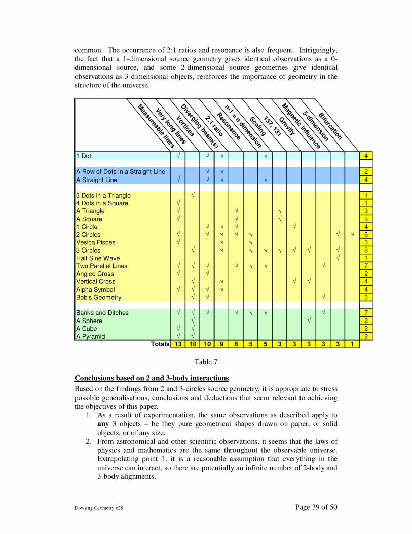
It is apparent from Table 7 that short measureable lines are the most common observation, closely followed by very long lines that are too long to measure but give
the impression of extending to infinity. Vortices and divergent beams are equally
Type 1
Line
Type 4
Line
Dowsing Geometry v28 Page 39 of 50
common. The occurrence of 2:1 ratios and resonance is also frequent. Intriguingly,
the fact that a 1-dimensional source geometry gives identical observations as a 0-
dimensional source, and some 2-dimensional source geometries give identical
observations as 3-dimensional objects, reinforces the importance of geometry in the
structure of the universe.
Measureable lines
Very long
linesVortices
Divergin
g beam(s)
2:1 ratioR
esonance
n-1 = n dimensio
nScaling
137, 131G
ravity
Mag
netic influence
5-dimension
Bifurcation
1 Dot √ √ √ √ 4
A Row of Dots in a Straight Line √ √ 2
A Straight Line √ √ √ √ 4
3 Dots in a Triangle √ 1
4 Dots in a Square √ 1
A Triangle √ √ √ 3
A Square √ √ √ 3
1 Circle √ √ √ √ 4
2 Circles √ √ √ √ √ √ √ 6
Vesica Pisces √ √ √ 3
3 Circles √ √ √ √ √ √ √ √ 8
Half Sine Wave √ 1
Two Parallel Lines √ √ √ √ √ √ √ 7
Angled Cross √ √ 2
Vertical Cross √ √ √ √ 4
Alpha Symbol √ √ √ √ 4
Bob’s Geometry √ √ √ 3
Banks and Ditches √ √ √ √ √ √ √ 7
A Sphere √ √ 2
A Cube √ √ 2
A Pyramid √ √ 2
Totals 13 10 10 9 6 5 5 3 3 3 3 3 1
Table 7
Conclusions based on 2 and 3-body interactions
Based on the findings from 2 and 3-circles source geometry, it is appropriate to stress
possible generalisations, conclusions and deductions that seem relevant to achieving
the objectives of this paper.
1. As a result of experimentation, the same observations as described apply to
any 3 objects – be they pure geometrical shapes drawn on paper, or solid
objects, or of any size.
2. From astronomical and other scientific observations, it seems that the laws of
physics and mathematics are the same throughout the observable universe. Extrapolating point 1, it is a reasonable assumption that everything in the
universe can interact, so there are potentially an infinite number of 2-body and 3-body alignments.
Dowsing Geometry v28 Page 40 of 50
3. In theory, the 2 or 3 objects being studied can be paired or aligned and interact
with all other objects in the universe, and therefore significant affect
experimental results.
4. To avoid the paradox in points 2 and 3, the dowser’s conscious intent as to
which 2 or 3 objects are being studied is fundamental to the patterns in this
database.
5. This tuning out of the rest of the universe by the observer’s mind, prevents an overload of information.
6. As a demonstration of points 4 and 5, if the dowser’s intent is only on circles B and C in Figure 21, the conventional 2-body interaction is obtained, as
detailed earlier in Figure 12 and Table 4. In other words, the simple act of changing intent dramatically alters the observations from the middle to the end
column in Table 4. 7. If, as in point 6, consciousness and intent can change observed geometrical
patterns, how far can this be generalised to explain, for example, quantum
mechanics where it has long been known that observations affect results?
8. The evidence supports the postulate that the mind’s conscious intent creates a
node with each object being studied. So if 3 objects are being considered, 3
nodes are created, with a 4th being the dowser’s mind: information being
transferred by waves, the nature of which is one of the objectives of this paper.
9. This postulate can be generalised to explain why the observations in scientific
experiments can influence the results.
10. This leads to the interesting questions of how any 2 or 3 bodies are aware of
each others presence, and how they should interact. Are the nodal points only
created by conscious intent, or can they exist without observation?
11. Similarly, how do 3 inert circles (or solid objects) know they are aligned?
12. The circles are giving the appearance of a form of consciousness, but more probably they are just reflecting the structure of the universe.
13. In a possible answer to points 10, 11, and 12, it would seem from Figures 18, 19 and 21 that alignment of the 3 bodies produces a 5-dimensional effect.
14. Does this Type 5 mechanism allow 3 bodies to be “aware” that they are in alignment? This must be part of the structure of the universe. i.e. perceived
consciousness 15. Does this effect support the hypothesis that the universe is a 5-dimensional
hologram?
Magnetism
From the experimental results regarding the importance of magnetic east-west
orientation of the geometry comprising 2 parallel lines, it would seem that magnetism is a factor in producing Type 2, 3, and 4 lines. There are no observations indicating
that Type 1 lines are affected by magnetism.
These conclusions have been confirmed by repeating the experiments with two
parallel source lines after placing them in a Faraday cage to screen out any magnetic
effects. For all orientations, the Type 2, 3, and 4 lines are not present
a) When both the dowser and the source geometry are in the cage, and
b) When only the source geometry is in the cage.
This suggests that magnetism is relevant between the two source lines, and not
necessarily between the dowser and the source geometry. Therefore, this discovery
Dowsing Geometry v28 Page 41 of 50
supports the theory that the waves causing resonance are emanating from each source
line on the paper, as opposed to the image of the 2 lines in the information field, or the
brain’s model of what is being perceived.
This leads to an unfortunate anomaly, as it has been known for several years that
Types 2, 3, and 4 fields are unaffected by screening. For example, it is possible from
within a Faraday cage, to detect Type 2 fields from a plant, or transmit mind generated geometric shapes via Type 4 fields to a remote location. However, these
irrelevances to screening only apply to single objects, not two objects interacting.
Waves and Phase
The null result from dowsing the geometry that resembles a half sine wave may be a further clue to wave involvement in dowsing geometry. A wave that is a reflection of
the half sine wave shape, i.e. the same shape, but 180° out of phase, would produce a null/void interference dowsable pattern. This suggests that the wavelength involved
when dowsing this shape may equal the conceptual wave length and amplitude of the source geometry being dowsed. If so, the intent of a dowser generates an associated
wave, whose shape, wavelength, phase, and amplitude are determined by the geometry being dowsed.
The above examples relate to dowsing single source objects. The following situations
relate to 2 interacting objects.
Interactions, Resonance and Waves
That a resonance peak is obtained is good evidence that dowsing two source objects A &
B, such as 2 circles or 2 lines, involves vibrations. In other words, conceptually, when the
vibrations perceived to be emitted by each of the two source objects are in phase,
resonance occurs. Figure 37 is a general pictorial representation of this standard effect for
two objects A and B. When the peaks of the waves emanating from A and B are both
superimposed, a larger peak is produced, as in Figure 37a. A half wavelength is used in
this simple example, but the same principle applies to other wave forms. Figure 37b
illustrates the two waves out of phase, producing a null effect.
Let us make two reasonable postulates:
the 2 objects A & B being dowsed are 2 nodal points, and
each object is associated with, or is emitting, the same vibrational frequency.
According to standard wave theory, frequency is a function of wavelength (λ). As
resonance occurs when the wavelengths are superimposed (ie in phase), the optimum separation distance, S0, between the two lines is a fraction or an integer (i) of a particular
wavelength (λ).
i.e. S0 = i .λ. (i)
So what is the value of this wavelength? To answer this question, it is instructive to
discuss what happens when the two lines are more than 40 mm apart, or the 2 circles
are more than 60mm apart. The observations (as in Figures 13 and 27) are that no
dowsable fields exist, leading to two possible reasons.
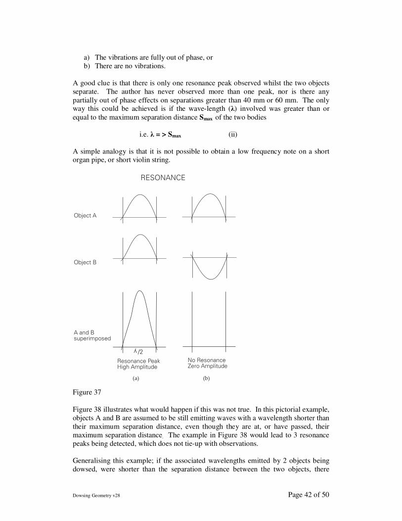
Dowsing Geometry v28 Page 42 of 50
a) The vibrations are fully out of phase, or
b) There are no vibrations.
A good clue is that there is only one resonance peak observed whilst the two objects
separate. The author has never observed more than one peak, nor is there any
partially out of phase effects on separations greater than 40 mm or 60 mm. The only way this could be achieved is if the wave-length (λ) involved was greater than or
equal to the maximum separation distance Smax of the two bodies
i.e. λ = > Smax (ii)
A simple analogy is that it is not possible to obtain a low frequency note on a short organ pipe, or short violin string.
Object A
Object B
A and Bsuperimposed
Resonance PeakHigh Amplitude
No ResonanceZero Amplitude
RESONANCE
(a) (b)
y
/2
Figure 37
Figure 38 illustrates what would happen if this was not true. In this pictorial example,
objects A and B are assumed to be still emitting waves with a wavelength shorter than
their maximum separation distance, even though they are at, or have passed, their
maximum separation distance. The example in Figure 38 would lead to 3 resonance
peaks being detected, which does not tie-up with observations.
Generalising this example; if the associated wavelengths emitted by 2 objects being
dowsed, were shorter than the separation distance between the two objects, there
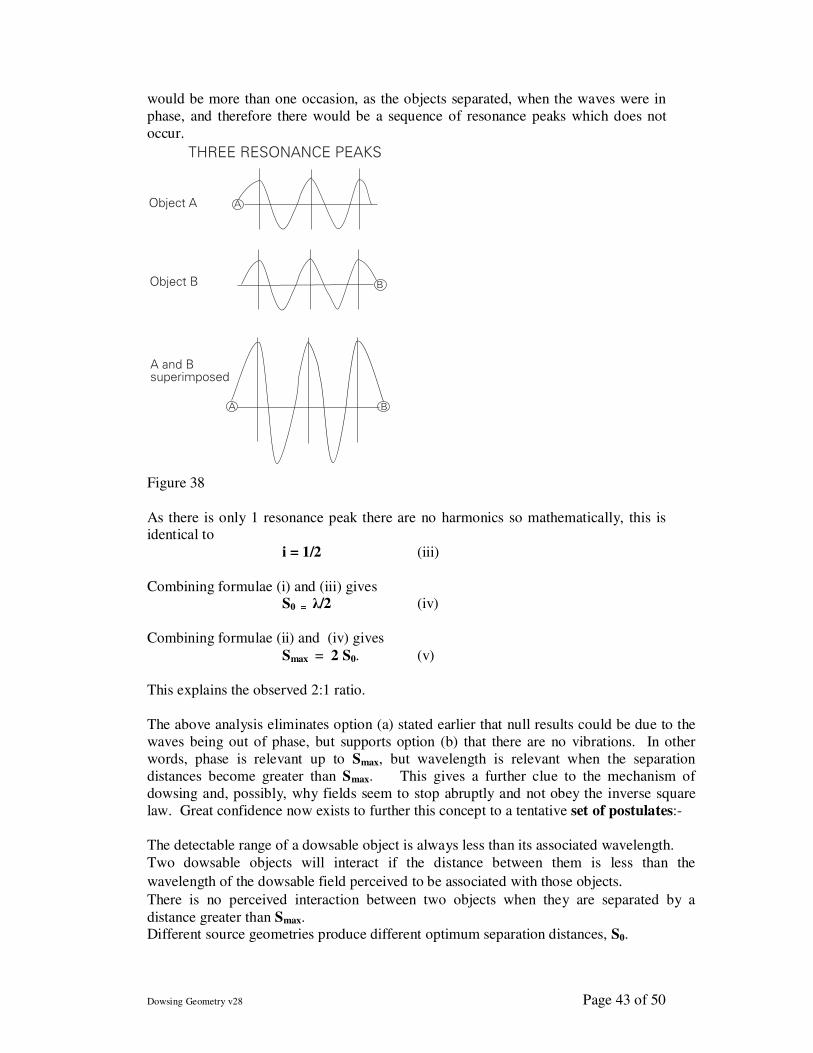
Dowsing Geometry v28 Page 43 of 50
would be more than one occasion, as the objects separated, when the waves were in
phase, and therefore there would be a sequence of resonance peaks which does not
occur.
Object A
Object B
A and Bsuperimposed
THREE RESONANCE PEAKS
A
B
A B
Figure 38
As there is only 1 resonance peak there are no harmonics so mathematically, this is identical to
i = 1/2 (iii)
Combining formulae (i) and (iii) gives S0 = λ/2 (iv)
Combining formulae (ii) and (iv) gives
Smax = 2 S0. (v)
This explains the observed 2:1 ratio.
The above analysis eliminates option (a) stated earlier that null results could be due to the
waves being out of phase, but supports option (b) that there are no vibrations. In other
words, phase is relevant up to Smax, but wavelength is relevant when the separation
distances become greater than Smax. This gives a further clue to the mechanism of
dowsing and, possibly, why fields seem to stop abruptly and not obey the inverse square
law. Great confidence now exists to further this concept to a tentative set of postulates:-
The detectable range of a dowsable object is always less than its associated wavelength.
Two dowsable objects will interact if the distance between them is less than the
wavelength of the dowsable field perceived to be associated with those objects.
There is no perceived interaction between two objects when they are separated by a
distance greater than Smax. Different source geometries produce different optimum separation distances, S0.
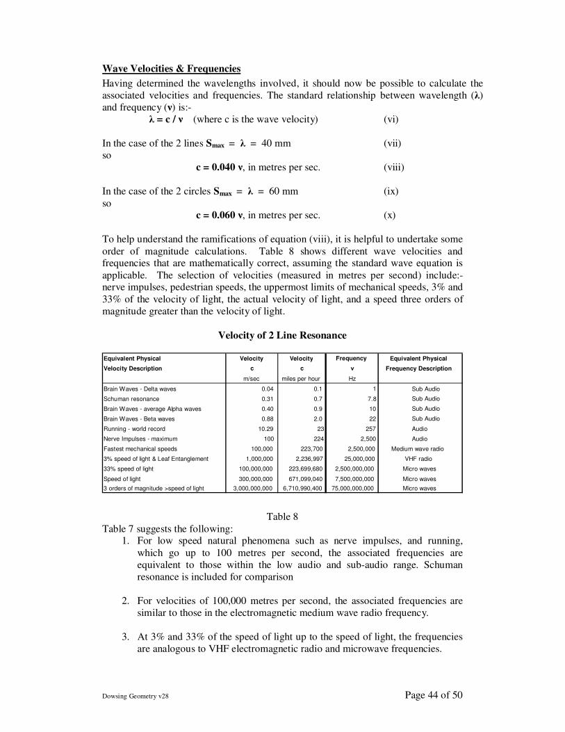
Dowsing Geometry v28 Page 44 of 50
Wave Velocities & Frequencies
Having determined the wavelengths involved, it should now be possible to calculate the
associated velocities and frequencies. The standard relationship between wavelength (λ) and frequency (ν) is:-
λ = c / ν (where c is the wave velocity) (vi)
In the case of the 2 lines Smax = λ = 40 mm (vii)
so
c = 0.040 ν, in metres per sec. (viii)
In the case of the 2 circles Smax = λ = 60 mm (ix)
so
c = 0.060 ν, in metres per sec. (x)
To help understand the ramifications of equation (viii), it is helpful to undertake some
order of magnitude calculations. Table 8 shows different wave velocities and frequencies that are mathematically correct, assuming the standard wave equation is
applicable. The selection of velocities (measured in metres per second) include:- nerve impulses, pedestrian speeds, the uppermost limits of mechanical speeds, 3% and
33% of the velocity of light, the actual velocity of light, and a speed three orders of
magnitude greater than the velocity of light.
Velocity of 2 Line Resonance
Table 8
Table 7 suggests the following: 1. For low speed natural phenomena such as nerve impulses, and running,
which go up to 100 metres per second, the associated frequencies are
equivalent to those within the low audio and sub-audio range. Schuman
resonance is included for comparison
2. For velocities of 100,000 metres per second, the associated frequencies are
similar to those in the electromagnetic medium wave radio frequency.
3. At 3% and 33% of the speed of light up to the speed of light, the frequencies
are analogous to VHF electromagnetic radio and microwave frequencies.
Equivalent Physical Velocity Velocity Frequency Equivalent Physical Velocity Description c c ν Frequency Description
m/sec miles per hour Hz Brain Waves - Delta waves 0.04 0.1 1 Sub Audio Schuman resonance 0.31 0.7 7.8 Sub Audio
Brain Waves - average Alpha waves 0.40 0.9 10 Sub Audio Brain Waves - Beta waves 0.88 2.0 22 Sub Audio Running - world record 10.29 23 257 Audio
Nerve Impulses - maximum 100 224 2,500 Audio Fastest mechanical speeds 100,000 223,700 2,500,000 Medium wave radio
3% speed of light & Leaf Entanglement 1,000,000 2,236,997 25,000,000 VHF radio
33% speed of light 100,000,000 223,699,680 2,500,000,000 Micro waves Speed of light 300,000,000 671,099,040 7,500,000,000 Micro waves 3 orders of magnitude >speed of light 3,000,000,000 6,710,990,400 75,000,000,000 Micro waves
Dowsing Geometry v28 Page 45 of 50
4. At 3 orders of magnitude greater than the speed of light, the frequencies are
similar to upper micro wave frequencies.
Which of these orders of magnitude relates to on-site observations and measurements?
Although possibly not relevant to dowsing pure geometry, for earth energies, which are
normally associated with matter, it is generally accepted that velocities are at the bottom of
the range. For example, at Avebury, smaller stones (such as stone 41) have been observed (e.g. by Wessex Dowsers on 4th June 2001 at 11 am) to pulse at a rate of between 60 – 24
times per minute. i.e. 1 – 0.4 times per second.
Similarly, before reaching erroneous conclusions about velocities and frequencies, researchers should be aware that:-
1. Brainwave activity ranges from about 22 Hz for beta waves, via 8-12 Hz for alpha waves, 4-7 Hz for theta waves, and down to 1-3 Hz for delta waves in deep sleep.
2. 7.8 Hz is the Schumann resonance frequency of the Earth’s geomagnetic field, and
ionosphere, and is the number of times light travels round the Earth in one second.
3. 50 m/sec is an average speed of nerve impulses, but can travel at a rate of between 5 -
100 metres per second.
It is therefore important that dowsers do not interfere with their own experiments, and
finish up just measuring their own nervous systems! This concept also has a similarity to
the “Uncertainty Principle” which is a facet of quantum physics.
The Way Forward The following are suggested experiments and theoretical challenges that other
researchers may wish to develop.
1 Independent research is required to duplicate and substantiate the findings in this paper.
2 What are the mathematical transformations that give rise to the observed
patterns?
3 In particular, why is a cylindrical dowsable field perceived for a two line source? How does the resonance between these 2 lines create and affect the
dimensions of the observed cylinder? Why does the length of this cylinder
vary from 0 – 3m
a) as the lines are separated?
b) over the course of a lunar month?
What is the sequence between the mind, the 2 lines, and the Information Field to
produce the observed complex pattern?
4 If a half sine wave source produces a null effect because the interfering wave
emanating from the dowser mimics the geometry of the source, but is 180° out
of phase, how could this conceptual mechanism work as the phase or
wavelength would be affected by the varying distance between the 2 nodal points created by the dowser and the source?
Dowsing Geometry v28 Page 46 of 50
5 A half sine wave produces a null effect, which is the opposite to a full sine
wave which produces a plethora of dowsable patterns: This raises the
following queries.
a) Why is the dowsing associated with a half sine wave out of phase, but a
full sine wave is not?
b) Why do no other geometric shapes investigated above give a null effect?
6 Does the theoretical explanation for 2-body interaction patterns (e.g. 2 circles)
also explain the totally different patterns for single object geometry (e.g. dowsing one circle)?
7 When a dowser is observing a single object, such as a circle, is this interaction
(i.e. between dowser and source object) the same as the explanation given earlier for 2 circles interacting?
8 When a dowser believes he is observing a 2-body interaction (e.g. 2 circles), is
this really a 3-body interaction in which the 2 circles are each emitting waves
plus waves emitted by the dowser? A similar question applies to observing a
single object. In other words, is this an example of the uncertainty principle,
with the dowser affecting results, or is the dowser actually creating the effect
by becoming a nodal point?
9 Are the dowser and the objects being dowsed actively “emitting waves /
vibrations” or are they just passive nodes?
10 Why are 20mm and 40mm, respectively, the optimum and maximum
separation distances for 2 lines? These results seem unusual; dowsing
measurements change depending on the time of the day, the day of the lunar month, the month in the year, etc. Are these values universal or personal?
11 The above optimum separation distances, S0, are for lines and circles. Do
other interacting shapes such as two triangles have different values for S0?
12 It should be investigated if the divergence angles of some beams are arctan1/137, or if the similar figure obtained was a coincidence.
13 It has been shown that magnetism is a factor in producing certain dowsable
lines. Is this just the earth’s magnetic field, or can any magnetism produce the
same effect? Can magnetism affect other dowsable results?
14 Apart from 2 parallel lines, what other source geometry produces Type 2, 3,
and 4 lines that are affected by magnetism?
15 It was shown earlier that for Type 2, 3, and 4 fields and magnetism, the
interaction between two lines occurred on the source paper. Does this apply
only where magnetism is involved, or does it apply in general? Conceptually,
are the associated waves perceived to be emanating from each object occur:
a) On the source paper b) In the information field
c) Within the model in the dowser’s brain of the perceived dowsing?
Dowsing Geometry v28 Page 47 of 50
16 What is the nature of these waves? Are they
a) Transverse, like water waves, where the variations in the amplitude is
90° to the direction of the wave. (e.g. a “stationary” cork bobbing
vertically up and down in water waves).
b) Longitudinal, like waves in an organ pipe, where the variations in
amplitude are in the direction of the wave. c) Torsional, where the waves twist in a circular motion at right angles to
the direction of the wave?
On information dowsing, the indication is obtained that longitudinal waves are the interaction mechanism, with a standing wave created between the 2 source
objects that act as nodes. This is supported as the maximum amplitude of the longitudinal waves as measured by dowsing is, as expected, at the centre of 2
equal sized source objects. This requires to be confirmed with different
experiments.
17 Table 5 contains a range of velocities and frequencies that
a) Apply if the resonance model adopted for 2-body interaction is correct.
b) Are mathematically logical if standard wave theory applies.
It is necessary to determine experimentally if either or both of the statements
are true.
Please contact the author at [email protected] with any mathematical
transformation that provides an explanation for these Dowsing Geometry
observations. Alternatively, any relevant experimental results, comments, or
suggestions will be appreciated.
Acknowledgements Acknowledgements are due to the UK Dowsing Research Group (DRG) members who assisted in this avenue of research, helped to confirm many of the findings, and
following their enthusiastic review of the author’s lectures, encouraged its
documentation. In particular, recognition is due to Jim Lyons for his suggestions, and
identifying some of the mathematical ratios, and to Bob Sephton who initially
discovered some of the basic patterns and their properties.
Dowsing Geometry v28 Page 48 of 50
References and Relevant Author’s Original Research Papers
1. The British Society of Dowsers, Earth Energies Group : An Encyclopaedia of Terms
2. The British Society of Dowsers website http://www.britishdowsers.org/
3. James Spottiswoode, Journal of Scientific Exploration : June 1997, Vol. 11, No. 2, Cognitive Sciences Laboratory, Palo Alto
4. Measuring Range, September 2001, Vol. 39 No. 273 The Journal of the British Society of Dowsers
5. The Journal of the British Society of Dowsers : Measuring Dowsing, Volume 39 No. 273, September 2001
6. The Physics of Dowsing & the Brain, December 2001, Vol. 6 No 24 The BSD Earth Energy Group Newsletter
7. Two Body Interaction Part 1, December 2002, Vol. 39 No 278 Dowsing Today
8. Two Body Interaction Part 2, March 2003, Vol.40 No 279 Dowsing Today
9. Dowsing Today : Auras Revisited - Parts 1, 2, 3, December 2003 – March 2005, Vol.
40 Nos. 282, 285, 287
10. Keen, Jeffrey : Consciousness, Intent, and the Structure of the Universe,
Trafford, 2005, 1-4120-4512-6, http://www.trafford.com/robots/04-2320.html 11. The American Dowser : The Anatomy of Conical Helices, Consciousness, and
Universal Constants – Parts 1- 4, February - October 2007, Vol. 47 Nos. 1, 2, 3, 4 12. Physics World : Dark Energy, December 2007, Vol. 20 No. 12
13. Dowsing Today : The Journal of the British Society of Dowsers : Angkor Wat,
Consciousness, and Universal Constants – Parts 1- 2, September - December 2007,
Vol. 41 Nos. 297, 298
14. ASD Digest : The Tree of Life and Universal Constants, Winter 2008-09, Vol.49 Issue
No. 1
15. Further details can be found on the author’s website www.jeffreykeen.org
16. Physics World : The Digital Universe, Seth Lloyd, November 2008, Vol. 21 No. 11
17. Dowsing Today : Measuring the Size of a Dowsable Field, September 2008, Vol. 41,
No. 301
18. Network Review : From Banks and Ditches to Dowsing Two-Dimensional Geometry,
Spring 2009, No. 99
19. Model of Consciousness, April 2009, Vol. 65 No 4 World Futures – The Journal of
General Evolution
20. The Causes of Variations When Making Dowsable Measurements; Part 1 -
Introduction and Personal Factors, 28 November 2009, e-paper online at http://vixra.org/abs/0911.0062
21. The Causes of Variations When Making Dowsable Measurements; Part 2 Daily
Variations Caused by the Earth Spinning on Its Axis, 10 December 2009, e-paper
online at http://vixra.org/abs/0912.0024 22. The Causes of Variations When Making Dowsable Measurements; Part 3- Monthly
and Annual Variations caused by Gravity, 24 December 2009, e-paper online at
http://vixra.org/abs/0912.0049
23. The Causes of Variations When Making Dowsable Measurements; Part- 4 The Effects
of Geometric Alignments and Subtle Energies, 7 January 2010, e-paper online at
http://vixra.org/abs/1001.0004
24. The Causes of Variations When Making Dowsable Measurements; Part 5-
Communicating Information Instantaneously across the Solar System, 7 January 2010,
e-paper online at http://vixra.org/abs/1001.0012
25. Auras Revisited - Parts 1, 2, and 3, December 2003, Vol. 40 No 282 Dowsing Today
Dowsing Geometry v28 Page 49 of 50
26. Is Dowsing a Useful Tool for Serious Scientific Research? October 2010,
Vol. 66 No 8, World Futures: Taylor & Francis - The Journal of General Evolution
27. A Standard “Yardstick” and Protocol for Dowsing Research Measurements; October
2009, e-paper online at http://vixra.org/abs/0910.0037 28. Using Noetics to Determine the Geometric Limits of 3-Body Alignments that Produce
Subtle Energies, 10 January 2010, e-paper online at http://vixra.org/abs/1005.0018
29. From Banks and Ditches to Dowsing 2-dimensional Geometry, Network Review, Spring 2009, No 99
30. The Effects of Gravity on the Mind's Perception, 12 November 2010,
Published as an e-print in http://vixra.org/abs/1011.0026
31. The Auras of Circles and Abstract Geometry, their Interaction with Space-time, and
their Effects on the Mind’s Perception, 28 February 2011, e-paper online at
http://vixra.org/abs/1102.0055
32. 2-Body Interaction with Space-Time and the Effects on the Mind's Perception, 6 Mar
2011, Published as an e-print in viXra:1103.0017
33. The Positive Feedback of Tetrahedral Geometry with Space-Time and Its Effects on the
Mind's Perception, 10 Mar 2011, Published as an e-print in viXra:1103.0029
34. Variation in Dowsing Measurements due to the Combined Vorticity in the Ecliptic
Plane of the Earth’s Orbit around the Sun, and the Spin of the Earth around its Tilted
Axis, 25 May 2011, Published as an e-print in http://vixra.org/abs/1105.0039 35. Consciousness, Vorticity, and Dipoles, July 2006, Vol. 62 No 5 World Futures – The
Journal of General Evolution 36. How Dowsing Works, 10 June 2011 Published as an e-print in
http://vixra.org/abs/1106.0015
37. The Mind, Intergalactic Space, and Phi (φ), 23 June 2011, Published as an e-print
in http://vixra.org/abs/1106.0051
Bibliography and Further Reading 38. Bird, Christopher : The Divining Hand, Shiffer Publishing, 1993.
39. Bekenstein, Jacob : Information in the Holographic Universe, Scientific
American, 2003
40. Bohm, David : The Undivided Universe, Routledge, 2005, 041512185X
41. Bohm, David : Wholeness and the Implicate Order, Routledge,1980
42. Currivan, Jude : The Wave, O-Books; 2005, 1-905047-33-9
43. Dyer, Dr Wayne : The Power of Intention, Hay House 2004
44. Edwards, Lawrence : The Vortex of Life, Floris, 1993, 0-86315-148-5
45. Greene, Brian : The Fabric of the Cosmos, Allen Lane, 2004
46. Hansard, Christopher : The Tibetan Art of Positive Thinking, Hodder, 2003
47. Hawking, Stephen : The Universe in a Nutshell, Bantam Press, 2001
48. Laszlo, Ervin : The Connectivity Hypothesis, SUNY Press, 2003
49. Laszlo, Ervin : Science and the Akashic Field, Inner Traditions; 2004; 50. Lloyd, Seth: The Digital Universe, Physics World, November 2008, Vol. 21 No. 11
51. Lyons, James : Quantifying Effects In Consciousness, University of Hull 1998 52. McTaggart, Lynne : The Field, Harper Collins, 2001
53. Merrick, Richard : Interference (A Grand Scientific Musical Theory), 2009,
Dowsing Geometry v28 Page 50 of 50
54. Mitchell, Edgar : Nature’s Mind: the Quantum Hologram,
http:www.edmitchellapollo14.com
55. Muller, Hartmut: Global Scaling, http://globalscalingtheory.com/ .
56. Penrose, Roger : Shadows of the Mind, Oxford University Press, 1994
57. Penrose, Roger : The Emperor’s New Mind, Oxford University Press, 1999
58. Pribram, Karl : Consciousness Reassessed, Mind and Matter, 2004
59. Radin, Dean : Conscious Universe, Harper, 1997, 0062515025
60. Radin, Dean : Entangled Minds, Paraview, 2006, 1-4165-1677-8.
61. Rosenblum, Bruce & Kuttner, Fred : Quantum Enigma, OUP/Duckworth, 2007
Sheldrake, Rupert : Morphic Resonances, Inner Traditions, 2000
62. Sheldrake, Rupert : The Sense of being Stared At, Arrow, 2004 63. Spottiswoode, James : Journal of Scientific Exploration : June 1997, Vol. 11, No. 2,
Cognitive Sciences Laboratory, Palo Alto 64. Smolin, Lee : The Trouble with Physics, Allen Lane, 2006, 978-0-713-99799-6
65. Stewart, Malcolm : Patterns of Eternity, Floris Books, 2009
66. Talbot, Michael : The Holographic Universe, Harper, 1996, 0586091718
67. Tiller, William : Subtle Energies, Intentionality and Consciousness, Pavior 1997,
68. Tiller, William : Conscious Acts of Creation, Pavoir, 2001, 019293310531
69. Vederal, Vlatko : Decoding Reality, Oxford University Press, March 2010
70. Verlinde, Erik P: On the Origin of Gravity and the Laws of Newton, 6 Jan 2010,
http://arxiv.org/abs/1001.0785.
71. Wallace, Alan : Hidden Dimensions (The Unification of Physics and Consciousness),
Columbia University Press, 2007.
© 2011 by Jeffrey S Keen
All rights reserved. No part of this article may be reproduced, stored in a retrieval system, or transmitted or translated in machine language in any form or by any means,
electronic, mechanical, photocopying, recording, or otherwise, without the prior written permission of the author. The moral right of Jeffrey S Keen to be identified as
author of this work has been asserted in accordance with the copyright, design, and patents act 1988.