Embed Size (px)
Citation preview
DSM MotionImmediate Commands
Objectives
UPON COMPLETION OF THIS MODULE, YOU SHOULD BE ABLE TO: • Describe the Command and Feedback interface to DSM;
• Command servo axis motion with no PLC logic;
• Modify numerous servo axis configuration parameters dynamically and without PLC logic.

DSM Motion Immediate Commands
1 - 2 GE Fanuc Automation Americas Training Services GFS-384
DSM Motion Immediate Commands
Overview This lab is designed to illustrate the ability of the DSM Motion Controller module to control servo axes with little or no PLC logic programming. In order to illustrate this, no PLC logic program is used for this lab. Instead, this lab makes use of the control functionality automatically mapped into output bits (PLC %Q references) and output words (PLC %AQ references) by the configuration of the DSM module. The lab then uses an operator interface to actually set bits and write values into the PLC to initiate motion or change motion parameters such as move distance or velocity. These inputs and outputs to the DSM module are refreshed each PLC scan.
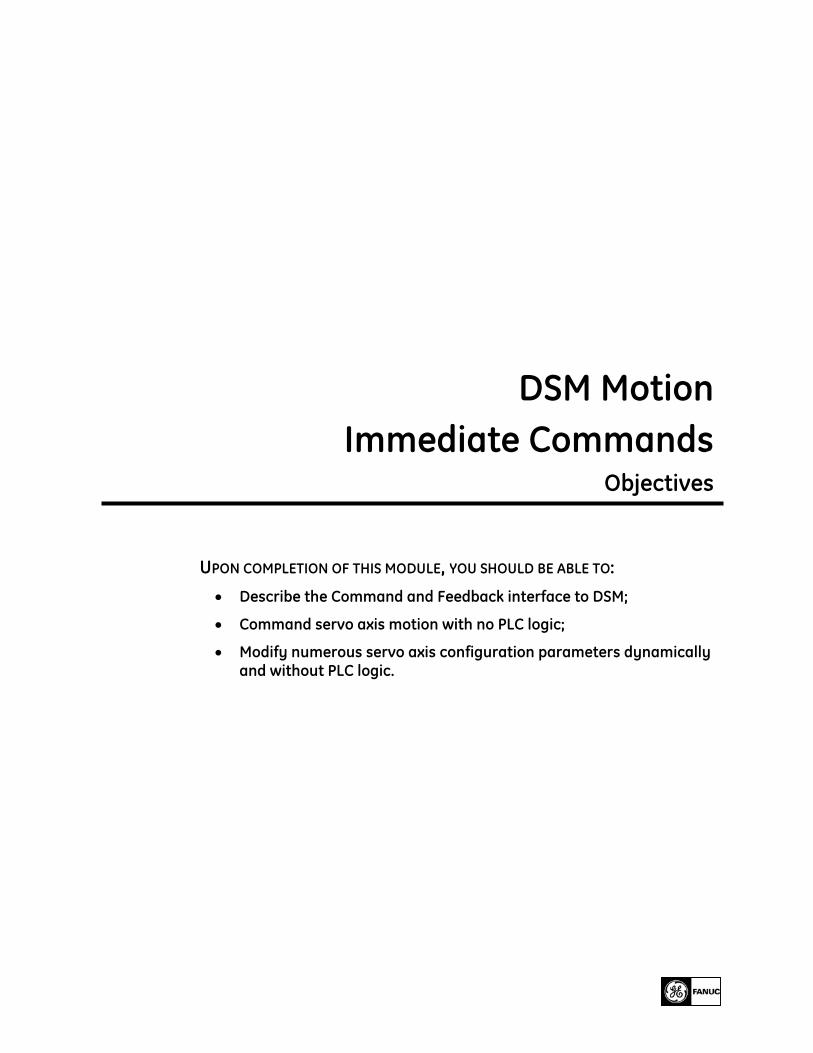
DSM Single Bit Motion Commands (%Q References) This lab makes use of the following command bits available for each DSM axis. In each case, the operator interface sets a bit mapped to the demo PLC %Q reference listed in the PLC Reference column.
Single Bit Command Demo PLC Reference Abort All Moves %Q00081 Feed Hold %Q00082 Enable Drive %Q00083 Find Home %Q00084 Jog Plus %Q00085 Jog Minus %Q00086
Table 1 - 1. DSM Axis Bit Commands
Additional single bit commands are available to clear fault conditions and initiate execution of each of the ten motion programs that can be stored in the DSM module. Stored motion programs are illustrated in a companion lab entitled “DSM Motion Program Variables”.
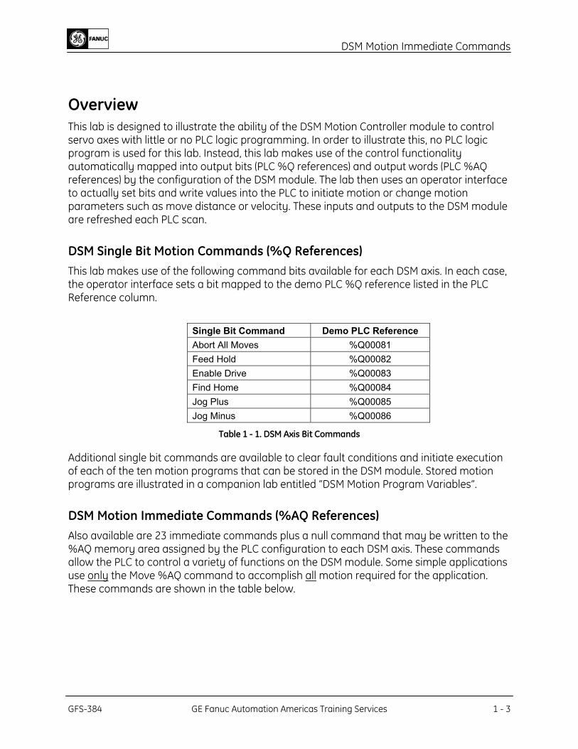
DSM Motion Immediate Commands (%AQ References) Also available are 23 immediate commands plus a null command that may be written to the %AQ memory area assigned by the PLC configuration to each DSM axis. These commands allow the PLC to control a variety of functions on the DSM module. Some simple applications use only the Move %AQ command to accomplish all motion required for the application. These commands are shown in the table below.
GFS-384 GE Fanuc Automation Americas Training Services 1 - 3
DSM Motion Immediate Commands
Command
Code (hex)
Description Command
Code (hex)
Description
00 Null 20 Feedrate Override 21 Position Increment (without position
update) 22 Move at Velocity
23 Set Position 25 Position Increment (with position update)
26 In Position Zone 27 Move Commands 28 Jog Velocity 29 Jog Acceleration 2A Position Loop Time Constant 2B Velocity Feedforward 2C Integrator time Constant 2D Follower A/B Ratio 2E Velocity Loop Gain 2F Torque Limit 31 Set Aux Encoder Position 34 Force Servo Velocity 40 Select Return Data 1 41 Select Return Data 2 42 Follower Ramp Distance Make-Up Time 47 Select Analog Output Mode 49 Clear New Configuration received 50 Load Parameter Immediate
Table 1 - 2. DSM %AQ Immediate Commands
DSM Single Bit Feedback (%I References) In addition to the %Q and %AQ command interface, each axis also has single bits mapped into %I references that give the PLC logic program critical information about the axis and motion status. The table below shows the various feedback bits and their %I reference locations in the demo system. Those in bold are used in the workshop operator interface screens to provide feedback on status of the axis.
Status Bit Function DEMO PLC REFERENCE Status Bit Function DEMO PLC REFERENCE Axis Enabled %I00081 Strobe 1 Flag %I00087 Position Valid %I00082 Strobe 2 Flag %I00088 Drive Enabled %I00083 Position Error Limit %I00089 Program Active %I00084 Torque Limit %I00090 Moving %I00085 Servo Ready %I00091 In Zone %I00086 Follower Enabled %I00093 Velocity Limit %I00094 Follower Ramp Active %I00095
Table 1 - 3. DSM %I Axis Status Bits
There are additional %I bits to indicate a module error has occurred and to give the status such as axis overtravel.
DSM Analog Data Feedback (%AI References) Each DSM axis provides analog data feedback mapped into the %AI references of the PLC. The following data for axis 1 is available at the addresses shown in the demo PLC. Those in bold are used in the lab operator interface screens to provide feedback on axis status. A
1 - 4 GE Fanuc Automation Americas Training Services GFS-384
DSM Motion Immediate Commands
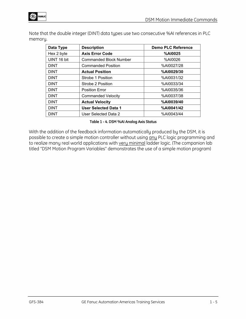
Note that the double integer (DINT) data types use two consecutive %AI references in PLC memory.
Data Type Description Demo PLC Reference Hex 2 byte Axis Error Code %AI0025 UINT 16 bit Commanded Block Number %AI0026 DINT Commanded Position %AI0027/28 DINT Actual Position %AI0029/30 DINT Strobe 1 Position %AI0031/32 DINT Strobe 2 Position %AI0033/34 DINT Position Error %AI0035/36 DINT Commanded Velocity %AI0037/38 DINT Actual Velocity %AI0039/40 DINT User Selected Data 1 %AI0041/42 DINT User Selected Data 2 %AI0043/44
Table 1 - 4. DSM %AI Analog Axis Status
With the addition of the feedback information automatically produced by the DSM, it is possible to create a simple motion controller without using any PLC logic programming and to realize many real world applications with very minimal ladder logic. (The companion lab titled “DSM Motion Program Variables” demonstrates the use of a simple motion program)
GFS-384 GE Fanuc Automation Americas Training Services 1 - 5
DSM Motion Immediate Commands
Lab Exercise – Command, Modify and Monitor Motion With No PLC Logic Program Lab Objectives: This exercise is designed to demonstrate how to:
• Command servo axis motion with no PLC logic program
• Modify numerous servo axis configuration parameters dynamically without PLC logic
• Monitor axis and motion status
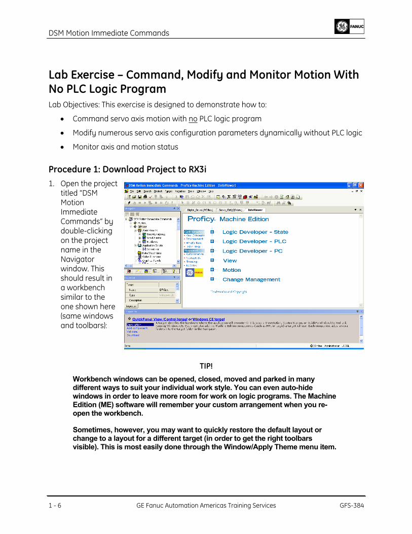
Procedure 1: Download Project to RX3i 1. Open the project
titled “DSM Motion Immediate Commands” by double-clicking on the project name in the Navigator window. This should result in a workbench similar to the one shown here (same windows and toolbars):
TIP!
Workbench windows can be opened, closed, moved and parked in many different ways to suit your individual work style. You can even auto-hide windows in order to leave more room for work on logic programs. The Machine Edition (ME) software will remember your custom arrangement when you re-open the workbench.
Sometimes, however, you may want to quickly restore the default layout or change to a layout for a different target (in order to get the right toolbars visible). This is most easily done through the Window/Apply Theme menu item.
1 - 6 GE Fanuc Automation Americas Training Services GFS-384
DSM Motion Immediate Commands
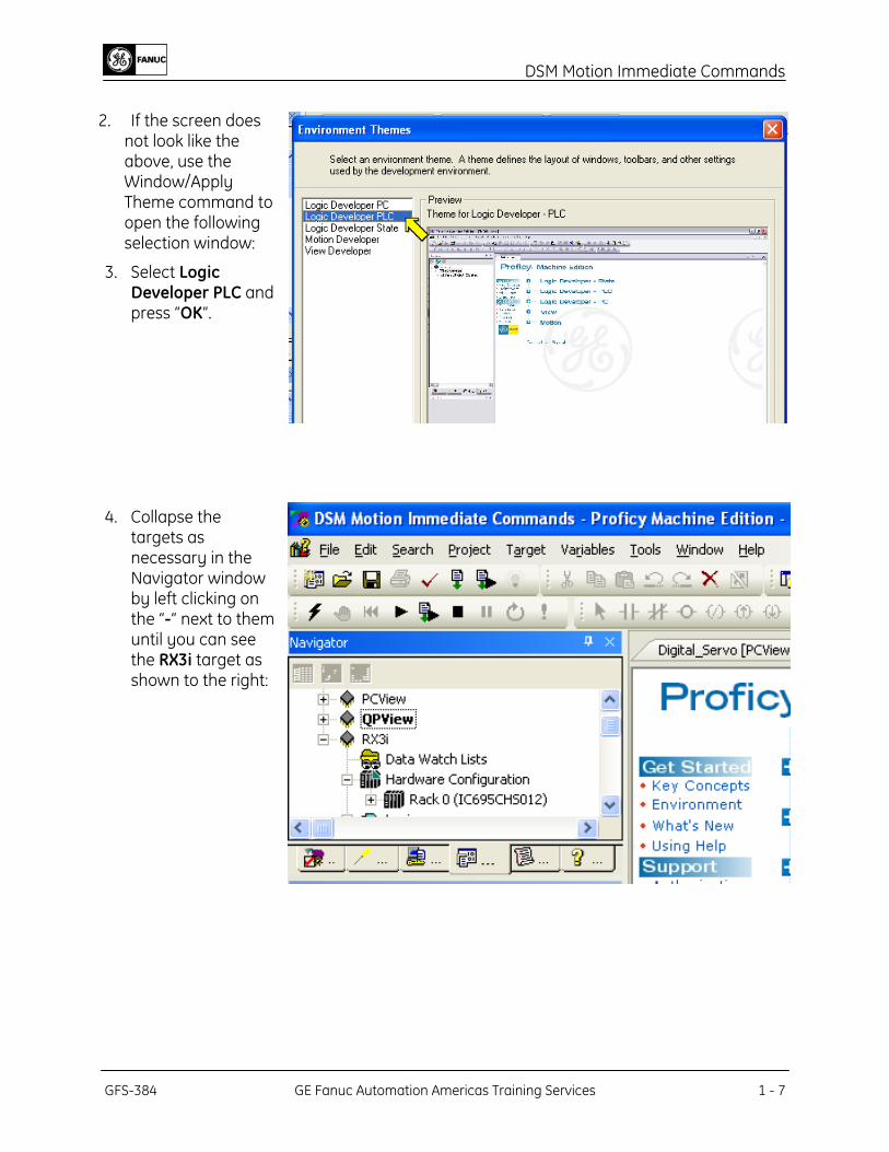
2. If the screen does
not look like the above, use the Window/Apply Theme command to open the following selection window:
3. Select Logic Developer PLC and press “OK”.
4. Collapse the targets as necessary in the Navigator window by left clicking on the “-“ next to them until you can see the RX3i target as shown to the right:
GFS-384 GE Fanuc Automation Americas Training Services 1 - 7
DSM Motion Immediate Commands
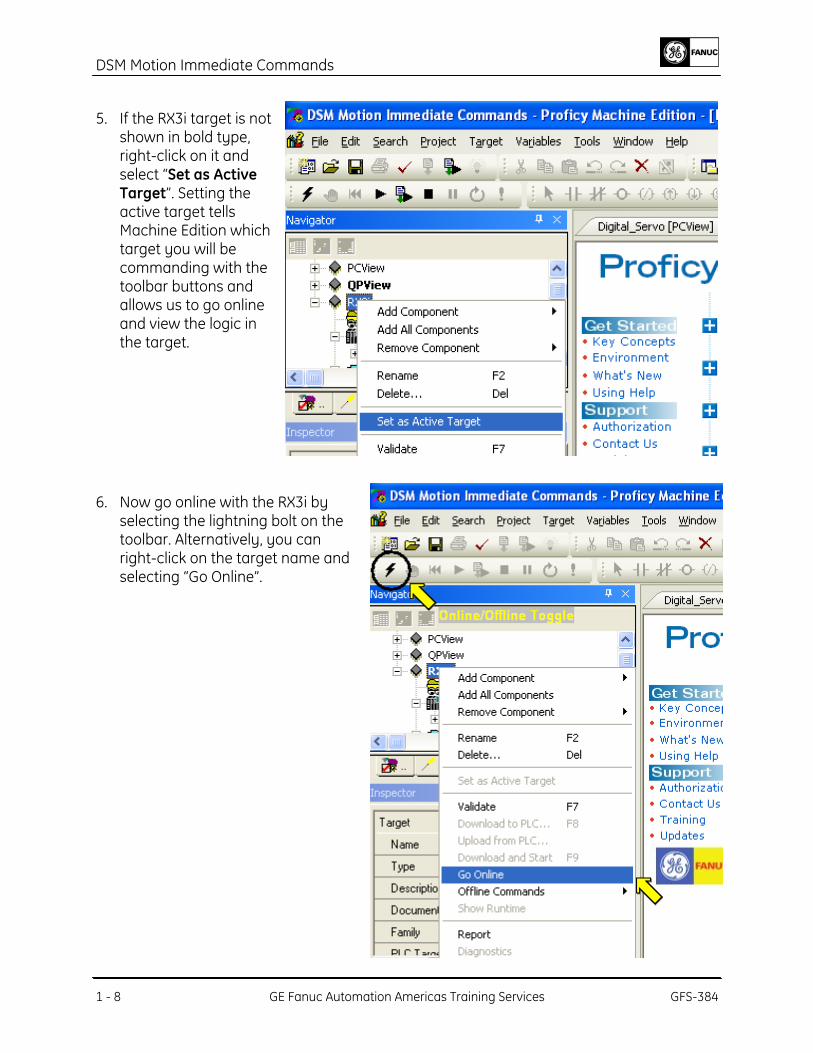
5. If the RX3i target is not shown in bold type, right-click on it and select “Set as Active Target”. Setting the active target tells Machine Edition which target you will be commanding with the toolbar buttons and allows us to go online and view the logic in the target.
6. Now go online with the RX3i by selecting the lightning bolt on the toolbar. Alternatively, you can right-click on the target name and selecting “Go Online”.
1 - 8 GE Fanuc Automation Americas Training Services GFS-384
DSM Motion Immediate Commands
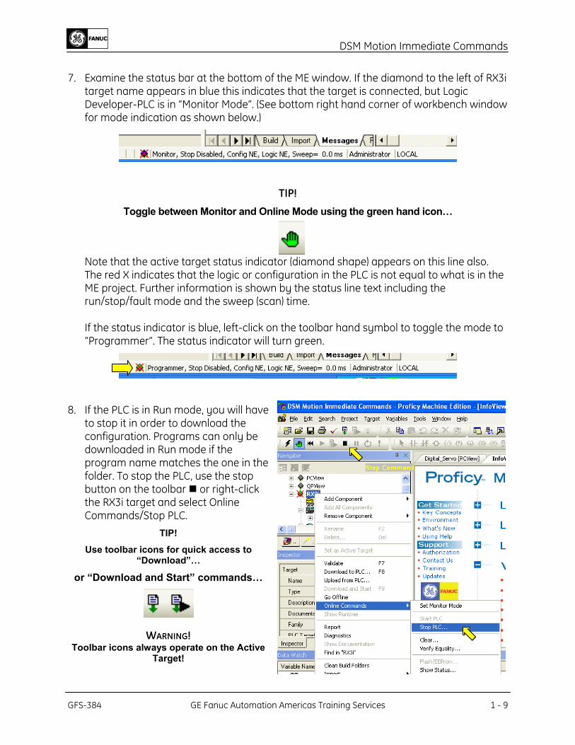
7. Examine the status bar at the bottom of the ME window. If the diamond to the left of RX3i
target name appears in blue this indicates that the target is connected, but Logic Developer-PLC is in “Monitor Mode”. (See bottom right hand corner of workbench window for mode indication as shown below.)
TIP!
Toggle between Monitor and Online Mode using the green hand icon…
Note that the active target status indicator (diamond shape) appears on this line also. The red X indicates that the logic or configuration in the PLC is not equal to what is in the ME project. Further information is shown by the status line text including the run/stop/fault mode and the sweep (scan) time. If the status indicator is blue, left-click on the toolbar hand symbol to toggle the mode to “Programmer”. The status indicator will turn green.
8. If the PLC is in Run mode, you will have to stop it in order to download the configuration. Programs can only be downloaded in Run mode if the program name matches the one in the folder. To stop the PLC, use the stop button on the toolbar or right-click the RX3i target and select Online Commands/Stop PLC.
TIP!
Use toolbar icons for quick access to “Download”…
or “Download and Start” commands…
WARNING! Toolbar icons always operate on the Active
Target!
GFS-384 GE Fanuc Automation Americas Training Services 1 - 9
DSM Motion Immediate Commands
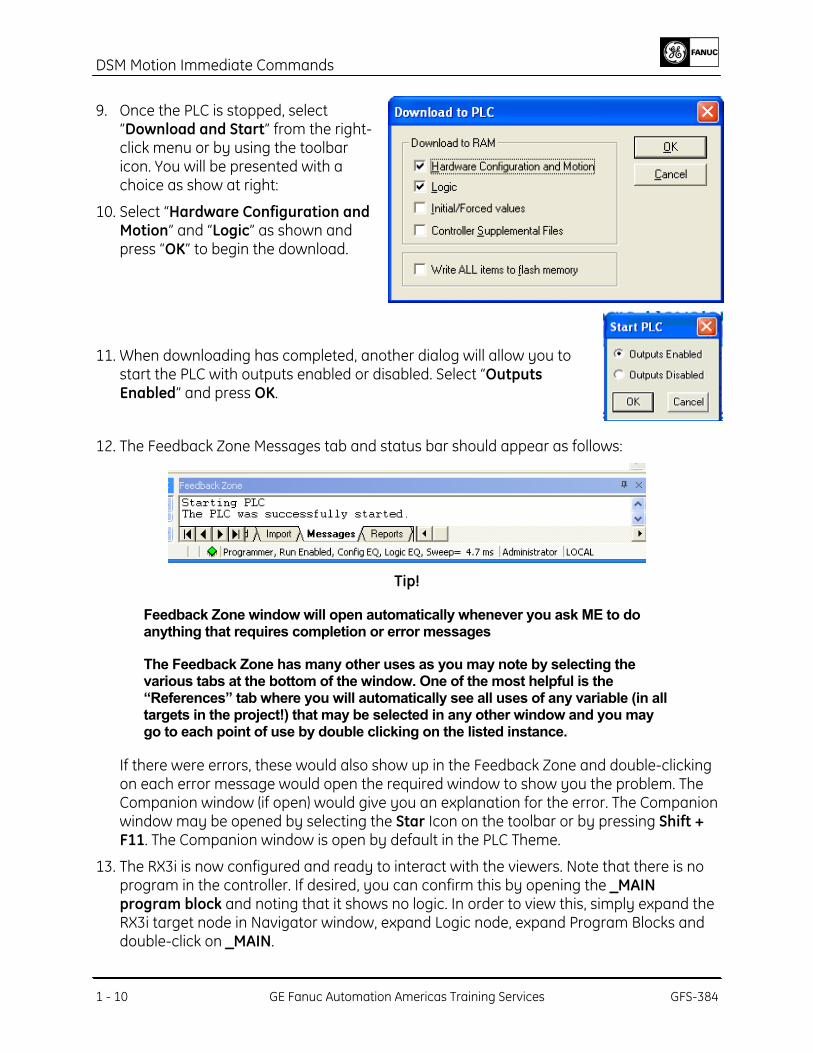
9. Once the PLC is stopped, select
“Download and Start” from the right-click menu or by using the toolbar icon. You will be presented with a choice as show at right:
10. Select “Hardware Configuration and Motion” and “Logic” as shown and press “OK” to begin the download.
11. When downloading has completed, another dialog will allow you to start the PLC with outputs enabled or disabled. Select “Outputs Enabled” and press OK.
12. The Feedback Zone Messages tab and status bar should appear as follows:
Tip!
Feedback Zone window will open automatically whenever you ask ME to do anything that requires completion or error messages
The Feedback Zone has many other uses as you may note by selecting the various tabs at the bottom of the window. One of the most helpful is the “References” tab where you will automatically see all uses of any variable (in all targets in the project!) that may be selected in any other window and you may go to each point of use by double clicking on the listed instance.
If there were errors, these would also show up in the Feedback Zone and double-clicking on each error message would open the required window to show you the problem. The Companion window (if open) would give you an explanation for the error. The Companion window may be opened by selecting the Star Icon on the toolbar or by pressing Shift + F11. The Companion window is open by default in the PLC Theme.
13. The RX3i is now configured and ready to interact with the viewers. Note that there is no program in the controller. If desired, you can confirm this by opening the _MAIN program block and noting that it shows no logic. In order to view this, simply expand the RX3i target node in Navigator window, expand Logic node, expand Program Blocks and double-click on _MAIN.
1 - 10 GE Fanuc Automation Americas Training Services GFS-384
DSM Motion Immediate Commands
The yellow lighting bolt indicates ME is online with the controller. If the logic displayed were not equal to the logic in the PLC, the lighting bolt would be joined by a not equal symbol.
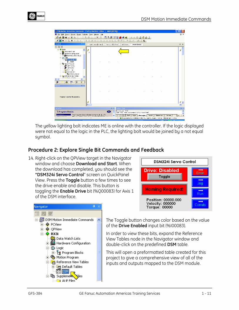
Procedure 2: Explore Single Bit Commands and Feedback 14. Right-click on the QPView target in the Navigator
window and choose Download and Start. When the download has completed, you should see the “DSM324i Servo Control” screen on QuickPanel View. Press the Toggle button a few times to see the drive enable and disable. This button is toggling the Enable Drive bit (%Q00083) for Axis 1 of the DSM interface.
The Toggle button changes color based on the value of the Drive Enabled input bit (%I00083).
In order to view these bits, expand the Reference View Tables node in the Navigator window and double-click on the predefined DSM table.
This will open a preformatted table created for this project to give a comprehensive view of all of the inputs and outputs mapped to the DSM module.
GFS-384 GE Fanuc Automation Americas Training Services 1 - 11
DSM Motion Immediate Commands
TIP!
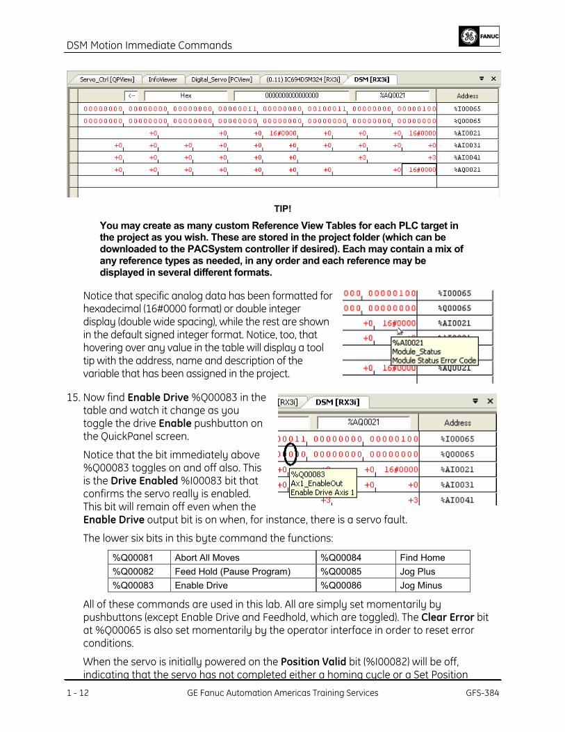
You may create as many custom Reference View Tables for each PLC target in the project as you wish. These are stored in the project folder (which can be downloaded to the PACSystem controller if desired). Each may contain a mix of any reference types as needed, in any order and each reference may be displayed in several different formats.
Notice that specific analog data has been formatted for hexadecimal (16#0000 format) or double integer display (double wide spacing), while the rest are shown in the default signed integer format. Notice, too, that hovering over any value in the table will display a tool tip with the address, name and description of the variable that has been assigned in the project.
15. Now find Enable Drive %Q00083 in the table and watch it change as you toggle the drive Enable pushbutton on the QuickPanel screen.
Notice that the bit immediately above %Q00083 toggles on and off also. This is the Drive Enabled %I00083 bit that confirms the servo really is enabled. This bit will remain off even when the Enable Drive output bit is on when, for instance, there is a servo fault.
The lower six bits in this byte command the functions:
%Q00081 Abort All Moves %Q00084 Find Home %Q00082 Feed Hold (Pause Program) %Q00085 Jog Plus %Q00083 Enable Drive %Q00086 Jog Minus
All of these commands are used in this lab. All are simply set momentarily by pushbuttons (except Enable Drive and Feedhold, which are toggled). The Clear Error bit at %Q00065 is also set momentarily by the operator interface in order to reset error conditions.
1 - 12 GE Fanuc Automation Americas Training Services GFS-384
When the servo is initially powered on the Position Valid bit (%I00082) will be off, indicating that the servo has not completed either a homing cycle or a Set Position
DSM Motion Immediate Commands
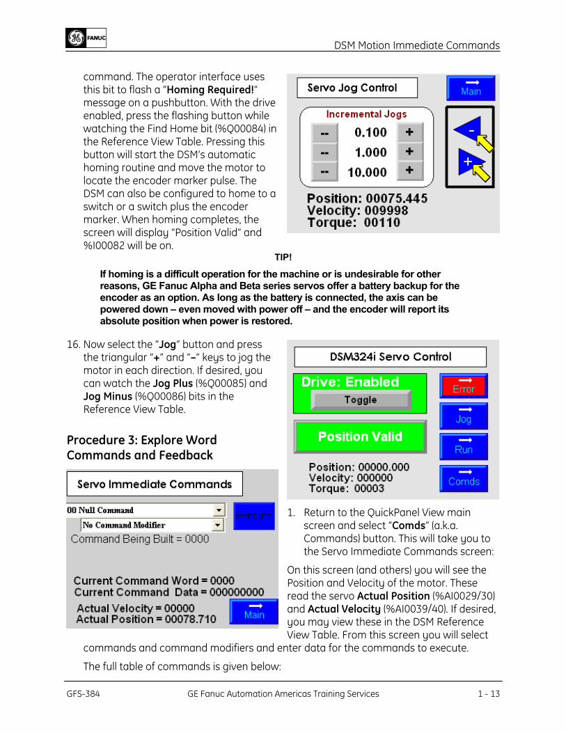
command. The operator interface uses this bit to flash a “Homing Required!” message on a pushbutton. With the drive enabled, press the flashing button while watching the Find Home bit (%Q00084) in the Reference View Table. Pressing this button will start the DSM’s automatic homing routine and move the motor to locate the encoder marker pulse. The DSM can also be configured to home to a switch or a switch plus the encoder marker. When homing completes, the screen will display “Position Valid” and %I00082 will be on.
TIP!
If homing is a difficult operation for the machine or is undesirable for other reasons, GE Fanuc Alpha and Beta series servos offer a battery backup for the encoder as an option. As long as the battery is connected, the axis can be powered down – even moved with power off – and the encoder will report its absolute position when power is restored.
16. Now select the “Jog” button and press the triangular “+” and “–“ keys to jog the motor in each direction. If desired, you can watch the Jog Plus (%Q00085) and Jog Minus (%Q00086) bits in the Reference View Table.
Procedure 3: Explore Word Commands and Feedback
1. Return to the QuickPanel View main screen and select “Comds” (a.k.a. Commands) button. This will take you to the Servo Immediate Commands screen:
On this screen (and others) you will see the Position and Velocity of the motor. These read the servo Actual Position (%AI0029/30) and Actual Velocity (%AI0039/40). If desired, you may view these in the DSM Reference View Table. From this screen you will select
commands and command modifiers and enter data for the commands to execute.
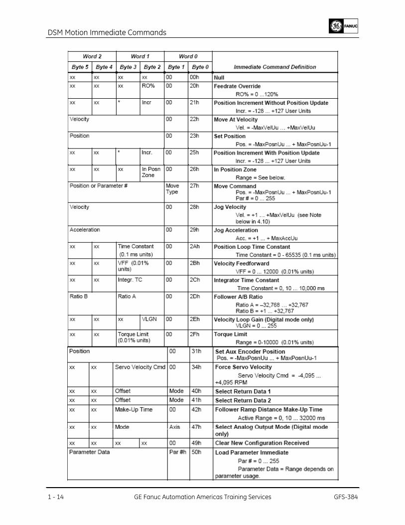
The full table of commands is given below:
GFS-384 GE Fanuc Automation Americas Training Services 1 - 13
DSM Motion Immediate Commands
1 - 14 GE Fanuc Automation Americas Training Services GFS-384
DSM Motion Immediate Commands
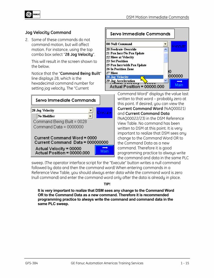
Jog Velocity Command 2. Some of these commands do not
command motion, but will affect motion. For instance, using the top combo box select “28 Jog Velocity”.
This will result in the screen shown to the below.
Notice that the “Command Being Built” line displays 28, which is the hexadecimal command number for setting jog velocity. The “Current
Command Word” displays the value last written to that word – probably zero at this point. If desired, you can view the Current Command Word (%AQ00021) and Current Command Data (%AQ00022/23) in the DSM Reference View Table. No command has been written to DSM at this point. It is very important to realize that DSM sees any change to the Command Word OR to the Command Data as a new command. Therefore it is good programming practice to always write the command and data in the same PLC
sweep. (The operator interface script for the “Execute” button writes a null command followed by data and then the command word) When entering commands in a Reference View Table, you should always enter data while the command word is zero (null command) and enter the command word only after the data is already in place.
TIP!
It is very important to realize that DSM sees any change to the Command Word OR to the Command Data as a new command. Therefore it is recommended programming practice to always write the command and command data in the same PLC sweep.
GFS-384 GE Fanuc Automation Americas Training Services 1 - 15
DSM Motion Immediate Commands
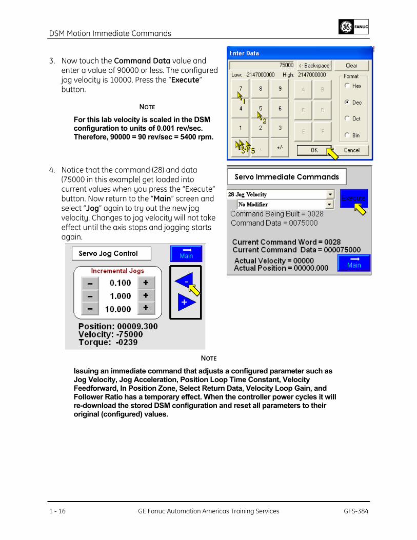
3. Now touch the Command Data value and enter a value of 90000 or less. The configured jog velocity is 10000. Press the “Execute” button.
NOTE
For this lab velocity is scaled in the DSM configuration to units of 0.001 rev/sec. Therefore, 90000 = 90 rev/sec = 5400 rpm.
4. Notice that the command (28) and data (75000 in this example) get loaded into current values when you press the “Execute” button. Now return to the “Main” screen and select “Jog” again to try out the new jog velocity. Changes to jog velocity will not take effect until the axis stops and jogging starts again.
NOTE
Issuing an immediate command that adjusts a configured parameter such as Jog Velocity, Jog Acceleration, Position Loop Time Constant, Velocity Feedforward, In Position Zone, Select Return Data, Velocity Loop Gain, and Follower Ratio has a temporary effect. When the controller power cycles it will re-download the stored DSM configuration and reset all parameters to their original (configured) values.
1 - 16 GE Fanuc Automation Americas Training Services GFS-384
DSM Motion Immediate Commands
5. Many other commands also adjust configured axis parameters. You may wish to try the
Jog Acceleration command to see its affect on the jog operation. The configured value is 500000. Try changing the value to 50000 or 2000000 to see the effect on jog performance.
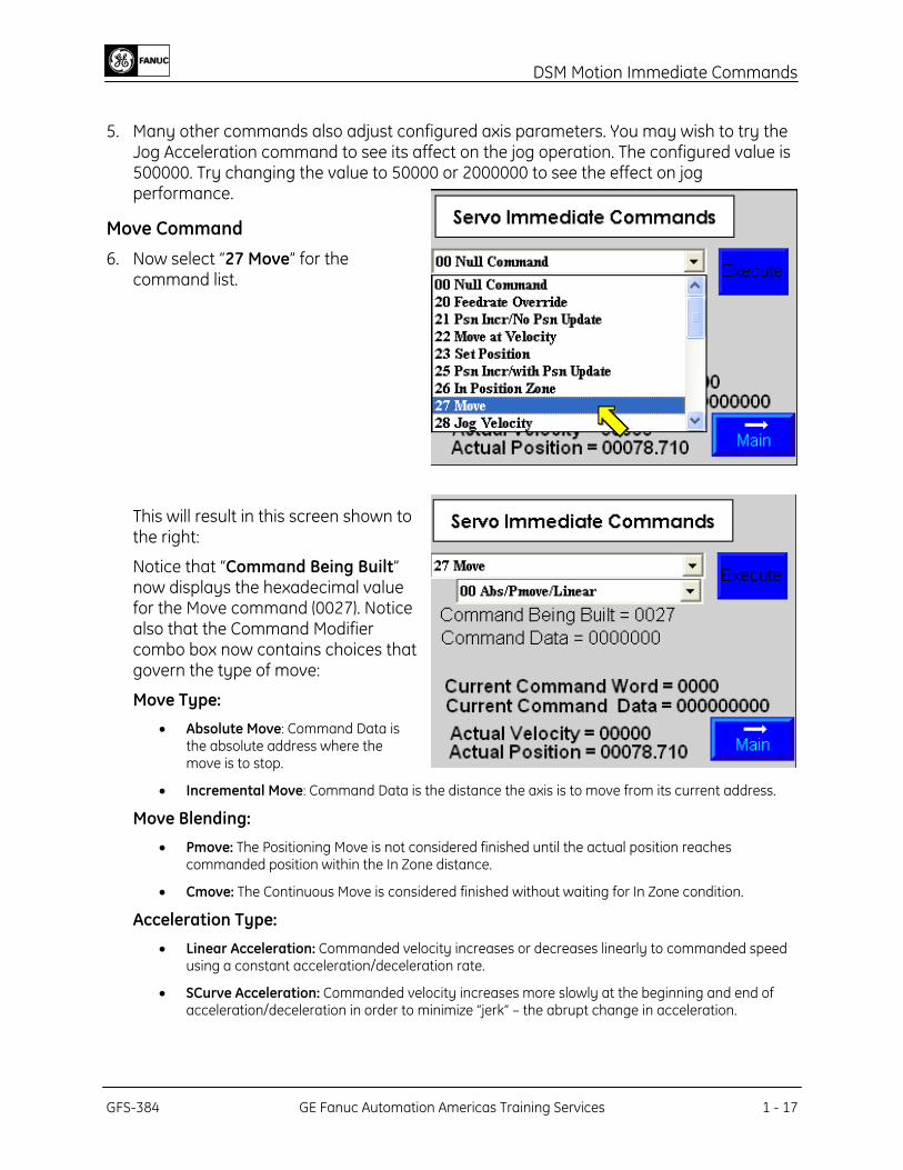
Move Command 6. Now select “27 Move” for the
command list.
This will result in this screen shown to the right:
Notice that “Command Being Built” now displays the hexadecimal value for the Move command (0027). Notice also that the Command Modifier combo box now contains choices that govern the type of move:
Move Type:
• Absolute Move: Command Data is the absolute address where the move is to stop.
• Incremental Move: Command Data is the distance the axis is to move from its current address.
Move Blending:
• Pmove: The Positioning Move is not considered finished until the actual position reaches commanded position within the In Zone distance.
• Cmove: The Continuous Move is considered finished without waiting for In Zone condition.
Acceleration Type:
• Linear Acceleration: Commanded velocity increases or decreases linearly to commanded speed using a constant acceleration/deceleration rate.
• SCurve Acceleration: Commanded velocity increases more slowly at the beginning and end of acceleration/deceleration in order to minimize “jerk” – the abrupt change in acceleration.
GFS-384 GE Fanuc Automation Americas Training Services 1 - 17
DSM Motion Immediate Commands
NOTE
Attempting to execute a new move before the first one completes will cause an error condition that must be cleared before you proceed. When the move is finished (In Program bit returns to zero) the next move command may be issued. If you force an error go to the Error screen and press Clear Error.
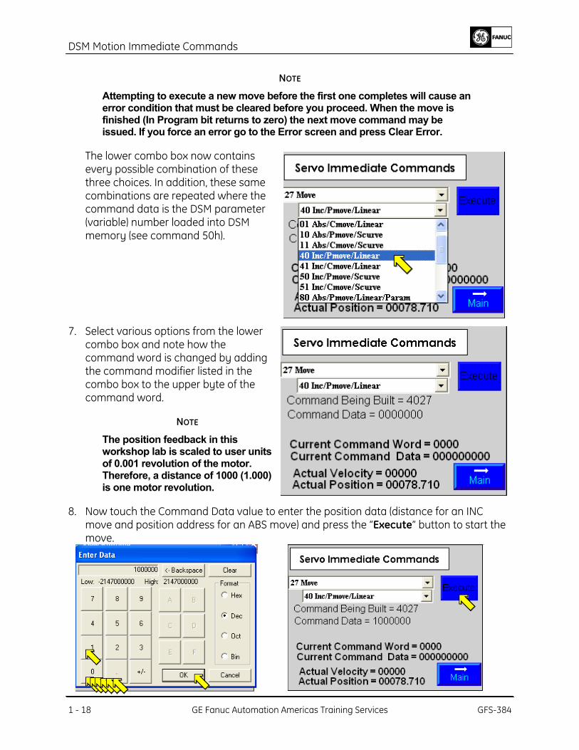
The lower combo box now contains every possible combination of these three choices. In addition, these same combinations are repeated where the command data is the DSM parameter (variable) number loaded into DSM memory (see command 50h).
7. Select various options from the lower combo box and note how the command word is changed by adding the command modifier listed in the combo box to the upper byte of the command word.
NOTE
The position feedback in this workshop lab is scaled to user units of 0.001 revolution of the motor. Therefore, a distance of 1000 (1.000) is one motor revolution.
8. Now touch the Command Data value to enter the position data (distance for an INC move and position address for an ABS move) and press the “Execute” button to start the move.
1 - 18 GE Fanuc Automation Americas Training Services GFS-384
DSM Motion Immediate Commands
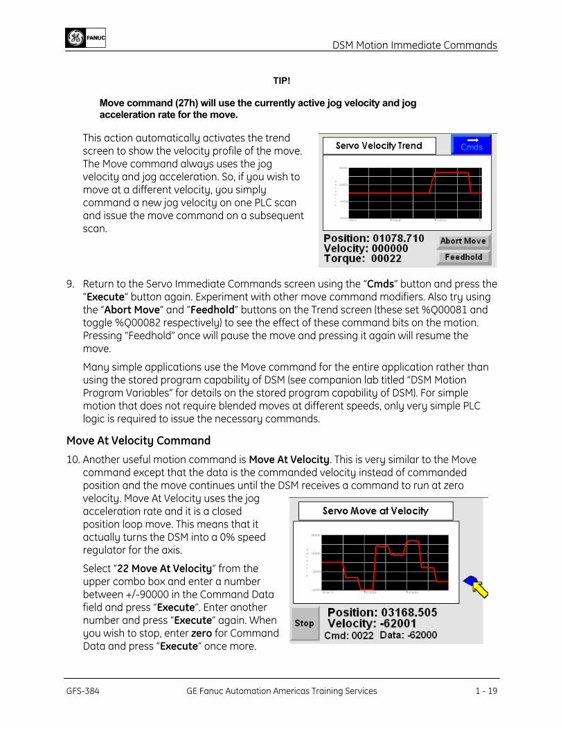
TIP!
Move command (27h) will use the currently active jog velocity and jog acceleration rate for the move.
This action automatically activates the trend screen to show the velocity profile of the move. The Move command always uses the jog velocity and jog acceleration. So, if you wish to move at a different velocity, you simply command a new jog velocity on one PLC scan and issue the move command on a subsequent scan.
9. Return to the Servo Immediate Commands screen using the “Cmds” button and press the “Execute” button again. Experiment with other move command modifiers. Also try using the “Abort Move” and “Feedhold” buttons on the Trend screen (these set %Q00081 and toggle %Q00082 respectively) to see the effect of these command bits on the motion. Pressing “Feedhold” once will pause the move and pressing it again will resume the move.
Many simple applications use the Move command for the entire application rather than using the stored program capability of DSM (see companion lab titled “DSM Motion Program Variables” for details on the stored program capability of DSM). For simple motion that does not require blended moves at different speeds, only very simple PLC logic is required to issue the necessary commands.
Move At Velocity Command 10. Another useful motion command is Move At Velocity. This is very similar to the Move
command except that the data is the commanded velocity instead of commanded position and the move continues until the DSM receives a command to run at zero velocity. Move At Velocity uses the jog acceleration rate and it is a closed position loop move. This means that it actually turns the DSM into a 0% speed regulator for the axis.
Select “22 Move At Velocity” from the upper combo box and enter a number between +/-90000 in the Command Data field and press “Execute”. Enter another number and press “Execute” again. When you wish to stop, enter zero for Command Data and press “Execute” once more.
GFS-384 GE Fanuc Automation Americas Training Services 1 - 19
DSM Motion Immediate Commands
11. For another view of this command in action, return to the main screen and select the
“Run” button. Now try moving the slider on the right side of the trend screen up and down and watch the command data change.
12. When you are finished, press the “Stop” button and then the “Return” button to return to the main screen.
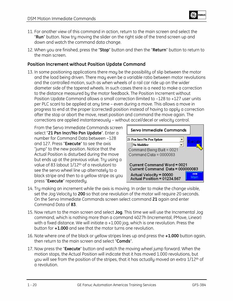
Position Increment without Position Update Command 13. In some positioning applications there may be the possibility of slip between the motor
and the load being driven. There may even be a variable ratio between motor revolutions and the controlled motion, such as when wheels of a rail car ride up on the wider diameter side of the tapered wheels. In such cases there is a need to make a correction to the distance measured by the motor feedback. The Position Increment without Position Update Command allows a small correction (limited to –128 to +127 user units per PLC scan) to be applied at any time – even during a move. This allows a move in progress to end at the proper (corrected) position instead of having to apply a correction after the stop or abort the move, reset position and command the move again. The corrections are applied instantaneously – without accel/decel or velocity control.
From the Servo Immediate Commands screen select “21 Psn Incr/No Psn Update”. Enter a number for Command Data between –128 and 127. Press “Execute” to see the axis “jump” to the new position. Notice that the Actual Position is disturbed during the move but ends up at the previous value. Try using a value of 83 (about 1/12th of a revolution) to see the servo wheel line up alternately to a black stripe and then to a yellow stripe as you press “Execute” repeatedly.
14. Try making an increment while the axis is moving. In order to make the change visible, set the Jog Velocity to 200 so that one revolution of the motor will require 20 seconds. On the Servo Immediate Commands screen select command 21 again and enter Command Data of 83.
15. Now return to the main screen and select Jog. This time we will use the Incremental Jog command, which is nothing more than a command 4027h (Incremental, PMove, Linear) with a fixed distance. We will initiate a +1.000 jog, which is one revolution. Press the button for +1.000 and see that the motor turns one revolution.
16. Note where one of the black or yellow stripes lines up and press the +1.000 button again, then return to the main screen and select “Comds”.
17. Now press the “Execute” button and watch the moving wheel jump forward. When the motion stops, the Actual Position will indicate that it has moved 1.000 revolutions, but you will see from the position of the stripes, that it has actually moved an extra 1/12th of a revolution.
1 - 20 GE Fanuc Automation Americas Training Services GFS-384
DSM Motion Immediate Commands
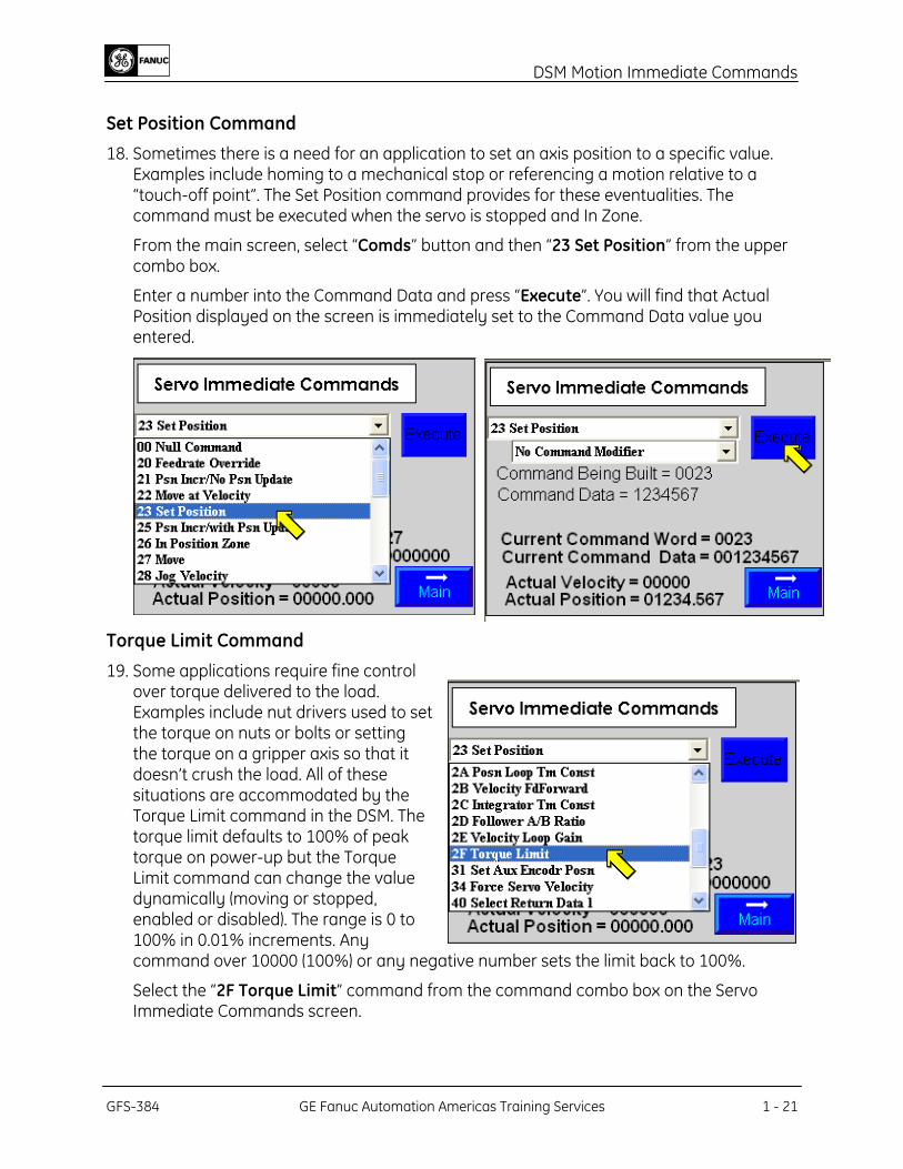
Set Position Command 18. Sometimes there is a need for an application to set an axis position to a specific value.
Examples include homing to a mechanical stop or referencing a motion relative to a “touch-off point”. The Set Position command provides for these eventualities. The command must be executed when the servo is stopped and In Zone.
From the main screen, select “Comds” button and then “23 Set Position” from the upper combo box.
Enter a number into the Command Data and press “Execute”. You will find that Actual Position displayed on the screen is immediately set to the Command Data value you entered.
Torque Limit Command 19. Some applications require fine control
over torque delivered to the load. Examples include nut drivers used to set the torque on nuts or bolts or setting the torque on a gripper axis so that it doesn’t crush the load. All of these situations are accommodated by the Torque Limit command in the DSM. The torque limit defaults to 100% of peak torque on power-up but the Torque Limit command can change the value dynamically (moving or stopped, enabled or disabled). The range is 0 to 100% in 0.01% increments. Any command over 10000 (100%) or any negative number sets the limit back to 100%.
Select the “2F Torque Limit” command from the command combo box on the Servo Immediate Commands screen.
GFS-384 GE Fanuc Automation Americas Training Services 1 - 21
DSM Motion Immediate Commands
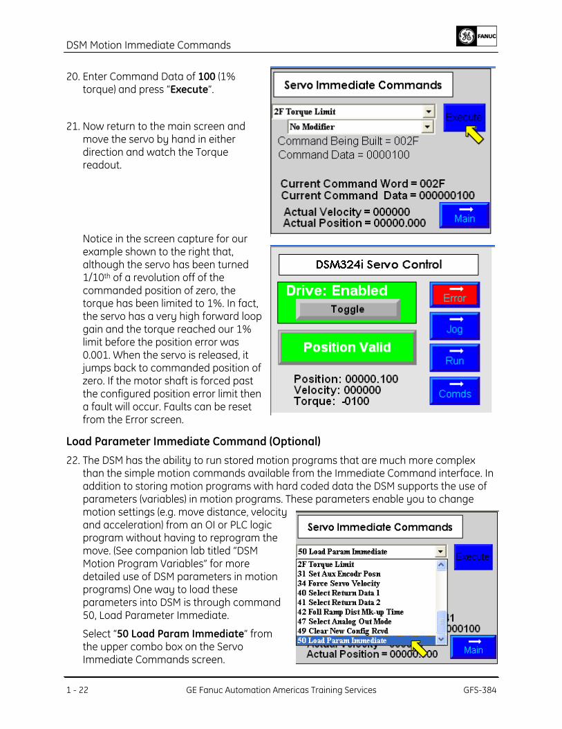
20. Enter Command Data of 100 (1%
torque) and press “Execute”.
21. Now return to the main screen and move the servo by hand in either direction and watch the Torque readout.
Notice in the screen capture for our example shown to the right that, although the servo has been turned 1/10th of a revolution off of the commanded position of zero, the torque has been limited to 1%. In fact, the servo has a very high forward loop gain and the torque reached our 1% limit before the position error was 0.001. When the servo is released, it jumps back to commanded position of zero. If the motor shaft is forced past the configured position error limit then a fault will occur. Faults can be reset from the Error screen.
Load Parameter Immediate Command (Optional) 22. The DSM has the ability to run stored motion programs that are much more complex
than the simple motion commands available from the Immediate Command interface. In addition to storing motion programs with hard coded data the DSM supports the use of parameters (variables) in motion programs. These parameters enable you to change motion settings (e.g. move distance, velocity and acceleration) from an OI or PLC logic program without having to reprogram the move. (See companion lab titled “DSM Motion Program Variables” for more detailed use of DSM parameters in motion programs) One way to load these parameters into DSM is through command 50, Load Parameter Immediate.
Select “50 Load Param Immediate” from the upper combo box on the Servo Immediate Commands screen.
1 - 22 GE Fanuc Automation Americas Training Services GFS-384
DSM Motion Immediate Commands
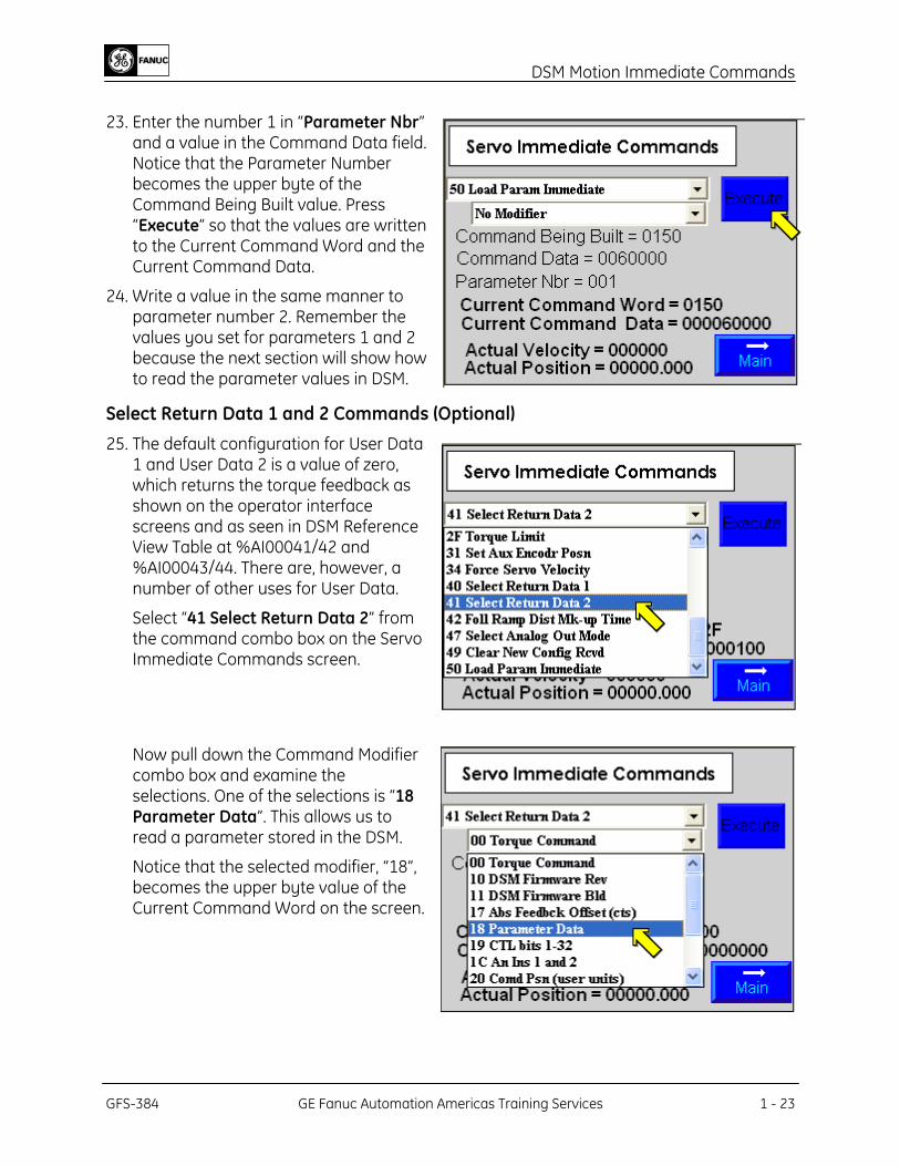
23. Enter the number 1 in “Parameter Nbr”
and a value in the Command Data field. Notice that the Parameter Number becomes the upper byte of the Command Being Built value. Press “Execute” so that the values are written to the Current Command Word and the Current Command Data.
24. Write a value in the same manner to parameter number 2. Remember the values you set for parameters 1 and 2 because the next section will show how to read the parameter values in DSM.
Select Return Data 1 and 2 Commands (Optional) 25. The default configuration for User Data
1 and User Data 2 is a value of zero, which returns the torque feedback as shown on the operator interface screens and as seen in DSM Reference View Table at %AI00041/42 and %AI00043/44. There are, however, a number of other uses for User Data.
Select “41 Select Return Data 2” from the command combo box on the Servo Immediate Commands screen.
Now pull down the Command Modifier combo box and examine the selections. One of the selections is “18 Parameter Data”. This allows us to read a parameter stored in the DSM.
Notice that the selected modifier, “18”, becomes the upper byte value of the Current Command Word on the screen.
GFS-384 GE Fanuc Automation Americas Training Services 1 - 23
DSM Motion Immediate Commands
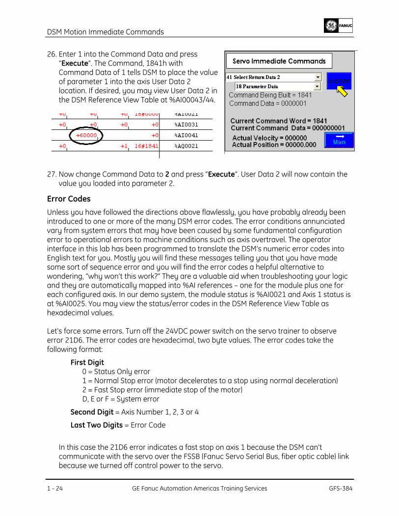
26. Enter 1 into the Command Data and press
“Execute”. The Command, 1841h with Command Data of 1 tells DSM to place the value of parameter 1 into the axis User Data 2 location. If desired, you may view User Data 2 in the DSM Reference View Table at %AI00043/44.
27. Now change Command Data to 2 and press “Execute”. User Data 2 will now contain the
value you loaded into parameter 2.
Error Codes Unless you have followed the directions above flawlessly, you have probably already been introduced to one or more of the many DSM error codes. The error conditions annunciated vary from system errors that may have been caused by some fundamental configuration error to operational errors to machine conditions such as axis overtravel. The operator interface in this lab has been programmed to translate the DSM’s numeric error codes into English text for you. Mostly you will find these messages telling you that you have made some sort of sequence error and you will find the error codes a helpful alternative to wondering, “why won’t this work?” They are a valuable aid when troubleshooting your logic and they are automatically mapped into %AI references – one for the module plus one for each configured axis. In our demo system, the module status is %AI0021 and Axis 1 status is at %AI0025. You may view the status/error codes in the DSM Reference View Table as hexadecimal values. Let’s force some errors. Turn off the 24VDC power switch on the servo trainer to observe error 21D6. The error codes are hexadecimal, two byte values. The error codes take the following format:
First Digit 0 = Status Only error 1 = Normal Stop error (motor decelerates to a stop using normal deceleration) 2 = Fast Stop error (immediate stop of the motor) D, E or F = System error
Second Digit = Axis Number 1, 2, 3 or 4
Last Two Digits = Error Code
In this case the 21D6 error indicates a fast stop on axis 1 because the DSM can’t communicate with the servo over the FSSB (Fanuc Servo Serial Bus, fiber optic cable) link because we turned off control power to the servo.
1 - 24 GE Fanuc Automation Americas Training Services GFS-384
DSM Motion Immediate Commands
GFS-384 GE Fanuc Automation Americas Training Services 1 - 25
28. Turn the 24 VDC Power switch back on and press the “Clear Error” button. (This sets the Clear Error bit, %Q00065 and also will clear the Module Error bit, %I00065.
29. Now turn off the 220VAC switch and try to jog the servo. Now you will get the 21B3 error, “Low Voltage DC LINK”. As the servo motor began to draw power from the bus, the servo amplifier detected a low voltage condition and transmitted that information (about an error in the servo amplifier, not in the DSM module). To clear this error in the servo amplifier, you must first cycle 24VDC power again. Then you may press the “Clear Error” button to clear the DSM error.
30. To illustrate an example of a command sequence error, try disabling the drive and pressing the “Homing Required!” button. You will immediately get the 0130 error, which says “Find Home while Drive Not Enabled error”. This is obviously either an operator error or a logical sequence error (if we actually had any logic in the PLC). Clear the error and return to the main screen again.
31. Try another sequence error (by far the most common type while you are troubleshooting logic). With the drive disabled, go to the Servo Immediate Commands screen and issue a Move command. If you have not yet homed the axis you will get error 0186 “Execute Program while Position Valid not set”. If your Position Valid bit (%I00082) is set, you will get error 0187 “Execute Program while Drive Enabled not set”.
You get the idea . . . Many of these “cockpit” errors would be very difficult to find. You would most likely sit there scratching your head for a considerable time before realizing that you hadn’t met all of the pre-conditions for issuing the command you just gave the DSM. It can, however, be very easy to program against such errors because the DSM provides %I bits to inform you about its readiness to receive commands. There are bits to indicate Drive Enabled, Position Valid, Axis Moving, Axis In Zone, and Program Active. These can be used to interlock against inappropriate operator action or to make sure an action sequence is finished before commanding the next.
Review This lab has attempted to demonstrate some of the features of DSM that make it an autonomous motion controller in a PLC backplane. Its interface features, while integrated much more fully into the PLC than a typical stand-alone controller, nevertheless have the capability to perform complete servo motion control actions that are not dependent on PLC CPU scan time or PLC logic. At the same time, the integration into the PLC I/O structure automatically gives the PLC complete information and control of the servo when that is required.
You should now be able to:
• Describe the Command and Feedback interface to DSM.
• Command servo axis motion with no PLC logic.
• Modify numerous servo axis configuration parameters dynamically and without PLC logic.