Embed Size (px)
Citation preview
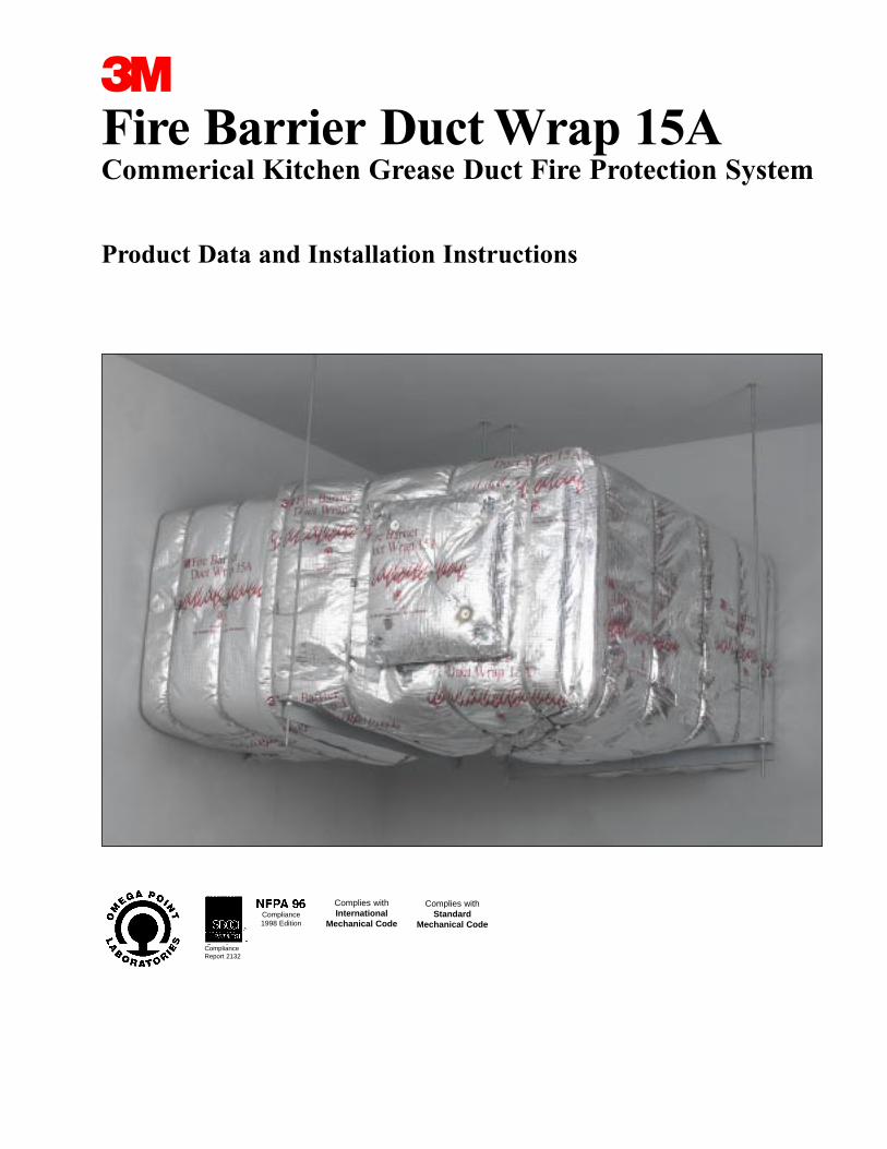
Fire Barrier Duct Wrap 15ACommerical Kitchen Grease Duct Fire Protection System
Product Data and Installation Instructions
3
ComplianceReport 2132
Compliance1998 Edition
Complies withInternational
Mechanical Code
Complies withStandard
Mechanical Code
1. Product Description3MTM Fire Barrier Duct Wrap 15A is a fire resistantwrap consisting of a patented inorganic blanketencapsulated with a scrim-reinforced foil. It is used tofire rate commercial kitchen grease ducts and is aproven alternative to 1 or 2 hour fire resistant ratedshaft enclosures. This non-asbestos wrap contains asafer fiber construction* and installs easily because ofits high flexibility and strength. 3M Fire Barrier DuctWrap 15A is the thinnest standard, single layer fireresistant wrap that has passed the UL1978 test whichsimulates a grease duct fire. With its excellent insulating capabilities, it is an ideal choice for tightspaces because it protects combustible constructionsat zero clearance to the overlap or collar. 3M FireBarrier 1000 N/S, 1003 S/L and 2000+ SiliconeSealants used in combination 3M Fire Barrier DuctWrap 15A provide an effective firestop when the ductpenetrates fire rated walls and floors.
Features
• Thinnest, standard one layer wrap for grease ductsrated as a shaft alternative per UL 1978
• Zero clearance to the overlap or collar for congested spaces
• High flexibility for installation ease
• Foil encapsulated with unique center overlap seamfor blanket protection, less dust, and high wrapstrength
• Safer fiber construction*
*Has been demonstrated to be soluble in the lungs according toEU guidelines 67/548/EWG, Note Q for bio persistence.
2. Applications3M Fire Barrier Duct Wrap 15A is an ideal fire resistive enclosure for commercial kitchen greaseducts. It is a proven performance alternative to a 1 or 2 hour fire resistant rated shaft enclosures and provides zero clearance to combustible constructionat overlap or collar. 3M Fire Barrier 1000 N/S, 1003S/L or 2000+ Silicone Sealant is used in combinationwith 3M Fire Barrier Duct Wrap 15A to firestop theduct when the duct penetrates fire rated floors andwalls.
4. Typical Physical PropertiesBlanket Color: gray/greenWeight: 1.38 lbs./sq. ft. (6.73 kg/sq. m)
5. Performance3M Fire Barrier Duct Wrap 15A has been tested inaccordance with the following:
ASTM C 411ASTM C 51ASTM E 84ASTM E 119ASTM E 136ASTM E 814UL 1978 (Sections 12 & 13)
Surface Burning Characteristics (ASTM E 84)Foil Encapsulated Blanket:
Flame Spread: 0Smoke Developed: 0
Blanket:Flame Spread: 0Smoke Developed: 0
For technical data and properties of 3M Fire Barrier1000 N/S, 1003 S/L and 2000+ Silicone Sealants seeseparate product data sheets available from your 3Mrepresentative
Code Compliance3M Fire Barrier Duct Wrap 15A complies with requirements of the following codes:
NFPA 96, 1998 EditionStandard Mechanical CodeInternational Mechanical CodeStandard Building CodeSBCCI Compliance Report 2132
This is only a partial list of code compliance. For thelatest code and approval information go towww.3m.com/firestop or speak to your authorized 3Mdistributor or sales representative at (800) 328-1687.
6. Installation Techniques3M Fire Barrier Duct Wrap 15A system should beinstalled in accordance with the following installationinstructions.
3. Availability
Product Unit Size Units/ Wt./ctn. ctn.
3M Fire Barrier Roll 1.5 in.x 24 in. x 20 ft. 1 53 lbs.Duct Wrap 15A (38mm x 60,9cm x 609 cm) 24 kg3M Fire Barrier Roll 1.5 in. x 48 in. x 20 ft. 1 106 lbs.Duct Wrap 15A (38mm x 121 cm x 609 cm) 48 kg
Thermal ConductivityTemperature OF (OC) btu•in./(hr.•ft2•F)500 (260) 0.4171000 (537) 0.9221500 (815) 1.691800 (982) 2.27
Grease Duct ListingsFire Enclosure System Omega Point Lab. Design Nos.Resistive Duct System Through-Rating Penetration
System1 or 2 hours GD 532 F FS 557 W
FS 558 FFS 559 WFS 560 FFS 561 FFS 562 WFS 563 W
1 layer of 3M Fire BarrierDuct Wrap 15A , 3 in. (76 mm) perimeter andlongitudinal overlaps
Page 2
Material and Equipment• 3M Fire Barrier Duct Wrap 15A blanket, 1-1/2 in.
(38 mm) thick, 24 in. (60 cm) or 48 in. (121 cm)wide, 20 ft. (609 cm) standard length. The 48 in. (121 cm) wide blanket helps to minimize waste.
• Aluminum foil tape.
• Minimum 3/4 in. (19 mm) wide filament tape.
• Carbon steel or stainless steel banding material,minimum 1/2 in. (12,7 mm) wide, minimum 0.015in. (0,38 mm) thick, with steel banding clips.
• Hand banding tensioner, crimping tool, and bandingcutter.
• Minimum 12 gauge copper-coated steel insulationpins; galvanized steel speed clips, minimum 1-1/2 in. (38 mm) square or 1-1/2 in. (38 mm) dia.round, or equivalent sized insulated cup-head pins;capacitor discharge stud gun.
• Access door hardware: four galvanized steel threadrods, 1/4 in. (6 mm) diameter by 4-1/2 in. to 5 in.long (114 mm to 127 mm) with 1/4 in. (6 mm) wingnuts and 1/4 in. (6 mm) washers: 4 in. (102 mm)long steel hollow tubing to fit threaded rods.
• Minimum 4.0 lb. (1,8 kg) density mineral wool orscrap pieces of 3M Fire Barrier Duct Wrap 15Ablanket
• 3M Fire Barrier 1000 N/S, 1003 S/L or 2000+Silicone Sealant.
StorageThe 3M Fire Barrier Duct Wrap 15A and 3M FireBarrier 1000 N/S, 1003 S/L and 2000+ SiliconeSealants must be stored in a dry warehouse environment. Pallets should not be stacked.
Preparatory Work: 3M Fire Barrier Duct Wrap 15A isinstalled with common tools, such as knives, bandersand capacitor discharge guns for applying insulationpins. In order to install the duct firestop system, thesurfaces of all the openings and penetrating itemsneed to be clean, dry, frost free and free of dust.
Method: To minimize waste, 3M Fire Barrier DuctWrap 15A material should be rolled out tautly beforemeasuring. General instructions for installing the 3MFire Barrier Duct Wrap 15A include a one-layer wrapconstruction applied directly to the duct. The 3M FireBarrier Duct Wrap 15A blanket is wrapped around theperimeter of the duct and is cut to a length to overlapitself not less than 3 in. (76 mm). The overlap madeby adjacent blankets forms the “longitudinal” overlap.Aluminum foil tape is used to seal all cut edges of theblanket and any tears in the foil scrim.
There are three (3) approved installation techniques for installing the 3M Fire Barrier DuctWrap 15A (See Figures 1A-1D and Figures 2A-2D):
1. Telescoping 3 in. (76 mm) Overlap WrapWith the telescoping overlap wrap method, each blanket overlaps one adjacent blanket, and each blanket has one edge exposed and one edge coveredby the next blanket as shown in Figure 1A and 1B.The visible edges of the perimeter overlaps all point inthe same direction.
2. Checkerboard 3 in. (76 mm) Overlap WrapWith the 3 in. (76 mm) checkerboard overlap wrapmethod, blankets with both edges exposed alternatewith blankets with covered edges, as shown in Figure1C. The visible edges of the perimeter overlaps alternate their directions and appear on every otherblanket.
3. Butt Joint With CollarWith the butt joint and collar method, adjacent blankets are butted tightly together and 6 in. (152mm) wide collar of 3M Fire Barrier Duct Wrap is cen-tered over the joint, overlapping each blanket by 3 in. (76 mm) minimum as shown in Figure 1D.
In all three overlap techniques the perimeter overlapcan occur at any location on the duct.
The blanket is mechanically attached to the duct bysteel banding or by welded insulation pins and clipsfor all three installation methods listed above.
For Banding Only (See Figures 1A to 1D)Filament tape can be used to temporarily hold theblanket in place until the banding is applied. Thesteel banding is applied around the duct 1-1/2 in. (38mm) from each edge of the blanket, and maximum 10-1/2 in. (26,7 cm) centers. The banding is placedaround the material and tightened so as to sufficientlyhold the 3M Fire Barrier Duct Wrap 15A in placeagainst the duct, compressing the foil but not cuttingthe foil.
Additional Pinning to Prevent Sagging of the Wrap:For Ducts 24 in. (60 cm) and larger in width, additional pins are needed to support the blanket onthe bottom horizontal surface and on the outside faceof a vertical duct run. Space pins a maximum of 10-1/2 in. (26,7 cm) apart in the direction of the blanket width, and a maximum of 12 in. (30 cm) apartin the direction of the blanket length. Refer to paragraph below for more information on MechanicalFastening with Pins.
For Mechanical Fastening with Pins Only (See Figure 2A to 2D)Insulation pins are welded to the duct in the centersof the overlaps a minimum of 1-1/2 in. (38 mm) fromeach edge of the blanket, and spaced a maximum of10-1/2 in. (26,7 cm) on center along perimeter overlap, and a maximum of 10-1/2 in. (26,7 mm) oncenter along longitudinal overlaps. The blanket is
Page 3
impaled over the pins and held in place by galvanizedspeed clips. Insulation pins that extend beyond theblanket wrap shall be turned down to eliminate sharppoints. Insulated cup-head pins can be used at thesame spacing requirements of the insulation pins.
NOTE: Support hangar systems do not need to bewrapped provided the hangar rods are at least a minimum of 3/8 in. (9,53 mm) diameter and spaced amaximum of 60 in. (152 cm) on center along thelength of the duct. Use a minimum 2 in. x 2 in. x 1/4 in. (50 mm x 50 mm x 6,35 mm) steel angle steel support channel or SMACNA equivalent support system.
Access Door Installation (See Figure 3)Four galvanized steel threaded rods, 1/4 in. diameter(6,35 mm) by 4-1/2 in. to 5 in. long (114 mm to 127 mm) are welded to the duct at the corners of thedoor opening. Four steel tubes, each 3 in. (76 mm)long, are placed over the rods to act as protection forthe 3M Fire Barrier Duct Wrap 15A when fasteningthe door. Four insulation pins are welded to the doorpanel for installation of the blanket. One layer of 3MFire Barrier Duct Wrap 15A is cut approximately thesame size as the access panel and impaled over theinsulation pins on the panel. It is essential that thislayer fit tightly against the wrap surrounding theaccess door opening with no through openings. Asecond layer of 3M Fire Barrier Duct Wrap 15A is cutso as to overlap the first layer by a minimum of 1 in.(25,4 mm). The second layer is impaled over the pinsand both layers are locked in place with galvanizedspeed clips. Pins that extend beyond the outer layerof 3M Fire Barrier Duct Wrap 15A shall be turneddown to avoid sharp points on the door.
The insulated door panel is placed over the threadedrods and held in place with washers and wing nuts.The details are shown in Figure 3.
Penetrations (See Figures 4A to 4D)When the duct penetrates a fire rated wall, ceiling orfloor, an approved firestop system must be employed.Figures 4A to 4D illustrate typical conditions.
To firestop the wrapped duct, follow the installationparameters detailed in the following Omega PointLaboratories, Inc. systems:FS 557 W, FS 558 F, FS 559 W, FS 560 F, FS 561 F,FS 562 W, FS 563 W.
Other ApplicationsRefer to Figures 5, 6, 7, 8 and 9 for additional typicalconditions.
7. MaintenanceNo maintenance is required when installed in accor-dance with the 3M Installation Instructions. Onceinstalled, if any section of the 3M Fire Barrier DuctWrap 15A is damaged so that the blanket is dam-aged, the following procedures will apply:
• The damaged section should be removed by cuttingthe steel banding or removing the clips holding it inplace.
• A new section of the same dimension should be cutfrom a roll of 3M Fire Barrier Duct Wrap 15A, either24 in. (60,9 cm) or 48 in. (121 cm) wide.
• The new section should be placed and fitted ensuring the same overlap that existed previously.
• The steel banding should be placed around thematerial and tensioned so as to sufficiently hold the3M Fire Barrier Duct Wrap 15A in place.
• If the blanket has not been damaged but the foilhas ripped, seal the rips with aluminum foil tape.
8. Purchase Information3M Fire Barrier products are available through a network of nationwide distributors. For information onwhere to buy, go to www.3m.com/firestop.
9. Safe Handling InformationConsult Material Safety Data Sheet prior to handling and disposing of 3M Fire Barrier DuctWrap 15A.
Page 4
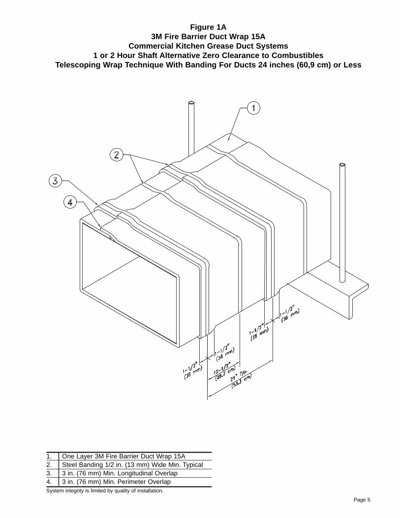
Figure 1A3M Fire Barrier Duct Wrap 15A
Commercial Kitchen Grease Duct Systems 1 or 2 Hour Shaft Alternative Zero Clearance to Combustibles
Telescoping Wrap Technique With Banding For Ducts 24 inches (60,9 cm) or Less
1. One Layer 3M Fire Barrier Duct Wrap 15A2. Steel Banding 1/2 in. (13 mm) Wide Min. Typical3. 3 in. (76 mm) Min. Longitudinal Overlap4. 3 in. (76 mm) Min. Perimeter OverlapSystem integrity is limited by quality of installation.
Page 5
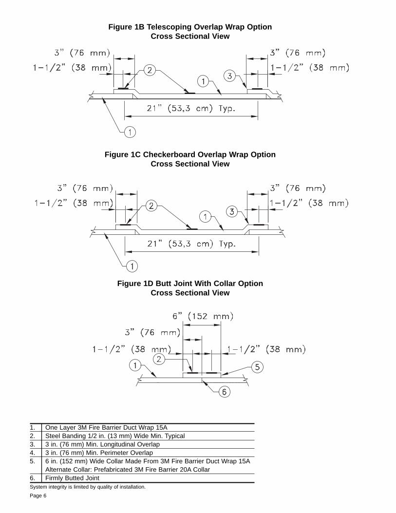
Figure 1B Telescoping Overlap Wrap OptionCross Sectional View
1. One Layer 3M Fire Barrier Duct Wrap 15A2. Steel Banding 1/2 in. (13 mm) Wide Min. Typical3. 3 in. (76 mm) Min. Longitudinal Overlap4. 3 in. (76 mm) Min. Perimeter Overlap5. 6 in. (152 mm) Wide Collar Made From 3M Fire Barrier Duct Wrap 15A
Alternate Collar: Prefabricated 3M Fire Barrier 20A Collar6. Firmly Butted JointSystem integrity is limited by quality of installation.
Figure 1C Checkerboard Overlap Wrap OptionCross Sectional View
Figure 1D Butt Joint With Collar OptionCross Sectional View
Page 6
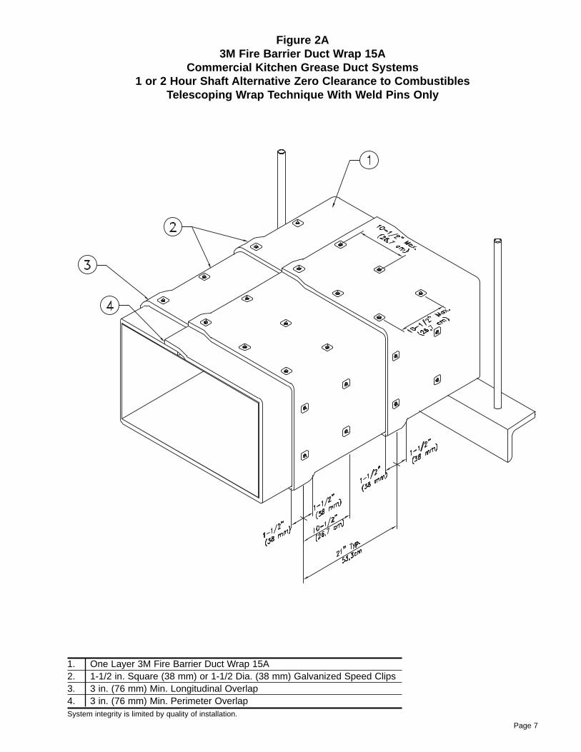
Figure 2A3M Fire Barrier Duct Wrap 15A
Commercial Kitchen Grease Duct Systems 1 or 2 Hour Shaft Alternative Zero Clearance to Combustibles
Telescoping Wrap Technique With Weld Pins Only
1. One Layer 3M Fire Barrier Duct Wrap 15A2. 1-1/2 in. Square (38 mm) or 1-1/2 Dia. (38 mm) Galvanized Speed Clips3. 3 in. (76 mm) Min. Longitudinal Overlap4. 3 in. (76 mm) Min. Perimeter OverlapSystem integrity is limited by quality of installation.
Page 7
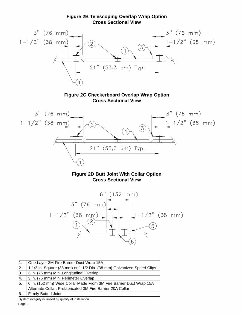
1. One Layer 3M Fire Barrier Duct Wrap 15A2. 1-1/2 in. Square (38 mm) or 1-1/2 Dia. (38 mm) Galvanized Speed Clips3. 3 in. (76 mm) Min. Longitudinal Overlap4. 3 in. (76 mm) Min. Perimeter Overlap5. 6 in. (152 mm) Wide Collar Made From 3M Fire Barrier Duct Wrap 15A
Alternate Collar: Prefabricated 3M Fire Barrier 20A Collar6. Firmly Butted JointSystem integrity is limited by quality of installation.
Figure 2B Telescoping Overlap Wrap OptionCross Sectional View
Figure 2C Checkerboard Overlap Wrap OptionCross Sectional View
Figure 2D Butt Joint With Collar OptionCross Sectional View
Page 8
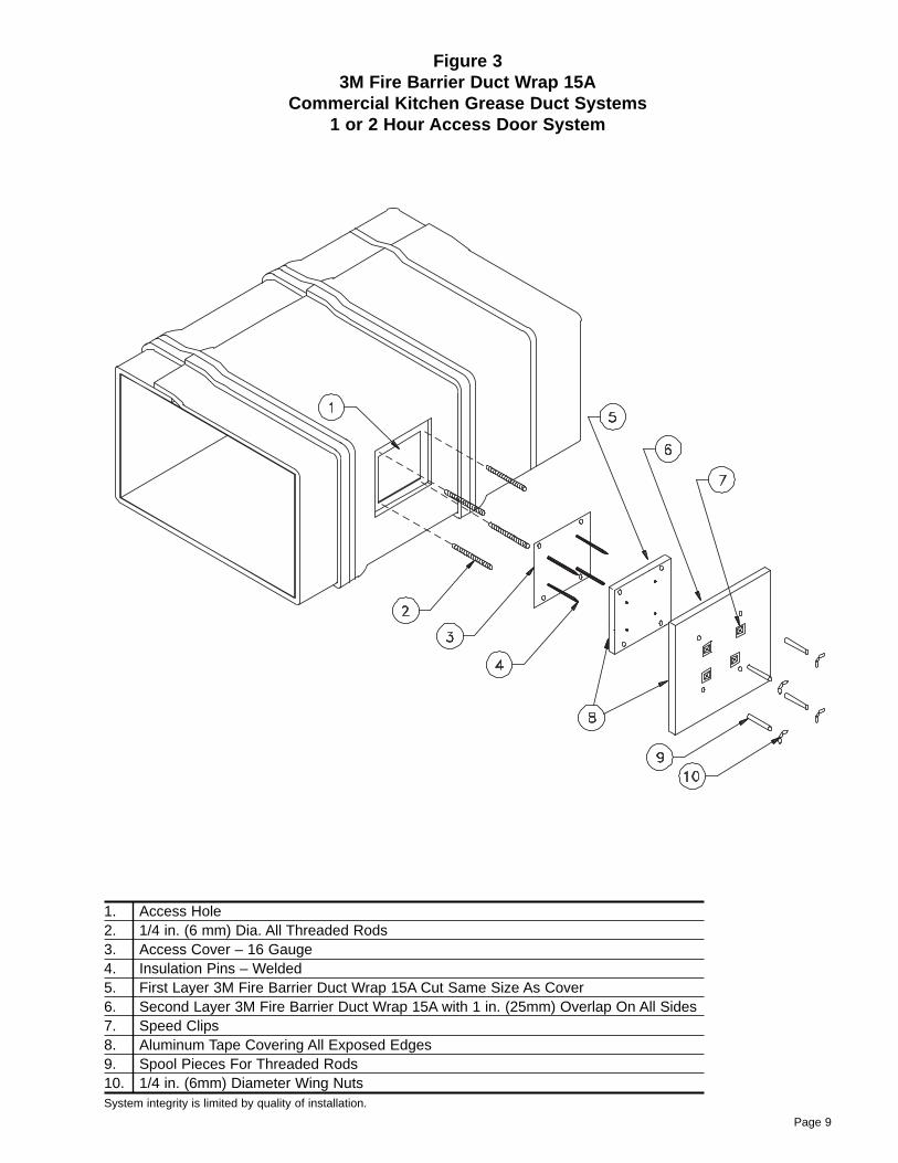
Figure 33M Fire Barrier Duct Wrap 15A
Commercial Kitchen Grease Duct Systems 1 or 2 Hour Access Door System
1. Access Hole2. 1/4 in. (6 mm) Dia. All Threaded Rods3. Access Cover – 16 Gauge4. Insulation Pins – Welded5. First Layer 3M Fire Barrier Duct Wrap 15A Cut Same Size As Cover6. Second Layer 3M Fire Barrier Duct Wrap 15A with 1 in. (25mm) Overlap On All Sides7. Speed Clips8. Aluminum Tape Covering All Exposed Edges9. Spool Pieces For Threaded Rods10. 1/4 in. (6mm) Diameter Wing NutsSystem integrity is limited by quality of installation.
Page 9
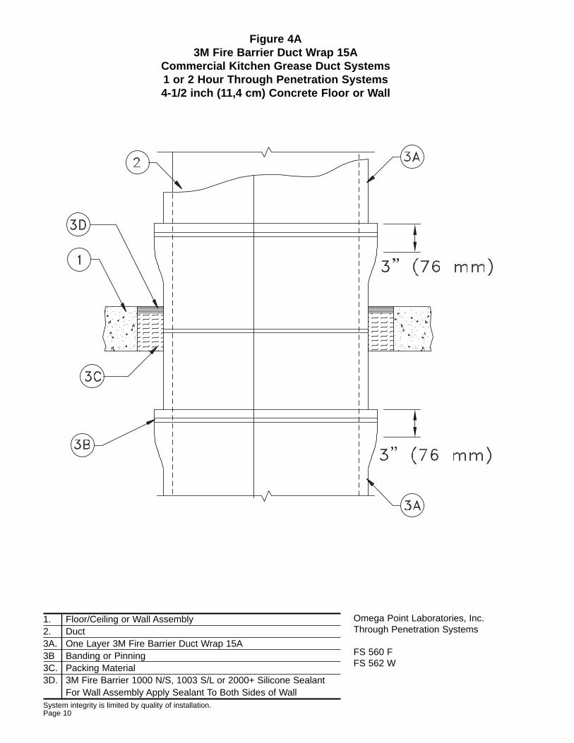
Figure 4A3M Fire Barrier Duct Wrap 15A
Commercial Kitchen Grease Duct Systems 1 or 2 Hour Through Penetration Systems4-1/2 inch (11,4 cm) Concrete Floor or Wall
1. Floor/Ceiling or Wall Assembly2. Duct3A. One Layer 3M Fire Barrier Duct Wrap 15A3B Banding or Pinning3C. Packing Material3D. 3M Fire Barrier 1000 N/S, 1003 S/L or 2000+ Silicone Sealant
For Wall Assembly Apply Sealant To Both Sides of WallSystem integrity is limited by quality of installation.Page 10
Omega Point Laboratories, Inc.Through Penetration Systems
FS 560 FFS 562 W
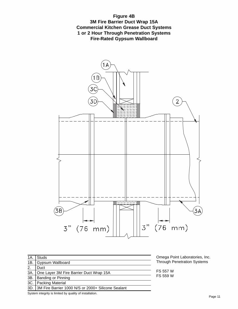
Figure 4B3M Fire Barrier Duct Wrap 15A
Commercial Kitchen Grease Duct Systems 1 or 2 Hour Through Penetration Systems
Fire-Rated Gypsum Wallboard
1A. Studs1B. Gypsum Wallboard2. Duct3A. One Layer 3M Fire Barrier Duct Wrap 15A3B. Banding or Pinning3C. Packing Material3D. 3M Fire Barrier 1000 N/S or 2000+ Silicone SealantSystem integrity is limited by quality of installation.
Page 11
Omega Point Laboratories, Inc.Through Penetration Systems
FS 557 WFS 559 W
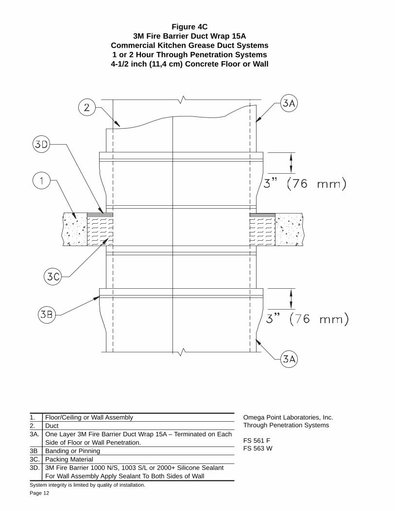
Figure 4C3M Fire Barrier Duct Wrap 15A
Commercial Kitchen Grease Duct Systems 1 or 2 Hour Through Penetration Systems4-1/2 inch (11,4 cm) Concrete Floor or Wall
1. Floor/Ceiling or Wall Assembly2. Duct3A. One Layer 3M Fire Barrier Duct Wrap 15A – Terminated on Each
Side of Floor or Wall Penetration.3B Banding or Pinning3C. Packing Material3D. 3M Fire Barrier 1000 N/S, 1003 S/L or 2000+ Silicone Sealant
For Wall Assembly Apply Sealant To Both Sides of WallSystem integrity is limited by quality of installation.
Page 12
Omega Point Laboratories, Inc.Through Penetration Systems
FS 561 FFS 563 W
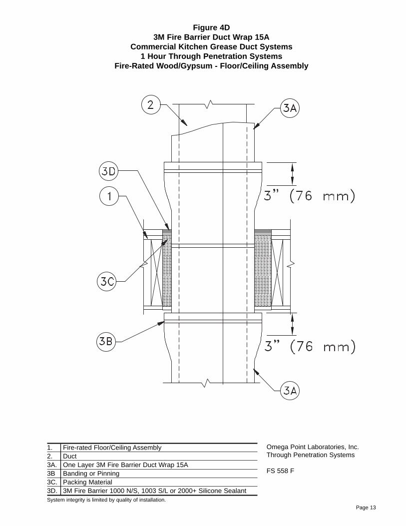
Figure 4D3M Fire Barrier Duct Wrap 15A
Commercial Kitchen Grease Duct Systems 1 Hour Through Penetration Systems
Fire-Rated Wood/Gypsum - Floor/Ceiling Assembly
1. Fire-rated Floor/Ceiling Assembly2. Duct3A. One Layer 3M Fire Barrier Duct Wrap 15A3B Banding or Pinning3C. Packing Material3D. 3M Fire Barrier 1000 N/S, 1003 S/L or 2000+ Silicone SealantSystem integrity is limited by quality of installation.
Page 13
Omega Point Laboratories, Inc.Through Penetration Systems
FS 558 F
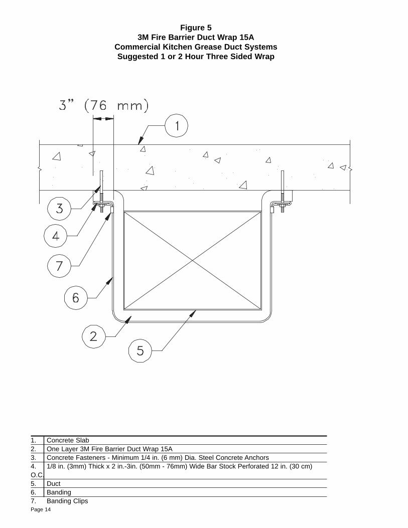
Figure 53M Fire Barrier Duct Wrap 15A
Commercial Kitchen Grease Duct Systems Suggested 1 or 2 Hour Three Sided Wrap
1. Concrete Slab2. One Layer 3M Fire Barrier Duct Wrap 15A3. Concrete Fasteners - Minimum 1/4 in. (6 mm) Dia. Steel Concrete Anchors4. 1/8 in. (3mm) Thick x 2 in.-3in. (50mm - 76mm) Wide Bar Stock Perforated 12 in. (30 cm)O.C.5. Duct6. Banding7. Banding ClipsPage 14
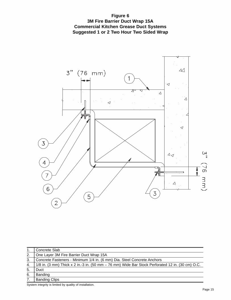
Figure 63M Fire Barrier Duct Wrap 15A
Commercial Kitchen Grease Duct Systems Suggested 1 or 2 Two Hour Two Sided Wrap
1. Concrete Slab2. One Layer 3M Fire Barrier Duct Wrap 15A3. Concrete Fasteners - Minimum 1/4 in. (6 mm) Dia. Steel Concrete Anchors4. 1/8 in. (3 mm) Thick x 2 in.-3 in. (50 mm – 76 mm) Wide Bar Stock Perforated 12 in. (30 cm) O.C.5. Duct6. Banding7. Banding ClipsSystem integrity is limited by quality of installation.
Page 15
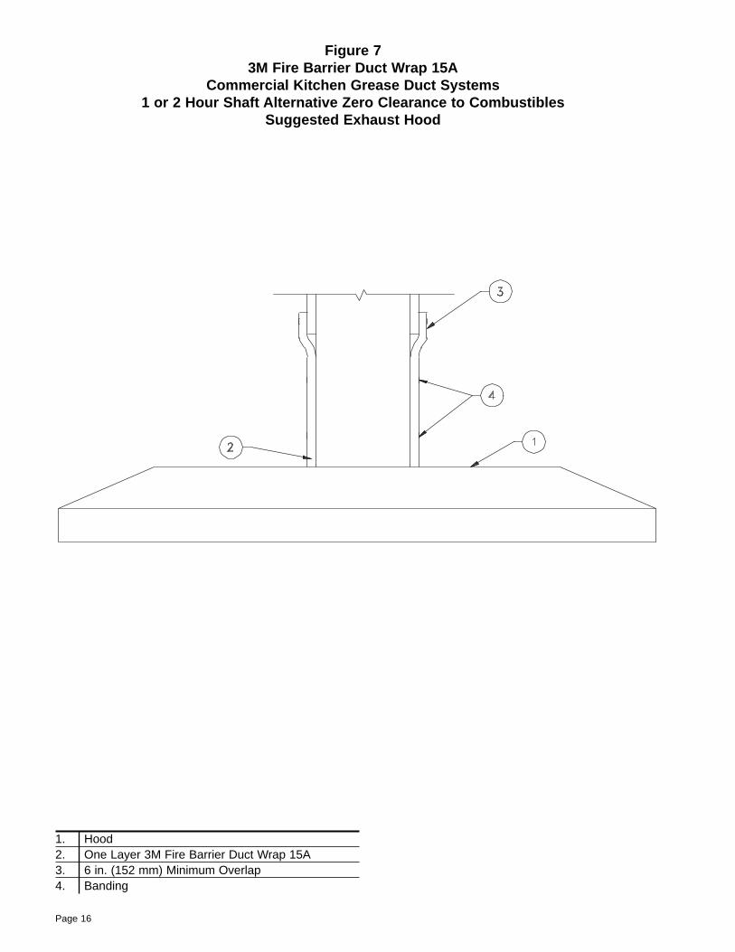
Figure 73M Fire Barrier Duct Wrap 15A
Commercial Kitchen Grease Duct Systems 1 or 2 Hour Shaft Alternative Zero Clearance to Combustibles
Suggested Exhaust Hood
1. Hood2. One Layer 3M Fire Barrier Duct Wrap 15A3. 6 in. (152 mm) Minimum Overlap4. Banding
Page 16
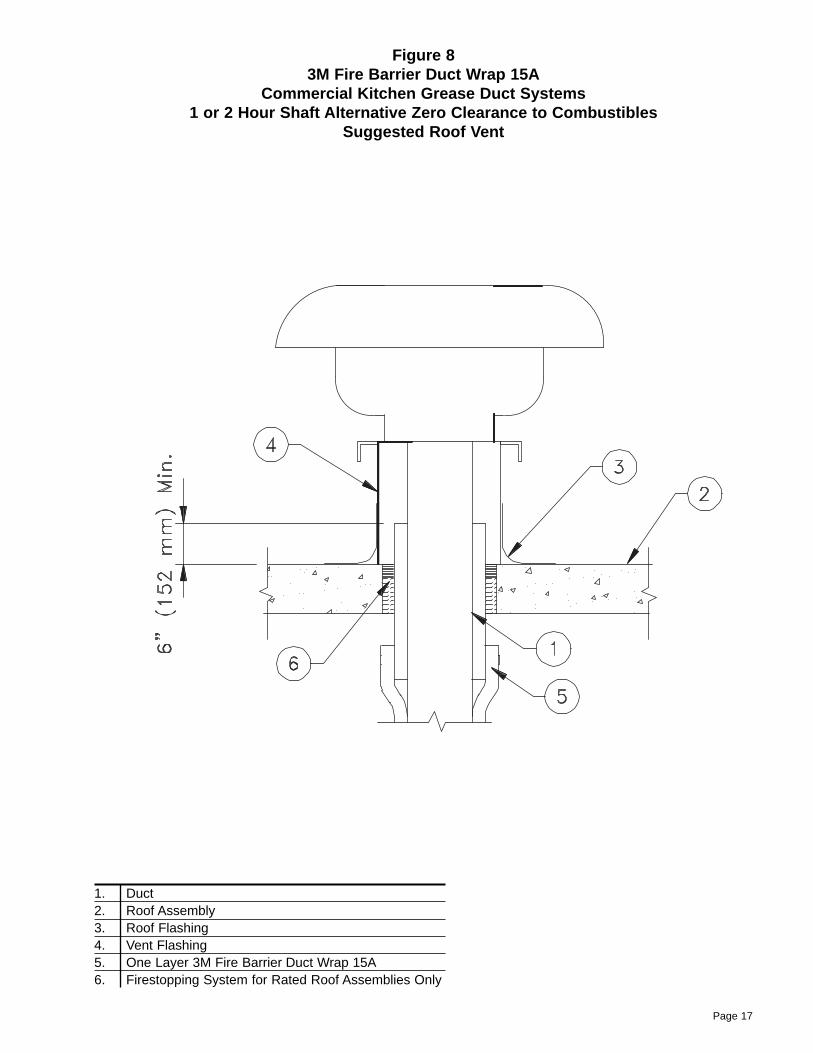
Figure 83M Fire Barrier Duct Wrap 15A
Commercial Kitchen Grease Duct Systems 1 or 2 Hour Shaft Alternative Zero Clearance to Combustibles
Suggested Roof Vent
1. Duct2. Roof Assembly3. Roof Flashing4. Vent Flashing5. One Layer 3M Fire Barrier Duct Wrap 15A6. Firestopping System for Rated Roof Assemblies Only
Page 17
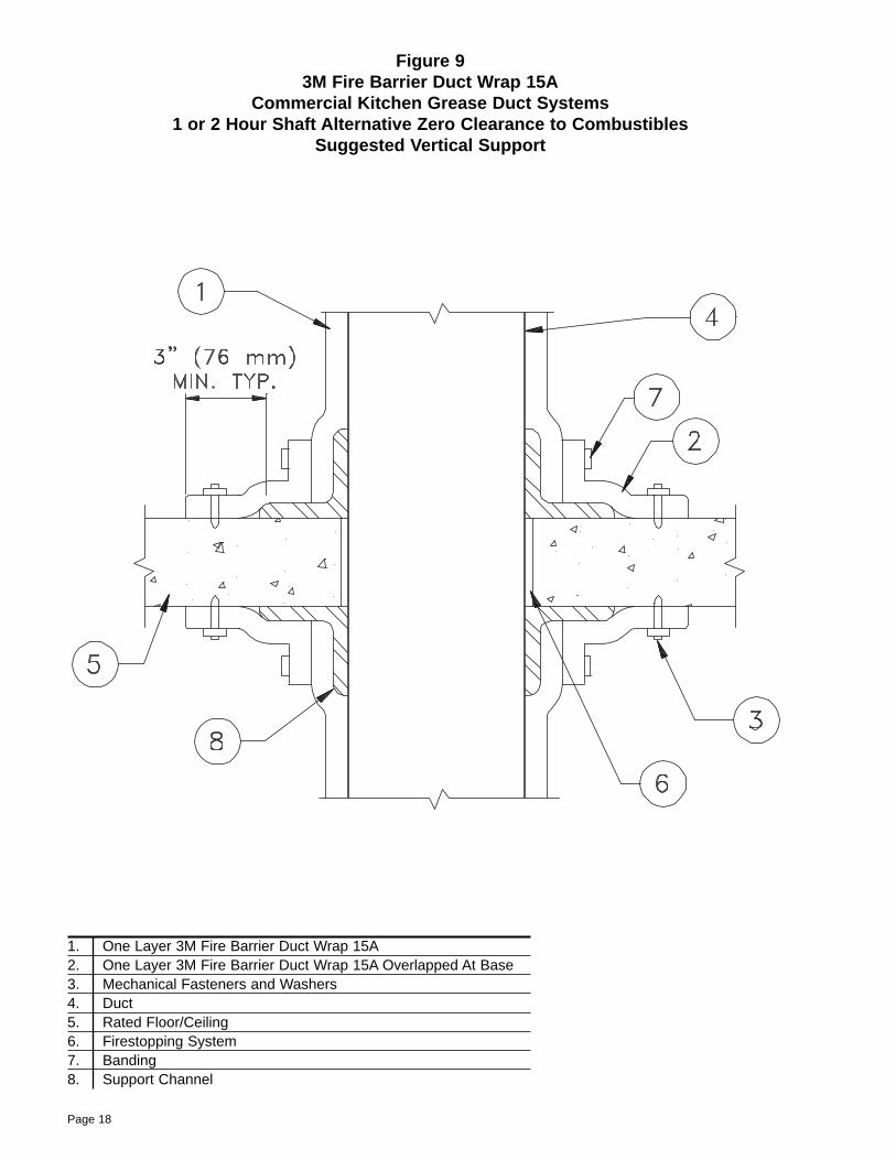
1. One Layer 3M Fire Barrier Duct Wrap 15A2. One Layer 3M Fire Barrier Duct Wrap 15A Overlapped At Base3. Mechanical Fasteners and Washers4. Duct5. Rated Floor/Ceiling6. Firestopping System7. Banding8. Support Channel
Figure 93M Fire Barrier Duct Wrap 15A
Commercial Kitchen Grease Duct Systems 1 or 2 Hour Shaft Alternative Zero Clearance to Combustibles
Suggested Vertical Support
Page 18

Page 19
Printed in U.S.A.
© 3M 2001 98-0400-5054-8 (July 2001)
Specified Construction Products Department
3M Center 223-2N-21St. Paul, MN 55144-1000(800) 328-1687
3
Warranty and Limited Remedy. This product will be free from defects in material and manufacture for a peri-od of ninety (90) days from date of purchase. 3M MAKES NO OTHER WARRANTIES INCLUDING, BUT NOTLIMITED TO, ANY IMPLIED WARRANTY OR MERCHANTIBILITY OR FITNESS FOR A PARTICULAR PURPOSE. User is responsible for determining whether the 3M product is fit for a particular purpose and suitable for user’s method of application. If this 3M product is proved to be defective within the warranty periodstated above, your exclusive remedy and 3M’s sole obligation shall be, at 3M’s option, to replace or repair the3M product or refund the purchase price of the product.
Limitation of Liability. Except where prohibited by law, 3M will not be liable for any loss or damagesarising from the use of this 3M product, whether direct, indirect, special, incidental or consequential,regardless of the legal theory asserted, including warranty, contract, negligence or strict liability.