Embed Size (px)
Citation preview
High Integrity, Double Block and Bleed Plug Valve
DURASEAL™
www.franklinvalve.com
An improved valve with a proven historyWe took an alternative path. Unlike many valve manufacturers who often strip valves in their quest to reduce manufacturing costs, we have taken a proven double block and bleed plug valve and improved its design.
With the new DuraSeal™, you get the proven advantages of a valve that has been considered the standard of quality since 1951. To improve the valve’s integrity, we have incorporated a superior slip design and more durable body. To improve performance and longevity, we have incorporated a more reliable stem seal design.
In short, the new Franklin DuraSeal™ is made to last - not to make a quick sale.
Reliable double protection mechanical sealThe Franklin DuraSeal™ plug valve seals mechanically. During rotation of the plug there is no abrasion or wear between the sealing surfaces. When the slips reach the closed position they expand firmly into the valve body creating a primary elastomeric and secondary metal-to-metal backup seal. The DuraSeal™ does not require sealant under any circumstance to seal.
Fast Low Torque OperationThe DuraSeal™ can be easily automated using hydraulic or pneumatic or electric actuators. Torque requirements are low. In smaller sizes only two and one quarter turns can fully open or close the valve.
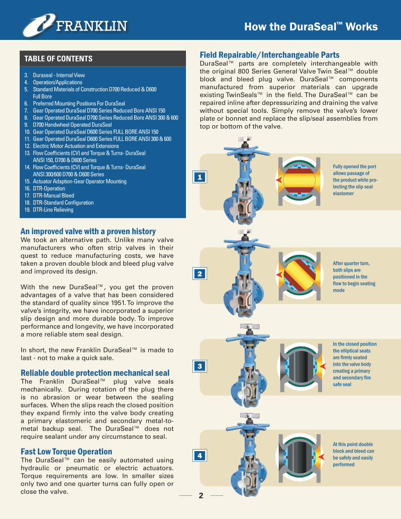
Field Repairable/Interchangeable PartsDuraSeal™ parts are completely interchangeable with the original 800 Series General Valve Twin Seal™ double block and bleed plug valve. DuraSeal™ components manufactured from superior materials can upgrade existing TwinSeals™ in the field. The DuraSeal™ can be repaired inline after depressurizing and draining the valve without special tools. Simply remove the valve’s lower plate or bonnet and replace the slip/seal assemblies from top or bottom of the valve.
1Fully opened the port allows passage of the product while pro-tecting the slip seal elastomer
2After quarter turn, both slips are positioned in the flow to begin seating mode
3
In the closed position the elliptical seats are firmly seated into the valve body creating a primary and secondary fire safe seal
4
At this point double block and bleed can be safely and easily performed
How the DuraSeal™ Works
2
3. Duraseal - Internal View4. Operation/Applications5. Standard Materials of Construction D700 Reduced & D600 Full Bore6. Preferred Mounting Positions For DuraSeal 7. Gear Operated DuraSeal D700 Series Reduced Bore ANSI 1508. Gear Operated DuraSeal D700 Series Reduced Bore ANSI 300 & 6009. D700 Handwheel Operated DuraSeal10. Gear Operated DuraSeal D600 Series FULL BORE ANSI 15011. Gear Operated DuraSeal D600 Series FULL BORE ANSI 300 & 60012. Electric Motor Actuation and Extensions13. Flow Coefficients (CV) and Torque & Turns- DuraSeal ANSI 150, D700 & D600 Series14. Flow Coefficients (CV) and Torque & Turns- DuraSeal ANSI 300/600 D700 & D600 Series15. Actuator Adaption-Gear Operator Mounting 16. DTR-Operation17. DTR-Manual Bleed18. DTR-Standard Configuration 19. DTR-Line Relieving
TABLE OF CONTENTS
The Franklin DuraSeal™ High Integrity Double Block and Bleed Valve
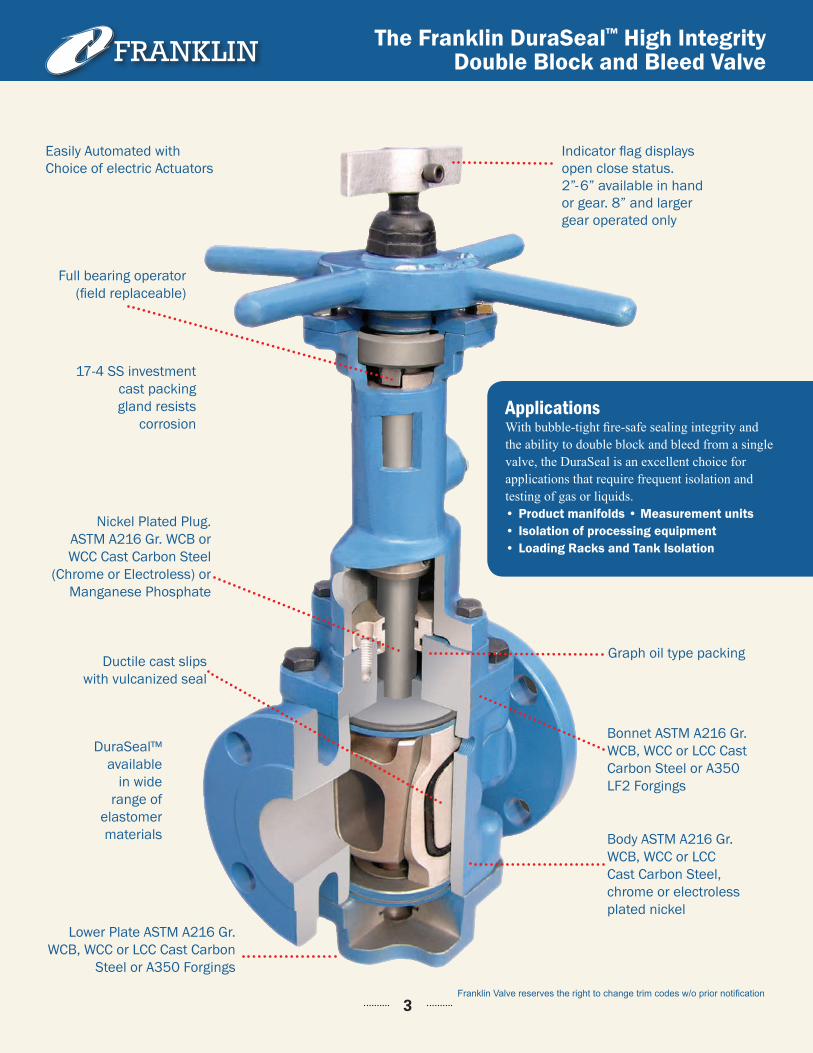
Full bearing operator(field replaceable)
17-4 SS investment cast packinggland resists
corrosion
Nickel Plated Plug.ASTM A216 Gr. WCB or WCC Cast Carbon Steel
(Chrome or Electroless) or Manganese Phosphate
Ductile cast slips with vulcanized seal
Lower Plate ASTM A216 Gr. WCB, WCC or LCC Cast Carbon
Steel or A350 Forgings
DuraSeal™ available
in wide range of
elastomer materials
Indicator flag displays open close status. 2”-6” available in hand or gear. 8” and larger gear operated only
Easily Automated with Choice of electric Actuators
Graph oil type packing
Bonnet ASTM A216 Gr. WCB, WCC or LCC Cast Carbon Steel or A350 LF2 Forgings
Body ASTM A216 Gr. WCB, WCC or LCCCast Carbon Steel, chrome or electroless plated nickel
Franklin Valve reserves the right to change trim codes w/o prior notification3
ApplicationsWith bubble-tight fire-safe sealing integrity and the ability to double block and bleed from a single valve, the DuraSeal is an excellent choice for applications that require frequent isolation and testing of gas or liquids. • Product manifolds • Measurement units• Isolation of processing equipment• Loading Racks and Tank Isolation
Operation / Applications
VALVE OPERATION Opening the Valve: Turn the hand-wheel counter clockwise. During this operation the plug is raised while the slips are retracted away from the body. When the slips are fully retracted from the body seating area, the plug is then able to rotate 90 degrees to the fully open position. When the valve is in the full open position, the slips and slip seals are completely protected from line flow.
Closing the Valve: Turn the hand-wheel clockwise. During this operation the retracted plug and slips are rotated 90 degrees without body contact. This rotation continues until the slips are positioned over the up-stream and downstream port areas. Continued rotation of hand-wheel mechanically forces the plug down-ward and forces the slips outward to seal firmly against the valve body. This produces a secondary metal to metal seal on both upstream and downstream areas providing double isolation.
APPLICATION NOTES• Biofuels Product Isolation: Secure sealing of Biofuels is critical in protecting the environment. The
Duraseal® DBB with its verifiable secure shutoff is perfect when process must be contained.
• Multi-Product Manifolds: Some pipeline manifolds need to flow various products (e.g. diesel, jet fuel, gasoline, etc.) reliably and without contaminating one another. This DURASEAL® DBB Valve is used to provide positive shut off and zero leakage to prevent cross contamination.
• Prover Loops: In prover loops, the calibration of flow meters requires that every valve in the system must have zero leak rates. Any leak could mean an error in calibration. The DURASEAL® DBB Valve is used to ensure that when the valves in the system are closed, they are leak tight.
• Custody Transfer Units: Transfer of valuable media relies on accurate measurement of product. The DURASEAL® DBB provides secure tight shutoff ensuring that the transfer is accurate.
• Terminals: Loading and unloading tanker vessels requires positive sealing in order to prevent spillage into the water. The DURASEAL® DBB provides such positive sealing and is the most reliable in the market.
• Tank Farms (Oil Depots): Valves used for tank isolation needs to work reliably with zero leak rate. These valves are also operated frequently. The DURASEAL® DBB valves provide a reliable long term high integrity seal designed for frequent use with verifiable zero leak.
• Aviation Fueling Systems: Fuel hydrants at airports need to allow for quick maintenance, repair, leak locating and testing. This requires a valve that can close quickly and positively seal off the relevant sections. The DURASEAL® DBB Valve’s variable zero leak rate ensures that maintenance, repair, leak locating and hydrant testing can be done quickly and safely. Import/Export Facilities.
• Offshore Platforms: Secure shutoff is imperative on an offshore platform in that leakage can result in contamination of the water and possible equipment damage. The DURASEAL® DBB is the best choice for low pressure positive shutoff.
• Blending Units: The accurate blending of high grade fuels requires valves of high sealing integrity to insure accurate addition of additives in blending operations.
4
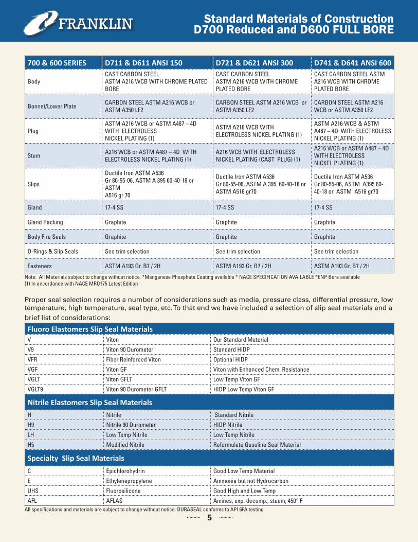
Standard Materials of Construction D700 Reduced and D600 FULL BORE
5
700 & 600 SERIES D711 & D611 ANSI 150 D721 & D621 ANSI 300 D741 & D641 ANSI 600
Body CAST CARBON STEELASTM A216 WCB WITH CHROME PLATED BORE
CAST CARBON STEELASTM A216 WCB WITH CHROME PLATED BORE
CAST CARBON STEEL ASTM A216 WCB WITH CHROME PLATED BORE
Bonnet/Lower Plate CARBON STEEL ASTM A216 WCB or ASTM A350 LF2
CARBON STEEL ASTM A216 WCB or ASTM A350 LF2
CARBON STEEL ASTM A216 WCB or ASTM A350 LF2
PlugASTM A216 WCB or ASTM A487 – 4D WITH ELECTROLESSNICKEL PLATING (1)
ASTM A216 WCB WITH ELECTROLESS NICKEL PLATING (1)
ASTM A216 WCB & ASTM A487 – 4D WITH ELECTROLESS NICKEL PLATING (1)
Stem A216 WCB or ASTM A487 – 4D WITH ELECTROLESS NICKEL PLATING (1)
A216 WCB WITH ELECTROLESS NICKEL PLATING (CAST PLUG) (1)
A216 WCB or ASTM A487 – 4D WITH ELECTROLESSNICKEL PLATING (1)
Slips
Ductile Iron ASTM A536Gr 80-55-06, ASTM A 395 60-40-18 or ASTMA516 gr 70
Ductile Iron ASTM A536Gr 80-55-06, ASTM A 395 60-40-18 orASTM A516 gr70
Ductile Iron ASTM A536Gr 80-55-06, ASTM A395 60-40-18 or ASTM A516 gr70
Gland 17-4 SS 17-4 SS 17-4 SS
Gland Packing Graphite Graphite Graphite
Body Fire Seals Graphite Graphite Graphite
O-Rings & Slip Seals See trim selection See trim selection See trim selection
Fasteners ASTM A193 Gr. B7 / 2H ASTM A193 Gr. B7 / 2H ASTM A193 Gr. B7 / 2H
Note: All Materials subject to change without notice. *Manganese Phosphate Coating available * NACE SPECIFICATION AVAILABLE *ENP Bore available(1) In accordance with NACE MRO175 Latest Edition
Proper seal selection requires a number of considerations such as media, pressure class, differential pressure, low temperature, high temperature, seal type, etc. To that end we have included a selection of slip seal materials and a brief list of considerations:
Fluoro Elastomers Slip Seal MaterialsV Viton Our Standard Material
V9 Viton 90 Durometer Standard HIDP
VFR Fiber Reinforced Viton Optional HIDP
VGF Viton GF Viton with Enhanced Chem. Resistance
VGLT Viton GFLT Low Temp Viton GF
VGLT9 Viton 90 Durometer GFLT HIDP Low Temp Viton GF
Nitrile Elastomers Slip Seal MaterialsH Nitrile Standard Nitrile
H9 Nitrile 90 Durometer HIDP Nitrile
LH Low Temp Nitrile Low Temp Nitrile
H5 Modified Nitrile Reformulate Gasoline Seal Material
Specialty Slip Seal MaterialsC Epichlorohydrin Good Low Temp Material
E Ethylenepropylene Ammonia but not Hydrocarbon
UHS Fluorosilicone Good High and Low Temp
AFL AFLAS Amines, exp. decomp., steam, 450° FAll specifications and materials are subject to change without notice. DURASEAL conforms to API 6FA testing
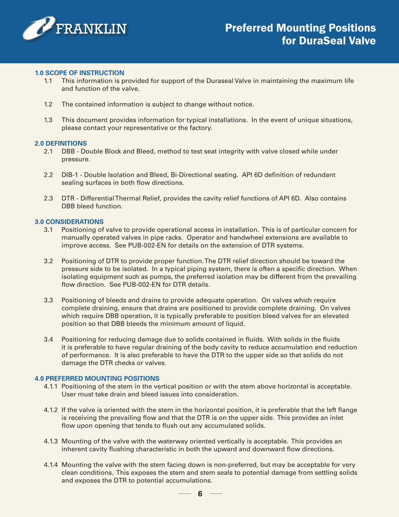
Preferred Mounting Positions for DuraSeal Valve
1.0 SCOPE OF INSTRUCTION 1.1 This information is provided for support of the Duraseal Valve in maintaining the maximum life and function of the valve.
1.2 The contained information is subject to change without notice.
1.3 This document provides information for typical installations. In the event of unique situations, please contact your representative or the factory.
2.0 DEFINITIONS 2.1 DBB - Double Block and Bleed, method to test seat integrity with valve closed while under pressure.
2.2 DIB-1 - Double Isolation and Bleed, Bi-Directional seating. API 6D definition of redundant sealing surfaces in both flow directions.
2.3 DTR - Differential Thermal Relief, provides the cavity relief functions of API 6D. Also contains DBB bleed function.
3.0 CONSIDERATIONS 3.1 Positioning of valve to provide operational access in installation. This is of particular concern for manually operated valves in pipe racks. Operator and handwheel extensions are available to improve access. See PUB-002-EN for details on the extension of DTR systems. 3.2 Positioning of DTR to provide proper function. The DTR relief direction should be toward the pressure side to be isolated. In a typical piping system, there is often a specific direction. When isolating equipment such as pumps, the preferred isolation may be different from the prevailing flow direction. See PUB-002-EN for DTR details.
3.3 Positioning of bleeds and drains to provide adequate operation. On valves which require complete draining, ensure that drains are positioned to provide complete draining. On valves which require DBB operation, it is typically preferable to position bleed valves for an elevated position so that DBB bleeds the minimum amount of liquid.
3.4 Positioning for reducing damage due to solids contained in fluids. With solids in the fluids it is preferable to have regular draining of the body cavity to reduce accumulation and reduction of performance. It is also preferable to have the DTR to the upper side so that solids do not damage the DTR checks or valves.
4.0 PREFERRED MOUNTING POSITIONS 4.1.1 Positioning of the stem in the vertical position or with the stem above horizontal is acceptable. User must take drain and bleed issues into consideration.
4.1.2 If the valve is oriented with the stem in the horizontal position, it is preferable that the left flange is receiving the prevailing flow and that the DTR is on the upper side. This provides an inlet flow upon opening that tends to flush out any accumulated solids. 4.1.3 Mounting of the valve with the waterway oriented vertically is acceptable. This provides an inherent cavity flushing characteristic in both the upward and downward flow directions.
4.1.4 Mounting the valve with the stem facing down is non-preferred, but may be acceptable for very clean conditions. This exposes the stem and stem seals to potential damage from settling solids and exposes the DTR to potential accumulations.
6
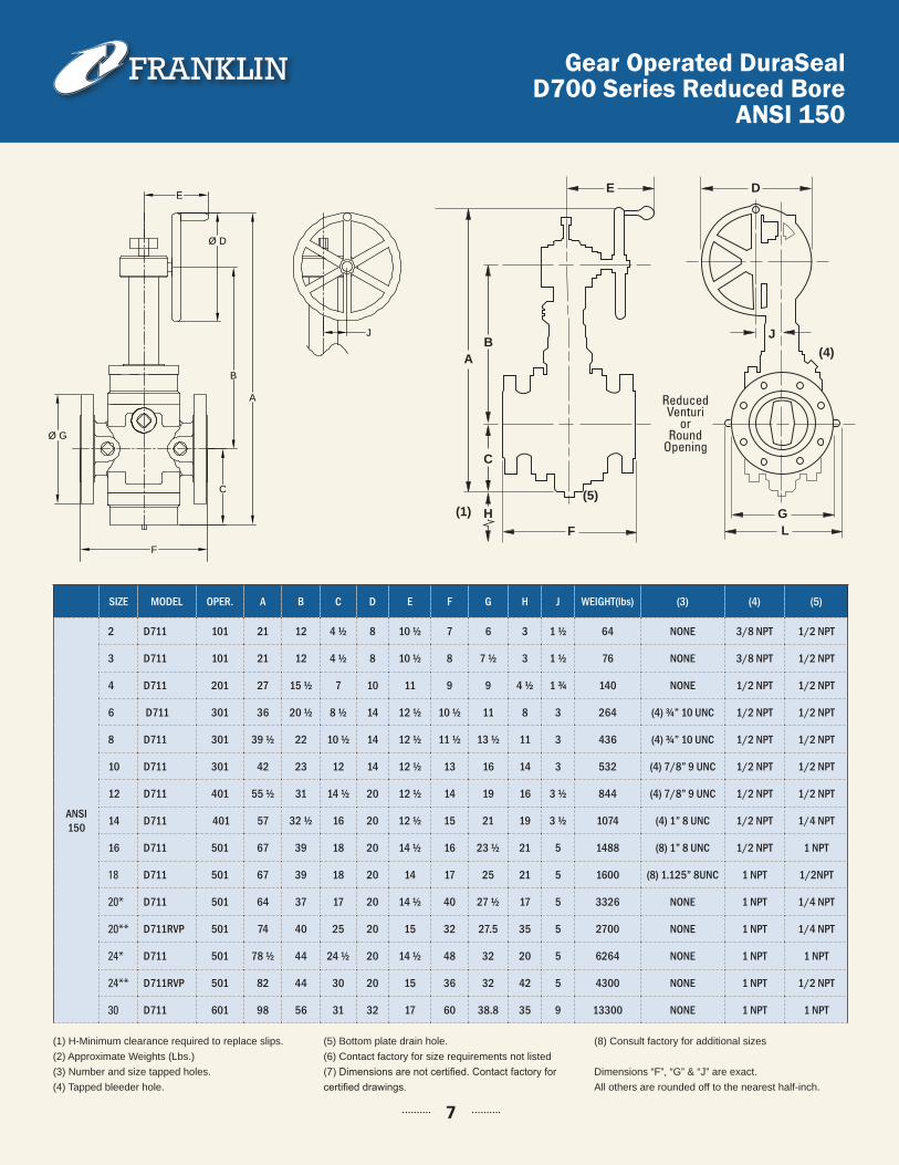
SIZE MODEL OPER. A B C D E F G H J WEIGHT(lbs) (3) (4) (5)
ANSI 150
2 D711 101 21 12 4 ½ 8 10 ½ 7 6 3 1 ½ 64 NONE 3/8 NPT 1/2 NPT
3 D711 101 21 12 4 ½ 8 10 ½ 8 7 ½ 3 1 ½ 76 NONE 3/8 NPT 1/2 NPT
4 D711 201 27 15 ½ 7 10 11 9 9 4 ½ 1 ¾ 140 NONE 1/2 NPT 1/2 NPT
6 D711 301 36 20 ½ 8 ½ 14 12 ½ 10 ½ 11 8 3 264 (4) ¾” 10 UNC 1/2 NPT 1/2 NPT
8 D711 301 39 ½ 22 10 ½ 14 12 ½ 11 ½ 13 ½ 11 3 436 (4) ¾” 10 UNC 1/2 NPT 1/2 NPT
10 D711 301 42 23 12 14 12 ½ 13 16 14 3 532 (4) 7/8” 9 UNC 1/2 NPT 1/2 NPT
12 D711 401 55 ½ 31 14 ½ 20 12 ½ 14 19 16 3 ½ 844 (4) 7/8” 9 UNC 1/2 NPT 1/2 NPT
14 D711 401 57 32 ½ 16 20 12 ½ 15 21 19 3 ½ 1074 (4) 1” 8 UNC 1/2 NPT 1/4 NPT
16 D711 501 67 39 18 20 14 ½ 16 23 ½ 21 5 1488 (8) 1” 8 UNC 1/2 NPT 1 NPT
18 D711 501 67 39 18 20 14 17 25 21 5 1600 (8) 1.125” 8UNC 1 NPT 1/2NPT
20* D711 501 64 37 17 20 14 ½ 40 27 ½ 17 5 3326 NONE 1 NPT 1/4 NPT
20** D711RVP 501 74 40 25 20 15 32 27.5 35 5 2700 NONE 1 NPT 1/4 NPT
24* D711 501 78 ½ 44 24 ½ 20 14 ½ 48 32 20 5 6264 NONE 1 NPT 1 NPT
24** D711RVP 501 82 44 30 20 15 36 32 42 5 4300 NONE 1 NPT 1/2 NPT
30 D711 601 98 56 31 32 17 60 38.8 35 9 13300 NONE 1 NPT 1 NPT
Gear Operated DuraSealD700 Series Reduced Bore
ANSI 150
7
B
A
D
H
C
FG
(4)
(1)(5)
DE
J
G
C
F L
BA
H(1)(5)
(4)
TYPICAL HAND OPERATED VALVE TYPICAL GEAR OPERATED VALVE
Reduced Venturi
or Round
Opening
(1) H-Minimum clearance required to replace slips.(2) Approximate Weights (Lbs.)(3) Number and size tapped holes.(4) Tapped bleeder hole.
(5) Bottom plate drain hole.(6) Contact factory for size requirements not listed(7) Dimensions are not certified. Contact factory for certified drawings.
(8) Consult factory for additional sizes
Dimensions “F”, “G” & “J” are exact. All others are rounded off to the nearest half-inch.
F
Ø D
B
A
C
Ø G
E
J
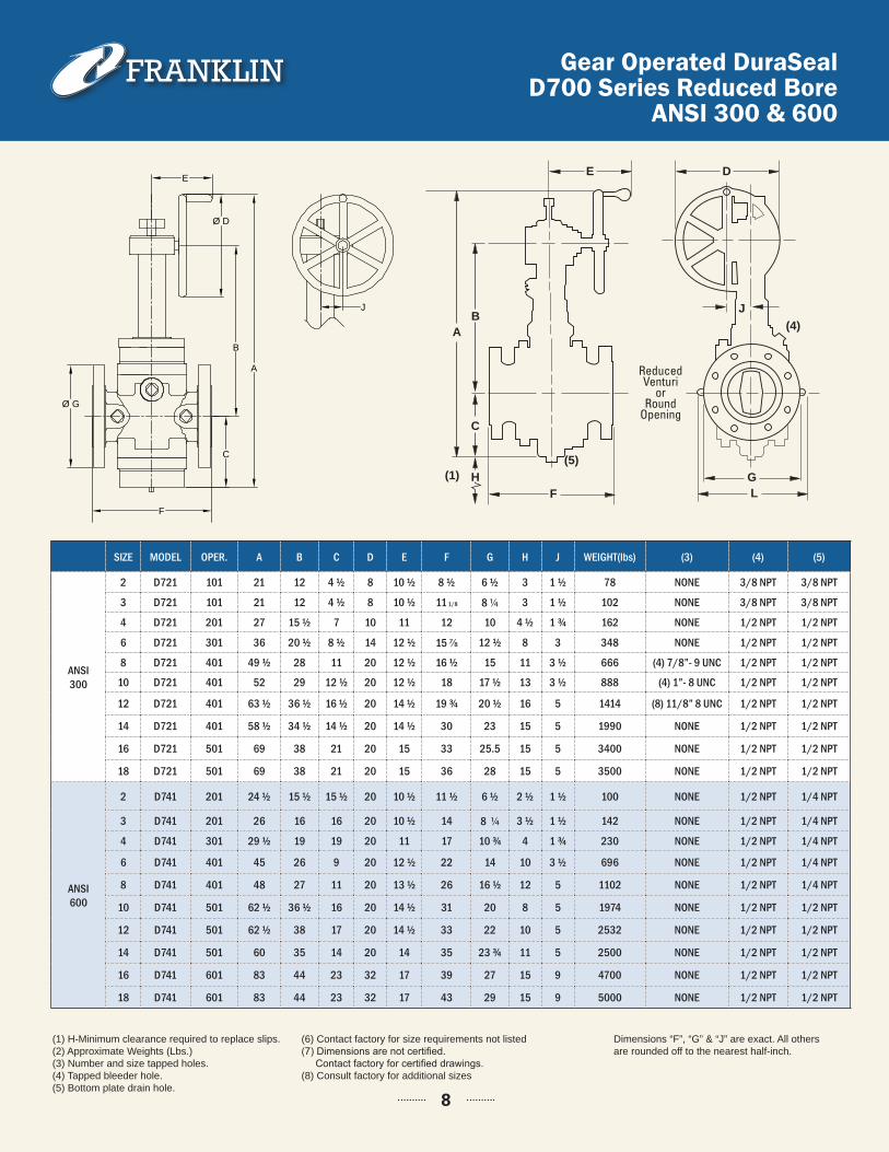
SIZE MODEL OPER. A B C D E F G H J WEIGHT(lbs) (3) (4) (5)
Dimensions “F”, “G” & “J” are exact. All others are rounded off to the nearest half-inch.
(1) H-Minimum clearance required to replace slips.(2) Approximate Weights (Lbs.)(3) Number and size tapped holes.(4) Tapped bleeder hole.(5) Bottom plate drain hole.
(6) Contact factory for size requirements not listed(7) Dimensions are not certified. Contact factory for certified drawings.(8) Consult factory for additional sizes
Gear Operated DuraSealD700 Series Reduced Bore
ANSI 300 & 600
ANSI300
2 D721 101 21 12 4 ½ 8 10 ½ 8 ½ 6 ½ 3 1 ½ 78 NONE 3/8 NPT 3/8 NPT
3 D721 101 21 12 4 ½ 8 10 ½ 11 1/8 8 1/4 3 1 ½ 102 NONE 3/8 NPT 3/8 NPT
4 D721 201 27 15 ½ 7 10 11 12 10 4 ½ 1 ¾ 162 NONE 1/2 NPT 1/2 NPT
6 D721 301 36 20 ½ 8 ½ 14 12 ½ 15 7/8 12 ½ 8 3 348 NONE 1/2 NPT 1/2 NPT
8 D721 401 49 ½ 28 11 20 12 ½ 16 ½ 15 11 3 ½ 666 (4) 7/8”- 9 UNC 1/2 NPT 1/2 NPT
10 D721 401 52 29 12 ½ 20 12 ½ 18 17 ½ 13 3 ½ 888 (4) 1”- 8 UNC 1/2 NPT 1/2 NPT
12 D721 401 63 ½ 36 ½ 16 ½ 20 14 ½ 19 ¾ 20 ½ 16 5 1414 (8) 11/8” 8 UNC 1/2 NPT 1/2 NPT
14 D721 401 58 ½ 34 ½ 14 ½ 20 14 ½ 30 23 15 5 1990 NONE 1/2 NPT 1/2 NPT
16 D721 501 69 38 21 20 15 33 25.5 15 5 3400 NONE 1/2 NPT 1/2 NPT
18 D721 501 69 38 21 20 15 36 28 15 5 3500 NONE 1/2 NPT 1/2 NPT
ANSI600
2 D741 201 24 ½ 15 ½ 15 ½ 20 10 ½ 11 ½ 6 ½ 2 ½ 1 ½ 100 NONE 1/2 NPT 1/4 NPT
3 D741 201 26 16 16 20 10 ½ 14 8 1/4 3 ½ 1 ½ 142 NONE 1/2 NPT 1/4 NPT
4 D741 301 29 ½ 19 19 20 11 17 10 ¾ 4 1 ¾ 230 NONE 1/2 NPT 1/4 NPT
6 D741 401 45 26 9 20 12 ½ 22 14 10 3 ½ 696 NONE 1/2 NPT 1/4 NPT
8 D741 401 48 27 11 20 13 ½ 26 16 ½ 12 5 1102 NONE 1/2 NPT 1/4 NPT
10 D741 501 62 ½ 36 ½ 16 20 14 ½ 31 20 8 5 1974 NONE 1/2 NPT 1/2 NPT
12 D741 501 62 ½ 38 17 20 14 ½ 33 22 10 5 2532 NONE 1/2 NPT 1/2 NPT
14 D741 501 60 35 14 20 14 35 23 ¾ 11 5 2500 NONE 1/2 NPT 1/2 NPT
16 D741 601 83 44 23 32 17 39 27 15 9 4700 NONE 1/2 NPT 1/2 NPT
18 D741 601 83 44 23 32 17 43 29 15 9 5000 NONE 1/2 NPT 1/2 NPT
8
B
A
D
H
C
FG
(4)
(1)(5)
DE
J
G
C
F L
BA
H(1)(5)
(4)
TYPICAL HAND OPERATED VALVE TYPICAL GEAR OPERATED VALVE
Reduced Venturi
or Round
Opening
F
Ø D
B
A
C
Ø G
E
J
B
A
D
H
C
FG
(4)
(1)(5)
DE
J
G
C
F L
BA
H(1)(5)
(4)
TYPICAL HAND OPERATED VALVE TYPICAL GEAR OPERATED VALVE
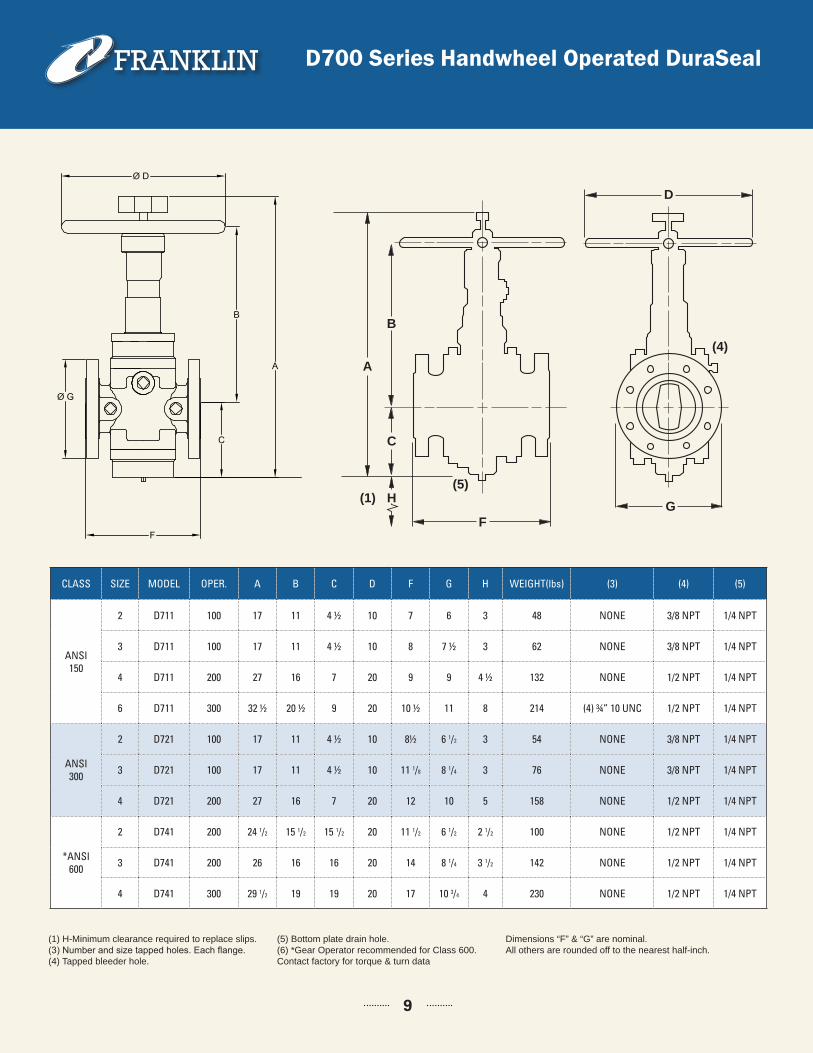
(1) H-Minimum clearance required to replace slips.(3) Number and size tapped holes. Each flange. (4) Tapped bleeder hole.
(5) Bottom plate drain hole.(6) *Gear Operator recommended for Class 600. Contact factory for torque & turn data
Dimensions “F” & “G” are nominal. All others are rounded off to the nearest half-inch.
D700 Series Handwheel Operated DuraSeal
CLASS SIZE MODEL OPER. A B C D F G H WEIGHT(lbs) (3) (4) (5)
ANSI150
2 D711 100 17 11 4 ½ 10 7 6 3 48 NONE 3/8 NPT 1/4 NPT
3 D711 100 17 11 4 ½ 10 8 7 ½ 3 62 NONE 3/8 NPT 1/4 NPT
4 D711 200 27 16 7 20 9 9 4 ½ 132 NONE 1/2 NPT 1/4 NPT
6 D711 300 32 ½ 20 ½ 9 20 10 ½ 11 8 214 (4) ¾” 10 UNC 1/2 NPT 1/4 NPT
ANSI300
2 D721 100 17 11 4 ½ 10 8½ 6 1/2 3 54 NONE 3/8 NPT 1/4 NPT
3 D721 100 17 11 4 ½ 10 11 1/8 8 1/4 3 76 NONE 3/8 NPT 1/4 NPT
4 D721 200 27 16 7 20 12 10 5 158 NONE 1/2 NPT 1/4 NPT
*ANSI600
2 D741 200 24 1/2 15 1/2 15 1/2 20 11 1/2 6 1/2 2 1/2 100 NONE 1/2 NPT 1/4 NPT
3 D741 200 26 16 16 20 14 8 1/4 3 1/2 142 NONE 1/2 NPT 1/4 NPT
4 D741 300 29 1/2 19 19 20 17 10 3/4 4 230 NONE 1/2 NPT 1/4 NPT
9
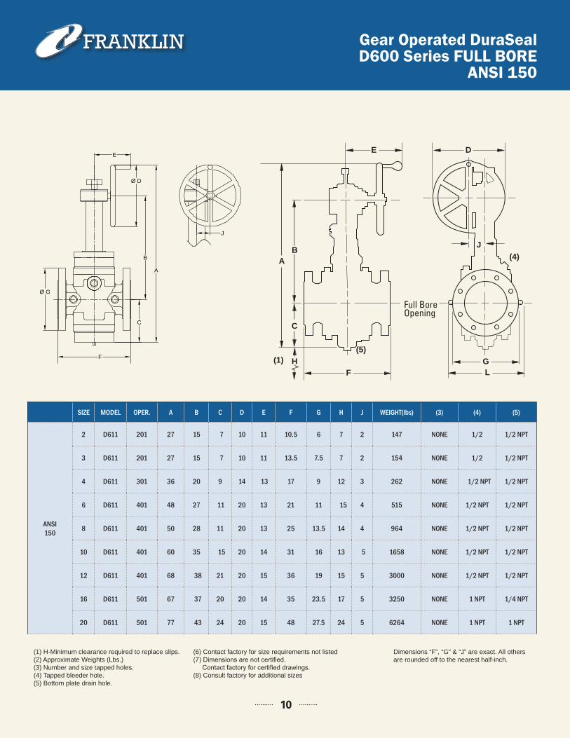
SIZE MODEL OPER. A B C D E F G H J WEIGHT(lbs) (3) (4) (5)
ANSI 150
2 D611 201 27 15 7 10 11 10.5 6 7 2 147 NONE 1/2 1/2 NPT
3 D611 201 27 15 7 10 11 13.5 7.5 7 2 154 NONE 1/2 1/2 NPT
4 D611 301 36 20 9 14 13 17 9 12 3 262 NONE 1/2 NPT 1/2 NPT
6 D611 401 48 27 11 20 13 21 11 15 4 515 NONE 1/2 NPT 1/2 NPT
8 D611 401 50 28 11 20 13 25 13.5 14 4 964 NONE 1/2 NPT 1/2 NPT
10 D611 401 60 35 15 20 14 31 16 13 5 1658 NONE 1/2 NPT 1/2 NPT
12 D611 401 68 38 21 20 15 36 19 15 5 3000 NONE 1/2 NPT 1/2 NPT
16 D611 501 67 37 20 20 14 35 23.5 17 5 3250 NONE 1 NPT 1/4 NPT
20 D611 501 77 43 24 20 15 48 27.5 24 5 6264 NONE 1 NPT 1 NPT
Dimensions “F”, “G” & “J” are exact. All others are rounded off to the nearest half-inch.
(1) H-Minimum clearance required to replace slips.(2) Approximate Weights (Lbs.)(3) Number and size tapped holes.(4) Tapped bleeder hole.(5) Bottom plate drain hole.
(6) Contact factory for size requirements not listed(7) Dimensions are not certified. Contact factory for certified drawings.(8) Consult factory for additional sizes
Gear Operated DuraSealD600 Series FULL BORE
ANSI 150
B
A
D
H
C
FG
(4)
(1)(5)
DE
J
G
C
F L
BA
H(1)(5)
(4)
TYPICAL HAND OPERATED VALVE TYPICAL GEAR OPERATED VALVE
10
Full Bore Opening
F
Ø D
B
A
C
Ø G
E
J
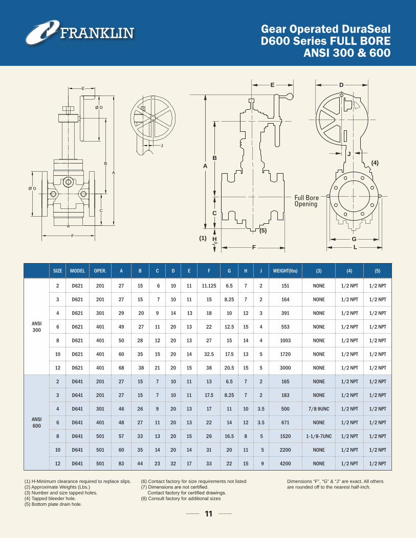
SIZE MODEL OPER. A B C D E F G H J WEIGHT(lbs) (3) (4) (5)
Dimensions “F”, “G” & “J” are exact. All others are rounded off to the nearest half-inch.
(1) H-Minimum clearance required to replace slips.(2) Approximate Weights (Lbs.)(3) Number and size tapped holes.(4) Tapped bleeder hole.(5) Bottom plate drain hole.
(6) Contact factory for size requirements not listed(7) Dimensions are not certified. Contact factory for certified drawings.(8) Consult factory for additional sizes
Gear Operated DuraSealD600 Series FULL BORE
ANSI 300 & 600
ANSI300
2 D621 201 27 15 6 10 11 11.125 6.5 7 2 151 NONE 1/2 NPT 1/2 NPT
3 D621 201 27 15 7 10 11 15 8.25 7 2 164 NONE 1/2 NPT 1/2 NPT
4 D621 301 29 20 9 14 13 18 10 12 3 391 NONE 1/2 NPT 1/2 NPT
6 D621 401 49 27 11 20 13 22 12.5 15 4 553 NONE 1/2 NPT 1/2 NPT
8 D621 401 50 28 12 20 13 27 15 14 4 1003 NONE 1/2 NPT 1/2 NPT
10 D621 401 60 35 15 20 14 32.5 17.5 13 5 1720 NONE 1/2 NPT 1/2 NPT
12 D621 401 68 38 21 20 15 38 20.5 15 5 3000 NONE 1/2 NPT 1/2 NPT
ANSI600
2 D641 201 27 15 7 10 11 13 6.5 7 2 165 NONE 1/2 NPT 1/2 NPT
3 D641 201 27 15 7 10 11 17.5 8.25 7 2 183 NONE 1/2 NPT 1/2 NPT
4 D641 301 46 26 9 20 13 17 11 10 3.5 500 7/8 9UNC 1/2 NPT 1/2 NPT
6 D641 401 48 27 11 20 13 22 14 12 3.5 671 NONE 1/2 NPT 1/2 NPT
8 D641 501 57 33 13 20 15 26 16.5 8 5 1520 1-1/8-7UNC 1/2 NPT 1/2 NPT
10 D641 501 60 35 14 20 14 31 20 11 5 2200 NONE 1/2 NPT 1/2 NPT
12 D641 501 83 44 23 32 17 33 22 15 9 4200 NONE 1/2 NPT 1/2 NPT
11
B
A
D
H
C
FG
(4)
(1)(5)
DE
J
G
C
F L
BA
H(1)(5)
(4)
TYPICAL HAND OPERATED VALVE TYPICAL GEAR OPERATED VALVE
Full Bore Opening
F
Ø D
B
A
C
Ø G
E
J
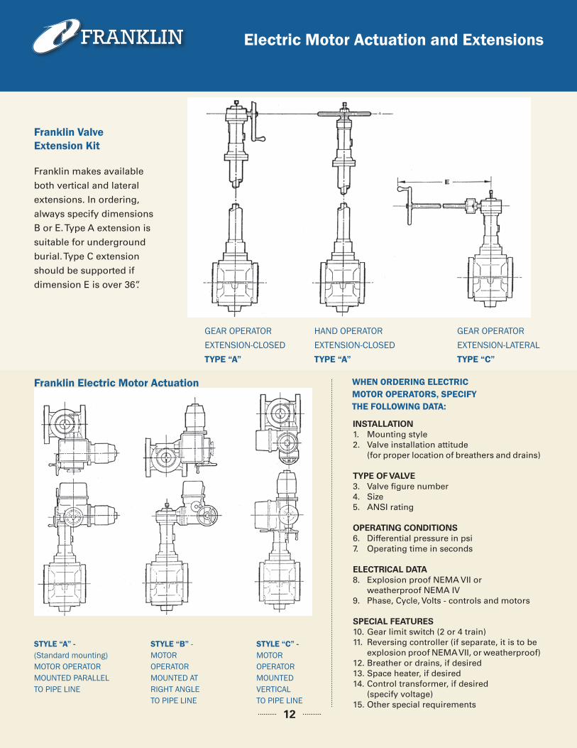
Electric Motor Actuation and Extensions
Franklin makes available
both vertical and lateral
extensions. In ordering,
always specify dimensions
B or E. Type A extension is
suitable for underground
burial. Type C extension
should be supported if
dimension E is over 36”.
INSTALLATION1. Mounting style2. Valve installation attitude (for proper location of breathers and drains)
TYPE OF VALVE3. Valve figure number4. Size5. ANSI rating
OPERATING CONDITIONS6. Differential pressure in psi7. Operating time in seconds
ELECTRICAL DATA8. Explosion proof NEMA VII or weatherproof NEMA IV9. Phase, Cycle, Volts - controls and motors
SPECIAL FEATURES10. Gear limit switch (2 or 4 train)11. Reversing controller (if separate, it is to be explosion proof NEMA VII, or weatherproof)12. Breather or drains, if desired13. Space heater, if desired14. Control transformer, if desired (specify voltage)15. Other special requirements
HAND OPERATOREXTENSION-CLOSED TYPE “A”
GEAR OPERATOREXTENSION-LATERAL TYPE “C”
GEAR OPERATOREXTENSION-CLOSED TYPE “A”
STYLE “A” - (Standard mounting) MOTOR OPERATOR MOUNTED PARALLEL TO PIPE LINE
STYLE “B” - MOTOR OPERATOR MOUNTED AT RIGHT ANGLE TO PIPE LINE
WHEN ORDERING ELECTRIC MOTOR OPERATORS, SPECIFY THE FOLLOWING DATA:
STYLE “C” - MOTOR OPERATOR MOUNTED VERTICAL TO PIPE LINE
Franklin Valve Extension Kit
Franklin Electric Motor Actuation
12
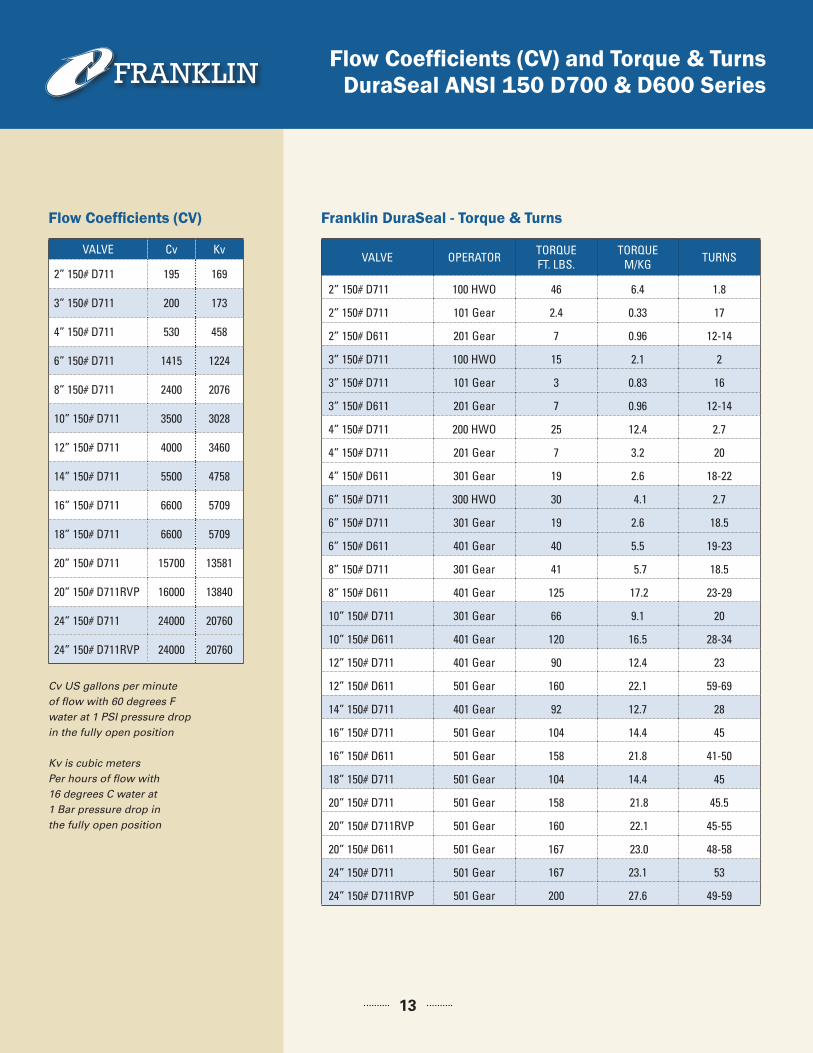
Flow Coefficients (CV) and Torque & TurnsDuraSeal ANSI 150 D700 & D600 Series
Franklin DuraSeal - Torque & Turns
Flow Coefficients (CV)
VALVE Cv Kv
2” 150# D711 195 169
3” 150# D711 200 173
4” 150# D711 530 458
6” 150# D711 1415 1224
8” 150# D711 2400 2076
10” 150# D711 3500 3028
12” 150# D711 4000 3460
14” 150# D711 5500 4758
16” 150# D711 6600 5709
18” 150# D711 6600 5709
20” 150# D711 15700 13581
20” 150# D711RVP 16000 13840
24” 150# D711 24000 20760
24” 150# D711RVP 24000 20760
VALVE OPERATOR TORQUEFT. LBS.
TORQUEM/KG TURNS
2” 150# D711 100 HWO 46 6.4 1.8
2” 150# D711 101 Gear 2.4 0.33 17
2” 150# D611 201 Gear 7 0.96 12-14
3” 150# D711 100 HWO 15 2.1 2
3” 150# D711 101 Gear 3 0.83 16
3” 150# D611 201 Gear 7 0.96 12-14
4” 150# D711 200 HWO 25 12.4 2.7
4” 150# D711 201 Gear 7 3.2 20
4” 150# D611 301 Gear 19 2.6 18-22
6” 150# D711 300 HWO 30 4.1 2.7
6” 150# D711 301 Gear 19 2.6 18.5
6” 150# D611 401 Gear 40 5.5 19-23
8” 150# D711 301 Gear 41 5.7 18.5
8” 150# D611 401 Gear 125 17.2 23-29
10” 150# D711 301 Gear 66 9.1 20
10” 150# D611 401 Gear 120 16.5 28-34
12” 150# D711 401 Gear 90 12.4 23
12” 150# D611 501 Gear 160 22.1 59-69
14” 150# D711 401 Gear 92 12.7 28
16” 150# D711 501 Gear 104 14.4 45
16” 150# D611 501 Gear 158 21.8 41-50
18” 150# D711 501 Gear 104 14.4 45
20” 150# D711 501 Gear 158 21.8 45.5
20” 150# D711RVP 501 Gear 160 22.1 45-55
20” 150# D611 501 Gear 167 23.0 48-58
24” 150# D711 501 Gear 167 23.1 53
24” 150# D711RVP 501 Gear 200 27.6 49-59
Cv US gallons per minute of flow with 60 degrees F water at 1 PSI pressure drop in the fully open position
Kv is cubic metersPer hours of flow with16 degrees C water at 1 Bar pressure drop in the fully open position
13
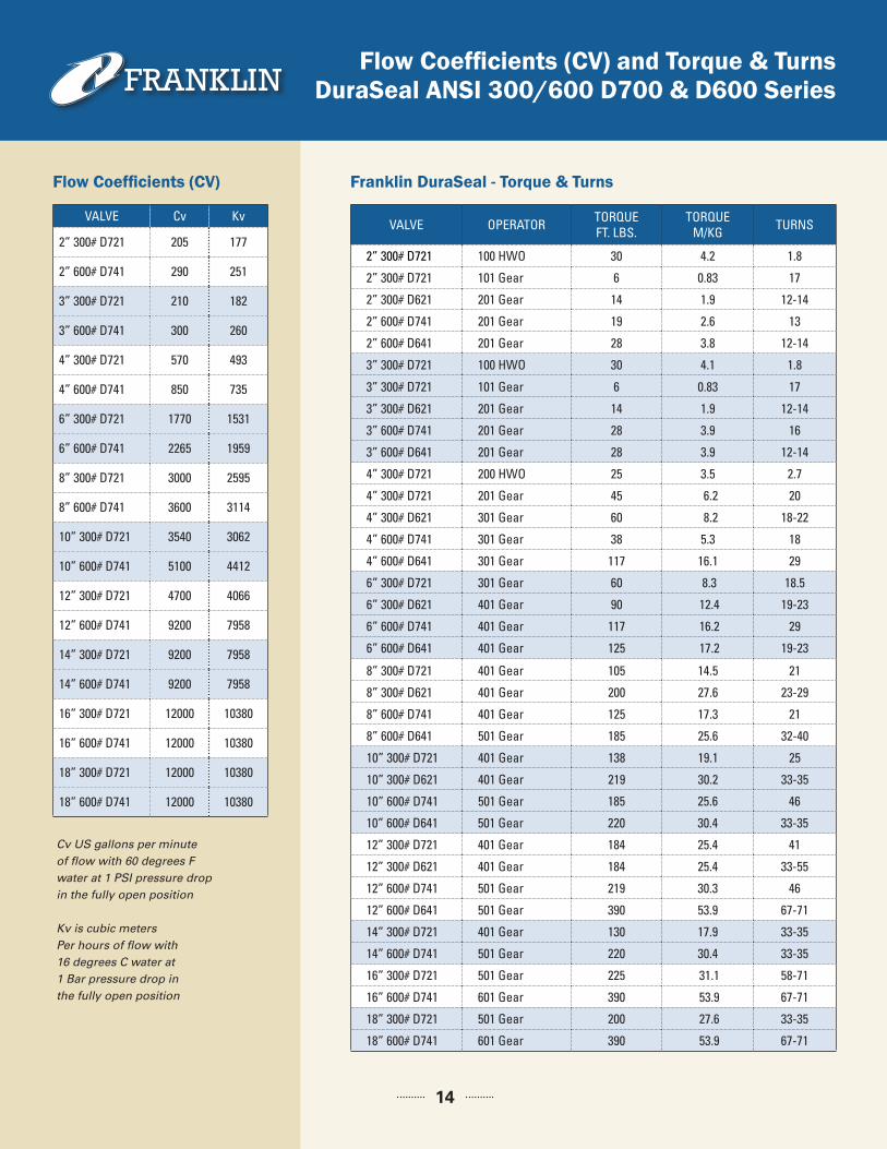
Flow Coefficients (CV) and Torque & TurnsDuraSeal ANSI 300/600 D700 & D600 Series
Franklin DuraSeal - Torque & Turns
Flow Coefficients (CV)
VALVE Cv Kv
2” 300# D721 205 177
2” 600# D741 290 251
3” 300# D721 210 182
3” 600# D741 300 260
4” 300# D721 570 493
4” 600# D741 850 735
6” 300# D721 1770 1531
6” 600# D741 2265 1959
8” 300# D721 3000 2595
8” 600# D741 3600 3114
10” 300# D721 3540 3062
10” 600# D741 5100 4412
12” 300# D721 4700 4066
12” 600# D741 9200 7958
14” 300# D721 9200 7958
14” 600# D741 9200 7958
16” 300# D721 12000 10380
16” 600# D741 12000 10380
18” 300# D721 12000 10380
18” 600# D741 12000 10380
VALVE OPERATOR TORQUEFT. LBS.
TORQUEM/KG TURNS
2” 300# D721 100 HWO 30 4.2 1.8
2” 300# D721 101 Gear 6 0.83 17
2” 300# D621 201 Gear 14 1.9 12-14
2” 600# D741 201 Gear 19 2.6 13
2” 600# D641 201 Gear 28 3.8 12-14
3” 300# D721 100 HWO 30 4.1 1.8
3” 300# D721 101 Gear 6 0.83 17
3” 300# D621 201 Gear 14 1.9 12-14
3” 600# D741 201 Gear 28 3.9 16
3” 600# D641 201 Gear 28 3.9 12-14
4” 300# D721 200 HWO 25 3.5 2.7
4” 300# D721 201 Gear 45 6.2 20
4” 300# D621 301 Gear 60 8.2 18-22
4” 600# D741 301 Gear 38 5.3 18
4” 600# D641 301 Gear 117 16.1 29
6” 300# D721 301 Gear 60 8.3 18.5
6” 300# D621 401 Gear 90 12.4 19-23
6” 600# D741 401 Gear 117 16.2 29
6” 600# D641 401 Gear 125 17.2 19-23
8” 300# D721 401 Gear 105 14.5 21
8” 300# D621 401 Gear 200 27.6 23-29
8” 600# D741 401 Gear 125 17.3 21
8” 600# D641 501 Gear 185 25.6 32-40
10” 300# D721 401 Gear 138 19.1 25
10” 300# D621 401 Gear 219 30.2 33-35
10” 600# D741 501 Gear 185 25.6 46
10” 600# D641 501 Gear 220 30.4 33-35
12” 300# D721 401 Gear 184 25.4 41
12” 300# D621 401 Gear 184 25.4 33-55
12” 600# D741 501 Gear 219 30.3 46
12” 600# D641 501 Gear 390 53.9 67-71
14” 300# D721 401 Gear 130 17.9 33-35
14” 600# D741 501 Gear 220 30.4 33-35
16” 300# D721 501 Gear 225 31.1 58-71
16” 600# D741 601 Gear 390 53.9 67-71
18” 300# D721 501 Gear 200 27.6 33-35
18” 600# D741 601 Gear 390 53.9 67-71
14
Cv US gallons per minute of flow with 60 degrees F water at 1 PSI pressure drop in the fully open position
Kv is cubic metersPer hours of flow with16 degrees C water at 1 Bar pressure drop in the fully open position
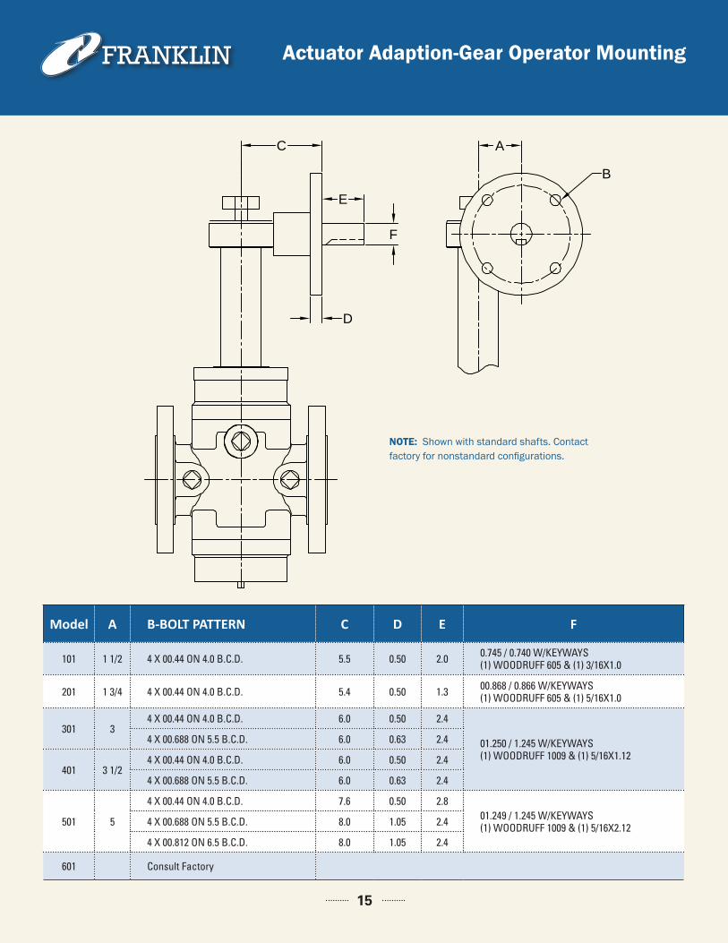
Actuator Adaption-Gear Operator Mounting
C
E
F
D
A
B
Model A B-BOLT PATTERN C D E F
101 1 1/2 4 X 00.44 ON 4.0 B.C.D. 5.5 0.50 2.0 0.745 / 0.740 W/KEYWAYS (1) WOODRUFF 605 & (1) 3/16X1.0
201 1 3/4 4 X 00.44 ON 4.0 B.C.D. 5.4 0.50 1.3 00.868 / 0.866 W/KEYWAYS (1) WOODRUFF 605 & (1) 5/16X1.0
301 34 X 00.44 ON 4.0 B.C.D. 6.0 0.50 2.4
01.250 / 1.245 W/KEYWAYS (1) WOODRUFF 1009 & (1) 5/16X1.12
4 X 00.688 ON 5.5 B.C.D. 6.0 0.63 2.4
401 3 1/24 X 00.44 ON 4.0 B.C.D. 6.0 0.50 2.4
4 X 00.688 ON 5.5 B.C.D. 6.0 0.63 2.4
501 5
4 X 00.44 ON 4.0 B.C.D. 7.6 0.50 2.801.249 / 1.245 W/KEYWAYS (1) WOODRUFF 1009 & (1) 5/16X2.124 X 00.688 ON 5.5 B.C.D. 8.0 1.05 2.4
4 X 00.812 ON 6.5 B.C.D. 8.0 1.05 2.4
601 Consult Factory
NOTE: Shown with standard shafts. Contact factory for nonstandard configurations.
15
DTR Operation
16
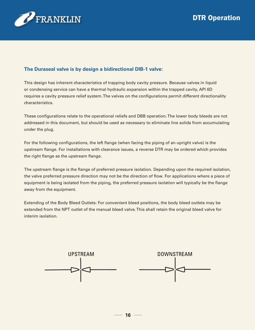
The Duraseal valve is by design a bidirectional DIB-1 valve:
This design has inherent characteristics of trapping body cavity pressure. Because valves in liquid
or condensing service can have a thermal hydraulic expansion within the trapped cavity, API 6D
requires a cavity pressure relief system. The valves on the configurations permit different directionality
characteristics.
These configurations relate to the operational reliefs and DBB operation. The lower body bleeds are not
addressed in this document, but should be used as necessary to eliminate line solids from accumulating
under the plug.
For the following configurations, the left flange (when facing the piping of an upright valve) is the
upstream flange. For installations with clearance issues, a reverse DTR may be ordered which provides
the right flange as the upstream flange.
The upstream flange is the flange of preferred pressure isolation. Depending upon the required isolation,
the valve preferred pressure direction may not be the direction of flow. For applications where a piece of
equipment is being isolated from the piping, the preferred pressure isolation will typically be the flange
away from the equipment.
Extending of the Body Bleed Outlets: For convenient bleed positions, the body bleed outlets may be
extended from the NPT outlet of the manual bleed valve. This shall retain the original bleed valve for
interim isolation.
BODY BLEED OUTLET
BODY CAVITY
MANUALBLEEDVALVE
UPSTREAM DOWNSTREAM
DTR - Manual Bleed
17
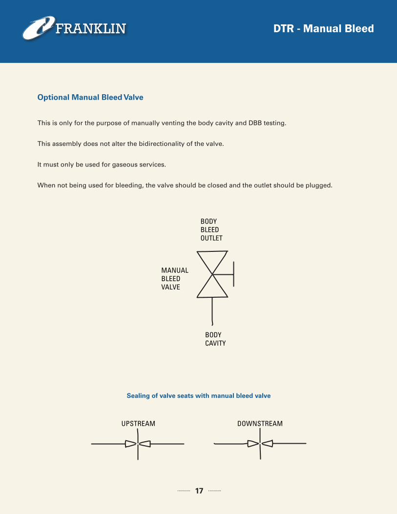
This is only for the purpose of manually venting the body cavity and DBB testing.
This assembly does not alter the bidirectionality of the valve.
It must only be used for gaseous services.
When not being used for bleeding, the valve should be closed and the outlet should be plugged.
Optional Manual Bleed Valve
Sealing of valve seats with manual bleed valve
BODY BLEED OUTLET
BODY CAVITY
MANUALBLEEDVALVE
UPSTREAM DOWNSTREAM
DTR - Standard Configuration
18
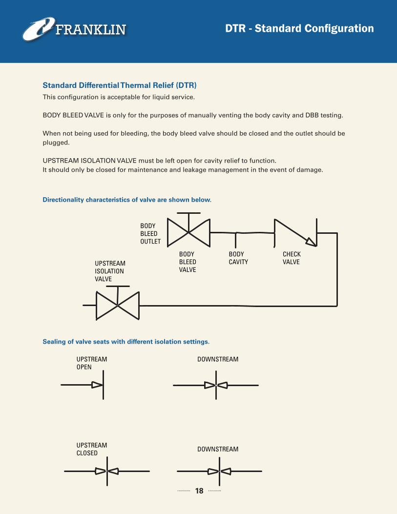
This configuration is acceptable for liquid service.
BODY BLEED VALVE is only for the purposes of manually venting the body cavity and DBB testing.
When not being used for bleeding, the body bleed valve should be closed and the outlet should be plugged.
UPSTREAM ISOLATION VALVE must be left open for cavity relief to function. It should only be closed for maintenance and leakage management in the event of damage.
Standard Differential Thermal Relief (DTR)
Directionality characteristics of valve are shown below.
Sealing of valve seats with different isolation settings.
BODY BLEED OUTLET
UPSTREAMISOLATIONVALVE
UPSTREAMOPEN
DOWNSTREAM
DOWNSTREAMUPSTREAMCLOSED
BODY BLEED VALVE
BODY CAVITY
CHECK VALVE
DTR - Line Relieving
19
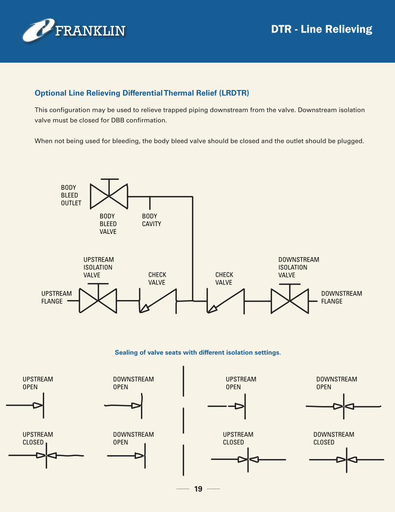
This configuration may be used to relieve trapped piping downstream from the valve. Downstream isolation
valve must be closed for DBB confirmation.
When not being used for bleeding, the body bleed valve should be closed and the outlet should be plugged.
Optional Line Relieving Differential Thermal Relief (LRDTR)
BODY BLEED OUTLET
UPSTREAMFLANGE
UPSTREAMOPEN
DOWNSTREAMOPEN
UPSTREAMOPEN
DOWNSTREAMOPEN
UPSTREAMCLOSED
DOWNSTREAMOPEN
UPSTREAMCLOSED
DOWNSTREAMCLOSED
DOWNSTREAMFLANGE
BODY BLEED VALVE
UPSTREAMISOLATIONVALVE
DOWNSTREAMISOLATIONVALVE
BODY CAVITY
CHECK VALVE
CHECK VALVE
Sealing of valve seats with different isolation settings.
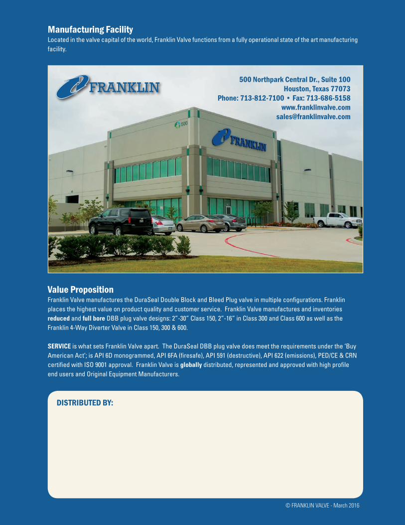
Manufacturing FacilityLocated in the valve capital of the world, Franklin Valve functions from a fully operational state of the art manufacturing facility.
Value PropositionFranklin Valve manufactures the DuraSeal Double Block and Bleed Plug valve in multiple configurations. Franklin places the highest value on product quality and customer service. Franklin Valve manufactures and inventories reduced and full bore DBB plug valve designs: 2”-30” Class 150, 2”-16” in Class 300 and Class 600 as well as the Franklin 4-Way Diverter Valve in Class 150, 300 & 600.
SERVICE is what sets Franklin Valve apart. The DuraSeal DBB plug valve does meet the requirements under the ‘Buy American Act’; is API 6D monogrammed, API 6FA (firesafe), API 591 (destructive), API 622 (emissions), PED/CE & CRN certified with ISO 9001 approval. Franklin Valve is globally distributed, represented and approved with high profile end users and Original Equipment Manufacturers.
DISTRIBUTED BY:
500 Northpark Central Dr., Suite 100Houston, Texas 77073
Phone: 713-812-7100 • Fax: 713-686-5158www.franklinvalve.com
© FRANKLIN VALVE - March 2016