Embed Size (px)
Citation preview
1
flowserve.com
Durco T4E Lined Plug Valves Fluoropolymer Lined Valves
Experience In Motion
2
®
History
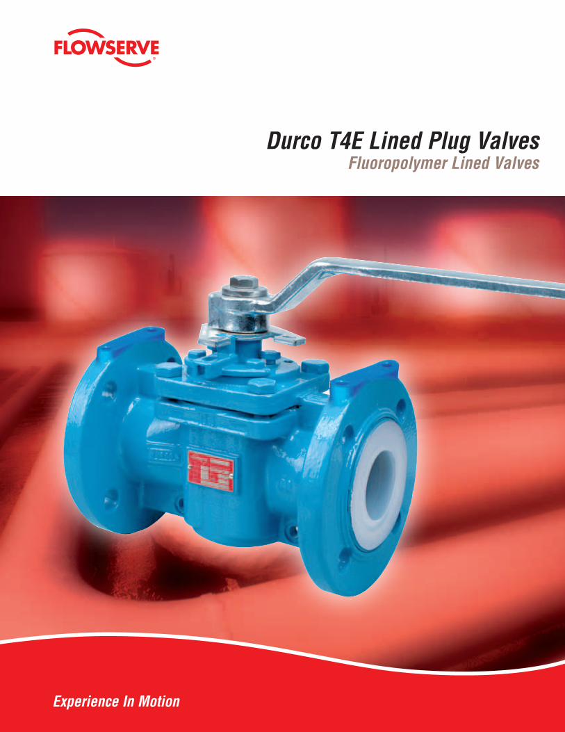
Available in a Broad Size Range and
• T4E1 ASME Class 150 is available in sizes ½" through 12"
• T4E2 DIN PN 16 is available in sizes DN 15 through DN 300
• T4E3 ASME Class 300 is available in sizes ½" through 10"
Extended Pressure Classes • T4E1 and T4E2 rated 180 psi @400 °F (12.4 bar @ 204 °C), 250 psi @ 100 °F (17.2 bar @ 100 °C)
• T4E3 rated 320 psi @ 400 °F (22 bar @ 204 °C), 740 psi @ 100 °F (51 bar @ 100 °C)
Flowserve Durco T4E valves have been designed and developed with the latest technology and are the most preferred fluoropolymer lined valves in the global chemical industries.Durco T4E valves provide maximumcorrosion resistance and the elimination of product contamination at a reasonable cost.
Available with pneumatic or electric actuators for On-Off or modulating control applications.All T4E valve series are rated to 4 Kpa (30 inches Hg) vacuum at ambient temperature.
3
flowserve.com
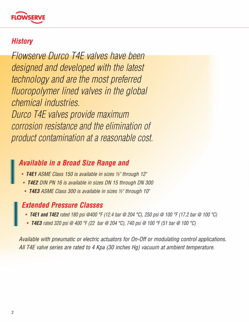
Double-D plug stem accepts most standard actuation equipment
T-Slots in Critical Areas to Lock Liner Against Body Wall Advantage will be a tight and perfect fit of the liner and an additional support during vacuum service
High Quality PFA Liner Protects the body and forms the flange gasket. The PFA liner is resistant against a wide variation of chemical products
Raised LipPrevents cold flow outward
Features
Dynamic, Self-adjusting, Self-Energizing PFA or TFMreverse lip diaphragm
Solid Encapsulated PFA Molded Plug All plug inserts have anchor holes to ensure a strong adhesion of the plug PFA liner material even under extreme cycling conditions
Anti-Rotation LugsHelp to eliminate stress on fasteners during actuation
Large PortsOffer good Cv values. Reduced frictional losses & pressure drop
Standard Lockable Wrenches Allows valve to be locking in
open or closed position
Inline adjustmentStops thru-line leakage
ISO 5211 Mounting PadUniversal flange for easy
actuation mounting
Grounding springTo avoid build-up of
static electricity
4
®
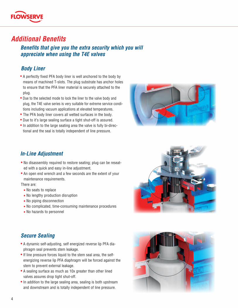
• A dynamic self-adjusting, self energized reverse lip PFA dia-phragm seal prevents stem leakage.
• If line pressure forces liquid to the stem seal area, the self-energizing reverse lip PFA diaphragm will be forced against the stem to prevent external leakage.
• A sealing surface as much as 10x greater than other lined valves assures drop tight shut-off.
• In addition to the large sealing area, sealing is both upstream and downstream and is totally independent of line pressure.
Secure Sealing
In-Line Adjustment
Body Liner
Additional BenefitsBenefits that give you the extra security which you will appreciate when using the T4E valves
• A perfectly fixed PFA body liner is well anchored to the body by means of machined T-slots. The plug substrate has anchor holes to ensure that the PFA liner material is securely attached to the plug.
• Due to the selected mode to lock the liner to the valve body and plug, the T4E valve series is very suitable for extreme service condi-tions including vacuum applications at elevated temperatures.
• The PFA body liner covers all wetted surfaces in the body.• Due to it’s large sealing surface a tight shut-off is assured.• In addition to the large seating area the valve is fully bi-direc-
tional and the seal is totally independent of line pressure.
• No disassembly required to restore seating; plug can be reseat-ed with a quick and easy in-line adjustment.
• An open end wrench and a few seconds are the extent of your maintenance requirements.
There are: No seats to replace No lengthy production disruption No piping disconnection No complicated, time-consuming maintenance procedures No hazards to personnel
5
flowserve.com
22 bar
24 bar
26 bar
28 bar
30 bar
32 bar
34 bar
36 bar
38 bar
40 bar
42 bar
44 bar
46 bar
48 bar
50 bar
52 bar
320 psi
360 psi
400 psi
440 psi
480 psi
520 psi
560 psi
600 psi
640 psi
680 psi
720 psi
760 psi
-20°
F
0°F
20°F
40°F
60°F
80°F
100°
F
120°
F
140°
F
160°
F
180°
F
200°
F
220°
F
240°
F
260°
F
280°
F
300°
F
320°
F
340°
F
360°
F
380°
F
400°
F
Pres
sure
Temperature
-29°
C
-18°
C
-7°C
4°C
16°C
27°C
38°C
49°C
60°C
71°C
82°C
93°C
104°
C
116°
C
127°
C
138°
C
149°
C
160°
C
171°
C
182°
C
193°
C
204°
C
10 bar
11 bar
12 bar
13 bar
14 bar
15 bar
16 bar
17 bar
18 bar
19 bar
20 bar
145 psi
170 psi
195 psi
220 psi
245 psi
270 psi
295 psi
-20°
F
0°F
20°F
40°F
60°F
80°F
100°
F
120°
F
140°
F
160°
F
180°
F
200°
F
220°
F
240°
F
260°
F
280°
F
300°
F
320°
F
340°
F
360°
F
380°
F
400°
F
Pres
sure
Temperature
-29°
C
-18°
C
-7°C
4°C
16°C
27°C
38°C
49°C
60°C
71°C
82°C
93°C
104°
C
116°
C
127°
C
138°
C
149°
C
160°
C
171°
C
182°
C
193°
C
204°
C
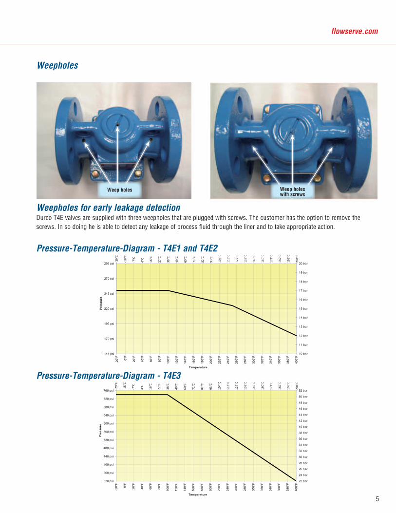
Weepholes
Weepholes for early leakage detectionDurco T4E valves are supplied with three weepholes that are plugged with screws. The customer has the option to remove the screws. In so doing he is able to detect any leakage of process fluid through the liner and to take appropriate action.
Pressure-Temperature-Diagram - T4E1 and T4E2
Pressure-Temperature-Diagram - T4E3
Weep holes Weep holeswith screws
6
®
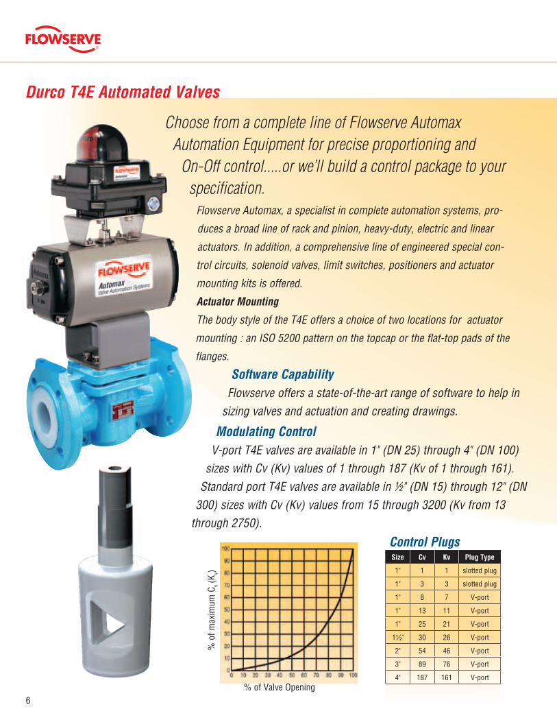
Durco T4E Automated Valves
Choose from a complete line of Flowserve Automax Automation Equipment for precise proportioning and
On-Off control.....or we’ll build a control package to your specification.
Flowserve Automax, a specialist in complete automation systems, pro-
duces a broad line of rack and pinion, heavy-duty, electric and linear
actuators. In addition, a comprehensive line of engineered special con-
trol circuits, solenoid valves, limit switches, positioners and actuator
mounting kits is offered.
Actuator Mounting
The body style of the T4E offers a choice of two locations for actuator
mounting : an ISO 5200 pattern on the topcap or the flat-top pads of the
flanges.
Software CapabilityFlowserve offers a state-of-the-art range of software to help in
sizing valves and actuation and creating drawings.
Modulating ControlV-port T4E valves are available in 1" (DN 25) through 4" (DN 100)
sizes with Cv (Kv) values of 1 through 187 (Kv of 1 through 161). Standard port T4E valves are available in ½" (DN 15) through 12" (DN
300) sizes with Cv (Kv) values from 15 through 3200 (Kv from 13 through 2750).
% of Valve Opening
% o
f max
imum
Cv (K
v)
Control PlugsSize Cv Kv Plug Type
1" 1 1 slotted plug
1" 3 3 slotted plug
1" 8 7 V-port
1" 13 11 V-port
1" 25 21 V-port
1½" 30 26 V-port
2" 54 46 V-port
3" 89 76 V-port
4" 187 161 V-port
7
flowserve.com
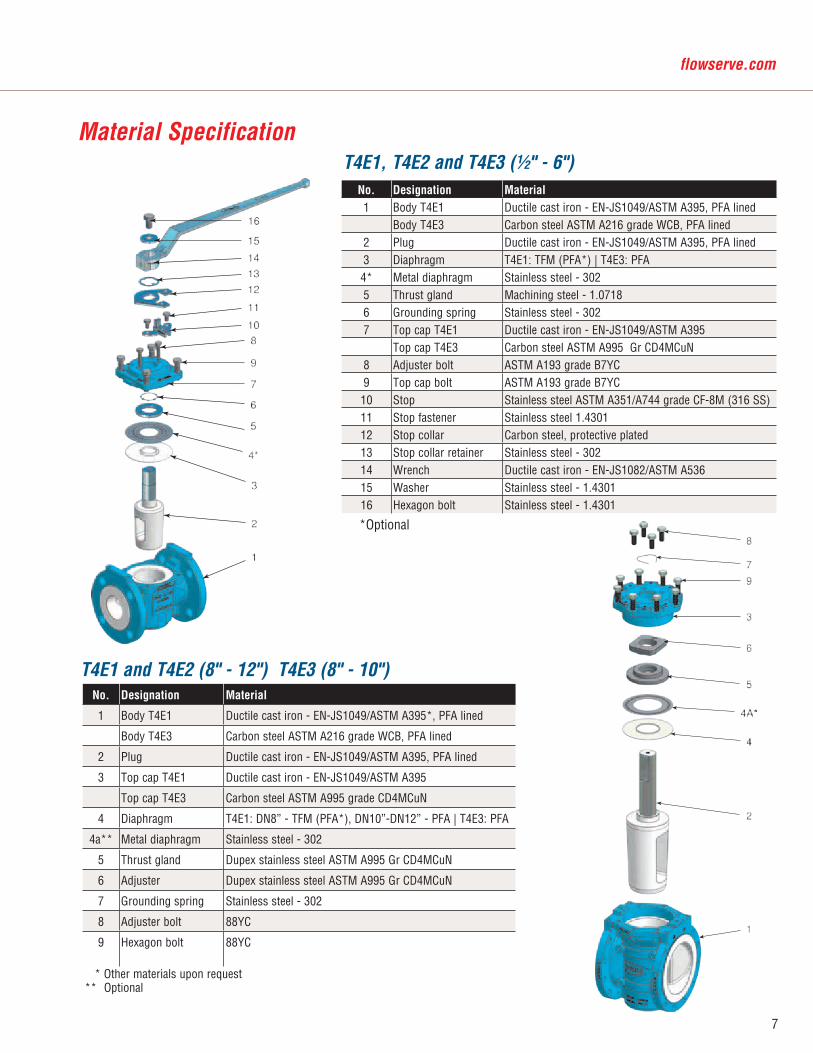
Material SpecificationT4E1, T4E2 and T4E3 (½" - 6")
T4E1 and T4E2 (8" - 12") T4E3 (8" - 10")No. Designation Material
1 Body T4E1 Ductile cast iron - EN-JS1049/ASTM A395*, PFA lined
Body T4E3 Carbon steel ASTM A216 grade WCB, PFA lined
2 Plug Ductile cast iron - EN-JS1049/ASTM A395, PFA lined
3 Top cap T4E1 Ductile cast iron - EN-JS1049/ASTM A395
Top cap T4E3 Carbon steel ASTM A995 grade CD4MCuN
4 Diaphragm T4E1: DN8” - TFM (PFA*), DN10”-DN12” - PFA | T4E3: PFA
4a** Metal diaphragm Stainless steel - 302
5 Thrust gland Dupex stainless steel ASTM A995 Gr CD4MCuN
6 Adjuster Dupex stainless steel ASTM A995 Gr CD4MCuN
7 Grounding spring Stainless steel - 302
8 Adjuster bolt 88YC
9 Hexagon bolt 88YC
* Other materials upon request** Optional
*Optional
No. Designation Material1 Body T4E1 Ductile cast iron - EN-JS1049/ASTM A395, PFA lined
Body T4E3 Carbon steel ASTM A216 grade WCB, PFA lined2 Plug Ductile cast iron - EN-JS1049/ASTM A395, PFA lined3 Diaphragm T4E1: TFM (PFA*) | T4E3: PFA4* Metal diaphragm Stainless steel - 3025 Thrust gland Machining steel - 1.07186 Grounding spring Stainless steel - 3027 Top cap T4E1 Ductile cast iron - EN-JS1049/ASTM A395
Top cap T4E3 Carbon steel ASTM A995 Gr CD4MCuN8 Adjuster bolt ASTM A193 grade B7YC9 Top cap bolt ASTM A193 grade B7YC10 Stop Stainless steel ASTM A351/A744 grade CF-8M (316 SS)11 Stop fastener Stainless steel 1.430112 Stop collar Carbon steel, protective plated13 Stop collar retainer Stainless steel - 30214 Wrench Ductile cast iron - EN-JS1082/ASTM A53615 Washer Stainless steel - 1.430116 Hexagon bolt Stainless steel - 1.4301
8
®
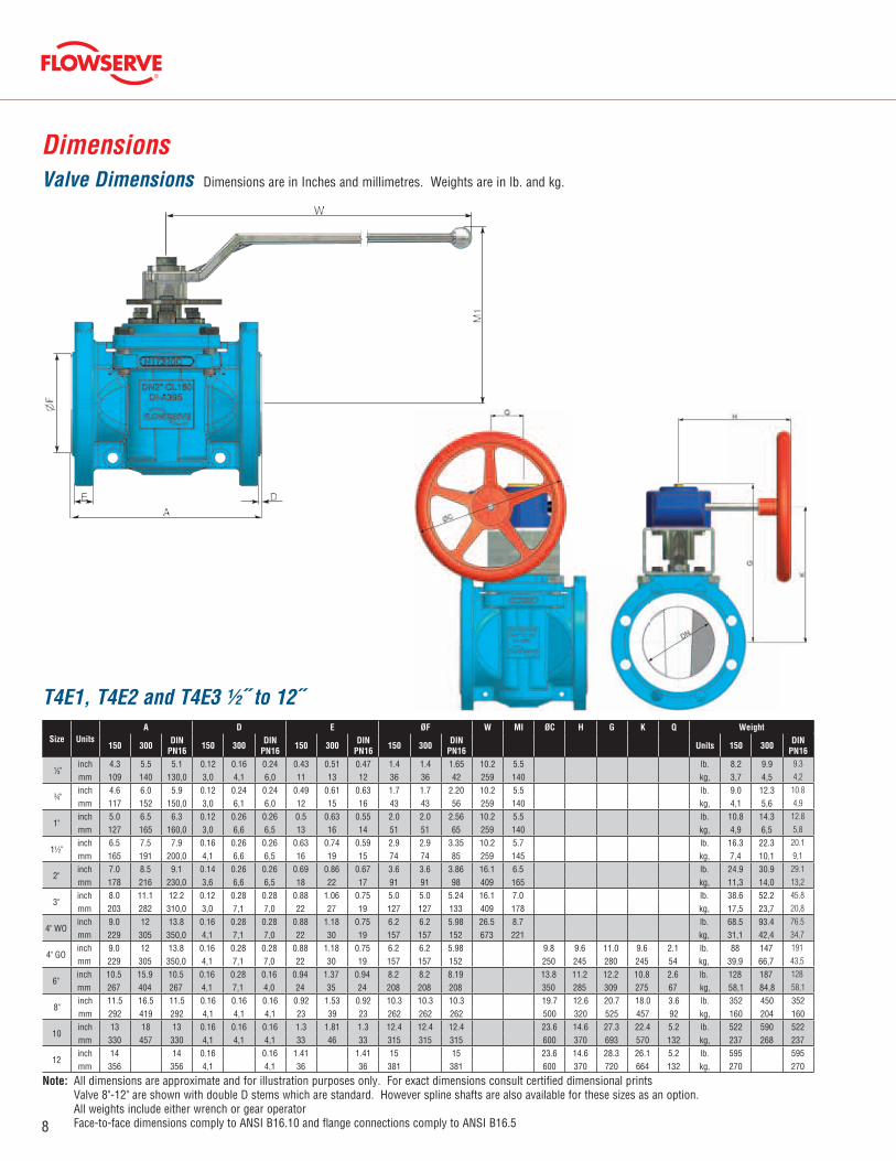
Dimensions
All dimensions are approximate and for illustration purposes only. For exact dimensions consult certified dimensional prints Valve 8"-12" are shown with double D stems which are standard. However spline shafts are also available for these sizes as an option. All weights include either wrench or gear operator Face-to-face dimensions comply to ANSI B16.10 and flange connections comply to ANSI B16.5
T4E1, T4E2 and T4E3 ½˝ to 12˝
Valve Dimensions
Size UnitsA D E ØF W MI ØC H G K Q Weight
150 300 DIN PN16 150 300 DIN
PN16 150 300 DIN PN16 150 300 DIN
PN16 Units 150 300 DIN PN16
�"inch 4.3 5.5 5.1 0.12 0.16 0.24 0.43 0.51 0.47 1.4 1.4 1.65 10.2 5.5 lb. 8.2 9.9 9.3
mm 109 140 130,0 3,0 4,1 6,0 11 13 12 36 36 42 259 140 kg, 3,7 4,5 4,2
�"inch 4.6 6.0 5.9 0.12 0.24 0.24 0.49 0.61 0.63 1.7 1.7 2.20 10.2 5.5 lb. 9.0 12.3 10.8
mm 117 152 150,0 3,0 6,1 6,0 12 15 16 43 43 56 259 140 kg, 4,1 5,6 4,9
1"inch 5.0 6.5 6.3 0.12 0.26 0.26 0.5 0.63 0.55 2.0 2.0 2.56 10.2 5.5 lb. 10.8 14.3 12.8
mm 127 165 160,0 3,0 6,6 6,5 13 16 14 51 51 65 259 140 kg, 4,9 6,5 5,8
1�"inch 6.5 7.5 7.9 0.16 0.26 0.26 0.63 0.74 0.59 2.9 2.9 3.35 10.2 5.7 lb. 16.3 22.3 20.1
mm 165 191 200,0 4,1 6,6 6,5 16 19 15 74 74 85 259 145 kg, 7,4 10,1 9,1
2"inch 7.0 8.5 9.1 0.14 0.26 0.26 0.69 0.86 0.67 3.6 3.6 3.86 16.1 6.5 lb. 24.9 30.9 29.1
mm 178 216 230,0 3,6 6,6 6,5 18 22 17 91 91 98 409 165 kg, 11,3 14,0 13,2
3"inch 8.0 11.1 12.2 0.12 0.28 0.28 0.88 1.06 0.75 5.0 5.0 5.24 16.1 7.0 lb. 38.6 52.2 45.8
mm 203 282 310,0 3,0 7,1 7,0 22 27 19 127 127 133 409 178 kg, 17,5 23,7 20,8
4" WOinch 9.0 12 13.8 0.16 0.28 0.28 0.88 1.18 0.75 6.2 6.2 5.98 26.5 8.7 lb. 68.5 93.4 76.5
mm 229 305 350,0 4,1 7,1 7,0 22 30 19 157 157 152 673 221 kg, 31,1 42,4 34,7
4" GOinch 9.0 12 13.8 0.16 0.28 0.28 0.88 1.18 0.75 6.2 6.2 5.98 9.8 9.6 11.0 9.6 2.1 lb. 88 147 191
mm 229 305 350,0 4,1 7,1 7,0 22 30 19 157 157 152 250 245 280 245 54 kg, 39,9 66,7 43,5
6"inch 10.5 15.9 10.5 0.16 0.28 0.16 0.94 1.37 0.94 8.2 8.2 8.19 13.8 11.2 12.2 10.8 2.6 lb. 128 187 128
mm 267 404 267 4,1 7,1 4,0 24 35 24 208 208 208 350 285 309 275 67 kg, 58,1 84,8 58,1
8"inch 11.5 16.5 11.5 0.16 0.16 0.16 0.92 1.53 0.92 10.3 10.3 10.3 19.7 12.6 20.7 18.0 3.6 lb. 352 450 352mm 292 419 292 4,1 4,1 4,1 23 39 23 262 262 262 500 320 525 457 92 kg, 160 204 160
10inch 13 18 13 0.16 0.16 0.16 1.3 1.81 1.3 12.4 12.4 12.4 23.6 14.6 27.3 22.4 5.2 lb. 522 590 522mm 330 457 330 4,1 4,1 4,1 33 46 33 315 315 315 600 370 693 570 132 kg, 237 268 237
12inch 14 14 0.16 0.16 1.41 1.41 15 15 23.6 14.6 28.3 26.1 5.2 lb. 595 595mm 356 356 4,1 4,1 36 36 381 381 600 370 720 664 132 kg, 270 270
Note:
Dimensions are in Inches and millimetres. Weights are in lb. and kg.

9
flowserve.com
T4E - Dimension sheet for actuator mounting
Top cap mounting acc. to DIN EN ISO 5211
Flange top mounting
E
2
H2
C
P
GSW
J
DN
Adjustmentdown - A1
nxO
B
R
S
ØT
ØT
DN10",12"
Bracket cut
Adjustmentup - A2
ØT
X
Y
MC
GSW
J
Adjustmentdown - A1
T2(M)
DN
Z
Adjustmentup - A2
* no actuator mounting for T4E2 valves
DN SW ØG J H2 CAdjustment F-Size
ØB nxO E ØP R ØS ØTM
(M)T2
X Z YDIN/ISO
T4E1 T4E3 T4E1 T4E3 T4E1 T4E3A1 A2 5211
½"inch 0.65 0.79 0.61 1.52 3.64 0.08 0.08
F051.97 4xM6
- 8 deep1.5 0.51 2.13 0.63 1.38
UNC 1/4-200.35 3.56 4.65 1.83 1.97 2 2
mm 16,6 20 15,5 38,5 92,5 2 2 50 38 13 54 16 35 9 90,5 118 46,5 50 50,8 50,8
¾"inch 0.65 0.79 0.61 1.52 3.64 0.08 0.08
F051.97 4xM6
- 8 deep1.5 0.51 2.13 0.63 1.38
UNC 1/4-200.35 3.92 5 2.03 2.4 2 2
mm 16,6 20 15,5 38,5 92,5 2 2 50 38 13 54 16 35 9 99,6 127 51,5 61 50,8 50,8
1"inch 0.65 0.79 0.61 1.52 3.64 0.08 0.08
F051.97 4xM6
- 8 deep1.5 0.59 2.28 0.79 1.38
UNC 5/16-180.47 4.19 5.35 2.34 2.44 1.75 1.75
mm 16.6 20 15.5 38.7 92.5 2 2 50 38 15 58 20 35 12 106.4 136 59.5 62 44.5 44.5
1½"inch 0.65 0.79 0.75 1.48 4.02 0.08 0.08
F051.97 4xM6
- 8 deep1.5 0.59 2.28 0.79 1.38
UNC 5/16-180.47 5.63 6.38 2.500 3.07 1.75 1.75
mm 16,6 20 19 37,7 102 2 2 50 38 15 58 20 35 12 142,9 162 63,5 78 44,5 44,5
2"inch 0.87 1.07 0.99 1.93 4.84 0.08 0.08
F072.76 4xM8
- 12 deep1.85 0.59 2.64 0.79 2.17
UNC 5/16-180.47 6.19 7.36 3.01 3.25 2.25 2.25
mm 22,2 27,2 25,2 49 123 2 2 70 47 15 67 20 55 12 157,2 187 76,5 82,5 57,2 57,2
3"inch 0.87 1.07 0.99 1.99 5.39 0.12 0.12
F072.76 4xM8
- 12 deep2.13 0.87 3.15 1.02 2.17
UNC 3/8-160.55 7.13 9.87 3.76 4.13 3.5 3.5
mm 22,2 27,2 25,2 50,6 137 3 3 70 54 22 80 26 55 14 181 250,8 95,5 105 88,9 88,9
4"inch 1.42 1.69 1.59 2.76 6.97 0.12 0.12
F104.02 4xM10
- 16 deep2.87 0.87 3.90 1.02 2.76
UNC 7/16-140.63 8 10.63 4.51 5.000 4 4
mm 36 42,8 40,4 70,2 177 3 3 102 73 22 99 26 70 16 203,2 269,9 114,5 127 101,6 101,6
6"inch 1.42 1.69 1.59 2.67 8.23 0.16 0.16
F124.92 4xM12
- 21 deep3.39 1.38 4.96 1.57 3.35
UNC 7/16-140.63 9.44 14.25 5.47 6.26 4 4
mm 36 42,8 40,4 67,7 209 4 4 125 86 35 126 40 85 16 239,7 362 139 159 101,6 101,6
8"inch 1.97 2.5 3.94 6.6 15.8 0.2 0.2
---7.5 8xM16
- 26 deep5.25 2.1 7.48 2.20 5.12
M161.42 10.25 14.82 6.83 7.50 7.69 7.62
mm 50 63,5 100 166,6 402 5 5 190,5 133,4 53 190 56 130 36 260,4 376,4 173,5 190,5 195,2 193,6
10"inch 2.36 3 4.92 8.46 19.49 0.2 0.2
F2510 8xM16
- 26 deep5.13 1.46
--- ---7.87
M201.54 11.57
*8.43
*7.87
*mm 60 76,2 125 214,8 495 5 5 254 130,2 37 200 39 294 214 200
12"inch 2.36 3 4.92 8.48 20.35 0.2 0.2
F2510 8xM16
-26 deep5.13 1.46
--- ---7.87
M201.57 12.28 17.69 9.19 10.55 7.87 6.00
mm 60 76,2 125 215,4 517 5 5 254 130,2 37 200 40 312 449,3 233,5 268 200 152,4
10
®
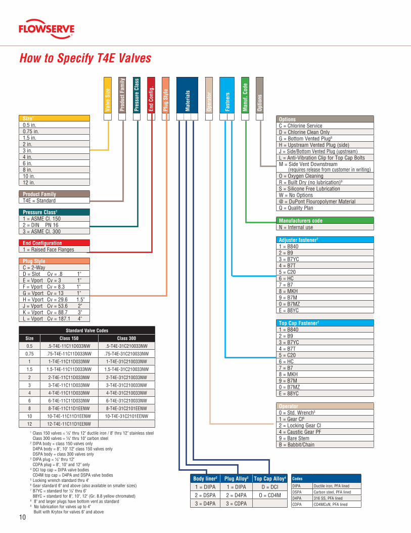
How to Specify T4E Valves
OptionsC = Chlorine ServiceD = Chlorine Clean OnlyG = Bottom Vented Plug8
H = Upstream Vented Plug (side)J = Side/Bottom Vented Plug (upstream)L = Anti-Vibration Clip for Top Cap BoltsM = Side Vent Downstream (requires release from customer in writing)O = Oxygen CleaningR = Built Dry (no lubrication)9
S = Silicone Free LubricationW = No Options@ = DuPont Flouropolymer MaterialQ = Quality Plan
Manufacturers codeN = Internal use
Adjuster fastener7
1 = B8402 = B93 = B7YC4 = B7T5 = C206 = HC7 = B78 = MKH9 = B7M0 = B7MZE = 88YC
Top Cap Fastener7
1 = B8402 = B93 = B7YC4 = B7T5 = C206 = HC7 = B78 = MKH9 = B7M0 = B7MZE = 88YC
Operator0 = Std. Wrench5
1 = Gear Cl6 2 = Locking Gear Cl4 = Caustic Gear PF9 = Bare StemB = Babbit/Chain
Body liner2 Plug Alloy3 Top Cap Alloy4
1 = DIPA 1 = DIPA D = DCI2 = DSPA 2 = D4PA O = CD4M3 = D4PA 3 = CDPA
Standard Valve Codes
Size Class 150 Class 300
0.5 .5-T4E-11C11D033NW .5-T4E-31C210033NW
0.75 .75-T4E-11C11D033NW .75-T4E-31C210033NW
1 1-T4E-11C11D033NW 1-T4E-31C210033NW
1.5 1.5-T4E-11C11D033NW 1.5-T4E-31C210033NW
2 2-T4E-11C11D033NW 2-T4E-31C210033NW
3 3-T4E-11C11D033NW 3-T4E-31C210033NW
4 4-T4E-11C11D033NW 4-T4E-31C210033NW
6 6-T4E-11C11D033NW 6-T4E-31C210033NW
8 8-T4E-11C11D1EENW 8-T4E-31C2101EENW
10 10-T4E-11C11D1EENW 10-T4E-31C2101EENW
12 12-T4E-11C11D1EENW
1 Class 150 valves = ½" thru 12" ductile iron / 8" thru 12" stainless steel Class 300 valves = ½" thru 10" carbon steel2 DIPA body = class 150 valves only D4PA body = 8", 10" 12" class 150 valves only DSPA body = class 300 valves only3 DIPA plug = ½" thru 12" CDPA plug = 8", 10" and 12" only4 DCI top cap = DIPA valve bodies CD4M top cap = D4PA and DSPA valve bodies5 Locking wrench standard thru 4"6 Gear standard 6" and above (also available on smaller sizes)7 B7YC = standard for ½" thru 6" 88YC = standard for 8", 10", 12" (Gr. 8.8 yellow chromated)8 8" and larger plugs have bottom vent as standard9 No lubrication for valves up to 4" Built with Krytox for valves 6" and above
Valv
e Si
ze
Prod
uct F
amily
Pres
sure
Cla
ss
End
Conf
ig.
Plug
Sty
le
Mat
eria
ls
Oper
ator
Fast
ners
Man
uf. C
ode
Optio
ns
Size1
0.5 in.0.75 in.1.5 in.2 in.3 in.4 in.6 in.8 in.10 in.12 in.
Product FamilyT4E = Standard
Pressure Class1
1 = ASME Cl. 1502 = DIN PN 163 = ASME Cl. 300
End Configuration1 = Raised Face Flanges
Plug StyleC = 2-WayD = Slot Cv = .8 1"E = Vport Cv = 3 1"F = Vport Cv = 8.3 1"G = Vport Cv = 13 1"H = Vport Cv = 29.6 1.5"J = Vport Cv = 53.6 2"K = Vport Cv = 88.7 3"L = Vport Cv = 187.1 4"
Codes
DIPA Ductile iron, PFA linedDSPA Carbon steel, PFA linedD4PA 316 SS, PFA linedCDPA CD4MCuN, PFA lined
11
flowserve.com
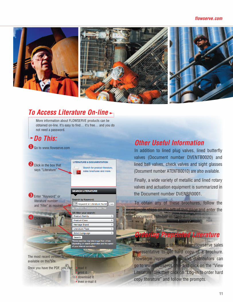
To Access Literature On-line More information about FLOWSERVE products can be obtained on-line. It’s easy to find… it’s free… and you do not need a password.
Do This:Go to www.flowserve.com
Click in the box that says “Literature”
Enter “Keyword” or literature number and “Filter” as required
Click on “Search”
The most recent version of each product bulletin will be available on this site.
Once you have the PDF, you can: • read it • print it • download it • even e-mail it
Ordering Preprinted LiteratureCustomers, please contact your Flowserve sales representative to get hard copy of a brochure. Flowserve representatives and distributors can go to www.flowserve.com and click on the “View Literature” link then click on “Log-in to order hard copy literature” and follow the prompts.
Other Useful InformationIn addition to lined plug valves, lined butterfly valves (Document number DVENTB0020) and lined ball valves, check valves and sight glasses (Document number ATENTB0010) are also available.
Finally, a wide variety of metallic and lined rotary valves and actuation equipment is summarized in the Document number DVENBR0001.
To obtain any of these brochures, follow the simple steps on the left of this page and enter the Document number in Step 3.
12
®
To find your local Flowserve representative, visit www.flowserve.com or call USA 1 800 251 6761
FCD DVENBR0066-01 10/12 Printed in USA.
flowserve.com
Flowserve Corporation has established industry leadership in the design and manufacture of its products. When properly selected, this Flowserve product is designed to perform its intended function safely during its useful life. However, the purchaser or user of Flowserve products should be aware that Flowserve products might be used in numerous applications under a wide variety of industrial service conditions. Although Flowserve can (and often does) provide general guidelines, it cannot provide specific data and warnings for all possible applications. The purchaser/user must therefore assume the ultimate responsibility for the proper sizing and selection, installation, operation, and maintenance of Flowserve products. The purchaser/user should read and understand the Installation Operation Maintenance (IOM) instructions included with the product, and train its employees and contractors in the safe use of Flowserve products in connection with the specific application.
While the information and specifications contained in this literature are believed to be accurate, they are supplied for informative purposes only and should not be considered certified or as a guarantee of satisfactory results by reliance thereon. Nothing contained herein is to be construed as a warranty or guarantee, express or implied, regarding any matter with respect to this product. Because Flowserve is continually improving and upgrading its product design, the specifications, dimen-sions and information contained herein are subject to change without notice. Should any question arise concerning these provisions, the purchaser/user should contact Flowserve Corporation at any one of its worldwide operations or offices.
© 2008 Flowserve Corporation, Irving, Texas, USA. Flowserve is a registered trademark of Flowserve Corporation.
United StatesFlow Control1978 Foreman DriveCookeville, Tennessee 38501USAPhone: 931 432 4021Fax: 931 432 3105www.flowserve.com
GermanyVon Braun Straße 19aD-48683 AhausGermanyPhone: +49 2561 686-100Fax: +49 2561 686-200
Singapore12 Tuas Avenue 20Republic of Singapore 638824Phone: +65 6879 8900Fax: +65 6862 4940
Australia14 Dalmore Drive, Scoresby, Victoria, 3179, Australia Phone: +613-97593300
BrazilAv. Tocantins 128Sao Caetano do SulSP 09580-130BrazilPhone: +55 11 2169 6300Fax: +55 11 2169 6313
ChinaFlowserve Corporation Beijing OfficeRoom 22A1&A2,HanWei PlazaNo.7 GuangHua RoadChaoyang DistrictBeijing, China 100004Tel: +86-10-59210600 +86-10-59210601Fax: +86-10-65611899