Embed Size (px)
Citation preview

DWDM and OTN Fundamentals
Rodger Nutt
Service Provider Optical Architecture Team
Technical Solutions Architect
BRKOPT-2106
Introduction – What is DWDM?
Optical Fiber
Linear/Non-linear Effects and Solutions
DWDM Components
DWDM Software
Intro to OTN
Increasing Capacity, Flexibility and Reach in DWDM
Agenda
What is DWDM?
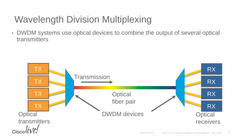
Wavelength Division Multiplexing
• DWDM systems use optical devices to combine the output of several optical transmitters
Optical
fiber pair
TX
Optical
transmittersOptical
receivers
TX
TX
TX
RX
RX
RX
RX
Transmission
DWDM devices
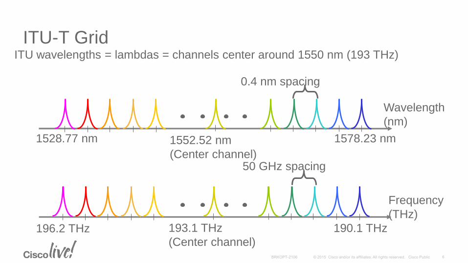
ITU-T Grid
Frequency
(THz)
Wavelength
(nm)
1528.77 nm 1578.23 nm
0.4 nm spacing
1552.52 nm
(Center channel)
196.2 THz 190.1 THz193.1 THz
(Center channel)
50 GHz spacing
ITU wavelengths = lambdas = channels center around 1550 nm (193 THz)
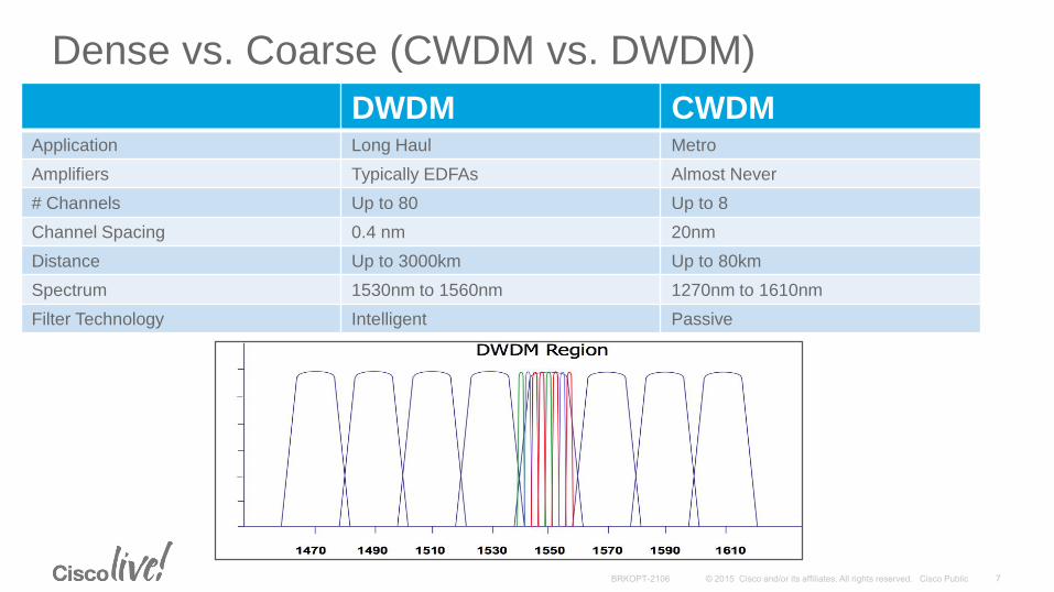
Dense vs. Coarse (CWDM vs. DWDM)
DWDM CWDMApplication Long Haul Metro
Amplifiers Typically EDFAs Almost Never
# Channels Up to 80 Up to 8
Channel Spacing 0.4 nm 20nm
Distance Up to 3000km Up to 80km
Spectrum 1530nm to 1560nm 1270nm to 1610nm
Filter Technology Intelligent Passive

Optical Fiber
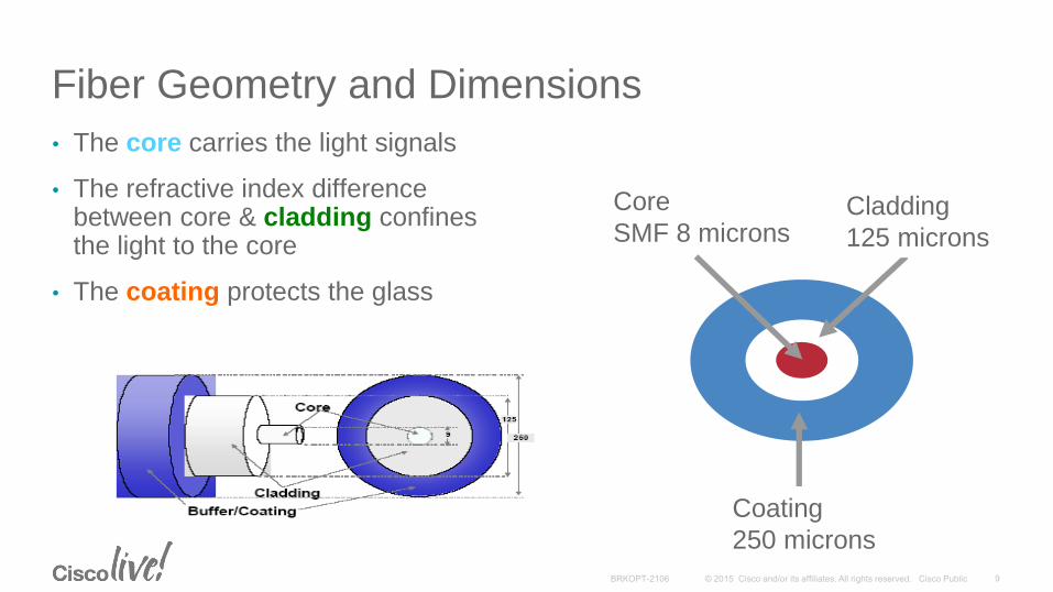
Fiber Geometry and Dimensions
• The core carries the light signals
• The refractive index difference between core & cladding confines the light to the core
• The coating protects the glass
Coating
250 microns
Cladding
125 microns
Core
SMF 8 microns
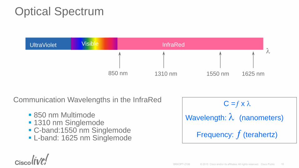
Communication Wavelengths in the InfraRed
850 nm Multimode 1310 nm Singlemode C-band:1550 nm Singlemode L-band: 1625 nm Singlemode
UltraViolet InfraRed
850 nm 1310 nm 1550 nm 1625 nm
l
Wavelength: l (nanometers)
Frequency: (terahertz)
C = x l
Visible
Optical Spectrum
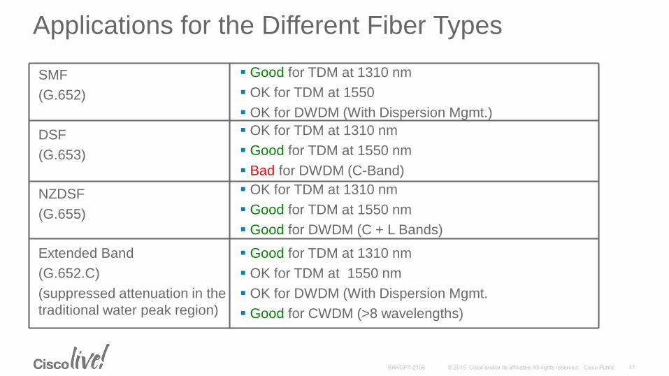
Good for TDM at 1310 nm
OK for TDM at 1550 nm
OK for DWDM (With Dispersion Mgmt.
Good for CWDM (>8 wavelengths)
Extended Band
(G.652.C)
(suppressed attenuation in the
traditional water peak region)
OK for TDM at 1310 nm
Good for TDM at 1550 nm
Good for DWDM (C + L Bands)
NZDSF
(G.655)
OK for TDM at 1310 nm
Good for TDM at 1550 nm
Bad for DWDM (C-Band)
DSF
(G.653)
Good for TDM at 1310 nm
OK for TDM at 1550
OK for DWDM (With Dispersion Mgmt.)
SMF
(G.652)
Applications for the Different Fiber Types

Linear Effects
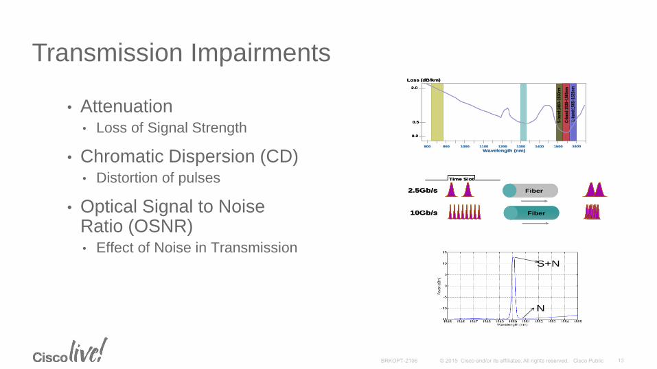
Transmission Impairments
• Attenuation• Loss of Signal Strength
• Chromatic Dispersion (CD)• Distortion of pulses
• Optical Signal to Noise Ratio (OSNR)• Effect of Noise in Transmission
800 900 1000 1100 1200 1300 1400 1500 1600
Wavelength (nm)
0.2
0.5
2.0
Loss (dB/km)
L-ba
nd:1
565–
1625
nm
C-b
and:
1530–1
565n
m
S-b
and:
1460–1
530n
m
800 900 1000 1100 1200 1300 1400 1500 1600
Wavelength (nm)
0.2
0.5
2.0
Loss (dB/km)
L-ba
nd:1
565–
1625
nm
C-b
and:
1530–1
565n
m
S-b
and:
1460–1
530n
m
Time Slot
10Gb/s
2.5Gb/s Fiber
Fiber
Time Slot
10Gb/s
2.5Gb/s Fiber
Fiber
S+N
N
S+N
N
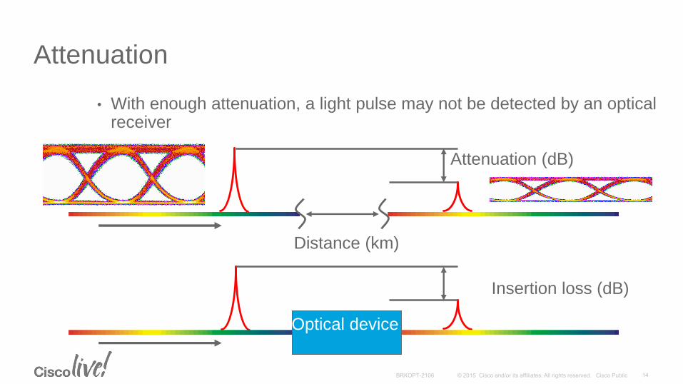
Attenuation
• With enough attenuation, a light pulse may not be detected by an optical receiver
Insertion loss (dB)
Attenuation (dB)
Distance (km)
Optical device
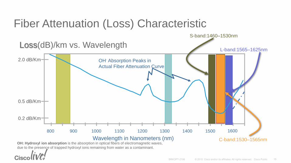
Fiber Attenuation (Loss) Characteristic
800 900 1000 1100 1200 1300 1400 1500 1600
OH- Absorption Peaks in
Actual Fiber Attenuation Curve
Wavelength in Nanometers (nm)
0.2 dB/Km
0.5 dB/Km
2.0 dB/Km
Loss(dB)/km vs. Wavelength
S-band:1460–1530nm
L-band:1565–1625nm
C-band:1530–1565nmOH: Hydroxyl ion absorption is the absorption in optical fibers of electromagnetic waves,
due to the presence of trapped hydroxyl ions remaining from water as a contaminant.
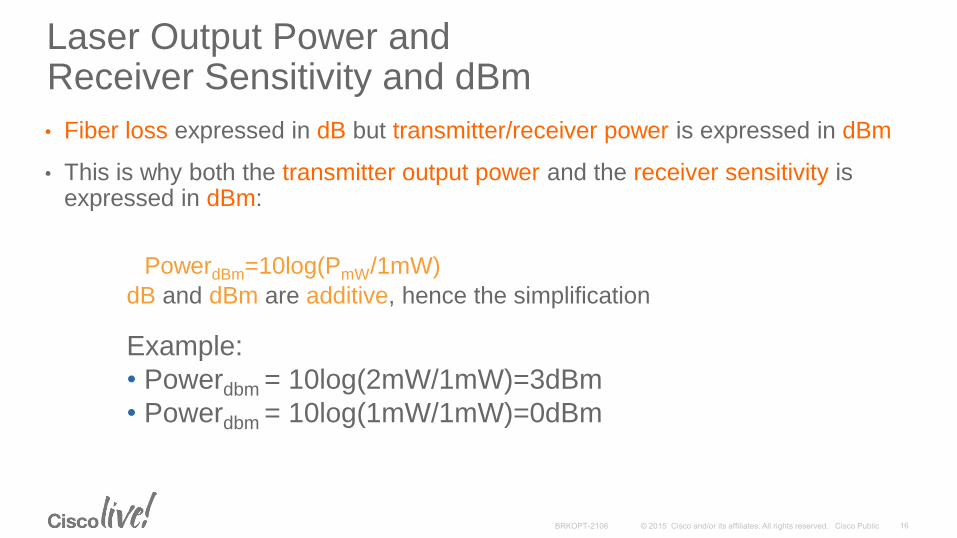
Laser Output Power and Receiver Sensitivity and dBm
• Fiber loss expressed in dB but transmitter/receiver power is expressed in dBm
• This is why both the transmitter output power and the receiver sensitivity is expressed in dBm:
PowerdBm=10log(PmW/1mW)
dB and dBm are additive, hence the simplification
Example:
• Powerdbm = 10log(2mW/1mW)=3dBm
• Powerdbm = 10log(1mW/1mW)=0dBm
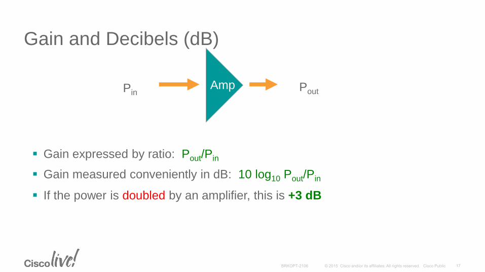
Gain expressed by ratio: Pout/Pin
Gain measured conveniently in dB: 10 log10 Pout/Pin
If the power is doubled by an amplifier, this is +3 dB
AmpPinPout
Gain and Decibels (dB)

Attenuation: Optical Budget
Optical Budget is affected by:• Fiber attenuation
• Splices
• Patch Panels/Connectors
• Optical components (filters, amplifiers, etc.)
• Bends in fiber
• Contamination (dirt/oil on connectors)
Basic Optical Budget = Tx Output Power – Rx Input Sensitivity
Pout = +6 dBm R = -30 dBm
Budget = 36 dB
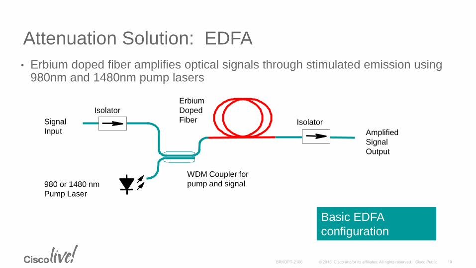
Signal
Input
980 or 1480 nm
Pump Laser
Erbium
Doped
Fiber
Amplified
Signal
Output
Isolator
WDM Coupler for
pump and signal
Isolator
Basic EDFA
configuration
Attenuation Solution: EDFA
• Erbium doped fiber amplifies optical signals through stimulated emission using 980nm and 1480nm pump lasers
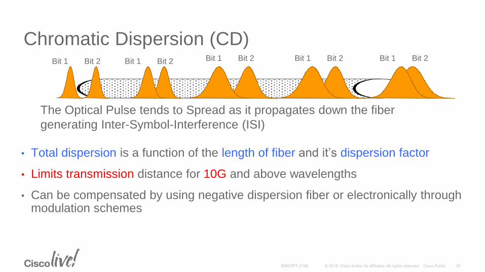
Chromatic Dispersion (CD)
• Total dispersion is a function of the length of fiber and it’s dispersion factor
• Limits transmission distance for 10G and above wavelengths
• Can be compensated by using negative dispersion fiber or electronically through modulation schemes
Bit 1 Bit 2 Bit 1 Bit 2Bit 1 Bit 2Bit 1 Bit 2 Bit 1 Bit 2
The Optical Pulse tends to Spread as it propagates down the fiber
generating Inter-Symbol-Interference (ISI)
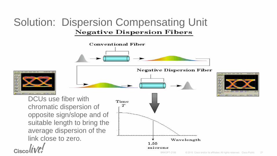
DCUs use fiber with chromatic dispersion of opposite sign/slope and of suitable length to bring the average dispersion of the link close to zero.
Solution: Dispersion Compensating Unit
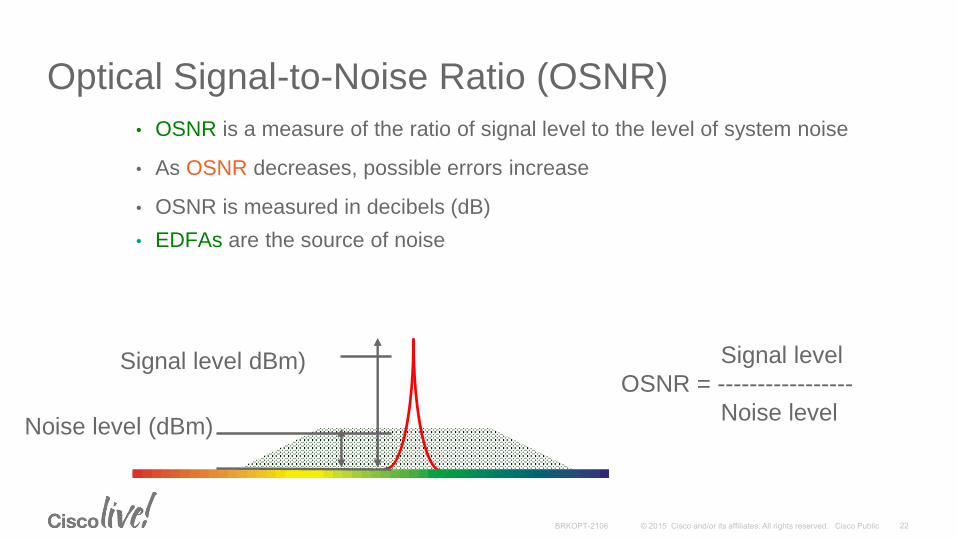
Optical Signal-to-Noise Ratio (OSNR)
• OSNR is a measure of the ratio of signal level to the level of system noise
• As OSNR decreases, possible errors increase
• OSNR is measured in decibels (dB)
• EDFAs are the source of noise
Signal level dBm)
Noise level (dBm)
Signal level
OSNR = -----------------
Noise level
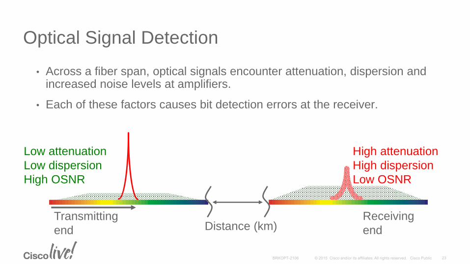
Optical Signal Detection
• Across a fiber span, optical signals encounter attenuation, dispersion and increased noise levels at amplifiers.
• Each of these factors causes bit detection errors at the receiver.
Distance (km)Transmitting
end
Receiving
end
Low attenuation
Low dispersion
High OSNR
High attenuation
High dispersion
Low OSNR
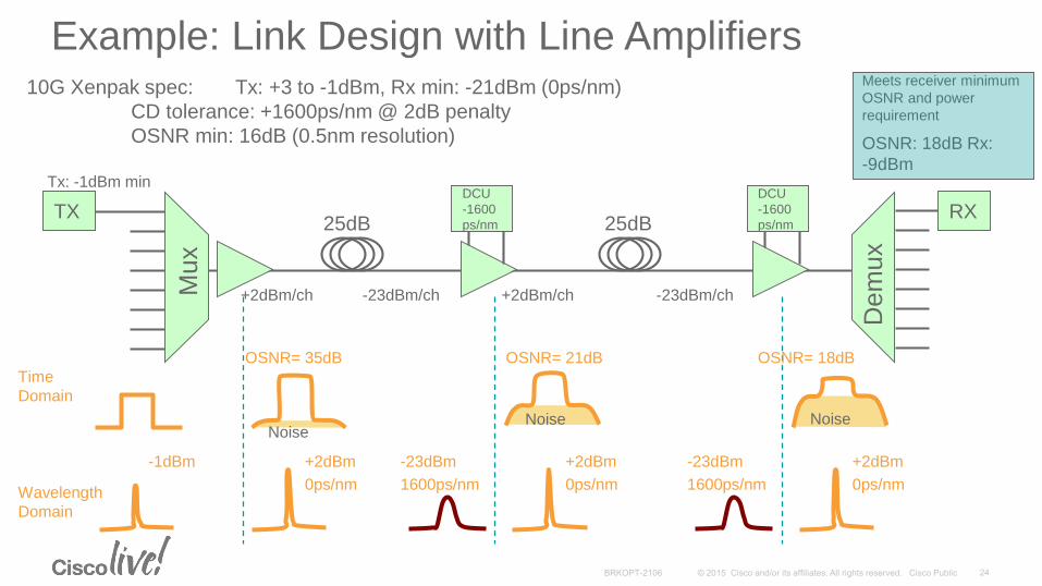
Example: Link Design with Line Amplifiers10G Xenpak spec: Tx: +3 to -1dBm, Rx min: -21dBm (0ps/nm)
CD tolerance: +1600ps/nm @ 2dB penalty
OSNR min: 16dB (0.5nm resolution)
-1dBm +2dBm
0ps/nm
Time
Domain
Wavelength
Domain
OSNR: 18dB Rx:
-9dBm
Meets receiver minimum
OSNR and power
requirement
+2dBm/ch
TX RX
Tx: -1dBm minM
ux
Dem
ux
DCU
-1600
ps/nm25dB 25dB
DCU
-1600
ps/nm
+2dBm/ch-23dBm/ch -23dBm/ch
OSNR= 21dB
Noise
OSNR= 18dB
Noise
OSNR= 35dB
Noise
-23dBm
1600ps/nm
+2dBm
0ps/nm
-23dBm
1600ps/nm
+2dBm
0ps/nm
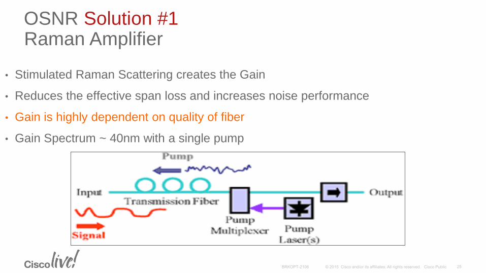
OSNR Solution #1Raman Amplifier
• Stimulated Raman Scattering creates the Gain
• Reduces the effective span loss and increases noise performance
• Gain is highly dependent on quality of fiber
• Gain Spectrum ~ 40nm with a single pump
Lo
g
(BE
R)
4 5 6 7 8 9 10 11 12 13 14 15–15
–14
–13
–12
–11
–10
–9
–8
–7
–6
–5
–4
–3
–2
–1
0
S/N (dB)
Uncoded
No FEC
G.709
RS(255,239)
Raw Channel BER=1.5e-3
EFEC=8.4 dBFEC=6.2 dB
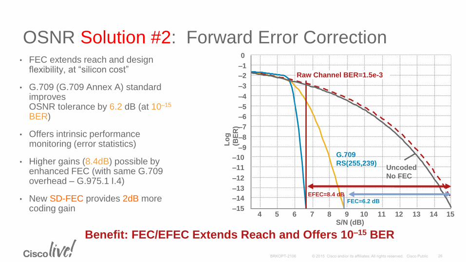
OSNR Solution #2: Forward Error Correction• FEC extends reach and design
flexibility, at “silicon cost”
• G.709 (G.709 Annex A) standard improves OSNR tolerance by 6.2 dB (at 10–15
BER)
• Offers intrinsic performance monitoring (error statistics)
• Higher gains (8.4dB) possible by enhanced FEC (with same G.709 overhead – G.975.1 I.4)
• New SD-FEC provides 2dB more coding gain
Benefit: FEC/EFEC Extends Reach and Offers 10–15 BER

Non-linear Effects
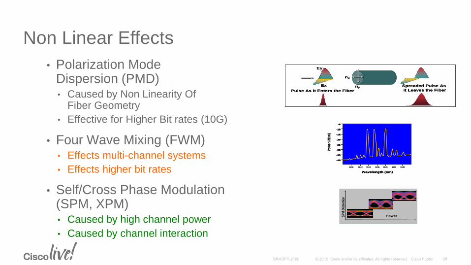
Non Linear Effects
• Polarization Mode Dispersion (PMD)• Caused by Non Linearity Of
Fiber Geometry
• Effective for Higher Bit rates (10G)
• Four Wave Mixing (FWM)• Effects multi-channel systems
• Effects higher bit rates
• Self/Cross Phase Modulation (SPM, XPM)• Caused by high channel power
• Caused by channel interaction
Wavelength (nm)
-5
-10
-15
-20
-25
-30
-35
-40
1542 1543 1544 1545 1546 1547 1548
Pow
er (d
Bm
)
Wavelength (nm)
-5
-10
-15
-20
-25
-30
-35
-40
1542 1543 1544 1545 1546 1547 1548
Wavelength (nm)
-5
-10
-15
-20
-25
-30
-35
-40
1542 1543 1544 1545 1546 1547 1548
Pow
er (d
Bm
)
nx
nyEx
Ey
Pulse As it Enters the Fiber
Spreaded Pulse As
it Leaves the Fiber
nx
nyEx
Ey
Pulse As it Enters the Fiber
Spreaded Pulse As
it Leaves the Fiber
Power SP
M D
isto
rtio
n
Power SP
M D
isto
rtio
n
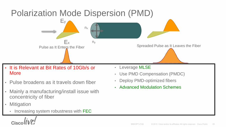
Polarization Mode Dispersion (PMD)
• It is Relevant at Bit Rates of 10Gb/s or More
• Pulse broadens as it travels down fiber
• Mainly a manufacturing/install issue with concentricity of fiber
• Mitigation
• Increasing system robustness with FEC
• Leverage MLSE
• Use PMD Compensation (PMDC)
• Deploy PMD-optimized fibers
• Advanced Modulation Schemes
nx
nyEx
Ey
Pulse as It Enters the Fiber Spreaded Pulse as It Leaves the Fiber

DWDM Components
Typical Components of DWDM Systems
• Optical transmitters and receivers
• DWDM mux/demux filters
• Optical add/drop multiplexers (OADMs)
• Reconfigurable OADM (ROADM)
• Optical amplifiers
• Transponders/Muxponders
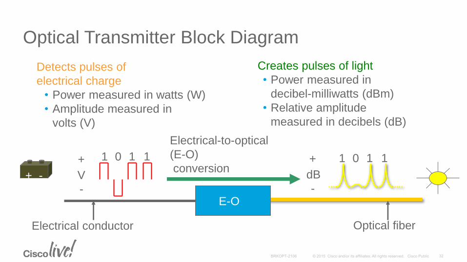
Optical Transmitter Block Diagram
Detects pulses of
electrical charge
• Power measured in watts (W)
• Amplitude measured in
volts (V)
Creates pulses of light
• Power measured in
decibel-milliwatts (dBm)
• Relative amplitude
measured in decibels (dB)
Electrical conductor
E-O
Optical fiber
1 11 01 11 0
Electrical-to-optical
(E-O)
conversion+
-
dB
+
-
V+ -
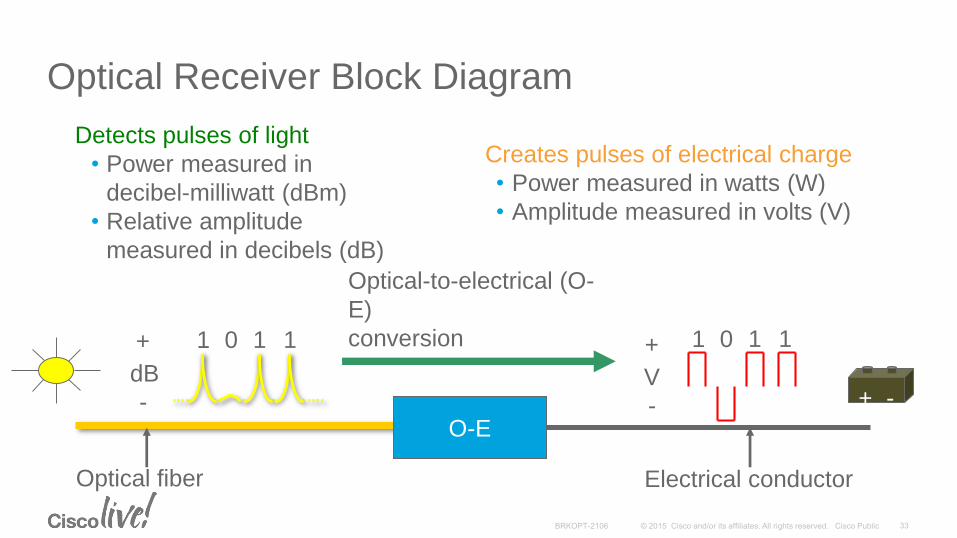
Optical Receiver Block Diagram
Detects pulses of light
• Power measured in
decibel-milliwatt (dBm)
• Relative amplitude
measured in decibels (dB)
Creates pulses of electrical charge
• Power measured in watts (W)
• Amplitude measured in volts (V)
Electrical conductor
O-E
Optical fiber
+ -
Optical-to-electrical (O-
E)
conversion1 11 0+
-
dB
1 11 0+
-
V
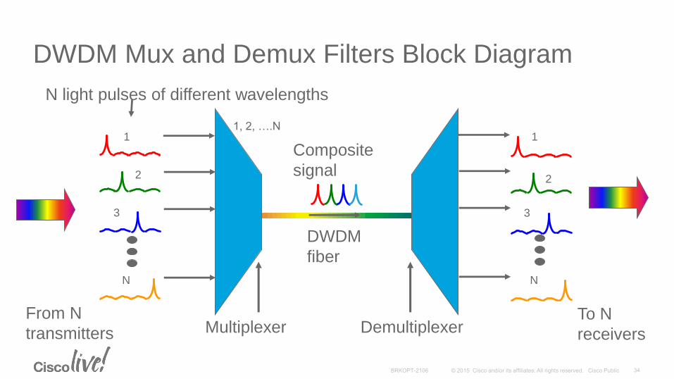
DWDM Mux and Demux Filters Block Diagram
1
2
3
N
DWDM
fiber
N light pulses of different wavelengths
From N
transmittersTo N
receivers
1
2
3
N
Composite
signal
Multiplexer Demultiplexer
1, 2, ….N
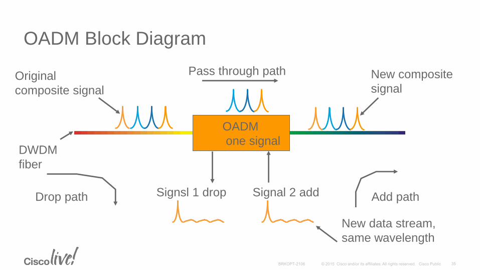
OADM Block Diagram
New data stream,
same wavelength
Signsl 1 drop
OADM
one signal
Pass through pathOriginal
composite signal
New composite
signal
Drop path Add path
DWDM
fiber
Signal 2 add
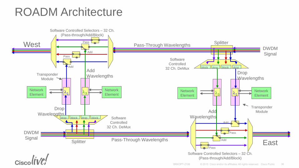
ROADM Architecture
Add
WavelengthsDrop
Wavelengths
Pass-Through WavelengthsSplitter
Add
WavelengthsSoftware
Controlled
32 Ch. DeMux
Pass-Through WavelengthsSplitter
l1Network
Elementl3
Network
Element
Software Controlled Selectors – 32 Ch.
(Pass-through/Add/Block)
DWDM
Signal
Transponder
Module
West
East
DWDM
Signal
Drop
Wavelengthsdrop block blockdrop
dropblock block drop
Software
Controlled
32 Ch. DeMux
Add
Pass
Add
Pass
Network
Element
Network
Element
Transponder
Module
Pass
Pass
Add
Add
Software Controlled Selectors – 32 Ch.
(Pass-through/Add/Block)
l1l3
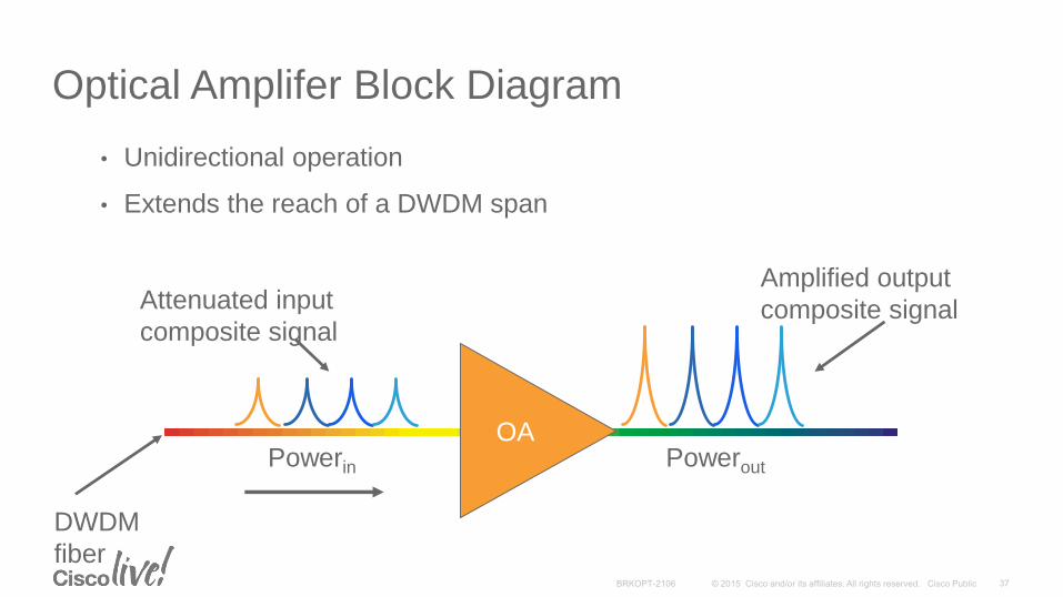
Optical Amplifer Block Diagram
• Unidirectional operation
• Extends the reach of a DWDM span
OA
DWDM
fiber
Attenuated input
composite signal
Amplified output
composite signal
Powerin Powerout
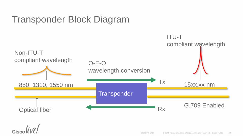
Transponder Block Diagram
Optical fiber
Non-ITU-T
compliant wavelength
ITU-T
compliant wavelength
O-E-O
wavelength conversion
850, 1310, 1550 nm 15xx.xx nm
Transponder
Tx
RxG.709 Enabled
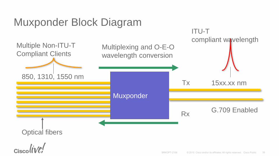
Muxponder Block Diagram
Optical fibers
Multiple Non-ITU-T
Compliant Clients
ITU-T
compliant wavelengthMultiplexing and O-E-O
wavelength conversion
850, 1310, 1550 nm15xx.xx nmTx
Rx
Muxponder
G.709 Enabled
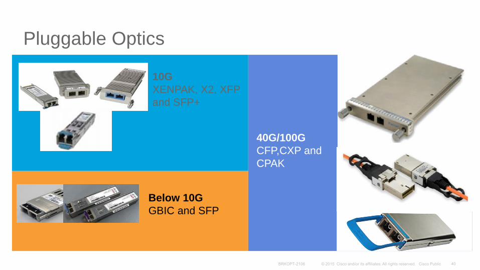
Pluggable Optics
10G
XENPAK, X2, XFP
and SFP+
Below 10G
GBIC and SFP
40G/100G
CFP,CXP and
CPAK
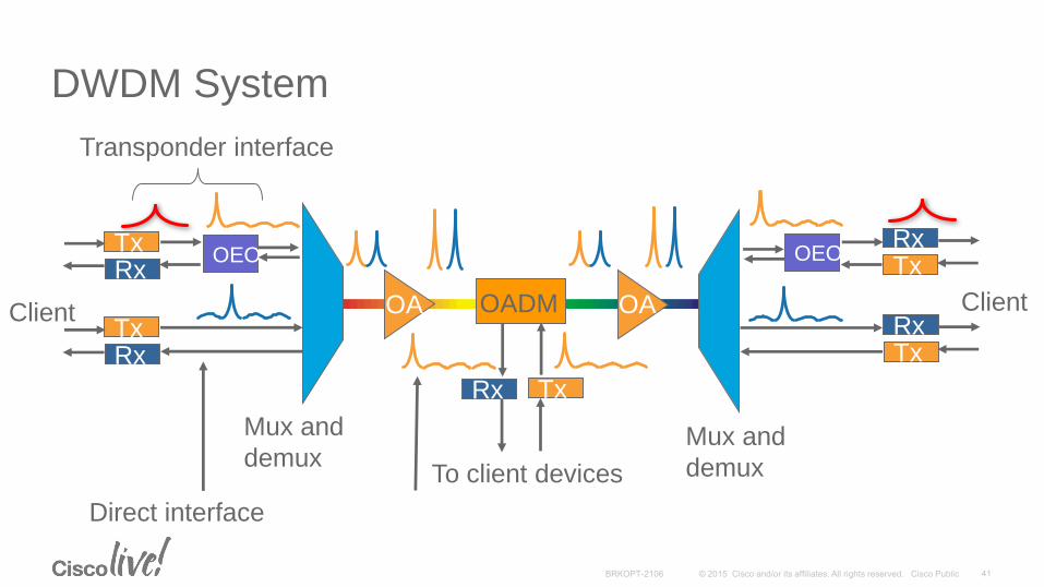
DWDM System
OEOTxRx
TxRx
OADM OAOA
Rx Tx
Transponder interface
OEOTxRx
TxRx
Direct interface
To client devices
ClientClient
Mux and
demuxMux and
demux

DWDM Software
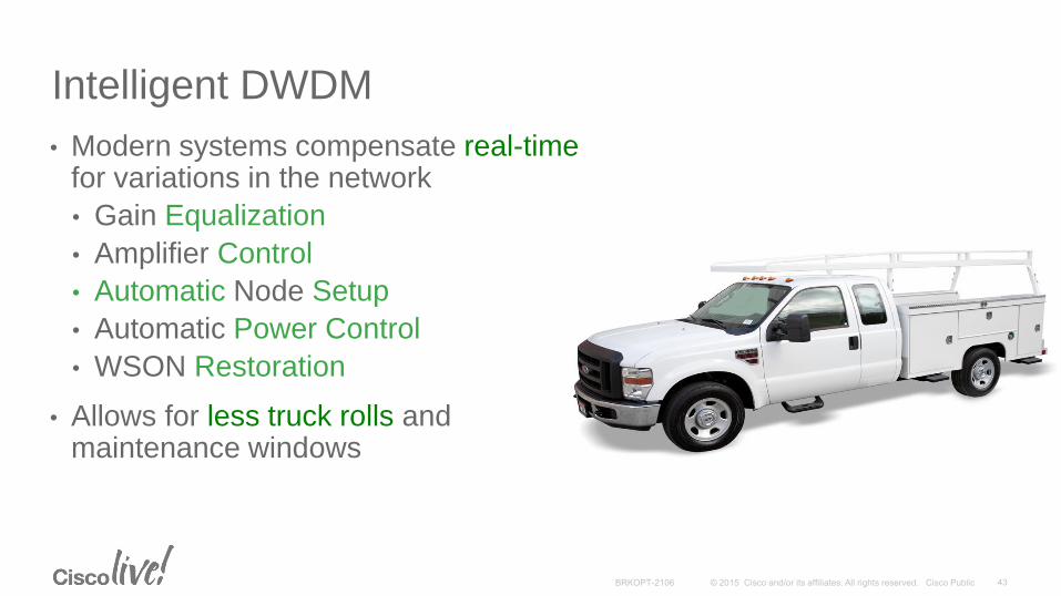
Intelligent DWDM
• Modern systems compensate real-time for variations in the network
• Gain Equalization
• Amplifier Control
• Automatic Node Setup
• Automatic Power Control
• WSON Restoration
• Allows for less truck rolls and maintenance windows
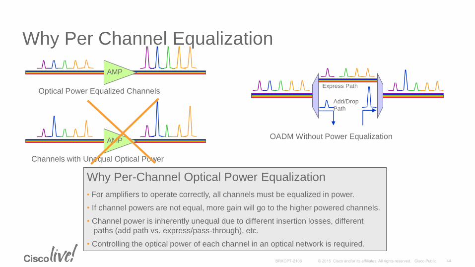
Why Per-Channel Optical Power Equalization
• For amplifiers to operate correctly, all channels must be equalized in power.
• If channel powers are not equal, more gain will go to the higher powered channels.
• Channel power is inherently unequal due to different insertion losses, different
paths (add path vs. express/pass-through), etc.
• Controlling the optical power of each channel in an optical network is required.
AMP
AMP
Optical Power Equalized Channels
Channels with Unequal Optical Power
OADM Without Power Equalization
Express Path
Add/Drop
Path
Why Per Channel Equalization
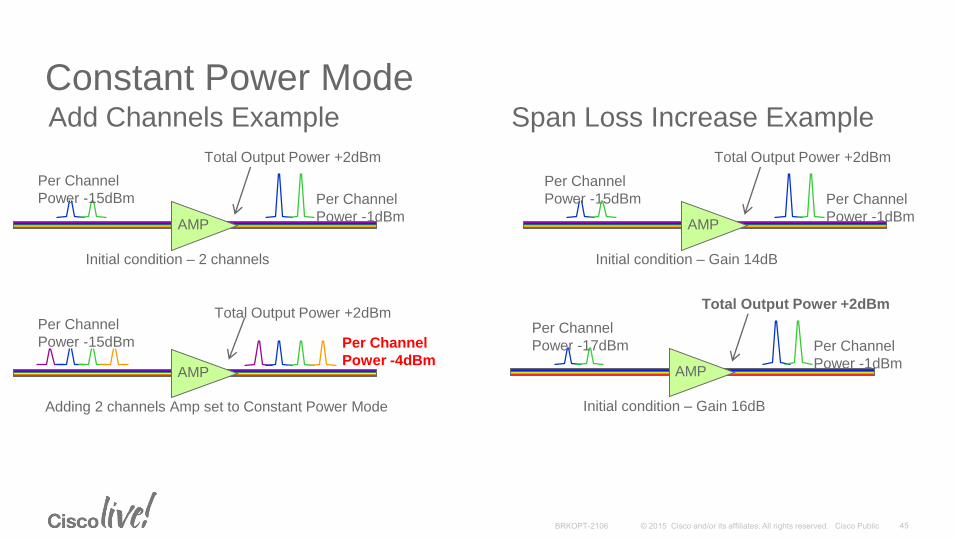
Constant Power Mode
AMP
Initial condition – 2 channels
Total Output Power +2dBm
Per Channel
Power -1dBm
AMP
Adding 2 channels Amp set to Constant Power Mode
Total Output Power +2dBm
Per Channel
Power -4dBm
Add Channels Example
AMP
Initial condition – Gain 14dB
Total Output Power +2dBm
Per Channel
Power -1dBm
Per Channel
Power -15dBm
AMP
Initial condition – Gain 16dB
Total Output Power +2dBm
Per Channel
Power -1dBm
Per Channel
Power -17dBm
Span Loss Increase Example
Per Channel
Power -15dBm
Per Channel
Power -15dBm
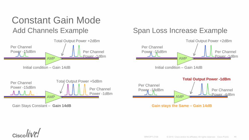
Constant Gain Mode
AMP
Initial condition – Gain 14dB
Total Output Power +2dBm
Per Channel
Power -1dBm
AMP
Gain Stays Constant – Gain 14dB
Total Output Power +5dBm
Per Channel
Power -1dBm
Add Channels Example
AMP
Initial condition – Gain 14dB
Total Output Power +2dBm
Per Channel
Power -1dBm
Per Channel
Power -15dBm
AMP
Gain stays the Same – Gain 14dB
Total Output Power -1dBm
Per Channel
Power -4dBm
Per Channel
Power -18dBm
Per Channel
Power -15dBm
Span Loss Increase Example
Per Channel
Power -15dBm
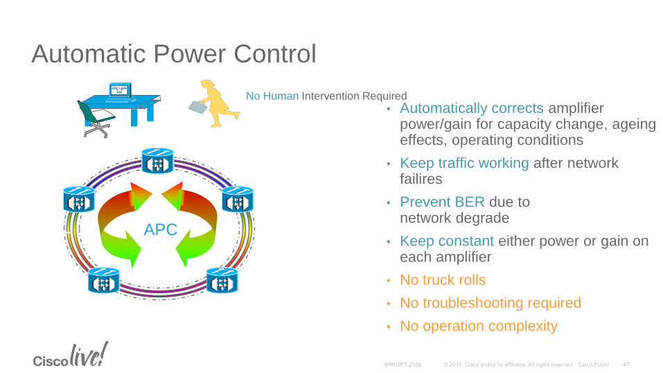
Automatic Power Control
• Automatically corrects amplifier power/gain for capacity change, ageing effects, operating conditions
• Keep traffic working after network failires
• Prevent BER due to network degrade
• Keep constant either power or gain on each amplifier
• No truck rolls
• No troubleshooting required
• No operation complexity
APC
No Human Intervention Required

Intro to OTN Switching
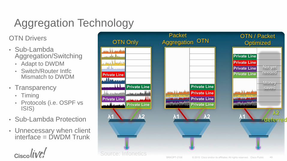
Aggregation Technology
OTN Drivers
• Sub-Lambda Aggregation/Switching• Adapt to DWDM
• Switch/Router IntfcMismatch to DWDM
• Transparency• Timing
• Protocols (i.e. OSPF vsISIS)
• Sub-Lambda Protection
• Unnecessary when client interface = DWDM Trunk
Source: Infonetics
OTN Only Packet
Aggregation OTN OTN / Packet
Optimized
Private Line
Private Line
Private Line
Private Line
Not yet needed
Money saved
λ2 λ1 λ2 λ1 λ2
deferred λ1
Private Line
Private Line
Private Line
Private Line
Private Line
Private Line
Private Line
Private Line
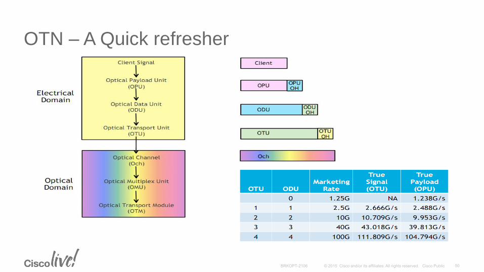
OTN – A Quick refresher
OPU
ODU
OTU OTU OTU
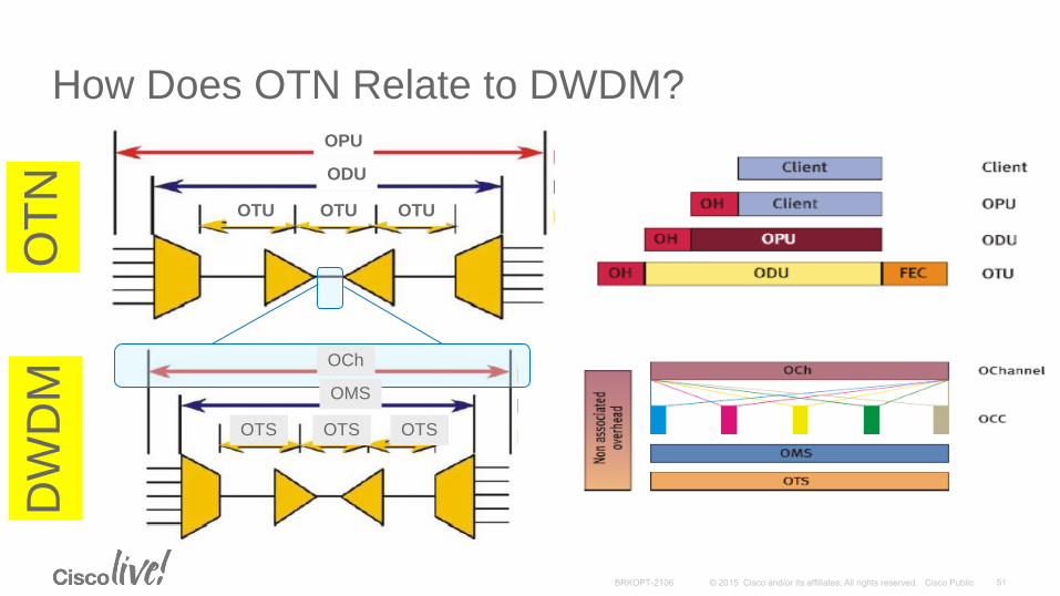
How Does OTN Relate to DWDM? O
TN
DW
DM
OCh
OMS
OTS OTS OTS
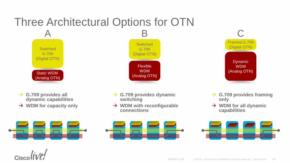
Three Architectural Options for OTN
Switched
G.709
(Digital OTN)
Static WDM
(Analog OTN)
Flexible
WDM
(Analog OTN)
Switched
G.709
(Digital OTN)
Dynamic
WDM
(Analog OTN)
Framed G.709
(Digital OTN)
A B C
G.709 provides all dynamic capabilities
WDM for capacity only
G.709 provides dynamic switching
WDM with reconfigurable connections
G.709 provides framing only
WDM for all dynamic capabilities
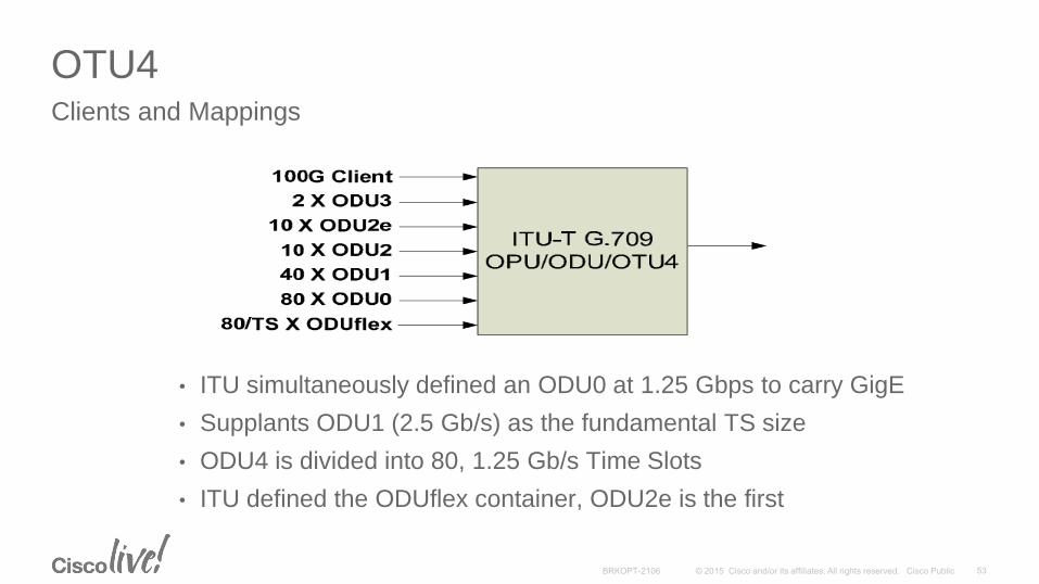
OTU4Clients and Mappings
• ITU simultaneously defined an ODU0 at 1.25 Gbps to carry GigE
• Supplants ODU1 (2.5 Gb/s) as the fundamental TS size
• ODU4 is divided into 80, 1.25 Gb/s Time Slots
• ITU defined the ODUflex container, ODU2e is the first

Increasing Capacity and Reach
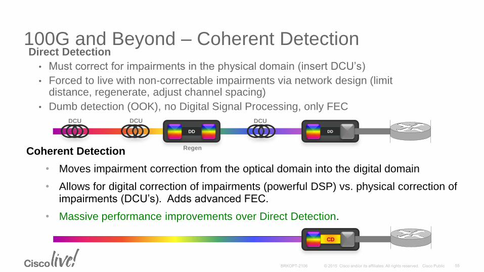
100G and Beyond – Coherent DetectionDirect Detection
• Must correct for impairments in the physical domain (insert DCU’s)
• Forced to live with non-correctable impairments via network design (limit distance, regenerate, adjust channel spacing)
• Dumb detection (OOK), no Digital Signal Processing, only FEC
Coherent Detection
• Moves impairment correction from the optical domain into the digital domain
• Allows for digital correction of impairments (powerful DSP) vs. physical correction of impairments (DCU’s). Adds advanced FEC.
• Massive performance improvements over Direct Detection.
DD
CD
DD
DCU DCU DCU
Regen
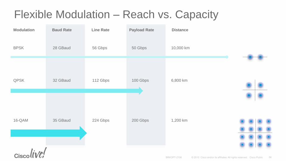
Flexible Modulation – Reach vs. Capacity
BPSK 28 GBaud 56 Gbps 50 Gbps 10,000 km
QPSK 32 GBaud 112 Gbps 100 Gbps 6,800 km
16-QAM 35 GBaud 224 Gbps 200 Gbps 1,200 km
Modulation Baud Rate Line Rate Payload Rate Distance
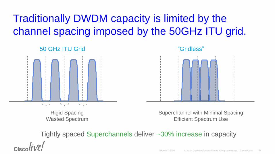
Traditionally DWDM capacity is limited by the
channel spacing imposed by the 50GHz ITU grid.
Rigid Spacing
Wasted Spectrum
Superchannel with Minimal Spacing
Efficient Spectrum Use
Tightly spaced Superchannels deliver ~30% increase in capacity
50 GHz ITU Grid “Gridless”

Adding Flexibility
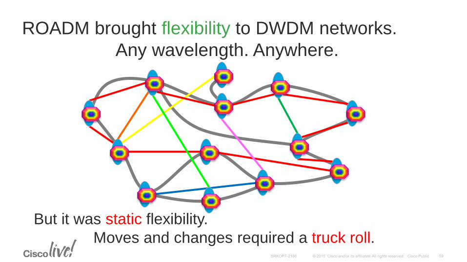
ROADM brought flexibility to DWDM networks.
Any wavelength. Anywhere.
But it was static flexibility.
Moves and changes required a truck roll.
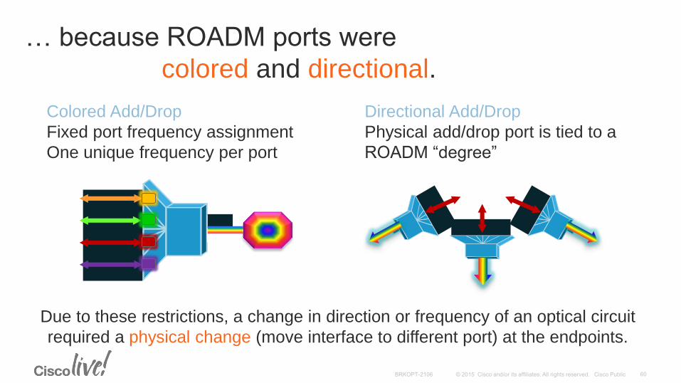
… because ROADM ports were
colored and directional.
Colored Add/Drop
Fixed port frequency assignment
One unique frequency per port
Directional Add/Drop
Physical add/drop port is tied to a
ROADM “degree”
Due to these restrictions, a change in direction or frequency of an optical circuit
required a physical change (move interface to different port) at the endpoints.
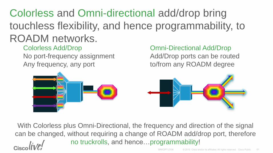
Colorless Add/Drop
No port-frequency assignment
Any frequency, any port
With Colorless plus Omni-Directional, the frequency and direction of the signal
can be changed, without requiring a change of ROADM add/drop port, therefore
no truckrolls, and hence…programmability!
Omni-Directional Add/Drop
Add/Drop ports can be routed
to/from any ROADM degree
Colorless and Omni-directional add/drop bring
touchless flexibility, and hence programmability, to
ROADM networks.
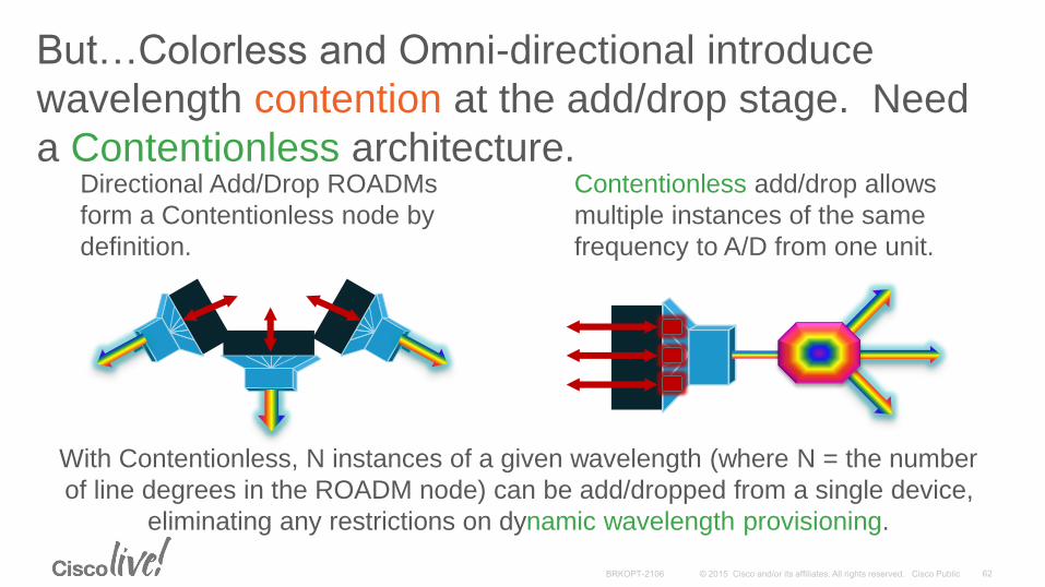
Directional Add/Drop ROADMs
form a Contentionless node by
definition.
With Contentionless, N instances of a given wavelength (where N = the number
of line degrees in the ROADM node) can be add/dropped from a single device,
eliminating any restrictions on dynamic wavelength provisioning.
Contentionless add/drop allows
multiple instances of the same
frequency to A/D from one unit.
But…Colorless and Omni-directional introduce
wavelength contention at the add/drop stage. Need
a Contentionless architecture.
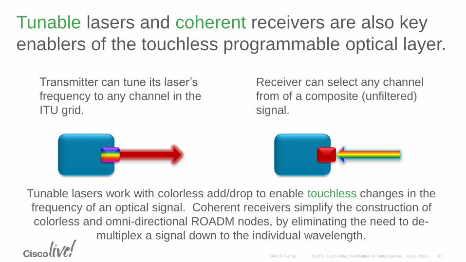
Transmitter can tune its laser’s
frequency to any channel in the
ITU grid.
Tunable lasers work with colorless add/drop to enable touchless changes in the
frequency of an optical signal. Coherent receivers simplify the construction of
colorless and omni-directional ROADM nodes, by eliminating the need to de-
multiplex a signal down to the individual wavelength.
Receiver can select any channel
from of a composite (unfiltered)
signal.
Tunable lasers and coherent receivers are also key
enablers of the touchless programmable optical layer.
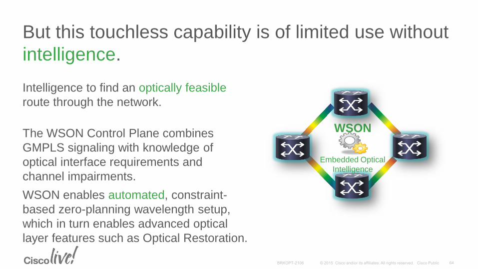
But this touchless capability is of limited use without
intelligence.
Intelligence to find an optically feasible
route through the network.
The WSON Control Plane combines
GMPLS signaling with knowledge of
optical interface requirements and
channel impairments.
WSON
Embedded Optical
Intelligence
WSON enables automated, constraint-
based zero-planning wavelength setup,
which in turn enables advanced optical
layer features such as Optical Restoration.
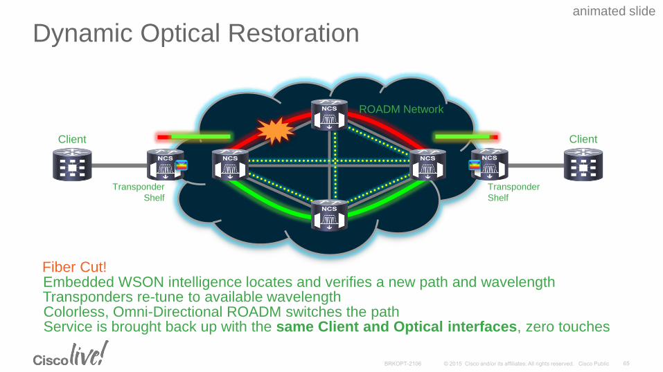
Dynamic Optical Restoration
Client
Colorless, Omni-Directional ROADM switches the pathService is brought back up with the same Client and Optical interfaces, zero touches
Embedded WSON intelligence locates and verifies a new path and wavelengthTransponders re-tune to available wavelength
Fiber Cut!
animated slide
Client
ROADM Network
Transponder
Shelf
Transponder
Shelf
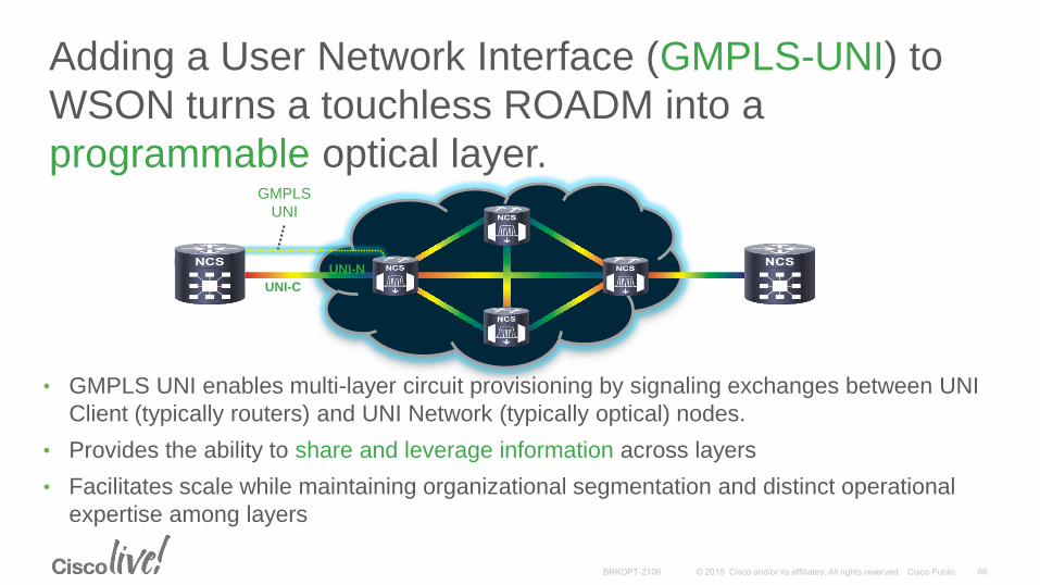
Adding a User Network Interface (GMPLS-UNI) to
WSON turns a touchless ROADM into a
programmable optical layer.
• GMPLS UNI enables multi-layer circuit provisioning by signaling exchanges between UNI
Client (typically routers) and UNI Network (typically optical) nodes.
• Provides the ability to share and leverage information across layers
• Facilitates scale while maintaining organizational segmentation and distinct operational
expertise among layers
UNI-C
UNI-N
GMPLS
UNI
Key Takeaways
• Dramatic increase in Bandwidth has led to the use of DWDM
• Fiber type effects the quality of transmission
• Linear Effects are predictable and can be compensated
• Non-Linear Effects are known but somewhat unpredictable
• OTN Switching is an emerging transport technology
• Modern DWDM systems are intelligent and simple to operate
• Good reference is: http://www.cisco.com/en/US/products/hw/optical/ps2011/products_technical_reference_chapter09186a00802342dd.html
Introduction – What is DWDM?
Optical Fiber
Linear/Non-linear Effects and Solutions
DWDM Components
DWDM Software
Intro to OTN
Increasing Capacity, Flexibility and Reach in DWDM
Conclusion

Complete Your Online Session Evaluation
Don’t forget: Cisco Live sessions will be available for viewing on-demand after the event at CiscoLive.com/Online
• Give us your feedback to be entered into a Daily Survey Drawing. A daily winner will receive a $750 Amazon gift card.
• Complete your session surveys though the Cisco Live mobile app or your computer on Cisco Live Connect.

Continue Your Education
• Demos in the Cisco Campus
• Walk-in Self-Paced Labs
• Table Topics
• Meet the Engineer 1:1 meetings

Thank you
Glossary Arrayed Waveguide (AWG)
Automatic Node Setup (ANS)
Automatic Power Control (APC)
Chromatic Dispersion (CD)
Cross Phase Modulation (XPM)
Decibels (dB)
Decibels-milliwatt (dBm)
Dense Wavelength Division Multiplexing (DWDM)
Dispersion Compensation Unit (DCU)
Dispersion Shifted Fiber (DSF)
Erbium Doped Fiber Amplifier (EDFA)
Four-Wave Mixing (FWM)
GlossaryInternational Telecommunications Union (ITU)
Non-Zero Dispersion Shifted Fiber (NZ-DSF)
Optical Add Drop Multiplexer (OADM)
Optical Signal to Noise Ratio (OSNR)
Optical Supervisory Channel (OSC)
Optical Supervisory Channel Module (OSCM)
Polarization Mode Dispersion (PMD)
Reconfigurable Optical Add Drop Multiplexer (ROADM)
Self Phase Modulation (SPM)
Single Mode Fiber (SMF)
Variable Optical Attenuator (VOA)