Embed Size (px)
DESCRIPTION
DWDM Hardware description in detail
Citation preview
HARDWARE DESCRIPTION DETAIL OF DWDM(10G)
HARDWARE DESCRIPTION DETAIL OF DWDM(10G)
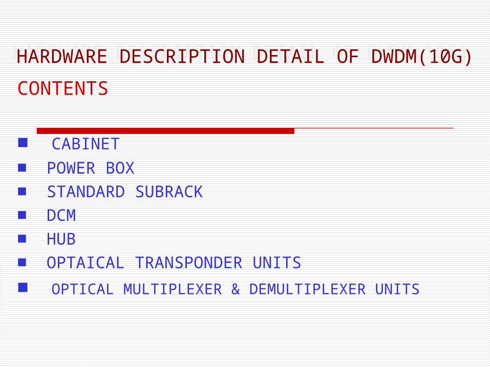
CONTENTS
■ CABINET
■ POWER BOX■ STANDARD SUBRACK■ DCM■ HUB ■ OPTAICAL TRANSPONDER UNITS
■ OPTICAL MULTIPLEXER & DEMULTIPLEXER UNITS
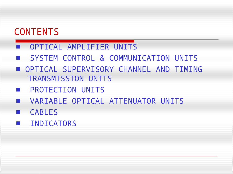
CONTENTS ■ OPTICAL AMPLIFIER UNITS■ SYSTEM CONTROL & COMMUNICATION UNITS■ OPTICAL SUPERVISORY CHANNEL AND TIMING
TRANSMISSION UNITS■ PROTECTION UNITS■ VARIABLE OPTICAL ATTENUATOR UNITS■ CABLES■ INDICATORS
CABINET
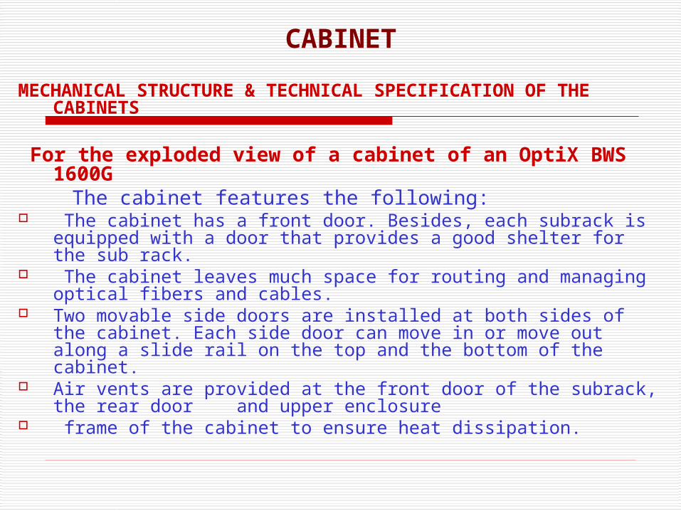
MECHANICAL STRUCTURE & TECHNICAL SPECIFICATION OF THE CABINETS
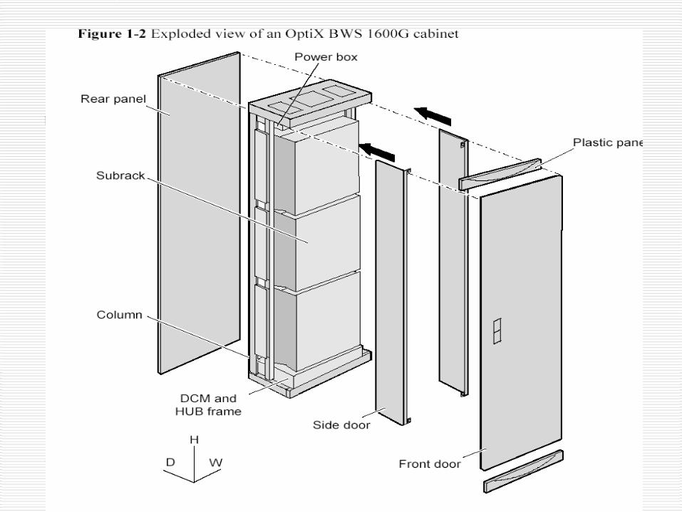
For the exploded view of a cabinet of an OptiX BWS
1600G The cabinet features the following: The cabinet has a front door. Besides, each subrack is equipped with a
door that provides a good shelter for the sub rack. The cabinet leaves much space for routing and managing optical fibers and
cables. Two movable side doors are installed at both sides of the cabinet. Each side
door can move in or move out along a slide rail on the top and the bottom of the cabinet.
Air vents are provided at the front door of the subrack, the rear door and upper enclosure
frame of the cabinet to ensure heat dissipation.
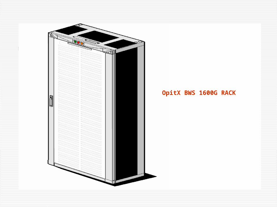
OpitX BWS 1600G RACK
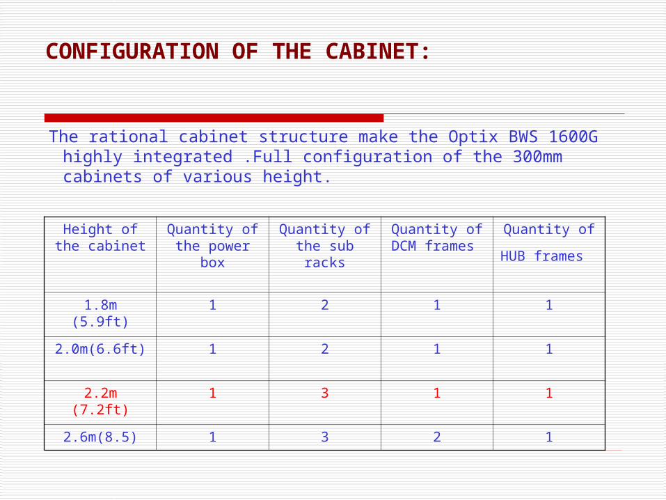
The rational cabinet structure make the Optix BWS 1600G highly integrated .Full configuration of the 300mm cabinets of various height.
Height of the cabinet
Quantity of the power
box
Quantity of the sub racks
Quantity of DCM frames
Quantity of
HUB frames
1.8m (5.9ft) 1 2 1 1
2.0m(6.6ft) 1 2 1 1
2.2m (7.2ft) 1 3 1 1
2.6m(8.5) 1 3 2 1
CONFIGURATION OF THE CABINET:
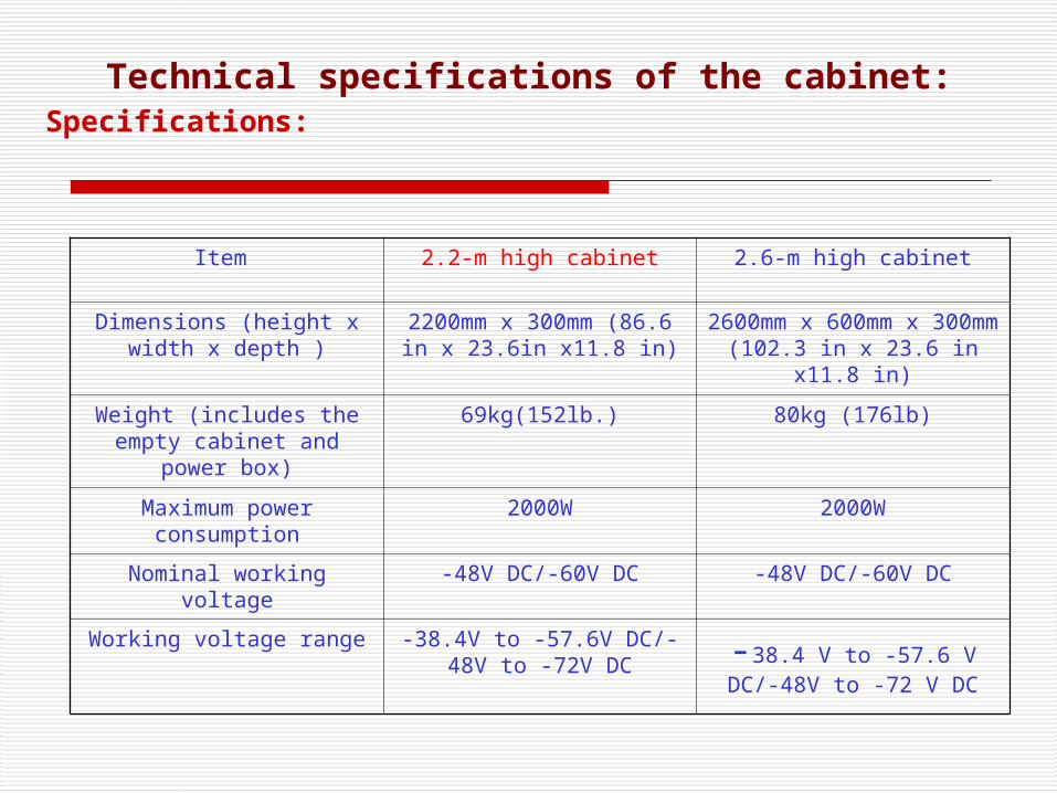
Technical specifications of the cabinet:Specifications:
Item 2.2-m high cabinet 2.6-m high cabinet
Dimensions (height x width x depth )
2200mm x 300mm (86.6 in x 23.6in x11.8 in)
2600mm x 600mm x 300mm (102.3 in x 23.6
in x11.8 in)
Weight (includes the empty cabinet and power
box)
69kg(152lb.) 80kg (176lb)
Maximum power consumption
2000W 2000W
Nominal working voltage -48V DC/-60V DC -48V DC/-60V DC
Working voltage range -38.4V to -57.6V DC/-48V to -72V DC -38.4 V to -57.6 V DC/-
48V to -72 V DC
POWER BOX
A power box for the Optix BWS 1600G is mounted at the top of the cabinet . A pluggable lightning protection devices is adopted, easy for operation & maintenance. The power box provides the standard -48 V DC or -60 V DC to the cabinet. it is closed structure with all user interfaces placed on its front panel.
A PMU Board is the main part of the Power Box. The board has the following functions:
A power box mainly used to access two independent -48 V DC inputs or two independent -60 V DC inputs. It distributes reliable power supply to the unit of the equipment.
Provides low voltage protection. Control Cabinet indicators and SCC communication. Generating ringing current: The board provides ringing current for
Order wire . Monitoring ringing Current: The board test whether the ringing
currents for Order wire is normal and reports the alarms information such as Invalid ringing current.
Monitoring Voltage: A PMU Monitors the input voltage of two -48 V/-60V Power. the PMU also reports the voltage value and voltage alarms.
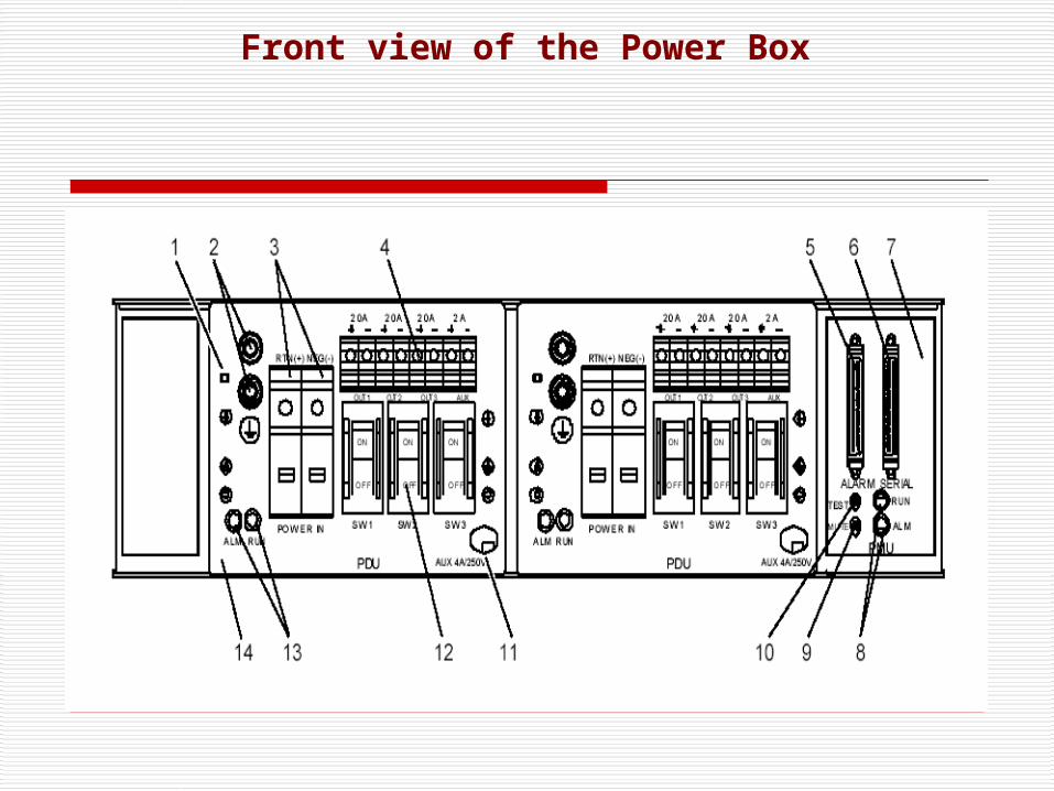
Front view of the Power Box
1. Grounding mode indication hole: it indicates the grounding mode when the copper wire is connecting to the indication hole, the DC-1 grounding mode is adapted.
2. Protection grounding screw of the PDU: it connect with the protection grounding PGND cable.
3. Power input terminal:NEG(-) connects with -48V/-60V power cable and RTN (+) connects with the reflow grounding cable.
4. Power output terminal:OTU1/OTU2/OTU3 supply power to sub rack and each channel is 20A. AUX supplies power for HUB which is 2A.
5. Alarm interface: it is for alarm input and cascade.6. Serial interface: it for communication between PMU and Sub rack.7. PMU: It is a power monitoring unit.8. RUN indicator (green) and ALM indicator (red) on the PMU: it indicates the
running states of the PMU. 9. Alarm elimination Switch mute): it for eliminating the audio able alarm. It is in
the ON state usually. When it is in the OFF state no alarm audible is generated whether there is any critical alarm.
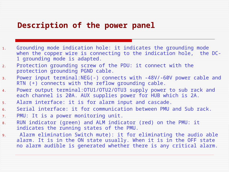
Description of the power panel
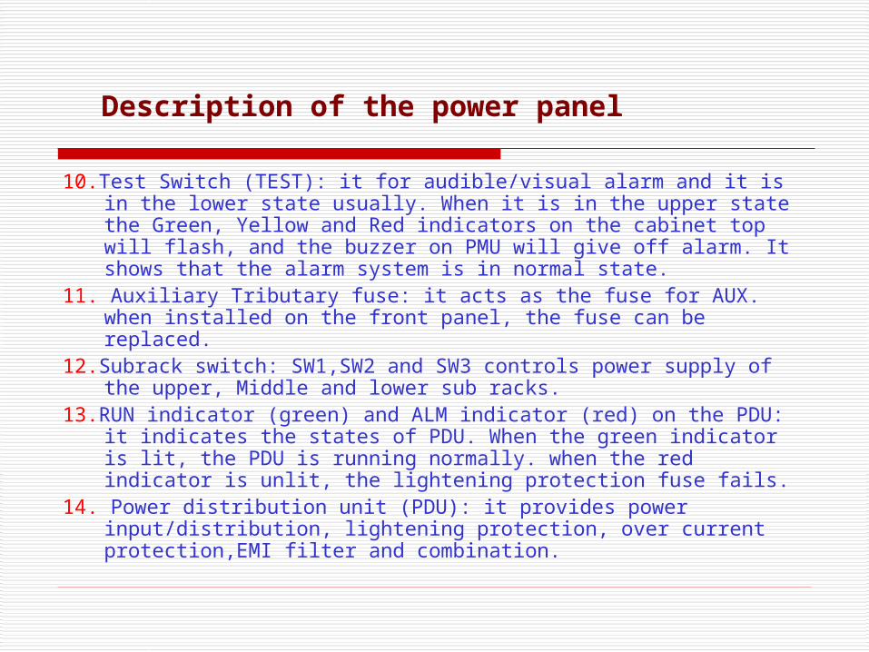
10.Test Switch (TEST): it for audible/visual alarm and it is in the lower state usually. When it is in the upper state the Green, Yellow and Red indicators on the cabinet top will flash, and the buzzer on PMU will give off alarm. It shows that the alarm system is in normal state.
11. Auxiliary Tributary fuse: it acts as the fuse for AUX. when installed on the front panel, the fuse can be replaced.
12.Subrack switch: SW1,SW2 and SW3 controls power supply of the upper, Middle and lower sub racks.
13.RUN indicator (green) and ALM indicator (red) on the PDU: it indicates the states of PDU. When the green indicator is lit, the PDU is running normally. when the red indicator is unlit, the lightening protection fuse fails.
14. Power distribution unit (PDU): it provides power input/distribution, lightening protection, over current protection,EMI filter and combination.
Description of the power panel
STANDARD SUBRACK
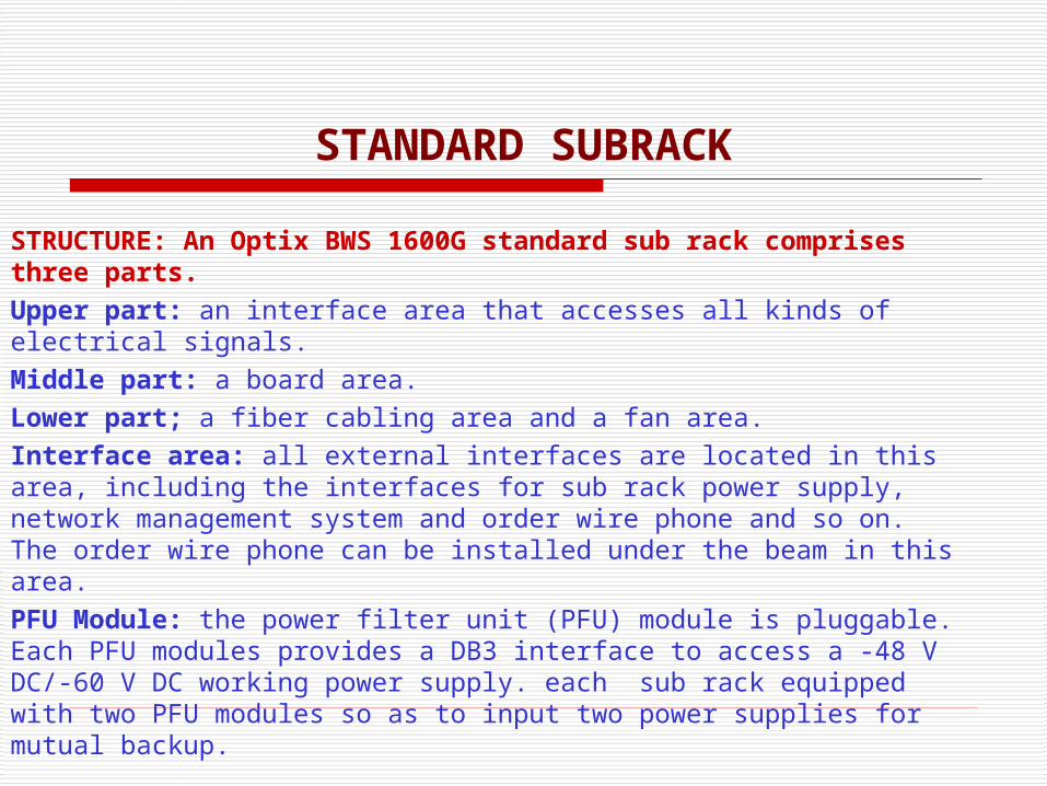
STRUCTURE: An Optix BWS 1600G standard sub rack comprises three parts.Upper part: an interface area that accesses all kinds of electrical signals.Middle part: a board area.Lower part; a fiber cabling area and a fan area.Interface area: all external interfaces are located in this area, including the interfaces for sub rack power supply, network management system and order wire phone and so on. The order wire phone can be installed under the beam in this area.PFU Module: the power filter unit (PFU) module is pluggable. Each PFU modules provides a DB3 interface to access a -48 V DC/-60 V DC working power supply. each sub rack equipped with two PFU modules so as to input two power supplies for mutual backup.
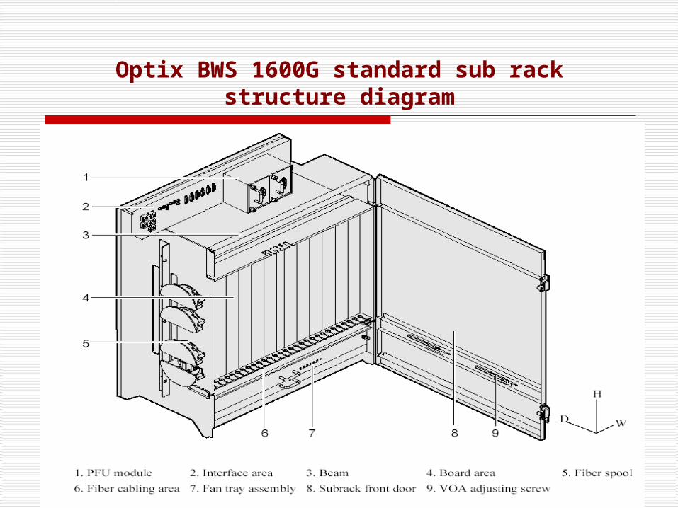
Optix BWS 1600G standard sub rack structure diagram
Sub rack Detail
Board area: Totally 13 slots are available,IU1,IU2,IU3…..IU13 from left to right when you face the front surface of the sub rack. Slot IU7 is for SCC board and is 24mm (0.9-inch) wide. Other slots are 38-mm (1.5-inch) wide. Fiber cabling area: all the optical fiber from the optical interfaces are routed to this area these optical fibers then came out of this area and reach the matched side of the subrack.there are fiber spool at the two sides of the sub rack. these spools allow good management over the optical fibers. mechanical variable optical attenuator (VOA) is installed here.
FAN TRAY ASSEMBLY:
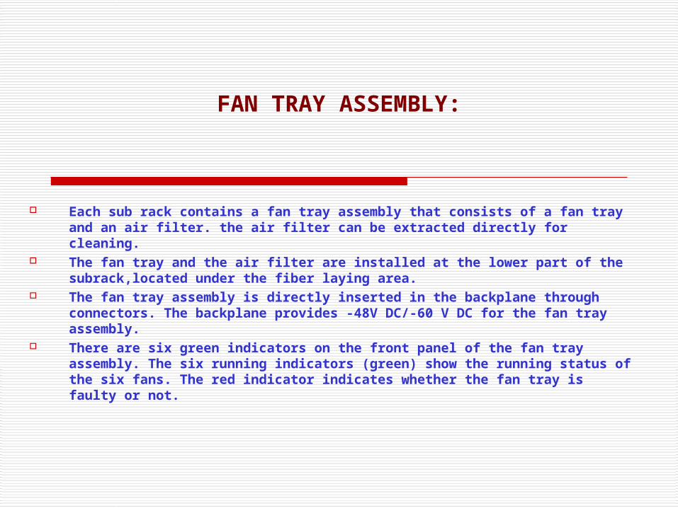
Each sub rack contains a fan tray assembly that consists of a fan tray and an air filter. the air filter can be extracted directly for cleaning.
The fan tray and the air filter are installed at the lower part of the subrack,located under the fiber laying area.
The fan tray assembly is directly inserted in the backplane through connectors. The backplane provides -48V DC/-60 V DC for the fan tray assembly.
There are six green indicators on the front panel of the fan tray assembly. The six running indicators (green) show the running status of the six fans. The red indicator indicates whether the fan tray is faulty or not.
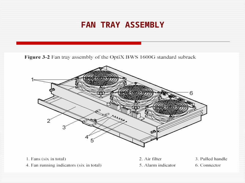
FAN TRAY ASSEMBLY
COMMUNICATION & MAINTANCE INTERFACES
The Optix BWS 1600G standard sub rack provides rich interfaces for communication and maintenance.
Interface in the interface area
The interface provides functional interfaces such as management interface, communication interface and alarm output interface.
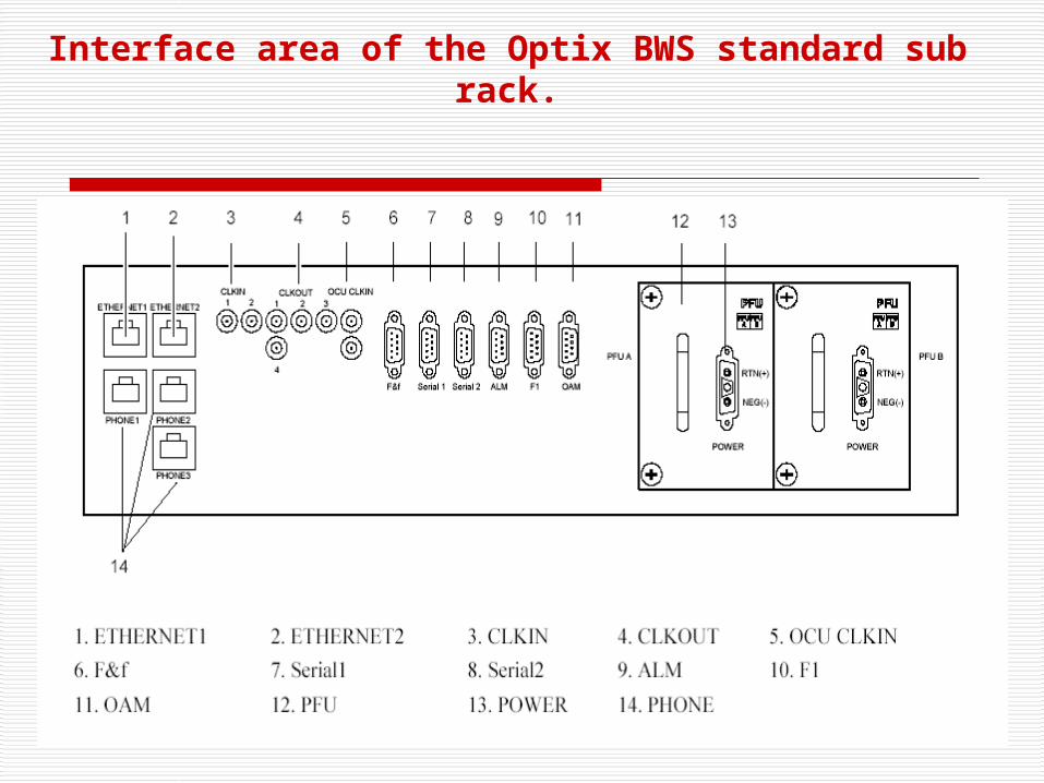
Interface area of the Optix BWS standard sub rack.
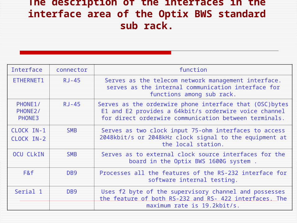
The description of the interfaces in the interface area of the Optix BWS standard sub
rack.
Interface connector function
ETHERNET1 RJ-45 Serves as the telecom network management interface. serves as the internal communication interface for functions among sub
rack.
PHONE1/PHONE2/PHONE3
RJ-45 Serves as the orderwire phone interface that (OSC)bytes E1 and E2 provides a 64kbit/s orderwire voice channel for direct
orderwire communication between terminals.
CLOCK IN-1CLOCK IN-2
SMB Serves as two clock input 75-ohm interfaces to access 2048kbit/s or 2048kHz clock signal to the equipment at the local station.
OCU CLkIN SMB Serves as to external clock source interfaces for the board in the Optix BWS 1600G system .
F&f DB9 Processes all the features of the RS-232 interface for software internal testing.
Serial 1 DB9 Uses f2 byte of the supervisory channel and possesses the feature of both RS-232 and RS- 422 interfaces. The maximum
rate is 19.2kbit/s.
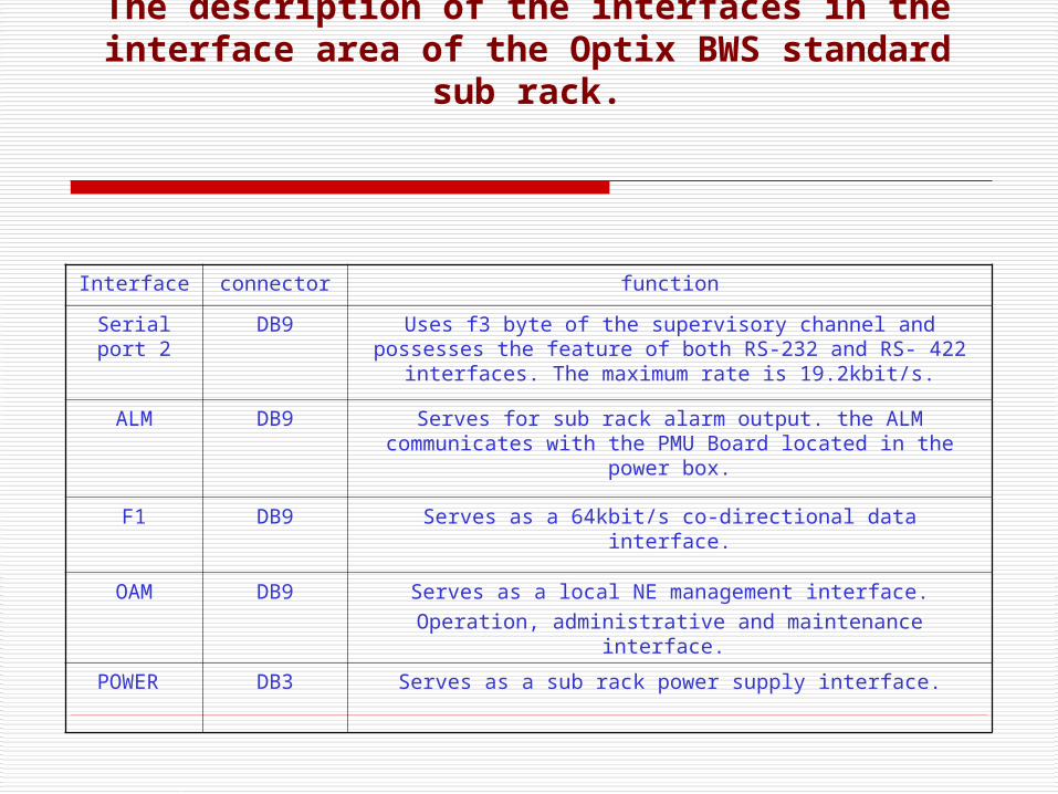
The description of the interfaces in the interface area of the Optix BWS standard sub
rack.
Interface connector function
Serial port 2
DB9 Uses f3 byte of the supervisory channel and possesses the feature of both RS-232 and RS- 422 interfaces. The
maximum rate is 19.2kbit/s.
ALM DB9 Serves for sub rack alarm output. the ALM communicates with the PMU Board located in the power box.
F1 DB9 Serves as a 64kbit/s co-directional data interface.
OAM DB9 Serves as a local NE management interface.Operation, administrative and maintenance interface.
POWER DB3 Serves as a sub rack power supply interface.
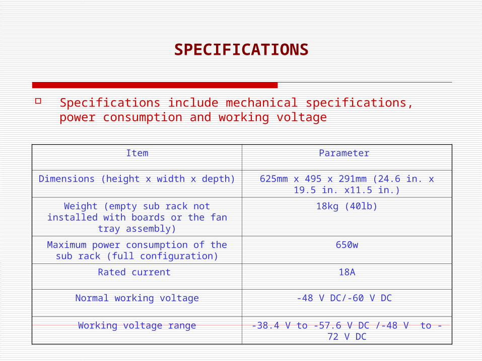
SPECIFICATIONS
Specifications include mechanical specifications, power consumption and working voltage
Item Parameter
Dimensions (height x width x depth) 625mm x 495 x 291mm (24.6 in. x 19.5 in. x11.5 in.)
Weight (empty sub rack not installed with boards or the fan tray assembly)
18kg (40lb)
Maximum power consumption of the sub rack (full configuration)
650w
Rated current 18A
Normal working voltage -48 V DC/-60 V DC
Working voltage range -38.4 V to -57.6 V DC /-48 V to -72 V DC
DCM Module
A DCM (DISPERSION COMPENSATION MODULE) can be installed on an optical amplifier unit at the transmit end or the receiver end according to the actual situation.A DCM is located in a DCM frame that is in the lowest position of the cabinet.
after the optical signal is transmitted over a certain distance, the accumulation of positive dispersion widens the optical signal pulse. This seriously affects the system transmission performance. To minimize such an effects, a passive DCM is used in the network.
A DCM used negative dispersion to compensate for the positive dispersion of a transmitting fiber,So as to keep the original shape of the signal pulse.

Appearance of a DCM
Module Dimensions (Height x width x Depth Weight
DCM 44mm x238mm (1.7 in. x 9.4 in. x 10.5 in.) 3.5kg (7.7lb)
Dimensions and weight of a DCM

HUB
A HUB is required in a station with multiple sub racks. The HUB ports connect with the network port in the interface area of every sub rack through network cables. This realize the communication between the sub rack. A HUB is powered by a power box on the top of a cabinet where the HUB and power Box locate. Dimensions and weight of HUB:
HUB Frame:A HUB frame comprises two parts: a box body and a HUB tray.A HUB is located in a HUB frame that is in the lowest position of the cabinet. the HUB frame right under the DCM frame .At most two Hubs can be placed in to one HUB frame.
Module Dimensions (height x width x Depth
Weight
HUB 34mm x 110mm x 150mm (1.3 in. x 34.3 in x5.9
0.30kg (0.66lb)

OPTICAL TRANSPONDERS UNIT(OTU)
DESCRIPTION OF THE TRANSPONDERS: 1. LWF (STM-64 transmit-receive line wavelength conversion unit with
FEC function)2. LWF WAN(10GE transmit-receive line wavelength conversion unit
with FEC function)3. TMX (4-channel STM-16 asynchronous MUX OTU-2 wavelength
conversion board)4. LOG (8-port Gigabit Ethernet multiplex optical wavelength
conversion board)

LWF (STM-64 transmit-receive line wavelength conversion unit with FEC function)
Application :The LWF is type of optical transponder unit. The LWF realizes the conversion between STM-64 optical signals and ITU-T Recommendation –complaint WDM.
Working principle and signal flow: The LWF unit consists of five parts: the client –side
optical module, the WDM-side optical module, the service enable/disable –capsulation and processing module, the control and communication module, and the power supply module.

The functional block diagram of LWF STM-64 unit

LWF (10GE-WAN transmit-receive line wavelength conversion unit with FEC function)
Application :The LWF (WAN) is type of optical transponder unit. The LWF realizes the conversion between 10GE-WAN optical signals and ITU-T Recommendation –complaint WDM.
Working principle and signal flow: The LWF (WAN) unit consists of five parts: the client –side optical
module, the WDM-side optical module, the service enable/disable –capsulation and processing module, the control and communication module, and the power supply module.

The functional block diagram of LWF 10GE-WAN unit

ETMX (4-channel STM-16 asynchronous MUX OUT-2 wavelength conversion board)
Application :The TMX is a type of optical transponder unit. the TMX multiplexes four STM-16 optical signal in an OTU2 signals and converts the signal in to WDM standard wavelength complaint with ITU-T G 694.1.
The functions and features supported by the TMX are wavelength conversion, tunable wavelength and ALS.
Working principle and signal flow: The TMX unit consists of five parts: the client –side
optical module, the WDM-side optical module, the service enable/disable –capsulation and processing module, the control and communication module, and the power supply module.

The functional block diagram of TMX unit

LOG (8-port Gigabit Ethernet multiplex optical wavelength conversion board)
Application: The LOG is a type of optical transponder unit. The LOG multiplexes eight channels of the GE service signals in to a channels of OTU2 signals and converts the signals in to WDM standard wavelength complaint with ITU-T G.694.1.
Working principle and signal flow: The LOG unit consists of five parts: the client –side optical
module, the WDM-side optical module, the service enable/disable –capsulation and processing module, the control and communication module, and the power supply module.

The functional block diagram of LOG unit

OPTICAL MULTIPLEXER AND DEMULTIPLEXER UNITS
1.D40 (40-CHANNELS DEMULTIPLEXING UNIT)
2.M40 (40-CHANNELS MULTIPLEXING UNIT)
3.FIU (FIBER INTERFACE UNIT)

D40 (40-CHANNELS DEMULTIPLEXING UNIT)
Application:The D40 is a type of optical demultiplexer unit. The D40 realizes the demultiplexing of one optical signal in to a maximum of 40 channels, ITU-T Recommendation-complaint WDM signals with the channel spacing of 100GHz.
Working principle and signal flow:The D40 unit consists of four parts: the optical module, the detection and temperature control module, the control and communication module, and the power supply module.

Functional Block diagram of the D40 unit shown in the figure:

The IN optical interface receives one channel of multiplexed optical signals and sends the signals to the demultiplexer. The demultiplexer demultiplexes the one channel of multiplexed optical signal in to 40 channels of single wavelength optical signals, and then output them through the DO1- D40 optical interfaces. The values 196.00 and 192.10 indicate the frequencies of the first and the last wavelengths that can be demultiplexed by this board.
Signal Flow D40 UNIT

Application:The M40 is a type of optical multiplexer unit. The M40 realizes the multiplexing of maximum of ITU-T Recommendation-complaint WDM signals in to one main path with the channel spacing of 100GHz .
Working principle and signal flow:The M40 unit consists of four parts: the optical module, the detection and temperature control module, the control and communication module, and the power supply module.
M40 (40-CHANNELS MULTIPLEXING UNIT)

Functional Block diagram of the M40 unit shown in the figure:

Each of the M01-M40 optical interfaces receives one channel of single wavelength optical signals and sends the signal to the multiplexer. The multiplexer multiplexes the 40 channels of single-wavelength optical signals into one channel of multiplexed optical signals, and then output them through the OUT optical interface.The values 196.00 and 192.10 indicate the frequencies of the first and the last wavelengths that can be multiplexed by this board.
Signal Flow M40 UNIT

FIU (FIBER INTERFACE UNIT)
Application:The FIU is a type of optical multiplexer and demultiplexer unit. The FIU realizes the multiplexing and demultiplexing of the signals transmitted by the main optical path and the optical supervisory channel. FIU-03 type support only the multiplexing or demultiplexing of C band and supervisory signals (1510nm). FIU-03 is used in C band 400G system.

Functional block diagram of FIU-03 unit

Types and functions of the FIU-03 interfaces
Interface Connector type Description
TC LC Connected to the optical amplifier unit to transmit C-
band channels
RC LC Connected to the optical amplifier unit to receive C-
band channels
IN/OUT LC Connected to the line side ODF to receive or transmit
line side signals
RM/TM LC Connected to the optical supervisory unit to receive or
transmit the optical supervisory channels at
1510nm
MON LC The MON port is a 1/99 tap of the total composite signal at
the OUT port (20dB lower than the actual signal power

OPTICAL AMPLIFIER UNITS
Description of the Amplifier units:
1. OBU (Optical Booster Amplifier Unit)
2. OAU (Optical Amplifier Unit)
3. OPU (Optical Pre-Amplifier Unit)

Functions and Features:
The OBU is used to amplify the optical signals. The OBU is Usually used in the transmitting direction. The main functions of the OBU are optical signals amplifying, online optical performance monitoring, gain lock functio,transient control function and alarm and performance events monitoring.
The OBU unit consists of four parts: the EDFA
optical module, the pumping and detection module, the control and communication module and the power supply module.
The OBU-03 can amplify the input optical signals in generic C- band. The Total wavelengths Range from 1529nm to 1561nm.
OBU (Optical Booster Amplifier Unit)

Functional Block diagram of the OBU unit

One multiplexed optical signal receive through the IN interface is input to the erbium-doped fiber amplifier (EDFA) optical module. The EDFA optical module amplifies the optical power of the signal and lock the gain of the signal. Then, the amplified multiplexed signal is output through the OUT interface.
Signal Flow OBU

OAU (Optical Amplifier Unit)
Functions and Features: OAU is mainly used to amplify C-band signal. the OAU can be used in both the
transmit direction and the receive direction. The main functions of the OAU are optical signals amplifying, online optical performance monitoring, gain lock function, transient control function and alarm and performance events monitoring.
The OAU unit consists of four parts: the EDFA optical module, the
pumping and detection module, the control and communication module and the power supply module.
The OAU-03 can amplify the input optical signals in generic C- band. The Total wavelengths Range from 1529nm to 1561nm.

Functional Block diagram of the OAU unit

One multiplexed optical signal receive through the IN interface is input to the erbium-doped fiber amplifier (EDFA) optical module. The EDFA optical module amplifies the optical power of the signal and lock the gain of the signal. Then, the amplified multiplexed signal is output through the OUT interface.
Signal Flow OAU

Functions and Features OPU:OPU is mainly used to amplify C-band signal. The OPU is Usually used in the receiving direction. The main functions of the OPU are optical signals amplifying, online optical performance monitoring, gain lock functio,transient control function and alarm and performance events monitoring.
The OPU unit consists of four parts: the EDFA optical module, the pumping and detection module, the control and communication module and the power supply module.
The OPU can amplify the input optical signals in generic C- band. The Total wavelengths Range from 1529nm to 1561nm.
OPU (Optical Pre-Amplifier Unit)

Functional Block diagram of the OPU unit

One multiplexed optical signal receive through the IN interface is input to the erbium-doped fiber amplifier (EDFA) optical module. The EDFA optical module amplifies the optical power of the signal and lock the gain of the signal. Then, the amplified multiplexed signal is output through the OUT interface.
Signal Flow OPU

SYSTEM CONTROL & SUPERVISION AND COMMUNICATION UNITS
Description of the units:
1.SCC (System Control and communication Board)2.PMU (power and environment monitoring unit)

The SCC works with the NM to manages the boards and transmit various maintenance and management massage.
The main functions and features supported by the SCC are to manage the board and transmit various maintenance and management message.
The SCC unit consists of six part: the control and processing module the overhead processing module, the monitoring module, the clock module, the communication module and the power supply module.
SCC (System Control and communication)

Functional Block diagram of the SCC unit

The PMU mainly used to monitor the voltage of power supply of the independent OLA subrack,and report the over voltage and under voltage alarms and detected voltage value to the SCC.
The main function and features supported by the PMU are power monitoring, environment monitoring and alarm and lightening proof circuit status monitoring.
PMU (power and environment monitoring unit)

OPTICAL SUPERVISORY CHANNEL AND TIMING TRANSMISSION UNITS
Description of the units:
1. SC1(unidirectional optical supervisory channel unit).
2. SC2 (Bidirectional optical supervisory channel unit).

The SC1 processes one Supervisory channel. The SC1 transmit and extracts the overhead information of the system,poccesses the information and sends it to the SCC.
The SC1 unit consists of seven modules: the optical receiving module,CMI coding, the overhead processing module,CMI decoding, the optical transmitting module, the control and communication module, and the power supply module.
SC1(unidirectional optical supervisory channel unit)

Functional Block diagram of the SC1 unit

Signal flow: The O/E module converts optical supervisory signals from the FIU
in to electrical signal. the electrical signal enter the overhead processing module after CMI decoding. The frame processing module extracts the overhead bytes from the electrical signals transmit the overhead bytes to the SCC unit for processing the overhead processing module receives the overhead bytes that are processed by the SCC unit and forms the signals in to a frame. The frame electrical supervisory signals are encoded in the CMI encoding module. At last, the electrical supervisory signals are converted in to optical supervisory signals through the E/O module.
SC1(unidirectional optical supervisory channel unit)

The SC2 processes one Supervisory channel. The SC2 transmit and extracts the overhead information of the system,poccesses the information and sends it to the SCC.
The SC2 unit consists of seven modules: the optical receiving module,CMI coding, the overhead processing module,CMI decoding, the optical transmitting module, the control and communication module, and the power supply module.
SC2 (Bidirectional optical supervisory channel unit)

Functional Block diagram of the SC2 unit
OPTICAL SUPERVISORY CHANNEL AND TIMING TRANSMISSION UNITS

The O/E module converts optical supervisory signals from the FIU in to electrical signal. the electrical signal enter the overhead processing module after CMI decoding. The frame processing module extracts the overhead bytes from the electrical signals transmit the overhead bytes to the SCC unit for processing the overhead processing module receives the overhead bytes that are processed by the SCC unit and forms the signals in to a frame. The frame electrical supervisory signals are encoded in the CMI encoding module. At last, the electrical supervisory signals are converted in to optical supervisory signals through the E/O module
Signal flow SC2 Unit

VARIABLE OPTICAL ATTENUATOR
The VOA is a type of variable optical attenuator unit the VOA realizes the power adjustment for one optical signal.
The main function and features supported by the VOA are optical power adjustment for one optical signal.
The VOA unit consists of four parts: the variable optical attenuator, the driving module, the control and communication module and the power supply module.

Functional Block diagram of the VOA unit

THANK YOUTHANK YOU


![E_LH-DWDM-KillerSlide2005V5 DWDM Plus IP Over DCC-Application [Compatibility Mode]](https://img.pdfslide.net/doc/110x75/5532f4ae4a795936578b473f/elh-dwdm-killerslide2005v5-dwdm-plus-ip-over-dcc-application-compatibility-mode.jpg)