Embed Size (px)
Citation preview
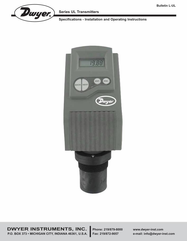
Series UL Transmitters
Specifications - Installation and Operating Instructions
Bulletin L-UL
DWYER INSTRUMENTS, INC. Phone: 219/879-8000 www.dwyer-inst.com
P.O. BOX 373 • MICHIGAN CITY, INDIANA 46361, U.S.A. Fax: 219/872-9057 e-mail: [email protected]
L-UL:SSS-1000 12/15/10 8:56 AM Page 1
Table of Contents
Chapter 1. Introduction
Specifications . . . . . . . . . . . . . . . . . . . . . . . . . . . . . . . . . . . . . . . . . . . . . . . . . . . . .2
Measuring Ranges . . . . . . . . . . . . . . . . . . . . . . . . . . . . . . . . . . . . . . . . . . . . . . . .2
Chapter 2. Installation
Precautions . . . . . . . . . . . . . . . . . . . . . . . . . . . . . . . . . . . . . . . . . . . . . . . . . . . . . .3
Installing the Unit on Threaded Flange/Thread-Free Flange . . . . . . . . . . . . . . . .3
Installing the Unit via Extension Pipes . . . . . . . . . . . . . . . . . . . . . . . . . . . . . . . . .4
Using a Conduit Adapter . . . . . . . . . . . . . . . . . . . . . . . . . . . . . . . . . . . . . . . . . . . .4
Non-Intrinsically Safe Connections . . . . . . . . . . . . . . . . . . . . . . . . . . . . . . . . . . . .4
Power Supply and Load Resistance Recommendations . . . . . . . . . . . . . . . . . . .4
Chapter 3. Set Up
Series UL Functions . . . . . . . . . . . . . . . . . . . . . . . . . . . . . . . . . . . . . . . . . . . . . . .5
Set Up and Function Access . . . . . . . . . . . . . . . . . . . . . . . . . . . . . . . . . . . . . . . . .5
Resetting the Unit . . . . . . . . . . . . . . . . . . . . . . . . . . . . . . . . . . . . . . . . . . . . . . . . .6
Entering Distance to Empty Level (Tank Height) . . . . . . . . . . . . . . . . . . . . . . . . . .6
Defining Interfering Signals . . . . . . . . . . . . . . . . . . . . . . . . . . . . . . . . . . . . . . . . . .6
Configuring 4 mA Current Output . . . . . . . . . . . . . . . . . . . . . . . . . . . . . . . . . . . . .7
Configuring 20 mA Current Output . . . . . . . . . . . . . . . . . . . . . . . . . . . . . . . . . . . .7
Selecting Low/High Dynamic Speed . . . . . . . . . . . . . . . . . . . . . . . . . . . . . . . . . .8
Defining Working Area . . . . . . . . . . . . . . . . . . . . . . . . . . . . . . . . . . . . . . . . . . . . . .8
Selecting Distance or Level Display . . . . . . . . . . . . . . . . . . . . . . . . . . . . . . . . . . .8
Entering Factor for Gas Compensation . . . . . . . . . . . . . . . . . . . . . . . . . . . . . . . . .9
Restoring the Default Settings . . . . . . . . . . . . . . . . . . . . . . . . . . . . . . . . . . . . . . . .9
Shifting the Blocking Distance . . . . . . . . . . . . . . . . . . . . . . . . . . . . . . . . . . . . . . . .9
Verifying the Version Number . . . . . . . . . . . . . . . . . . . . . . . . . . . . . . . . . . . . . . . .9
Defining 22 mA Signal Error Messages . . . . . . . . . . . . . . . . . . . . . . . . . . . . . . .10
Chapter 4. Open Channels (ULF)
Selecting the Flow Measurement Settings . . . . . . . . . . . . . . . . . . . . . . . . . . . . .10
Open Channel Flow Measurements . . . . . . . . . . . . . . . . . . . . . . . . . . . . . . . . . .10
Flume/Weir Types . . . . . . . . . . . . . . . . . . . . . . . . . . . . . . . . . . . . . . . . . . . . . . . .11
Flumes/Weirs - European Standard . . . . . . . . . . . . . . . . . . . . . . . . . . . . . . . . . .11
Rectangular Suppressed Sharp - Crested Weir (Type 1) . . . . . . . . . . . . . . . . . .11
Rectangular Contracted Sharp - Crested Weir (Type 2) . . . . . . . . . . . . . . . . . . .11
Trapezoidal (Cipolletti) Sharp - Crested Weir (Type 3) . . . . . . . . . . . . . . . . . . . .11
V-Notch (Triangular) Sharp - Crested Weir (Type 4) . . . . . . . . . . . . . . . . . . . . . .11
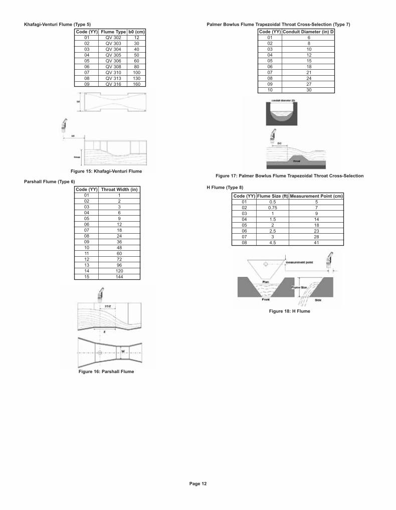
Khafagi-Venturi Flume (Type 5) . . . . . . . . . . . . . . . . . . . . . . . . . . . . . . . . . . . . . .12
Parshall Flume (Type 6) . . . . . . . . . . . . . . . . . . . . . . . . . . . . . . . . . . . . . . . . . . .12
Palmer Bowlus Flume Trapezoidal Throat Cross-Selection (Type 7) . . . . . . . . .12
H Flume (Type 8) . . . . . . . . . . . . . . . . . . . . . . . . . . . . . . . . . . . . . . . . . . . . . . . . .12
Neyrpic Venturi Flume/Long-Base Weir (Type 9) . . . . . . . . . . . . . . . . . . . . . . . .13
Flumes/Weirs – American Standard . . . . . . . . . . . . . . . . . . . . . . . . . . . . . . . . . .13
Rectangular Suppressed Sharp - Crested Weir (Type 1) . . . . . . . . . . . . . . . . . .13
Rectangular Contracted Sharp - Crested Weir (Type 2) . . . . . . . . . . . . . . . . . .13
Trapezoidal (Cipolletti) Sharp - Crested Weir (Type 3) . . . . . . . . . . . . . . . . . . . .13
V-Notch (Triangular) Sharp - Crested Weir (Type 4) . . . . . . . . . . . . . . . . . . . . . .13
Parshall Flume (Type 5) . . . . . . . . . . . . . . . . . . . . . . . . . . . . . . . . . . . . . . . . . . .14
Palmer Bowlus Flume Trapezoidal Throat Cross-Selection (Type 6) . . . . . . . . .14
H Flume (Type 7) . . . . . . . . . . . . . . . . . . . . . . . . . . . . . . . . . . . . . . . . . . . . . . . . .14
Leopold-Lagco Flume (Type 8) . . . . . . . . . . . . . . . . . . . . . . . . . . . . . . . . . . . . . .14
Chapter 5. Troubleshooting
22 mA Signal Error Messages . . . . . . . . . . . . . . . . . . . . . . . . . . . . . . . . . . . . . . .15
Appendix A – Gas Factor Table . . . . . . . . . . . . . . . . . . . . . . . . . . . . . . . . . . . . . .16
Appendix B – Installation Tips . . . . . . . . . . . . . . . . . . . . . . . . . . . . . . . . . . . . . . .16
Appendix C – Nomenclature . . . . . . . . . . . . . . . . . . . . . . . . . . . . . . . . . . . . . . . .17
Table of Figures
Figure 1: Front and Side View . . . . . . . . . . . . . . . . . . . . . . . . . . . . . . . . . . . . . . . . . .2
Figure 2: Threaded Flange/ Thread - Free Flange Monitoring . . . . . . . . . . . . . . . . .3
Figure 3: Extension Pipe Recommendation . . . . . . . . . . . . . . . . . . . . . . . . . . . . . . .4
Figure 4: Conduit Adapter . . . . . . . . . . . . . . . . . . . . . . . . . . . . . . . . . . . . . . . . . . . . .4
Figure 5: Non-Intrinsically Safe Positive Ground Connection . . . . . . . . . . . . . . . . . .4
Figure 6: Non-Intrinsically Safe Negative Ground Connection . . . . . . . . . . . . . . . . .4
Figure 7: Functions Menus . . . . . . . . . . . . . . . . . . . . . . . . . . . . . . . . . . . . . . . . . . . . .5
Figure 8: Display and Function Buttons . . . . . . . . . . . . . . . . . . . . . . . . . . . . . . . . . . .5
Figure 9: Scan Distance Process . . . . . . . . . . . . . . . . . . . . . . . . . . . . . . . . . . . . . . . .6
Figure 10: Defining Working Area . . . . . . . . . . . . . . . . . . . . . . . . . . . . . . . . . . . . . . .8
Figure 11: Rectangular Suppressed Sharp - Crested Weir . . . . . . . . . . . . . . . . . . .11
Figure 12: Rectangular Contracted Sharp - Crested Weir . . . . . . . . . . . . . . . . . . . .11
Figure 13: Trapezoidal (Cipolletti) Sharp - Crested Weir . . . . . . . . . . . . . . . . . . . . .11
Figure 14: V-Notch (Triangular) Sharp - Crested Weir . . . . . . . . . . . . . . . . . . . . . . .11
Figure 15: Khafagi-Venturi Flume . . . . . . . . . . . . . . . . . . . . . . . . . . . . . . . . . . . . . .12
Figure 16: Parshall Flume . . . . . . . . . . . . . . . . . . . . . . . . . . . . . . . . . . . . . . . . . . . .12
Figure 17: Palmer Bowlus Flume Trapezoidal Throat
Cross-Selection . . . . . . . . . . . . . . . . . . . . . . . . . . . . . . . . . . . . . . . . . . .12
Figure 18: H Flume . . . . . . . . . . . . . . . . . . . . . . . . . . . . . . . . . . . . . . . . . . . . . . . . .12
Figure 19: Neyrpic Venture Flume . . . . . . . . . . . . . . . . . . . . . . . . . . . . . . . . . . . . . .13
Figure 20: Long-Base Weir . . . . . . . . . . . . . . . . . . . . . . . . . . . . . . . . . . . . . . . . . . .13
Figure 21: Rectangular Suppresses Sharp - Crested Weir . . . . . . . . . . . . . . . . . . .13
Figure 22: Rectangular Contracted Sharp - Crested Weir . . . . . . . . . . . . . . . . . . .13
Figure 23: Trapeziodal (Cipolletti) Sharp - Crusted Weir . . . . . . . . . . . . . . . . . . . . .13
Figure 24: V-Notch (Triangular) Sharp - Crested Weir . . . . . . . . . . . . . . . . . . . . . . .13
Figure 25: Parshall Flume . . . . . . . . . . . . . . . . . . . . . . . . . . . . . . . . . . . . . . . . . . . .14
Figure 26: Palmer Boweus Flume Trapezoidal Throat
Cross-Selection . . . . . . . . . . . . . . . . . . . . . . . . . . . . . . . . . . . . . . . . . . .14
Figure 27: H Flume . . . . . . . . . . . . . . . . . . . . . . . . . . . . . . . . . . . . . . . . . . . . . . . . .14
Figure 28: Leopold Lagco Flume . . . . . . . . . . . . . . . . . . . . . . . . . . . . . . . . . . . . . . .14
Figure 29: Nomenclature . . . . . . . . . . . . . . . . . . . . . . . . . . . . . . . . . . . . . . . . . . . . .17
Page 1
L-UL:SSS-1000 12/15/10 8:56 AM Page 2
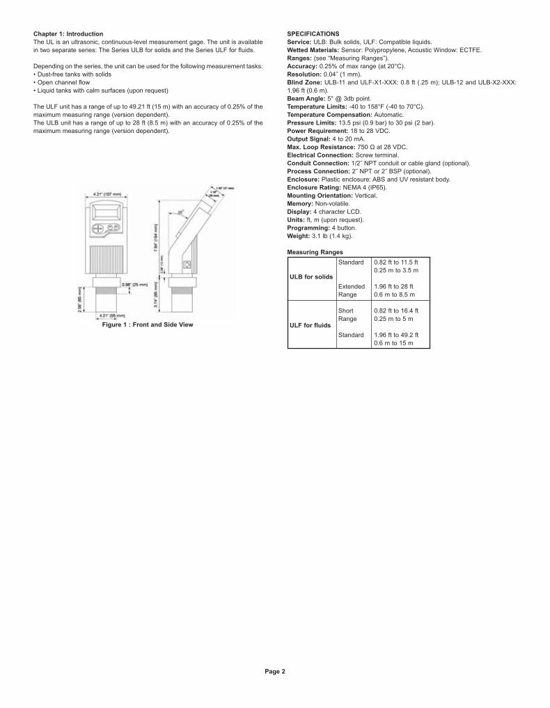
Chapter 1: Introduction
The UL is an ultrasonic, continuous-level measurement gage. The unit is available
in two separate series: The Series ULB for solids and the Series ULF for fluids.
Depending on the series, the unit can be used for the following measurement tasks:
• Dust-free tanks with solids
• Open channel flow
• Liquid tanks with calm surfaces (upon request)
The ULF unit has a range of up to 49.21 ft (15 m) with an accuracy of 0.25% of the
maximum measuring range (version dependent).
The ULB unit has a range of up to 28 ft (8.5 m) with an accuracy of 0.25% of the
maximum measuring range (version dependent).
SPECIFICATIONS
Service: ULB: Bulk solids, ULF: Compatible liquids.
Wetted Materials: Sensor: Polypropylene, Acoustic Window: ECTFE.
Ranges: (see “Measuring Ranges”).
Accuracy: 0.25% of max range (at 20°C).
Resolution: 0.04˝ (1 mm).
Blind Zone: ULB-11 and ULF-X1-XXX: 0.8 ft (.25 m); ULB-12 and ULB-X2-XXX:
1.96 ft (0.6 m).
Beam Angle: 5° @ 3db point.
Temperature Limits: -40 to 158°F (-40 to 70°C).
Temperature Compensation: Automatic.
Pressure Limits: 13.5 psi (0.9 bar) to 30 psi (2 bar).
Power Requirement: 18 to 28 VDC.
Output Signal: 4 to 20 mA.
Max. Loop Resistance: 750 Ω at 28 VDC.
Electrical Connection: Screw terminal.
Conduit Connection: 1/2˝ NPT conduit or cable gland (optional).
Process Connection: 2˝ NPT or 2˝ BSP (optional).
Enclosure: Plastic enclosure: ABS and UV resistant body.
Enclosure Rating: NEMA 4 (IP65).
Mounting Orientation: Vertical.
Memory: Non-volatile.
Display: 4 character LCD.
Units: ft, m (upon request).
Programming: 4 button.
Weight: 3.1 lb (1.4 kg).
Measuring Ranges
Page 2
ULB for solids
ULF for fluids
Standard
Extended
Range
Short
Range
Standard
0.82 ft to 11.5 ft
0.25 m to 3.5 m
1.96 ft to 28 ft
0.6 m to 8.5 m
0.82 ft to 16.4 ft
0.25 m to 5 m
1.96 ft to 49.2 ft
0.6 m to 15 m
Figure 1 : Front and Side View
L-UL:SSS-1000 12/15/10 8:56 AM Page 3
Chapter 2: Installing the Unit
Precautions
• Ensure that the unit is mounted in an area that meets the stated temperature,
pressure and technical specifications.
• Ensure that high-voltage sources or cables are at least 40˝ (1 m) away from the
sensor and its cable.
• Use round cables with minimum diameter of 0.24 to 0.28˝ (6 to 7 mm) to ensure
that the unit remains sealed per IP65 standards.
• Ensure that cables are routed correctly and tightened along walls or pipes.
• Installation and operation of this product should be performed, according to the
Product User Manual and Product Certification. Otherwise the use of this product
is prohibited.
When installing the unit ensure that it is:
• Mounted above the dead-zone area.
NOTE: If the device enters the blocking distance (dead
zone), it will not measure correctly.
• Positioned at least 1.64 ft (0.5 m) away from the tank walls.
Add 4˝ (10 cm) spacing for each 40˝ (1 m) in range.
• Perpendicular to the surface of the target.
NOTE: Even the slightest difference in angle may affect echo
quality.
• Placed as far as possible from noisy areas, such as a filling
inlet.
NOTE: When installed in a humid environment it is
recommended to position the sensor on a tripod on top of the
vessel.
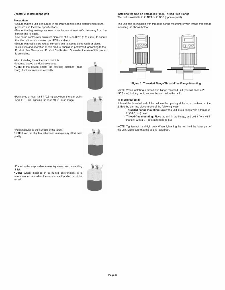
Installing the Unit on Threaded Flange/Thread-Free Flange
The unit is available in 2˝ NPT or 2˝ BSP (upon request).
The unit can be installed with threaded-flange mounting or with thread-free flange
mounting, as shown below:
Figure 2: Threaded Flange/Thread-Free Flange Mounting
NOTE: When installing a thread-free flange mounted unit, you will need a 2˝
(50.8 mm) locking nut to secure the unit inside the tank.
To Install the Unit:
1. Insert the threaded end of the unit into the opening at the top of the tank or pipe.
2. Bolt the unit into place in one of the following ways:
• Threaded-flange mounting: Screw the unit into a flange with a threaded
2˝ (50.8 mm) hole.
• Thread-free mounting: Place the unit in the flange, and bolt it from within
the tank with a 2˝ (50.8 mm) locking nut.
NOTE: Tighten nut hand tight only. When tightening the nut, hold the lower part of
the unit. Make sure that the seal is leak proof.
Page 3
L-UL:SSS-1000 12/15/10 8:56 AM Page 4
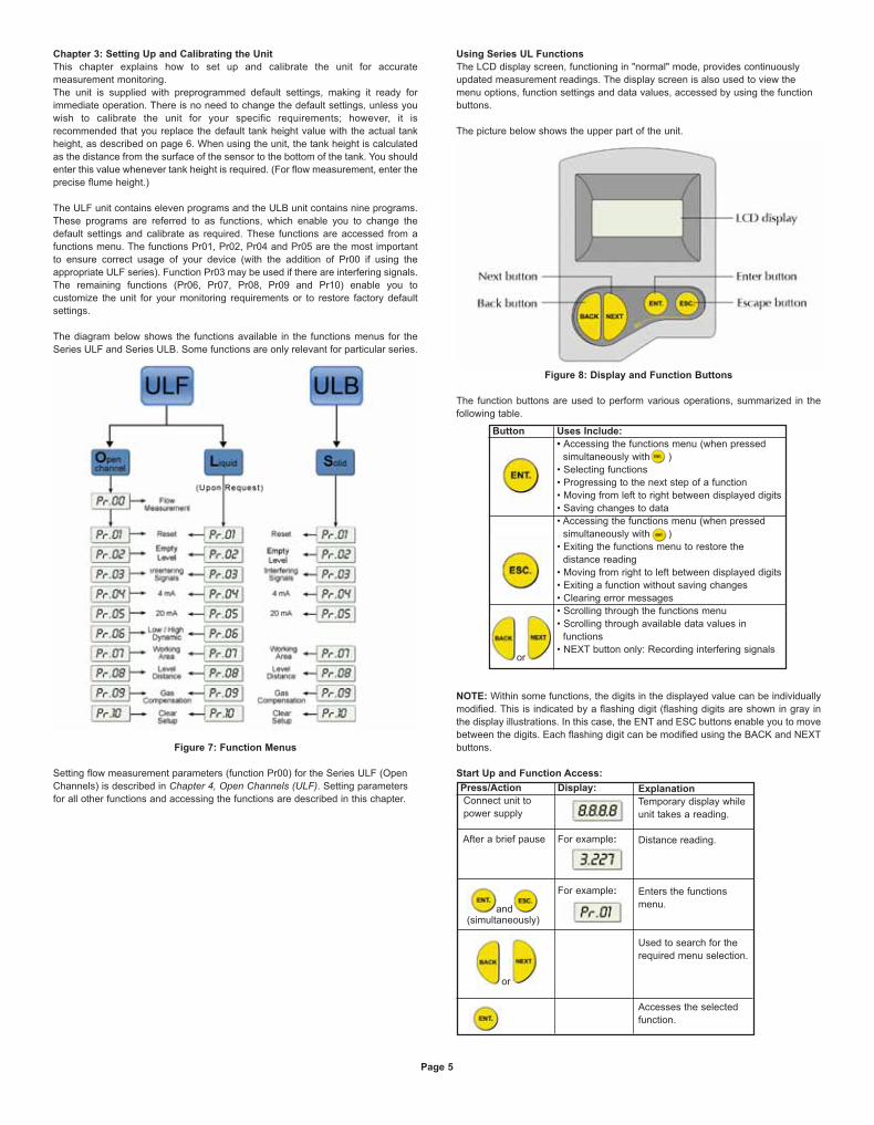
Installing the Unit Via Extension Pipes
If the level of the measured surface falls within the dead-zone area, you should use
an extension pipe to mount the unit.
When using an extension pipe, ensure that:
• The sensor is positioned in the center of the pipe.
• The pipe extension is exactly perpendicular to the surface
of the target.
• The internal pipe diameter is at least 3.0˝ (76.2 mm) wide.
• The pipe is preferably made of plastic and must have a
smooth interior surface.
• The pipe should not protrude inside the tank.
• The tank drilling should be at least the size of the internal
pipe diameter and have a smooth edge.
When installing the unit with extension pipes, measure from sensor’s lower edge
and follow these specifications:
NOTE:
1. It is always recommended to use interference signal feature (Pr03) to locate
interfering signals when using an extension pipe.
2. The sensor's lower edge may be
a) aligned with the extension pipe's upper edge or
b) protrude it by up to 2.56˝ (6.5 cm). See Figure 3 below:
Figure 3: Extension Pipe Recommendation
Using a Conduit Adapter
1. Remove the four retaining screws from the conduit adapter cover.
2. Pull the electrical wires through the 1/2˝ NPT conduit connection.
3. Connect the -24 V wire to Terminal 1, connect the +24 V wire to Terminal 2 on
the wiring block.
4. Return the adapter's cover to its place properly. Make sure that the O-ring is
placed correctly. Fasten the four retaining screws.
Figure 4: Conduit Adapter
NOTE: The conduit adapter should not exceed a torque of 50 lb-in.
To maintain a proper seal, make sure that conduit is firmly screwed to the conduit's
adaptor.
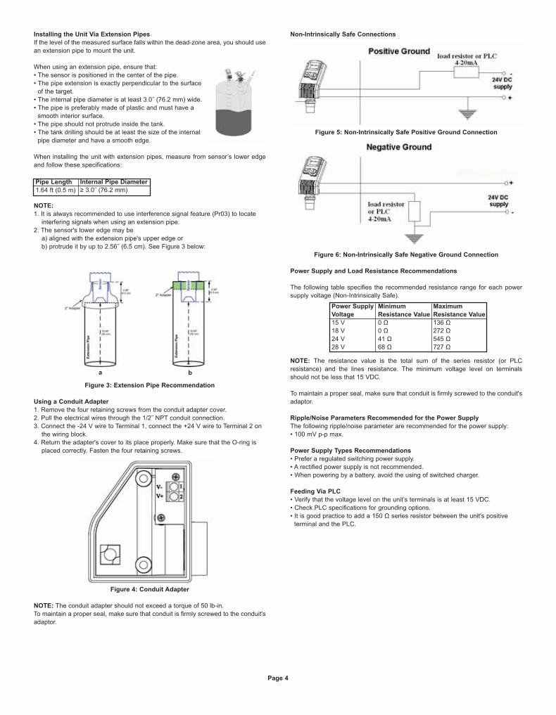
Non-Intrinsically Safe Connections
Figure 5: Non-Intrinsically Safe Positive Ground Connection
Figure 6: Non-Intrinsically Safe Negative Ground Connection
Power Supply and Load Resistance Recommendations
The following table specifies the recommended resistance range for each power
supply voltage (Non-Intrinsically Safe).
NOTE: The resistance value is the total sum of the series resistor (or PLC
resistance) and the lines resistance. The minimum voltage level on terminals
should not be less that 15 VDC.
To maintain a proper seal, make sure that conduit is firmly screwed to the conduit's
adaptor.
Ripple/Noise Parameters Recommended for the Power Supply
The following ripple/noise parameter are recommended for the power supply:
• 100 mV p-p max.
Power Supply Types Recommendations
• Prefer a regulated switching power supply.
• A rectified power supply is not recommended.
• When powering by a battery, avoid the using of switched charger.
Feeding Via PLC
• Verify that the voltage level on the unit’s terminals is at least 15 VDC.
• Check PLC specifications for grounding options.
• It is good practice to add a 150 Ω series resistor between the unit's positive
terminal and the PLC.
Pipe Length
1.64 ft (0.5 m)
Internal Pipe Diameter
≥ 3.0˝ (76.2 mm)
Power Supply
Voltage
15 V
18 V
24 V
28 V
Minimum
Resistance Value
0 Ω
0 Ω
41 Ω
68 Ω
Maximum
Resistance Value
136 Ω
272 Ω
545 Ω
727 Ω
Page 4
a b
L-UL:SSS-1000 12/15/10 8:56 AM Page 5
Chapter 3: Setting Up and Calibrating the Unit
This chapter explains how to set up and calibrate the unit for accurate
measurement monitoring.
The unit is supplied with preprogrammed default settings, making it ready for
immediate operation. There is no need to change the default settings, unless you
wish to calibrate the unit for your specific requirements; however, it is
recommended that you replace the default tank height value with the actual tank
height, as described on page 6. When using the unit, the tank height is calculated
as the distance from the surface of the sensor to the bottom of the tank. You should
enter this value whenever tank height is required. (For flow measurement, enter the
precise flume height.)
The ULF unit contains eleven programs and the ULB unit contains nine programs.
These programs are referred to as functions, which enable you to change the
default settings and calibrate as required. These functions are accessed from a
functions menu. The functions Pr01, Pr02, Pr04 and Pr05 are the most important
to ensure correct usage of your device (with the addition of Pr00 if using the
appropriate ULF series). Function Pr03 may be used if there are interfering signals.
The remaining functions (Pr06, Pr07, Pr08, Pr09 and Pr10) enable you to
customize the unit for your monitoring requirements or to restore factory default
settings.
The diagram below shows the functions available in the functions menus for the
Series ULF and Series ULB. Some functions are only relevant for particular series.
Figure 7: Function Menus
Setting flow measurement parameters (function Pr00) for the Series ULF (Open
Channels) is described in Chapter 4, Open Channels (ULF). Setting parameters
for all other functions and accessing the functions are described in this chapter.
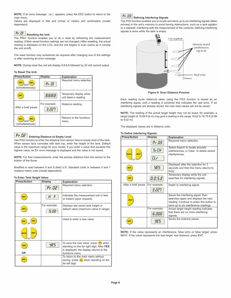
Using Series UL Functions
The LCD display screen, functioning in "normal" mode, provides continuously
updated measurement readings. The display screen is also used to view the
menu options, function settings and data values, accessed by using the function
buttons.
The picture below shows the upper part of the unit.
Figure 8: Display and Function Buttons
The function buttons are used to perform various operations, summarized in the
following table.
NOTE: Within some functions, the digits in the displayed value can be individually
modified. This is indicated by a flashing digit (flashing digits are shown in gray in
the display illustrations. In this case, the ENT and ESC buttons enable you to move
between the digits. Each flashing digit can be modified using the BACK and NEXT
buttons.
Start Up and Function Access:
Button Uses Include:
• Accessing the functions menu (when pressed
simultaneously with )
• Selecting functions
• Progressing to the next step of a function
• Moving from left to right between displayed digits
• Saving changes to data
• Accessing the functions menu (when pressed
simultaneously with )
• Exiting the functions menu to restore the
distance reading
• Moving from right to left between displayed digits
• Exiting a function without saving changes
• Clearing error messages
• Scrolling through the functions menu
• Scrolling through available data values in
functions
• NEXT button only: Recording interfering signals
Press/Action
Connect unit to
power supply
After a brief pause
Display:
For example:
For example:
Explanation
Temporary display while
unit takes a reading.
Distance reading.
Enters the functions
menu.
Used to search for the
required menu selection.
Accesses the selected
function.
or
and(simultaneously)
Page 5
or
L-UL:SSS-1000 12/15/10 8:58 AM Page 6
NOTE: If an error message appears, press the ESC button to return to the
main menu.
Values are displayed in feet and inches or meters and centimeters (model
dependent).
Resetting the Unit
The PR01 function enables you to do a reset by refreshing the measurement
reading. (Other saved function settings are not changed.) After resetting, the actual
reading is displayed on the LCD, and the unit begins to scan (same as in turning
the unit on/off).
The reset function may sometimes be required after changing one of the settings
or after receiving an error message.
NOTE: During reset the unit will display 8.8.8.8 followed by 22 mA current output.
To Reset The Unit:
Entering Distance to Empty Level
Use Pr02 function to enter the distance from sensor face to empty level of the tank.
When sensor face coincides with tank top, enter the height of the tank. Default
value is the maximum range for your model. If you enter a value that exceeds this
highest value, an Err error message is displayed and the value is not saved.
NOTE: For flow measurements, enter the precise distance from the sensor to the
bottom of the flume.
Modified to read between 0 and 5 (feet) U.S. Standard Units or between 0 and 1
(meters) metric units (model dependent).
To Enter Tank Height Value:
Defining Interfering Signals
The Pr03 function enables you to locate and store up to six interfering signals (false
echoes) in the unit’s memory to avoid having obstructions, such as a tank agitator
or a sidewall, interfering with the measurement of the contents. Defining interfering
signals is done while the tank is empty.
Figure 9: Scan Distance Process
Each reading (scan distance) taken using the Pr03 function is stored as an
interfering signal, until a reading is achieved that indicates the real echo. If six
interfering signals are already stored, the next read values will not be saved.
NOTE: The reading of the actual target height may not be exact, for example, a
target height of 19.69 ft (6 m) may give a reading in the range 19.62 to 19.75 ft (5.98
to 6.02 m).
The displayed values are in distance units.
To Define Interfering Signals:
NOTE: If the value represents an interference, false echo or false target: press
NEXT. If the value represents the real target, real distance: press ENT.
Press/Action
After a brief pause
Display
For example:
Explanation
Required menu selection.
Temporary display while
unit takes a reading.
Distance reading.
Returns to the functions
menu.
and(simultaneously)
and(simultaneously)
Press/Action Display
For example:
Explanation
Required menu selection.
Indicates the measurement unit in feet
or meters (upon request).
Displays last saved tank height or
default value (maximum value in range).
Used to enter a new value.
To save the new value, press when
standing on the far right digit. After YES
is displayed, the display returns to the
functions menu.
To return to the main menu without
saving, press when standing on the
far left digit.
or
or
OR
Press/Action
After a brief pause
Display
For example:
For example:
Explanation
Required menu selection.
Select Search to locate acoustic
interferences, or Clear to delete stored
interferences.
Displayed after the selection for 3
seconds and then the menu returns to
Pr03.
Temporary display while the unit
searches for interfering signals.
Depth to interfering signal.
Saves the interfering signal, then
searches again and displays the next
reading. Continue to press this button to
save up to six interference readings.
Actual target height reading indicates
that there are no more interfering
signals.
Saves the entered values.
or
Page 6
L-UL:SSS-1000 12/15/10 9:01 AM Page 7
Configuring 4 mA Current Output
Pr04 function enables you to enter values to be used as the 4 mA mark for remote
monitoring. You can define the 4 mA values for level, distance or flow
measurements (depending on series). The measurement value types should be
defined in Pr04. These definitions will be applicable as well for the 20 mA values
defined in Pr05.
To set 4 mA and 20 mA for level measurements you should configure Pr04 and
Pr05 for level values.
For example, if we measure a tank with tank height configured for 16.4 ft (5.0 m),
the 4 mA values will represent zero tank level and 20 mA values will represent full
tank level. Therefore, the value entered in Pr04 will be 0.0 ft (0.0 m) and the value
entered in Pr05 will be 16.4 ft (5.0 m).
When setting 4 mA and 20 mA for distance measurements, 4 mA values will
represent the minimal distance between the surface of the target and the sensor
and 20 mA values will represent the maximal distance between the sensor and the
surface of the target. Therefore, 4 mA represents the full part of the tank and 20 mA
represents the empty part of the tank.
NOTE: The values for 4 mA and 20 mA must be different, otherwise an Err (error
message) is displayed.
The values for 4 mA and 20 mA should not be greater than the value used for the
tank height (Pr02). Because of the dead-zone, the distance between the sensor
and the surface of the target at its highest level should be a minimum of 0.82 ft
(0.25 m) for ULB Standard-Range and ULF Short-Range models, or 1.96 ft (0.6 m)
for ULB Extended-Range and ULF Standard-Range models.
The first digit of the 4 mA value can be modified to read between 0 and 5 (feet) for
U.S. Standard Units or between 0 and 1 (meters) metric units (upon request).
After accessing the Pr04 function, the unit generates a fixed current of 22 mA on
the 4 to 20 mA line. When the unit reverts to regular scanning mode, the 4 to 20
mA line returns to regular functioning.
The default values for 4 mA and 20 mA in both the ULB and ULF Liquid Series are
level.
The default values for 4 mA and 20 mA in ULF Open Channel Series are flow.
When changing from one measurement mode to another, the measurement units
will be changed automatically (for example, when changing from level mode to flow
mode, the units will change from feet to GPM or meters to M3/H (depending on the
model).
The measurement mode selected for the 4 to 20 mA values will not influence the
measurement mode selected for the display (Pr08). In case of power rest,
measurement configuration (level, distance, flow) will be saved according to the
unit's last configuration.
Configuring 20 mA Current Output
The Pr05 function enables you to enter values to be used as the 20 mA mark for
remote monitoring.
To Enter 20 mA Values:
NOTE: The type of measurement (level, distance or flow) selected in Pr04 is also
applicable for Pr05.
The values for 4 mA and 20 mA must be different; otherwise an Err (error message)
is displayed.
The values for 4 mA and 20 mA should not be higher than the value used for the
tank height (Pr02).
The first digit of the 20 mA value can be modified to read between 0 and 5 for U.S.
Standard Units or between 0 and 1 for metric units (model dependent).
After accessing the Pr05 function, the unit generates a fixed current of 22 mA on
the 4 to 20 mA line. When the unit reverts to regular scanning mode, the 4 to 20
mA line returns to regular functioning.
Please refer to Chapter 5 Troubleshooting for 20 mA error indications.
Press/Action Display
For example:
For example:
Explanation
Required menu selection.
Select the format for 4 mA and 20 mA
values to level (L000), distance (d000)
or flow (F000) (depending on model).
Last saved 4 mA level or zero default
value.
Used to enter a new value.
To save the new value, press when
standing on the far right digit. After YES
is displayed, the display returns to the
functions menu.
To return to the main menu without
saving, press when standing on the
far left digit.
or
or
or
Press/Action Display
For example:
Explanation
Required menu selection.
Last saved 20 mA level or default value
(maximum value in range).
Used to enter a new value.
To save the new value, press when
standing on the far right digit. After YES
is displayed, the display returns to the
functions menu.
To return to the main menu without
saving, press when standing on the
far left digit.
or
or
OR
Page 7
L-UL:SSS-1000 12/15/10 9:03 AM Page 8
Selecting Low/High Dynamic Speed (ULF Series Only)
The Pr06 function enables you to choose the required speed level. There are two
settings available:
• SE 0: Low dynamic mode (default setting). This mode provides slower readings
with a greater degree of accuracy (rate of up to 31˝/80 cm per min).
• Fail Safe: 10 minutes.
• SE 1: High dynamic mode. This mode provides faster readings but with less
precision (rate of up to 39˝/100 cm per min).
• Fail Safe: 3 minutes.
NOTE: Fail Safe timer determines the waiting period from an echo loss until a
transmission of an error signal.
To Select the Speed Mode:
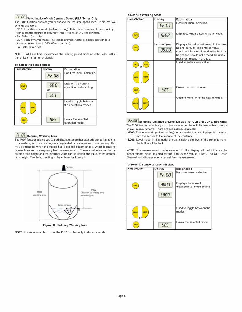
Defining Working Area
The Pr07 function allows you to add distance range that exceeds the tank's height,
thus enabling accurate readings of complicated tank shapes with conic ending. This
may be required when the vessel has a conical bottom shape, which is causing
false echoes and consequently faulty measurements. The minimal value can be the
entered tank height and the maximal value can be double the value of the entered
tank height. The default setting is the entered tank height.
Figure 10: Defining Working Area
NOTE: It is recommended to use the Pr07 function only in distance mode.
To Define a Working Area:
Selecting Distance or Level Display (for ULB and ULF Liquid Only)
The Pr08 function enables you to choose whether the unit displays either distance
or level measurements. There are two settings available:
• d000: Distance mode (default setting): In this mode, the unit displays the distance
from the sensor to the surface of the contents.
• L000: Level mode: In this mode, the unit displays the level of the contents from
the bottom of the tank.
NOTE: The measurement mode selected for the display will not influence the
measurement mode selected for the 4 to 20 mA values (Pr04). The ULF Open
Channel only displays open channel flow measurement.
To Select Distance or Level Display:
Press/Action Display Explanation
Required menu selection.
Displays the current
operation mode setting.
Used to toggle between
the operations modes.
Saves the selected
operation mode.
or
or
Press/Action Display
For example:
Explanation
Required menu selection.
Displayed when entering the function.
Displays the value last saved in the tank
height (default). The entered value
should not be more than double the tank
height and should not exceed the unit's
maximum measuring range.
Used to enter a new value.
Saves the entered value.
Used to move on to the next function.
or
or
or
Press/Action Display Explanation
Required menu selection.
Displays the current
distance/level mode setting.
Used to toggle between the
modes.
Saves the selected mode.
or
or
Page 8
L-UL:SSS-1000 12/15/10 9:06 AM Page 9
Entering Factor for Gas Compensation
Function Pr09 enables you to compensate for sound velocity changes in different
types of gasses. You can enter the appropriate factor for each type of gas listed on
the “Gas Factor Table” (Appendix A). For example, the sound velocity in air (at
room temperature) is 1125 ft/sec (343 m/sec) and for Methane (Ch4) 1463 ft/sec
(445.82 m/sec). Therefore, a factor of 1463/1125 = 1.30 should be entered to
compensate for this type of gas. This factor will compensate in cases when the gas
compound consists of 100% Methane. In case the gas is not pure, the sound
velocity cannot be estimated and therefore a minor deviation could appear. It is
recommended to use a reference measurement indicator (using a tape or other
measuring device) and compare the measurement results between the unit and the
reference measurement indicator. If the result is correct, press ENT. If the accuracy
deviation is higher than expected, continue and calibrate the factor to meet the gas
maintained in the vessel. For example, if the gas composition consists of water and
gas you can add ± 0.01 to the factor figure already entered, to meet your
application requirements.
The “Gas Factor Table” supports up to 32 different types of gasses. For any other
type of gas, not included in this table, please contact Dwyer Customer Support,
(www.dwyer-inst.com).
NOTE: Repeat this procedure if the measurement results differ from the actual
material level measured with a reference tape (or other reference measurement
method). Add or reduce 0.01 to calibrate the factor figure already entered.
Updated on-screen results may take a few seconds to appear.
Restoring the Default Settings
The Pr10 function allows clearing all user-defined settings and reverting to the
default factory settings.
Default factory settings are:
Pr00: GPM 1U01 or M³/Hr 1E01
Pr02: Sbd 00.00, E000, Tank Height =default
Pr03: Resets all interfering signals
Pr04: Solid/Liquid device L000, 00.00 or
Flow device F000, 00.00
Pr05: Solid/Liquid device Tank Height = Pr.02
Flow device 55500 M³/Hr or 244400 GPM
Pr06: SE 0 (Liquid and Flow)
Pr07: Tank Height = Pr.02
Pr08: Solid/Liquid device d000
Pr09: 01.00
NOTE: If you decide not to revert to the default settings, press ESC when CLCL is
displayed. A redo option is not available when ENT has been pressed.
To Restore the Default Settings:
Shifting the Blocking Distance
This function enables you to define an area in which measurement results would
be ignored. This option is applicable for installations requiring extension pipes or
nuzzles positioned above the material level. This area should approximately fit the
pipe/nuzzle length to eliminate false echoes and to provide accurate and stable
measurement readings.
• To Shift the Blocking Distance:
Follow the directions given for Entering Distance to Empty Level (Tank Height), page 6. Instead of entering the tank height value, enter 00.01, and continue as
follows:
NOTE: Shifting of the blocking distance is limited to 4.9 ft (1.5 m). The value
entered to the SBD incorporates the Dead Zone Value.
Pr10 (Clear) reverts the blocking distance to its default.
Echo received from the defined blocking distance area will be ignored by the unit
and the measurement result will be based on the next echo.
When installing via extension pipe, it is recommended to keep approx. 2˝ (5 cm)
gap between the shortest distance to target (maximal level) and the lower pipe
edge. Set the SBD length to a value that is 2˝ (5 cm) smaller than the distance from
the sensor's lower edge to pipe's lower edge, in order to avoid second harmony
interference.
Verifying the Version Number
In addition to the functions described, you can verify the UL series version
number.
• To Verify the Version Number:
Follow the directions given for Entering Distance to Empty Level (Tank Height), page 6. Instead of entering the tank height value, enter 00.17, and continue as
follows:
Page 9
Press/Action Display
For example:
Explanation
Required menu selection.
Default screen.
Default value.
Choose a factor from the “Gas FactorTable” (Appendix A).
This is the factor for Ethanol.
Saves the chosen gas factor.
or
or
Press/Action Display Explanation
Required menu selection.
Reverts all settings to default factory
settings.
Press/Action Display
For example:
Explanation
Insert this code to enter the blocking
distance area.
This message will flash for a few
seconds, indicating an entry to the
blocking distance area.
Shifts the blocking distance to 2.46 ft
(0.75 m).
Saves this entry and returns to Pr02.
or
or
Press/Action
After a brief pause
Display Explanation
Displays the version number.
L-UL:SSS-1000 12/15/10 9:08 AM Page 10
Defining 22 mA Signal Error Messages
The unit allows you to define if the following signal error indications: Near Zone and
Lost Echo, will be active when the current output reaches 22 mA. The default
setting enables 22 mA analog current and error messages to appear on its LCD
display.
Near Zone - Whenever the distance is below the defined Dead Zone (depending
on the series you are using) message will be displayed on the LCD.
Lost Echo - Whenever the echo is lost, or in cases when the measurement results
exceed the tank height or when a returned echo is not received message will
be displayed on the LCD.
You can choose to enable or disable these error messages and 22 mA analog
signal as follows:
• d000: Disable
• E000: Enable (default setting)
Refer to Chapter 5, Troubleshooting for a detailed list of the 22 mA signal error
messages.
• To Disable/Enable 22 mA Signal Error in the Unit:
Follow the directions given for Entering Distance to Empty Level (Tank Height),page 6. Instead of entering the tank height value, enter 00.16, and continue as
follows:
NOTE: When the error signals are disabled the following current outputs will be
displayed:
(Level or flow measurement): F.F.F.F will indicate 20 mA and E.E.E.E will indicate
4 mA.
(Distance measurement): F.F.F.F will indicate 4 mA and E.E.E.E will indicate
20 mA.
Chapter 4: Open Channels (ULF)
This section describes how to set flow measurement parameters for open channels
and explains the flume/weir codes methodology used when setting up flow
measurements.
Selecting the Flow Measurement Settings
The Pr00 function enables you to select one of the preset flumes/weirs settings for
flow measurements. This function is available only in the ULF Open Channel
series. When setting flow measurement parameters in the Pr00 function, the
flume/weir type value (X) is entered first, followed by the letter (U) or (E) that
represents either American (USA) or European standard flume/weir. The code
value (YY) represents the appropriate flume/weir dimensions in the following
format: . The open channel types and codes are described in Open ChannelsFlow Measurement.
NOTE: Refer to Chapter 3, Setting Up and Calibrating the Unit, for an explanation
of accessing and using the functions menu.
All flow measurement values are displayed divided by 1000.
• To Select the Flow Measurement Settings:
Open Channels Flow Measurements
The flume/weir type code methodology used when setting up open channels is
based on three digits: X(U/E)YY
Where:
X refers to the particular flume/weir type
U/E refers to either American or European standard flumes/weirs
YY refers to the specific flume/weir dimensions
The types of flumes/weirs are available in American standard or European standard
(upon request). When working in American standard the default flow measurement
units will be GPM, and in European standard the default flow measurement units
will be M³/Hr.
Page 10
Press/Action Display Explanation
Choose disable.
Used to toggle between the modes.
Disables the 22 mA error messages.
or
Press/Action Display
For example:
Explanation
Required menu selection.
Indicates the measurement unit for flow
in GPM (American standard) or M3
/h
(metric standard) (upon request).
Displays last saved flow measurement
setting or default value, with first digit
flashing U – American standard or E –
European standard (upon request).
Use to select a new type value (X).
Last two digits of the display flash.
Use to select a new flume/weir length
code (YY).
Selected values are saved.
or
or
L-UL:SSS-1000 12/15/10 9:10 AM Page 11
Flume/Weir Types
This is the first value (X) entered for the Pr00 function. The following flume/weir
types are available both in European and American standard:
Flumes/Weirs - European Standard
Rectangular Suppressed Sharp-Crested Weir (Type 1)
Rectangular Contracted Sharp-Crested Weir (Type 2 )
Trapezoidal (Cipolletti) Sharp-Crested Weir (Type 3)
V-Notch (Triangular) Sharp-Crested Weir (Type 4)
Page 11
European Standard
Pages 11-13
Rectangular Suppressed
Sharp-Crested Weir, Page 11
Rectangular Contracted Sharp-
Crested Weir, Page 11
Trapezoidal (Cipolletti) Sharp-
Crested Weir, Page 11
V-notch (Triangular) Sharp-
Crested Weir, Page 11
Khafagi-Venturi Flume, Page 12
Parshall Flume, Page 12
Palmer Bowlus Flume
Trapezoidal Throat Cross-
Selection, Page 12
H Flume, Page 12
Neyrpic Venturi Flume/Long-
Base Weir, Page 13
Type (X)
1
2
3
4
5
6
7
8
9
American Standard
Pages 13-14
Rectangular Suppressed Sharp-
Crested Weir, Page 13
Rectangular Contracted Sharp-
Crested Weir, Page 13
Trapezoidal (Cipolletti) Sharp-
Crested Weir, Page 13
V-notch (Triangular) Sharp-Crested
Weir, Page 13
Parshall Flume, Page 14
Palmer Bowlus Flume Trapezoidal
Throat Cross-Selection, Page 14
H Flume, Page 14
Leopold-Lagco Flume,
Page 14
Code (YY)
01
02
03
04
05
06
07
08
Crest Length (cm)
20
40
60
80
100
150
200
300
Figure 11: Rectangular Suppressed Sharp-Crested Weir
Code (YY)
01
02
03
04
05
06
07
08
09
10
Crest Length (cm)
20
30
40
50
60
80
100
150
200
300
Figure 12: Rectangular Contracted Sharp-Crested Weir
Code (YY)
01
02
03
04
05
06
07
08
Crest Length (cm)
30
45
60
80
100
150
200
300
Figure 13: Trapezoidal (Cipolletti) Sharp-Crested Weir
Code (YY)
01
02
03
04
05
06
07
08
09
10
V-Notch Angle (°)
90
60
53.8
45
30
28.4
22.5
90
45
22.5
Figure 14: V-Notch (Triangular) Sharp-Crested Weir
British Standard
L-UL:SSS-1000 12/15/10 9:10 AM Page 12
Khafagi-Venturi Flume (Type 5)
Parshall Flume (Type 6)
Palmer Bowlus Flume Trapezoidal Throat Cross-Selection (Type 7)
H Flume (Type 8)
Page 12
Code (YY)
01
02
03
04
05
06
07
08
09
Flume Type
QV 302
QV 303
QV 304
QV 305
QV 306
QV 308
QV 310
QV 313
QV 316
Figure 15: Khafagi-Venturi Flume
Code (YY)
01
02
03
04
05
06
07
08
09
10
11
12
13
14
15
Throat Width (in)
1
2
3
6
9
12
18
24
36
48
60
72
96
120
144
Figure 16: Parshall Flume
Code (YY)
01
02
03
04
05
06
07
08
09
10
Conduit Diameter (in) D
6
8
10
12
15
18
21
24
27
30
Figure 17: Palmer Bowlus Flume Trapezoidal Throat Cross-Selection
Code (YY)
01
02
03
04
05
06
07
08
Flume Size (ft)
0.5
0.75
1
1.5
2
2.5
3
4.5
Figure 18: H Flume
Measurement Point (cm)
5
7
9
14
18
23
28
41
b0 (cm)
12
30
40
50
60
80
100
130
160
L-UL:SSS-1000 12/15/10 9:10 AM Page 13
Neyrpic Venturi Flume/Long-Base Weir (Type 9)
Flumes/Weirs - American Standard
Rectagular Suppressed Sharp-Crested Weir (Type 1)
Rectangular Contracted Sharp-Crested Weir (Type 2)
Trapezoidal (Cipolletti) Sharp-Crested Weir (Type 3)
V-Notch (Triangular) Sharp-Crested Weir (Type 4)
Page 13
Code (YY)
01
02
03
04
05
06
07
08
09
Venturi Flume Type
1253AX
1253AY
1253AZ
1253A
1253B
1253C
1253D
1253E
1253F
Figure 19: Neyrpic Venturi Flume
Code (YY)
10
11
12
13
Long Base Weir Type
1245A
1245B
1245C
1245D
Figure 20: Long-Base Weir
Figure 21: Rectangular Suppressed Sharp-Crested Weir
Code (YY)
01
02
03
04
05
06
07
08
09
Crest Length (in)
12.00
18.00
24.00
30.00
36.00
48.00
60.00
72.00
96.00
Figure 22: Rectangular Contracted Sharp-Crested Weir
Code (YY)
01
02
03
04
05
06
07
08
09
Crest Length (in)
12.00
18.00
24.00
30.00
36.00
48.00
60.00
72.00
96.00
Figure 23: Trapezoidal (Cipolletti) Sharp-Crested Weir
Code (YY)
01
02
03
04
05
06
07
08
09
Crest Length (in)
12.00
18.00
24.00
30.00
36.00
48.00
60.00
72.00
96.00
Code (YY)
01
02
03
04
05
V-Notch Angle (°)
90
60
45
30
22.5
Figure 24: V-Notch (Triangular) Sharp-Crested Weir
L-UL:SSS-1000 12/15/10 9:10 AM Page 14
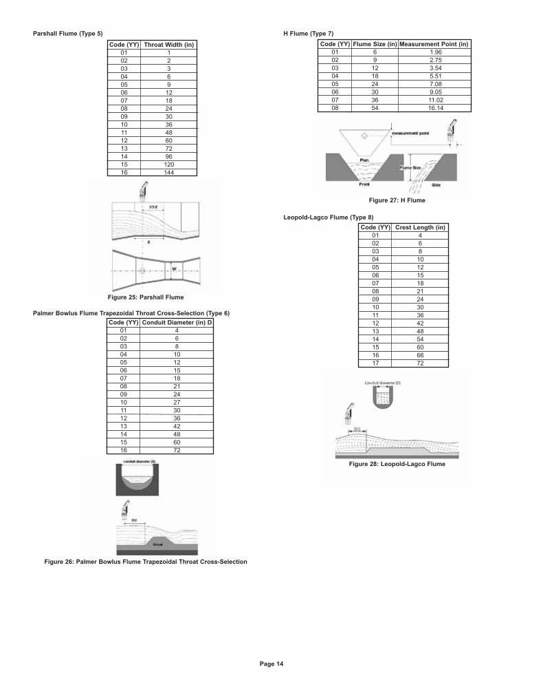
Parshall Flume (Type 5)
Palmer Bowlus Flume Trapezoidal Throat Cross-Selection (Type 6)
H Flume (Type 7)
Leopold-Lagco Flume (Type 8)
Page 14
Code (YY)
01
02
03
04
05
06
07
08
09
10
11
12
13
14
15
16
Throat Width (in)
1
2
3
6
9
12
18
24
30
36
48
60
72
96
120
144
Figure 25: Parshall Flume
Code (YY)
01
02
03
04
05
06
07
08
09
10
11
12
13
14
15
16
Conduit Diameter (in) D
4
6
8
10
12
15
18
21
24
27
30
36
42
48
60
72
Figure 26: Palmer Bowlus Flume Trapezoidal Throat Cross-Selection
Code (YY)
01
02
03
04
05
06
07
08
Flume Size (in)
6
9
12
18
24
30
36
54
Figure 27: H Flume
Measurement Point (in)
1.96
2.75
3.54
5.51
7.08
9.05
11.02
16.14
Code (YY)
01
02
03
04
05
06
07
08
09
10
11
12
13
14
15
16
17
Crest Length (in)
4
6
8
10
12
15
18
21
24
30
36
42
48
54
60
66
72
Figure 28: Leopold-Lagco Flume
L-UL:SSS-1000 12/15/10 9:10 AM Page 15
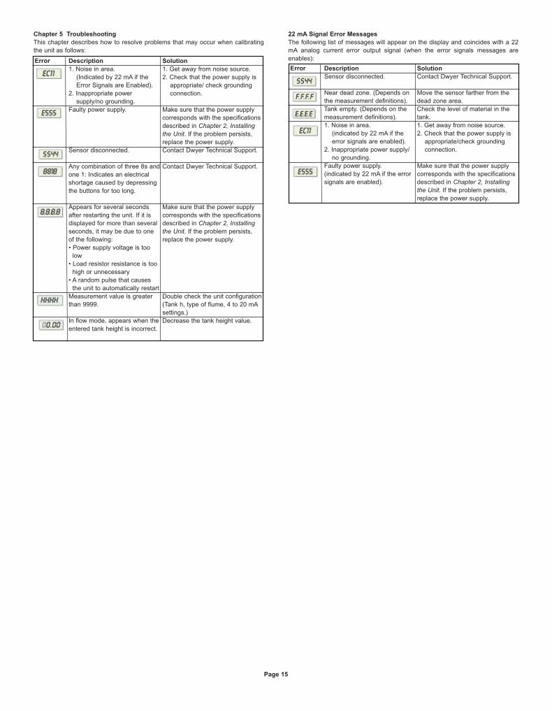
Chapter 5 Troubleshooting
This chapter describes how to resolve problems that may occur when calibrating
the unit as follows:
22 mA Signal Error Messages
The following list of messages will appear on the display and coincides with a 22
mA analog current error output signal (when the error signals messages are
enables):Error Description
1. Noise in area.
(Indicated by 22 mA if the
Error Signals are Enabled).
2. Inappropriate power
supply/no grounding.
Faulty power supply.
Sensor disconnected.
Any combination of three 8s and
one 1: Indicates an electrical
shortage caused by depressing
the buttons for too long.
Appears for several seconds
after restarting the unit. If it is
displayed for more than several
seconds, it may be due to one
of the following:
• Power supply voltage is too
low
• Load resistor resistance is too
high or unnecessary
• A random pulse that causes
the unit to automatically restart
Measurement value is greater
than 9999.
In flow mode, appears when the
entered tank height is incorrect.
Solution
1. Get away from noise source.
2. Check that the power supply is
appropriate/ check grounding
connection.
Make sure that the power supply
corresponds with the specifications
described in Chapter 2, Installingthe Unit. If the problem persists,
replace the power supply.
Contact Dwyer Technical Support.
Contact Dwyer Technical Support.
Make sure that the power supply
corresponds with the specifications
described in Chapter 2, Installingthe Unit. If the problem persists,
replace the power supply.
Double check the unit configuration
(Tank h, type of flume, 4 to 20 mA
settings.)
Decrease the tank height value.
Error Description
Sensor disconnected.
Near dead zone. (Depends on
the measurement definitions).
Tank empty. (Depends on the
measurement definitions).
1. Noise in area.
(indicated by 22 mA if the
error signals are enabled).
2. Inappropriate power supply/
no grounding.
Faulty power supply.
(indicated by 22 mA if the error
signals are enabled).
Solution
Contact Dwyer Technical Support.
Move the sensor farther from the
dead zone area.
Check the level of material in the
tank.
1. Get away from noise source.
2. Check that the power supply is
appropriate/check grounding
connection.
Make sure that the power supply
corresponds with the specifications
described in Chapter 2, Installingthe Unit. If the problem persists,
replace the power supply.
Page 15
L-UL:SSS-1000 12/15/10 9:11 AM Page 16
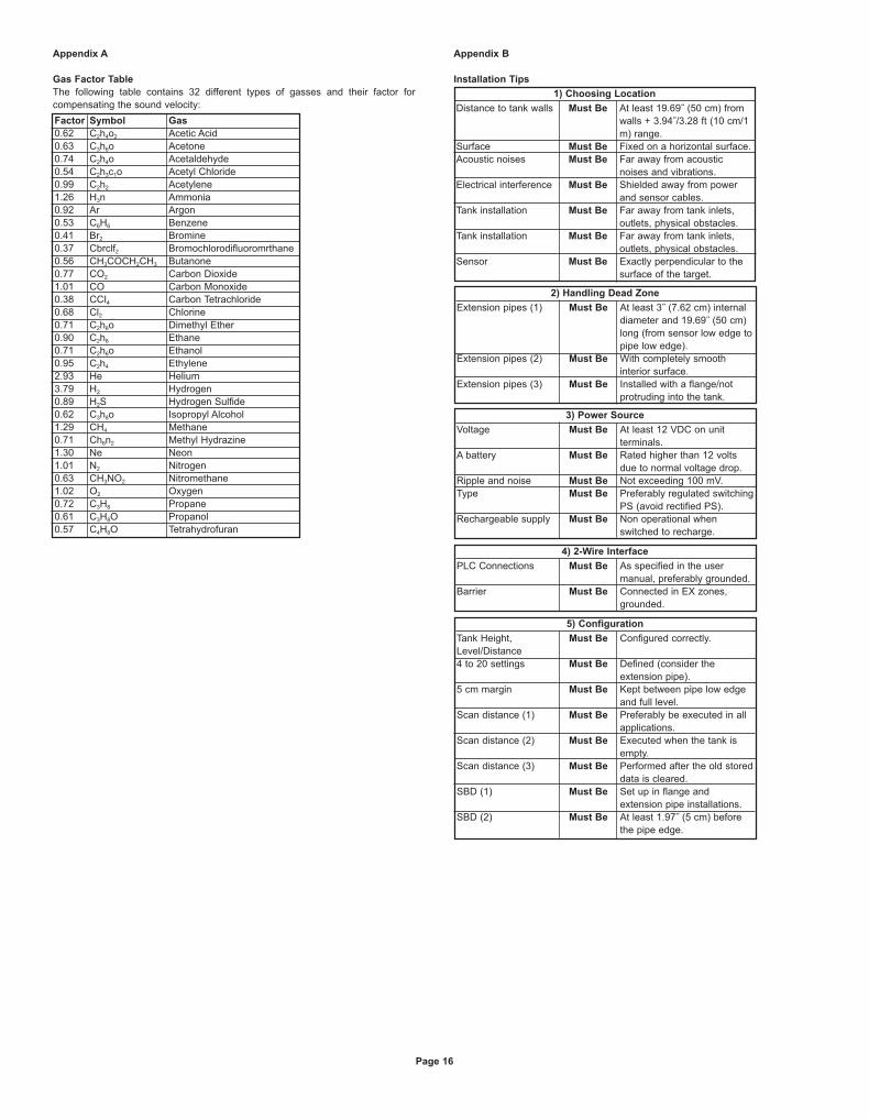
Appendix A
Gas Factor Table
The following table contains 32 different types of gasses and their factor for
compensating the sound velocity:
Appendix B
Installation Tips
Page 16
Distance to tank walls
Surface
Acoustic noises
Electrical interference
Tank installation
Tank installation
Sensor
Must Be
Must Be
Must Be
Must Be
Must Be
Must Be
Must Be
At least 19.69˝ (50 cm) from
walls + 3.94˝/3.28 ft (10 cm/1
m) range.
Fixed on a horizontal surface.
Far away from acoustic
noises and vibrations.
Shielded away from power
and sensor cables.
Far away from tank inlets,
outlets, physical obstacles.
Far away from tank inlets,
outlets, physical obstacles.
Exactly perpendicular to the
surface of the target.
1) Choosing Location
Extension pipes (1)
Extension pipes (2)
Extension pipes (3)
Must Be
Must Be
Must Be
At least 3˝ (7.62 cm) internal
diameter and 19.69˝ (50 cm)
long (from sensor low edge to
pipe low edge).
With completely smooth
interior surface.
Installed with a flange/not
protruding into the tank.
2) Handling Dead Zone
Voltage
A battery
Ripple and noise
Type
Rechargeable supply
Must Be
Must Be
Must Be
Must Be
Must Be
At least 12 VDC on unit
terminals.
Rated higher than 12 volts
due to normal voltage drop.
Not exceeding 100 mV.
Preferably regulated switching
PS (avoid rectified PS).
Non operational when
switched to recharge.
3) Power Source
PLC Connections
Barrier
Must Be
Must Be
As specified in the user
manual, preferably grounded.
Connected in EX zones,
grounded.
4) 2-Wire Interface
Tank Height,
Level/Distance
4 to 20 settings
5 cm margin
Scan distance (1)
Scan distance (2)
Scan distance (3)
SBD (1)
SBD (2)
Must Be
Must Be
Must Be
Must Be
Must Be
Must Be
Must Be
Must Be
Configured correctly.
Defined (consider the
extension pipe).
Kept between pipe low edge
and full level.
Preferably be executed in all
applications.
Executed when the tank is
empty.
Performed after the old stored
data is cleared.
Set up in flange and
extension pipe installations.
At least 1.97˝ (5 cm) before
the pipe edge.
5) Configuration
Factor
0.62
0.63
0.74
0.54
0.99
1.26
0.92
0.53
0.41
0.37
0.56
0.77
1.01
0.38
0.68
0.71
0.90
0.71
0.95
2.93
3.79
0.89
0.62
1.29
0.71
1.30
1.01
0.63
1.02
0.72
0.61
0.57
Symbol
C2h4o2
C3h6o
C2h4o
C2h3c1o
C2h2
H3n
Ar
C6H6
Br2
Cbrclf2
CH3COCH2CH3
CO2
CO
CCI4
Cl2
C2h6o
C2h6
C2h6o
C2h4
He
H2
H2S
C3h8o
CH4
Ch6n2
Ne
N2
CH3NO2
O2
C3H8
C3H8O
C4H8O
Gas
Acetic Acid
Acetone
Acetaldehyde
Acetyl Chloride
Acetylene
Ammonia
Argon
Benzene
Bromine
Bromochlorodifluoromrthane
Butanone
Carbon Dioxide
Carbon Monoxide
Carbon Tetrachloride
Chlorine
Dimethyl Ether
Ethane
Ethanol
Ethylene
Helium
Hydrogen
Hydrogen Sulfide
Isopropyl Alcohol
Methane
Methyl Hydrazine
Neon
Nitrogen
Nitromethane
Oxygen
Propane
Propanol
Tetrahydrofuran
L-UL:SSS-1000 12/15/10 9:11 AM Page 17
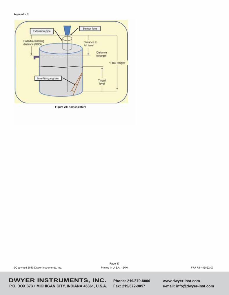
Appendix C
Page 17
Figure 29: Nomenclature
©Copyright 2010 Dwyer Instruments, Inc. Printed in U.S.A. 12/10 FR# R4-443852-00
DWYER INSTRUMENTS, INC. Phone: 219/879-8000 www.dwyer-inst.com
P.O. BOX 373 • MICHIGAN CITY, INDIANA 46361, U.S.A. Fax: 219/872-9057 e-mail: [email protected]
L-UL:SSS-1000 12/15/10 9:11 AM Page 18