Embed Size (px)
Citation preview
Dynamic Analysis and Stability of the Load Frequency Control in Two Area Power System with Steam Turbine
Ghazanfar Shahgholian Department of Electrical
Engineering - Islamic Azad University Najaf Abad Branch
Esfahan, Iran [email protected]
Serareh Yazdekhasti Member of Young Researcher Club
Islamic Azad University – Najaf Abad Branch Esfahan, Iran
Pegah Shafaghi Department of Electrical
Engineering - Islamic Azad University Najaf Abad Branch
Esfahan, Iran [email protected]
Abstract— The aim of this paper is to model, analysis and simulation of load frequency control in two area power system and parameters variation effects. State equations of a LFC in two area power system for a steam turbine are proposed. Then by examining some factors such as tie-line stiffness, turbine time constant, inertia constant and damping factor, the frequency control methods and influence of a small load variation are discussed. Finally, the steady state change in frequency in different cases using Matlab is calculate and compared.
Keywords-load frequency control; dynamic analysis; integral controller.
I. INTRODUCTION The objective of modern power systems is to transfer
enough high quality real and reactive power produced by generating units to customers through transmission lines. In an interconnected power system, the synchronous generators should rotate at the same speed and power flows over tie-lines should remain constant under normal operating conditions. Load frequency control (LFC) is a very importa-nt in power system operation and control for supplying sufficient and reliable electrical power with good quality, especially interconnected power systems [1-2]. Automatic generation control (AGC) or LFC is the mechanism by which the energy balance is maintained. The following summarizes the basic AGC objectives for an interconnected power system [3-4]: 1. Regulating system frequency error to zero and keep the system frequency in its scheduled value 2. Maintain accurate real time 3. Any area in need of power during emergency should be assisted from other areas. 4. Maintain net interchange power equal to scheduled values 5. Minimize equipment wear
Each of two areas as shown in Fig. 1 including steam turbines contains governor, reheated stage of steam turbine and generation rate constraints [5]. The tie line power flow appears as a load increase in one area and a load decrease in the other area, depending on the direction of the flow. When a load change occurs in any area, a new steady state operati-on can be obtained only after the power output of every
turbine generating unit in the interconnected system reaches a constant value. In a power system consisting of intercon-nected areas, each area agrees to export or import a sc-heduled amount of power through transmission line interco-nnections to its neighboring areas. The LFC problems are characterized by stochastic disturbances, variable and unpredictable inputs, unknown parameters, nonlinearity and changes in plant transfer function. In order to improve LFC system problem, advance control techniques such as ada-ptive control [6], variable structure control [7], fuzzy PI co-ntroller [8, 9] and linear feedback optimal control [10], have been proposed. A completely decentralized controller for the LFC operated as a load following service proposes in [11]. An application of layered artificial neural network controller to study LFC problem in three-area interconn-ected power system that two areas include steam turbines and the other area includes a hydro turbine is shown in [12]. A fuzzy control scheme for a LFC in two-area power system, which accepts change in frequency and changes in generator output as its inputs and generates a required control signal, is proposed in [13].
Figure 1. Two connected area
The aim of this paper is to model, analysis and simulation of load frequency control in two area power system and parameters variation effects. The remainder part of this paper is organized as follows. In section II the plant model and equation of the system is described. The various transfer functions in section III are studied. Finally, the steady state change in frequency in different cases using Matlab are calculate and compared in section IV and discussed in section V.
2009 Second International Conference on Computer and Electrical Engineering
978-0-7695-3925-6/09 $26.00 © 2009 IEEE
DOI 10.1109/ICCEE.2009.95
30
2009 Second International Conference on Computer and Electrical Engineering
978-0-7695-3925-6/09 $26.00 © 2009 IEEE
DOI 10.1109/ICCEE.2009.95
30
II. SYAYTEM EQUATION In this section, an analytical approach is given for the
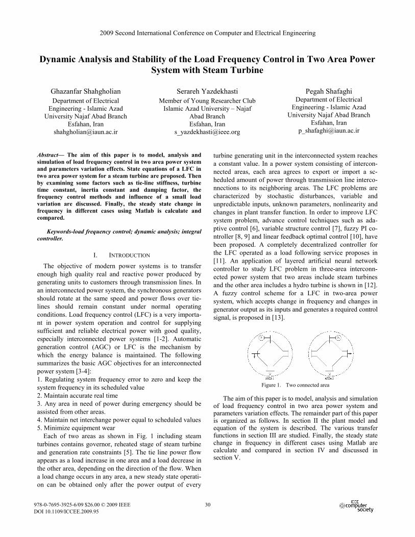
investigation of two area power system dynamics. The LFC system consists of four parts: turbine, governor, electrical system and controller. A block diagram representation for the two area system with LFC containing integral controller is shown in Fig. 2, where GT(s), GG(s) and GP(s) denote the transfer functions of turbine, governor and electrical systems respectively. Changes in load are accompanied by changes in system frequency, generation and tie line power flows. The system frequency and tie line power flows must be kept within specified limits. The inputs to the system are changes to the electric load ΔPD1 and ΔPD2 in each area. Quantities of interest are the mechanical power output of the turbine, ΔPT1 and ΔPT2, changes to the plant set point, ΔPC1 and ΔPC2, output change of governor, ΔPG1 and ΔPG2, and the system frequency increment, ΔPF1 and ΔPF2, of the each area system. Other quantity of interest is the deviation of tie line power flow out of the area from the scheduled power flow, ΔPTIE. It is known that LFC systems include an integral control as secondary controller, in conventional control configurations.
Figure 2. Two area system with LFC with integral controller
In practice the adjustment of ΔPC1 and ΔPC2 is done automatically by the tie line bias control or secondary control. Each area supplies its user pool and allows electric power to flow between areas. The control error for each area consists of a linear combination of frequency error and tie-line error [9]. The area control error (ACE) must be kept close to zero in each control area. The ACE is used as the input of the PI controller of LFC, while the output is the raise/lower signal (ΔPC) sent to generating units to adjust their generated power to meet the demand [14]. The ACE for a two area system is:
NNTIE1N
N fBP)1(ACE Δ+Δ−= + N=1, 2 (1)
where N is number of area and BN is frequency bias setting. The BN should be high enough such that each area adequately contributes to frequency control. The choosing BN equal to the area frequency response characteristic (β), gives satisfactory performance of interconnected system. The value of β varies according to electric load characterist-ic, governor performance and speed regulation settings [15]. If speed regulation factor and damping factor system for an each area is represented by RN and DN respectively, then the βN is:
NNN R
1D +=β (2)
The value of ΔfN in (1) represents the amount of frequency variation, which can be calculated as below:
oN fff −=Δ (3)
where fo is the nominal frequency and f is the operating frequency. The frequency bias BN determines the amount of interaction during a disturbance in the neighboring areas. The BN should be high enough such that each area adequately contributes to frequency control. The ACEs are used as actuating signals to activate changes in the reference power set points, and when steady state is reached, ΔPTIE and ΔfN is returned to zero and ACE1=ACE2. Sate equation of two area system with controller and without reheat with nine variables:
T1C1G1T2TIE1C1G1T1 ]PPPfPPPPf[X ΔΔΔΔΔΔΔΔΔ= (4)
and two inputs:
T2D1D ]PP[U ΔΔ= (5)
are obtained. The equation systems for N=1, 2 are:
NNGN
GNCN
GN
GNGN
GNGN f
RTK
PTK
PT
1Pdtd Δ+Δ+Δ−=Δ (6)
DNPN
PNTIE
PN
PNNN
PNN P
TK
PTK
)1(fT
1fdtd Δ−Δ−+Δ−=Δ
TNPN
PN PTK
Δ+ (7)
GNTN
TNTN
TNTN P
TK
PT
1Pdtd Δ+Δ−=Δ (8)
TIEINN
NNINCN PK)1(fBKPdtd Δ−+Δ−=Δ (9)
3131
where KTN and TTN are steady state gain and time constant of turbine, KGN and TGN are gain and time constant of generator, KIN is integration constant. The steady state gain (KPN) and time constant of electrical system (TPN) are:
NPN D
1K = (10)
N
NPN D
H2T = (11)
where HN is inertia constant. The equation of tie-line power is:
)ff(TPdtd
21TIE Δ−Δ=Δ (12)
where T is tie-line stiffness or the slope of the power angle curve at the initial operating angle. If T=0, tie-line is open and for T>0, tie-line is in operation. The LFC process also controls the power flow on the tie line.
III. DYNAMIC ANANLYSIS
LFC is a fundamental method to stabilize system frequen-cies and tie-line power flows in an interconnected system [16]. Without LFC, the frequency of power supply may not be able to be controlled within the required limit band, therefore it is very important that when a fault occurs in the control loop. In this section various transfer functions describing the step response of the frequency variation following step change in load each area. The transfer functions are studied using Matlab and the step response verified by time domain simulation. Key parameters of the two area systems are listed in Table I.
TABLE I. MAIN PARAMETERS FOR TWO AREA POWER SYSTEM
Parameter Area 1 Area 2 HN 5 4 DN 0.6 0.9 TTN 0.5 0.6 KTN 1 1 TGN 0.2 0.3 KGN 1 1 RN 0.05 0.06 KIN 0.3 0.3 T 2
IV. PARAMETERS CHANGE EFFECTS AND SIMULATION
RESULTS The role of LFC has the controlled role in the frequency
of the standard in perceiving the change of the load to the load that changes every time, and operating kinds of
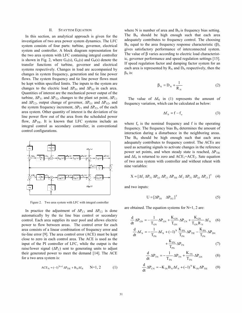
governor with thermal power and the hydroelectric power plant with kinds of governor. The comparison of the dynam-ic response of first area frequency deviation with integral control for a step change in the load in area 1 in terms of parameters changes of first area shown in Figs. 3, 4 and 5.
Figure 3. Frequency deviation in area 1 in terms of inertia constant changes of first area
(a) Area 1
(b) Area 2
Figure 4. Frequency deviation in terms of integration constant changes of first area
Figure 5. Frequency deviation in terms of turbine time constant of first area
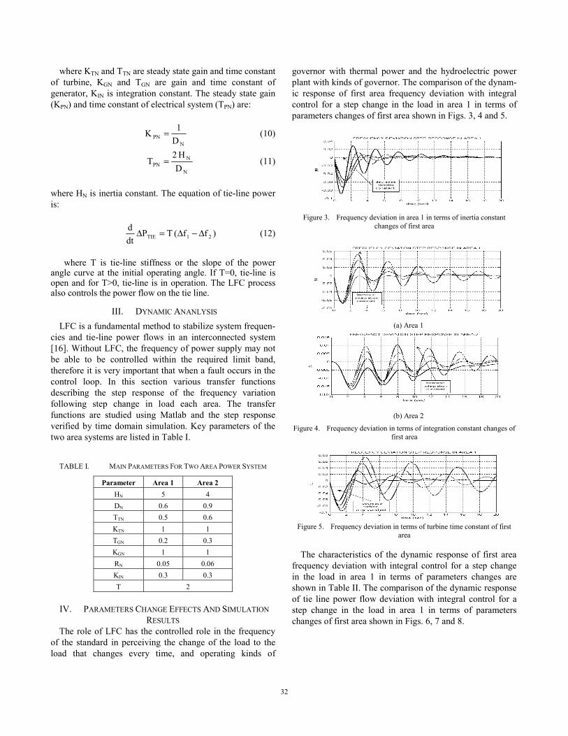
The characteristics of the dynamic response of first area frequency deviation with integral control for a step change in the load in area 1 in terms of parameters changes are shown in Table II. The comparison of the dynamic response of tie line power flow deviation with integral control for a step change in the load in area 1 in terms of parameters changes of first area shown in Figs. 6, 7 and 8.
3232
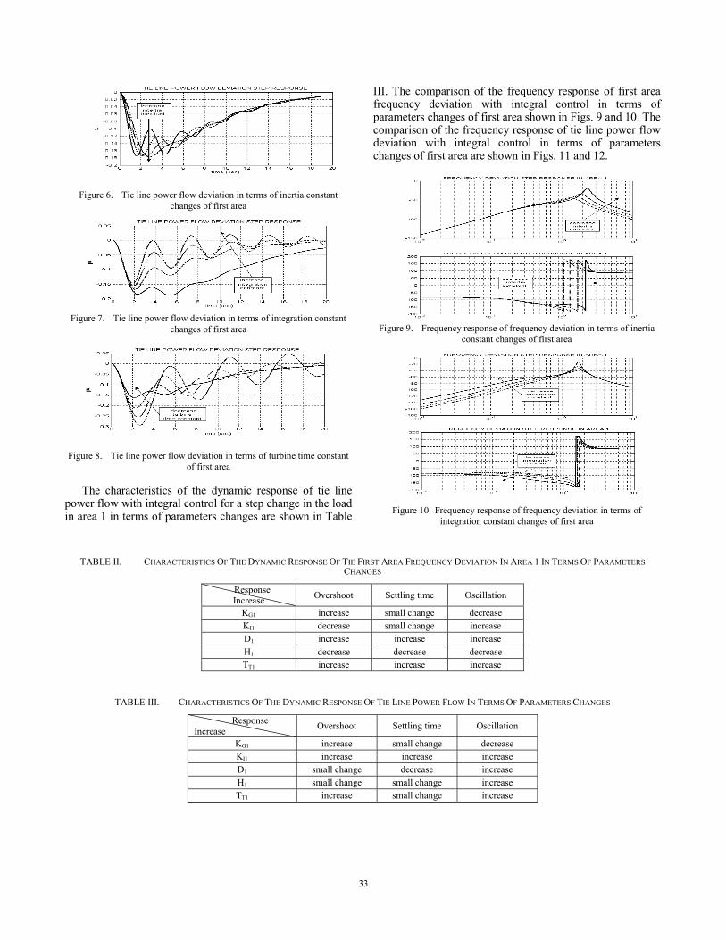
Figure 6. Tie line power flow deviation in terms of inertia constant changes of first area
Figure 7. Tie line power flow deviation in terms of integration constant changes of first area
Figure 8. Tie line power flow deviation in terms of turbine time constant of first area
The characteristics of the dynamic response of tie line power flow with integral control for a step change in the load in area 1 in terms of parameters changes are shown in Table
III. The comparison of the frequency response of first area frequency deviation with integral control in terms of parameters changes of first area shown in Figs. 9 and 10. The comparison of the frequency response of tie line power flow deviation with integral control in terms of parameters changes of first area are shown in Figs. 11 and 12.
Figure 9. Frequency response of frequency deviation in terms of inertia constant changes of first area
Figure 10. Frequency response of frequency deviation in terms of integration constant changes of first area
TABLE II. CHARACTERISTICS OF THE DYNAMIC RESPONSE OF TIE FIRST AREA FREQUENCY DEVIATION IN AREA 1 IN TERMS OF PARAMETERS CHANGES
Response Increase Overshoot Settling time Oscillation
KG1 increase small change decrease KI1 decrease small change increase D1 increase increase increase H1 decrease decrease decrease TT1 increase increase increase
TABLE III. CHARACTERISTICS OF THE DYNAMIC RESPONSE OF TIE LINE POWER FLOW IN TERMS OF PARAMETERS CHANGES
Response Increase Overshoot Settling time Oscillation
KG1 increase small change decrease KI1 increase increase increase D1 small change decrease increase H1 small change small change increase TT1 increase small change increase
3333
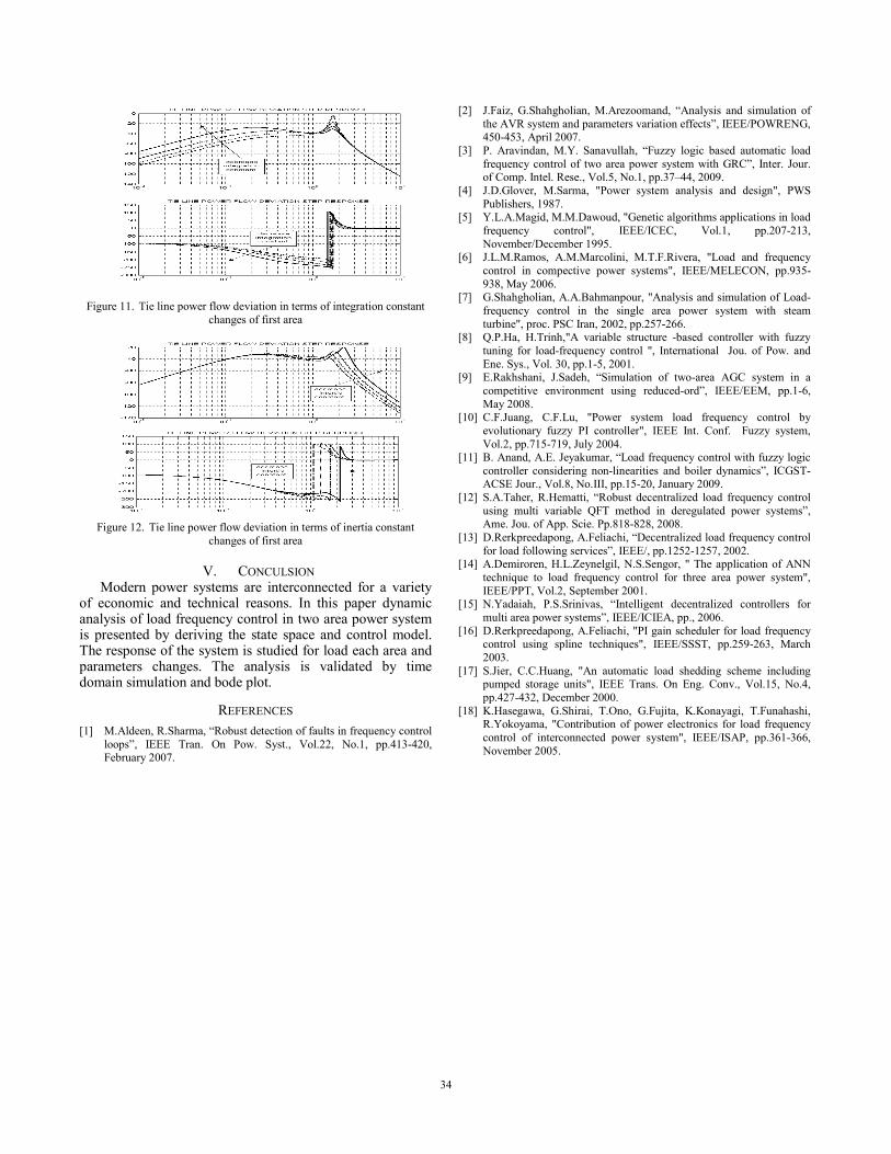
Figure 11. Tie line power flow deviation in terms of integration constant changes of first area
Figure 12. Tie line power flow deviation in terms of inertia constant changes of first area
V. CONCULSION Modern power systems are interconnected for a variety
of economic and technical reasons. In this paper dynamic analysis of load frequency control in two area power system is presented by deriving the state space and control model. The response of the system is studied for load each area and parameters changes. The analysis is validated by time domain simulation and bode plot.
REFERENCES [1] M.Aldeen, R.Sharma, “Robust detection of faults in frequency control
loops”, IEEE Tran. On Pow. Syst., Vol.22, No.1, pp.413-420, February 2007.
[2] J.Faiz, G.Shahgholian, M.Arezoomand, “Analysis and simulation of the AVR system and parameters variation effects”, IEEE/POWRENG, 450-453, April 2007.
[3] P. Aravindan, M.Y. Sanavullah, “Fuzzy logic based automatic load frequency control of two area power system with GRC”, Inter. Jour. of Comp. Intel. Rese., Vol.5, No.1, pp.37–44, 2009.
[4] J.D.Glover, M.Sarma, "Power system analysis and design", PWS Publishers, 1987.
[5] Y.L.A.Magid, M.M.Dawoud, "Genetic algorithms applications in load frequency control", IEEE/ICEC, Vol.1, pp.207-213, November/December 1995.
[6] J.L.M.Ramos, A.M.Marcolini, M.T.F.Rivera, "Load and frequency control in compective power systems", IEEE/MELECON, pp.935-938, May 2006.
[7] G.Shahgholian, A.A.Bahmanpour, "Analysis and simulation of Load- frequency control in the single area power system with steam turbine", proc. PSC Iran, 2002, pp.257-266.
[8] Q.P.Ha, H.Trinh,"A variable structure -based controller with fuzzy tuning for load-frequency control ", International Jou. of Pow. and Ene. Sys., Vol. 30, pp.1-5, 2001.
[9] E.Rakhshani, J.Sadeh, “Simulation of two-area AGC system in a competitive environment using reduced-ord”, IEEE/EEM, pp.1-6, May 2008.
[10] C.F.Juang, C.F.Lu, "Power system load frequency control by evolutionary fuzzy PI controller", IEEE Int. Conf. Fuzzy system, Vol.2, pp.715-719, July 2004.
[11] B. Anand, A.E. Jeyakumar, “Load frequency control with fuzzy logic controller considering non-linearities and boiler dynamics”, ICGST-ACSE Jour., Vol.8, No.III, pp.15-20, January 2009.
[12] S.A.Taher, R.Hematti, “Robust decentralized load frequency control using multi variable QFT method in deregulated power systems”, Ame. Jou. of App. Scie. Pp.818-828, 2008.
[13] D.Rerkpreedapong, A.Feliachi, “Decentralized load frequency control for load following services”, IEEE/, pp.1252-1257, 2002.
[14] A.Demiroren, H.L.Zeynelgil, N.S.Sengor, " The application of ANN technique to load frequency control for three area power system", IEEE/PPT, Vol.2, September 2001.
[15] N.Yadaiah, P.S.Srinivas, “Intelligent decentralized controllers for multi area power systems”, IEEE/ICIEA, pp., 2006.
[16] D.Rerkpreedapong, A.Feliachi, "PI gain scheduler for load frequency control using spline techniques", IEEE/SSST, pp.259-263, March 2003.
[17] S.Jier, C.C.Huang, "An automatic load shedding scheme including pumped storage units", IEEE Trans. On Eng. Conv., Vol.15, No.4, pp.427-432, December 2000.
[18] K.Hasegawa, G.Shirai, T.Ono, G.Fujita, K.Konayagi, T.Funahashi, R.Yokoyama, "Contribution of power electronics for load frequency control of interconnected power system", IEEE/ISAP, pp.361-366, November 2005.
3434