Embed Size (px)
DESCRIPTION
E & EP Notes Outcome 3 National Dip/cert Yr 1
Citation preview
OUTCOME 2. Understand the concepts ofcapacitance and determine capacitance valuesin DC circuits.
Electrostatics.
Electrostatics is about quantity of charge on a material,and not passing through it. This includes staticelectricity and components known as capacitors.
Static-Electricity.
This is the charge we can produce by rubbing aballoon etc. and allows us to stick them on the ceiling orpick up bits of paper etc. In this form the engineeringapplications are a bit limited. However, the mostpractical use is in photocopiers and laser printers, herea static charge is placed on a rotating drum. UV light isshone on to the drum or in the case of a printer on tothe paper. This charge allows the ink in powder form tostick to the charged areas, and with heating, pressureetc. produces the image on the paper. Outside of thisuse their is little use in industry for static-electricty, andit is more of a problem as it causes things to sticktogether.
Capacitors.
Capacitors are components used to hold a chargeor quantity of electricity. Charge is measured inCoulombs which in turn is a quantity of electrons.Capacitors use plates insulated from each other to storecharge in the form of electrons. The unit for capacitance
National Dip/Cert/Award E & EP
60
is the FARAD [F], 1F is a very large value ofcapacitance and therefore it is more common to use :
pico farad F 1012 micro farad F 106
milli farad mF 103
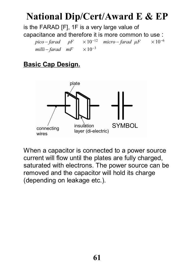
Basic Cap Design.
When a capacitor is connected to a power sourcecurrent will flow until the plates are fully charged,saturated with electrons. The power source can beremoved and the capacitor will hold its charge(depending on leakage etc.).
National Dip/Cert/Award E & EP
61
SYMBOLconnectingwires
plate
insulationlayer (di-electric)
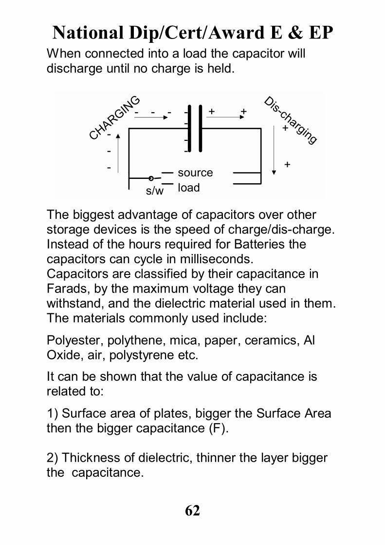
When connected into a load the capacitor willdischarge until no charge is held.
The biggest advantage of capacitors over otherstorage devices is the speed of charge/dis-charge.Instead of the hours required for Batteries thecapacitors can cycle in milliseconds.Capacitors are classified by their capacitance inFarads, by the maximum voltage they canwithstand, and the dielectric material used in them.The materials commonly used include:
Polyester, polythene, mica, paper, ceramics, AlOxide, air, polystyrene etc.
It can be shown that the value of capacitance isrelated to:
1) Surface area of plates, bigger the Surface Areathen the bigger capacitance (F).
2) Thickness of dielectric, thinner the layer biggerthe capacitance.
National Dip/Cert/Award E & EP
62
s/w
sourceload
---
- - - ----
CHARGING
+ ++
+
Dis-charging
However, as the thickness of the dielectricdecreases then its ability to withstand high voltagesdecreases. This is due to the potential differencebeing the pushing force of electricity. The capacitorwill start to leak electrons through the di-elecrtric,this in turn can cause local heating and total failureof the component. Therefore a capacitor has amaximum working voltage based on the materialand its thickness used in the dielectric.
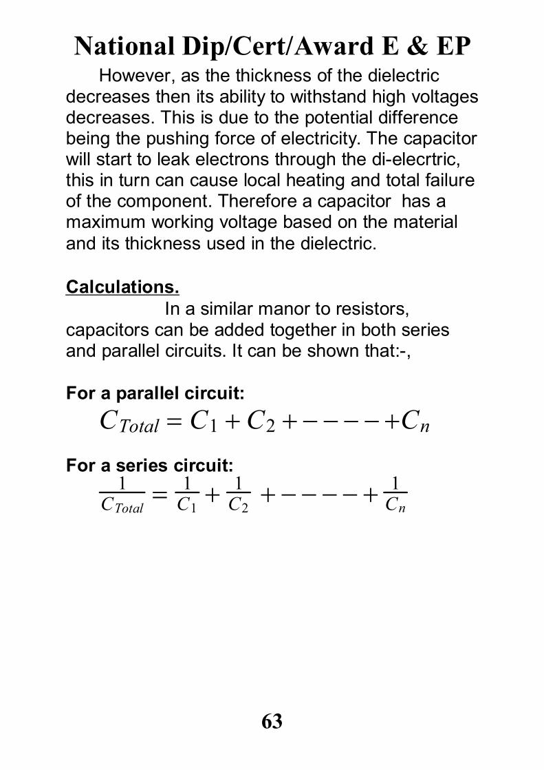
Calculations.In a similar manor to resistors,
capacitors can be added together in both seriesand parallel circuits. It can be shown that:-,
For a parallel circuit:
CTotal C1 C2 Cn
For a series circuit:1
CTotal 1
C1 1
C2 1
Cn
National Dip/Cert/Award E & EP
63
Questions 5.Complete the following questions using your notesand/or any source such as E & EP books etc.
1) What is the unit of capacitance.
2) What 3 values must be considered whenchoosing a capacitor.
3) What is the meaning of the prefixes: a) milli, b) micro, c) pico.
4) What letters are used to show the prefixes inquest 3.
5) What is the name given to the insulating layer ina capacitor.
National Dip/Cert/Award E & EP
64
6) List 5 materials commonly used as an insulatorin a capacitor.
7) What affect does increasing the size (surfacearea) of a capacitors plates have of itscapacitance.
8) One type of capacitor in common use is knownas, electrolytic capacitor. What is the dielectricused, and what must we as users be very carefulabout when putting these into circuits.
9) What is the symbol used for the capacitordescribed in Q8.
10) Give 3 applications of capacitors in everydayitems.
National Dip/Cert/Award E & EP
65
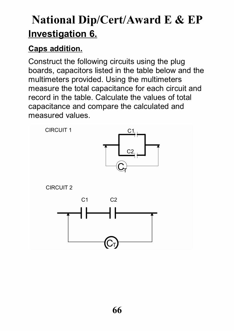
Investigation 6.
Caps addition.
Construct the following circuits using the plugboards, capacitors listed in the table below and themultimeters provided. Using the multimetersmeasure the total capacitance for each circuit andrecord in the table. Calculate the values of totalcapacitance and compare the calculated andmeasured values.
National Dip/Cert/Award E & EP
66
CT
C1CIRCUIT 1
CIRCUIT 2
C1 C2
CT
C2
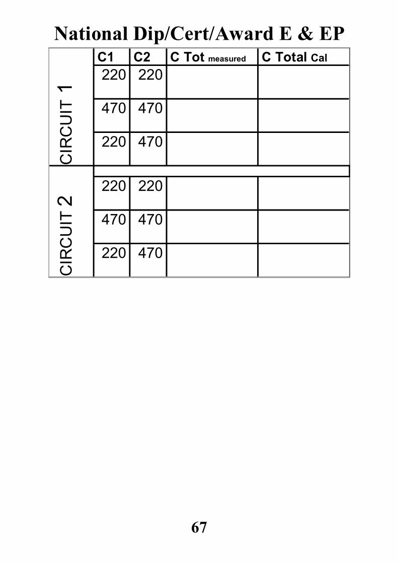
470220
470470
220220
CIR
CU
IT 2
470220
470470
220220C Total CalC Tot measuredC2C1
CIR
CU
IT 1
National Dip/Cert/Award E & EP
67
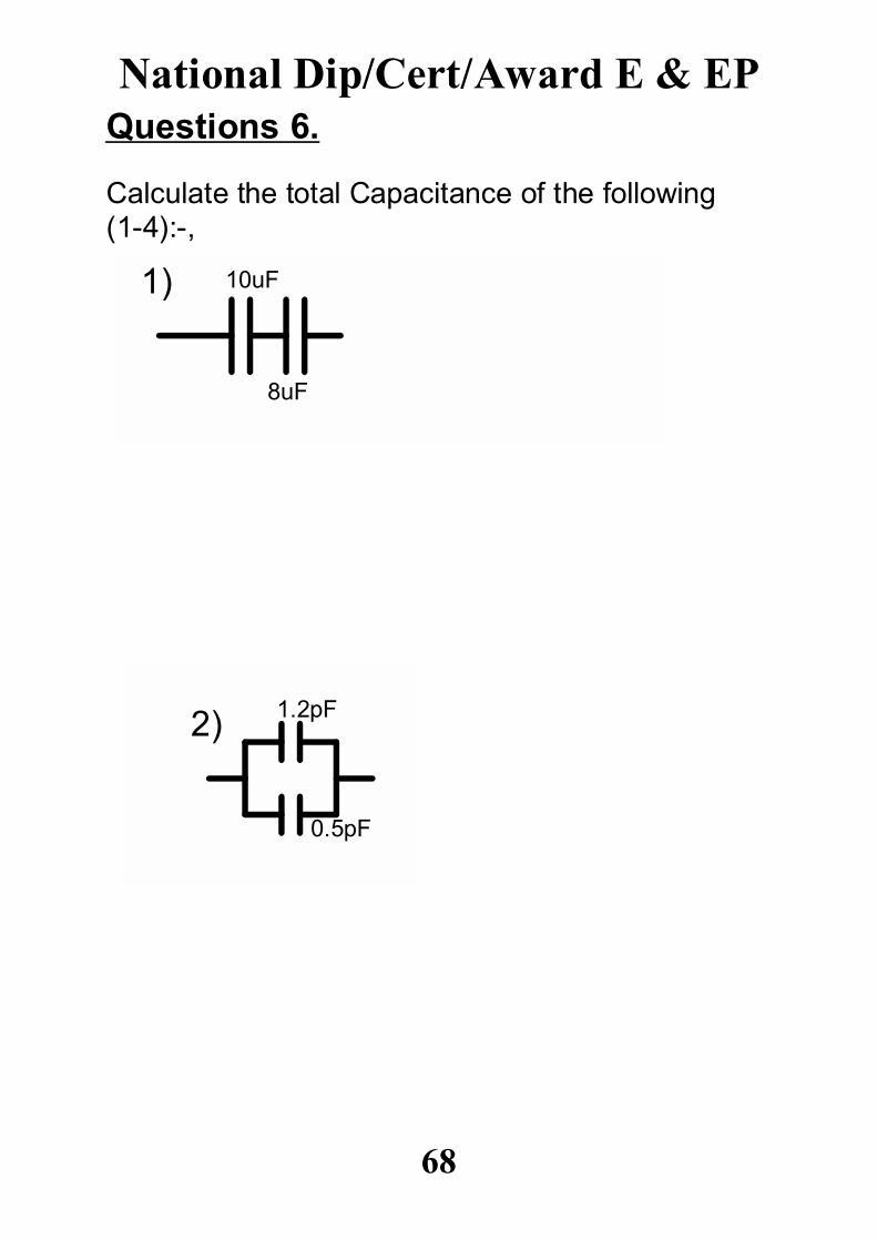
Questions 6.
Calculate the total Capacitance of the following(1-4):-,
National Dip/Cert/Award E & EP
68
1) 10uF
8uF
2) 1.2pF
0.5pF
National Dip/Cert/Award E & EP
69
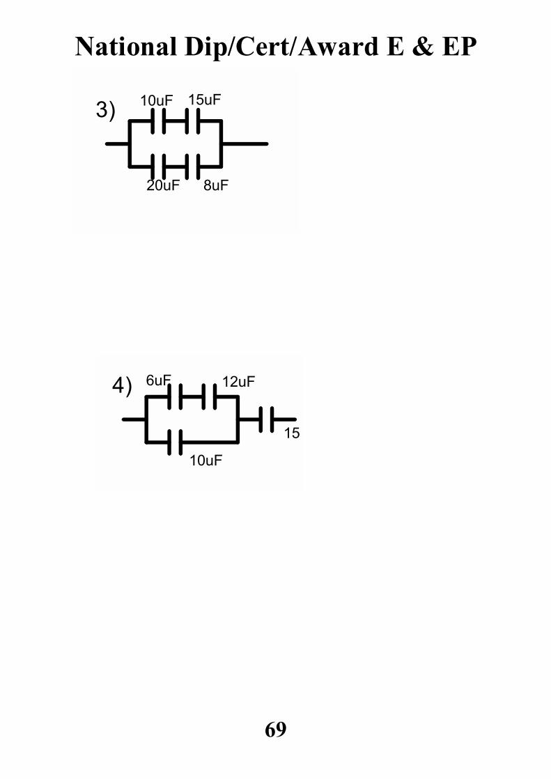
3) 10uF 15uF
20uF 8uF
4) 6uF 12uF
10uF
15uF
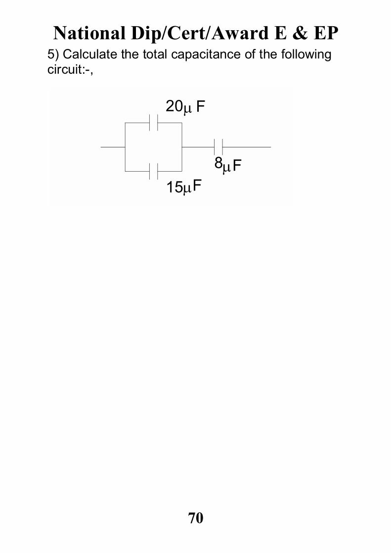
5) Calculate the total capacitance of the followingcircuit:-,
National Dip/Cert/Award E & EP
70
20
15
8
F
FF
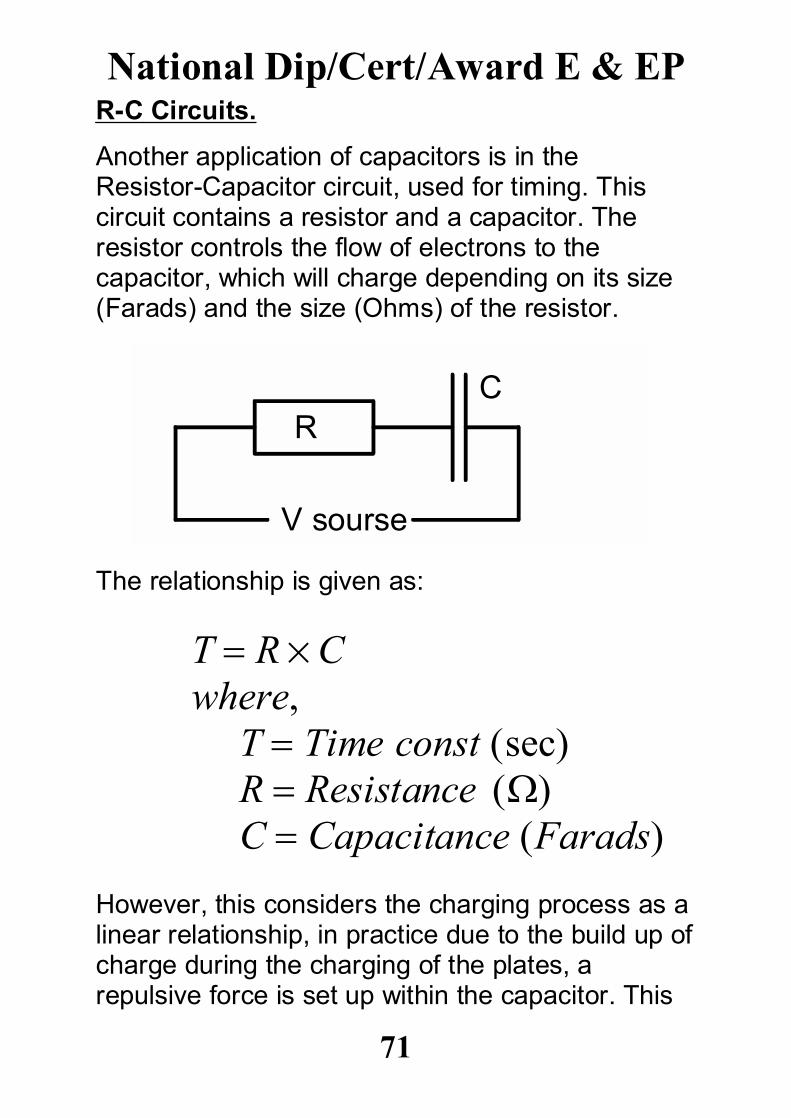
R-C Circuits.
Another application of capacitors is in theResistor-Capacitor circuit, used for timing. Thiscircuit contains a resistor and a capacitor. Theresistor controls the flow of electrons to thecapacitor, which will charge depending on its size(Farads) and the size (Ohms) of the resistor.
The relationship is given as:
T RCwhere,
T Time const secR Resistance C Capacitance Farads
However, this considers the charging process as alinear relationship, in practice due to the build up ofcharge during the charging of the plates, arepulsive force is set up within the capacitor. This
National Dip/Cert/Award E & EP
71
RC
V sourse
force reduces the flow of electrons to the platesand so increases the time taken for the capacitorto charge. This is a complex relationship that willnot be examined closely during this level of study.We therefore use a simplified form which states:-,
Time to reach Steady State 5T
where,T Time Const sec
Steady State is the term used for when acapacitor has reached a point where the incomingelectrons equals the leakage that is occurring. Thismeans the capacitor has reached a point ofequilibrium within the circuit. Under mostcircumstances this is approximately 90-97% of themaximum charge that the capacitor is expected tobe able to support.
National Dip/Cert/Award E & EP
72
Investigation 7.
OBJECTIVE.
Construct and test R-C circuits.
EQUIPMENT.
Multimeter, prototyping board, connecting wires,power supply, stop clock and a number ofcapacitors and resistors.
PROCEDURE.
a) Check values of Resistors and Capacitors to be used.
b) Use 10 or 12 volt setting on PSU.
c) Measure supply voltage and record.
d) Charge the circuit for 5 mins, recording the voltage every 10 seconds.
e) Plot these values on a graph as shown (volts vs.Time).
f) Calculate the time constant (T), and the timeto steady state (SS), plot these on the graph asshown.
g) Compare the values obtained.
National Dip/Cert/Award E & EP
73
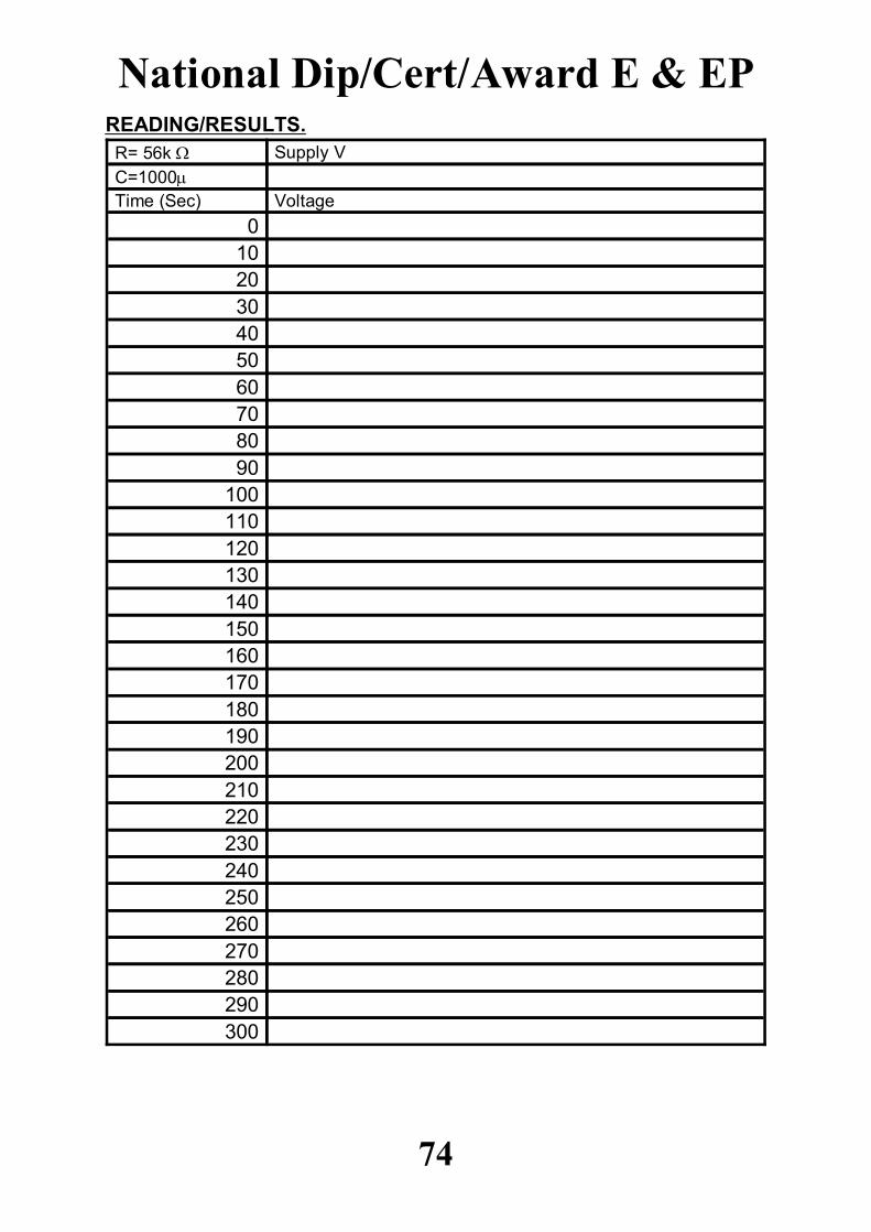
READING/RESULTS.
3002902802702602502402302202102001901801701601501401301201101009080706050403020100
VoltageTime (Sec)C=1000
Supply VR= 56k
National Dip/Cert/Award E & EP
74
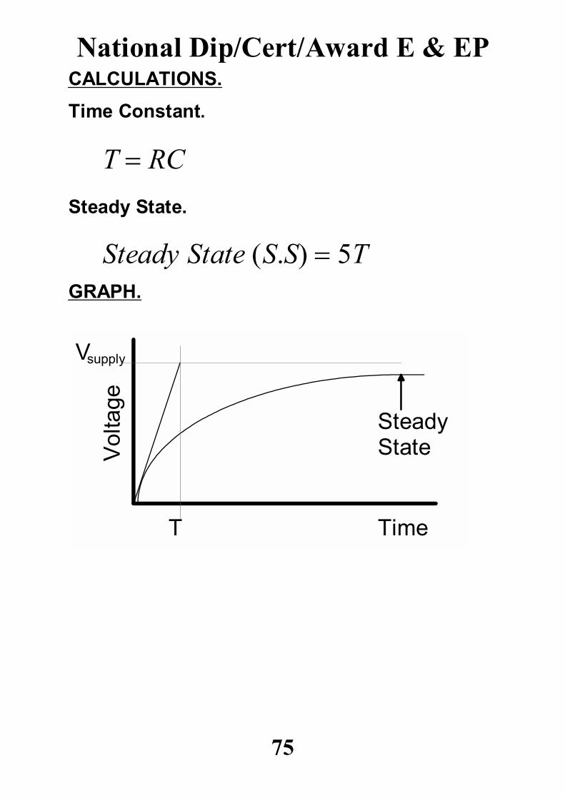
CALCULATIONS.
Time Constant.
T RC
Steady State.
Steady State S.S 5TGRAPH.
National Dip/Cert/Award E & EP
75
Time
Vol
tage
Vsupply
T
Steady State
National Dip/Cert/Award E & EP
76
V
time0
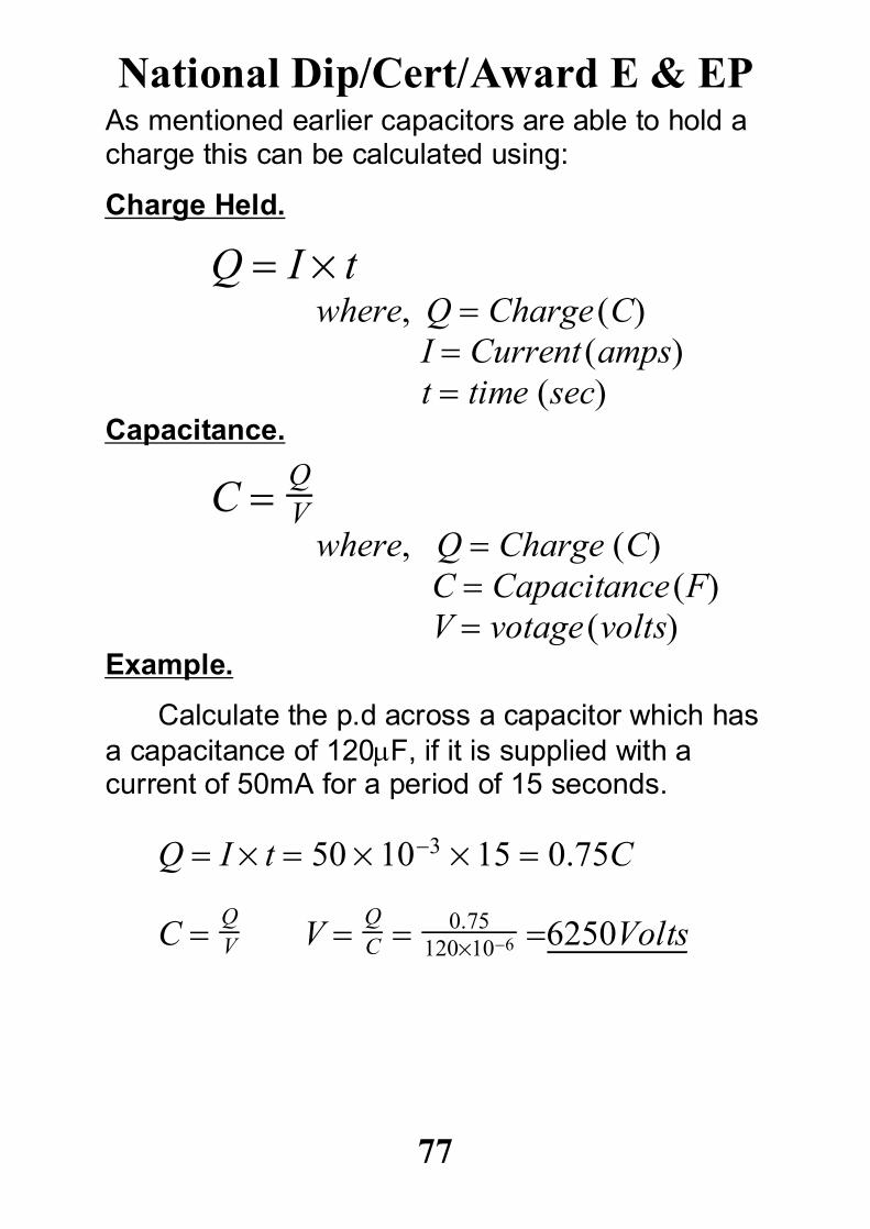
As mentioned earlier capacitors are able to hold acharge this can be calculated using:
Charge Held.
Q I twhere, Q Charge C
I Current ampst time sec
Capacitance.
C QV
where, Q Charge CC Capacitance F
V votage voltsExample.
Calculate the p.d across a capacitor which hasa capacitance of 120F, if it is supplied with acurrent of 50mA for a period of 15 seconds.
Q I t 50 103 15 0.75C
C QV V Q
C 0.75120106 6250Volts
National Dip/Cert/Award E & EP
77
Questions 7.1) Calculate the total capacitance of a circuitcontaining a 10F, and a 6F capacitor, if they areconnected in;
a) Series.
b) Parallel.
2) Calculate the quantity of charge stored on acapacitor, if its capacitance is 1000F, and it issupplied at 24 volts.
3) Calculate the time required for a charge of 5 Cto build up on a capacitor when the current flowingin the circuit is 400mA.
4) Calculate the size of capacitor (capacitance [F])required to give a p.d of 12 volts, at a current of200mA, for a period of 0.05seconds.
National Dip/Cert/Award E & EP
78
Investigation 8.
Dielectric Strength.
The maximum amount of field strength that amaterial being used as a dielectric can withstand iscalled he dielectric strength of the material.
E Vd
where,E dielectric strength V/m
V Voltage across plates vd thickness of dielectricm
During this investigation we are going to be using avoltage of up to 60,000 volts. This large voltagecan be very dangerous, all precautions should betaken such as the correct use of the equipmentand the interlocking system. At no time shouldanything be put between the electrodes that is nota test specimen The test should be carried outusing the AUTO system, and the max. V shouldnot be overridden.
National Dip/Cert/Award E & EP
79
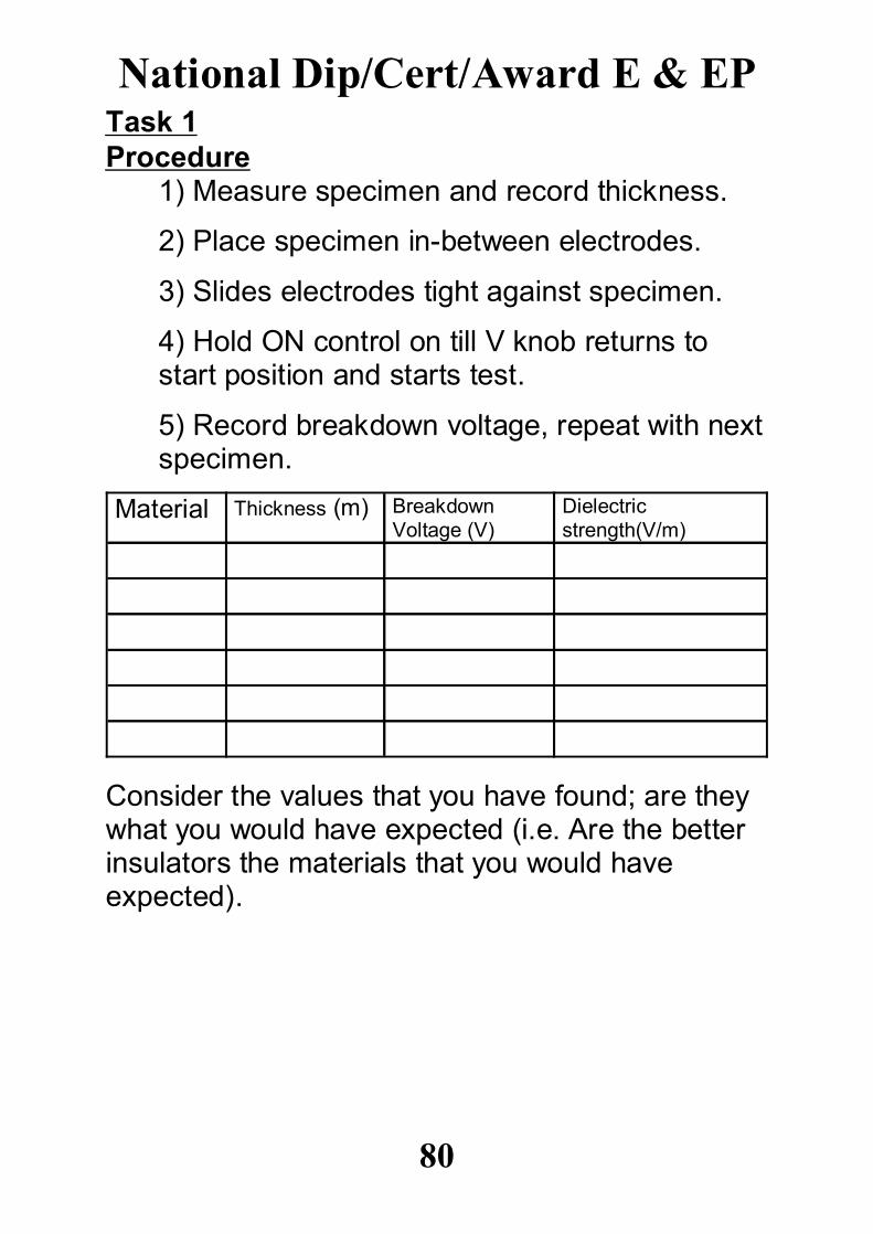
Task 1Procedure
1) Measure specimen and record thickness.
2) Place specimen in-between electrodes.
3) Slides electrodes tight against specimen.
4) Hold ON control on till V knob returns to start position and starts test.
5) Record breakdown voltage, repeat with nextspecimen.
Dielectricstrength(V/m)
BreakdownVoltage (V)
Thickness (m)Material
Consider the values that you have found; are theywhat you would have expected (i.e. Are the betterinsulators the materials that you would haveexpected).
National Dip/Cert/Award E & EP
80
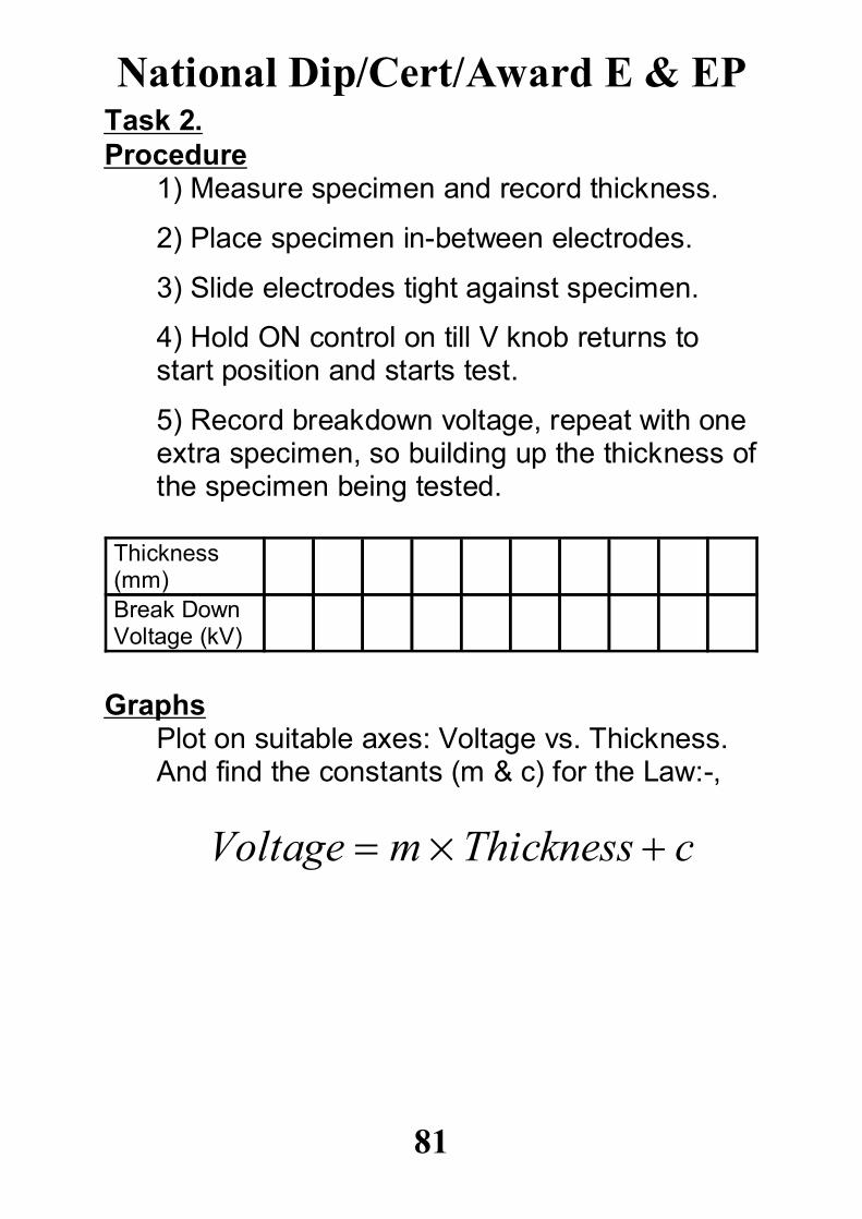
Task 2.Procedure
1) Measure specimen and record thickness.
2) Place specimen in-between electrodes.
3) Slide electrodes tight against specimen.
4) Hold ON control on till V knob returns to start position and starts test.
5) Record breakdown voltage, repeat with one extra specimen, so building up the thickness ofthe specimen being tested.
Break DownVoltage (kV)
Thickness(mm)
GraphsPlot on suitable axes: Voltage vs. Thickness.And find the constants (m & c) for the Law:-,
Voltage mThickness c
National Dip/Cert/Award E & EP
81
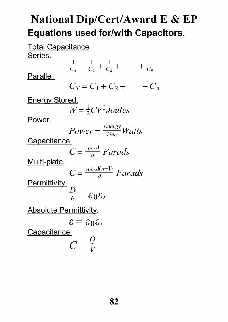
Equations used for/with Capacitors.Total CapacitanceSeries.
1CT
1C1 1
C2 1
Cn
Parallel.CT C1 C2 Cn
Energy Stored.W 1
2CV2JoulesPower.
Power EnergyTime Watts
Capacitance.C 0rA
d FaradsMulti-plate.
C 0rAn1d Farads
Permittivity.DE 0r
Absolute Permittivity.
0rCapacitance.
C QV
National Dip/Cert/Award E & EP
82
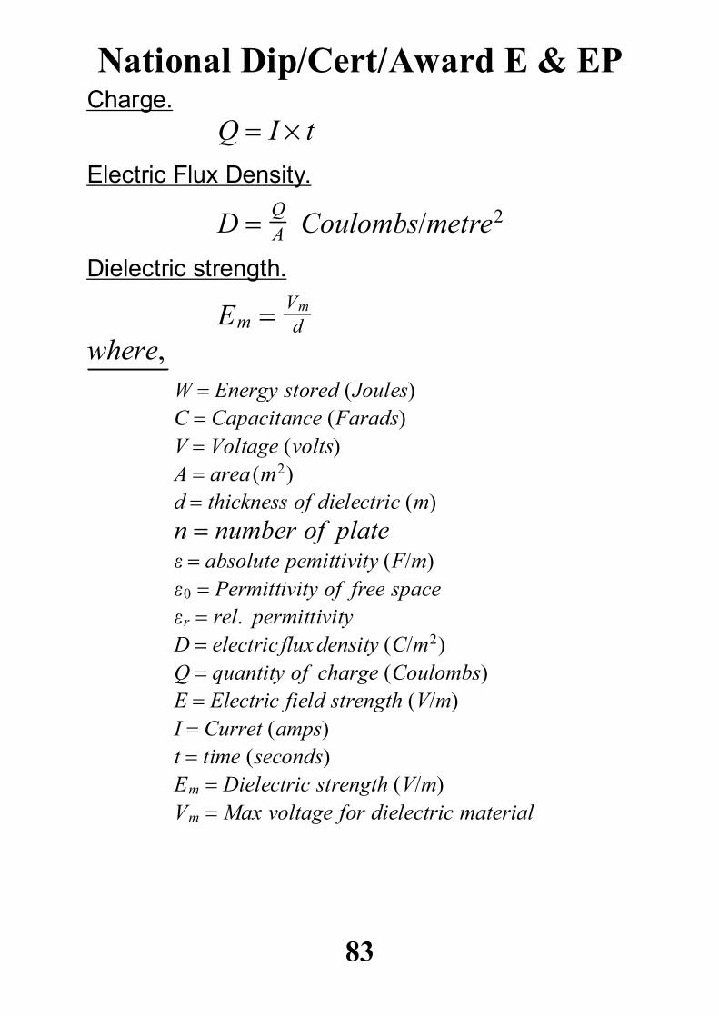
Charge.Q I t
Electric Flux Density.
D QA Coulombs/metre2
Dielectric strength.
Em Vmd
where,W Energy stored JoulesC Capacitance FaradsV Voltage voltsA area m2d thickness of dielectric mn number of plate absolute pemittivity F/m0 Permittivity of free spacer rel. permittivityD electricfluxdensity C/m2Q quantity of charge CoulombsE Electric field strength V/mI Curret ampst time secondsEm Dielectric strength V/mVm Max voltage for dielectric material
National Dip/Cert/Award E & EP
83
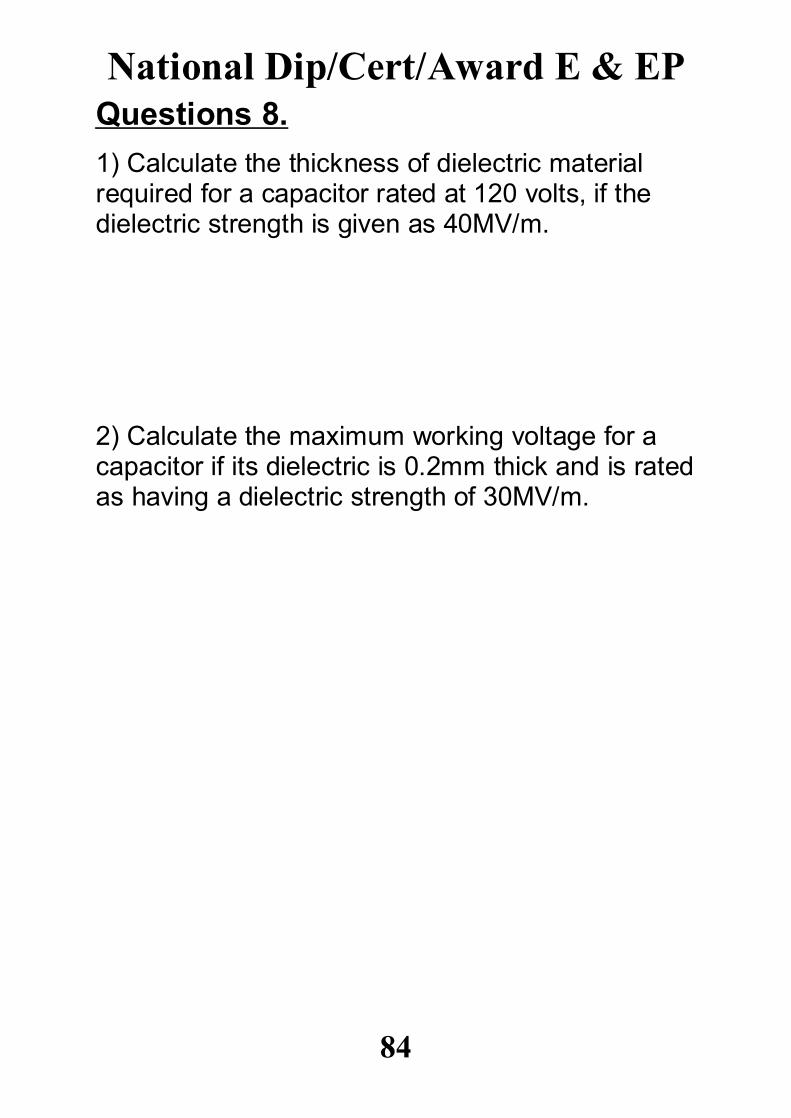
Questions 8.1) Calculate the thickness of dielectric materialrequired for a capacitor rated at 120 volts, if thedielectric strength is given as 40MV/m.
2) Calculate the maximum working voltage for acapacitor if its dielectric is 0.2mm thick and is ratedas having a dielectric strength of 30MV/m.
National Dip/Cert/Award E & EP
84
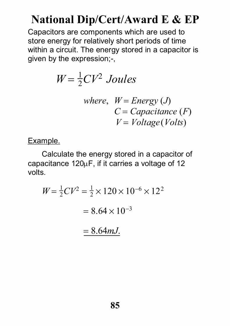
Capacitors are components which are used tostore energy for relatively short periods of timewithin a circuit. The energy stored in a capacitor isgiven by the expression;-,
W 12CV2 Joules
where, W Energy JC Capacitance FV Voltage Volts
Example.
Calculate the energy stored in a capacitor ofcapacitance 120F, if it carries a voltage of 12volts.
W 12CV2 1
2 120 106 122
8.64103
8.64mJ.
National Dip/Cert/Award E & EP
85
Questions 9.1) Calculate the energy stored in a capacitor if itcarries a voltage of 60 volts, and has acapacitance of 40F.
2) Calculate the size of capacitor (Capacitance),required to store 2 Joules of energy at a voltage of180 volts.
3) If a capacitor of capacitance 4000F isdischarged from 600 volts in a time of 10 ms,calculate the power dissipated by the capacitorduring the discharge.
National Dip/Cert/Award E & EP
86
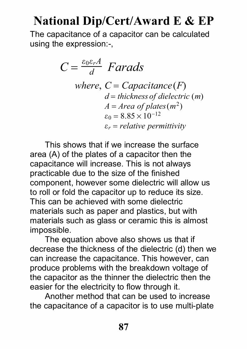
The capacitance of a capacitor can be calculatedusing the expression:-,
C 0rAd Farads
where, C Capacitance Fd thicknessof dielectric mA Area of plates m20 8.851012
r relative permittivity
This shows that if we increase the surfacearea (A) of the plates of a capacitor then thecapacitance will increase. This is not alwayspracticable due to the size of the finishedcomponent, however some dielectric will allow usto roll or fold the capacitor up to reduce its size.This can be achieved with some dielectricmaterials such as paper and plastics, but withmaterials such as glass or ceramic this is almostimpossible.
The equation above also shows us that ifdecrease the thickness of the dielectric (d) then wecan increase the capacitance. This however, canproduce problems with the breakdown voltage ofthe capacitor as the thinner the dielectric then theeasier for the electricity to flow through it.
Another method that can be used to increasethe capacitance of a capacitor is to use multi-plate
National Dip/Cert/Award E & EP
87
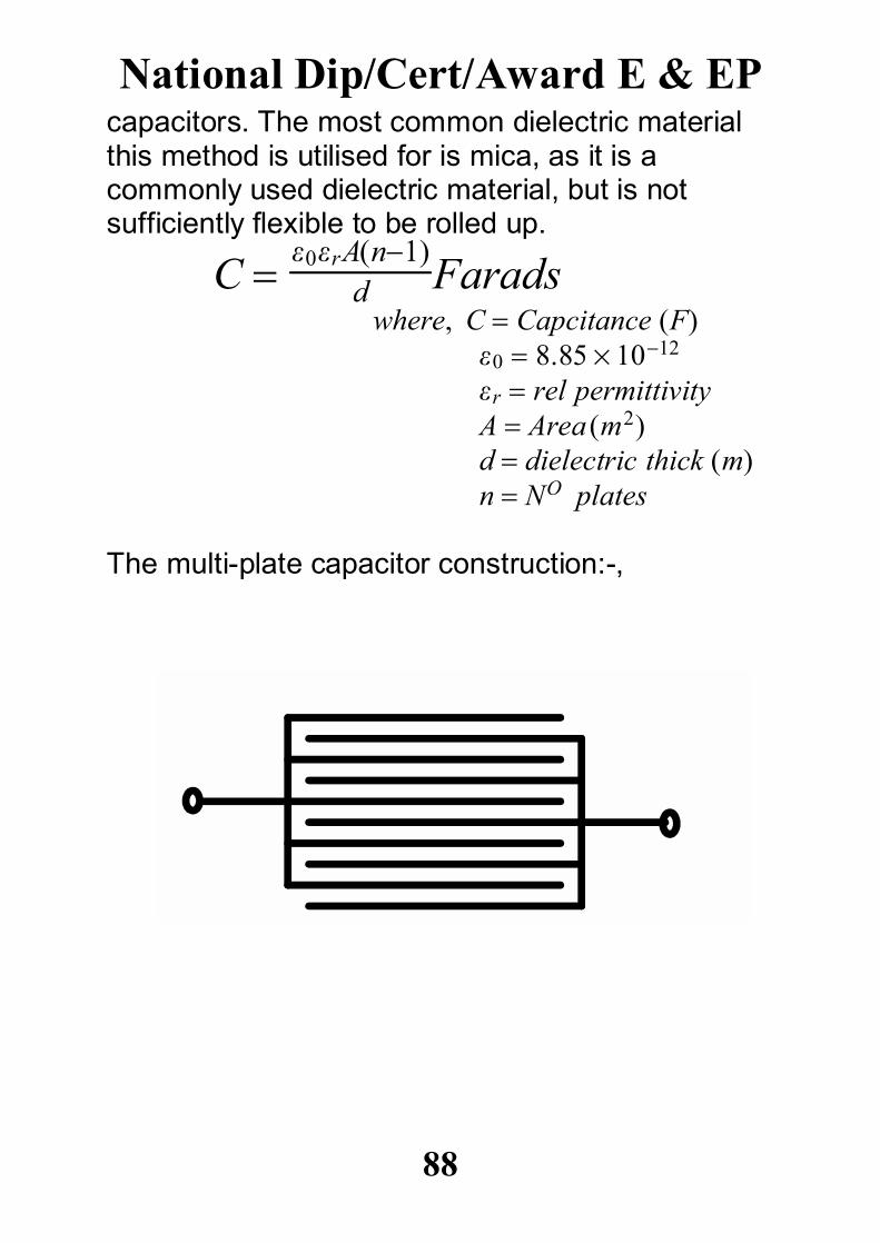
capacitors. The most common dielectric materialthis method is utilised for is mica, as it is acommonly used dielectric material, but is notsufficiently flexible to be rolled up.
C 0rAn1
d Faradswhere, C Capcitance F
0 8.851012
r rel permittivityA Area m2d dielectric thick mn NO plates
The multi-plate capacitor construction:-,
National Dip/Cert/Award E & EP
88
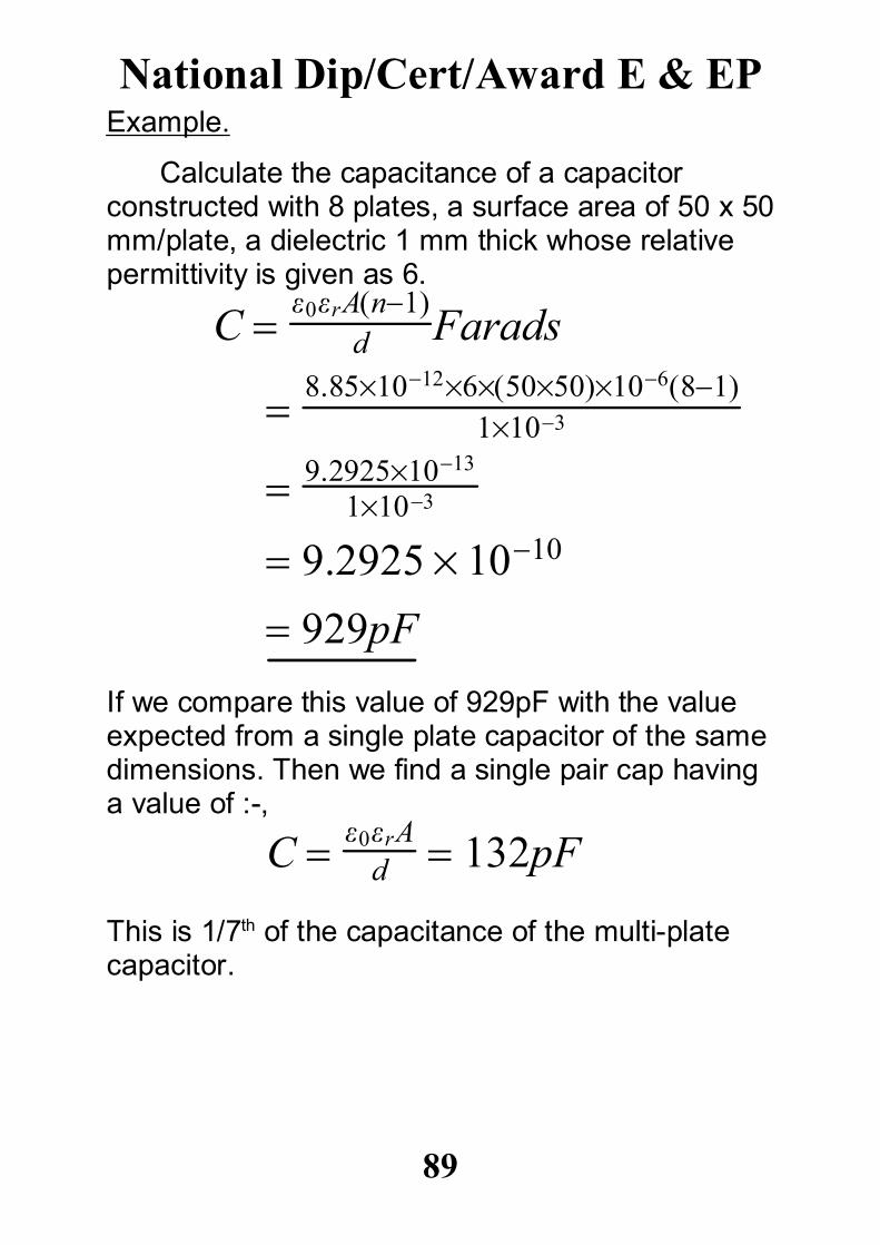
Example.
Calculate the capacitance of a capacitorconstructed with 8 plates, a surface area of 50 x 50mm/plate, a dielectric 1 mm thick whose relativepermittivity is given as 6.
C 0rAn1
d Farads
8.8510126505010681
1103
9.29251013
1103
9.2925 1010
929pF
If we compare this value of 929pF with the valueexpected from a single plate capacitor of the samedimensions. Then we find a single pair cap havinga value of :-,
C 0rAd 132pF
This is 1/7th of the capacitance of the multi-platecapacitor.
National Dip/Cert/Award E & EP
89
Questions 10.1) Calculate the total capacitance of a capacitorwhich is constructed with a surface area of0.005m2, when the dielectric thickness is 0.05mm.If the relative permittivity of the dielectric material is2, and the capacitor is constructed with 20 plates.
2) A capacitor is to be designed to have a totalcapacitance of 10F, the material to be used asthe dielectric requires to be 0.1mm thick to allowthe working voltage of the capacitor to be reached.The relative permittivity of the dielectric material isgiven as 2.5, if the plate dimensions are restrictedto 0.005m2, calculate the number of platesrequired.
National Dip/Cert/Award E & EP
90
Questions 11.1) A direct current of 10A flows into a previouslyuncharged 10F capacitor for 10 ms. Calculate thep.d between the plates.
2) A 20F capacitor is charged at a constantcurrent of 6mA for 1 minute. Calculate the finial p.dacross the capacitor and the corresponding chargein coulombs.
3) Calculate the current required in a circuit tocharge a capacitor with a charge of 0.5 mC, in atime of 200 ms.
National Dip/Cert/Award E & EP
91
4) A parallel plate capacitor is made from 25plates, each 70 mm by 120 mm, interleaved withmica of relative permittivity 5. If the capacitance ofthe capacitor is 5000pF determine the thickness ofthe mica sheet used.
5) The capacitance of a parallel plate capacitor is1000pF. It has 19 plates, each 50 mm by 30 mmseparated by a dielectric of thickness 0.4mm.Determine the relative permittivity of the dielectric.
National Dip/Cert/Award E & EP
92
6) Capacitors of 3F and 5F are connected:a) in parallel.b) in series.
Determine the equilivant capacitance for a & b.
7) Calculate the capacitance to be connected inseries with a 10F capacitor for the equivalentcapacitance to be 6F.
8) When a capacitor is connected across a 240volt supply the charge is 10mC. Find: a) the capacitance.
b) the total energy stored.
National Dip/Cert/Award E & EP
93
9) Show by means of a circuit diagram how acapacitor can be automatically discharged. Why isthis necessary and what sort of values of R wouldbe expected.
You have now reach an AssessmentPoint.
You should now check your work todate.
(covering P4, P5, P6 & M2)
National Dip/Cert/Award E & EP
94