Embed Size (px)
Citation preview
8/17/2019 E-paper Performance 2013 EN1
http://slidepdf.com/reader/full/e-paper-performance-2013-en1 1/28
Performance CUSTOMER MAGAZINE COMPONENTS AND SYSTEMS FOR THE ENGINE AND ITS PERIPHERY 2013
STRONG AND LIGHT:
NEW PISTONSFOR MODERN COMBUSTION ENGINES
8/17/2019 E-paper Performance 2013 EN1
http://slidepdf.com/reader/full/e-paper-performance-2013-en1 2/28
2 MAHLE Performance 2013
CONTENTS
NEWS BRIEFS
MAHLE + Behr = Mehr (More)
ENGINE SYSTEMS AND COMPONENTS
Strong and light: new pistons for modern combustion engines
ENGINE SYSTEMS AND COMPONENTS
Light and cooled: valve technology for optimized thermal management
ENGINE SYSTEMS AND COMPONENTS
Versatile and resistant: oil control r ing for high-performance,
friction-optimized engines
FILTRATION AND ENGINE PERIPHERALS
High-efficiency water separation system: active fuel prefilter module
for diesel engines used around the world
FILTRATION AND ENGINE PERIPHERALS
Higher torque, lower consumption: air intake module with integrated
cascaded charge air cooling
FILTRATION AND ENGINE PERIPHERALS
Replacement for petroleum: bio-based raw materials for air duct components
FILTRATION AND ENGINE PERIPHERALS
Simple construction, significant effect: controlled mechanical
coolant pump for shorter engine warm-up phases
FILTRATION AND ENGINE PERIPHERALS
Synthetic and stable: spin-on oil filter for modern downsizing engines
FILTRATION AND ENGINE PERIPHERALS
With and without activated carbon: new filter media for cabin air filters
MAHLE POWERTRAIN
For more effective component design: new measurement methods
of valve temperatures
IMPRINT
Published by MAHLE International GmbHPragstrasse 26 – 4670376 Stuttgart/Germanywww.mahle.com
Responsible for contents
Arnd Franz
[email protected] +49 711 501-14612Fax +49 711 501- 4414612
Photography/picture creditsMAHLE GmbH, Stuttgart/Germany
Design & productionfreelance project GmbH,Stuttgart/Germany
Reprint, even partially, onlyin accordance with and afterauthorization by the publisher.© MAHLE GmbH, 2013
MAHLE Performance—also as continuously updated version online:
www.performance.mahle.com
4
6
10
12
14
16
18
20
22
24
26
8/17/2019 E-paper Performance 2013 EN1
http://slidepdf.com/reader/full/e-paper-performance-2013-en1 3/28
MAHLE Performance 2013 3
EDITORIAL
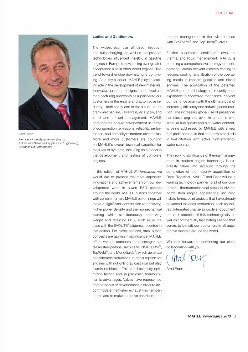
Ladies and Gentlemen,
The widespread use of direct injection
and turbocharging, as well as the product
technologies influenced thereby, in gasoline
engines in Europe is now seeing ever greater
acceptance also in other world regions. The
trend toward engine downsizing is continu-
ing. As a key supplier, MAHLE plays a lead-
ing role in the development of new materials,
innovative product designs, and excellent
manufacturing processes as a partner to our
customers in the engine and automotive in-
dustry—both today and in the future. In the
crank mechanism, valve train, air supply, and
in oil and coolant management, MAHLE
components ensure advancement in termsof consumption, emissions, reliability, perfor-
mance, and durability of modern assemblies.
More and more customers are counting
on MAHLE’s overall technical expertise for
modules or systems, including its support in
the development and testing of complete
engines.
In this edition of MAHLE Performance, we
would like to present the most important
innovations and achievements from our de-
velopment work in seven R&D centers
around the world. MAHLE pistons together
with complementary MAHLE piston rings will
make a significant contribution to achieving
higher power density and thermomechanical
loading while simultaneously optimizing
weight and reducing CO2, such as is the
case with the EVOLITE® pistons presented in
this edition. For diesel engines, steel piston
concepts are gaining in significance. MAHLE
offers various concepts for passenger car
diesel steel pistons, such as MONOTHERM®, TopWeld
®, and MonoGuide
®, which generate
considerable reductions in consumption for
engines with not only gray cast iron but also
aluminum blocks. This is achieved by opti-
mizing friction and, in particular, thermody-
namic advantages. Valves have represented
another focus of development in order to ac-
commodate the higher exhaust gas temper-
atures and to make an active contribution to
Arnd Franz
Member of the Management Board,
Automotive Sales and Application Engineer ing,
Business Unit Aftermarket
thermal management in the cylinder head
with EvoTherm® and TopTherm
® valves.
Further substantial challenges await in
thermal and liquid management. MAHLE is
pursuing a comprehensive strategy of incor-
porating various relevant aspects relating to
feeding, cooling, and filtration of the operat-
ing media in modern gasoline and diesel
engines. The application of the patented
MAHLE pump technology has recently been
expanded to controlled mechanical coolant
pumps, once again with the ultimate goal of
increasing efficiency and reducing consump-
tion. The increasing global use of passenger
car diesel engines, even in countries with
irregular fuel quality and high water content,is being addressed by MAHLE with a new
fuel prefilter module that sets new standards
in fuel filtration with active high-efficiency
water separation.
The growing significance of thermal manage-
ment in modern engine technology is ex-
pressly taken into account through the
completion of the majority acquisition of
Behr. Together, MAHLE and Behr will be a
leading technology partner to all of our cus-
tomers’ thermomechanical tasks in diverse
combustion engine applications, including
hybrid forms. Joint projects that have already
advanced to series production, such as indi-
rect integrated charge air coolers, document
the vast potential of this technologically as
well as commercially fascinating alliance that
serves to benefit our customers in all auto-
motive markets around the world.
We look forward to continuing our close
collaboration with you.
Arnd Franz
8/17/2019 E-paper Performance 2013 EN1
http://slidepdf.com/reader/full/e-paper-performance-2013-en1 4/28
4 MAHLE Performance 2013
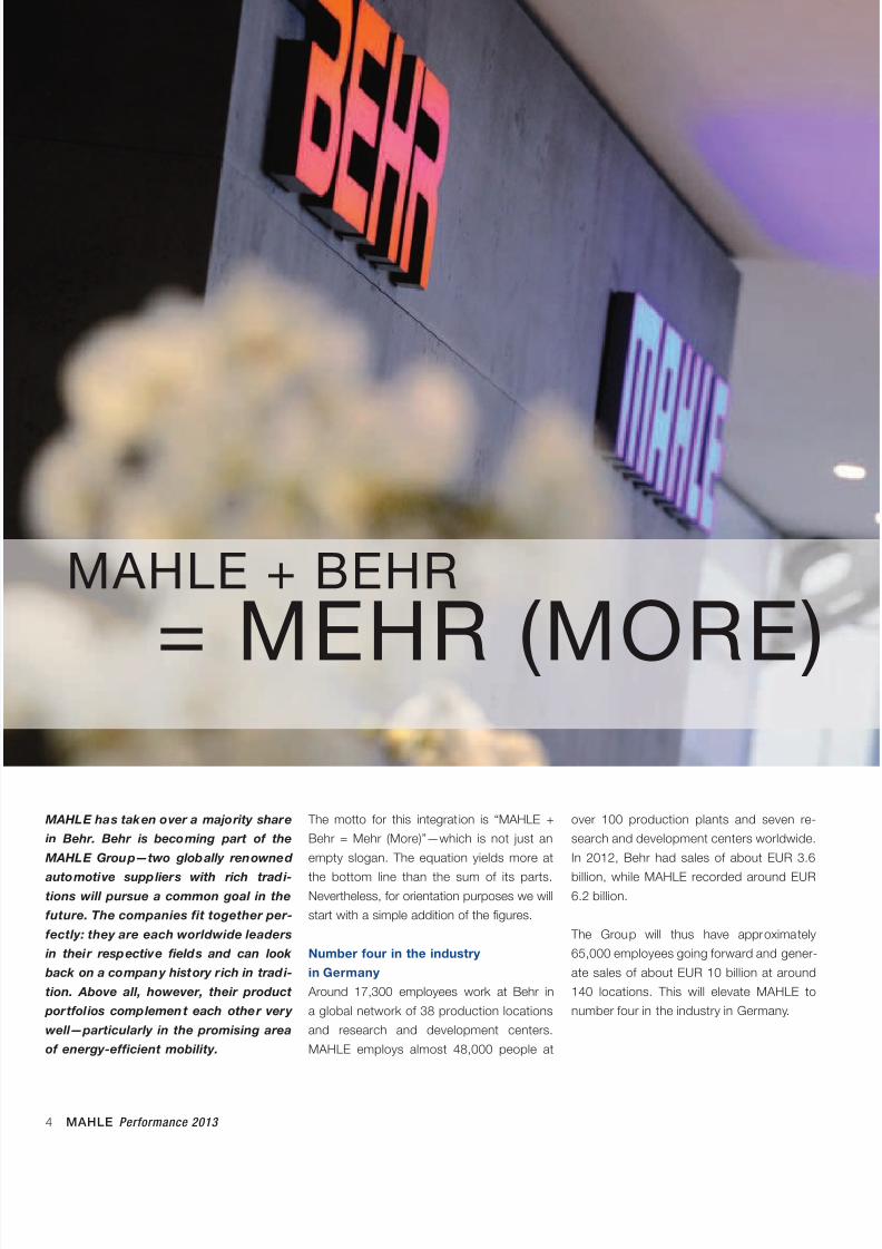
MAHLE has taken over a majority share
in Behr. Behr is becoming part of the
MAHLE Group—two globally renowned
automotive suppliers with rich tradi-
tions will pursue a common goal in the
future. The companies fit together per-
fectly: they are each worldwide leaders
in their respective fields and can look
back on a company history rich in tradi-
tion. Above all, however, their product
portfol ios complement each other very
well—particularly in the promising area
of energy-efficient mobility.
The motto for this integrat ion is “MAHLE +
Behr = Mehr (More)”—which is not just an
empty slogan. The equation yields more at
the bottom line than the sum of its parts.Nevertheless, for orientation purposes we will
start with a simple addition of the figures.
Number four in the industry
in Germany
Around 17,300 employees work at Behr in
a global network of 38 production locations
and research and development centers.
MAHLE employs almost 48,000 people at
over 100 production plants and seven re-
search and development centers worldwide.
In 2012, Behr had sales of about EUR 3.6
billion, while MAHLE recorded around EUR6.2 billion.
The Group will thus have approximately
65,000 employees going forward and gener-
ate sales of about EUR 10 billion at around
140 locations. This will elevate MAHLE to
number four in the industry in Germany.
MAHLE + BEHR
= MEHR (MORE)
8/17/2019 E-paper Performance 2013 EN1
http://slidepdf.com/reader/full/e-paper-performance-2013-en1 5/28
MAHLE Performance 2013 5
NEWS BRIEFS
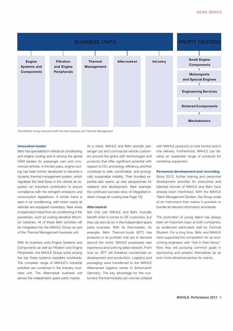
Innovation leader
Behr has specialized in vehicle air conditioning
and engine cooling and is among the global
OEM leaders for passenger cars and com-
mercial vehicles. In the last years, engine cool-
ing has been further developed to become a
dynamic thermal management system, which
regulates the heat flows in the vehicle as re-
quired—an important contribution to ensure
compliance with the stringent emissions and
consumption legislations. A similar trend is
seen in air conditioning, with which nearly all
vehicles are equipped nowadays. New areas
of application result from air conditioning in the
powertrain, such as cooling sensitive lithium-
ion batteries. All of these Behr activities will
be integrated into the MAHLE Group as part
of the Thermal Management business unit.
With its business units Engine Systems and
Components as well as Filtration and Engine
Peripherals, the MAHLE Group ranks among
the top three systems suppliers worldwide.
The complete range of MAHLE’s industrial
activities are combined in the Industry busi-
ness unit. The Aftermarket business unit
serves the independent spare parts market.
BUSINESS UNITS PROFIT CENTERS
Mechatronics
Engine
Systems and
Components
Filtration
and Engine
Peripherals
Thermal
Management
Aftermarket Industry
Engineering Services
Sintered Components
Motorsports
and Special Engines
Small Engine
Components
As a result, MAHLE and Behr provide pas-
senger car and commercial vehicle custom-
ers around the globe with technologies and
products that offer significant potential with
respect to CO2 and energy efficiency, and that
contribute to safe, comfortable, and ecologi-
cally sustainable mobility. Their bundled ex-
pertise also opens up new perspectives for
research and development. Best example:
the continued success story of integrated in-
direct charge air cooling (see Page 16).
Aftermarket
Not only can MAHLE and Behr mutually
benefit when it comes to OE customers, but
they can also do so in the independent spare
parts business. With its thermostats, for
example, Behr Thermot-tronik (BTT) hasproducts in its portfolio that are in demand
around the world. MAHLE possesses vast
experience and a strong sales network. From
now on, BTT will therefore concentrate on
development and production. Logistics and
packaging were transferred to the MAHLE
Aftermarket logistics center in Schorndorf/
Germany. The key advantage for the cus-
tomers: the thermostats can now be collated
with MAHLE products on one invoice and in
one delivery. Furthermore, MAHLE can de-
velop an expanded range of products for
workshop equipment.
Personnel development and recruiting
Since 2012, further training and personnel
development activities for executives and
talented recruits of MAHLE and Behr have
already been interlinked. With the MAHLE
Talent Management System, the Group avails
of an instrument that makes it possible to
bundle all relevant information worldwide.
The promotion of young talent has always
been an important topic at both companies,
as evidenced particularly well by Formula
Student. For a long time, Behr and MAHLEhave supported the competition for up-and-
coming engineers with “fuel in their blood.”
Now they are pursuing common goals in
sponsoring and present themselves as an
even more attractive partner for teams.
The MAHLE Group structure with the new business unit Thermal Management
8/17/2019 E-paper Performance 2013 EN1
http://slidepdf.com/reader/full/e-paper-performance-2013-en1 6/28
6 MAHLE Performance 2013
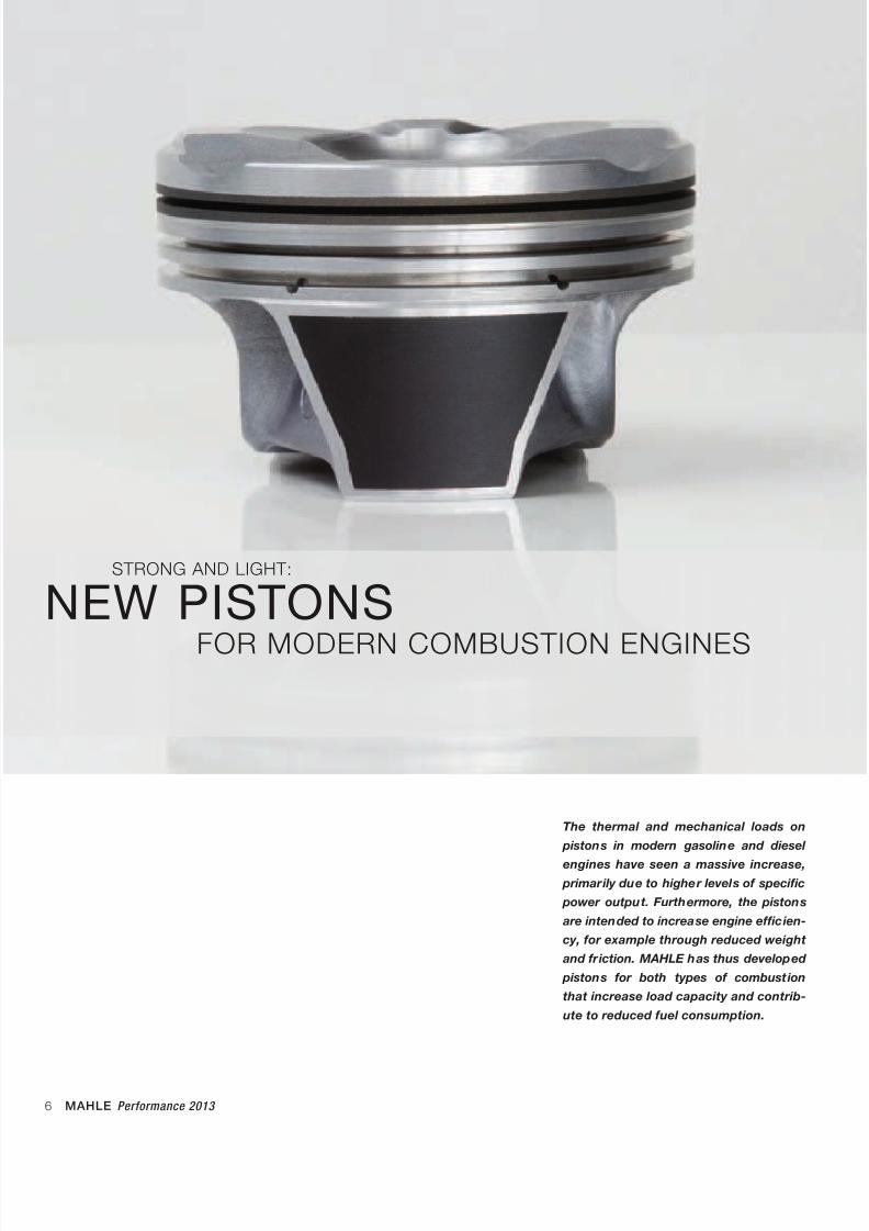
STRONG AND LIGHT:
NEW PISTONSFOR MODERN COMBUSTION ENGINES
The thermal and mechanical loads on
pistons in modern gasoline and diesel
engines have seen a massive increase,
primarily due to higher levels of specific
power output. Furthermore, the pistons
are intended to increase engine efficien-
cy, for example through reduced weight
and friction. MAHLE has thus developed
pistons for both types of combustion
that increase load capacity and contrib-
ute to reduced fuel consumption.
8/17/2019 E-paper Performance 2013 EN1
http://slidepdf.com/reader/full/e-paper-performance-2013-en1 7/28
MAHLE Performance 2013 7
ENGINE SYSTEMS AND COMPONENTS
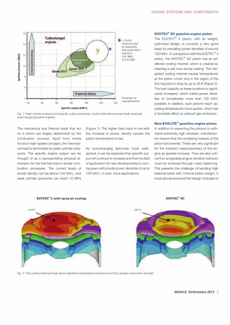
The mechanical and thermal loads that act
on a piston are largely determined by the
combustion process. Apart from inertia
forces in high-speed concepts, the mechani-
cal load is dominated by peak cylinder pres-
sures. The specific engine output can be
thought of as a representative physical di-
mension for the thermal load in similar com-
bustion processes. The current levels of
power density can be above 100 kW/L, and
peak cylinder pressures can reach 12 MPa
(Figure 1). The higher heat input in line with
the increase in power density causes the
piston temperature to rise.
As turbocharging becomes more wide-
spread, it can be expected that specific out-
put will continue to increase and that the field
of application for new developments in com-
ing years will include power densities of up to
130 kW/L, in even more applications.
EVOTEC® SC gasoline engine piston
The EVOTEC® 2 piston, with its weight-
optimized design, is currently a very good
basis for prevailing power densities of around
100 kW/L. In comparison with the EVOTEC® 2
piston, the EVOTEC® SC piston has an ad-
ditional cooling channel, which is created by
inserting a salt core during casting. The inte-
grated cooling channel causes temperatures
at the piston crown and in the region of the
first ring land to drop by up to 25 K (Figure 2).
The load capacity at these locations is signifi-
cantly increased, which makes power densi-
ties of considerably more than 100 kW/L
possible. In addition, such pistons reach op-
erating temperatures more quickly, which has
a favorable effect on exhaust gas emissions.
New EVOLITE® gasoline engine piston
In addition to expecting the pistons to with-
stand extremely high stresses, manufactur-
ers require that the oscillating masses of the
piston be lowered. These are very significant
for the transient responsiveness of the en-
gine as speeds increase. They are also criti-
cal if an acceptable engine vibration behavior
must be achieved through mass balancing.
This presents the challenge of handling high
external loads with minimal piston weight. It
must also be ensured that design changes to
Fig. 1: Peak cylinder pressure and specific output are primary factors that influence part loads (example:turbocharged gasoline engines)
Fig. 2: The cooling channel brings about significant temperature reductions and thus greater component strength
EVOTEC® 2 (with spray jet cooling) EVOTEC
® SC
276 ˚C 251˚C
20 40 60 80 100 120 140
16
14
12
10
8
6
4
Specific output [kW/L]
Passenger car
road applications
= Current
maximum value
for downsizing
high-performance
engines in
A 45 AMG/ CLA 45 AMG
I g n i t i o n p r e s s u r e [ M p
a ]
8/17/2019 E-paper Performance 2013 EN1
http://slidepdf.com/reader/full/e-paper-performance-2013-en1 8/28
8 MAHLE Performance 2013
ENGINE SYSTEMS AND COMPONENTS
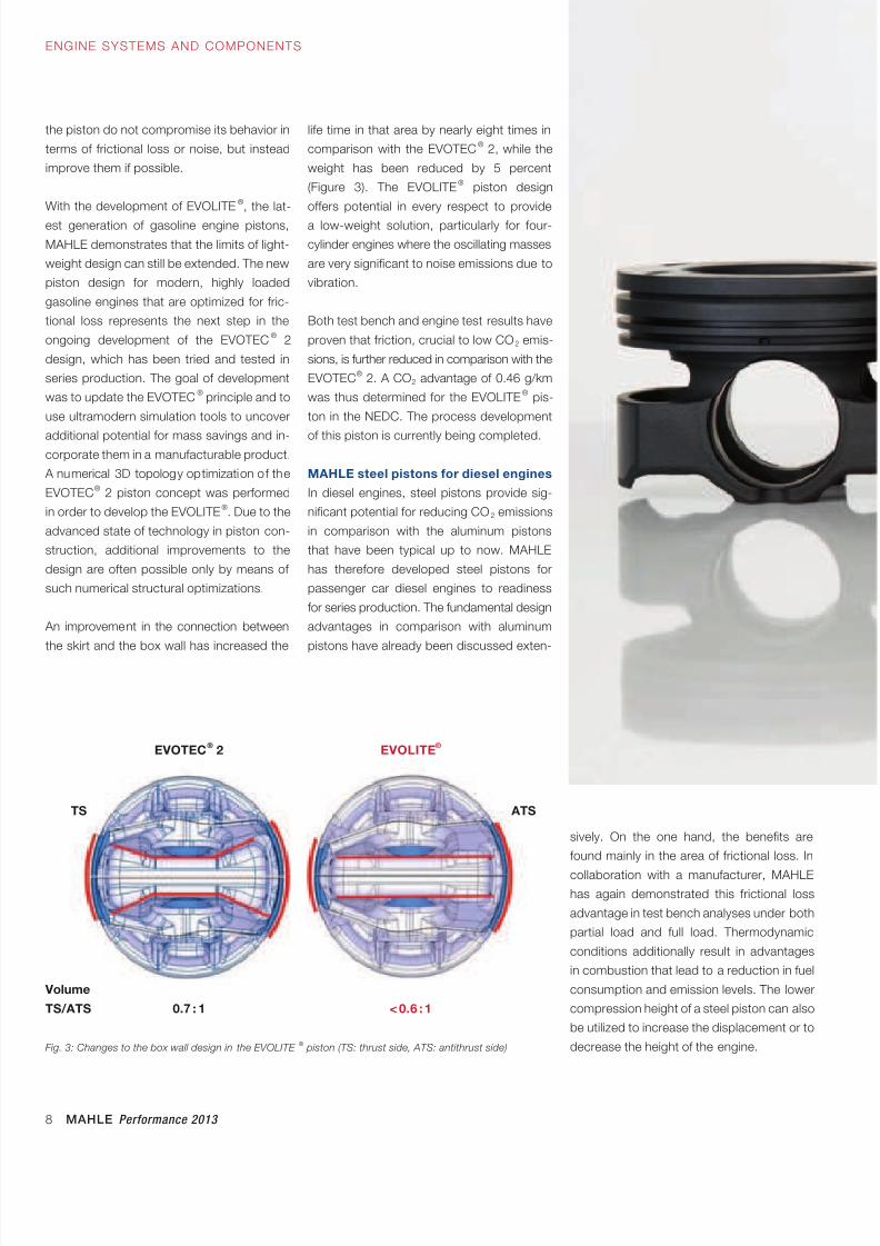
life time in that area by nearly eight times in
comparison with the EVOTEC® 2, while the
weight has been reduced by 5 percent
(Figure 3). The EVOLITE® piston design
offers potential in every respect to provide
a low-weight solution, particularly for four-
cylinder engines where the oscillating masses
are very significant to noise emissions due to
vibration.
Both test bench and engine test results have
proven that friction, crucial to low CO2 emis-
sions, is further reduced in comparison with the
EVOTEC® 2. A CO2 advantage of 0.46 g/km
was thus determined for the EVOLITE® pis-
ton in the NEDC. The process development
of this piston is currently being completed.
MAHLE steel pistons for diesel engines
In diesel engines, steel pistons provide sig-
nificant potential for reducing CO2 emissions
in comparison with the aluminum pistons
that have been typical up to now. MAHLE
has therefore developed steel pistons for
passenger car diesel engines to readiness
for series production. The fundamental design
advantages in comparison with aluminum
pistons have already been discussed exten-
the piston do not compromise its behavior in
terms of frictional loss or noise, but instead
improve them if possible.
With the development of EVOLITE®, the lat-
est generation of gasoline engine pistons,
MAHLE demonstrates that the limits of light-
weight design can still be extended. The new
piston design for modern, highly loaded
gasoline engines that are optimized for fric-
tional loss represents the next step in the
ongoing development of the EVOTEC® 2
design, which has been tried and tested in
series production. The goal of development
was to update the EVOTEC® principle and to
use ultramodern simulation tools to uncover
additional potential for mass savings and in-corporate them in a manufacturable product.
A numerical 3D topology optimization of the
EVOTEC® 2 piston concept was performed
in order to develop the EVOLITE®. Due to the
advanced state of technology in piston con-
struction, additional improvements to the
design are often possible only by means of
such numerical structural optimizations.
An improvement in the connection between
the skirt and the box wall has increased the
sively. On the one hand, the benefits are
found mainly in the area of frictional loss. In
collaboration with a manufacturer, MAHLEhas again demonstrated this frictional loss
advantage in test bench analyses under both
partial load and full load. Thermodynamic
conditions additionally result in advantages
in combustion that lead to a reduction in fuel
consumption and emission levels. The lower
compression height of a steel piston can also
be utilized to increase the displacement or to
decrease the height of the engine.Fig. 3: Changes to the box wall design in the EVOLITE® piston (TS: thrust side, ATS: antithrust side)
EVOLITE®
EVOTEC® 2
TS
Volume
TS/ATS
ATS
< 0.6 : 10.7 : 1
8/17/2019 E-paper Performance 2013 EN1
http://slidepdf.com/reader/full/e-paper-performance-2013-en1 9/28
MAHLE Performance 2013 9
MOTORSYSTEME UND -KOMPONENTEN
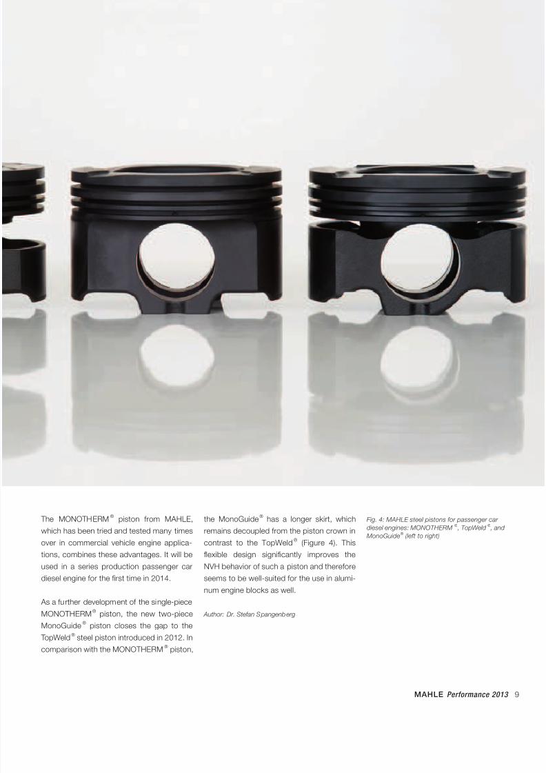
The MONOTHERM® piston from MAHLE,
which has been tried and tested many times
over in commercial vehicle engine applica-tions, combines these advantages. It will be
used in a series production passenger car
diesel engine for the first time in 2014.
As a further development of the single-piece
MONOTHERM® piston, the new two-piece
MonoGuide® piston closes the gap to the
TopWeld® steel piston introduced in 2012. In
comparison with the MONOTHERM® piston,
Fig. 4: MAHLE steel pistons for passenger car
diesel engines: MONOTHERM® , TopWeld
® , and
MonoGuide® (left to right)
the MonoGuide® has a longer skirt, which
remains decoupled from the piston crown in
contrast to the TopWeld® (Figure 4). Thisflexible design significantly improves the
NVH behavior of such a piston and therefore
seems to be well-suited for the use in alumi-
num engine blocks as well.
Author: Dr. Stefan Spangenberg
8/17/2019 E-paper Performance 2013 EN1
http://slidepdf.com/reader/full/e-paper-performance-2013-en1 10/28
10 MAHLE Performance 2013
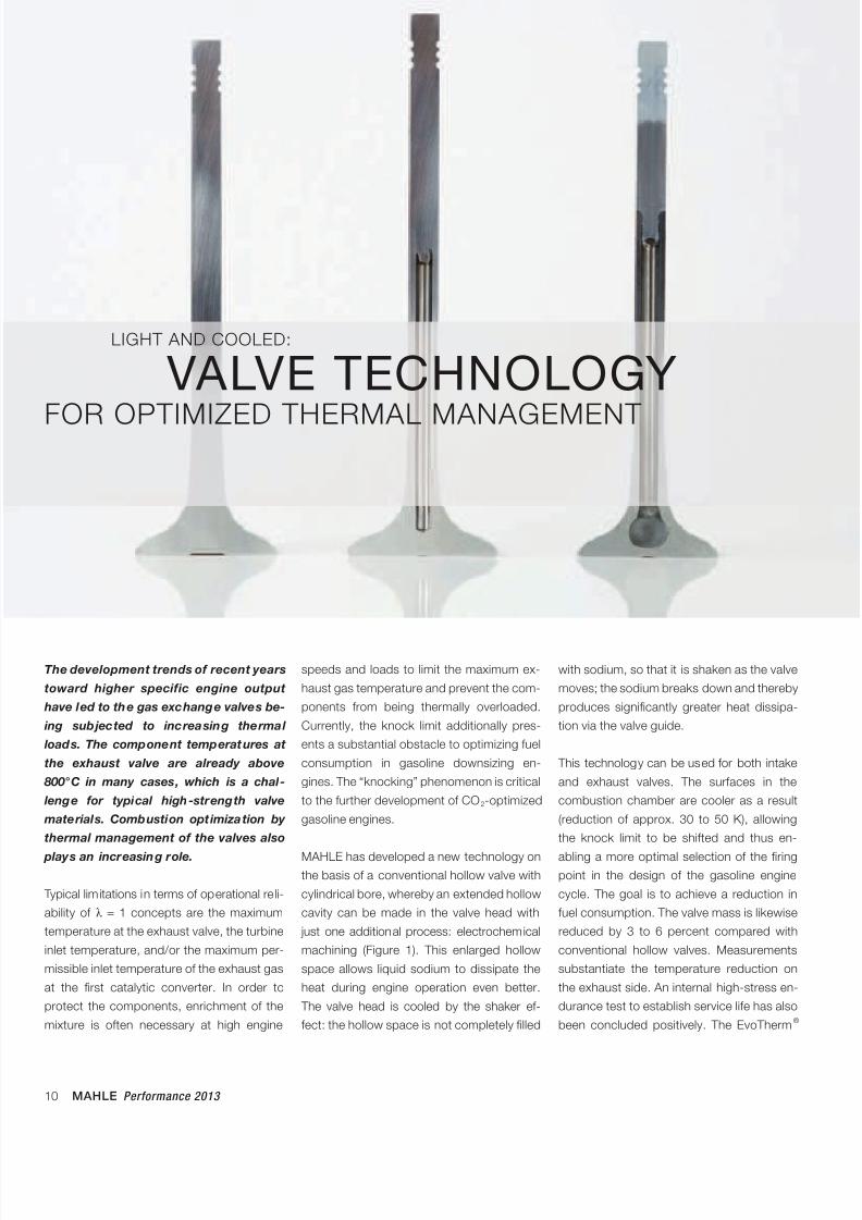
The development trends of recent years
toward higher specific engine output
have led to the gas exchange valves be-
ing subjected to increasing thermal
loads. The component temperatures at
the exhaust valve are already above
800°C in many cases, which is a chal-
lenge for typical high-strength valve
materials. Combustion optimization by
thermal management of the valves also
plays an increasing role.
Typical limitations in terms of operational re li-
ability of λ = 1 concepts are the maximum
temperature at the exhaust valve, the turbine
inlet temperature, and/or the maximum per-
missible inlet temperature of the exhaust gas
at the first catalytic converter. In order to
protect the components, enrichment of the
mixture is often necessary at high engine
speeds and loads to limit the maximum ex-
haust gas temperature and prevent the com-
ponents from being thermally overloaded.
Currently, the knock limit additionally pres-
ents a substantial obstacle to optimizing fuel
consumption in gasoline downsizing en-
gines. The “knocking” phenomenon is critical
to the further development of CO2-optimized
gasoline engines.
MAHLE has developed a new technology onthe basis of a conventional hollow valve with
cylindrical bore, whereby an extended hollow
cavity can be made in the valve head with
just one additional process: electrochemical
machining (Figure 1). This enlarged hollow
space allows liquid sodium to dissipate the
heat during engine operation even better.
The valve head is cooled by the shaker ef-
fect: the hollow space is not completely filled
LIGHT AND COOLED:
VALVE TECHNOLOGY
FOR OPTIMIZED THERMAL MANAGEMENT
with sodium, so that it is shaken as the valve
moves; the sodium breaks down and thereby
produces significantly greater heat dissipa-
tion via the valve guide.
This technology can be used for both intake
and exhaust valves. The surfaces in the
combustion chamber are cooler as a result
(reduction of approx. 30 to 50 K), allowing
the knock limit to be shifted and thus en-
abling a more optimal selection of the firingpoint in the design of the gasoline engine
cycle. The goal is to achieve a reduction in
fuel consumption. The valve mass is likewise
reduced by 3 to 6 percent compared with
conventional hollow valves. Measurements
substantiate the temperature reduction on
the exhaust side. An internal high-stress en-
durance test to establish service life has also
been concluded positively. The EvoTherm®
8/17/2019 E-paper Performance 2013 EN1
http://slidepdf.com/reader/full/e-paper-performance-2013-en1 11/28
MAHLE Performance 2013 11
ENGINE SYSTEMS AND COMPONENTS
valve is an important addition to the MAHLE
product portfolio. The necessity of applying
such technologies is already clearly evident
today.
MAHLE takes a globally leading position in
the area of hollow valves, with decades of
experience. The MAHLE EvoTherm® valve is
the latest development to support engine
manufacturers even more fully as they con-
front current and future challenges in engine
development. Because the EvoTherm® valve
is based on a conventional hollow valve, it
can be considered a low-cost solution.
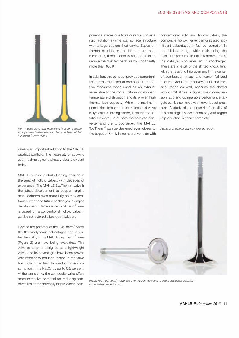
Beyond the potential of the EvoTherm® valve,
the thermodynamic advantages and indus-
trial feasibility of the MAHLE TopTherm® valve(Figure 2) are now being evaluated. This
valve concept is designed as a lightweight
valve, and its advantages have been proven
with respect to reduced friction in the valve
train, which can lead to a reduction in con-
sumption in the NEDC by up to 0.5 percent.
At the same time, the composite valve offers
more extensive potential for reducing tem-
peratures at the thermally highly loaded com-
Fig. 1: Electrochemical machining is used to create
an expanded ho llow space in the valve head of the
EvoTherm® valve (right)
Fig. 2: The TopTherm® valve has a lightweight design and offers additional potential
for temperature reduction
conventional solid and hollow valves, the
composite hollow valve demonstrated sig-
nificant advantages in fuel consumption in
the full-load range while maintaining the
maximum permissible intake temperatures at
the catalytic converter and turbocharger.
These are a result of the shifted knock limit,
with the resulting improvement in the center
of combustion mass and leaner full-load
mixture. Good potential is evident in the tran-
sient range as well, because the shifted
knock limit allows a higher basic compres-
sion ratio and comparable performance tar-
gets can be achieved with lower boost pres-
sure. A study of the industrial feasibility of
this challenging valve technology with regard
to production is nearly complete.
Authors : Chris toph Luven, A lexander Puck
ponent surfaces due to its construction as a
rigid, rotation-symmetrical surface structure
with a large sodium-filled cavity. Based on
thermal simulations and temperature mea-
surements, there seems to be a potential to
reduce the disk temperature by significantly
more than 100 K.
In addition, this concept provides opportuni-
ties for the reduction of component protec-
tion measures when used as an exhaust
valve, due to the more uniform component
temperature distribution and its proven high
thermal load capacity. While the maximum
permissible temperature of the exhaust valve
is typically a limiting factor, besides the in-
take temperature at both the catalytic con-verter and the turbocharger, the MAHLE
TopTherm® can be designed even closer to
the target of λ = 1. In comparative tests with
8/17/2019 E-paper Performance 2013 EN1
http://slidepdf.com/reader/full/e-paper-performance-2013-en1 12/28
12 MAHLE Performance 2013
VERSATILE AND RESISTANT:
OIL CONTROL RINGFOR HIGH-PERFORMANCE, FRICTION-OPTIMIZED ENGINES
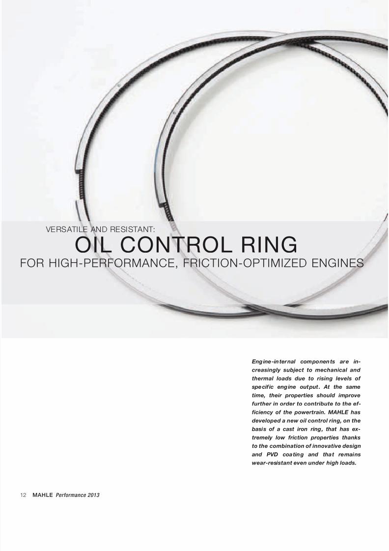
Eng ine-internal components are in-
creasingly subject to mechanical and
thermal loads due to rising levels of
specif ic eng ine output . At the same
time, their properties should improve
further in order to contribute to the ef-
ficiency of the powertrain. MAHLE has
developed a new oil control ring, on the
basis of a cast iron ring, that has ex-
tremely low friction properties thanks
to the combination of innovative design
and PVD coating and that remains
wear-resistant even under high loads.
8/17/2019 E-paper Performance 2013 EN1
http://slidepdf.com/reader/full/e-paper-performance-2013-en1 13/28
MAHLE Performance 2013 13
ENGINE SYSTEMS AND COMPONENTS
trend is toward reducing the cross-sectional
area of the rings. The contact land area must
be adapted at the same time, however, in
order to retain the surface pressure of the
land, which is ultimately responsible for
scraping off the oil. Starting from the origi-
nally common land width of about 0.3 mm,
current development has arrived at a nomi-
nal value of down to 0.1 mm—about the
thickness of a sheet of paper, which pres-
ents considerable challenges with respect to
wear resistance.
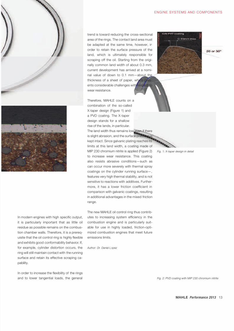
Therefore, MAHLE counts on a
combination of the so-called
X-taper design (Figure 1) and
a PVD coating. The X-taperdesign stands for a shallow
rise of the lands, in particular.
The land width thus remains low even if there
is slight abrasion, and the surface pressure is
kept intact. Since galvanic plating reaches its
limits at this land width, a coating made of
MIP 230 chromium nitrite is applied (Figure 2)
to increase wear resistance. This coating
also resists abrasive conditions—such as
can occur more severely with thermal spray
coatings on the cylinder running surface—,
features very high thermal stability, and is not
sensitive to reactions with additives. Further-
more, it has a lower friction coefficient in
comparison with galvanic coatings, resulting
in additional advantages in the mixed friction
range.
The new MAHLE oil control ring thus contrib-
utes to increasing system efficiency in the
combustion engine and is particularly suit-
able for use in highly loaded, friction-opti-
mized combustion engines that meet futureemissions limits.
Author: Dr. Daniel Lopez
In modern engines with high specific output,
it is particularly important that as little oil
residue as possible remains on the combus-
tion chamber walls. Therefore, it is a prereq-uisite that the oil control ring is highly flexible
and exhibits good conformability behavior. If,
for example, cylinder distortion occurs, the
ring will still maintain contact with the running
surface and retain its effective scraping ca-
pability.
In order to increase the flexibility of the rings
and to lower tangential loads, the general
Fig. 1: X-taper design in detail
Fig. 2: PVD coating with MIP 230 chromium nitrite
8/17/2019 E-paper Performance 2013 EN1
http://slidepdf.com/reader/full/e-paper-performance-2013-en1 14/28
14 MAHLE Performance 2013
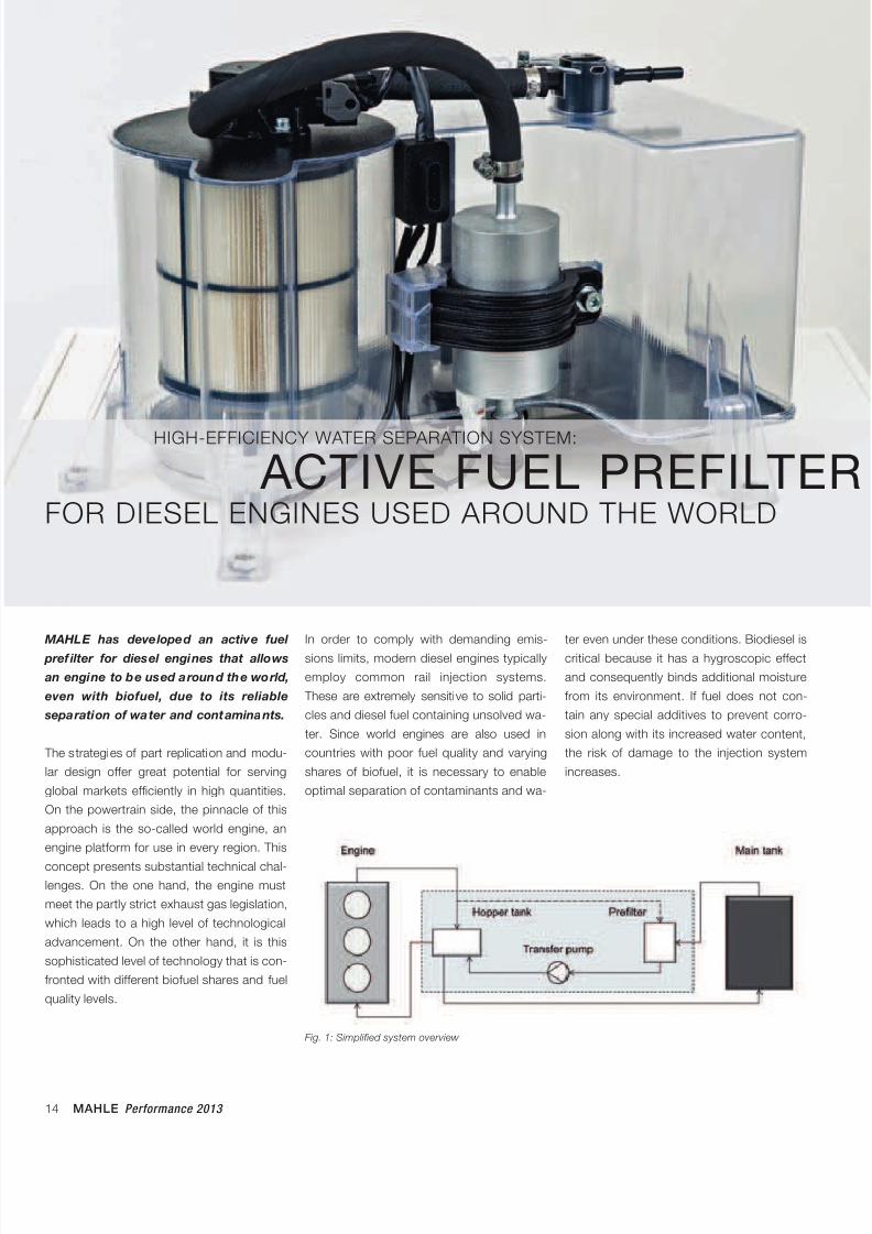
MAHLE has developed an active fuel
pref ilter for diesel engines that allows
an engine to be used around the world,
even with biofuel, due to its reliable
separation of water and contaminants.
The strategies of part replication and modu-
lar design offer great potential for serving
global markets efficiently in high quantities.
On the powertrain side, the pinnacle of this
approach is the so-called world engine, an
engine platform for use in every region. This
concept presents substantial technical chal-lenges. On the one hand, the engine must
meet the partly strict exhaust gas legislation,
which leads to a high level of technological
advancement. On the other hand, it is this
sophisticated level of technology that is con-
fronted with different biofuel shares and fuel
quality levels.
In order to comply with demanding emis-
sions limits, modern diesel engines typically
employ common rail injection systems.
These are extremely sensitive to solid parti-
cles and diesel fuel containing unsolved wa-
ter. Since world engines are also used in
countries with poor fuel quality and varying
shares of biofuel, it is necessary to enable
optimal separation of contaminants and wa-
ter even under these conditions. Biodiesel is
critical because it has a hygroscopic effect
and consequently binds additional moisture
from its environment. If fuel does not con-
tain any special additives to prevent corro-
sion along with its increased water content,
the risk of damage to the injection system
increases.
HIGH-EFFICIENCY WATER SEPARATION SYSTEM:
ACTIVE FUEL PREFILTERFOR DIESEL ENGINES USED AROUND THE WORLD
Fig. 1: Simplified system overview
8/17/2019 E-paper Performance 2013 EN1
http://slidepdf.com/reader/full/e-paper-performance-2013-en1 15/28
MAHLE Performance 2013 15
FILTRATION AND ENGINE PERIPHERALS
MODULE
sient volume flow as a function of the load
state of the engine. The active prefilter is now
located in a separate circuit (Figure 1), which
due to the integration of a so-called hopper
tank that acts as an intermediate tank can be
charged with a largely constant volume flow
rate. This rate is optimized for the filter me-
dium. In addition, this so-called suction-side
arrangement can prevent fine diesel-water
emulsions that are difficult to separate and
are generally caused by the primary pump.
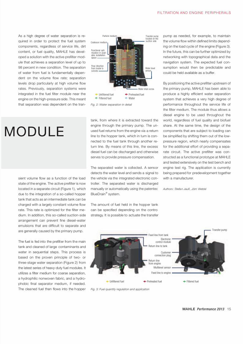
The fuel is fed into the prefilter from the maintank and cleaned of large contaminants and
water in sequential steps. This process is
based on the proven principle of two- or
three-stage water separation (Figure 2) from
the latest series of heavy-duty fuel modules. It
utilizes a filter medium for coarse separation,
a hydrophilic nonwoven fabric, and a hydro-
phobic final separator medium, if needed.
The cleaned fuel then flows into the hopper
tank, from where it is extracted toward theengine through the primary pump. The un-
used fuel returns from the engine via a return
line to the hopper tank, which in turn is con-
nected to the fuel tank through another re-
turn line. By means of this line, the excess
diesel fuel can be discharged and otherwise
serves to provide pressure compensation.
The separated water is collected. A sensor
detects the water level and sends a signal to
the vehicle via the integrated electronic con-
troller. The separated water is discharged
manually or automatically using the patented
BlueDrain® system.
The amount of fuel held in the hopper tank
can be specified depending on the control
strategy. It is possible to actuate the transfer
As a high degree of water separation is re-
quired in order to protect the fuel system
components, regardless of service life, dirt
content, or fuel quality, MAHLE has devel-
oped a solution with the active prefilter mod-
ule that achieves a separation level of up to
98 percent in new condition. The separation
of water from fuel is fundamentally depen-
dent on the volume flow rate; separation
levels drop particularly at high volume flow
rates. Previously, separation systems were
integrated in the fuel filter module near the
engine on the high-pressure side. This meant
that separation was dependent on the tran- Fig. 2: Water separation in detail
pump as needed, for example, to maintain
the volume flow within defined limits depend-
ing on the load cycle of the engine (Figure 3).
In the future, this can be further optimized by
networking with topographical data and the
navigation system. The expected fuel con-
sumption would then be predictable and
could be held available as a buffer.
By positioning the active prefilter upstream of
the primary pump, MAHLE has been able to
produce a highly efficient water separation
system that achieves a very high degree of
performance throughout the service life of
the filter medium. The module thus allows a
diesel engine to be used throughout the
world, regardless of fuel quality and biofuelshare. At the same time, the design of the
components that are subject to loading can
be simplified by shifting them out of the low-
pressure region, which nearly compensates
for the additional effort of providing a sepa-
rate circuit. The active prefilter was con-
structed as a functional prototype at MAHLE
and tested extensively on the test bench and
engine test rig. The application is currently
being prepared for predevelopment together
with a manufacturer.
Authors : Stefan Jauß, Jörn Wetzel
Fig. 3: Fuel quantity regulation and application
Unfiltered fuel Preheated fuel
Filtered fuel Water
Particle medium Transfer pumplocated on thesuction side
Water levelsensor
Water drain screw
Coalescer medium
Functional opti-mization in avail-able installationspace
Flow directionfrom inside tooutside
Feed line from tank
Electroniccontrol module
Return line to tank
Customerconnection plug
Return linefrom engine
Multilevel sensor
Feed line to engine
Transfer pump
Unfiltered fuel Preheated fuel Filtered fuel
8/17/2019 E-paper Performance 2013 EN1
http://slidepdf.com/reader/full/e-paper-performance-2013-en1 16/28
16 MAHLE Performance 2013
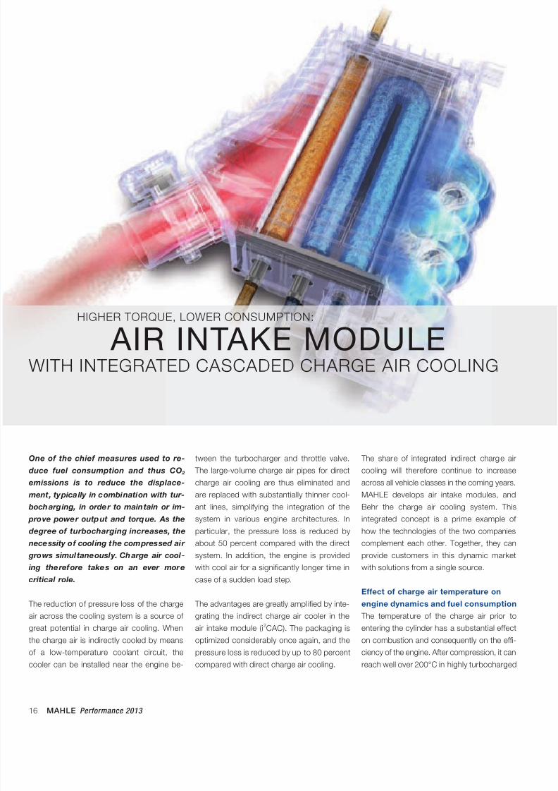
One of the chief measures used to re-
duce fuel consumption and thus CO 2
emissions is to reduce the displace-
ment, typically in combination with tur-
bocharging, in order to maintain or im-
prove power output and torque. As the
degree of turbocharging increases, the
necessity of cooling the compressed air
grows simultaneously. Charge air cool-
ing therefore takes on an ever more
critical role.
The reduction of pressure loss of the charge
air across the cooling system is a source of
great potential in charge air cooling. When
the charge air is indirectly cooled by means
of a low-temperature coolant circuit, the
cooler can be installed near the engine be-
HIGHER TORQUE, LOWER CONSUMPTION:
AIR INTAKE MODULEWITH INTEGRATED CASCADED CHARGE AIR COOLING
tween the turbocharger and throttle valve.
The large-volume charge air pipes for direct
charge air cooling are thus eliminated and
are replaced with substantially thinner cool-
ant lines, simplifying the integration of the
system in various engine architectures. In
particular, the pressure loss is reduced by
about 50 percent compared with the direct
system. In addition, the engine is providedwith cool air for a significantly longer time in
case of a sudden load step.
The advantages are greatly ampl ified by inte-
grating the indirect charge air cooler in the
air intake module (i2CAC). The packaging is
optimized considerably once again, and the
pressure loss is reduced by up to 80 percent
compared with direct charge air cooling.
The share of integrated indirect charge air
cooling will therefore continue to increase
across all vehicle classes in the coming years.
MAHLE develops air intake modules, and
Behr the charge air cooling system. This
integrated concept is a prime example of
how the technologies of the two companies
complement each other. Together, they can
provide customers in this dynamic marketwith solutions from a single source.
Effect of charge air temperature on
engine dynamics and fuel consumption
The temperature of the charge air prior to
entering the cylinder has a substantial effect
on combustion and consequently on the effi-
ciency of the engine. After compression, it can
reach well over 200°C in highly turbocharged
8/17/2019 E-paper Performance 2013 EN1
http://slidepdf.com/reader/full/e-paper-performance-2013-en1 17/28
MAHLE Performance 2013 17
FILTRATION AND ENGINE PERIPHERALS
engines in the full-load range. As a result, the
density of the air flow is lowered, while the
thermal load on the engine components in-
creases. These effects prevent efficient charge
air cooling.
MAHLE has now investigated the impact
on a 1.2-liter three-cylinder gasoline engine.
Cooling the charge air leads to greater mass
volume flow on the intake side. Combustion
is thereby substantially improved, suscepti-
bility to knocking is reduced, and the ignition
point can be advanced. Correspondingly, the
density of the volume flow in the exhaust is
also increased, which makes the turbocharger
more responsive. At low engine speeds, this
results in improved dynamics and increasedtorque. At high engine speeds and loads, the
cooled charge air reduces the need for over-
fueling.
At an ambient temperature of 24°C, an incre-
mental charge air temperature reduction from
60 to 30°C was investigated in the test en-
gine. The most significant improvements were
seen between 45 and 30°C.
The maximum potential for the 1.2-liter three-
cylinder engine was reached under full load
at constant torque, with fuel savings of up to
5 percent, by advancing the ignition point.
The positive effect is further amplified to a
remarkable degree for larger engines with
higher performance.
An alternative approach would be to take
advantage of the lower charge air tempera-
ture in order to increase torque at the same
level of consumption. The result: 7 percent
more torque under full load at low enginespeeds. The low charge air temperature can
thus be utilized in two ways: either for reduc-
ing consumption or for increasing torque.
The lower temperature level of the charge air,
however, cannot be achieved with conven-
tional cooling.
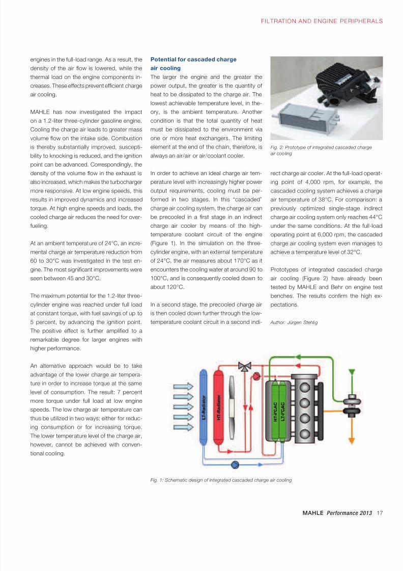
Potential for cascaded charge
air cooling
The larger the engine and the greater the
power output, the greater is the quantity of
heat to be dissipated to the charge air. The
lowest achievable temperature level, in the-
ory, is the ambient temperature. Another
condition is that the total quantity of heat
must be dissipated to the environment via
one or more heat exchangers. The limiting
element at the end of the chain, therefore, is
always an air/air or air/coolant cooler.
In order to achieve an ideal charge air tem-
perature level with increasingly higher power
output requirements, cooling must be per-
formed in two stages. In this “cascaded”charge air cooling system, the charge air can
be precooled in a first stage in an indirect
charge air cooler by means of the high-
temperature coolant circuit of the engine
(Figure 1). In the simulation on the three-
cylinder engine, with an external temperature
of 24°C, the air measures about 170°C as it
encounters the cooling water at around 90 to
100°C, and is consequently cooled down to
about 120°C.
In a second stage, the precooled charge air
is then cooled down further through the low-
temperature coolant circuit in a second indi-
Fig. 1: Schematic design of integrated cascaded charge air cooling
Fig. 2: Prototype of integrated cascaded charge
air coo ling
rect charge air cooler. At the full-load operat-
ing point of 4,000 rpm, for example, the
cascaded cooling system achieves a charge
air temperature of 38°C. For comparison: apreviously optimized single-stage indirect
charge air cooling system only reaches 44°C
under the same conditions. At the full-load
operating point at 6,000 rpm, the cascaded
charge air cooling system even manages to
achieve a temperature level of 32°C.
Prototypes of integrated cascaded charge
air cooling (Figure 2) have already been
tested by MAHLE and Behr on engine test
benches. The results confirm the high ex-
pectations.
Author: Jürgen Stehlig
8/17/2019 E-paper Performance 2013 EN1
http://slidepdf.com/reader/full/e-paper-performance-2013-en1 18/28
18 MAHLE Performance 2013
FILTRATION AND ENGI NE PERIPHERALS
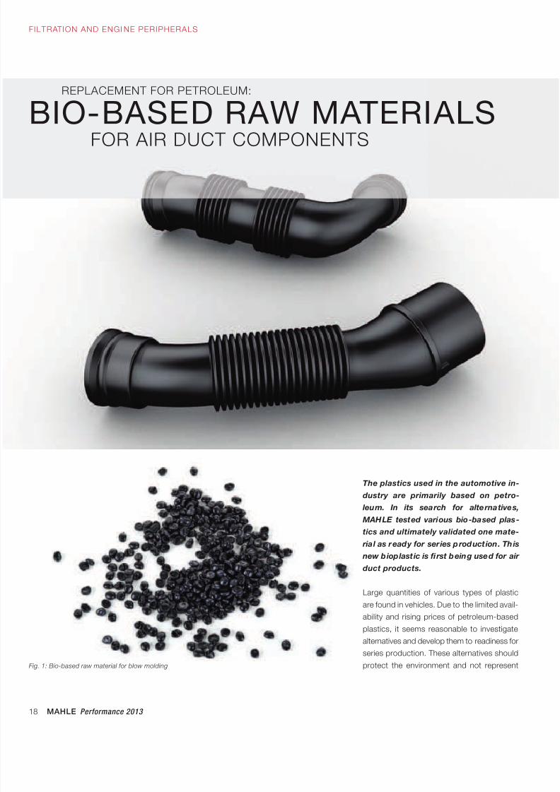
REPLACEMENT FOR PETROLEUM:
FOR AIR DUCT COMPONENTS
BIO-BASED RAW MATERIALS
The plastics used in the automotive in-
dustry are primarily based on petro-
leum. In its search for alternatives,
MAHLE tested various bio-based plas-
tics and ultimately validated one mate-
rial as ready for series production. This
new bioplastic is first being used for air
duct products.
Large quantities of various types of plastic
are found in vehicles. Due to the limited avail-
ability and rising prices of petroleum-based
plastics, it seems reasonable to investigate
alternatives and develop them to readiness for
series production. These alternatives should
protect the environment and not representFig. 1: Bio-based raw material for blow molding
8/17/2019 E-paper Performance 2013 EN1
http://slidepdf.com/reader/full/e-paper-performance-2013-en1 19/28
MAHLE Performance 2013 19
In an effort to validate the properties of the
new bio-based blow mold material, first pro-
totypes were initially produced without modi-
fications to the sample and series production
mold. In comparison with a conventional, pe-
an encroachment on the food chain, i.e., they
should not be based on starch as a raw ma-
terial, for example. Bio-based plastics must
also be available in sufficient quantity.
As part of a predevelopment project, MAHLE,
in conjunction with DuPont Performance
Polymers, has investigated a bio-based blow
mold material (Figure 1) for pipes for unfiltered
air as well as clean air, and advanced it to
series production readiness. Furthermore, a
comparison with conventional petroleum-
based blow mold plastics was performed.
Regardless of the material selection, the re-
quirements for air ducts, such as unfiltered
and clean air lines, continue to rise. The trendtoward a modular system approach demands
more flexible and lightweight components
that can be employed even under very tight
installation space conditions. Another chal-
lenge consists in the low-cost, effective
production of what are often very complex
shapes. The increasingly difficult installation
and removal conditions for service purposes
are central aspects in the development of
current air duct products.
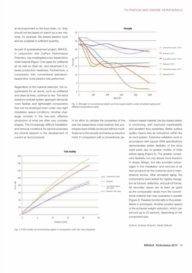
troleum-based material, the bio-based plastic
is convincing, with improved machinability
and excellent flow properties. Better surface
quality means less air turbulence within the
air duct system. Extensive validation work in
accordance with typical OEM specifications
demonstrates better flexibility of the blow
mold parts due to greater motility of folds
before aging (Figure 2). The greater compo-
nent flexibility not only allows more freedom
in shape design, but also provides advan-
tages in the installation and removal of air
duct products for the customer and in main-
tenance service. After simulated aging, the
components were tested for rigidity, elonga-
tion at fracture, deflection, and pull-off forces.
All recorded values are at least as good
as the comparable values from the conven-tional material that was evaluated in parallel
(Figure 3). Flawless functionality is thus estab-
lished in prototypes. Another positive aspect
is the achieved weight reduction, which can
amount up to 25 percent, depending on the
component size.
Authors : Andreas Enderich, Daniel Zielinski
Fig. 3: Strength of conventional plastic and bio-based plastic under simulated aging and
different temperature loads
Fig. 2: Fold motility of conventional plastic in comparison with the new bioplastic
FILTRATION AND ENGINE PERIPHERALS
0 200 400 600 800 1000
Distance [mm]
Conventional plastic
Bioplastic
Conventional plasticafter aging
Bioplastic after aging
Conventional plastic 130°C
Bioplastic 130°C
Conventional plastic 150°C
Bioplastic 150°C
Conventional plastic 160°C
Bioplastic 160°C
Fold motility
Strength
35
30
25
20
15
10
5
0
Agin g [h ]
F o r c e [ N ]
F o r c e [ N ]
0 5 10 15 20 25
160
140
120
100
80
60
40
20
0
8/17/2019 E-paper Performance 2013 EN1
http://slidepdf.com/reader/full/e-paper-performance-2013-en1 20/28
20 MAHLE Performance 2013
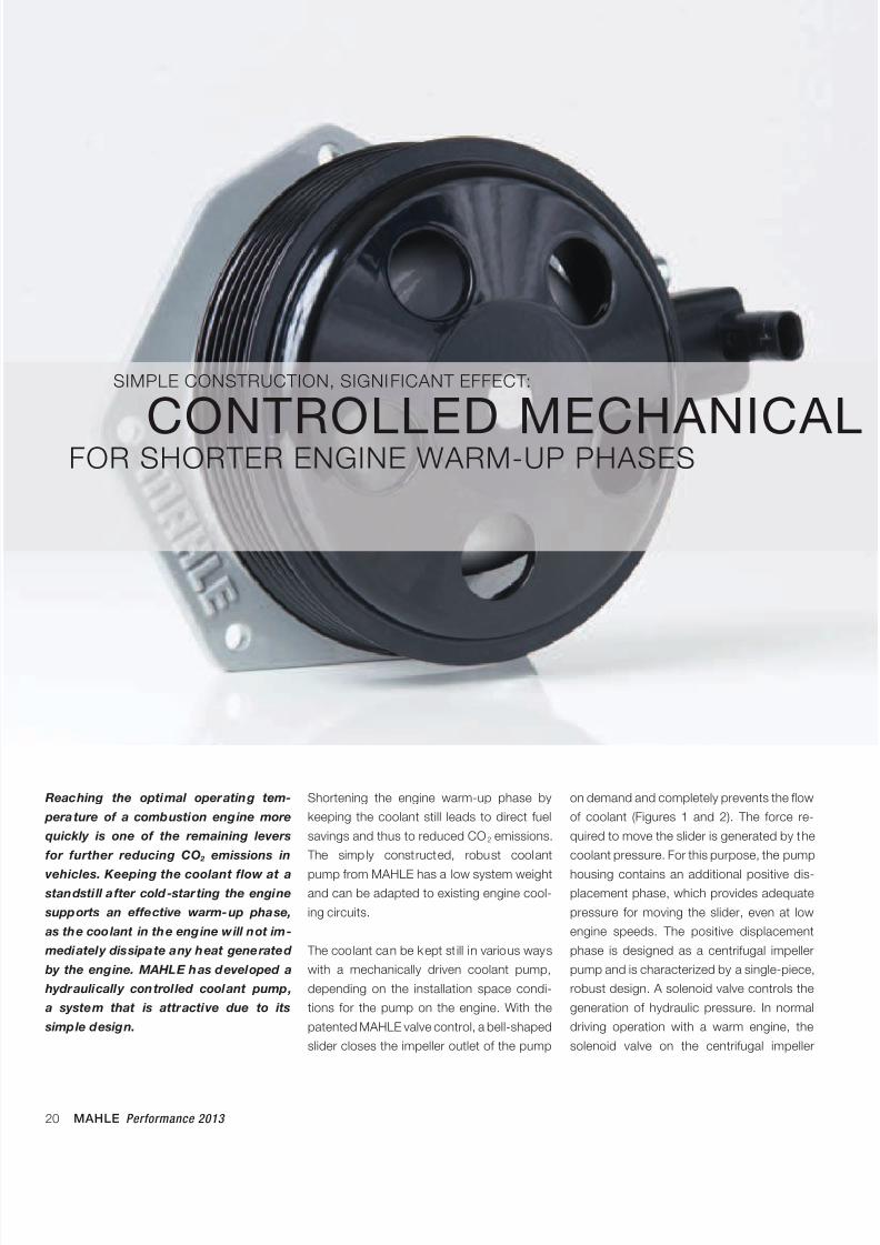
Reaching the optimal operating tem-
perature of a combustion engine more
quickly is one of the remaining levers
for further reducing CO 2 emissions in
vehicles. Keeping the coolant flow at a
standsti ll after cold-starting the engine
supports an effective warm-up phase,
as the coolant in the engine will not im-
mediately dissipate any heat generated
by the engine. MAHLE has developed a
hydraulically controlled coolant pump,
a system that is attractive due to its
simple design.
Shortening the engine warm-up phase by
keeping the coolant still leads to direct fuel
savings and thus to reduced CO2 emissions.
The simply constructed, robust coolant
pump from MAHLE has a low system weightand can be adapted to existing engine cool-
ing circuits.
The coolant can be kept st ill in various ways
with a mechanically driven coolant pump,
depending on the installation space condi-
tions for the pump on the engine. With the
patented MAHLE valve control, a bell-shaped
slider closes the impeller outlet of the pump
SIMPLE CONSTRUCTION, SIGNIFICANT EFFECT:
CONTROLLED MECHANICALFOR SHORTER ENGINE WARM-UP PHASES
on demand and completely prevents the flow
of coolant (Figures 1 and 2). The force re-
quired to move the slider is generated by the
coolant pressure. For this purpose, the pump
housing contains an additional positive dis-placement phase, which provides adequate
pressure for moving the slider, even at low
engine speeds. The positive displacement
phase is designed as a centrifugal impeller
pump and is characterized by a single-piece,
robust design. A solenoid valve controls the
generation of hydraulic pressure. In normal
driving operation with a warm engine, the
solenoid valve on the centrifugal impeller
8/17/2019 E-paper Performance 2013 EN1
http://slidepdf.com/reader/full/e-paper-performance-2013-en1 21/28
MAHLE Performance 2013 21
FILTRATION AND ENGINE PERIPHERALS
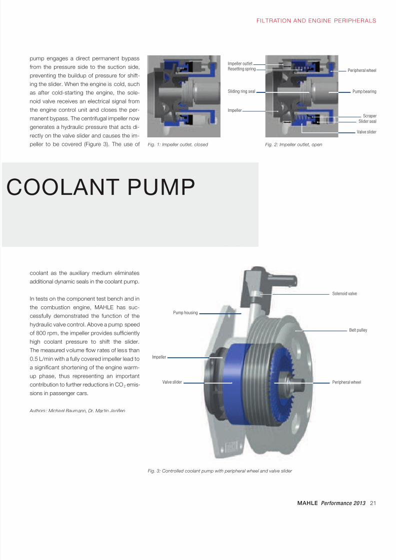
pump engages a direct permanent bypass
from the pressure side to the suction side,
preventing the buildup of pressure for shift-
ing the slider. When the engine is cold, such
as after cold-starting the engine, the sole-
noid valve receives an electrical signal from
the engine control unit and closes the per-
manent bypass. The centrifugal impeller now
generates a hydraulic pressure that acts di-
rectly on the valve slider and causes the im-
peller to be covered (Figure 3). The use of
COOLANT PUMP
Fig. 3: Controlled coolant pump with peripheral wheel and valve slider
Solenoid valve
Pump housing
Impeller
Valve slider
Belt pulley
Peripheral wheel
coolant as the auxiliary medium eliminates
additional dynamic seals in the coolant pump.
In tests on the component test bench and in
the combustion engine, MAHLE has suc-
cessfully demonstrated the function of the
hydraulic valve control. Above a pump speed
of 800 rpm, the impeller provides sufficiently
high coolant pressure to shift the slider.
The measured volume flow rates of less than
0.5 L/min with a fully covered impeller lead to
a significant shortening of the engine warm-
up phase, thus representing an important
contribution to further reductions in CO2 emis-
sions in passenger cars.
Authors : Michael Baumann, Dr. Mar tin Janßen
Fig. 1: Impeller outlet, closed Fig. 2: Impeller outlet, open
Valve slider
Scraper
Pump bearing
Peripheral wheel
Slider seal
Sliding ring seal
Impeller
Impeller outletResetting spring
8/17/2019 E-paper Performance 2013 EN1
http://slidepdf.com/reader/full/e-paper-performance-2013-en1 22/28
22 MAHLE Performance 2013
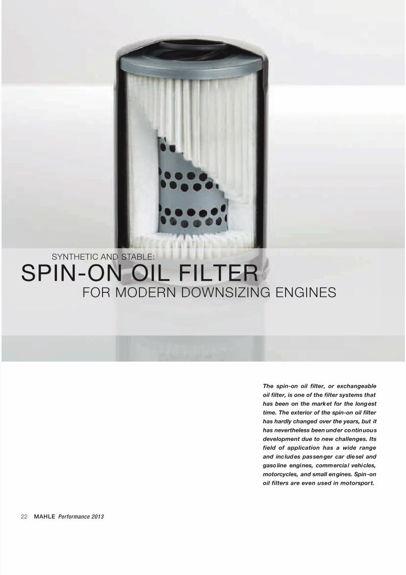
The spin-on oil filter, or exchangeable
oil filter, is one of the filter systems that
has been on the market for the longest
time. The exterior of the spin-on oil filter
has hardly changed over the years, but it
has nevertheless been under continuous
development due to new challenges. Its
field of application has a wide range
and includes passenger car diesel and
gasoline engines, commercial vehicles,
motorcycles, and small engines. Spin-on
oil filters are even used in motor sport.
SYNTHETIC AND STABLE:
SPIN-ON OIL FILTERFOR MODERN DOWNSIZING ENGINES
8/17/2019 E-paper Performance 2013 EN1
http://slidepdf.com/reader/full/e-paper-performance-2013-en1 23/28
MAHLE Performance 2013 23
FILTRATION AND ENGINE PERIPHERALS
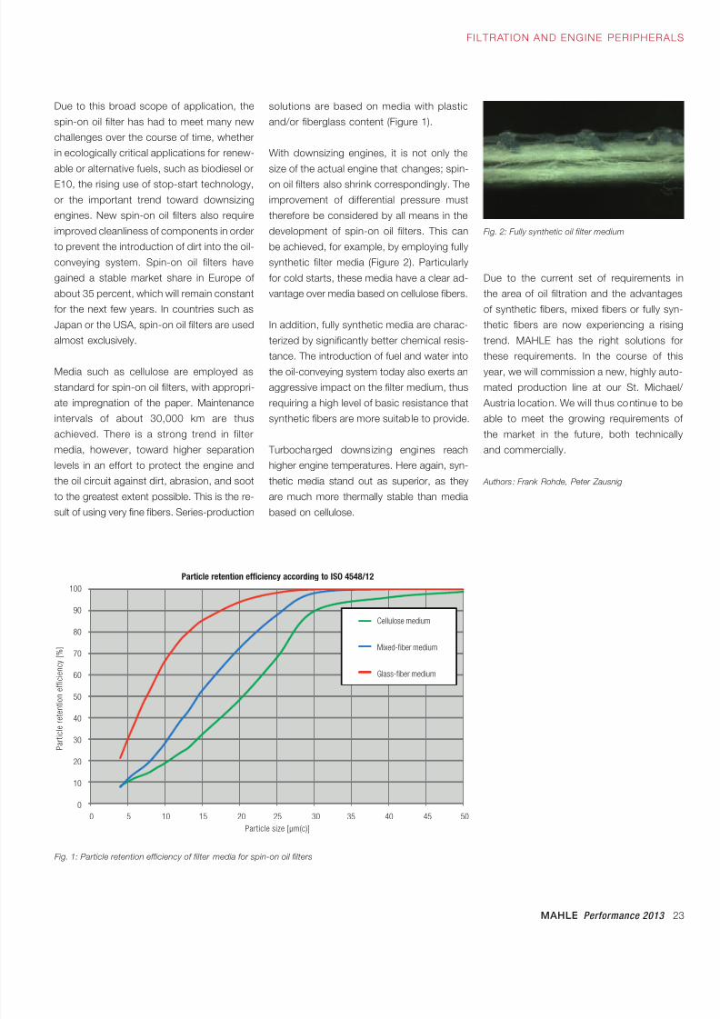
solutions are based on media with plastic
and/or fiberglass content (Figure 1).
With downsizing engines, it is not only the
size of the actual engine that changes; spin-
on oil filters also shrink correspondingly. The
improvement of differential pressure must
therefore be considered by all means in the
development of spin-on oil filters. This can
be achieved, for example, by employing fully
synthetic filter media (Figure 2). Particularly
for cold starts, these media have a clear ad-
vantage over media based on cellulose fibers.
In addition, fully synthetic media are charac-
terized by significantly better chemical resis-
tance. The introduction of fuel and water intothe oil-conveying system today also exerts an
aggressive impact on the filter medium, thus
requiring a high level of basic resistance that
synthetic fibers are more suitab le to provide.
Turbocharged downsizing engines reach
higher engine temperatures. Here again, syn-
thetic media stand out as superior, as they
are much more thermally stable than media
based on cellulose.
Due to this broad scope of application, the
spin-on oil filter has had to meet many new
challenges over the course of time, whether
in ecologically critical applications for renew-
able or alternative fuels, such as biodiesel or
E10, the rising use of stop-start technology,
or the important trend toward downsizing
engines. New spin-on oil filters also require
improved cleanliness of components in order
to prevent the introduction of dirt into the oil-
conveying system. Spin-on oil filters have
gained a stable market share in Europe of
about 35 percent, which will remain constant
for the next few years. In countries such as
Japan or the USA, spin-on oil filters are used
almost exclusively.
Media such as cellulose are employed as
standard for spin-on oil filters, with appropri-
ate impregnation of the paper. Maintenance
intervals of about 30,000 km are thus
achieved. There is a strong trend in filter
media, however, toward higher separation
levels in an effort to protect the engine and
the oil circuit against dirt, abrasion, and soot
to the greatest extent possible. This is the re-
sult of using very fine fibers. Series-production
Fig. 2: Fully synthetic oil filter medium
Fig. 1: Particle retention efficiency of filter media for spin-on oil filters
Cellulosemedium
Mischfasermedium
Glasfasermedium
Due to the current set of requirements in
the area of oil filtration and the advantages
of synthetic fibers, mixed fibers or fully syn-
thetic fibers are now experiencing a rising
trend. MAHLE has the right solutions for
these requirements. In the course of thisyear, we will commission a new, highly auto-
mated production line at our St. Michael/
Austr ia location. We wi ll thus continue to be
able to meet the growing requirements of
the market in the future, both technically
and commercially.
Authors : Frank Rohde, Peter Zausnig
100
90
80
70
60
50
40
30
20
10
0
0 5 10 15 20 25 30 35 40 45 50
Cellulose medium
Mixed-fiber medium
Glass-fiber medium
P a r t i c l e r e t e n t i o n e f f i c i e n c y [ % ]
Particle size [µm(c)]
Particle retention efficiency according to ISO 4548/12
8/17/2019 E-paper Performance 2013 EN1
http://slidepdf.com/reader/full/e-paper-performance-2013-en1 24/28
24 MAHLE Performance 2013
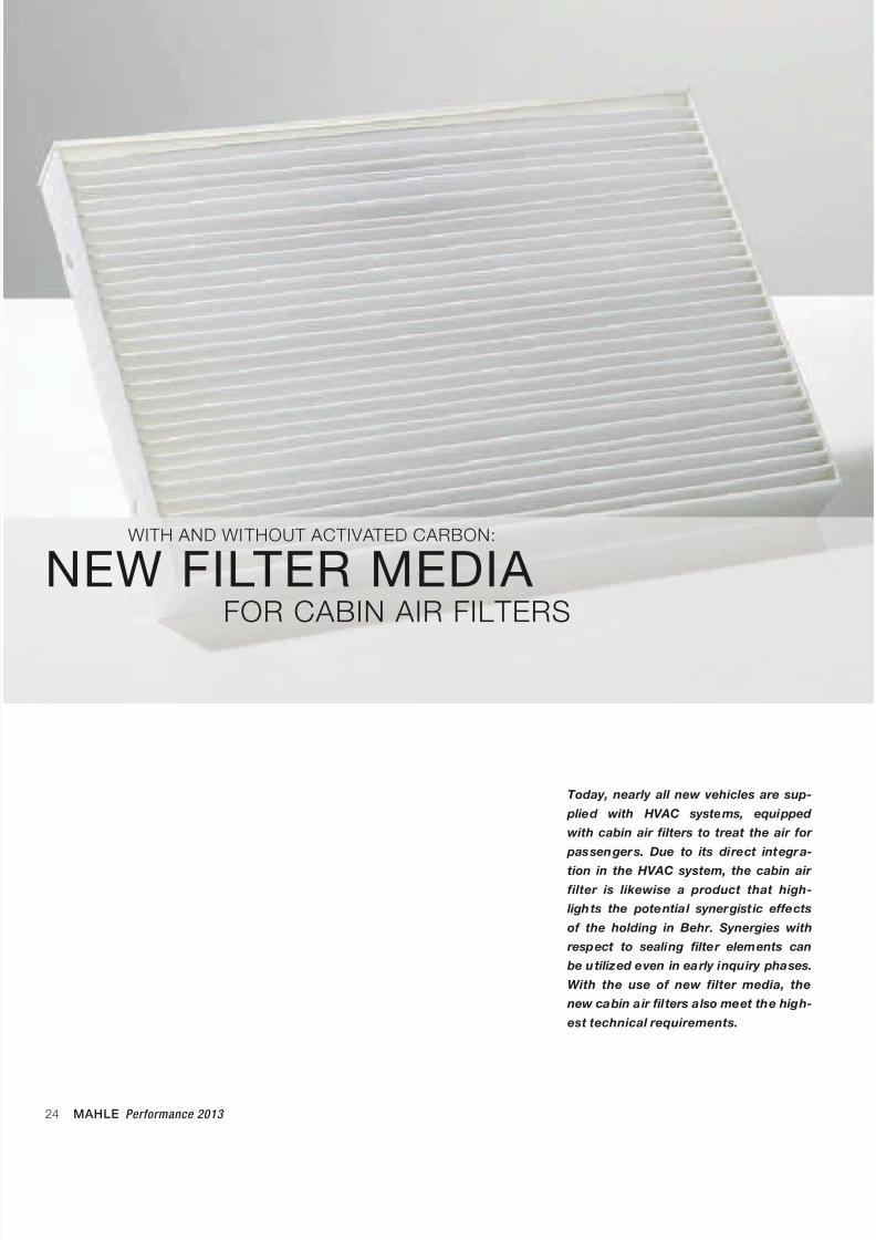
Today, nearly all new vehicles are sup-
plied with HVAC systems, equipped
with cabin air filters to treat the air for
passengers. Due to its direct integra-
tion in the HVAC system, the cabin air
filter is likewise a product that high-
lights the potential synergistic effects
of the holding in Behr. Synergies with
respect to sealing filter elements can
be utilized even in early inquiry phases.
With the use of new filter media, the
new cabin air filters also meet the high-
est technical requirements.
WITH AND WITHOUT ACTIVATED CARBON:
NEW FILTER MEDIA FOR CABIN AIR FILTERS
8/17/2019 E-paper Performance 2013 EN1
http://slidepdf.com/reader/full/e-paper-performance-2013-en1 25/28
MAHLE Performance 2013 25
FILTRATION AND ENGINE PERIPHERALS
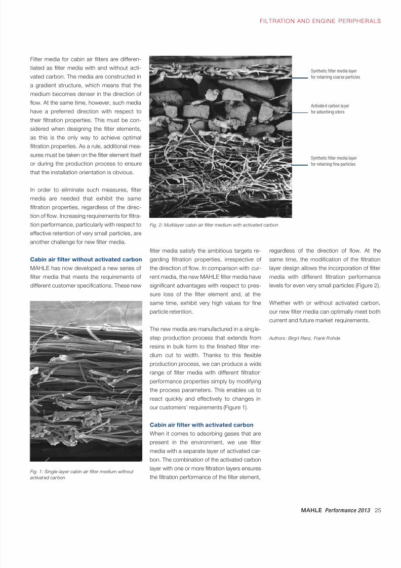
Filter media for cabin air filters are differen-
tiated as filter media with and without acti-
vated carbon. The media are constructed in
a gradient structure, which means that the
medium becomes denser in the direction of
flow. At the same time, however, such media
have a preferred direction with respect to
their filtration properties. This must be con-
sidered when designing the filter elements,
as this is the only way to achieve optimal
filtration properties. As a rule, additional mea-
sures must be taken on the filter element itself
or during the production process to ensure
that the installation orientation is obvious.
In order to eliminate such measures, filter
media are needed that exhibit the samefiltration properties, regardless of the direc-
tion of flow. Increasing requirements for filtra-
tion performance, particularly with respect to
effective retention of very small particles, are
another challenge for new filter media.
Cabin air filter without activated carbon
MAHLE has now developed a new series of
filter media that meets the requirements of
different customer specifications. These new
filter media satisfy the ambitious targets re-
garding filtration properties, irrespective of
the direction of flow. In comparison with cur-
rent media, the new MAHLE filter media have
significant advantages with respect to pres-
sure loss of the filter element and, at the
same time, exhibit very high values for fine
particle retention.
The new media are manufactured in a single-
step production process that extends from
resins in bulk form to the finished filter me-
dium cut to width. Thanks to this flexible
production process, we can produce a wide
range of filter media with different filtration
performance properties simply by modifying
the process parameters. This enables us to
react quickly and effectively to changes inour customers’ requirements (Figure 1).
Cabin air filter with activated carbon
When it comes to adsorbing gases that are
present in the environment, we use filter
media with a separate layer of activated car-
bon. The combination of the activated carbon
layer with one or more filtration layers ensures
the filtration performance of the filter element,
regardless of the direction of flow. At the
same time, the modification of the filtration
layer design allows the incorporation of filter
media with different filtration performance
levels for even very small particles (Figure 2).
Whether with or without activated carbon,
our new filter media can optimally meet both
current and future market requirements.
Authors : Birgi t Renz, Frank Rohde
Fig. 1: Single-layer cabin air filter medium without
activated carbon
Fig. 2: Multilayer cabin air filter medium with activated carbon
Synthetic filter media layer
for retaining coarse particles
Activated carbon la yer
for adsorbing odors
Synthetic filter media layer
for retaining fine particles
8/17/2019 E-paper Performance 2013 EN1
http://slidepdf.com/reader/full/e-paper-performance-2013-en1 26/28
26 MAHLE Performance 2013
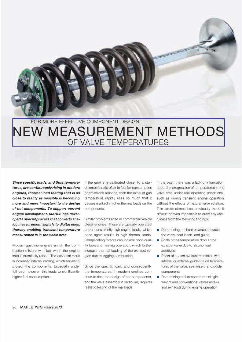
Since specific loads, and thus tempera-
tures, are continuously rising in modern
engines, thermal load testing that is as
close to reality as possible is becoming
more and more important to the design
of hot components. To support current
engine development, MAHLE has devel-
oped a special process that converts ana-
log measurement signals to digital ones,
thereby enabling transient temperature
measurements in the valve area.
Modern gasoline engines enrich the com-
bustion mixture with fuel when the engine
load is drastically raised. The essential result
is increased internal cooling, which serves to
protect the components. Especially under
full load, however, this leads to significantly
higher fuel consumption.
If the engine is calibrated closer to a stoi-
chiometric ratio of air to fuel for consumption
or emissions reasons, then the exhaust gas
temperature rapidly rises so much that it
causes markedly higher thermal loads on the
components.
Similar problems arise in commercial vehicle
diesel engines. These are typically operated
under consistently high engine loads, which
once again results in high thermal loads.
Complicating factors can include poor-qual-ity fuels and heating operation, which further
increase thermal loading of the exhaust re-
gion due to lagging combustion.
Since the specific load, and consequently
the temperatures, in modern engines con-
tinue to rise, the design of hot components,
and the valve assembly in particular, requires
realistic testing of thermal loads.
FOR MORE EFFECTIVE COMPONENT DESIGN:
NEW MEASUREMENT METHODSOF VALVE TEMPERATURES
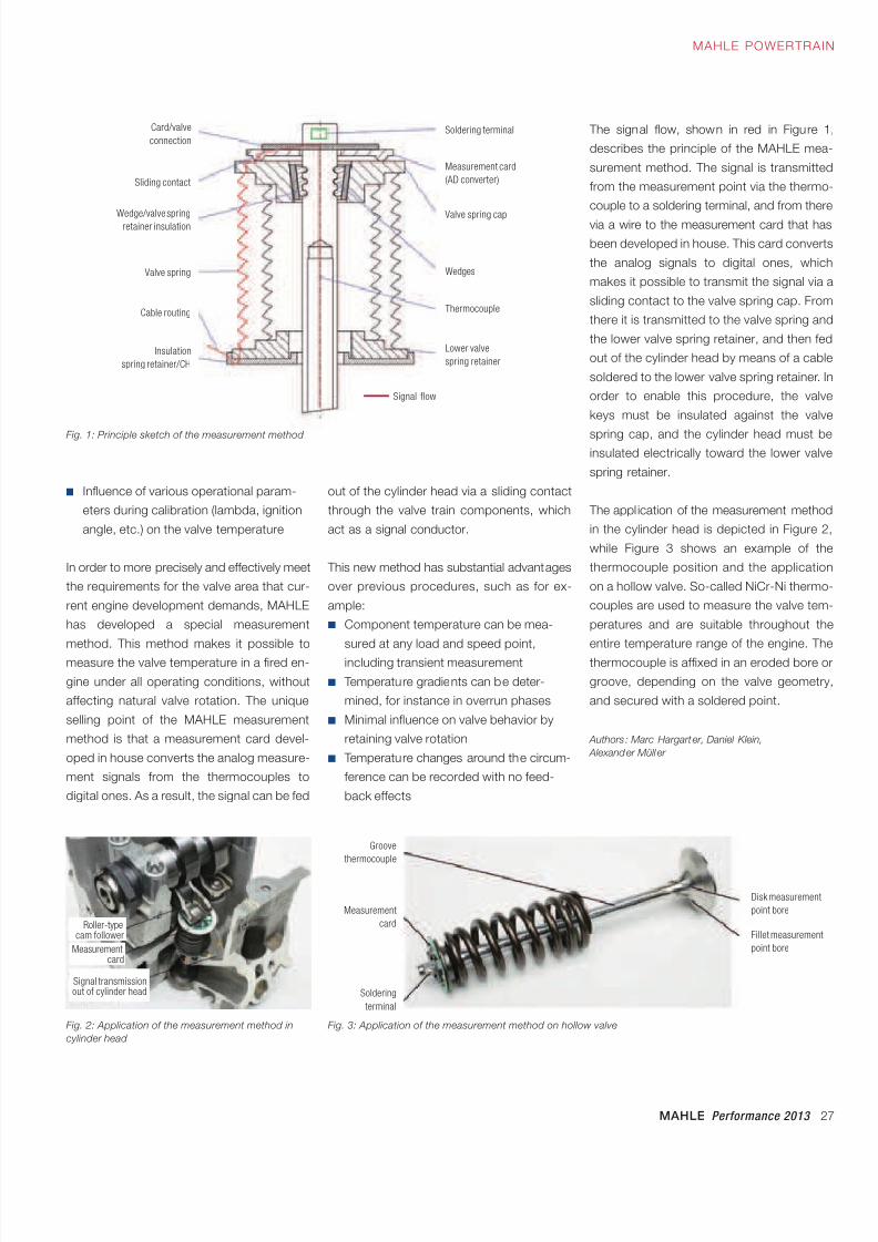
In the past, there was a lack of information
about the progression of temperatures in the
valve area under real operating conditions,
such as during transient engine operation
without the effects of natural valve rotation.
This circumstance has previously made it
difficult or even impossible to draw any use-
fulness from the following findings:
■ Determining the heat balance between
the valve, seat insert, and guide
■ Scale of the temperature drop at theexhaust valve due to alcohol fuel
additives
■ Effect of cooled exhaust manifolds with
internal or external guidance on tempera-
tures of the valve, seat insert, and guide
components
■ Determining real temperatures of light-
weight and conventional valves (intake
and exhaust) during engine operation
8/17/2019 E-paper Performance 2013 EN1
http://slidepdf.com/reader/full/e-paper-performance-2013-en1 27/28
8/17/2019 E-paper Performance 2013 EN1
http://slidepdf.com/reader/full/e-paper-performance-2013-en1 28/28
0 8 / 1 3
w w
w . m a h l e . c o m


![PWX 951HF3 [CDC]GuideForLinux[UNIX]AndWindows En1](https://img.pdfslide.net/doc/110x75/55cf96d0550346d0338df05e/pwx-951hf3-cdcguideforlinuxunixandwindows-en1.jpg)