Embed Size (px)
Citation preview
http://www.bio-protocol.org/e1575 Vol 5, Iss 17, Sep 20, 2015
1
Cryo-focused Ion Beam Sample Preparation for Imaging Vitreous Cells by Cryo-electron
Tomography
Miroslava Schaffer*, Benjamin D. Engel, Tim Laugks, Julia Mahamid, Jürgen M. Plitzko and
Wolfgang Baumeister
Department of Molecular Structural Biology, Max Planck Institute of Biochemistry, Martinsried,
Germany *For correspondence: [email protected]
[Abstract] Cryo-electron tomography (CET) is a well-established technique for imaging
cellular and molecular structures at sub-nanometer resolution. As the method is limited to
samples that are thinner than 500 nm, suitable sample preparation is required to attain CET
data from larger cell volumes. Recently, cryo-focused ion beam (cryo-FIB) milling of
plunge-frozen biological material has been shown to reproducibly yield large, homogeneously
thin, distortion-free vitreous cross-sections for state-of-the-art CET. All eukaryotic and
prokaryotic cells that can be plunge-frozen can be thinned with the cryo-FIB technique.
Together with advances in low-dose microscopy, this has shifted the frontiers of in situ
structural biology. In this protocol we describe the typical steps of the cryo-FIB technique,
starting with fully grown cell cultures. Three recently investigated biological samples are given
as examples.
Materials and Reagents
1. Biological material
Note: The FIB-milling procedure is compatible with a wide range of cell types,
including single-celled eukaryotes, prokaryotes, and mammalian cells such as HeLa
and neuronal cultures. The following examples are used in this protocol:
a. Chlamydomonas reinhardtii (C. reinhardtii) wild-type strain CC-124 (137c)
(Chlamydomonas Resource Center, University of Minnesota, Minneapolis, MN)
b. Chlamydomonas reinhardtii strain mat3-4 (Umen and Goodenough, 2001)
c. Yeast strain Saccharomyces cerevisiae (S. cerevisiae)
2. Tris-acetate-phosphate (TAP) medium (Harris et al., 2009; Culture media recipe is
available at http://www.chlamy.org/media.html)
3. Lugol’s iodine solution (Sigma-Aldrich, catalog number: 62650-100ML-F)
4. Liquid nitrogen
5. Ethane/propane high purity gas mixture (37% ethane) (Linde)
6. Filter paper
7. YPD liquid medium (see Recipes)
http://www.bio-protocol.org/e1575 Vol 5, Iss 17, Sep 20, 2015
2
Equipment
1. R 2/1 Holey Carbon-coated 200-mesh copper grids (Quantifoil Micro Tools GmbH,
catalog number: Q2100CR1)
2. Tweezers
3. Screwdrivers
4. Light microscope
5. Teflon sheets (custom made, cut from larger sheets in the exact shape and size as the
filter paper used for plunge-freezing)
6. Glass petri dish (9-12 cm)
7. Glass microscopy slides (Thermo Fisher Scientific, catalog number: 10144633B)
8. Cryo grid boxes (custom made, or FEI, Eindhoven, The Netherlands)
9. Cryo AutoGrid boxes (custom made, or FEI, Eindhoven, The Netherlands)
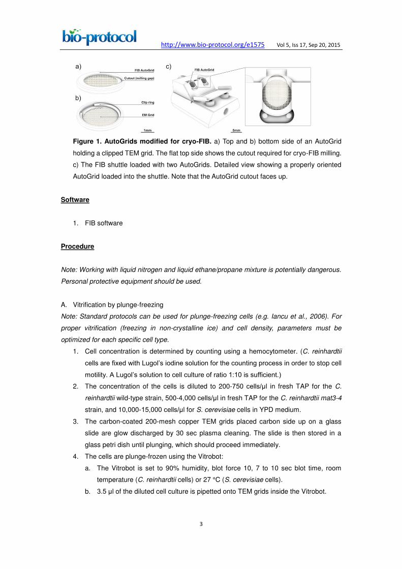
10. AutoGrids (custom made and modified for FIB work, see Figure 1a)
11. Clip rings (FEI, Eindhoven, The Netherlands, see Figure 1b)
12. Liquid nitrogen Dewars
13. Personal protection equipment for work with liquid nitrogen (safety glasses, face shield,
and cold-resistant gloves)
14. Hemocytometer (Neubauer)
15. Pipets and tips
16. Clipping tools (custom made, or FEI, Eindhoven, The Netherlands)
17. Personal protective equipment for work with liquid nitrogen and liquid ethane/propane
18. Plasma cleaner (Harrick, model: PDC-3XG)
19. Vitrobot Mark 4 (FEI)
20. Focused ion beam microscope (FEI, model: DB Quanta 3D FEG), Cryo-system
(Quorum Technologies, model: PP3000T), Cryo-stage (custom made, Max Planck
Institute)
21. Transmission electron microscope I. (FEI, model: Tecnai G2 Polara, FEG 300kV),
Post-column energy-filter (Gatan, model: HR-GIF 2002), Direct detection camera
(Gatan, model: K2 Summit), SerialEM software (Mastronarde, 2005)
22. Transmission electron microscope II. (FEI, model: Titan Krios, FEG 300kV),
post-column energy-filter (Gatan, model: 968 Quantum K2) Direct detection camera
(Gatan, model: K2 Summit), SerialEM software (Mastronarde, 2005)
http://www.bio-protocol.org/e1575 Vol 5, Iss 17, Sep 20, 2015
3
Figure 1. AutoGrids modified for cryo-FIB. a) Top and b) bottom side of an AutoGrid
holding a clipped TEM grid. The flat top side shows the cutout required for cryo-FIB milling.
c) The FIB shuttle loaded with two AutoGrids. Detailed view showing a properly oriented
AutoGrid loaded into the shuttle. Note that the AutoGrid cutout faces up.
Software
1. FIB software
Procedure
Note: Working with liquid nitrogen and liquid ethane/propane mixture is potentially dangerous.
Personal protective equipment should be used.
A. Vitrification by plunge-freezing
Note: Standard protocols can be used for plunge-freezing cells (e.g. Iancu et al., 2006). For
proper vitrification (freezing in non-crystalline ice) and cell density, parameters must be
optimized for each specific cell type.
1. Cell concentration is determined by counting using a hemocytometer. (C. reinhardtii
cells are fixed with Lugol’s iodine solution for the counting process in order to stop cell
motility. A Lugol’s solution to cell culture of ratio 1:10 is sufficient.)
2. The concentration of the cells is diluted to 200-750 cells/μl in fresh TAP for the C.
reinhardtii wild-type strain, 500-4,000 cells/μl in fresh TAP for the C. reinhardtii mat3-4
strain, and 10,000-15,000 cells/μl for S. cerevisiae cells in YPD medium.
3. The carbon-coated 200-mesh copper TEM grids placed carbon side up on a glass
slide are glow discharged by 30 sec plasma cleaning. The slide is then stored in a
glass petri dish until plunging, which should proceed immediately.
4. The cells are plunge-frozen using the Vitrobot:
a. The Vitrobot is set to 90% humidity, blot force 10, 7 to 10 sec blot time, room
temperature (C. reinhardtii cells) or 27 °C (S. cerevisiae cells).
b. 3.5 μl of the diluted cell culture is pipetted onto TEM grids inside the Vitrobot.

http://www.bio-protocol.org/e1575 Vol 5, Iss 17, Sep 20, 2015
4
c. The grids are blotted from the reverse side using Teflon sheets on both sides and
filter paper on the backside. Then they are immediately plunged into the liquid
ethane/propane mixture at liquid nitrogen temperature.
d. The plunge-frozen grids are then stored in sealed boxes under liquid nitrogen until
used.
B. Sample thinning using cryo-FIB milling
1. Cooling the FIB system from room temperature to cryo conditions.
a. Before starting the cooling, the vacuum in the FIB chamber and in the
prep-chamber must be lower than 4 x 10⁻⁶ mbar to avoid contamination from water
vapor.
b. The N2 gas pipeline between the liquid nitrogen Dewar and the FIB chamber
(vacuum isolated line) is pumped to 2 x 10⁻² mbar.
c. The nitrogen gas flow for the stage and anti-contaminator are adjusted to 3.8
L/min and 4.2 L/min, respectively. These values ensure that temperatures of -182
°C and -192 °C are reached after cooling, respectively.
d. The cooling is started by slowly inserting the cooling rod into the liquid nitrogen
Dewar.
2. Sample clipping and loading the AutoGrids into the FIB shuttle.
Note: Clipping and loading is started when the cryo-stage and anti-contaminator reach
temperatures below -160 °C. Using a surgical mask can minimize water vapor
contamination of the work area.
a. The shuttle and the clipping support base are placed into the loading box (Figure
2).
b. The loading box is filled with liquid nitrogen.
c. After boiling has finished, the double wall tank is filled with liquid nitrogen by
slightly tilting the loading box (Figure 2).
d. The sample boxes from the storage Dewar are transferred into the loading box
and opened there. Transfer time should be minimized to avoid contamination of
the sample.
e. All tools that will contact the TEM grids are pre-cooled by liquid nitrogen in the
loading box immediately before use.
http://www.bio-protocol.org/e1575 Vol 5, Iss 17, Sep 20, 2015
5
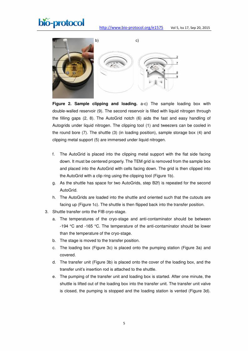
Figure 2. Sample clipping and loading. a-c) The sample loading box with
double-walled reservoir (9). The second reservoir is filled with liquid nitrogen through
the filling gaps (2, 8). The AutoGrid notch (6) aids the fast and easy handling of
Autogrids under liquid nitrogen. The clipping tool (1) and tweezers can be cooled in
the round bore (7). The shuttle (3) (in loading position), sample storage box (4) and
clipping metal support (5) are immersed under liquid nitrogen.
f. The AutoGrid is placed into the clipping metal support with the flat side facing
down. It must be centered properly. The TEM grid is removed from the sample box
and placed into the AutoGrid with cells facing down. The grid is then clipped into
the AutoGrid with a clip ring using the clipping tool (Figure 1b).
g. As the shuttle has space for two AutoGrids, step B2f) is repeated for the second
AutoGrid.
h. The AutoGrids are loaded into the shuttle and oriented such that the cutouts are
facing up (Figure 1c). The shuttle is then flipped back into the transfer position.
3. Shuttle transfer onto the FIB cryo-stage.
a. The temperatures of the cryo-stage and anti-contaminator should be between
-194 °C and -165 °C. The temperature of the anti-contaminator should be lower
than the temperature of the cryo-stage.
b. The stage is moved to the transfer position.
c. The loading box (Figure 3c) is placed onto the pumping station (Figure 3a) and
covered.
d. The transfer unit (Figure 3b) is placed onto the cover of the loading box, and the
transfer unit’s insertion rod is attached to the shuttle.
e. The pumping of the transfer unit and loading box is started. After one minute, the
shuttle is lifted out of the loading box into the transfer unit. The transfer unit valve
is closed, the pumping is stopped and the loading station is vented (Figure 3d).
http://www.bio-protocol.org/e1575 Vol 5, Iss 17, Sep 20, 2015
6
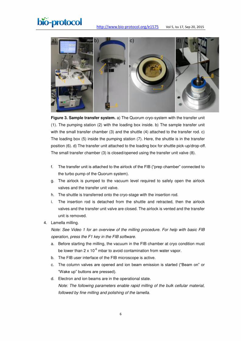
Figure 3. Sample transfer system. a) The Quorum cryo-system with the transfer unit
(1). The pumping station (2) with the loading box inside. b) The sample transfer unit
with the small transfer chamber (3) and the shuttle (4) attached to the transfer rod. c)
The loading box (5) inside the pumping station (7). Here, the shuttle is in the transfer
position (6). d) The transfer unit attached to the loading box for shuttle pick-up/drop-off.
The small transfer chamber (3) is closed/opened using the transfer unit valve (8).
f. The transfer unit is attached to the airlock of the FIB (“prep chamber” connected to
the turbo pump of the Quorum system).
g. The airlock is pumped to the vacuum level required to safely open the airlock
valves and the transfer unit valve.
h. The shuttle is transferred onto the cryo-stage with the insertion rod.
i. The insertion rod is detached from the shuttle and retracted, then the airlock
valves and the transfer unit valve are closed. The airlock is vented and the transfer
unit is removed.
4. Lamella milling.
Note: See Video 1 for an overview of the milling procedure. For help with basic FIB
operation, press the F1 key in the FIB software.
a. Before starting the milling, the vacuum in the FIB chamber at cryo condition must
be lower than 2 x 10⁻⁶ mbar to avoid contamination from water vapor.
b. The FIB user interface of the FIB microscope is active.
c. The column valves are opened and ion beam emission is started (“Beam on” or
“Wake up” buttons are pressed).
d. Electron and ion beams are in the operational state.
Note: The following parameters enable rapid milling of the bulk cellular material,
followed by fine milling and polishing of the lamella.
http://www.bio-protocol.org/e1575 Vol 5, Iss 17, Sep 20, 2015
7
e. The scanning parameters for the electron beam are set to: 5.0 kV beam energy,
12 pA beam current, 1,024 x, 884 or 1,536 x 1,024 scan resolution, 1 µs dwell
time. Scanning is started.
f. Scan rotation for both beams is set to 180 degrees.
g. Low magnification (70x) is set and the stage is moved to one of the two AutoGrids.
h. The grid bar is scanned at increased zoom to adjust focus, astigmatism and other
required alignments for the electron beam.
i. The stage is linked to a focused working distance (“Link Z to FWD” button).
j. The stage is moved to the eucentric height (coincidence point) of the microscope
(ion and electron beams display the same location).
k. The stage rotation is adjusted to align the AutoGrid cutout with the incident
direction of the ion beam. This is achieved by facing the cutout towards the bottom
of the electron image (Figure 4a).
l. Organometallic platinum deposition is performed on both AutoGrids using the in
situ gas injection system to protect the lamella surface and reduce curtaining
effects (protocol adapted from Hayles et al., 2007):
i. Stage parameters are set to 0° tilt and 3 mm below eucentric height.
ii. The stage is adjusted such that the AutoGrid faces the gas injection system
(GIS). For this, a relative stage rotation of 180° is performed using the
compucentric rotation. The AutoGrid is then centered at the GIS position in the
electron image (Figure 4b).
iii. The GIS temperature is set to 26 °C.
iv. The GIS needle is inserted and opened for 4 to 8 sec.
v. The GIS needle is retracted.
vi. The stage is moved back to the initial position where it was before the
procedure.
http://www.bio-protocol.org/e1575 Vol 5, Iss 17, Sep 20, 2015
8
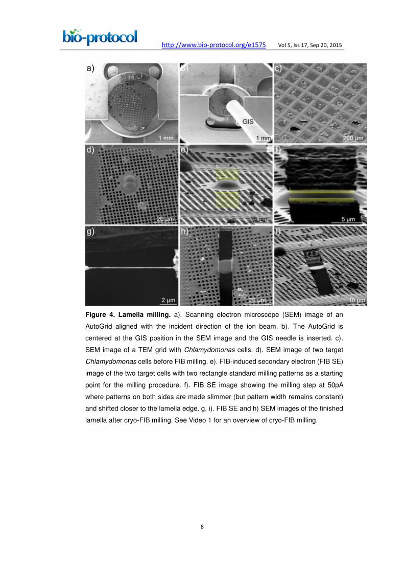
Figure 4. Lamella milling. a). Scanning electron microscope (SEM) image of an
AutoGrid aligned with the incident direction of the ion beam. b). The AutoGrid is
centered at the GIS position in the SEM image and the GIS needle is inserted. c).
SEM image of a TEM grid with Chlamydomonas cells. d). SEM image of two target
Chlamydomonas cells before FIB milling. e). FIB-induced secondary electron (FIB SE)
image of the two target cells with two rectangle standard milling patterns as a starting
point for the milling procedure. f). FIB SE image showing the milling step at 50pA
where patterns on both sides are made slimmer (but pattern width remains constant)
and shifted closer to the lamella edge. g, i). FIB SE and h) SEM images of the finished
lamella after cryo-FIB milling. See Video 1 for an overview of cryo-FIB milling.
http://www.bio-protocol.org/e1575 Vol 5, Iss 17, Sep 20, 2015
9
Video 1. Cryo-FIB milling of a vitreous Chlamydomonas cell
m. The stage is tilted to the milling position with the ion beam almost parallel (typically
6 to 12°) to the grid surface. For a shuttle that is 7° pre-tilted, and a desired milling
angle of 10° with respect to TEM grid surface, the stage is tilted to 17°.
n. The ion beam parameters are set to: 30.0 kV beam energy, 10 pA beam current,
1,024 x 884 or 1,536 x 1,024 scan resolution, 1 µs dwell time.
o. The focus and astigmatism of the ion beam are adjusted while scanning the grid
bar at increased zoom.
p. A target cell is localized in both electron and ion beam images (Figure 4c-e).
Note: The three meshes closest to the edge of the TEM grid are often not
accessible in the TEM microscope. Generally, central meshes are preferred.
q. The eucentric height is adjusted using stage movement in the z-direction so that
the ion beam and the electron beam show the same sample surface.
Note: The eucentric height must be separately adjusted for each milling position.
r. Two parallel rectangular standard milling patterns are drawn (Figure 4e). With
pre-tilt correction disabled, the size of the pattern is approximately 10 x 6 µm and
the distance between the patterns is more than 5 µm. The milling direction is set to
top-to-bottom for one pattern and to bottom-to-top for the other, so that the milling
direction of the pattern is always towards the lamella edge. The milling parameters
are set to: Ice material (or Si), 1 µs dwell time, 60% overlap.
s. The ion beam current is changed to 0.3 nA, and a fast single scan is taken (50 ns
dwell time) to verify the proper milling position.

http://www.bio-protocol.org/e1575 Vol 5, Iss 17, Sep 20, 2015
10
t. The milling process is started. The milling is stopped as soon as the material is
completely removed, as observed by live imaging of the scanned area.
u. Iteratively, the beam current is reduced, pattern heights on both sides are made
slimmer (while keeping pattern widths constant) and patterns are shifted closer to
the lamella edge (Figure 4f and Video 1). Typical steps for the beam current are
0.1 nA, 50 pA and then 30 pA.
v. At a sample thickness of about 500 nm, the final milling is performed using 30 pA
and optionally the cleaning-cross-section pattern. The target lamella thickness is
between 300 and 100 nm (Figure 4g). During this step, thickness is estimated
using electron images (Figure 4h-i).
w. It is possible to prepare multiple lamellas (~10) during one FIB session. For each
new lamella, first set the ion beam current back to 10 pA and then repeat steps
B4p-v).
Note: To minimize time-dependent ice contamination, it is recommended to
perform steps B4p-U at all sample locations first, then afterwards perform
step B4v for each lamella.
5. Shuttle transfer out of the FIB
a. The column valves are closed (“Beam on\off” buttons, or “Sleep” button to end the
FIB session).
b. The stage is moved to the transfer position.
c. The loading box is filled with liquid nitrogen and then placed onto the pumping
station.
d. The transfer unit is docked to the airlock of the FIB.
e. The airlock is pumped to the vacuum level required to safely open the airlock
valves. The airlock valves and the transfer unit valve are then opened.
f. The shuttle is retrieved from the cryo-stage with the insertion rod and retracted out
of the FIB chamber into the transfer unit.
g. The airlock valves and the transfer unit valve are closed.
h. The airlock is vented.
i. The transfer unit is attached to the loading box.
j. The loading station is pumped for 50 sec. Then the transfer unit valve is opened,
and the shuttle is inserted into the loading box with the liquid nitrogen. The
pumping is stopped and the loading station is vented.
k. The insertion rod is detached from the shuttle and the transfer unit is removed.
l. AutoGrids are removed from the shuttle and stored under liquid nitrogen in
storage boxes suitable for AutoGrids.
6. Warming the FIB system
a. The cooling rod is taken out of the liquid nitrogen Dewar.
b. When the cryo-stage and anti-contaminator have reached a temperature of about
20 °C, the gas flow is decreased to 0.5 L/min.
http://www.bio-protocol.org/e1575 Vol 5, Iss 17, Sep 20, 2015
11
C. Cryo-ET
1. The AutoGrid sample is loaded into the cryo-TEM microscope under cryo conditions
using the standard procedure (see FEI user manual). When loading the AutoGrid, the
AutoGrid cutout (and thus the milling direction of the lamellas) must be aligned
perpendicular to the tilt axis of the stage.
2. The lamella positions are localized using low magnification imaging.
3. Tilt-series acquisition is performed using SerialEM software under low-dose conditions
(<100 e/Å2 cumulative dose). K2 images are recorded at 2° tilt increments, with −4 μm
to −8 μm defocus, typically with pixel sizes of 3 to 5 Å.
Representative data
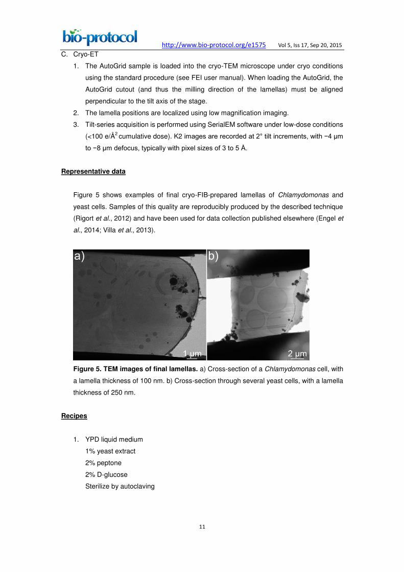
Figure 5 shows examples of final cryo-FIB-prepared lamellas of Chlamydomonas and
yeast cells. Samples of this quality are reproducibly produced by the described technique
(Rigort et al., 2012) and have been used for data collection published elsewhere (Engel et
al., 2014; Villa et al., 2013).
Figure 5. TEM images of final lamellas. a) Cross-section of a Chlamydomonas cell, with
a lamella thickness of 100 nm. b) Cross-section through several yeast cells, with a lamella
thickness of 250 nm.
Recipes
1. YPD liquid medium
1% yeast extract
2% peptone
2% D-glucose
Sterilize by autoclaving
http://www.bio-protocol.org/e1575 Vol 5, Iss 17, Sep 20, 2015
12
Acknowledgments
We thank Alexander Rigort and Felix Bäuerlein for their contributions to developing the
cryo-FIB technique (Rigort et al., 2012), and Elizabeth Villa for fruitful scientific discussions.
This work was supported by the European Commission's 7th Framework Programme
grant agreements ERC-2012-SyG_318987-ToPAG and
HEALTH-F4-2008-201648/PROSPECTS, the Deutsche Forschungsgemeinschaft
Excellence Clusters CIPSM and SFB 1035, the Federal Ministry of Education and
Research (BMBF), an inter-institutional research initiative of the Max Planck Society, a
postdoctoral research fellowship from the Alexander von Humboldt Foundation (to BDE),
and by EMBO and HFSP postdoctoral research fellowships.
References
1. Engel, B. D., Schaffer, M., Kuhn Cuellar, L., Villa, E., Plitzko, J. M. and Baumeister, W.
(2015). Native architecture of the Chlamydomonas chloroplast revealed by in situ
cryo-electron tomography. Elife 4: e04889.
2. Harris, E. H., Stern, D. B. and Witman, G. B. (2009). The chlamydomonas sourcebook.
Academic Press, Elsevier, 2000.
3. Hayles, M. F., Stokes, D. J., Phifer, D. and Findlay, K. C. (2007). A technique for
improved focused ion beam milling of cryo-prepared life science specimens. J Microsc
226(Pt 3): 263-269.
4. Iancu, C. V., Tivol, W. F., Schooler, J. B., Dias, D. P., Henderson, G. P., Murphy, G. E.,
Wright, E. R., Li, Z., Yu, Z., Briegel, A., Gan, L., He, Y. and Jensen, G. J. (2006).
Electron cryotomography sample preparation using the Vitrobot. Nat Protoc 1(6):
2813-2819.
5. Mastronarde, D. N. (2005). Automated electron microscope tomography using robust
prediction of specimen movements. J Struct Biol 152(1): 36-51.
6. Rigort, A., Villa, E., Bauerlein, F. J., Engel, B. D. and Plitzko, J. M. (2012). Integrative
approaches for cellular cryo-electron tomography: correlative imaging and focused ion
beam micromachining. Methods Cell Biol 111: 259-281.
7. Umen, J. G. and Goodenough, U. W. (2001). Control of cell division by a
retinoblastoma protein homolog in Chlamydomonas. Genes Dev 15(13): 1652-1661.
8. Villa, E., Schaffer, M., Plitzko J. M. and Baumeister, W. (2013). Opening windows into
the cell: Focused-ion-beam milling for cryo-electron tomography. Curr Opin Struc Biol
23(5), 771–777.