Embed Size (px)
Citation preview
A
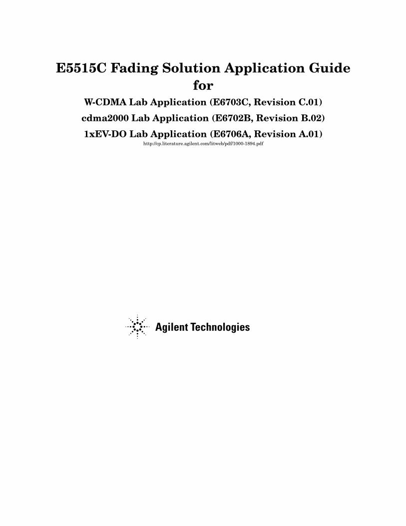
E5515C Fading Solution Application Guidefor
W-CDMA Lab Application (E6703C, Revision C.01)
cdma2000 Lab Application (E6702B, Revision B.02)
1xEV-DO Lab Application (E6706A, Revision A.01)http://cp.literature.agilent.com/litweb/pdf/1000-1894.pdf
2
NoticeInformation contained in this document is subject to change without notice.
All Rights Reserved. Reproduction, adaptation, or translation without prior written permission is prohibited, except as allowed under the copyright laws.
This material may be reproduced by or for the U.S. Government pursuant to the Copyright License under the clause at DFARS 52.227-7013 (APR 1988).
Agilent Technologies, Inc.Learning Products Department24001 E. MissionLiberty Lake, WA 99019-9599U.S.A.
Contents
3
Product Description . . . . . . . . . . . . . . . . . . . . . . . . . . . . . . . . . . . . . . . . . . . . . . . . . . . . . . . . . . . . . 5Hardware and Software Checklist . . . . . . . . . . . . . . . . . . . . . . . . . . . . . . . . . . . . . . . . . . . . . . . . . 7How is a Faded Signal Generated? . . . . . . . . . . . . . . . . . . . . . . . . . . . . . . . . . . . . . . . . . . . . . . . . 8What Fading Patterns are Available? . . . . . . . . . . . . . . . . . . . . . . . . . . . . . . . . . . . . . . . . . . . . . 10
Operating Overview . . . . . . . . . . . . . . . . . . . . . . . . . . . . . . . . . . . . . . . . . . . . . . . . . . . . . . . . . . . . 12Configuring the Fader System . . . . . . . . . . . . . . . . . . . . . . . . . . . . . . . . . . . . . . . . . . . . . . . . . . . 13Using the System Configuration Add Wizard . . . . . . . . . . . . . . . . . . . . . . . . . . . . . . . . . . . . . . . 15Selecting and Testing the System Configuration . . . . . . . . . . . . . . . . . . . . . . . . . . . . . . . . . . . . 21
Faded Test Example Procedures . . . . . . . . . . . . . . . . . . . . . . . . . . . . . . . . . . . . . . . . . . . . . . . . . 24Testing a cdma2000 Mobile Station with a Faded Channel . . . . . . . . . . . . . . . . . . . . . . . . . . . . 25Testing a W-CDMA UE with a Faded Channel . . . . . . . . . . . . . . . . . . . . . . . . . . . . . . . . . . . . . . 38Testing an 1xEV-DO Access Terminal with a Faded Channel . . . . . . . . . . . . . . . . . . . . . . . . . . 50
Fader System Requirements. . . . . . . . . . . . . . . . . . . . . . . . . . . . . . . . . . . . . . . . . . . . . . . . . . . . . 65Critical Fading Solution Settings . . . . . . . . . . . . . . . . . . . . . . . . . . . . . . . . . . . . . . . . . . . . . . . . . 65Power Level Control During Fading . . . . . . . . . . . . . . . . . . . . . . . . . . . . . . . . . . . . . . . . . . . . . . 67Calibration . . . . . . . . . . . . . . . . . . . . . . . . . . . . . . . . . . . . . . . . . . . . . . . . . . . . . . . . . . . . . . . . . . . 70The Digital Bus Connection . . . . . . . . . . . . . . . . . . . . . . . . . . . . . . . . . . . . . . . . . . . . . . . . . . . . . 73Output Power . . . . . . . . . . . . . . . . . . . . . . . . . . . . . . . . . . . . . . . . . . . . . . . . . . . . . . . . . . . . . . . . 75W-CDMA Transmitter Measurement Considerations . . . . . . . . . . . . . . . . . . . . . . . . . . . . . . . . 77Position Location . . . . . . . . . . . . . . . . . . . . . . . . . . . . . . . . . . . . . . . . . . . . . . . . . . . . . . . . . . . . . . 79GPIB Configuration . . . . . . . . . . . . . . . . . . . . . . . . . . . . . . . . . . . . . . . . . . . . . . . . . . . . . . . . . . . 80
Troubleshooting. . . . . . . . . . . . . . . . . . . . . . . . . . . . . . . . . . . . . . . . . . . . . . . . . . . . . . . . . . . . . . . . 81Known Issues . . . . . . . . . . . . . . . . . . . . . . . . . . . . . . . . . . . . . . . . . . . . . . . . . . . . . . . . . . . . . . . . . 81Other Considerations . . . . . . . . . . . . . . . . . . . . . . . . . . . . . . . . . . . . . . . . . . . . . . . . . . . . . . . . . . 82Error Messages . . . . . . . . . . . . . . . . . . . . . . . . . . . . . . . . . . . . . . . . . . . . . . . . . . . . . . . . . . . . . . . 82Checking Fader Hardware Connectivity . . . . . . . . . . . . . . . . . . . . . . . . . . . . . . . . . . . . . . . . . . . 82Related Documentation . . . . . . . . . . . . . . . . . . . . . . . . . . . . . . . . . . . . . . . . . . . . . . . . . . . . . . . . . 83

4
Contents
5
Product Description
Product DescriptionThe Agilent E5515C Fading Solution (referred to as “fader” throughout this document) provides a complete solution for performing faded signal tests on cdma2000, 1xEV-DO and W-CDMA mobile devices by integrating the base station emulation and measurement capability of the 8960 Wireless Communication Test Set (referred to as the “test set” throughout this document) with the digitally generated channel impairments generated by the N5115A Baseband Studio for Fading software (referred to as “fading software” throughout this document).
The primary components of the fader are a test set and a PC with a PCI fader circuit board and fading software.
The test set includes a hardware option that supports a digital interface to the PC for baseband signal data transfer between the devices.
6
Product Description
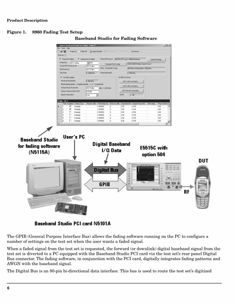
Figure 1. 8960 Fading Test Setup
The GPIB (General Purpose Interface Bus) allows the fading software running on the PC to configure a number of settings on the test set when the user wants a faded signal.
When a faded signal from the test set is requested, the forward (or downlink) digital baseband signal from the test set is diverted to a PC equipped with the Baseband Studio PCI card via the test set’s rear panel Digital Bus connector. The fading software, in conjunction with the PCI card, digitally integrates fading patterns and AWGN with the baseband signal.
The Digital Bus is an 80-pin bi-directional data interface. This bus is used to route the test set’s digitized
Baseband Studio for Fading Software
7
Product Description
baseband I/Q in the outgoing direction to the PC, and then route the incoming faded digital I/Q signal returning from the PC.
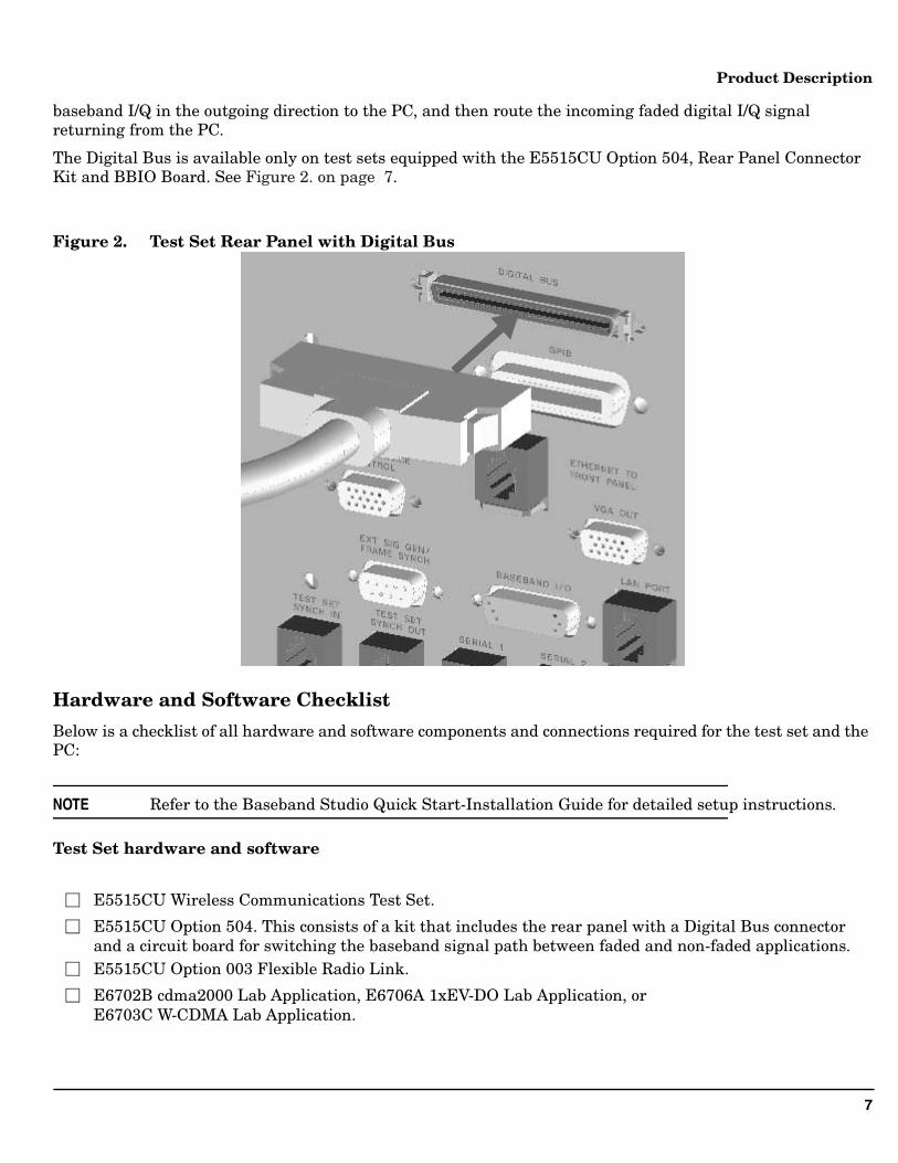
The Digital Bus is available only on test sets equipped with the E5515CU Option 504, Rear Panel Connector Kit and BBIO Board. See Figure 2. on page 7.
Figure 2. Test Set Rear Panel with Digital Bus
Hardware and Software Checklist
Below is a checklist of all hardware and software components and connections required for the test set and the PC:
NOTE Refer to the Baseband Studio Quick Start-Installation Guide for detailed setup instructions.
Test Set hardware and software
E5515CU Option 003 Flexible Radio Link.
E6702B cdma2000 Lab Application, E6706A 1xEV-DO Lab Application, or
E5515CU Wireless Communications Test Set.
E5515CU Option 504. This consists of a kit that includes the rear panel with a Digital Bus connectorand a circuit board for switching the baseband signal path between faded and non-faded applications.
E6703C W-CDMA Lab Application.
8
Product Description
NOTE The E5515CU Option 504 is a field installable upgrade kit. Installation can be performed at the customer’s site.
PC hardware and software
NOTE Minimum PC requirements (processor, memory, etc.) are specified in the N5101A Baseband Studio PCI Card Installation Guide. See “Related Documentation” on page 83.
Cables
How is a Faded Signal Generated?
The Baseband Studio for Fading software running on the PC generates fading patterns and AWGN on the forward channel. RF power levels, including AWGN, are controlled by this software.
The fader software is designed to control the following test set functions via GPIB:
• Selecting the test set’s Open Loop ALC (Automatic Level Control) mode.
N5101A Baseband Studio PCI card.
N5115A Baseband Studio for Fading software.
GPIB interface hardware and software drivers (Agilent 82357A USB/GPIB Interface recommended).
License file (must be saved to C:\Agilent\Program Files\Baseband Studio\LicenseFiles).
N5115A Baseband Studio for Fading Option 160 (one fading channel for up to 17 MHz RFBW).
N5115A Baseband Studio for Fading Option 168 (adds AWGN to a fading channel).
N5115A Baseband Studio for Fading Option 172 (adds E5515C connectivity).
Agilent E2094M IO Libraries Version M.01.02 or later (included with N5515A).
.Net Framework 1.1 (included with N5515A).
Digital Bus cable (included with the N5101A). GP-IB cable (Agilent 82357A USB/GPIB Interface recommended).
RF cable.
9
Product Description
• Configuring the baseband signal path switches to route digital I/Q to and from the Digital Bus.
• Setting up a fading headroom value (see “Impairments Backoff” on page 67).
• Compensation for time delay through the external (Digital Bus) path.
• Setting the test set’s AWGN generator to OFF.
NOTE When the test set is configured to generate a faded signal, the test set’s internal AWGN generator is automatically turned off to allow the AWGN to be added by the external fading software. The resulting RF signal from the test set will have fading applied to the forward or downlink channel only, with no fading applied to AWGN.
Test sets equipped with option 504 have the capability to re-route the digital baseband signal. Using GPIB commands and front panel controls, the test set can be configured to route the baseband IQ digital data to the rear panel Digital Bus interface, where it is converted to a format compatible with the PCI card on the PC (see “The Digital Bus Connection” on page 73).
The Baseband Studio for Fading software running on the PC mathematically integrates fading patterns with the baseband signal depending on the user-requested fading pattern and AWGN setting. The faded digital IQ data is sent back to the test set on the Digital Bus, where it is converted back to the data format used by the test set.
The digitally faded data is then sent to the test set’s analog IQ circuit and provides the forward channel modulation source for the RF output.
The fading software controls the test set’s internal baseband signal path switching when the fader is turned on. See Figure 3. on page 10
10
Product Description
Figure 3. Baseband Signal Transmitter Path
What Fading Patterns are Available?
Fading patterns include:
• Rayleigh
• Flat
• Doppler
• Suzuki
Standard test patterns are available in the software and can be modified if necessary. For example, the cdma2000 mobile test choices include:
• Case 1
• Case 2
• Case 3
• Case 4
• Case 5
8960 Test Set Transmitter Paths
Digital I/Q Analog I/Q
100101001010110
D/A
PC
N5101A PCI Card
Digital Bus Cable
Baseband Switching
11
Product Description
• Case 6
The 1xEV-DO access terminal test choices include:
• Case 1
• Case 2
• Case 3
• Case 4
• Case 5
The W-CDMA mobile test choices include:
• Case 1
• Case 2
• Case 3
• Case 4
• Case 5
• Case 6
• Birth-Death
• Moving Propagation
Descriptions of standard test patterns are provided in the fading software’s online help.

12
Operating Overview
Operating OverviewThis section provides the fundamental operating information for the E5515C Fading Solution (fader).
For reference information about the N5115A Baseband Studio for Fading (fading software) controls, refer to the online help.
For reference information about the E5515C controls, refer to the online reference guides. To access these guides, go to www.agilent.com/find/E6702B (cdma2000 Lab Application), www.agilent.com/find/E6706A (1xEV-DO Lab Application) or www.agilent.com/find/E6703C (W-CDMA Lab Application).
13
Operating Overview
Configuring the Fader System
Before you configure the fader system, the PC must have the N5101A PCI card, software drivers, and fading software license file installed in the PC. See “Hardware and Software Checklist” on page 7.
(For hardware and software installation instructions, refer to the N5101A Baseband Studio PCI Card Installation Guide shipped with the PCI card.)
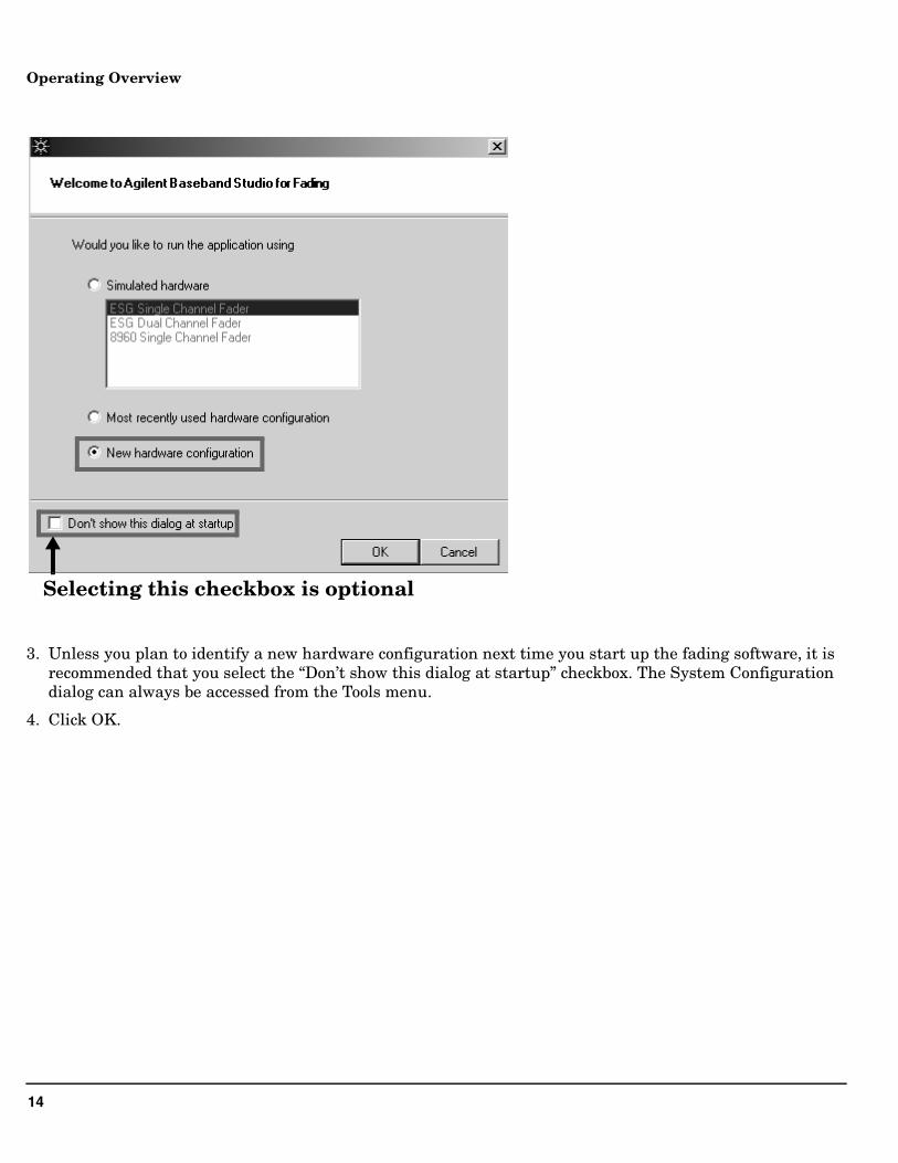
In the fader software Welcome screen there is a System Configuration dialog that is used to setup and test the GPIB and the PCI card interfaces. This dialog gives you access to the System Configuration Add Wizard (wizard), which will setup and verify communication with the fader hardware in your system.
IMPORTANT Make sure the test set’s power is on and a lab application (cdma2000, 1xEV-DO, or W-CDMA) is selected before you configure the fader system.
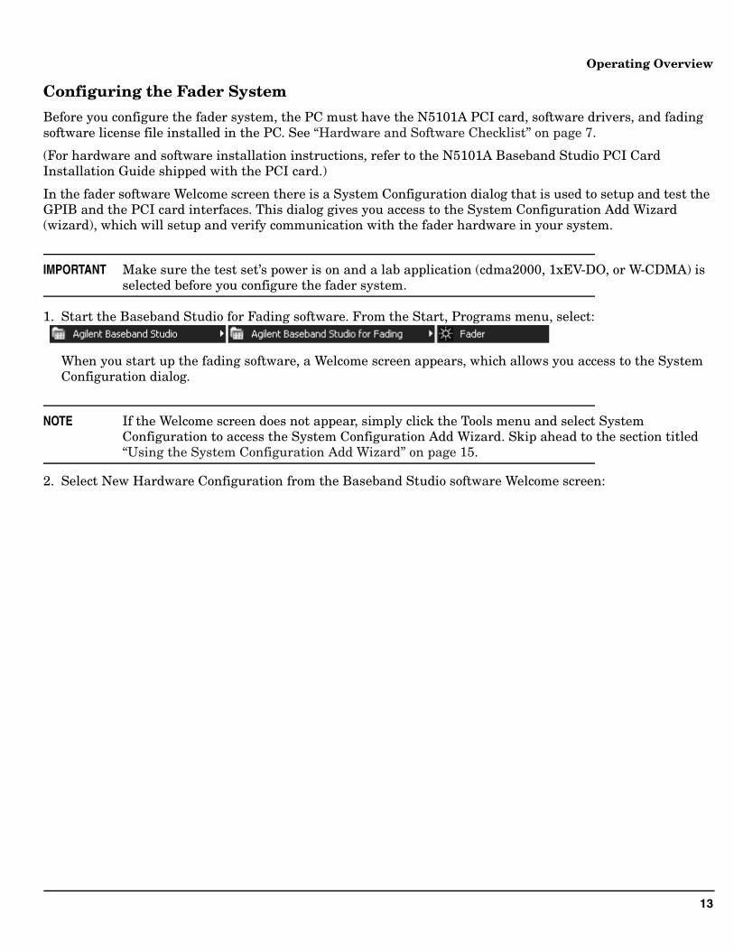
1. Start the Baseband Studio for Fading software. From the Start, Programs menu, select:
When you start up the fading software, a Welcome screen appears, which allows you access to the System Configuration dialog.
NOTE If the Welcome screen does not appear, simply click the Tools menu and select System Configuration to access the System Configuration Add Wizard. Skip ahead to the section titled “Using the System Configuration Add Wizard” on page 15.
2. Select New Hardware Configuration from the Baseband Studio software Welcome screen:
14
Operating Overview
3. Unless you plan to identify a new hardware configuration next time you start up the fading software, it is recommended that you select the “Don’t show this dialog at startup” checkbox. The System Configuration dialog can always be accessed from the Tools menu.
4. Click OK.
Selecting this checkbox is optional
15
Operating Overview
Using the System Configuration Add Wizard
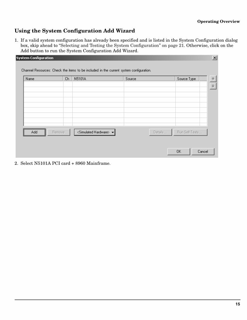
1. If a valid system configuration has already been specified and is listed in the System Configuration dialog box, skip ahead to “Selecting and Testing the System Configuration” on page 21. Otherwise, click on the Add button to run the System Configuration Add Wizard.
2. Select N5101A PCI card + 8960 Mainframe.
16
Operating Overview
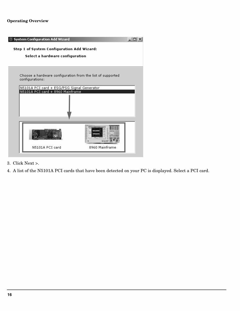
3. Click Next >.
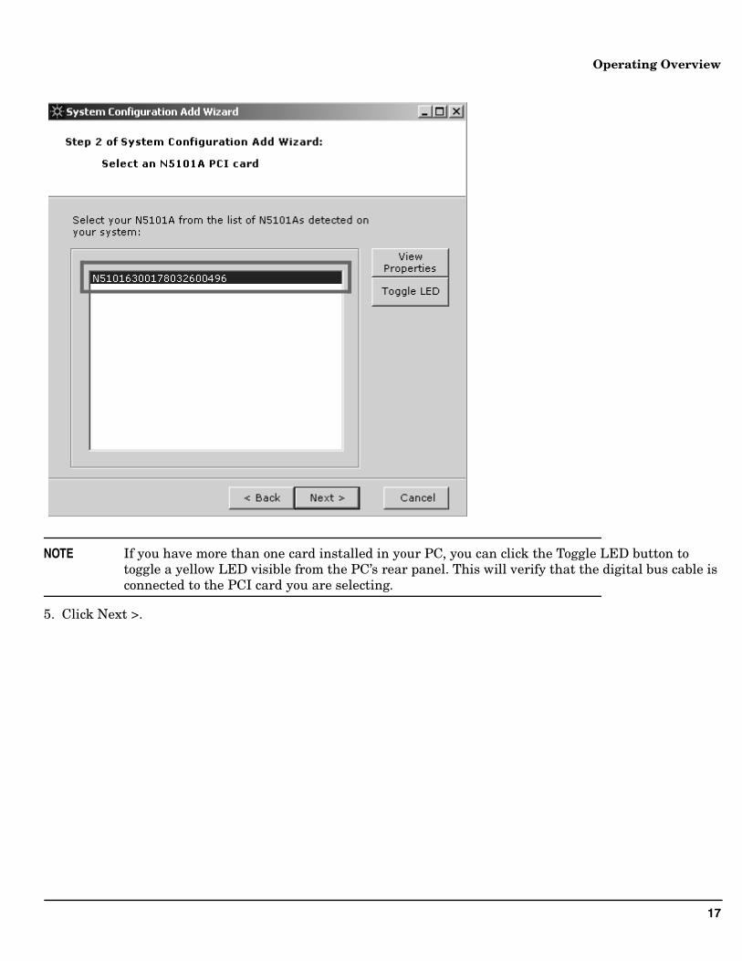
4. A list of the N5101A PCI cards that have been detected on your PC is displayed. Select a PCI card.
17
Operating Overview
NOTE If you have more than one card installed in your PC, you can click the Toggle LED button to toggle a yellow LED visible from the PC’s rear panel. This will verify that the digital bus cable is connected to the PCI card you are selecting.
5. Click Next >.
18
Operating Overview
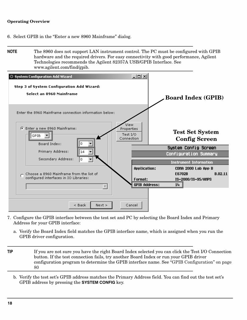
6. Select GPIB in the “Enter a new 8960 Mainframe” dialog.
NOTE The 8960 does not support LAN instrument control. The PC must be configured with GPIB hardware and the required drivers. For easy connectivity with good performance, Agilent Technologies recommends the Agilent 82357A USB/GPIB Interface. See www.agilent.com/find/gpib.
7. Configure the GPIB interface between the test set and PC by selecting the Board Index and Primary Address for your GPIB interface:
a. Verify the Board Index field matches the GPIB interface name, which is assigned when you run the GPIB driver configuration.
TIP If you are not sure you have the right Board Index selected you can click the Test I/O Connection button. If the test connection fails, try another Board Index or run your GPIB driver configuration program to determine the GPIB interface name. See “GPIB Configuration” on page 80
b. Verify the test set’s GPIB address matches the Primary Address field. You can find out the test set’s GPIB address by pressing the SYSTEM CONFIG key.
Test Set SystemConfig Screen
Board Index (GPIB)
19
Operating Overview
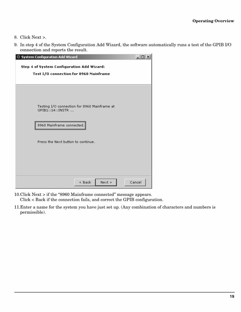
8. Click Next >.
9. In step 4 of the System Configuration Add Wizard, the software automatically runs a test of the GPIB I/O connection and reports the result.
10.Click Next > if the “8960 Mainframe connected” message appears.Click < Back if the connection fails, and correct the GPIB configuration.
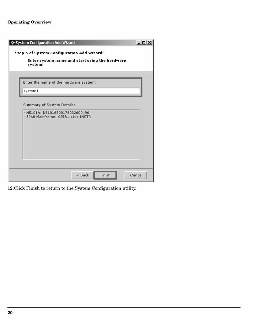
11.Enter a name for the system you have just set up. (Any combination of characters and numbers is permissible).
20
Operating Overview
12.Click Finish to return to the System Configuration utility.
21
Operating Overview
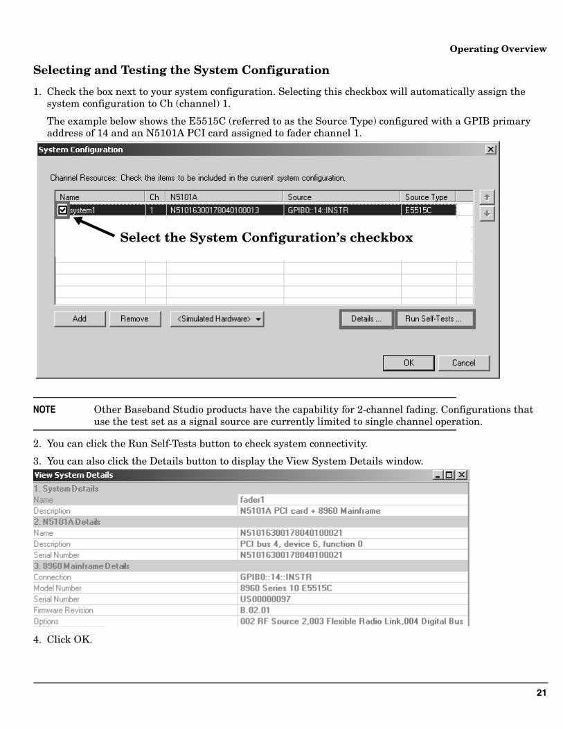
Selecting and Testing the System Configuration
1. Check the box next to your system configuration. Selecting this checkbox will automatically assign the system configuration to Ch (channel) 1.
The example below shows the E5515C (referred to as the Source Type) configured with a GPIB primary address of 14 and an N5101A PCI card assigned to fader channel 1.
NOTE Other Baseband Studio products have the capability for 2-channel fading. Configurations that use the test set as a signal source are currently limited to single channel operation.
2. You can click the Run Self-Tests button to check system connectivity.
3. You can also click the Details button to display the View System Details window.
4. Click OK.
Select the System Configuration’s checkbox
22
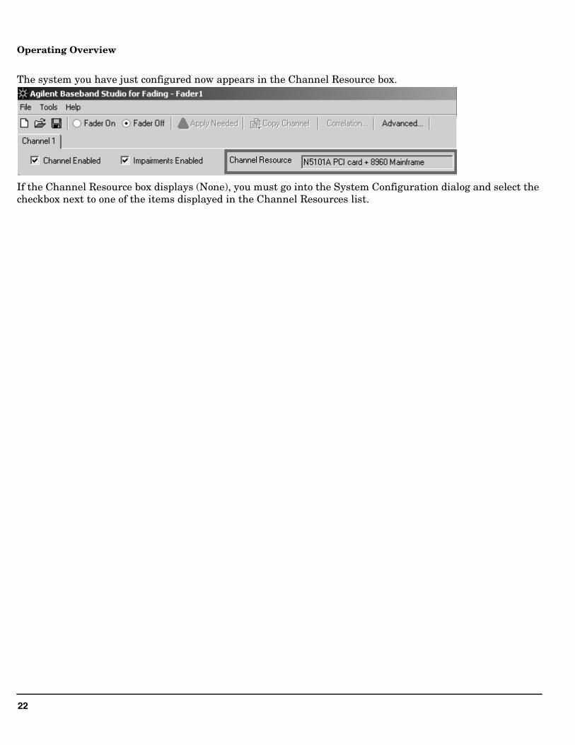
Operating Overview
The system you have just configured now appears in the Channel Resource box.
If the Channel Resource box displays (None), you must go into the System Configuration dialog and select the checkbox next to one of the items displayed in the Channel Resources list.

23
Operating Overview
24
Faded Test Example Procedures
Faded Test Example ProceduresThe following examples detail how to perform faded tests on wireless devices as defined by the 3GPP and 3GPP2 test specifications, using the E5515C Fading Solution.
• “Testing a cdma2000 Mobile Station with a Faded Channel” on page 25
• “Testing a W-CDMA UE with a Faded Channel” on page 38
• “Testing an 1xEV-DO Access Terminal with a Faded Channel” on page 50
25
Faded Test Example Procedures
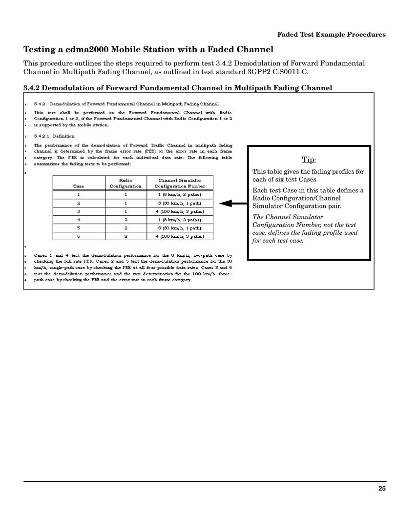
Testing a cdma2000 Mobile Station with a Faded Channel
This procedure outlines the steps required to perform test 3.4.2 Demodulation of Forward Fundamental Channel in Multipath Fading Channel, as outlined in test standard 3GPP2 C.S0011 C.
3.4.2 Demodulation of Forward Fundamental Channel in Multipath Fading Channel
Tip:
This table gives the fading profiles for each of six test Cases.
Each test Case in this table defines a Radio Configuration/Channel Simulator Configuration pair.
The Channel Simulator Configuration Number, not the test case, defines the fading profile used for each test case.
26
Faded Test Example Procedures
3.4.2.2 Method of Measurement
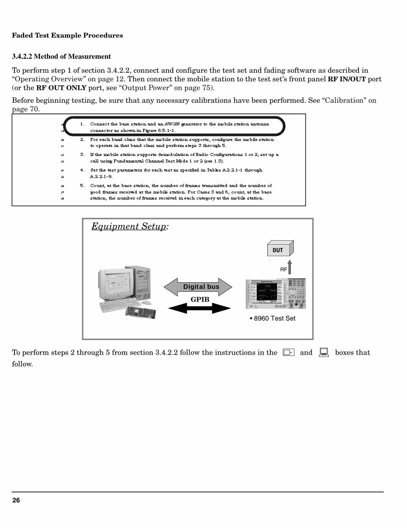
To perform step 1 of section 3.4.2.2, connect and configure the test set and fading software as described in “Operating Overview” on page 12. Then connect the mobile station to the test set’s front panel RF IN/OUT port (or the RF OUT ONLY port, see “Output Power” on page 75).
Before beginning testing, be sure that any necessary calibrations have been performed. See “Calibration” on page 70.
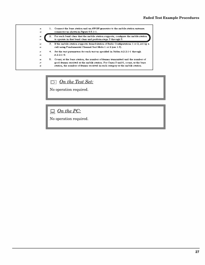
To perform steps 2 through 5 from section 3.4.2.2 follow the instructions in the and boxes that
follow.
• 8960 Test Set
Digital busDigital bus
Analog I/Q RF
DUTDUT
Equipment Setup:
GPIB
27
Faded Test Example Procedures
No operation required.
On the Test Set:
No operation required.
On the PC:
28
Faded Test Example Procedures
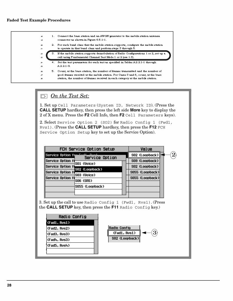
1. Set up Cell Parameters (System ID, Network ID). (Press the CALL SETUP hardkey, then press the left side More key to display the 2 of X menu. Press the F2 Cell Info, then F2 Cell Parameters keys).
2. Select Service Option 2 (SO2) for Radio Config 1 (Fwd1, Rvs1). (Press the CALL SETUP hardkey, then press the F12 FCH Service Option Setup key to set up the Service Option).
3
2
3. Set up the call to use Radio Config 1 (Fwd1, Rvs1). (Press the CALL SETUP key, then press the F11 Radio Config key.)
On the Test Set:
29
Faded Test Example Procedures
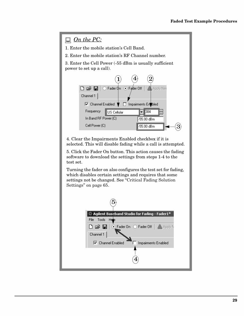
1. Enter the mobile station’s Cell Band.
2. Enter the mobile station’s RF Channel number.
3. Enter the Cell Power (-55 dBm is usually sufficient power to set up a call).
4. Clear the Impairments Enabled checkbox if it is selected. This will disable fading while a call is attempted.
5. Click the Fader On button. This action causes the fading software to download the settings from steps 1-4 to the test set.
Turning the fader on also configures the test set for fading, which disables certain settings and requires that some settings not be changed. See “Critical Fading Solution Settings” on page 65.
1 2
3
5
4
4
On the PC:
30
Faded Test Example Procedures
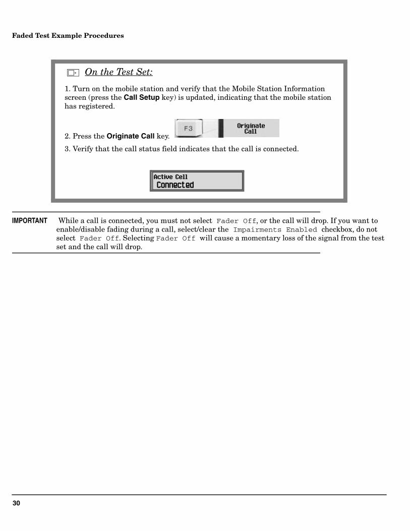
IMPORTANT While a call is connected, you must not select Fader Off, or the call will drop. If you want to enable/disable fading during a call, select/clear the Impairments Enabled checkbox, do not select Fader Off. Selecting Fader Off will cause a momentary loss of the signal from the test set and the call will drop.
1. Turn on the mobile station and verify that the Mobile Station Information screen (press the Call Setup key) is updated, indicating that the mobile station has registered.
2. Press the Originate Call key.
3. Verify that the call status field indicates that the call is connected.
On the Test Set:
31
Faded Test Example Procedures
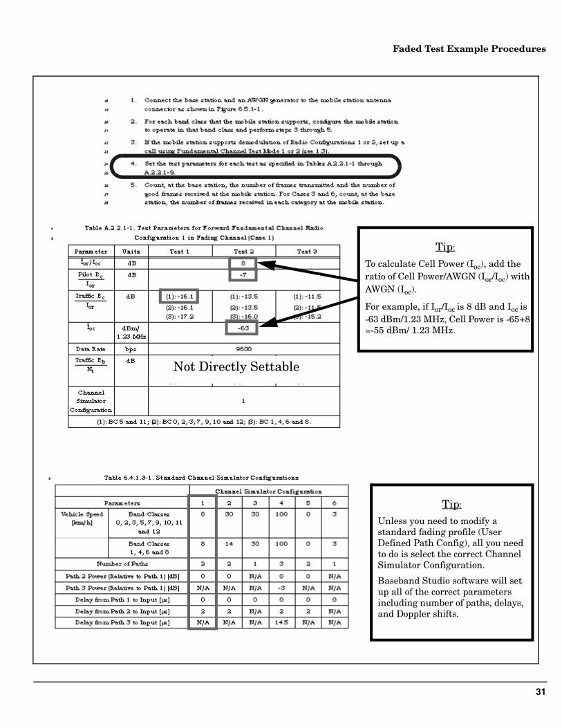
Not Directly Settable
Tip:
To calculate Cell Power (Ioc), add the ratio of Cell Power/AWGN (Ior/Ioc) with AWGN (Ioc).
For example, if Ior/Ioc is 8 dB and Ioc is -63 dBm/1.23 MHz, Cell Power is -65+8 =-55 dBm/ 1.23 MHz.
Tip:
Unless you need to modify a standard fading profile (User Defined Path Config), all you need to do is select the correct Channel Simulator Configuration.
Baseband Studio software will set up all of the correct parameters including number of paths, delays, and Doppler shifts.
32
Faded Test Example Procedures
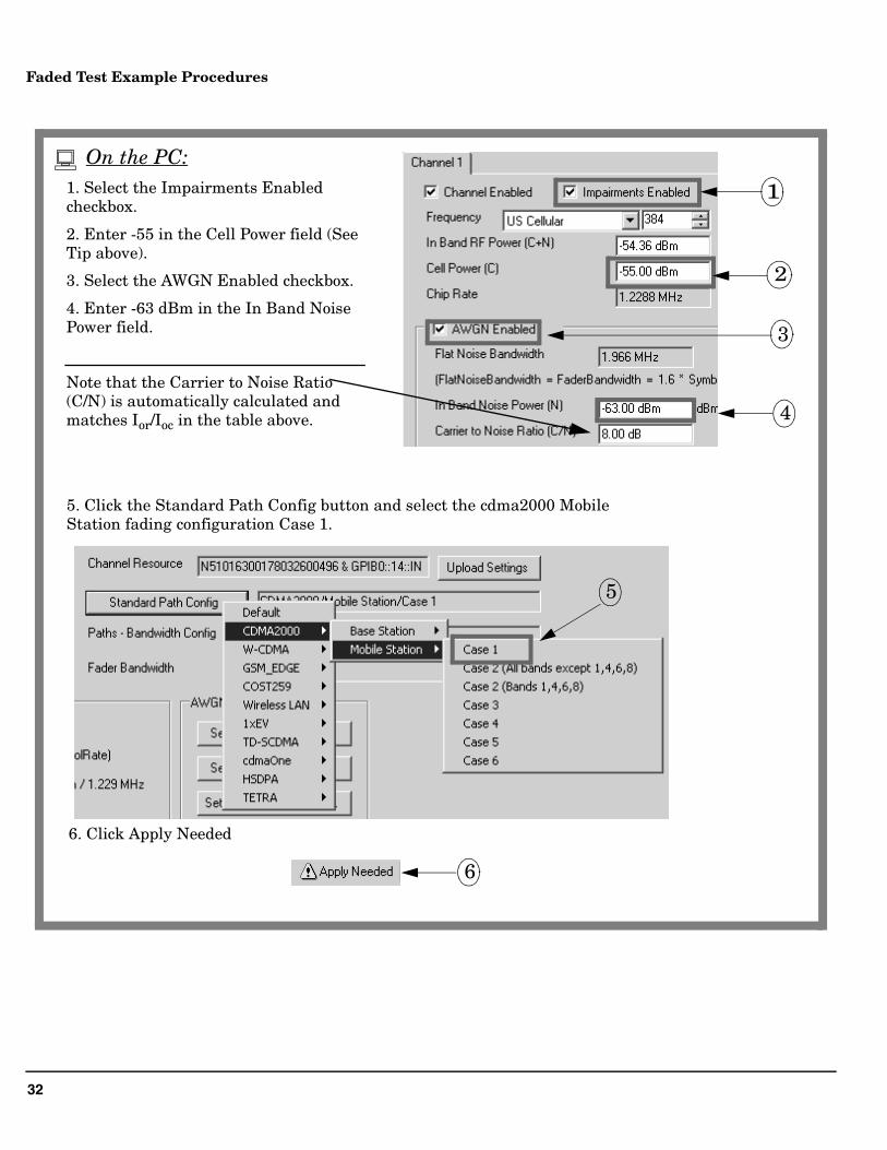
1. Select the Impairments Enabled checkbox.
2. Enter -55 in the Cell Power field (See Tip above).
3. Select the AWGN Enabled checkbox.
4. Enter -63 dBm in the In Band Noise Power field.
Note that the Carrier to Noise Ratio (C/N) is automatically calculated and matches Ior/Ioc in the table above.
1
3
4
2
5
6
5. Click the Standard Path Config button and select the cdma2000 Mobile Station fading configuration Case 1.
6. Click Apply Needed
On the PC:
33
Faded Test Example Procedures
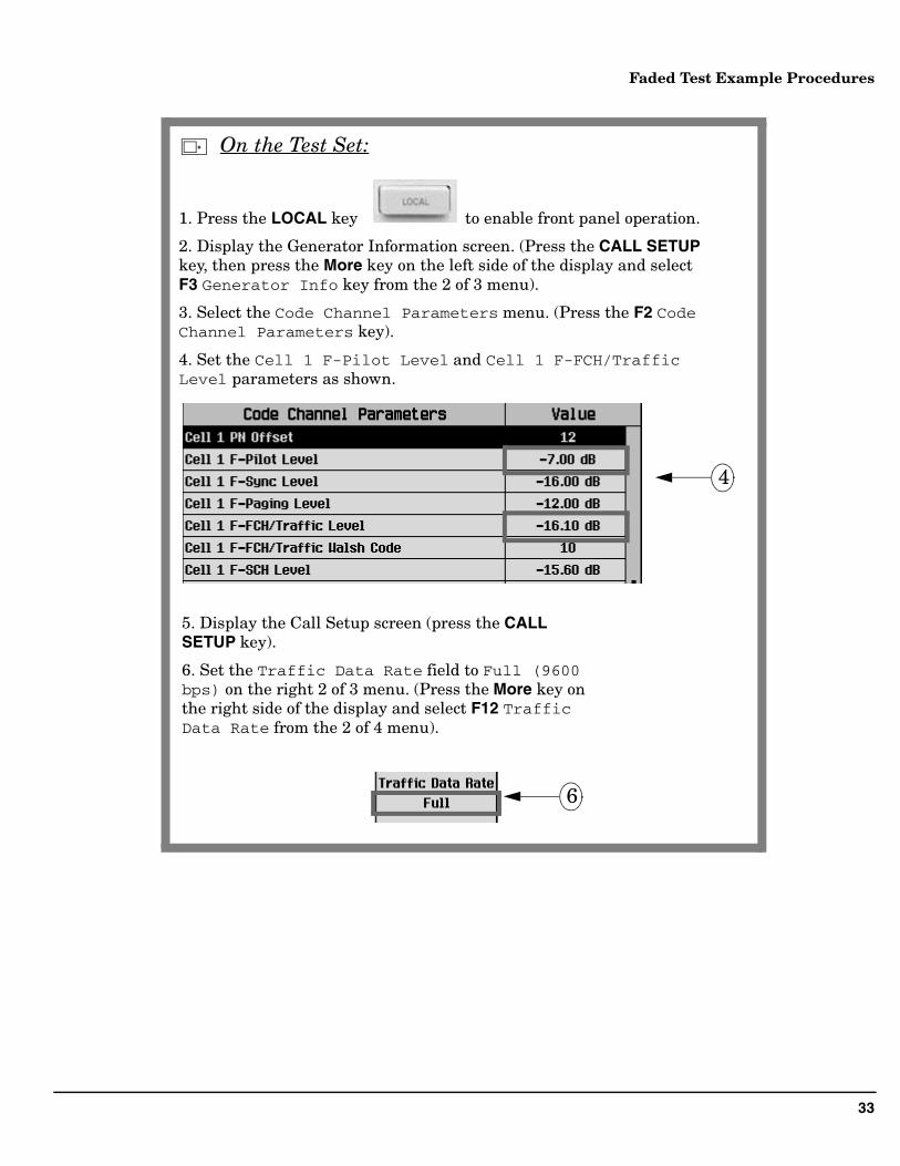
1. Press the LOCAL key to enable front panel operation.
2. Display the Generator Information screen. (Press the CALL SETUP key, then press the More key on the left side of the display and select F3 Generator Info key from the 2 of 3 menu).
3. Select the Code Channel Parameters menu. (Press the F2 Code Channel Parameters key).
4. Set the Cell 1 F-Pilot Level and Cell 1 F-FCH/Traffic Level parameters as shown.
4
5. Display the Call Setup screen (press the CALL SETUP key).
6. Set the Traffic Data Rate field to Full (9600 bps) on the right 2 of 3 menu. (Press the More key on the right side of the display and select F12 Traffic Data Rate from the 2 of 4 menu).
6
On the Test Set:
34
Faded Test Example Procedures
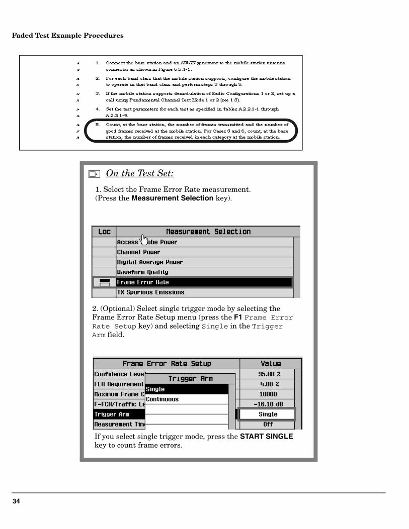
1. Select the Frame Error Rate measurement. (Press the Measurement Selection key).
2. (Optional) Select single trigger mode by selecting the Frame Error Rate Setup menu (press the F1 Frame Error Rate Setup key) and selecting Single in the Trigger Arm field.
If you select single trigger mode, press the START SINGLE key to count frame errors.
On the Test Set:
35
Faded Test Example Procedures
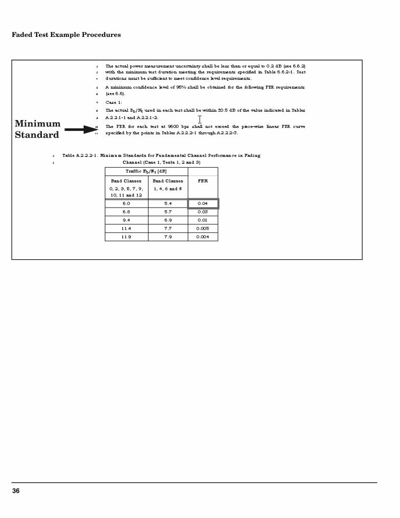
3.4.2.3 Minimum Standard
Tip:
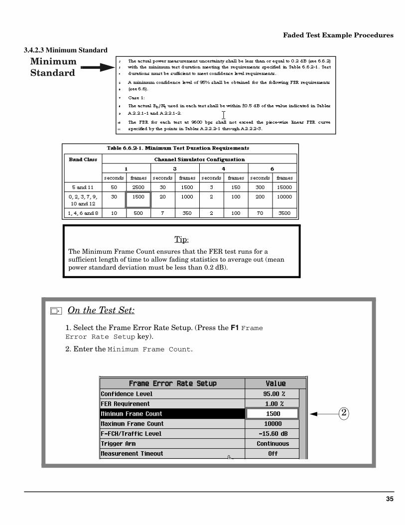
The Minimum Frame Count ensures that the FER test runs for a sufficient length of time to allow fading statistics to average out (mean power standard deviation must be less than 0.2 dB).
Minimum Standard
1. Select the Frame Error Rate Setup. (Press the F1 Frame Error Rate Setup key).
2. Enter the Minimum Frame Count.
2
On the Test Set:
36
Faded Test Example Procedures
Minimum Standard
37
Faded Test Example Procedures
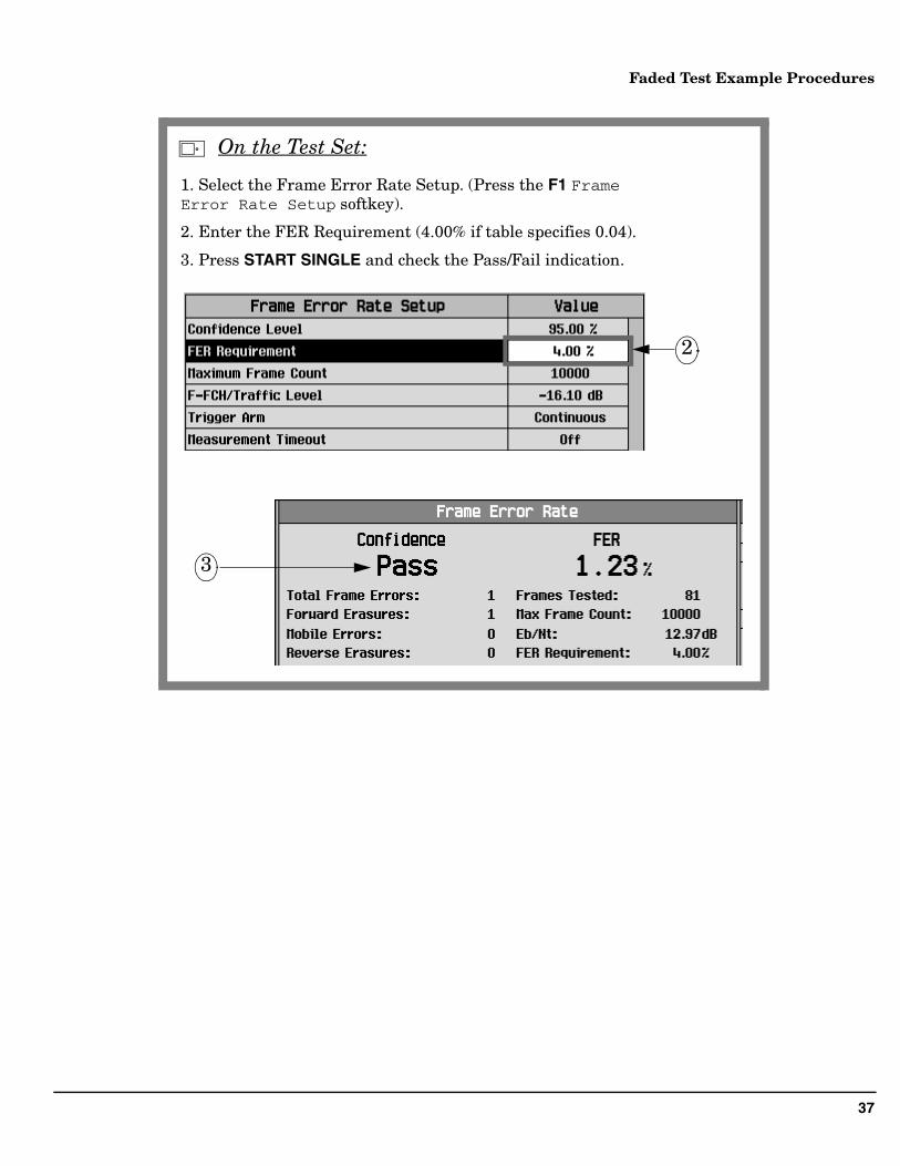
1. Select the Frame Error Rate Setup. (Press the F1 Frame Error Rate Setup softkey).
2. Enter the FER Requirement (4.00% if table specifies 0.04).
3. Press START SINGLE and check the Pass/Fail indication.
2
3
On the Test Set:
38
Faded Test Example Procedures
Testing a W-CDMA UE with a Faded Channel
This section outlines the steps required to perform 3GPP TS 34.121 7.3 Demodulation of DCH in Multi-path Fading Propagation Conditions using the E5515C Fading Solution.
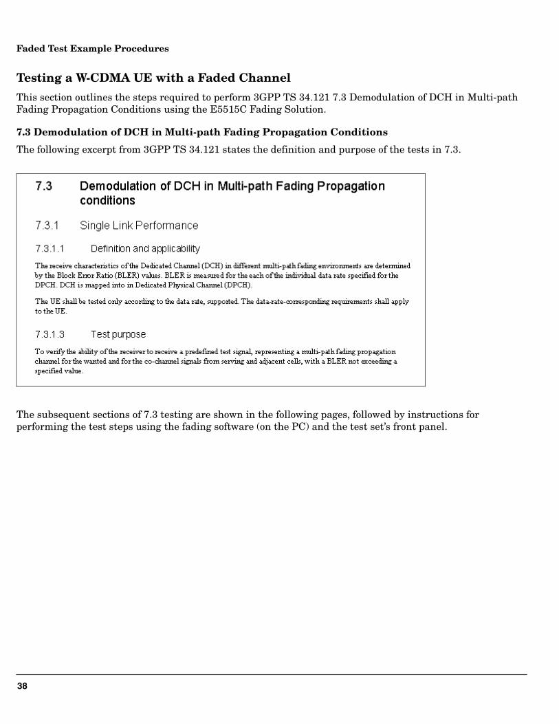
7.3 Demodulation of DCH in Multi-path Fading Propagation Conditions
The following excerpt from 3GPP TS 34.121 states the definition and purpose of the tests in 7.3.
The subsequent sections of 7.3 testing are shown in the following pages, followed by instructions for performing the test steps using the fading software (on the PC) and the test set’s front panel.
39
Faded Test Example Procedures
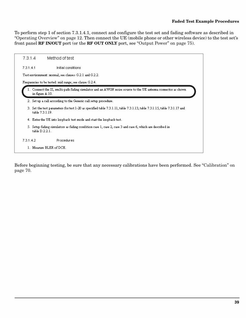
To perform step 1 of section 7.3.1.4.1, connect and configure the test set and fading software as described in “Operating Overview” on page 12. Then connect the UE (mobile phone or other wireless device) to the test set’s front panel RF IN/OUT port (or the RF OUT ONLY port, see “Output Power” on page 75).
Before beginning testing, be sure that any necessary calibrations have been performed. See “Calibration” on page 70.
40
Faded Test Example Procedures
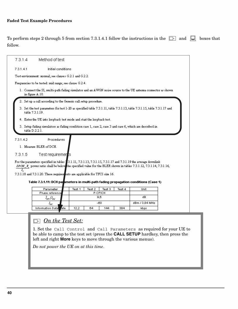
To perform steps 2 through 5 from section 7.3.1.4.1 follow the instructions in the and boxes that
follow.
On the Test Set:1. Set the Call Control and Call Parameters as required for your UE to be able to camp to the test set (press the CALL SETUP hardkey, then press the left and right More keys to move through the various menus).
Do not power the UE on at this time.
41
Faded Test Example Procedures
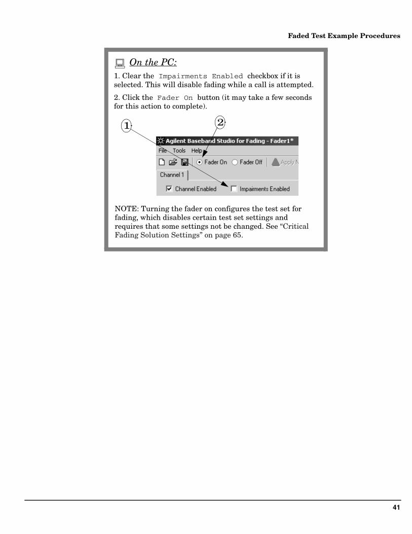
1. Clear the Impairments Enabled checkbox if it is selected. This will disable fading while a call is attempted.
2. Click the Fader On button (it may take a few seconds for this action to complete).
2
On the PC:
NOTE: Turning the fader on configures the test set for fading, which disables certain test set settings and requires that some settings not be changed. See “Critical Fading Solution Settings” on page 65.
1
42
Faded Test Example Procedures
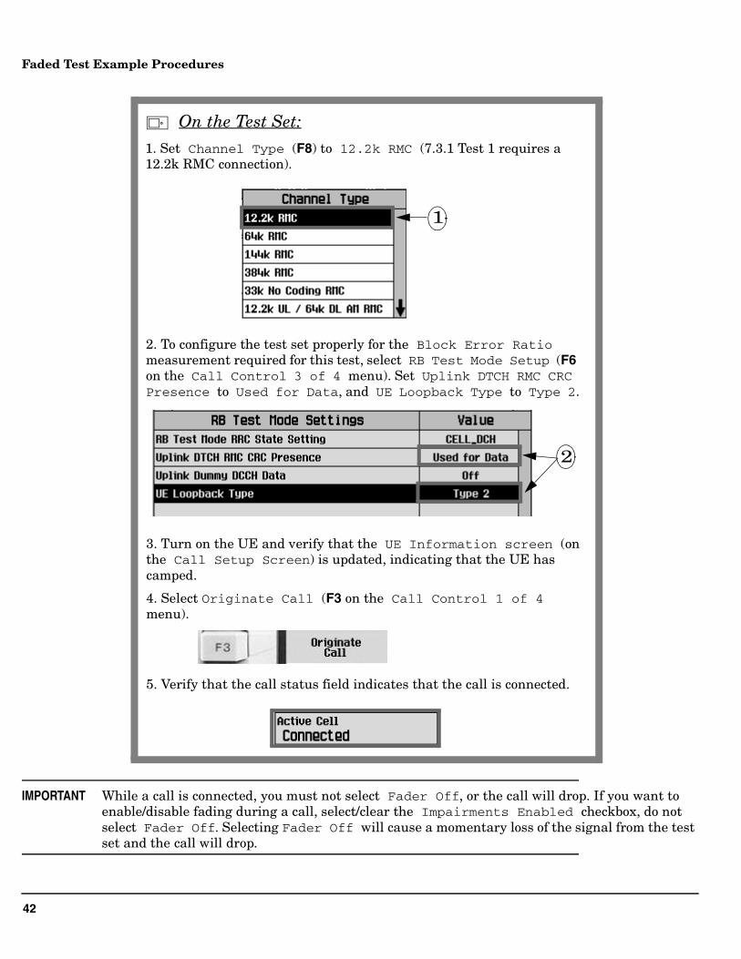
IMPORTANT While a call is connected, you must not select Fader Off, or the call will drop. If you want to enable/disable fading during a call, select/clear the Impairments Enabled checkbox, do not select Fader Off. Selecting Fader Off will cause a momentary loss of the signal from the test set and the call will drop.
1. Set Channel Type (F8) to 12.2k RMC (7.3.1 Test 1 requires a 12.2k RMC connection).
2
2. To configure the test set properly for the Block Error Ratio measurement required for this test, select RB Test Mode Setup (F6 on the Call Control 3 of 4 menu). Set Uplink DTCH RMC CRC Presence to Used for Data, and UE Loopback Type to Type 2.
3. Turn on the UE and verify that the UE Information screen (on the Call Setup Screen) is updated, indicating that the UE has camped.
4. Select Originate Call (F3 on the Call Control 1 of 4 menu).
5. Verify that the call status field indicates that the call is connected.
1
On the Test Set:
43
Faded Test Example Procedures
To configure the power and noise levels of the faded channel as required for 7.3.1 Test 1, follow the instructions
in the and boxes on the following pages.
44
Faded Test Example Procedures
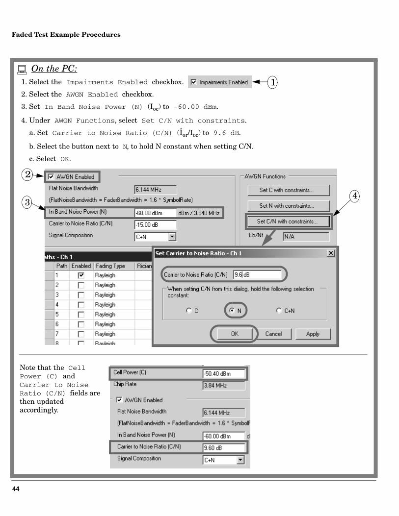
1. Select the Impairments Enabled checkbox.
2. Select the AWGN Enabled checkbox.
3. Set In Band Noise Power (N) (Ioc) to -60.00 dBm.
4. Under AWGN Functions, select Set C/N with constraints.
a. Set Carrier to Noise Ratio (C/N) (Îor/Ioc) to 9.6 dB.
b. Select the button next to N, to hold N constant when setting C/N.
c. Select OK.
34
2
Note that the Cell Power (C) and Carrier to Noise Ratio (C/N) fields are then updated accordingly.
1
On the PC:
45
Faded Test Example Procedures
5
6
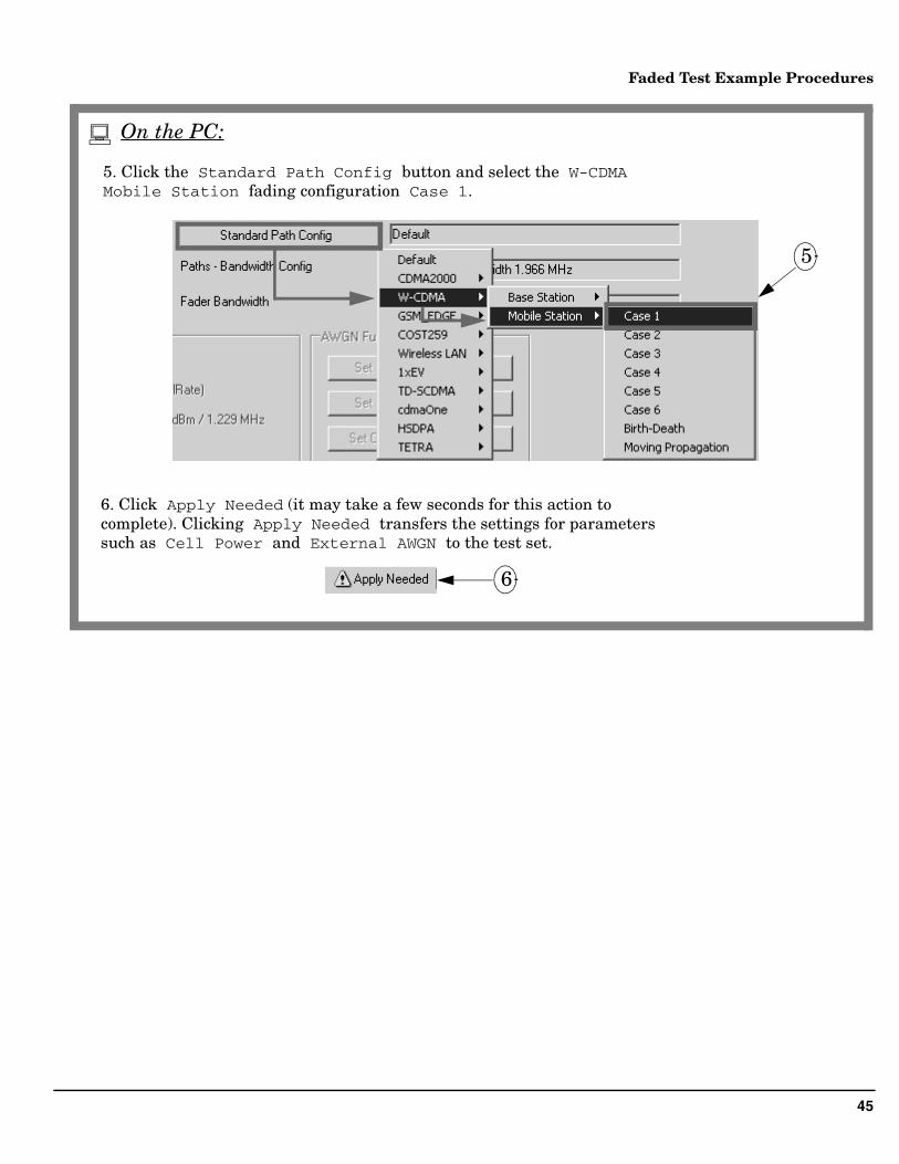
5. Click the Standard Path Config button and select the W-CDMA Mobile Station fading configuration Case 1.
6. Click Apply Needed (it may take a few seconds for this action to complete). Clicking Apply Needed transfers the settings for parameters such as Cell Power and External AWGN to the test set.
On the PC:
46
Faded Test Example Procedures
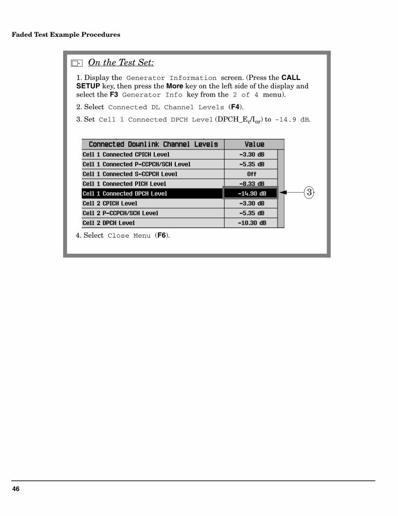
1. Display the Generator Information screen. (Press the CALL SETUP key, then press the More key on the left side of the display and select the F3 Generator Info key from the 2 of 4 menu).
2. Select Connected DL Channel Levels (F4).
3. Set Cell 1 Connected DPCH Level (DPCH_Ec/Ior) to -14.9 dB.
3
4. Select Close Menu (F6).
On the Test Set:
47
Faded Test Example Procedures
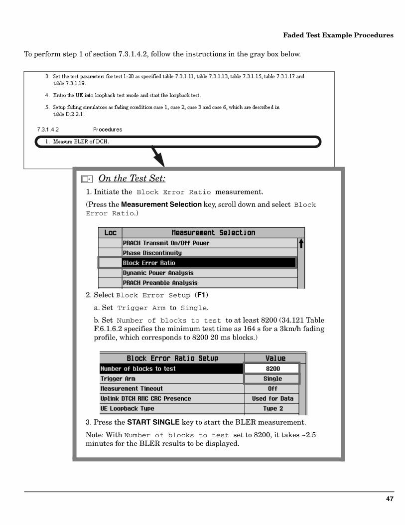
To perform step 1 of section 7.3.1.4.2, follow the instructions in the gray box below.
1. Initiate the Block Error Ratio measurement.
(Press the Measurement Selection key, scroll down and select Block Error Ratio.)
2. Select Block Error Setup (F1)
a. Set Trigger Arm to Single.
b. Set Number of blocks to test to at least 8200 (34.121 Table F.6.1.6.2 specifies the minimum test time as 164 s for a 3km/h fading profile, which corresponds to 8200 20 ms blocks.)
3. Press the START SINGLE key to start the BLER measurement.
Note: With Number of blocks to test set to 8200, it takes ~2.5 minutes for the BLER results to be displayed.
On the Test Set:
48
Faded Test Example Procedures
Compare your measured BLER result with the test requirements of section 7.3.1.5.
1. Verify that the Block Error Ratio result is less than 10-2 (1%).
On the Test Set:
49
Faded Test Example Procedures
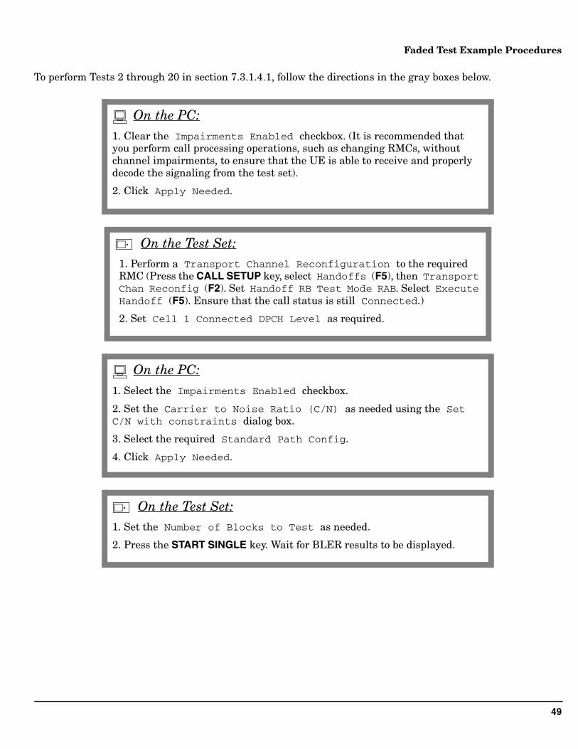
To perform Tests 2 through 20 in section 7.3.1.4.1, follow the directions in the gray boxes below.
1. Clear the Impairments Enabled checkbox. (It is recommended that you perform call processing operations, such as changing RMCs, without channel impairments, to ensure that the UE is able to receive and properly decode the signaling from the test set).
2. Click Apply Needed.
On the PC:
1. Perform a Transport Channel Reconfiguration to the required RMC (Press the CALL SETUP key, select Handoffs (F5), then Transport Chan Reconfig (F2). Set Handoff RB Test Mode RAB. Select Execute Handoff (F5). Ensure that the call status is still Connected.)
2. Set Cell 1 Connected DPCH Level as required.
On the Test Set:
1. Select the Impairments Enabled checkbox.
2. Set the Carrier to Noise Ratio (C/N) as needed using the Set C/N with constraints dialog box.
3. Select the required Standard Path Config.
4. Click Apply Needed.
On the PC:
1. Set the Number of Blocks to Test as needed.
2. Press the START SINGLE key. Wait for BLER results to be displayed.
On the Test Set:
50
Faded Test Example Procedures
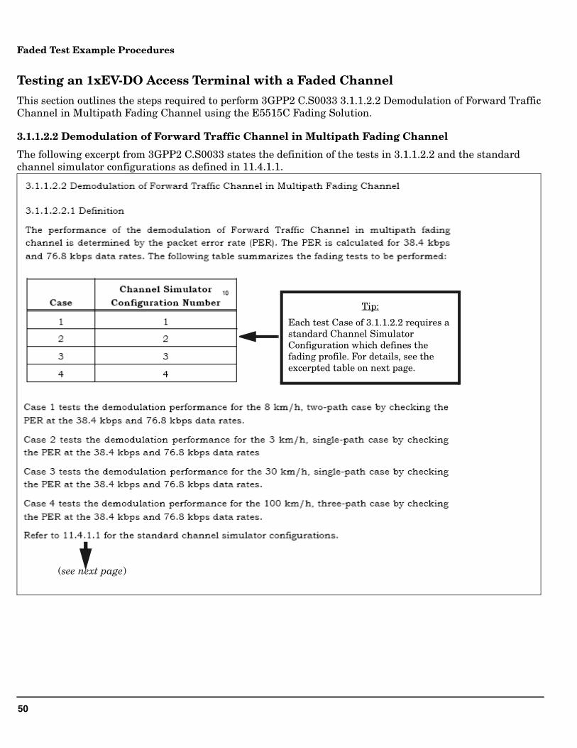
Testing an 1xEV-DO Access Terminal with a Faded Channel
This section outlines the steps required to perform 3GPP2 C.S0033 3.1.1.2.2 Demodulation of Forward Traffic Channel in Multipath Fading Channel using the E5515C Fading Solution.
3.1.1.2.2 Demodulation of Forward Traffic Channel in Multipath Fading Channel
The following excerpt from 3GPP2 C.S0033 states the definition of the tests in 3.1.1.2.2 and the standard channel simulator configurations as defined in 11.4.1.1.
(see next page)
Tip:
Each test Case of 3.1.1.2.2 requires a standard Channel Simulator Configuration which defines the fading profile. For details, see the excerpted table on next page.
51
Faded Test Example Procedures
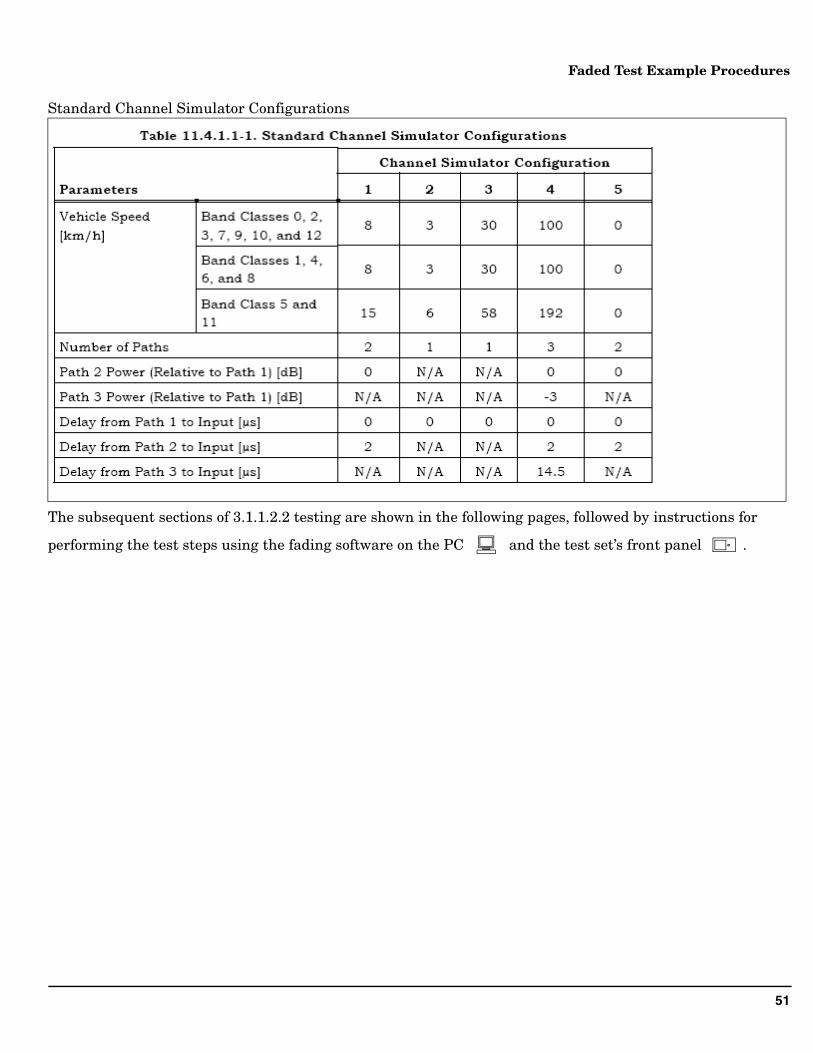
Standard Channel Simulator Configurations
The subsequent sections of 3.1.1.2.2 testing are shown in the following pages, followed by instructions for
performing the test steps using the fading software on the PC and the test set’s front panel .
52
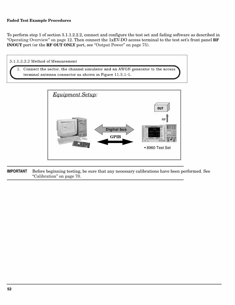
Faded Test Example Procedures
To perform step 1 of section 3.1.1.2.2.2, connect and configure the test set and fading software as described in “Operating Overview” on page 12. Then connect the 1xEV-DO access terminal to the test set’s front panel RF IN/OUT port (or the RF OUT ONLY port, see “Output Power” on page 75).
IMPORTANT Before beginning testing, be sure that any necessary calibrations have been performed. See “Calibration” on page 70.
• 8960 Test Set
Digital busDigital bus
Analog I/Q RF
DUTDUT
Equipment Setup:
GPIB
53
Faded Test Example Procedures
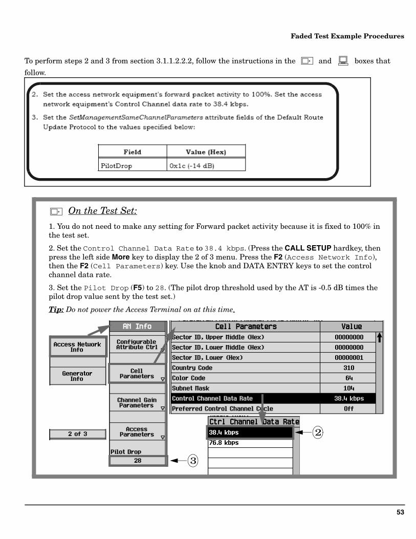
To perform steps 2 and 3 from section 3.1.1.2.2.2, follow the instructions in the and boxes that
follow.
1. You do not need to make any setting for Forward packet activity because it is fixed to 100% in the test set.
2. Set the Control Channel Data Rate to 38.4 kbps. (Press the CALL SETUP hardkey, then press the left side More key to display the 2 of 3 menu. Press the F2 (Access Network Info), then the F2 (Cell Parameters) key. Use the knob and DATA ENTRY keys to set the control channel data rate.
3. Set the Pilot Drop (F5) to 28. (The pilot drop threshold used by the AT is -0.5 dB times the pilot drop value sent by the test set.)
Tip: Do not power the Access Terminal on at this time.
On the Test Set:
3
2
54
Faded Test Example Procedures
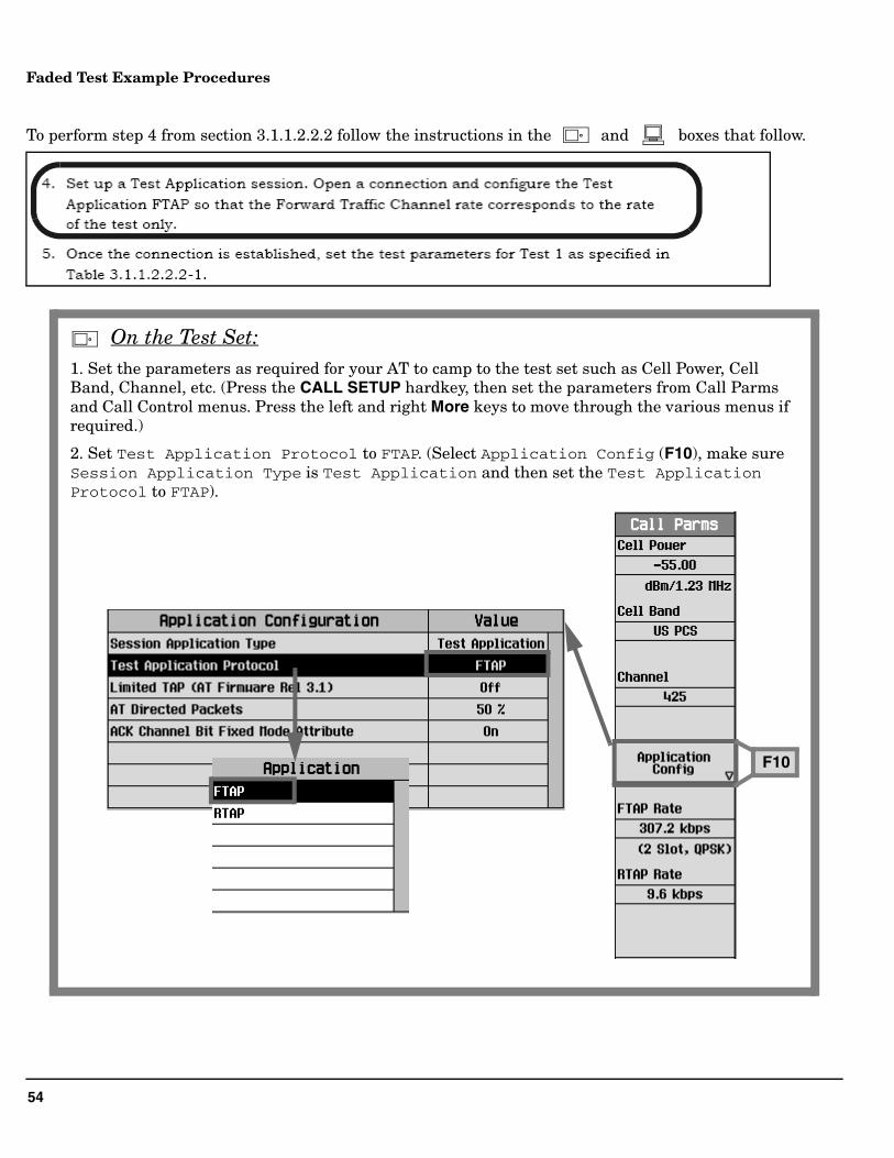
To perform step 4 from section 3.1.1.2.2.2 follow the instructions in the and boxes that follow.
On the Test Set:1. Set the parameters as required for your AT to camp to the test set such as Cell Power, Cell Band, Channel, etc. (Press the CALL SETUP hardkey, then set the parameters from Call Parms and Call Control menus. Press the left and right More keys to move through the various menus if required.)
2. Set Test Application Protocol to FTAP. (Select Application Config (F10), make sure Session Application Type is Test Application and then set the Test Application Protocol to FTAP).
F10
55
Faded Test Example Procedures
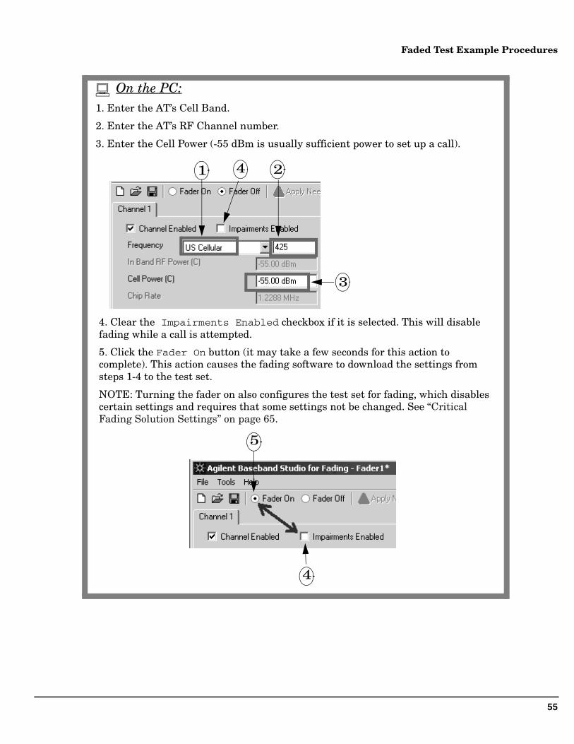
1. Enter the AT’s Cell Band.
2. Enter the AT’s RF Channel number.
3. Enter the Cell Power (-55 dBm is usually sufficient power to set up a call).
4. Clear the Impairments Enabled checkbox if it is selected. This will disable fading while a call is attempted.
5. Click the Fader On button (it may take a few seconds for this action to complete). This action causes the fading software to download the settings from steps 1-4 to the test set.
NOTE: Turning the fader on also configures the test set for fading, which disables certain settings and requires that some settings not be changed. See “Critical Fading Solution Settings” on page 65.
1 2
3
5
4
4
On the PC:
56
Faded Test Example Procedures
IMPORTANT While a call is connected, you must not select Fader Off, or the call will drop. If you want to enable/disable fading during a call, select/clear the Impairments Enabled checkbox, do not select Fader Off. Selecting Fader Off will cause a momentary loss of the signal from the test set and the call will drop.
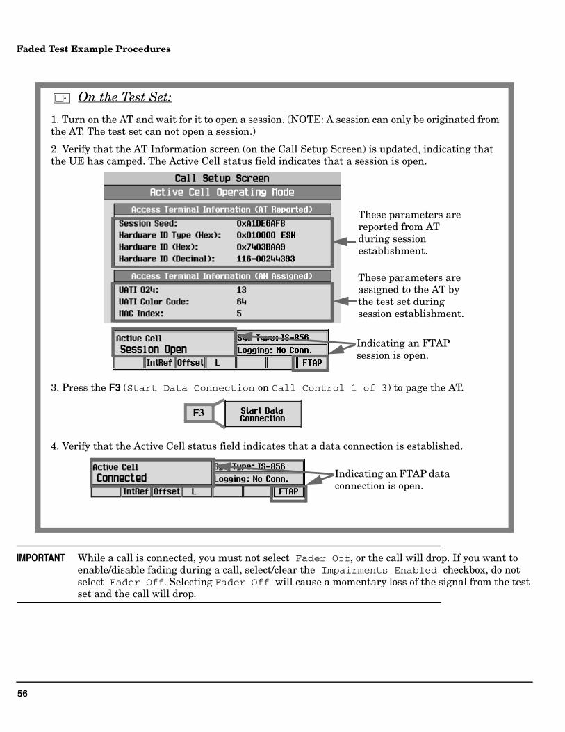
1. Turn on the AT and wait for it to open a session. (NOTE: A session can only be originated from the AT. The test set can not open a session.)
2. Verify that the AT Information screen (on the Call Setup Screen) is updated, indicating that the UE has camped. The Active Cell status field indicates that a session is open.
3. Press the F3 (Start Data Connection on Call Control 1 of 3) to page the AT.
4. Verify that the Active Cell status field indicates that a data connection is established.
These parameters are reported from AT during session establishment.
These parameters are assigned to the AT by the test set during session establishment.
Indicating an FTAP session is open.
F3
Indicating an FTAP data connection is open.
On the Test Set:
57
Faded Test Example Procedures
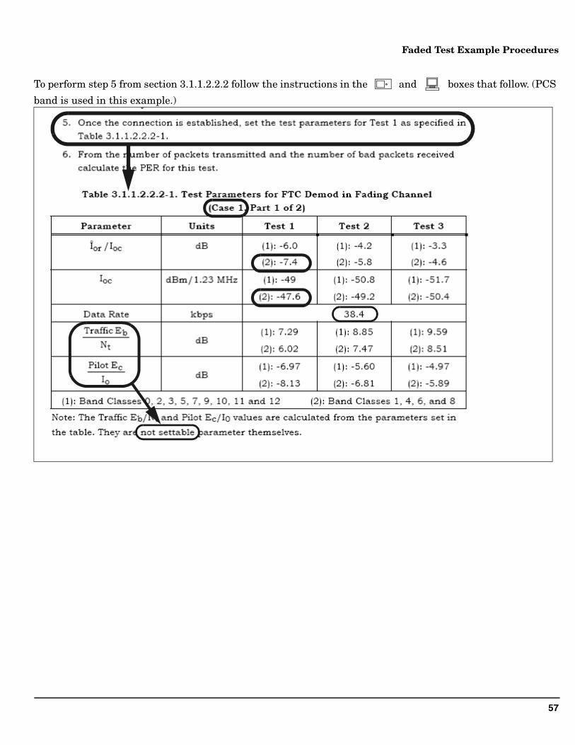
To perform step 5 from section 3.1.1.2.2.2 follow the instructions in the and boxes that follow. (PCS
band is used in this example.)
58
Faded Test Example Procedures
1. Select the Impairments Enabled checkbox.
2. Select the AWGN Enabled checkbox.
3. Set In Band Noise Power (N) (Ioc) to -47.6 dBm.
4. Under AWGN Functions, select Set C/N with constraints.(Set Carrier to Noise Ratio (C/N) (Îor/Ioc) to -7.4 dB. Select the button next to N, to hold N constant when setting C/N. Select OK.)
34
2
Note that the Cell Power (C) and Carrier to Noise Ratio (C/N) fields are then updated accordingly.
1
On the PC:
59
Faded Test Example Procedures
On the PC (continued):
5. Click the Standard Path Config button and select the 1xEV-DO fading configuration Case 1.
Tips:
Unless you need to modify a standard fading profile (User Defined Path Config), all you need to do is to select the correct Channel Simulator Configuration. Baseband Studio software will set up all of the correct parameters including number of paths, delays, and Doppler shifts as specified by standard. The standard channel simulator configurations are excepted on page 51.
6. Click Apply Needed (it may take a few seconds for this action to complete). Clicking Apply Needed transfers the settings for parameters such as Cell Power and External AWGN to the test set.
5
6
60
Faded Test Example Procedures
1. Press the LOCAL key to enable front panel operation.
2. Set FTAP Rate to 38.4 Kbps for Test 1.(Press the CALL SETUP hardkey, then Press the F11 (FTAP Rate) key from Call Parms 1 of 3 menu).
F11
On the Test Set:
61
Faded Test Example Procedures
To perform step 6 from section 3.1.1.2.2.2 follow the instructions in the and boxes that follow.
1. Initiate the Packet Error Rate measurement.
(Press the Measurement Selection key, scroll down and select Packet Error Rate.)
2. Select Packet Error Setup (F1). Set the measurement parameters as required for the Test 1. See the following pages for details.
On the Test Set:
62
Faded Test Example Procedures
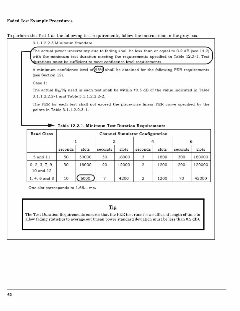
To perform the Test 1 as the following test requirements, follow the instructions in the gray box.
2
Tip:
The Test Duration Requirements ensures that the PER test runs for a sufficient length of time to allow fading statistics to average out (mean power standard deviation must be less than 0.2 dB).
63
Faded Test Example Procedures
64
Faded Test Example Procedures
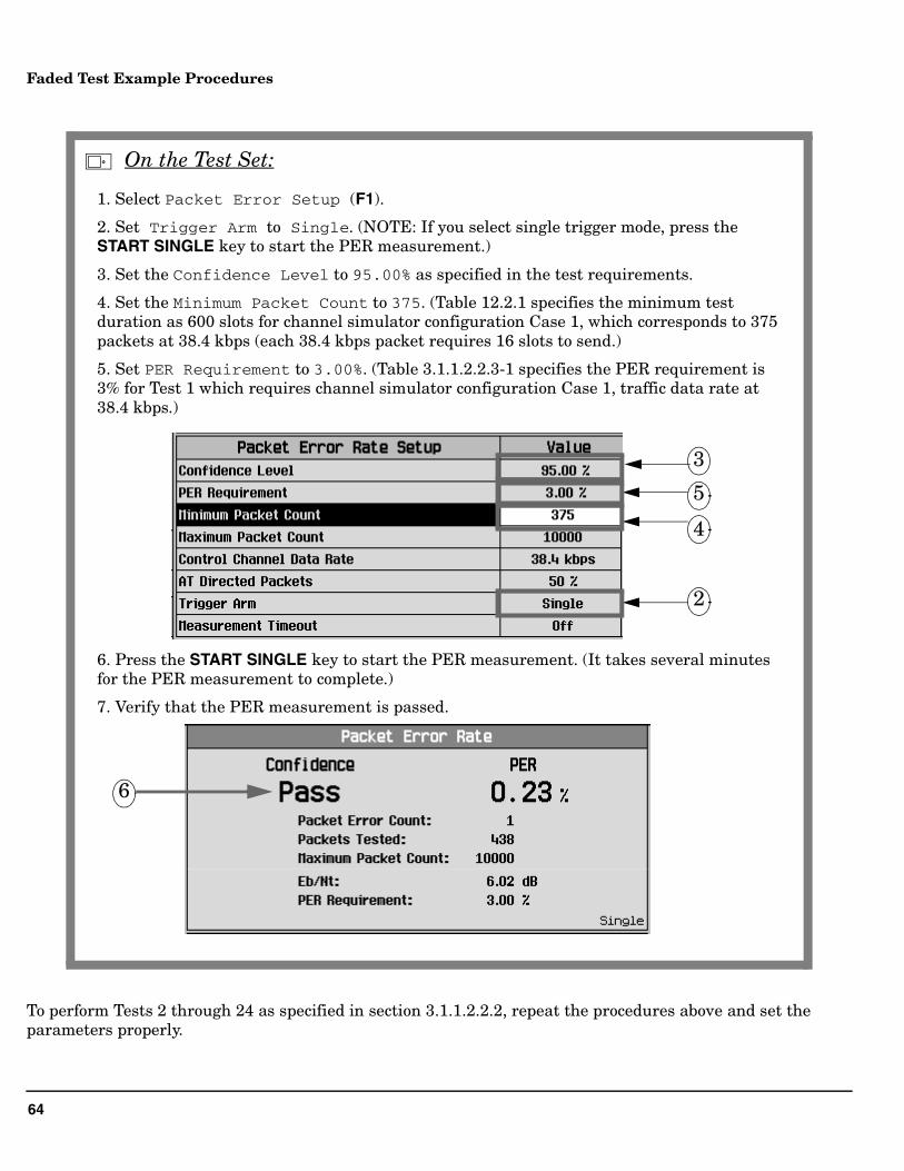
To perform Tests 2 through 24 as specified in section 3.1.1.2.2.2, repeat the procedures above and set the parameters properly.
1. Select Packet Error Setup (F1).
2. Set Trigger Arm to Single. (NOTE: If you select single trigger mode, press the START SINGLE key to start the PER measurement.)
3. Set the Confidence Level to 95.00% as specified in the test requirements.
4. Set the Minimum Packet Count to 375. (Table 12.2.1 specifies the minimum test duration as 600 slots for channel simulator configuration Case 1, which corresponds to 375 packets at 38.4 kbps (each 38.4 kbps packet requires 16 slots to send.)
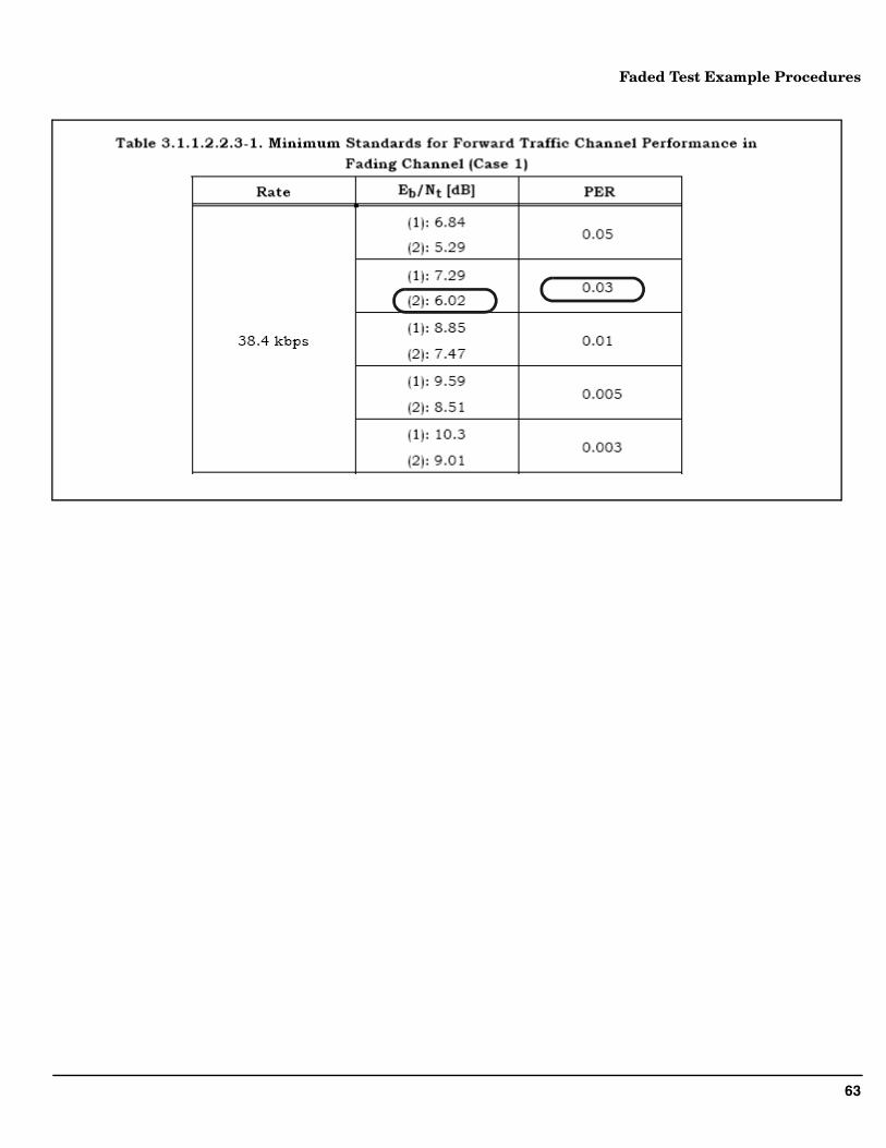
5. Set PER Requirement to 3.00%. (Table 3.1.1.2.2.3-1 specifies the PER requirement is 3% for Test 1 which requires channel simulator configuration Case 1, traffic data rate at 38.4 kbps.)
6. Press the START SINGLE key to start the PER measurement. (It takes several minutes for the PER measurement to complete.)
7. Verify that the PER measurement is passed.
4
5
3
2
6
On the Test Set:
65
Fader System Requirements
Fader System RequirementsThis section provides background operating information and theory of operation for the E5515C Fading Solution (fader).
Critical Fading Solution Settings
Because the fader integrates a PC software application with hardware residing on both the PC and the test set, the fader must function as a test system. During fading, the PC functions as the system controller, sending GPIB commands to the test set.
After the PC has remotely configured the test set for fading, critical settings must not be overridden by manual test set via front panel operation.
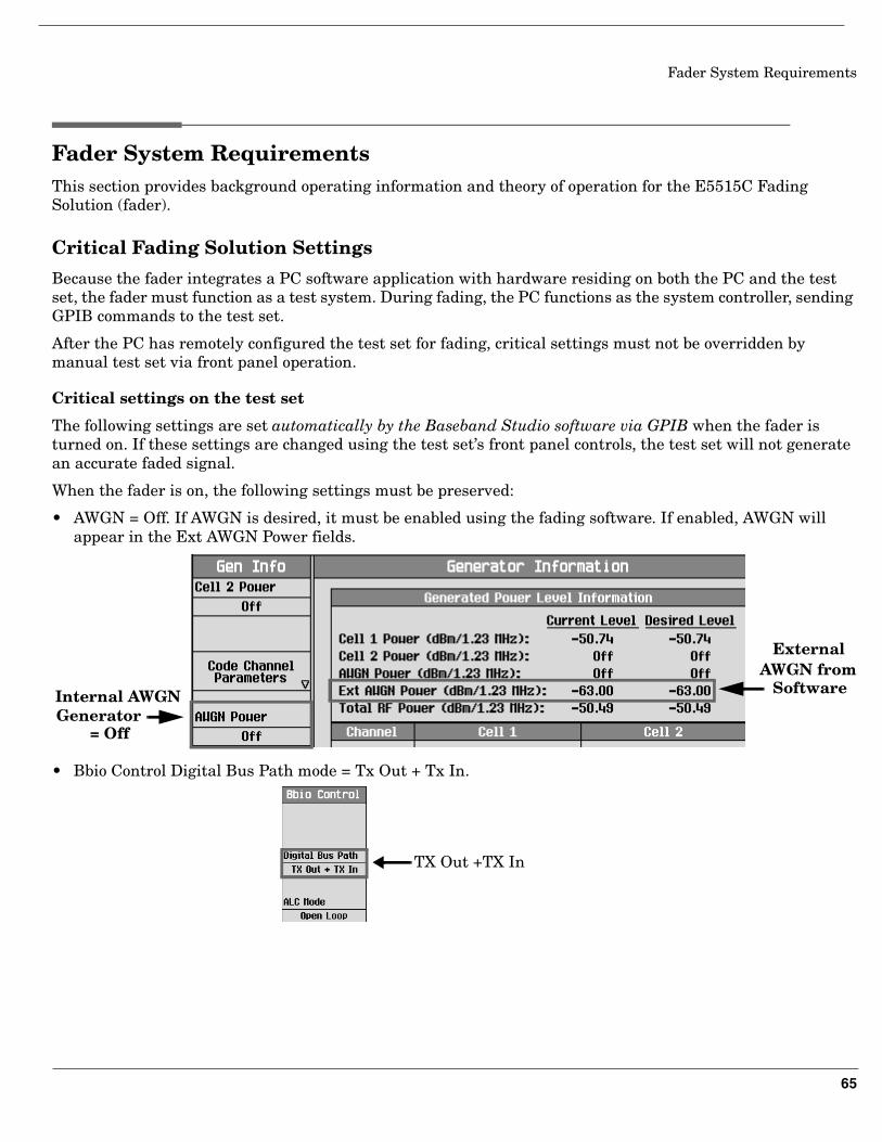
Critical settings on the test set
The following settings are set automatically by the Baseband Studio software via GPIB when the fader is turned on. If these settings are changed using the test set’s front panel controls, the test set will not generate an accurate faded signal.
When the fader is on, the following settings must be preserved:
• AWGN = Off. If AWGN is desired, it must be enabled using the fading software. If enabled, AWGN will appear in the Ext AWGN Power fields.
• Bbio Control Digital Bus Path mode = Tx Out + Tx In.
Internal AWGNGenerator
ExternalAWGN from
Software
= Off
TX Out +TX In
66
Fader System Requirements
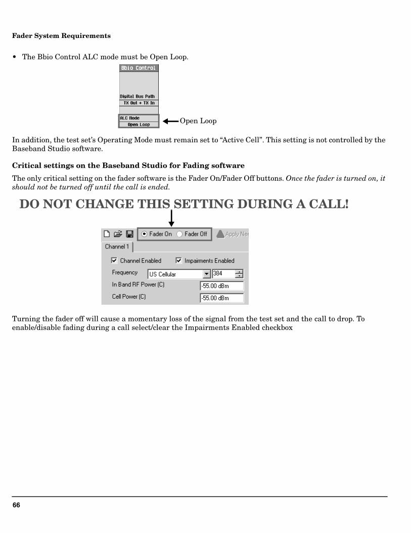
• The Bbio Control ALC mode must be Open Loop.
In addition, the test set’s Operating Mode must remain set to “Active Cell”. This setting is not controlled by the Baseband Studio software.
Critical settings on the Baseband Studio for Fading software
The only critical setting on the fader software is the Fader On/Fader Off buttons. Once the fader is turned on, it should not be turned off until the call is ended.
Turning the fader off will cause a momentary loss of the signal from the test set and the call to drop. To enable/disable fading during a call select/clear the Impairments Enabled checkbox
Open Loop
DO NOT CHANGE THIS SETTING DURING A CALL!
67
Fader System Requirements
Power Level Control During Fading
This section, “Power Level Control During Fading” , provides background information pertaining to the fader’s power level control. It will help you understand the fader’s output signal generation and some of the limitations that can cause the overrange error to be displayed.
When the fader is turned on, the test set’s signal level is controlled differently than when the fader is turned off. Even though all of the necessary configuration changes to the test set are made automatically by the fader software via GPIB, in some cases it may be useful to understand how power levels are affected when the fader is turned on.
Level Accuracy
Normally, the test set uses an automatic level control (ALC) loop to compare detected power with a reference level and feed back the difference to the RF modulator to correct any error.
During faded signal tests, however, the test set’s ALC loop must be open (disabled). This is because the test set’s ALC loop would interpret the effects of fading as signal level error. If the ALC loop were not opened, the faded signal would be distorted since the ALC bandwidth is much wider than the relatively narrow bandwidth of typical fading patterns.
When the ALC loop is open, a calibration routine must be performed by the user to provide output level accuracy. This calibration procedure, called “Open Loop ALC”, covers the range of frequencies generated by the test set. See “Calibration” on page 70.
Modulation Backoff
Wideband modulation produces inherently high peak-to-average magnitude levels. This is referred to as the modulation’s crest factor. Because of the modulation’s crest factor, Baseband Studio software must scale down the digital I/Q signal power to avoid exceeding the full scale (DAC) range. This provides headroom for signal peaks that result from the modulation type.
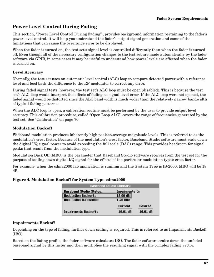
Modulation Back Off (MBO) is the parameter that Baseband Studio software receives from the test set for the purpose of scaling down digital I/Q signal for the effects of the particular modulation type’s crest factor.
For example, when the cdma2000 lab application is running and the System Type is IS-2000, MBO will be 18 dB.
Figure 4. Modulation Backoff for System Type cdma2000
Impairments Backoff
Depending on the type of fading, further down-scaling is required. This is referred to as Impairments Backoff (IBO).
Based on the fading profile, the fader software calculates IBO. The fader software scales down the unfaded baseband signal by this factor and then multiplies the resulting signal with the complex fading vector.
68
Fader System Requirements
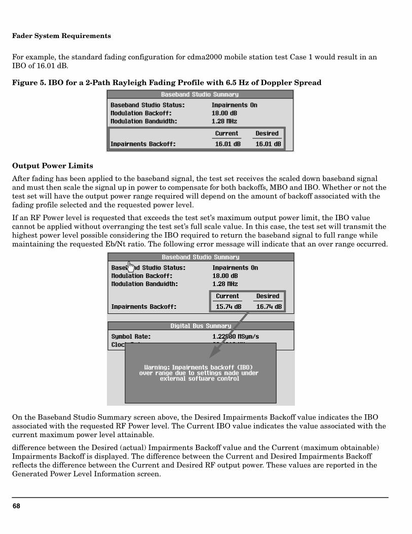
For example, the standard fading configuration for cdma2000 mobile station test Case 1 would result in an IBO of 16.01 dB.
Figure 5. IBO for a 2-Path Rayleigh Fading Profile with 6.5 Hz of Doppler Spread
Output Power Limits
After fading has been applied to the baseband signal, the test set receives the scaled down baseband signal and must then scale the signal up in power to compensate for both backoffs, MBO and IBO. Whether or not the test set will have the output power range required will depend on the amount of backoff associated with the fading profile selected and the requested power level.
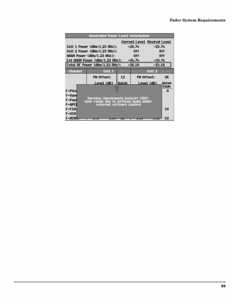
If an RF Power level is requested that exceeds the test set’s maximum output power limit, the IBO value cannot be applied without overranging the test set’s full scale value. In this case, the test set will transmit the highest power level possible considering the IBO required to return the baseband signal to full range while maintaining the requested Eb/Nt ratio. The following error message will indicate that an over range occurred.
On the Baseband Studio Summary screen above, the Desired Impairments Backoff value indicates the IBO associated with the requested RF Power level. The Current IBO value indicates the value associated with the current maximum power level attainable.
difference between the Desired (actual) Impairments Backoff value and the Current (maximum obtainable) Impairments Backoff is displayed. The difference between the Current and Desired Impairments Backoff reflects the difference between the Current and Desired RF output power. These values are reported in the Generated Power Level Information screen.
69
Fader System Requirements
70
Fader System Requirements
Calibration
ALC Open Loop Calibration
In addition to the same calibrations required for non-fader operation, there is one additional calibration routine required for accurate faded signals. It is called ALC Open Loop Calibration.
When the fader is on, the test set’s ALC (Automatic Level Control) loop is disabled. The ALC loop normally measures output power, continually applying correction values to the output level through a feedback loop. If allowed to operate in the closed loop mode, level changes introduced by signal fading would essentially be canceled out.
The method used to obtain calibrated output levels on faded signals is called “Open Loop ALC”. In this mode, the ALC path is opened and corrections applied to the output signal level are obtained from calibration tables in the test set’s memory. These tables are built during the ALC Open Loop Calibration. ALC open loop calibration values provide level correction across the complete frequency range of the test set.
The Open Loop ALC calibration routine must be run initially before performing faded tests. The test set should be allowed to warm up at least a two hours for the internal temperatures to stabilize. After the initial calibration, Open Loop ALC should be run about every six months or when the test set’s internal temperature changes more the +/- 5 degrees C from the temperature during the last calibration. A temperature sensor inside the test set detects when +/- 5 degrees C of temperature drift has occurred and displays a message on the front panel.
Open Loop ALC is accessed through the Digital Bus Info field (left 3 of 4 Call Control menu). The entire process takes about two minutes. Call processing is disabled during this time.
71
Fader System Requirements
I/Q Calibration
When fading is applied to the baseband signal, signal levels can momentarily drop to levels far below the average level. This drop in signal level is referred to as a deep fade, and can result in levels that approach the minimum power level the test set is capable of generating.
The test set’s lower power limit is determined by carrier leakage and residual broadband noise. Residual noise is always present, but carrier leakage caused by DC offsets in the analog baseband I/Q circuitry can be calibrated out by running the IQ calibration routine. This will ensure that the range of power levels generated by the test set extends to the lowest possible levels.
I/Q calibration, like Open Loop ALC, should be performed initially after the test set is fully warmed up and again if the operating temperature has drifted more than 5 degrees C since the last I/Q calibration.
The Cal. first IQ Modulator procedure is accessed through the System Config, Service field (right 2 of 2 Utilities menu). This calibration process takes about 10 minutes. Call processing is disabled while the calibration is in progress
NOTE Performing Cal. second IQ Modulator is not necessary for faded signals. It applies to the test set’s second RF source which is not faded.
72
Fader System Requirements
73
Fader System Requirements
The Digital Bus Connection
The digital bus carries digital baseband signals between the N5101A PCI card installed in the PC and the test set’s rear panel digital bus interface.
Digital Bus path control in the test set
A test set equipped with Option 504 includes a rear panel with an 80-pin connector labeled Digital Bus and a BBIO (Baseband Input/Output) circuit board that provides the necessary baseband I/Q signal path switching.
The correct path switching mode is automatically set by the fader software when fading is turned on or off. In addition to the path switching modes used for faded and non-faded operation, there are two path switching modes that are provided for diagnostic purposes. Before changing any Digital Bus Path settings, see “Critical Fading Solution Settings” on page 65.
The Digital Bus Path menu consists of the following settings:
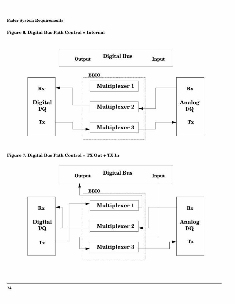
• Internal - For normal non-faded operation. Routes the test set’s digital I/Q signal to the analog I/Q circuitry. See Figure 6. “Digital Bus Path Control = Internal”.
• TX Out + TX In - For normal faded operation. Sends digital I/Q data from the test set to a PC via the Digital Bus output and routes the Digital Bus data input from a PC to the test set’s analog I/Q circuitry. See Figure 7. “Digital Bus Path Control = TX Out + TX In”.
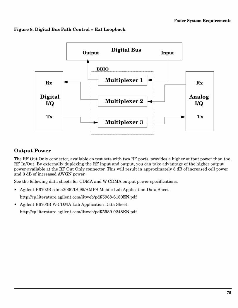
• Diag Loopback - Used for testing path switching internal to the test set. Transmitted digital I/Q data bits are routed back to the digital I/Q receiver. No data is sent to/from the Digital Bus.
• Ext Loopback - Used for testing external (N5101A PCI card) hardware. Routes the data input from the PC to the Digital Bus back to the PC via the Digital bus output. This is used when the “Run Self Tests for Selected Item button is selected from the System Configuration window (see “Configuring the Fader System” on page 13).
• TX Output Only - Reserved for future use.
• TX Out + I Data - Reserved for future use.
• TX Out + Q Data - Reserved for future use.
74
Fader System Requirements
Figure 6. Digital Bus Path Control = Internal
Figure 7. Digital Bus Path Control = TX Out + TX In
Digital BusOutput Input
Multiplexer 1
DigitalI/Q
Rx
Tx
Rx
Tx
AnalogI/QMultiplexer 2
Multiplexer 3
BBIO
Digital BusOutput Input
Multiplexer 1
DigitalI/Q
Rx
Tx
Rx
Tx
AnalogI/QMultiplexer 2
Multiplexer 3
BBIO
75
Fader System Requirements
Figure 8. Digital Bus Path Control = Ext Loopback
Output Power
The RF Out Only connector, available on test sets with two RF ports, provides a higher output power than the RF In/Out. By externally duplexing the RF input and output, you can take advantage of the higher output power available at the RF Out Only connector. This will result in approximately 8 dB of increased cell power and 3 dB of increased AWGN power.
See the following data sheets for CDMA and W-CDMA output power specifications:
• Agilent E6702B cdma2000/IS-95/AMPS Mobile Lab Application Data Sheet
http://cp.literature.agilent.com/litweb/pdf/5988-6180EN.pdf
• Agilent E6703B W-CDMA Lab Application Data Sheet
http://cp.literature.agilent.com/litweb/pdf/5989-0248EN.pdf
Digital BusOutput Input
Multiplexer 1
DigitalI/Q
Rx
Tx
Rx
Tx
AnalogI/QMultiplexer 2
Multiplexer 3
BBIO
76
Fader System Requirements
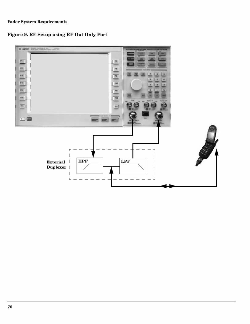
Figure 9. RF Setup using RF Out Only Port
HPF LPFExternalDuplexer
77
Fader System Requirements
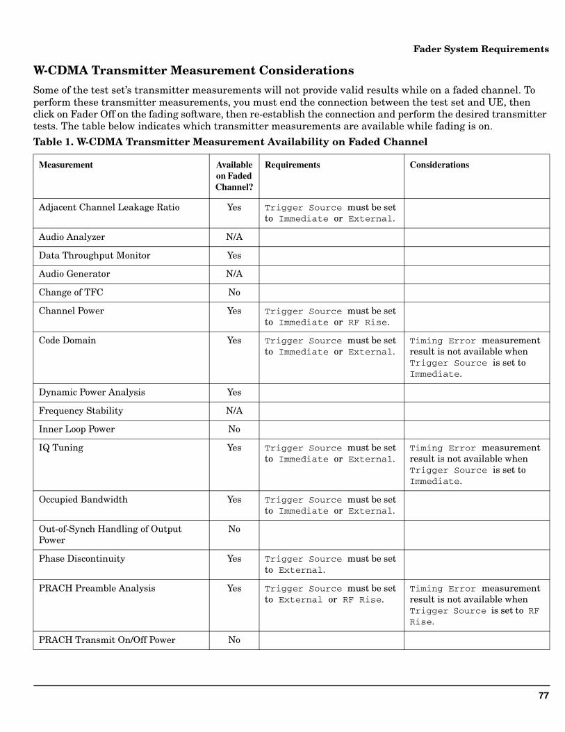
W-CDMA Transmitter Measurement Considerations
Some of the test set’s transmitter measurements will not provide valid results while on a faded channel. To perform these transmitter measurements, you must end the connection between the test set and UE, then click on Fader Off on the fading software, then re-establish the connection and perform the desired transmitter tests. The table below indicates which transmitter measurements are available while fading is on.
Table 1. W-CDMA Transmitter Measurement Availability on Faded Channel
Measurement Available on Faded Channel?
Requirements Considerations
Adjacent Channel Leakage Ratio Yes Trigger Source must be set to Immediate or External.
Audio Analyzer N/A
Data Throughput Monitor Yes
Audio Generator N/A
Change of TFC No
Channel Power Yes Trigger Source must be set to Immediate or RF Rise.
Code Domain Yes Trigger Source must be set to Immediate or External.
Timing Error measurement result is not available when Trigger Source is set to Immediate.
Dynamic Power Analysis Yes
Frequency Stability N/A
Inner Loop Power No
IQ Tuning Yes Trigger Source must be set to Immediate or External.
Timing Error measurement result is not available when Trigger Source is set to Immediate.
Occupied Bandwidth Yes Trigger Source must be set to Immediate or External.
Out-of-Synch Handling of Output Power
No
Phase Discontinuity Yes Trigger Source must be set to External.
PRACH Preamble Analysis Yes Trigger Source must be set to External or RF Rise.
Timing Error measurement result is not available when Trigger Source is set to RF Rise.
PRACH Transmit On/Off Power No
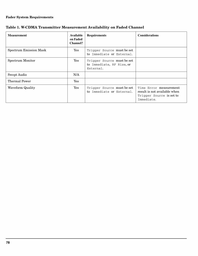
78
Fader System Requirements
Spectrum Emission Mask Yes Trigger Source must be set to Immediate or External.
Spectrum Monitor Yes Trigger Source must be set to Immediate, RF Rise, or External.
Swept Audio N/A
Thermal Power Yes
Waveform Quality Yes Trigger Source must be set to Immediate or External.
Time Error measurement result is not available when Trigger Source is set to Immediate.
Table 1. W-CDMA Transmitter Measurement Availability on Faded Channel
Measurement Available on Faded Channel?
Requirements Considerations
79
Fader System Requirements
Position Location
The E5515C with option E5515CU - 504 installed for the fader is not compatible with the R1431A and E5515C H16 gpsOne calibration.
If the E5515C has been calibrated for gpsOne with either:
• Local service center R1431A or
• a new purchase with E5515C option H16
the calibration data uncertainty will be degraded from +/-17 nS to +/-30 nS.
The gpsOne testing itself is not effected by fader options. Only the certainty of the gpsOne data is degraded. If the uncertainties are determined by the user to be acceptable, gpsOne testing can still be valid. Agilent, however, will not specify or support gpsOne operation on instruments that have E5515CU option 504 installed.
R1431 re-calibration of the E5515C with E5515CU option 504 is not supported.
80
Fader System Requirements
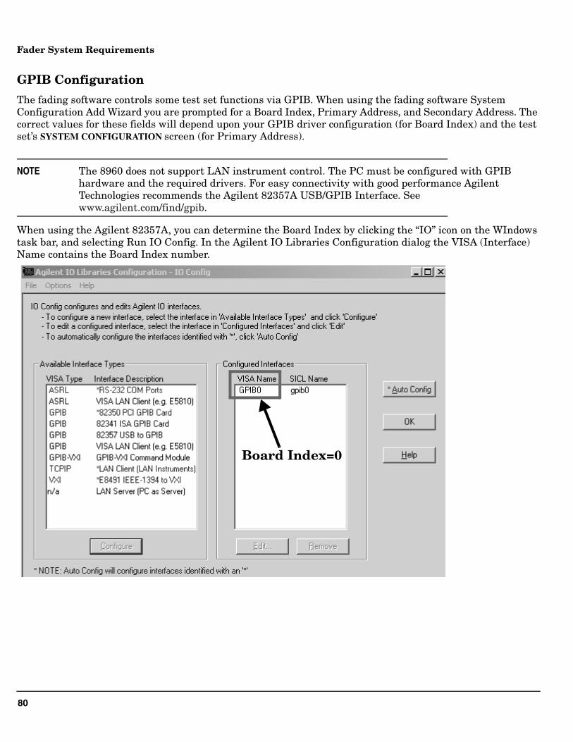
GPIB Configuration
The fading software controls some test set functions via GPIB. When using the fading software System Configuration Add Wizard you are prompted for a Board Index, Primary Address, and Secondary Address. The correct values for these fields will depend upon your GPIB driver configuration (for Board Index) and the test set’s SYSTEM CONFIGURATION screen (for Primary Address).
NOTE The 8960 does not support LAN instrument control. The PC must be configured with GPIB hardware and the required drivers. For easy connectivity with good performance Agilent Technologies recommends the Agilent 82357A USB/GPIB Interface. See www.agilent.com/find/gpib.
When using the Agilent 82357A, you can determine the Board Index by clicking the “IO” icon on the WIndows task bar, and selecting Run IO Config. In the Agilent IO Libraries Configuration dialog the VISA (Interface) Name contains the Board Index number.
Board Index=0
81
Troubleshooting
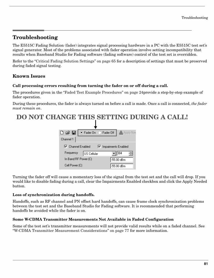
Troubleshooting The E5515C Fading Solution (fader) integrates signal processing hardware in a PC with the E5515C test set’s signal generator. Most of the problems associated with fader operation involve setting incompatibility that results when Baseband Studio for Fading software (fading software) control of the test set is overridden.
Refer to the “Critical Fading Solution Settings” on page 65 for a description of settings that must be preserved during faded signal testing.
Known Issues
Call processing errors resulting from turning the fader on or off during a call.
The procedures given in the “Faded Test Example Procedures” on page 24provide a step-by-step example of fader operation.
During these procedures, the fader is always turned on before a call is made. Once a call is connected, the fader must remain on.
Turning the fader off will cause a momentary loss of the signal from the test set and the call will drop. If you would like to disable fading during a call, clear the Impairments Enabled checkbox and click the Apply Needed button.
Loss of synchronization during handoffs.
Handoffs, such as RF channel and PN offset hard handoffs, can cause frame clock synchronization problems between the test set and the Baseband Studio for Fading software. It is recommended that performing handoffs be avoided while the fader is on.
Some W-CDMA Transmitter Measurements Not Available in Faded Configuration
Some of the test set’s transmitter measurements will not provide valid results while on a faded channel. See “W-CDMA Transmitter Measurement Considerations” on page 77 for more information.
DO NOT CHANGE THIS SETTING DURING A CALL!
82
Troubleshooting
Other Considerations
• It is recommended that you perform call processing operations (such as establishing a call and changing RMCs) without channel impairments, to ensure that the UE is able to receive and properly decode the signaling from the test set.
Error Messages
The following test set error messages can occur during fader operation:
NOTE Refer to the online Help for fading software error messages that appear on the PC.
Checking Fader Hardware Connectivity
There are several diagnostic routines that can be run to check fader system connectivity.
The diagnostic routines and conditions for running them are listed in Table 3.:
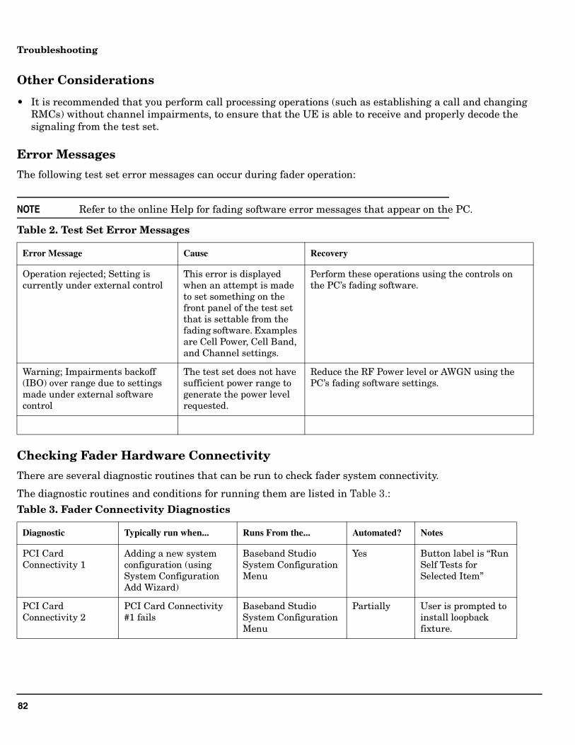
Table 2. Test Set Error Messages
Error Message Cause Recovery
Operation rejected; Setting is currently under external control
This error is displayed when an attempt is made to set something on the front panel of the test set that is settable from the fading software. Examples are Cell Power, Cell Band, and Channel settings.
Perform these operations using the controls on the PC’s fading software.
Warning; Impairments backoff (IBO) over range due to settings made under external software control
The test set does not have sufficient power range to generate the power level requested.
Reduce the RF Power level or AWGN using the PC’s fading software settings.
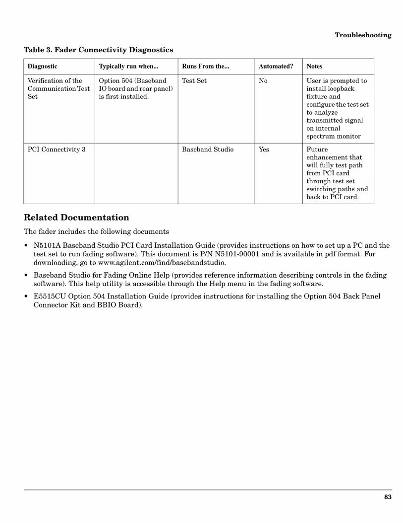
Table 3. Fader Connectivity Diagnostics
Diagnostic Typically run when... Runs From the... Automated? Notes
PCI Card Connectivity 1
Adding a new system configuration (using System Configuration Add Wizard)
Baseband Studio System Configuration Menu
Yes Button label is “Run Self Tests for Selected Item”
PCI Card Connectivity 2
PCI Card Connectivity #1 fails
Baseband Studio System Configuration Menu
Partially User is prompted to install loopback fixture.
83
Troubleshooting
Related Documentation
The fader includes the following documents
• N5101A Baseband Studio PCI Card Installation Guide (provides instructions on how to set up a PC and the test set to run fading software). This document is P/N N5101-90001 and is available in pdf format. For downloading, go to www.agilent.com/find/basebandstudio.
• Baseband Studio for Fading Online Help (provides reference information describing controls in the fading software). This help utility is accessible through the Help menu in the fading software.
• E5515CU Option 504 Installation Guide (provides instructions for installing the Option 504 Back Panel Connector Kit and BBIO Board).
Verification of the Communication Test Set
Option 504 (Baseband IO board and rear panel) is first installed.
Test Set No User is prompted to install loopback fixture and configure the test set to analyze transmitted signal on internal spectrum monitor
PCI Connectivity 3 Baseband Studio Yes Future enhancement that will fully test path from PCI card through test set switching paths and back to PCI card.
Table 3. Fader Connectivity Diagnostics
Diagnostic Typically run when... Runs From the... Automated? Notes