Embed Size (px)
Citation preview
MV electrical network management
Easergy range
T200 I & E MV substation control unit
User’s manual
Easergy T200 I Contents
2 NT00114-EN-05
T200T200T200T200 I I I I & E & E & E & E .......................................................................................................................................................... 1
1 GENERAL DESCRIPTION................................ ......................................................................................... 3
1.1 FUNCTIONAL DESCRIPTION ........................................................................................................................... 3 1.2 DESCRIPTION OF EQUIPMENT........................................................................................................................ 5 1.3 T200 I & E BLOCK DIAGRAM ......................................................................................................................... 6
2 CONNECTION TO THE T200 .................................................................................................................... 8
2.1 STEP 1 - INSTALLING JAVA RUNTIME ENVIRONMENT 5.0................................................................................. 9 2.2 STEP 2 - INSTALLING THE USB DRIVER ....................................................................................................... 10 2.3 STEP 3 - CREATION OF THE USB LOCAL AREA NETWORK CONNECTION ......................................................... 11 2.4 STEP 4 – CREATION OF THE PSTN OR GSM REMOTE NETWORK CONNECTION.............................................. 12 2.5 STEP 5 – STARTING CONNECTION WITH THE T200 ....................................................................................... 13 2.6 OVERVIEW OF THE EMBEDDED WEB SERVER OF THE T200........................................................................... 16
3 T200 CONFIGURATION .......................................................................................................................... 21
3.1 24V/48V AUXILIARY POWER SUPPLY (OPTION)............................................................................................. 22 3.2 CONFIGURATION OF SYNCHRONIZATION BY GPS ......................................................................................... 23 3.3 CONFIGURATION OF SNTP SERVICE ........................................................................................................... 26 3.4 CONFIGURATION OF ETHERNET INTERFACES ............................................................................................... 27 3.5 SAVE/RESTORE CONFIGURATION PARAMETERS ........................................................................................... 28 3.6 DUMMY CONTROL OPTION .......................................................................................................................... 29 3.7 PARAMETERS FOR COMMUNICATION WITH THE SUPERVISOR ......................................................................... 30 3.8 SWITCH CONTROL PARAMETERS ................................................................................................................. 46 3.9 PARAMETERS OF THE VARIOUS OPTIONS ..................................................................................................... 49 3.10 AUTOMATIC CONTROL PARAMETERS ....................................................................................................... 51 3.11 PARAMETERS OF THE FAULT DETECTION MODULE.................................................................................... 56 3.12 CUSTOMIZATION OF T200 VARIABLES..................................................................................................... 59 3.13 CUSTOMIZATION OF T200 CLASSES........................................................................................................ 72 3.14 TESTS AT COMMISSIONING ..................................................................................................................... 73
4 OPERATION ............................................................................................................................................ 74
4.1 OPERATING MODE...................................................................................................................................... 74 4.2 ACCESSIBILITY ........................................................................................................................................... 75
5 MAINTENANCE ........................................ ............................................................................................... 76
5.1 DIAGNOSTICS VIA THE FRONT PANEL INDICATOR LAMPS AND LOGS ................................................................ 77 5.2 POWER SUPPLIES ...................................................................................................................................... 80 5.3 CARD REPLACEMENT.................................................................................................................................. 81 5.4 CPU CARD SOFTWARE CONFIGURATION ...................................................................................................... 82
6 APPENDIX A - CONFIGURABLE PARAMETERS ............... .................................................................. 84
7 APPENDIX B - GENERAL CHARACTERISTICS ............... .................................................................... 92
Overview General description
NT00114-EN-05 3
1 General description
1.1 Functional description Easergy T200 I and T200 E is designed to be installed in MV/LV network substations. It contains all the functions required to monitor and control the motorized cubicles:
Management of MV switch opening/closing electric co ntrol unit The control is triggered by REMOTE CONTROL from the remote control station or by a LOCAL operator command (pushbutton) or by internal AUTOMATIC CONTROLS. Phase-to-phase or phase-to-earth fault current detection . Measurement acquisition and processing: When the fault detection option is installed on the equipment, the T200 I and E incorporates for each channel one of the following measurements: � Calculation of the rms load current (if current measurement module installed); � Single-phase or three-phase voltage measurement (if voltage measurement
module installed). Monitoring, for the purposes of remote indication a nd/or local display, of MV substation and T200 I and E information: � Open/closed position of MV switches; � "Locked" state of MV switches; � Detection of the flow of phase-to-phase or phase-to-earth fault current (on
channels provided with the fault detection option); � Voltage presence (if the option is present); � Automatic control ON/OFF position; � Immediate alternating supply undervoltage; � Time-delayed alternating supply undervoltage; � Charger fault; � Battery fault; � External 12 V power supply failure; � Motorization supply undervoltage. Dated logging events: Time-stamped chronological logging of events and measurements. This information can be transmitted to the control centre and archived in logs for consultation and local downloading (in the form of files), by connection of a microcomputer. Automatic controls: � SEC (Sectionalizer): Automatic control for opening the MV switch following
detection of a number of fault currents in the source substation reset cycle. � ATS (Automatic Transfer of Source): Automatic source changeover upon voltage
loss detected on one of the channels. � BTA (Bus Tie Automatism) : Automatic control for source changeover between 2
incoming switches and one busbar coupling switch. Backed-up power supply For all the control unit components, the transmission equipment and the switch motorization with several hours' power reserve in the event of an AC supply outage. Local communication or communication with the remot e control centre � One or two communication ports (option) are available for remote communication
with the control centre so as to manage two transmission channels. These ports can be used redundantly (normal/backup), for repeater or maintenance applications. The ports use either modems integrated in the COM card or external equipment managed by the rack serial link.
� A choice of modem for each port allowing any type of mounting: ♦ Radio (600/1200 baud FSK or 1200/2400 FFSK) ♦ PSTN isolated at 8 kV (300 to 14400 bits/s - V32 bis) ♦ GSM / GPRS (European dual-band version 900 MHz – 1800 MHz, US dual-
band version 850 MHz – 1900 MHz), SIM card accessible on the front panel ♦ LL isolated at 8 kV (1200 baud FSK) ♦ RS232 ♦ RS485 isolated at 2 kV (19200 baud)
Note: In an RS232 link, port 1 is replaced by the RS232 port integral with the COM card and accessible via the 9-pin D-SUB (DB-9) connector on the right of the rack.
Overview General description
4 NT00114-EN-05
� A catalogue of communication protocols for communication with the control centre,
changing constantly: ♦ IEC 870-5-101 ♦ IEC 870-5-104 ♦ DNP3, DNP3 / IP ♦ Modbus, Modbus / IP ♦ Other proprietary protocols (PID1, PUR2.2, PUR2.4, EDP, etc.).
� An Ethernet communication port is available for communication with the control centre or for access from the local PC for consultation/configuration (Modbus IP protocol, IEC 870-5-104, DNP3 IP). This port is accessible on the front of the COM card.
� A USB communication port is available for communication with the local PC for consultation/configuration. This port is accessible on the front of the COM card.
Communication with local equipment (option) A Modbus RS485 communication port (2 wires - isolated at 2 kV) is available (on option) for dialogue with equipment communicating with the T200 (e.g. Sepam, etc.). Time synchronization of the equipment Time setting for event dating can be performed: � by the laptop PC for consultation/configuration of the T200 (manually or
automatically via the PC time); � by the control centre (if the protocol permits); � by GPS sync (option). The minimum precision of time setting is in this case
approximately 50 ms; � by SNTP sync (option) from an Ethernet network. The precision of time setting is
in this case approximately one second.
Overview General description
NT00114-EN-05 5
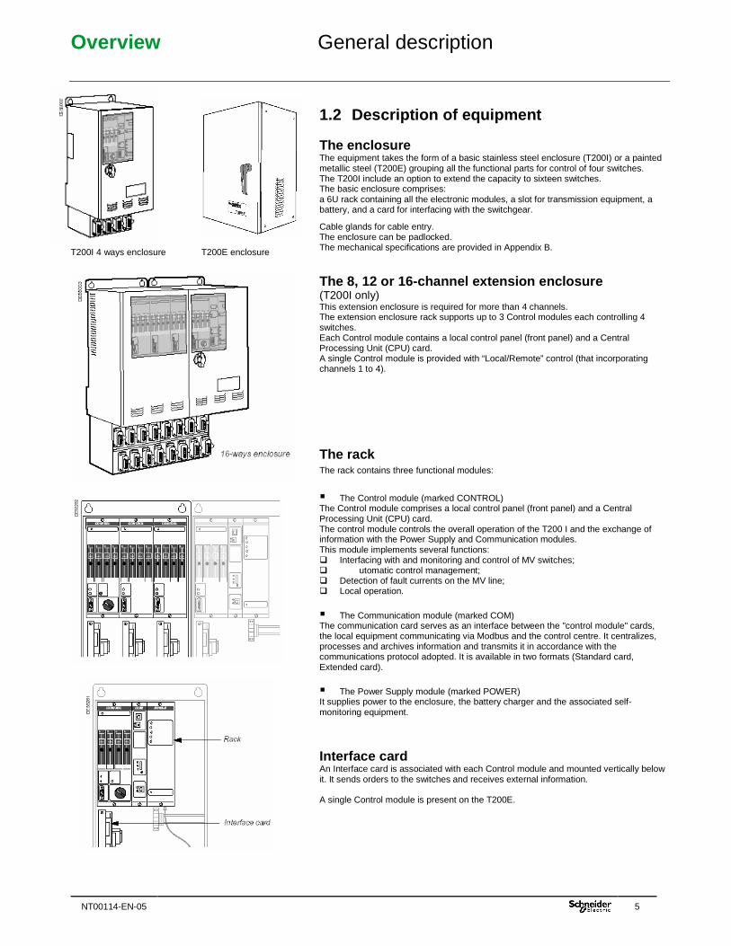
T200I 4 ways enclosure T200E enclosure
1.2 Description of equipment
The enclosure The equipment takes the form of a basic stainless steel enclosure (T200I) or a painted metallic steel (T200E) grouping all the functional parts for control of four switches. The T200I include an option to extend the capacity to sixteen switches. The basic enclosure comprises: a 6U rack containing all the electronic modules, a slot for transmission equipment, a battery, and a card for interfacing with the switchgear.
Cable glands for cable entry. The enclosure can be padlocked. The mechanical specifications are provided in Appendix B.
The 8, 12 or 16-channel extension enclosure (T200I only) This extension enclosure is required for more than 4 channels. The extension enclosure rack supports up to 3 Control modules each controlling 4 switches. Each Control module contains a local control panel (front panel) and a Central Processing Unit (CPU) card. A single Control module is provided with “Local/Remote” control (that incorporating channels 1 to 4).
The rack The rack contains three functional modules:
� The Control module (marked CONTROL) The Control module comprises a local control panel (front panel) and a Central Processing Unit (CPU) card. The control module controls the overall operation of the T200 I and the exchange of information with the Power Supply and Communication modules. This module implements several functions: � Interfacing with and monitoring and control of MV switches; � utomatic control management; � Detection of fault currents on the MV line; � Local operation.
� The Communication module (marked COM) The communication card serves as an interface between the "control module" cards, the local equipment communicating via Modbus and the control centre. It centralizes, processes and archives information and transmits it in accordance with the communications protocol adopted. It is available in two formats (Standard card, Extended card).
� The Power Supply module (marked POWER) It supplies power to the enclosure, the battery charger and the associated self-monitoring equipment.
Interface card An Interface card is associated with each Control module and mounted vertically below it. It sends orders to the switches and receives external information. A single Control module is present on the T200E.
Overview General description
6 NT00114-EN-05
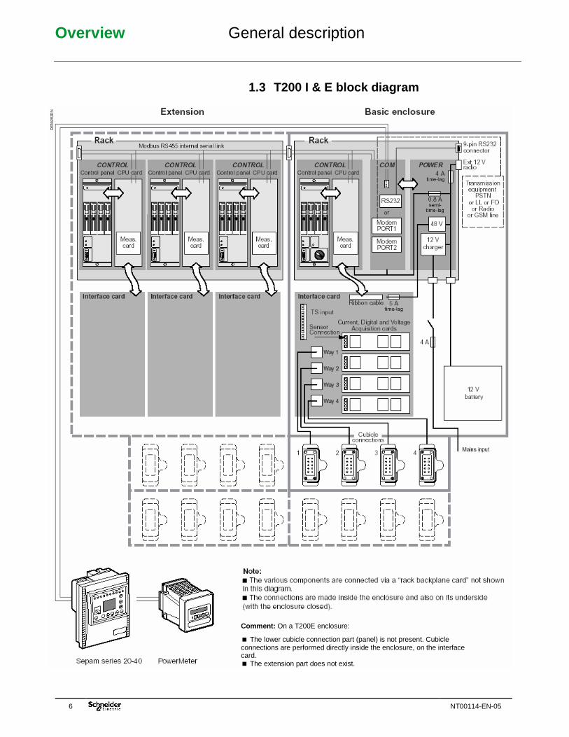
1.3 T200 I & E block diagram
Comment: On a T200E enclosure:
� The lower cubicle connection part (panel) is not present. Cubicle connections are performed directly inside the enclosure, on the interface card. � The extension part does not exist.
Installation Installing the enclosure
NT00114-EN-05 7
Refer to the T200I installation manual supplied with the equipment to obtain information concerning installation of the T200I enclosure: "NT00032-FR-EN-ES-xx". Refer to the T200I installation manual supplied with the equipment to obtain information concerning installation of the T200E enclosure: "NT00224-FR-EN-xx".
Connection to the T200 Initialization of connection
8 NT00114-EN-05
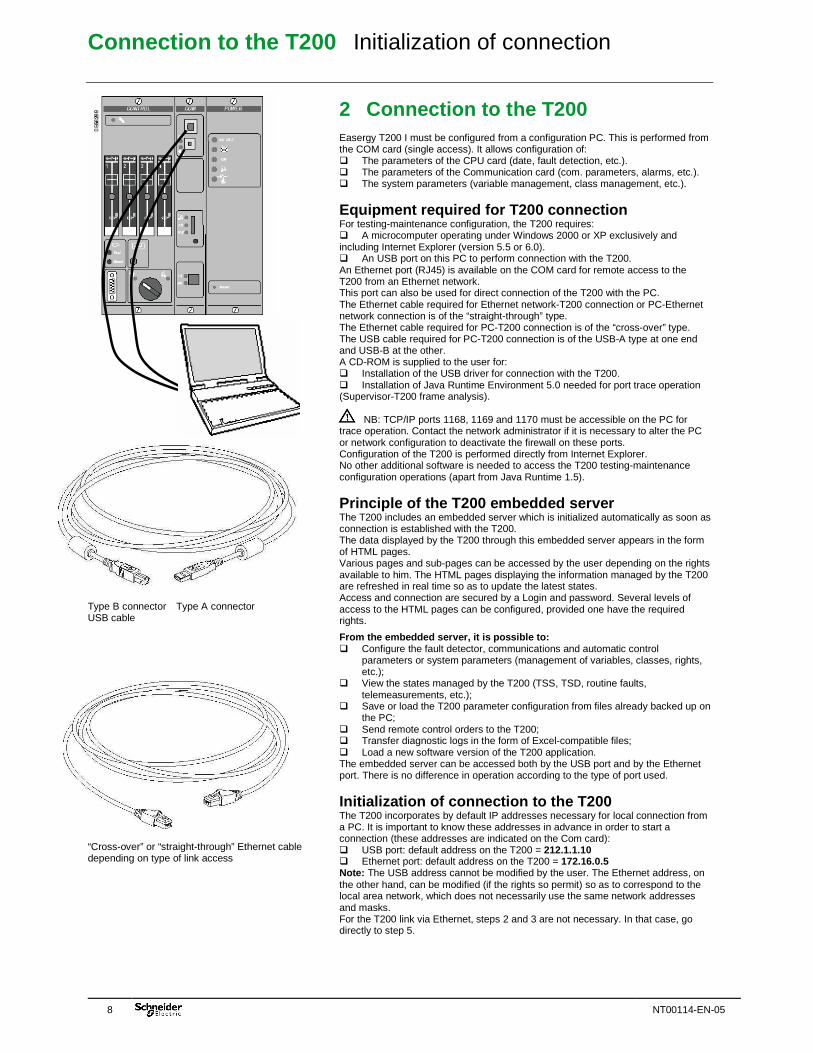
Type B connector Type A connector USB cable
“Cross-over” or “straight-through” Ethernet cable depending on type of link access
2 Connection to the T200 Easergy T200 I must be configured from a configuration PC. This is performed from the COM card (single access). It allows configuration of: � The parameters of the CPU card (date, fault detection, etc.). � The parameters of the Communication card (com. parameters, alarms, etc.). � The system parameters (variable management, class management, etc.).
Equipment required for T200 connection For testing-maintenance configuration, the T200 requires: � A microcomputer operating under Windows 2000 or XP exclusively and including Internet Explorer (version 5.5 or 6.0). � An USB port on this PC to perform connection with the T200. An Ethernet port (RJ45) is available on the COM card for remote access to the T200 from an Ethernet network. This port can also be used for direct connection of the T200 with the PC. The Ethernet cable required for Ethernet network-T200 connection or PC-Ethernet network connection is of the “straight-through” type. The Ethernet cable required for PC-T200 connection is of the “cross-over” type. The USB cable required for PC-T200 connection is of the USB-A type at one end and USB-B at the other. A CD-ROM is supplied to the user for: � Installation of the USB driver for connection with the T200. � Installation of Java Runtime Environment 5.0 needed for port trace operation (Supervisor-T200 frame analysis). NB: TCP/IP ports 1168, 1169 and 1170 must be accessible on the PC for trace operation. Contact the network administrator if it is necessary to alter the PC or network configuration to deactivate the firewall on these ports. Configuration of the T200 is performed directly from Internet Explorer. No other additional software is needed to access the T200 testing-maintenance configuration operations (apart from Java Runtime 1.5).
Principle of the T200 embedded server The T200 includes an embedded server which is initialized automatically as soon as connection is established with the T200. The data displayed by the T200 through this embedded server appears in the form of HTML pages. Various pages and sub-pages can be accessed by the user depending on the rights available to him. The HTML pages displaying the information managed by the T200 are refreshed in real time so as to update the latest states. Access and connection are secured by a Login and password. Several levels of access to the HTML pages can be configured, provided one have the required rights.
From the embedded server, it is possible to: � Configure the fault detector, communications and automatic control
parameters or system parameters (management of variables, classes, rights, etc.);
� View the states managed by the T200 (TSS, TSD, routine faults, telemeasurements, etc.);
� Save or load the T200 parameter configuration from files already backed up on the PC;
� Send remote control orders to the T200; � Transfer diagnostic logs in the form of Excel-compatible files; � Load a new software version of the T200 application. The embedded server can be accessed both by the USB port and by the Ethernet port. There is no difference in operation according to the type of port used.
Initialization of connection to the T200 The T200 incorporates by default IP addresses necessary for local connection from a PC. It is important to know these addresses in advance in order to start a connection (these addresses are indicated on the Com card): � USB port: default address on the T200 = 212.1.1.10 � Ethernet port: default address on the T200 = 172.16.0.5 Note: The USB address cannot be modified by the user. The Ethernet address, on the other hand, can be modified (if the rights so permit) so as to correspond to the local area network, which does not necessarily use the same network addresses and masks. For the T200 link via Ethernet, steps 2 and 3 are not necessary. In that case, go directly to step 5.
Connection to the T200 Initialization of connection
NT00114-EN-05 9
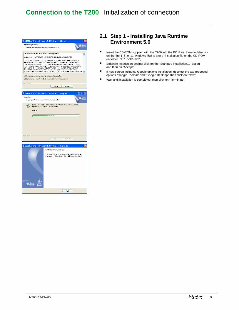
2.1 Step 1 - Installing Java Runtime Environment 5.0
� Insert the CD-ROM supplied with the T200 into the PC drive, then double-click on the “jre-1_5_0_11-windows-i586-p-s.exe” installation file on the CD-ROM (in folder : "D:\Tools\Java").
� Software installation begins; click on the “Standard installation…" option and then on “Accept”.
� If new screen including Google options installation, deselect the two proposed options "Google Toolbar" and "Google Desktop", then click on "Next".
� Wait until installation is completed, then click on “Terminate”.
Connection to the T200 Initialization of connection
10 NT00114-EN-05
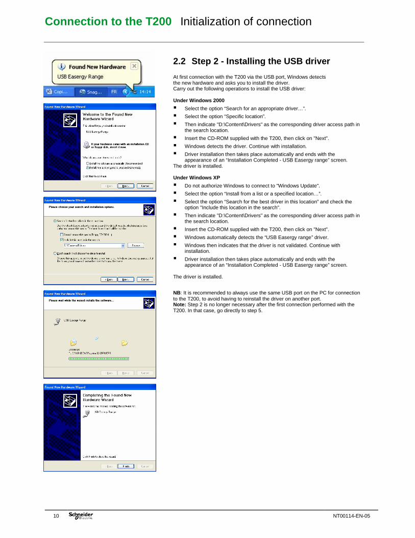
2.2 Step 2 - Installing the USB driver At first connection with the T200 via the USB port, Windows detects the new hardware and asks you to install the driver. Carry out the following operations to install the USB driver: Under Windows 2000
� Select the option “Search for an appropriate driver…”.
� Select the option “Specific location”.
� Then indicate "D:\Content\Drivers" as the corresponding driver access path in the search location.
� Insert the CD-ROM supplied with the T200, then click on "Next".
� Windows detects the driver. Continue with installation.
� Driver installation then takes place automatically and ends with the appearance of an “Installation Completed - USB Easergy range” screen.
The driver is installed. Under Windows XP
� Do not authorize Windows to connect to "Windows Update".
� Select the option “Install from a list or a specified location…”.
� Select the option “Search for the best driver in this location” and check the option "Include this location in the search".
� Then indicate "D:\Content\Drivers" as the corresponding driver access path in the search location.
� Insert the CD-ROM supplied with the T200, then click on "Next".
� Windows automatically detects the “USB Easergy range” driver.
� Windows then indicates that the driver is not validated. Continue with installation.
� Driver installation then takes place automatically and ends with the appearance of an “Installation Completed - USB Easergy range” screen.
The driver is installed.
NB: It is recommended to always use the same USB port on the PC for connection to the T200, to avoid having to reinstall the driver on another port. Note: Step 2 is no longer necessary after the first connection performed with the T200. In that case, go directly to step 5.
Connection to the T200 Initialization of connection
NT00114-EN-05 11
2.3 Step 3 - Creation of the USB local area network connection
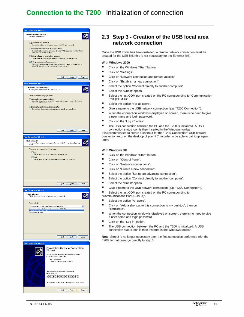
Once the USB driver has been installed, a remote network connection must be created for the USB link (this is not necessary for the Ethernet link). With Windows 2000
� Click on the Windows “Start” button.
� Click on “Settings”.
� Click on “Network connection and remote access”.
� Click on “Establish a new connection”.
� Select the option “Connect directly to another computer”.
� Select the “Guest” option.
� Select the last COM port created on the PC corresponding to “Communication Port (COM X)”.
� Select the option “For all users”.
� Give a name to the USB network connection (e.g. “T200 Connection”).
� When the connection window is displayed on screen, there is no need to give a user name and login password.
� Click on the “Log in” option.
� The USB connection between the PC and the T200 is initialized. A USB connection status icon is then inserted in the Windows toolbar.
It is recommended to create a shortcut for the “T200 Connection” USB network connection (e.g. on the desktop of your PC, in order to be able to call it up again later). With Windows XP
� Click on the Windows “Start” button.
� Click on “Control Panel”.
� Click on “Network connections”.
� Click on “Create a new connection”.
� Select the option “Set up an advanced connection”.
� Select the option “Connect directly to another computer”.
� Select the “Guest” option.
� Give a name to the USB network connection (e.g. “T200 Connection”).
� Select the last COM port created on the PC corresponding to “Communications Port (COM X)”.
� Select the option “All users”.
� Click on “Add a shortcut to this connection to my desktop”, then on “Terminate”.
� When the connection window is displayed on screen, there is no need to give a user name and login password.
� Click on the “Log in” option.
� The USB connection between the PC and the T200 is initialized. A USB connection status icon is then inserted in the Windows toolbar.
Note: Step 3 is no longer necessary after the first connection performed with the T200. In that case, go directly to step 5.
Connection to the T200 Initialization of connection
12 NT00114-EN-05
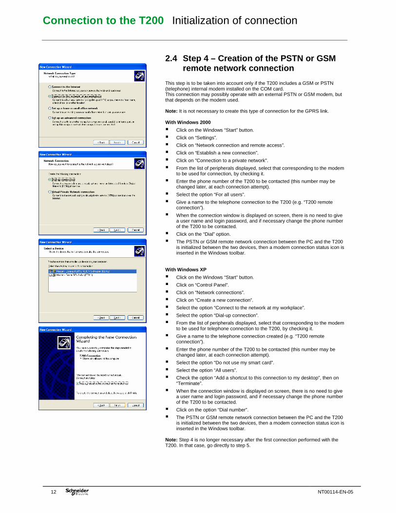
2.4 Step 4 – Creation of the PSTN or GSM remote network connection
This step is to be taken into account only if the T200 includes a GSM or PSTN (telephone) internal modem installed on the COM card. This connection may possibly operate with an external PSTN or GSM modem, but that depends on the modem used. Note: It is not necessary to create this type of connection for the GPRS link. With Windows 2000
� Click on the Windows “Start” button.
� Click on “Settings”.
� Click on “Network connection and remote access”.
� Click on “Establish a new connection”.
� Click on "Connection to a private network".
� From the list of peripherals displayed, select that corresponding to the modem to be used for connection, by checking it.
� Enter the phone number of the T200 to be contacted (this number may be changed later, at each connection attempt).
� Select the option “For all users”.
� Give a name to the telephone connection to the T200 (e.g. “T200 remote connection”).
� When the connection window is displayed on screen, there is no need to give a user name and login password, and if necessary change the phone number of the T200 to be contacted.
� Click on the “Dial” option.
� The PSTN or GSM remote network connection between the PC and the T200 is initialized between the two devices, then a modem connection status icon is inserted in the Windows toolbar.
With Windows XP
� Click on the Windows “Start” button.
� Click on “Control Panel”.
� Click on “Network connections”.
� Click on “Create a new connection”.
� Select the option “Connect to the network at my workplace”.
� Select the option “Dial-up connection”.
� From the list of peripherals displayed, select that corresponding to the modem to be used for telephone connection to the T200, by checking it.
� Give a name to the telephone connection created (e.g. “T200 remote connection”).
� Enter the phone number of the T200 to be contacted (this number may be changed later, at each connection attempt).
� Select the option “Do not use my smart card”.
� Select the option “All users”.
� Check the option “Add a shortcut to this connection to my desktop”, then on “Terminate”.
� When the connection window is displayed on screen, there is no need to give a user name and login password, and if necessary change the phone number of the T200 to be contacted.
� Click on the option “Dial number”.
� The PSTN or GSM remote network connection between the PC and the T200 is initialized between the two devices, then a modem connection status icon is inserted in the Windows toolbar.
Note: Step 4 is no longer necessary after the first connection performed with the T200. In that case, go directly to step 5.
Connection to the T200 Initialization of connection
NT00114-EN-05 13
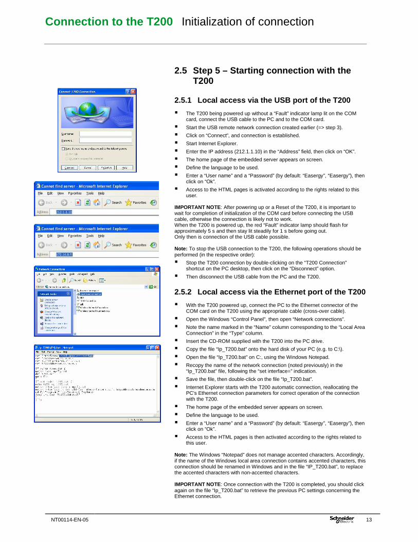
2.5 Step 5 – Starting connection with the T200
2.5.1 Local access via the USB port of the T200
� The T200 being powered up without a “Fault” indicator lamp lit on the COM card, connect the USB cable to the PC and to the COM card.
� Start the USB remote network connection created earlier (=> step 3).
� Click on “Connect”, and connection is established.
� Start Internet Explorer.
� Enter the IP address (212.1.1.10) in the “Address” field, then click on “OK”.
� The home page of the embedded server appears on screen.
� Define the language to be used.
� Enter a “User name” and a “Password” (by default: “Easergy”, “Easergy”), then click on “Ok”.
� Access to the HTML pages is activated according to the rights related to this user.
IMPORTANT NOTE: After powering up or a Reset of the T200, it is important to wait for completion of initialization of the COM card before connecting the USB cable, otherwise the connection is likely not to work. When the T200 is powered up, the red “Fault” indicator lamp should flash for approximately 5 s and then stay lit steadily for 1 s before going out. Only then is connection of the USB cable possible. Note: To stop the USB connection to the T200, the following operations should be performed (in the respective order):
� Stop the T200 connection by double-clicking on the “T200 Connection” shortcut on the PC desktop, then click on the “Disconnect” option.
� Then disconnect the USB cable from the PC and the T200.
2.5.2 Local access via the Ethernet port of the T20 0
� With the T200 powered up, connect the PC to the Ethernet connector of the COM card on the T200 using the appropriate cable (cross-over cable).
� Open the Windows “Control Panel”, then open “Network connections”.
� Note the name marked in the “Name” column corresponding to the “Local Area Connection” in the “Type” column.
� Insert the CD-ROM supplied with the T200 into the PC drive.
� Copy the file “Ip_T200.bat” onto the hard disk of your PC (e.g. to C:\).
� Open the file “Ip_T200.bat” on C:, using the Windows Notepad.
� Recopy the name of the network connection (noted previously) in the “Ip_T200.bat” file, following the “set interface=” indication.
� Save the file, then double-click on the file “Ip_T200.bat”.
� Internet Explorer starts with the T200 automatic connection, reallocating the PC's Ethernet connection parameters for correct operation of the connection with the T200.
� The home page of the embedded server appears on screen.
� Define the language to be used.
� Enter a “User name” and a “Password” (by default: “Easergy”, “Easergy”), then click on “Ok”.
� Access to the HTML pages is then activated according to the rights related to this user.
Note: The Windows “Notepad” does not manage accented characters. Accordingly, if the name of the Windows local area connection contains accented characters, this connection should be renamed in Windows and in the file “IP_T200.bat”, to replace the accented characters with non-accented characters. IMPORTANT NOTE: Once connection with the T200 is completed, you should click again on the file “Ip_T200.bat” to retrieve the previous PC settings concerning the Ethernet connection.
Connection to the T200 Initialization of connection
14 NT00114-EN-05
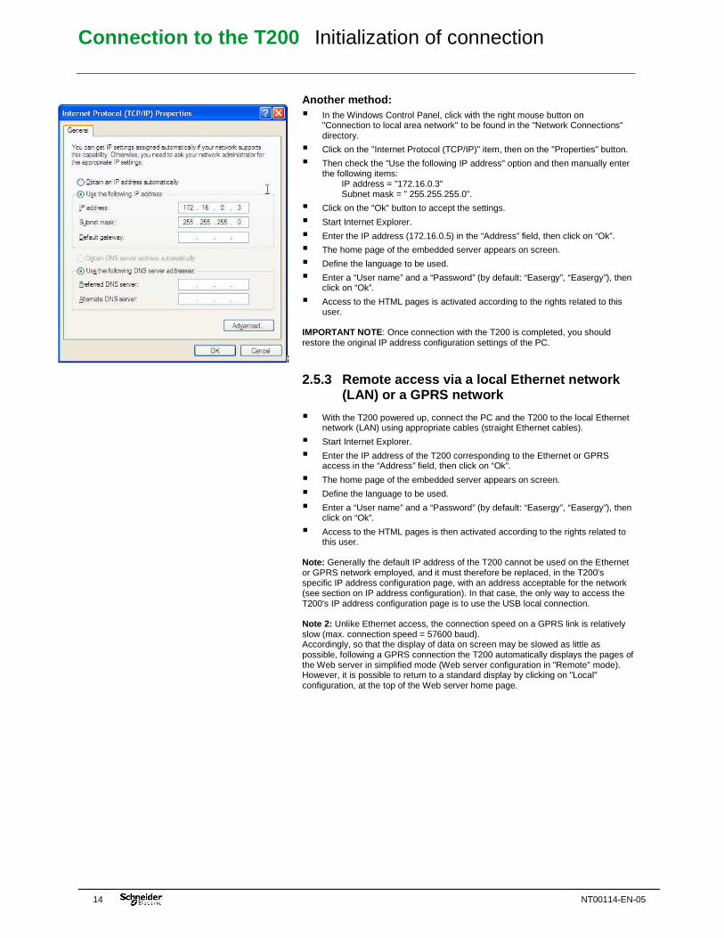
Another method: � In the Windows Control Panel, click with the right mouse button on
"Connection to local area network" to be found in the "Network Connections" directory.
� Click on the "Internet Protocol (TCP/IP)" item, then on the "Properties" button.
� Then check the "Use the following IP address" option and then manually enter the following items: IP address = "172.16.0.3" Subnet mask = " 255.255.255.0".
� Click on the "Ok" button to accept the settings.
� Start Internet Explorer.
� Enter the IP address (172.16.0.5) in the “Address” field, then click on “Ok”.
� The home page of the embedded server appears on screen.
� Define the language to be used.
� Enter a “User name” and a “Password” (by default: “Easergy”, “Easergy”), then click on “Ok”.
� Access to the HTML pages is activated according to the rights related to this user.
IMPORTANT NOTE: Once connection with the T200 is completed, you should restore the original IP address configuration settings of the PC.
2.5.3 Remote access via a local Ethernet network (LAN) or a GPRS network
� With the T200 powered up, connect the PC and the T200 to the local Ethernet network (LAN) using appropriate cables (straight Ethernet cables).
� Start Internet Explorer.
� Enter the IP address of the T200 corresponding to the Ethernet or GPRS access in the “Address” field, then click on “Ok”.
� The home page of the embedded server appears on screen.
� Define the language to be used.
� Enter a “User name” and a “Password” (by default: “Easergy”, “Easergy”), then click on “Ok”.
� Access to the HTML pages is then activated according to the rights related to this user.
Note: Generally the default IP address of the T200 cannot be used on the Ethernet or GPRS network employed, and it must therefore be replaced, in the T200's specific IP address configuration page, with an address acceptable for the network (see section on IP address configuration). In that case, the only way to access the T200's IP address configuration page is to use the USB local connection. Note 2: Unlike Ethernet access, the connection speed on a GPRS link is relatively slow (max. connection speed = 57600 baud). Accordingly, so that the display of data on screen may be slowed as little as possible, following a GPRS connection the T200 automatically displays the pages of the Web server in simplified mode (Web server configuration in "Remote" mode). However, it is possible to return to a standard display by clicking on "Local" configuration, at the top of the Web server home page.
Connection to the T200 Initialization of connection
NT00114-EN-05 15
2.5.4 Remote access via telephone or GSM link This access operates only when the T200 includes a GSM or PSTN (telephone) internal modem installed on the COM card. When an external modem is used, it is possible that this access may operate, but that depends on the modem used.
� Start the GSM-PSTN remote network connection created previously (=> step 4).
� Click on “Dial number” to start remote network connection.
� Once connection is established, start Internet Explorer.
� In the address field of Internet Explorer, enter one of the following IP addresses, depending on the port No. on which the RTC or GSM modem is installed on the T200:
- For port 1: 212.1.0.1 - For port 2: 212.1.0.3
� The home page of the embedded server then appears on screen.
� Define the language to be used.
� Enter a “User name” and a “Password” (by default: “Easergy”, “Easergy”), then click on “Ok”.
� Access to the HTML pages is activated according to the rights related to this user.
Note: Unlike a standard USB or Ethernet access, the connection speed on a telephone link is rather slow (9600 baud). Accordingly, so that the display of data on screen may be slowed as little as possible, following a PSTN or GSM connection the T200 automatically displays the pages of the Web server in simplified mode (Web server configuration in "Remote" mode). However, it is possible to return to a standard display by clicking on "Local" configuration, at the top of the Web server home page.
Connection to the T200 Overview of the Web server
16 NT00114-EN-05
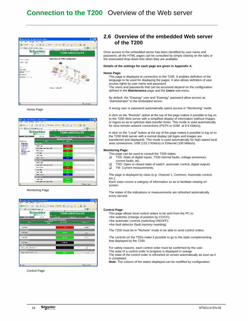
Home Page INSERER IMAGE PAGE VISUALISATION Monitoring Page Control Page
2.6 Overview of the embedded Web server of the T200
Once access to the embedded server has been identified by user name and password, all the HTML pages can be consulted by simply clicking on the tabs or the associated drop-down lists when they are available: Details of the settings for each page are given in Appendix A. Home Page:
This page is displayed at connection to the T200. It enables definition of the language to be used for displaying the pages. It also allows definition of user access rights by user name and password. The users and passwords that can be accessed depend on the configuration defined in the Maintenance page and the Users sub-menu. By default, the “Easergy” user and “Easergy” password allow access as “Administrator” to the embedded server. A wrong user or password automatically opens access in “Monitoring” mode. A click on the "Remote" option at the top of the page makes it possible to log on to the T200 Web server with a simplified display of information (without images or logos) so as to optimize data transfer times. This mode is used automatically for slow remote network connections (PSTN or GSM at 9.6 Kbits/s). A click on the "Local" button at the top of the page makes it possible to log on to the T200 Web server with a normal display (all logos and images are transferred and displayed). This mode is used automatically for high-speed local area connections: USB (115.2 Kbits/s) or Ethernet (100 Mbits/s).
Monitoring Page: This page can be used to consult the T200 states: � TSS: State of digital inputs, T200 internal faults, voltage presences,
current faults, etc. � TSD: Open or closed state of switch, automatic control, digital outputs � TM: Current measurements. The page is displayed by class (e.g. Channel 1, Common, Automatic control, etc.). Each class covers a category of information so as to facilitate viewing on screen. The states of the indications or measurements are refreshed automatically every second.
Control Page: This page allows local control orders to be sent from the PC to: • the switches (change of position by CO/CF); • the automatic controls (switching ON/OFF); • the fault detector (fault memory resetting).
The T200 must be in "Remote" mode to be able to send control orders. The controls on the TSDs make it possible to go to the state complementing that displayed by the T200. For safety reasons, each control order must be confirmed by the user. The state of a control order in progress is displayed in orange. The state of the control order is refreshed on screen automatically as soon as it is completed. Note: The colours of the states displayed can be modified by configuration.
Connection to the T200 Overview of the Web server
NT00114-EN-05 17
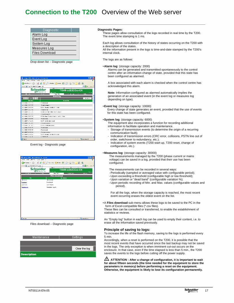
Drop-down list – Diagnostic page Event log - Diagnostic page Files download – Diagnostic page
Diagnostic Pages:
These pages allow consultation of the logs recorded in real time by the T200. The event time stamping is 1 ms. Each log allows consultation of the history of states occurring on the T200 with a description of the states. All the information present in the logs is time-and-date stamped by the T200's internal clock. The logs are as follows: • Alarm log : (storage capacity: 2000)
Alarms can be generated and transmitted spontaneously to the control centre after an information change of state, provided that this state has been configured as alarmed. A box associated with each alarm is checked when the control centre has acknowledged this alarm. Note: Information configured as alarmed automatically implies the generation of an associated event (in the event log or measures log depending on type).
• Event log : (storage capacity: 10000) Every change of state generates an event, provided that the use of events for this state has been configured.
• System log : (storage capacity: 6000) The equipment also incorporates a function for recording additional information to facilitate operation and maintenance. - Storage of transmission events (to determine the origin of a recurring
communication fault); - Indication of transmission errors (CRC error, collisions, PSTN line out of
order, switchover to redundancy, etc.); - Indication of system events (T200 start-up, T200 reset, change of
configuration, etc.).
• Measures log : (storage capacity: 30000) The measurements managed by the T200 (phase current or mains voltage) can be saved in a log, provided that their use has been configured. The measurements can be recorded in several ways: - Periodically (sampled or averaged value with configurable period); - Upon exceeding a threshold (configurable high or low threshold); - Upon variation or “dead band” (configurable variation %); - Upon periodic recording of Min. and Max. values (configurable values and
period).
For all the logs, when the storage capacity is reached, the most recent event occurring erases the oldest event on the list.
• A Files download sub-menu allows these logs to be saved to the PC in the
form of Excel-compatible files (*.csv files). These files can be consulted or transferred, to enable the establishment of statistics or reviews. An "Empty log" button in each log can be used to empty their content, i.e. to erase all the information saved previously. Principle of saving to logs: To increase the life of the flash memory, saving to the logs is performed every 5 min. Accordingly, when a reset is performed on the T200, it is possible that the most recent events that have occurred since the last backup may not be saved in the logs. The only exception is when imminent cut-out occurs on the enclosure. In that case, even if the time elapsed is less than 5 min., the T200 saves the events to the logs before cutting off the power supply. ATTENTION : After a change of configuration , it is important to wait for about fifteen seconds (the time needed for the equipment to store the parameters in memory) before performing a reset on the equipment. Otherwise, the equipment is likely to lose its conf iguration permanently.
Connection to the T200 Overview of the Web server
18 NT00114-EN-05
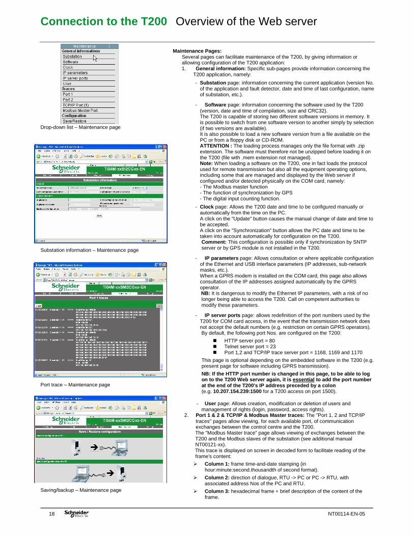
Drop-down list – Maintenance page Substation information – Maintenance page Port trace – Maintenance page Saving/backup – Maintenance page
Maintenance Pages:
Several pages can facilitate maintenance of the T200, by giving information or allowing configuration of the T200 application: 1. General information: Specific sub-pages provide information concerning the
T200 application, namely:
- Substation page: information concerning the current application (version No. of the application and fault detector, date and time of last configuration, name of substation, etc.).
- Software page: information concerning the software used by the T200 (version, date and time of compilation, size and CRC32). The T200 is capable of storing two different software versions in memory. It is possible to switch from one software version to another simply by selection (if two versions are available). It is also possible to load a new software version from a file available on the PC or from a floppy disk or CD-ROM. ATTENTION : The loading process manages only the file format with .zip extension. The software must therefore not be unzipped before loading it on the T200 (file with .mem extension not managed). Note: When loading a software on the T200, one in fact loads the protocol used for remote transmission but also all the equipment operating options, including some that are managed and displayed by the Web server if configured and/or detected physically on the COM card, namely: - The Modbus master function - The function of synchronization by GPS - The digital input counting function.
- Clock page: Allows the T200 date and time to be configured manually or automatically from the time on the PC. A click on the "Update" button causes the manual change of date and time to be accepted. A click on the "Synchronization" button allows the PC date and time to be taken into account automatically for configuration on the T200. Comment: This configuration is possible only if synchronization by SNTP server or by GPS module is not installed in the T200.
- IP parameters page: Allows consultation or where applicable configuration of the Ethernet and USB interface parameters (IP addresses, sub-network masks, etc.). When a GPRS modem is installed on the COM card, this page also allows consultation of the IP addresses assigned automatically by the GPRS operator. NB: It is dangerous to modify the Ethernet IP parameters, with a risk of no longer being able to access the T200. Call on competent authorities to modify these parameters.
- IP server ports page: allows redefinition of the port numbers used by the T200 for COM card access, in the event that the transmission network does not accept the default numbers (e.g. restriction on certain GPRS operators). By default, the following port Nos. are configured on the T200:
� HTTP server port = 80 � Telnet server port = 23 � Port 1,2 and TCP/IP trace server port = 1168, 1169 and 1170
This page is optional depending on the embedded software in the T200 (e.g. present page for software including GPRS transmission).
NB: If the HTTP port number is changed in this page , to be able to log on to the T200 Web server again, it is essential to add the port number at the end of the T200's IP address preceded by a c olon (e.g. 10.207.154.239:1500 for a T200 access on port 1500).
- User page: Allows creation, modification or deletion of users and management of rights (login, password, access rights).
2. Port 1 & 2 & TCP/IP & Modbus Master traces: The "Port 1, 2 and TCP/IP traces" pages allow viewing, for each available port, of communication exchanges between the control centre and the T200. The "Modbus Master trace" page allows viewing of exchanges between the T200 and the Modbus slaves of the substation (see additional manual NT00121-xx). This trace is displayed on screen in decoded form to facilitate reading of the frame's content:
� Column 1: frame time-and-date stamping (in hour:minute:second.thousandth of second format).
� Column 2: direction of dialogue, RTU -> PC or PC -> RTU, with associated address Nos of the PC and RTU.
� Column 3: hexadecimal frame + brief description of the content of the frame.
Connection to the T200 Overview of the Web server
NT00114-EN-05 19
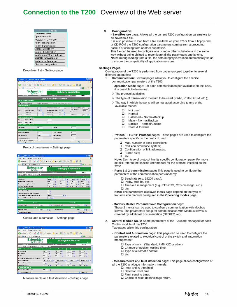
Drop-down list – Settings page Protocol parameters – Settings page Control and automation – Settings page Measurements and fault detection – Settings page
3. Configuration: - Save/Restore page: Allows all the current T200 configuration parameters to be saved to a file. It is also possible to load from a file available on your PC or from a floppy disk or CD-ROM the T200 configuration parameters coming from a preceding backup or coming from another substation. This file can be used to configure one or more other substations in the same way without being obliged to reconfigure all the parameters one by one. Note: During loading from a file, the data integrity is verified automatically so as to ensure the compatibility of application versions.
Seetings Pages Configuration of the T200 is performed from pages grouped together in several different categories: 1. Communication: Several pages allow you to configure the specific
communication parameters of the T200:
- Operation Mode page: For each communication port available on the T200, it is possible to determine:
� The protocol available;
� The type of transmission medium to be used (Radio, PSTN, GSM, etc.);
� The way in which the ports will be managed according to one of the available modes:
� Not used � Normal � Balanced – Normal/Backup � Main – Normal/Backup � Backup – Normal/Backup � Store & forward
- Protocol + TCP/IP Protocol pages: These pages are used to configure the parameters specific to the protocol used:
� Max. number of send operations � Collision avoidance system; � Configuration of link addresses; � Frame size; � etc.
Note: Each type of protocol has its specific configuration page. For more details, refer to the specific user manual for the protocol installed on the T200.
- Ports 1 & 2 transmission page: This page is used to configure the parameters of the communication port (modem):
� Baud rate (e.g. 19200 baud); � Parity, stop bit, etc.; � Time-out management (e.g. RTS-CTS, CTS-message, etc.); � etc.
Note: The parameters displayed in this page depend on the type of transmission medium configured in the Operating modes page.
- Modbus Master Port and Slave Configuration page: These 2 menus can be used to configure communication with Modbus slaves. The parameters setup for communication with Modbus slaves is covered by additional documentation (NT00121-xx).
2. Control Module No. x: Some parameters of the T200 are managed for each
Control module of the T200. Two pages allow this configuration:
- Control and Automation page: This page can be used to configure the parameters related to electrical control of the switch and automation management:
� Type of switch (Standard, PM6, CI2 or other); � Change-of-position waiting time; � Type of automatic control; � etc.
- Measurements and fault detection page: This page allows configuration of all the T200 analogue information, namely:
� Imax and I0 threshold � Detector reset time � Fault sensing times � Choice of reset upon voltage return.
Connection to the T200 Overview of the Web server
20 NT00114-EN-05
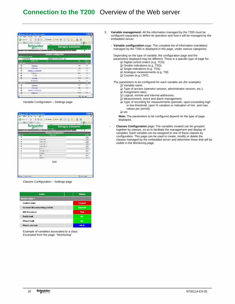
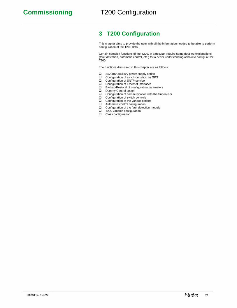
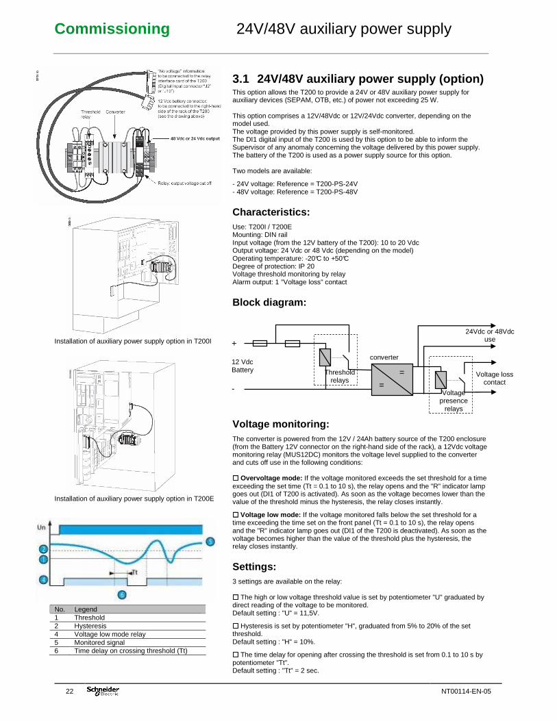
Variable Configuration – Settings page Classes Configuration – Settings page Example of variables associated to a class Excerpted from the page: "Monitoring"
3. Variable management: All the information managed by the T200 must be configured separately to define its operation and how it will be managed by the embedded server: - Variable configuration page: The complete list of information (variables)
managed by the T200 is displayed in this page, under various categories. Depending on the type of variable, the configuration page and the parameters displayed may be different. There is a specific type of page for:
� Digital control orders (e.g. TCD) � Double indications (e.g. TSD) � Single indications (e.g. TSS) � Analogue measurements (e.g. TM) � Counter (e.g. CNT).
The parameters to be configured for each variable are (for example):
� Variable name � Type of access (operator session, administrator session, etc.); � Assignment class; � Logical, remote and internal addresses; � Measurement, event and alarm management; � Type of recording for measurements (periodic, upon exceeding high
or low threshold, upon % variation or indication of min. and max. values per period);
� etc.
Note: The parameters to be configured depend on the type of page displayed.
- Classes Configuration page: The variables created can be grouped together by classes, so as to facilitate the management and display of variables. Each variable can be assigned to one of these classes by configuration. This page can be used to create, modify or delete the classes managed by the embedded server and determine those that will be visible in the Monitoring page.
Commissioning T200 Configuration
NT00114-EN-05 21
3 T200 Configuration This chapter aims to provide the user with all the information needed to be able to perform configuration of the T200 data. Certain complex functions of the T200, in particular, require some detailed explanations (fault detection, automatic control, etc.) for a better understanding of how to configure the T200. The functions discussed in this chapter are as follows: � 24V/48V auxiliary power supply option � Configuration of synchronization by GPS � Configuration of SNTP service � Configuration of Ethernet interfaces � Backup/Restoral of configuration parameters � Dummy Control option � Configuration of communication with the Supervisor � Configuration of switch controls � Configuration of the various options � Automatic control configuration � Configuration of the fault detection module � T200 variable configuration � Class configuration
Commissioning 24V/48V auxiliary power supply
22 NT00114-EN-05
Installation of auxiliary power supply option in T200I Installation of auxiliary power supply option in T200E No. Legend 1 Threshold 2 Hysteresis 4 Voltage low mode relay 5 Monitored signal 6 Time delay on crossing threshold (Tt)
3.1 24V/48V auxiliary power supply (option) This option allows the T200 to provide a 24V or 48V auxiliary power supply for auxiliary devices (SEPAM, OTB, etc.) of power not exceeding 25 W. This option comprises a 12V/48Vdc or 12V/24Vdc converter, depending on the model used. The voltage provided by this power supply is self-monitored. The DI1 digital input of the T200 is used by this option to be able to inform the Supervisor of any anomaly concerning the voltage delivered by this power supply. The battery of the T200 is used as a power supply source for this option. Two models are available:
- 24V voltage: Reference = T200-PS-24V - 48V voltage: Reference = T200-PS-48V
Characteristics: Use: T200I / T200E Mounting: DIN rail Input voltage (from the 12V battery of the T200): 10 to 20 Vdc Output voltage: 24 Vdc or 48 Vdc (depending on the model) Operating temperature: -20°C to +50°C Degree of protection: IP 20 Voltage threshold monitoring by relay Alarm output: 1 "Voltage loss" contact
Block diagram:
Voltage monitoring: The converter is powered from the 12V / 24Ah battery source of the T200 enclosure (from the Battery 12V connector on the right-hand side of the rack), a 12Vdc voltage monitoring relay (MUS12DC) monitors the voltage level supplied to the converter and cuts off use in the following conditions: ���� Overvoltage mode: If the voltage monitored exceeds the set threshold for a time exceeding the set time (Tt = 0.1 to 10 s), the relay opens and the "R" indicator lamp goes out (DI1 of T200 is activated). As soon as the voltage becomes lower than the value of the threshold minus the hysteresis, the relay closes instantly.
���� Voltage low mode: If the voltage monitored falls below the set threshold for a time exceeding the time set on the front panel (Tt = 0.1 to 10 s), the relay opens and the "R" indicator lamp goes out (DI1 of the T200 is deactivated). As soon as the voltage becomes higher than the value of the threshold plus the hysteresis, the relay closes instantly.
Settings: 3 settings are available on the relay: ���� The high or low voltage threshold value is set by potentiometer "U" graduated by direct reading of the voltage to be monitored. Default setting : "U" = 11,5V.
���� Hysteresis is set by potentiometer "H", graduated from 5% to 20% of the set threshold. Default setting : "H" = 10%.
���� The time delay for opening after crossing the threshold is set from 0.1 to 10 s by potentiometer "Tt". Default setting : "Tt" = 2 sec.
+
12 Vdc Battery -
Threshold relays
converter
24Vdc or 48Vdc use
Voltage loss contact
Voltage presence
relays
=
=
Commissioning GPS synchronization setting
NT00114-EN-05 23
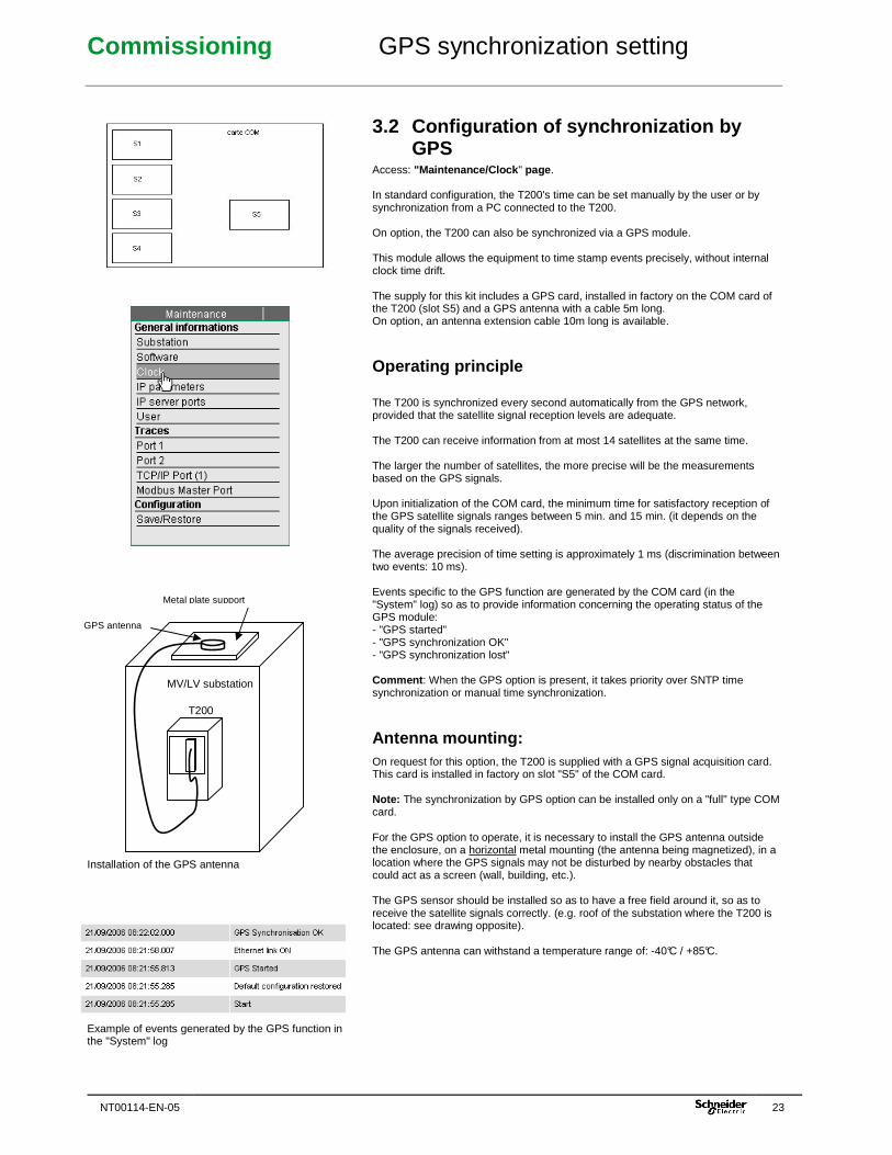
Installation of the GPS antenna Example of events generated by the GPS function in the "System" log
3.2 Configuration of synchronization by GPS
Access: "Maintenance/Clock " page . In standard configuration, the T200's time can be set manually by the user or by synchronization from a PC connected to the T200. On option, the T200 can also be synchronized via a GPS module. This module allows the equipment to time stamp events precisely, without internal clock time drift. The supply for this kit includes a GPS card, installed in factory on the COM card of the T200 (slot S5) and a GPS antenna with a cable 5m long. On option, an antenna extension cable 10m long is available.
Operating principle The T200 is synchronized every second automatically from the GPS network, provided that the satellite signal reception levels are adequate. The T200 can receive information from at most 14 satellites at the same time. The larger the number of satellites, the more precise will be the measurements based on the GPS signals. Upon initialization of the COM card, the minimum time for satisfactory reception of the GPS satellite signals ranges between 5 min. and 15 min. (it depends on the quality of the signals received). The average precision of time setting is approximately 1 ms (discrimination between two events: 10 ms). Events specific to the GPS function are generated by the COM card (in the "System" log) so as to provide information concerning the operating status of the GPS module: - "GPS started" - "GPS synchronization OK" - "GPS synchronization lost" Comment : When the GPS option is present, it takes priority over SNTP time synchronization or manual time synchronization.
Antenna mounting: On request for this option, the T200 is supplied with a GPS signal acquisition card. This card is installed in factory on slot "S5" of the COM card. Note: The synchronization by GPS option can be installed only on a "full" type COM card. For the GPS option to operate, it is necessary to install the GPS antenna outside the enclosure, on a horizontal metal mounting (the antenna being magnetized), in a location where the GPS signals may not be disturbed by nearby obstacles that could act as a screen (wall, building, etc.). The GPS sensor should be installed so as to have a free field around it, so as to receive the satellite signals correctly. (e.g. roof of the substation where the T200 is located: see drawing opposite). The GPS antenna can withstand a temperature range of: -40°C / +85°C.
T200
MV/LV substation
Metal plate support
GPS antenna
Commissioning GPS synchronization setting
24 NT00114-EN-05
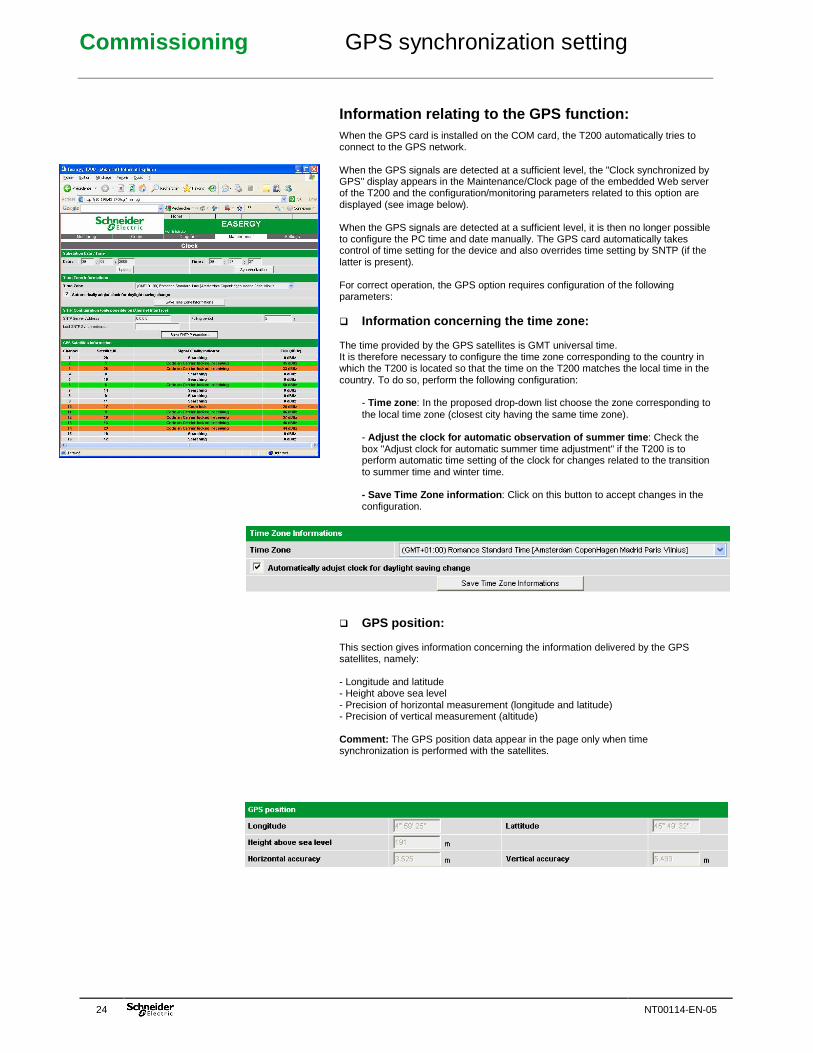
Information relating to the GPS function: When the GPS card is installed on the COM card, the T200 automatically tries to connect to the GPS network. When the GPS signals are detected at a sufficient level, the "Clock synchronized by GPS" display appears in the Maintenance/Clock page of the embedded Web server of the T200 and the configuration/monitoring parameters related to this option are displayed (see image below). When the GPS signals are detected at a sufficient level, it is then no longer possible to configure the PC time and date manually. The GPS card automatically takes control of time setting for the device and also overrides time setting by SNTP (if the latter is present). For correct operation, the GPS option requires configuration of the following parameters: � Information concerning the time zone: The time provided by the GPS satellites is GMT universal time. It is therefore necessary to configure the time zone corresponding to the country in which the T200 is located so that the time on the T200 matches the local time in the country. To do so, perform the following configuration:
- Time zone : In the proposed drop-down list choose the zone corresponding to the local time zone (closest city having the same time zone). - Adjust the clock for automatic observation of summe r time : Check the box "Adjust clock for automatic summer time adjustment" if the T200 is to perform automatic time setting of the clock for changes related to the transition to summer time and winter time. - Save Time Zone information : Click on this button to accept changes in the configuration.
� GPS position: This section gives information concerning the information delivered by the GPS satellites, namely: - Longitude and latitude - Height above sea level - Precision of horizontal measurement (longitude and latitude) - Precision of vertical measurement (altitude) Comment: The GPS position data appear in the page only when time synchronization is performed with the satellites.
Commissioning GPS synchronization setting
NT00114-EN-05 25
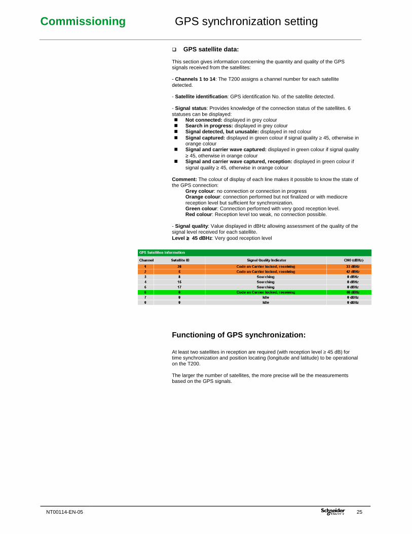
� GPS satellite data: This section gives information concerning the quantity and quality of the GPS signals received from the satellites: - Channels 1 to 14 : The T200 assigns a channel number for each satellite detected. - Satellite identification : GPS identification No. of the satellite detected. - Signal status : Provides knowledge of the connection status of the satellites. 6 statuses can be displayed: � Not connected: displayed in grey colour � Search in progress: displayed in grey colour � Signal detected, but unusable: displayed in red colour � Signal captured: displayed in green colour if signal quality ≥ 45, otherwise in
orange colour � Signal and carrier wave captured: displayed in green colour if signal quality
≥ 45, otherwise in orange colour � Signal and carrier wave captured, reception: displayed in green colour if
signal quality ≥ 45, otherwise in orange colour Comment: The colour of display of each line makes it possible to know the state of the GPS connection:
Grey colour : no connection or connection in progress Orange colour : connection performed but not finalized or with mediocre reception level but sufficient for synchronization. Green colour : Connection performed with very good reception level. Red colour : Reception level too weak, no connection possible.
- Signal quality : Value displayed in dBHz allowing assessment of the quality of the signal level received for each satellite. Level ≥≥≥≥ 45 dBHz : Very good reception level
Functioning of GPS synchronization: At least two satellites in reception are required (with reception level ≥ 45 dB) for time synchronization and position locating (longitude and latitude) to be operational on the T200. The larger the number of satellites, the more precise will be the measurements based on the GPS signals.
Commissioning SNTP service setting
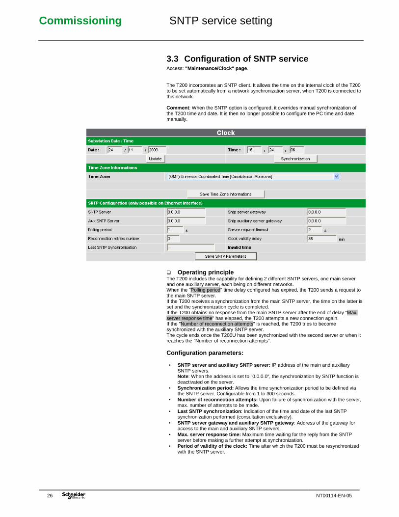
26 NT00114-EN-05
3.3 Configuration of SNTP service Access: "Maintenance/Clock" page . The T200 incorporates an SNTP client. It allows the time on the internal clock of the T200 to be set automatically from a network synchronization server, when T200 is connected to this network. Comment : When the SNTP option is configured, it overrides manual synchronization of the T200 time and date. It is then no longer possible to configure the PC time and date manually. � Operating principle The T200 includes the capability for defining 2 different SNTP servers, one main server and one auxiliary server, each being on different networks. When the "Polling period" time delay configured has expired, the T200 sends a request to the main SNTP server. If the T200 receives a synchronization from the main SNTP server, the time on the latter is set and the synchronization cycle is completed. If the T200 obtains no response from the main SNTP server after the end of delay "Max. server response time" has elapsed, the T200 attempts a new connection again. If the "Number of reconnection attempts" is reached, the T200 tries to become synchronized with the auxiliary SNTP server. The cycle ends once the T200U has been synchronized with the second server or when it reaches the "Number of reconnection attempts". Configuration parameters: • SNTP server and auxiliary SNTP server: IP address of the main and auxiliary
SNTP servers. Note : When the address is set to "0.0.0.0", the synchronization by SNTP function is deactivated on the server.
• Synchronization period: Allows the time synchronization period to be defined via the SNTP server. Configurable from 1 to 300 seconds.
• Number of reconnection attempts: Upon failure of synchronization with the server, max. number of attempts to be made.
• Last SNTP synchronization : Indication of the time and date of the last SNTP synchronization performed (consultation exclusively).
• SNTP server gateway and auxiliary SNTP gateway : Address of the gateway for access to the main and auxiliary SNTP servers.
• Max. server response time: Maximum time waiting for the reply from the SNTP server before making a further attempt at synchronization.
• Period of validity of the clock: Time after which the T200 must be resynchronized with the SNTP server.
Commissioning Ethernet interface setting
NT00114-EN-05 27
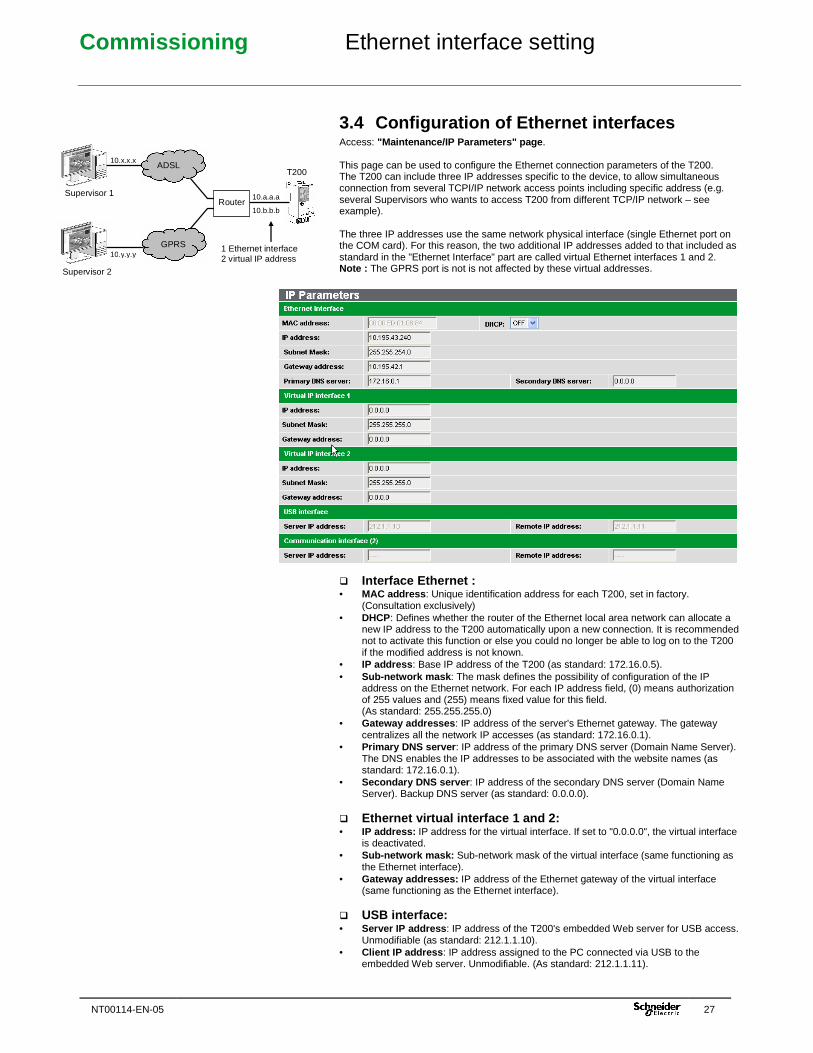
3.4 Configuration of Ethernet interfaces Access: "Maintenance/IP Parameters" page . This page can be used to configure the Ethernet connection parameters of the T200. The T200 can include three IP addresses specific to the device, to allow simultaneous connection from several TCPI/IP network access points including specific address (e.g. several Supervisors who wants to access T200 from different TCP/IP network – see example). The three IP addresses use the same network physical interface (single Ethernet port on the COM card). For this reason, the two additional IP addresses added to that included as standard in the "Ethernet Interface" part are called virtual Ethernet interfaces 1 and 2. Note : The GPRS port is not is not affected by these virtual addresses. � Interface Ethernet : • MAC address : Unique identification address for each T200, set in factory.
(Consultation exclusively) • DHCP: Defines whether the router of the Ethernet local area network can allocate a
new IP address to the T200 automatically upon a new connection. It is recommended not to activate this function or else you could no longer be able to log on to the T200 if the modified address is not known.
• IP address : Base IP address of the T200 (as standard: 172.16.0.5). • Sub-network mask : The mask defines the possibility of configuration of the IP
address on the Ethernet network. For each IP address field, (0) means authorization of 255 values and (255) means fixed value for this field. (As standard: 255.255.255.0)
• Gateway addresses : IP address of the server's Ethernet gateway. The gateway centralizes all the network IP accesses (as standard: 172.16.0.1).
• Primary DNS server : IP address of the primary DNS server (Domain Name Server). The DNS enables the IP addresses to be associated with the website names (as standard: 172.16.0.1).
• Secondary DNS server : IP address of the secondary DNS server (Domain Name Server). Backup DNS server (as standard: 0.0.0.0).
� Ethernet virtual interface 1 and 2: • IP address: IP address for the virtual interface. If set to "0.0.0.0", the virtual interface
is deactivated. • Sub-network mask: Sub-network mask of the virtual interface (same functioning as
the Ethernet interface). • Gateway addresses: IP address of the Ethernet gateway of the virtual interface
(same functioning as the Ethernet interface). � USB interface: • Server IP address : IP address of the T200's embedded Web server for USB access.
Unmodifiable (as standard: 212.1.1.10). • Client IP address : IP address assigned to the PC connected via USB to the
embedded Web server. Unmodifiable. (As standard: 212.1.1.11).
T200
Supervisor 1
Supervisor 2
ADSL
GPRS 1 Ethernet interface 2 virtual IP address
10.x.x.x
10.a.a.a
10.y.y.y
10.b.b.b Router
Commissioning Save/Restore configuration
28 NT00114-EN-05
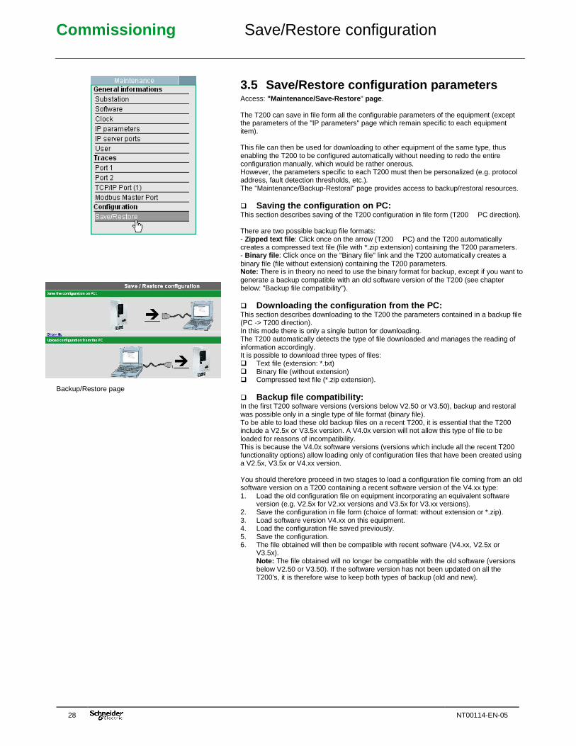
Backup/Restore page
3.5 Save/Restore configuration parameters Access: "Maintenance/Save-Restore " page . The T200 can save in file form all the configurable parameters of the equipment (except the parameters of the "IP parameters" page which remain specific to each equipment item). This file can then be used for downloading to other equipment of the same type, thus enabling the T200 to be configured automatically without needing to redo the entire configuration manually, which would be rather onerous. However, the parameters specific to each T200 must then be personalized (e.g. protocol address, fault detection thresholds, etc.). The "Maintenance/Backup-Restoral" page provides access to backup/restoral resources. � Saving the configuration on PC: This section describes saving of the T200 configuration in file form (T200 � PC direction). There are two possible backup file formats: - Zipped text file : Click once on the arrow (T200 � PC) and the T200 automatically creates a compressed text file (file with *.zip extension) containing the T200 parameters. - Binary file : Click once on the "Binary file" link and the T200 automatically creates a binary file (file without extension) containing the T200 parameters. Note: There is in theory no need to use the binary format for backup, except if you want to generate a backup compatible with an old software version of the T200 (see chapter below: "Backup file compatibility"). � Downloading the configuration from the PC: This section describes downloading to the T200 the parameters contained in a backup file (PC -> T200 direction). In this mode there is only a single button for downloading. The T200 automatically detects the type of file downloaded and manages the reading of information accordingly. It is possible to download three types of files: � Text file (extension: *.txt) � Binary file (without extension) � Compressed text file (*.zip extension). � Backup file compatibility: In the first T200 software versions (versions below V2.50 or V3.50), backup and restoral was possible only in a single type of file format (binary file). To be able to load these old backup files on a recent T200, it is essential that the T200 include a V2.5x or V3.5x version. A V4.0x version will not allow this type of file to be loaded for reasons of incompatibility. This is because the V4.0x software versions (versions which include all the recent T200 functionality options) allow loading only of configuration files that have been created using a V2.5x, V3.5x or V4.xx version. You should therefore proceed in two stages to load a configuration file coming from an old software version on a T200 containing a recent software version of the V4.xx type: 1. Load the old configuration file on equipment incorporating an equivalent software
version (e.g. V2.5x for V2.xx versions and V3.5x for V3.xx versions). 2. Save the configuration in file form (choice of format: without extension or *.zip). 3. Load software version V4.xx on this equipment. 4. Load the configuration file saved previously. 5. Save the configuration. 6. The file obtained will then be compatible with recent software (V4.xx, V2.5x or
V3.5x). Note: The file obtained will no longer be compatible with the old software (versions below V2.50 or V3.50). If the software version has not been updated on all the T200's, it is therefore wise to keep both types of backup (old and new).
Commissioning Dummy control
NT00114-EN-05 29
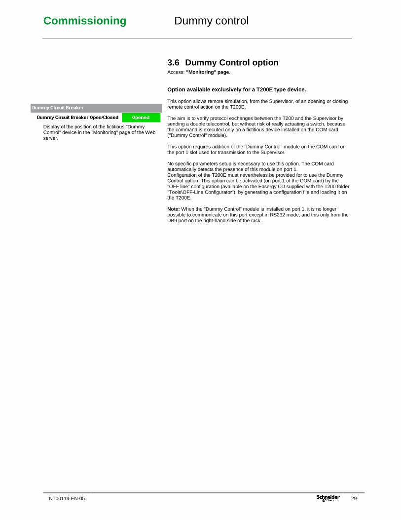
Display of the position of the fictitious "Dummy Control" device in the "Monitoring" page of the Web server.
3.6 Dummy Control option Access: "Monitoring" page . Option available exclusively for a T200E type devic e. This option allows remote simulation, from the Supervisor, of an opening or closing remote control action on the T200E. The aim is to verify protocol exchanges between the T200 and the Supervisor by sending a double telecontrol, but without risk of really actuating a switch, because the command is executed only on a fictitious device installed on the COM card ("Dummy Control" module). This option requires addition of the "Dummy Control" module on the COM card on the port 1 slot used for transmission to the Supervisor. No specific parameters setup is necessary to use this option. The COM card automatically detects the presence of this module on port 1. Configuration of the T200E must nevertheless be provided for to use the Dummy Control option. This option can be activated (on port 1 of the COM card) by the "OFF line" configuration (available on the Easergy CD supplied with the T200 folder "Tools\OFF-Line Configurator"), by generating a configuration file and loading it on the T200E. Note: When the "Dummy Control" module is installed on port 1, it is no longer possible to communicate on this port except in RS232 mode, and this only from the DB9 port on the right-hand side of the rack..
Commissioning Communication configuration
30 NT00114-EN-05
Excerpted from the page: "Settings/Operating mode"
3.7 Parameters for communication with the supervisor
The COM card of the T200 is designed to detect automatically the type of modem that is installed on the communication ports used for transmission to the SCADA system (ports 1 and 2). The configuration software automatically proposes a choice of media on these ports which will correspond to the type of modem installed. The parameters present in the configuration pages for ports 1 and 2 take into account the type of medium that has been selected, because each type of medium has specific configuration parameters. The configuration page for protocol parameters may take also into account certain parameters related to the type of medium selected. Comment: The protocol parameters related to the type of medium will be described in this chapter. The other parameters related to the protocol will not be described in detail, however. For more information concerning the latter, refer to the User's Manual for the protocol.
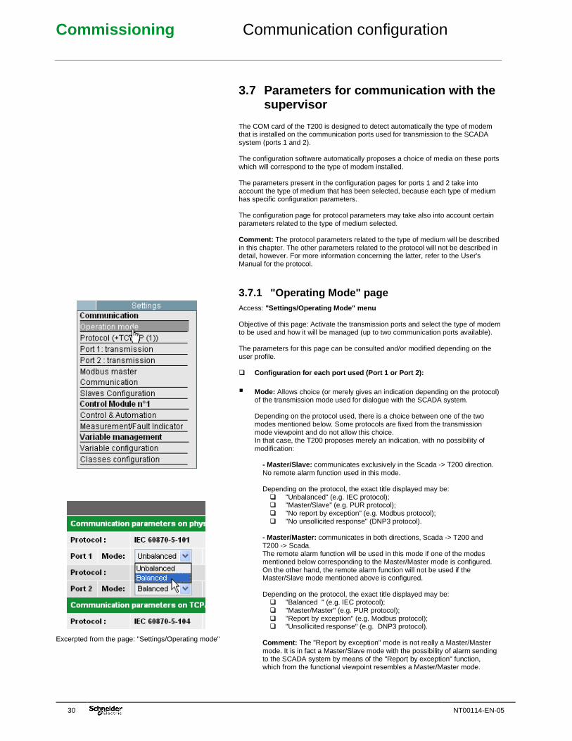
3.7.1 "Operating Mode" page Access: "Settings/Operating Mode" menu Objective of this page: Activate the transmission ports and select the type of modem to be used and how it will be managed (up to two communication ports available). The parameters for this page can be consulted and/or modified depending on the user profile. � Configuration for each port used (Port 1 or Port 2) :
� Mode: Allows choice (or merely gives an indication depending on the protocol) of the transmission mode used for dialogue with the SCADA system. Depending on the protocol used, there is a choice between one of the two modes mentioned below. Some protocols are fixed from the transmission mode viewpoint and do not allow this choice. In that case, the T200 proposes merely an indication, with no possibility of modification:
- Master/Slave: communicates exclusively in the Scada -> T200 direction. No remote alarm function used in this mode. Depending on the protocol, the exact title displayed may be:
� "Unbalanced" (e.g. IEC protocol); � "Master/Slave" (e.g. PUR protocol); � "No report by exception" (e.g. Modbus protocol); � "No unsollicited response" (DNP3 protocol).
- Master/Master: communicates in both directions, Scada -> T200 and T200 -> Scada. The remote alarm function will be used in this mode if one of the modes mentioned below corresponding to the Master/Master mode is configured. On the other hand, the remote alarm function will not be used if the Master/Slave mode mentioned above is configured. Depending on the protocol, the exact title displayed may be:
� "Balanced " (e.g. IEC protocol); � "Master/Master" (e.g. PUR protocol); � "Report by exception" (e.g. Modbus protocol); � "Unsollicited response" (e.g. DNP3 protocol).
Comment: The "Report by exception" mode is not really a Master/Master mode. It is in fact a Master/Slave mode with the possibility of alarm sending to the SCADA system by means of the "Report by exception" function, which from the functional viewpoint resembles a Master/Master mode.
Commissioning Communication configuration
NT00114-EN-05 31
From the page: "Settings/Operating mode"
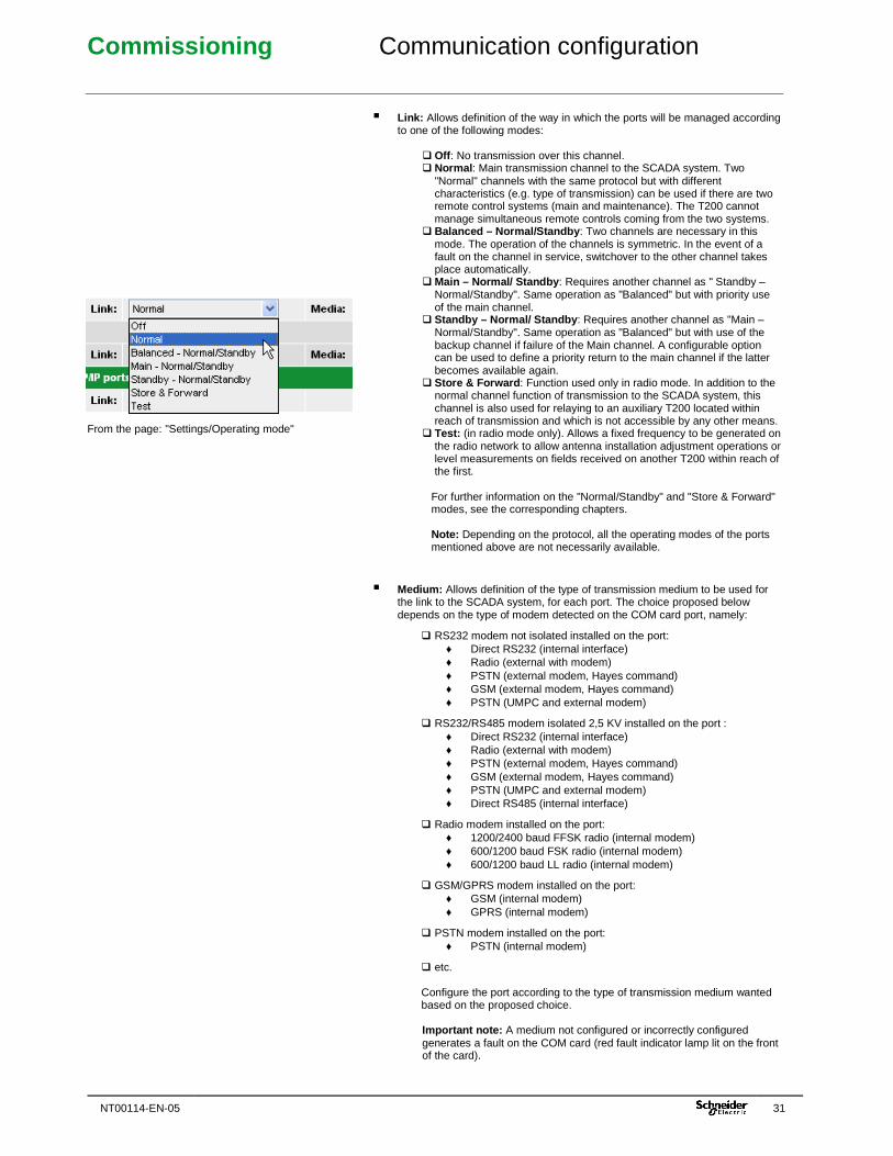
� Link: Allows definition of the way in which the ports will be managed according to one of the following modes:
� Off : No transmission over this channel. � Normal : Main transmission channel to the SCADA system. Two
"Normal" channels with the same protocol but with different characteristics (e.g. type of transmission) can be used if there are two remote control systems (main and maintenance). The T200 cannot manage simultaneous remote controls coming from the two systems.
� Balanced – Normal/Standby : Two channels are necessary in this mode. The operation of the channels is symmetric. In the event of a fault on the channel in service, switchover to the other channel takes place automatically.
� Main – Normal/ Standby : Requires another channel as " Standby – Normal/Standby". Same operation as "Balanced" but with priority use of the main channel.
� Standby – Normal/ Standby : Requires another channel as "Main – Normal/Standby". Same operation as "Balanced" but with use of the backup channel if failure of the Main channel. A configurable option can be used to define a priority return to the main channel if the latter becomes available again.
� Store & Forward : Function used only in radio mode. In addition to the normal channel function of transmission to the SCADA system, this channel is also used for relaying to an auxiliary T200 located within reach of transmission and which is not accessible by any other means.
� Test: (in radio mode only). Allows a fixed frequency to be generated on the radio network to allow antenna installation adjustment operations or level measurements on fields received on another T200 within reach of the first.
For further information on the "Normal/Standby" and "Store & Forward" modes, see the corresponding chapters. Note: Depending on the protocol, all the operating modes of the ports mentioned above are not necessarily available.
� Medium: Allows definition of the type of transmission medium to be used for the link to the SCADA system, for each port. The choice proposed below depends on the type of modem detected on the COM card port, namely:
� RS232 modem not isolated installed on the port: ♦ Direct RS232 (internal interface) ♦ Radio (external with modem) ♦ PSTN (external modem, Hayes command) ♦ GSM (external modem, Hayes command) ♦ PSTN (UMPC and external modem)
� RS232/RS485 modem isolated 2,5 KV installed on the port : ♦ Direct RS232 (internal interface) ♦ Radio (external with modem) ♦ PSTN (external modem, Hayes command) ♦ GSM (external modem, Hayes command) ♦ PSTN (UMPC and external modem) ♦ Direct RS485 (internal interface)
� Radio modem installed on the port: ♦ 1200/2400 baud FFSK radio (internal modem) ♦ 600/1200 baud FSK radio (internal modem) ♦ 600/1200 baud LL radio (internal modem)
� GSM/GPRS modem installed on the port: ♦ GSM (internal modem) ♦ GPRS (internal modem)
� PSTN modem installed on the port: ♦ PSTN (internal modem)
� etc. Configure the port according to the type of transmission medium wanted based on the proposed choice. Important note: A medium not configured or incorrectly configured generates a fault on the COM card (red fault indicator lamp lit on the front of the card).
Commissioning Communication configuration
32 NT00114-EN-05
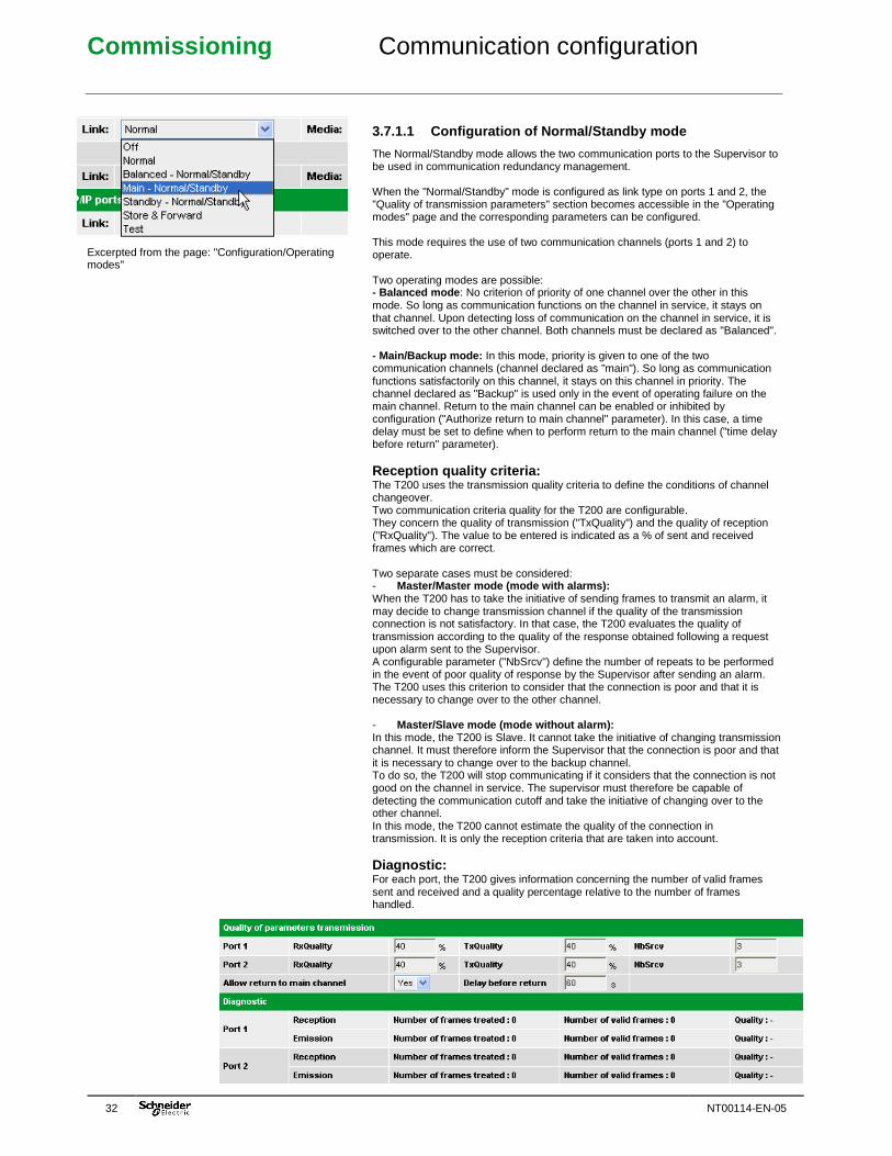
Excerpted from the page: "Configuration/Operating modes"
3.7.1.1 Configuration of Normal/Standby mode
The Normal/Standby mode allows the two communication ports to the Supervisor to be used in communication redundancy management. When the "Normal/Standby" mode is configured as link type on ports 1 and 2, the "Quality of transmission parameters" section becomes accessible in the "Operating modes" page and the corresponding parameters can be configured. This mode requires the use of two communication channels (ports 1 and 2) to operate. Two operating modes are possible: - Balanced mode : No criterion of priority of one channel over the other in this mode. So long as communication functions on the channel in service, it stays on that channel. Upon detecting loss of communication on the channel in service, it is switched over to the other channel. Both channels must be declared as "Balanced". - Main/Backup mode: In this mode, priority is given to one of the two communication channels (channel declared as "main"). So long as communication functions satisfactorily on this channel, it stays on this channel in priority. The channel declared as "Backup" is used only in the event of operating failure on the main channel. Return to the main channel can be enabled or inhibited by configuration ("Authorize return to main channel" parameter). In this case, a time delay must be set to define when to perform return to the main channel ("time delay before return" parameter).
Reception quality criteria: The T200 uses the transmission quality criteria to define the conditions of channel changeover. Two communication criteria quality for the T200 are configurable. They concern the quality of transmission ("TxQuality") and the quality of reception ("RxQuality"). The value to be entered is indicated as a % of sent and received frames which are correct. Two separate cases must be considered: - Master/Master mode (mode with alarms): When the T200 has to take the initiative of sending frames to transmit an alarm, it may decide to change transmission channel if the quality of the transmission connection is not satisfactory. In that case, the T200 evaluates the quality of transmission according to the quality of the response obtained following a request upon alarm sent to the Supervisor. A configurable parameter ("NbSrcv") define the number of repeats to be performed in the event of poor quality of response by the Supervisor after sending an alarm. The T200 uses this criterion to consider that the connection is poor and that it is necessary to change over to the other channel. - Master/Slave mode (mode without alarm): In this mode, the T200 is Slave. It cannot take the initiative of changing transmission channel. It must therefore inform the Supervisor that the connection is poor and that it is necessary to change over to the backup channel. To do so, the T200 will stop communicating if it considers that the connection is not good on the channel in service. The supervisor must therefore be capable of detecting the communication cutoff and take the initiative of changing over to the other channel. In this mode, the T200 cannot estimate the quality of the connection in transmission. It is only the reception criteria that are taken into account.
Diagnostic: For each port, the T200 gives information concerning the number of valid frames sent and received and a quality percentage relative to the number of frames handled.
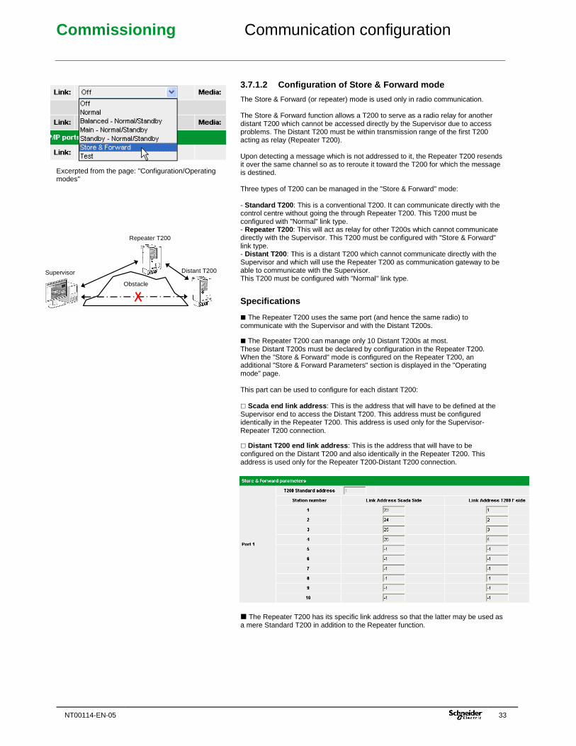
Commissioning Communication configuration
NT00114-EN-05 33
Excerpted from the page: "Configuration/Operating modes"
3.7.1.2 Configuration of Store & Forward mode
The Store & Forward (or repeater) mode is used only in radio communication. The Store & Forward function allows a T200 to serve as a radio relay for another distant T200 which cannot be accessed directly by the Supervisor due to access problems. The Distant T200 must be within transmission range of the first T200 acting as relay (Repeater T200). Upon detecting a message which is not addressed to it, the Repeater T200 resends it over the same channel so as to reroute it toward the T200 for which the message is destined. Three types of T200 can be managed in the "Store & Forward" mode: - Standard T200: This is a conventional T200. It can communicate directly with the control centre without going the through Repeater T200. This T200 must be configured with "Normal" link type. - Repeater T200 : This will act as relay for other T200s which cannot communicate directly with the Supervisor. This T200 must be configured with "Store & Forward" link type. - Distant T200: This is a distant T200 which cannot communicate directly with the Supervisor and which will use the Repeater T200 as communication gateway to be able to communicate with the Supervisor. This T200 must be configured with "Normal" link type.
Specifications � The Repeater T200 uses the same port (and hence the same radio) to communicate with the Supervisor and with the Distant T200s. � The Repeater T200 can manage only 10 Distant T200s at most. These Distant T200s must be declared by configuration in the Repeater T200. When the "Store & Forward" mode is configured on the Repeater T200, an additional "Store & Forward Parameters" section is displayed in the "Operating mode" page. This part can be used to configure for each distant T200: � Scada end link address : This is the address that will have to be defined at the Supervisor end to access the Distant T200. This address must be configured identically in the Repeater T200. This address is used only for the Supervisor-Repeater T200 connection. � Distant T200 end link address : This is the address that will have to be configured on the Distant T200 and also identically in the Repeater T200. This address is used only for the Repeater T200-Distant T200 connection. � The Repeater T200 has its specific link address so that the latter may be used as a mere Standard T200 in addition to the Repeater function.
Repeater T200
Distant T200 Supervisor
Obstacle
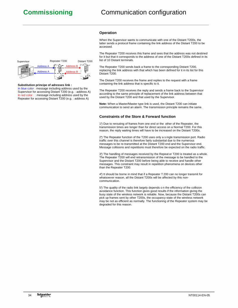
Commissioning Communication configuration
34 NT00114-EN-05
Operation When the Supervisor wants to communicate with one of the Distant T200s, the latter sends a protocol frame containing the link address of the Distant T200 to be accessed. The Repeater T200 receives this frame and sees that the address was not destined for it but that it corresponds to the address of one of the Distant T200s defined in its list of 10 Distant terminals. The Repeater T200 sends back a frame to the corresponding Distant T200, replacing the link address with that which has been defined for it in its list for this Distant T200. The Distant T200 receives the frame and replies to the request with a frame containing the link address that is specific to it. The Repeater T200 receives the reply and sends a frame back to the Supervisor according to the same principle of replacement of the link address between that used by the Distant T200 and that used by the Supervisor. Note: When a Master/Master type link is used, the Distant T200 can initiate communication to send an alarm. The transmission principle remains the same.
Constraints of the Store & Forward function 1°) Due to rerouting of frames from one end or the other of the Repeater, the transmission times are longer than for direct access on a Normal T200. For this reason, the reply waiting times will have to be increased on the Distant T200s. 2°) The Repeater function of the T200 uses only a s ingle transmission port. Radio traffic over this channel is therefore fairly substantial due to the numerous messages to be re-transmitted at the Distant T200 end and the Supervisor end. Message collisions and repetitions must therefore be expected on the radio traffic. 3°) The handling of messages received by the Repeat er T200 is treated as a whole. The Repeater T200 will end retransmission of the message to be handled to the Supervisor and the Distant T200 before being able to receive and handle other messages. This constraint may result in repetition phenomena on devices other than the Repeater T200. 4°) It should be borne in mind that if a Repeater T 200 can no longer transmit for whatsoever reason, all the Distant T200s will be affected by this non-communication. 5°) The quality of the radio link largely depends o n the efficiency of the collision avoidance function. This function gives good results if the information giving the busy state of the wireless network is reliable. Now, because the Distant T200s can pick up frames sent by other T200s, the occupancy state of the wireless network may be not as efficient as normally. The functioning of the Repeater system may be degraded for this reason.
Repeater T200 Distant T200 Supervisor
Address A Address B
Address B Address A
Substitution principe of adresses link : In blue color : message including address used by the Supervisor for accessing Distant T200 (e.g. : address A) In red color : : message including address used by the Repeater for accessing Distant T200 (e.g. : address A)
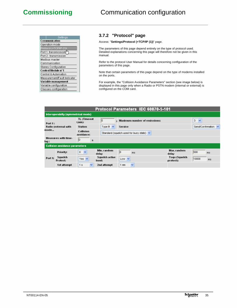
Commissioning Communication configuration
NT00114-EN-05 35
3.7.2 "Protocol" page Access: "Settings/Protocol (+TCP/IP (1)) " page. The parameters of this page depend entirely on the type of protocol used. Detailed explanations concerning this page will therefore not be given in this manual. Refer to the protocol User Manual for details concerning configuration of the parameters of this page. Note that certain parameters of this page depend on the type of modems installed on the ports. For example, the "Collision Avoidance Parameters" section (see image below) is displayed in this page only when a Radio or PSTN modem (internal or external) is configured on the COM card.
Commissioning Communication configuration
36 NT00114-EN-05
3.7.3 "Port 1 (or 2): Transmission" page Access: "Settings/Port X: Transmission" page The parameters display for this page depends on the type of modem installed on the port of the COM card (port 1 or port 2) and on the transmission medium chosen in the "Settings/Operating Mode" page.
Configuration procedure: The T200 is factory-delivered with a default configuration corresponding to the type of modem installed on the COM card (internal modem) or on the sliding plate of the enclosure (external modem). The user should then (if need be) adjust the parameters of this page (in particular the modem management signals and associated time delays) depending on what is required for the modems used or possibly the transmission network. Concerning the adjustment of transmission delays, in theory one starts by configuring high values for all the delays, checking first that dialogue is established between the T200 and the Supervisor. One starts by gradually reducing the first time delay in order to determine the operating limit of the modem relative to the adjusted signal. Then, this delay is increased by several tens of milliseconds to retain a safety margin. The procedure is then started again with the other delays. This method allows T200-Supervisor transmission times to be optimized. In case of doubt concerning the configuration, it is preferable to leave the default values.
Modem management signals: Before going into detail concerning the parameters to be configured, the function of each modem management signal should be explained. The following timing diagram shows the management signals involved during communication between the T200 modem and the interface or the external radio, or even directly with the control centre.
DSR CD Received frame DTR or Send Cd RTS CTS Sent frame Squelch
DSR (Data Send Ready): This signal can be supplied to the T200 to indicate that the Control Centre (or the modem) is capable of transmitting (or simply that it is energized). This signal is used only in the case of an RS232 link (not used in radio mode). CD (Carrier Detect): This signal, when it exists, is used to confirm receipt of the received frame. It can also be used to learn the transmission network occupancy. DTR (Data Terminal Ready): When the Control Centre uses DSR, DTR is used to indicate that the T200 is ready for transmission (equivalent of DSR but in the other direction).
In radio mode with internal modem: This signal is used by the T200 to actuate radio terminal transition to sending when it requires different commands for transition to sending and carrier sending. In radio mode with external modem: This signal is generally not used (with some exceptions) because RTS is used as the sole command to cause rising of the send command and cause rising of the carrier.
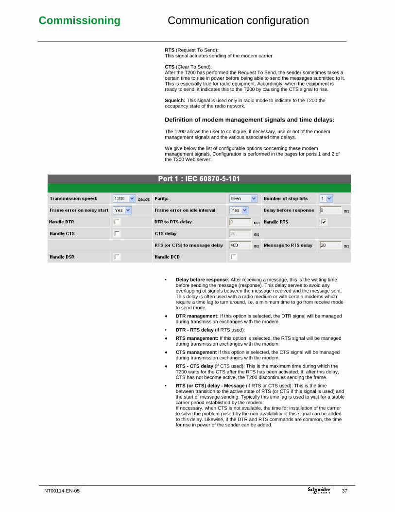
Commissioning Communication configuration
NT00114-EN-05 37
RTS (Request To Send): This signal actuates sending of the modem carrier CTS (Clear To Send): After the T200 has performed the Request To Send, the sender sometimes takes a certain time to rise in power before being able to send the messages submitted to it. This is especially true for radio equipment. Accordingly, when the equipment is ready to send, it indicates this to the T200 by causing the CTS signal to rise. Squelch: This signal is used only in radio mode to indicate to the T200 the occupancy state of the radio network.
Definition of modem management signals and time del ays: The T200 allows the user to configure, if necessary, use or not of the modem management signals and the various associated time delays. We give below the list of configurable options concerning these modem management signals. Configuration is performed in the pages for ports 1 and 2 of the T200 Web server:
• Delay before response : After receiving a message, this is the waiting time before sending the message (response). This delay serves to avoid any overlapping of signals between the message received and the message sent. This delay is often used with a radio medium or with certain modems which require a time lag to turn around, i.e. a minimum time to go from receive mode to send mode.
♦ DTR management: If this option is selected, the DTR signal will be managed during transmission exchanges with the modem.
• DTR - RTS delay (if RTS used):
♦ RTS management: If this option is selected, the RTS signal will be managed during transmission exchanges with the modem.
♦ CTS management If this option is selected, the CTS signal will be managed during transmission exchanges with the modem.
♦ RTS - CTS delay (if CTS used): This is the maximum time during which the T200 waits for the CTS after the RTS has been activated. If, after this delay, CTS has not become active, the T200 discontinues sending the frame.
• RTS (or CTS) delay - Message (if RTS or CTS used): This is the time between transition to the active state of RTS (or CTS if this signal is used) and the start of message sending. Typically this time lag is used to wait for a stable carrier period established by the modem. If necessary, when CTS is not available, the time for installation of the carrier to solve the problem posed by the non-availability of this signal can be added to this delay. Likewise, if the DTR and RTS commands are common, the time for rise in power of the sender can be added.
Commissioning Communication configuration
38 NT00114-EN-05
Note: Example of delay to be configured on the T200, depending on the type of radio: - Motorola CM 340 or GM340 radio: RTS-Message delay = 150 ms - TAIT 811x radio: RTS-Message delay = 100 ms - MDS4710 radio: RTS-Message delay = 50 ms
♦ Message - RTS delay (if RTS used): This is the minimum time to be waited, after sending a message, before causing RTS and DTR (or Send command) to fall again. This delay prevents the end of the message from being truncated by the premature fall of modem sending. Note: Example of delay to be configured on the T200, depending on the type of radio: - Motorola CM 340 or GM340 radio: Message - RTS delay = 100 ms - TAIT 811x radio: Message - RTS delay = 80 ms - MDS4710 radio: Message - RTS delay = 50 ms
♦ DSR management If this option is selected, the DSR signal will be managed during transmission exchanges with the modem.
♦ CD management: If this option is selected, the CD signal will be managed during transmission exchanges with the modem.
General parameters (common to the various transmiss ion media): As a general rule, certain configurable parameters of the ports 1 and 2 pages are common to numerous types of modems. We shall describe in detail here the meaning of these parameters and how to configure them.
♦ Baud rate : This is the speed of transmission between the T200 and the modem. When an external modem is used, the configured speed is not necessarily the speed that will be used for the link to the Supervisor, because the external modem can use a different speed to that used for the RS232-T200 link. The choice of available speeds differs depending on the type of modem installed on the ports. Here are a few examples: � FFSK radio: 1200 or 2400 baud � External radio or internal RS232: 200 to 38400 baud � Internal GSM: 600 to 9600 baud � etc.
♦ Parity: This is the frame character parity for transmission to the Supervisor. Some modems do not manage parity. In such cases, the T200 will have to be configured with the "No parity" option. To be defined therefore according to the type of modem used. Of course, the Control Centre must also be able to be configured in this mode. Note that when the parity is no longer used, transmission security is diminished and a disturbed frame may be considered correct. (See protocol manual for more details concerning this function). There are four possible configurations: no parity, space, even or odd. Note: Parity is not used in PSTN, GSM, GPRS and FFSK radio links.
♦ Number of stop bits: This is the number of stop bits used to define the end of a frame during transmission. There are two possible configurations: one or two stop bits.
• Frame error on idle line: The T200 is capable of detecting a gap greater than 1 bit between 2 characters of a frame. With certain protocols, any frame having this feature can be rejected. This allows secure transmission. This frame rejection will be activated if this option is set to "Yes". This configuration implies that the Supervisor and the modems involved in the transmission circuit ensure that there are no gaps. While this is sometimes true with regard to the Supervisor, it is not completely true for many modems (case of packet transmission). In this specific case, "No" should be set. However, transmission security must then be ensured by other means (see User Manual of the protocol used for more information). Note: This parameter is used only on a radio or LL link.
• Frame error on noisy outgoing cable: Some transmission networks could constantly generate noise just at the start of frame. In that case this option should be set to "No", to avoid systematically rejecting all the received frames which could be considered incorrect. However, the incorrect character generated by the noise located in the frame header will be eliminated when reading the frame, because this character will not correspond to what is expected by the protocol. Note that, in most cases, this noise does not exist. In such cases, the option should be set to "Yes". Note: This parameter is used only on a radio or LL link.
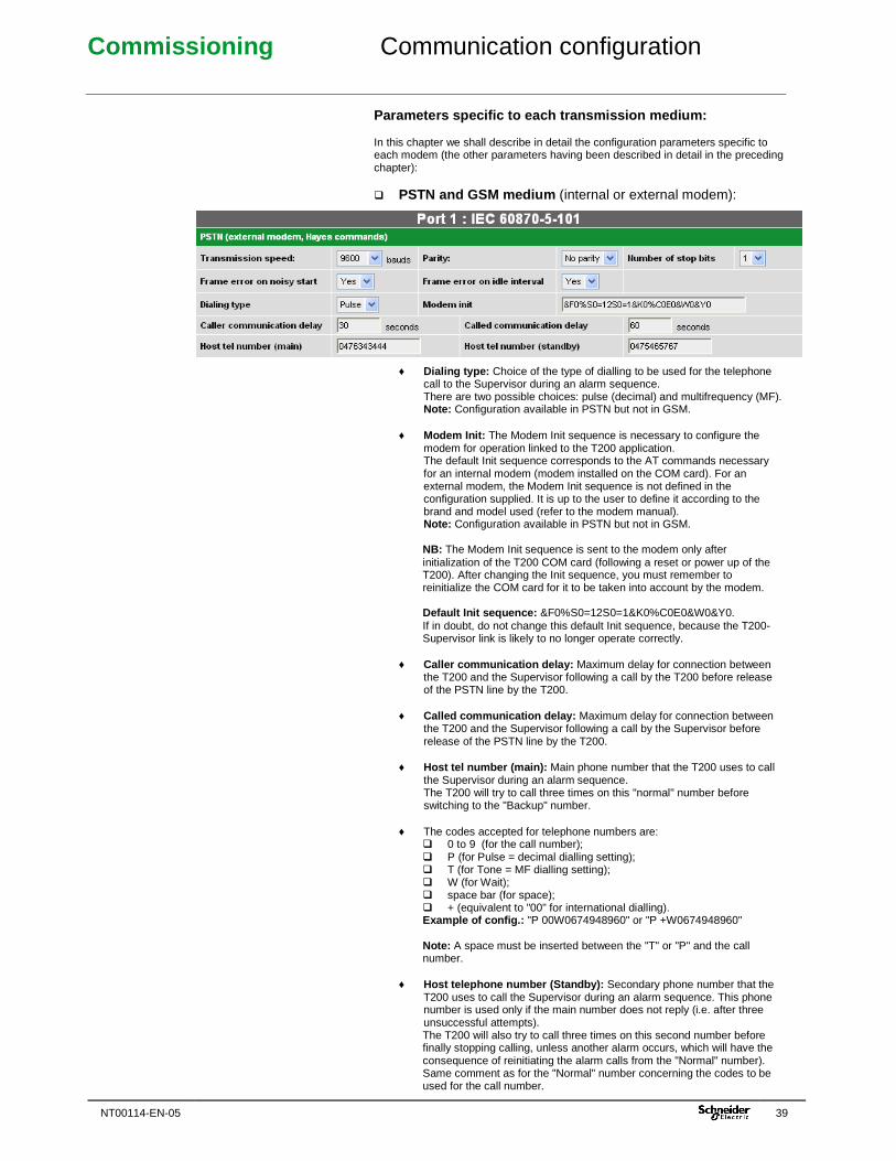
Commissioning Communication configuration
NT00114-EN-05 39
Parameters specific to each transmission medium: In this chapter we shall describe in detail the configuration parameters specific to each modem (the other parameters having been described in detail in the preceding chapter): � PSTN and GSM medium (internal or external modem):
♦ Dialing type: Choice of the type of dialling to be used for the telephone call to the Supervisor during an alarm sequence. There are two possible choices: pulse (decimal) and multifrequency (MF). Note: Configuration available in PSTN but not in GSM.
♦ Modem Init: The Modem Init sequence is necessary to configure the
modem for operation linked to the T200 application. The default Init sequence corresponds to the AT commands necessary for an internal modem (modem installed on the COM card). For an external modem, the Modem Init sequence is not defined in the configuration supplied. It is up to the user to define it according to the brand and model used (refer to the modem manual). Note: Configuration available in PSTN but not in GSM.
NB: The Modem Init sequence is sent to the modem only after initialization of the T200 COM card (following a reset or power up of the T200). After changing the Init sequence, you must remember to reinitialize the COM card for it to be taken into account by the modem. Default Init sequence: &F0%S0=12S0=1&K0%C0E0&W0&Y0. If in doubt, do not change this default Init sequence, because the T200-Supervisor link is likely to no longer operate correctly.
♦ Caller communication delay: Maximum delay for connection between
the T200 and the Supervisor following a call by the T200 before release of the PSTN line by the T200.
♦ Called communication delay: Maximum delay for connection between
the T200 and the Supervisor following a call by the Supervisor before release of the PSTN line by the T200.
♦ Host tel number (main): Main phone number that the T200 uses to call
the Supervisor during an alarm sequence. The T200 will try to call three times on this "normal" number before switching to the "Backup" number.
♦ The codes accepted for telephone numbers are: � 0 to 9 (for the call number); � P (for Pulse = decimal dialling setting); � T (for Tone = MF dialling setting); � W (for Wait); � space bar (for space); � + (equivalent to "00" for international dialling). Example of config.: "P 00W0674948960" or "P +W0674948960" Note: A space must be inserted between the "T" or "P" and the call number.
♦ Host telephone number (Standby): Secondary phone number that the
T200 uses to call the Supervisor during an alarm sequence. This phone number is used only if the main number does not reply (i.e. after three unsuccessful attempts). The T200 will also try to call three times on this second number before finally stopping calling, unless another alarm occurs, which will have the consequence of reinitiating the alarm calls from the "Normal" number). Same comment as for the "Normal" number concerning the codes to be used for the call number.
Commissioning Communication configuration
40 NT00114-EN-05
08:48:34.474 MODEM - Power up 08:48:35.986 MODEM - Command mode 08:48:36.994 MODEM - Tx : ATE0 08:48:39.518 MODEM - Tx : AT&S0 08:48:42.045 MODEM - Tx : AT 08:48:43.071 MODEM - Rx : OK 08:48:44.079 MODEM - Tx : AT+CPIN? 08:48:45.120 MODEM - Rx : +CPIN: SIM PIN 08:48:45.120 MODEM - Tx : AT+CPIN=**** 08:48:47.230 MODEM - Rx : OK 08:48:47.230 MODEM - Tx : AT+CLCK="SC",0,**** 08:48:49.770 MODEM - Tx : AT+CREG? 08:48:50.807 MODEM - Rx : +CREG: 0,1 08:48:50.807 MODEM - Tx : AT+CSCA=0689004000 08:48:54.818 MODEM - Tx : AT+CMCF=1 08:48:57.347 MODEM - Tx : AT+CSAS 08:48:59.875 MODEM - Tx : AT+CMEE=0 08:49:02.403 MODEM - Tx : AT&C1 08:49:04.929 MODEM - Tx : AT&D2 08:49:07.455 MODEM - Tx : AT+IPR=0 08:49:09.983 MODEM - Tx : ATS0=1 08:49:12.509 MODEM - Tx : AT+WIND=0 08:49:15.039 MODEM - Tx : AT+CICB=0 08:49:17.567 MODEM - Tx : AT+CBST=7,0,1 08:49:20.101 MODEM - Tx : AT&W 08:49:20.101 MODEM - Modem GSM initialized Example of port trace during an attempt to connect to the GSM network (Modem Init) 11:38:37.093 SlaveAddr = 03 <<<<< Reading N outpu t words Addr = 0x34 03 03 00 34 00 03 45 E7 11:38:37.113 SlaveAddr = 03 >>>>> Reading N outpu t words 03 03 06 A9 AA AA A9 55 00 F6 9C 11:38:37.357 SlaveAddr = 04 <<<<< Reading N output words Addr = 0x0 04 03 00 00 00 01 84 5F 11:38:37.593 SlaveAddr = 04 <<<<< Reading N output words Addr = 0xf 04 03 00 0F 00 21 B5 84 Example of exchange frames during connection established with the Supervisor (in Modbus protocol) Indications on the front panel of the GSM modem for the COM card
� GSM medium (internal or external modem):
♦ PIN Number: Configuration of the SIM card PIN code on four figures. NB: After three validations of the page configuration or three modem initializations with an incorrect PIN code, the SIM card is blocked. The only solution in this case is to call the operator who will be able to unblock it.
The first time that the T200 initializes the GSM modem, the latter asks the modem if it needs the PIN code. If the modem replies in the negative, the T200 will not manage the PIN code and the latter will not need to be entered by the user. On the other hand, if the modem replies that it needs the PIN code, the T200 will manage this parameter and the PIN code must therefore be configured. Once the PIN code has been initialized a first time, the T200 asks the modem to deactivate use of the PIN code. The latter will therefore no longer be used by either the T200 or the GSM modem.
♦ SMS service centre tel number: This is the number of the service centre
of the GSM operator which centralizes and stores all the SMS messages sent to reroute them to the end user. Contact the operator to know this number. It is also possible to find out this number from a GSM telephone using the same operator as that used by the SIM card of the T200, because the number can be looked up in the telephone's configuration parameters. Finally, it is also possible to find out this number in the port trace following connection of the modem to the GSM network. The number is displayed on the line including the "AT+CSCA" command (see enclosed example: number=0689004000).
♦ SMS user tel number: SMS number that the T200 uses in the event of
an alarm sequence to send the text message to the user who is on standby duty. Same comment as for the "Normal" telephone number concerning the codes to be used for the telephone number. GSM modem connection status:
To check the connection status of the GSM modem, there are several possibilities: � By flashing of the indicator lamp on the front of the GSM modem:
- The indicator lamp is lit steadily : the modem is not connected to the GSM network.
- The indicator lamp flashes slowly (every 2.5 seconds): the modem is connected to the network but there is no remote link.
- The indicator lamp flashes rapidly (every second): the modem is connected to the network and a remote link is established.
� By consulting the AT commands for modem initialization in the port
trace corresponding to the GSM modem: To the "AT+CREG" command requested by the T200, the modem should reply "+CREG: 0.1" when the modem is connected to the network or "+CREG: 0.2" if it is not (see example opposite). Moreover, when the remote link is established between the T200 and the Supervisor, the port trace also displays protocol frame exchanges between the T200 and the Supervisor.
Yellow status indicator of connection to the GSM network
Commissioning Communication configuration
NT00114-EN-05 41
15:59:28.157 MODEM - Tx : AT+WIND=0 15:59:30.683 MODEM - Tx : AT+CICB=0 15:59:33.210 MODEM - Tx : AT+CBST=7,0,1 15:59:35.741 MODEM - Tx : AT&W 15:59:48.333 MODEM - Modem GSM initialised 16:00:18.546 MODEM - Asking for level reception 16:00:19.581 MODEM - Rx : 20 16:00:19.590 MODEM - Rx : OK 16:00:39.732 MODEM - Asking for level reception 16:00:40.766 MODEM - Rx : 20 16:00:40.774 MODEM - Rx : OK 16:01:00.916 MODEM - Asking for level reception 16:01:01.950 MODEM - Rx : 23 16:01:01.957 MODEM - Rx : OK
Level of GSM reception :
It is possible to know the level of GSM signal received by the modem of T200. This function is very useful to know if the T200 can correctly received frames from the Supervisor or to adjust the installation of the antenna on the support to optimize the reception. To know the level of GSM signal received, you just have to consult the port trace corresponding to GSM modem. Once the modem is initialized, the T200 display automatically on screen the level of GSM signal reception. Remark : When the T200 detect a frame form the Supervisor, the display of protocol frames gets priority from the GSM level indication. Possible values for GSM signal :
- Reception GSM not detectable : level = 99 - Reception GSM not sufficient : level = 0 à 10 - Reception GSM correctly detected : level = 11 à 31
� FSK or FFSK radio medium (internal or external modem):
♦ Caller communication delay: Maximum delay for connection between the T200 and the Supervisor following a call by the T200 before release of the radio link by the T200.
♦ Called communication delay: Maximum delay for connection between
the T200 and the Supervisor following a call by the Supervisor before release of the radio link by the T200.
� FSK LL 600/1200 baud medium (internal modem):
♦ Line type: Configuration of the type of LL line installed between the T200 and the Supervisor. There are two possible configurations: two-wire or four-wire.
Commissioning Communication configuration
42 NT00114-EN-05
� RS485 medium (internal modem):
♦ Polarization: Activates line polarization at the T200 end. The RS485 line should be polarized at one termination, generally at the Master end.
♦ End-of-line resistance: Activates the load résistance at the T200 end. The RS485 line should be loaded at both its terminations.
♦ Line type: Choice of type of transmission used: 2-wire or 4-wire. � GPRS medium (internal modem):
� GPRS operating conditions on T200: For GPRS communication between the T200 and the Supervisor to be able to operate, certain essential conditions must be obtained from the network operator: - The T200 must have a fixed IP address assigned by t he operator : The GPRS connection will not be able to operate if the T200 has a dynamic IP address, because at the Supervisor end it will not be possible to know the new IP addresses assigned to the T200 by the operator following a reassignment. As a result, it will not be possible to initialize protocol communication from the Supervisor. Likewise, it will not be possible either to log on to the embedded Web server of the T200 remotely from an Ethernet access if the IP address of the T200 is not known. The only way to know the IP address of the T200 in this case is to log on locally (on site) to the embedded Web server of the T200 via an USB access, which is hardly possible because that would imply going to the site for each enclosure each time an IP address is reassigned. As soon as the T200 is connected to the GPRS network, the IP address assigned to the T200 is displayed in the "Server IP address" field that can be consulted in the "Maintenance/IP server ports" page (see image below). It is this address that must be used at the Supervisor end to connect to the T200 via Ethernet or via the protocol. Comment: When connection to the GPRS network is not established, dashes ("-") are displayed in place of the IP addresses.
- The IP ports used by the T200 must be opened by the operator: A number of ports are used for the T200 application. The list of ports used can be consulted in the "Maintenance - IP server ports" page of the T200 Web server (see image below). All the ports mentioned in this page must be opened at the GPRS operator level for the functions associated with these ports to be able to operate. If this is not the case, it is always possible to select different port numbers in this page to match port numbers available at the operator end. Example: "HTTP server" port N°80 is not open for the operato r "Orange". A port number greater than 1024 should be configured on the T200 to have an open port from this operator.
Commissioning Communication configuration
NT00114-EN-05 43
� Configuration of GPRS parameters: ♦ Access Point Name (APN): Access Point Name. Name of the access point
for connection to the GPRS network. This name is generally given by the operator who provides access to the GPRS network. (e.g. "internet-entreprise" for the operator Orange).
♦ PIN number: Same as for GSM modem. ♦ Daily disconnect: One of the special features of GPRS operation is that in
some cases of network unavailability, the T200 does not detect this link break. The T200 will therefore remain connected continually to the network (unavailable) even though the physical link is broken. The T200 can therefore remain indefinitely in this mode and will no longer have a means of reconnecting to the network, even if is available again, because to do so it would have to be forced to disconnect from the network to then be able to reconnect. As a consequence, without a means of forcing automatic disconnection/reconnection, the T200 will not by itself be able to restore connection to the network. The "Daily disconnection" option has therefore been provided to play this role and thus allow T200 disconnection from the GPRS network to be forced automatically so as to reconnect it immediately afterward. This disconnection can be programmed for a fixed time each day by means of the "Disconnection time" setting. This system works, but has the disadvantage that in the worst case scenario the T200 may remain for at most 24 hours without any real connection to the network (case of a brief network failure occurring just after the daily disconnection time).
♦ Disconnect hour: Configuration of the selected daily disconnection time according to the criteria described previously in "Daily disconnection". This option should be entered only if the "Daily disconnection" option is used.
♦ PPP session timeout: Configuration of the delay maximum before
disconnection of T200 from GPRS network, in case of no data transfer detected by the T200.
♦ Specific ping IP address: The ping in theory makes it possible to verify and
measure the quality of the equipment's connection with another device connected to the IP network. This configurable parameter can determine to what IP address will be sent the packet corresponding to the ping allowing this quality to be measured. Configure, for example, a known Web server IP address or possibly that of the supervisor, provided that the latter incorporate a known fixed IP address. The configured address must correspond to a standard IP address format, i.e. be in the form of four values of at most three digits separated by a dot (e.g. 192.168.2.101). Operating principle of the regular ping test:
For the T200 application, the regular ping test is used chiefly as a means of extending connection to the GPRS network, when the Supervisor is no longer capable of performing protocol communication with the T200 even though the GPRS network is still operational. Now, the T200 is designed to monitor the IP data packet flow reaching it via the GPRS network. A 5 min. time delay (“PPP session timeout”) automatically disconnects the T200 from the GPRS network if no IP data flow reaches the T200. Accordingly, if the T200 is disconnected from the network, the modem will be reinitialized, thereby making the T200 unavailable for 1 min., the time needed for reconnection of the modem to the GPRS network.
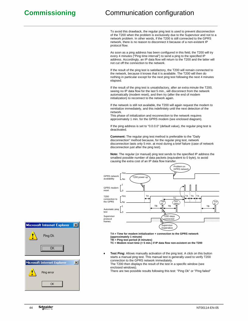
Commissioning Communication configuration
44 NT00114-EN-05
To avoid this drawback, the regular ping test is used to prevent disconnection of the T200 when the problem is exclusively due to the Supervisor and not to a network problem. In other words, if the T200 is still connected to the GPRS network, there is no reason to disconnect it because of a non-existent IP protocol flow. As soon as a ping address has been configured in this field, the T200 will try every 4 minutes (“Ping time interval”) to send a ping to the specified IP address. Accordingly, an IP data flow will return to the T200 and the latter will not cut off the connection to the network. If the result of the ping test is satisfactory, the T200 will remain connected to the network, because it knows that it is available. The T200 will then do nothing in particular except for the next ping test following the next 4 minutes elapsed. If the result of the ping test is unsatisfactory, after an extra minute the T200, seeing no IP data flow for the last 5 min., will disconnect from the network automatically (modem reset), and then try (after the end of modem initialization) to reconnect to the network again. If the network is still not available, the T200 will again request the modem to reinitialize immediately, and this indefinitely until the next detection of the network. This phase of initialization and reconnection to the network requires approximately 1 min. for the GPRS modem (see enclosed diagram). If the ping address is set to "0.0.0.0" (default value), the regular ping test is deactivated. Comment: The regular ping test method is preferable to the "Daily disconnection" method because, for the regular ping test, network disconnection lasts only 5 min. at most during a brief failure (case of network disconnection just after the ping test). Note: The regular (or manual) ping test sends to the specified IP address the smallest possible number of data packets (equivalent to 0 byte), to avoid causing the extra cost of an IP data flow transfer. TA = Time for modem initialization + connection to the GPRS network (approximately 1 minute) TB = Ping test period (4 minutes) TC = Modem reset time (= 5 min.) if IP data flow no n-existent on the T200
♦ Test Ping: Allows manually activation of the ping test. A click on this button starts a manual ping test. This manual test is generally used to verify T200 connection to the GPRS network immediately. The T200 then displays the result of the test in a specific window (see enclosed windows). There are two possible results following this test: "Ping Ok" or "Ping failed"
TA TA TA
Problem on GPRS network
T200 power up
1
0
Yes
No
Yes
No
1
0
GPRS network availability
GPRS modem reset
T200 connection to the GPRS
Automatic ping test
Supervisor protocol frames
TA
TB TB TB
TC
Test ok
Test ok
Test failed
Supervisor inoperative
T200 stays connected

Commissioning Communication configuration
NT00114-EN-05 45
08:48:34.474 MODEM - Power up 08:48:35.986 MODEM - Command mode 08:48:36.994 MODEM - Tx : ATE0 08:48:39.518 MODEM - Tx : AT&S0 08:48:42.045 MODEM - Tx : AT 08:48:43.071 MODEM - Rx : OK 08:48:44.079 MODEM - Tx : AT+CPIN? 08:48:45.120 MODEM - Rx : +CPIN: SIM PIN 08:48:45.120 MODEM - Tx : AT+CPIN=**** 08:48:47.230 MODEM - Rx : OK 08:48:47.230 MODEM - Tx : AT+CLCK="SC",0,**** 08:48:49.770 MODEM - Tx : AT+CREG? 08:48:50.807 MODEM - Rx : +CREG: 0,1 08:48:50.807 MODEM - Tx : AT+CSCA=0689004000 08:48:54.818 MODEM - Tx : AT+CMCF=1 08:48:57.347 MODEM - Tx : AT+CSAS 08:48:59.875 MODEM - Tx : AT+CMEE=0 08:49:02.403 MODEM - Tx : AT&C1 08:49:04.929 MODEM - Tx : AT&D2 08:49:07.455 MODEM - Tx : AT+IPR=0 08:49:09.983 MODEM - Tx : ATS0=1 08:49:12.509 MODEM - Tx : AT+WIND=0 08:49:15.039 MODEM - Tx : AT+CICB=0 08:49:17.567 MODEM - Tx : AT+CBST=7,0,1 08:49:20.101 MODEM - Tx : AT&W 08:49:32.706 MODEM - Tx : AT+CGCLASS? 08:49:33.720 MODEM - Rx : +CGCLASS: "B" 08:49:33.720 MODEM - Tx : AT+CGDCONT=1,"IP","internet-company" 08:49:36.248 MODEM - Tx : AT+CGATT=1 08:49:38.769 MODEM - Tx : AT+CGREG? 08:49:39.784 MODEM - Rx : +CGREG: 0,1 08:49:39.784 MODEM - Tx : AT+CGACT=1,1 08:49:42.307 MODEM - Tx : ATD*99***1# 08:49:43.327 MODEM - Connection 08:49:44.335 MODEM - PPP link: UP -> ESTABLISH () 08:49:44.350 MODEM - PPP link: OPEN -> AUTH () 08:49:44.363 MODEM - PPP link: PAP: Local successfully authenticated 08:49:44.363 MODEM - PPP link: SUCCESS -> NETWORK () 08:49:44.363 MODEM - PPP link: IPCP UP -> NETWORK () 08:49:44.400 MODEM - PPP link: IPCP CONFIGURED -> NETWORK () 08:49:44.401 MODEM - PPP link: connected, local=90.95.65.78 , dest=212.234.96.90 08:49:44.401 MODEM - GPRS modem initialized Example of port trace in the event of a connection to the GPRS network
♦ Ping time interval: Delay between two successive automatic “Test ping”. ♦ Ping attempts: Number of maximum attempts for the “Test ping” process in
case of no response from remote IP address. ♦ Ping time out: Maximum delay to wait for the response during the “Test ping”
to define “Ping error”. ♦ Authentication: When the GPRS network requires authentication during the
connection phase, it is possible in such cases to activate this function by checking the corresponding box. The authorized encryption protocols are: - PAP, CHAP, MSCHAP, MSCHAP V2
♦ Login: Configuration of the login used for authentication. Configure this field only if the "Authentication" option has been checked.
♦ Password: Configuration of the password used for authentication. Configure
this field only if the "Authentication" option has been checked.
Note: To check that the modem is correctly connected to the GPRS network, it is possible to consult the trace of the port corresponding to the GPRS modem. The modem starts by initializing the GSM connection and then the GPRS connection. Accordingly, following the AT commands for connection to the GSM network can be found the commands relating to GPRS connection. At the end of them, the trace should indicate "GPRS modem initialized" with also the indication of the IP addresses of the T200 assigned by the operator (local=xxx.xxx.xxx.xxx ) and the IP address of the GPRS gateway provider (dest=xxx.xxx.xxx.xxx ) (see example opposite). Modem connection status:
Same comment as for the GSM modem.
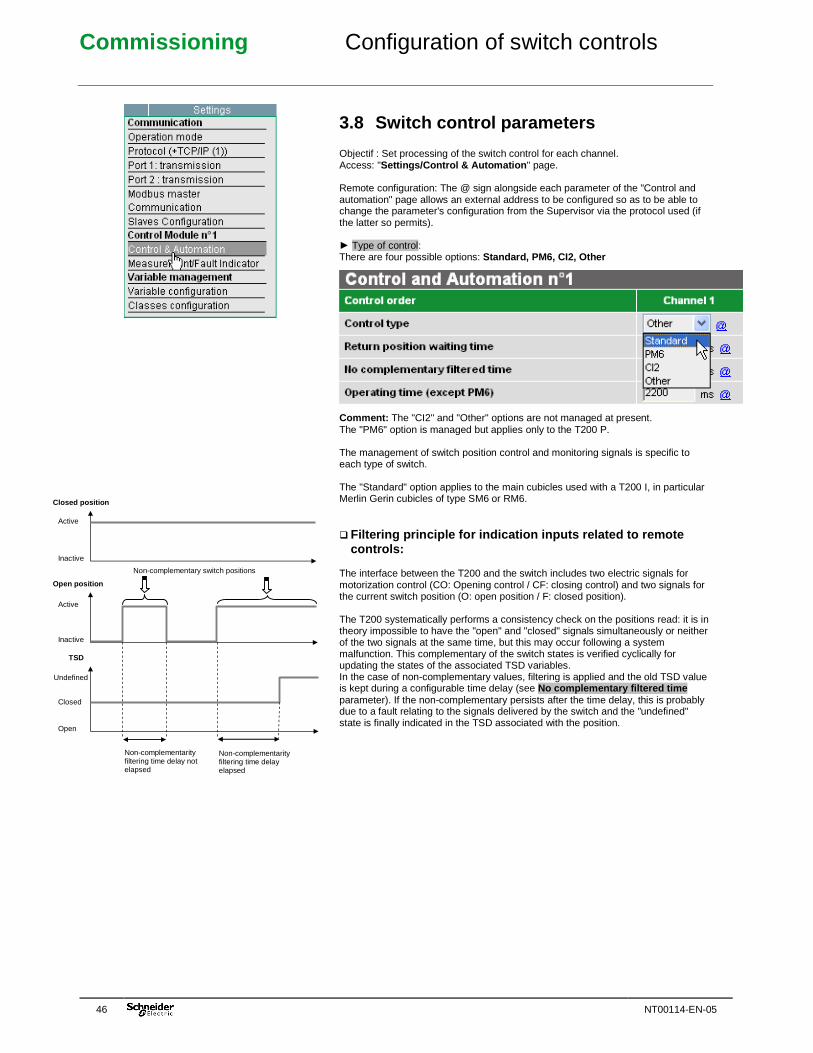
Commissioning Configuration of switch controls
46 NT00114-EN-05
3.8 Switch control parameters Objectif : Set processing of the switch control for each channel. Access: "Settings/Control & Automation " page. Remote configuration: The @ sign alongside each parameter of the "Control and automation" page allows an external address to be configured so as to be able to change the parameter's configuration from the Supervisor via the protocol used (if the latter so permits). ► Type of control: There are four possible options: Standard, PM6, CI2, Other Comment: The "CI2" and "Other" options are not managed at present. The "PM6" option is managed but applies only to the T200 P. The management of switch position control and monitoring signals is specific to each type of switch. The "Standard" option applies to the main cubicles used with a T200 I, in particular Merlin Gerin cubicles of type SM6 or RM6. � Filtering principle for indication inputs related t o remote
controls: The interface between the T200 and the switch includes two electric signals for motorization control (CO: Opening control / CF: closing control) and two signals for the current switch position (O: open position / F: closed position). The T200 systematically performs a consistency check on the positions read: it is in theory impossible to have the "open" and "closed" signals simultaneously or neither of the two signals at the same time, but this may occur following a system malfunction. This complementary of the switch states is verified cyclically for updating the states of the associated TSD variables. In the case of non-complementary values, filtering is applied and the old TSD value is kept during a configurable time delay (see No complementary filtered time parameter). If the non-complementary persists after the time delay, this is probably due to a fault relating to the signals delivered by the switch and the "undefined" state is finally indicated in the TSD associated with the position.
Active
Inactive
Closed position
Active
Inactive
Open position
Closed
Open
TSD
Non-complementarity filtering time delay not elapsed
Non-complementarity filtering time delay elapsed
Non-complementary switch positions
Undefined
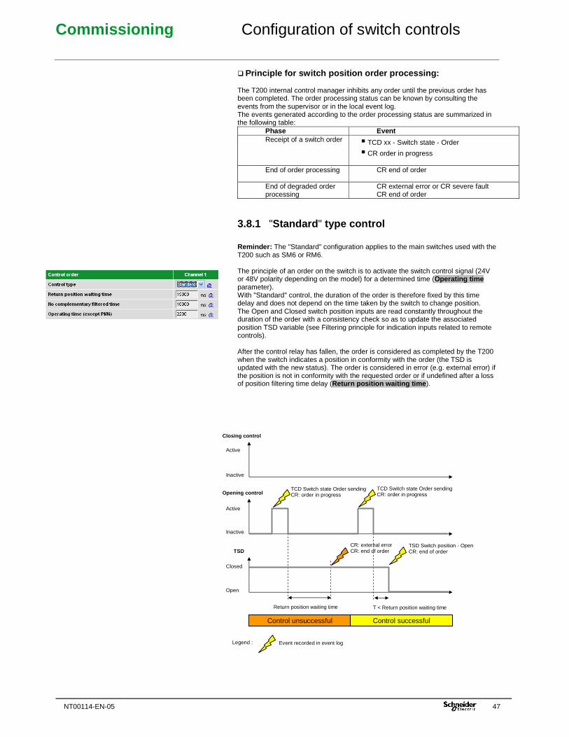
Commissioning Configuration of switch controls
NT00114-EN-05 47
� Principle for switch position order processing: The T200 internal control manager inhibits any order until the previous order has been completed. The order processing status can be known by consulting the events from the supervisor or in the local event log. The events generated according to the order processing status are summarized in the following table:
Phase Event Receipt of a switch order � TCD xx - Switch state - Order
� CR order in progress
End of order processing CR end of order
End of degraded order processing
CR external error or CR severe fault CR end of order
3.8.1 "Standard " type control Reminder: The "Standard" configuration applies to the main switches used with the T200 such as SM6 or RM6. The principle of an order on the switch is to activate the switch control signal (24V or 48V polarity depending on the model) for a determined time (Operating time parameter). With "Standard" control, the duration of the order is therefore fixed by this time delay and does not depend on the time taken by the switch to change position. The Open and Closed switch position inputs are read constantly throughout the duration of the order with a consistency check so as to update the associated position TSD variable (see Filtering principle for indication inputs related to remote controls). After the control relay has fallen, the order is considered as completed by the T200 when the switch indicates a position in conformity with the order (the TSD is updated with the new status). The order is considered in error (e.g. external error) if the position is not in conformity with the requested order or if undefined after a loss of position filtering time delay (Return position waiting time ).
Active
Inactive
Closing control
Active
Inactive
Opening control TCD Switch state Order sending CR: order in progress
TCD Switch state Order sending CR: order in progress
Closed
Open
TSD TSD Switch position - Open CR: end of order
CR: external error CR: end of order
Return position waiting time T < Return position waiting time
Event recorded in event log Legend :
Control unsuccessful Control successful
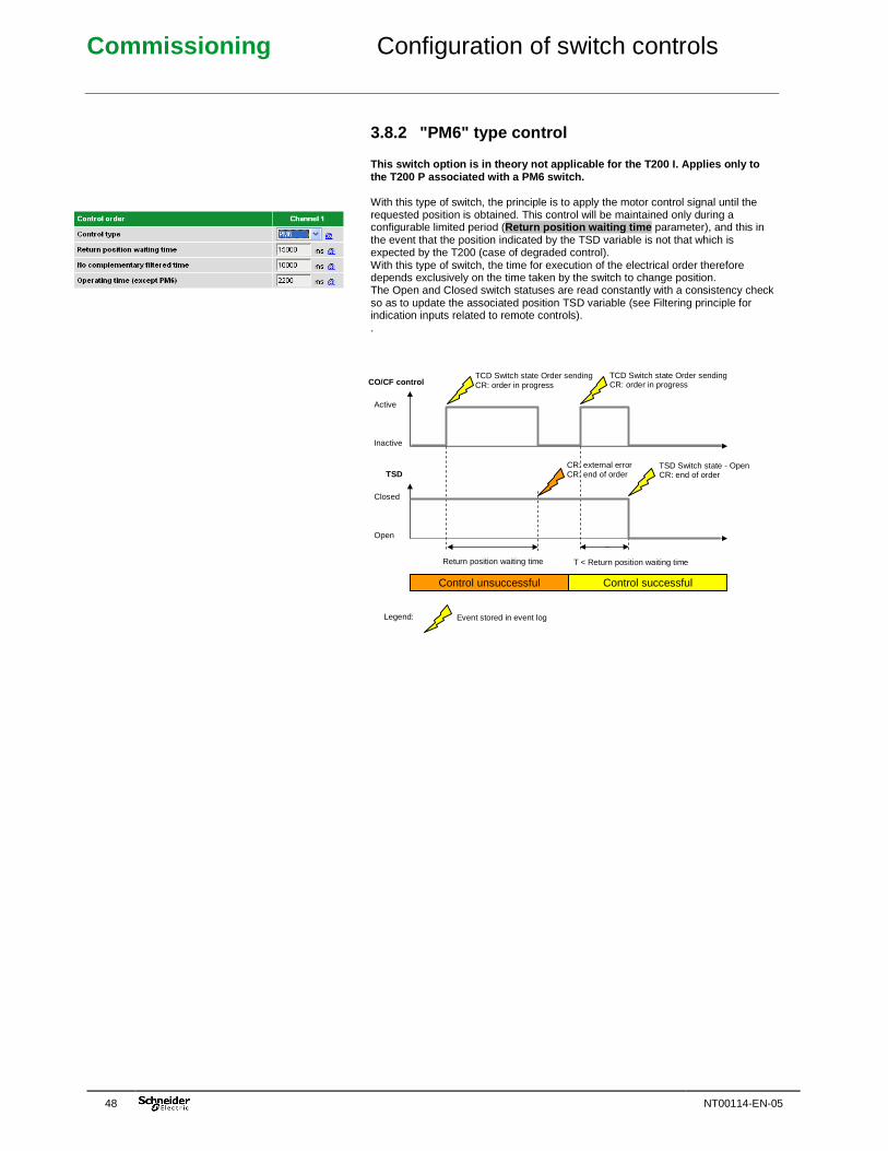
Commissioning Configuration of switch controls
48 NT00114-EN-05
3.8.2 "PM6" type control
This switch option is in theory not applicable for the T200 I. Applies only to the T200 P associated with a PM6 switch. With this type of switch, the principle is to apply the motor control signal until the requested position is obtained. This control will be maintained only during a configurable limited period (Return position waiting time parameter), and this in the event that the position indicated by the TSD variable is not that which is expected by the T200 (case of degraded control). With this type of switch, the time for execution of the electrical order therefore depends exclusively on the time taken by the switch to change position. The Open and Closed switch statuses are read constantly with a consistency check so as to update the associated position TSD variable (see Filtering principle for indication inputs related to remote controls). .
Active
Inactive
CO/CF control TCD Switch state Order sending CR: order in progress
TCD Switch state Order sending CR: order in progress
Closed
Open
TSD TSD Switch state - Open CR: end of order
CR: external error CR: end of order
Return position waiting time T < Return position waiting time
Event stored in event log Legend:
Control unsuccessful Control successful
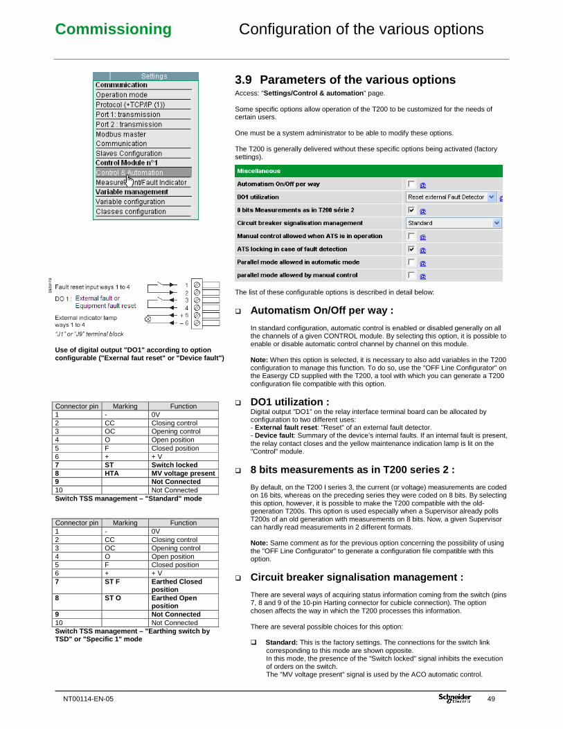
Commissioning Configuration of the various options
NT00114-EN-05 49
Use of digital output "DO1" according to option configurable ("Exernal faut reset" or "Device fault ") Connector pin Marking Function 1 - 0V 2 CC Closing control 3 OC Opening control 4 O Open position 5 F Closed position 6 + + V 7 ST Switch locked 8 HTA MV voltage present 9 Not Connected 10 Not Connected Switch TSS management – "Standard" mode Connector pin Marking Function 1 - 0V 2 CC Closing control 3 OC Opening control 4 O Open position 5 F Closed position 6 + + V 7 ST F Earthed Closed
position 8 ST O Earthed Open
position 9 Not Connected 10 Not Connected Switch TSS management – "Earthing switch by TSD" or "Specific 1" mode
3.9 Parameters of the various options Access: "Settings/Control & automation " page. Some specific options allow operation of the T200 to be customized for the needs of certain users. One must be a system administrator to be able to modify these options. The T200 is generally delivered without these specific options being activated (factory settings). The list of these configurable options is described in detail below:
� Automatism On/Off per way : In standard configuration, automatic control is enabled or disabled generally on all the channels of a given CONTROL module. By selecting this option, it is possible to enable or disable automatic control channel by channel on this module. Note: When this option is selected, it is necessary to also add variables in the T200 configuration to manage this function. To do so, use the "OFF Line Configurator" on the Easergy CD supplied with the T200, a tool with which you can generate a T200 configuration file compatible with this option.
� DO1 utilization : Digital output "DO1" on the relay interface terminal board can be allocated by configuration to two different uses: - External fault reset : "Reset" of an external fault detector. - Device fault : Summary of the device’s internal faults. If an internal fault is present, the relay contact closes and the yellow maintenance indication lamp is lit on the "Control" module.
� 8 bits measurements as in T200 series 2 : By default, on the T200 I series 3, the current (or voltage) measurements are coded on 16 bits, whereas on the preceding series they were coded on 8 bits. By selecting this option, however, it is possible to make the T200 compatible with the old-generation T200s. This option is used especially when a Supervisor already polls T200s of an old generation with measurements on 8 bits. Now, a given Supervisor can hardly read measurements in 2 different formats. Note: Same comment as for the previous option concerning the possibility of using the "OFF Line Configurator" to generate a configuration file compatible with this option.
� Circuit breaker signalisation management : There are several ways of acquiring status information coming from the switch (pins 7, 8 and 9 of the 10-pin Harting connector for cubicle connection). The option chosen affects the way in which the T200 processes this information. There are several possible choices for this option: � Standard: This is the factory settings. The connections for the switch link
corresponding to this mode are shown opposite. In this mode, the presence of the "Switch locked" signal inhibits the execution of orders on the switch. The "MV voltage present" signal is used by the ACO automatic control.
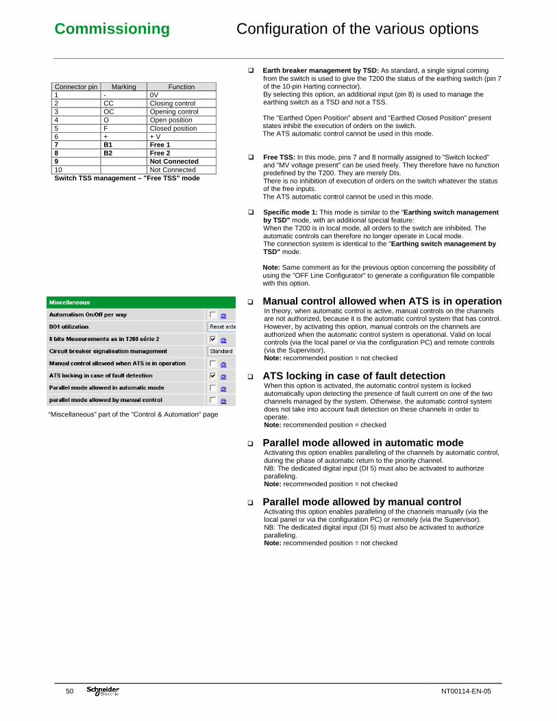
Commissioning Configuration of the various options
50 NT00114-EN-05
Connector pin Marking Function 1 - 0V 2 CC Closing control 3 OC Opening control 4 O Open position 5 F Closed position 6 + + V 7 B1 Free 1 8 B2 Free 2 9 Not Connected 10 Not Connected Switch TSS management – "Free TSS" mode
“Miscellaneous” part of the "Control & Automation" page
� Earth breaker management by TSD: As standard, a single signal coming
from the switch is used to give the T200 the status of the earthing switch (pin 7 of the 10-pin Harting connector). By selecting this option, an additional input (pin 8) is used to manage the earthing switch as a TSD and not a TSS. The "Earthed Open Position" absent and "Earthed Closed Position" present states inhibit the execution of orders on the switch. The ATS automatic control cannot be used in this mode.
� Free TSS: In this mode, pins 7 and 8 normally assigned to "Switch locked" and "MV voltage present" can be used freely. They therefore have no function predefined by the T200. They are merely DIs. There is no inhibition of execution of orders on the switch whatever the status of the free inputs. The ATS automatic control cannot be used in this mode.
� Specific mode 1: This mode is similar to the "Earthing switch management by TSD" mode, with an additional special feature: When the T200 is in local mode, all orders to the switch are inhibited. The automatic controls can therefore no longer operate in Local mode. The connection system is identical to the "Earthing switch management by TSD" mode. Note: Same comment as for the previous option concerning the possibility of using the "OFF Line Configurator" to generate a configuration file compatible with this option.
� Manual control allowed when ATS is in operation In theory, when automatic control is active, manual controls on the channels are not authorized, because it is the automatic control system that has control. However, by activating this option, manual controls on the channels are authorized when the automatic control system is operational. Valid on local controls (via the local panel or via the configuration PC) and remote controls (via the Supervisor). Note: recommended position = not checked
� ATS locking in case of fault detection When this option is activated, the automatic control system is locked automatically upon detecting the presence of fault current on one of the two channels managed by the system. Otherwise, the automatic control system does not take into account fault detection on these channels in order to operate. Note: recommended position = checked
� Parallel mode allowed in automatic mode Activating this option enables paralleling of the channels by automatic control, during the phase of automatic return to the priority channel. NB: The dedicated digital input (DI 5) must also be activated to authorize paralleling. Note: recommended position = not checked
� Parallel mode allowed by manual control Activating this option enables paralleling of the channels manually (via the local panel or via the configuration PC) or remotely (via the Supervisor). NB: The dedicated digital input (DI 5) must also be activated to authorize paralleling. Note: recommended position = not checked
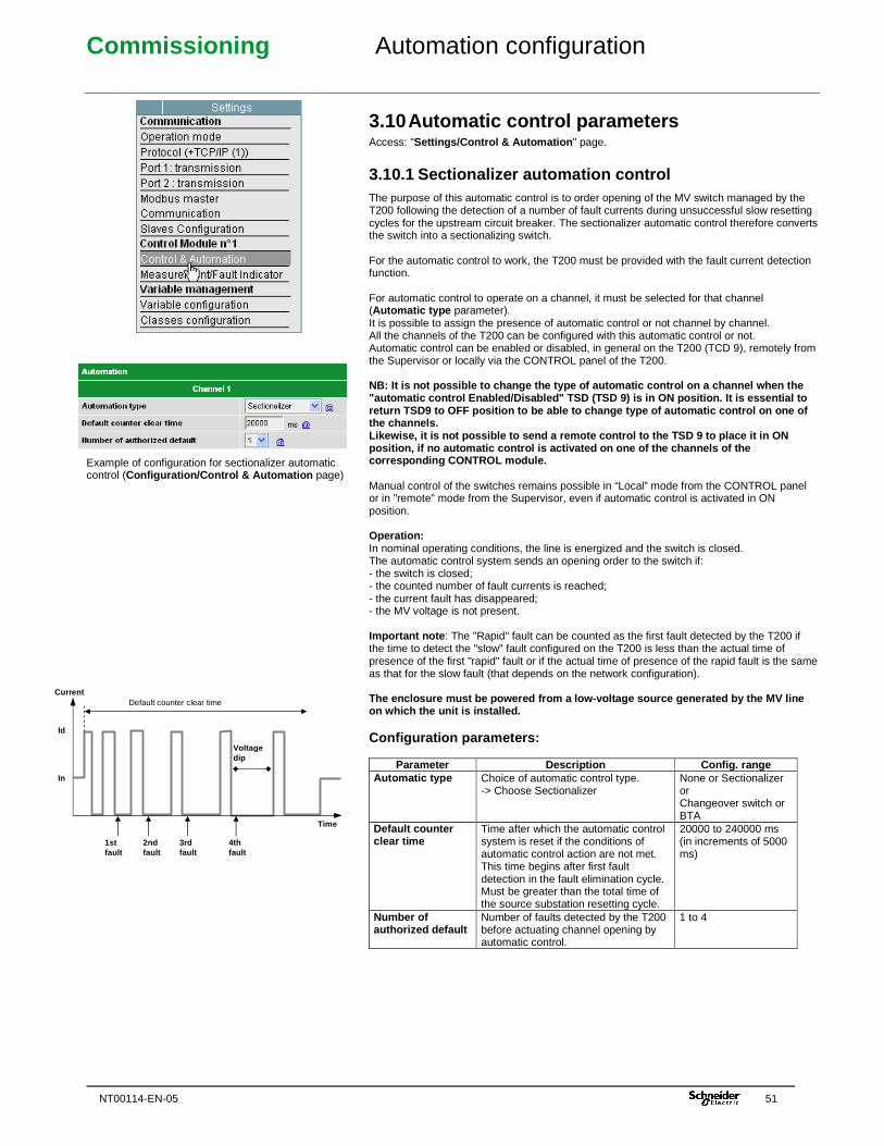
Commissioning Automation configuration
NT00114-EN-05 51
Example of configuration for sectionalizer automatic control (Configuration/Control & Automation page)
3.10 Automatic control parameters Access: "Settings/Control & Automation " page.
3.10.1 Sectionalizer automation control The purpose of this automatic control is to order opening of the MV switch managed by the T200 following the detection of a number of fault currents during unsuccessful slow resetting cycles for the upstream circuit breaker. The sectionalizer automatic control therefore converts the switch into a sectionalizing switch. For the automatic control to work, the T200 must be provided with the fault current detection function. For automatic control to operate on a channel, it must be selected for that channel (Automatic type parameter). It is possible to assign the presence of automatic control or not channel by channel. All the channels of the T200 can be configured with this automatic control or not. Automatic control can be enabled or disabled, in general on the T200 (TCD 9), remotely from the Supervisor or locally via the CONTROL panel of the T200. NB: It is not possible to change the type of automa tic control on a channel when the "automatic control Enabled/Disabled" TSD (TSD 9) is in ON position. It is essential to return TSD9 to OFF position to be able to change ty pe of automatic control on one of the channels. Likewise, it is not possible to send a remote contr ol to the TSD 9 to place it in ON position, if no automatic control is activated on o ne of the channels of the corresponding CONTROL module. Manual control of the switches remains possible in “Local” mode from the CONTROL panel or in "remote" mode from the Supervisor, even if automatic control is activated in ON position. Operation: In nominal operating conditions, the line is energized and the switch is closed. The automatic control system sends an opening order to the switch if: - the switch is closed; - the counted number of fault currents is reached; - the current fault has disappeared; - the MV voltage is not present. Important note : The "Rapid" fault can be counted as the first fault detected by the T200 if the time to detect the "slow" fault configured on the T200 is less than the actual time of presence of the first "rapid" fault or if the actual time of presence of the rapid fault is the same as that for the slow fault (that depends on the network configuration). The enclosure must be powered from a low-voltage so urce generated by the MV line on which the unit is installed. Configuration parameters:
Parameter Description Config. range Automatic type Choice of automatic control type.
-> Choose Sectionalizer None or Sectionalizer or Changeover switch or BTA
Default counter clear time
Time after which the automatic control system is reset if the conditions of automatic control action are not met. This time begins after first fault detection in the fault elimination cycle. Must be greater than the total time of the source substation resetting cycle.
20000 to 240000 ms (in increments of 5000 ms)
Number of authorized default
Number of faults detected by the T200 before actuating channel opening by automatic control.
1 to 4
Id
Current Default counter clear time
Voltage dip
Time
In
1st fault
2nd fault
3rd fault
4th fault
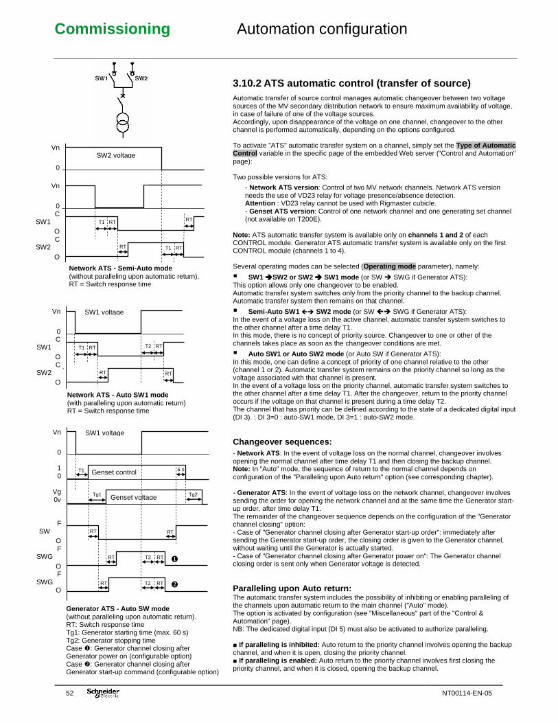
Commissioning Automation configuration
52 NT00114-EN-05
RT
3.10.2 ATS automatic control (transfer of source) Automatic transfer of source control manages automatic changeover between two voltage sources of the MV secondary distribution network to ensure maximum availability of voltage, in case of failure of one of the voltage sources. Accordingly, upon disappearance of the voltage on one channel, changeover to the other channel is performed automatically, depending on the options configured. To activate "ATS" automatic transfer system on a channel, simply set the Type of Automatic Control variable in the specific page of the embedded Web server ("Control and Automation" page): Two possible versions for ATS:
- Network ATS version : Control of two MV network channels. Network ATS version needs the use of VD23 relay for voltage presence/absence detection. Attention : VD23 relay cannot be used with Rigmaster cubicle. - Genset ATS version : Control of one network channel and one generating set channel (not available on T200E).
Note: ATS automatic transfer system is available only on channels 1 and 2 of each CONTROL module. Generator ATS automatic transfer system is available only on the first CONTROL module (channels 1 to 4). Several operating modes can be selected (Operating mode parameter), namely:
� SW1 ����SW2 or SW2 ���� SW1 mode (or SW � SWG if Generator ATS): This option allows only one changeover to be enabled. Automatic transfer system switches only from the priority channel to the backup channel. Automatic transfer system then remains on that channel.
� Semi-Auto SW1 � SW2 mode (or SW � SWG if Generator ATS): In the event of a voltage loss on the active channel, automatic transfer system switches to the other channel after a time delay T1. In this mode, there is no concept of priority source. Changeover to one or other of the channels takes place as soon as the changeover conditions are met.
� Auto SW1 or Auto SW2 mode (or Auto SW if Generator ATS): In this mode, one can define a concept of priority of one channel relative to the other (channel 1 or 2). Automatic transfer system remains on the priority channel so long as the voltage associated with that channel is present. In the event of a voltage loss on the priority channel, automatic transfer system switches to the other channel after a time delay T1. After the changeover, return to the priority channel occurs if the voltage on that channel is present during a time delay T2. The channel that has priority can be defined according to the state of a dedicated digital input (DI 3). : DI 3=0 : auto-SW1 mode, DI 3=1 : auto-SW2 mode. Changeover sequences: - Network ATS : In the event of voltage loss on the normal channel, changeover involves opening the normal channel after time delay T1 and then closing the backup channel. Note: In "Auto" mode, the sequence of return to the normal channel depends on configuration of the "Paralleling upon Auto return" option (see corresponding chapter). - Generator ATS : In the event of voltage loss on the network channel, changeover involves sending the order for opening the network channel and at the same time the Generator start-up order, after time delay T1. The remainder of the changeover sequence depends on the configuration of the "Generator channel closing" option: - Case of "Generator channel closing after Generator start-up order": immediately after sending the Generator start-up order, the closing order is given to the Generator channel, without waiting until the Generator is actually started. - Case of "Generator channel closing after Generator power on": The Generator channel closing order is sent only when Generator voltage is detected. Paralleling upon Auto return: The automatic transfer system includes the possibility of inhibiting or enabling paralleling of the channels upon automatic return to the main channel ("Auto" mode). The option is activated by configuration (see "Miscellaneous" part of the "Control & Automation" page). NB: The dedicated digital input (DI 5) must also be activated to authorize paralleling. ■ If paralleling is inhibited: Auto return to the priority channel involves opening the backup channel, and when it is open, closing the priority channel. ■ If paralleling is enabled: Auto return to the priority channel involves first closing the priority channel, and when it is closed, opening the backup channel.
Network A TS - Semi -Auto mode (without paralleling upon automatic return). RT = Switch response time
SW2 voltage Vn
0
Vn
0 C
SW1 O C
SW2 O
T1 RT
T1 RT
RT
RT
SW1 voltage Vn
0 C
SW1 O C
SW2 O
T1 RT T2 RT
RT RT
Network ATS - Auto SW1 mode (with paralleling upon automatic return) RT = Switch response time
Generator ATS - Auto SW mode (without paralleling upon automatic return). RT: Switch response time Tg1: Generator starting time (max. 60 s) Tg2: Generator stopping time Case �: Generator channel closing after Generator power on (configurable option) Case �: Generator channel closing after Generator start-up command (configurable option)
SW1 voltage Vn
0
1 0
Vg 0v
F SW
O F
SWG O F
SWG O
RT RT
RT RT
T1 Genset control
Tg1 Genset voltage
6 s
Tg2
T2
RT RT T2 �
�
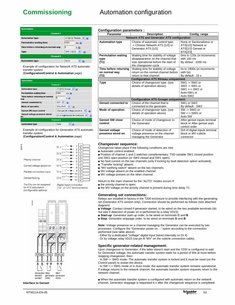
Commissioning Automation configuration
NT00114-EN-05 53
Example of configuration for Network ATS automatic transfer system (Configuration/Control & Automation page) Example of configuration for Generatior ATS automatic transfer system (Configuration/Control & Automation page) Interface to Genset
Configuration parameters :
Parameter Description Config. range Network ATS and Generator ATS configuration
Automation type Choice of automatic control type. -> Choose Network ATS [1/2] or Generator ATS [1/2]
None or Sectionalizeur or ATS[1/2] Network or ATS[1/2] Genset or BTA[2/3]
Permutation waiting type (T1)
Waiting time for stability of voltage disappearance on the channel that was operational before the start of the changeover cycle
0ms to 120s (in increments with 100 ms By defaut : 1000 ms
Time before returning on normal way (T2)
Waiting time for stability of voltage return on the normal channel before return to that channel
0s to 1800s (in increments with 5s) By default : 15 s
Configuration ATS Réseau uniquement Type Choice of changeover type. (see
details of operation above) SW1 -> SW2 or SW2 -> SW1 or SW1 <-> SW2 or Auto-SW1 or Auto-SW2
Configuration ATS Groupe uniquement Genset connected to Choice of the channel that is
connected to the generator SW1 or SW2 By default : SW2
Mode of operation Choice of changeover type. (see details of operation above)
SW -> SWG or SW <-> SWG or Auto SW
Genset SW close control
Choice of mode of changeover to the Generator
After genset inputs terminal block or After genset start control order
Genset voltage presence wired on
Choice of mode of detection of voltage presence on the channel managing the Generator
DI4 of digital inputs terminal block or MV cubicle connector
Changeover sequence: Changeover takes place if the following conditions are met: ■ Automatic control enabled. ■ Position of channel 1 and 2 switches complementary: TSD variable SW1 closed position and SW2 open position (or SW2 closed and SW1 open). ■ No fault current on the two channels (only if locking by fault detection option activated); ■ "Transfer locking" absent; ■ "MV earthing switch" absent on the two channels; ■ MV voltage absent on the enabled channel; ■ MV voltage present on the other channel. Return to the main channel for the “AUTO” modes occurs if: ■ the priority channel is open; ■ the MV voltage on the priority channel is present during time delay T2. Generating set connections: Relays are installed in factory in the T200 enclosure to provide interfacing with the generating set (Generator ATS version only). Connection should be performed as follows (see attached diagram): ■ Voltage : Contact closed if generator started, to be wired on the two available terminals (do not wire if detection of power on is performed by a relay VD23) ■ Start-up : Generator start-up order, to be wired on terminals C and B ■ Stop : Generator stoppage order, to be wired on terminals D and B Note: Voltage presence on a channel managing the Generator can be executed by two processes. Configure the "Generator power on…" option according to the connection performed (see table above): - Either by a dedicated "Voltage" digital input (wired internally on DI 4) - Or by voltage relay VD23 (via pin 8-"MV" on the cubicle connection cable). Specific generator-related management: Upon changeover to Generator, if the latter doesn't start and the T200 is configured to wait for Generator voltage, the automatic transfer system waits for a period of 60s at most before stopping changeover, then: - In SW -> SWG mode: The automatic transfer system is locked and it must be reset (on the Control panel) to restart the device. - In SW <-> SWG mode or in Auto mode: the automatic transfer system remains operational. If voltage returns to the network channel, the automatic transfer system requests return to the network channel. ■ When the automatic transfer system is configured with automatic return on the network channel, Generator stoppage is requested 6 s after the changeover sequence is completed.
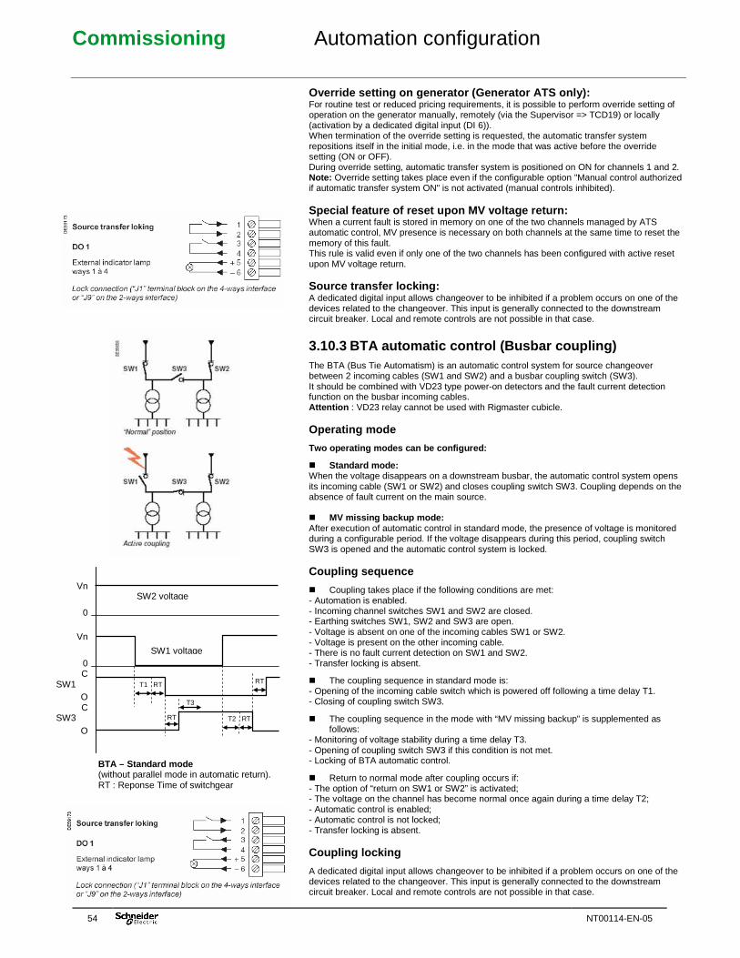
Commissioning Automation configuration
54 NT00114-EN-05
Override setting on generator (Generator ATS only): For routine test or reduced pricing requirements, it is possible to perform override setting of operation on the generator manually, remotely (via the Supervisor => TCD19) or locally (activation by a dedicated digital input (DI 6)). When termination of the override setting is requested, the automatic transfer system repositions itself in the initial mode, i.e. in the mode that was active before the override setting (ON or OFF). During override setting, automatic transfer system is positioned on ON for channels 1 and 2. Note: Override setting takes place even if the configurable option "Manual control authorized if automatic transfer system ON" is not activated (manual controls inhibited). Special feature of reset upon MV voltage return: When a current fault is stored in memory on one of the two channels managed by ATS automatic control, MV presence is necessary on both channels at the same time to reset the memory of this fault. This rule is valid even if only one of the two channels has been configured with active reset upon MV voltage return. Source transfer locking: A dedicated digital input allows changeover to be inhibited if a problem occurs on one of the devices related to the changeover. This input is generally connected to the downstream circuit breaker. Local and remote controls are not possible in that case.
3.10.3 BTA automatic control (Busbar coupling) The BTA (Bus Tie Automatism) is an automatic control system for source changeover between 2 incoming cables (SW1 and SW2) and a busbar coupling switch (SW3). It should be combined with VD23 type power-on detectors and the fault current detection function on the busbar incoming cables. Attention : VD23 relay cannot be used with Rigmaster cubicle. Operating mode
Two operating modes can be configured:
� Standard mode: When the voltage disappears on a downstream busbar, the automatic control system opens its incoming cable (SW1 or SW2) and closes coupling switch SW3. Coupling depends on the absence of fault current on the main source. � MV missing backup mode: After execution of automatic control in standard mode, the presence of voltage is monitored during a configurable period. If the voltage disappears during this period, coupling switch SW3 is opened and the automatic control system is locked. Coupling sequence
� Coupling takes place if the following conditions are met: - Automation is enabled. - Incoming channel switches SW1 and SW2 are closed. - Earthing switches SW1, SW2 and SW3 are open. - Voltage is absent on one of the incoming cables SW1 or SW2. - Voltage is present on the other incoming cable. - There is no fault current detection on SW1 and SW2. - Transfer locking is absent.
� The coupling sequence in standard mode is: - Opening of the incoming cable switch which is powered off following a time delay T1. - Closing of coupling switch SW3.
� The coupling sequence in the mode with “MV missing backup” is supplemented as follows:
- Monitoring of voltage stability during a time delay T3. - Opening of coupling switch SW3 if this condition is not met. - Locking of BTA automatic control.
� Return to normal mode after coupling occurs if: - The option of “return on SW1 or SW2” is activated; - The voltage on the channel has become normal once again during a time delay T2; - Automatic control is enabled; - Automatic control is not locked; - Transfer locking is absent. Coupling locking
A dedicated digital input allows changeover to be inhibited if a problem occurs on one of the devices related to the changeover. This input is generally connected to the downstream circuit breaker. Local and remote controls are not possible in that case.
SW1 voltage
SW2 voltage Vn
0
Vn
0 C
SW1 O C
SW3 O
T1 RT
T2 RT
RT
RT
T3
BTA – Standard mode (without parallel mode in automatic return). RT : Reponse Time of switchgear
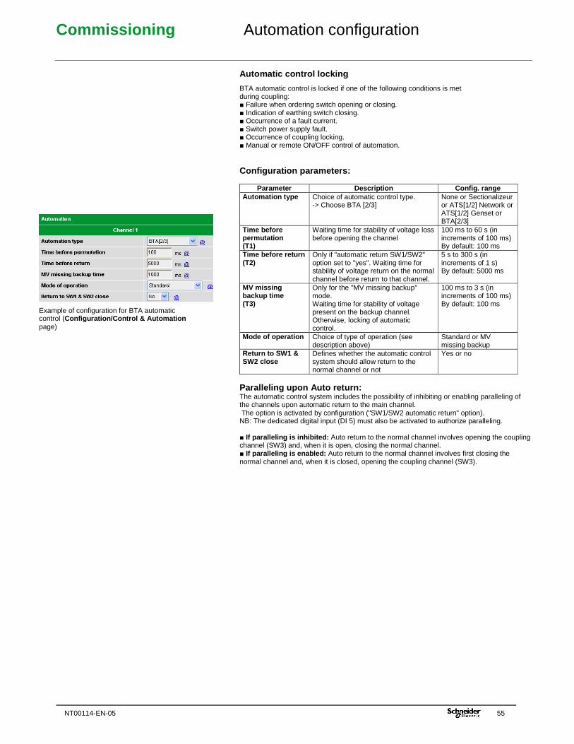
Commissioning Automation configuration
NT00114-EN-05 55
Automatic control locking
BTA automatic control is locked if one of the following conditions is met during coupling: ■ Failure when ordering switch opening or closing. ■ Indication of earthing switch closing. ■ Occurrence of a fault current. ■ Switch power supply fault. ■ Occurrence of coupling locking. ■ Manual or remote ON/OFF control of automation. Configuration parameters:
Parameter Description Config. range Automation type Choice of automatic control type.
-> Choose BTA [2/3] None or Sectionalizeur or ATS[1/2] Network or ATS[1/2] Genset or BTA[2/3]
Time before permutation (T1)
Waiting time for stability of voltage loss before opening the channel
100 ms to 60 s (in increments of 100 ms) By default: 100 ms
Time before return (T2)
Only if "automatic return SW1/SW2" option set to "yes". Waiting time for stability of voltage return on the normal channel before return to that channel.
5 s to 300 s (in increments of 1 s) By default: 5000 ms
MV missing backup time (T3)
Only for the "MV missing backup" mode. Waiting time for stability of voltage present on the backup channel. Otherwise, locking of automatic control.
100 ms to 3 s (in increments of 100 ms) By default: 100 ms
Mode of operation Choice of type of operation (see description above)
Standard or MV missing backup
Return to SW1 & SW2 close
Defines whether the automatic control system should allow return to the normal channel or not
Yes or no
Paralleling upon Auto return: The automatic control system includes the possibility of inhibiting or enabling paralleling of the channels upon automatic return to the main channel. The option is activated by configuration ("SW1/SW2 automatic return" option). NB: The dedicated digital input (DI 5) must also be activated to authorize paralleling. ■ If paralleling is inhibited: Auto return to the normal channel involves opening the coupling channel (SW3) and, when it is open, closing the normal channel. ■ If paralleling is enabled: Auto return to the normal channel involves first closing the normal channel and, when it is closed, opening the coupling channel (SW3).
Example of configuration for BTA automatic control (Configuration/Control & Automation page)
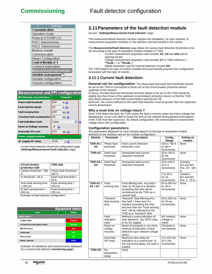
Commissioning Fault detector configuration
56 NT00114-EN-05
Current fault detection threshold configuration page (Settings/Measurement-Fault indicator page) Circuit breaker protection side
T200 side
I phase threshold = 350 A
Phase fault threshold = 330 A
I0 threshold = 45 A Earth fault threshold = 40 A
Imax fault sensing time = 250 ms
Fault sensing time = 225 ms
I0 fault sensing time = 250 ms
Fault sensing time = 225 ms
Example of fault detector configuration Example of indications and measurements displayed for a current fault detector (monitoring page )
3.11 Parameters of the fault detection module Access: "Settings/Measurement-Fault Indicator " page. The measurement/fault detection function requires the installation, for each channel, of measurement acquisition modules on the interface card and toroids in the cubicle. The Measurements/Fault detector page allows the various fault detection thresholds to be set according to the type of acquisition module installed on T200:
- Current measurement acquisition card (models AC, AS and AH) and its opening toroids
- Voltage measurement acquisition card (models AT or T200 reference = "TIxxB-.." or "TExxB-.."
- Digital acquisition card for external detectors (model AD). The T200 detects the type of module installed and automatically proposes the configuration associated with that type of module.
3.11.1 Current fault detection:
General rule for configuration: The phase fault and earth fault thresholds should be set on the T200 to correspond to those set on the circuit breaker protection device upstream of the network. In theory, the fault detection thresholds and time delays to be set on the T200 should be slightly less than those of the upstream circuit breaker protection device so that the T200 may detect presence of the fault current before opening the CB. Moreover, the current defined for the earth fault detection must be greater than the capacitive current downstream.
Why a reset time on voltage return ? Once T200 detect the fault, the T200 stores the fault in memory when the mains voltage has disappeared, so as to be able to locate the fault on the network during general interrogation of the T200 from the Supervisor. By default configuration, this memorization is erased when voltage return ON (configurable).
Configuration parameters: The parameters displayed for each channel depend on the type of acquisition module detected on the interface and on the module configuration:
Module Parameter Description Config. Range
Setting on module
T200-AC / AS
Phase fault threshold
Fault current detection threshold I max
100 to 750 A (in 50 A increments)
None
T200-AC Earth fault threshold
Homopolar fault current detection threshold
20 to 160 A (in 5A increments)
None
20 to 160 A (in 5 A increments)
Jumpers W1 and W2: Pos. 20 - 160 A
T200-AS / AH
Earth fault threshold
Homopolar fault current detection threshold
2 to 25 A (in 1A increments)
Jumpers W1 and W2: Pos. 2 - 25 A
Fault sensing time
Fault filtering time. Any fault > Imax (or I0) and of a duration exceeding this time will be considered by the T200 as a current fault.
50 to 500 ms (in 25 A increments)
None
Transient fault sensing time
"transient" fault filtering time. Any fault > Imax and of a duration exceeding this time and less than the "Fault sensing time" will be indicated by the T200 as a "transient" fault
50 to 200 ms (in 25 ms increments)
None
Fault indication reset
Method to erase indication of fault detection : (by VD23 relay or by AC supply)
MV network voltage or mains
None
Reset on voltage recovery
Reset (if selected) or not of the memory of indication of fault detection upon network voltage return.
Checked or not checked
None
T200-AC / AS / AH
Automatic FPI reset
Maximum time delay for indication of a current fault. At the end of this delay, the fault is erased.
0 to 120 min. (in 5 min. increments)
None
T200-AD No parameters setup
None
Commissioning Fault detector configuration
NT00114-EN-05 57
Voltage fault detection threshold configuration page (Configuration/Measurements-Fault indicator page)
Note: (*) The rated voltage to be configured corresponds in theory to a line-to-neutral voltage of 63.5 V (110 V/√3) on entering the voltage acquisition card. If this is not the ca se (e.g. 100 V/√3), the rated voltage to be configured will have to mu ltiplied by the following ratio: 110 / line-to-line input voltage (e.g. for an input voltage of 100 V/√3 and a rated voltage of 20000 V, configure 20000 * 110/100 = 22000 V).
Example of indications and measurements displayed for voltage fault detection (monitoring page )
Voltage fault detection: The following parameters should be configured on the T200 for the mains voltage monitoring function to operate:
Module Parameter Description Config. range Nominal voltage Real rated voltage (line-to-line) of the
network to be configured (*) 50 to 30000 V
AC supply OFF Network rated voltage threshold (as a percentage) below which the T200 detects network power off
20% to 95%
T200-AT or T200
reference = "TIxxB -
.." or "TExxB -.." Residual voltage Voltage variation of a phase (as a
percentage) relative to the other phases for residual voltage fault indication
5% to 50%
When the above threshold percentage conditions are exceeded, the T200 generates indications in the form of TSS for which the correspondence with the internal variables of the T200 for each channel is given in the table below: � Correspondence of internal variables of the T200 de pending on
the type of fault detection:
Current fault detection variables Voltage fault det ection variables
T200 channel
Phase fault
Earth fault or homop. fault A (*)
Homop. fault (*) B
Phase current
Voltage absence
Residual voltage
Voltage
Chnl 1 TSS 77 TSS 71 TSS 72 TM2 TSS 77 TSS 71 TM2 Chnl 2 TSS 109 TSS 103 TSS 104 TM9 TSS 109 TSS 103 TM9 Chnl 3 TSS 141 TSS 135 TSS 136 TM17 TSS 141 TSS 135 TM17 Chnl 4 TSS 173 TSS 167 TSS 168 TM24 TSS 173 TSS 167 TM24 Chnl 5 TSS 349 TSS 343 TSS 344 TM84 TSS 349 TSS 343 TM84 Chnl 6 TSS 381 TSS 375 TSS 376 TM91 TSS 381 TSS 375 TM91 Chnl 7 TSS 413 TSS 407 TSS 408 TM99 TSS 413 TSS 407 TM99 Chnl 8 TSS 445 TSS 439 TSS 440 TM106 TSS 445 TSS 439 TM106 Chnl 9 TSS 621 TSS 615 TSS 616 TM166 TSS 621 TSS 615 TM166 Chnl 10 TSS 653 TSS 647 TSS 648 TM173 TSS 653 TSS 647 TM173 Chnl 11 TSS 685 TSS 679 TSS 680 TM181 TSS 685 TSS 679 TM181 Chnl 12 TSS 717 TSS 711 TSS 712 TM188 TSS 717 TSS 711 TM188 Chnl 13 TSS 893 TSS 887 TSS 888 TM248 TSS 893 TSS 887 TM248 Chnl 14 TSS 925 TSS 919 TSS 920 TM255 TSS 925 TSS 919 TM255 Chnl 15 TSS 957 TSS 951 TSS 952 TM263 TSS 957 TSS 951 TM263 Chnl 16 TSS 989 TSS 983 TSS 984 TM266 TSS 989 TSS 983 TM266
Note: (*) = only for TSS card 3 (T200-AD). � Conversion of current measurements to voltage:
By default, the T200 is designed to operate for current measurements. However, it is possible to configure voltage measurements in place of current measurements on one or more channels of the equipment. Note that the two types of measurement (current and voltage) are not possible simultaneously on a given channel. The current to voltage conversion operation requires configuring certain variables of the T200. The procedure below explains how to carry out this conversion on a channel of the T200. The operation of course impacts the related measurement and fault detection. Note: With a single phase option measurement, voltage measurement is configured in factory on the latest channel of the equipment (factory standard). Note: The maximum voltage that can be displayed in the monitoring page is 32767 V, even if the real network voltage exceeds this value. � Procedure for conversion of current to voltage:
This procedure should be performed on all the channels on which the voltage measurement is present. Of course, the voltage acquisition module must be installed on the relay interface of the T200 in place of the current module:
- Log on to the T200 Web server as system administrator (user name: "Easergy" and password: "Easergy").
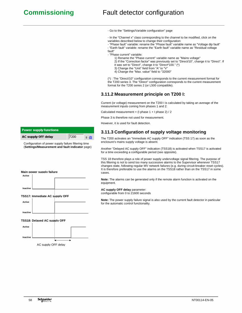
Commissioning Fault detector configuration
58 NT00114-EN-05
Configuration of power supply failure filtering time (Settings/Measurement and fault indicator page)
- Go to the "Settings/Variable configuration" page - In the "Channel x" class corresponding to the channel to be modified, click on the variables described below to change their configuration: - "Phase fault" variable: rename the "Phase fault" variable name as "Voltage dip fault" - "Earth fault" variable: rename the "Earth fault" variable name as "Residual voltage fault" - "Phase current" variable:
1) Rename the "Phase current" variable name as "Mains voltage" 2) If the "Correction factor" was previously set to "Direct/10", change it to "Direct". If it was set to "Direct", change it to "Direct*100." (*) 3) Change the "Unit" field from "A" to "V" 4) Change the "Max. value" field to "32000"
(*) : The "Direct/10" configuration corresponds to the current measurement format for the T200 series 3. The "Direct" configuration corresponds to the current measurement format for the T200 series 2 (or L500 compatible).
3.11.2 Measurement principle on T200 I:
Current (or voltage) measurement on the T200 I is calculated by taking an average of the measurement inputs coming from phases 1 and 2:
Calculated measurement = (I phase 1 + I phase 2) / 2
Phase 3 is therefore not used for measurement.
However, it is used for fault detection.
3.11.3 Configuration of supply voltage monitoring The T200 activates an "Immediate AC supply OFF" indication (TSS 17) as soon as the enclosure's mains supply voltage is absent. Another "Delayed AC supply OFF" indication (TSS18) is activated when TSS17 is activated for a time exceeding a configurable period (see opposite). TSS 18 therefore plays a role of power supply undervoltage signal filtering. The purpose of this filtering is not to send too many successive alarms to the Supervisor whenever TSS17 changes state, following regular MV network failures (e.g. during circuit-breaker reset cycles). It is therefore preferable to use the alarms on the TSS18 rather than on the TSS17 in some cases. Note: The alarms can be generated only if the remote alarm function is activated on the equipment. AC supply OFF delay parameter: configurable from 0 to 21600 seconds Note: The power supply failure signal is also used by the current fault detector in particular for the automatic control functionality.
Active
Inactive
Main power supply failure
Active
Inactive
TSS17: Immediate AC supply OFF
Active
Inactive
AC supply OFF delay
TSS18: Delayed AC supply OFF
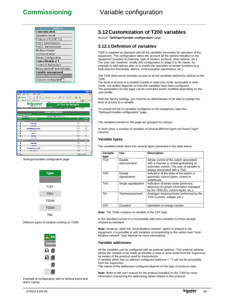
Commissioning Variable configuration
NT00114-EN-05 59
Settings/Variable configuration page Different types of variable existing on T200I Example of configuration with or without event and alarm saving
3.12 Customization of T200 variables Access: "Settings/Variable configuration " page.
3.12.1 Definition of variables T200 is supplied as standard with all the variables necessary for operation of the equipment. This configuration takes into account all the options installed on the equipment (number of channels, type of modem, protocol, other options, etc.). The user can, however, modify this configuration to adapt it to his needs, for example to add options later or to modify the operation of certain functions (e.g. fault detector thresholds, alarms, communication parameters, etc.). The T200 Web server provides access to all the variables defined by default on the T200. The level of access to a variable (visible in read-only mode, accessible in write mode, not visible) depends on how the variables have been configured. The parameters for this page can be consulted and/or modified depending on the user profile. With the factory settings, you must be an administrator to be able to change the level of access to a variable. To consult the list of variables configured on the equipment, open the "Settings/Variable configuration" page. The variables present in this page are grouped by classes. In each class, a number of variables of several different types are found ("type" column). Variable types : The variables break down into several types presented in the table below.
Variable type
Use Description
TCD Double telecommand
Allows control of the switch associated with a channel or enabling/disabling of automatic control. This type of variable is always associated with a TSD.
TSD Double signalisation
Indication of the state of the switch or automatic control (open, closed or undefined).
TSS Single signalisation Indication of binary state (presence, absence) of certain information managed by the T200 (DI, current faults, etc.).
TM Telemeasurement Analogue measurements performed by the T200 (current, voltage, etc.).
CNT Counters Operation or energy counter. Note: The T200I contains no variable of the CNT type. In the standard version it is not possible add extra variables to those already created as standard. Note: However, when the "local Modbus network" option is present in the equipment, it is possible to add variables corresponding to this option (see "local Modbus network" User Manual for more information). Variable addresses : All the variables can be configured with an external address. This external address allows the variable to be made accessible in read or write mode from the Supervisor by means of the protocol used for transmission. A variable which has no address configured (address = "-") will not be accessible from the Supervisor. The values of the addresses configured depend on the type of protocol used. Note : Refer to the user manual for the protocol installed on the T200 for more information concerning the addressing tables related to this protocol.
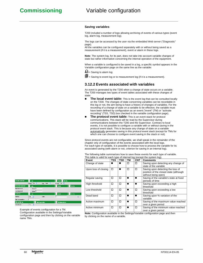
Commissioning Variable configuration
60 NT00114-EN-05
Example of events configuration for a TM. Configuration available in the Settings/Variable configuration page and then by clicking on the variable name TMx.
Saving variables : T200 included a number of logs allowing archiving of events of various types (event log, alarm log, measurement log). The logs can be accessed by the user via the embedded Web server ("Diagnostic" page). All the variables can be configured separately with or without being saved as a measurement (if it is a measurement), event or alarm in these logs. Note : The system log, for its part, does not take into account variable changes of state but rather information concerning the internal operation of the equipment. When a variable is configured to be saved in a log, a specific symbol appears in the Variable configuration page on the same line as the variable:
= Saving to alarm log
= Saving to event log or to measurement log (if it is a measurement).
3.12.2 Events associated with variables An event is generated by the T200 when a change of state occurs on a variable. The T200 manages two types of event tables associated with these changes of state: � The local event table: This is the event log that can be consulted locally
on the T200. The changes of state concerning variables can be recordable in this log or not, the aim being to have a history of changes of variables. For the recording of a change of state on a variable to be effective, the variable must have been defined by configuration as an event ("event" (TM) or "activate recording" (TSS, TSD) box checked in the variable configuration page).
� The protocol event table: This is an event stack for protocol communications. This stack will be read by the Supervisor during communications between the T200 and the Supervisor. Contrary to local events, it is not possible to configure a variable with or without saving in the protocol event stack. This is because any change of state on a variable automatically generates saving in this protocol event stack (except for TMs for which one can choose to configure event saving in the stack or not).
Since protocol events are not configurable, we shall speak in the remainder of the chapter only of configuration of the events associated with the local logs. For each type of variable, it is possible to choose how to process the variable for its associated saving (with alarm or not, criterion for saving in an internal log). The following table summarizes how to save these events for each type of variable. This table is valid for each type of internal log (except the system log). Event TSS TSD TM CNT Comments Change of state � � � � Saving upon detecting any change of
state of the variable Upon loss of closing � � � � Saving upon detecting the loss of
position of the closed state (although without being open)
Regular saving � � � � Saving of the variable's state at fixed periods of time
High threshold � � � � Saving upon exceeding a high threshold
Low threshold � � � � Saving upon exceeding a low threshold
Dead band � � � � Saving upon % variation of the variable
Active maximum � � � � Saving of the maximum value reached over a given period
Active minimum � � � � Saving of the minimum value reached over a given period
Note: Configuration available in the Settings/Variable configuration page and then by clicking on the name of a variable.
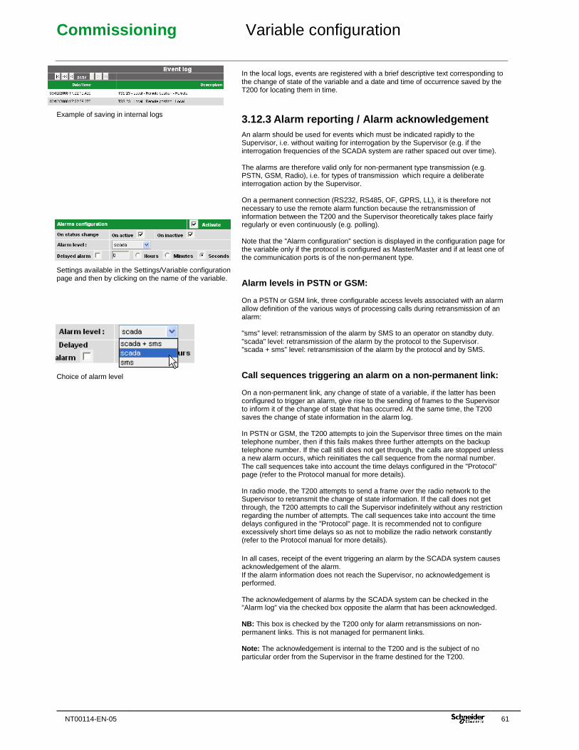
Commissioning Variable configuration
NT00114-EN-05 61
Example of saving in internal logs Settings available in the Settings/Variable configuration page and then by clicking on the name of the variable. Choice of alarm level
In the local logs, events are registered with a brief descriptive text corresponding to the change of state of the variable and a date and time of occurrence saved by the T200 for locating them in time.
3.12.3 Alarm reporting / Alarm acknowledgement An alarm should be used for events which must be indicated rapidly to the Supervisor, i.e. without waiting for interrogation by the Supervisor (e.g. if the interrogation frequencies of the SCADA system are rather spaced out over time). The alarms are therefore valid only for non-permanent type transmission (e.g. PSTN, GSM, Radio), i.e. for types of transmission which require a deliberate interrogation action by the Supervisor. On a permanent connection (RS232, RS485, OF, GPRS, LL), it is therefore not necessary to use the remote alarm function because the retransmission of information between the T200 and the Supervisor theoretically takes place fairly regularly or even continuously (e.g. polling). Note that the "Alarm configuration" section is displayed in the configuration page for the variable only if the protocol is configured as Master/Master and if at least one of the communication ports is of the non-permanent type. Alarm levels in PSTN or GSM: On a PSTN or GSM link, three configurable access levels associated with an alarm allow definition of the various ways of processing calls during retransmission of an alarm: "sms" level: retransmission of the alarm by SMS to an operator on standby duty. "scada" level: retransmission of the alarm by the protocol to the Supervisor. "scada + sms" level: retransmission of the alarm by the protocol and by SMS. Call sequences triggering an alarm on a non-permane nt link: On a non-permanent link, any change of state of a variable, if the latter has been configured to trigger an alarm, give rise to the sending of frames to the Supervisor to inform it of the change of state that has occurred. At the same time, the T200 saves the change of state information in the alarm log. In PSTN or GSM, the T200 attempts to join the Supervisor three times on the main telephone number, then if this fails makes three further attempts on the backup telephone number. If the call still does not get through, the calls are stopped unless a new alarm occurs, which reinitiates the call sequence from the normal number. The call sequences take into account the time delays configured in the "Protocol" page (refer to the Protocol manual for more details). In radio mode, the T200 attempts to send a frame over the radio network to the Supervisor to retransmit the change of state information. If the call does not get through, the T200 attempts to call the Supervisor indefinitely without any restriction regarding the number of attempts. The call sequences take into account the time delays configured in the "Protocol" page. It is recommended not to configure excessively short time delays so as not to mobilize the radio network constantly (refer to the Protocol manual for more details). In all cases, receipt of the event triggering an alarm by the SCADA system causes acknowledgement of the alarm. If the alarm information does not reach the Supervisor, no acknowledgement is performed. The acknowledgement of alarms by the SCADA system can be checked in the "Alarm log" via the checked box opposite the alarm that has been acknowledged. NB: This box is checked by the T200 only for alarm retransmissions on non-permanent links. This is not managed for permanent links. Note: The acknowledgement is internal to the T200 and is the subject of no particular order from the Supervisor in the frame destined for the T200.
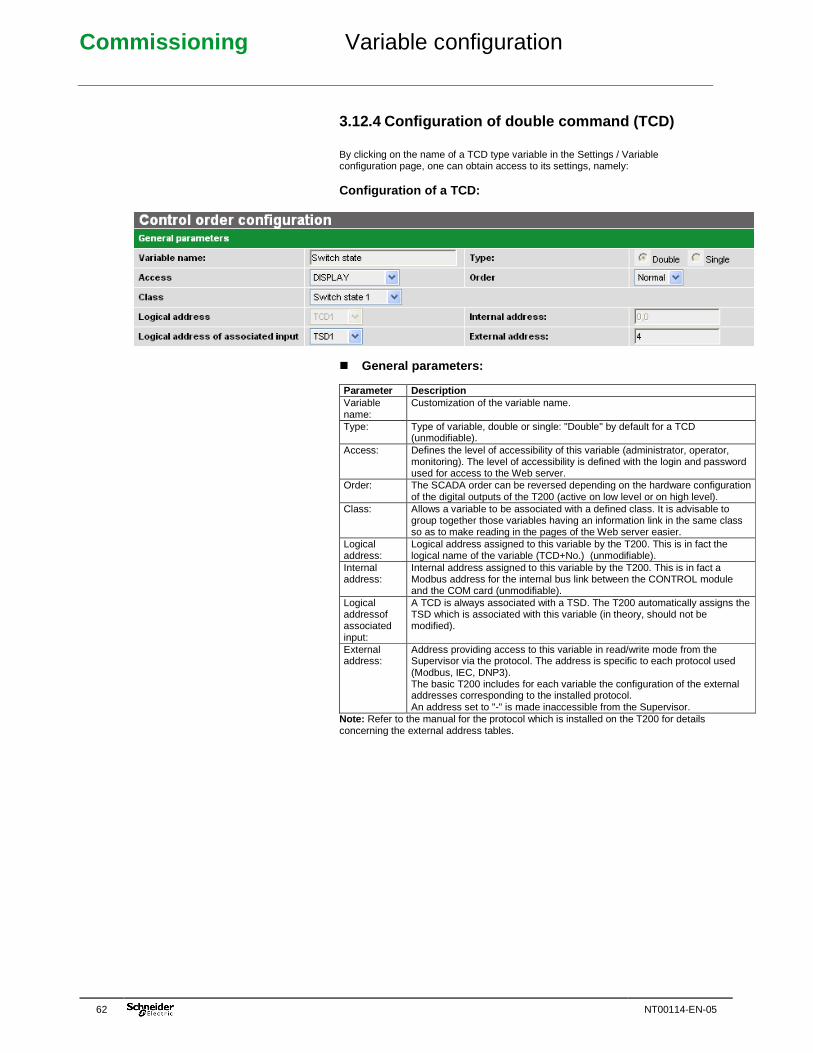
Commissioning Variable configuration
62 NT00114-EN-05
3.12.4 Configuration of double command (TCD) By clicking on the name of a TCD type variable in the Settings / Variable configuration page, one can obtain access to its settings, namely: Configuration of a TCD: � General parameters: Parameter Description Variable name:
Customization of the variable name.
Type: Type of variable, double or single: "Double" by default for a TCD (unmodifiable).
Access: Defines the level of accessibility of this variable (administrator, operator, monitoring). The level of accessibility is defined with the login and password used for access to the Web server.
Order: The SCADA order can be reversed depending on the hardware configuration of the digital outputs of the T200 (active on low level or on high level).
Class: Allows a variable to be associated with a defined class. It is advisable to group together those variables having an information link in the same class so as to make reading in the pages of the Web server easier.
Logical address:
Logical address assigned to this variable by the T200. This is in fact the logical name of the variable (TCD+No.) (unmodifiable).
Internal address:
Internal address assigned to this variable by the T200. This is in fact a Modbus address for the internal bus link between the CONTROL module and the COM card (unmodifiable).
Logical addressof associated input:
A TCD is always associated with a TSD. The T200 automatically assigns the TSD which is associated with this variable (in theory, should not be modified).
External address:
Address providing access to this variable in read/write mode from the Supervisor via the protocol. The address is specific to each protocol used (Modbus, IEC, DNP3). The basic T200 includes for each variable the configuration of the external addresses corresponding to the installed protocol. An address set to "-" is made inaccessible from the Supervisor.
Note: Refer to the manual for the protocol which is installed on the T200 for details concerning the external address tables.
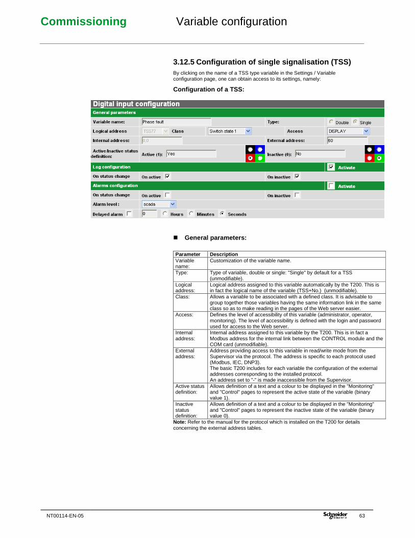
Commissioning Variable configuration
NT00114-EN-05 63
3.12.5 Configuration of single signalisation (TSS) By clicking on the name of a TSS type variable in the Settings / Variable configuration page, one can obtain access to its settings, namely:
Configuration of a TSS: � General parameters:
Parameter Description Variable name:
Customization of the variable name.
Type: Type of variable, double or single: "Single" by default for a TSS (unmodifiable).
Logical address:
Logical address assigned to this variable automatically by the T200. This is in fact the logical name of the variable (TSS+No.) (unmodifiable).
Class: Allows a variable to be associated with a defined class. It is advisable to group together those variables having the same information link in the same class so as to make reading in the pages of the Web server easier.
Access: Defines the level of accessibility of this variable (administrator, operator, monitoring). The level of accessibility is defined with the login and password used for access to the Web server.
Internal address:
Internal address assigned to this variable by the T200. This is in fact a Modbus address for the internal link between the CONTROL module and the COM card (unmodifiable).
External address:
Address providing access to this variable in read/write mode from the Supervisor via the protocol. The address is specific to each protocol used (Modbus, IEC, DNP3). The basic T200 includes for each variable the configuration of the external addresses corresponding to the installed protocol. An address set to "-" is made inaccessible from the Supervisor.
Active status definition:
Allows definition of a text and a colour to be displayed in the "Monitoring" and "Control" pages to represent the active state of the variable (binary value 1).
Inactive status definition:
Allows definition of a text and a colour to be displayed in the "Monitoring" and "Control" pages to represent the inactive state of the variable (binary value 0).
Note: Refer to the manual for the protocol which is installed on the T200 for details concerning the external address tables.
Commissioning Variable configuration
64 NT00114-EN-05
� Record configuration:
By record is meant the saving of changes of state in the event log. Parameter Description "Activate" check box
Check this box to activate saving of the variable in the event log according to the following configured criteria.
On active Check this box to save a change of state in the active state of the variable in the event log.
On inactive Check this box to save a change of state in the inactive state of the variable in the event log.
� Alarm configuration: By alarm is meant the saving of changes of state in the alarm log, but also: - In PSTN or GSM mode : call sequence to the Supervisor then retransmission of the alarm corresponding to the change of state. - In radio mode : sending of a frame to the Supervisor to retransmit the alarm corresponding to the change of state. Comment: The alarms are not used on permanent links. The following configuration should not be used for a permanent link: Parameter Description "Activate" check box:
Check this box to activate saving of the variable in the alarm log according to the following configured criteria.
On active: Check this box to save a change of state in the active state of the variable in the alarm log.
On inactive: Check this box to save a change of state in the inactive state of the variable in the alarm log.
Alarm level: Three configurable levels corresponding to the various possibilities for alarm retransmission to the Supervisor (see section on "Alarm reporting / Alarm acknowledgement"
"Time-delayed alarm" check box:
Check this box if the alarm is to be retransmitted to the Supervisor only after a configurable time delay.
Time-delayed alarm:
Choice of the unit (hour, minute, second) and the waiting time before retransmission of the alarm.
� TSS test: The "TSS test" button at the bottom of the TSS configuration page allows the TSS to be made active (fictitiously) for a few seconds (10 seconds). That makes it possible, for example, to perform testing of state retransmission to the Supervisor, although without being obliged actually to generate the change of state for this TSS.
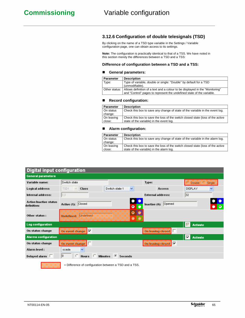
Commissioning Variable configuration
NT00114-EN-05 65
3.12.6 Configuration of double telesignals (TSD) By clicking on the name of a TSD type variable in the Settings / Variable configuration page, one can obtain access to its settings. Note: The configuration is practically identical to that of a TSS. We have noted in this section merely the differences between a TSD and a TSS: Difference of configuration between a TSD and a TSS : � General parameters:
Parameter Description Type: Type of variable, double or single: "Double" by default for a TSD
(unmodifiable). Other status: Allows definition of a text and a colour to be displayed in the "Monitoring"
and "Control" pages to represent the undefined state of the variable. � Record configuration:
Parameter Description On status change:
Check this box to save any change of state of the variable in the event log.
On leaving close:
Check this box to save the loss of the switch closed state (loss of the active state of the variable) in the event log.
� Alarm configuration:
Parameter Description On status change:
Check this box to save any change of state of the variable in the alarm log.
On leaving close:
Check this box to save the loss of the switch closed state (loss of the active state of the variable) in the alarm log.
= Difference of configuration between a TSD and a TSS.
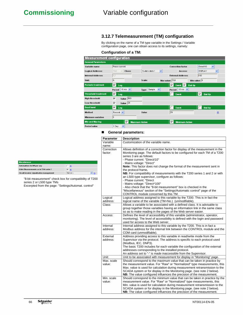
Commissioning Variable configuration
66 NT00114-EN-05
"8-bit measurement" check box for compatibility of T200 series 2 or L500 type TMs Excerpted from the page: "Settings/Automat. control"
3.12.7 Telemeasurement (TM) configuration By clicking on the name of a TM type variable in the Settings / Variable configuration page, one can obtain access to its settings, namely:
Configuration of a TM: � General parameters:
Parameter Description Variable name:
Customization of the variable name.
Correction factor:
Allows definition of a correction factor for display of the measurement in the Monitoring page. The default factors to be configured for each TM of a T200 series 3 are as follows: - Phase current: "Direct/10" - Mains voltage: "Direct" Note: This factor does not change the format of the measurement sent in the protocol frame. NB: For compatibility of measurements with the T200 series 1 and 2 or with an L500 type supervisor, configure as follows: - Phase current: "Direct - Mains voltage: "Direct*100" - Also check that the "8-bit measurement" box is checked in the "Miscellaneous" section of the "Settings/Automatic control" page of the CONTROL module concerned by this TM.
Logical address:
Logical address assigned to this variable by the T200. This is in fact the logical name of the variable (TM+No.) (unmodifiable).
Class: Allows a variable to be associated with a defined class. It is advisable to group together those variables having an information link in the same class so as to make reading in the pages of the Web server easier.
Access: Defines the level of accessibility of this variable (administrator, operator, monitoring). The level of accessibility is defined with the login and password used for access to the Web server.
Internal address:
Internal address assigned to this variable by the T200. This is in fact a Modbus address for the internal link between the CONTROL module and the COM card (unmodifiable).
External address:
Address providing access to this variable in read/write mode from the Supervisor via the protocol. The address is specific to each protocol used (Modbus, IEC, DNP3). The basic T200 includes for each variable the configuration of the external addresses corresponding to the installed protocol. An address set to "-" is made inaccessible from the Supervisor.
Unit: Unit to be associated with measurement for display in "Monitoring" page. Max. scale value:
Should correspond to the maximum value that can be taken in practice by the measurement value. For "Raw" or "Normalized" type measurements, this Max. value is used for calculation during measurement retransmission to the SCADA system or for display in the Monitoring page. (see note 2 below). NB: The value configured influences the precision of the measurement.
Min. scale value:
Should correspond to the minimum value that can be taken in practice by the measurement value. For "Raw" or "Normalized" type measurements, this Min. value is used for calculation during measurement retransmission to the SCADA system or for display in the Monitoring page. (see note 2 below). NB: The value configured influences the precision of the measurement.
Commissioning Variable configuration
NT00114-EN-05 67
Note: Refer to the manual for the protocol which is installed on the T200 for details concerning the external address tables. Note 2 : The T200 manages the transmission of measurements to the SCADA system and measurement display in the "Monitoring" page according to two formats: � Direct (or adjusted) value: corresponds to the real value in the reference unit
(does not take into account the configured "Min. and Max. scale" values). � Raw (or normalized) value: corresponds to a value calculated and scaled in
accordance with a formula taking into account the configured "Min. and Max. scale" values. (see the protocol User Manual for details concerning measurement calculation).
The choice of "Normalized" or "Adjusted" configuration is generally made in the "Protocol" page. � Periodic treatment: Parameter Description "Log" check box: Check this box to activate saving of the measurement in the
measurement log according to the criteria configured below. Period: Can be used to choose the period for saving of the measurement in the
measurement log. Type: Can be used to choose how to save the measurement:
- "Averaged": mean of measurements over the configured period - "Sampled": instantaneous measurement at each configured period
"Event" check box:
Check this box to activate saving of the measurement in the protocol event stack according to the period criteria configured below. (see notes 1 and 2 below)
Period: Can be used to choose the period for saving of the measurement in the protocol stack and/or the alarm log
"Dial up" check box:
Check this box to activate saving of the measurement in the alarm log and sending of a frame to the Supervisor according to the period criterion configured above.
Comment: The alarms are not used on permanent links. The "Call" check box should not be used for a permanent link. Note 1: The measurements cannot be saved in the internal event log. Note 2: The Modbus protocol of the T200 does not enable measurements to be saved in the protocol event stack. It is therefore no use checking the "Events" box for this protocol. The solution for retransmitting the measurements in Modbus protocol is: - On a permanent link: They will be read during the next interrogations coming from the Supervisor. There is therefore nothing special to do. - On a non-permanent link: Check the "Call" box to retransmit it immediately (or after the configured period), or wait for the next interrogation by the Supervisor. � Threshold treatment: Parameter Description "Log" check box: Check this box to activate saving of the measurement in the
measurement log according to the criteria configured below. High threshold: Check the box to activate saving of the measurement upon exceeding
the high threshold. High threshold value
Configure the high threshold value which will cause processing of the defined records.
Low threshold: Check the box to activate saving of the measurement upon exceeding the low threshold.
Low threshold value
Configure the low threshold value which will cause processing of the defined records.
"Dial up" check box:
Check this box to activate saving of the measurement in the alarm log and sending of a frame to the Supervisor according to the threshold criteria configured above.
Comment: The alarms are not used on permanent links. The "Call" check box should not be used for a permanent link. Note 1: Same as for previous section. Note 2: Same as for previous section.
Commissioning Variable configuration
68 NT00114-EN-05
� Dead band: Parameter Description "Log" check box: Check this box to activate saving of the measurement in the
measurement log according to the % criterion configured below. Method: Fixed: A fixed change in the value of the variable results in an
associated processing operation (saving, alarm). Percentage: A change in percentage of the variable results in an associated processing operation.
Value: Configure the minimum variation percentage or the minimum fixed value of measurement variation which will cause processing of the defined records.
Minimum change: Whatever the method (fixed or percentage), a minimum change in the value of the TM is necessary for the variable to be processed (event, alarm, etc.).
"Event" check box:
Check this box to activate saving of the measurement in the protocol event stack according to the % criterion configured above. (see notes 1 and 2 below)
"Dial up" check box:
Check this box to activate saving of the measurement in the alarm log and sending of a frame to the Supervisor according to the % criterion configured above.
Comment: The alarms are not used on permanent links. The "Call" check box should not be used for a permanent link. Note 1 and Note 2: Same as for previous section. Note 3: On software V2.xx, the "Method" and "Minimum change" parameters are not available. Processing is performed on a percentage and without a minimum change. � Min. and Max. recording: Parameter Description "Maximum active" check box:
Check this box to activate saving in the measurement log of the maximum value reached in the period configured below.
"Minimum active" check box:
Check this box to activate saving in the measurement log of the minimum value reached in the period configured below.
Period value: Can be used to configure the period for saving of the measurement in the measurement log.
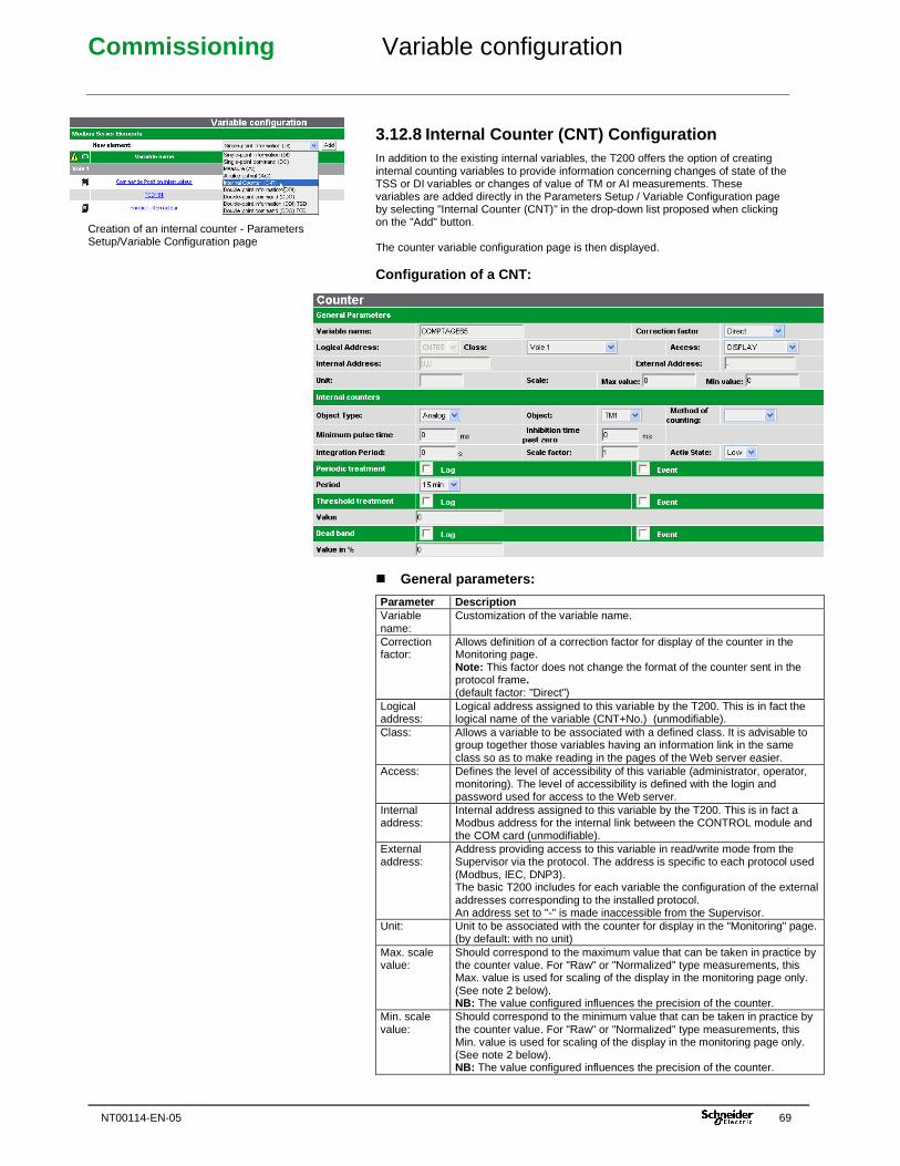
Commissioning Variable configuration
NT00114-EN-05 69
Creation of an internal counter - Parameters Setup/Variable Configuration page
3.12.8 Internal Counter (CNT) Configuration In addition to the existing internal variables, the T200 offers the option of creating internal counting variables to provide information concerning changes of state of the TSS or DI variables or changes of value of TM or AI measurements. These variables are added directly in the Parameters Setup / Variable Configuration page by selecting "Internal Counter (CNT)" in the drop-down list proposed when clicking on the "Add" button. The counter variable configuration page is then displayed. Configuration of a CNT:
� General parameters:
Parameter Description Variable name:
Customization of the variable name.
Correction factor:
Allows definition of a correction factor for display of the counter in the Monitoring page. Note: This factor does not change the format of the counter sent in the protocol frame. (default factor: "Direct")
Logical address:
Logical address assigned to this variable by the T200. This is in fact the logical name of the variable (CNT+No.) (unmodifiable).
Class: Allows a variable to be associated with a defined class. It is advisable to group together those variables having an information link in the same class so as to make reading in the pages of the Web server easier.
Access: Defines the level of accessibility of this variable (administrator, operator, monitoring). The level of accessibility is defined with the login and password used for access to the Web server.
Internal address:
Internal address assigned to this variable by the T200. This is in fact a Modbus address for the internal link between the CONTROL module and the COM card (unmodifiable).
External address:
Address providing access to this variable in read/write mode from the Supervisor via the protocol. The address is specific to each protocol used (Modbus, IEC, DNP3). The basic T200 includes for each variable the configuration of the external addresses corresponding to the installed protocol. An address set to "-" is made inaccessible from the Supervisor.
Unit: Unit to be associated with the counter for display in the "Monitoring" page. (by default: with no unit)
Max. scale value:
Should correspond to the maximum value that can be taken in practice by the counter value. For "Raw" or "Normalized" type measurements, this Max. value is used for scaling of the display in the monitoring page only. (See note 2 below). NB: The value configured influences the precision of the counter.
Min. scale value:
Should correspond to the minimum value that can be taken in practice by the counter value. For "Raw" or "Normalized" type measurements, this Min. value is used for scaling of the display in the monitoring page only. (See note 2 below). NB: The value configured influences the precision of the counter.
Commissioning Variable configuration
70 NT00114-EN-05
Note: Refer to the manual for the protocol which is installed on the T200 for details concerning the external address tables. Note 2 : The T200 manages measurement display in the "Monitoring" page according to two formats: � Direct (or adjusted) value: corresponds to the real value in the reference unit
(does not take into account the configured "Min. and Max. scale" values). � Raw (or normalized) value: corresponds to a value calculated and scaled in
accordance with a formula taking into account the configured "Min. and Max. scale" values. (See the protocol User Manual for details concerning the calculation).
The choice of "Normalized" or "Adjusted" configuration is generally made in the "Protocol" page. It should be noted that, unlike the measurements, the Min. and Max. values configured for the counters do not affect counter sending in the protocol frames to the Supervisor. � Internal counting: Parameter Description Type of object Selection of the variable type on which the counter is incremented
(Digital or Analogue) Object Name of the variable to which the counter is assigned Counting method Depending on the type of object, the methods displayed are as follows:
� For a DI type variable: � Pulse counter: The counter is incremented at each switchover of the variable to high state. � Time counter: The T200 calculates the period during which the variable is in the high or low state. The display in the monitoring page is in the form "day, hour, minute, second". � Integrating meter: Over a given range of time (integration period), the T200 calculates the number of high states of the variable. For example, the integrating meter makes it possible to obtain power values from a power meter with pulse output. � For an AI/AO type variable: � Integrating meter: The meter is incremented each second by the current value of the defined analogue variable. For example, the T200 can poll power type analogue variables on the Modbus Master port; the meter can then obtain the energy from the power calculation. � “Mean” counter: The counter analyses an analogue variable and displays the mean value of the variable over the configured integration period. This function allows smoothing of analogue variables in particular.
Pulse width Pulse length (in ms) after which the T200 will consider a state as high. Inhibition after reset
Period during which the T200 inhibits pulse detection after zero crossing by the variable. This filter makes it possible to avoid possible rebounds in the event of a return to zero.
Integration period Useful period of the measurement in the case of an integrating meter (DI type variable) or mean (AI type variable)
Conversion factor Used in the case of a pulse counter. Weight of the pulse sent. With each pulse sent, the counter value is incremented in accordance with the conversion factor.
Active state Field used only in the case of a time counter. State of the variable (high or low) which activates the time counter.
� Routine processing: Parameter Description "Recording" check box:
Check this box to activate saving of the counter in the measurement log according to the criterion configured below.
"Event" check box:
Check this box to activate saving of the counter in the protocol event stack according to the period criterion configured below. (see notes 1 and 2 below)
Period: Can be used to choose the period for saving of the counter in the measurement log and in the protocol stack to the Supervisor.
Note 1: The counters cannot be saved in the internal event log. Note 2: The Modbus protocol of the T200 does not enable counters to be saved in the protocol event stack. It is therefore no use checking the "Events" box for this protocol.
Commissioning Variable configuration
NT00114-EN-05 71
The solution for retransmitting the counters in Modbus protocol is: - On a permanent link: They will be read during the next interrogations coming from the Supervisor. There is therefore nothing special to do. � Processing on threshold: Parameter Description "Recording" check box:
Check this box to activate saving of the counter in the measurement log according to the value criterion configured below.
"Event" check box:
Check this box to activate saving of the counter in the protocol event stack according to the criterion configured below.
Value Configure the minimum value which will cause processing of the records defined above.
Note 1: Same as for previous section. Note 2: Same as for previous section. � Dead band: Parameter Description "Recording" check box:
Check this box to activate saving of the counter in the measurement log according to the % criterion configured below.
"Event" check box:
Check this box to activate saving of the counter in the protocol event stack according to the criterion configured below.
Value as %: Configure the minimum counter variation percentage which will cause processing of the records defined above.
Note 1: Same as for previous section. Note 2: Same as for previous section.
3.12.9 Summary of records in logs and stacks: The following table summarizes the various possibilities for recording in the various logs and in the protocol event stack according to each type of variable:
Type Event log Alarm log Measurement log
Protocol event stack
TSS If corresponding check box checked
If corresponding check box checked
Always
TSD If corresponding check box checked
If corresponding check box checked
Always
TM If "Dial up" check box checked
If "Log" check box checked
If "Event" check box checked (see note below)
CNT If "Log" check box checked
If "Event" check box checked (see note below)
Note: For a TM or a CNT, several measurement processing operations can be performed according to the type of transmission: - "Event" box only checked : Saving of the TM or a CNT in the protocol stack without call sequence to the Supervisor (general case of the permanent link, except in Modbus protocol). - "Event" + "Dial up" boxes checked : Saving of the TM in the protocol stack and call to the Supervisor (general case of the non-permanent link). Not applicable with CNT. - "Dial up" box only checked : Call to the Supervisor without saving of the TM in the protocol stack (specific case of the non-permanent link in Modbus protocol). Not applicable with CNT. Note : With Modbus protocol, the "Log" check box has no action.
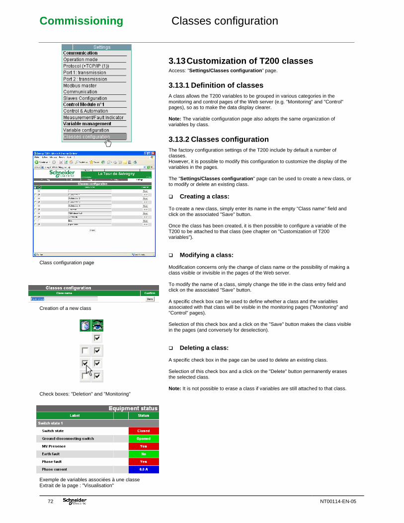
Commissioning Classes configuration
72 NT00114-EN-05
Class configuration page Creation of a new class Check boxes: "Deletion" and "Monitoring" Exemple de variables associées à une classe Extrait de la page : "Visualisation"
3.13 Customization of T200 classes Access: "Settings/Classes configuration " page.
3.13.1 Definition of classes A class allows the T200 variables to be grouped in various categories in the monitoring and control pages of the Web server (e.g. "Monitoring" and "Control" pages), so as to make the data display clearer. Note: The variable configuration page also adopts the same organization of variables by class.
3.13.2 Classes configuration The factory configuration settings of the T200 include by default a number of classes. However, it is possible to modify this configuration to customize the display of the variables in the pages. The "Settings/Classes configuration " page can be used to create a new class, or to modify or delete an existing class. � Creating a class: To create a new class, simply enter its name in the empty "Class name" field and click on the associated "Save" button. Once the class has been created, it is then possible to configure a variable of the T200 to be attached to that class (see chapter on "Customization of T200 variables"). � Modifying a class: Modification concerns only the change of class name or the possibility of making a class visible or invisible in the pages of the Web server. To modify the name of a class, simply change the title in the class entry field and click on the associated "Save" button. A specific check box can be used to define whether a class and the variables associated with that class will be visible in the monitoring pages ("Monitoring" and "Control" pages). Selection of this check box and a click on the "Save" button makes the class visible in the pages (and conversely for deselection). � Deleting a class: A specific check box in the page can be used to delete an existing class. Selection of this check box and a click on the "Delete" button permanently erases the selected class. Note: It is not possible to erase a class if variables are still attached to that class.
Commissioning Tests
NT00114-EN-05 73
See the “Operation” chapter for more information concerning the operation of the Easergy T200. See “Operation” for a step-by-step description of the various transmission stages indicated by the LEDs on the front panel of the Communication module.
3.14 Tests at commissioning During the tests, a microcomputer designed for configuration of the T200 can remain connected to the Communication module. It can be used to monitor the status of the equipment, time-stamped events and communications sent over the internal Modbus link. Commissioning sheet ref. N1030 can be used.
“Local/Remote” switch set to “Local” � Check that the PC has taken the “local equipment” information into account. � Check that the MV cubicle switchgear is operating correctly, for example that each channel can open and close and that the positions of the switches correspond to the status of the indicator lamps. � Check “locked” information (earthing switch): Check that the equipment has taken the “locked” inputs into account.
“Local/Remote” switch set to “Remote” � Check that the status of the MV cubicles is correctly displayed on the control station. � Check that the cubicle connecting cables are correctly marked and disconnect them: a remote alarm is generated after a one-minute time-out. � Check that the HA10 cubicle connectors are fitted with polarizing pins. If you have dummy devices, install them on the HA10 connectors to ensure that neither the battery nor the MV cubicle is overloaded. � Telecontrol order check: � Check that each order processed by the remote control station is correctly transmitted and executed by the equipment, for example that each channel can open and close. � Check that the switch position information received at the remote control station corresponds to the status of the indicator lamps. � “Digital inputs” check: Check that the equipment has taken the “Digital inputs” into account and that the indications have been forwarded to the remote control station. � Check the internal fault current detection function: The “Test” pushbutton on the Control module activates the notifications corresponding only to those channels for which Current Acquisition cards are installed. Note: A current simulator supplied as an optional extra can be used for this check. It performs a complete test of the acquisition system. Disconnect the dummy devices and reconnect the cubicle connecting cables to their HA10 connector (polarization). � Telecontrol order check: � Check that each order processed by the remote control station is correctly transmitted and executed by the equipment, for example that each channel can open and close. � Check that the switch position information received at the remote control station corresponds to the status of the indicator lamps. � Check “locked” information (earthing switch): Check that the equipment has taken the “Locked” inputs into account and that the notifications have been forwarded to the remote control station. � “AC supply OFF” alarm check: Open the AC supply fuse block. The remote alarm is generated immediately, or after the configured time-out.
IMPORTANT NOTE: These tests can store time-stamped events. Remember to erase them from the configuration PC.
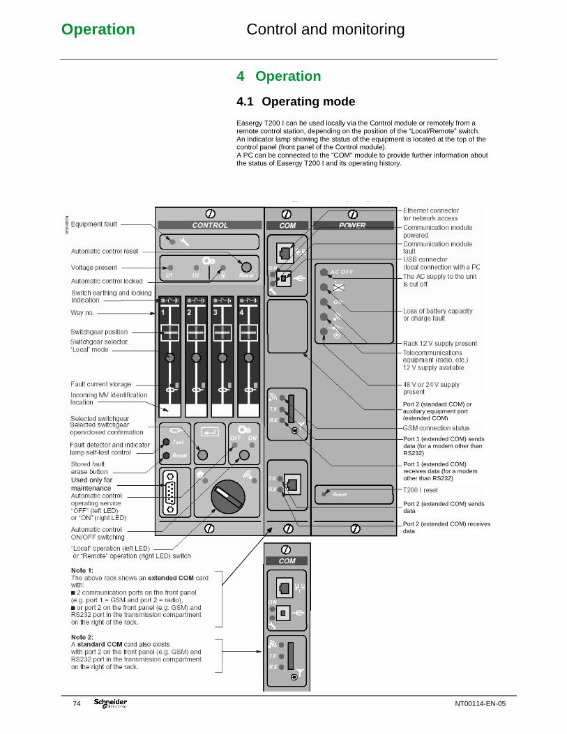
Operation Control and monitoring
74 NT00114-EN-05
4 Operation
4.1 Operating mode Easergy T200 I can be used locally via the Control module or remotely from a remote control station, depending on the position of the “Local/Remote” switch. An indicator lamp showing the status of the equipment is located at the top of the control panel (front panel of the Control module). A PC can be connected to the "COM" module to provide further information about the status of Easergy T200 I and its operating history.
Port 2 (standard COM) or auxiliary equipment port (extended COM)
Port 1 (extended COM) sends data (for a modem other than RS232)
Port 1 (extended COM) receives data (for a modem other than RS232)
Port 2 (extended COM) sends data
Port 2 (extended COM) receives data
Used only for maintenance
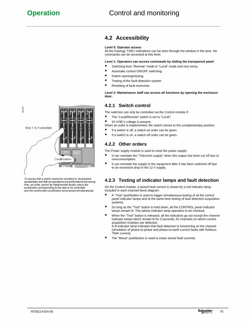
Operation Control and monitoring
NT00114-EN-05 75
4.2 Accessibility Level 0: Operator access All the Easergy T200 I indications can be seen through the window in the door. No commands can be accessed at this level. Level 1: Operators can access commands by sliding t he transparent panel
� Switching from “Remote” mode to “Local” mode and vice versa.
� Automatic control ON/OFF switching.
� Switch opening/closing.
� Testing of the fault detection system.
� Resetting of fault memories. Level 2: Maintenance staff can access all functions by opening the enclosure door.
4.2.1 Switch control The switches can only be controlled via the Control module if:
� The “Local/Remote” switch is set to “Local”;
� 24 V/48 V voltage is present; When an order is implemented, the switch moves to the complementary position:
� If a switch is off, a switch-on order can be given.
� If a switch is on, a switch-off order can be given.
4.2.2 Other orders The Power supply module is used to reset the power supply:
� It can reinstate the “Telecoms supply” when this output has been cut off due to overconsumption.
� It can reinstate the supply to the equipment after it has been switched off due to an excessive drop in the 12 V supply.
4.2.3 Testing of indicator lamps and fault detectio n On the Control module, a stored fault current is shown by a red indicator lamp included in each channel block diagram.
� A “Test” pushbutton is used to trigger simultaneous testing of all the control panel indicator lamps and at the same time testing of fault detection acquisition systems.
� So long as the "Test" button is held down, all the CONTROL panel indicator lamps remain lit. This allows indicator lamp operation to be checked.
� When the "Test" button is released, all the indicators go out except the channel indicator lamps which remain lit for 3 seconds, for channels on which current acquisition modules are detected. A lit indicator lamp indicates that fault detection is functioning on the channel (simulation of phase-to-phase and phase-to-earth current faults with fictitious 750A current).
� The “Reset” pushbutton is used to erase stored fault currents.
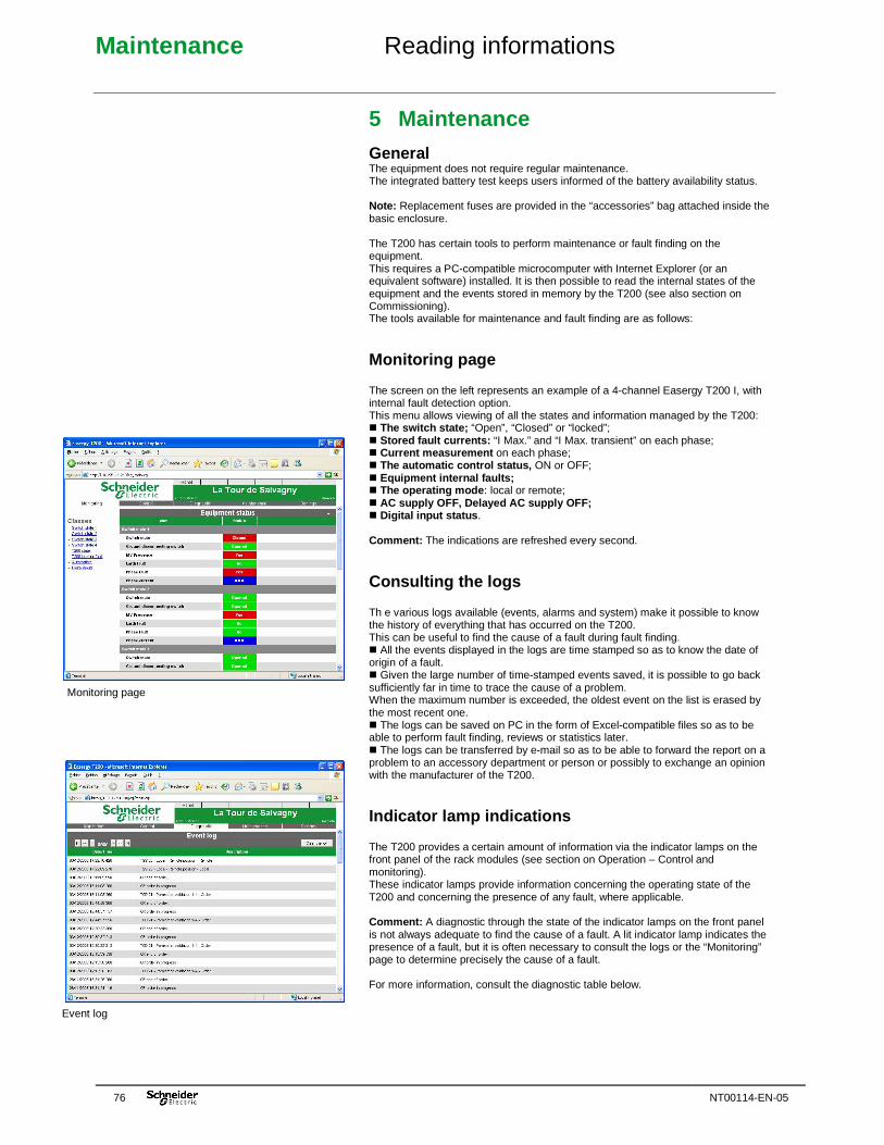
Maintenance Reading informations
76 NT00114-EN-05
5 Maintenance
General The equipment does not require regular maintenance. The integrated battery test keeps users informed of the battery availability status. Note: Replacement fuses are provided in the “accessories” bag attached inside the basic enclosure. The T200 has certain tools to perform maintenance or fault finding on the equipment. This requires a PC-compatible microcomputer with Internet Explorer (or an equivalent software) installed. It is then possible to read the internal states of the equipment and the events stored in memory by the T200 (see also section on Commissioning). The tools available for maintenance and fault finding are as follows:
Monitoring page The screen on the left represents an example of a 4-channel Easergy T200 I, with internal fault detection option. This menu allows viewing of all the states and information managed by the T200: � The switch state; “Open”, “Closed” or “locked”; � Stored fault currents: “I Max.” and “I Max. transient” on each phase; � Current measurement on each phase; � The automatic control status, ON or OFF; � Equipment internal faults; � The operating mode : local or remote; � AC supply OFF, Delayed AC supply OFF; � Digital input status . Comment: The indications are refreshed every second.
Consulting the logs Th e various logs available (events, alarms and system) make it possible to know the history of everything that has occurred on the T200. This can be useful to find the cause of a fault during fault finding. � All the events displayed in the logs are time stamped so as to know the date of origin of a fault. � Given the large number of time-stamped events saved, it is possible to go back sufficiently far in time to trace the cause of a problem. When the maximum number is exceeded, the oldest event on the list is erased by the most recent one. � The logs can be saved on PC in the form of Excel-compatible files so as to be able to perform fault finding, reviews or statistics later. � The logs can be transferred by e-mail so as to be able to forward the report on a problem to an accessory department or person or possibly to exchange an opinion with the manufacturer of the T200.
Indicator lamp indications The T200 provides a certain amount of information via the indicator lamps on the front panel of the rack modules (see section on Operation – Control and monitoring). These indicator lamps provide information concerning the operating state of the T200 and concerning the presence of any fault, where applicable. Comment: A diagnostic through the state of the indicator lamps on the front panel is not always adequate to find the cause of a fault. A lit indicator lamp indicates the presence of a fault, but it is often necessary to consult the logs or the “Monitoring” page to determine precisely the cause of a fault. For more information, consult the diagnostic table below.
Monitoring page
Event log
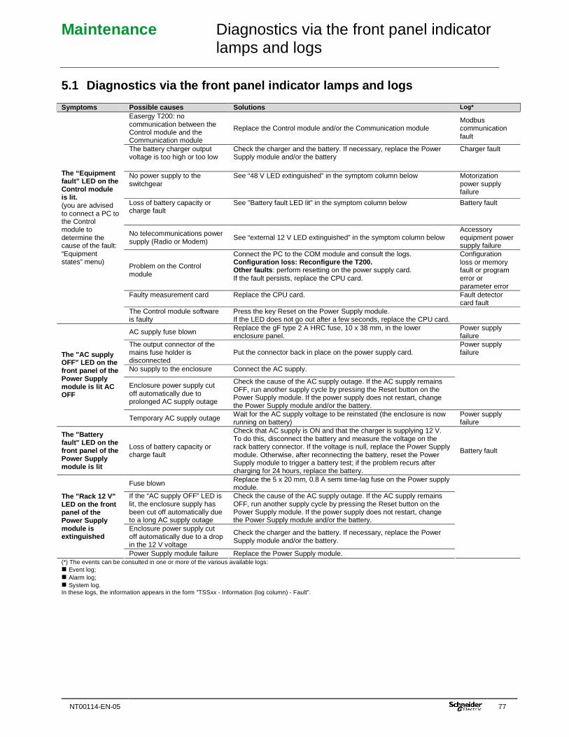
Maintenance Diagnostics via the front panel indicator lamps and logs
NT00114-EN-05 77
5.1 Diagnostics via the front panel indicator lamps and logs Symptoms Possible causes Solutions Log*
Easergy T200: no communication between the Control module and the Communication module
Replace the Control module and/or the Communication module Modbus communication fault
The battery charger output voltage is too high or too low
Check the charger and the battery. If necessary, replace the Power Supply module and/or the battery
Charger fault
No power supply to the switchgear
See “48 V LED extinguished” in the symptom column below Motorization power supply failure
Loss of battery capacity or charge fault
See "Battery fault LED lit" in the symptom column below Battery fault
No telecommunications power supply (Radio or Modem)
See “external 12 V LED extinguished” in the symptom column below Accessory equipment power supply failure
Problem on the Control module
Connect the PC to the COM module and consult the logs. Configuration loss: Reconfigure the T200. Other faults : perform resetting on the power supply card. If the fault persists, replace the CPU card.
Configuration loss or memory fault or program error or parameter error
Faulty measurement card Replace the CPU card. Fault detector card fault
The “Equipment fault” LED on the Control module is lit. (you are advised to connect a PC to the Control module to determine the cause of the fault: “Equipment states” menu)
The Control module software is faulty
Press the key Reset on the Power Supply module. If the LED does not go out after a few seconds, replace the CPU card.
AC supply fuse blown Replace the gF type 2 A HRC fuse, 10 x 38 mm, in the lower enclosure panel.
Power supply failure
The output connector of the mains fuse holder is disconnected
Put the connector back in place on the power supply card. Power supply failure
No supply to the enclosure Connect the AC supply. Enclosure power supply cut off automatically due to prolonged AC supply outage
Check the cause of the AC supply outage. If the AC supply remains OFF, run another supply cycle by pressing the Reset button on the Power Supply module. If the power supply does not restart, change the Power Supply module and/or the battery.
The "AC supply OFF" LED on the front panel of the Power Supply module is lit AC OFF
Temporary AC supply outage Wait for the AC supply voltage to be reinstated (the enclosure is now running on battery)
Power supply failure
The "Battery fault" LED on the front panel of the Power Supply module is lit
Loss of battery capacity or charge fault
Check that AC supply is ON and that the charger is supplying 12 V. To do this, disconnect the battery and measure the voltage on the rack battery connector. If the voltage is null, replace the Power Supply module. Otherwise, after reconnecting the battery, reset the Power Supply module to trigger a battery test; if the problem recurs after charging for 24 hours, replace the battery.
Battery fault
Fuse blown Replace the 5 x 20 mm, 0.8 A semi time-lag fuse on the Power supply module.
If the “AC supply OFF” LED is lit, the enclosure supply has been cut off automatically due to a long AC supply outage
Check the cause of the AC supply outage. If the AC supply remains OFF, run another supply cycle by pressing the Reset button on the Power Supply module. If the power supply does not restart, change the Power Supply module and/or the battery.
Enclosure power supply cut off automatically due to a drop in the 12 V voltage
Check the charger and the battery. If necessary, replace the Power Supply module and/or the battery.
The "Rack 12 V" LED on the front panel of the Power Supply module is extinguished
Power Supply module failure Replace the Power Supply module. (*) The events can be consulted in one or more of the various available logs: � Event log; � Alarm log; � System log. In these logs, the information appears in the form "TSSxx - Information (log column) - Fault".
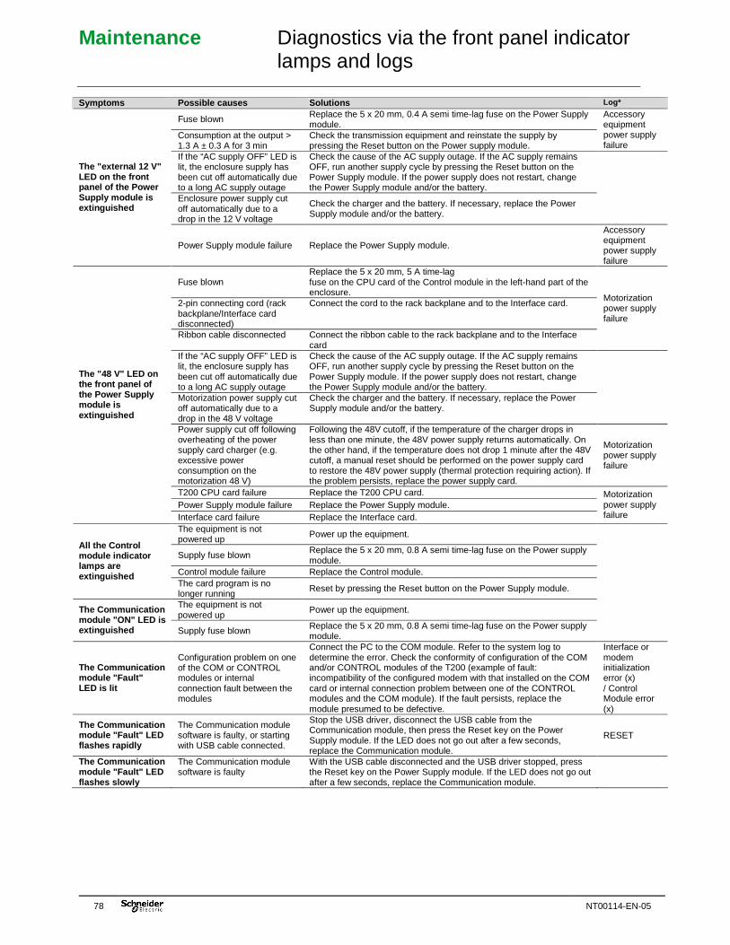
Maintenance Diagnostics via the front panel indicator lamps and logs
78 NT00114-EN-05
Symptoms Possible causes Solutions Log*
Fuse blown Replace the 5 x 20 mm, 0.4 A semi time-lag fuse on the Power Supply module.
Consumption at the output > 1.3 A ± 0.3 A for 3 min
Check the transmission equipment and reinstate the supply by pressing the Reset button on the Power supply module.
Accessory equipment power supply failure
If the “AC supply OFF” LED is lit, the enclosure supply has been cut off automatically due to a long AC supply outage
Check the cause of the AC supply outage. If the AC supply remains OFF, run another supply cycle by pressing the Reset button on the Power Supply module. If the power supply does not restart, change the Power Supply module and/or the battery.
Enclosure power supply cut off automatically due to a drop in the 12 V voltage
Check the charger and the battery. If necessary, replace the Power Supply module and/or the battery.
The "external 12 V" LED on the front panel of the Power Supply module is extinguished
Power Supply module failure Replace the Power Supply module.
Accessory equipment power supply failure
Fuse blown Replace the 5 x 20 mm, 5 A time-lag fuse on the CPU card of the Control module in the left-hand part of the enclosure.
2-pin connecting cord (rack backplane/Interface card disconnected)
Connect the cord to the rack backplane and to the Interface card.
Ribbon cable disconnected Connect the ribbon cable to the rack backplane and to the Interface card
Motorization power supply failure
If the “AC supply OFF” LED is lit, the enclosure supply has been cut off automatically due to a long AC supply outage
Check the cause of the AC supply outage. If the AC supply remains OFF, run another supply cycle by pressing the Reset button on the Power Supply module. If the power supply does not restart, change the Power Supply module and/or the battery.
Motorization power supply cut off automatically due to a drop in the 48 V voltage
Check the charger and the battery. If necessary, replace the Power Supply module and/or the battery.
Power supply cut off following overheating of the power supply card charger (e.g. excessive power consumption on the motorization 48 V)
Following the 48V cutoff, if the temperature of the charger drops in less than one minute, the 48V power supply returns automatically. On the other hand, if the temperature does not drop 1 minute after the 48V cutoff, a manual reset should be performed on the power supply card to restore the 48V power supply (thermal protection requiring action). If the problem persists, replace the power supply card.
Motorization power supply failure
T200 CPU card failure Replace the T200 CPU card. Power Supply module failure Replace the Power Supply module.
The "48 V" LED on the front panel of the Power Supply module is extinguished
Interface card failure Replace the Interface card.
Motorization power supply failure
The equipment is not powered up Power up the equipment.
Supply fuse blown Replace the 5 x 20 mm, 0.8 A semi time-lag fuse on the Power supply module.
Control module failure Replace the Control module.
All the Control module indicator lamps are extinguished
The card program is no longer running
Reset by pressing the Reset button on the Power Supply module.
The equipment is not powered up
Power up the equipment. The Communication module "ON" LED is extinguished Supply fuse blown Replace the 5 x 20 mm, 0.8 A semi time-lag fuse on the Power supply
module.
The Communication module "Fault" LED is lit
Configuration problem on one of the COM or CONTROL modules or internal connection fault between the modules
Connect the PC to the COM module. Refer to the system log to determine the error. Check the conformity of configuration of the COM and/or CONTROL modules of the T200 (example of fault: incompatibility of the configured modem with that installed on the COM card or internal connection problem between one of the CONTROL modules and the COM module). If the fault persists, replace the module presumed to be defective.
Interface or modem initialization error (x) / Control Module error (x)
The Communication module "Fault" LED flashes rapidly
The Communication module software is faulty, or starting with USB cable connected.
Stop the USB driver, disconnect the USB cable from the Communication module, then press the Reset key on the Power Supply module. If the LED does not go out after a few seconds, replace the Communication module.
RESET
The Communication module "Fault" LED flashes slowly
The Communication module software is faulty
With the USB cable disconnected and the USB driver stopped, press the Reset key on the Power Supply module. If the LED does not go out after a few seconds, replace the Communication module.
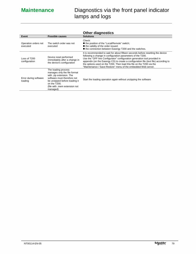
Maintenance Diagnostics via the front panel indicator lamps and logs
NT00114-EN-05 79
Other diagnostics Event Possible causes Solutions
Operation orders not executed
The switch order was not executed
Check: � the position of the “Local/Remote” switch; � the validity of the order issued; � the connection between Easergy T200 and the switches.
Loss of T200 configuration
Device reset performed immediately after a change in the device's configuration
It is recommended to wait for about fifteen seconds before resetting the device following a change in configuration parameters of the T200. Use the "OFF line Configurator" configuration generation tool provided in appendix (on the Easergy CD) to create a configuration file (text file) according to the options used on the T200. Then load this file on the T200 via the "Maintenance / Save-Restore" menu of the embedded Web server.
Error during software loading
The loading process manages only the file format with .zip extension. The software must therefore not be unzipped before loading it on the T200. (file with .mem extension not managed)
Start the loading operation again without unzipping the software
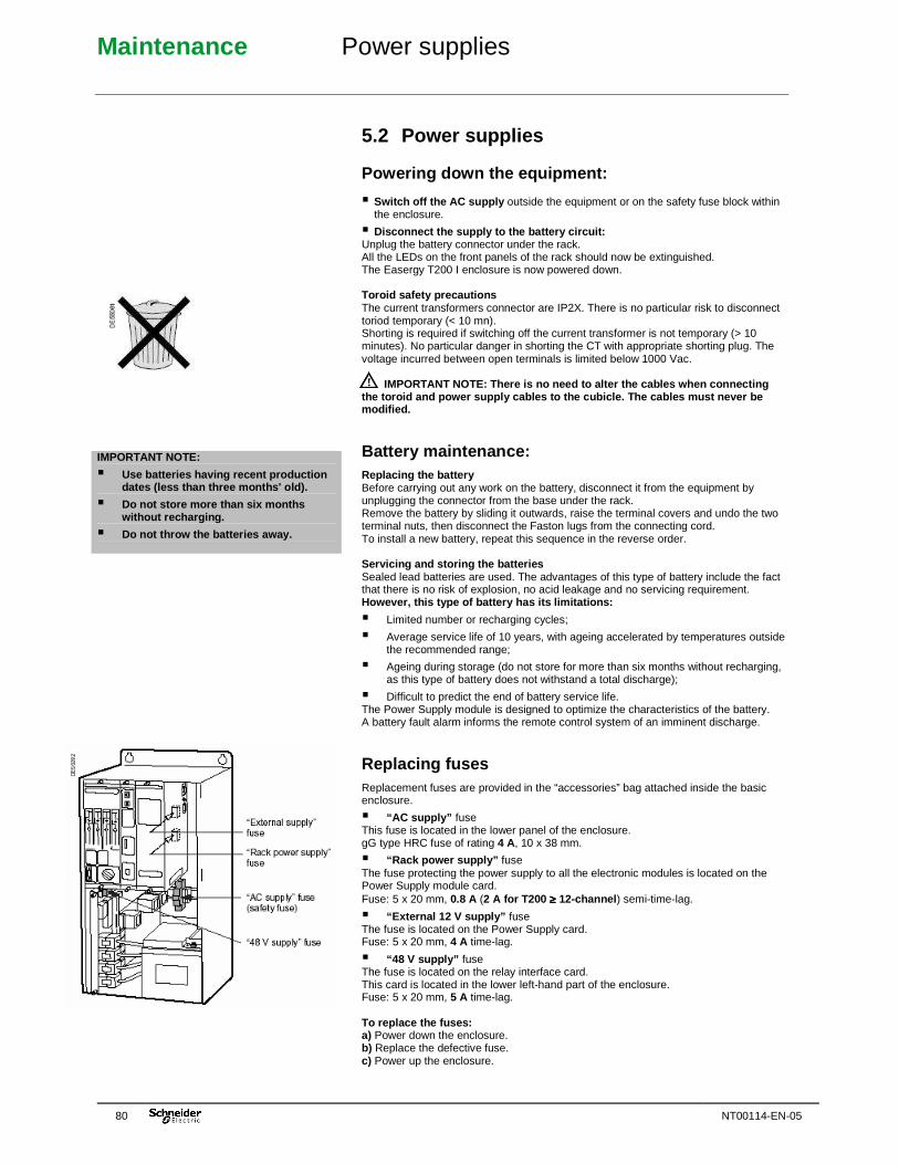
Maintenance Power supplies
80 NT00114-EN-05
IMPORTANT NOTE:
� Use batteries having recent production dates (less than three months' old).
� Do not store more than six months without recharging.
� Do not throw the batteries away.
5.2 Power supplies
Powering down the equipment:
� Switch off the AC supply outside the equipment or on the safety fuse block within the enclosure.
� Disconnect the supply to the battery circuit: Unplug the battery connector under the rack. All the LEDs on the front panels of the rack should now be extinguished. The Easergy T200 I enclosure is now powered down. Toroid safety precautions The current transformers connector are IP2X. There is no particular risk to disconnect toriod temporary (< 10 mn). Shorting is required if switching off the current transformer is not temporary (> 10 minutes). No particular danger in shorting the CT with appropriate shorting plug. The voltage incurred between open terminals is limited below 1000 Vac.
IMPORTANT NOTE: There is no need to alter the cable s when connecting the toroid and power supply cables to the cubicle. The cables must never be modified.
Battery maintenance: Replacing the battery Before carrying out any work on the battery, disconnect it from the equipment by unplugging the connector from the base under the rack. Remove the battery by sliding it outwards, raise the terminal covers and undo the two terminal nuts, then disconnect the Faston lugs from the connecting cord. To install a new battery, repeat this sequence in the reverse order. Servicing and storing the batteries Sealed lead batteries are used. The advantages of this type of battery include the fact that there is no risk of explosion, no acid leakage and no servicing requirement. However, this type of battery has its limitations:
� Limited number or recharging cycles;
� Average service life of 10 years, with ageing accelerated by temperatures outside the recommended range;
� Ageing during storage (do not store for more than six months without recharging, as this type of battery does not withstand a total discharge);
� Difficult to predict the end of battery service life. The Power Supply module is designed to optimize the characteristics of the battery. A battery fault alarm informs the remote control system of an imminent discharge.
Replacing fuses Replacement fuses are provided in the “accessories” bag attached inside the basic enclosure.
� “AC supply” fuse This fuse is located in the lower panel of the enclosure. gG type HRC fuse of rating 4 A, 10 x 38 mm.
� “Rack power supply” fuse The fuse protecting the power supply to all the electronic modules is located on the Power Supply module card. Fuse: 5 x 20 mm, 0.8 A (2 A for T200 ≥≥≥≥ 12-channel ) semi-time-lag.
� “External 12 V supply” fuse The fuse is located on the Power Supply card. Fuse: 5 x 20 mm, 4 A time-lag.
� “48 V supply” fuse The fuse is located on the relay interface card. This card is located in the lower left-hand part of the enclosure. Fuse: 5 x 20 mm, 5 A time-lag. To replace the fuses: a) Power down the enclosure. b) Replace the defective fuse. c) Power up the enclosure.
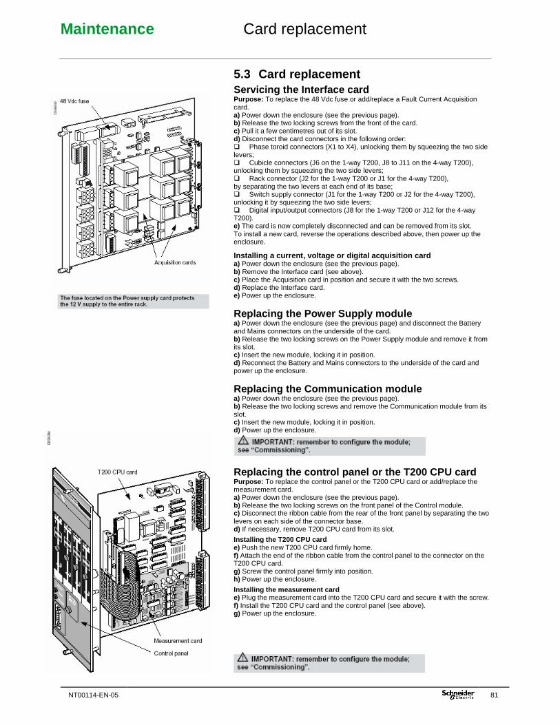
Maintenance Card replacement
NT00114-EN-05 81
5.3 Card replacement Servicing the Interface card Purpose: To replace the 48 Vdc fuse or add/replace a Fault Current Acquisition card. a) Power down the enclosure (see the previous page). b) Release the two locking screws from the front of the card. c) Pull it a few centimetres out of its slot. d) Disconnect the card connectors in the following order: � Phase toroid connectors (X1 to X4), unlocking them by squeezing the two side levers; � Cubicle connectors (J6 on the 1-way T200, J8 to J11 on the 4-way T200), unlocking them by squeezing the two side levers; � Rack connector (J2 for the 1-way T200 or J1 for the 4-way T200), by separating the two levers at each end of its base; � Switch supply connector (J1 for the 1-way T200 or J2 for the 4-way T200), unlocking it by squeezing the two side levers; � Digital input/output connectors (J8 for the 1-way T200 or J12 for the 4-way T200). e) The card is now completely disconnected and can be removed from its slot. To install a new card, reverse the operations described above, then power up the enclosure.
Installing a current, voltage or digital acquisitio n card a) Power down the enclosure (see the previous page). b) Remove the Interface card (see above). c) Place the Acquisition card in position and secure it with the two screws. d) Replace the Interface card. e) Power up the enclosure.
Replacing the Power Supply module a) Power down the enclosure (see the previous page) and disconnect the Battery and Mains connectors on the underside of the card. b) Release the two locking screws on the Power Supply module and remove it from its slot. c) Insert the new module, locking it in position. d) Reconnect the Battery and Mains connectors to the underside of the card and power up the enclosure.
Replacing the Communication module a) Power down the enclosure (see the previous page). b) Release the two locking screws and remove the Communication module from its slot. c) Insert the new module, locking it in position. d) Power up the enclosure.
Replacing the control panel or the T200 CPU card Purpose: To replace the control panel or the T200 CPU card or add/replace the measurement card. a) Power down the enclosure (see the previous page). b) Release the two locking screws on the front panel of the Control module. c) Disconnect the ribbon cable from the rear of the front panel by separating the two levers on each side of the connector base. d) If necessary, remove T200 CPU card from its slot.
Installing the T200 CPU card e) Push the new T200 CPU card firmly home. f) Attach the end of the ribbon cable from the control panel to the connector on the T200 CPU card. g) Screw the control panel firmly into position. h) Power up the enclosure.
Installing the measurement card e) Plug the measurement card into the T200 CPU card and secure it with the screw. f) Install the T200 CPU card and the control panel (see above). g) Power up the enclosure.
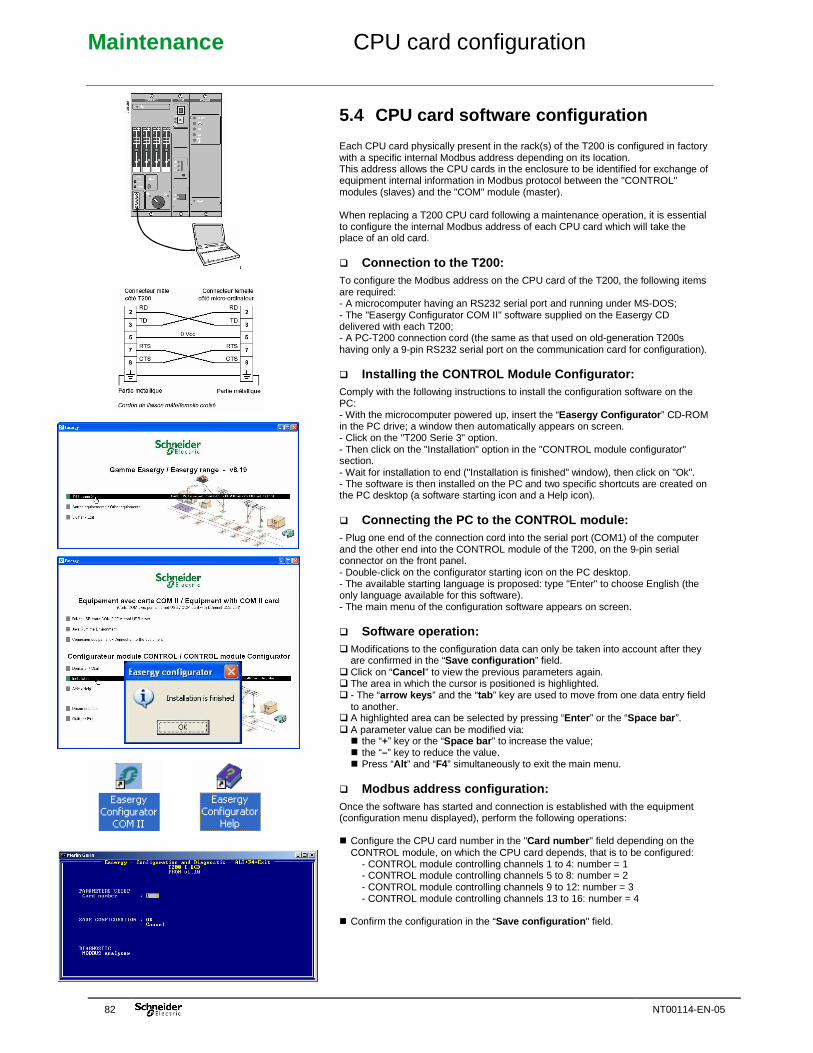
Maintenance CPU card configuration
82 NT00114-EN-05
5.4 CPU card software configuration Each CPU card physically present in the rack(s) of the T200 is configured in factory with a specific internal Modbus address depending on its location. This address allows the CPU cards in the enclosure to be identified for exchange of equipment internal information in Modbus protocol between the "CONTROL" modules (slaves) and the "COM" module (master). When replacing a T200 CPU card following a maintenance operation, it is essential to configure the internal Modbus address of each CPU card which will take the place of an old card. � Connection to the T200: To configure the Modbus address on the CPU card of the T200, the following items are required: - A microcomputer having an RS232 serial port and running under MS-DOS; - The "Easergy Configurator COM II" software supplied on the Easergy CD delivered with each T200; - A PC-T200 connection cord (the same as that used on old-generation T200s having only a 9-pin RS232 serial port on the communication card for configuration). � Installing the CONTROL Module Configurator: Comply with the following instructions to install the configuration software on the PC: - With the microcomputer powered up, insert the “Easergy Configurator ” CD-ROM in the PC drive; a window then automatically appears on screen. - Click on the "T200 Serie 3" option. - Then click on the "Installation" option in the "CONTROL module configurator" section. - Wait for installation to end ("Installation is finished" window), then click on "Ok". - The software is then installed on the PC and two specific shortcuts are created on the PC desktop (a software starting icon and a Help icon). � Connecting the PC to the CONTROL module: - Plug one end of the connection cord into the serial port (COM1) of the computer and the other end into the CONTROL module of the T200, on the 9-pin serial connector on the front panel. - Double-click on the configurator starting icon on the PC desktop. - The available starting language is proposed: type "Enter" to choose English (the only language available for this software). - The main menu of the configuration software appears on screen. � Software operation: � Modifications to the configuration data can only be taken into account after they
are confirmed in the “Save configuration ” field. � Click on “Cancel ” to view the previous parameters again. � The area in which the cursor is positioned is highlighted. � - The “arrow keys ” and the “tab ” key are used to move from one data entry field
to another. � A highlighted area can be selected by pressing “Enter ” or the “Space bar ”. � A parameter value can be modified via:
� the “+” key or the “Space bar ” to increase the value; � the “–” key to reduce the value. � Press “Alt ” and “F4” simultaneously to exit the main menu.
� Modbus address configuration: Once the software has started and connection is established with the equipment (configuration menu displayed), perform the following operations: � Configure the CPU card number in the "Card number " field depending on the
CONTROL module, on which the CPU card depends, that is to be configured: - CONTROL module controlling channels 1 to 4: number = 1 - CONTROL module controlling channels 5 to 8: number = 2 - CONTROL module controlling channels 9 to 12: number = 3 - CONTROL module controlling channels 13 to 16: number = 4
� Confirm the configuration in the “Save configuration " field.
Maintenance CPU card configuration
NT00114-EN-05 83
Note: After saving the configuration, if "Bad card number " appears on the first line of the menu, this means that an incorrect number has been configured or there is a gap in the card numbers (e.g. No. 1 and 3 configured but number 2 missing). NB: If two CONTROL modules have been configured with the same number, the T200 will not be able to operate correctly, because the COM card will detect an internal Modbus address conflict. The red "Fault" indicator lamp on the COM card of the T200 will then light to indicate the occurrence of a configuration problem.
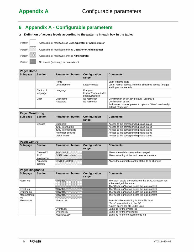
Appendix A Configurable parameters
84 NT00114-EN-05
6 Appendix A - Configurable parameters � Definition of access levels according to the patter ns in each box in the table:
Pattern
: Accessible or modifiable as User, Operator or Administrator
Pattern
: Accessible or modifiable only as Operator or Administrator
Pattern
: Accessible or modifiable only as Administrator
Pattern
: No access (read-only) or non-existent Page: Home Sub-page Section Parameter / button Configuration
range Comments
Home Back to home page Local/Remote Local/Remote Local: normal access. Remote: simplified access (images
and logos not loaded) Choice of language
Language Français/ English/Português/Espagnõl/Deutsch
User name No restriction Confirmation by OK (by default: "Easergy")
User Password No restriction Confirmation by OK
An incorrect user or password opens a "User" session (by default: "Easergy")
Page: Monitoring Sub-page Section Parameter / button Configuration
range Comments
Channel x Access to the corresponding class states T200 information Access to the corresponding class states T200 internal faults Access to the corresponding class states Automatic controls Access to the corresponding class states
Classes
Digital inputs Access to the corresponding class states Page: Control Sub-page Section Parameter / button Configuration
range Comments
Channel X F-O control Allows the switch status to be changed T200 information
DDEF reset control Allows resetting of the fault detector memory
Automatic controls
ON/OFF control Allows the automatic control status to be changed
Page: Diagnostic Sub-page Section Parameter / button Configuration
range Comments
Alarm log Clear log The "Ack" box is checked when the SCADA system has acknowledged the alarm The "Clear log" button clears the log's content
Event log Clear log The "Clear log" button clears the log's content System log Clear log The "Clear log" button clears the log's content Measurement log
Clear log The "Clear log" button clears the log's content
Alarms.csv Transfers the alarms log in Excel file form "Save" saves the file to the PC "Open" opens the file under Excel
Events.csv Same as for the events log System.csv Same as for the system log
File transfer
Measures.csv Same as for the measurements log
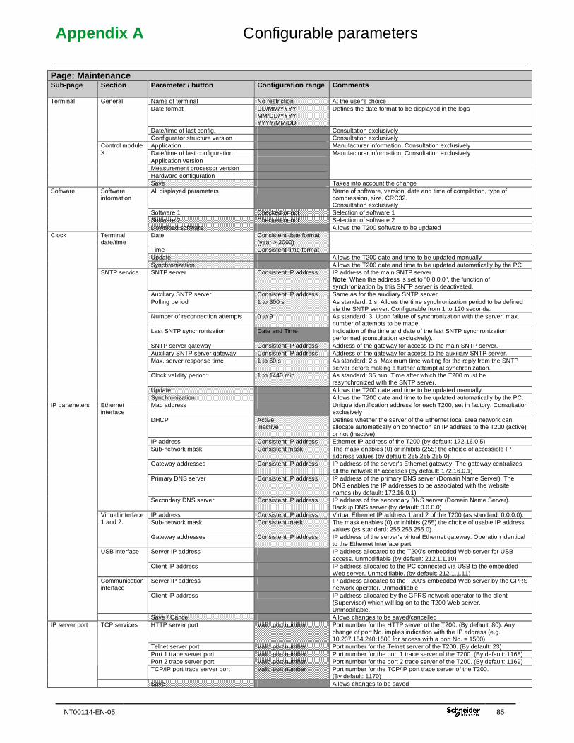
Appendix A Configurable parameters
NT00114-EN-05 85
Page: Maintenance Sub-page Section Parameter / button Configuration range Comments
Name of terminal No restriction At the user's choice Date format DD/MM/YYYY
MM/DD/YYYY YYYY/MM/DD
Defines the date format to be displayed in the logs
Date/time of last config. Consultation exclusively
General
Configurator structure version Consultation exclusively Application Manufacturer information. Consultation exclusively Date/time of last configuration Application version Measurement processor version Hardware configuration
Manufacturer information. Consultation exclusively
Terminal
Control module X
Save Takes into account the change All displayed parameters Name of software, version, date and time of compilation, type of
compression, size, CRC32. Consultation exclusively
Software 1 Checked or not Selection of software 1 Software 2 Checked or not Selection of software 2
Software Software information
Download software Allows the T200 software to be updated Date Consistent date format
(year > 2000)
Time Consistent time format Update Allows the T200 date and time to be updated manually
Terminal date/time
Synchronization Allows the T200 date and time to be updated automatically by the PC SNTP server Consistent IP address IP address of the main SNTP server.
Note : When the address is set to "0.0.0.0", the function of synchronization by this SNTP server is deactivated.
Auxiliary SNTP server Consistent IP address Same as for the auxiliary SNTP server. Polling period 1 to 300 s As standard: 1 s. Allows the time synchronization period to be defined
via the SNTP server. Configurable from 1 to 120 seconds. Number of reconnection attempts 0 to 9 As standard: 3. Upon failure of synchronization with the server, max.
number of attempts to be made. Last SNTP synchronisation Date and Time Indication of the time and date of the last SNTP synchronization
performed (consultation exclusively). SNTP server gateway Consistent IP address Address of the gateway for access to the main SNTP server. Auxiliary SNTP server gateway Consistent IP address Address of the gateway for access to the auxiliary SNTP server. Max. server response time 1 to 60 s As standard: 2 s. Maximum time waiting for the reply from the SNTP
server before making a further attempt at synchronization. Clock validity period: 1 to 1440 min. As standard: 35 min. Time after which the T200 must be
resynchronized with the SNTP server. Update Allows the T200 date and time to be updated manually.
Clock
SNTP service
Synchronization Allows the T200 date and time to be updated automatically by the PC. Mac address Unique identification address for each T200, set in factory. Consultation
exclusively DHCP Active
Inactive Defines whether the server of the Ethernet local area network can allocate automatically on connection an IP address to the T200 (active) or not (inactive)
IP address Consistent IP address Ethernet IP address of the T200 (by default: 172.16.0.5) Sub-network mask Consistent mask The mask enables (0) or inhibits (255) the choice of accessible IP
address values (by default: 255.255.255.0) Gateway addresses Consistent IP address IP address of the server's Ethernet gateway. The gateway centralizes
all the network IP accesses (by default: 172.16.0.1) Primary DNS server Consistent IP address IP address of the primary DNS server (Domain Name Server). The
DNS enables the IP addresses to be associated with the website names (by default: 172.16.0.1)
Ethernet interface
Secondary DNS server Consistent IP address IP address of the secondary DNS server (Domain Name Server). Backup DNS server (by default: 0.0.0.0)
IP address Consistent IP address Virtual Ethernet IP address 1 and 2 of the T200 (as standard: 0.0.0.0). Sub-network mask Consistent mask The mask enables (0) or inhibits (255) the choice of usable IP address
values (as standard: 255.255.255.0).
Virtual interface 1 and 2:
Gateway addresses Consistent IP address IP address of the server's virtual Ethernet gateway. Operation identical to the Ethernet Interface part.
Server IP address IP address allocated to the T200's embedded Web server for USB access. Unmodifiable (by default: 212.1.1.10)
USB interface
Client IP address IP address allocated to the PC connected via USB to the embedded Web server. Unmodifiable. (by default: 212.1.1.11)
Server IP address IP address allocated to the T200's embedded Web server by the GPRS network operator. Unmodifiable.
Communication interface
Client IP address IP address allocated by the GPRS network operator to the client (Supervisor) which will log on to the T200 Web server. Unmodifiable.
IP parameters
Save / Cancel Allows changes to be saved/cancelled HTTP server port Valid port number Port number for the HTTP server of the T200. (By default: 80). Any
change of port No. implies indication with the IP address (e.g. 10.207.154.240:1500 for access with a port No. = 1500)
Telnet server port Valid port number Port number for the Telnet server of the T200. (By default: 23) Port 1 trace server port Valid port number Port number for the port 1 trace server of the T200. (By default: 1168) Port 2 trace server port Valid port number Port number for the port 2 trace server of the T200. (By default: 1169)
TCP services
TCP/IP port trace server port Valid port number Port number for the TCP/IP port trace server of the T200. (By default: 1170)
IP server port
Save Allows changes to be saved
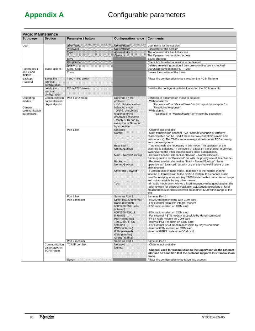
Appendix A Configurable parameters
86 NT00114-EN-05
Page: Maintenance Sub-page Section Parameter / button Configuration range Comments
User name No restriction User name for the session Password No restriction Password for the session Type Administrator
Operator The Administrator has full access The Operator has restricted access
Save Saves changes Recycle bin Check box to select a session to be deleted
User
Delete Deletes an existing session if the corresponding box is checked Start / Stop Start/Stop frame motion PC – T200 Port traces 1
and 2 and TCP/IP
Trace options Erase Erases the content of the trace
Backup / Restoral
Saves the terminal configuration
T200 -> PC arrow Allows the configuration to be saved on the PC in file form
Loads the terminal configuration
PC -> T200 arrow Enables the configuration to be loaded on the PC from a file
Port 1 or 2 mode Depends on the protocol: - IEC: Unbalanced or balanced mode - DNP3: Unsolicited response or No unsolicited response - Modbus: Report by exception or No report by exception
Definition of transmission mode to be used: - Without alarms:
"Unbalanced" or "Master/Slave" or "No report by exception" or "Unsolicited response".
- With alarms: "Balanced" or "Master/Master" or "Report by exception".
Port 1 link Not used Normal Balanced – Normal/Backup Main – Normal/Backup Backup – Normal/Backup Store and Forward Test
- Channel not available - Main transmission channel. Two "normal" channels of different characteristics can be used if there are two control PCs (main and maintenance). The T200 cannot manage simultaneous TCDs coming from the two systems. - Two channels are necessary in this mode. The operation of the channels is balanced. In the event of a fault on the channel in service, switchover to the other channel takes place automatically. - Requires another channel as "Backup – Normal/Backup". Same operation as "Balanced" but with the priority use of this channel. - Requires another channel as "Main – Normal/Backup". Same operation as "Balanced" but with use of this channel if failure of the Main channel. - Function used in radio mode. In addition to the normal channel function of transmission to the SCADA system, this channel is also used for relaying to an auxiliary T200 located within transmission range and not accessible by any other means. - (in radio mode only). Allows a fixed frequency to be generated on the radio network for antenna installation adjustment operations or level measurements on fields received on another T200 within range of the first.
Port 2 link Same as Port 1 Same as Port 1 Port 1 medium Direct RS232 (internal)
Radio (external) 600/1200 FSK radio (internal) 600/1200 FSK LL (internal) PSTN (external) 1200/2400 FFSK (internal) PSTN (internal) GSM (external) GSM (internal) GPRS (internal)
- RS232 modem integral with COM card - For external radio with integral modem - FSK radio modem on COM card - FSK radio modem on COM card - For external PSTN modem accessible by Hayes command - FFSK radio modem on COM card - Internal PSTN modem on COM card - For external GSM modem accessible by Hayes command - Internal GSM modem on COM card - Internal GPRS modem on COM card
Communication parameters on physical ports
Port 2 medium Same as Port 1 Same as Port 1 Communication parameters on TCP/IP ports
TCP/IP port link Not used Normal
- Channel not available
- Channel used for transmission to the Supervisor v ia the Ethernet interface on condition that the protocol supports t his transmission mode.
Operating modes General communication parameters
Save Allows the configuration to be taken into account
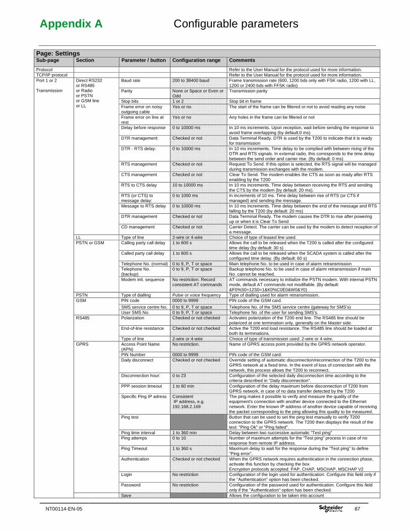
Appendix A Configurable parameters
NT00114-EN-05 87
Page: Settings Sub-page Section Parameter / button Configuration range Comments
Protocol Refer to the User Manual for the protocol used for more information. TCP/IP protocol Refer to the User Manual for the protocol used for more information.
Baud rate 200 to 38400 baud Frame transmission rate (600, 1200 bds only with FSK radio, 1200 with LL, 1200 or 2400 bds with FFSK radio)
Parity None or Space or Even or Odd
Transmission parity
Stop bits 1 or 2 Stop bit in frame Frame error on noisy outgoing cable
Yes or no The start of the frame can be filtered or not to avoid reading any noise
Frame error on line at rest
Yes or no Any holes in the frame can be filtered or not
Delay before response 0 to 10000 ms In 10 ms increments. Upon reception, wait before sending the response to avoid frame overlapping (by default:0 ms)
DTR management: Checked or not Data Terminal Ready. DTR is used by the T200 to indicate that it is ready for transmission
DTR - RTS delay: 0 to 10000 ms In 10 ms increments. Time delay to be complied with between rising of the DTR and RTS signals. In external radio, this corresponds to the time delay between the send order and carrier rise. (By default: 0 ms)
RTS management Checked or not Request To Send. If this option is selected, the RTS signal will be managed during transmission exchanges with the modem.
CTS management Checked or not Clear To Send. The modem enables the CTS as soon as ready after RTS enabling by the T200
RTS to CTS delay 10 to 10000 ms In 10 ms increments. Time delay between receiving the RTS and sending the CTS by the modem (by default: 20 ms).
RTS (or CTS) to message delay:
0 to 1000 ms In increments of 10 ms. Time delay between rise of RTS (or CTS if managed) and sending the message.
Message to RTS delay 0 to 10000 ms In 10 ms increments. Time delay between the end of the message and RTS falling by the T200 (by default: 20 ms)
DTR management Checked or not Data Terminal Ready. The modem causes the DTR to rise after powering up or when it is Clear To Send
Direct RS232 or RS485 or Radio or PSTN or GSM line or LL
CD management Checked or not Carrier Detect. The carrier can be used by the modem to detect reception of a message.
LL Type of line 2-wire or 4-wire Choice of type of leased line used. Calling party call delay 1 to 600 s Allows the call to be released when the T200 is called after the configured
time delay (by default: 30 s) Called party call delay 1 to 600 s Allows the call to be released when the SCADA system is called after the
configured time delay. (By default: 60 s) Telephone No. (normal) 0 to 9, P, T or space Main telephone No. to be used in case of alarm retransmission Telephone No. (backup)
0 to 9, P, T or space Backup telephone No. to be used in case of alarm retransmission if main No. cannot be reached.
PSTN or GSM
Modem init. sequence No restriction. Record consistent AT commands
AT commands necessary to initialize the PSTN modem. With internal PSTN mode, default AT commands not modifiable. (By default: &F0%S0=12S0=1&K0%C0E0&W0&Y0)
PSTN Type of dialling Pulse or voice frequency Type of dialling used for alarm retransmission. PIN code 0000 to 9999 PIN code of the GSM card.
SMS service centre No. 0 to 9, P, T or space Telephone No. of the SMS service centre (gateway for SMS's)
GSM
User SMS No. 0 to 9, P, T or space Telephone No. of the user for sending SMS's. Polarization Checked or not checked Activates polarization of the T200 end line. The RS485 line should be
polarized at one termination only, generally on the Master side. End-of-line resistance Checked or not checked Active the T200 end load resistance. The RS485 line should be loaded at
both its terminations.
RS485
Type of line 2-wire or 4-wire Choice of type of transmission used: 2-wire or 4-wire. Access Point Name (APN)
No restriction. Name of GPRS access point provided by the GPRS network operator.
PIN Number 0000 to 9999 PIN code of the GSM card. Daily disconnect Checked or not checked Override setting of automatic disconnection/reconnection of the T200 to the
GPRS network at a fixed time. In the event of loss of connection with the network, this process allows the T200 to reconnect.
Disconnection hour: 0 to 23 Configuration of the selected daily disconnection time according to the criteria described in "Daily disconnection".
PPP session timeout 1 to 60 min Configuration of the delay maximum before disconnection of T200 from GPRS network, in case of no data transfer detected by the T200
Specific Ping IP adress Consistent IP address, e.g. 192.168.2.169
The ping makes it possible to verify and measure the quality of the equipment's connection with another device connected to the Ethernet network. Enter the known IP address of another device capable of receiving the packet corresponding to the ping allowing this quality to be measured.
Ping test Button that can be used to set the ping test manually to verify T200 connection to the GPRS network. The T200 then displays the result of the test: "Ping Ok" or "Ping failed".
Ping time interval 1 to 360 min Delay between two successive automatic “Test ping” Ping attemps 0 to 10 Number of maximum attempts for the “Test ping” process in case of no
response from remote IP address. Ping Timeout 1 to 360 s Maximum delay to wait for the response during the “Test ping” to define
“Ping error”. Authentication Checked or not checked When the GPRS network requires authentication in the connection phase,
activate this function by checking the box. Encryption protocols accepted: PAP, CHAP, MSCHAP, MSCHAP V2
Login No restriction Configuration of the login used for authentication. Configure this field only if the "Authentication" option has been checked.
GPRS
Password No restriction Configuration of the password used for authentication. Configure this field only if the "Authentication" option has been checked.
Port 1 or 2 Transmission
Save Allows the configuration to be taken into account
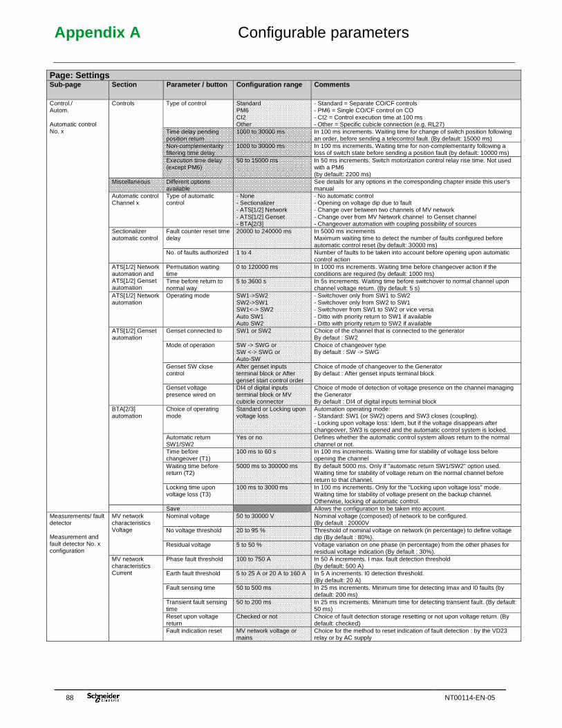
Appendix A Configurable parameters
88 NT00114-EN-05
Page: Settings Sub-page Section Parameter / button Configuration range Comments
Type of control Standard PM6 CI2 Other
- Standard = Separate CO/CF controls - PM6 = Single CO/CF control on CO - CI2 = Control execution time at 100 ms - Other = Specific cubicle connection (e.g. RL27)
Time delay pending position return
1000 to 30000 ms In 100 ms increments. Waiting time for change of switch position following an order, before sending a telecontrol fault. (By default: 15000 ms)
Non-complementarity filtering time delay
1000 to 30000 ms In 100 ms increments. Waiting time for non-complementarity following a loss of switch state before sending a position fault (by default: 10000 ms)
Controls
Execution time delay (except PM6)
50 to 15000 ms In 50 ms increments. Switch motorization control relay rise time. Not used with a PM6 (by default: 2200 ms)
Miscellaneous Different options available
See details for any options in the corresponding chapter inside this user's manual
Automatic control Channel x
Type of automatic control
- None - Sectionalizer - ATS[1/2] Network - ATS[1/2] Genset - BTA[2/3]
- No automatic control - Opening on voltage dip due to fault - Change over between two channels of MV network - Change over from MV Network channel to Genset channel - Changeover automation with coupling possibility of sources
Fault counter reset time delay
20000 to 240000 ms In 5000 ms increments Maximum waiting time to detect the number of faults configured before automatic control reset (by default: 30000 ms)
Sectionalizer automatic control
No. of faults authorized 1 to 4 Number of faults to be taken into account before opening upon automatic control action
Permutation waiting time
0 to 120000 ms In 1000 ms increments. Waiting time before changeover action if the conditions are required (by default: 1000 ms)
ATS[1/2] Network automation and ATS[1/2] Genset automation
Time before return to normal way
5 to 3600 s In 5s increments. Waiting time before switchover to normal channel upon channel voltage return. (By default: 5 s)
ATS[1/2] Network automation
Operating mode SW1->SW2 SW2->SW1 SW1<-> SW2 Auto SW1 Auto SW2
- Switchover only from SW1 to SW2 - Switchover only from SW2 to SW1 - Switchover from SW1 to SW2 or vice versa - Ditto with priority return to SW1 if available - Ditto with priority return to SW2 if available
Genset connected to SW1 or SW2 Choice of the channel that is connected to the generator By defaut : SW2
Mode of operation SW -> SWG or SW <-> SWG or Auto-SW
Choice of changeover type By default : SW -> SWG
Genset SW close control
After genset inputs terminal block or After genset start control order
Choice of mode of changeover to the Generator By defaut : After genset inputs terminal block
ATS[1/2] Genset automation
Genset voltage presence wired on
DI4 of digital inputs terminal block or MV cubicle connector
Choice of mode of detection of voltage presence on the channel managing the Generator By default : DI4 of digital inputs terminal block
Choice of operating mode
Standard or Locking upon voltage loss
Automation operating mode: - Standard: SW1 (or SW2) opens and SW3 closes (coupling). - Locking upon voltage loss: Idem, but if the voltage disappears after changeover, SW3 is opened and the automatic control system is locked.
Automatic return SW1/SW2
Yes or no Defines whether the automatic control system allows return to the normal channel or not.
Time before changeover (T1)
100 ms to 60 s In 100 ms increments. Waiting time for stability of voltage loss before opening the channel
Waiting time before return (T2)
5000 ms to 300000 ms By default 5000 ms. Only if "automatic return SW1/SW2" option used. Waiting time for stability of voltage return on the normal channel before return to that channel.
BTA[2/3] automation
Locking time upon voltage loss (T3)
100 ms to 3000 ms In 100 ms increments. Only for the "Locking upon voltage loss" mode. Waiting time for stability of voltage present on the backup channel. Otherwise, locking of automatic control.
Control./ Autom. Automatic control No. x
Save Allows the configuration to be taken into account. Nominal voltage 50 to 30000 V Nominal voltage (composed) of network to be configured.
(By default : 20000V No voltage threshold 20 to 95 % Threshold of nominal voltage on network (in percentage) to define voltage
dip (By default : 80%).
MV network characteristics Voltage
Residual voltage 5 to 50 % Voltage variation on one phase (in percentage) from the other phases for residual voltage indication (By default : 30%).
Phase fault threshold 100 to 750 A In 50 A increments. I max. fault detection threshold (by default: 500 A)
Earth fault threshold 5 to 25 A or 20 A to 160 A In 5 A increments. I0 detection threshold. (By default: 20 A)
Fault sensing time 50 to 500 ms In 25 ms increments. Minimum time for detecting Imax and I0 faults (by default: 200 ms)
Transient fault sensing time
50 to 200 ms In 25 ms increments. Minimum time for detecting transient fault. (By default: 50 ms)
Reset upon voltage return
Checked or not Choice of fault detection storage resetting or not upon voltage return. (By default: checked)
Measurements/ fault detector Measurement and fault detector No. x configuration
MV network characteristics Current
Fault indication reset MV network voltage or mains
Choice for the method to reset indication of fault detection : by the VD23 relay or by AC supply
Appendix A Configurable parameters
NT00114-EN-05 89
Page: Settings Sub-page Section Parameter / button Configuration range Comments
MV network characteristics Current
Detector reset time delay
15 to 120 min. In 15 min. increments. Time for fault detection storage resetting (by default: 120 min.)
Power supply functions
AC supply OFF delay 0 to 21600 s In 15 min. increments. Time delay for filtering the power supply undervoltage signal supplied by the power supply card. Allows indication of extended mains power supply failure. (By default: 7200 s)
Measurements/ fault detector Measurement and fault detector No. x configuration
Save Allows the configuration to be taken into account Variable name No restriction Name given to variable. Type Single or double TCD = double control only Access Administrator
Operator Monitoring
Access right for this variable. The variable will be readable or modifiable depending on the type of access configured and the associated access rights.
Order Reverse or normal The reverse choice reverses the order of the control bits for the TCD and the double telesignal (TSD) in the protocol frame to the Supervisor. E.g.: TCD and TSD on normal: bit 1 = opening, bit 2 = closing TCD and TSD on reverse: bit 1 = closing, bit 2 = opening (By default: Normal)
Class (Complete list of all classes defined)
Allows a variable to be assigned to an existing class.
Logical address TCD internal No. assigned automatically by the T200 (unmodifiable). Internal address Address for the COM-CPU internal Modbus link (unmodifiable). Associated logical address TS
TSD1 to TSD40 or none No. of the TSD associated with the TCD used by the T200 for reading the state.
General parameters
External address Format 'x' (e.g. 1) for all protocols except: - Modbus: 'x,x' (word, bit) - DNP3: 'x,x' (word, class)
External address used for retransmission of this TCD variable in the protocol link to the Supervisor.
Save Allows the configuration to be taken into account
Variable configuration Control configuration
Cancel Enables return to the preceding configuration Variable name No restriction Name given to variable. Type Single or double TSD = double information
TSS = single information Logical address TSD internal No. assigned automatically by the T200 (unmodifiable). Class (Complete list of all
classes) Allows a variable to be assigned to an existing class.
Access Administrator Operator Monitoring
Access right for this variable. The variable will be readable or modifiable depending on the type of access configured and the associated access rights.
Internal address Address for the COM-CPU internal Modbus link (unmodifiable). External address Format 'x' (e.g. 2) External address used by SCADA for this variable State definition: Active (1)
No restriction Name displayed for an active state of the variable
State colour: Active (1)
Black, blue, green or red colour
Display colour for an active state of the variable
State definition: Inactive (0)
No restriction Name displayed for an inactive state of the variable
State colour: Inactive (0)
Black, blue, green or red colour
Display colour for an inactive state of the variable
Other state: Undefined
No restriction Name displayed for an undefined state of the variable (only with TSD and not with TSS)
Global parameters
State colour: Undefined
Black, blue, green or red colour
Display colour for an undefined state of the variable (only with TSD and not with TSS)
Enable Checked or not Enabling of the record or not upon change of state of this variable in the event log
Upon any change of state (TSD) or upon active (TSS)
Checked or not Saving of the event upon any change of state of the variable (TSD) or upon appearance of the active state (TSS).
Recording configuration
Upon loss of closing (TSD) or upon inactive (TSS)
Checked or not Saving of the event upon disappearance of the closed state of the variable (TSD) or upon appearance of the inactive state (TSS).
Enable Checked or not Enabling of the alarm or not upon change of state of this variable and saving in the alarm log.
Upon any change of state (TSD) or upon active (TSS)
Checked or not Activation of the alarm and saving of alarm upon any change of state of the variable (TSD) or upon appearance of the active state (TSS)
Upon loss of closing (TSD) or upon inactive (TSS)
Checked or not Activation of the alarm and saving of alarm upon disappearance of the closed state of the variable (TSD) or upon appearance of the inactive state (TSS).
Alarm level Scada + sms Scada sms
Several possible actions in the event of a retransmission of alarm depending on the defined level.
Time-delayed alarm Checked or not Activates a time delay before sending the alarm. Delay value 0 to 99 Number of hours, minutes or seconds for the delay before sending the
alarm to the SCADA
Alarm configuration
Hours or Minutes or Seconds
Checked according to choice
Choice of unit for the value of the alarm delay
Save Allows the configuration to be taken into account
Variable configuration Indications configuration
Cancel Enables return to the preceding configuration
Appendix A Configurable parameters
90 NT00114-EN-05
Page: Settings Sub-page Section Parameter / button Configuration range Comments
Variable name No restriction Name given to variable. Correction coefficient Direct or raw or
Direct/10 to direct/10000 or Direct*10 to direct*10000
Definition of a coefficient of multiplication to be applied to the measurement variable for its correct display in the monitoring page. Allows display in the correct format relative to the real size By default for T200 series 3: current = direct/10 and voltage = direct By default for T200 series 1 or 2 or L500 compatibility: current = direct and voltage = direct*100
Logical address TM internal No. assigned automatically by the T200 (unmodifiable). Class (Complete list of all
classes) Allows a variable to be assigned to an existing class.
Access Administrator Operator Monitoring
Access right for this variable. The variable will be readable or modifiable depending on the type of access configured and the associated access rights.
Internal address Address for the COM-CPU internal Modbus link (unmodifiable). External address (SCADA) Format 'x' (e.g. 2) External address used by SCADA for this variable Unit No restriction Unit for display of the variable Max. value Integer Maximum value that can be taken in practice by the measurement value.
NB: The value configured influences the precision of the measurement.
General parameters
Min. value Integer Minimum value that can be taken in practice by the measurement value. NB: The value configured influences the precision of the measurement.
Recording Checked or not Enabling of regular saving of the measurement in the measurement log or not.
Period 15 min., 30 min. or 1 h Measurement recording period Type Averaged or sampled Way of calculating the measurement for recording in the measurements log Event Checked or not Enabling of regular saving of the measurement in the protocol event stack
or not. Call Checked or not Enabling of regular sending of the alarm to SCADA and saving in the alarm
log or not.
Regular processing
Period 15 min., 30 min. or 1 h Event or call saving period. Recording Checked or not Enabling of saving of the measurement in the measurements log or not
upon exceeding threshold Event Checked or not Enabling of saving or not upon exceeding the measurement threshold in the
protocol event stack. Call Checked or not Enabling of sending of the alarm to SCADA and saving in the alarm log or
not upon exceeding threshold. High threshold Checked or not Enabling of high threshold or not Low threshold Checked or not Enabling of low threshold or not High threshold value No restriction Value for enabling exceeding of the high measurement threshold
Processing on threshold
Low threshold value No restriction Value for enabling exceeding of the low measurement threshold Recording Checked or not Enabling of recording of the measurement in the measurements log or not
through variation Event Checked or not Enabling of regular saving or not upon variation of the measurement in the
protocol event stack. Call Checked or not Enabling of sending of the alarm to SCADA and saving in the alarm log or
not following measurement variation. Method Fixed or percentage Fixed: A fixed change in the value of the variable results in an associated
processing operation (saving, alarm). Percentage: A change in percentage of the variable results in an associated processing operation.
Value 0 to Max. scale value Fixed value or % measurement variation for dead band processing
Dead band
Minimum change 0 to Max. scale value Minimum change in the measurement variation for the dead band to be processed
Active maximum Checked or not Recording or not of the maximum measurement reached over the period configured
Active minimum Checked or not Recording or not of the minimum measurement reached over the period configured.
Min. and Max. recording
Period 1, 7 or 14 days Calculation period for min. and max. value Save Allows the configuration to be taken into account
Variable configuration Measurement configuration
Cancel Enables return to the preceding configuration
Appendix A Configurable parameters
NT00114-EN-05 91
Page: Settings Sub-page Section Parameter / button Configuration range Comments
Variable name No restriction Name given to variable. Correction coefficient Direct or raw or
Direct/10 to 10000 or Direct*10 to 10000
Definition of a coefficient of multiplication to be applied to the counter variable for its correct display in the monitoring page. Allows display in the correct format relative to the real size By default for T200 series 3: current = direct/10 and voltage = direct By default for T200 series 1 or 2 or L500 compatibility: current = direct and voltage = direct*100
Logical address CNT internal No. assigned automatically by the T200 (unmodifiable). Class (Complete list of all
classes) Allows a variable to be assigned to an existing class.
Access Administrator Operator Monitoring
Access right for this variable. The variable will be readable or modifiable depending on the type of access configured and the associated access rights.
Internal address Address for the COM-CPU internal Modbus link (unmodifiable). External address (SCADA)
Format 'x' (e.g. 2) External address used by SCADA for this variable
Unit No restriction Unit for display of the variable Max. value Integer Maximum value that can be taken in practice by the counter value.
NB: The value configured influences the precision of the counter.
General parameters
Min. value Integer Minimum value that can be taken in practice by the counter value. NB: The value configured influences the precision of the counter.
Type of object Digital or Analogue Selection of the variable type on which the counter is incremented Object TSSxx or Dixx or TMxx or
AIxx Name of the variable to which the counter is assigned
Counting method Pulse counter - Time counter - Integrating meter
Depending on the type of object, the methods displayed are as follows: • For a DI type variable: - Pulse counter. - Time counter. - Integrating meter. • For an AI/AO type variable: - Integrating meter. - “Mean” counter.
Pulse width 0 to 2000 ms In 10 ms increments. Pulse length (in ms) after which the T200 will consider a state as high.
Inhibition after reset 0 to 2000 ms In 10 ms increments. Period during which the T200 inhibits pulse detection after zero crossing by the variable. This filter makes it possible to avoid possible rebounds in the event of a return to zero.
Integration period 0 to 86400 s Useful period of the measurement in the case of an integrating meter (DI type variable) or mean (AI type variable).
Conversion factor 0 to 10000 Used in the case of a pulse counter. Weight of the pulse sent. With each pulse sent, the counter value is incremented in accordance with the conversion factor.
Internal counting
Active state Low or High Field used only in the case of a time counter. State of the variable (high or low) which activates the time counter.
Recording Checked or not Enabling of regular recording of the counter in the measurement log or not.
Event Checked or not Enabling of regular saving of the counter in the protocol event stack or not.
Call Checked or not Enabling of regular sending of the alarm to SCADA and saving in the alarm log or not.
Regular processing
Period 15 min., 30 min. or 1 h Counter recording period. Recording Checked or not Enabling of recording of the counter in the measurements log or not upon
exceeding threshold Event Checked or not Enabling of saving or not upon exceeding the counter threshold in the
protocol event stack. Call Checked or not Enabling of sending of the alarm to SCADA and saving in the alarm log
or not upon exceeding threshold.
Processing on threshold
Value No restriction Value for enabling exceeding of the high counter threshold. Recording Checked or not Enabling of saving or not upon counter variation in the measurement log. Event Checked or not Enabling of saving or not upon counter variation in the protocol event
stack. Call Checked or not Enabling of sending of the alarm to SCADA and saving in the alarm log
or not following counter variation.
Dead band
Value as % 0 to 255 % variation of the counter for the dead band criterion. Save Allows the configuration to be taken into account.
Variable configuration Counters
Cancel Enables return to the preceding configuration. Recycle bin Checked or not Selection of class to be deleted or not Monitoring Checked or not Selection or not of class display in the Monitoring page Class name No restriction Class name to be displayed Save Allows a modification or a creation to be recorded for each class
Class management
Delete Allows a class that has been selected earlier to be deleted
Appendix B General characteristics
92 NT00114-EN-05
7 Appendix B - General characteristics Power supply AC supply
Characteristics 230 Vac - 50 Hz, 120 VA Protected by HRC fuse of 4 A rating, type gF Permissible mains voltage: 90 V to 270 Vac (43 V and 57 V on option).
Charger 12 V / 7 A
Rack power supply 12 Vdc (10.8 V to 14.8 V). Protected by a 0.8 A fuse Telecommunications 12 Vdc (10.8 V to 14.8 V) max. 1 A Protection if consumption > 1.3 A for more than
3 min. Power supply
48 V or 24 V motorization 48 Vdc (44.8 V to 59 V) max. 6 A for 12 s and 15 A, 50 ms Protected by 5-A fuse. Permanent consumption tolerated on 48 V for auxiliary equipment: 90 mA
Type Sealed lead maintenance-free type
Charging time 10 h to 24 h
Charger capacity 12 Vdc - 24 Ah
Battery life from –15°C to +55°C Up to 16 h + 10 o pen/close (O/F) cycles
Monitoring Total discharge, periodic tests every 12 hours (10A during 100 ms). Successful test if U Bat.> 11,2V, at the end of the test. Two consecutive unsuccessful tests generate battery fault
Battery
Lifetime at 20°C 10 years
Characteristics Telecontrols (TCD) 1 to 4 channels (8- to 16-channel option) Opening/closing orders controlled by +V
(or 0V) polarity for a duration of 3 s, with fuse-protected outputs. Double telesignals (TSD) As for TCD. Indication of open/closed positions, "Locked" (earthing switch).
Input/output capacity
Indication inputs 6 digital inputs per Control module, controlled by 0V polarity. AC supply input Insulation (50 Hz/1 min.): 10 kV Surge (1.2/50 µs): 20 kV
Dielectric Toroid input Insulation (50 Hz/1 min.): 2 kV Surge (1.2/50 µs): 5 kV
Electrostatic discharges IEC 61 000-4-2 Level 3 : 6 kV contact Radiated electromagnetic field IEC 61 000-4-3 80 MHz – 1 GHz – 10 V/m
Rapid transients IEC 61 000-4-4 Level 4 : 4 kV (power supply, toroids), 2 kV (other circuits)
Surge wave immunity CEI 61 000-4-5 2KV common mode , 1 KV differential mode
Radio frequency on FSM IEC 61 000-4-6 0,15 MHz à 80 MHz – 10 Vac
50 Hz magnetic fields IEC 61 000-4-8 30 A/m (T200I), 100A/m (T200E)
Pulse magnetic fields immunity CEI 61 000-4-9 1000 A/m peak
Electromagnetic
Ring or damped oscillatory waves immunity
CEI 61 000-4-12 2,5 KV common mode, 1KV differential mode
Temperature – 15 °C to + 55 °C
Relative humidity IEC 60 68-2-3 93 % at 40 °C
Salt spray test IEC 60 68-2-11 192 h +35°c (T200I) , 336h +35°c (T200E) Climatique
Storage temperature IEC 60 68-2-14 – 25 °C à + 70 °C
Enclosure material 10 to 500 Hz ; 1 g or 0,30 mn peak à peak
Vibrations IEC 60 68-2-6 10 to 500 Hz ; 1 g or 0,30 mn peak à peak
Dimensions (T200I 2 voies) H x W x D 670 mm x 310 mm x 335 mm (T200I), 465mm x 380 mm, 275mm (T200E)
Weight 50 kg (T200I), 40 Kg (T200E)
Mechanical
Protection IEC 60 529 IP33 (T200I), IP54 (T200E)
Options Internal fault detector
Capacity 4 per T200 Control module
Type Constant time current sensor Phase-to-phase fault threshold 100 to 750 A Earth fault threshold Configurable from 20 to 160 A or 5 to 20 A Fault duration 50 to 500 ms Reset By voltage return, by time delay or via an external loop
Current
Phase current measurement Yes Type Single-phase or three-phase Power off threshold 20% to 95% of rated voltage Residual voltage threshold 5% to 50% of rated voltage
Voltage
Mains voltage measurement Yes I and U measurement 3 % Measurement
accuracy Fault detector 3 %
External fault detector
Capacity 4 per T200 Control module
SEC function Opens after a failed reset Opens in the first or second slow reset voltage dip
ATS function Source changeover switch Configurable delay time and return time
BTA function Source changeover switch with coupling Configurable delay time, return time and time for locking upon voltage loss.
GPS (option) Time synchronization by satellites Accuracy of time setting: 5 ms on average, 50 ms max.
SNTP (option)p Time synchronization by Internet Accuracy of time setting: 1 second on average.
Cubicle connection
Type of connection Polarized connectors.

Easergy T200I Personnal notes
NT00114-EN-05 93

Easergy T200I Personnal notes
94 NT00114-EN-05

Easergy T200I Personnal notes
NT00114-EN-05 95

Schneider Electric Industries SAS Schneider Electric Telecontrol 839 chemin des Batterses Z.I. Ouest 01700 St Maurice de Beynost Tel : +33 (0)4 78 55 13 13 Fax : +33 (0)4 78 55 50 00 http://www.schneider-electric.com E-mail : [email protected]
As standards, specifications and designs change from time to time, please ask for confirmation of the information given in this publication.
NT00114-EN-05 12/2009
Publication: Schneider Electric Telecontrol - Made in France Production: Schneider Electric Telecontrol - Made in France Printing: Schneider Electric Telecontrol - Made in France