Embed Size (px)
Citation preview
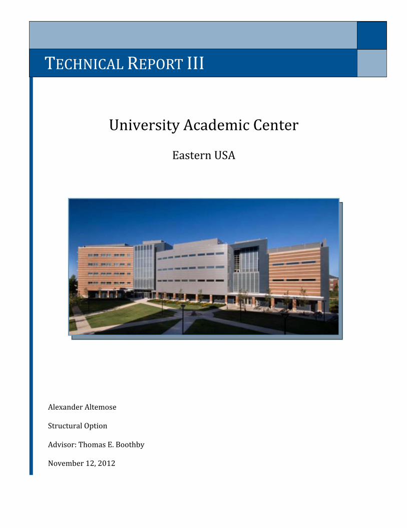
University Academic Center
Eastern USA Alexander Altemose Structural Option Advisor: Thomas E. Boothby November 12, 2012
TECHNICAL REPORT III
University Academic Center 2
Technical Report III Structural Option Alexander Altemose
Table of Contents Executive Summary 3
Introduction 4
Structural Overview 5
Foundation 5
Floor and Roof System 7
Framing System 8
Lateral System 8
Design Codes 9
Design Loads 10
Dead Loads 10
Live Loads 10
Snow Loads 11
Wind Loads 12
Seismic Loads 15
Load Combinations 16
Wind Load Cases 18
Seismic Load Cases 19
Overturning Moment 19
ETABS Model 20
Relative Stiffness 21
Torsional Effects 23
Story Drift and Displacement 24
Member Checks 24
Conclusion 25
Appendix A: Gridline layout 26
Appendix B: Braced Frames 27
Appendix C: Hand Calculations 29
Appendix D: Member Checks 38
University Academic Center 3
Technical Report III Structural Option Alexander Altemose
Executive Summary
This report focused on the lateral force resisting system used in the University
Academic Center. The lateral system consists of 15 total frames, most concentrically braced
and some moment frames. Analysis of this system was done using ETABS modeling to
facilitate calculations. Data for torsion, story drift, and displacements was interpreted from
the ETABS results and compared to current code provisions.
University Academic Center is an asymmetric building with multiple roof levels
stepping down from a five story office wing to the single story library area. This variation in
form provides an appealing architecture, but complicates the structural design, creating
eccentricities and requiring more consideration into framing to minimize displacements.
The framing for this building is a structural composite steel system of mostly wide
flange members with HSS diagonal bracing members in the lateral resisting system. Lateral
forces are resisted by a combination of 15 braced frames spread throughout the building
with the majority located in the central classroom wing. Due to the rotation of several of
the braced frames hand calculations would prove more difficult so computer modeling
software was used in a large part of this report.
Preliminary determination of load values was shown including snow and drift loads,
dead loads, live loads, wind loads in generalized N-S and E-W directions, and seismic loads.
The lateral loads were then input into the ETABS model to analyze maximum cases in story
drift and overall displacements as well as torsional effects on the building.
Story drifts and displacements were all determined to be within code limitations
with maximum drift and displacements occurring under wind case 3 loading. Maximum
displacement occurred in an E-W shift of 0.9722 in at the 5th floor roof. Maximum story
drift also occurred in this direction at the ground floor with a story drift of 0.2598 in.
ETABS output showed a large eccentricity resulting in center of mass and center of
rigidity displacement on all levels in the range of 20-40 feet on average. This was checked
with quick hand calculations and assumed accurate. Such an eccentricity results in high
torsional effects which could be easily seen in the ETABS model animation. Despite these
rotations University Academic Center still maintains enough rigidity to stay within code
limitations for displacements.
Member checks were also done to verify individual members were not overstressed
in the model assumptions. Those members checked remained stable based on loading
determined by ETABS output, further validating the results of this study.
University Academic Center 4
Technical Report III Structural Option Alexander Altemose
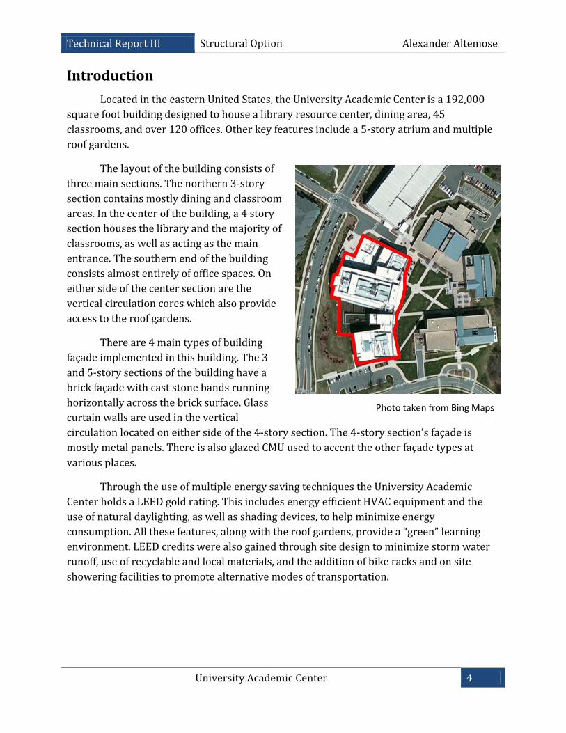
Photo taken from Bing Maps
Introduction
Located in the eastern United States, the University Academic Center is a 192,000
square foot building designed to house a library resource center, dining area, 45
classrooms, and over 120 offices. Other key features include a 5-story atrium and multiple
roof gardens.
The layout of the building consists of
three main sections. The northern 3-story
section contains mostly dining and classroom
areas. In the center of the building, a 4 story
section houses the library and the majority of
classrooms, as well as acting as the main
entrance. The southern end of the building
consists almost entirely of office spaces. On
either side of the center section are the
vertical circulation cores which also provide
access to the roof gardens.
There are 4 main types of building
façade implemented in this building. The 3
and 5-story sections of the building have a
brick façade with cast stone bands running
horizontally across the brick surface. Glass
curtain walls are used in the vertical
circulation located on either side of the 4-story section. The 4-story section’s façade is
mostly metal panels. There is also glazed CMU used to accent the other façade types at
various places.
Through the use of multiple energy saving techniques the University Academic
Center holds a LEED gold rating. This includes energy efficient HVAC equipment and the
use of natural daylighting, as well as shading devices, to help minimize energy
consumption. All these features, along with the roof gardens, provide a “green” learning
environment. LEED credits were also gained through site design to minimize storm water
runoff, use of recyclable and local materials, and the addition of bike racks and on site
showering facilities to promote alternative modes of transportation.
University Academic Center 5
Technical Report III Structural Option Alexander Altemose
Drawings provided by Skanska
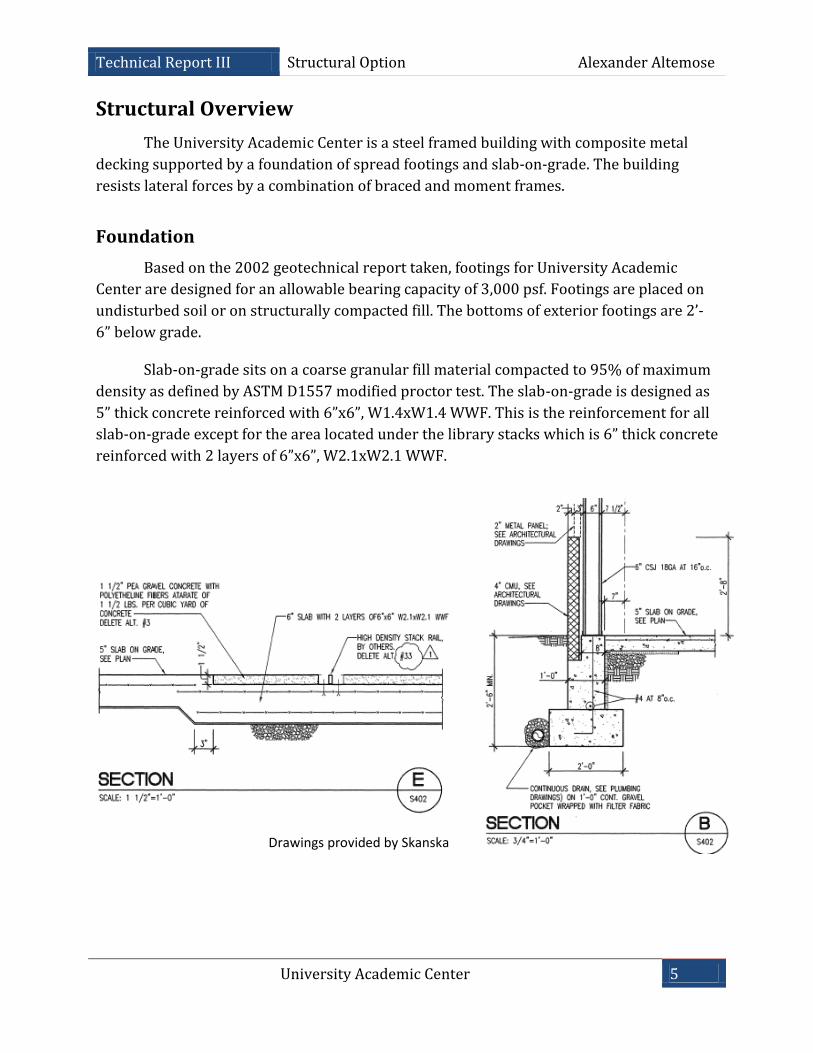
Structural Overview
The University Academic Center is a steel framed building with composite metal
decking supported by a foundation of spread footings and slab-on-grade. The building
resists lateral forces by a combination of braced and moment frames.
Foundation
Based on the 2002 geotechnical report taken, footings for University Academic
Center are designed for an allowable bearing capacity of 3,000 psf. Footings are placed on
undisturbed soil or on structurally compacted fill. The bottoms of exterior footings are 2’-
6” below grade.
Slab-on-grade sits on a coarse granular fill material compacted to 95% of maximum
density as defined by ASTM D1557 modified proctor test. The slab-on-grade is designed as
5” thick concrete reinforced with 6”x6”, W1.4xW1.4 WWF. This is the reinforcement for all
slab-on-grade except for the area located under the library stacks which is 6” thick concrete
reinforced with 2 layers of 6”x6”, W2.1xW2.1 WWF.
University Academic Center 6
Technical Report III Structural Option Alexander Altemose
Drawings provided by Skanska
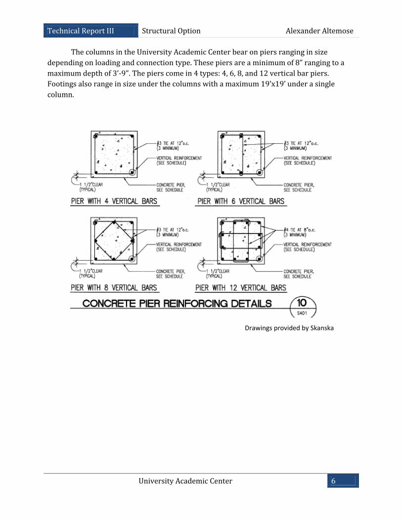
The columns in the University Academic Center bear on piers ranging in size
depending on loading and connection type. These piers are a minimum of 8” ranging to a
maximum depth of 3’-9”. The piers come in 4 types: 4, 6, 8, and 12 vertical bar piers.
Footings also range in size under the columns with a maximum 19’x19’ under a single
column.
University Academic Center 7
Technical Report III Structural Option Alexander Altemose
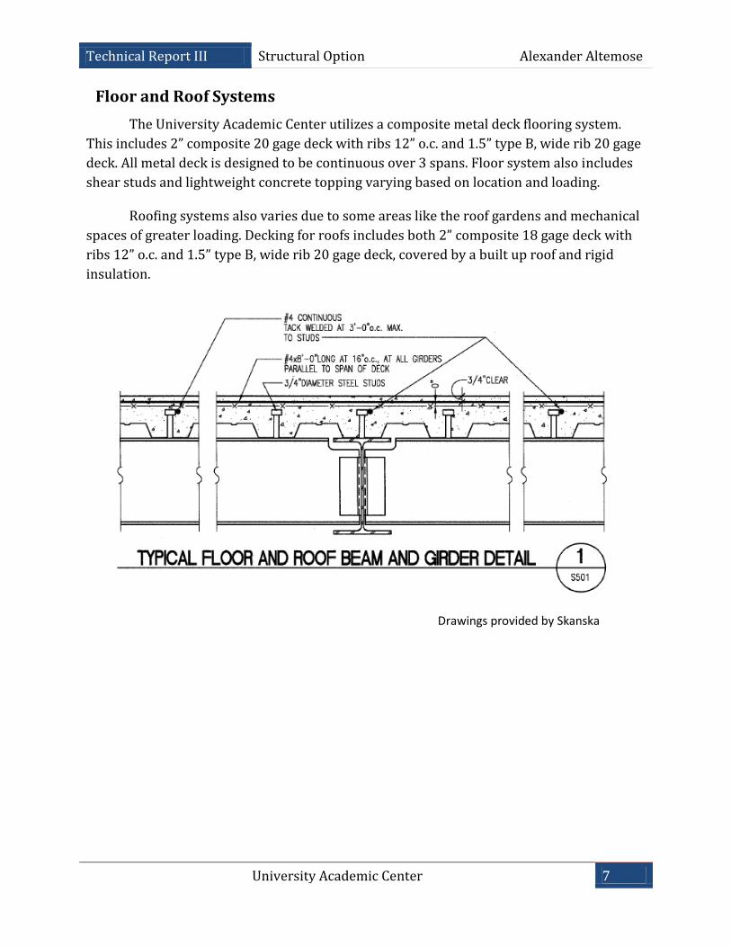
1Floor and Roof Systems
The University Academic Center utilizes a composite metal deck flooring system.
This includes 2” composite 20 gage deck with ribs 12” o.c. and 1.5” type B, wide rib 20 gage
deck. All metal deck is designed to be continuous over 3 spans. Floor system also includes
shear studs and lightweight concrete topping varying based on location and loading.
Roofing systems also varies due to some areas like the roof gardens and mechanical
spaces of greater loading. Decking for roofs includes both 2” composite 18 gage deck with
ribs 12” o.c. and 1.5” type B, wide rib 20 gage deck, covered by a built up roof and rigid
insulation.
Drawings provided by Skanska
University Academic Center 8
Technical Report III Structural Option Alexander Altemose
Drawings provided by Skanska
Framing System
The framing system for the University Academic Center includes C-shapes, HSS
members, and Wide Flange members with the majority being W-shapes. Gridlines are set at
multiple angles with bay sizes varying throughout the building. Areas with consistent
framing between floors are located in the classroom wing in the central section of the
building and the office spaces on the south side. The gravity system transfers vertical loads
due to dead, live, and snow loading across a floor or roof deck, into beams and girders, and
is take as axial force in columns to the foundation.
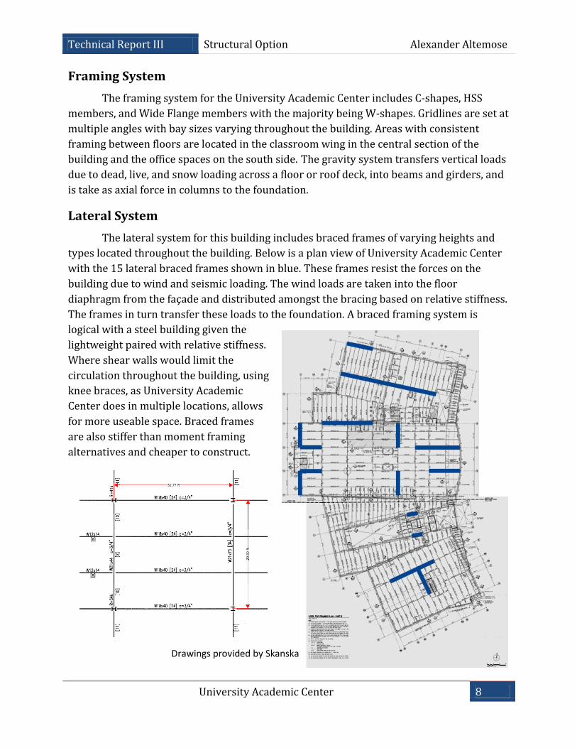
Lateral System
The lateral system for this building includes braced frames of varying heights and
types located throughout the building. Below is a plan view of University Academic Center
with the 15 lateral braced frames shown in blue. These frames resist the forces on the
building due to wind and seismic loading. The wind loads are taken into the floor
diaphragm from the façade and distributed amongst the bracing based on relative stiffness.
The frames in turn transfer these loads to the foundation. A braced framing system is
logical with a steel building given the
lightweight paired with relative stiffness.
Where shear walls would limit the
circulation throughout the building, using
knee braces, as University Academic
Center does in multiple locations, allows
for more useable space. Braced frames
are also stiffer than moment framing
alternatives and cheaper to construct.
University Academic Center 9
Technical Report III Structural Option Alexander Altemose
Codes and Standards
As Designed:
2000 ICC International Building Code
2000 ICC International Mechanical Code
2000 ICC International Plumbing Code
2000 ICC International Fuel-Gas Code
2000 ICC International Fire Code
2000 ICC International Energy Conservation Code
2000 NFPA Life Safety Code
2000 Americans with Disabilities Act – Accessibility Code
1999 National Electrical Code
AIC 318 “Building Code Requirements for Structural Concrete”
AIC 530 “Building Code Requirements for Masonry Structures”
AISC Manual of Steel Construction (locally approved edition)
ANSI “Structural Welding Code”
Thesis Calculations:
American Society of Civil Engineers (ASCE) 7-10
AISC Steel Construction Manual, 14th Edition
ACI 318-11
Vulcraft steel deck catalog
University Academic Center 10
Technical Report III Structural Option Alexander Altemose
Design Loads
Dead Loads
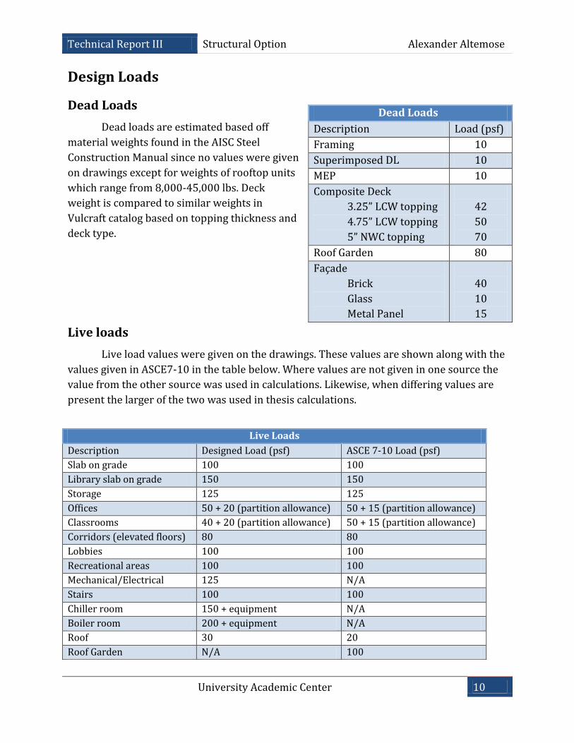
Dead loads are estimated based off
material weights found in the AISC Steel
Construction Manual since no values were given
on drawings except for weights of rooftop units
which range from 8,000-45,000 lbs. Deck
weight is compared to similar weights in
Vulcraft catalog based on topping thickness and
deck type.
Live loads
Live load values were given on the drawings. These values are shown along with the
values given in ASCE7-10 in the table below. Where values are not given in one source the
value from the other source was used in calculations. Likewise, when differing values are
present the larger of the two was used in thesis calculations.
Dead Loads
Description Load (psf)
Framing 10
Superimposed DL 10
MEP 10
Composite Deck
3.25” LCW topping
4.75” LCW topping
5” NWC topping
42
50
70
Roof Garden 80
Façade
Brick
Glass
Metal Panel
40
10
15
Live Loads
Description Designed Load (psf) ASCE 7-10 Load (psf)
Slab on grade 100 100
Library slab on grade 150 150
Storage 125 125
Offices 50 + 20 (partition allowance) 50 + 15 (partition allowance)
Classrooms 40 + 20 (partition allowance) 50 + 15 (partition allowance)
Corridors (elevated floors) 80 80
Lobbies 100 100
Recreational areas 100 100
Mechanical/Electrical 125 N/A
Stairs 100 100
Chiller room 150 + equipment N/A
Boiler room 200 + equipment N/A
Roof 30 20
Roof Garden N/A 100
University Academic Center 11
Technical Report III Structural Option Alexander Altemose
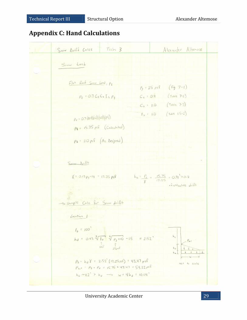
Snow Loads
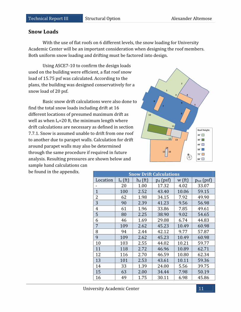
With the use of flat roofs on 6 different levels, the snow loading for University
Academic Center will be an important consideration when designing the roof members.
Both uniform snow loading and drifting must be factored into design.
Using ASCE7-10 to confirm the design loads
used on the building were efficient, a flat roof snow
load of 15.75 psf was calculated. According to the
plans, the building was designed conservatively for a
snow load of 20 psf.
Basic snow drift calculations were also done to
find the total snow loads including drift at 16
different locations of presumed maximum drift as
well as when Iu=20 ft, the minimum length where
drift calculations are necessary as defined in section
7.7.1. Snow is assumed unable to drift from one roof
to another due to parapet walls. Calculation for drift
around parapet walls may also be determined
through the same procedure if required in future
analysis. Resulting pressures are shown below and
sample hand calculations can
be found in the appendix.
Snow Drift Calculations Location Iu (ft) hd (ft) pd (psf) w (ft) ptot (psf) - 20 1.00 17.32 4.02 33.07 1 100 2.52 43.40 10.06 59.15 2 62 1.98 34.15 7.92 49.90 3 90 2.39 41.23 9.56 56.98 4 61 1.96 33.86 7.85 49.61 5 80 2.25 38.90 9.02 54.65 6 46 1.69 29.08 6.74 44.83 7 109 2.62 45.23 10.49 60.98 8 94 2.44 42.12 9.77 57.87 9 109 2.62 45.23 10.49 60.98 10 103 2.55 44.02 10.21 59.77 11 118 2.72 46.96 10.89 62.71 12 116 2.70 46.59 10.80 62.34 13 101 2.53 43.61 10.11 59.36 14 33 1.39 24.00 5.56 39.75 15 63 2.00 34.44 7.98 50.19 16 49 1.75 30.11 6.98 45.86
University Academic Center 12
Technical Report III Structural Option Alexander Altemose
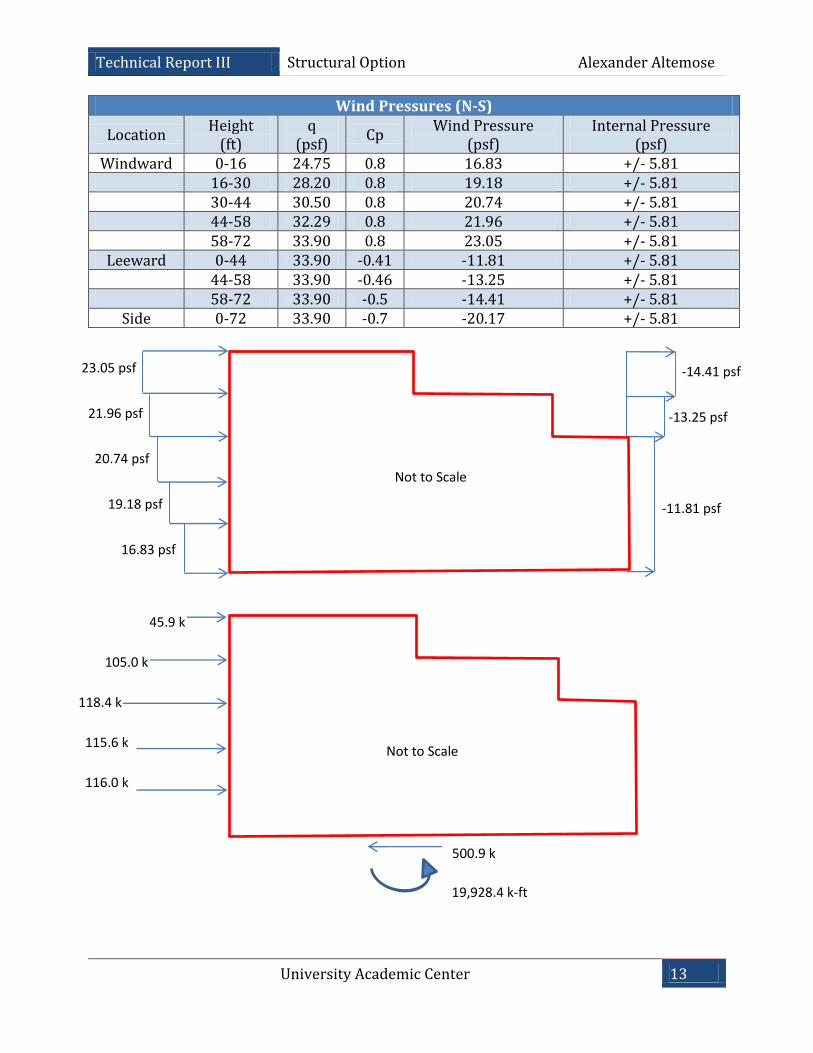
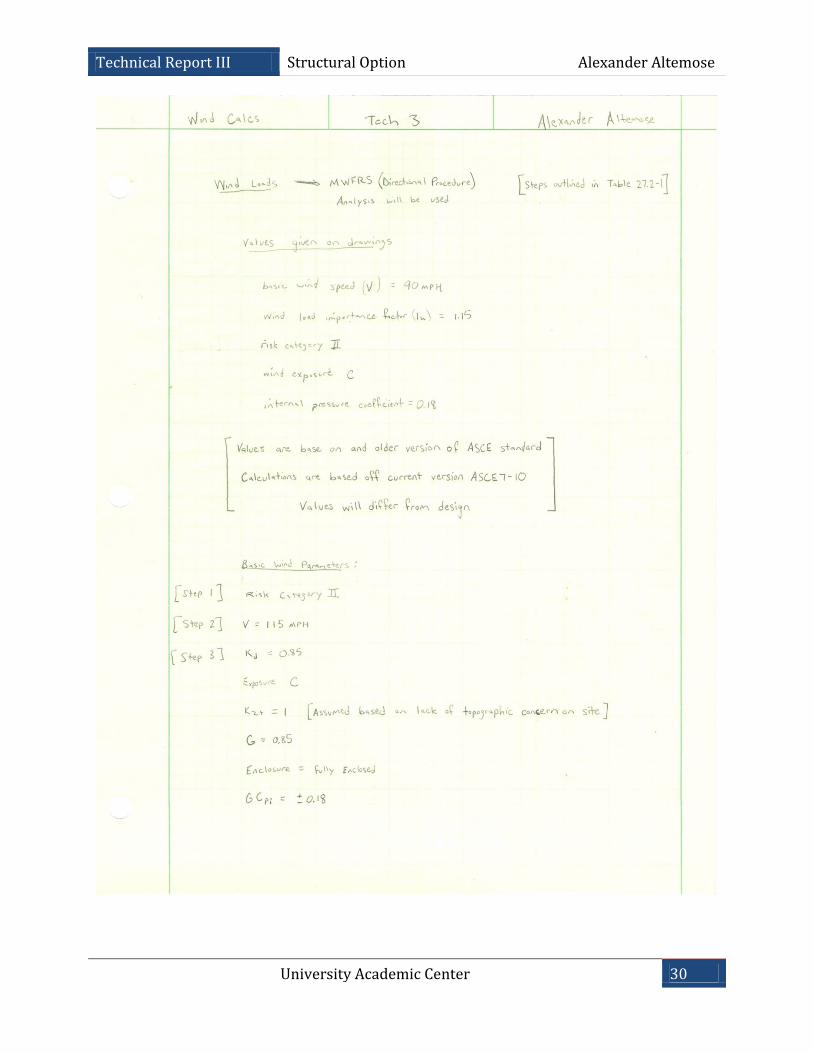
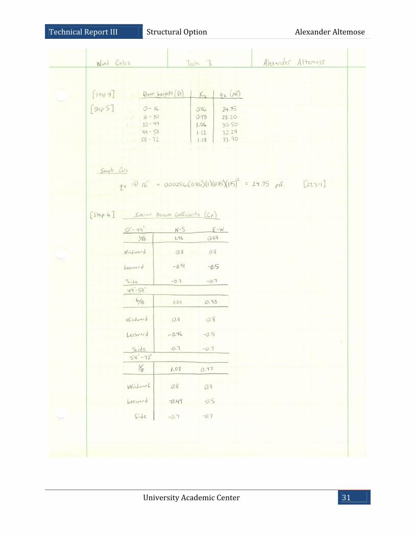
Wind Loads
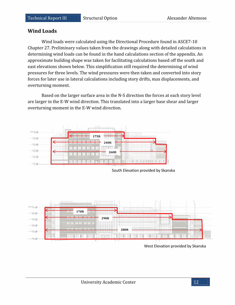
Wind loads were calculated using the Directional Procedure found in ASCE7-10
Chapter 27. Preliminary values taken from the drawings along with detailed calculations in
determining wind loads can be found in the hand calculations section of the appendix. An
approximate building shape was taken for facilitating calculations based off the south and
east elevations shown below. This simplification still required the determining of wind
pressures for three levels. The wind pressures were then taken and converted into story
forces for later use in lateral calculations including story drifts, max displacements, and
overturning moment.
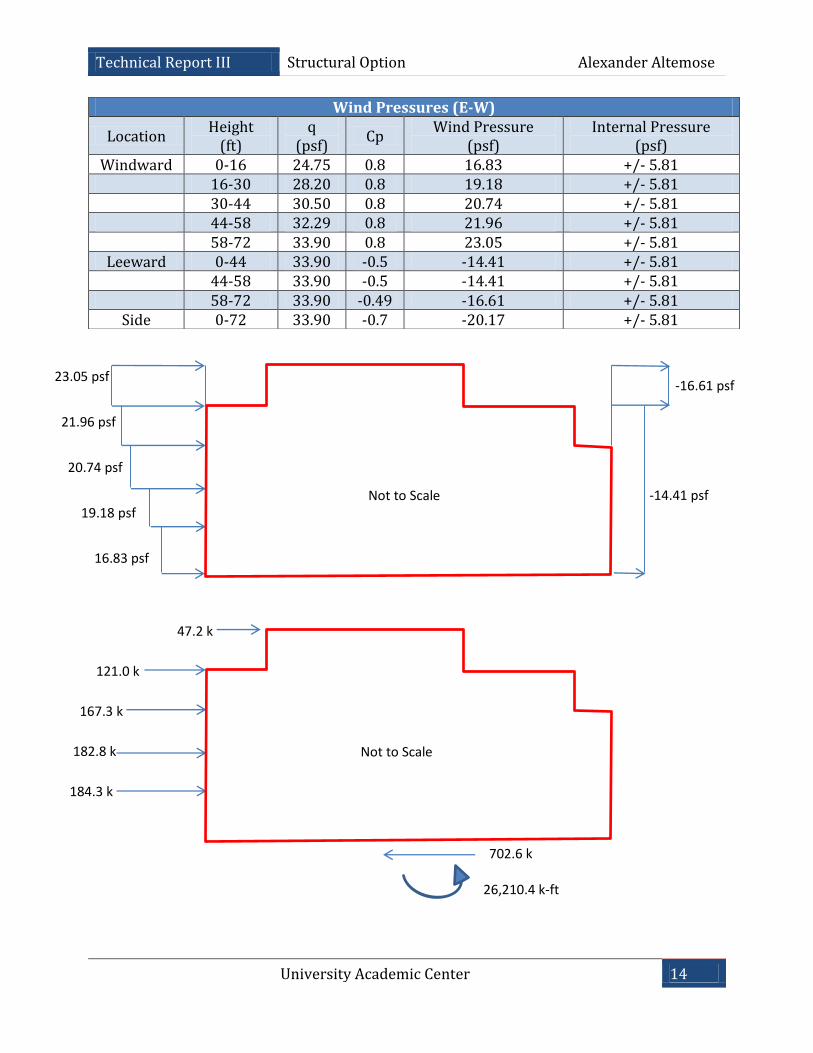
Based on the larger surface area in the N-S direction the forces at each story level
are larger in the E-W wind direction. This translated into a larger base shear and larger
overturning moment in the E-W wind direction.
175ft
240ft
290ft
260ft
170ft
380ft
South Elevation provided by Skanska
West Elevation provided by Skanska
University Academic Center 13
Technical Report III Structural Option Alexander Altemose
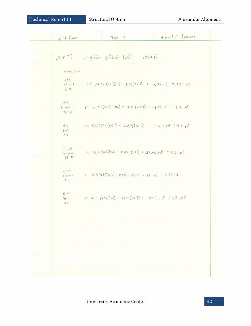
Wind Pressures (N-S)
Location Height
(ft) q
(psf) Cp
Wind Pressure (psf)
Internal Pressure (psf)
Windward 0-16 24.75 0.8 16.83 +/- 5.81 16-30 28.20 0.8 19.18 +/- 5.81 30-44 30.50 0.8 20.74 +/- 5.81 44-58 32.29 0.8 21.96 +/- 5.81
58-72 33.90 0.8 23.05 +/- 5.81
Leeward 0-44 33.90 -0.41 -11.81 +/- 5.81
44-58 33.90 -0.46 -13.25 +/- 5.81
58-72 33.90 -0.5 -14.41 +/- 5.81
Side 0-72 33.90 -0.7 -20.17 +/- 5.81
Not to Scale
23.05 psf
21.96 psf
20.74 psf
19.18 psf
16.83 psf
-14.41 psf
-13.25 psf
-11.81 psf
Not to Scale
45.9 k
105.0 k
118.4 k
115.6 k
116.0 k
500.9 k
19,928.4 k-ft
University Academic Center 14
Technical Report III Structural Option Alexander Altemose
Wind Pressures (E-W)
Location Height
(ft) q
(psf) Cp
Wind Pressure (psf)
Internal Pressure (psf)
Windward 0-16 24.75 0.8 16.83 +/- 5.81 16-30 28.20 0.8 19.18 +/- 5.81 30-44 30.50 0.8 20.74 +/- 5.81 44-58 32.29 0.8 21.96 +/- 5.81
58-72 33.90 0.8 23.05 +/- 5.81
Leeward 0-44 33.90 -0.5 -14.41 +/- 5.81
44-58 33.90 -0.5 -14.41 +/- 5.81
58-72 33.90 -0.49 -16.61 +/- 5.81
Side 0-72 33.90 -0.7 -20.17 +/- 5.81
47.2 k
121.0 k
167.3 k
182.8 k
184.3 k
Not to Scale
Not to Scale
23.05 psf
21.96 psf
20.74 psf
19.18 psf
16.83 psf
-14.41 psf
702.6 k
26,210.4 k-ft
-16.61 psf
University Academic Center 15
Technical Report III Structural Option Alexander Altemose
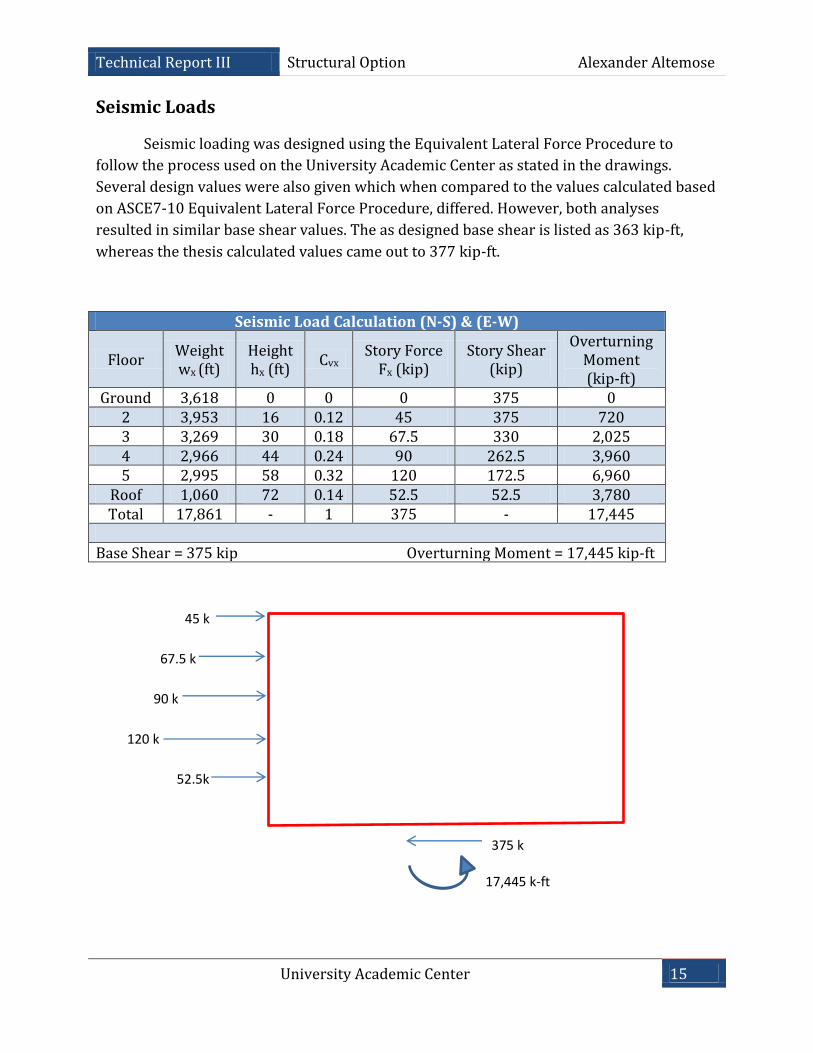
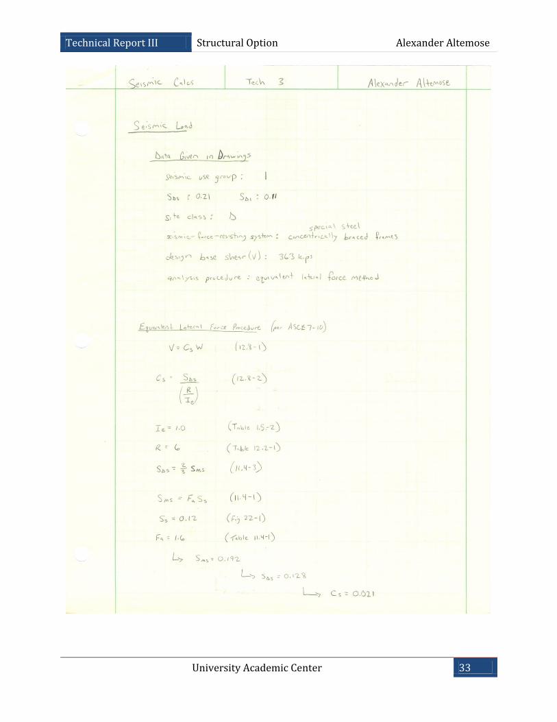
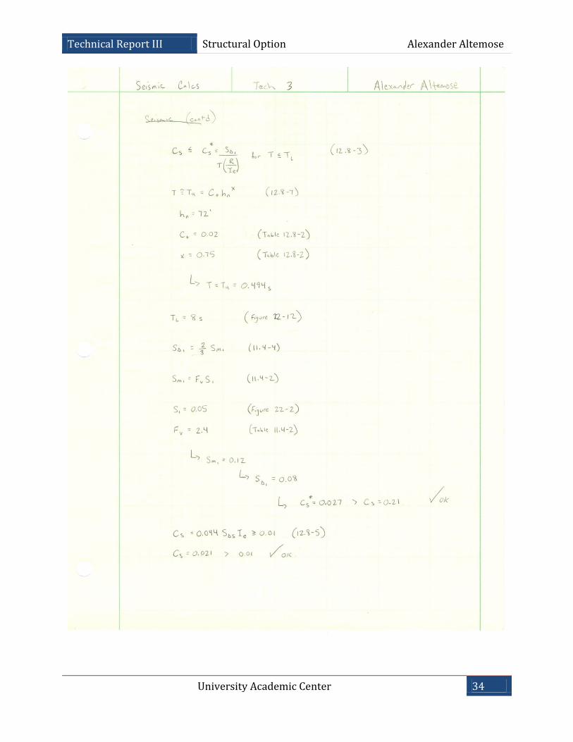
Seismic Loads
Seismic loading was designed using the Equivalent Lateral Force Procedure to
follow the process used on the University Academic Center as stated in the drawings.
Several design values were also given which when compared to the values calculated based
on ASCE7-10 Equivalent Lateral Force Procedure, differed. However, both analyses
resulted in similar base shear values. The as designed base shear is listed as 363 kip-ft,
whereas the thesis calculated values came out to 377 kip-ft.
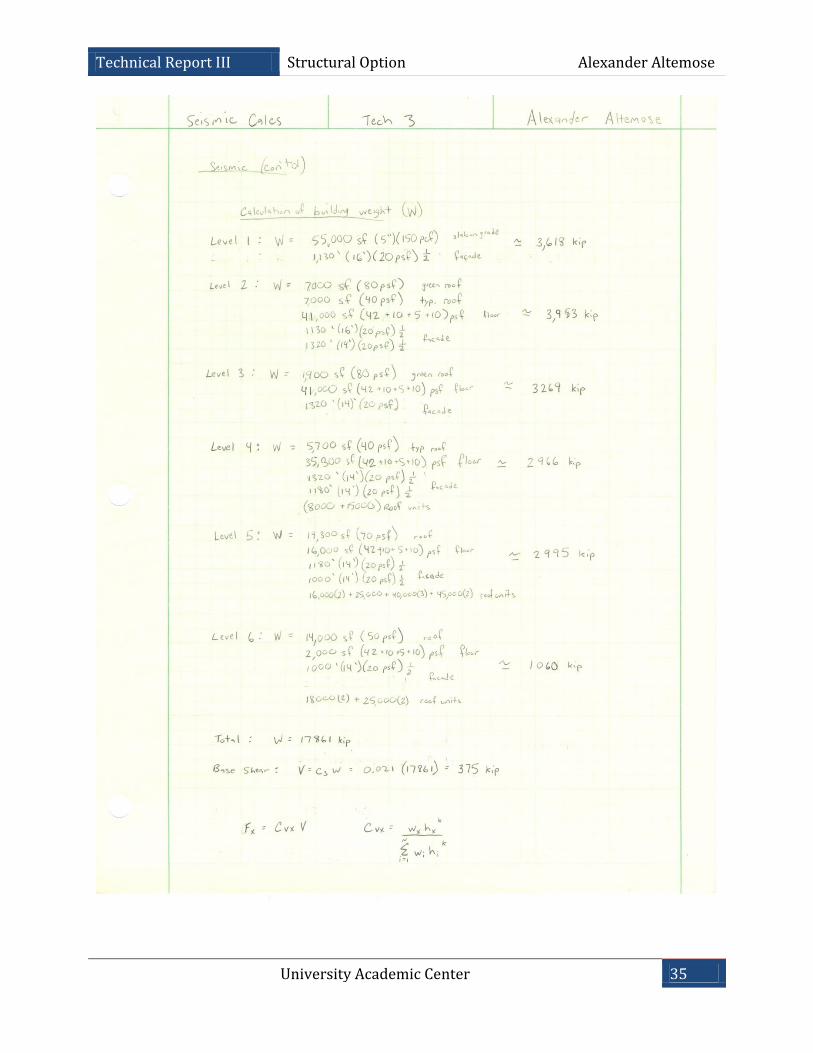
Seismic Load Calculation (N-S) & (E-W)
Floor Weight wx (ft)
Height hx (ft)
Cvx Story Force
Fx (kip) Story Shear
(kip)
Overturning Moment (kip-ft)
Ground 3,618 0 0 0 375 0 2 3,953 16 0.12 45 375 720 3 3,269 30 0.18 67.5 330 2,025 4 2,966 44 0.24 90 262.5 3,960 5 2,995 58 0.32 120 172.5 6,960
Roof 1,060 72 0.14 52.5 52.5 3,780 Total 17,861 - 1 375 - 17,445
Base Shear = 375 kip Overturning Moment = 17,445 kip-ft
45 k
67.5 k
90 k
120 k
52.5k
375 k
17,445 k-ft
University Academic Center 16
Technical Report III Structural Option Alexander Altemose
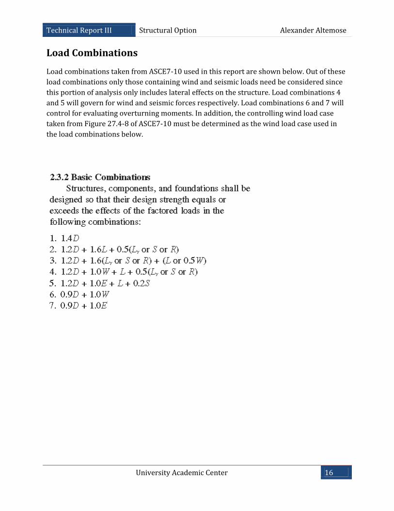
Load Combinations
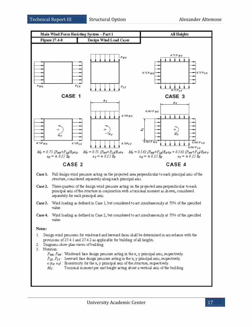
Load combinations taken from ASCE7-10 used in this report are shown below. Out of these
load combinations only those containing wind and seismic loads need be considered since
this portion of analysis only includes lateral effects on the structure. Load combinations 4
and 5 will govern for wind and seismic forces respectively. Load combinations 6 and 7 will
control for evaluating overturning moments. In addition, the controlling wind load case
taken from Figure 27.4-8 of ASCE7-10 must be determined as the wind load case used in
the load combinations below.
University Academic Center 17
Technical Report III Structural Option Alexander Altemose
University Academic Center 18
Technical Report III Structural Option Alexander Altemose
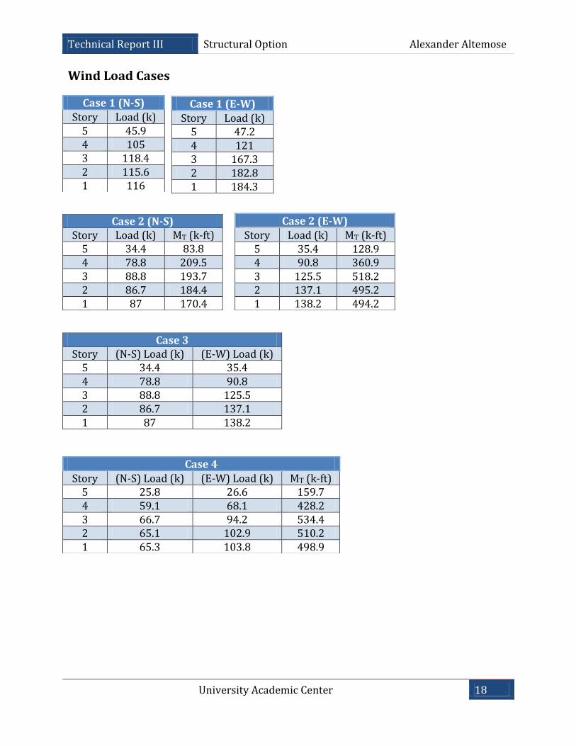
Wind Load Cases
Case 1 (N-S) Story Load (k)
5 45.9 4 105 3 118.4 2 115.6 1 116
Case 1 (E-W)
Story Load (k) 5 47.2 4 121 3 167.3 2 182.8 1 184.3
Case 2 (N-S) Story Load (k) MT (k-ft)
5 34.4 83.8 4 78.8 209.5 3 88.8 193.7 2 86.7 184.4 1 87 170.4
Case 2 (E-W) Story Load (k) MT (k-ft)
5 35.4 128.9 4 90.8 360.9 3 125.5 518.2 2 137.1 495.2 1 138.2 494.2
Case 3 Story (N-S) Load (k) (E-W) Load (k)
5 34.4 35.4 4 78.8 90.8 3 88.8 125.5 2 86.7 137.1 1 87 138.2
Case 4
Story (N-S) Load (k) (E-W) Load (k) MT (k-ft) 5 25.8 26.6 159.7 4 59.1 68.1 428.2 3 66.7 94.2 534.4 2 65.1 102.9 510.2 1 65.3 103.8 498.9
University Academic Center 19
Technical Report III Structural Option Alexander Altemose
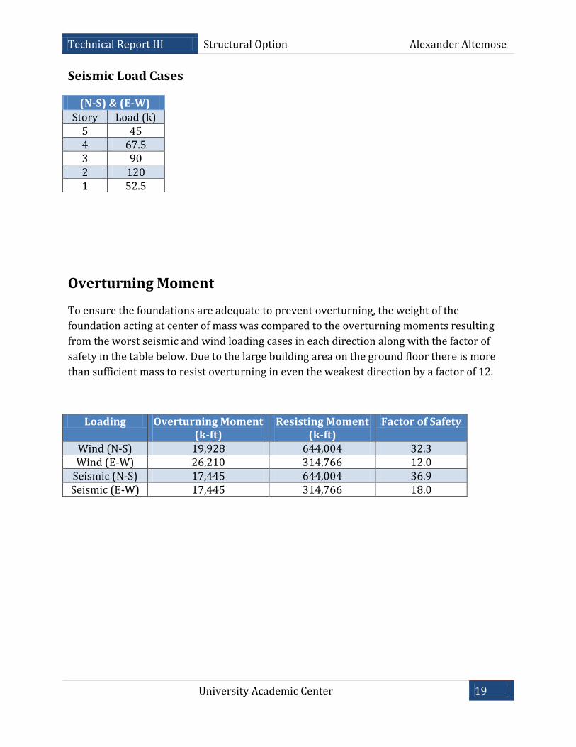
Seismic Load Cases
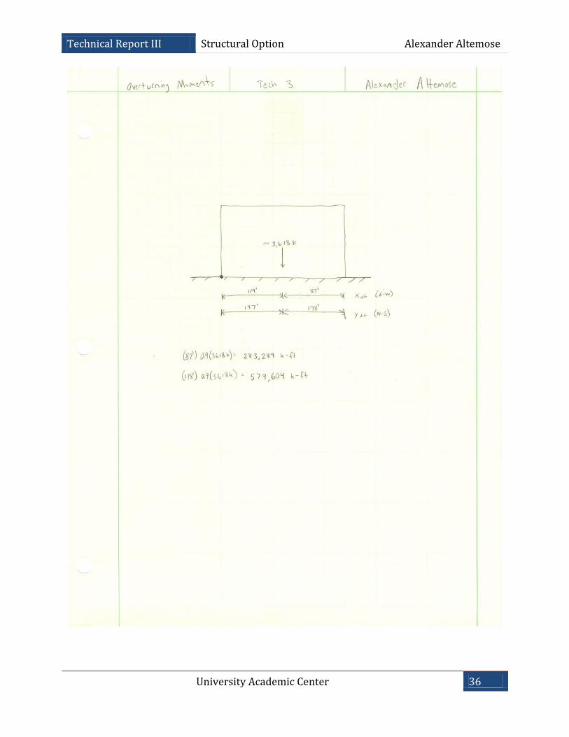
Overturning Moment
To ensure the foundations are adequate to prevent overturning, the weight of the
foundation acting at center of mass was compared to the overturning moments resulting
from the worst seismic and wind loading cases in each direction along with the factor of
safety in the table below. Due to the large building area on the ground floor there is more
than sufficient mass to resist overturning in even the weakest direction by a factor of 12.
Loading Overturning Moment (k-ft)
Resisting Moment (k-ft)
Factor of Safety
Wind (N-S) 19,928 644,004 32.3 Wind (E-W) 26,210 314,766 12.0
Seismic (N-S) 17,445 644,004 36.9 Seismic (E-W) 17,445 314,766 18.0
(N-S) & (E-W) Story Load (k)
5 45 4 67.5 3 90 2 120 1 52.5
University Academic Center 20
Technical Report III Structural Option Alexander Altemose
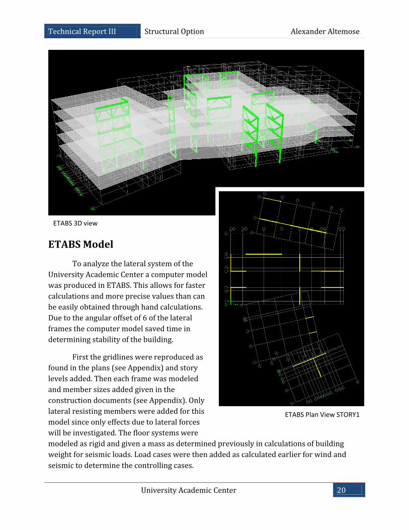
ETABS Model
To analyze the lateral system of the
University Academic Center a computer model
was produced in ETABS. This allows for faster
calculations and more precise values than can
be easily obtained through hand calculations.
Due to the angular offset of 6 of the lateral
frames the computer model saved time in
determining stability of the building.
First the gridlines were reproduced as
found in the plans (see Appendix) and story
levels added. Then each frame was modeled
and member sizes added given in the
construction documents (see Appendix). Only
lateral resisting members were added for this
model since only effects due to lateral forces
will be investigated. The floor systems were
modeled as rigid and given a mass as determined previously in calculations of building
weight for seismic loads. Load cases were then added as calculated earlier for wind and
seismic to determine the controlling cases.
ETABS Plan View STORY1
ETABS 3D view
University Academic Center 21
Technical Report III Structural Option Alexander Altemose
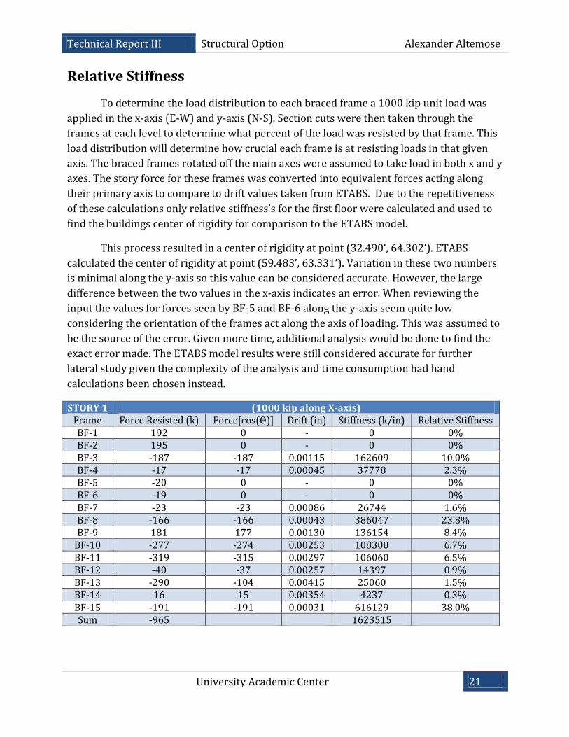
Relative Stiffness
To determine the load distribution to each braced frame a 1000 kip unit load was
applied in the x-axis (E-W) and y-axis (N-S). Section cuts were then taken through the
frames at each level to determine what percent of the load was resisted by that frame. This
load distribution will determine how crucial each frame is at resisting loads in that given
axis. The braced frames rotated off the main axes were assumed to take load in both x and y
axes. The story force for these frames was converted into equivalent forces acting along
their primary axis to compare to drift values taken from ETABS. Due to the repetitiveness
of these calculations only relative stiffness’s for the first floor were calculated and used to
find the buildings center of rigidity for comparison to the ETABS model.
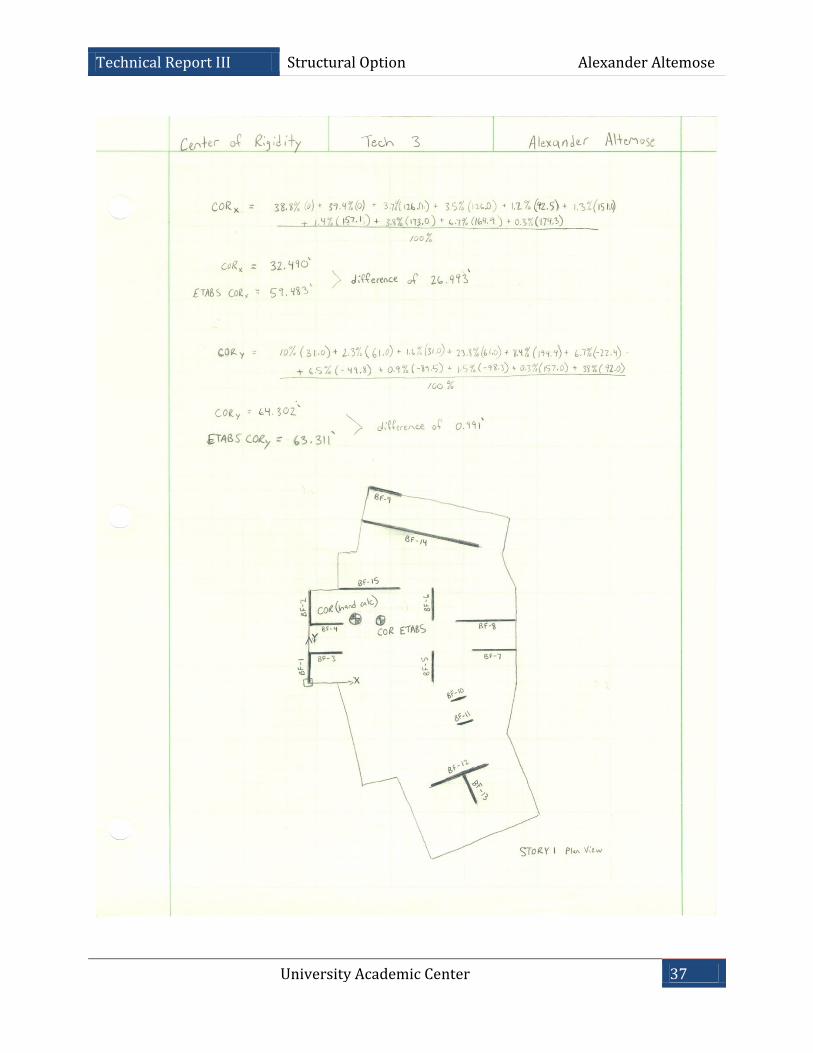
This process resulted in a center of rigidity at point (32.490’, 64.302’). ETABS
calculated the center of rigidity at point (59.483’, 63.331’). Variation in these two numbers
is minimal along the y-axis so this value can be considered accurate. However, the large
difference between the two values in the x-axis indicates an error. When reviewing the
input the values for forces seen by BF-5 and BF-6 along the y-axis seem quite low
considering the orientation of the frames act along the axis of loading. This was assumed to
be the source of the error. Given more time, additional analysis would be done to find the
exact error made. The ETABS model results were still considered accurate for further
lateral study given the complexity of the analysis and time consumption had hand
calculations been chosen instead.
STORY 1 (1000 kip along X-axis) Frame Force Resisted (k) Force[cos(Ө)] Drift (in) Stiffness (k/in) Relative Stiffness BF-1 192 0 - 0 0% BF-2 195 0 - 0 0% BF-3 -187 -187 0.00115 162609 10.0% BF-4 -17 -17 0.00045 37778 2.3% BF-5 -20 0 - 0 0% BF-6 -19 0 - 0 0% BF-7 -23 -23 0.00086 26744 1.6% BF-8 -166 -166 0.00043 386047 23.8% BF-9 181 177 0.00130 136154 8.4%
BF-10 -277 -274 0.00253 108300 6.7% BF-11 -319 -315 0.00297 106060 6.5% BF-12 -40 -37 0.00257 14397 0.9% BF-13 -290 -104 0.00415 25060 1.5% BF-14 16 15 0.00354 4237 0.3% BF-15 -191 -191 0.00031 616129 38.0% Sum -965 1623515
University Academic Center 22
Technical Report III Structural Option Alexander Altemose
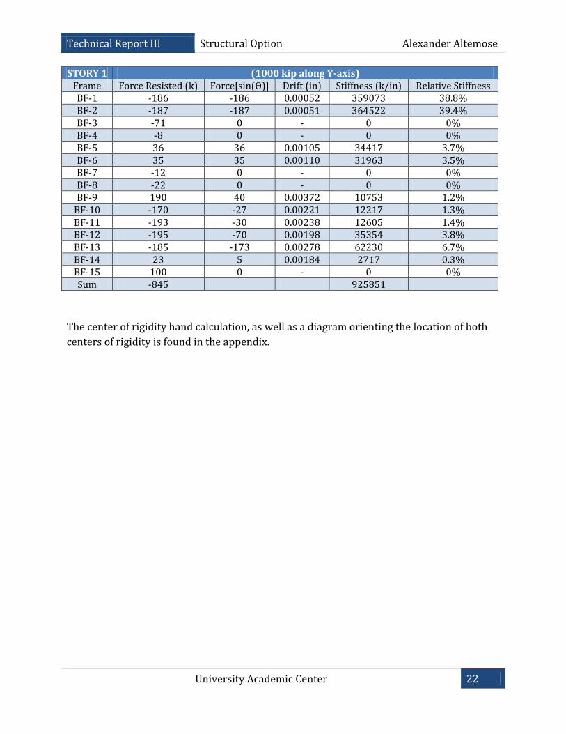
STORY 1 (1000 kip along Y-axis) Frame Force Resisted (k) Force[sin(Ө)] Drift (in) Stiffness (k/in) Relative Stiffness BF-1 -186 -186 0.00052 359073 38.8% BF-2 -187 -187 0.00051 364522 39.4% BF-3 -71 0 - 0 0% BF-4 -8 0 - 0 0% BF-5 36 36 0.00105 34417 3.7% BF-6 35 35 0.00110 31963 3.5% BF-7 -12 0 - 0 0% BF-8 -22 0 - 0 0% BF-9 190 40 0.00372 10753 1.2%
BF-10 -170 -27 0.00221 12217 1.3% BF-11 -193 -30 0.00238 12605 1.4% BF-12 -195 -70 0.00198 35354 3.8% BF-13 -185 -173 0.00278 62230 6.7% BF-14 23 5 0.00184 2717 0.3% BF-15 100 0 - 0 0% Sum -845 925851
The center of rigidity hand calculation, as well as a diagram orienting the location of both
centers of rigidity is found in the appendix.
University Academic Center 23
Technical Report III Structural Option Alexander Altemose
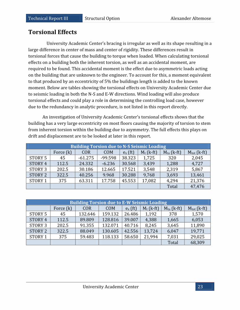
Torsional Effects
University Academic Center’s bracing is irregular as well as its shape resulting in a
large difference in center of mass and center of rigidity. These differences result in
torsional forces that cause the building to torque when loaded. When calculating torsional
effects on a building both the inherent torsion, as well as an accidental moment, are
required to be found. This accidental moment is the effect due to asymmetric loads acting
on the building that are unknown to the engineer. To account for this, a moment equivalent
to that produced by an eccentricity of 5% the buildings length is added to the known
moment. Below are tables showing the torsional effects on University Academic Center due
to seismic loading in both the N-S and E-W directions. Wind loading will also produce
torsional effects and could play a role in determining the controlling load case, however
due to the redundancy in analytic procedure, is not listed in this report directly.
An investigation of University Academic Center’s torsional effects shows that the
building has a very large eccentricity on most floors causing the majority of torsion to stem
from inherent torsion within the building due to asymmetry. The full effects this plays on
drift and displacement are to be looked at later in this report.
Building Torsion due to N-S Seismic Loading Force (k) COR COM ex (ft) Mt (k-ft) Mta (k-ft) Mtot (k-ft)
STORY 5 45 -61.275 -99.598 38.323 1,725 320 2,045 STORY 4 112.5 24.332 -6.236 30.568 3,439 1,288 4,727 STORY 3 202.5 30.186 12.665 17.521 3,548 2,319 5,867 STORY 2 322.5 40.256 9.968 30.288 9,768 3,693 13,461 STORY 1 375 63.311 17.758 45.553 17,082 4,294 21,376
Total 47,476
Building Torsion due to E-W Seismic Loading Force (k) COR COM ex (ft) Mt (k-ft) Mta (k-ft) Mtot (k-ft)
STORY 5 45 132.646 159.132 26.486 1,192 378 1,570 STORY 4 112.5 89.809 128.816 39.007 4,388 1,665 6,053 STORY 3 202.5 91.355 132.071 40.716 8,245 3,645 11,890 STORY 2 322.5 88.049 130.605 42.556 13,724 6,047 19,771 STORY 1 375 59.483 118.133 58.650 21,994 7,031 29,025
Total 68,309
University Academic Center 24
Technical Report III Structural Option Alexander Altemose
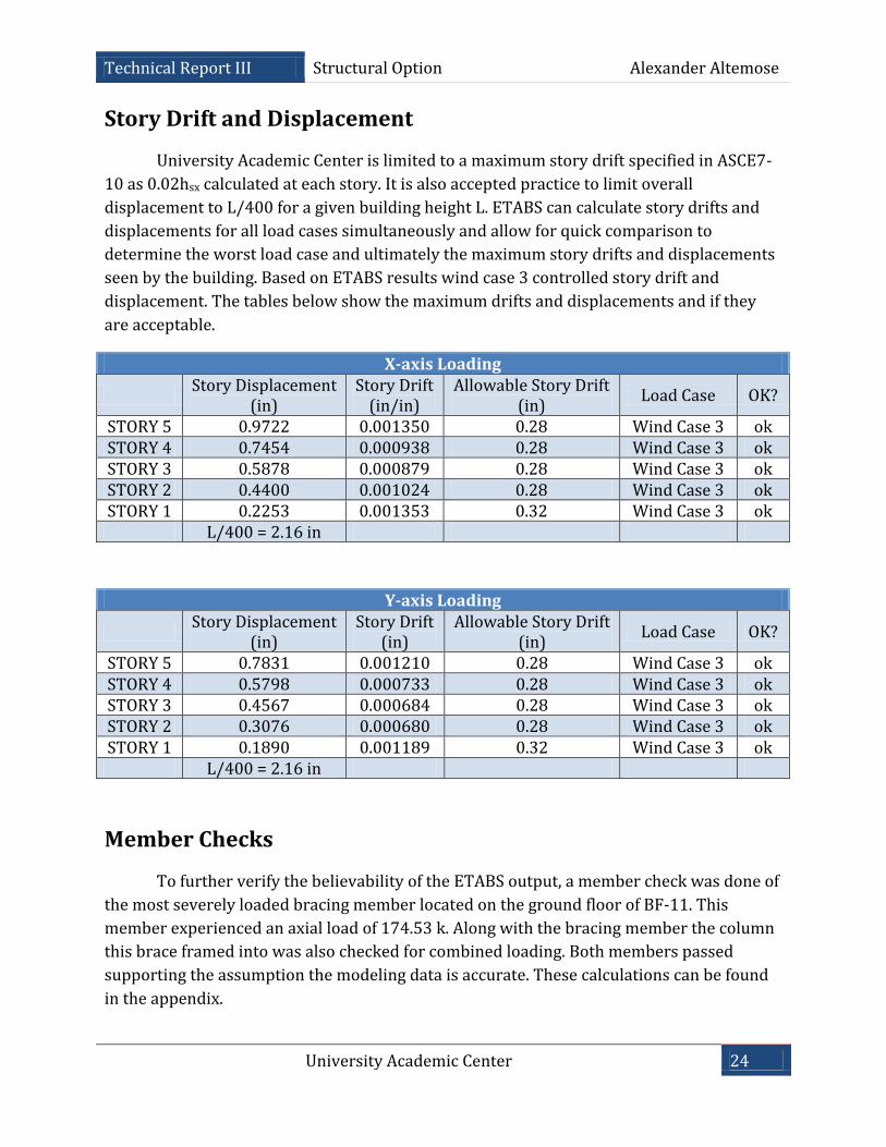
Story Drift and Displacement
University Academic Center is limited to a maximum story drift specified in ASCE7-
10 as 0.02hsx calculated at each story. It is also accepted practice to limit overall
displacement to L/400 for a given building height L. ETABS can calculate story drifts and
displacements for all load cases simultaneously and allow for quick comparison to
determine the worst load case and ultimately the maximum story drifts and displacements
seen by the building. Based on ETABS results wind case 3 controlled story drift and
displacement. The tables below show the maximum drifts and displacements and if they
are acceptable.
X-axis Loading
Story Displacement
(in) Story Drift
(in/in) Allowable Story Drift
(in) Load Case OK?
STORY 5 0.9722 0.001350 0.28 Wind Case 3 ok STORY 4 0.7454 0.000938 0.28 Wind Case 3 ok STORY 3 0.5878 0.000879 0.28 Wind Case 3 ok STORY 2 0.4400 0.001024 0.28 Wind Case 3 ok STORY 1 0.2253 0.001353 0.32 Wind Case 3 ok
L/400 = 2.16 in
Y-axis Loading
Story Displacement
(in) Story Drift
(in) Allowable Story Drift
(in) Load Case OK?
STORY 5 0.7831 0.001210 0.28 Wind Case 3 ok STORY 4 0.5798 0.000733 0.28 Wind Case 3 ok STORY 3 0.4567 0.000684 0.28 Wind Case 3 ok STORY 2 0.3076 0.000680 0.28 Wind Case 3 ok STORY 1 0.1890 0.001189 0.32 Wind Case 3 ok
L/400 = 2.16 in
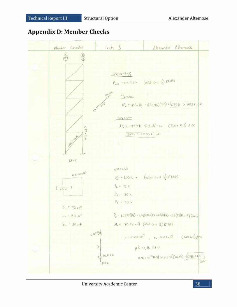
Member Checks
To further verify the believability of the ETABS output, a member check was done of
the most severely loaded bracing member located on the ground floor of BF-11. This
member experienced an axial load of 174.53 k. Along with the bracing member the column
this brace framed into was also checked for combined loading. Both members passed
supporting the assumption the modeling data is accurate. These calculations can be found
in the appendix.
University Academic Center 25
Technical Report III Structural Option Alexander Altemose
Conclusion
The lateral resisting system of University Academic Center proved to be efficient
under the worst load case, wind load case 3. This design provided enough rigidity to meet
displacement requirements while minimizing the reduction of useable space taken up by
framing hidden in walls.
Overturning was concluded not to be of great concern in University Academic
Center due to its large building footprint. The stacking effect of minimizing floor area as the
height increases limits the severity of overturning moments. This design feature is both
visually appealing and functional in reducing stresses on foundation due to uplift.
Torsional effects on the building were large due to the high eccentricities between
center of mass and rigidity. Despite this torsion, no unreasonable displacements in the
building were observed through the use of ETABS computer modeling software. The large
eccentricities are undesirable and could be a possible point of interest in future study as to
whether a redesign could reduce this torsion without drastically changing the building
layout.
University Academic Center 26
Technical Report III Structural Option Alexander Altemose
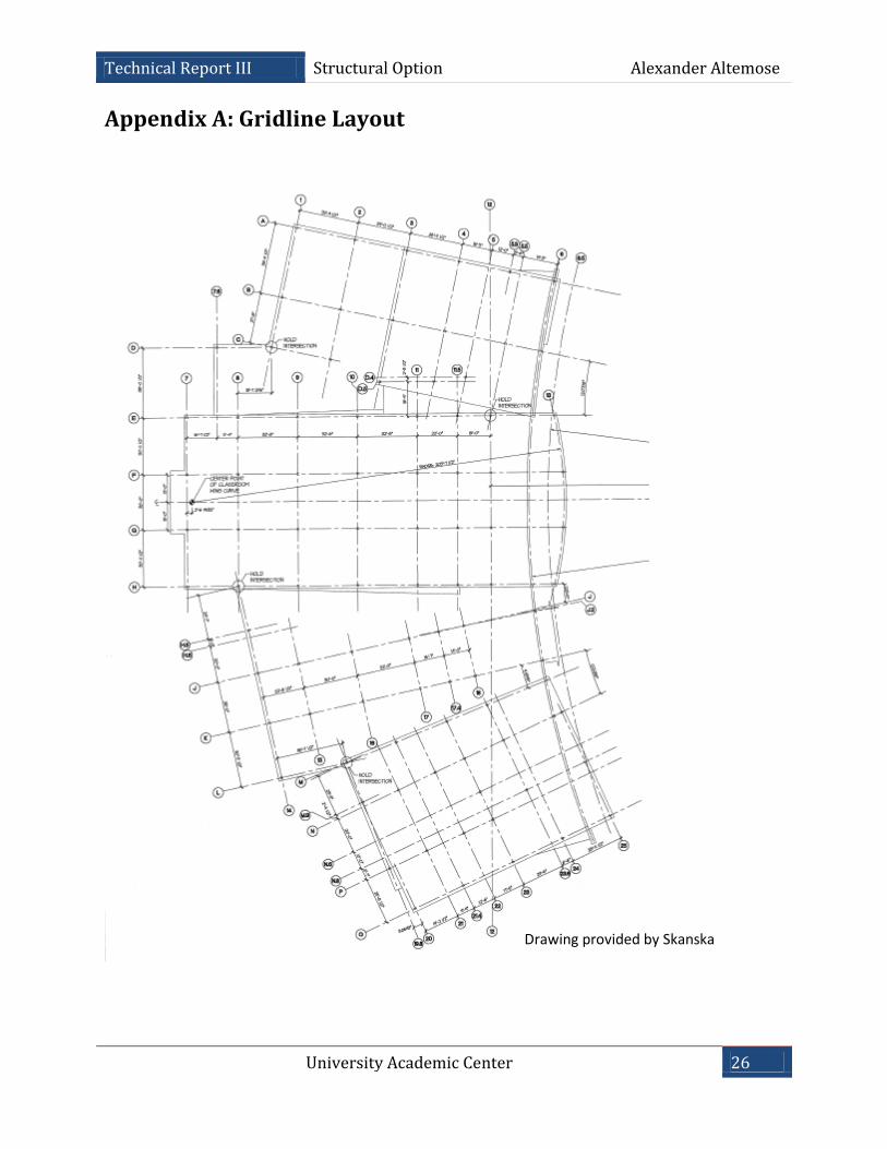
Drawing provided by Skanska
Appendix A: Gridline Layout
University Academic Center 27
Technical Report III Structural Option Alexander Altemose
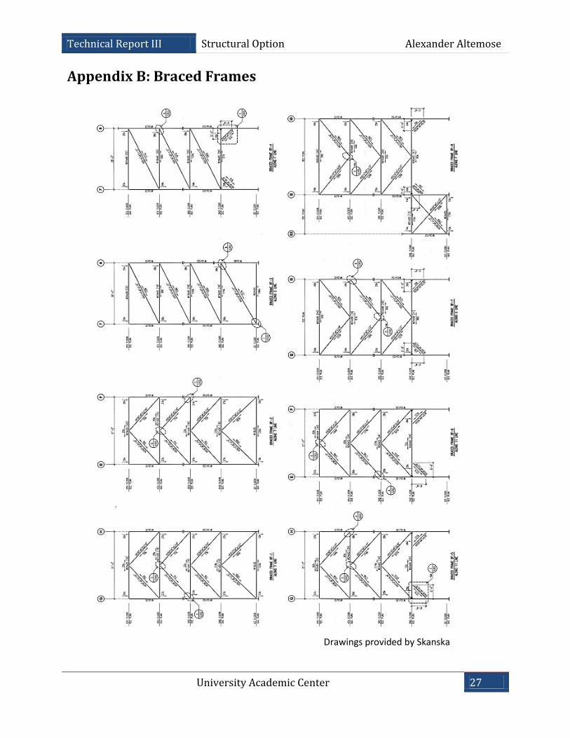
Drawings provided by Skanska
Appendix B: Braced Frames
University Academic Center 28
Technical Report III Structural Option Alexander Altemose
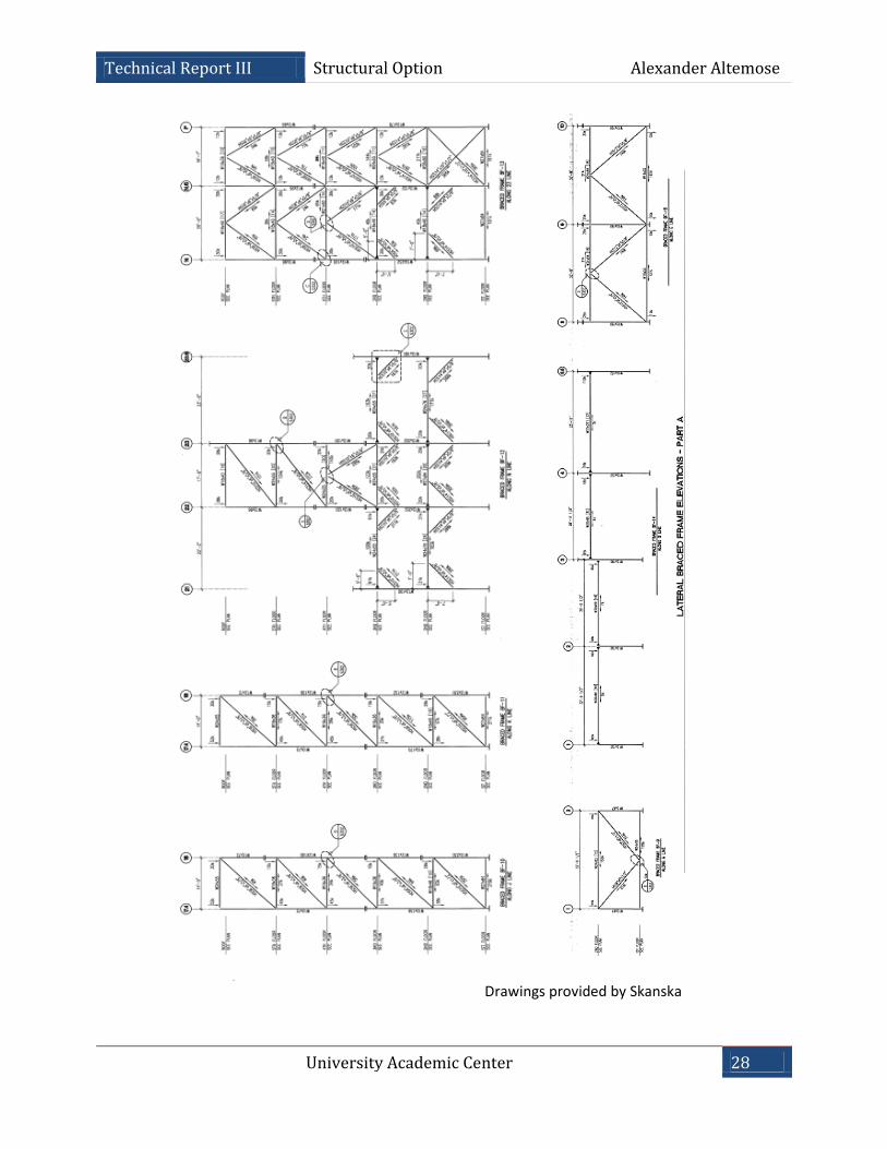
Drawings provided by Skanska
University Academic Center 29
Technical Report III Structural Option Alexander Altemose
Appendix C: Hand Calculations
University Academic Center 30
Technical Report III Structural Option Alexander Altemose
University Academic Center 31
Technical Report III Structural Option Alexander Altemose
University Academic Center 32
Technical Report III Structural Option Alexander Altemose
University Academic Center 33
Technical Report III Structural Option Alexander Altemose
University Academic Center 34
Technical Report III Structural Option Alexander Altemose
University Academic Center 35
Technical Report III Structural Option Alexander Altemose
University Academic Center 36
Technical Report III Structural Option Alexander Altemose
University Academic Center 37
Technical Report III Structural Option Alexander Altemose
University Academic Center 38
Technical Report III Structural Option Alexander Altemose
Appendix D: Member Checks