Embed Size (px)
Citation preview
Gesytec GmbH
Pascalstr. 6
52076 Aachen, Germany
Tel. + (49) 24 08 / 9 44-0
Fax + (49) 24 08 / 94 4-100
email: [email protected]
www.gesytec.com
Doc. ID: LPM3/UserDoc/LPM3_Manual-E-v2.1.docx,
Version v2.1, 01/25/2013
USB Socket Interface User Manual
Easylo USB Socket Interface User Manual
2/27
LP
M3/U
serD
oc/
LP
M_M
anual
-E.d
oc,
v2.1
, 01/2
5/2
013
This manual …
… provides you with all the information which you will require to use the Easy-
lon® USB Socket Interface.
However, this manual will neither explain aspects of Echelon's® LONWORKS®
technology, nor Echelon's Microprocessor Interface Program (MIP) used on this
network interface card. The drivers of the USB Socket Interface have been de-
veloped in compliance with the driver specifications of the Echelon Corporation
Details of these are as well not described in this documentation. For further in-
formation on the LONWORKS technology please refer to the extensive documen-
tation provided by Echelon.
After a general presentation of the Easylon USB Socket Interface in Chapter 1,
Chapter 2 describes the necessary steps to install the module.
Chapter 3 gives the technical specifications of the device and Chapter 4 provides
some programming instruction for operation under Windows CE. Tips and tricks
concerning the operation can be found in Chapter 5.
This documentation is subject to changes without notice. Gesytec assumes no responsibility or
liability for any errors or inaccuracies that may appear in this document.
Gesytec shall have no liability or responsibility to the original purchaser or any other person or
entity with respect to any claim, loss, liability, or damage caused or alleged to be caused directly
or indirectly by any Gesytec product or the accompanying documentation.
Easylon is registered trademark of Gesytec GmbH.
Echelon, LON, LonMaker, LONWORKS, and NEURON are registered trademarks of Echelon Corporation.
Windows is a registered trademark of Microsoft. Other names may be trademarks of their respective com-
panies.
The Easylon USB Socket Interface incorporates the MIP program by Echelon Corporation. The aforesaid
company holds all rights relating to this software.
Easylo USB Socket Interface User Manual Contents
3/27
LP
M3/U
serD
oc/
LP
M_M
anual
-E.d
oc,
v2.1
, 01/2
5/2
013
Contents 1 Product Information ..........................................................................................................4
1.1 Variants ..................................................................................................................4
1.2 Scope of Delivery ..................................................................................................4
1.3 Overview ................................................................................................................5
2 Installation ..........................................................................................................................7
2.1 Hardware Installation .............................................................................................7
2.1.1 Pin assignment .......................................................................................................7
2.2 Driver Installation ..................................................................................................8
2.2.1 Driver for Windows Operating System (WDM Drivers) ......................................8
2.2.1.1 Installation..............................................................................................................8
2.2.1.2 Manual Installation and Update ...........................................................................12
2.2.1.3 Settings .................................................................................................................12
2.2.2 Windows and 16 Bit Applications .......................................................................14
2.2.3 EasyCheck – Quick Interface Diagnosis..............................................................15
2.2.4 Windows CE Driver .............................................................................................15
2.2.4.1 Copy .dll to Windows Directory ..........................................................................15
2.2.4.2 Integration into Windows CE Image ...................................................................15
3 Technical Specifications ..................................................................................................18
4 Programming Instructions ..............................................................................................20
4.1 Windows CE Application Interface .....................................................................20
4.1.1 CreateFile .............................................................................................................20
4.1.2 CloseHandle .........................................................................................................20
4.1.3 ReadFile ...............................................................................................................20
4.1.4 WriteFile ..............................................................................................................21
4.1.5 GetVersion ...........................................................................................................21
4.1.6 ReadFile with Timeout ........................................................................................22
4.1.7 Set Timeout for ReadFile .....................................................................................22
4.1.8 Registry entries for Easylon USB Interface .........................................................23
5 Tips and Tricks ................................................................................................................24
5.1 Hot Plugging ........................................................................................................24
5.2 Using an USB Hub...............................................................................................24
5.3 Standby Mode of PC ............................................................................................24
5.4 Hibernation Mode of PC ......................................................................................24
5.5 Registry Key ........................................................................................................25
6 List of Figures ...................................................................................................................26
7 List of Tables ....................................................................................................................26
8 Index ..................................................................................................................................27
Easylo USB Socket Interface User Manual Product Information
4/27
LP
M3/U
serD
oc/
LP
M_M
anual
-E.d
oc,
v2.1
, 01/2
5/2
013
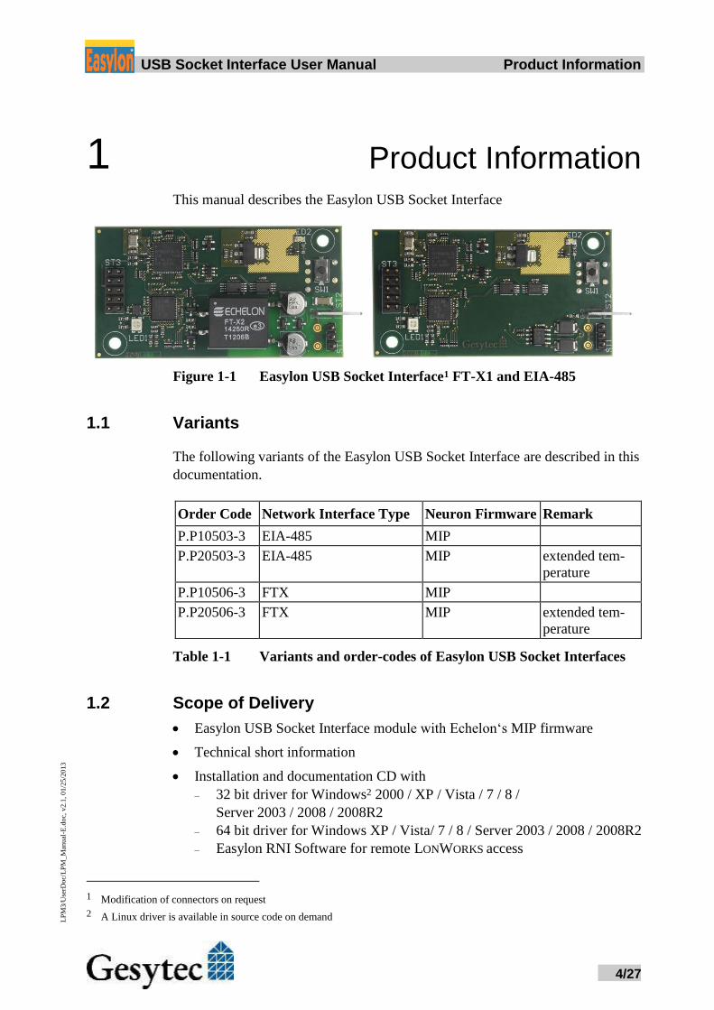
1 Product Information This manual describes the Easylon USB Socket Interface
Figure 1-1 Easylon USB Socket Interface1 FT-X1 and EIA-485
1.1 Variants
The following variants of the Easylon USB Socket Interface are described in this
documentation.
Order Code Network Interface Type Neuron Firmware Remark
P.P10503-3 EIA-485 MIP
P.P20503-3 EIA-485 MIP extended tem-
perature
P.P10506-3 FTX MIP
P.P20506-3 FTX MIP extended tem-
perature
Table 1-1 Variants and order-codes of Easylon USB Socket Interfaces
1.2 Scope of Delivery
Easylon USB Socket Interface module with Echelon‘s MIP firmware
Technical short information
Installation and documentation CD with
– 32 bit driver for Windows2 2000 / XP / Vista / 7 / 8 /
Server 2003 / 2008 / 2008R2
– 64 bit driver for Windows XP / Vista/ 7 / 8 / Server 2003 / 2008 / 2008R2
– Easylon RNI Software for remote LONWORKS access
1 Modification of connectors on request
2 A Linux driver is available in source code on demand
Easylo USB Socket Interface User Manual Product Information
5/27
LP
M3/U
serD
oc/
LP
M_M
anual
-E.d
oc,
v2.1
, 01/2
5/2
013
– EasyCheck diagnosis utility for Easylon interfaces
– Documentation in Adobe Acrobat .PDF format
– Sample design for a carrier board (Gerber and Step files)
1.3 Overview
The Easylon USB Socket Interface realizes a LON-USB connection as a plug-in
module, to be integrated into OEM devices. USB connection to the CPU board is
made by a 10pin connector designed according the ASUS standard. Power sup-
ply uses this connector as well.
As an OEM module a certain flexibility with respect to customer specific re-
quirements is observed, e.g. with respect to the connector types or positions. The
respective module may therefore be different from the description in this docu-
mentation.
An Evaluation Kit available to the Easylon USB Socket Interface allows easy ac-
cess to connections and signals of the board.
The module is available in different transceiver variants all with MIP firmware.
Additionally to the FTX transceiver there is EIA-485. Furthermore there are var-
iants for extended temperature range. Service button and ~LED are implemented.
Note Due to the usage of the Neuron 5000 with MIP firmware this module is not suit-
ed for LNS based applications.
The driver for the Easylon USB Socket Interface is compliant with Echelon’s
driver interface. Applications using the driver interface directly can use the inter-
face without problems. The Easylon USB Socket Interface is compatible with the
Easylon OPC Server and Gesytec’s WLDV32.DLL.
The Easylon USB Socket Interface is a so called high speed USB device accord-
ing to USB standard 2.0, however compatible with USB 1.1. The communication
between the Neuron chip and USB is handled by a micro controller. The firm-
ware for this micro controller is downloaded automatically, when the PC is start-
ed.
2 3
4
1
1 2
5
6
1
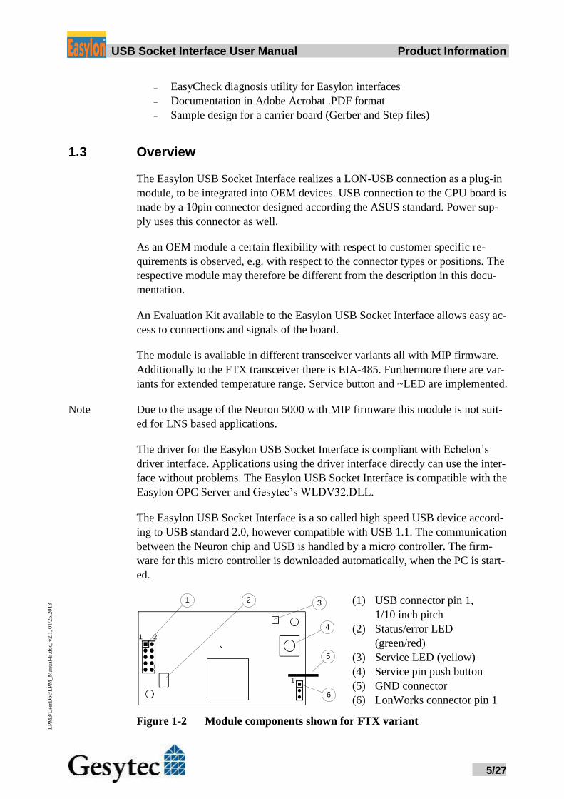
(1) USB connector pin 1,
1/10 inch pitch
(2) Status/error LED
(green/red)
(3) Service LED (yellow)
(4) Service pin push button
(5) GND connector
(6) LonWorks connector pin 1
Figure 1-2 Module components shown for FTX variant
Easylo USB Socket Interface User Manual Product Information
6/27
LP
M3/U
serD
oc/
LP
M_M
anual
-E.d
oc,
v2.1
, 01/2
5/2
013
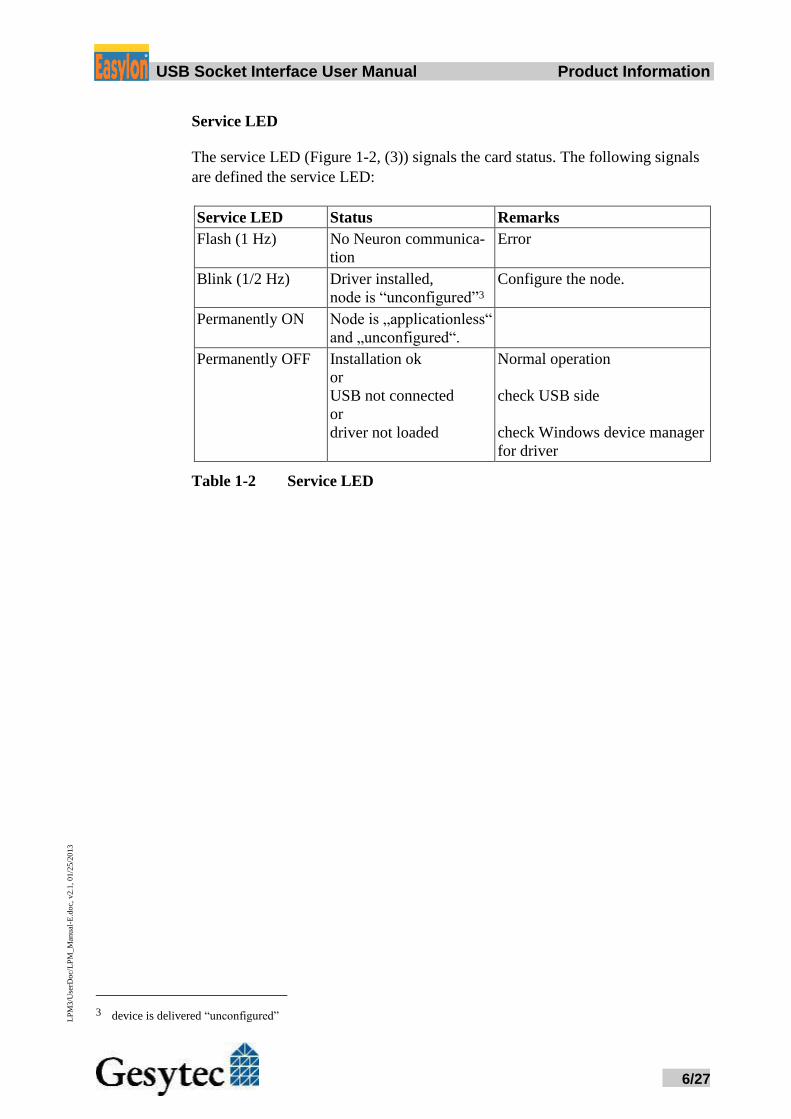
Service LED
The service LED (Figure 1-2, (3)) signals the card status. The following signals
are defined the service LED:
Service LED Status Remarks
Flash (1 Hz) No Neuron communica-
tion
Error
Blink (1/2 Hz) Driver installed,
node is “unconfigured”3
Configure the node.
Permanently ON Node is „applicationless“
and „unconfigured“.
Permanently OFF Installation ok
or
USB not connected
or
driver not loaded
Normal operation
check USB side
check Windows device manager
for driver
Table 1-2 Service LED
3 device is delivered “unconfigured”
Easylo USB Socket Interface User Manual Installation
7/27
LP
M3/U
serD
oc/
LP
M_M
anual
-E.d
oc,
v2.1
, 01/2
5/2
013
2 Installation Please check the delivered items. You must find the Easylon USB Socket Inter-
face and an installation CD, containing drivers and this documentation.
2.1 Hardware Installation
Please refer also to the manual describing the device into which you want to in-
sert the Easylon USB Socket Interface. Turn off power, open the device and plug
the USB module into a suitable USB socket. Please observer the following Pin
assignment. Restart the PC after the module has been installed and insert the
Drivers & Documentation CD in order to get the appropriate driver (cf. chapter
2.2 Driver Installation).
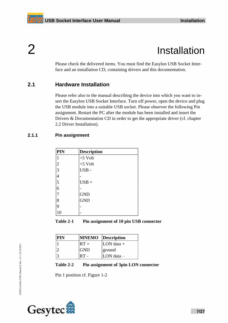
2.1.1 Pin assignment
PIN Description
1 +5 Volt
2 +5 Volt
3 USB -
4 -
5 USB +
6 -
7 GND
8 GND
9 -
10 -
Table 2-1 Pin assignment of 10 pin USB connector
PIN MNEMO Description
1 RT + LON data +
2 GND ground
3 RT - LON data –
Table 2-2 Pin assignment of 3pin LON connector
Pin 1 position cf. Figure 1-2
Easylo USB Socket Interface User Manual Installation
8/27
LP
M3/U
serD
oc/
LP
M_M
anual
-E.d
oc,
v2.1
, 01/2
5/2
013
2.2 Driver Installation
Drivers for different operating systems are available for the Easylon USB Socket
Interface. Currently these are Windows 2000, XP, Vista, 7 and 8 and the Win-
dows Server OS 2003, 2008 und 2008 R2. The drivers support both, the 32 and
the 64 bit version of these operating systems. Latest driver versions you can
download via the Easylon Support pages of our web site: www.gesytec.com.
A Linux driver is available in source code on request.
Windows operating systems section 2.2.1
Windows CE section 2.2.4
16-Bit driver under 32-bit Windows section 2.2.2
This section also describes in short the diagnosis utility „EasyCheck“ which can
be installed separately from CD.
2.2.1 Driver for Windows Operating System (WDM Drivers)
This section describes installation and setup of the Easylon Interface card drivers
for the Windows operating system from XP onwards.
The setup program is using the same WDM driver (Windows Driver Model) for
all operating systems.
Note: For installation you can either use the Windows assistant or the program
FastUpd.exe for manual installation, which is much more straightforward (cf.
chapter 2.2.1.2).
The latter is especially helpful if you are running Windows 7 and later or have to
install several instances of the driver.
2.2.1.1 Installation
Insert the Drivers & Documentation CD into the drive of your PC with the mod-
ule plugged into the desired socket.
The PC will show that a new USB device has been found. Windows will auto-
matically start the hardware wizard.
Easylo USB Socket Interface User Manual Installation
9/27
LP
M3/U
serD
oc/
LP
M_M
anual
-E.d
oc,
v2.1
, 01/2
5/2
013
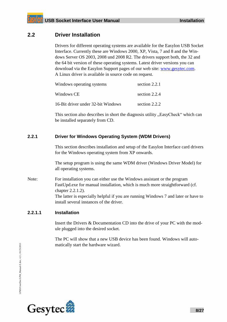
Windows systems up to and including XP
Choose not to browse Windows Update and click the Next> button to start the
driver installation using this assistant or Cancel and install manually (cf. chapter
2.2.1.2).
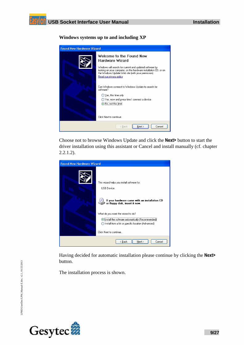
Having decided for automatic installation please continue by clicking the Next>
button.
The installation process is shown.
Easylo USB Socket Interface User Manual Installation
10/27
LP
M3/U
serD
oc/
LP
M_M
anual
-E.d
oc,
v2.1
, 01/2
5/2
013
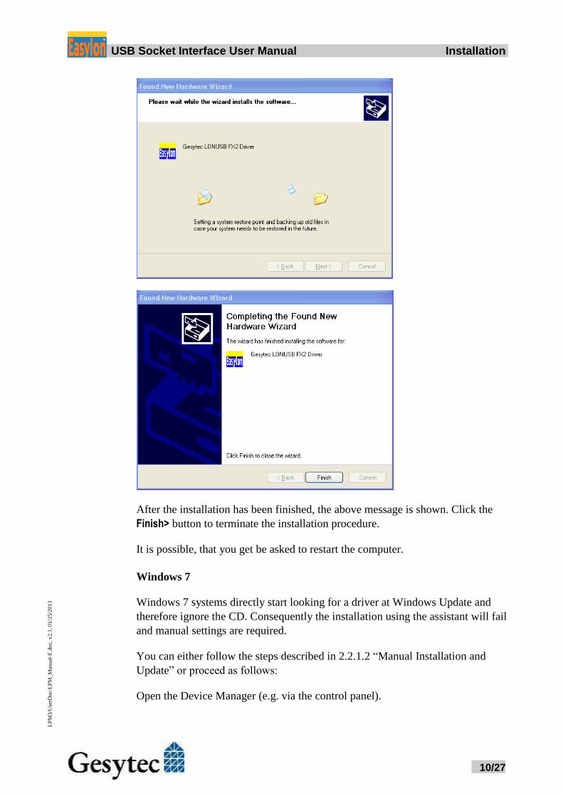
After the installation has been finished, the above message is shown. Click the
Finish> button to terminate the installation procedure.
It is possible, that you get be asked to restart the computer.
Windows 7
Windows 7 systems directly start looking for a driver at Windows Update and
therefore ignore the CD. Consequently the installation using the assistant will fail
and manual settings are required.
You can either follow the steps described in 2.2.1.2 “Manual Installation and
Update” or proceed as follows:
Open the Device Manager (e.g. via the control panel).
Easylo USB Socket Interface User Manual Installation
11/27
LP
M3/U
serD
oc/
LP
M_M
anual
-E.d
oc,
v2.1
, 01/2
5/2
013
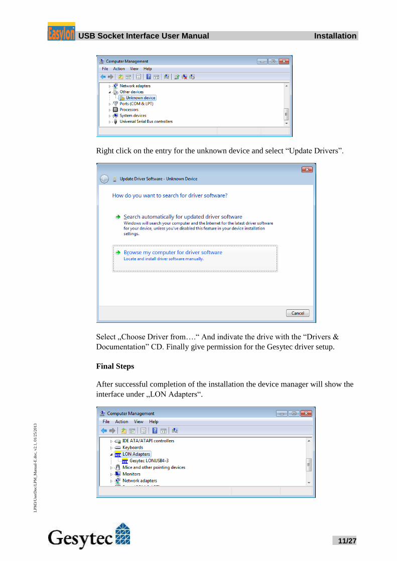
Right click on the entry for the unknown device and select “Update Drivers”.
Select „Choose Driver from….“ And indivate the drive with the “Drivers &
Documentation” CD. Finally give permission for the Gesytec driver setup.
Final Steps
After successful completion of the installation the device manager will show the
interface under „LON Adapters“.
Easylo USB Socket Interface User Manual Installation
12/27
LP
M3/U
serD
oc/
LP
M_M
anual
-E.d
oc,
v2.1
, 01/2
5/2
013
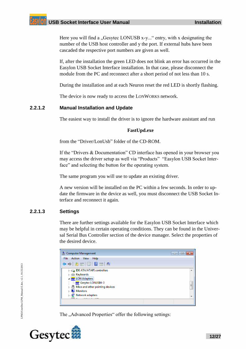
Here you will find a „Gesytec LONUSB x-y...“ entry, with x designating the
number of the USB host controller and y the port. If external hubs have been
cascaded the respective port numbers are given as well.
If, after the installation the green LED does not blink an error has occurred in the
Easylon USB Socket Interface installation. In that case, please disconnect the
module from the PC and reconnect after a short period of not less than 10 s.
During the installation and at each Neuron reset the red LED is shortly flashing.
The device is now ready to access the LONWORKS network.
2.2.1.2 Manual Installation and Update
The easiest way to install the driver is to ignore the hardware assistant and run
FastUpd.exe
from the “Driver/LonUsb” folder of the CD-ROM.
If the “Drivers & Documentation” CD interface has opened in your browser you
may access the driver setup as well via “Products” “Easylon USB Socket Inter-
face” and selecting the button for the operating system.
The same program you will use to update an existing driver.
A new version will be installed on the PC within a few seconds. In order to up-
date the firmware in the device as well, you must disconnect the USB Socket In-
terface and reconnect it again.
2.2.1.3 Settings
There are further settings available for the Easylon USB Socket Interface which
may be helpful in certain operating conditions. They can be found in the Univer-
sal Serial Bus Controller section of the device manager. Select the properties of
the desired device.
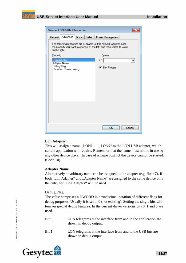
The „Advanced Properties“ offer the following settings:
Easylo USB Socket Interface User Manual Installation
13/27
LP
M3/U
serD
oc/
LP
M_M
anual
-E.d
oc,
v2.1
, 01/2
5/2
013
Lon Adapter
This will assign a name „LON1“ ... „LON9“ to the LON USB adapter, which
certain application will require. Remember that the name must not be in use by
any other device driver. In case of a name conflict the device cannot be started.
(Code 10).
Adapter Name
Alternatively an arbitrary name can be assigned to the adapter (e.g. floor 7). If
both „Lon Adapter“ and „Adapter Name“ are assigned to the same device only
the entry for „Lon Adapter“ will be used.
Debug Flag
The value comprises a DWORD in hexadecimal notation of different flags for
debug purposes. Usually it is set to 0 (not existing). Setting the single bits will
turn on special debug features. In the current driver versions bits 0, 1 and 3 are
used.
Bit 0: LON telegrams at the interface from and to the application are
shown in debug output.
Bit 1: LON telegrams at the interface from and to the USB bus are
shown in debug output.
Easylo USB Socket Interface User Manual Installation
14/27
LP
M3/U
serD
oc/
LP
M_M
anual
-E.d
oc,
v2.1
, 01/2
5/2
013
Bit 2: Reserved for Easylon Watcher.
Bit 3: CREATE and CLOSE) of the driver are displayed in the debug
output.
Note The debug output for instance can be displayed using the DebugView program,
which is freely available at www.sysinternals.com.
Permitted Power Saving
Usually the LON USB adapter allows a standby mode with applications running
(Standby). At certain conditions however, (e.g. LON USB using an external hub
under Windows 2000) the current supply to the LON USB adapter will be short-
ly interrupted during return from the standby mode by the external hub. Under
such conditions a standby mode must be turned off (None).
2.2.2 Windows and 16 Bit Applications
The Windows driver for the 32 bit Windows versions also provides a 16 bit inter-
face. (Unfortunately Microsoft does not support this in the 64 bit versions.) To
use it, the following entry has to be made in the file „config.nt“, usually found in
the windows\system32 directory:
Device=%SystemRoot%\system32\ lpxdos.exe –Llonusb1-2
The 32 bit LON device used is specified by the optional –L or /L parameter:
/Lname
name =
lonusb1-2 for device LONUSB at USB host controller 1
and with port number 2 at USB root. If several
hubs have been cascaded the respective port
numbers have to be provided as well.
Note: Two subsequent “l” characters have to be entered, one indicating the parameter -
L, the second as first character of the name: –Llxxxx
The 16 bit LON device used is specified by the following optional parameter:
/Dn
with n = 1...9 for LON1 to LON9
Without this parameter, the interface will be assigned the first unused name start-
ing with “LON1”.
Easylo USB Socket Interface User Manual Installation
15/27
LP
M3/U
serD
oc/
LP
M_M
anual
-E.d
oc,
v2.1
, 01/2
5/2
013
2.2.3 EasyCheck – Quick Interface Diagnosis
In addition to the drivers, the test utility “EasyCheck” can be installed in the re-
spective program directory (default: : \Easylon\Lpx ). The program checks inter-
face and software environment and displays information, from which can be
concluded on the reasons for problems in connection with the interface.
The program “EasyCheck” runs an analysis of the system’s software. It will open
the selected interface, check the driver version and display it. By sending a “que-
ry status” command the communication with the hardware is tested. Using the
“read memory” command the utility will show if the device is running MIP or
NSI firmware. Properly installed Easylon Interfaces will send a corresponding
answer.
2.2.4 Windows CE Driver
The Windows CE driver has been designed for x86 processors. It is available for
other processors on request. There are versions for Windows up to CE 6.0. It can
be installed in two ways:
To install the driver in CE devices with static RAM copy the LonUsb.dll into the
\Windows directory and adjust registry. The required files can be found on the
Driver & Documentation CD under Windows CE/4.2-6.0/LonUsb.
2.2.4.1 Copy .dll to Windows Directory
Copy the device driver file lonusb.dll to the \Windows directory of your
hardware system.
Modify Windows CE registry by means of an registry editor adding the fol-
lowing lines:
; LONUSB - Driver
[HKEY_LOCAL_MACHINE\Drivers\USB\LoadClients\3596\Default
\Default\LonUsb]
"DLL"="lonusb.dll"
"Prefix"="LON"
"DebugFlag"=dword:0
"ReadTimeout"=dword:FFFFFFFF
These lines are provided in the file LonUsb.reg.
2.2.4.2 Integration into Windows CE Image
This section describes the integration of the Windows CE driver for the Easylon
USB Socket Interface in a Windows CE system. This procedure requires the
Windows CE Platform Builder.
Please check for the following requirements to ensure that USB is supported:
Easylo USB Socket Interface User Manual Installation
16/27
LP
M3/U
serD
oc/
LP
M_M
anual
-E.d
oc,
v2.1
, 01/2
5/2
013
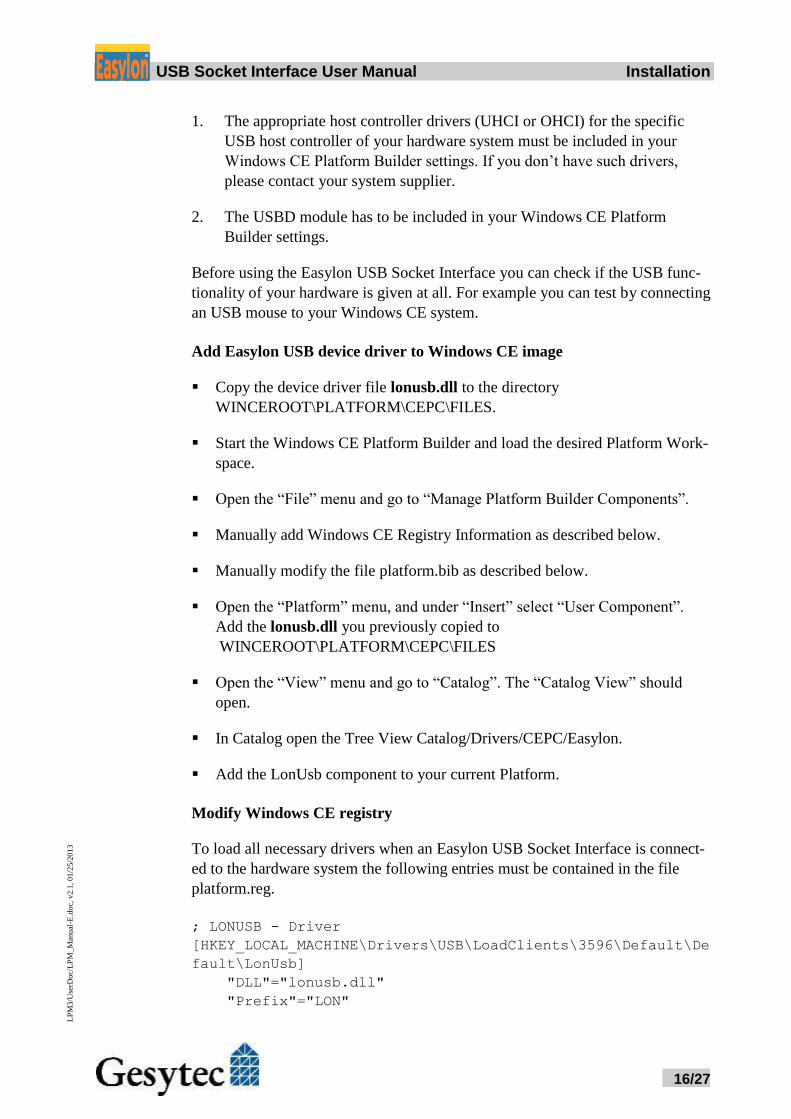
1. The appropriate host controller drivers (UHCI or OHCI) for the specific
USB host controller of your hardware system must be included in your
Windows CE Platform Builder settings. If you don’t have such drivers,
please contact your system supplier.
2. The USBD module has to be included in your Windows CE Platform
Builder settings.
Before using the Easylon USB Socket Interface you can check if the USB func-
tionality of your hardware is given at all. For example you can test by connecting
an USB mouse to your Windows CE system.
Add Easylon USB device driver to Windows CE image
Copy the device driver file lonusb.dll to the directory
WINCEROOT\PLATFORM\CEPC\FILES.
Start the Windows CE Platform Builder and load the desired Platform Work-
space.
Open the “File” menu and go to “Manage Platform Builder Components”.
Manually add Windows CE Registry Information as described below.
Manually modify the file platform.bib as described below.
Open the “Platform” menu, and under “Insert” select “User Component”.
Add the lonusb.dll you previously copied to
WINCEROOT\PLATFORM\CEPC\FILES
Open the “View” menu and go to “Catalog”. The “Catalog View” should
open.
In Catalog open the Tree View Catalog/Drivers/CEPC/Easylon.
Add the LonUsb component to your current Platform.
Modify Windows CE registry
To load all necessary drivers when an Easylon USB Socket Interface is connect-
ed to the hardware system the following entries must be contained in the file
platform.reg.
; LONUSB - Driver
[HKEY_LOCAL_MACHINE\Drivers\USB\LoadClients\3596\Default\De
fault\LonUsb]
"DLL"="lonusb.dll"
"Prefix"="LON"
Easylo USB Socket Interface User Manual Installation
17/27
LP
M3/U
serD
oc/
LP
M_M
anual
-E.d
oc,
v2.1
, 01/2
5/2
013
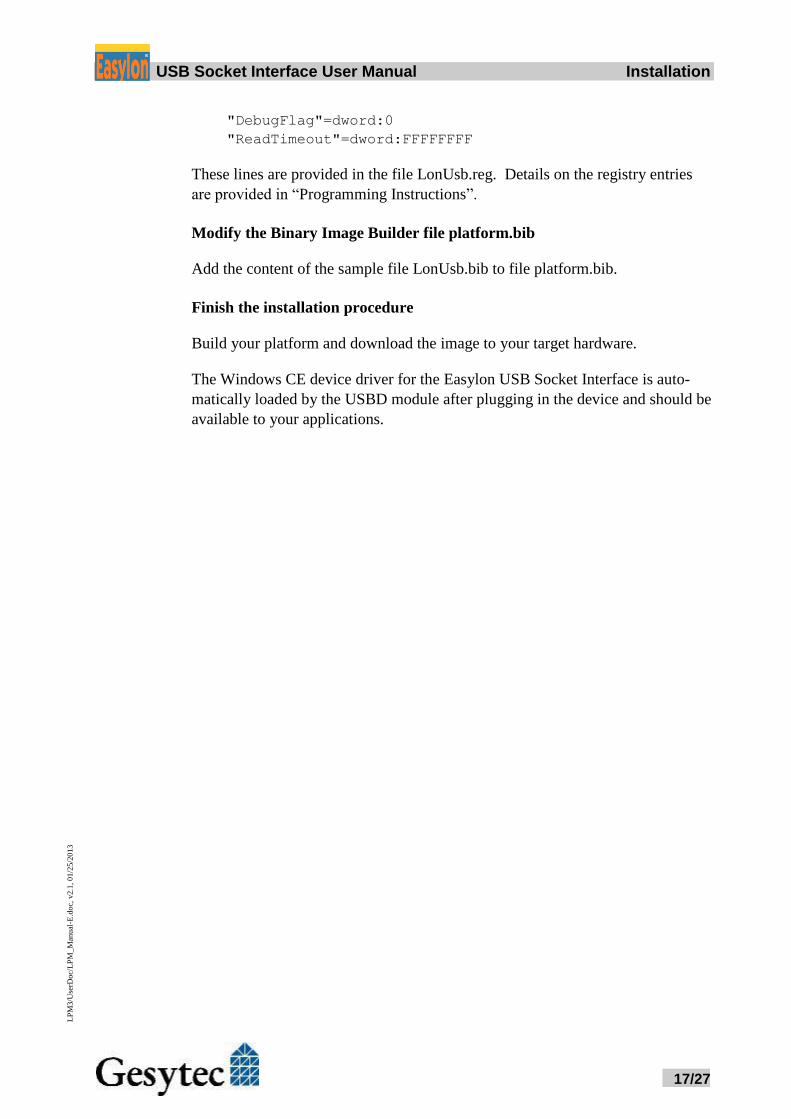
"DebugFlag"=dword:0
"ReadTimeout"=dword:FFFFFFFF
These lines are provided in the file LonUsb.reg. Details on the registry entries
are provided in “Programming Instructions”.
Modify the Binary Image Builder file platform.bib
Add the content of the sample file LonUsb.bib to file platform.bib.
Finish the installation procedure
Build your platform and download the image to your target hardware.
The Windows CE device driver for the Easylon USB Socket Interface is auto-
matically loaded by the USBD module after plugging in the device and should be
available to your applications.
Easylo USB Socket Interface User Manual Technical Specifications
18/27
LP
M3/U
serD
oc/
LP
M_M
anual
-E.d
oc,
v2.1
, 01/2
5/2
013
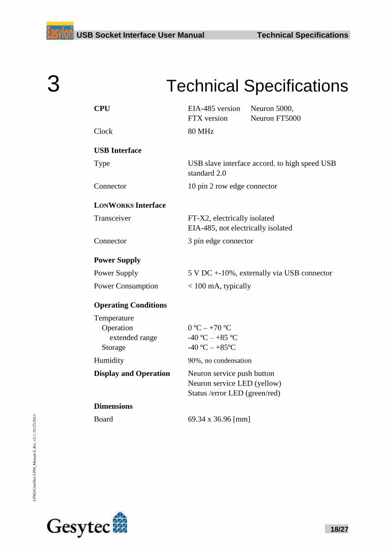
3 Technical Specifications CPU EIA-485 version Neuron 5000,
FTX version Neuron FT5000
Clock 80 MHz
USB Interface
Type USB slave interface accord. to high speed USB
standard 2.0
Connector 10 pin 2 row edge connector
LONWORKS Interface
Transceiver FT-X2, electrically isolated
EIA-485, not electrically isolated
Connector 3 pin edge connector
Power Supply
Power Supply 5 V DC +-10%, externally via USB connector
Power Consumption < 100 mA, typically
Operating Conditions
Temperature
Operation 0 ºC – +70 ºC
extended range -40 ºC – +85 ºC
Storage -40 ºC – +85ºC
Humidity 90%, no condensation
Display and Operation Neuron service push button
Neuron service LED (yellow)
Status /error LED (green/red)
Dimensions
Board 69.34 x 36.96 [mm]
Easylo USB Socket Interface User Manual Technical Specifications
19/27
LP
M3/U
serD
oc/
LP
M_M
anual
-E.d
oc,
v2.1
, 01/2
5/2
013
559
43
2
24
22
36
96
6396
32
68
420
6592
6934
82
6
1/100 mm
Ø 320
Ø 3202
41
3
6350
1 2
12
30
5,20
1
1/100 mm8,8
43
010
20 15
0
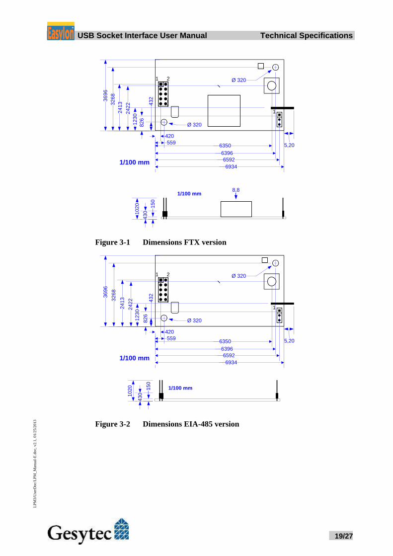
Figure 3-1 Dimensions FTX version
559
43
2
24
22
36
96
6396
32
68
420
6592
6934
82
6
1/100 mm
Ø 320
Ø 320
24
13
6350
1 2
12
30
5,20
1
1/100 mm
43
010
20 15
0
Figure 3-2 Dimensions EIA-485 version
Easylo USB Socket Interface User Manual Programming Instructions
20/27
LP
M3/U
serD
oc/
LP
M_M
anual
-E.d
oc,
v2.1
, 01/2
5/2
013
4 Programming Instructions
4.1 Windows CE Application Interface
Note: Some of the functions described below are marked “obsolete”. These functions
and control codes are referenced her only for compatibility with older versions of
LPCDRV/LG2DRV and should not be used for development of new software.
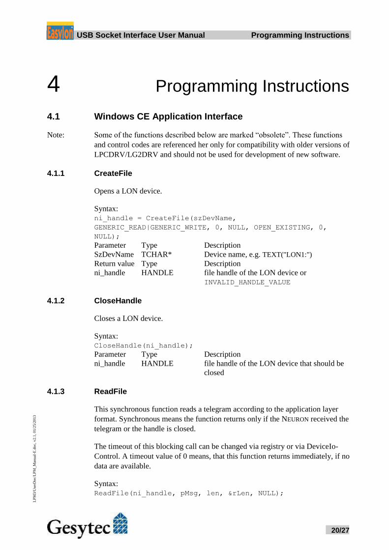
4.1.1 CreateFile
Opens a LON device.
Syntax:
ni_handle = CreateFile(szDevName,
GENERIC_READ|GENERIC_WRITE, 0, NULL, OPEN_EXISTING, 0,
NULL);
Parameter Type Description
SzDevName TCHAR* Device name, e.g. TEXT("LON1:")
Return value Type Description
ni_handle HANDLE file handle of the LON device or
INVALID_HANDLE_VALUE
4.1.2 CloseHandle
Closes a LON device.
Syntax:
CloseHandle(ni_handle);
Parameter Type Description
ni_handle HANDLE file handle of the LON device that should be
closed
4.1.3 ReadFile
This synchronous function reads a telegram according to the application layer
format. Synchronous means the function returns only if the NEURON received the
telegram or the handle is closed.
The timeout of this blocking call can be changed via registry or via DeviceIo-
Control. A timeout value of 0 means, that this function returns immediately, if no
data are available.
Syntax:
ReadFile(ni_handle, pMsg, len, &rLen, NULL);
Easylo USB Socket Interface User Manual Programming Instructions
21/27
LP
M3/U
serD
oc/
LP
M_M
anual
-E.d
oc,
v2.1
, 01/2
5/2
013
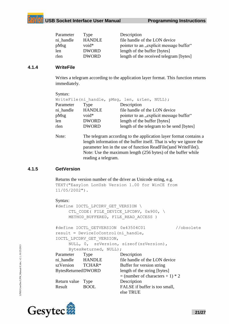
Parameter Type Description
ni_handle HANDLE file handle of the LON device
pMsg void* pointer to an „explicit message buffer“
len DWORD length of the buffer [bytes]
rlen DWORD length of the received telegram [bytes]
4.1.4 WriteFile
Writes a telegram according to the application layer format. This function returns
immediately.
Syntax:
WriteFile(ni_handle, pMsg, len, &rLen, NULL);
Parameter Type Description
ni_handle HANDLE file handle of the LON device
pMsg void* pointer to an „explicit message buffer“
len DWORD length of the buffer [bytes]
rlen DWORD length of the telegram to be send [bytes]
Note: The telegram according to the application layer format contains a
length information of the buffer itself. That is why we ignore the
parameter len in the use of function ReadFile()and WriteFile().
Note: Use the maximum length (256 bytes) of the buffer while
reading a telegram.
4.1.5 GetVersion
Returns the version number of the driver as Unicode string, e.g.
TEXT("Easylon LonUsb Version 1.00 for WinCE from
11/05/2002").
Syntax:
#define IOCTL_LPCDRV_GET_VERSION \
CTL_CODE( FILE_DEVICE_LPCDRV, 0x900, \
METHOD_BUFFERED, FILE_READ_ACCESS )
#define IOCTL_GETVERSION 0x43504C01 //obsolete
result = DeviceIoControl(ni_handle,
IOCTL_LPCDRV_GET_VERSION,
NULL, 0, szVersion, sizeof(szVersion),
BytesReturned, NULL);
Parameter Type Description
ni_handle HANDLE file handle of the LON device
szVersion TCHAR* Buffer for version string
BytesReturned DWORD length of the string [bytes]
= (number of characters + 1) * 2
Return value Type Description
Result BOOL FALSE if buffer is too small,
else TRUE
Easylo USB Socket Interface User Manual Programming Instructions
22/27
LP
M3/U
serD
oc/
LP
M_M
anual
-E.d
oc,
v2.1
, 01/2
5/2
013
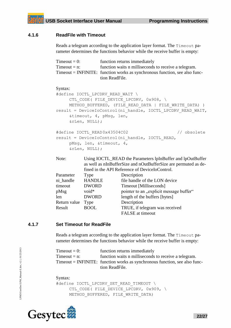
4.1.6 ReadFile with Timeout
Reads a telegram according to the application layer format. The Timeout pa-
rameter determines the functions behavior while the receive buffer is empty:
Timeout = 0: function returns immediately
Timeout = n: function waits n milliseconds to receive a telegram.
Timeout = INFINITE: function works as synchronous function, see also func-
tion ReadFile.
Syntax:
#define IOCTL_LPCDRV_READ_WAIT \
CTL_CODE( FILE_DEVICE_LPCDRV, 0x908, \
METHOD_BUFFERED, (FILE_READ_DATA | FILE_WRITE_DATA) )
result = DeviceIoControl(ni_handle, IOCTL_LPCDRV_READ_WAIT,
&timeout, 4, pMsg, len,
&rLen, NULL);
#define IOCTL_READ 0x43504C02 // obsolete
result = DeviceIoControl(ni_handle, IOCTL_READ,
pMsg, len, &timeout, 4,
&rLen, NULL);
Note: Using IOCTL_READ the Parameters lpInBuffer and lpOutBuffer
as well as nInBufferSize and nOutBufferSize are permuted as de-
fined in the API Reference of DeviceIoControl.
Parameter Type Description
ni_handle HANDLE file handle of the LON device
timeout DWORD Timeout [Milliseconds]
pMsg void* pointer to an „explicit message buffer“
len DWORD length of the buffers [bytes]
Return value Type Description
Result BOOL TRUE, if telegram was received
FALSE at timeout
4.1.7 Set Timeout for ReadFile
Reads a telegram according to the application layer format. The Timeout pa-
rameter determines the functions behavior while the receive buffer is empty:
Timeout = 0: function returns immediately
Timeout = n: function waits n milliseconds to receive a telegram.
Timeout = INFINITE: function works as synchronous function, see also func-
tion ReadFile.
Syntax:
#define IOCTL_LPCDRV_SET_READ_TIMEOUT \
CTL_CODE( FILE_DEVICE_LPCDRV, 0x909, \
METHOD_BUFFERED, FILE_WRITE_DATA)
Easylo USB Socket Interface User Manual Programming Instructions
23/27
LP
M3/U
serD
oc/
LP
M_M
anual
-E.d
oc,
v2.1
, 01/2
5/2
013
result = DeviceIoControl(ni_handle, IOCTL_LPCDRV_READ_WAIT,
&timeout, 4, NULL, 0,
&rLen, NULL);
Parameter Type Description
ni_handle HANDLE file handle of the LON device
timeout DWORD Timeout [Milliseconds]
Return value Type Description
Result BOOL TRUE, if timeout was stored,
FALSE if an error has occurred
Note: Undefined IOCTL-Codes will return FALSE and set LastError to
ERROR_NOT_SUPPORTED.
4.1.8 Registry entries for Easylon USB Interface ; LONUSB - Driver
[HKEY_LOCAL_MACHINE\Drivers\USB\LoadClients\3596\Default\De
fault\LonUsb]
"DLL"="lonusb.dll"
"Prefix"="LON"
"DebugFlag"=dword:0
"ReadTimeout"=dword:FFFFFFFF
DebugFlag
The value comprises a DWORD in hexadecimal notation of different flags
for debug purposes. Usually it is set to 0 (not existing). Setting the single
bits will turn on special debug features. In the current driver versions bits 0
and 1 are used.
Bit 0: LON telegrams at the interface from and to the application
are shown in debug output.
Bit 1: LON telegrams at the interface from and to the USB bus are
shown in debug output.
ReadTimeout
The value (in milliseconds) comprises a DWORD in hexadecimal notation
to affect the behavior of ReadFile().
A value of INFINITE (= 0xffffffff) makes ReadFile() a blocking call. This
is the default behavior, if no parameter is given (like lpcdrv, lg2drv).
A timeout value of 0 means, that this function returns immediately, if no da-
ta are available.
Easylo USB Socket Interface User Manual Tips and Tricks
24/27
LP
M3/U
serD
oc/
LP
M_M
anual
-E.d
oc,
v2.1
, 01/2
5/2
013
5 Tips and Tricks
5.1 Hot Plugging
The Easylon USB Socket Interface may be connected and disconnected, when
the PC is already running. Windows recognizes plugging the device in and starts
the driver automatically. You should not remove the device, when an application
is using it.
5.2 Using an USB Hub
Of course the Easylon USB Socket Interface can be used with an USB hub. If
there are a couple of USB devices active, the communication between PC and
Easylon USB Socket Interface may be slowed down.
5.3 Standby Mode of PC
A PC with connected Easylon USB Socket Interface may be set to standby mode,
because the device will be powered during standby. However, if the device is
used with an external USB hub under Windows 2000, it was observed that, at re-
turning from the standby mode, some hubs shortly interrupt of the power supply
to the Easylon USB Interface. This USB hub behavior will reinitialize the device
and active applications, using the Easylon USB Socket Interface before entering
standby mode, are not able to communicate with device any longer.
In such configurations please refer to section Settings and set “Permitted Power
Saving" to “None” to disable the standby mode. The LON USB driver will then
inhibit the standby mode with applications running.
5.4 Hibernation Mode of PC
The Easylon USB Socket Interface does not support the hibernation mode. When
the PC enters hibernation mode, the USB will not be powered any longer. As this
would lead to a loss of the Neuron Chip settings the LON USB driver will inhibit
Windows from turning into the hibernation mode with applications running.
Easylo USB Socket Interface User Manual Tips and Tricks
25/27
LP
M3/U
serD
oc/
LP
M_M
anual
-E.d
oc,
v2.1
, 01/2
5/2
013
5.5 Registry Key
The driver of the Easylon USB Socket Interface makes an entry in the registry
database for each found device, according to Echelon’s guidelines. You will find
this entry at:
\\HKEY_LOCAL_MACHINE\Software\LonWorks\DeviceDrivers.
For each Easylon USB Socket Interface you will find a key with the device name
(Gesytec LONUSBx-y...) and a character value with the driver name.
Easylo USB Socket Interface User Manual Lists of Fugures and Tables
26/27
LP
M3/U
serD
oc/
LP
M_M
anual
-E.d
oc,
v2.1
, 01/2
5/2
013
6 List of Figures Figure 1-1 Easylon USB Socket Interface FT-X1 and EIA-485 ......................................... 4
Figure 1-2 Module components shown for FTX variant ..................................................... 5
Figure 3-1 Dimensions FTX version ................................................................................. 19
Figure 3-2 Dimensions EIA-485 version ........................................................................... 19
7 List of Tables Table 1-1 Variants and order-codes of Easylon USB Socket Interfaces ............................ 4
Table 1-2 Service LED ....................................................................................................... 6
Table 2-1 Pin assignment of 10 pin USB connector .......................................................... 7
Table 2-2 Pin assignment of 3pin LON connector ............................................................. 7
Easylo USB Socket Interface User Manual Index
27/27
LP
M3/U
serD
oc/
LP
M_M
anual
-E.d
oc,
v2.1
, 01/2
5/2
013
8 Index
16 bit applications 14
adapter settings 12
connector 18
connector, pin assignment 5
debug flag 13
DebugFlag 23
dimension 18, 19
dirver 4
EasyCheck 15
firmware 4
hibernate mode 24
hot plugging 24
installation 7
LED 5, 18
OPC server 5
order code 4
power consumption 18
power supply 18
product information 4
programming instructions 20
ReadTimeout 23
registry key 25
scope of delivery 4
service LED 6
standby 14
standby mode 24
technical specifications 18
temperature 18
tips and tricks 24
transceiver 18
USB hub 24
USB standard 5
variants 4
Windows
2000 14
7 8, 10
CE 15
Vista 14
XP 14
Windows CE
application interface 20
driver installation 15
WLDV32.DLL 5


![chiliboard DATASHEET - TME · chiliboard datasheet v1.0 7 2.4.3. USB type A [ J3 ] The chiliSOM supports two USB OTG host ports. The chiliboard is equipped with USB type A socket](https://img.pdfslide.net/doc/110x75/5f87512a96e83e0fac241dc8/chiliboard-datasheet-tme-chiliboard-datasheet-v10-7-243-usb-type-a-j3-.jpg)