Embed Size (px)
Citation preview


ENERGY CONSERVATION BUILDING CODE (ECBC)
USER GUIDE
July 2009
Energy Conservation Building Code User Guide
© 2009 Bureau of Energy Efficiency
Published by: Bureau of Energy Efficiency
4th Floor, Sewa Bhawan, R. K.Puram, New Delhi, India
Developed by: USAID ECO-III Project
International Resources Group2, Balbir Saxena Marg, Hauz Khas, New Delhi, India
No portion (graphics or text) of this report may be reproduced, translated, or transmitted in any form or manner by any means—including but not limited to electronic copy, photocopy, or any other informational storage and retrieval system without explicit written consent from Bureau of Energy Efficiency, New Delhi.
All rights reservedPrinted in New Delhi, IndiaISBN No. 978-81-909025-3-3
July 2009
This report is made possible by the generous support of the U.S. Government through the ECO-III Project to the Indian Government. The views expressed in this report do not necessarily reflect the views of partner countries – United States of America and India – or the United States Agency for International Development.

USAID ECO-III ProjectThe Energy Conservation and Commercialization (ECO) Program was signed between the Government of India (GOI) and USAID in January 2000 under a bilateral agreement with the objective to enhance commercial viability and performance of Indian energy sector and to promote utilization of clean and energy-efficient technologies in the sector.
Following the enactment of the Energy Conservation Act 2001, ECO-I Project supported GOI in the establishment of the Bureau of Energy Efficiency (BEE). Support to BEE was provided to set up procedures and authorities, establish office facilities and assist in several activities leading to the development of BEE’s Action Plan including thrust area such as the development of an energy auditor certification program.
ECO-II Project provided BEE with necessary technical assistance and training support to implement three thrust areas of the Action Plan. The first area was to develop the Energy Conservation Building Codes (ECBC) for the five climatic zones of India, the second was to support Maharashtra Energy Development Agency in developing strategies for energy conservation and implementation of selected programs, and the third area focused on implementing a pilot DSM program to replace incandescent lamps with CFLs in the state of Karnataka in partnership with BESCOM.
Since November 2006, International Resources Group (IRG), with support from its partners IRG Systems South Asia, Alliance to Save Energy and DSCL Energy Services, other partner organizations and consultants has been implementing the ECO-III Project by working closely with BEE, Gujarat Energy Development Agency, and Punjab Energy Development Agency.
ECBC User Guide has been produced to assist Government of India in the implementation of ECBC, which was launched by Ministry of Power in May 2007. It is hoped that this document will help in creating awareness and enhancing understanding about the ECBC. ECO-III Project has developed Tip Sheets and Design Guides in the past to help in the ECBC implementation efforts. More information as well as electronic copies of all the publications can be accessed at www.eco3.org.

ForewordThe Energy Conservation Act, 2001(52 of 2001) empowers the Central Government under Section 14(p) read with Section 56(2)(l) to prescribe Energy Conservation Building Code (ECBC). The Code defines norms and standards for the energy performance of buildings and their components based on the climate zone in which they are located.
Under the leadership of Bureau of Energy Efficiency (BEE), a Committee of Experts finalized ECBC in consultation with various Stakeholders in 2007, with an overall purpose to provide minimum requirements for the energy-efficient design and construction of buildings. ECBC covers building envelope, heating, ventilation, and air conditioning system, interior and exterior lighting system, service hot water, electrical power system and motors.
In May 2007, the Ministry of Power, Government of India formally launched the ECBC for its voluntary adoption in the country. Since then, BEE has been promoting and facilitating its adoption through several training and capacity building programmes. BEE is also monitoring implementation of ECBC through the ECBC Programme Committee (EPC). EPC also reviews periodically the inconsistencies and comments on ECBC received from various quarters. In this context, BEE in consultation with EPC and support from USAID ECO-III Project brought out a revised version of ECBC in May 2008.
During the capacity building effort, a need was clearly felt to provide additional guidance to design and construction professionals on the rationale behind the ECBC specifications and provide explanations to the key terms and concepts governing these specifications so that people are able to comprehend ECBC in a better way. Considering this growing need for developing a better understanding of ECBC in the country, the ECBC User Guide has been prepared under the USAID ECO-III Project in close partnership with BEE. The document aims to guide and assist the building designers, architects and all others involved in the building construction industry to implement ECBC in real situations. The document is written both as a reference and as an instructional guide. It also features examples, best practices, checklists, etc. to direct and facilitate the design and construction of ECBC-compliant buildings in India.
I am happy to note that the ECBC User Guide Development Team has made a concerted effort to provide all the information, especially minimum performance standards that buildings need to comply with, in one place. Consequently, it is my hope that users of ECBC trying to show compliance through the prescriptive path will find it easier to do so through the guidance provided in the document. The ECBC User Guide also provides additional guidance on the Whole Building Performance method by making references to international publications that are widely used by the building design community.
I thank the entire ECBC User Guide Development Team, led by Dr. Satish Kumar, for its extensive efforts in bringing out this document. I would like to express my sincere appreciation to the USAID for providing this technical assistance under the ECO-III Project and to the International Resources Group for spearheading this team effort.
17th July, 2009 (Dr. Ajay Mathur)

ECBC User Guide Development TeamSatish Kumar, Team Leader
IRG, USAID ECO-III Project
Aleisha Khan, Alliance to Save Energy•
Anurag Bajpai, IRG, USAID ECO-III Project •
G. S. Rao, Team Catalyst•
Jyotirmay Mathur, Malviya National Institute • Technology
Laurie Chamberlain, International Resources • Group (IRG)
P. C. Thomas, Team Catalyst•
Rajan Rawal, Center for Environmental Planning • and Technology
Ravi Kapoor, IRG, USAID ECO-III Project•
Surekha Tetali, International Institute of • Information Technology
Vasudha Lathey•
Vishal Garg, International Institute of • Information Technology

Acknowledgements
Energy Conservation Building Code (ECBC) User Guide, developed by the USAID ECO-III Project in association with Bureau of Energy Efficiency (BEE) aims to support the implementation of ECBC.
I would like to thank Dr. Archana Walia, Project Manager, and Mr. S. Padmanaban of USAID for their constant encouragement and steadfast support during the development process. I would like to acknowledge the tremendous support and encouragement provided by Dr. Ajay Mathur, Director General, and Mr. Sanjay Seth, Energy Economist of BEE in the preparation of the Guide.
A substantial undertaking of this nature would not have been possible without the extremely valuable technical contribution provided by the Development Team of ECBC User Guide especially Ms. Vasudha Lathey, Ms. Aleisha Khan of Alliance to Save Energy (ASE), Dr. Vishal Garg and Ms. Surekha Tetali of International Institute of Information Technology (IIIT), Prof. Rajan Rawal of Center for Environmental Planning and Technology (CEPT), Dr. Jyotirmay Mathur of Malviya National Institute Technology (MNIT), Mr. P. C. Thomas and Mr. G. S. Rao of Team Catalyst.
I would like to acknowledge the assistance that the Development Team received from the American Society of Heating, Refrigerating and Air-Conditioning Engineers (ASHRAE) Inc., USA. The 90.1 User Manual, ANSI/ASHRAE/IESNA Standard 90.1-2004, provided us with a robust framework and a sound technical reference during the development of the ECBC User Guide. I am also thankful to Ms. Meredydd Evans of Pacific North-West National Laboratory (PNNL), and to Saint Gobain, DuPont, ASAHI-India, and Dr. Mahabir Bhandari (DesignBuilder) for providing inputs on many iterations of this document.
I would like to convey my special thanks to the ECO-III Project Team – Mr. Ravi Kapoor for his substantial technical contribution to the development of the entire document, Mr. Anurag Bajpai for his tireless efforts in coordinating inputs from the Development Team members, and Ms. Meetu Sharma for her persistence efforts to prepare the graphics and desktop layout of multiple iterations of the document. Without the perseverance and discipline of ECO-III Project Team this work would not have been possible. I also like to thank Ms. Laurie Chamberlain of International Resources Group (IRG) HQ for assisting us in carrying out technical editing of this document.
17th July, 2009 (Dr. Satish Kumar) Chief of Party, USAID ECO-III Project International Resources Group
How to Use This Guide
The ECBC User Guide follows the same structure as the Energy Conservation Building Code. Consequently, Chapters 1 through 8 and Appendix A through G are identical to the ECBC chapters and the sections within each chapter also follow the ECBC. Appendix B provides detailed guidance on the Whole Building Performance method. Assumptions that can be standardized have been included to reduce the chances of gamesmanship and to create a framework that would allow for “apples to apples” comparison across different projects while creating simulation models for Standard and Proposed Design. Appendix E is about Climate Zones in India. This appendix provides a summary of each of the five climate zones and another table that provides a listing of major Indian cities along with its climatic zone. A new Appendix H has been included that provides a comparison of International Building Energy Standards. Apart from comparing some of the technical specifications, this appendix also provides the different approaches taken by countries to check code compliance and enforcement. It is hoped that this section will provide some ideas to the policy makers on how to make ECBC compliance mandatory so that minimum energy efficiency performance can be met by buildings coming under the scope of ECBC.
The ECBC User Guide has been designed in an easy to understand format. The document uses a consistent format and provides guidance at the following three levels:
Text that is shown in Bluea)
This text is a direct excerpt from the ECBC document and is likely to serve as an anchor for many of the guidance text and examples included in different chapters. Users interested in showing ECBC compliance should pay close attention to the text drawn from ECBC and shown in blue. Examples of ECBC text and ECBC table are reproduced below for guidance:
The Code is applicable to buildings or building complexes that have a connected load of 500 kW or greater or a contract demand of 600 kVA or greater.
Window Wall Ratio Minimum VLT0 - 0.3 0.27
0.31-0.4 0.20
Boxed Text showing Tips, Frequently Asked Questions (FAQ), Examples, etc.b)
The Boxed Text provides guidance to the users for better understanding of ECBC concepts and ECBC applicability in different situations. An example of Boxed Text is shown below:
: Role of Climate ZoneBox 1-A: The ECBC building envelope requirements are based on the climate zone in which the building is located. ECBC defines five climate zones (hot-dry; warm-humid; composite; temperate; cold), which are distinctly unique in their weather profiles (Appendix E). Based on the characteristics of climate, the thermal comfort requirements in buildings and their physical manifestation in architectural form are also different for each climate zone
Normal text in blackc)
This type of text forms the core of the ECBC User Guide and provides overall guidance on how best to understand and apply ECBC.
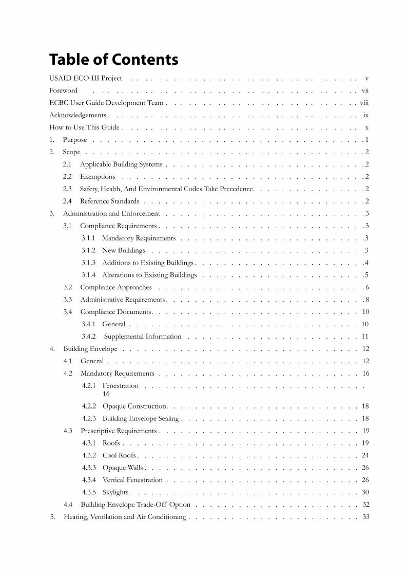
Table of ContentsUSAID ECO-III Project . . . . . . . . . . . . . . . . . . . . . . . . . . . . . . . . v
Foreword . . . . . . . . . . . . . . . . . . . . . . . . . . . . . . . . . . . . . vii
ECBC User Guide Development Team . . . . . . . . . . . . . . . . . . . . . . . . . . . viii
Acknowledgements . . . . . . . . . . . . . . . . . . . . . . . . . . . . . . . . . . . ix
How to Use This Guide . . . . . . . . . . . . . . . . . . . . . . . . . . . . . . . . . x
Purpose1. . . . . . . . . . . . . . . . . . . . . . . . . . . . . . . . . . . . . . . 1
Scope2. . . . . . . . . . . . . . . . . . . . . . . . . . . . . . . . . . . . . . . . 2
Applicable Building Systems2.1 . . . . . . . . . . . . . . . . . . . . . . . . . . . . 2
Exemptions2.2 . . . . . . . . . . . . . . . . . . . . . . . . . . . . . . . . . . 2
Safety, Health, And Environmental Codes Take Precedence2.3 . . . . . . . . . . . . . . . . 2
Reference Standards2.4 . . . . . . . . . . . . . . . . . . . . . . . . . . . . . . . 2
Administration and Enforcement3. . . . . . . . . . . . . . . . . . . . . . . . . . . . . 3
Compliance Requirements3.1 . . . . . . . . . . . . . . . . . . . . . . . . . . . . . 3
Mandatory Requirements3.1.1 . . . . . . . . . . . . . . . . . . . . . . . . . . 3
New Buildings3.1.2 . . . . . . . . . . . . . . . . . . . . . . . . . . . . . . 3
Additions to Existing Buildings3.1.3 . . . . . . . . . . . . . . . . . . . . . . . .4
Alterations to Existing Buildings3.1.4 . . . . . . . . . . . . . . . . . . . . . . . 5
Compliance Approaches3.2 . . . . . . . . . . . . . . . . . . . . . . . . . . . . . 6
Administrative Requirements3.3 . . . . . . . . . . . . . . . . . . . . . . . . . . . . 8
Compliance Documents3.4 . . . . . . . . . . . . . . . . . . . . . . . . . . . . . 10
General3.4.1 . . . . . . . . . . . . . . . . . . . . . . . . . . . . . . . . 10
Supplemental Information3.4.2 . . . . . . . . . . . . . . . . . . . . . . . . 11
Building Envelope4. . . . . . . . . . . . . . . . . . . . . . . . . . . . . . . . . . 12
General4.1 . . . . . . . . . . . . . . . . . . . . . . . . . . . . . . . . . . . 12
Mandatory Requirements4.2 . . . . . . . . . . . . . . . . . . . . . . . . . . . . 16
Fenestration4.2.1 . . . . . . . . . . . . . . . . . . . . . . . . . . . . . . . 16
Opaque Construction4.2.2 . . . . . . . . . . . . . . . . . . . . . . . . . . . 18
Building Envelope Sealing4.2.3 . . . . . . . . . . . . . . . . . . . . . . . . . 18
Prescriptive Requirements4.3 . . . . . . . . . . . . . . . . . . . . . . . . . . . . 19
Roofs4.3.1 . . . . . . . . . . . . . . . . . . . . . . . . . . . . . . . . . 19
Cool Roofs4.3.2 . . . . . . . . . . . . . . . . . . . . . . . . . . . . . . . 24
Opaque Walls4.3.3 . . . . . . . . . . . . . . . . . . . . . . . . . . . . . . 26
Vertical Fenestration4.3.4 . . . . . . . . . . . . . . . . . . . . . . . . . . . 26
Skylights4.3.5 . . . . . . . . . . . . . . . . . . . . . . . . . . . . . . . . 30
Building Envelope Trade-Off Option 4.4 . . . . . . . . . . . . . . . . . . . . . . . 32
Heating, Ventilation and Air Conditioning5. . . . . . . . . . . . . . . . . . . . . . . . . 33
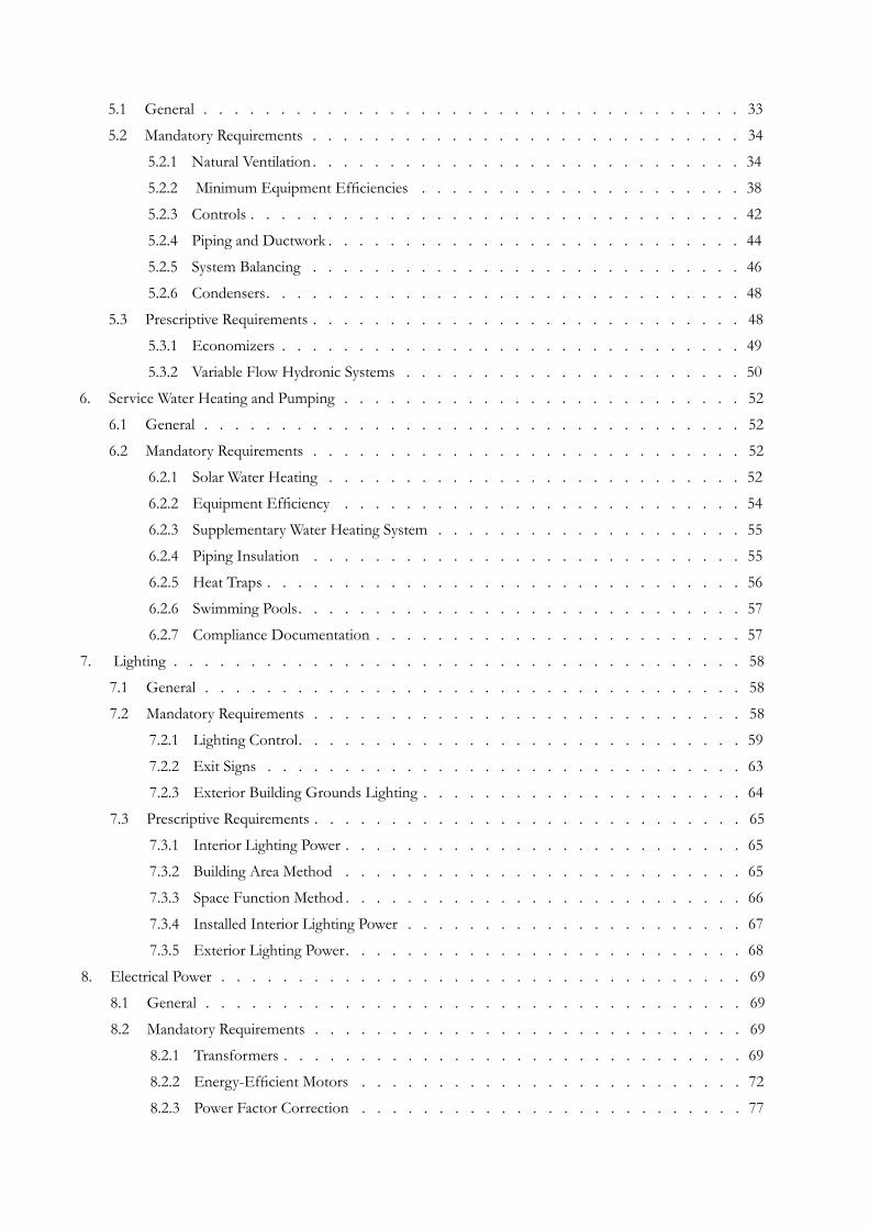
General5.1 . . . . . . . . . . . . . . . . . . . . . . . . . . . . . . . . . . . 33
Mandatory Requirements5.2 . . . . . . . . . . . . . . . . . . . . . . . . . . . . 34
Natural Ventilation5.2.1 . . . . . . . . . . . . . . . . . . . . . . . . . . . . 34
Minimum Equipment Efficiencies5.2.2 . . . . . . . . . . . . . . . . . . . . . 38
Controls5.2.3 . . . . . . . . . . . . . . . . . . . . . . . . . . . . . . . . 42
Piping and Ductwork5.2.4 . . . . . . . . . . . . . . . . . . . . . . . . . . . 44
System Balancing5.2.5 . . . . . . . . . . . . . . . . . . . . . . . . . . . . 46
Condensers5.2.6 . . . . . . . . . . . . . . . . . . . . . . . . . . . . . . . 48
Prescriptive Requirements5.3 . . . . . . . . . . . . . . . . . . . . . . . . . . . . 48
Economizers5.3.1 . . . . . . . . . . . . . . . . . . . . . . . . . . . . . . 49
Variable Flow Hydronic Systems5.3.2 . . . . . . . . . . . . . . . . . . . . . . 50
Service Water Heating and Pumping6. . . . . . . . . . . . . . . . . . . . . . . . . . . 52
General6.1 . . . . . . . . . . . . . . . . . . . . . . . . . . . . . . . . . . . 52
Mandatory Requirements6.2 . . . . . . . . . . . . . . . . . . . . . . . . . . . . 52
Solar Water Heating6.2.1 . . . . . . . . . . . . . . . . . . . . . . . . . . . 52
Equipment Efficiency6.2.2 . . . . . . . . . . . . . . . . . . . . . . . . . . 54
Supplementary Water Heating System6.2.3 . . . . . . . . . . . . . . . . . . . . 55
Piping Insulation6.2.4 . . . . . . . . . . . . . . . . . . . . . . . . . . . . 55
Heat Traps6.2.5 . . . . . . . . . . . . . . . . . . . . . . . . . . . . . . . 56
Swimming Pools6.2.6 . . . . . . . . . . . . . . . . . . . . . . . . . . . . . 57
Compliance Documentation6.2.7 . . . . . . . . . . . . . . . . . . . . . . . . 57
Lighting7. . . . . . . . . . . . . . . . . . . . . . . . . . . . . . . . . . . . . . 58
General7.1 . . . . . . . . . . . . . . . . . . . . . . . . . . . . . . . . . . . 58
Mandatory Requirements7.2 . . . . . . . . . . . . . . . . . . . . . . . . . . . . 58
Lighting Control7.2.1 . . . . . . . . . . . . . . . . . . . . . . . . . . . . . 59
Exit Signs7.2.2 . . . . . . . . . . . . . . . . . . . . . . . . . . . . . . . 63
Exterior Building Grounds Lighting7.2.3 . . . . . . . . . . . . . . . . . . . . . 64
Prescriptive Requirements7.3 . . . . . . . . . . . . . . . . . . . . . . . . . . . . 65
Interior Lighting Power7.3.1 . . . . . . . . . . . . . . . . . . . . . . . . . . 65
Building Area Method7.3.2 . . . . . . . . . . . . . . . . . . . . . . . . . . 65
Space Function Method7.3.3 . . . . . . . . . . . . . . . . . . . . . . . . . . 66
Installed Interior Lighting Power7.3.4 . . . . . . . . . . . . . . . . . . . . . . 67
Exterior Lighting Power7.3.5 . . . . . . . . . . . . . . . . . . . . . . . . . . 68
Electrical Power8. . . . . . . . . . . . . . . . . . . . . . . . . . . . . . . . . . . 69
General8.1 . . . . . . . . . . . . . . . . . . . . . . . . . . . . . . . . . . . 69
Mandatory Requirements8.2 . . . . . . . . . . . . . . . . . . . . . . . . . . . . 69
Transformers8.2.1 . . . . . . . . . . . . . . . . . . . . . . . . . . . . . . 69
Energy-Efficient Motors8.2.2 . . . . . . . . . . . . . . . . . . . . . . . . . 72
Power Factor Correction8.2.3 . . . . . . . . . . . . . . . . . . . . . . . . . 77
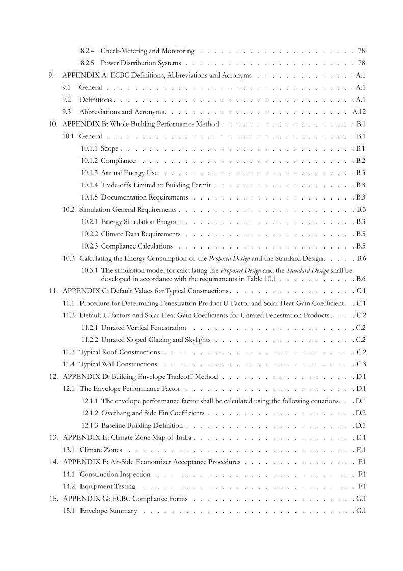
Check-Metering and Monitoring8.2.4 . . . . . . . . . . . . . . . . . . . . . . 78
Power Distribution Systems8.2.5 . . . . . . . . . . . . . . . . . . . . . . . . 78
APPENDIX A: ECBC Definitions, Abbreviations and Acronyms9. . . . . . . . . . . . . . . A.1
General9.1 . . . . . . . . . . . . . . . . . . . . . . . . . . . . . . . . . . . A.1
Definitions9.2 . . . . . . . . . . . . . . . . . . . . . . . . . . . . . . . . . . A.1
Abbreviations and Acronyms9.3 . . . . . . . . . . . . . . . . . . . . . . . . . . A.12
APPENDIX B: Whole Building Performance Method10. . . . . . . . . . . . . . . . . . . . B.1
General10.1 . . . . . . . . . . . . . . . . . . . . . . . . . . . . . . . . . . . B.1
Scope10.1.1 . . . . . . . . . . . . . . . . . . . . . . . . . . . . . . . . . B.1
Compliance 10.1.2 . . . . . . . . . . . . . . . . . . . . . . . . . . . . . . B.2
Annual Energy Use10.1.3 . . . . . . . . . . . . . . . . . . . . . . . . . . . B.3
Trade-offs Limited to Building Permit10.1.4 . . . . . . . . . . . . . . . . . . . . B.3
Documentation Requirements10.1.5 . . . . . . . . . . . . . . . . . . . . . . . B.3
Simulation General Requirements10.2 . . . . . . . . . . . . . . . . . . . . . . . . . B.3
Energy Simulation Program10.2.1 . . . . . . . . . . . . . . . . . . . . . . . . B.3
Climate Data Requirements10.2.2 . . . . . . . . . . . . . . . . . . . . . . . . B.5
Compliance Calculations10.2.3 . . . . . . . . . . . . . . . . . . . . . . . . . B.5
Calculating the Energy Consumption of the 10.3 Proposed Design and the Standard Design . . . . . B.6
The simulation model for calculating the 10.3.1 Proposed Design and the Standard Design shall be developed in accordance with the requirements in Table 10.1 . . . . . . . . . . . B.6
APPENDIX C: Default Values for Typical Constructions11. . . . . . . . . . . . . . . . . . . C.1
Procedure for Determining Fenestration Product U-Factor and Solar Heat Gain Coefficient11.1 . . C.1
Default U-factors and Solar Heat Gain Coefficients for Unrated Fenestration Products11.2 . . . . C.2
Unrated Vertical Fenestration 11.2.1 . . . . . . . . . . . . . . . . . . . . . . . C.2
Unrated Sloped Glazing and Skylights11.2.2 . . . . . . . . . . . . . . . . . . . . C.2
Typical Roof Constructions11.3 . . . . . . . . . . . . . . . . . . . . . . . . . . . C.2
Typical Wall Constructions11.4 . . . . . . . . . . . . . . . . . . . . . . . . . . . . C.3
APPENDIX D: Building Envelope Tradeoff Method12. . . . . . . . . . . . . . . . . . . . D.1
The Envelope Performance Factor 12.1 . . . . . . . . . . . . . . . . . . . . . . . . D.1
The envelope performance factor shall be calculated using the following equations. 12.1.1 . . D.1
Overhang and Side Fin Coefficients12.1.2 . . . . . . . . . . . . . . . . . . . . . D.2
Baseline Building Definition12.1.3 . . . . . . . . . . . . . . . . . . . . . . . . D.5
APPENDIX E: Climate Zone Map of India13. . . . . . . . . . . . . . . . . . . . . . . . E.1
Climate Zones13.1 . . . . . . . . . . . . . . . . . . . . . . . . . . . . . . . . E.1
APPENDIX F: Air-Side Economizer Acceptance Procedures14. . . . . . . . . . . . . . . . . F.1
Construction Inspection14.1 . . . . . . . . . . . . . . . . . . . . . . . . . . . . F.1
Equipment Testing14.2 . . . . . . . . . . . . . . . . . . . . . . . . . . . . . . . F.1
APPENDIX G: ECBC Compliance Forms15. . . . . . . . . . . . . . . . . . . . . . . . G.1
Envelope Summary15.1 . . . . . . . . . . . . . . . . . . . . . . . . . . . . . . G.1
Building Permit Plans Checklist15.2 . . . . . . . . . . . . . . . . . . . . . . . . . . G.2
Mechanical Summary15.3 . . . . . . . . . . . . . . . . . . . . . . . . . . . . . . G.3
Mechanical Permit Checklist15.4 . . . . . . . . . . . . . . . . . . . . . . . . . . . G.4
Lighting Summary15.5 . . . . . . . . . . . . . . . . . . . . . . . . . . . . . . . G.5
Lighting Permit Checklist15.6 . . . . . . . . . . . . . . . . . . . . . . . . . . . . G.6
Whole Building Performance Checklist15.7 . . . . . . . . . . . . . . . . . . . . . . . G.7
APPENDIX H: Comparison Of International Building Energy Standards16. . . . . . . . . . . . H.1
APPENDIX I: References17. . . . . . . . . . . . . . . . . . . . . . . . . . . . . . . I.1
List of TablesTable 4.1: Values of Surface Film Resistance Based on Direction of Heat Flow . . . . . . . . . . . 14
Table 4.2: Thermal Resistances of Unventilated Air Layers Between Surfaces with High Emittance . . . 15
Table 4.3: Comfort Requirements and Physical Manifestations in Buildings . . . . . . . . . . . . . 19
Table 4.4: Roof Assembly U-Factor and Insulation R-value Requirements (ECBC Table 4.3.1) . . . . . 21
Table 4.5: Opaque Wall Assembly U-Factor and Insulation R-value Requirements (ECBC Table 4.2) . . . 26
Table 4.6: Vertical Fenestration U-factor (W/m2·K) and SHGC Requirements (ECBC Table 4.3) . . . . 26
Table 4.7: Defaults for Unrated Vertical Fenestration (Overall Assembly including Sash and Frame) - Table 11.1 of ECBC . . . . . . . . . . . . . . . . . . . . . . . . . . . . . . . 27
Table 4.8: SHGC “M” Factor Adjustments for Overhangs and Fins (ECBC Table 4.4) . . . . . . . . 28
Table 4.9: Minimum VLT Requirements (ECBC Table 4.5) . . . . . . . . . . . . . . . . . . . 29
Table 4.10: Skylight U-Factor and SHGC Requirements (ECBC Table 4.6) . . . . . . . . . . . . . 31
Table 5.1: Optimum Size/Number of Fans for Rooms of Different Sizes . . . . . . . . . . . . . 37
Table 5.2: Chillers. . . . . . . . . . . . . . . . . . . . . . . . . . . . . . . . . . . . 41
Table 5.3: Power Consumption Ratings for Unitary Air Conditioners – Under Test Conditions . . . . . 42
Table 5.4: Power Consumption Ratings for Split Air Conditioners – Under Test Conditions . . . . . . 42
Table 5.5: Power Consumption Rating for Packaged air Conditioners-under test conditions . . . . . . 42
Table 5.6: Insulation of Heating Systems . . . . . . . . . . . . . . . . . . . . . . . . . . 44
Table 5.7: Insulation of Cooling Systems . . . . . . . . . . . . . . . . . . . . . . . . . . 44
Table 5.8: Ductwork Insulation . . . . . . . . . . . . . . . . . . . . . . . . . . . . . . 45
Table 5.9: Sample R-values for Duct Insulation Materials . . . . . . . . . . . . . . . . . . . . 45
Table 6.1: Standing Loss in Storage Type Electric Water Heaters . . . . . . . . . . . . . . . . . 55
Table 6.2: Insulation of Hot Water Piping. . . . . . . . . . . . . . . . . . . . . . . . . . . 55
Table 7.1: Interior Lighting Power- Building Area Method (ECBC Table 7.1) . . . . . . . . . . . . 66
Table 7.2: Interior Lighting Power- Space Function Method (ECBC Table 7.2) . . . . . . . . . . . . 66
Table 7.3: Exterior Lighting Building Power (ECBC Table 7.3) . . . . . . . . . . . . . . . . . . 68
Table 8.1: Dry-Type Transformers (ECBC Table 8.1) . . . . . . . . . . . . . . . . . . . . . . 71
Table 8.2: Oil Filled Transformers (ECBC Table 8.2) . . . . . . . . . . . . . . . . . . . . . . 71
Table 8.3: Values of Performance Characteristic of Two Pole Energy-Efficient Induction Motors. . . . . 73
Table 8.4: Values of Performance Characteristic of 4 Pole Energy-Efficient Induction Motors. . . . . . 74
Table 8.5: Values of Performance Characteristic of 6 Pole Energy-Efficient Induction Motors. . . . . . 75
Table 8.6: Values of Performance Characteristic of 8 Pole Energy-Efficient Induction Motors. . . . . . 75
Table 10.1: Modeling Requirements for Calculating Proposed and Standard Design . . . . . . . . . . B.7
Table 10.2: Standard Fan Brake Horsepower . . . . . . . . . . . . . . . . . . . . . . . . B.19
Table 10.3: Type and Number of Chillers . . . . . . . . . . . . . . . . . . . . . . . . . B.19
Table 10.4: Part-Load Performance for VAV Fan Systems . . . . . . . . . . . . . . . . . . . B.20
Table 10.5: HVAC Systems Map (Reproduced from ECBC 10.2) . . . . . . . . . . . . . . . . B.22
Table 10.6: Electrically Operated Packaged Terminal Air Conditioners . . . . . . . . . . . . . . B.22
Table 10.7: Building Energy Model Information. . . . . . . . . . . . . . . . . . . . . . . B.23
Table 11.1: Defaults for Unrated Vertical Fenestration (Overall Assembly including the Sash and Frame) . C.2
Table 11.2: Defaults for effective U-Factor for Exterior Insulation layers (under review) . . . . . . . . C.2
Table 11.3: Defaults for effective U-factor for Exterior Insulation Layers (under review) . . . . . . . . C.3
Table 12.1: Envelope Performance Factor Coefficients-Composite Climate (under review) . . . . . . . D.1
Table 12.2: Envelope Performance Factor Coefficients-Hot Dry Climate (under review) . . . . . . . . D.2
Table 12.3: Envelope Performance Factor Coefficients-Hot Humid Climate (under review) . . . . . . D.2
Table 12.4: Envelope Performance Factor Coefficients-Moderate Climate (under review) . . . . . . . D.2
Table 12.5: Envelope Performance Factor Coefficients-Cold Climate (under review) . . . . . . . . . D.2
Table 12.6: Overhang and Side Fin Coefficients . . . . . . . . . . . . . . . . . . . . . . . . D.3
Table 13.1: Classifications of Different Climate Zones in India . . . . . . . . . . . . . . . . . . E.2
Table 13.2: Climate Zone of the Major Indian Cities . . . . . . . . . . . . . . . . . . . . . . E.3
List of FiguresFigure 3.1: Design Process for the Whole Building Performance Method . . . . . . . . . . . . . . 7
Figure 3.2: The Building Design and Construction Process . . . . . . . . . . . . . . . . . . . 9
Figure 4.1: Building Envelope . . . . . . . . . . . . . . . . . . . . . . . . . . . . . . . 12
Figure 4.2: The Solar and Blackbody Spectrum . . . . . . . . . . . . . . . . . . . . . . . . 13
Figure 4.3: Schematic Showing Three Modes of Heat Transfer . . . . . . . . . . . . . . . . . . 13
Figure 4.4: Typical Cavity Wall Construction . . . . . . . . . . . . . . . . . . . . . . . . . 15
Figure 4.5: Direct and Indirect Solar Radiation . . . . . . . . . . . . . . . . . . . . . . . . 16
Figure 4.6: Heat Transfer (Conduction, Convection, & Radiation) and Infiltration Across a Window . . . . 17
Figure 4.7: Building Roofs . . . . . . . . . . . . . . . . . . . . . . . . . . . . . . . . 23
Figure 4.8: Typical Insulation Techniques for RCC Roof Construction. . . . . . . . . . . . . . . 24
Figure 4.9: Heat Transfer Through Roof . . . . . . . . . . . . . . . . . . . . . . . . . . 24
Figure 4.10: Projection Calculation . . . . . . . . . . . . . . . . . . . . . . . . . . . . . 28
Figure 4.11: Illustration to show U-factor, SHGC, and VLT . . . . . . . . . . . . . . . . . . . 30
Figure 4.12: Skylight Installations . . . . . . . . . . . . . . . . . . . . . . . . . . . . . 31
Figure 5.1: Acceptable operative temperature ranges for naturally conditioned spaces. . . . . . . . . . 38
Figure 5.2: Economizer . . . . . . . . . . . . . . . . . . . . . . . . . . . . . . . . . 49
Figure 6.1: Batch Collector Passive System . . . . . . . . . . . . . . . . . . . . . . . . . . 53
Figure 6.2: Active Indirect System . . . . . . . . . . . . . . . . . . . . . . . . . . . . . 53
Figure 6.3: Instantaneous Water Heater . . . . . . . . . . . . . . . . . . . . . . . . . . . 54
Figure 6.4: Heat Trap Elements . . . . . . . . . . . . . . . . . . . . . . . . . . . . . . 57
Figure 7.1: Relative Efficacy of Major Light Sources (Lumens/Watt) . . . . . . . . . . . . . . . 64
Figure 7.2: Watts per Lighting System Efficiency . . . . . . . . . . . . . . . . . . . . . . . 64
Figure 8.1: Transformer . . . . . . . . . . . . . . . . . . . . . . . . . . . . . . . . . 69
Figure 8.2: Transformer loss vs % Load . . . . . . . . . . . . . . . . . . . . . . . . . . . 70
Figure 8.3: Increase in efficiency (Percentage points) . . . . . . . . . . . . . . . . . . . . . . 76
Figure 8.4: Profile cutaway of an induction motor stator and rotor . . . . . . . . . . . . . . . . 77
Figure 13.1: Climate Zone Map . . . . . . . . . . . . . . . . . . . . . . . . . . . . . . E.1

Purpose
Energy Conservation Building Code (ECBC) User Guide 1
Purpose1.
T he purpose of Energy Conservation Building Code (ECBC) is to provide minimum requirements for energy-efficient design and construction of buildings and their systems.
The building sector represents about 33% of electricity consumption in India, with commercial sector and residential sector accounting for 8%and 25% respectively. Estimates based on computer simulation models indicate that ECBC-compliant buildings can use 40 to 60% less energy than conventional buildings. It is estimated that the nationwide mandatory enforcement of the ECBC will yield annual savings of approximately 1.7 billion kWh. The ECBC is expected to overcome market barriers, which otherwise result in under-investment in building energy efficiency.
The ECBC was developed as a first step towards promoting energy efficiency in the building sector. The ECBC (also referred to as “The Code” in this document) is the result of extensive work by the Bureau of Energy Efficiency (BEE) and its Committee of Experts. It is written in code-enforceable language and addresses the views of the manufacturing, design, and construction communities as an appropriate set of minimum requirements for energy-efficient building design and construction.
For developing the Code, building construction methods across the country were reviewed and various energy-efficient design and construction practices were evaluated that could reduce energy consumption in building. In addition, detailed life-cycle cost analyses were conducted to ensure that the Code requirements reflect cost-effectiveness and practical efficiency measures across five different climate zones in India. While taking into account different climate zones, the Code also addresses site orientation and specifies better design practices and technologies that can reduce energy consumption without sacrificing comfort and productivity of the occupants.
The ECBC User Guide (also referred to as “The Guide” in this document) has been developed to provide detailed guidance to building owners, designers, engineers, builders, energy consultants, and others on how to comply with the Code. It provides expanded interpretation, examples, and supplementary information to assist in applying ECBC during the design and construction of new buildings as well as additions and alterations to existing buildings. This Guide can also be used as a document by “authorities having jurisdiction” in the enforcement of the Code once it is made mandatory. The Guide follows the nomenclature of the Code. It is written both as a reference and as an instructional guide, and can be helpful for anyone who is directly or indirectly involved in the design and construction of ECBC-compliant buildings.
Scope
Energy Conservation Building Code (ECBC) User Guide 2
Scope2.
The Code is applicable to buildings or building complexes that have a connected load of 500 kW or greater or a contract demand of 600 kVA or greater.
Generally, buildings or complexes having conditioned area of 1,000 m2 or more will fall under this category.
The Code is presently under voluntary adoption in the country.
This Code would become mandatory as and when it is notified by the Central and State government in the official Gazette under clause (p) of §14 or clause (a) of §15 of the Energy Conservation Act 2001 (52 of 2001)
Applicable Building Systems2.1 The provisions of the Code apply to:
Building envelopes, except for unconditioned storage spaces or warehouses•
Mechanical systems and equipment, including heating, ventilating, and air conditioning, (HVAC) •
Service hot water heating •
Interior and exterior lighting•
Electrical power and motors •
Specific compliance requirement of the above building components and systems are discussed in Chapter 4 through Chapter 8 of this Guide.
Exemptions2.2 The provisions of this Code do not apply to:
Buildings that do not use either electricity or fossil fuel•
Equipment and portions of building systems that use energy primarily for manufacturing processes •
Safety, Health, And Environmental Codes Take Precedence2.3 Where this Code is found to conflict with safety, health, or environmental codes, the safety, health, or environmental codes shall take precedence.
Reference Standards2.4 National Building Code (NBC) 2005 is the reference document/standard for lighting levels, HVAC, comfort levels, natural ventilation, pump and motor efficiencies, transformer efficiencies and any other building materials and system performance criteria.
The National Building Code 2005 has also been used as a reference in this Guide.
The Code is a dynamic document under continuous maintenance. Addenda, errata, and interpretations can be issued as and when necessary by the concerned authorities such as the Ministry of Power, the Bureau of Energy Efficiency, the state governments, etc. This Guide is consistent with ECBC 2007 (revised version, May 2008). Designers using this Guide should confirm if any addendum has been adopted in the Code by the Authority Having Jurisdiction before incorporating its requirements in the proposed building’s design.
Administration and Enforcement
Energy Conservation Building Code (ECBC) User Guide 3
Administration and Enforcement3. 1
This chapter addresses administration and enforcement issues, as well as general requirements for demonstrating compliance with the Code. The compliance requirements of the Code have been made flexible enough to allow
architects and engineers the ability to comply with the Code and meet the specific needs of their projects according to the climatic conditions of the site.
Compliance Requirements3.1 As mentioned in Chapter 2, all the buildings or building complexes with a connected load of 500 kW or greater or a contract demand of 600 kVA or greater have to comply with the Code. Buildings with 1,000 m2 or more of conditioned area are likely to fall under the above load conditions. The following sections which deal with mandatory and prescriptive requirements of new and existing buildings are related to this specified threshold area. It is important to mention here that these mandatory and prescriptive requirements are applicable only where the building has a connected load of 500 kW or more or contract demand of 600kVA or more.
Mandatory Requirements3.1.1 Compliance with the requirements of the Code shall be mandatory for all applicable buildings mentioned under Chapter 2 of the Code.
New Buildings3.1.2 The Code compliance procedure requires the new building to fulfill a set of mandatory provisions related to energy use as well as show compliance with the specified requirements stipulated for the different building components and systems.
The mandatory requirements are described in Sections 4.2, 5.2, 6.2, 7.2, and 8.2 of the Code. These mandatory provisions are discussed in the corresponding sections of this Guide.
The Code also specifies prescriptive requirements for building components and systems. However, to maintain flexibility for the design and construction team, the Code compliance requirements can be met by following one of two methods:
Prescriptive Method1. specifies prescribed minimum energy efficiency parameters for various components and systems of the proposed building. The prescriptive requirements are covered in Chapter 4 through Chapter 8 dealing with the building envelope, HVAC systems, service hot water and pumping, lighting systems, and electric power respectively. To use the building envelope section as an example, designers can choose the prescriptive method that offers flexibility in selecting insulation for roof that meets specified thermal characteristic (e.g. R-value, discussed in Chapter 4 of this Guide), in place of meeting prescriptive requirements of U-factor of the roof assembly. More explanation related to this method can be found in §3.2.
Whole Building Performance2. (WBP) is an alternative method to comply with the Code. This method is more complex than the Prescriptive Method, but offers considerable design flexibility. It allows for Code compliance to be achieved by optimizing the energy usage in various building components and systems (envelope, HVAC, lighting and other building systems) in order to find the most cost-effective solution. WBP method requires an approved computer software program to model a Proposed Design, determine its annual energy use and compare it with the Standard Design of the building. Further explanation on the WBP Method can also be found in §3.2.
1 This Chapter has been adapted from ASHRAE User Manual (2004).
Administration and Enforcement
Energy Conservation Building Code (ECBC) User Guide 4
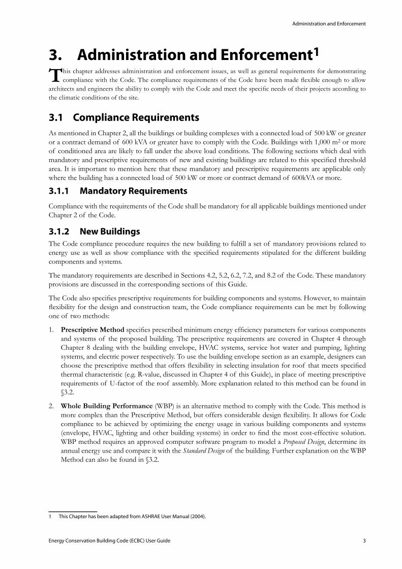
Box 3-A provides an overview of the ECBC compliance process.
: Box 3-A Steps for meeting ECBC Compliance
Additions to Existing Buildings3.1.3
Existing Building ComplianceThe Code also applies to additions in existing buildings. The requirements are triggered when new construction is proposed in the existing building.
As per the Code:
Where the addition plus the existing building exceeds the conditioned floor area of 1,000 m2 or more, the additions shall comply with the provisions of Chapter 4 through Chapter 8. Compliance may be demonstrated in either of the following ways:
The addition alone shall comply with the applicable requirements, or•
The addition, together with the entire existing • building, shall comply with the requirements of this Code that would apply to the entire building, as if it were a new building
Exception to above:
When space conditioning is provided by existing systems and equipment, the existing systems and equipment need not comply with this Code. However, any new equipment installed must comply with specific requirements applicable to that equipment.
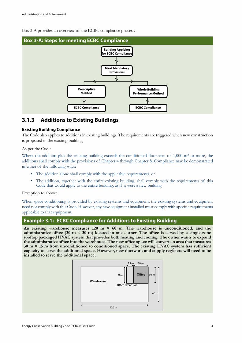
ECBC Compliance for Additions to Existing Building Example 3.1: An existing warehouse measures 120 m × 60 m. The warehouse is unconditioned, and the administrative office (30 m × 30 m) located in one corner. The office is served by a single-zone rooftop packaged HVAC system that provides both heating and cooling. The owner wants to expand the administrative office into the warehouse. The new office space will convert an area that measures 30 m × 15 m from unconditioned to conditioned space. The existing HVAC system has sufficient capacity to serve the additional space. However, new ductwork and supply registers will need to be installed to serve the additional space.
Administration and Enforcement
Energy Conservation Building Code (ECBC) User Guide 5
A: Area of Existing Office = 30m × 30m = 900m2
Additional Area of Office = 30m × 15m = 450m2
However, the Code applies to the 30m × 45m space that is being converted from unconditioned to conditioned space. The Code does not apply to the existing office or the existing warehouse space. The existing HVAC system does not need to be modified, but the ductwork extensions must be insulated to the requirements of §5. The new lighting system installed in the office addition must meet the requirements of §7. The walls that separate the office addition from the unconditioned warehouse must be insulated to the requirements of §4. The exterior wall and roof are exterior building envelope components and must meet the Code requirements.
Source: Adapted from ASHRAE User Manual (2004).
Alterations to Existing Buildings3.1.4 When making alterations to an existing building, the portions of a building and its systems that are being altered must be made to comply with mandatory and prescriptive requirements.
As per the Code:
Where the existing building exceeds the conditioned floor area threshold (of 1000 m2 or more), portions of a building and its systems that are being altered shall meet the provisions of Chapter 4 through Chapter 8 (of the Code). The specific requirements for alterations are described in the following subsections.
Exception to above:
When the entire building complies with all of the provisions of Chapter 4 through Chapter 8 (of the Code) as if it were a new building.
Building Envelope3.1.4.1
As per the Code:
Alterations to the building envelope shall comply with the requirements of Chapter 4 (of the Code) or fenestration, insulation, and air leakage applicable to the portions of the buildings and its systems being altered.
Exception to above:
The following alterations need not comply with these requirements provided such alterations do not increase the energy usage of the building:
Replacement of glass in an existing sash and frame, provided the U-factor and SHGC of the replacement • glazing are equal to or lower than the existing glazing
Modifications to roof/ceiling, wall, or floor cavities, which are insulated to full depth with insulation•
Modifications to walls and floors without cavities and where no new cavities are created•
Heating, Ventilation, and Air Conditioning3.1.4.2
As per the Code:
Alterations to building heating, ventilating, and air-conditioning equipment or systems shall comply with the requirements of Chapter 5 (of the Code) applicable to the portions of the building and its systems being altered. Any new equipment or control devices installed in conjunction with the alteration shall comply with the specific requirements applicable to that equipment or control device.
Administration and Enforcement
Energy Conservation Building Code (ECBC) User Guide 6
Service Water Heating3.1.4.3 As per the Code:
Alterations to building service water heating equipment or systems shall comply with the requirements of Chapter 6 applicable to the portions of the building and its systems being altered. Any new equipment or control devices installed in conjunction with the alteration shall comply with the specific requirements applicable to that equipment or control device.
Lighting 3.1.4.4
As per the Code:
Alterations to building lighting equipment or systems shall comply with the requirements of Chapter 7 applicable to the portions of the building and its systems being altered. New lighting systems, including controls, installed in an existing building and any change of building area type as listed in Table 7.1 shall be considered an alteration. Any new equipment or control devices installed in conjunction with the alteration shall comply with the specific requirements applicable to that equipment or control device.
Exception to above:
Alterations that replace less than 50% of the luminaires in a space need not comply with these requirements provided such alterations do not increase the connected lighting load.
Electric Power and Motors3.1.4.5
As per the Code:
Alterations to building electric power systems and motors shall comply with the requirements of Chapter 8 applicable to the portions of the building and its systems being altered. Any new equipment or control devices installed in conjunction with the alteration shall comply with the specific requirements applicable to that equipment or control device.
Compliance Approaches3.2 The Code requires that the building shall comply first with all the mandatory provisions discussed in Chapter 4 to 8 (of the Code). But every building project is different: each building has its own site that presents unique opportunities and challenges, each building owner or user has different requirements, and climate and microclimate conditions can vary significantly among projects. Architects and engineers need flexibility in order to design buildings that address these diverse requirements. The Code provides this flexibility in a number of ways. Building components and systems have multiple options to comply with the Code requirements. To use the building envelope section as an example, designers can choose the Prescriptive Method that requires roof insulation be installed with a minimum R-value. Alternatively, the other options allow the designer to show compliance with the thermal performance (U-factor) of roof construction assembly. In addition building envelope trade-off option discussed in Chapter 4 permits trade-offs among building envelope components (roof, walls, and fenestration) for Code compliance. If more flexibility is needed, the Whole Building Performance Method is available.
Prescriptive Methoda.
The Code specifies a set of prescriptive requirements for building systems and components. Compliance with the Code can be achieved by meeting or exceeding the specific levels described for each individual element of the building systems, covered in Chapter 4 through Chapter 8 of the Code. For building envelope, the Code provides a Trade-Off option that allows trading off the efficiency of one envelope element with another to achieve the overall efficiency level required by the Code. The envelope trade-off option is discussed in Chapter 12: Appendix D of ECBC.
Administration and Enforcement
Energy Conservation Building Code (ECBC) User Guide 7
Whole Building Performance Methodb.
Use of energy simulation software is necessary to show ECBC compliance via the Whole Building Performance Method. Energy simulation is a computer-based analytical process that helps building owners and designers to evaluate the energy performance of a building and make it more energy-efficient by making necessary modifications in the design before the building is constructed.
These computer-based energy simulation programs model the thermal, visual, ventilation, and other energy-consuming processes taking place within the building to predict its energy performance. The simulation program takes into account the building geometry and orientation, building materials, building façade design and characteristics, climate, indoor environmental conditions, occupant activities and schedules, HVAC and lighting system and other parameters to analyze and predict the energy performance of the building. Computer simulation of energy use can be accomplished with a variety of computer software tools and in many cases may be the best method for guiding a building project to be energy-efficient. However, this approach does require considerable knowledge of building simulation tools and very close communication between members of the design team.
Appendix B of the Code describes the Whole Building Performance Method for complying with the Code. This method involves developing a computer model of the Proposed Design and comparing its energy consumption to the Standard Design for that building. Energy consumption in the Standard Design represents the upper limit of energy use allowed for that particular building under a scenario where all the prescriptive requirements of the Code are adopted. Code compliance will be achieved if the energy use in Proposed Design is no greater than the energy used in the Standard Design. Three basic steps are involved:
Design the 1. building with energy efficiency measures; the prescriptive approach requirements provide a good starting point for the development of the design.
Demonstrate that the 2. building complies with the mandatory measures (See sections 4.2, 5.2, 6.2, 7.2, and 8.2).
Using an approved simulation software, model the energy consumption of the 3. building using the proposed features to create the Proposed Design. The model will also automatically calculate the energy use for the Proposed Design.
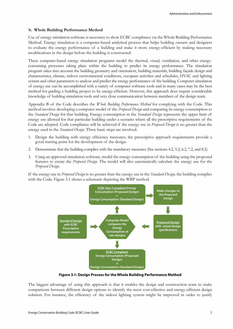
If the energy use in Proposed Design is no greater than the energy use in the Standard Design, the building complies with the Code. Figure 3.1 shows a schematic depicting the WBP method
: Design Process for the Whole Building Performance MethodFigure 3.1
The biggest advantage of using this approach is that it enables the design and construction team to make comparisons between different design options to identify the most cost-effective and energy-efficient design solution. For instance, the efficiency of the indoor lighting system might be improved in order to justify
Administration and Enforcement
Energy Conservation Building Code (ECBC) User Guide 8
fenestration design that does not meet the prescriptive envelope requirements. As long as the total energy use of the Proposed Design does not exceed the allowed energy use in Standard Design, the building will be ECBC compliant.
Note: For a detailed description of the computer simulation process and details, please refer to the ‘Energy Simulation Tip Sheet’ which can be accessed at: http://eco3.org/downloads/002-Implementationof ECBC/Energy Simulation (Public Version).pdf
Administrative Requirements3.3 As per the Code:
Administrative requirements relating to permit requirements, enforcement, interpretations, claims of exemption, approved calculation methods, and rights of appeal are specified by the Authority Having Jurisdiction.
Administration and enforcement of the Code is carried out by the local Authority Having Jurisdiction. This authority can be responsible for specifying permit requirements, code interpretations, approved calculation methods, worksheets, compliance forms, manufacturing literature, rights of appeal, and other data to demonstrate compliance. The Authority Having Jurisdiction will need to receive plans and specifications that show all pertinent data and features of the building, equipment, and systems.
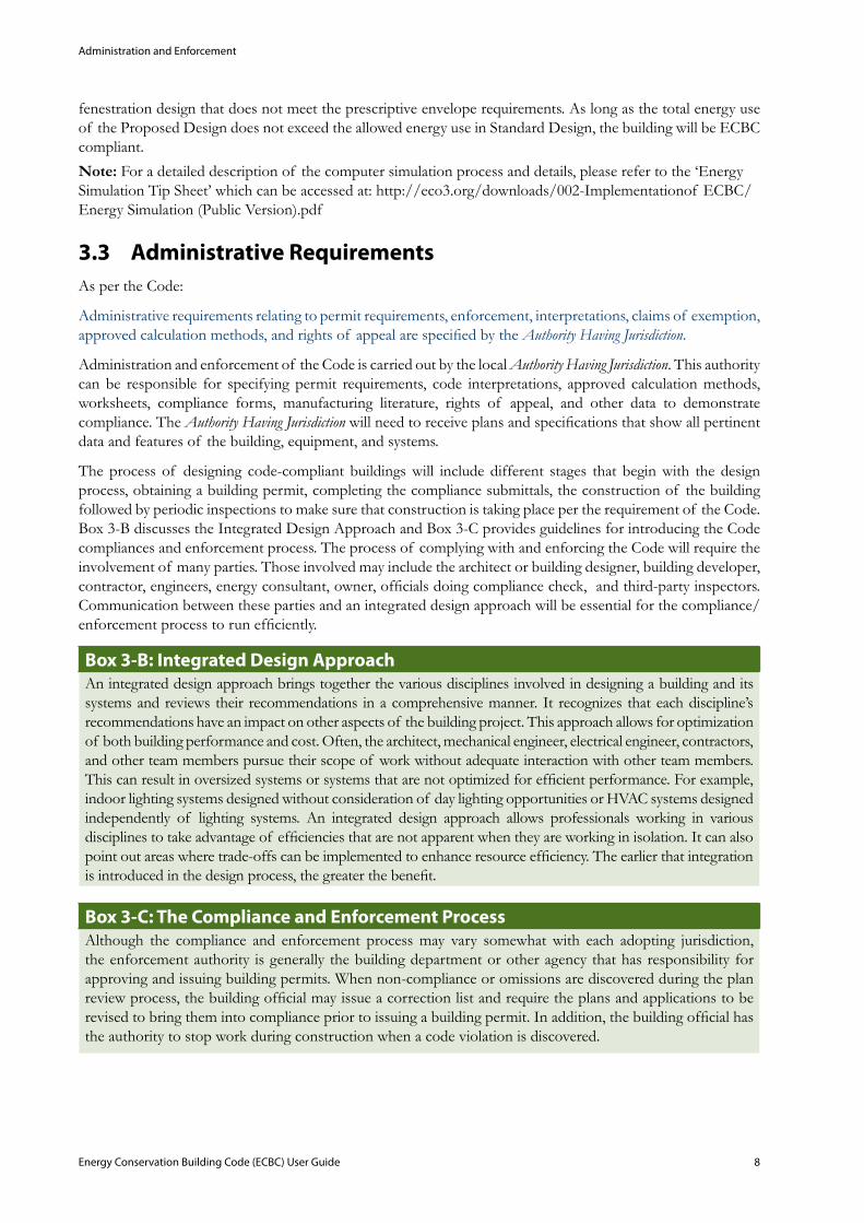
The process of designing code-compliant buildings will include different stages that begin with the design process, obtaining a building permit, completing the compliance submittals, the construction of the building followed by periodic inspections to make sure that construction is taking place per the requirement of the Code. Box 3-B discusses the Integrated Design Approach and Box 3-C provides guidelines for introducing the Code compliances and enforcement process. The process of complying with and enforcing the Code will require the involvement of many parties. Those involved may include the architect or building designer, building developer, contractor, engineers, energy consultant, owner, officials doing compliance check, and third-party inspectors. Communication between these parties and an integrated design approach will be essential for the compliance/enforcement process to run efficiently.
: Integrated Design ApproachBox 3-BAn integrated design approach brings together the various disciplines involved in designing a building and its systems and reviews their recommendations in a comprehensive manner. It recognizes that each discipline’s recommendations have an impact on other aspects of the building project. This approach allows for optimization of both building performance and cost. Often, the architect, mechanical engineer, electrical engineer, contractors, and other team members pursue their scope of work without adequate interaction with other team members. This can result in oversized systems or systems that are not optimized for efficient performance. For example, indoor lighting systems designed without consideration of day lighting opportunities or HVAC systems designed independently of lighting systems. An integrated design approach allows professionals working in various disciplines to take advantage of efficiencies that are not apparent when they are working in isolation. It can also point out areas where trade-offs can be implemented to enhance resource efficiency. The earlier that integration is introduced in the design process, the greater the benefit.
: The Compliance and Enforcement Process Box 3-CAlthough the compliance and enforcement process may vary somewhat with each adopting jurisdiction, the enforcement authority is generally the building department or other agency that has responsibility for approving and issuing building permits. When non-compliance or omissions are discovered during the plan review process, the building official may issue a correction list and require the plans and applications to be revised to bring them into compliance prior to issuing a building permit. In addition, the building official has the authority to stop work during construction when a code violation is discovered.
Administration and Enforcement
Energy Conservation Building Code (ECBC) User Guide 9
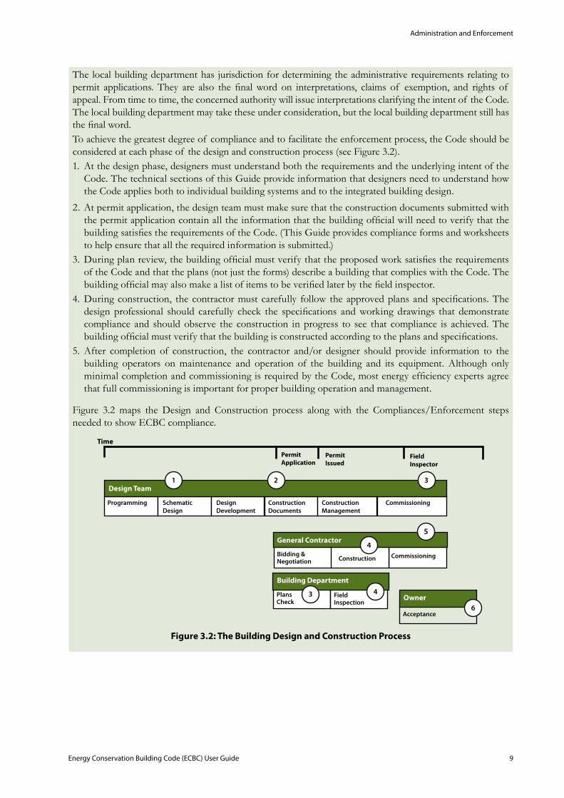
The local building department has jurisdiction for determining the administrative requirements relating to permit applications. They are also the final word on interpretations, claims of exemption, and rights of appeal. From time to time, the concerned authority will issue interpretations clarifying the intent of the Code. The local building department may take these under consideration, but the local building department still has the final word.To achieve the greatest degree of compliance and to facilitate the enforcement process, the Code should be considered at each phase of the design and construction process (see Figure 3.2).
At the design phase, designers must understand both the requirements and the underlying intent of the 1. Code. The technical sections of this Guide provide information that designers need to understand how the Code applies both to individual building systems and to the integrated building design.
At permit application, the design team must make sure that the construction documents submitted with 2. the permit application contain all the information that the building official will need to verify that the building satisfies the requirements of the Code. (This Guide provides compliance forms and worksheets to help ensure that all the required information is submitted.)During plan review, the 3. building official must verify that the proposed work satisfies the requirements of the Code and that the plans (not just the forms) describe a building that complies with the Code. The building official may also make a list of items to be verified later by the field inspector. During construction, the contractor must carefully follow the approved plans and specifications. The 4. design professional should carefully check the specifications and working drawings that demonstrate compliance and should observe the construction in progress to see that compliance is achieved. The building official must verify that the building is constructed according to the plans and specifications. After completion of construction, the contractor and/or designer should provide information to the 5. building operators on maintenance and operation of the building and its equipment. Although only minimal completion and commissioning is required by the Code, most energy efficiency experts agree that full commissioning is important for proper building operation and management.
Figure 3.2 maps the Design and Construction process along with the Compliances/Enforcement steps needed to show ECBC compliance.
: The Building Design and Construction ProcessFigure 3.2
Administration and Enforcement
Energy Conservation Building Code (ECBC) User Guide 10
Compliance Documents3.4 General3.4.1
As per the Code:
Plans and specifications shall show all pertinent data and features of the building, equipment, and systems in sufficient detail to permit the Authority Having Jurisdiction to verify that the building complies with the requirements of this code. Details shall include, but are not limited to:
Building Envelope:
Insulation materials and their R-values•
Fenestration U-factors, SHGC, visible light transmittance (if using the trade-off approach), and air • leakage
Overhang and sidefin details•
Envelope sealing details•
HVAC:
Type of systems and equipment, including their sizes, efficiencies, and controls•
Economizer details•
Variable speed drives•
Piping insulation•
Duct sealing•
Insulation type and location•
Report on HVAC balancing•
Service Hot Water and Pumping:
Solar water heating system details•
Lighting:
Schedules that show type, number, and wattage of lamps and ballasts•
Automatic lighting shutoff details•
Occupancy sensors and other lighting control details•
Lamp efficacy for exterior lamps•
Electrical Power:
Schedules that show transformer losses, motor efficiencies, and power factor correction devices•
Electric check metering and monitoring system details •
The documents submitted should include sufficient detail to allow thorough review by the Authority Having Jurisdiction for Code compliance. Additional information may be requested by the authority, if needed, to verify compliance. The compliance forms and worksheets are provided with this Guide (Appendix G) and are intended to facilitate the process of complying with the Code. These forms serve a number of functions:
They provide a permit applicant and designer the information that needs to be included on the • drawing.
They provide a structure and order for the necessary calculations. The forms allow information to be • presented in a consistent manner, which is a benefit to both the permit applicant and the enforcement agency.

Administration and Enforcement
Energy Conservation Building Code (ECBC) User Guide 11
They provide a roadmap showing the enforcement agency where to look for the necessary information • on the plans and specifications.
They provide a checklist for the enforcement agency to help structure the drawing check process.•
They promote communication between the drawings examiner and the field inspector.•
They provide a checklist for the inspector. •
Supplemental Information3.4.2 As per the Code:
The Authority Having Jurisdiction may require supplemental information necessary to verify compliance with this Code, such as calculations, worksheets, compliance forms, manufacturer’s literature, or other data.
Building Envelope
Energy Conservation Building Code (ECBC) User Guide 12
Building Envelope4. General4.1
Overview
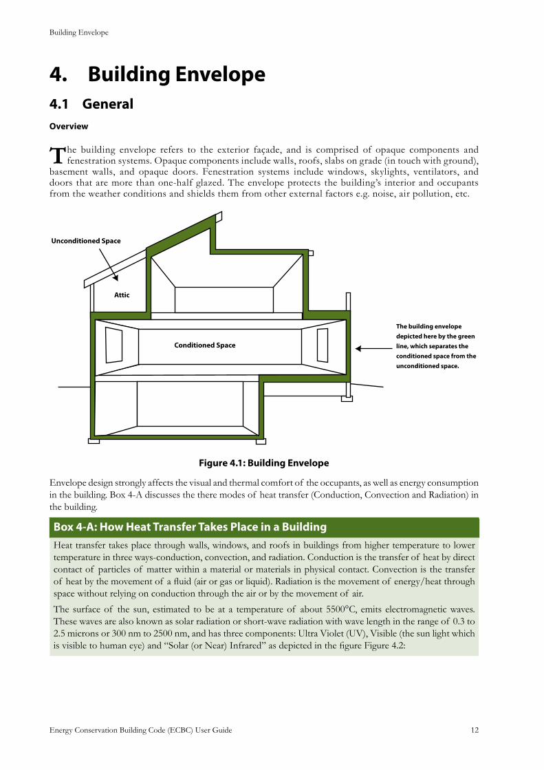
The building envelope refers to the exterior façade, and is comprised of opaque components and fenestration systems. Opaque components include walls, roofs, slabs on grade (in touch with ground),
basement walls, and opaque doors. Fenestration systems include windows, skylights, ventilators, and doors that are more than one-half glazed. The envelope protects the building’s interior and occupants from the weather conditions and shields them from other external factors e.g. noise, air pollution, etc.
The building envelope depicted here by the green line, which separates the conditioned space from the unconditioned space.
: Building EnvelopeFigure 4.1
Envelope design strongly affects the visual and thermal comfort of the occupants, as well as energy consumption in the building. Box 4-A discusses the there modes of heat transfer (Conduction, Convection and Radiation) in the building.
: How Heat Transfer Takes Place in a Building Box 4-AHeat transfer takes place through walls, windows, and roofs in buildings from higher temperature to lower temperature in three ways-conduction, convection, and radiation. Conduction is the transfer of heat by direct contact of particles of matter within a material or materials in physical contact. Convection is the transfer of heat by the movement of a fluid (air or gas or liquid). Radiation is the movement of energy/heat through space without relying on conduction through the air or by the movement of air.
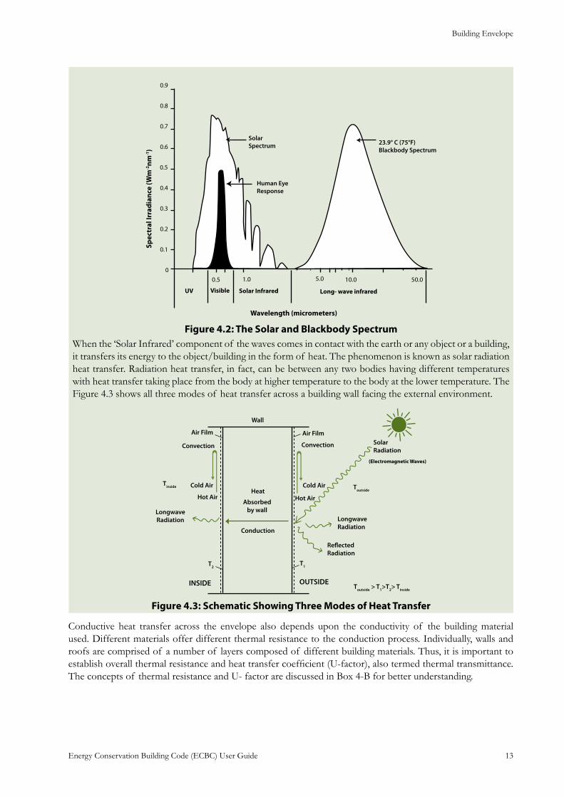
The surface of the sun, estimated to be at a temperature of about 5500°C, emits electromagnetic waves. These waves are also known as solar radiation or short-wave radiation with wave length in the range of 0.3 to 2.5 microns or 300 nm to 2500 nm, and has three components: Ultra Violet (UV), Visible (the sun light which is visible to human eye) and “Solar (or Near) Infrared” as depicted in the figure Figure 4.2:
Building Envelope
Energy Conservation Building Code (ECBC) User Guide 13
Figure 4.2: The Solar and Blackbody SpectrumWhen the ‘Solar Infrared’ component of the waves comes in contact with the earth or any object or a building, it transfers its energy to the object/building in the form of heat. The phenomenon is known as solar radiation heat transfer. Radiation heat transfer, in fact, can be between any two bodies having different temperatures with heat transfer taking place from the body at higher temperature to the body at the lower temperature. The Figure 4.3 shows all three modes of heat transfer across a building wall facing the external environment.
Figure 4.3: Schematic Showing Three Modes of Heat Transfer
Conductive heat transfer across the envelope also depends upon the conductivity of the building material used. Different materials offer different thermal resistance to the conduction process. Individually, walls and roofs are comprised of a number of layers composed of different building materials. Thus, it is important to establish overall thermal resistance and heat transfer coefficient (U-factor), also termed thermal transmittance. The concepts of thermal resistance and U- factor are discussed in Box 4-B for better understanding.
Building Envelope
Energy Conservation Building Code (ECBC) User Guide 14
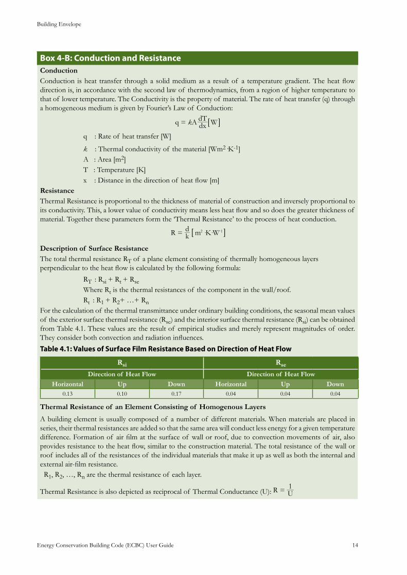
Box 4-B: Conduction and ResistanceConduction Conduction is heat transfer through a solid medium as a result of a temperature gradient. The heat flow direction is, in accordance with the second law of thermodynamics, from a region of higher temperature to that of lower temperature. The Conductivity is the property of material. The rate of heat transfer (q) through a homogeneous medium is given by Fourier’s Law of Conduction:
q A dxdT Wk= 6 @
q : Rate of heat transfer [W]
k : Thermal conductivity of the material [Wm2·K-1] A : Area [m2] T : Temperature [K] x : Distance in the direction of heat flow [m]ResistanceThermal Resistance is proportional to the thickness of material of construction and inversely proportional to its conductivity. This, a lower value of conductivity means less heat flow and so does the greater thickness of material. Together these parameters form the ‘Thermal Resistance’ to the process of heat conduction.
kd m K WR 2 1= -6 @· ·
Description of Surface ResistanceThe total thermal resistance RT of a plane element consisting of thermally homogeneous layers perpendicular to the heat flow is calculated by the following formula:
RT : Rsi
+ Rt + Rse
Where Rt is the thermal resistances of the component in the wall/roof. Rt : R1
+ R2+ …+ RnFor the calculation of the thermal transmittance under ordinary building conditions, the seasonal mean values of the exterior surface thermal resistance (Rse) and the interior surface thermal resistance (Rsi) can be obtained from Table 4.1. These values are the result of empirical studies and merely represent magnitudes of order. They consider both convection and radiation influences.
: Values of Surface Film Resistance Based on Direction of Heat FlowTable 4.1
Rsi Rse
Direction of Heat Flow Direction of Heat Flow
Horizontal Up Down Horizontal Up Down0.13 0.10 0.17 0.04 0.04 0.04
Thermal Resistance of an Element Consisting of Homogenous Layers
A building element is usually composed of a number of different materials. When materials are placed in series, their thermal resistances are added so that the same area will conduct less energy for a given temperature difference. Formation of air film at the surface of wall or roof, due to convection movements of air, also provides resistance to the heat flow, similar to the construction material. The total resistance of the wall or roof includes all of the resistances of the individual materials that make it up as well as both the internal and external air-film resistance. R1, R2, …, Rn are the thermal resistance of each layer.
Thermal Resistance is also depicted as reciprocal of Thermal Conductance (U): UR 1=
Building Envelope
Energy Conservation Building Code (ECBC) User Guide 15
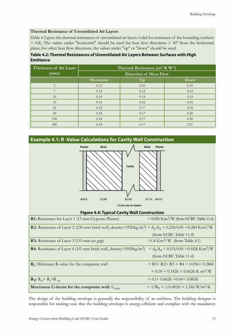
Thermal Resistance of Unventilated Air LayersTable 4.2 gives the thermal resistances of unventilated air layers (valid for emittance of the bounding surfaces > 0.8). The values under "horizontal" should be used for heat flow directions ± 30° from the horizontal plane; for other heat flow directions, the values under "up" or "down" should be used.
Table 4.2: Thermal Resistances of Unventilated Air Layers Between Surfaces with High Emittance
Thickness of Air Layer (mm)
Thermal Resistance (m2·K·W-1)Direction of Heat Flow
Horizontal Up Down5 0.12 0.10 0.10
7 0.12 0.12 0.12
10 0.14 0.14 0.14
15 0.16 0.16 0.16
25 0.18 0.17 0.18
50 0.18 0.17 0.20
100 0.18 0.17 0.20
300 0.18 0.17 0.21
: R -Value Calculations for Cavity Wall ConstructionExample 4.1
: Typical Cavity Wall Construction Figure 4.4R1: Resistance for Layer 1 (13 mm Gypsum Plaster) = 0.056 K·m2/W (from ECBC Table 11.4)
R2: Resistance of Layer 2 (230 mm brick wall, density=1920kg/m3) = d2/k2 = 0.230/0.81 =0.284 K·m2/W
(from ECBC Table 11.4)R3: Resistance of Layer 3 (115 mm air gap) =1.8 Km2/W (from Table 4.1)
R4: Resistance of Layer 4 (115 mm brick wall, density=1920kg/m3) = d4/k4 = 0.115/0.81 =0.1426 K·m2/W
(from ECBC Table 11.4)
Rt: Minimum R-value for the composite wall = R1+ R2+ R3 + R4 = 0.056+ 0.2840
+ 0.18 + 0.1426 = 0.6626 K·m2/W
RT: Rsi+ Rt+R se = 0.1+ 0.6626 +0.04= 0.8026
Maximum U-factor for the composite wall: Umin = 1/RT = 1/0.8026 = 1.246 W/m2·K
The design of the building envelope is generally the responsibility of an architect. The building designer is responsible for making sure that the building envelope is energy-efficient and complies with the mandatory
Building Envelope
Energy Conservation Building Code (ECBC) User Guide 16
and prescriptive requirements of the Code. It also provides ‘trade-off options’ which allows flexibility to the designer to ‘trade-off ’ prescriptive requirements of building components, while meeting the minimum energy performance requirements of the envelope.
Mandatory Requirements4.2 Fenestration 4.2.1
Heat transfer across glazing products or fenestration (windows, door, and skylights) is similar to the heat transfer that takes place across walls and roofs through conduction and convection. So, U-factor of glazing is analogous to the U-factor of wall assembly. In addition, direct solar radiation contributes to the solar heat gain through the fenestration system. Box 4-C discusses the concept of Solar Heat Gain Coefficient (SHGC).
Fenestration and doors must be rated using procedures and methods specified in the ECBC. Three fenestration performance characteristics are significant in the ECBC: U-factor, SHGC, and Visible Light Transmittance (VLT). These are reviewed below:
The U-factor of fenestration is very important to the energy efficiency of buildings, especially in cold climates. The U-factor must account for the entire fenestration product, including the effects of the frame, the spacers in double glazed assemblies, and the glazing. There are a wide variety of materials, systems, and techniques used to manufacture fenestration products, and accurately accounting for these factors is of utmost importance when calculating the U-factor.
According to ECBC, Fenestration U-factors must be determined in accordance with ISO-15099.
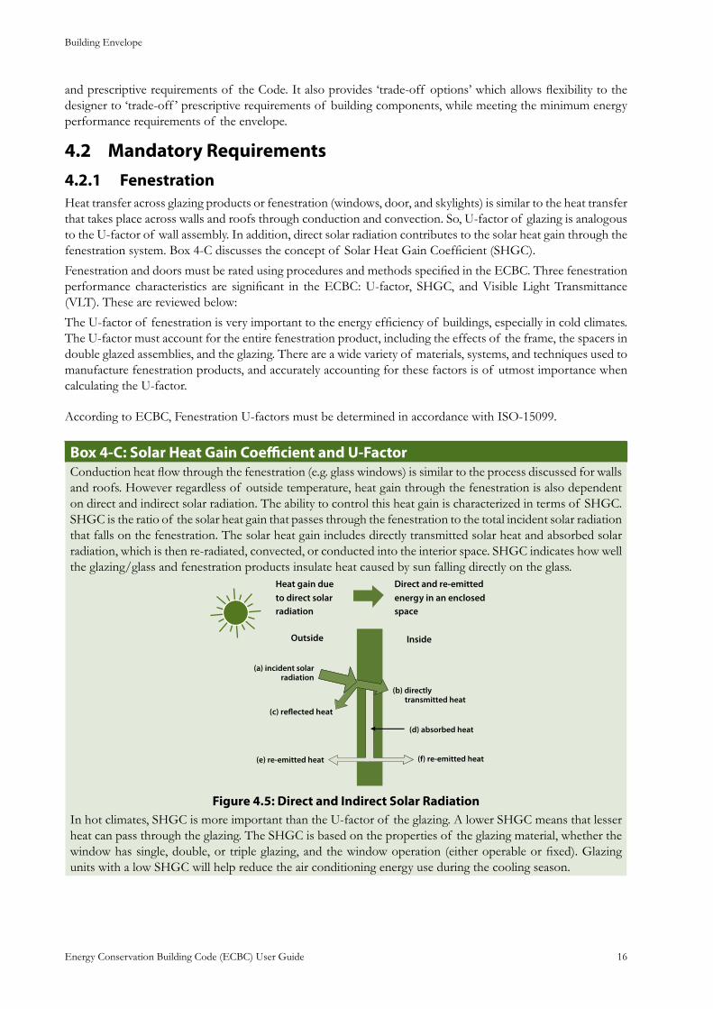
: Solar Heat Gain Coefficient and U-FactorBox 4-CConduction heat flow through the fenestration (e.g. glass windows) is similar to the process discussed for walls and roofs. However regardless of outside temperature, heat gain through the fenestration is also dependent on direct and indirect solar radiation. The ability to control this heat gain is characterized in terms of SHGC. SHGC is the ratio of the solar heat gain that passes through the fenestration to the total incident solar radiation that falls on the fenestration. The solar heat gain includes directly transmitted solar heat and absorbed solar radiation, which is then re-radiated, convected, or conducted into the interior space. SHGC indicates how well the glazing/glass and fenestration products insulate heat caused by sun falling directly on the glass.
: Direct and Indirect Solar RadiationFigure 4.5In hot climates, SHGC is more important than the U-factor of the glazing. A lower SHGC means that lesser heat can pass through the glazing. The SHGC is based on the properties of the glazing material, whether the window has single, double, or triple glazing, and the window operation (either operable or fixed). Glazing units with a low SHGC will help reduce the air conditioning energy use during the cooling season.
Building Envelope
Energy Conservation Building Code (ECBC) User Guide 17
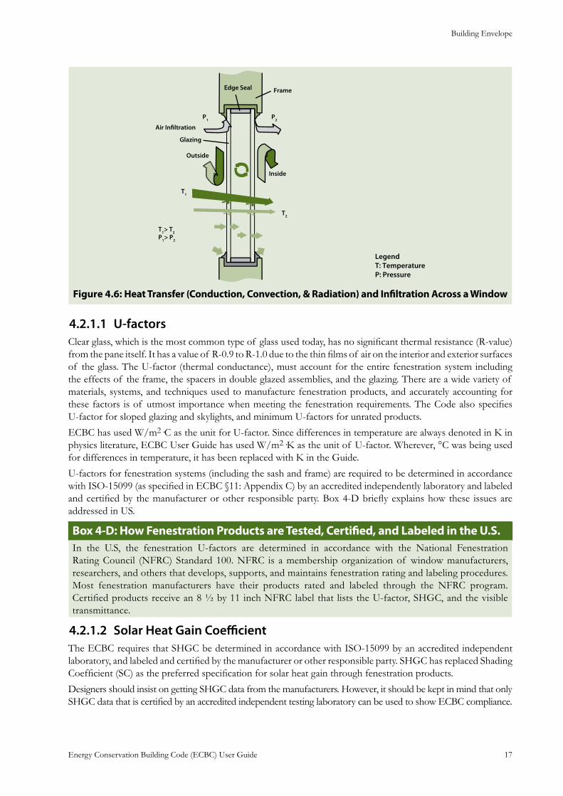
: Heat Transfer (Conduction, Convection, & Radiation) and Infiltration Across a WindowFigure 4.6
U-factors4.2.1.1 Clear glass, which is the most common type of glass used today, has no significant thermal resistance (R-value) from the pane itself. It has a value of R-0.9 to R-1.0 due to the thin films of air on the interior and exterior surfaces of the glass. The U-factor (thermal conductance), must account for the entire fenestration system including the effects of the frame, the spacers in double glazed assemblies, and the glazing. There are a wide variety of materials, systems, and techniques used to manufacture fenestration products, and accurately accounting for these factors is of utmost importance when meeting the fenestration requirements. The Code also specifies U-factor for sloped glazing and skylights, and minimum U-factors for unrated products.
ECBC has used W/m2·C as the unit for U-factor. Since differences in temperature are always denoted in K in physics literature, ECBC User Guide has used W/m2·K as the unit of U-factor. Wherever, °C was being used for differences in temperature, it has been replaced with K in the Guide.
U-factors for fenestration systems (including the sash and frame) are required to be determined in accordance with ISO-15099 (as specified in ECBC §11: Appendix C) by an accredited independently laboratory and labeled and certified by the manufacturer or other responsible party. Box 4-D briefly explains how these issues are addressed in US.
Box 4-D: How Fenestration Products are Tested, Certified, and Labeled in the U.S.In the U.S, the fenestration U-factors are determined in accordance with the National Fenestration Rating Council (NFRC) Standard 100. NFRC is a membership organization of window manufacturers, researchers, and others that develops, supports, and maintains fenestration rating and labeling procedures. Most fenestration manufacturers have their products rated and labeled through the NFRC program. Certified products receive an 8 ½ by 11 inch NFRC label that lists the U-factor, SHGC, and the visible transmittance.
Solar Heat Gain Coefficient4.2.1.2 The ECBC requires that SHGC be determined in accordance with ISO-15099 by an accredited independent laboratory, and labeled and certified by the manufacturer or other responsible party. SHGC has replaced Shading Coefficient (SC) as the preferred specification for solar heat gain through fenestration products.
Designers should insist on getting SHGC data from the manufacturers. However, it should be kept in mind that only SHGC data that is certified by an accredited independent testing laboratory can be used to show ECBC compliance.
Building Envelope
Energy Conservation Building Code (ECBC) User Guide 18
Air Leakage 4.2.1.3 Air leakage for glazed swinging entrance doors and revolving doors shall not exceed 5.0 l/s·m2. Air leakage for other fenestration and doors shall not exceed 2.0 l/s·m2.
The first set of air leakage requirements deals with inadvertent leaks at joints in the building envelope. In particular, the standard states that exterior joints, cracks, and holes in the building envelope shall be caulked, gasketed, weather stripped, or otherwise sealed. The construction drawings should specify sealing, but special attention is needed in the construction administration phase to assur e proper workmanship. A tightly constructed building envelope is largely achieved through careful construction practices and attention to detail. Poorly sealed buildings can cause problems for maintaining comfort conditions when additional infiltration loads exceed the HVAC design assumptions. This can be a significant problem in high-rise buildings due to stack effect and exposure to stronger winds.
Opaque Construction4.2.2 U-factors shall be determined from the default tables in Appendix C §11 or determined from data or procedures contained in the ASHRAE Fundamentals, 2005.
Building Envelope Sealing4.2.3 Air leakage can also occur through opaque construction. Apart from adding cooling or heating load in the building, air leakage can cause condensation within walls and roof can damage insulation material and degrade other building materials. Box 4-E discusses these aspects in more detail.
It must be noted that building sealing is more important in air-conditioned buildings. In naturally ventilated buildings, the concept of building ceiling and tight envelope runs counter to conventional and traditional wisdom.
Box 4-E: Building Envelope Sealing and Air LeakageAir leakage is the passage of air through a building envelope, wall, window, joint, etc. Leakage to the interior is referred to as infiltration and leakage to the exterior is referred to as ex-filtration. Excessive air movement significantly reduces the thermal integrity and performance of the envelope and is, therefore, a major contributor to energy consumption in a building. A tightly constructed building envelope is largely achieved through careful construction practices and attention to detail. Building envelopes should be carefully designed to limit the uncontrolled entry of outdoor air into the building. Air leakage introduces sensible heat into conditioned spaces. In climates with moist outdoor conditions, it is also a major source of latent heat. Latent heat must be removed by the air-conditioning system at considerable expense.In addition to causing energy loss, excessive air leakage can cause condensation to form within and on walls. This can create many problems including reducing insulation R-value, permanently damaging insulation, and seriously degrading materials. It can rot wood, corrode metals, stain brick or concrete surfaces, and in extreme cases cause concrete to break, bricks to separate, mortar to crumble and sections of a wall to fall jeopardizing the safety of occupants. It can corrode structural steel, re-bar, and metal hangars and bolts with very serious safety and maintenance consequences. Moisture accumulation in building materials can lead to the formation of mold that may require extensive remedying the situation. Virtually anywhere in the building envelope where there is a joint, junction or opening, there is potential for air leakage. Air leakage will cause the HVAC system to run more often and longer at one time, and still leave the building uncomfortable for its occupants.All openings in the building envelope, including joints and other openings that are potential sources of air leakage, should be to be sealed to minimize air leakage. It means that all gaps between wall panels, around doors, and other construction joints must be well sealed. Ceiling joints, lighting fixtures, plumbing openings, doors, and windows should all be considered as potential sources of unnecessary energy loss due to air infiltration.
ECBC identifies several areas in the building envelope where attention should be paid to infiltration control. These include:
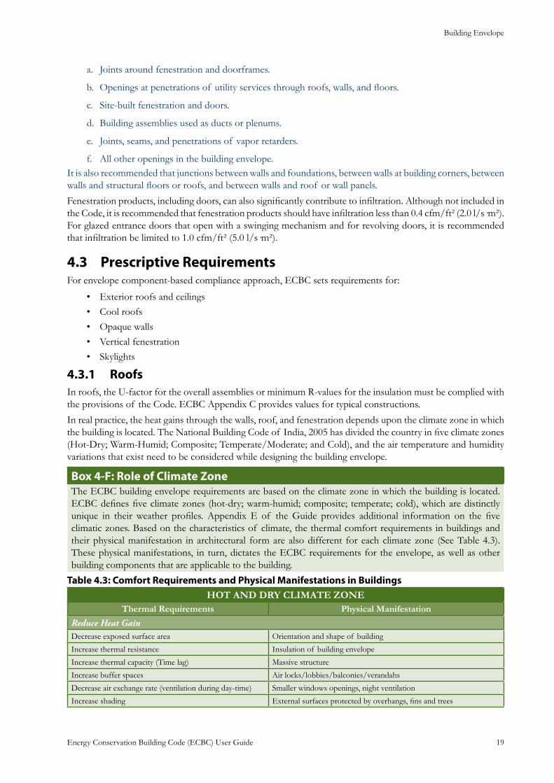
Building Envelope
Energy Conservation Building Code (ECBC) User Guide 19
Joints around fenestration and doorframes.a.
Openings at penetrations of utility services through roofs, walls, and floors.b.
Site-built fenestration and doors.c.
Building assemblies used as ducts or plenums.d.
Joints, seams, and penetrations of vapor retarders.e.
All other openings in the building envelope.f. It is also recommended that junctions between walls and foundations, between walls at building corners, between walls and structural floors or roofs, and between walls and roof or wall panels.
Fenestration products, including doors, can also significantly contribute to infiltration. Although not included in the Code, it is recommended that fenestration products should have infiltration less than 0.4 cfm/ft² (2.0 l/s·m²). For glazed entrance doors that open with a swinging mechanism and for revolving doors, it is recommended that infiltration be limited to 1.0 cfm/ft² (5.0 l/s·m²).
Prescriptive Requirements4.3 For envelope component-based compliance approach, ECBC sets requirements for:
Exterior roofs and ceilings• Cool roofs• Opaque walls• Vertical fenestration• Skylights•
Roofs4.3.1 In roofs, the U-factor for the overall assemblies or minimum R-values for the insulation must be complied with the provisions of the Code. ECBC Appendix C provides values for typical constructions.
In real practice, the heat gains through the walls, roof, and fenestration depends upon the climate zone in which the building is located. The National Building Code of India, 2005 has divided the country in five climate zones (Hot-Dry; Warm-Humid; Composite; Temperate/Moderate; and Cold), and the air temperature and humidity variations that exist need to be considered while designing the building envelope.
: Role of Climate ZoneBox 4-FThe ECBC building envelope requirements are based on the climate zone in which the building is located. ECBC defines five climate zones (hot-dry; warm-humid; composite; temperate; cold), which are distinctly unique in their weather profiles. Appendix E of the Guide provides additional information on the five climatic zones. Based on the characteristics of climate, the thermal comfort requirements in buildings and their physical manifestation in architectural form are also different for each climate zone (See Table 4.3). These physical manifestations, in turn, dictates the ECBC requirements for the envelope, as well as other building components that are applicable to the building.
Table 4.3: Comfort Requirements and Physical Manifestations in Buildings HOT AND DRY CLIMATE ZONE
Thermal Requirements Physical Manifestation
Reduce Heat Gain Decrease exposed surface area Orientation and shape of building
Increase thermal resistance Insulation of building envelope
Increase thermal capacity (Time lag) Massive structure
Increase buffer spaces Air locks/lobbies/balconies/verandahs
Decrease air exchange rate (ventilation during day-time) Smaller windows openings, night ventilation
Increase shading External surfaces protected by overhangs, fins and trees
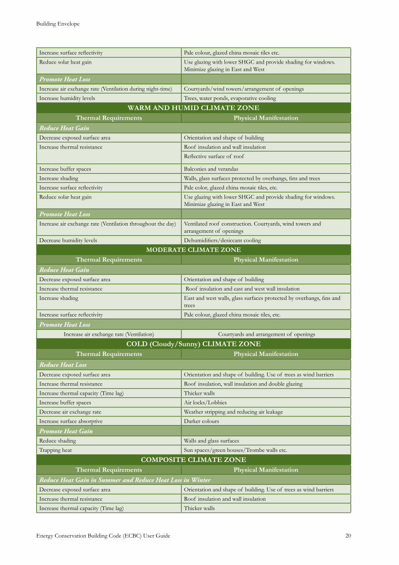
Building Envelope
Energy Conservation Building Code (ECBC) User Guide 20
Increase surface reflectivity Pale colour, glazed china mosaic tiles etc.
Reduce solar heat gain Use glazing with lower SHGC and provide shading for windows. Minimize glazing in East and West
Promote Heat Loss Increase air exchange rate (Ventilation during night-time) Courtyards/wind towers/arrangement of openings
Increase humidity levels Trees, water ponds, evaporative cooling
WARM AND HUMID CLIMATE ZONEThermal Requirements Physical Manifestation
Reduce Heat Gain Decrease exposed surface area Orientation and shape of building
Increase thermal resistance
Roof insulation and wall insulation
Reflective surface of roof
Increase buffer spaces Balconies and verandas
Increase shading Walls, glass surfaces protected by overhangs, fins and trees
Increase surface reflectivity Pale color, glazed china mosaic tiles, etc.
Reduce solar heat gain Use glazing with lower SHGC and provide shading for windows. Minimize glazing in East and West
Promote Heat Loss Increase air exchange rate (Ventilation throughout the day) Ventilated roof construction. Courtyards, wind towers and
arrangement of openings
Decrease humidity levels Dehumidifiers/desiccant cooling
MODERATE CLIMATE ZONE
Thermal Requirements Physical Manifestation
Reduce Heat Gain Decrease exposed surface area Orientation and shape of building
Increase thermal resistance Roof insulation and east and west wall insulation
Increase shading East and west walls, glass surfaces protected by overhangs, fins and trees
Increase surface reflectivity Pale colour, glazed china mosaic tiles, etc.
Promote Heat Loss Increase air exchange rate (Ventilation) Courtyards and arrangement of openings
COLD (Cloudy/Sunny) CLIMATE ZONEThermal Requirements Physical Manifestation
Reduce Heat Loss Decrease exposed surface area Orientation and shape of building. Use of trees as wind barriers
Increase thermal resistance Roof insulation, wall insulation and double glazing
Increase thermal capacity (Time lag) Thicker walls
Increase buffer spaces Air locks/Lobbies
Decrease air exchange rate Weather stripping and reducing air leakage
Increase surface absorptive Darker colours
Promote Heat GainReduce shading Walls and glass surfaces
Trapping heat Sun spaces/green houses/Trombe walls etc.
COMPOSITE CLIMATE ZONEThermal Requirements Physical Manifestation
Reduce Heat Gain in Summer and Reduce Heat Loss in WinterDecrease exposed surface area Orientation and shape of building. Use of trees as wind barriers
Increase thermal resistance Roof insulation and wall insulation
Increase thermal capacity (Time lag) Thicker walls
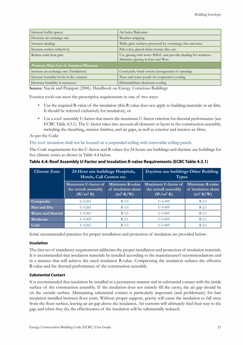
Building Envelope
Energy Conservation Building Code (ECBC) User Guide 21
Increase buffer spaces Air locks/Balconies
Decrease air exchange rate Weather stripping
Increase shading Walls, glass surfaces protected by overhangs, fins and trees
Increase surface reflectivity Pale color, glazed china mosaic tiles, etc.
Reduce solar heat gain Use glazing with lower SHGC and provide shading for windows. Minimize glazing in East and West
Promote Heat Loss in Summer/Monsoon Increase air exchange rate (Ventilation) Courtyards/wind towers/arrangement of openings
Increase humidity levels in dry summer Trees and water ponds for evaporative cooling
Decrease humidity in monsoon Dehumidifiers/desiccant cooling
Source: Nayak and Prajapati (2006). Handbook on Energy Conscious Buildings
Exterior roofs can meet the prescriptive requirements in one of two ways:
Use the required R-value of the insulation (this R-value does not apply to building materials or air film. • It should be referred exclusively for insulation), or
Use a roof assembly U-factor that meets the maximum U-factor criterion for thermal performance (see • ECBC Table 4.3.1). The U-factor takes into account all elements or layers in the construction assembly, including the sheathing, interior finishes, and air gaps, as well as exterior and interior air films.
As per the Code:
The roof insulation shall not be located on a suspended ceiling with removable ceiling panels.
The Code requirements for the U-factor and R-values for 24 hours use buildings and daytime use buildings for five climate zones as shown in Table 4.4 below.
Table 4.4: Roof Assembly U-Factor and Insulation R-value Requirements (ECBC Table 4.3.1)
Climate Zone 24-Hour use buildings Hospitals, Hotels, Call Centers etc.
Daytime use buildings Other Building Types
Maximum U-factor of the overall assembly
(W/m2·K)
Minimum R-value of insulation alone
(m2·K/W)
Maximum U-factor of the overall assembly
(W/m2·K)
Minimum R-value of insulation alone
(m2·K/W)
Composite U-0.261 R-3.5 U-0.409 R-2.1
Hot and Dry U-0.261 R-3.5 U-0.409 R-2.1
Warm and Humid U-0.261 R-3.5 U-0.409 R-2.1
Moderate U-0.409 R-2.1 U-0.409 R-2.1
Cold U-0.261 R-3.5 U-0.409 R-2.1
Some recommended practices for proper installation and protection of insulation are provided below:
Insulation
The first set of mandatory requirements addresses the proper installation and protection of insulation materials. It is recommended that insulation materials be installed according to the manufacturer’s recommendations and in a manner that will achieve the rated insulation R-value. Compressing the insulation reduces the effective R-value and the thermal performance of the construction assembly.
Substantial Contact
It is recommended that insulation be installed in a permanent manner and in substantial contact with the inside surface of the construction assembly. If the insulation does not entirely fill the cavity, the air gap should be on the outside surface. Maintaining substantial contact is particularly important (and problematic) for batt insulation installed between floor joists. Without proper support, gravity will cause the insulation to fall away from the floor surface, leaving an air gap above the insulation. Air currents will ultimately find their way to the gap, and when they do, the effectiveness of the insulation will be substantially reduced.
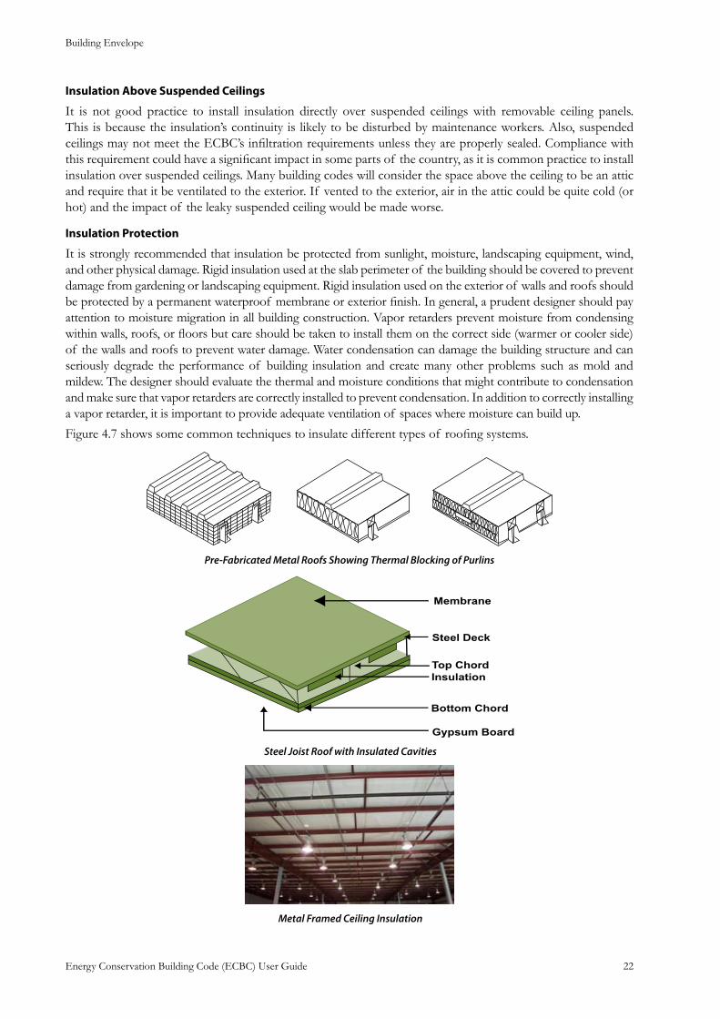
Building Envelope
Energy Conservation Building Code (ECBC) User Guide 22
Insulation Above Suspended Ceilings
It is not good practice to install insulation directly over suspended ceilings with removable ceiling panels. This is because the insulation’s continuity is likely to be disturbed by maintenance workers. Also, suspended ceilings may not meet the ECBC’s infiltration requirements unless they are properly sealed. Compliance with this requirement could have a significant impact in some parts of the country, as it is common practice to install insulation over suspended ceilings. Many building codes will consider the space above the ceiling to be an attic and require that it be ventilated to the exterior. If vented to the exterior, air in the attic could be quite cold (or hot) and the impact of the leaky suspended ceiling would be made worse.
Insulation Protection
It is strongly recommended that insulation be protected from sunlight, moisture, landscaping equipment, wind, and other physical damage. Rigid insulation used at the slab perimeter of the building should be covered to prevent damage from gardening or landscaping equipment. Rigid insulation used on the exterior of walls and roofs should be protected by a permanent waterproof membrane or exterior finish. In general, a prudent designer should pay attention to moisture migration in all building construction. Vapor retarders prevent moisture from condensing within walls, roofs, or floors but care should be taken to install them on the correct side (warmer or cooler side) of the walls and roofs to prevent water damage. Water condensation can damage the building structure and can seriously degrade the performance of building insulation and create many other problems such as mold and mildew. The designer should evaluate the thermal and moisture conditions that might contribute to condensation and make sure that vapor retarders are correctly installed to prevent condensation. In addition to correctly installing a vapor retarder, it is important to provide adequate ventilation of spaces where moisture can build up.
Figure 4.7 shows some common techniques to insulate different types of roofing systems.
Pre-Fabricated Metal Roofs Showing Thermal Blocking of Purlins
Steel Joist Roof with Insulated Cavities
Metal Framed Ceiling Insulation
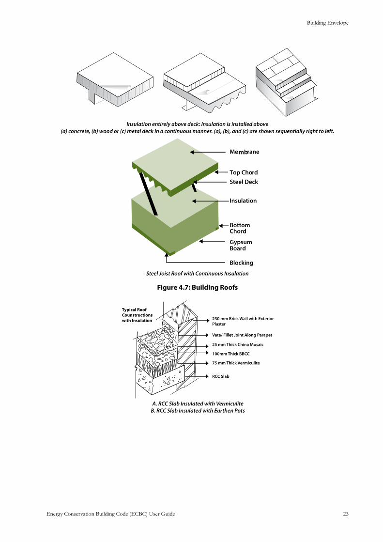
Building Envelope
Energy Conservation Building Code (ECBC) User Guide 23
Insulation entirely above deck: Insulation is installed above(a) concrete, (b) wood or (c) metal deck in a continuous manner. (a), (b), and (c) are shown sequentially right to left.
Steel Joist Roof with Continuous Insulation
: Building RoofsFigure 4.7
A. RCC Slab Insulated with Vermiculite B. RCC Slab Insulated with Earthen Pots
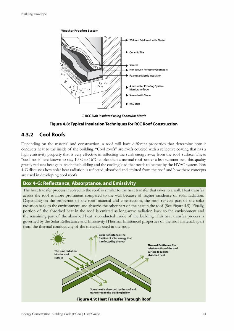
Building Envelope
Energy Conservation Building Code (ECBC) User Guide 24
C. RCC Slab Insulated using Foamular Metric
: Typical Insulation Techniques for RCC Roof ConstructionFigure 4.8
Cool Roofs4.3.2
Depending on the material and construction, a roof will have different properties that determine how it conducts heat to the inside of the building. “Cool roofs” are roofs covered with a reflective coating that has a high emissivity property that is very effective in reflecting the sun’s energy away from the roof surface. These “cool roofs” are known to stay 10°C to 16°C cooler than a normal roof under a hot summer sun; this quality greatly reduces heat gain inside the building and the cooling load that needs to be met by the HVAC system. Box 4-G discusses how solar heat radiation is reflected, absorbed and emitted from the roof and how these concepts are used in developing cool roofs.
Box 4-G: Reflectance, Absorptance, and EmissivityThe heat transfer process involved in the roof, is similar to the heat transfer that takes in a wall. Heat transfer across the roof is more prominent compared to the wall because of higher incidence of solar radiation. Depending on the properties of the roof material and construction, the roof reflects part of the solar radiation back to the environment, and absorbs the other part of the heat in the roof (See Figure 4.9). Finally, portion of the absorbed heat in the roof is emitted as long-wave radiation back to the environment and the remaining part of the absorbed heat is conducted inside of the building. This heat transfer process is governed by the Solar Reflectance and Emissivity (Thermal Emittance) properties of the roof material, apart from the thermal conductivity of the materials used in the roof.
Figure 4.9: Heat Transfer Through Roof
Building Envelope
Energy Conservation Building Code (ECBC) User Guide 25
Solar Reflectance and AbsorptanceThe solar reflectance is the fraction of solar radiation reflected by roof. The complement of reflectance is absorptance; whatever radiant energy incident on a surface that is not reflected is absorbed in the roof. The reflectance and absorptance of building materials are usually measured across the solar spectrum, since these are exposed to that range of wavelength. Reflectance is measured on a scale of 0 to 1, with 0 being a perfect absorber and 1 being a perfect reflector. Absorptance is also rated from 0 to 1, and can be calculated from the relation: Reflectance + Absorptance = 1. Emissivity or Thermal Emittance Emissivity (or thermal emittance) of a material (usually written ε or e) is the ratio of energy radiated by a particular material to energy radiated by a black body at the same temperature. It is a measure of a material’s ability to radiate the absorbed energy. A true black body would have an e =1 while any real object would have e <1. Emissivity is a dimensionless quantity (does not have units). In general, the duller and blacker a material is, the closer it’s emissivity is to 1. The more reflective a material is, the lower its emissivity. The emissivity of building material, unlike reflectance, is usually measured in the far infrared part of the spectrum.Ideal Exterior Surface An ideal exterior surface coating of a building in hot climate and under indoor cooling would have reflectance near 1, and absorptance near zero, and Emissivity near 1 to radiate absorbed heat back to the sky.
If designing a cool roof, requirements for minimum solar reflectance and initial emittance levels are specified [ECBC 4.3.1.1].
Roofs with slopes less than 20° shall have an initial solar reflectance of no less than 0.70 and an initial emittance no less than 0.75. Solar reflectance shall be determined in accordance with ASTM E903-96 and emittance shall be determined in accordance with ASTM E408-71 (RA 1996).
: Cool RoofsBox 4-HIn hot climates, cool roofs (or high emissivity or thermal emittance roof surfaces) are an effective way to reduce solar gains and cut building owners’ energy costs. Because cool roofs gain less heat than normal roofs, they reduce the need for air conditioning and make buildings more comfortable to the people inside. The light color reflects sunlight and heat away from the building, and the high emissivity or thermal emittance allows heat to escape to the atmosphere when the surface becomes heated. Although some surfaces, such as galvanized metal, have a high reflectance, they have a low emittance. These surfaces reflect heat, but heat that is absorbed cannot escape. Other surfaces, such as dark paint, have a high emittance but a low reflectance. These surfaces allow heat to escape, but do a poor job of reflecting heat that strikes the surface.Most cool roof materials for low-sloped roofs are white or another light color. For steep-sloped roofs that are often visible from the ground, roofing material manufacturers have developed popular roof colors other than white that will still reflect solar radiation or emit the sun’s energy away from the building. Cool roofs have other benefits in addition to reducing operating absorbed heat costs. For building owners, they can cut maintenance costs and increase the life expectancy of the roof. For society in general, cool roofs can even help to reduce the urban heat island effect and slow down global warming that makes our cities hotter and produces unhealthy air.
What is meant by Urban Heat Island effect?An Urban Heat Island is a metropolitan urban area, which is significantly warmer than its surroundings. As population centers grow in size, they tend to have a corresponding increase in average temperature. Scientists refer to this phenomenon as the “Urban Heat Island Effect”. The two main causes of the urban heat island is modification of the land surface by urban development and waste heat generated by energy usage. One consequence of urban heat islands is the increased energy required for air conditioning and refrigeration in cities that are in comparatively hot climates.
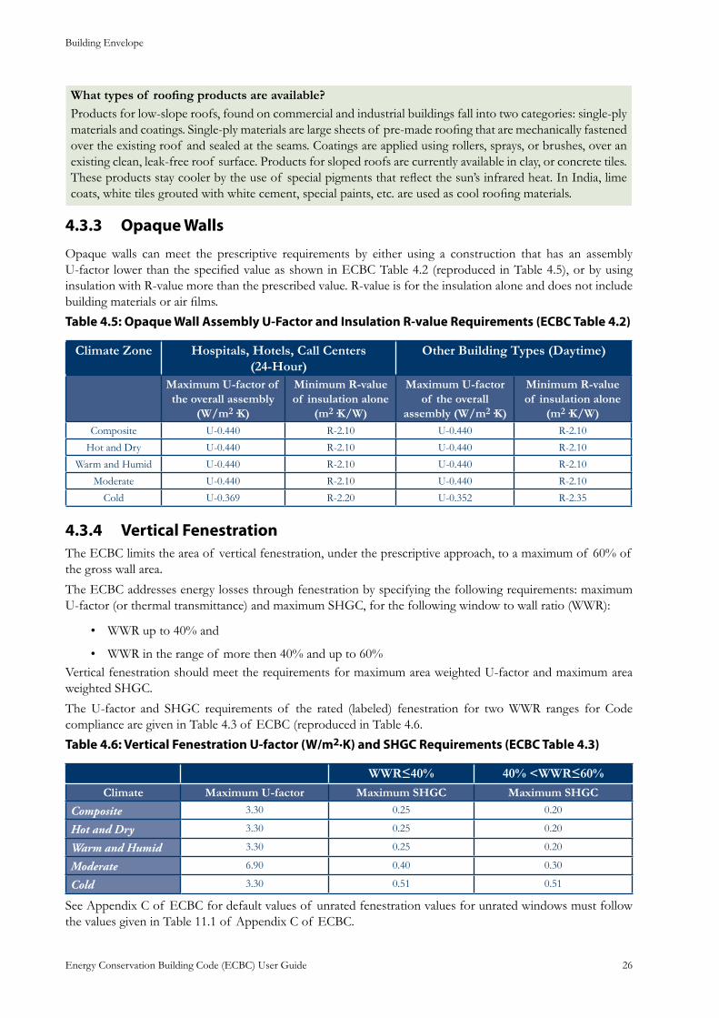
Building Envelope
Energy Conservation Building Code (ECBC) User Guide 26
What types of roofing products are available?Products for low-slope roofs, found on commercial and industrial buildings fall into two categories: single-ply materials and coatings. Single-ply materials are large sheets of pre-made roofing that are mechanically fastened over the existing roof and sealed at the seams. Coatings are applied using rollers, sprays, or brushes, over an existing clean, leak-free roof surface. Products for sloped roofs are currently available in clay, or concrete tiles. These products stay cooler by the use of special pigments that reflect the sun’s infrared heat. In India, lime coats, white tiles grouted with white cement, special paints, etc. are used as cool roofing materials.
Opaque Walls4.3.3
Opaque walls can meet the prescriptive requirements by either using a construction that has an assembly U-factor lower than the specified value as shown in ECBC Table 4.2 (reproduced in Table 4.5), or by using insulation with R-value more than the prescribed value. R-value is for the insulation alone and does not include building materials or air films.
Table 4.5: Opaque Wall Assembly U-Factor and Insulation R-value Requirements (ECBC Table 4.2)
Climate Zone Hospitals, Hotels, Call Centers (24-Hour)
Other Building Types (Daytime)
Maximum U-factor of the overall assembly
(W/m2·K)
Minimum R-value of insulation alone
(m2·K/W)
Maximum U-factor of the overall
assembly (W/m2·K)
Minimum R-value of insulation alone
(m2·K/W)Composite U-0.440 R-2.10 U-0.440 R-2.10
Hot and Dry U-0.440 R-2.10 U-0.440 R-2.10
Warm and Humid U-0.440 R-2.10 U-0.440 R-2.10
Moderate U-0.440 R-2.10 U-0.440 R-2.10
Cold U-0.369 R-2.20 U-0.352 R-2.35
Vertical Fenestration4.3.4 The ECBC limits the area of vertical fenestration, under the prescriptive approach, to a maximum of 60% of the gross wall area.
The ECBC addresses energy losses through fenestration by specifying the following requirements: maximum U-factor (or thermal transmittance) and maximum SHGC, for the following window to wall ratio (WWR):
WWR up to 40% and •
WWR in the range of more then 40% and up to 60%• Vertical fenestration should meet the requirements for maximum area weighted U-factor and maximum area weighted SHGC.
The U-factor and SHGC requirements of the rated (labeled) fenestration for two WWR ranges for Code compliance are given in Table 4.3 of ECBC (reproduced in Table 4.6.
Table 4.6: Vertical Fenestration U-factor (W/m2·K) and SHGC Requirements (ECBC Table 4.3)
WWR≤40% 40% <WWR≤60%Climate Maximum U-factor Maximum SHGC Maximum SHGC
Composite 3.30 0.25 0.20
Hot and Dry 3.30 0.25 0.20
Warm and Humid 3.30 0.25 0.20
Moderate 6.90 0.40 0.30
Cold 3.30 0.51 0.51
See Appendix C of ECBC for default values of unrated fenestration values for unrated windows must follow the values given in Table 11.1 of Appendix C of ECBC.
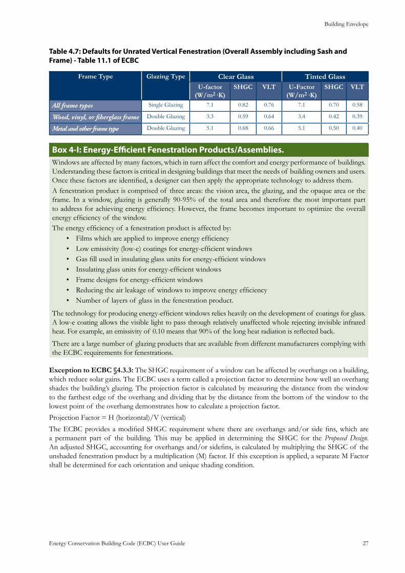
Building Envelope
Energy Conservation Building Code (ECBC) User Guide 27
: Defaults for Unrated Vertical Fenestration (Overall Assembly including Sash and Table 4.7Frame) - Table 11.1 of ECBC
Frame Type Glazing Type Clear Glass Tinted GlassU-factor
(W/m2·K)SHGC VLT U-Factor
(W/m2·K)SHGC VLT
All frame types Single Glazing 7.1 0.82 0.76 7.1 0.70 0.58
Wood, vinyl, or fiberglass frame Double Glazing 3.3 0.59 0.64 3.4 0.42 0.39
Metal and other frame type Double Glazing 5.1 0.68 0.66 5.1 0.50 0.40
: Energy-Efficient Fenestration Products/Assemblies.Box 4-IWindows are affected by many factors, which in turn affect the comfort and energy performance of buildings. Understanding these factors is critical in designing buildings that meet the needs of building owners and users. Once these factors are identified, a designer can then apply the appropriate technology to address them.A fenestration product is comprised of three areas: the vision area, the glazing, and the opaque area or the frame. In a window, glazing is generally 90-95% of the total area and therefore the most important part to address for achieving energy efficiency. However, the frame becomes important to optimize the overall energy efficiency of the window. The energy efficiency of a fenestration product is affected by:
Films which are applied to improve energy efficiency • Low emissivity (low-e) coatings for energy-efficient windows • Gas fill used in insulating glass units for energy-efficient windows • Insulating glass units for energy-efficient windows • Frame designs for energy-efficient windows • Reducing the air leakage of windows to improve energy efficiency • Number of layers of glass in the fenestration product.•
The technology for producing energy-efficient windows relies heavily on the development of coatings for glass. A low-e coating allows the visible light to pass through relatively unaffected whole rejecting invisible infrared heat. For example, an emissivity of 0.10 means that 90% of the long heat radiation is reflected back.
There are a large number of glazing products that are available from different manufacturers complying with the ECBC requirements for fenestrations.
Exception to ECBC §4.3.3: The SHGC requirement of a window can be affected by overhangs on a building, which reduce solar gains. The ECBC uses a term called a projection factor to determine how well an overhang shades the building’s glazing. The projection factor is calculated by measuring the distance from the window to the farthest edge of the overhang and dividing that by the distance from the bottom of the window to the lowest point of the overhang demonstrates how to calculate a projection factor.
Projection Factor = H (horizontal)/V (vertical)
The ECBC provides a modified SHGC requirement where there are overhangs and/or side fins, which are a permanent part of the building. This may be applied in determining the SHGC for the Proposed Design. An adjusted SHGC, accounting for overhangs and/or sidefins, is calculated by multiplying the SHGC of the unshaded fenestration product by a multiplication (M) factor. If this exception is applied, a separate M Factor shall be determined for each orientation and unique shading condition.
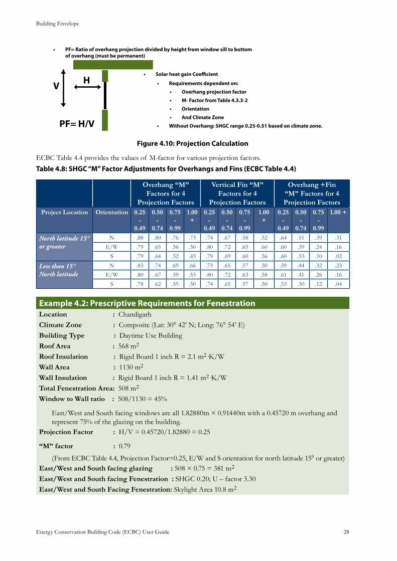
Building Envelope
Energy Conservation Building Code (ECBC) User Guide 28
Solar heat gain Coefficient•
Requirements dependent on:•
Overhang projection factor•
M- Factor from Table 4.3.3-2•
Orientation•
And Climate Zone•
Without Overhang: SHGC range 0.25-0.51 based on climate zone.•
PF= Ratio of overhang projection divided by height from window sill to bottom •of overhang (must be permanent)
: Projection CalculationFigure 4.10
ECBC Table 4.4 provides the values of M-factor for various projection factors.
Table 4.8: SHGC “M” Factor Adjustments for Overhangs and Fins (ECBC Table 4.4)
Overhang “M” Factors for 4
Projection Factors
Vertical Fin “M” Factors for 4
Projection Factors
Overhang +Fin “M” Factors for 4 Projection Factors
Project Location Orientation 0.25 -
0.49
0.50 -
0.74
0.75 -
0.99
1.00 +
0.25 -
0.49
0.50 -
0.74
0.75 -
0.99
1.00 +
0.25 -
0.49
0.50 -
0.74
0.75 -
0.99
1.00 +
North latitude 15° or greater
N .88 .80 .76 .73 .74 .67 .58 .52 .64 .51 .39 .31
E/W .79 .65 .56 .50 .80 .72 .65 .60 .60 .39 .24 .16
S .79 .64 .52 .43 .79 .69 .60 .56 .60 .33 .10 .02
Less than 15° North latitude
N .83 .74 .69 .66 .73 .65 .57 .50 .59 .44 .32 .23
E/W .80 .67 .59 .53 .80 .72 .63 .58 .61 .41 .26 .16
S .78 .62 .55 .50 .74 .65 .57 .50 .53 .30 .12 .04
: Prescriptive Requirements for FenestrationExample 4.2Location : ChandigarhClimate Zone : Composite (Lat: 30° 42’ N; Long: 76° 54’ E)Building Type : Daytime Use BuildingRoof Area : 568 m2
Roof Insulation : Rigid Board 1 inch R = 2.1 m2·K/WWall Area : 1130 m2
Wall Insulation : Rigid Board 1 inch R = 1.41 m2·K/WTotal Fenestration Area: 508 m2
Window to Wall ratio : 508/1130 = 45%
East/West and South facing windows are all 1.82880m × 0.91440m with a 0.45720 m overhang and represent 75% of the glazing on the building.
Projection Factor : H/V = 0.45720/1.82880 = 0.25
“M” factor : 0.79
(From ECBC Table 4.4, Projection Factor=0.25, E/W and S orientation for north latitude 15° or greater)East/West and South facing glazing : 508 × 0.75 = 381 m2
East/West and South facing Fenestration : SHGC 0.20; U – factor 3.30East/West and South Facing Fenestration: Skylight Area 10.8 m2
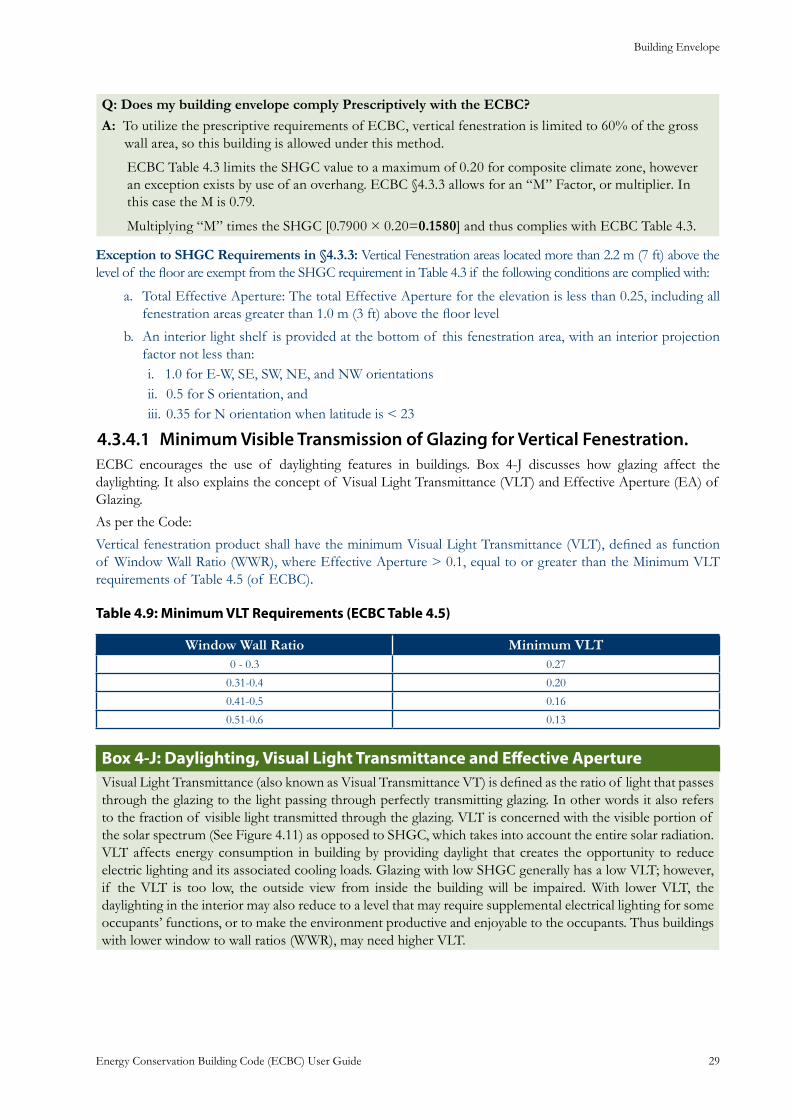
Building Envelope
Energy Conservation Building Code (ECBC) User Guide 29
Q: Does my building envelope comply Prescriptively with the ECBC?A: To utilize the prescriptive requirements of ECBC, vertical fenestration is limited to 60% of the gross
wall area, so this building is allowed under this method.
ECBC Table 4.3 limits the SHGC value to a maximum of 0.20 for composite climate zone, however an exception exists by use of an overhang. ECBC §4.3.3 allows for an “M” Factor, or multiplier. In this case the M is 0.79.
Multiplying “M” times the SHGC [0.7900 × 0.20=0.1580] and thus complies with ECBC Table 4.3.
Exception to SHGC Requirements in §4.3.3: Vertical Fenestration areas located more than 2.2 m (7 ft) above the level of the floor are exempt from the SHGC requirement in Table 4.3 if the following conditions are complied with:
Total Effective Aperture: The total Effective Aperture for the elevation is less than 0.25, including all a. fenestration areas greater than 1.0 m (3 ft) above the floor level
An interior light shelf is provided at the bottom of this fenestration area, with an interior projection b. factor not less than:
1.0 for E-W, SE, SW, NE, and NW orientationsi. 0.5 for S orientation, andii. 0.35 for N orientation when latitude is < 23iii.
Minimum Visible Transmission of Glazing for Vertical Fenestration.4.3.4.1 ECBC encourages the use of daylighting features in buildings. Box 4-J discusses how glazing affect the daylighting. It also explains the concept of Visual Light Transmittance (VLT) and Effective Aperture (EA) of Glazing.
As per the Code:
Vertical fenestration product shall have the minimum Visual Light Transmittance (VLT), defined as function of Window Wall Ratio (WWR), where Effective Aperture > 0.1, equal to or greater than the Minimum VLT requirements of Table 4.5 (of ECBC).
: Minimum VLT Requirements (ECBC Table 4.5)Table 4.9
Window Wall Ratio Minimum VLT0 - 0.3 0.27
0.31-0.4 0.20
0.41-0.5 0.16
0.51-0.6 0.13
: Daylighting, Visual Light Transmittance and Effective ApertureBox 4-JVisual Light Transmittance (also known as Visual Transmittance VT) is defined as the ratio of light that passes through the glazing to the light passing through perfectly transmitting glazing. In other words it also refers to the fraction of visible light transmitted through the glazing. VLT is concerned with the visible portion of the solar spectrum (See Figure 4.11) as opposed to SHGC, which takes into account the entire solar radiation. VLT affects energy consumption in building by providing daylight that creates the opportunity to reduce electric lighting and its associated cooling loads. Glazing with low SHGC generally has a low VLT; however, if the VLT is too low, the outside view from inside the building will be impaired. With lower VLT, the daylighting in the interior may also reduce to a level that may require supplemental electrical lighting for some occupants’ functions, or to make the environment productive and enjoyable to the occupants. Thus buildings with lower window to wall ratios (WWR), may need higher VLT.
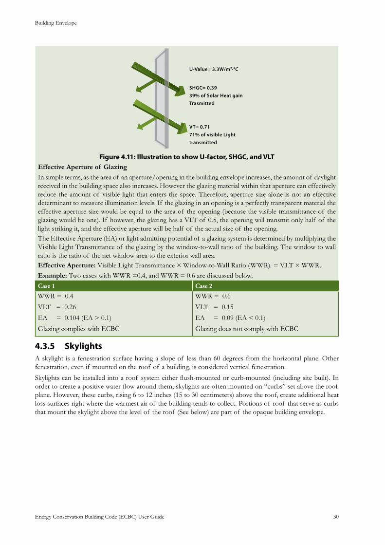
Building Envelope
Energy Conservation Building Code (ECBC) User Guide 30
: Illustration to show U-factor, SHGC, and VLTFigure 4.11Effective Aperture of GlazingIn simple terms, as the area of an aperture/opening in the building envelope increases, the amount of daylight received in the building space also increases. However the glazing material within that aperture can effectively reduce the amount of visible light that enters the space. Therefore, aperture size alone is not an effective determinant to measure illumination levels. If the glazing in an opening is a perfectly transparent material the effective aperture size would be equal to the area of the opening (because the visible transmittance of the glazing would be one). If however, the glazing has a VLT of 0.5, the opening will transmit only half of the light striking it, and the effective aperture will be half of the actual size of the opening.The Effective Aperture (EA) or light admitting potential of a glazing system is determined by multiplying the Visible Light Transmittance of the glazing by the window-to-wall ratio of the building. The window to wall ratio is the ratio of the net window area to the exterior wall area. Effective Aperture: Visible Light Transmittance × Window-to-Wall Ratio (WWR). = VLT × WWR.Example: Two cases with WWR =0.4, and WWR = 0.6 are discussed below.Case 1 Case 2
WWR = 0.4
VLT = 0.26
EA = 0.104 (EA > 0.1)
Glazing complies with ECBC
WWR = 0.6
VLT = 0.15
EA = 0.09 (EA < 0.1)
Glazing does not comply with ECBC
Skylights4.3.5 A skylight is a fenestration surface having a slope of less than 60 degrees from the horizontal plane. Other fenestration, even if mounted on the roof of a building, is considered vertical fenestration.
Skylights can be installed into a roof system either flush-mounted or curb-mounted (including site built). In order to create a positive water flow around them, skylights are often mounted on “curbs” set above the roof plane. However, these curbs, rising 6 to 12 inches (15 to 30 centimeters) above the roof, create additional heat loss surfaces right where the warmest air of the building tends to collect. Portions of roof that serve as curbs that mount the skylight above the level of the roof (See below) are part of the opaque building envelope.
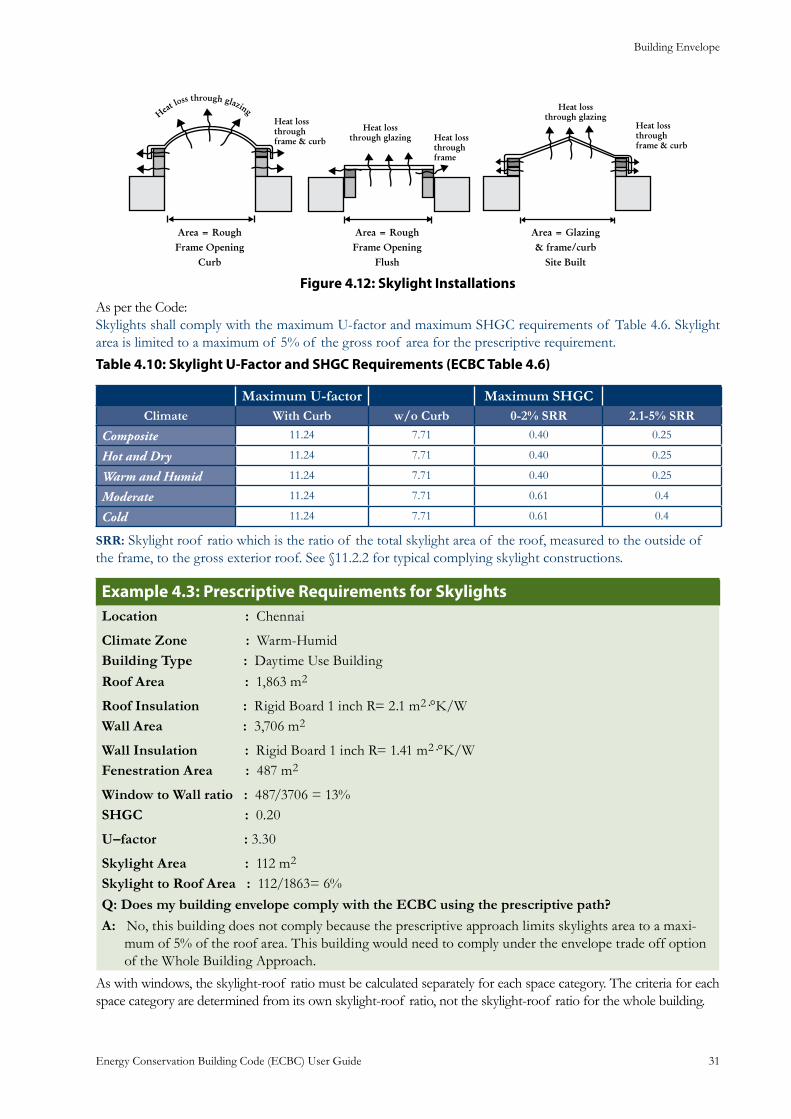
Building Envelope
Energy Conservation Building Code (ECBC) User Guide 31
: Skylight InstallationsFigure 4.12
As per the Code:Skylights shall comply with the maximum U-factor and maximum SHGC requirements of Table 4.6. Skylight area is limited to a maximum of 5% of the gross roof area for the prescriptive requirement.
: Skylight U-Factor and SHGC Requirements (ECBC Table 4.6)Table 4.10
Maximum U-factor Maximum SHGCClimate With Curb w/o Curb 0-2% SRR 2.1-5% SRR
Composite 11.24 7.71 0.40 0.25
Hot and Dry 11.24 7.71 0.40 0.25
Warm and Humid 11.24 7.71 0.40 0.25
Moderate 11.24 7.71 0.61 0.4
Cold 11.24 7.71 0.61 0.4
SRR: Skylight roof ratio which is the ratio of the total skylight area of the roof, measured to the outside of the frame, to the gross exterior roof. See §11.2.2 for typical complying skylight constructions.
: Prescriptive Requirements for SkylightsExample 4.3Location : Chennai
Climate Zone : Warm-HumidBuilding Type : Daytime Use BuildingRoof Area : 1,863 m2
Roof Insulation : Rigid Board 1 inch R= 2.1 m2·°K/WWall Area : 3,706 m2
Wall Insulation : Rigid Board 1 inch R= 1.41 m2·°K/WFenestration Area : 487 m2
Window to Wall ratio : 487/3706 = 13%SHGC : 0.20
U–factor : 3.30
Skylight Area : 112 m2
Skylight to Roof Area : 112/1863= 6%Q: Does my building envelope comply with the ECBC using the prescriptive path?A: No, this building does not comply because the prescriptive approach limits skylights area to a maxi-
mum of 5% of the roof area. This building would need to comply under the envelope trade off option of the Whole Building Approach.
As with windows, the skylight-roof ratio must be calculated separately for each space category. The criteria for each space category are determined from its own skylight-roof ratio, not the skylight-roof ratio for the whole building.
Building Envelope
Energy Conservation Building Code (ECBC) User Guide 32
: Glazing Selection for ECBC ComplianceBox 4-KWhat is the most important feature that a building professional should look for regarding windows, doors, and skylights?
The SHGC and U-factor ratings are the most important items to verify during inspections. Building professionals should verify that the ratings of the installed windows, doors, and skylights meet or exceed the ratings specified on the plans. It is also important to verify that the same window area has been installed as the area shown on the plans and that the glass orientation on the plans and building are consistent.What is Solar Heat Gain Coefficient?
The Solar Heat Gain Coefficient is a measure of the percentage of heat from the sun that gets through a window or other fenestration product. The SHGC is expressed as a number between 0 and 1. The lower a window’s SHGC, the less solar heat it transmits to the interior of the building. SHGC can also refer to shading so the lower the SHGC the more effective the product is at shading the heat gain from entering the interior.What is low-e glass?Low-e stands for low-emissivity and refers to a special coating that reduces the heat transfer of a window assembly. Low-e coated products that reduce solar heat gain can be produced by adding a metallic coating either while the glass is in a molten state or by applying to the glass after it has cooled to a solid state. Low-e glass is readily available from all the glass and window manufacturers. The coatings typically add about 10% to the cost of a window but costs vary by product type, by manufacturer, by retailer and by location.What is spectrally selective glass?The sun emits visible solar radiation in the form of light and infrared radiation that cannot be seen, but causes heat. Spectrally selective glass transmits a high proportion of the visible solar radiation, but screens out radiant heat from the sun – significantly reducing the need to cool a building’s interior. Spectrally selective glass is used to describe low-e coated glass that lowers the SHGC.How can I be sure I have spectrally selective glass?The SHGC rating for the product is the key to determining whether you have glass with a spectrally selective coating. In general, windows with a spectrally selective low-e coating will have SHGC ratings of 0.40 or lower.
Building Envelope Trade-Off Option 4.4 This is a systems-based approach, where the thermal performance of individual envelope components can be reduced if compensated by higher efficiency in other building components (i.e., using higher wall insulation could allow for a less stringent U-factor requirement for windows, or vice versa.) These trade-offs typically occur within major building systems – roofs, walls, fenestration, overhangs etc.
This method offers the designer more flexibility than strictly following the prescribed values for individual elements. The thermal performance of one envelope component such as the roof can fail to meet the prescriptive requirements as long as other components perform better than what is required. Trade-offs are permitted only between building envelope components. It is not possible, for instance, to make trade-offs against improvements in the lighting or HVAC systems. However, this makes using the envelope trade-off option more complicated than the prescriptive method. It is necessary to calculate the surface area of each exterior and semi-exterior surface; all areas must also be calculated separately for each orientation. The equations used for calculating envelope performance factor under envelope trade-offs are documented in ECBC §12 Appendix D.
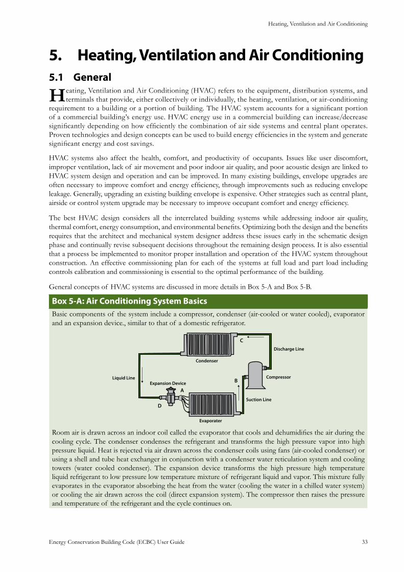
Heating, Ventilation and Air Conditioning
Energy Conservation Building Code (ECBC) User Guide 33
Heating, Ventilation and Air Conditioning5. General5.1
Heating, Ventilation and Air Conditioning (HVAC) refers to the equipment, distribution systems, and terminals that provide, either collectively or individually, the heating, ventilation, or air-conditioning
requirement to a building or a portion of building. The HVAC system accounts for a significant portion of a commercial building’s energy use. HVAC energy use in a commercial building can increase/decrease significantly depending on how efficiently the combination of air side systems and central plant operates. Proven technologies and design concepts can be used to build energy efficiencies in the system and generate significant energy and cost savings.
HVAC systems also affect the health, comfort, and productivity of occupants. Issues like user discomfort, improper ventilation, lack of air movement and poor indoor air quality, and poor acoustic design are linked to HVAC system design and operation and can be improved. In many existing buildings, envelope upgrades are often necessary to improve comfort and energy efficiency, through improvements such as reducing envelope leakage. Generally, upgrading an existing building envelope is expensive. Other strategies such as central plant, airside or control system upgrade may be necessary to improve occupant comfort and energy efficiency.
The best HVAC design considers all the interrelated building systems while addressing indoor air quality, thermal comfort, energy consumption, and environmental benefits. Optimizing both the design and the benefits requires that the architect and mechanical system designer address these issues early in the schematic design phase and continually revise subsequent decisions throughout the remaining design process. It is also essential that a process be implemented to monitor proper installation and operation of the HVAC system throughout construction. An effective commissioning plan for each of the systems at full load and part load including controls calibration and commissioning is essential to the optimal performance of the building.
General concepts of HVAC systems are discussed in more details in Box 5-A and Box 5-B.
Box 5-A: Air Conditioning System BasicsBasic components of the system include a compressor, condenser (air-cooled or water cooled), evaporator and an expansion device., similar to that of a domestic refrigerator.
Discharge Line
Compressor
Suction Line
Evaporater
Condenser
Expansion DeviceLiquid Line
A
B
C
D
Room air is drawn across an indoor coil called the evaporator that cools and dehumidifies the air during the cooling cycle. The condenser condenses the refrigerant and transforms the high pressure vapor into high pressure liquid. Heat is rejected via air drawn across the condenser coils using fans (air-cooled condenser) or using a shell and tube heat exchanger in conjunction with a condenser water reticulation system and cooling towers (water cooled condenser). The expansion device transforms the high pressure high temperature liquid refrigerant to low pressure low temperature mixture of refrigerant liquid and vapor. This mixture fully evaporates in the evaporator absorbing the heat from the water (cooling the water in a chilled water system) or cooling the air drawn across the coil (direct expansion system). The compressor then raises the pressure and temperature of the refrigerant and the cycle continues on.

Heating, Ventilation and Air Conditioning
Energy Conservation Building Code (ECBC) User Guide 34
: Heating SystemsBox 5-BHeating system types can be classified fairly well by the heating equipment type. The heating equipment used in buildings includes boilers (oil and gas), furnaces (oil, gas, and electric), heat pumps, and space heaters.
Boiler-based heating systems have steam and/or water piping to distribute heat. Boilers can be self-contained units, or they can be packaged units which are factory-built systems, disassembled for shipment, and reassembled at the site. The heated water may serve preheat coils in air handling units; reheat coils, and local radiators. Systems that circulate water or a fluid are called hydronic systems. Heating water may also be used for heating of service water and other process needs, depending on the building type. Some central systems have steam boilers rather than hot water boilers because of the need for steam for conditioning needs (humidifiers in air-handling units) or process needs (sterilizers in hospitals, direct-injection heating in laundries and dishwashers, etc.). The remaining heating systems include heat pumps and space heaters that heat directly and require little or no distribution.
Mandatory Requirements5.2 The Code contains mandatory requirements for the following elements of the HVAC system:
Natural Ventilation• Equipment Efficiency • Controls• Piping and Ductwork• System Balancing.• Condensers• Economizers• Hydronic Systems•
Natural Ventilation5.2.1 As per the Code:
Natural ventilation (of buildings) shall comply with the design guidelines provided for natural ventilation in the National Building Code of India 2005,(NBC, 2005) Part 8, 5.4.3 and 5.7.1
These guidelines from NBC, 2005 have been reproduced below in Box 5-C, keeping in view the philosophy behind this Guide to include ECBC-referenced material in the Guide. However, the exact relevance of these general guidelines in the design of commercial buildings need to be critically examined.
Box 5-C: Design Guidelines for Natural VentilationBy Wind Action
Building need not necessarily be oriented perpendicular to the prevailing outdoor wind; it may be i. oriented at any convenient angle between 0° and 30° without losing any beneficial aspect of the breeze. If the prevailing wind is from east or west, building may be oriented at 45° to the incident wind so as to diminish the solar heat without much reduction in air motion indoors. Inlet openings in the buildings should be well distributed and should be located on the windward ii. side at a low level, and outlet openings should be located on the leeward side. Inlet and outlet openings at high levels may only clear the top air at that level without producing air movement at the level of occupancy. Maximum air movement at a particular plane is achieved by keeping the sill height of the opening iii. at 85% of the critical height (such as head level) for the following recommended levels of occupancy:
For sitting on chair 0.75 m1. For sitting on bed 0.60 m2.
Heating, Ventilation and Air Conditioning
Energy Conservation Building Code (ECBC) User Guide 35
For sitting on floor 0.40 m3.
Inlet openings should not, as far as possible, be obstructed by adjoining buildings, trees, sign iv. boards or other obstructions or by partitions inside in the path of air flow. In rooms of normal size having identical windows on opposite walls the average indoor air speed v. increases rapidly by increasing the width of the window up to two-thirds of the wall width; beyond that the increase is in much smaller proportion than the increase of the window width. The air motion in the working zone is maximum when window height is 1.1 m. Further increase in window height promotes air motion at higher level of window, but does not contribute additional benefits as regards air motion in the occupancy zones in buildings. Greatest flow per unit area of openings is obtained by using inlet and outlet openings of nearby equal areas vi. at the same level. For a total area of openings (inlet and outlet) of 20% to 30% of floor area, the average indoor vii. wind velocity is around 30% of outdoor velocity. Further increase in window size increases the available velocity but not in the same proportion. In fact, even under most favorable conditions the maximum average indoor wind speed does not exceed 40% of outdoor velocity. Where the direction of wind is quite constant and dependable, the size of the inlet should be kept viii. within 30 to 50% of the total area of openings and the building should be oriented perpendicular to the incident wind. Where direction of the wind is quite variable, the openings may be arranged so that as far as possible there is approximately equal area on all sides. Thus no matter what the wind direction is, there would be some openings directly exposed to wind pressure and others to air suction and effective air movement through the building would be assured. Windows of living rooms should open directly to an open space. In places where building sites are ix. restricted, open space may have to be created in the buildings by providing adequate courtyards. In the case of rooms with only one wall exposed to outside, provision of two windows on that wall x. is preferred to that of a single window. Windows located diagonally opposite to each other with the windward window near the upstream xi. comer give better performance than other window arrangements for most of the building orientations. Horizontal louvers, that is a sunshade, atop a window deflects the incident wind upward and xii. reduces air motion in the zone of occupancy. A horizontal slot between the wall and horizontal louver prevents upward deflection of air in the interior of rooms. Provision of inverted L type (r) louver increases the room air motion provided that the vertical projection does not obstruct the incident wind. Provision of horizontal sashes inclined at an angle of 45° in appropriate direction helps to promote xiii. the indoor air motion. Sashes projecting outward are more effective than projecting inward. Air motion at working plane 0.4 m above the floor can be enhanced by 30% using a pelmet type xiv. wind deflector. Roof overhangs help by promoting air motion in the working zone inside buildings. xv. Verandah open on three sides is to be preferred since it causes an increase in the room air motion xvi. for most of the orientations of the building with respect to the outdoor wind. A partition placed parallel to the incident wind has little influence on the pattern of the air flow, but xvii. when located perpendicular to the main flow, the same partition creates a wind shadow. Provision of a partition with spacing of 0.3 m underneath helps by augmenting air motion near floor level in the leeward compartment of wide span buildings. Air motion in a building unit having windows tangential to the incident wind is accelerated when xviii. unit is located at end-on position on downstream side. Air motion in two wings oriented parallel to the prevailing breeze is promoted by connecting them xix. with a block on downstream side. Air motion in a building is not affected by constructing another building of equal or smaller height xx. on the leeward side; but it is slightly reduced if the leeward building is taller than the windward block.

Heating, Ventilation and Air Conditioning
Energy Conservation Building Code (ECBC) User Guide 36
Air motion in a shielded building is less than that in an unobstructed building. To minimize the xxi. shielding effect, the distances between two rows should be 8H for semi-detached houses and 10H for long rows houses. However, for smaller spacing the shielding effect is also diminished by raising the height of the shielded building. Hedges and shrubs deflect the air away from the inlet openings and cause a reduction in indoor xxii. air motion. These elements should not be planted at a distance of about 8m from the building because the induced air motion is reduced to minimum in that case. However, air motion in the leeward part of the building can be enhanced by planting a low hedge at a distance of 2m from the building. Trees with large foliage mass having trunk bare of branches up to the top level of window, deflect xxiii. the outdoor wind downwards and promotes air motion in the leeward portion of buildings. Ventilation conditions indoors can be ameliorated by constructing buildings on earth mound xxiv. having a slant surface with a slope of 10° on the upstream side. In case of industrial buildings the window height should be about 1.6m and the width about two-xxv. thirds of wall width. These should be located at a height of 1.1m above the floor. In addition, openings around 0.9m high should be provided over two-thirds of the length of the glazed area in the roof lights. Height of industrial buildings, although determined by the requirements of industrial processes xxvi. involved, generally kept large enough to protect the workers against hot stagnant air below the ceiling as also to dilute the concentration of contaminant inside. However, if high level openings in roof or walls are provided, building height can be reduced to 4m without in any way impairing the ventilation performance.
By Stack Effect Natural ventilation by stack effect occurs when air inside a building is at a different temperature than air outside. Thus, in heated buildings or in buildings wherein hot processes are carried out and in ordinary buildings during summer nights and during premonsoon periods, when the inside temperature is higher than that of outside, cool outside air will tend to enter through openings at low level and warm air will tend to leave through openings at high level. It would, therefore, be advantageous to provide ventilators as close to ceilings as possible. Ventilators can also be provided in roofs as, for example, cowl, ventpipe, covered roof and ridge vent. Energy Conservation in Ventilation System Maximum possible use should be made of wind-induced natural ventilation. This may be accom-plished by following the design guidelines
Adequate number of circulating fans should be installed to serve all interior working areas during i. the summer months in the hot dry and warm humid regions to provide necessary air movement at times when ventilation due to wind action alone does not afford sufficient relief. The capacity of a ceiling fan to meet the requirement of a room with the longer dimension D ii. meters should be about 55D m3/min. The height of fan blades above the floor should be (3H + W)/4, where H is the height of the iii. room, and W is the height of the work plane. The minimum distance between fan blades and the ceiling should be about 0.3 meters. iv. Electronic regulators should be used instead of resistance type regulators for controlling the speed v. of fans. When actual ventilated zone does not cover the entire room area, then optimum size of ceiling fan vi. should be chosen based on the actual usable area of room, rather than the total floor area of the room. Thus smaller size of fan can be employed and energy saving could be achieved. Power consumption by larger fans is obviously higher, but their power consumption per square vii. meter of floor area is less and service value higher. Evidently, improper use of fans irrespective of the rooms dimensions is likely to result in higher power consumption. From the point of view of energy consumption, the number of fans and the optimum sizes for rooms of different dimensions are given in the following table:
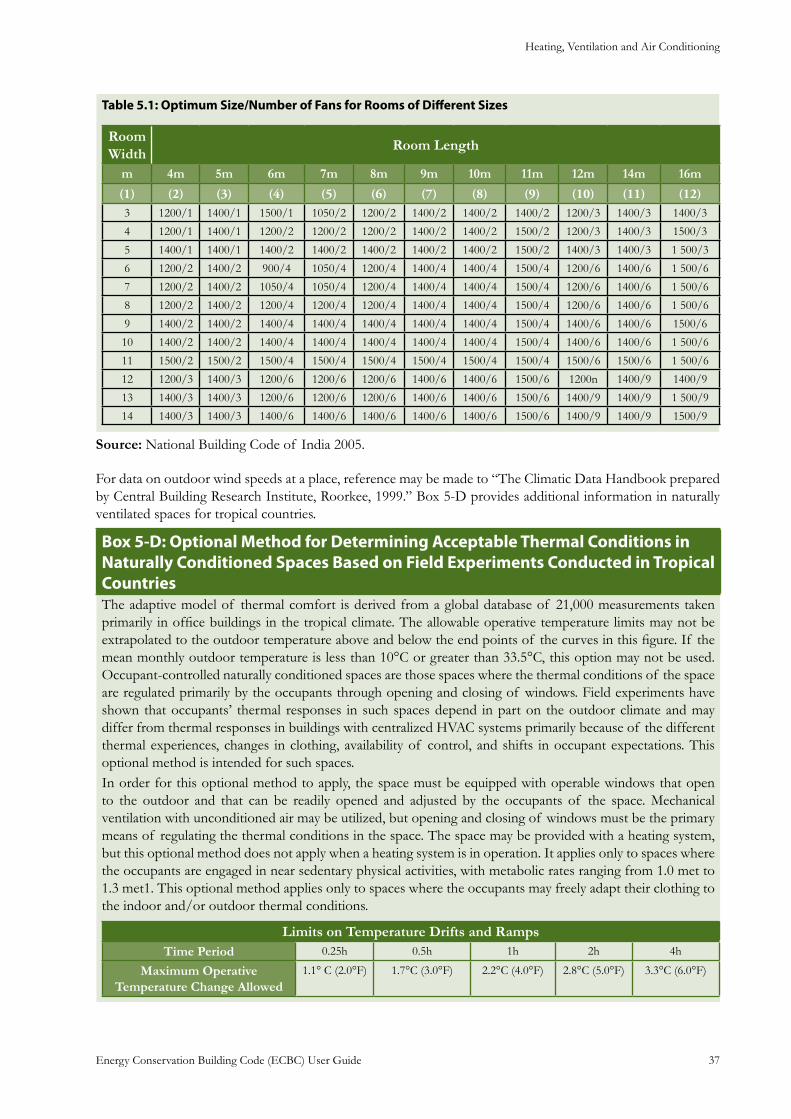
Heating, Ventilation and Air Conditioning
Energy Conservation Building Code (ECBC) User Guide 37
: Optimum Size/Number of Fans for Rooms of Different SizesTable 5.1
Room Width
Room Length
m 4m 5m 6m 7m 8m 9m 10m 11m 12m 14m 16m
(1) (2) (3) (4) (5) (6) (7) (8) (9) (10) (11) (12) 3 1200/1 1400/1 1500/1 1050/2 1200/2 1400/2 1400/2 1400/2 1200/3 1400/3 1400/3
4 1200/1 1400/1 1200/2 1200/2 1200/2 1400/2 1400/2 1500/2 1200/3 1400/3 1500/3
5 1400/1 1400/1 1400/2 1400/2 1400/2 1400/2 1400/2 1500/2 1400/3 1400/3 1 500/3
6 1200/2 1400/2 900/4 1050/4 1200/4 1400/4 1400/4 1500/4 1200/6 1400/6 1 500/6
7 1200/2 1400/2 1050/4 1050/4 1200/4 1400/4 1400/4 1500/4 1200/6 1400/6 1 500/6
8 1200/2 1400/2 1200/4 1200/4 1200/4 1400/4 1400/4 1500/4 1200/6 1400/6 1 500/6
9 1400/2 1400/2 1400/4 1400/4 1400/4 1400/4 1400/4 1500/4 1400/6 1400/6 1500/6
10 1400/2 1400/2 1400/4 1400/4 1400/4 1400/4 1400/4 1500/4 1400/6 1400/6 1 500/6
11 1500/2 1500/2 1500/4 1500/4 1500/4 1500/4 1500/4 1500/4 1500/6 1500/6 1 500/6
12 1200/3 1400/3 1200/6 1200/6 1200/6 1400/6 1400/6 1500/6 1200n 1400/9 1400/9
13 1400/3 1400/3 1200/6 1200/6 1200/6 1400/6 1400/6 1500/6 1400/9 1400/9 1 500/9
14 1400/3 1400/3 1400/6 1400/6 1400/6 1400/6 1400/6 1500/6 1400/9 1400/9 1500/9
Source: National Building Code of India 2005.
For data on outdoor wind speeds at a place, reference may be made to “The Climatic Data Handbook prepared by Central Building Research Institute, Roorkee, 1999.” Box 5-D provides additional information in naturally ventilated spaces for tropical countries.
: Optional Method for Determining Acceptable Thermal Conditions in Box 5-DNaturally Conditioned Spaces Based on Field Experiments Conducted in Tropical CountriesThe adaptive model of thermal comfort is derived from a global database of 21,000 measurements taken primarily in office buildings in the tropical climate. The allowable operative temperature limits may not be extrapolated to the outdoor temperature above and below the end points of the curves in this figure. If the mean monthly outdoor temperature is less than 10°C or greater than 33.5°C, this option may not be used. Occupant-controlled naturally conditioned spaces are those spaces where the thermal conditions of the space are regulated primarily by the occupants through opening and closing of windows. Field experiments have shown that occupants’ thermal responses in such spaces depend in part on the outdoor climate and may differ from thermal responses in buildings with centralized HVAC systems primarily because of the different thermal experiences, changes in clothing, availability of control, and shifts in occupant expectations. This optional method is intended for such spaces.In order for this optional method to apply, the space must be equipped with operable windows that open to the outdoor and that can be readily opened and adjusted by the occupants of the space. Mechanical ventilation with unconditioned air may be utilized, but opening and closing of windows must be the primary means of regulating the thermal conditions in the space. The space may be provided with a heating system, but this optional method does not apply when a heating system is in operation. It applies only to spaces where the occupants are engaged in near sedentary physical activities, with metabolic rates ranging from 1.0 met to 1.3 met1. This optional method applies only to spaces where the occupants may freely adapt their clothing to the indoor and/or outdoor thermal conditions.
Limits on Temperature Drifts and RampsTime Period 0.25h 0.5h 1h 2h 4h
Maximum Operative Temperature Change Allowed
1.1° C (2.0°F) 1.7°C (3.0°F) 2.2°C (4.0°F) 2.8°C (5.0°F) 3.3°C (6.0°F)
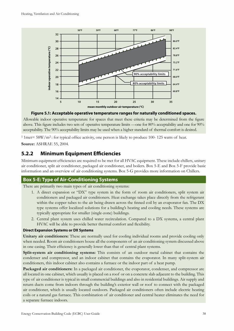
Heating, Ventilation and Air Conditioning
Energy Conservation Building Code (ECBC) User Guide 38
: Acceptable operative temperature ranges for naturally conditioned spaces.Figure 5.1Allowable indoor operative temperature for spaces that meet these criteria may be determined from the figure above. This figure includes two sets of operative temperature limits —one for 80% acceptability and one for 90% acceptability. The 90% acceptability limits may be used when a higher standard of thermal comfort is desired.
1 1met= 58W/m2 : for typical office activity, one person is likely to produce 100- 125 watts of heat.
Source: ASHRAE 55, 2004.
Minimum Equipment Efficiencies5.2.2 Minimum equipment efficiencies are required to be met for all HVAC equipment. These include chillers, unitary air conditioner, split air conditioner, packaged air conditioner, and boilers. Box 5-E and Box 5-F provide basic information and an overview of air conditioning systems. Box 5-G provides more information on Chillers.
: Type of Air-Conditioning Systems Box 5-EThere are primarily two main types of air conditioning systems:
A direct expansion or “DX” type system in the form of room air conditioners, split system air 1. conditioners and packaged air conditioners. Heat exchange takes place directly from the refrigerant within the copper tubes to the air being drawn across the finned coil by an evaporator fan. The DX type systems offer localized solutions for a building’s heating and cooling needs. These systems are typically appropriate for smaller (single-zone) buildings.Central plant system uses chilled water recirculation. Compared to a DX systems, a central plant 2. HVAC will be able to provide better thermal comfort and flexibility.
Direct Expansion Systems or DX SystemsUnitary air conditioners: These are normally used for cooling individual rooms and provide cooling only when needed. Room air conditioners house all the components of an air conditioning system discussed above in one casing. Their efficiency is generally lower than that of central plant systems. Split-system air conditioning systems: This consists of an outdoor metal cabinet that contains the condenser and compressor, and an indoor cabinet that contains the evaporator. In many split-system air conditioners, this indoor cabinet also contains a furnace or the indoor part of a heat pump. Packaged air conditioners: In a packaged air conditioner, the evaporator, condenser, and compressor are all located in one cabinet, which usually is placed on a roof or on a concrete slab adjacent to the building. This type of air conditioner is typical in small commercial buildings and also in residential buildings. Air supply and return ducts come from indoors through the building’s exterior wall or roof to connect with the packaged air conditioner, which is usually located outdoors. Packaged air conditioners often include electric heating coils or a natural gas furnace. This combination of air conditioner and central heater eliminates the need for a separate furnace indoors.
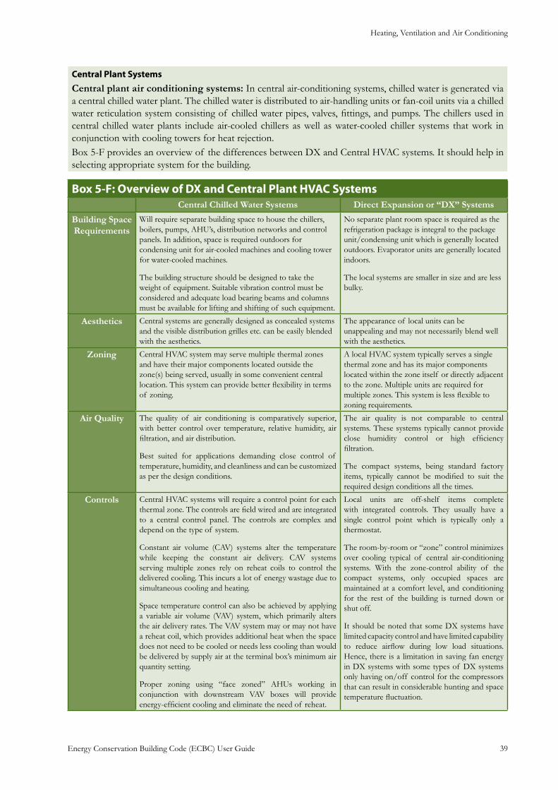
Heating, Ventilation and Air Conditioning
Energy Conservation Building Code (ECBC) User Guide 39
Central Plant SystemsCentral plant air conditioning systems: In central air-conditioning systems, chilled water is generated via a central chilled water plant. The chilled water is distributed to air-handling units or fan-coil units via a chilled water reticulation system consisting of chilled water pipes, valves, fittings, and pumps. The chillers used in central chilled water plants include air-cooled chillers as well as water-cooled chiller systems that work in conjunction with cooling towers for heat rejection.Box 5-F provides an overview of the differences between DX and Central HVAC systems. It should help in selecting appropriate system for the building.
: Overview of DX and Central Plant HVAC SystemsBox 5-FCentral Chilled Water Systems Direct Expansion or “DX” Systems
Building Space Requirements
Will require separate building space to house the chillers, boilers, pumps, AHU’s, distribution networks and control panels. In addition, space is required outdoors for condensing unit for air-cooled machines and cooling tower for water-cooled machines.
The building structure should be designed to take the weight of equipment. Suitable vibration control must be considered and adequate load bearing beams and columns must be available for lifting and shifting of such equipment.
No separate plant room space is required as the refrigeration package is integral to the package unit/condensing unit which is generally located outdoors. Evaporator units are generally located indoors.
The local systems are smaller in size and are less bulky.
Aesthetics Central systems are generally designed as concealed systems and the visible distribution grilles etc. can be easily blended with the aesthetics.
The appearance of local units can be unappealing and may not necessarily blend well with the aesthetics.
Zoning Central HVAC system may serve multiple thermal zones and have their major components located outside the zone(s) being served, usually in some convenient central location. This system can provide better flexibility in terms of zoning.
A local HVAC system typically serves a single thermal zone and has its major components located within the zone itself or directly adjacent to the zone. Multiple units are required for multiple zones. This system is less flexible to zoning requirements.
Air Quality The quality of air conditioning is comparatively superior, with better control over temperature, relative humidity, air filtration, and air distribution.
Best suited for applications demanding close control of temperature, humidity, and cleanliness and can be customized as per the design conditions.
The air quality is not comparable to central systems. These systems typically cannot provide close humidity control or high efficiency filtration.
The compact systems, being standard factory items, typically cannot be modified to suit the required design conditions all the times.
Controls Central HVAC systems will require a control point for each thermal zone. The controls are field wired and are integrated to a central control panel. The controls are complex and depend on the type of system.
Constant air volume (CAV) systems alter the temperature while keeping the constant air delivery. CAV systems serving multiple zones rely on reheat coils to control the delivered cooling. This incurs a lot of energy wastage due to simultaneous cooling and heating.
Space temperature control can also be achieved by applying a variable air volume (VAV) system, which primarily alters the air delivery rates. The VAV system may or may not have a reheat coil, which provides additional heat when the space does not need to be cooled or needs less cooling than would be delivered by supply air at the terminal box’s minimum air quantity setting.
Proper zoning using “face zoned” AHUs working in conjunction with downstream VAV boxes will provide energy-efficient cooling and eliminate the need of reheat.
Local units are off-shelf items complete with integrated controls. They usually have a single control point which is typically only a thermostat.
The room-by-room or “zone” control minimizes over cooling typical of central air-conditioning systems. With the zone-control ability of the compact systems, only occupied spaces are maintained at a comfort level, and conditioning for the rest of the building is turned down or shut off.
It should be noted that some DX systems have limited capacity control and have limited capability to reduce airflow during low load situations. Hence, there is a limitation in saving fan energy in DX systems with some types of DX systems only having on/off control for the compressors that can result in considerable hunting and space temperature fluctuation.
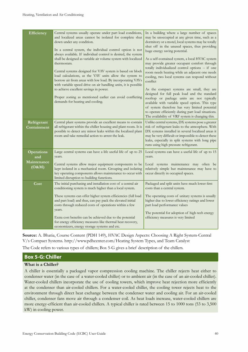
Heating, Ventilation and Air Conditioning
Energy Conservation Building Code (ECBC) User Guide 40
Efficiency Central systems usually operate under part load conditions, and localized areas cannot be isolated for complete shut down under any condition.
In a central system, the individual control option is not always available. If individual control is desired, the system shall be designed as variable air volume system with localized thermostats.
Central systems designed for VAV system is based on block load calculations, as the VAV units allow the system to borrow air from areas with low load. By incorporating VAVs with variable speed drive on air handling units, it is possible to achieve excellent savings in power.
Proper zoning as mentioned earlier can avoid conflicting demands for heating and cooling.
In a building where a large number of spaces may be unoccupied at any given time, such as a dormitory or a motel, local systems may be totally shut off in the unused spaces, thus providing huge energy saving potential.
As a self-contained system, a local HVAC system may provide greater occupant comfort through totally individualized control options -- if one room needs heating while an adjacent one needs cooling, two local systems can respond without conflict
As the compact systems are small, they are designed for full peak load and the standard rooftop or package units are not typically available with variable speed option. This type of system therefore has very limited potential to operate efficiently during part load situations. The availability of VRF system is changing this.
Refrigerant Containment
Central plant systems provide an excellent means to contain all refrigerant within the chiller housing and plant room. It is possible to detect any minor leaks within the localized plant room and take remedial action to arrest the leak.
Unlike central systems, DX systems pose a greater risk of refrigerant leaks to the atmosphere. With DX systems installed in several localized areas it may be very difficult or impossible to detect these leaks, especially in split systems with long pipe runs using high pressure refrigerant.
Operations and
Maintenance (O&M)
Large central systems can have a life useful life of up to 25 years.
Central systems allow major equipment components to be kept isolated in a mechanical room. Grouping and isolating key operating components allows maintenance to occur with limited disruption to building functions.
Local systems can have a useful life of up to 15 years.
Local systems maintenance may often be relatively simple but maintenance may have to occur directly in occupied spaces.
Cost The initial purchasing and installation cost of a central air conditioning system is much higher than a local system.
These systems can offer higher system efficiencies (full load and part load) and thus, can pay pack the elevated initial costs through reduced costs of operations within a few years.
Extra cost benefits can be achieved due to the potential for energy efficiency measures like thermal heat recovery, economizers, energy storage systems and etc.
Packaged and split units have much lower first costs than a central system.
The operating costs of unitary systems is usually higher due to lower efficiency ratings and lower part load performance values
The potential for adoption of high-tech energy efficiency measures is very limited
Source: A. Bhatia, Course Content (PDH 149), HVAC Design Aspects: Choosing A Right System-Central V/s Compact Systems. http://www.pdhcenter.com/Heating System Types, and Team Catalyst
The Code refers to various types of chillers; Box 5-G gives a brief description of the chillers.
: ChillerBox 5-GWhat is a Chiller?A chiller is essentially a packaged vapor compression cooling machine. The chiller rejects heat either to condenser water (in the case of a water-cooled chiller) or to ambient air (in the case of an air-cooled chiller). Water-cooled chillers incorporate the use of cooling towers, which improve heat rejection more efficiently at the condenser than air-cooled chillers. For a water-cooled chiller, the cooling tower rejects heat to the environment through direct heat exchange between the condenser water and cooling air. For an air-cooled chiller, condenser fans move air through a condenser coil. As heat loads increase, water-cooled chillers are more energy-efficient than air-cooled chillers. A typical chiller is rated between 15 to 1000 tons (53 to 3,500 kW) in cooling power.
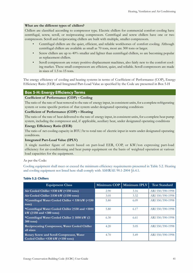
Heating, Ventilation and Air Conditioning
Energy Conservation Building Code (ECBC) User Guide 41
What are the different types of chillers?Chillers are classified according to compressor type. Electric chillers for commercial comfort cooling have centrifugal, screw, scroll, or reciprocating compressors. Centrifugal and screw chillers have one or two compressors. Scroll and reciprocating chillers are built with multiple, smaller compressors.
Centrifugal chillers are the quiet, efficient, and reliable workhorses of comfort cooling. Although • centrifugal chillers are available as small as 70 tons, most are 300 tons or larger.Screw chillers are up to 40% smaller and lighter than centrifugal chillers, so are becoming popular • as replacement chillers.Scroll compressors are rotary positive-displacement machines, also fairly new to the comfort cool-• ing market. These small compressors are efficient, quiet, and reliable. Scroll compressors are made in sizes of 1.5 to 15 tons.
The energy efficiency of cooling and heating systems in terms of Coefficient of Performance (COP), Energy Efficiency Ratio (EER) and Integrated Part-Load Value as specified by the Code are presented in Box 5-H
: Energy Efficiency TermsBox 5-HCoefficient of Performance (COP) – CoolingThe ratio of the rate of heat removal to the rate of energy input, in consistent units, for a complete refrigerating system or some specific portion of that system under designated operating conditionsCoefficient of Performance (COP) – HeatingThe ratio of the rate of heat delivered to the rate of energy input, in consistent units, for a complete heat pump system, including the compressor and, if applicable, auxiliary heat, under designated operating conditionsEnergy Efficiency Ratio (EER)The ratio of net cooling capacity in BTU/hr to total rate of electric input in watts under designated operating conditions.Integrated Part-Load Value (IPLV)A single number figure of merit based on part-load EER, COP, or KW/ton expressing part-load efficiency for air-conditioning and heat pump equipment on the basis of weighted operation at various load capacities for the equipment.
As per the Code:
Cooling equipment shall meet or exceed the minimum efficiency requirements presented in Table 5.2. Heating and cooling equipment not listed here shall comply with ASHRAE 90.1-2004 §6.4.1.
: ChillersTable 5.2
Equipment Class Minimum COP Minimum IPLV Test Standard
Air Cooled Chiller <530 kW (<150 tons) 2.90 3.16 ARI 550/590-1998Air Cooled Chiller ≥530 kW (≥150 tons) 3.05 3.32 ARI 550/590-1998*Centrifugal Water Cooled Chiller < 530 kW (<150 tons)
5.80 6.09 ARI 550/590-1998
*Centrifugal Water Cooled Chiller ≥530 and <1050 kW (≥150 and <300 tons)
5.80 6.17 ARI 550/590-1998
*Centrifugal Water Cooled Chiller ≥ 1050 kW (≥ 300 tons)
6.30 6.61 ARI 550/590-1998
Reciprocating Compressor, Water Cooled Chiller all sizes
4.20 5.05 ARI 550/590-1998
Rotary Screw and Scroll Compressor, Water Cooled Chiller <530 kW (<150 tons)
4.70 5.49 ARI 550/590-1998
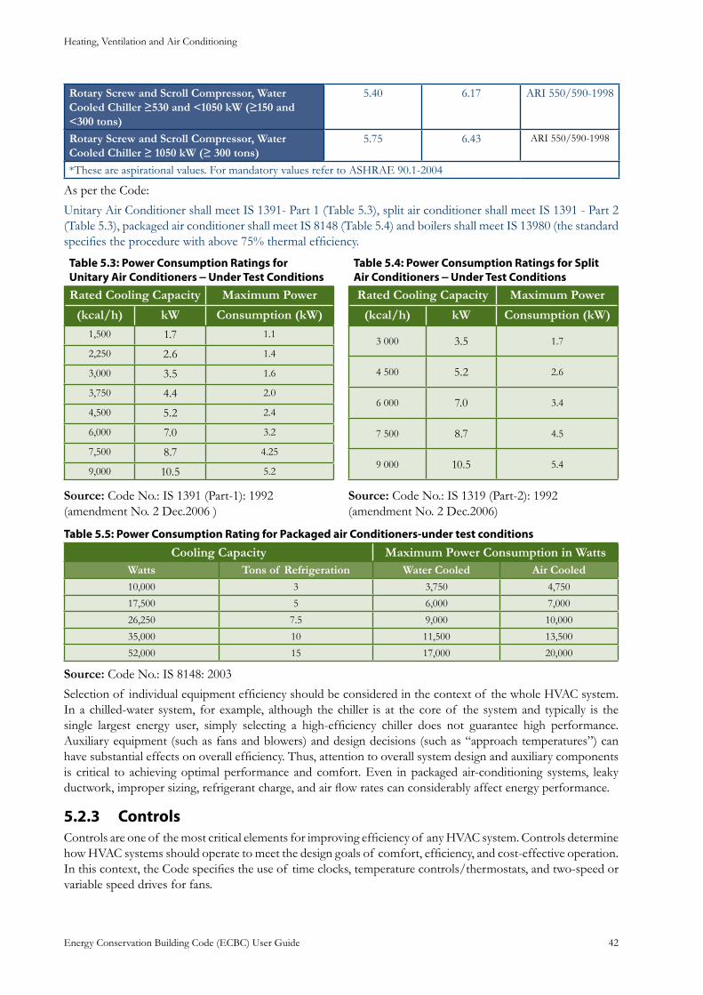
Heating, Ventilation and Air Conditioning
Energy Conservation Building Code (ECBC) User Guide 42
Rotary Screw and Scroll Compressor, Water Cooled Chiller ≥530 and <1050 kW (≥150 and <300 tons)
5.40 6.17 ARI 550/590-1998
Rotary Screw and Scroll Compressor, Water Cooled Chiller ≥ 1050 kW (≥ 300 tons)
5.75 6.43 ARI 550/590-1998
*These are aspirational values. For mandatory values refer to ASHRAE 90.1-2004
As per the Code:
Unitary Air Conditioner shall meet IS 1391- Part 1 (Table 5.3), split air conditioner shall meet IS 1391 - Part 2 (Table 5.3), packaged air conditioner shall meet IS 8148 (Table 5.4) and boilers shall meet IS 13980 (the standard specifies the procedure with above 75% thermal efficiency.
Table 5.3: Power Consumption Ratings for Unitary Air Conditioners – Under Test ConditionsRated Cooling Capacity Maximum Power
(kcal/h) kW Consumption (kW)1,500 1.7 1.1
2,250 2.6 1.4
3,000 3.5 1.6
3,750 4.4 2.0
4,500 5.2 2.4
6,000 7.0 3.2
7,500 8.7 4.25
9,000 10.5 5.2
Table 5.4: Power Consumption Ratings for Split Air Conditioners – Under Test ConditionsRated Cooling Capacity Maximum Power
(kcal/h) kW Consumption (kW)
3 000 3.5 1.7
4 500 5.2 2.6
6 000 7.0 3.4
7 500 8.7 4.5
9 000 10.5 5.4
Source: Code No.: IS 1391 (Part-1): 1992 (amendment No. 2 Dec.2006 )
Source: Code No.: IS 1319 (Part-2): 1992 (amendment No. 2 Dec.2006)
Table 5.5: Power Consumption Rating for Packaged air Conditioners-under test conditions
Cooling Capacity Maximum Power Consumption in WattsWatts Tons of Refrigeration Water Cooled Air Cooled10,000 3 3,750 4,750
17,500 5 6,000 7,000
26,250 7.5 9,000 10,000
35,000 10 11,500 13,500
52,000 15 17,000 20,000
Source: Code No.: IS 8148: 2003
Selection of individual equipment efficiency should be considered in the context of the whole HVAC system. In a chilled-water system, for example, although the chiller is at the core of the system and typically is the single largest energy user, simply selecting a high-efficiency chiller does not guarantee high performance. Auxiliary equipment (such as fans and blowers) and design decisions (such as “approach temperatures”) can have substantial effects on overall efficiency. Thus, attention to overall system design and auxiliary components is critical to achieving optimal performance and comfort. Even in packaged air-conditioning systems, leaky ductwork, improper sizing, refrigerant charge, and air flow rates can considerably affect energy performance.
Controls5.2.3 Controls are one of the most critical elements for improving efficiency of any HVAC system. Controls determine how HVAC systems should operate to meet the design goals of comfort, efficiency, and cost-effective operation. In this context, the Code specifies the use of time clocks, temperature controls/thermostats, and two-speed or variable speed drives for fans.
Heating, Ventilation and Air Conditioning
Energy Conservation Building Code (ECBC) User Guide 43
Timeclock Control 5.2.3.1 As per the Code,
All mechanical cooling and heating systems shall be controlled by a timeclock that:
Can start and stop the system under different schedules for three different day-types per weeka.
Is capable of retaining programming and time setting during loss of power for a period of at least b. 10 hours, and
Includes an accessible manual override that allows temporary operation of the system for up to 2 c. hours
Exceptions to the above are:
Cooling systems < 28 kW (8 tons)a.
Heating systems < 7 kW (2 tons)b.
Temperature Control5.2.3.2 As per the Code:
All heating and cooling equipment shall be temperature controlled. Where a unit provides both heating and cooling, controls shall be capable of providing a temperature dead band of 3°C (5°F) within which the supply of heating and cooling energy to the zone is shut off or reduced to a minimum. Where separate heating and cooling equipment serve the same temperature zone, thermostats shall be interlocked to prevent simultaneous heating and cooling.
It is important to clearly establish design conditions and ensure adequate dead band between cooling and heating set points to avoid conflicting thermostat control conditions. Increasing the dead band can make the system more stable and efficient.
Controls for Cooling Towers and Closed Circuit Fluid Coolers 5.2.3.3 As per the Code:
All cooling towers and closed circuit fluid coolers shall have either two speed motors, pony motors, or variable speed drives controlling the fans.
Box 5-I briefly discusses the concept of Variable Speed Drive, and Box 5-J provides guidelines for improving energy and water efficiency in cooling towers.
Box 5-I: Variable Speed DriveA variable speed drive (VSD) is an electronic device that controls the rotational speed of a piece of motor-driven equipment (e.g. a blower, compressor, fan, or pump). Speed control is obtained by adjusting the frequency of the voltage applied to the motor. This approach usually saves energy for varying-load applications.
Through the application of VSD on the cooling tower fan, the fan speed can be reduced during lower ambient conditions for reducing energy consumption. However condenser water reset strategy may require condenser fan speeds to be maintained to improve chiller efficiency by lowering condenser water temperature. At lower loads the overall system efficiency should be the driver as pumping and tower fan energy form significant proportion of overall chiller plant energy.
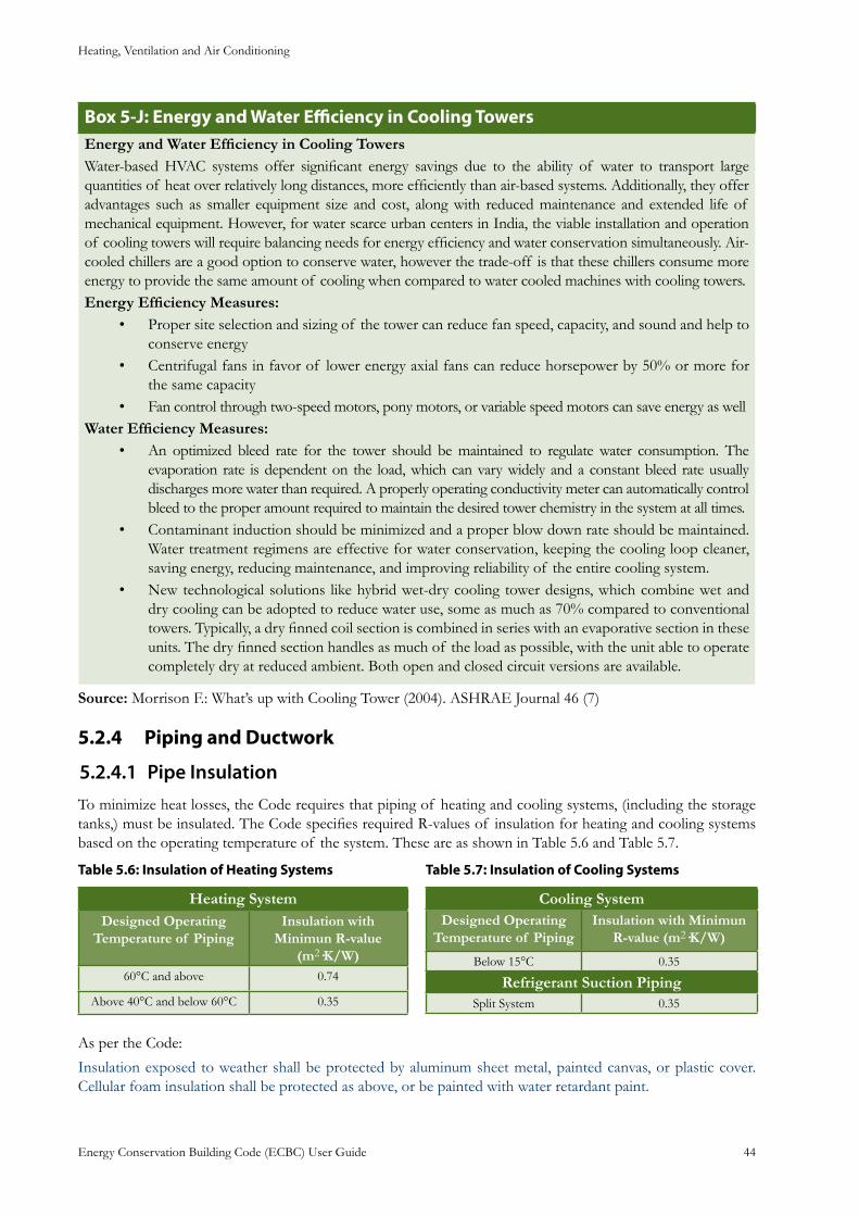
Heating, Ventilation and Air Conditioning
Energy Conservation Building Code (ECBC) User Guide 44
: Energy and Water Efficiency in Cooling TowersBox 5-JEnergy and Water Efficiency in Cooling TowersWater-based HVAC systems offer significant energy savings due to the ability of water to transport large quantities of heat over relatively long distances, more efficiently than air-based systems. Additionally, they offer advantages such as smaller equipment size and cost, along with reduced maintenance and extended life of mechanical equipment. However, for water scarce urban centers in India, the viable installation and operation of cooling towers will require balancing needs for energy efficiency and water conservation simultaneously. Air-cooled chillers are a good option to conserve water, however the trade-off is that these chillers consume more energy to provide the same amount of cooling when compared to water cooled machines with cooling towers.Energy Efficiency Measures:
Proper site selection and sizing of the tower can reduce fan speed, capacity, and sound and help to • conserve energyCentrifugal fans in favor of lower energy axial fans can reduce horsepower by 50% or more for • the same capacityFan control through two-speed motors, pony motors, or variable speed motors can save energy as well•
Water Efficiency Measures:An optimized bleed rate for the tower should be maintained to regulate water consumption. The • evaporation rate is dependent on the load, which can vary widely and a constant bleed rate usually discharges more water than required. A properly operating conductivity meter can automatically control bleed to the proper amount required to maintain the desired tower chemistry in the system at all times. Contaminant induction should be minimized and a proper blow down rate should be maintained. • Water treatment regimens are effective for water conservation, keeping the cooling loop cleaner, saving energy, reducing maintenance, and improving reliability of the entire cooling system. New technological solutions like hybrid wet-dry cooling tower designs, which combine wet and • dry cooling can be adopted to reduce water use, some as much as 70% compared to conventional towers. Typically, a dry finned coil section is combined in series with an evaporative section in these units. The dry finned section handles as much of the load as possible, with the unit able to operate completely dry at reduced ambient. Both open and closed circuit versions are available.
Source: Morrison F.: What’s up with Cooling Tower (2004). ASHRAE Journal 46 (7)
Piping and Ductwork5.2.4
Pipe Insulation5.2.4.1 To minimize heat losses, the Code requires that piping of heating and cooling systems, (including the storage tanks,) must be insulated. The Code specifies required R-values of insulation for heating and cooling systems based on the operating temperature of the system. These are as shown in Table 5.6 and Table 5.7.
: Insulation of Heating SystemsTable 5.6
Heating SystemDesigned Operating
Temperature of PipingInsulation with
Minimun R-value (m2·K/W)
60°C and above 0.74
Above 40°C and below 60°C 0.35
: Insulation of Cooling SystemsTable 5.7
Cooling SystemDesigned Operating
Temperature of PipingInsulation with Minimun
R-value (m2·K/W)
Below 15°C 0.35
Refrigerant Suction PipingSplit System 0.35
As per the Code:
Insulation exposed to weather shall be protected by aluminum sheet metal, painted canvas, or plastic cover. Cellular foam insulation shall be protected as above, or be painted with water retardant paint.
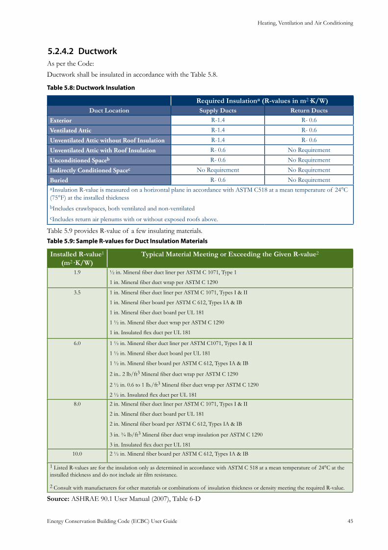
Heating, Ventilation and Air Conditioning
Energy Conservation Building Code (ECBC) User Guide 45
Ductwork5.2.4.2 As per the Code:
Ductwork shall be insulated in accordance with the Table 5.8.
: Ductwork InsulationTable 5.8
Required Insulationa (R-values in m2·K/W)Duct Location Supply Ducts Return Ducts
Exterior R-1.4 R- 0.6
Ventilated Attic R-1.4 R- 0.6
Unventilated Attic without Roof Insulation R-1.4 R- 0.6
Unventilated Attic with Roof Insulation R- 0.6 No Requirement
Unconditioned Spaceb R- 0.6 No Requirement
Indirectly Conditioned Spacec No Requirement No Requirement
Buried R- 0.6 No RequirementaInsulation R-value is measured on a horizontal plane in accordance with ASTM C518 at a mean temperature of 24°C (75°F) at the installed thicknessbIncludes crawlspaces, both ventilated and non-ventilatedcIncludes return air plenums with or without exposed roofs above.
Table 5.9 provides R-value of a few insulating materials.: Sample R-values for Duct Insulation Materials Table 5.9
Installed R-value1 (m2· K/W)
Typical Material Meeting or Exceeding the Given R-value2
1.9 ½ in. Mineral fiber duct liner per ASTM C 1071, Type 1
1 in. Mineral fiber duct wrap per ASTM C 1290
3.5 1 in. Mineral fiber duct liner per ASTM C 1071, Types I & II
1 in. Mineral fiber board per ASTM C 612, Types IA & IB
1 in. Mineral fiber duct board per UL 181
1 ½ in. Mineral fiber duct wrap per ASTM C 1290
1 in. Insulated flex duct per UL 181
6.0 1 ½ in. Mineral fiber duct liner per ASTM C1071, Types I & II
1 ½ in. Mineral fiber duct board per UL 181
1 ½ in. Mineral fiber board per ASTM C 612, Types IA & IB
2 in.. 2 lb/ft3 Mineral fiber duct wrap per ASTM C 1290
2 ½ in. 0.6 to 1 lb./ft3 Mineral fiber duct wrap per ASTM C 1290
2 ½ in. Insulated flex duct per UL 181
8.0 2 in. Mineral fiber duct liner per ASTM C 1071, Types I & II
2 in. Mineral fiber duct board per UL 181
2 in. Mineral fiber board per ASTM C 612, Types IA & IB
3 in. ¾ lb/ft3 Mineral fiber duct wrap insulation per ASTM C 1290
3 in. Insulated flex duct per UL 181
10.0 2 ½ in. Mineral fiber board per ASTM C 612, Types IA & IB
1 Listed R-values are for the insulation only as determined in accordance with ASTM C 518 at a mean temperature of 24°C at the installed thickness and do not include air film resistance.
2 Consult with manufacturers for other materials or combinations of insulation thickness or density meeting the required R-value.
Source: ASHRAE 90.1 User Manual (2007), Table 6-D
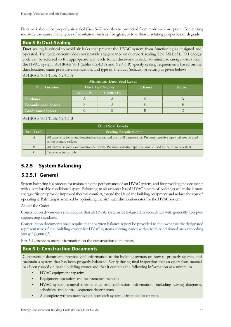
Heating, Ventilation and Air Conditioning
Energy Conservation Building Code (ECBC) User Guide 46
Ductwork should be properly air sealed (Box 5-K) and also be protected from moisture absorption. Condensing moisture can cause many types of insulation, such as fiberglass, to lose their insulating properties or degrade.
: Duct SealingBox 5-KDuct sealing is critical to avoid air leaks that prevent the HVAC system from functioning as designed and operated. The Code currently does not provide any guidance on ductwork sealing. The ASHRAE 90.1 energy code can be referred to for appropriate seal levels for all ductwork in order to minimize energy losses from the HVAC system. ASHRAE 90.1 (tables 6.2.4.3 A and 6.2.4.3 B) specify sealing requirements based on the duct location, static pressure classification, and type of the duct (exhaust or return) as given below: ASHRAE 90.1 Table 6.2.4.3 A
Minimum Duct Seal LevelDuct Location Duct Type Supply Exhaust Return
≤498.2 Pa ≥ 498.2 Pa
Outdoors A A C A
Unconditioned Spaces B A C B
Conditioned Spaces C B B C
ASHRAE 90.1 Table 6.2.4.3 B
Duct Seal LevelsSeal Level Sealing Requirements
A All transverse joints and longitudinal seams, and duct wall penetrations. Pressure-sensitive tape shall not be used as the primary sealant.
B All transverse joints and longitudinal seams. Pressure-sensitive tape shall not be used as the primary sealant
C Transverse joints only.
System Balancing5.2.5
General5.2.5.1 System balancing is a process for maintaining the performance of an HVAC system, and for providing the occupants with a comfortable conditioned space. Balancing an air or water-based HVAC system of buildings will make it more energy-efficient, provide improved thermal comfort, extend the life of the building equipment and reduce the cost of operating it. Balancing is achieved by optimizing the air/water distribution rates for the HVAC system.
As per the Code:
Construction documents shall require that all HVAC systems be balanced in accordance with generally accepted engineering standards.
Construction documents shall require that a written balance report be provided to the owner or the designated representative of the building owner for HVAC systems serving zones with a total conditioned area exceeding 500 m2 (5,000 ft2).
Box 5-L provides more information on the construction documents.
Box 5-L: Construction DocumentsConstruction documents provide vital information to the building owners on how to properly operate and maintain a system that has been properly balanced. Verify during final inspection that an operations manual has been passed on to the building owner and that it contains the following information at a minimum.
HVAC equipment capacity• Equipment operation and maintenance manuals• HVAC system control maintenance and calibration information, including wiring diagrams, • schedules, and control sequence descriptions. A complete written narrative of how each system is intended to operate.•

Heating, Ventilation and Air Conditioning
Energy Conservation Building Code (ECBC) User Guide 47
Air Systems Balancing5.2.5.1.1
Air System Balancing refers to the adjustment of airflow rates through air distribution system devices, such as fans and diffusers. This is done by adjusting the position of dampers, splitter vanes, extractors, etc., manually or by using automatic control devices, such as constant air volume or variable air volume boxes.
Balancing is necessary to verify that each space served by a system receives the air volume designed for that space. Proper means for air balancing should be installed at each supply air outlet and zone terminal device. These include balancing dampers or other means of supply-air adjustment provided in the branch ducts or at each individual duct register, grille, or diffuser. Installation in the duct system of all devices used for balancing, shown on the approved mechanical plans, typically, on the ductwork layout, should be verified.
As per the Code:
Air systems shall be balanced in a manner to minimize throttling losses. Then, for fans greater than 0.75 KW (1.0 HP), fans must then be adjusted to meet design flow conditions.
Box 5-M provides the concepts related to air handling units for air distribution systems for energy efficiency.
: Air Handling Unit ConceptsBox 5-MAn air handler is responsible for moving air throughout the duct work in an air conditioning system. All air handlers contain a blower motor and squirrel cage blower housing which facilitates the movement of air. Most air handlers also include system controls, which are connected to the thermostat. Depending on the type of system, an air handler can also be integrated with a gas, oil, electric furnace, heat pump, and cooling coils (or evaporator coil for the air conditioning).
High-efficiency air distribution systems can substantially reduce fan power required by an HVAC system, resulting in dramatic energy savings. The largest gains in efficiency for air distribution systems are realized in the system design phase for new constructions or major retrofit projects. Passive or natural air transport systems have the highest efficiency, and successful, modern examples of this approach are steadily accumulating. For buildings that require mechanical ventilation, innovative design approaches and a methodical examination of the entire air system can greatly improve efficiency and effectiveness. Air-handling efficiency The energy required to move air is calculated as follows:(Flow X Static Pressure) /EfficiencyAll these factors can be manipulated to reduce the energy consumption of the system. Air flow has a dominant effect on energy consumption because it shows up twice in the energy equation: as the first term and as a squared function in the second term (pressure). The pressure a fan must work against depends on two primary factors: the flow and duct design features such as diameter, length, surface treatment, and impediments such as elbows, filters, and coils. Typical pressure losses are on the order of 2 to 6 inches water gauge (wg); an efficient system operates at less than 1.5” wg. A fan’s duty factor is the number of hours per year that it operates, sometimes presented as a percentage. Many large fans spin at full speed continuously (8,760 hours per year). Using simple or complex controls, duty factors can often be reduced to about 3,000 hours per year or less by limiting fan operation to occupied periods. The mechanical efficiency of the fan and its drive system can typically be raised from the 40 to 60% range to the mid-80% range. Wire to air efficiency will need to be considered and is function of motor efficiency x mechanical efficiencyDesign options for improving air distribution efficiency include:
Variable-air-volume systems • VAV diffusers• Low-pressure-drop duct design• Low-face-velocity air handlers • Fan sizing and variable-frequency-drive motors• Displacement ventilation systems.•
Hydronic Systems Balancing5.2.5.1.2
Hydronic System Balancing refers to the adjustment of water flow rates through distribution system devices,
Heating, Ventilation and Air Conditioning
Energy Conservation Building Code (ECBC) User Guide 48
such as pumps and coils, by manually adjusting the position of valves, or by using automatic control devices, such as flow control valves.
When something is balanced, it is even on both sides. Therefore, a balanced hydronic system is one that delivers even flow to all of the devices on that piping system. Each component has an effective equal length of pipe on the supply and return. And when a system is balanced, all of the pressure drops are correct for the devices. When that happens, the highest efficiencies are possible in the system. One need not have to change system supply temperatures to accommodate one zone only. The system has the least amount of pressure drop possible, which translates into reduced pumping costs. A balanced hydronic system is one that is efficient. If a system that is not delivering the water to the right devices in the right amounts, then the system is out of balance.
As per the Code:
Hydronic systems shall be proportionately balanced in a manner to first minimize throttling losses; then the pump impeller shall be trimmed or pump speed shall be adjusted to meet design flow conditions.
Exceptions to above:
Impellers need not be trimmed nor pump speed adjusted for pumps with pump motors of 7.5 kW a. (10 hp) or less,
Impellers need not be trimmed when throttling results in no greater than 5% of the nameplate b. horsepower draw, or 2.2 kW (3 hp), whichever is greater.
Condensers5.2.6
Condenser Locations5.2.6.1 A condenser is a heat exchanger that liquefies refrigerant vapor through heat removal. The typical condensing unit houses a compressor, a condenser fan motor, and coils, along with controls which make all the components work sequentially.
As per the Code:
Care shall be exercised in locating the condensers in such a manner that the heat sink is free of interference from heat discharge by devices located in adjoining spaces and also does not interfere with such other systems installed nearby.
Condensers should be located in such a manner that there is no restriction to the air flow around the condenser coils, there is no short-circuiting of discharge air to the intake side, and the heat discharge of other adjacent equipment is not anywhere the air intake of the condenser.
Treated Water for Condensers5.2.6.2 Condenser water treatment is important to eliminate mineral buildup in condensers and chilled water systems. Mineral deposits create poor heat transfer situations there by reducing the efficiency of the unit.
As per the Code:
All high-rise buildings using centralized cooling water system shall use soft water for the condenser and chilled water system.
Prescriptive Requirements5.3 As per the Code:
The prescriptive requirements apply only if the HVAC system in the building meets the following criteria:
Serves a single zonea.
Cooling (if any) is provided by a unitary packaged or split-system air conditioner or heat pumpb.
Heating (if any) is provided by a unitary packaged or split-system heat pump, fuel-fired furnace, c. electric resistance heater, or baseboards connected to a boiler
Outside air quantity is less than 1,400 l/s (3,000 cfm) and less than 70% of supply air at design d. conditions
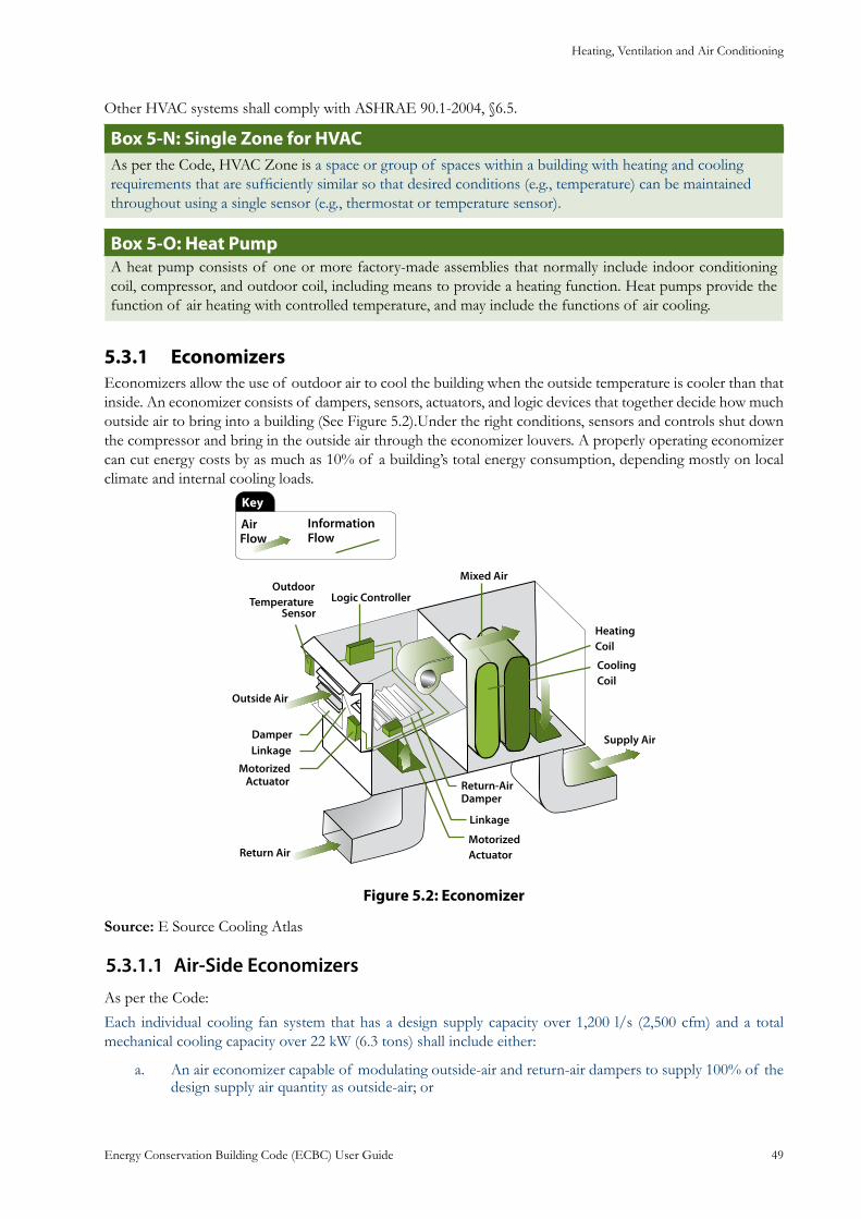
Heating, Ventilation and Air Conditioning
Energy Conservation Building Code (ECBC) User Guide 49
Other HVAC systems shall comply with ASHRAE 90.1-2004, §6.5.
: Single Zone for HVACBox 5-NAs per the Code, HVAC Zone is a space or group of spaces within a building with heating and cooling requirements that are sufficiently similar so that desired conditions (e.g., temperature) can be maintained throughout using a single sensor (e.g., thermostat or temperature sensor).
: Heat Pump Box 5-OA heat pump consists of one or more factory-made assemblies that normally include indoor conditioning coil, compressor, and outdoor coil, including means to provide a heating function. Heat pumps provide the function of air heating with controlled temperature, and may include the functions of air cooling.
Economizers5.3.1 Economizers allow the use of outdoor air to cool the building when the outside temperature is cooler than that inside. An economizer consists of dampers, sensors, actuators, and logic devices that together decide how much outside air to bring into a building (See Figure 5.2).Under the right conditions, sensors and controls shut down the compressor and bring in the outside air through the economizer louvers. A properly operating economizer can cut energy costs by as much as 10% of a building’s total energy consumption, depending mostly on local climate and internal cooling loads.
: EconomizerFigure 5.2
Source: E Source Cooling Atlas
Air-Side Economizers5.3.1.1 As per the Code:
Each individual cooling fan system that has a design supply capacity over 1,200 l/s (2,500 cfm) and a total mechanical cooling capacity over 22 kW (6.3 tons) shall include either:
An air economizer capable of modulating outside-air and return-air dampers to supply 100% of the a. design supply air quantity as outside-air; or
Heating, Ventilation and Air Conditioning
Energy Conservation Building Code (ECBC) User Guide 50
A water economizer capable of providing 100% of the expected system cooling load at outside air b. temperatures of 10°C (50°F) dry-bulb/7.2°C (45°F) wet-bulb and below
Exceptions to above are:
Projects in the hot-dry and warm-humid climate zones are exempta.
Individual ceiling mounted fan systems < 3,200 l/s (6,500 cfm) are exemptb.
: EconomizersBox 5-PAir EconomizerAn air economizer is duct and damper arrangement and automatic control system that together allow a cooling system to supply outdoor air to reduce or eliminate the need for mechanical cooling during mild or cold weather.Water EconomizerA water economizer is a system by which the supply air of a cooling system is cooled indirectly with water that is itself cooled by heat or mass transfer to the environment without the use of mechanical cooling.
Partial Cooling5.3.1.2 One can use the building’s intrinsic thermal mass to reduce peak cooling loads by circulating cool night-time air to pre-cool the building prior to daily occupancy in the cooling season. The building control system can operate ventilation fans in the economizer mode on a scheduled basis. Care should be taken to prevent excessive fan operation that would offset cooling energy savings. It is also ensured that night humidity does not preclude the use of this strategy.
As per the Code:
Economizers shall be capable of providing partial cooling even when additional mechanical cooling is required to meet the cooling load.
Testing of Air-Side Economizer5.3.1.3 As per the Code:
Air-side economizers shall be tested in the field following the requirements in Appendix F (of the Code) to ensure proper operation.
Exception to above:
Air economizers installed by the HVAC system equipment manufacturer and certified to the building department as being factory calibrated and tested per the procedures in Appendix F (of the Code).
Variable Flow Hydronic Systems5.3.2 Fluid from the heating or cooling source is supplied to heat transfer devices, such as coils and heat exchangers, and back through the hydronic system. The Code specifies the type of equipment and capabilities in such a way as to reduce pump energy. Variable fluid flow, automatic isolation valves, and variable speed drives enable the system to operate below design flow when needed.
Variable Fluid Flow in Chilled or Hot Water System5.3.2.1 As per the Code:
Chilled or hot-water systems shall be designed for variable fluid flow and shall be capable of reducing pump flow rates to no more than the larger of:
50% of the design flow rate, ora.
The minimum flow required by the equipment manufacturer for proper operation of the chillers or b. boilers.

Heating, Ventilation and Air Conditioning
Energy Conservation Building Code (ECBC) User Guide 51
Automatic Isolation Valves5.3.2.2 Two-way automatic isolation valves serve as a means of varying flow rate in a hydronic system.
As per the Code:
Water cooled air-conditioning or heat pump units with a circulation pump motor greater than or equal to 3.7 kW (5 hp) shall have two-way automatic isolation valves on each water cooled air-conditioning or heat pump unit that are interlocked with the compressor to shut off condenser water flow when the compressor is not operating.
Variable Speed Drives5.3.2.3 Variable speed drives are required to control chilled water and condenser water systems for energy efficiency.
As per the Code:
Chilled water or condenser water systems that must comply with either §5.3.2.1 or §5.3.2.2 (of ECBC) and that have pump motors greater than or equal to 3.7 kW (5 hp) shall be controlled by variable speed drives.
Service Water Heating and Pumping
Energy Conservation Building Code (ECBC) User Guide 52
Service Water Heating and Pumping6. General6.1
For some building types such as large hotels and hospitals service water heating can be major energy con-sumer. Inefficiency in water heating is caused primarily by inefficiency of the heating equipment, and by
heat loss from hot water storage tanks and distribution piping network.
ECBC through mandatory requirements seeks to minimize energy usage in water heating systems by: Utilizing solar water heating• Specifying heating equipment efficiency • Maximizing heat recovery and minimizing electric heating• Insulating hot water storage tanks and pipelines• Reducing standby losses• Reducing heat and evaporation losses in heated swimming pools•
Mandatory Requirements6.2 Solar Water Heating6.2.1
As per the Code:
Residential facilities, hotels and hospitals with a centralized system shall have solar water heating for at least 1/5 of the design capacity.
Exception to above:
Systems that use heat recovery for at least 1/5 of the design capacity.
There are two types of solar water heaters. Passive heaters collect and store solar thermal energy for water heating applications and do not require electrical energy input for recirculating water through solar collector. Active heaters collect and store solar thermal energy for water heating applications and require electrical energy input for operation of recirculation pumps or other components. Figure 6.1 and Figure 6.2 show examples of solar water heating systems.
An exception is provided by the Code for systems that use heat recovery systems for at least one-fifth (20%) of the design capacity. For example heat is rejected from the air conditioner’s condenser to the atmosphere. By recovering this waste heat and utilizing it to heat water, wherever feasible, it is possible to substantially reduce water-heating costs.
Box 6-A provides information on various water heating systems normally used in practice.
: Types of Water HeatersBox 6-AStorage Gas: A gas water heater designed to heat and store water at less than 80°C. Water temperature is controlled with a thermostat. Storage Electric: An electric water heater designed to heat and store water at less than 80°C. Water tem-perature is controlled with a thermostat. Storage electric water heaters have a manufacturer’s specified capac-ity of at least two gallons.Storage Heat Pump: An electric water heater that uses a compressor to transfer thermal energy from one temperature level to a higher temperature level for the purpose of heating water. It includes all necessary auxiliary equipment such as fans, storage tanks, pumps or controls. Instantaneous Gas: A gas water heater controlled manually or automatically by water flow activated control or a combination of water flow and thermostatic controls.
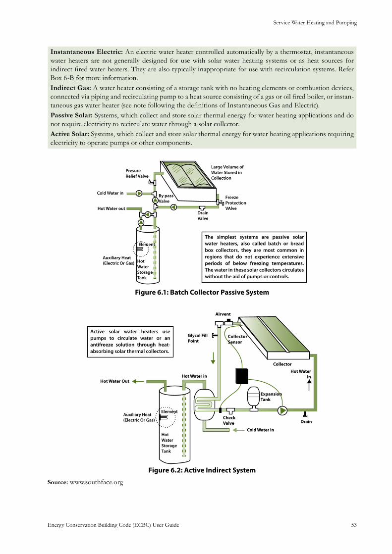
Service Water Heating and Pumping
Energy Conservation Building Code (ECBC) User Guide 53
Instantaneous Electric: An electric water heater controlled automatically by a thermostat, instantaneous water heaters are not generally designed for use with solar water heating systems or as heat sources for indirect fired water heaters. They are also typically inappropriate for use with recirculation systems. Refer Box 6-B for more information.Indirect Gas: A water heater consisting of a storage tank with no heating elements or combustion devices, connected via piping and recirculating pump to a heat source consisting of a gas or oil fired boiler, or instan-taneous gas water heater (see note following the definitions of Instantaneous Gas and Electric).Passive Solar: Systems, which collect and store solar thermal energy for water heating applications and do not require electricity to recirculate water through a solar collector.Active Solar: Systems, which collect and store solar thermal energy for water heating applications requiring electricity to operate pumps or other components.
The simplest systems are passive solar water heaters, also called batch or bread box collectors, they are most common in regions that do not experience extensive periods of below freezing temperatures. The water in these solar collectors circulates without the aid of pumps or controls.
: Batch Collector Passive SystemFigure 6.1
Active solar water heaters use pumps to circulate water or an antifreeze solution through heat-absorbing solar thermal collectors.
: Active Indirect SystemFigure 6.2
Source: www.southface.org
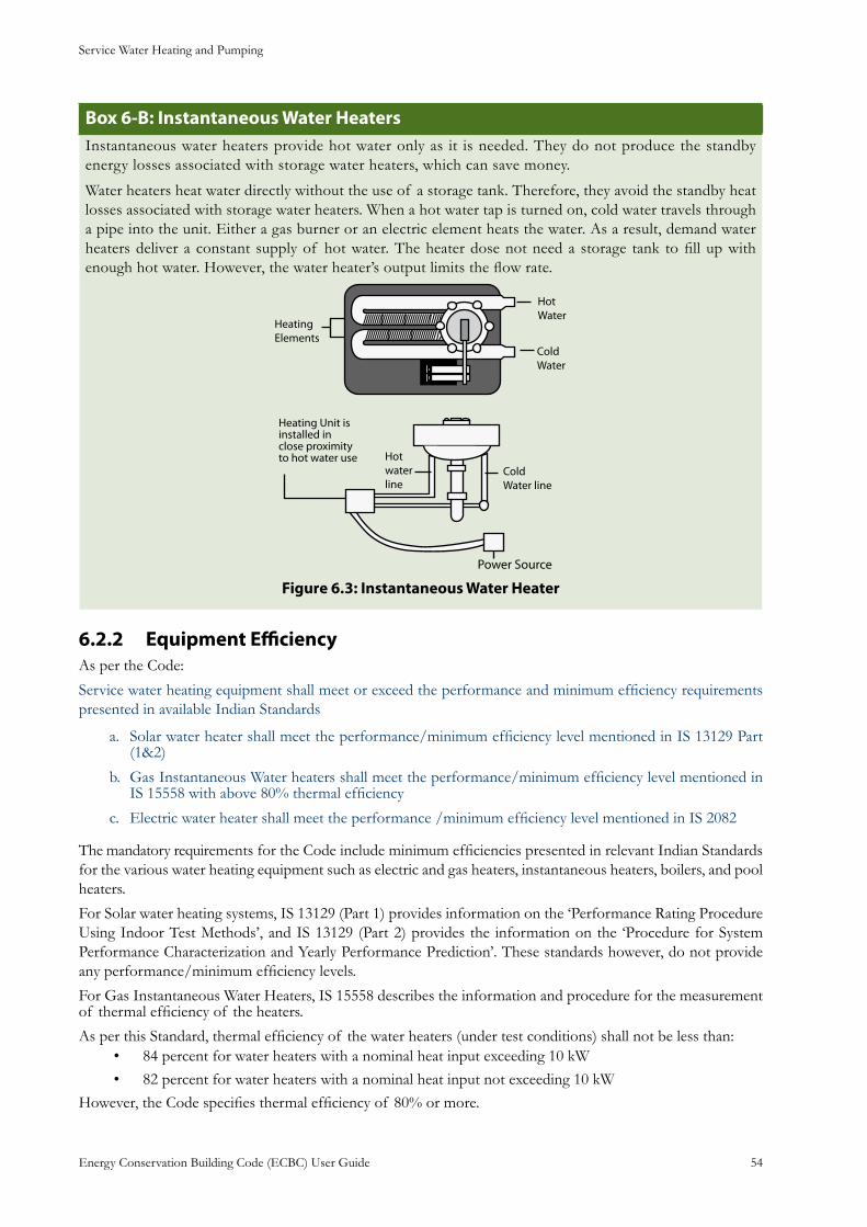
Service Water Heating and Pumping
Energy Conservation Building Code (ECBC) User Guide 54
: Instantaneous Water HeatersBox 6-BInstantaneous water heaters provide hot water only as it is needed. They do not produce the standby energy losses associated with storage water heaters, which can save money.
Water heaters heat water directly without the use of a storage tank. Therefore, they avoid the standby heat losses associated with storage water heaters. When a hot water tap is turned on, cold water travels through a pipe into the unit. Either a gas burner or an electric element heats the water. As a result, demand water heaters deliver a constant supply of hot water. The heater dose not need a storage tank to fill up with enough hot water. However, the water heater’s output limits the flow rate.
: Instantaneous Water HeaterFigure 6.3
Equipment Efficiency6.2.2 As per the Code:
Service water heating equipment shall meet or exceed the performance and minimum efficiency requirements presented in available Indian Standards
Solar water heater shall meet the performance/minimum efficiency level mentioned in IS 13129 Part a. (1&2)
Gas Instantaneous Water heaters shall meet the performance/minimum efficiency level mentioned in b. IS 15558 with above 80% thermal efficiency
Electric water heater shall meet the performance /minimum efficiency level mentioned in IS 2082c.
The mandatory requirements for the Code include minimum efficiencies presented in relevant Indian Standards for the various water heating equipment such as electric and gas heaters, instantaneous heaters, boilers, and pool heaters.
For Solar water heating systems, IS 13129 (Part 1) provides information on the ‘Performance Rating Procedure Using Indoor Test Methods’, and IS 13129 (Part 2) provides the information on the ‘Procedure for System Performance Characterization and Yearly Performance Prediction’. These standards however, do not provide any performance/minimum efficiency levels.
For Gas Instantaneous Water Heaters, IS 15558 describes the information and procedure for the measurement of thermal efficiency of the heaters.
As per this Standard, thermal efficiency of the water heaters (under test conditions) shall not be less than: 84 percent for water heaters with a nominal heat input exceeding 10 kW• 82 percent for water heaters with a nominal heat input not exceeding 10 kW•
However, the Code specifies thermal efficiency of 80% or more.
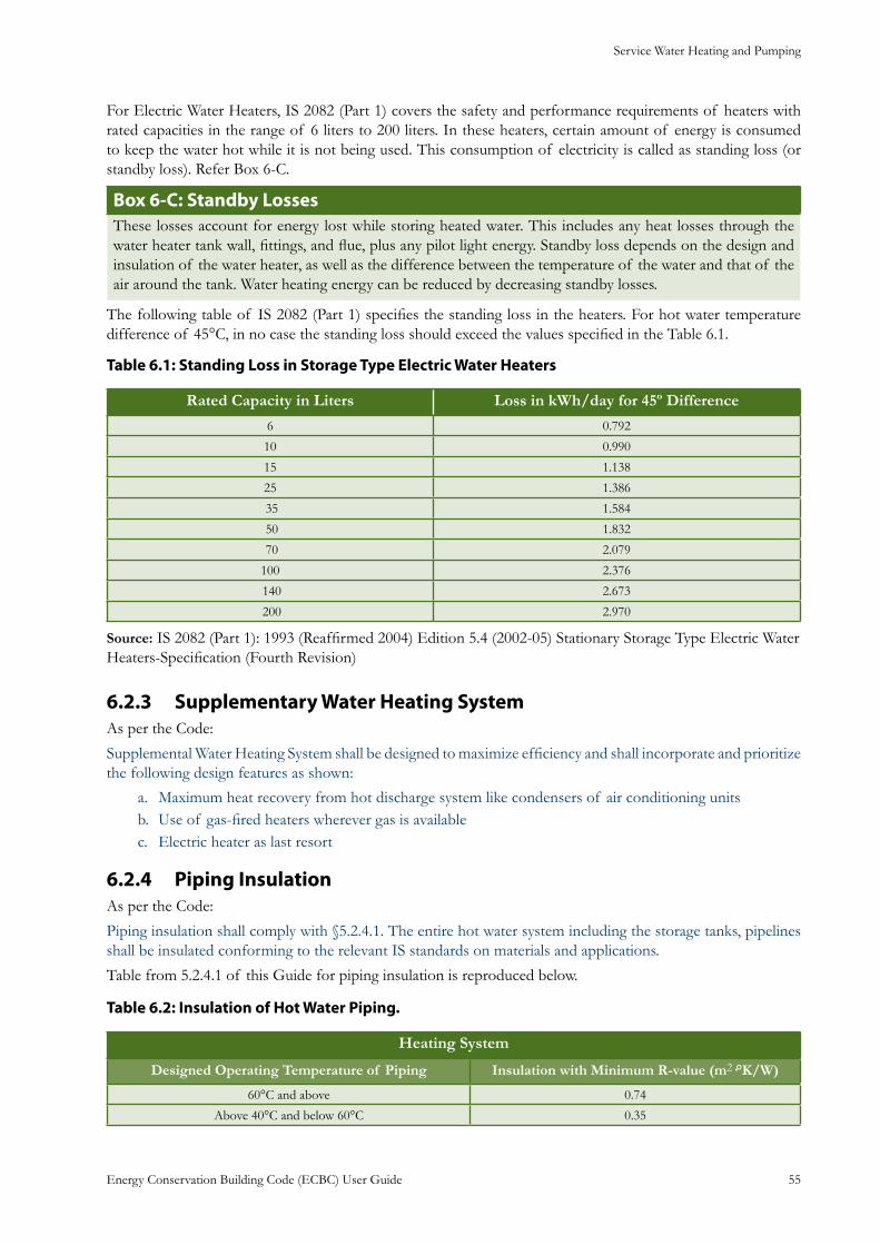
Service Water Heating and Pumping
Energy Conservation Building Code (ECBC) User Guide 55
For Electric Water Heaters, IS 2082 (Part 1) covers the safety and performance requirements of heaters with rated capacities in the range of 6 liters to 200 liters. In these heaters, certain amount of energy is consumed to keep the water hot while it is not being used. This consumption of electricity is called as standing loss (or standby loss). Refer Box 6-C.
: Standby Losses Box 6-CThese losses account for energy lost while storing heated water. This includes any heat losses through the water heater tank wall, fittings, and flue, plus any pilot light energy. Standby loss depends on the design and insulation of the water heater, as well as the difference between the temperature of the water and that of the air around the tank. Water heating energy can be reduced by decreasing standby losses.
The following table of IS 2082 (Part 1) specifies the standing loss in the heaters. For hot water temperature difference of 45°C, in no case the standing loss should exceed the values specified in the Table 6.1.
: Standing Loss in Storage Type Electric Water HeatersTable 6.1
Rated Capacity in Liters Loss in kWh/day for 45º Difference
6 0.792
10 0.990
15 1.138
25 1.386
35 1.584
50 1.832
70 2.079
100 2.376
140 2.673
200 2.970
Source: IS 2082 (Part 1): 1993 (Reaffirmed 2004) Edition 5.4 (2002-05) Stationary Storage Type Electric Water Heaters-Specification (Fourth Revision)
Supplementary Water Heating System6.2.3 As per the Code:
Supplemental Water Heating System shall be designed to maximize efficiency and shall incorporate and prioritize the following design features as shown:
Maximum heat recovery from hot discharge system like condensers of air conditioning unitsa. Use of gas-fired heaters wherever gas is availableb. Electric heater as last resortc.
Piping Insulation6.2.4 As per the Code:
Piping insulation shall comply with §5.2.4.1. The entire hot water system including the storage tanks, pipelines shall be insulated conforming to the relevant IS standards on materials and applications.
Table from 5.2.4.1 of this Guide for piping insulation is reproduced below.
: Insulation of Hot Water Piping.Table 6.2
Heating System
Designed Operating Temperature of Piping Insulation with Minimum R-value (m2·°K/W)
60°C and above 0.74
Above 40°C and below 60°C 0.35
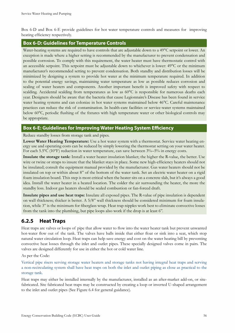
Service Water Heating and Pumping
Energy Conservation Building Code (ECBC) User Guide 56
Box 6-D and Box 6-E provide guidelines for hot water temperature controls and measures for improving heating efficiency respectively.
: Guidelines for Temperature ControlsBox 6-DWater-heating systems are required to have controls that are adjustable down to a 49°C setpoint or lower. An exception is made where a higher setting is recommended by the manufacturer to prevent condensation and possible corrosion. To comply with this requirement, the water heater must have thermostatic control with an accessible setpoint. This setpoint must be adjustable down to whichever is lower: 49°C or the minimum manufacturer’s recommended setting to prevent condensation. Both standby and distribution losses will be minimized by designing a system to provide hot water at the minimum temperature required. In addition to the potential energy savings, maintaining water temperature as low as possible reduces corrosion and scaling of water heaters and components. Another important benefit is improved safety with respect to scalding. Accidental scalding from temperatures as low as 60°C is responsible for numerous deaths each year. Designers should be aware that the bacteria that cause Legionnaire’s Disease has been found in service water heating systems and can colonize in hot water systems maintained below 46°C. Careful maintenance practices can reduce the risk of contamination. In health-care facilities or service-water systems maintained below 60°C, periodic flushing of the fixtures with high temperature water or other biological controls may be appropriate.
: Guidelines for Improving Water Heating System EfficiencyBox 6-EReduce standby losses from storage tank and pipes.Lower Water Heating Temperature: Use a hot water system with a thermostat. Service water heating en-ergy use and operating costs can be reduced by simply lowering the thermostat setting on your water heater. For each 5.5ºC (10ºF) reduction in water temperature, can save between 3%–5% in energy costs.Insulate the storage tank: Install a water heater insulation blanket; the higher the R-value, the better. Use wire or twine or straps to insure that the blanket stays in place. Some new high-efficiency heaters should not be insulated; consult the equipment manual provided by the manufacturer. Gas water heaters should not be insulated on top or within about 8” of the bottom of the water tank. Set an electric water heater on a rigid foam insulation board. This step is most critical when the heater sits on a concrete slab, but it’s always a good idea. Install the water heater in a heated location. The colder the air surrounding the heater, the more the standby loss. Indoor gas heaters should be sealed combustion or fan-forced draft.
Insulate pipes and use heat traps: Insulate all exposed pipes. The R-value of pipe insulation is dependent on wall thickness; thicker is better. A 5/8” wall thickness should be considered minimum for foam insula-tion, while 3” is the minimum for fiberglass wrap. Heat trap nipples work best to eliminate convective losses from the tank into the plumbing, but pipe loops also work if the drop is at least 6”.
Heat Traps6.2.5 Heat traps are valves or loops of pipe that allow water to flow into the water heater tank but prevent unwanted hot-water flow out of the tank. The valves have balls inside that either float or sink into a seat, which stop natural water circulation loop. Heat traps can help save energy and cost on the water heating bill by preventing convective heat losses through the inlet and outlet pipes. These specially designed valves come in pairs. The valves are designed differently for use in either the hot or cold water line.
As per the Code:
Vertical pipe risers serving storage water heaters and storage tanks not having integral heat traps and serving a non-recirculating system shall have heat traps on both the inlet and outlet piping as close as practical to the storage tank.
Heat traps may either be installed internally by the manufacturer, installed as an after-market add-on, or site-fabricated. Site fabricated heat traps may be constructed by creating a loop or inverted U-shaped arrangement to the inlet and outlet pipes (See Figure 6.4 for general guidance).
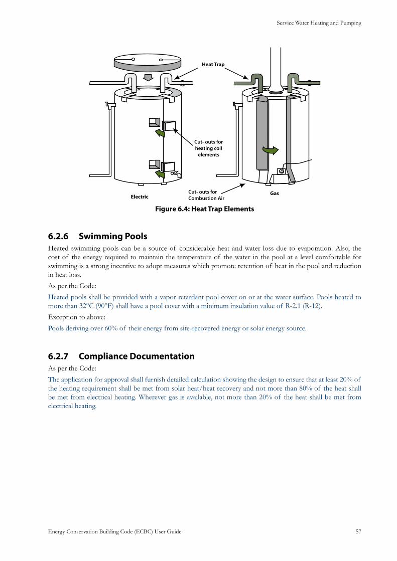
Service Water Heating and Pumping
Energy Conservation Building Code (ECBC) User Guide 57
: Heat Trap ElementsFigure 6.4
Swimming Pools6.2.6 Heated swimming pools can be a source of considerable heat and water loss due to evaporation. Also, the cost of the energy required to maintain the temperature of the water in the pool at a level comfortable for swimming is a strong incentive to adopt measures which promote retention of heat in the pool and reduction in heat loss.
As per the Code:
Heated pools shall be provided with a vapor retardant pool cover on or at the water surface. Pools heated to more than 32°C (90°F) shall have a pool cover with a minimum insulation value of R-2.1 (R-12).
Exception to above:
Pools deriving over 60% of their energy from site-recovered energy or solar energy source.
Compliance Documentation6.2.7 As per the Code:
The application for approval shall furnish detailed calculation showing the design to ensure that at least 20% of the heating requirement shall be met from solar heat/heat recovery and not more than 80% of the heat shall be met from electrical heating. Wherever gas is available, not more than 20% of the heat shall be met from electrical heating.
Lighting
Energy Conservation Building Code (ECBC) User Guide 58
Lighting7.
General7.1
Lighting accounts for 15% of total energy consumption in India. Lighting is an area that offers many energy efficiency opportunities in almost any building facility, existing or new.
A century ago, a person could read by the light of a single candle, but today a person in a typical office uses hundreds or even thousand times more light. Over the years, illumination standards have increased radically along with efficiency of lamps.
People want light for different reasons, and a good lighting designer need to keep all of them in mind. Different tasks and building facilities require different amounts and types of light. For example, a surgeon in an operation theater needs lots of light with low glare and excellent color rendering, restaurant owners and diners often want low light levels, corporate boardrooms call for lighting that reinforces a feeling of importance and success while adapting to audio-visual presentations; retail outlets in many situations want to make their merchandise sparkle so that it draws the customers and encourages them to buy. An office executive needs modest ambient lighting level, good task lighting on work surface, and minimal glare to effectively read and work on computers.
While energy efficiency is an attractive goal for many reasons, lighting designers also need to consider a host of other factors, including the effect of quality of light on the visual comfort and productivity of the occupants. Small improvement in lighting quality can improve productivity of the user substantially. In practice, the right quality and quantity of light can be provided efficiently (with less energy) by using the right technology and its effective integration with daylight.
General Design Considerations
Using efficient lighting equipment and controls is the best way to ensure lighting energy efficiency while maintaining or even improving lighting conditions. For instance, modern fluorescent lighting, such as electronically ballasted T-8 systems, can provide the same quantity of light as older fluorescent lighting while consuming as little as two-thirds of the energy. Similarly, compact fluorescent sources are three to four times more efficient than the traditional incandescent lamps they are designed to replace.
For a lighting designer an energy-efficient lighting design involves sensitive integration of many requirements and considerations that include building orientation, interior building layout, task illumination, daylight strategies, glazing specification, choice of lighting system and controls etc. The designer is also responsible for making sure that lighting complies with the Code, meeting both mandatory and prescriptive requirements.
The lighting requirements in the Code apply to:
Interior spaces of buildingsa.
Exterior building features, including façades, illuminated roofs, architectural features, entrances, exits, b. loading docks, and illuminated canopies
Exterior building grounds lighting that is provided through the building’s electrical service c. Exceptions to above:
Emergency lighting that is automatically off during normal building operation and is powered by a. battery, generator, or other alternate power source
Lighting in dwelling units b.
Mandatory Requirements7.2 The mandatory requirements for lighting mostly relate to interior and exterior lighting controls.
Lighting
Energy Conservation Building Code (ECBC) User Guide 59
Lighting Control7.2.1
Lighting controls allow lighting to be turned down or completely off when it is not needed – the simplest way to save energy. Maximizing the use of controls involves developing a set of strategies that utilize the Code requirements for various devices, including on-off controls, dimming controls, and systems that combine the use of both types of equipment. These controls can be quite sophisticated, but in general, they perform two basic functions:1) they turn lights off when not needed, and 2) they modulate light output so that no more light than necessary is produced. The equipment required to achieve these functions varies in complexity from simple timers to intricate electronic dimming circuits, each applicable to different situations. Controls include time clocks, occupant and motion sensors, automatic or manual daylighting controls, and astronomical time switches (the automatic switches that adjust for the length of the day as it varies over the year).
: Manual Vs. Automatic ControlsBox 7-AManual lighting controls range from a single switch to a bank of switches and dimmers that are actuated by toggles, rotary knobs, push buttons, remote control, and other means. Manual controls can be cost-effective options for small-scale situations. However, as the lighting system becomes larger, automated systems become more cost-effective and are better at controlling light. Manual controls may not give the desired results in real situations because the decision to shut off the lights when they are not needed is based entirely on human initiative. It is worthwhile to determine the amount of local vs. central control that is needed from the lighting control system.
Automatic Lighting Shutoff7.2.1.1 Although there is no simpler way to reduce the amount of energy consumed by lighting systems than to manually turn lights off whenever not needed, this is not done as often as it could be. In response to that problem, the Code requires several automatic switches that either work on time schedule or sense the presence of occupants.
Automatic Control Strategies
Several different approaches can be used to control electric lighting. The control hardware and design practices are discussed below:
Scheduling Control:• Use a time scheduling device to control lighting systems according to predetermined schedules.Occupancy Sensing:• Control lights in response to the presence or absence of people in the space.
Daylighting:• Switch or dim electric lights in response to the presence or absence of daylight illumination in the space.
Lumen Maintenance:• Gradually adjust electric light levels over time to correspond with the depreciation of light output from aging lamps.
As per the Code:
Interior lighting systems in buildings larger than 500 m2 (5,000 ft²) shall be equipped with an automatic control device. Within these buildings, all office areas less than 30 m2 (300 ft2) enclosed by walls or ceiling-height partitions, all meeting and conference rooms, all school classrooms, and all storage spaces shall be equipped with occupancy sensors. For other spaces, this automatic control device shall function on either
A scheduled basis at specific programmed times. An independent program schedule shall be provided a. for areas of no more than 2,500 m2 (25,000 ft²) and not more than one floor; or,
Occupancy sensors that shall turn the lighting off within 30 minutes of an occupant leaving the b. space. Light fixtures controlled by occupancy sensors shall have a wall-mounted, manual switch capable of turning off lights when the space is occupied.
Exception to above:
Lighting systems designed for 24-hour use.
Lighting
Energy Conservation Building Code (ECBC) User Guide 60
Box 7-B provides a brief on scheduling controls.
Box 7-B: Scheduling ControlsProgrammable timing, also known as automatic time scheduling, is the oldest form of automatic lighting control. Time scheduling manages the on and off times of a building’s lighting systems.Scheduling systems function by turning off all or some of the lights when a building space is unoccupied. In the most basic time-scheduling scheme, a time switch switches lighting circuits on or off based on programmable schedules. For example, exterior lighting is usually switched on to correspond to sundown and is switched off again at daybreak. By contrast, time scheduling of interior lighting systems is based, for the most part, on occupancy schedules. In some cases, time switches are used to energize additional lighting control systems, such as daylighting controls, which are held off during unoccupied periods. Time-scheduling systems employ the following components:
A central processor is usually capable of controlling several output channels, each of which may • be assigned to one or more lighting circuits.Relays are series-wired to lighting control zones and are controlled by the central processor.• Overrides are required to accommodate individuals who use the space during scheduled off • hours. Individuals can activate manual switches or use telephone overrides to regain temporary control of the lights in a given space.
Occupant-sensing devices are an alternative to scheduling controls and an acceptable means of meeting the requirement for automatic shutoff. The designer is free to arrange occupant sensing controls in any manner that makes sense for the building design. In office spaces, each room or space might have an occupant sensor. Of course, the smaller the area controlled, the greater the energy savings will be. In open office areas, several occupant sensors may be connected so that the lights remain on if any one of the sensors detects occupants.
However, in order to satisfy the requirement, it is necessary that all the general lighting be controlled by one or more occupant sensors.
Box 7-C provides more information on occupancy sensors.
Box 7-C: Occupancy SensorsOccupancy sensors are automatic scheduling devices that detect motion and turn lights on and off accordingly. Most devices can be calibrated for sensitivity and for the length-of-time delay between the last detected occupancy and extinguishing of the lights. The most energy-efficient occupancy sensors, known as “manual-on, automatic-off,” require that the user manually switch on the lights when entering a controlled zone (the “lights off ” function is still automatic).
Occupancy sensor systems typically consist of a motion detector, a control unit, and a relay. Usually, two or more of the components are integrated into one package. Most systems also require a power supply in the form of a transformer, which steps down the building voltage to 24V. The detector collects information, then sends it to the controller, where it is processed. Output from the controller activates the relay, which in turn switches the light circuit.There are two major types of occupancy controls.
Wallbox • units are designed to fit into a standard wall switch box and operate on the building volt-age (i.e., a separate power supply is not required). They are excellent, inexpensive replacements for standard wall switches. Their main limitation is their relatively short range. Consequently, they tend to be used in small offices and meeting rooms.
Wall and Ceiling • units typically contain an integrated sensor/controller unit wired (Class 2) to a switch pack containing the relay and power supply. They are far more popular than wallbox units and have very few application limitations.
Lighting
Energy Conservation Building Code (ECBC) User Guide 61
Occupancy-sensing lighting controls represent a refinement of the technology developed in the early 1970s to detect intruders for residential and commercial security applications. With lighting control, two different means of detecting occupancy are used:
Passive Infrared (PIR) sensors• perceive and respond to the heat patterns of motion. This same technology is used in most residential and commercial security systems. The chief advantage of PIR sensors is that they are relatively inexpensive and reliable. They very rarely “false trigger” (that is, respond to non occupant motion in a space). The major limitation of PIR sensors is that they are strictly line-of-sight devices, unable to see around corners or partitions.
Ultrasound (US) detectors• radiate ultrasonic waves into a space, then read the frequency of the re-flected waves. Motion causes a slight shift in frequency, which the detector interprets as occupancy. They are more sensitive than PIR sensors, which is both an advantage and a disadvantage. They are often used very effectively in partitioned spaces but are also more prone to false triggering due to their sensitivity to air movement. Proper design and installation minimizes this potential problem.
Space Control7.2.1.2 Along with controls for individual lights or sets of fixtures, master controls are required for each space which can shut off all the lights within the space. For example, the last person leaving the office is much more likely to use a master switch than to go through the office turning off every switch. Similarly, a cleaning crew can easily use master switches to turn lights off at the end of a working day.
As per Code:
Each space enclosed by ceiling-height partitions is required to have at least one control device to independently control the lighting within the space. The device can be a switch that is activated either manually or automatically by sensing an occupant sensor. Each control device, regardless of type, shall have the following functions:
Control a maximum of 250 ma. 2 (2,500 ft2) for a space less than or equal to 1,000 m2 (10,000 ft2), and a maximum of 1,000 m2 (10,000 ft2) for a space greater than 1,000 m2 (10,000 ft2)
Be capable of overriding the required shutoff control [ECBC 7.2.1.1] for no more than 2 hoursb.
Be readily accessible and located so the occupant can see the control.c.
Box 7-D summarizes the Code requirements.
: Space Area and Lighting ControlsBox 7-DS.No. Space Area Coverage Area for each control device
1 Up to 1000 m2 250 m2 max.
2 More than 1000 m2 1000 m2 max.
Exception to (c) above:
The required control device may be remotely installed if required for reasons of safety or security. A remotely located device shall have a pilot light indicator as part of or next to the control device and shall be clearly labeled to identify the controlled lighting.
An exception to (c) is provided for control devices that need to be remotely installed for reasons of safety or security. However, a remotely located device must have a pilot light indicator as part of or next to the control device and it must be clearly labeled to identify the controlled lighting device.
Lighting
Energy Conservation Building Code (ECBC) User Guide 62
: Lighting Controls Box 7-EQ: An open office area is 900 m2. How many controls are required for this space?
A: Minimum four, since this space is smaller than 1,000 m2 and each space control can serve a maximum area of 250 m2.Q: In an open office 1,500 m2, how many minimum controls are required?
A: Minimum two, since this space is larger than 1,000 m2 each control can serve a maximum area of 1,000 m2.
Control in Daylighted Areas7.2.1.3 As per the Code:
Luminaire in daylighted areas greater than 25 m2 (250 ft2) shall be equipped with either a manual or automatic control device that:
Is capable of reducing the light output of the luminaires in the daylighted areas by at least 50% •
Controls only the luminaires located entirely within the daylighted area.•
: LuminaireBox 7-FAs per ECBC:
A complete lighting unit consisting of a lamp or lamps together with the housing designed to distribute the light, position and protect the lamps, and connect the lamps to the power supply.
Appendix A of ECBC provides more information on the daylighted area.
Exterior Lighting Control7.2.1.4 As per the Code:
Lighting for all exterior applications not exempted in §7.3.5 (of the Code) shall be controlled by a photosensor or astronomical time switch that is capable of automatically turning off the exterior lighting when daylight is available or the lighting is not required.
Additional Control7.2.1.5 As per the Code:
The following specialty lighting spaces are required to have a control device that separates lighting control from that of the general lighting
The following lighting applications shall be equipped with a control device to control such lighting independently of general lighting:
Display/Accent Lighting:a. Display or accent lighting greater than 300 m2 (3,000 ft2) area shall have a separate control device
Case Lighting:b. Lighting in cases used for display purposes greater than 300 m2 (3,000 ft2) area shall be equipped with a separate control device
Hotel and Motel Guest Room Lighting:c. Hotel and motel guest rooms and guest suites shall have a master control device at the main room entry that controls all permanently installed luminaires and switched receptacles
Task Lighting:d. Supplemental task lighting including permanently installed under-shelf or under-cabinet lighting shall have a control device integral to the luminaires or be controlled by a wall-mounted control device provided the control device complies with §7.2.1.2 (of ECBC)
Non-visual Lighting:e. Lighting for non-visual applications, such as plant growth and food-warming, shall be equipped with a separate control device
Lighting
Energy Conservation Building Code (ECBC) User Guide 63
Demonstration Lighting:f. Lighting equipment that is for sale or for demonstrations in lighting education shall be equipped with a separate control device accessible only to authorized personnel
Box 7-G provides more information and guidelines for installation of controls for the above lighting applications:
Box 7-G: Additional Control Many special lighting applications must be controlled separately, including display lighting in retail stores, case lighting, hotel/motel guest rooms, task lighting, non-visual lighting applications, and demonstration lighting. These are discussed below.Display/Accent LightingLighting used to highlight artwork or merchandise in retail stores, art galleries, lobbies, and other spaces must have a separate lighting control. This additional control can save considerable energy since the hours required for display lighting are generally fewer than the hours that the space is occupied. In a retail store, for instance, employees typically arrive one to two hours before the store opens in order to prepare the store, and often employees need to stay for an hour or two after the store closes. Without a separate control for display lighting, the display lighting would have to be operated for two to four hours each day when it isn’t needed. Controls for display lighting can be situated in remote locations, but it is advisable that they have indicator lights and be clearly marked to indicate which lighting is controlled.Case LightingLighting is frequently installed in closed casework for the display of jewelry and other fine merchandise. Such lighting is required to have a separate control from that used for general illumination of the space. The reason for this requirement is the same as for display lighting: the case lighting is only needed during store hours, not during the entire occupancy period of the space. Usually, the control for case lighting is integral to the case.Hotel/Motel Guest Room LightingA master lighting control is required at the entry door of hotel and motel guest rooms to control all permanently installed luminaires and switched receptacles. The control is usually a three-way device wired in combination with local controls. In multiple-room suites, a single master control must be located at the main entrance. This master lighting control allows guests or the housekeeping staff to turn off all permanently installed luminaires when they are exiting the room.Task LightingAll supplemental task lighting in a space shall have a separate control. Desk lamps will inherently meet this requirement, but the requirement also applies to permanently installed under-shelf or under-cabinet lighting. Such lighting can have a switch integral to the luminaires or be controlled by a wall-mounted control device, provided the control device is accessible and the controlled lighting can be observed when the switch is toggled.Non-Visual LightingLighting needed for non-visual purposes, such as plant growth or food warming, must have a separate control. This is because such lighting is likely to be needed at different times than the general lighting.Demonstration LightingLighting on display in retail lighting stores and lighting that is being demonstrated in classrooms and lighting education facilities must have a separate control. Again, the justification is that such lighting is operated on a separate schedule from the general lighting.
Exit Signs7.2.2 As per the Code:
Internally-illuminated exit signs shall not exceed 5W per face.
Electrically powered exit signs normally use incandescent bulbs. Most LED and some CFL exit signs can meet ECBC requirement. Due to their low power consumption, LED exit signs can be purchased with built-in back-up power supplies (i.e., batteries). With an estimated service life of 10 years or more, LEDs require significantly fewer lamp replacements than exit signs equipped with either incandescent lamps or CFLs.
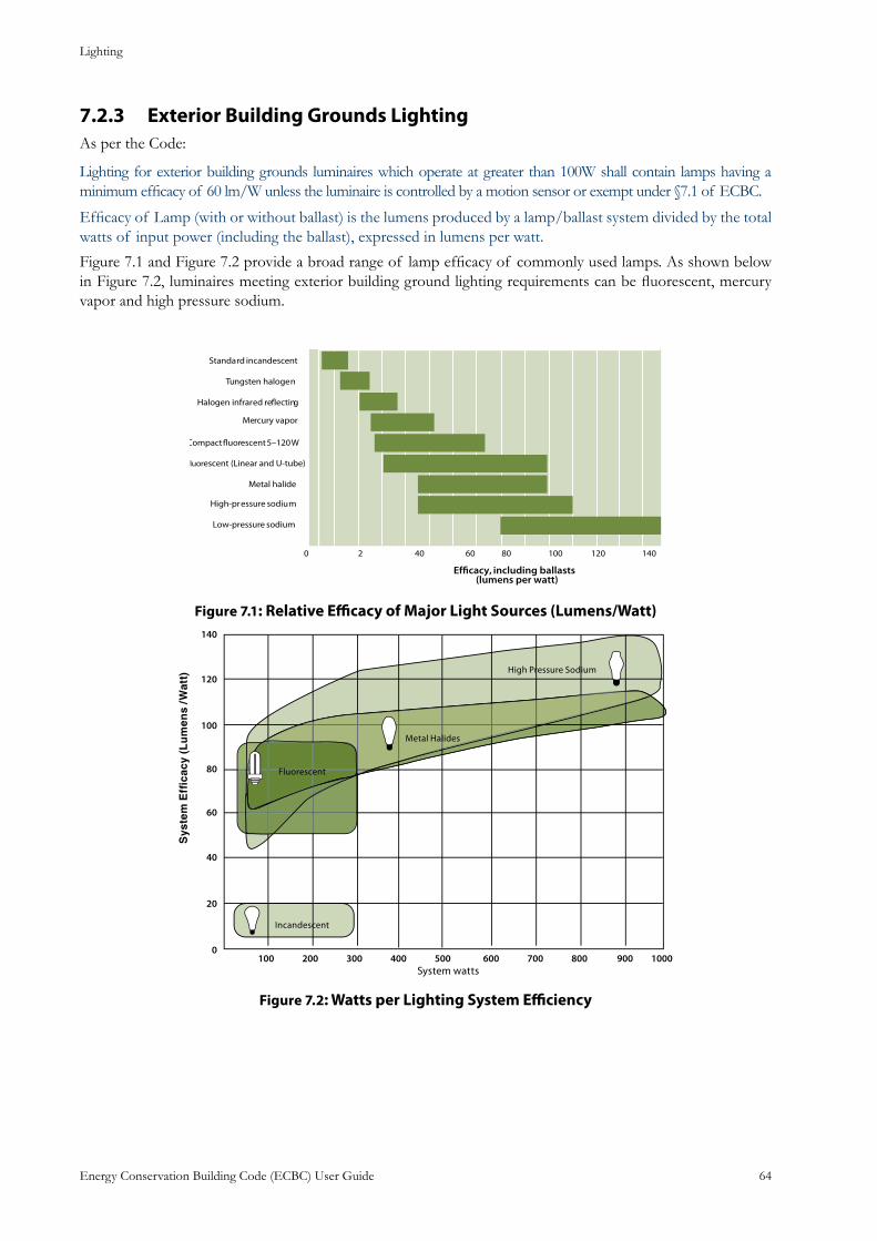
Lighting
Energy Conservation Building Code (ECBC) User Guide 64
Exterior Building Grounds Lighting7.2.3 As per the Code:
Lighting for exterior building grounds luminaires which operate at greater than 100W shall contain lamps having a minimum efficacy of 60 lm/W unless the luminaire is controlled by a motion sensor or exempt under §7.1 of ECBC.
Efficacy of Lamp (with or without ballast) is the lumens produced by a lamp/ballast system divided by the total watts of input power (including the ballast), expressed in lumens per watt.
Figure 7.1 and Figure 7.2 provide a broad range of lamp efficacy of commonly used lamps. As shown below in Figure 7.2, luminaires meeting exterior building ground lighting requirements can be fluorescent, mercury vapor and high pressure sodium.
: Relative Efficacy of Major Light Sources (Lumens/Watt) Figure 7.1
: Watts per Lighting System EfficiencyFigure 7.2
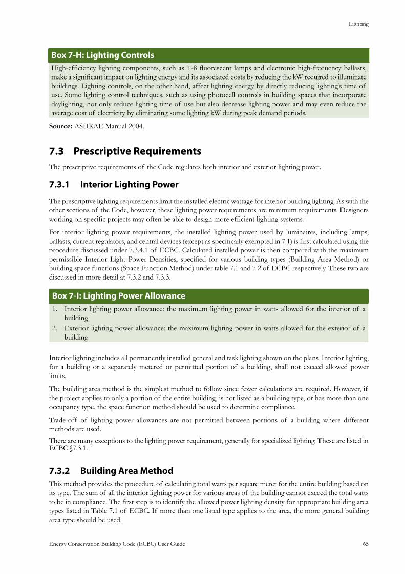
Lighting
Energy Conservation Building Code (ECBC) User Guide 65
: Lighting ControlsBox 7-HHigh-efficiency lighting components, such as T-8 fluorescent lamps and electronic high-frequency ballasts, make a significant impact on lighting energy and its associated costs by reducing the kW required to illuminate buildings. Lighting controls, on the other hand, affect lighting energy by directly reducing lighting’s time of use. Some lighting control techniques, such as using photocell controls in building spaces that incorporate daylighting, not only reduce lighting time of use but also decrease lighting power and may even reduce the average cost of electricity by eliminating some lighting kW during peak demand periods.
Source: ASHRAE Manual 2004.
Prescriptive Requirements7.3 The prescriptive requirements of the Code regulates both interior and exterior lighting power.
Interior Lighting Power7.3.1
The prescriptive lighting requirements limit the installed electric wattage for interior building lighting. As with the other sections of the Code, however, these lighting power requirements are minimum requirements. Designers working on specific projects may often be able to design more efficient lighting systems.
For interior lighting power requirements, the installed lighting power used by luminaires, including lamps, ballasts, current regulators, and central devices (except as specifically exempted in 7.1) is first calculated using the procedure discussed under 7.3.4.1 of ECBC. Calculated installed power is then compared with the maximum permissible Interior Light Power Densities, specified for various building types (Building Area Method) or building space functions (Space Function Method) under table 7.1 and 7.2 of ECBC respectively. These two are discussed in more detail at 7.3.2 and 7.3.3.
: Lighting Power AllowanceBox 7-IInterior lighting power allowance: the maximum lighting power in watts allowed for the interior of a 1. buildingExterior lighting power allowance: the maximum lighting power in watts allowed for the exterior of a 2. building
Interior lighting includes all permanently installed general and task lighting shown on the plans. Interior lighting, for a building or a separately metered or permitted portion of a building, shall not exceed allowed power limits.
The building area method is the simplest method to follow since fewer calculations are required. However, if the project applies to only a portion of the entire building, is not listed as a building type, or has more than one occupancy type, the space function method should be used to determine compliance.
Trade-off of lighting power allowances are not permitted between portions of a building where different methods are used.
There are many exceptions to the lighting power requirement, generally for specialized lighting. These are listed in ECBC §7.3.1.
Building Area Method7.3.2 This method provides the procedure of calculating total watts per square meter for the entire building based on its type. The sum of all the interior lighting power for various areas of the building cannot exceed the total watts to be in compliance. The first step is to identify the allowed power lighting density for appropriate building area types listed in Table 7.1 of ECBC. If more than one listed type applies to the area, the more general building area type should be used.
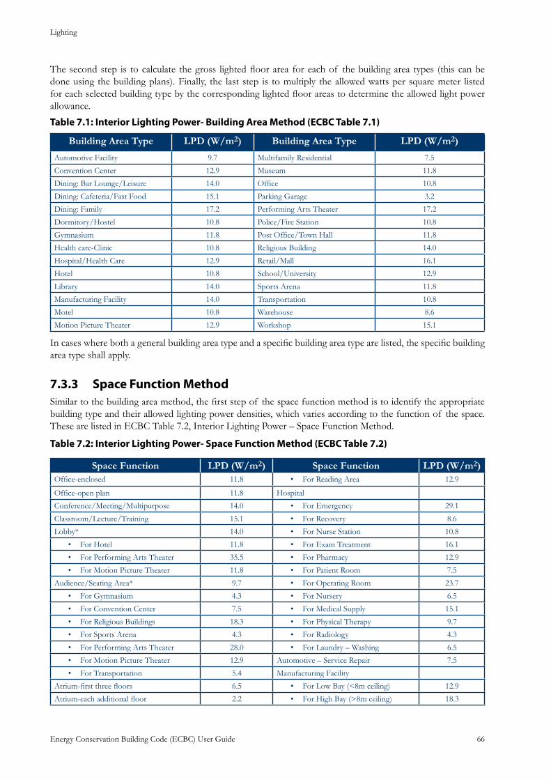
Lighting
Energy Conservation Building Code (ECBC) User Guide 66
The second step is to calculate the gross lighted floor area for each of the building area types (this can be done using the building plans). Finally, the last step is to multiply the allowed watts per square meter listed for each selected building type by the corresponding lighted floor areas to determine the allowed light power allowance.
Table 7.1: Interior Lighting Power- Building Area Method (ECBC Table 7.1)
Building Area Type LPD (W/m2) Building Area Type LPD (W/m2)
Automotive Facility 9.7 Multifamily Residential 7.5
Convention Center 12.9 Museum 11.8
Dining: Bar Lounge/Leisure 14.0 Office 10.8
Dining: Cafeteria/Fast Food 15.1 Parking Garage 3.2
Dining: Family 17.2 Performing Arts Theater 17.2
Dormitory/Hostel 10.8 Police/Fire Station 10.8
Gymnasium 11.8 Post Office/Town Hall 11.8
Health care-Clinic 10.8 Religious Building 14.0
Hospital/Health Care 12.9 Retail/Mall 16.1
Hotel 10.8 School/University 12.9
Library 14.0 Sports Arena 11.8
Manufacturing Facility 14.0 Transportation 10.8
Motel 10.8 Warehouse 8.6
Motion Picture Theater 12.9 Workshop 15.1
In cases where both a general building area type and a specific building area type are listed, the specific building area type shall apply.
Space Function Method7.3.3 Similar to the building area method, the first step of the space function method is to identify the appropriate building type and their allowed lighting power densities, which varies according to the function of the space. These are listed in ECBC Table 7.2, Interior Lighting Power – Space Function Method.
: Interior Lighting Power- Space Function Method (ECBC Table 7.2)Table 7.2
Space Function LPD (W/m2) Space Function LPD (W/m2)Office-enclosed 11.8 For Reading Area• 12.9
Office-open plan 11.8 Hospital
Conference/Meeting/Multipurpose 14.0 For Emergency• 29.1
Classroom/Lecture/Training 15.1 For Recovery• 8.6
Lobby* 14.0 For Nurse Station• 10.8
For Hotel• 11.8 For Exam Treatment• 16.1
For Performing Arts Theater• 35.5 For Pharmacy• 12.9
For Motion Picture Theater• 11.8 For Patient Room• 7.5
Audience/Seating Area* 9.7 For Operating Room• 23.7
For Gymnasium• 4.3 For Nursery• 6.5
For Convention Center• 7.5 For Medical Supply• 15.1
For Religious Buildings• 18.3 For Physical Therapy• 9.7
For Sports Arena• 4.3 For Radiology• 4.3
For Performing Arts Theater• 28.0 For Laundry – Washing• 6.5
For Motion Picture Theater• 12.9 Automotive – Service Repair 7.5
For Transportation• 5.4 Manufacturing Facility
Atrium-first three floors 6.5 For Low Bay (<8m ceiling)• 12.9
Atrium-each additional floor 2.2 For High Bay (>8m ceiling)• 18.3
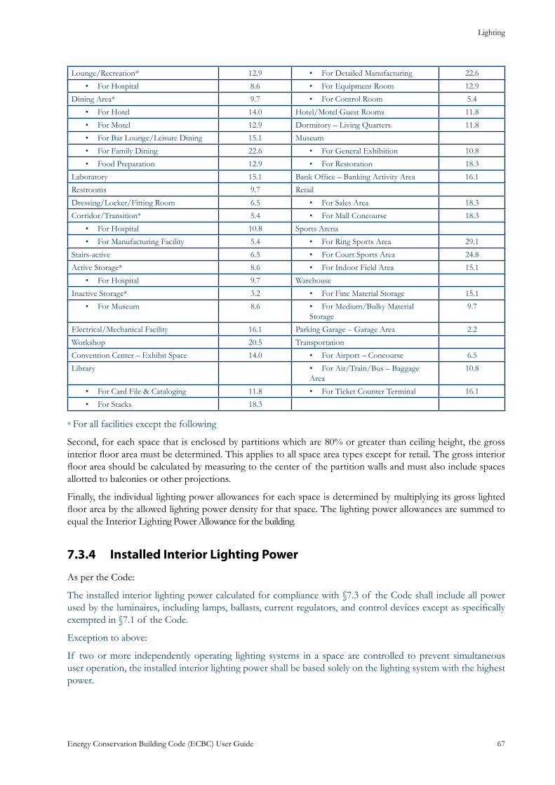
Lighting
Energy Conservation Building Code (ECBC) User Guide 67
Lounge/Recreation* 12.9 For Detailed Manufacturing• 22.6
For Hospital• 8.6 For Equipment Room• 12.9
Dining Area* 9.7 For Control Room• 5.4
For Hotel• 14.0 Hotel/Motel Guest Rooms 11.8
For Motel• 12.9 Dormitory – Living Quarters 11.8
For Bar Lounge/Leisure Dining• 15.1 Museum
For Family Dining• 22.6 For General Exhibition• 10.8
Food Preparation• 12.9 For Restoration• 18.3
Laboratory 15.1 Bank Office – Banking Activity Area 16.1
Restrooms 9.7 Retail
Dressing/Locker/Fitting Room 6.5 For Sales Area• 18.3
Corridor/Transition* 5.4 For Mall Concourse• 18.3
For Hospital• 10.8 Sports Arena
For Manufacturing Facility• 5.4 For Ring Sports Area• 29.1
Stairs-active 6.5 For Court Sports Area• 24.8
Active Storage* 8.6 For Indoor Field Area• 15.1
For Hospital• 9.7 Warehouse
Inactive Storage* 3.2 For Fine Material Storage• 15.1
For Museum• 8.6 For Medium/Bulky Material • Storage
9.7
Electrical/Mechanical Facility 16.1 Parking Garage – Garage Area 2.2
Workshop 20.5 Transportation
Convention Center – Exhibit Space 14.0 For Airport – Concourse• 6.5
Library For Air/Train/Bus – Baggage • Area
10.8
For Card File & Cataloging• 11.8 For Ticket Counter Terminal• 16.1
For Stacks• 18.3
* For all facilities except the following
Second, for each space that is enclosed by partitions which are 80% or greater than ceiling height, the gross interior floor area must be determined. This applies to all space area types except for retail. The gross interior floor area should be calculated by measuring to the center of the partition walls and must also include spaces allotted to balconies or other projections.
Finally, the individual lighting power allowances for each space is determined by multiplying its gross lighted floor area by the allowed lighting power density for that space. The lighting power allowances are summed to equal the Interior Lighting Power Allowance for the building.
Installed Interior Lighting Power7.3.4
As per the Code:
The installed interior lighting power calculated for compliance with §7.3 of the Code shall include all power used by the luminaires, including lamps, ballasts, current regulators, and control devices except as specifically exempted in §7.1 of the Code.
Exception to above:
If two or more independently operating lighting systems in a space are controlled to prevent simultaneous user operation, the installed interior lighting power shall be based solely on the lighting system with the highest power.
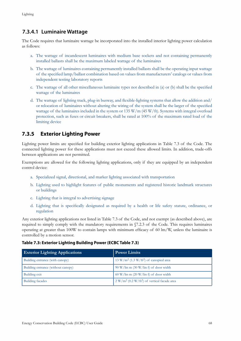
Lighting
Energy Conservation Building Code (ECBC) User Guide 68
Luminaire Wattage7.3.4.1 The Code requires that luminaire wattage be incorporated into the installed interior lighting power calculation as follows:
The wattage of incandescent luminaires with medium base sockets and not containing permanently a. installed ballasts shall be the maximum labeled wattage of the luminaires
The wattage of luminaires containing permanently installed ballasts shall be the operating input wattage b. of the specified lamp/ballast combination based on values from manufacturers’ catalogs or values from independent testing laboratory reports
The wattage of all other miscellaneous luminaire types not described in (a) or (b) shall be the specified c. wattage of the luminaires
The wattage of lighting track, plug-in busway, and flexible-lighting systems that allow the addition and/d. or relocation of luminaires without altering the wiring of the system shall be the larger of the specified wattage of the luminaires included in the system or 135 W/m (45 W/ft). Systems with integral overload protection, such as fuses or circuit breakers, shall be rated at 100% of the maximum rated load of the limiting device
Exterior Lighting Power7.3.5
Lighting power limits are specified for building exterior lighting applications in Table 7.3 of the Code. The connected lighting power for these applications must not exceed these allowed limits. In addition, trade-offs between applications are not permitted.
Exemptions are allowed for the following lighting applications, only if they are equipped by an independent control device:
Specialized signal, directional, and marker lighting associated with transportationa.
Lighting used to highlight features of public monuments and registered historic landmark structures b. or buildings
Lighting that is integral to advertising signage c.
Lighting that is specifically designated as required by a health or life safety statute, ordinance, or d. regulation
Any exterior lighting applications not listed in Table 7.3 of the Code, and not exempt (as described above), are required to simply comply with the mandatory requirements in §7.2.3 of the Code. This requires luminaires operating at greater than 100W to contain lamps with minimum efficacy of 60 lm/W, unless the luminaire is controlled by a motion sensor.
Table 7.3: Exterior Lighting Building Power (ECBC Table 7.3)
Exterior Lighting Applications Power Limits
Building entrance (with canopy) 13 W/m2 (1.3 W/ft2) of canopied area
Building entrance (without canopy) 90 W/lin m (30 W/lin f) of door width
Building exit 60 W/lin m (20 W/lin f) of door width
Building facades 2 W/m2 (0.2 W/ft2) of vertical facade area
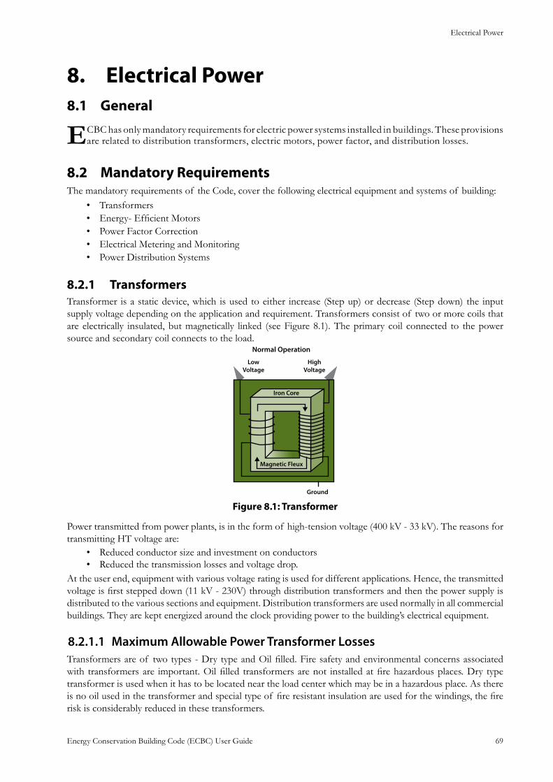
Electrical Power
Energy Conservation Building Code (ECBC) User Guide 69
Electrical Power8. General8.1
ECBC has only mandatory requirements for electric power systems installed in buildings. These provisions are related to distribution transformers, electric motors, power factor, and distribution losses.
Mandatory Requirements8.2 The mandatory requirements of the Code, cover the following electrical equipment and systems of building:
Transformers• Energy- Efficient Motors• Power Factor Correction• Electrical Metering and Monitoring• Power Distribution Systems•
Transformers8.2.1 Transformer is a static device, which is used to either increase (Step up) or decrease (Step down) the input supply voltage depending on the application and requirement. Transformers consist of two or more coils that are electrically insulated, but magnetically linked (see Figure 8.1). The primary coil connected to the power source and secondary coil connects to the load.
: TransformerFigure 8.1
Power transmitted from power plants, is in the form of high-tension voltage (400 kV - 33 kV). The reasons for transmitting HT voltage are:
Reduced conductor size and investment on conductors• Reduced the transmission losses and voltage drop.•
At the user end, equipment with various voltage rating is used for different applications. Hence, the transmitted voltage is first stepped down (11 kV - 230V) through distribution transformers and then the power supply is distributed to the various sections and equipment. Distribution transformers are used normally in all commercial buildings. They are kept energized around the clock providing power to the building’s electrical equipment.
Maximum Allowable Power Transformer Losses8.2.1.1 Transformers are of two types - Dry type and Oil filled. Fire safety and environmental concerns associated with transformers are important. Oil filled transformers are not installed at fire hazardous places. Dry type transformer is used when it has to be located near the load center which may be in a hazardous place. As there is no oil used in the transformer and special type of fire resistant insulation are used for the windings, the fire risk is considerably reduced in these transformers.
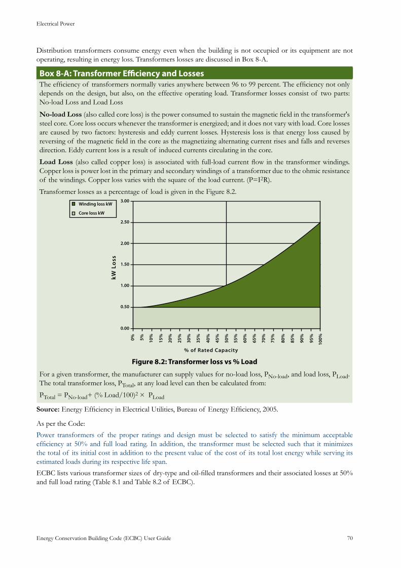
Electrical Power
Energy Conservation Building Code (ECBC) User Guide 70
Distribution transformers consume energy even when the building is not occupied or its equipment are not operating, resulting in energy loss. Transformers losses are discussed in Box 8-A.
: Transformer Efficiency and Losses Box 8-AThe efficiency of transformers normally varies anywhere between 96 to 99 percent. The efficiency not only depends on the design, but also, on the effective operating load. Transformer losses consist of two parts: No-load Loss and Load Loss
No-load Loss (also called core loss) is the power consumed to sustain the magnetic field in the transformer's steel core. Core loss occurs whenever the transformer is energized; and it does not vary with load. Core losses are caused by two factors: hysteresis and eddy current losses. Hysteresis loss is that energy loss caused by reversing of the magnetic field in the core as the magnetizing alternating current rises and falls and reverses direction. Eddy current loss is a result of induced currents circulating in the core.
Load Loss (also called copper loss) is associated with full-load current flow in the transformer windings. Copper loss is power lost in the primary and secondary windings of a transformer due to the ohmic resistance of the windings. Copper loss varies with the square of the load current. (P=I2R).
Transformer losses as a percentage of load is given in the Figure 8.2.
:Figure 8.2 Transformer loss vs % Load
For a given transformer, the manufacturer can supply values for no-load loss, PNo-load, and load loss, PLoad. The total transformer loss, PTotal, at any load level can then be calculated from:
PTotal = PNo-load+ (% Load/100)2 × PLoad
Source: Energy Efficiency in Electrical Utilities, Bureau of Energy Efficiency, 2005.
As per the Code:
Power transformers of the proper ratings and design must be selected to satisfy the minimum acceptable efficiency at 50% and full load rating. In addition, the transformer must be selected such that it minimizes the total of its initial cost in addition to the present value of the cost of its total lost energy while serving its estimated loads during its respective life span.
ECBC lists various transformer sizes of dry-type and oil-filled transformers and their associated losses at 50% and full load rating (Table 8.1 and Table 8.2 of ECBC).
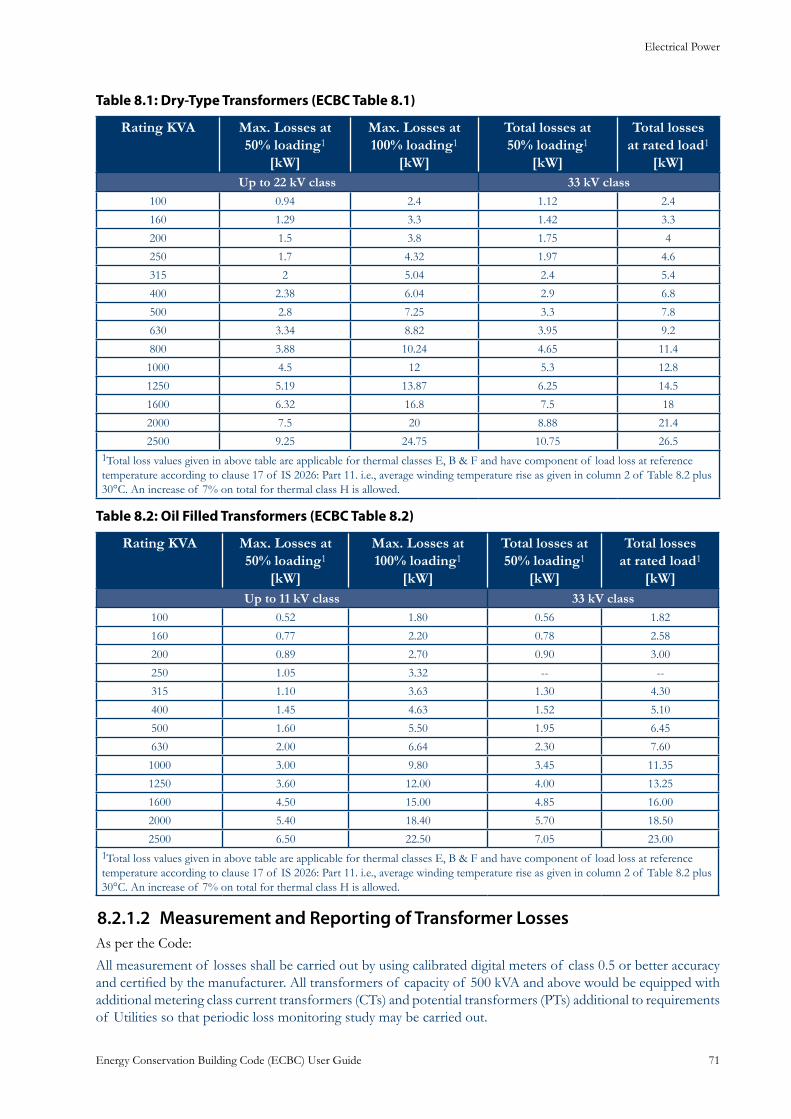
Electrical Power
Energy Conservation Building Code (ECBC) User Guide 71
Table 8.1: Dry-Type Transformers (ECBC Table 8.1)
Rating KVA Max. Losses at 50% loading1
[kW]
Max. Losses at 100% loading1
[kW]
Total losses at 50% loading1
[kW]
Total losses at rated load1
[kW]Up to 22 kV class 33 kV class
100 0.94 2.4 1.12 2.4
160 1.29 3.3 1.42 3.3
200 1.5 3.8 1.75 4
250 1.7 4.32 1.97 4.6
315 2 5.04 2.4 5.4
400 2.38 6.04 2.9 6.8
500 2.8 7.25 3.3 7.8
630 3.34 8.82 3.95 9.2
800 3.88 10.24 4.65 11.4
1000 4.5 12 5.3 12.8
1250 5.19 13.87 6.25 14.5
1600 6.32 16.8 7.5 18
2000 7.5 20 8.88 21.4
2500 9.25 24.75 10.75 26.51Total loss values given in above table are applicable for thermal classes E, B & F and have component of load loss at reference temperature according to clause 17 of IS 2026: Part 11. i.e., average winding temperature rise as given in column 2 of Table 8.2 plus 30°C. An increase of 7% on total for thermal class H is allowed.
Table 8.2: Oil Filled Transformers (ECBC Table 8.2)
Rating KVA Max. Losses at 50% loading1
[kW]
Max. Losses at 100% loading1
[kW]
Total losses at 50% loading1
[kW]
Total losses at rated load1
[kW]Up to 11 kV class 33 kV class
100 0.52 1.80 0.56 1.82
160 0.77 2.20 0.78 2.58
200 0.89 2.70 0.90 3.00
250 1.05 3.32 -- --
315 1.10 3.63 1.30 4.30
400 1.45 4.63 1.52 5.10
500 1.60 5.50 1.95 6.45
630 2.00 6.64 2.30 7.60
1000 3.00 9.80 3.45 11.35
1250 3.60 12.00 4.00 13.25
1600 4.50 15.00 4.85 16.00
2000 5.40 18.40 5.70 18.50
2500 6.50 22.50 7.05 23.001Total loss values given in above table are applicable for thermal classes E, B & F and have component of load loss at reference temperature according to clause 17 of IS 2026: Part 11. i.e., average winding temperature rise as given in column 2 of Table 8.2 plus 30°C. An increase of 7% on total for thermal class H is allowed.
Measurement and Reporting of Transformer Losses 8.2.1.2 As per the Code:
All measurement of losses shall be carried out by using calibrated digital meters of class 0.5 or better accuracy and certified by the manufacturer. All transformers of capacity of 500 kVA and above would be equipped with additional metering class current transformers (CTs) and potential transformers (PTs) additional to requirements of Utilities so that periodic loss monitoring study may be carried out.
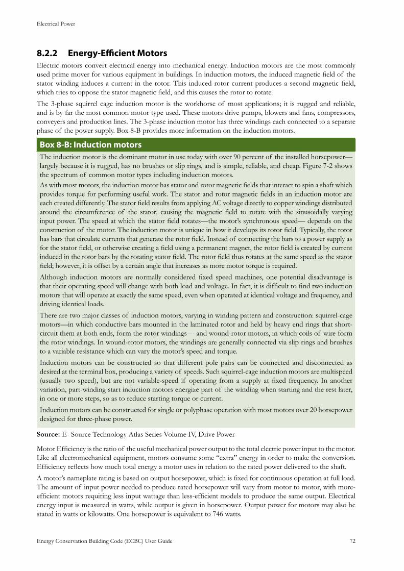
Electrical Power
Energy Conservation Building Code (ECBC) User Guide 72
Energy-Efficient Motors8.2.2 Electric motors convert electrical energy into mechanical energy. Induction motors are the most commonly used prime mover for various equipment in buildings. In induction motors, the induced magnetic field of the stator winding induces a current in the rotor. This induced rotor current produces a second magnetic field, which tries to oppose the stator magnetic field, and this causes the rotor to rotate.
The 3-phase squirrel cage induction motor is the workhorse of most applications; it is rugged and reliable, and is by far the most common motor type used. These motors drive pumps, blowers and fans, compressors, conveyers and production lines. The 3-phase induction motor has three windings each connected to a separate phase of the power supply. Box 8-B provides more information on the induction motors.
: Induction motorsBox 8-BThe induction motor is the dominant motor in use today with over 90 percent of the installed horsepower—largely because it is rugged, has no brushes or slip rings, and is simple, reliable, and cheap. Figure 7-2 shows the spectrum of common motor types including induction motors.As with most motors, the induction motor has stator and rotor magnetic fields that interact to spin a shaft which provides torque for performing useful work. The stator and rotor magnetic fields in an induction motor are each created differently. The stator field results from applying AC voltage directly to copper windings distributed around the circumference of the stator, causing the magnetic field to rotate with the sinusoidally varying input power. The speed at which the stator field rotates—the motor’s synchronous speed— depends on the construction of the motor. The induction motor is unique in how it develops its rotor field. Typically, the rotor has bars that circulate currents that generate the rotor field. Instead of connecting the bars to a power supply as for the stator field, or otherwise creating a field using a permanent magnet, the rotor field is created by current induced in the rotor bars by the rotating stator field. The rotor field thus rotates at the same speed as the stator field; however, it is offset by a certain angle that increases as more motor torque is required.
Although induction motors are normally considered fixed speed machines, one potential disadvantage is that their operating speed will change with both load and voltage. In fact, it is difficult to find two induction motors that will operate at exactly the same speed, even when operated at identical voltage and frequency, and driving identical loads.
There are two major classes of induction motors, varying in winding pattern and construction: squirrel-cage motors—in which conductive bars mounted in the laminated rotor and held by heavy end rings that short-circuit them at both ends, form the rotor windings— and wound-rotor motors, in which coils of wire form the rotor windings. In wound-rotor motors, the windings are generally connected via slip rings and brushes to a variable resistance which can vary the motor’s speed and torque.
Induction motors can be constructed so that different pole pairs can be connected and disconnected as desired at the terminal box, producing a variety of speeds. Such squirrel-cage induction motors are multispeed (usually two speed), but are not variable-speed if operating from a supply at fixed frequency. In another variation, part-winding start induction motors energize part of the winding when starting and the rest later, in one or more steps, so as to reduce starting torque or current.
Induction motors can be constructed for single or polyphase operation with most motors over 20 horsepower designed for three-phase power.
Source: E- Source Technology Atlas Series Volume IV, Drive Power
Motor Efficiency is the ratio of the useful mechanical power output to the total electric power input to the motor. Like all electromechanical equipment, motors consume some “extra” energy in order to make the conversion. Efficiency reflects how much total energy a motor uses in relation to the rated power delivered to the shaft.
A motor’s nameplate rating is based on output horsepower, which is fixed for continuous operation at full load. The amount of input power needed to produce rated horsepower will vary from motor to motor, with more-efficient motors requiring less input wattage than less-efficient models to produce the same output. Electrical energy input is measured in watts, while output is given in horsepower. Output power for motors may also be stated in watts or kilowatts. One horsepower is equivalent to 746 watts.
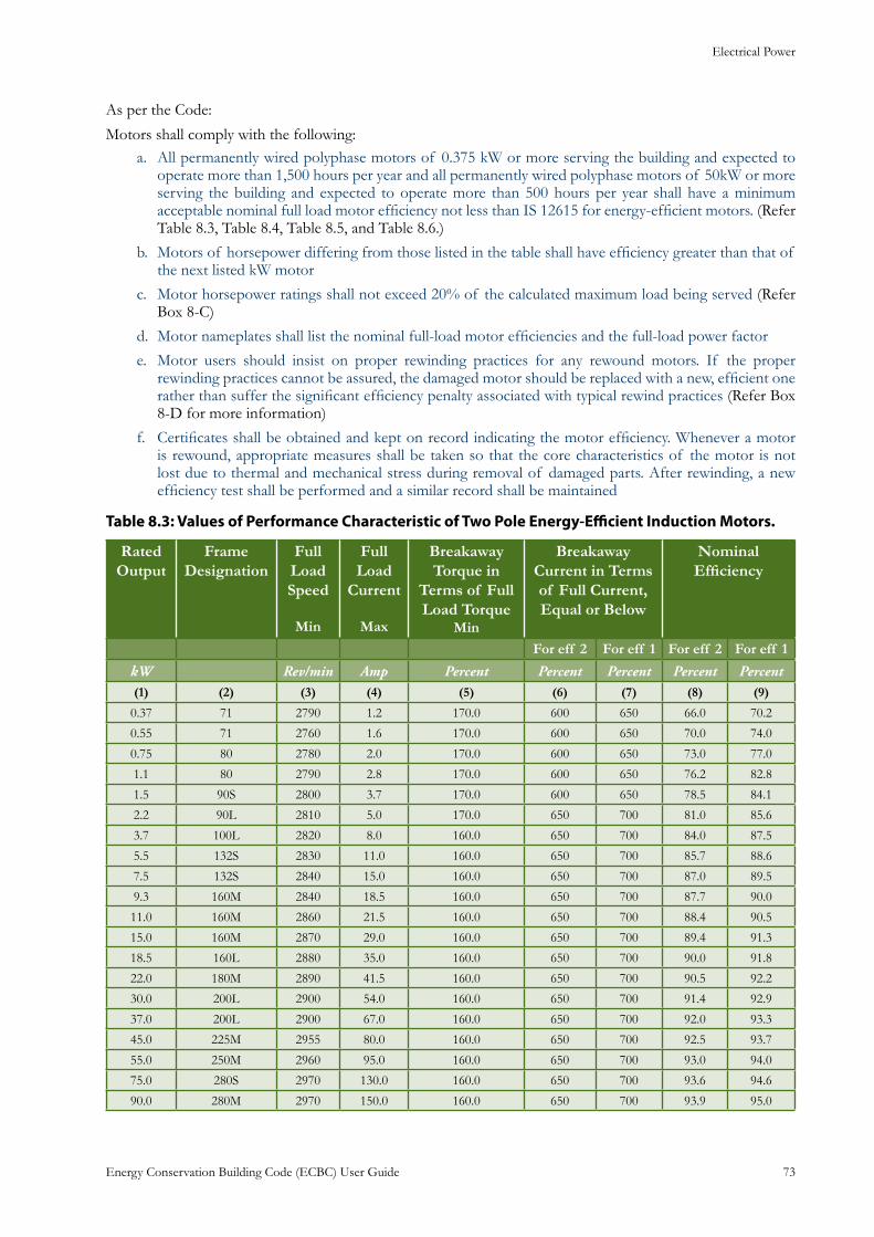
Electrical Power
Energy Conservation Building Code (ECBC) User Guide 73
As per the Code:
Motors shall comply with the following:All permanently wired polyphase motors of 0.375 kW or more serving the building and expected to a. operate more than 1,500 hours per year and all permanently wired polyphase motors of 50kW or more serving the building and expected to operate more than 500 hours per year shall have a minimum acceptable nominal full load motor efficiency not less than IS 12615 for energy-efficient motors. (Refer Table 8.3, Table 8.4, Table 8.5, and Table 8.6.)
Motors of horsepower differing from those listed in the table shall have efficiency greater than that of b. the next listed kW motor
Motor horsepower ratings shall not exceed 20% of the calculated maximum load being servedc. (Refer Box 8-C)
Motor nameplates shall list the nominal full-load motor efficiencies and the full-load power factord.
Motor users should insist on proper rewinding practices for any rewound motors. If the proper e. rewinding practices cannot be assured, the damaged motor should be replaced with a new, efficient one rather than suffer the significant efficiency penalty associated with typical rewind practices (Refer Box 8-D for more information)
Certificates shall be obtained and kept on record indicating the motor efficiency. Whenever a motor f. is rewound, appropriate measures shall be taken so that the core characteristics of the motor is not lost due to thermal and mechanical stress during removal of damaged parts. After rewinding, a new efficiency test shall be performed and a similar record shall be maintained
Table 8.3: Values of Performance Characteristic of Two Pole Energy-Efficient Induction Motors.
Rated Output
Frame Designation
Full Load Speed
Min
Full Load
Current
Max
Breakaway Torque in
Terms of Full Load Torque
Min
Breakaway Current in Terms of Full Current, Equal or Below
Nominal Efficiency
For eff 2 For eff 1 For eff 2 For eff 1
kW Rev/min Amp Percent Percent Percent Percent Percent (1) (2) (3) (4) (5) (6) (7) (8) (9)
0.37 71 2790 1.2 170.0 600 650 66.0 70.2
0.55 71 2760 1.6 170.0 600 650 70.0 74.0
0.75 80 2780 2.0 170.0 600 650 73.0 77.0
1.1 80 2790 2.8 170.0 600 650 76.2 82.8
1.5 90S 2800 3.7 170.0 600 650 78.5 84.1
2.2 90L 2810 5.0 170.0 650 700 81.0 85.6
3.7 100L 2820 8.0 160.0 650 700 84.0 87.5
5.5 132S 2830 11.0 160.0 650 700 85.7 88.6
7.5 132S 2840 15.0 160.0 650 700 87.0 89.5
9.3 160M 2840 18.5 160.0 650 700 87.7 90.0
11.0 160M 2860 21.5 160.0 650 700 88.4 90.5
15.0 160M 2870 29.0 160.0 650 700 89.4 91.3
18.5 160L 2880 35.0 160.0 650 700 90.0 91.8
22.0 180M 2890 41.5 160.0 650 700 90.5 92.2
30.0 200L 2900 54.0 160.0 650 700 91.4 92.9
37.0 200L 2900 67.0 160.0 650 700 92.0 93.3
45.0 225M 2955 80.0 160.0 650 700 92.5 93.7
55.0 250M 2960 95.0 160.0 650 700 93.0 94.0
75.0 280S 2970 130.0 160.0 650 700 93.6 94.6
90.0 280M 2970 150.0 160.0 650 700 93.9 95.0
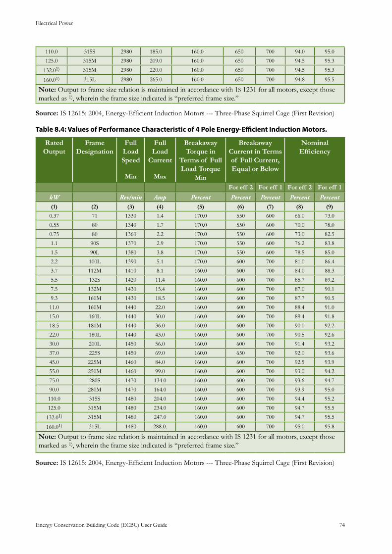
Electrical Power
Energy Conservation Building Code (ECBC) User Guide 74
110.0 315S 2980 185.0 160.0 650 700 94.0 95.0
125.0 315M 2980 209.0 160.0 650 700 94.5 95.3
132.01) 315M 2980 220.0 160.0 650 700 94.5 95.3
160.01) 315L 2980 265.0 160.0 650 700 94.8 95.5
Note: Output to frame size relation is maintained in accordance with 1S 1231 for all motors, except those marked as 1), wherein the frame size indicated is “preferred frame size.”
Source: IS 12615: 2004, Energy-Efficient Induction Motors --- Three-Phase Squirrel Cage (First Revision)
Table 8.4: Values of Performance Characteristic of 4 Pole Energy-Efficient Induction Motors.
Rated Output
Frame Designation
Full Load Speed
Min
Full Load
Current
Max
Breakaway Torque in
Terms of Full Load Torque
Min
Breakaway Current in Terms of Full Current, Equal or Below
Nominal Efficiency
For eff 2 For eff 1 For eff 2 For eff 1
kW Rev/min Amp Percent Percent Percent Percent Percent (1) (2) (3) (4) (5) (6) (7) (8) (9)
0.37 71 1330 1.4 170.0 550 600 66.0 73.0
0.55 80 1340 1.7 170.0 550 600 70.0 78.0
0.75 80 1360 2.2 170.0 550 600 73.0 82.5
1.1 90S 1370 2.9 170.0 550 600 76.2 83.8
1.5 90L 1380 3.8 170.0 550 600 78.5 85.0
2.2 100L 1390 5.1 170.0 600 700 81.0 86.4
3.7 112M 1410 8.1 160.0 600 700 84.0 88.3
5.5 132S 1420 11.4 160.0 600 700 85.7 89.2
7.5 132M 1430 15.4 160.0 600 700 87.0 90.1
9.3 160M 1430 18.5 160.0 600 700 87.7 90.5
11.0 160M 1440 22.0 160.0 600 700 88.4 91.0
15.0 160L 1440 30.0 160.0 600 700 89.4 91.8
18.5 180M 1440 36.0 160.0 600 700 90.0 92.2
22.0 180L 1440 43.0 160.0 600 700 90.5 92.6
30.0 200L 1450 56.0 160.0 600 700 91.4 93.2
37.0 225S 1450 69.0 160.0 650 700 92.0 93.6
45.0 225M 1460 84.0 160.0 600 700 92.5 93.9
55.0 250M 1460 99.0 160.0 600 700 93.0 94.2
75.0 280S 1470 134.0 160.0 600 700 93.6 94.7
90.0 280M 1470 164.0 160.0 600 700 93.9 95.0
110.0 315S 1480 204.0 160.0 600 700 94.4 95.2
125.0 315M 1480 234.0 160.0 600 700 94.7 95.5
132.01) 315M 1480 247.0 160.0 600 700 94.7 95.5
160.01) 315L 1480 288.0. 160.0 600 700 95.0 95.8
Note: Output to frame size relation is maintained in accordance with IS 1231 for all motors, except those marked as 1), wherein the frame size indicated is “preferred frame size.”
Source: IS 12615: 2004, Energy-Efficient Induction Motors --- Three-Phase Squirrel Cage (First Revision)
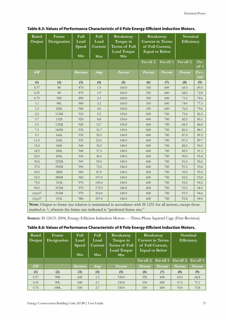
Electrical Power
Energy Conservation Building Code (ECBC) User Guide 75
Table 8.5: Values of Performance Characteristic of 6 Pole Energy-Efficient Induction Motors.
Rated Output
Frame Designation
Full Load Speed
Min
Full Load
Current
Max
Breakaway Torque in
Terms of Full Load Torque
Min
Breakaway Current in Terms of Full Current, Equal or Below
Nominal Efficiency
For eff 2 For eff 1 For eff 2 For eff 1
kW Rev/min Amp Percent Percent Percent Percent P e r -cent
(1) (2) (3) (4) (5) (6) (7) (8) (9)
0.37 80 870 1.4 160.0 550 600 65.0 69.4
0.55 80 870 1.9 160.0 550 600 68.0 72.0
0.75 90S 890 2.3 160.0 550 600 71.0 74.6
1.1 90L 900 3.2 160.0 550 600 74.0 77.3
1.5 100L 900 4.0 160.0 550 600 76.0 79.6
2.2 112M 910 5.5 150.0 600 700 79.0 82.2
3.7 132S 920 8.8 150.0 600 700 82.5 85.1
5.5 132M 920 12.7 150.0 600 700 84.5 86.8
7.5 160M 930 16.7 150.0 600 700 86.0 88.1
9.3 160L 930 20.5 140.0 600 700 87.0 89.3
11.0 160L 935 23.0. 140.0 600 700 87.5 89.7
15.0 180L 940 30.5 140.0 600 700 88.5 90.5
18.5 200L 940 37.5 140.0 600 700 89.5 91.3
22.0 200L 945 44.0 140.0 600 700 90.0 91.8
30.0 225M 945 59.0 140.0 600 700 91.0 92.6
37.0 250M 950 72.0 140.0 600 700 91.5 93.0
45.0 280S 960 87.0 140.0 600 700 92.0 93.4
55.0 280M 960 107.0 140.0 600 700 92.5 93.8
75.0 315S 970 145.0 140.0 600 700 93.0 94.2
90.0 315M 970 175.0 140.0 600 700 93.3 94.5
110.01) 315M 970 214.0 140.0 600 700 93.5 94.6
132.01) 315L 980 257.0 140.0 600 700 93.8 94.9
Note: Output to frame size relation is maintained in accordance with IS 1231 for all motors, except those marked as 1), wherein the frame size indicated is “preferred frame size.”
Source: IS 12615: 2004, Energy-Efficient Induction Motors --- Three-Phase Squirrel Cage (First Revision)
Table 8.6: Values of Performance Characteristic of 8 Pole Energy-Efficient Induction Motors.
Rated Output
Frame Designation
Full Load Speed
Min
Full Load
Current
Max
Breakaway Torque in
Terms of Full Load Torque
Min
Breakaway Current in Terms of Full Current, Equal or Below
Nominal Efficiency
For eff 2 For eff 1 For eff 2 For eff 1
kW Rev/min Amp Percent Percent Percent Percent Percent (1) (2) (3) (4) (5) (6) (7) (8) (9)
0.37 90S 640 1.5 150.0 550 600 62.0 66.8
0.55 90L 640 2.1 150.0 550 600 67.0 71.1
0.75 100L 650 2.7 150.0 550 600 70.0 73.8
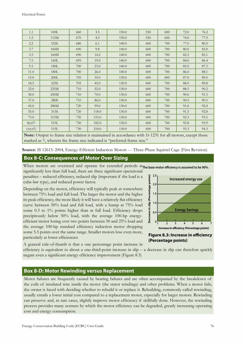
Electrical Power
Energy Conservation Building Code (ECBC) User Guide 76
1.1 100L 660 3.5 150.0 550 600 72.0 76.2
1.5 112M 670 4.5 150.0 550 600 74.0 77.9
2.2 I32S 680 6.1 140.0 600 700 77.0 80.5
3.7 160M 690 9.8 140.0 600 700 80.0 83.0
5.5 160M 690 14.2 140.0 600 700 82.5 85.1
7.5 160L 695 19.0 140.0 600 700 84.0 86.4
9.3 180L 700 23.0 140.0 600 700 85.0 87.3
11.0 180L 700 26.0 140.0 600 700 86.0 88.1
15.0 200L 705 35.0 130.0 600 600 87.0 89.0
18.5 225S 705 45.0 130.0 600 700 88.0 89.8
22.0 225M 710 52.0 130.0 600 700 88.5 90.2
30.0 250M 710 70.0 130.0 600 700 90.0 91.5
37.0 280S 710 86.0 130.0 600 700 90.5 90.5
45.0 280M 720 99.0 130.0 600 700 91.0 92.4
55.0 315S 720 118.0 130.0 600 700 91.5 92.8
75.0 315M 730 153.0 130.0 600 700 92.3 93.5
90.01) 315L 730 182.0 130.0 600 700 92.8 93.9
110.01) 315L 730 218.0 130.0 600 700 93.3 94.3
Note: Output to frame size relation is maintained in accordance with 1S 1231 for all motors, except those marked as 1), wherein the frame size indicated is “preferred frame size.”
Source: IS 12615: 2004, Energy-Efficient Induction Motors --- Three-Phase Squirrel Cage (First Revision)
: Consequences of Motor Over SizingBox 8-CWhen motors are oversized and operate for extended periods at significantly less than full load, there are three significant operational penalties – reduced efficiency, reduced slip (important if the load is a cube-law type), and reduced power factor.
Depending on the motor, efficiency will typically peak at somewhere between 75% load and full load. The larger the motor and the higher its peak efficiency, the more likely it will have a relatively flat efficiency curve between 50% load and full load, with a hump at 75% load some 0.3 to 1% points higher than at full load. Efficiency drops precipitously below 50% load, with the average 100-hp energy-efficient motor losing over two points between 50 and 25% load and the average 100-hp standard efficiency induction motor dropping some 5.5 points over the same range. Smaller motors lose even more, particularly at lower efficiencies
A general rule-of-thumb is that a one percentage point increase in efficiency is equivalent to about a one-third-point increase in slip – a decrease in slip can therefore quickly negate even a significant energy efficiency improvement (Figure 8.3)
: Increase in efficiency Figure 8.3(Percentage points)
: Motor Rewinding versus ReplacementBox 8-DMotor failures are frequently caused by bearing failures and are often accompanied by the breakdown of the coils of insulated wire inside the motor (the stator windings) and other problems. When a motor fails, the owner is faced with deciding whether to rebuild it or replace it. Rebuilding, commonly called rewinding, usually entails a lower initial cost compared to a replacement motor, especially for larger motors. Rewinding can preserve and, in rare cases, slightly improve motor efficiency if skillfully done. However, the rewinding process provides many avenues by which the motor efficiency can be degraded, greatly increasing operating cost and energy consumption.
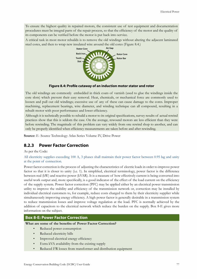
Electrical Power
Energy Conservation Building Code (ECBC) User Guide 77
To ensure the highest quality in repaired motors, the consistent use of test equipment and documentation procedures must be integral parts of the repair process, so that the efficiency of the motor and the quality of its components can be verified before the motor is put back into service.A critical task in most motor rebuilds is to remove the old windings without altering the adjacent laminated steel cores, and then to wrap new insulated wire around the old cores (Figure 8.4.)
Stator Core
Back Iron
ToothSlot
Air Gap
Rotor Core
Rotor Bar
: Profile cutaway of an induction motor stator and rotorFigure 8.4
The old windings are commonly embedded in thick coats of varnish (used to glue the windings inside the core slots) which prevent their easy removal. Heat, chemicals, or mechanical force are commonly used to loosen and pull out old windings; excessive use of any of these can cause damage to the cores. Improper machining, replacement bearings, wire diameter, and winding technique can all compound, resulting in a rebuilt motor with poor performance and lower efficiency.Although it is technically possible to rebuild a motor to its original specifications, survey results of actual rewind practices show that this is seldom the case. On the average, rewound motors are less efficient than they were before rewinding. The magnitude of this problem can vary widely from one rewind shop to another, and can only be properly identified when efficiency measurements are taken before and after rewinding.
Source: E- Source Technology Atlas Series Volume IV, Drive Power
Power Factor Correction8.2.3 As per the Code:
All electricity supplies exceeding 100 A, 3 phases shall maintain their power factor between 0.95 lag and unity at the point of connection.
Power factor correction is the process of adjusting the characteristics of electric loads in order to improve power factor so that it is closer to unity (i.e. 1). In simplified, electrical terminology, power factor is the difference between real (kW) and reactive power (kVAR). It is a measure of how effectively current is being converted into useful work output and, more specifically, is a good indicator of the effect of the load current on the efficiency of the supply system. Power factor correction (PFC) may be applied either by an electrical power transmission utility to improve the stability and efficiency of the transmission network or, correction may be installed by individual electrical customers to, for example, reduce costs charged to them by their electricity supplier while simultaneously improving energy efficiency. A high power factor is generally desirable in a transmission system to reduce transmission losses and improve voltage regulation at the load. PFC is normally achieved by the addition of capacitors to the electrical network which reduce the burden on the supply. Box 8-E gives more information on the subject.
: Power Factor CorrectionBox 8-EWhat are some of the benefits of Power Factor Correction?
Reduced power consumption• Reduced electricity bills• Improved electrical energy efficiency• Extra kVA availability from the existing supply• Reduced I• 2R losses from transformer and distribution equipment
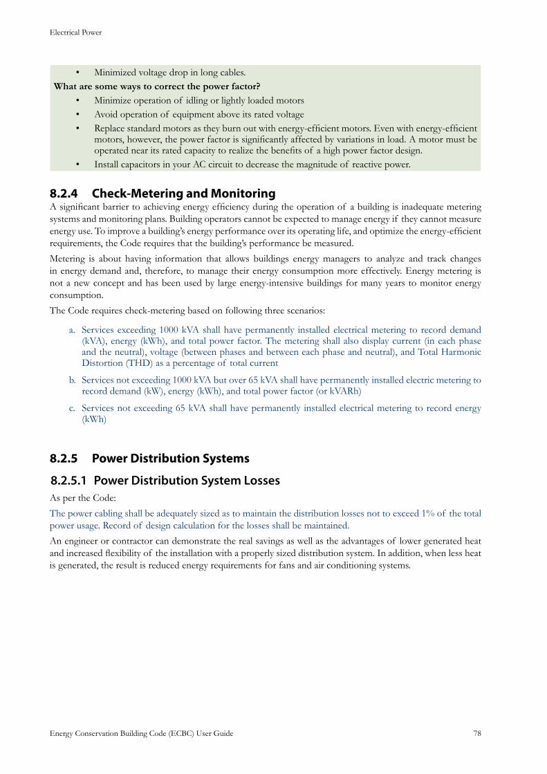
Electrical Power
Energy Conservation Building Code (ECBC) User Guide 78
Minimized voltage drop in long cables.• What are some ways to correct the power factor?
Minimize operation of idling or lightly loaded motors• Avoid operation of equipment above its rated voltage• Replace standard motors as they burn out with energy-efficient motors. Even with energy-efficient • motors, however, the power factor is significantly affected by variations in load. A motor must be operated near its rated capacity to realize the benefits of a high power factor design.Install capacitors in your AC circuit to decrease the magnitude of reactive power.•
Check-Metering and Monitoring8.2.4 A significant barrier to achieving energy efficiency during the operation of a building is inadequate metering systems and monitoring plans. Building operators cannot be expected to manage energy if they cannot measure energy use. To improve a building’s energy performance over its operating life, and optimize the energy-efficient requirements, the Code requires that the building’s performance be measured.
Metering is about having information that allows buildings energy managers to analyze and track changes in energy demand and, therefore, to manage their energy consumption more effectively. Energy metering is not a new concept and has been used by large energy-intensive buildings for many years to monitor energy consumption.
The Code requires check-metering based on following three scenarios:
Services exceeding 1000 kVA shall have permanently installed electrical metering to record demand a. (kVA), energy (kWh), and total power factor. The metering shall also display current (in each phase and the neutral), voltage (between phases and between each phase and neutral), and Total Harmonic Distortion (THD) as a percentage of total current
Services not exceeding 1000 kVA but over 65 kVA shall have permanently installed electric metering to b. record demand (kW), energy (kWh), and total power factor (or kVARh)
Services not exceeding 65 kVA shall have permanently installed electrical metering to record energy c. (kWh)
Power Distribution Systems8.2.5
Power Distribution System Losses8.2.5.1 As per the Code:
The power cabling shall be adequately sized as to maintain the distribution losses not to exceed 1% of the total power usage. Record of design calculation for the losses shall be maintained.
An engineer or contractor can demonstrate the real savings as well as the advantages of lower generated heat and increased flexibility of the installation with a properly sized distribution system. In addition, when less heat is generated, the result is reduced energy requirements for fans and air conditioning systems.
Appendix A: ECBC Definitions, Abbreviations and Acronyms
Energy Conservation Building Code (ECBC) User Guide A.1
APPENDIX A: ECBC Definitions, Abbreviations and Acronyms
General9.1
Certain terms, abbreviations, and acronyms are defined in this section for the purposes of this code. These definitions are applicable to all sections of this code. Terms that are not defined shall have their ordinarily
accepted meanings within the context in which they are used. Webster’s Third New International Dictionary of the English Language, Unabridged, copyright 1986, shall be considered as providing ordinarily accepted meanings.
Definitions9.2 Addition: an extension or increase in floor area or height of a building outside of the existing building envelope
Alteration: any change, rearrangement, replacement, or addition to a building or its systems and equipment; any modification in construction or building equipment
Annual fuel utilization efficiency (AFUE): an efficiency description of the ratio of annual output energy to annual input energy as developed in accordance with requirements of U.S. Department of Energy (DOE) 10CFR Part 430
Astronomical time switch: an automatic time switch that makes an adjustment for the length of the day as it varies over the year
Authority having jurisdiction: the agency or agent responsible for enforcing this Code
Automatic: self-acting, operating by its own mechanism when actuated by some non-manual influence, such as a change in current strength, pressure, temperature, or mechanical configuration.
Automatic control device: a device capable of automatically turning loads off and on without manual intervention
Balancing, air system: adjusting airflow rates through air distribution system devices, such as fans and diffusers, by manually adjusting the position of dampers, splitters vanes, extractors, etc., or by using automatic control devices, such as constant air volume or variable air volume boxes
Balancing, hydronic system: adjusting water flow rates through hydronic distribution system devices, such as pumps and coils, by manually adjusting the position valves, or by using automatic control devices, such as automatic flow control valves
Ballast: a device used in conjunction with an electric-discharge lamp to cause the lamp to start and operate under proper circuit conations of voltage, current, waveform, electrode heat, etc.
Boiler: a self-contained low-pressure appliance for supplying steam or hot water
Boiler, packaged: a boiler that is shipped complete with heating equipment, mechanical draft equipment, and automatic controls; usually shipped in one or more sections. A packaged boiler includes factory-built boilers manufactured as a unit or system, disassembled for shipment, and reassembled at the site.
Building: a structure wholly or partially enclosed within exterior walls, or within exterior and party walls, and a roof, affording shelter to persons, animals, or property.
Appendix A: ECBC Definitions, Abbreviations and Acronyms
Energy Conservation Building Code (ECBC) User Guide A.2
Building, existing: a building or portion thereof that was previously occupied or approved for occupancy by the Authority Having Jurisdiction
Building complex: a group of buildings in a contiguous area under single ownership
Building entrance: any doorway, set of doors, turnstiles, or other form of portal that is ordinarily used to gain access to the building by its users and occupants
Building envelope: the exterior plus the semi-exterior portions of a building. For the purposes of determining building envelope requirements, the classifications are defined as follows:
Building envelope, exterior: the elements of a building that separate conditioned spaces from the exterior
Building envelope, semi-exterior: the elements of a building that separate conditioned space from unconditioned space or that enclose semi-heated spaces through which thermal energy may be transferred to or from the exterior, or to or from unconditioned spaces, or to or from conditioned spaces
Building exit: any doorway, set of doors, or other form of portal that is ordinarily used only for emergency egress or convenience exit
Building grounds lighting: lighting provided through a building’s electrical service for parking lot, site, roadway, pedestrian pathway, loading dock, and security applications
Building material: any element of the building envelope through which heat flows and that heat is included in the component U-factor calculations other than air films and insulation
Circuit breaker: a device designed to open and close a circuit by nonautomatic means and to open the circuit automatically at a predetermined over-current without damage to itself when properly applied within its rating
Class of construction: for the building envelope, a subcategory of roof, wall, floor, slab-on-grade floor, opaque door, vertical fenestration, or skylight
Coefficient Of Performance (COP) – cooling: the ratio of the rate of heat removal to the rate of energy input, in consistent units, for a complete refrigerating system or some specific portion of that system under designated operating conditions
Coefficient Of Performance (COP) – heating: the ratio of the rate of heat delivered to the rate of energy input, in consistent units, for a complete heat pump system, including the compressor and, if applicable, auxiliary heat, under designated operating conditions
Commercial building: all buildings except for multi-family buildings of three stories or fewer above grade and single-family buildings
Construction documents: drawings and specifications used to construct a building, building systems, or portions thereof
Control: to regulate the operation of equipment
Control device: a specialized device used to regulate the operation of equipment
Constant Volume System: a space-conditioning system that delivers a fixed amount of air to each space. The volume of air is set during the system commissioning.
Cool roof: a property of a surface that describes its ability to reflect and reject heat. Cool roof surfaces have both a light color (high solar reflectance) and a high emittance (can reject heat back to the environment)
Daylighted area: the daylight illuminated floor area under horizontal fenestration (skylight) or adjacent to vertical fenestration (window), described as follows:
Effective Aperture: Visible Light Transmittance x Window-to-Wall Ratio (EA = VLT x WWR).
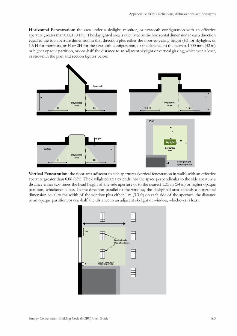
Appendix A: ECBC Definitions, Abbreviations and Acronyms
Energy Conservation Building Code (ECBC) User Guide A.3
Horizontal Fenestration: the area under a skylight, monitor, or sawtooth configuration with an effective aperture greater than 0.001 (0.1%). The daylighted area is calculated as the horizontal dimension in each direction equal to the top aperture dimension in that direction plus either the floor-to-ceiling height (H) for skylights, or 1.5 H for monitors, or H or 2H for the sawtooth configuration, or the distance to the nearest 1000 mm (42 in) or higher opaque partition, or one-half the distance to an adjacent skylight or vertical glazing, whichever is least, as shown in the plan and section figures below.
Vertical Fenestration: the floor area adjacent to side apertures (vertical fenestration in walls) with an effective aperture greater than 0.06 (6%). The daylighted area extends into the space perpendicular to the side aperture a distance either two times the head height of the side aperture or to the nearest 1.35 m (54 in) or higher opaque partition, whichever is less. In the direction parallel to the window, the daylighted area extends a horizontal dimension equal to the width of the window plus either 1 m (3.3 ft) on each side of the aperture, the distance to an opaque partition, or one-half the distance to an adjacent skylight or window, whichever is least.
Appendix A: ECBC Definitions, Abbreviations and Acronyms
Energy Conservation Building Code (ECBC) User Guide A.4
Dead band: the range of values within which a sensed variable can vary without initiating a change in the controlled process
Demand: the highest amount of power (average KW over an interval) recorded for a building or facility in a selected time frame
Design capacity: output capacity of a system or piece of equipment at design conditions
Design conditions: specified environmental conditions, such as temperature and light intensity, required to be produced and maintained by a system and under which the system must operate
Distribution system: a device or group of devices or other means by which the conductors of a circuit can be disconnected from their source of supply
Door: all operable opening areas (which are not fenestration) in the building envelope, including swinging and roll-up doors, fire doors, and access hatches. Doors that are more than one-half glass are considered fenestration. For the purposes of determining building envelope requirements, the classifications are defined as follows:
Door, non-swinging: roll-up sliding, and all other doors that are not swinging doors.
Door, swinging: all operable opaque panels with hinges on one side and opaque revolving doors.
Door area: total area of the door measured using the rough opening and including the door slab and the frame.
Dwelling unit: a single unit providing complete independent living facilities for one or more persons, including permanent provisions for living, sleeping, eating, cooking, and sanitation
Economizer, air: a duct and damper arrangement and automatic control system that together allow a cooling system to supply outdoor air to reduce or eliminate the need for mechanical cooling during mild or cold weather
Economizer, water: a system by which the supply air of a cooling system is cooled indirectly with water that is itself cooled by heat or mass transfer to the environment without the use of mechanical cooling
Effective aperture: Visible Light Transmittance X Window-to-wall Ratio. (EA = VLT X WWR)
Effective aperture, horizontal fenestration: a measure of the amount of daylight that enters a space through horizontal fenestration (skylights). It is the ratio of the skylight area times the visible light transmission divided by the gross roof area above the daylighted area. (See also daylighted area.)
Effective aperture, vertical fenestration: a measure of the amount of daylight that enters a space through vertical fenestration. It is the ratio of the daylight window area times its visible light transmission plus half the vision glass area times its visible light transmission and the sum is divided by the gross wall area. Daylighted window area is located 2.2 m (7 ft) or more above the floor and vision window area is located above 1 m (3 ft) but below 2.2 m (7 ft). The window area, for the purposes of determining effective aperture shall not include windows located in light wells when the angle of obstruction (α) of objects obscuring the sky dome is greater than 70o, measured from the horizontal, nor shall it include window area located below a height of 1 m (3 ft). (See also daylighted area.)
Efficacy: the lumens produced by a lamp/ballast system divided by the total watts of input power (including the ballast), expressed in lumens per watt
Efficiency: performance at a specified rating condition
Remittance: the ratio of the radiant heat flux emitted by a specimen to that emitted by a blackbody at the same temperature and under the same conditions
Enclosed building: a building that is totally enclosed by walls, floors, roofs, and openable devices such as doors and operable windows
Appendix A: ECBC Definitions, Abbreviations and Acronyms
Energy Conservation Building Code (ECBC) User Guide A.5
Energy: the capacity for doing work. It takes a number of forms that may be transformed from one into another such as thermal (heat), mechanical (work), electrical, and chemical. Customary measurements are watts (W)
Energy Efficiency Ratio (EER): performance of smaller chillers and rooftop units is frequently measured in EER rather than 1/η (kW/ton). It is the ratio of net cooling capacity in Btu/h to total rate of electric input in watts under designated operating conditions. The higher the EER, the more efficient the unit
Energy Factor (EF): a measure of water heater overall efficiency
Envelope performance factor: the trade-off value for the building envelope performance compliance option calculated using the procedures specified in Section 12-Appendix D. For the purposes of determining building envelope requirements the classifications are defined as follows:
Base envelope performance factor: the building envelope performance factor for the base design
Proposed envelope performance factor: the building envelope performance factor for the Proposed Design
Equipment: devices for comfort conditioned, electric power, lighting, transportation, or service water heating including, but not limited to, furnaces, boilers, air conditioners, heat pumps, chillers, water heaters, lamps, luminaries, ballasts, elevators, escalators, or other devices or installations
Equipment, existing: equipment previously installed in an existing building
Façade area: area of the façade, including overhanging soffits, cornices, and protruding columns, measured in elevation in a vertical plane, parallel to the plane of the face of the building. Non-horizontal roof surfaces shall be included in the calculations of vertical façade area by measuring the area in a plane parallel to the surface.
Fan system power: the sum of the nominal power demand (nameplate W or HP) of motors of all fans that are required to operate at design conditions to supply air from the heating or cooling source to the conditioned space(s) and return it to the source of exhaust it to the outdoors.
Fenestration: all areas (including the frames) in the building envelope that let in light, including windows, plastic panels, clerestories, skylights, glass doors that are more than one-half glass, and glass block walls.
Skylight: a fenestration surface having a slope of less than 60 degrees from the horizontal plane. Other fenestration, even if mounted on the roof of a building, is considered vertical fenestration.
Fenestration area: total area of the fenestration measured using the rough opening and including the glazing, sash, and frame. For doors where the glazed vision area is less than 50% of the door area, the fenestration area is the glazed vision area. For all other doors, the fenestration area is the door area.
Floor area gross: the sum of the floor areas of the spaces within the building including basements, mezzanine and intermediate-floored tiers, and penthouses with headroom height of 2.5 m (7.5 ft) or greater. It is measured from the exterior faces of exterior walls or from the centerline of walls separating buildings, but excluding covered walkways, open roofed-over areas, porches and similar spaces, pipe trenches, exterior terraces or steps, chimneys, roof overhangs, and similar features.
Gross building envelope floor area: the gross floor area of the building envelope, but excluding slab-on-grade floors.
Gross conditioned floor area: the gross floor area of conditioned spaces.
Gross lighted floor area: the gross floor area of lighted spaces.
Gross semi heated floor area: the gross floor area of semi heated spaces.
Flue damper: a device in the flue outlet or in the inlet of or upstream of the draft control device of an individual, automatically operated, fossil fuel-fired appliance that is designed to automatically open the flue outlet during appliance operation and to automatically close the flue outlet when then appliance is in standby condition.
Appendix A: ECBC Definitions, Abbreviations and Acronyms
Energy Conservation Building Code (ECBC) User Guide A.6
Fossil fuel: fuel derived from a hydrocarbon deposit such as petroleum, coal, or natural gas derived from living matter of a previous geologic time.
Fuel: a material that may be used to produce heat or generate power by combustion.
Generally accepted engineer standard: a specification, rule, guide, or procedure in the field of engineering, or related thereto, recognized and accepted as authoritative.
Grade: the finished ground level adjoining a building at all exterior walls.
Guest room: any room or rooms used or intended to be used by a guest for sleeping purposes.
Heat capacity: the amount of heat necessary to raise the temperature of a given mass 1°C (1°F). Numerically, the heat capacity per unit area of surface (W/m2·K [Btu/ft2-°F]) is the sum of the products of the mass per unit area of each individual material in the roof, wall, or floor surface multiplied by its individual specific heat.
Heat Pump: A heat pump consists of one or more factory-made assemblies that normally include indoor conditioning coil, compressor, and outdoor coil, including means to provide a heating function. Heat pumps provide the function of air heating with controlled temperature, and may include the functions of air cooling, air circulation, air cleaning, dehumidifying, or humidifying.
Heating Seasonal Performance Factor (HSPF): the total heating output of a heat pump during its normal annual usage period for heating (in Btu) divided by the total electric energy input during the same period.
Historic: a building or space that has been specifically designed as historically significant.
HVAC system: the equipment, distribution systems, and terminals that provide, either collectively or individually, the processes of heating, ventilating, or air conditioned to a building or portion of a building.
Infiltration: the uncontrolled inward air leakage through cracks and crevices in any building element and around windows and doors of a building caused by pressure differences across these elements due to factors such as wind, inside and outside temperature differences (stack effect), and imbalance between supply and exhaust air systems.
Installed interior lighting power: the power in watts of all permanently installed general, task, and furniture lighting systems and luminaires.
Integrated part-load value: a single number figure of merit based on part-load EER, COP, or 1/η (kW/ton) expressing part-load efficiency for air-conditioning and heat pump equipment on the basis of weighted operation at various load capacities for the equipment.
Kilovolt-ampere: where the term “kilovolt-ampere” (kVA) is used in this Code, it is the product of the line current (amperes) times the nominal system voltage (kilovolts) times 1.732 for three-phase currents. For single-phase applications, kVA is the product of the line current (amperes) times the nominal system voltage (kilovolts).
Kilowatt: the basic unit of electric power, equal to 1000 W.
Labeled: equipment or materials to which a symbol or other identifying mark has been attached by the manufacturer indicating compliance with specified standard or performance in a specified manner.
Lamp: a generic term for man-made light source often called bulb or tube.
Lighted floor area, gross: the gross floor area of lighted spaces.
Lighting, decorative: lighting that is purely ornamental and installed for aesthetic effect. Decorative lighting shall not include general lighting.
Lighting, emergency: lighting that provides illumination only when there is a general lighting failure.
Lighting, general: lighting that provides a substantially uniform level of illumination throughout an area.
Appendix A: ECBC Definitions, Abbreviations and Acronyms
Energy Conservation Building Code (ECBC) User Guide A.7
General lighting shall not include decorative lighting or lighting that provides a dissimilar level of illumination to serve a specialized application or feature within such area.
Lighting Efficacy (LE): the quotient of the total lumens emitted from a lamp or lamp/ballast combination divided by the watts of input power, expressed in lumens per watt.
Lighting system: a group of luminaires circuited or controlled to perform a specific function.
Lighting power allowance:
Interior lighting power allowance: the maximum lighting power in watts allowed for the interior of a building
Exterior lighting power allowance: the maximum lighting power in watts allowed for the exterior of a building
Lighting Power Density (LPD): the maximum lighting power per unit of area of a building classification of space function.
Low-rise residential: single-family houses, multi-family structures of three stories or fewer above grade, manufactured houses (mobile homes), and manufactured houses (modular).
Lumen: It is the unit of total light output from a light source. If a lamp or fixture were surrounded by a transparent bubble, the total light flow through the bubble is measured in lumens. Lamps are rated in lumens, which is the total amount of light they emit, not their brightness and not the light level on a surface. Typical indoor lamps have light output ranging from 50 to 10,000 lumens. Lumen value is used for purchasing and comparing lamps and their outputs. Lumen output of a lamp is not related to the light distribution pattern of a lamp.
Luminaries: a complete lighting unit consisting of a lamp or lamps together with the housing designed to distribute the light, position and protect the lamps, and connect the lamps to the power supply.
Manual (non-automatic): requiring personal intervention for control. Non-automatic does not necessarily imply a manual controller, only that personal intervention is necessary.
Manufacturer: the company engaged in the original production and assembly of products or equipment or a company that purchases such products and equipment manufactured in accordance with company specifications.
Mean temperature: one-half the sum of the minimum daily temperature and maximum daily temperature.
Mechanical cooling: reducing the temperature of a gas or liquid by using vapor compression, absorption, and desiccant dehumidification combined with evaporative cooling, or another energy-driven thermodynamic cycle. Indirect of direct evaporative cooling alone is not considered mechanical cooling.
Metering: instruments that measure electric voltage, current, power, etc.
Multifamily high-rise: multifamily structures of four or more stories above grade
Multifamily low-rise: multifamily structures of three or less stories above grade
Multiplication factor: indicates the relative reduction in annual solar cooling load from overhangs and/or side fins with given projection factors, relative to the respective horizontal and vertical fenestration dimensions.
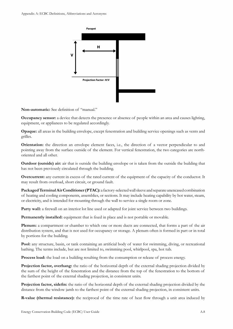
Appendix A: ECBC Definitions, Abbreviations and Acronyms
Energy Conservation Building Code (ECBC) User Guide A.8
Non-automatic: See definition of “manual.”
Occupancy sensor: a device that detects the presence or absence of people within an area and causes lighting, equipment, or appliances to be regulated accordingly.
Opaque: all areas in the building envelope, except fenestration and building service openings such as vents and grilles.
Orientation: the direction an envelope element faces, i.e., the direction of a vector perpendicular to and pointing away from the surface outside of the element. For vertical fenestration, the two categories are north-oriented and all other.
Outdoor (outside) air: air that is outside the building envelope or is taken from the outside the building that has not been previously circulated through the building.
Overcurrent: any current in excess of the rated current of the equipment of the capacity of the conductor. It may result from overload, short circuit, or ground fault.
Packaged Terminal Air Conditioner (PTAC): a factory-selected wall sleeve and separate unencased combination of heating and cooling components, assemblies, or sections. It may include heating capability by hot water, steam, or electricity, and is intended for mounting through the wall to service a single room or zone.
Party wall: a firewall on an interior lot line used or adapted for joint service between two buildings.
Permanently installed: equipment that is fixed in place and is not portable or movable.
Plenum: a compartment or chamber to which one or more ducts are connected, that forms a part of the air distribution system, and that is not used for occupancy or storage. A plenum often is formed in part or in total by portions for the building.
Pool: any structure, basin, or tank containing an artificial body of water for swimming, diving, or recreational bathing. The terms include, but are not limited to, swimming pool, whirlpool, spa, hot tub.
Process load: the load on a building resulting from the consumption or release of process energy.
Projection factor, overhang: the ratio of the horizontal depth of the external shading projection divided by the sum of the height of the fenestration and the distance from the top of the fenestration to the bottom of the farthest point of the external shading projection, in consistent units.
Projection factor, sidefin: the ratio of the horizontal depth of the external shading projection divided by the distance from the window jamb to the farthest point of the external shading projection, in consistent units.
R-value (thermal resistance): the reciprocal of the time rate of heat flow through a unit area induced by
Appendix A: ECBC Definitions, Abbreviations and Acronyms
Energy Conservation Building Code (ECBC) User Guide A.9
a unit temperature difference between two defined surfaces of material or construction under steady-state conditions. Units of R are m2·K/W (h·ft2·°F/Btu). For the prescriptive building envelope option, R-value is for the insulation alone and does not include building materials or air films.
Readily accessible: capable of being reached quickly for operation, renewal, or inspections without requiring those to whom ready access is requisite to climb over or remove obstacles or to resort to portable ladders, chairs, etc. In public facilities, accessibility may be limited to certified personnel through locking covers or by placing equipment in locked rooms.
Recirculating system: a domestic or service hot water distribution system that includes a close circulation circuit designed to maintain usage temperatures in hot water pipes near terminal devices (e.g., lavatory faucets, shower heads) in order to reduce the time required to obtain hot water when the terminal device valve is opened. The motive force for circulation is either natural (due to water density variations with temperature) or mechanical (recirculation pump).
Reflectance: the ratio of the light reflected by a surface to the light incident upon it
Resistance, electric: the property of an electric circuit or of any object used as part of an electric circuit that determines for a given circuit the rate at which electric energy is converted into heat or radiant energy and that has a value such that the product of the resistance and the square of the current gives the rate of conversion of energy
Reset: automatic adjustment of the controller set point to a higher or lower value
Residential: spaces in buildings used primarily for living and sleeping. Residential spaces include, but are not limited to, dwelling units, hotel/motel guest rooms, dormitories, nursing homes, patient rooms in hospitals, lodging houses, fraternity/sorority houses, hostels, prisons, and fire stations.
Return Air: air from the conditioned area that is returned to the conditioning equipment for reconditioning. The air may return to the system through a series of ducts, plenums, and airshafts.
Roof: the upper portion of the building envelope, including opaque areas and fenestration, that is horizontal or tilted at an angle of less than 60° from horizontal
Roof area, gross: the area of the roof measured from the exterior faces of walls or from the centerline of party walls
Service: the equipment for delivering energy from the supply or distribution system to the premises served
Service water heating: heating water for domestic or commercial purposes other than space heating and process requirements
Set point: point at which the desired temperature (°C) of the heated or cooled space is set
Shading Coefficient (SC): the ratio of solar heat gain at normal incidence through glazing to that occurring through 3 mm (1/8 in) thick clear, double-strength glass. Shading coefficient, as used herein, does not include interior, exterior, or integral shading devices
Simulation program: a computer program that is capable of simulating the energy performance of building systems
Single-zone system: an HVAC system serving a single HVAC zone
Site-recovered energy: waste energy recovered at the building site that is used to offset consumption of purchased fuel or electrical energy supplies
Skylight roof ratio (SRR): the ratio of the total skylight area of the roof, measured to the outside of the frame, to the gross exterior roof.
Appendix A: ECBC Definitions, Abbreviations and Acronyms
Energy Conservation Building Code (ECBC) User Guide A.10
Slab-on-grade floor: that portion of a slab floor of the building envelope that is in contact with ground and that is either above grade or is less than or equal to 24 in below the final elevation of the nearest exterior grade
Solar energy source: source of thermal, chemical, or electrical energy derived from direction conversion of incident solar radiation at the building site.
Solar Heat Gain Coefficient (SHGC): the ratio of the solar heat gain entering the space through the fenestration area to the incident solar radiation, typically ranging from 0.9 to 0.1, where lower values indicate lower solar gain. Solar heat gain includes directly transmitted solar heat and absorbed solar radiation, which is then reradiated, conducted, or convected into the space.
Space: an enclosed space within a building. The classifications of spaces are as follows for the purpose of determining building envelope requirements.
Conditioned space: a cooled space, heated space, or directly conditioned space.
Semi-heated space: an enclosed space within a building that is heated by a heating system whose output capacity is greater or equal to 10.7 W/m2 (3.4 Btu/h-ft2) of floor area but is not a conditioned space.
Enclosed Space: space within a building that is not conditioned space or a semi-heated space. Crawlspaces, attics, and parking garages with natural or mechanical ventilation are not considered enclosed spaces.
Standard Design: a computer representation of a hypothetical design based on the actual Proposed Design as per Appendix B– Whole Building Performance Method
Story: portion of a building that is between one finished floor level and the next higher finished floor level or the roof, provided, however, that a basement or cellar shall not be considered a story.
Supply Air: air being conveyed to a conditioned area through ducts or plenums from a heat exchanger of a heating, cooling, absorption, or evaporative cooling system. Supply air is commonly considered air delivered to a space by a space-conditioning system. Depending on space requirements, the supply may be either heated, cooled or neutral.
System: a combination of equipment and auxiliary devices (e.g., controls, accessories, interconnecting means, and terminal elements) by which energy is transformed so it performs a specific function such as HVAC, service water heating, or lighting.
System, existing: a system or systems previously installed in an existing building.
Terminal: a device by which energy form a system is finally delivered, e.g., registers, diffusers, lighting fixtures, faucets, etc.
Thermal block: a collection of one or more HVAC zones grouped together for simulation purposes. Spaces need not be contiguous to be combined within a single thermal block.
Thermal Zone: a term used in energy simulation to represent area catered to by one air conditioning unit. With the help of the “zoning” building plans are simplified to reduce the modeler’s work. Normally, within one zone usage pattern, set point temperature and other conditions are identical. Building spaces that would experience similar heating and cooling loads are generally grouped under one zone.
Thermostat: an automatic control device used to maintain temperature at a fixed or adjustable set point.
Tinted: (as applied to fenestration) bronze, green, or grey coloring that is integral with the glazing material. Tinting does not include surface applied films such as reflective coatings, applied either in the field or during the manufacturing process.
Ton: one ton of cooling is the amount of heat absorbed by one ton of ice melting in one day, which is equivalent to 3.5136 KW or 3.516 thermal kW.
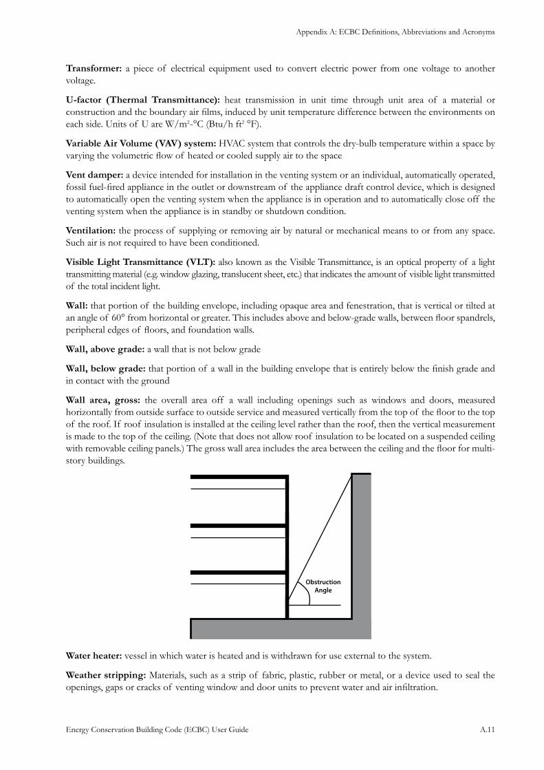
Appendix A: ECBC Definitions, Abbreviations and Acronyms
Energy Conservation Building Code (ECBC) User Guide A.11
Transformer: a piece of electrical equipment used to convert electric power from one voltage to another voltage.
U-factor (Thermal Transmittance): heat transmission in unit time through unit area of a material or construction and the boundary air films, induced by unit temperature difference between the environments on each side. Units of U are W/m2-°C (Btu/h ft2 °F).
Variable Air Volume (VAV) system: HVAC system that controls the dry-bulb temperature within a space by varying the volumetric flow of heated or cooled supply air to the space
Vent damper: a device intended for installation in the venting system or an individual, automatically operated, fossil fuel-fired appliance in the outlet or downstream of the appliance draft control device, which is designed to automatically open the venting system when the appliance is in operation and to automatically close off the venting system when the appliance is in standby or shutdown condition.
Ventilation: the process of supplying or removing air by natural or mechanical means to or from any space. Such air is not required to have been conditioned.
Visible Light Transmittance (VLT): also known as the Visible Transmittance, is an optical property of a light transmitting material (e.g. window glazing, translucent sheet, etc.) that indicates the amount of visible light transmitted of the total incident light.
Wall: that portion of the building envelope, including opaque area and fenestration, that is vertical or tilted at an angle of 60° from horizontal or greater. This includes above and below-grade walls, between floor spandrels, peripheral edges of floors, and foundation walls.
Wall, above grade: a wall that is not below grade
Wall, below grade: that portion of a wall in the building envelope that is entirely below the finish grade and in contact with the ground
Wall area, gross: the overall area off a wall including openings such as windows and doors, measured horizontally from outside surface to outside service and measured vertically from the top of the floor to the top of the roof. If roof insulation is installed at the ceiling level rather than the roof, then the vertical measurement is made to the top of the ceiling. (Note that does not allow roof insulation to be located on a suspended ceiling with removable ceiling panels.) The gross wall area includes the area between the ceiling and the floor for multi-story buildings.
Water heater: vessel in which water is heated and is withdrawn for use external to the system.
Weather stripping: Materials, such as a strip of fabric, plastic, rubber or metal, or a device used to seal the openings, gaps or cracks of venting window and door units to prevent water and air infiltration.
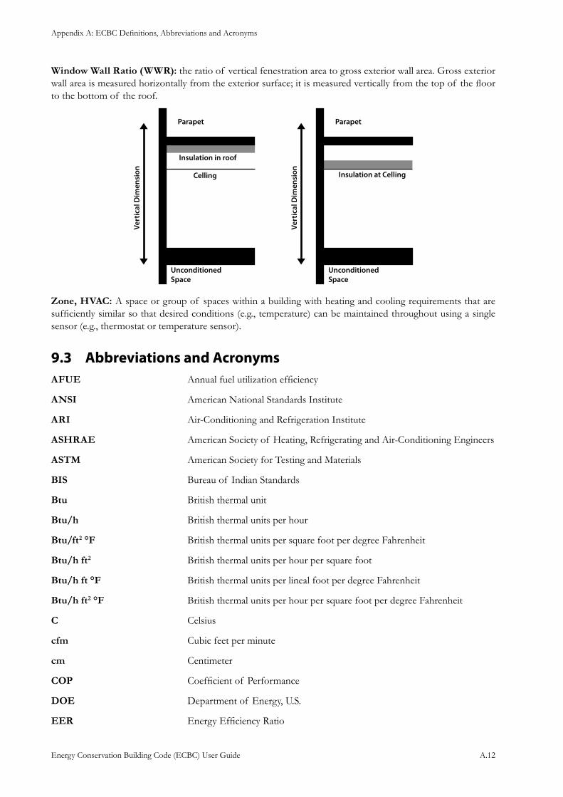
Appendix A: ECBC Definitions, Abbreviations and Acronyms
Energy Conservation Building Code (ECBC) User Guide A.12
Window Wall Ratio (WWR): the ratio of vertical fenestration area to gross exterior wall area. Gross exterior wall area is measured horizontally from the exterior surface; it is measured vertically from the top of the floor to the bottom of the roof.
Zone, HVAC: A space or group of spaces within a building with heating and cooling requirements that are sufficiently similar so that desired conditions (e.g., temperature) can be maintained throughout using a single sensor (e.g., thermostat or temperature sensor).
Abbreviations and Acronyms9.3 AFUE Annual fuel utilization efficiency
ANSI American National Standards Institute
ARI Air-Conditioning and Refrigeration Institute
ASHRAE American Society of Heating, Refrigerating and Air-Conditioning Engineers
ASTM American Society for Testing and Materials
BIS Bureau of Indian Standards
Btu British thermal unit
Btu/h British thermal units per hour
Btu/ft2 °F British thermal units per square foot per degree Fahrenheit
Btu/h ft2 British thermal units per hour per square foot
Btu/h ft °F British thermal units per lineal foot per degree Fahrenheit
Btu/h ft2 °F British thermal units per hour per square foot per degree Fahrenheit
C Celsius
cfm Cubic feet per minute
cm Centimeter
COP Coefficient of Performance
DOE Department of Energy, U.S.
EER Energy Efficiency Ratio
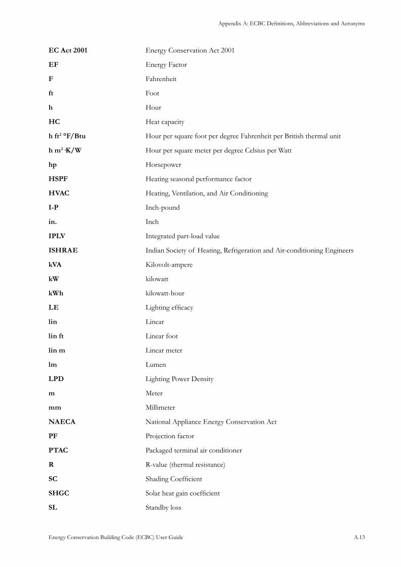
Appendix A: ECBC Definitions, Abbreviations and Acronyms
Energy Conservation Building Code (ECBC) User Guide A.13
EC Act 2001 Energy Conservation Act 2001
EF Energy Factor
F Fahrenheit
ft Foot
h Hour
HC Heat capacity
h ft2 °F/Btu Hour per square foot per degree Fahrenheit per British thermal unit
h m2·K/W Hour per square meter per degree Celsius per Watt
hp Horsepower
HSPF Heating seasonal performance factor
HVAC Heating, Ventilation, and Air Conditioning
I-P Inch-pound
in. Inch
IPLV Integrated part-load value
ISHRAE Indian Society of Heating, Refrigeration and Air-conditioning Engineers
kVA Kilovolt-ampere
kW kilowatt
kWh kilowatt-hour
LE Lighting efficacy
lin Linear
lin ft Linear foot
lin m Linear meter
lm Lumen
LPD Lighting Power Density
m Meter
mm Millimeter
NAECA National Appliance Energy Conservation Act
PF Projection factor
PTAC Packaged terminal air conditioner
R R-value (thermal resistance)
SC Shading Coefficient
SHGC Solar heat gain coefficient
SL Standby loss
Appendix A: ECBC Definitions, Abbreviations and Acronyms
Energy Conservation Building Code (ECBC) User Guide A.14
VAV Variable air volume
VLT Visible light transmission
W Watt
W/ft2 Watts per square feet
W/m2 Watts per square meter
W/m2·K Watts per square meter per degree Celsius
W/m2 Watts per hour per square meter
W/m·K Watts per lineal meter per degree Celsius
W/m2·K Watts per hour per square meter per degree Celsius
Wh Watthour
Appendix B: Whole Building Performance Method
Energy Conservation Building Code (ECBC) User Guide B.1
APPENDIX B: Whole Building Performance Method1
General10.1
Whole building energy simulation analysis is used to predict the annual energy performance of a building design. The analysis is carried out by first developing a detailed building energy simulation model. The
simulation program is then used to test the thermal response, and to calculate the energy use of the building model using a weather data file to capture the climatic impact on the building. This type of analysis is referred to as the “Whole Building Performance” (WBP) method.
Benefits
Whole building energy simulation is currently the most sophisticated way of analyzing the impact of energy efficiency measures in an integrated manner. It is an alternative to the prescriptive requirements contained in §4 to §8 of ECBC. The impact of changing any one of the myriad parameters affecting energy performance of the building design being modeled can be predicted using this method. This is particularly useful for studying the impact of combinations of energy efficiency measures that may lead to non-linear building energy outcomes.
For example, electric lights produce light and heat inside a space. Calculating the electrical consumption for the electric lights is not very difficult, as long as one knows how many lights there are, what their heat output is, and how many hours they run. One does not need a simulation model to predict this outcome. However, the heat generated by electric lighting has to be removed by the HVAC systems in a warm or hot climate. Calculating the reduction in energy used by the HVAC systems due to the use of a more efficient electric lighting system is not recommended through manual calculations.
This computation becomes significantly more complex if the design team decides to employ a daylight linked electric lighting system. Such a system is designed to reduce light (and heat output) in a space when enough daylight is available. This non-linear relationship impacts the electric energy input to the lighting system, and the heat removed by the HVAC system. At this time, predicting the integrated energy performance resulting from complex energy efficiency strategies cannot be studied reliably by any other means except the use of a whole building energy simulation analysis.
Once the model is completed and a base run is established, carrying out multiple runs to test alternate design options involves less effort on the part of the analyst, although there could still be substantial computer run time involved. Whole building energy simulation is increasingly being used for testing compliance with various building energy codes and sustainability rating tools such as LEED and GRIHA. Technically reliable and verifiable energy simulation programs satisfying the minimum modeling capabilities (specified in §10.2.1) should be used for compliance using this verification method.
Scope10.1.1 In general, the WBP method may be used to show compliance with the ECBC for any project at the designer’s discretion, subject to the following caveats and exceptions.
No HVAC System
Use of the WBP method requires knowledge of the proposed HVAC system in order to create the Standard Design. Buildings with no HVAC system cannot use the WBP Method. In the case of a shell building, which might become conditioned in the future, trade-offs may still be made within the envelope system.
1 This chapter has been adapted from Appendix G and ECB chapter of ASHRAE User Manual
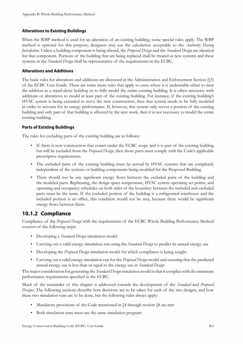
Appendix B: Whole Building Performance Method
Energy Conservation Building Code (ECBC) User Guide B.2
Alterations to Existing Buildings
When the WBP method is used for an alteration of an existing building, some special rules apply. The WBP method is optional for this purpose; designers may use the calculation acceptable to the Authority Having Jurisdiction. Unless a building component is being altered, the Proposed Design and the Standard Design are identical for that component. Portions of the building that are being replaced shall be treated as new systems and these systems in the Standard Design shall be representative of the requirements in the ECBC.
Alterations and Additions
The basic rules for alterations and additions are discussed in the Administration and Enforcement Section (§3) of the ECBC User Guide. There are some more rules that apply to cases where it is undesirable either to treat the addition as a stand-alone building or to fully model the entire existing building. It is often necessary with additions or alterations to model at least part of the existing building. For instance, if the existing building’s HVAC system is being extended to serve the new construction, then that system needs to be fully modeled in order to account for its energy performance. If, however, this system only serves a portion of the existing building and only part of that building is affected by the new work, then it is not necessary to model the entire existing building.
Parts of Existing Buildings
The rules for excluding parts of the existing building are as follows:
If there is new construction that comes under the ECBC scope and it is part of the existing building • but will be excluded from the Proposed Design, then those parts must comply with the Code’s applicable prescriptive requirements.
The excluded parts of the existing building must be served by HVAC systems that are completely • independent of the systems or building components being modeled for the Proposed Building.
There should not be any significant energy flows between the excluded parts of the building and • the modeled parts. Rephrasing, the design space temperature, HVAC system operating set points, and operating and occupancy schedules on both sides of the boundary between the included and excluded parts must be the same. If the excluded portion of the building is a refrigerated warehouse and the included portion is an office, this condition would not be met, because there would be significant energy flows between them.
Compliance 10.1.2 Compliance of the Proposed Design with the requirements of the ECBC Whole Building Performance Method consists of the following steps:
Developing a • Standard Design simulation model
Carrying out a valid energy simulation run using the • Standard Design to predict its annual energy use
Developing the • Proposed Design simulation model for which compliance is being sought
Carrying out a valid energy simulation run for the • Proposed Design model and ensuring that the predicted annual energy use is less than or equal to the energy use in Standard Design
The major consideration for generating the Standard Design simulation model is that it complies with the minimum performance requirements specified in the ECBC.
Much of the remainder of this chapter is addressed towards the development of the Standard and Proposed Designs. The following sections describe how decisions are to be taken for each of the two designs, and how these two simulation runs are to be done, but the following rules always apply:
Mandatory provisions of the Code mentioned in §4 through section §8 are met•
Both simulation runs must use the same simulation program•
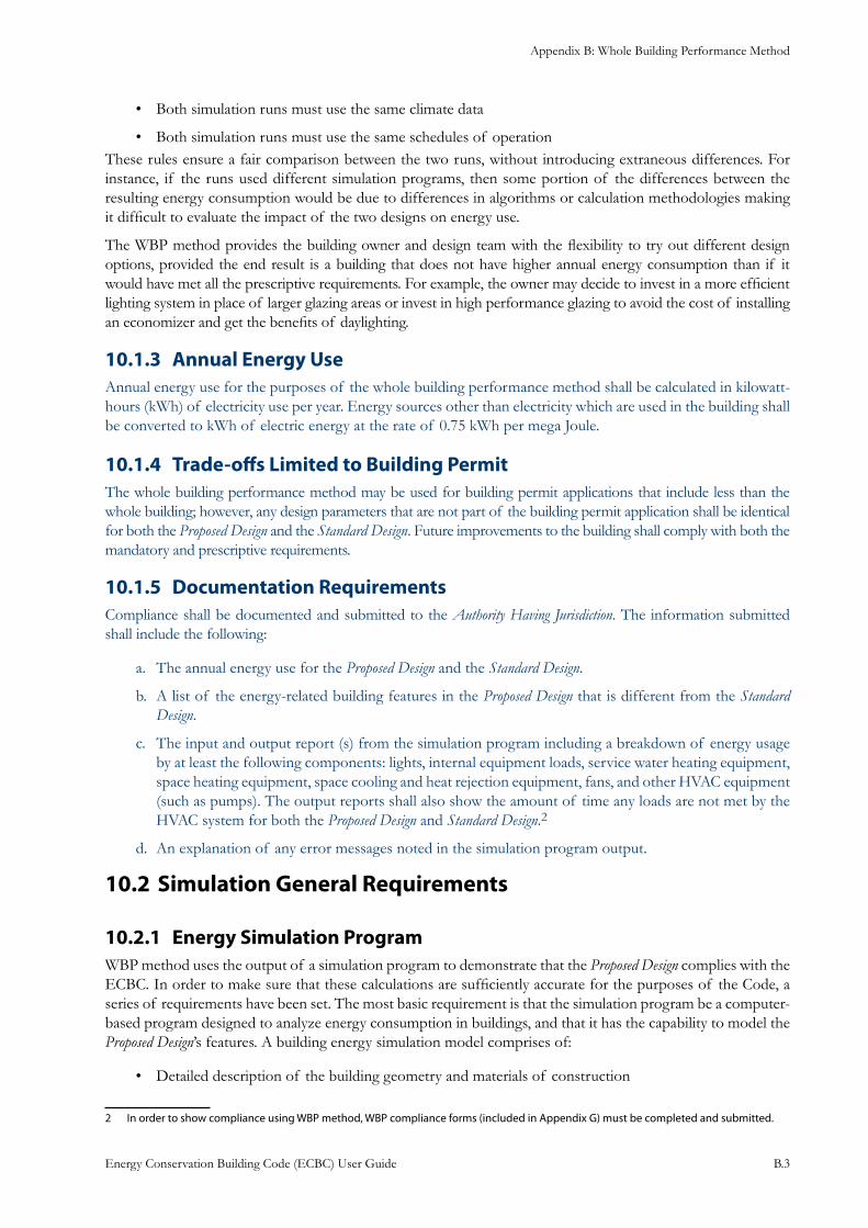
Appendix B: Whole Building Performance Method
Energy Conservation Building Code (ECBC) User Guide B.3
Both simulation runs must use the same climate data•
Both simulation runs must use the same schedules of operation• These rules ensure a fair comparison between the two runs, without introducing extraneous differences. For instance, if the runs used different simulation programs, then some portion of the differences between the resulting energy consumption would be due to differences in algorithms or calculation methodologies making it difficult to evaluate the impact of the two designs on energy use.
The WBP method provides the building owner and design team with the flexibility to try out different design options, provided the end result is a building that does not have higher annual energy consumption than if it would have met all the prescriptive requirements. For example, the owner may decide to invest in a more efficient lighting system in place of larger glazing areas or invest in high performance glazing to avoid the cost of installing an economizer and get the benefits of daylighting.
Annual Energy Use10.1.3 Annual energy use for the purposes of the whole building performance method shall be calculated in kilowatt-hours (kWh) of electricity use per year. Energy sources other than electricity which are used in the building shall be converted to kWh of electric energy at the rate of 0.75 kWh per mega Joule.
Trade-offs Limited to Building Permit10.1.4 The whole building performance method may be used for building permit applications that include less than the whole building; however, any design parameters that are not part of the building permit application shall be identical for both the Proposed Design and the Standard Design. Future improvements to the building shall comply with both the mandatory and prescriptive requirements.
Documentation Requirements10.1.5 Compliance shall be documented and submitted to the Authority Having Jurisdiction. The information submitted shall include the following:
The annual energy use for the a. Proposed Design and the Standard Design.
A list of the energy-related building features in the b. Proposed Design that is different from the Standard Design.
The input and output report (s) from the simulation program including a breakdown of energy usage c. by at least the following components: lights, internal equipment loads, service water heating equipment, space heating equipment, space cooling and heat rejection equipment, fans, and other HVAC equipment (such as pumps). The output reports shall also show the amount of time any loads are not met by the HVAC system for both the Proposed Design and Standard Design.2
An explanation of any error messages noted in the simulation program output.d.
Simulation General Requirements10.2
Energy Simulation Program10.2.1 WBP method uses the output of a simulation program to demonstrate that the Proposed Design complies with the ECBC. In order to make sure that these calculations are sufficiently accurate for the purposes of the Code, a series of requirements have been set. The most basic requirement is that the simulation program be a computer-based program designed to analyze energy consumption in buildings, and that it has the capability to model the Proposed Design’s features. A building energy simulation model comprises of:
Detailed description of the building geometry and materials of construction•
2 In order to show compliance using WBP method, WBP compliance forms (included in Appendix G) must be completed and submitted.
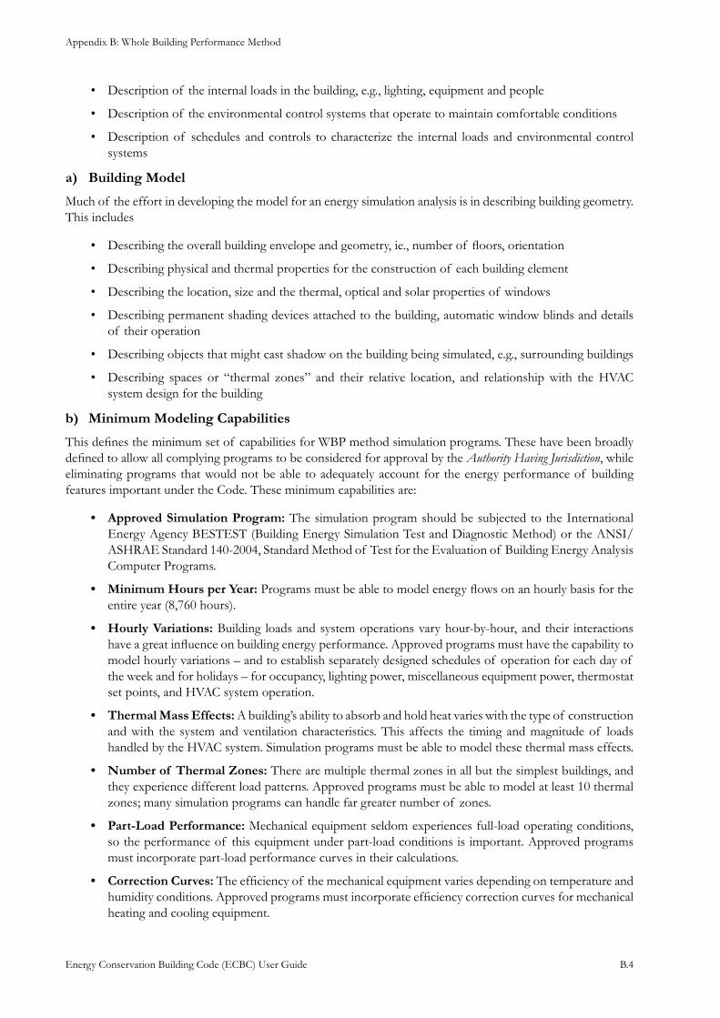
Appendix B: Whole Building Performance Method
Energy Conservation Building Code (ECBC) User Guide B.4
Description of the internal loads in the building, e.g., lighting, equipment and people•
Description of the environmental control systems that operate to maintain comfortable conditions•
Description of schedules and controls to characterize the internal loads and environmental control • systems
Building Modela)
Much of the effort in developing the model for an energy simulation analysis is in describing building geometry. This includes
Describing the overall building envelope and geometry, ie., number of floors, orientation•
Describing physical and thermal properties for the construction of each building element•
Describing the location, size and the thermal, optical and solar properties of windows•
Describing permanent• shading devices attached to the building, automatic window blinds and details of their operation
Describing objects that might cast shadow on the building being simulated, e.g., surrounding buildings•
Describing spaces or “thermal zones” and their relative location, and relationship with the HVAC • system design for the building
Minimum Modeling Capabilitiesb)
This defines the minimum set of capabilities for WBP method simulation programs. These have been broadly defined to allow all complying programs to be considered for approval by the Authority Having Jurisdiction, while eliminating programs that would not be able to adequately account for the energy performance of building features important under the Code. These minimum capabilities are:
Approved Simulation Program:• The simulation program should be subjected to the International Energy Agency BESTEST (Building Energy Simulation Test and Diagnostic Method) or the ANSI/ASHRAE Standard 140-2004, Standard Method of Test for the Evaluation of Building Energy Analysis Computer Programs.
Minimum Hours per Year:• Programs must be able to model energy flows on an hourly basis for the entire year (8,760 hours).
Hourly Variations:• Building loads and system operations vary hour-by-hour, and their interactions have a great influence on building energy performance. Approved programs must have the capability to model hourly variations – and to establish separately designed schedules of operation for each day of the week and for holidays – for occupancy, lighting power, miscellaneous equipment power, thermostat set points, and HVAC system operation.
Thermal Mass Effects:• A building’s ability to absorb and hold heat varies with the type of construction and with the system and ventilation characteristics. This affects the timing and magnitude of loads handled by the HVAC system. Simulation programs must be able to model these thermal mass effects.
Number of Thermal Zones:• There are multiple thermal zones in all but the simplest buildings, and they experience different load patterns. Approved programs must be able to model at least 10 thermal zones; many simulation programs can handle far greater number of zones.
Part-Load Performance:• Mechanical equipment seldom experiences full-load operating conditions, so the performance of this equipment under part-load conditions is important. Approved programs must incorporate part-load performance curves in their calculations.
Correction Curves:• The efficiency of the mechanical equipment varies depending on temperature and humidity conditions. Approved programs must incorporate efficiency correction curves for mechanical heating and cooling equipment.
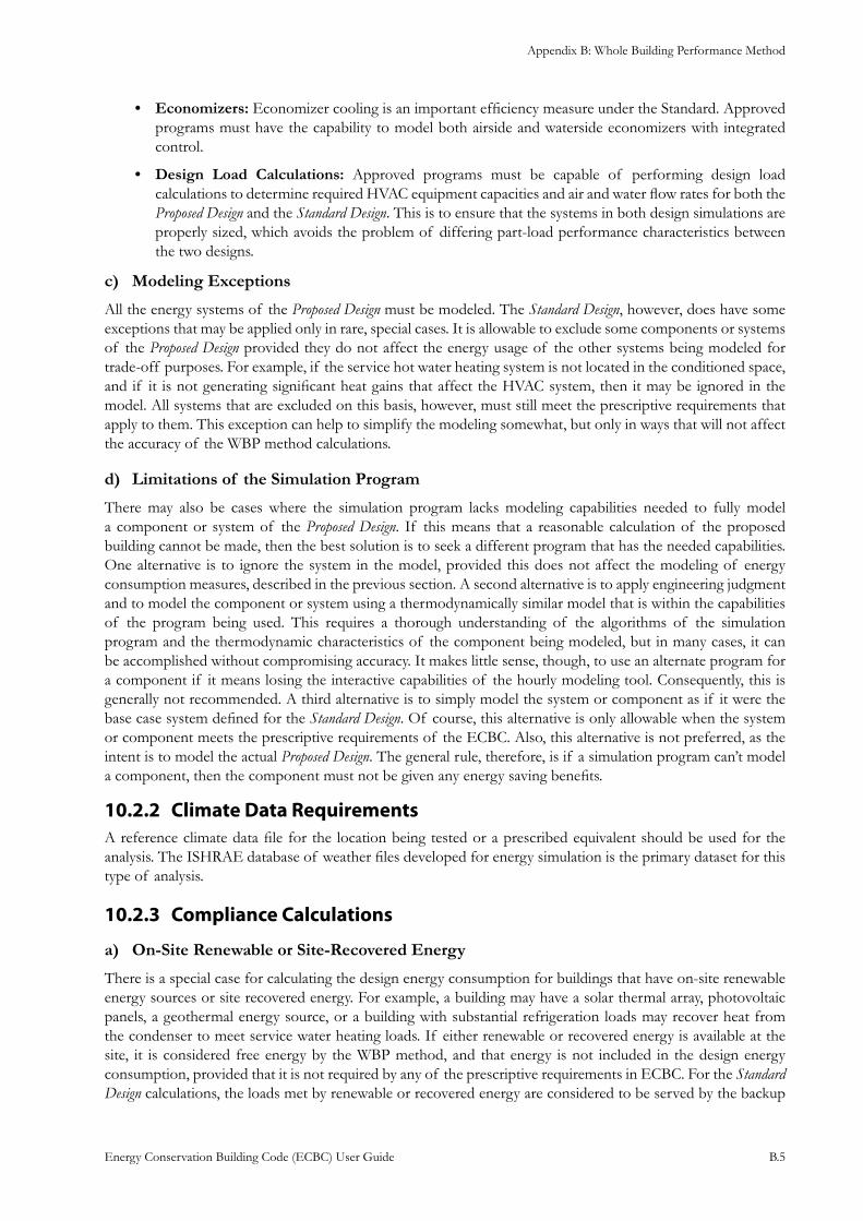
Appendix B: Whole Building Performance Method
Energy Conservation Building Code (ECBC) User Guide B.5
Economizers:• Economizer cooling is an important efficiency measure under the Standard. Approved programs must have the capability to model both airside and waterside economizers with integrated control.
Design Load Calculations:• Approved programs must be capable of performing design load calculations to determine required HVAC equipment capacities and air and water flow rates for both the Proposed Design and the Standard Design. This is to ensure that the systems in both design simulations are properly sized, which avoids the problem of differing part-load performance characteristics between the two designs.
Modeling Exceptions c)
All the energy systems of the Proposed Design must be modeled. The Standard Design, however, does have some exceptions that may be applied only in rare, special cases. It is allowable to exclude some components or systems of the Proposed Design provided they do not affect the energy usage of the other systems being modeled for trade-off purposes. For example, if the service hot water heating system is not located in the conditioned space, and if it is not generating significant heat gains that affect the HVAC system, then it may be ignored in the model. All systems that are excluded on this basis, however, must still meet the prescriptive requirements that apply to them. This exception can help to simplify the modeling somewhat, but only in ways that will not affect the accuracy of the WBP method calculations.
Limitations of the Simulation Programd)
There may also be cases where the simulation program lacks modeling capabilities needed to fully model a component or system of the Proposed Design. If this means that a reasonable calculation of the proposed building cannot be made, then the best solution is to seek a different program that has the needed capabilities. One alternative is to ignore the system in the model, provided this does not affect the modeling of energy consumption measures, described in the previous section. A second alternative is to apply engineering judgment and to model the component or system using a thermodynamically similar model that is within the capabilities of the program being used. This requires a thorough understanding of the algorithms of the simulation program and the thermodynamic characteristics of the component being modeled, but in many cases, it can be accomplished without compromising accuracy. It makes little sense, though, to use an alternate program for a component if it means losing the interactive capabilities of the hourly modeling tool. Consequently, this is generally not recommended. A third alternative is to simply model the system or component as if it were the base case system defined for the Standard Design. Of course, this alternative is only allowable when the system or component meets the prescriptive requirements of the ECBC. Also, this alternative is not preferred, as the intent is to model the actual Proposed Design. The general rule, therefore, is if a simulation program can’t model a component, then the component must not be given any energy saving benefits.
Climate Data Requirements10.2.2 A reference climate data file for the location being tested or a prescribed equivalent should be used for the analysis. The ISHRAE database of weather files developed for energy simulation is the primary dataset for this type of analysis.
Compliance Calculations10.2.3
On-Site Renewable or Site-Recovered Energya)
There is a special case for calculating the design energy consumption for buildings that have on-site renewable energy sources or site recovered energy. For example, a building may have a solar thermal array, photovoltaic panels, a geothermal energy source, or a building with substantial refrigeration loads may recover heat from the condenser to meet service water heating loads. If either renewable or recovered energy is available at the site, it is considered free energy by the WBP method, and that energy is not included in the design energy consumption, provided that it is not required by any of the prescriptive requirements in ECBC. For the Standard Design calculations, the loads met by renewable or recovered energy are considered to be served by the backup
Appendix B: Whole Building Performance Method
Energy Conservation Building Code (ECBC) User Guide B.6
energy source. For example, where recovered energy is used to heat water, then the backup water heater would be assumed to supply all the hot water for the Standard Design, and that would be part of the Standard Design method. If no backup energy source is specified for the Proposed Design, then the source is assumed to be electricity in the Standard Design.
Exceptional Calculation Method b)
As newer technologies become available, there may be cases where none of the existing simulation programs can adequately model the energy performance of these technologies. The WBP method allows users to use exceptional calculations, provided the nature of the exceptional method is open-ended; however, the burden is on the applicant to demonstrate that the method is reasonable, accurate, well founded, and not in contradiction with the rules of the WBP Method. The applicant must describe the theoretical basis for the exceptional method and must provide empirical evidence that the method accurately represents the energy performance of the design, material, or device.
Disclaimer c)
It is important for users of the WBP method, as well as the owners of the proposed buildings, to understand the WBP Method’s intent and limitations. It is intended to provide a fair method of comparison between the estimated annual energy consumption of the Proposed Design and the Standard Design for purposes of compliance with the Code. The WBP Method is not intended to provide the most accurate prediction of actual energy consumption for the building as it is actually built. Although the designer is expected to model the future use of the building as closely as possible, there are many reasons why the actual building performance may differ from the design energy consumption. These include:
Variations in Operation and Occupancy:• The actual schedules of operation and occupancy may differ from those assumed in the WBP analysis.
Variations in Control and Maintenance:• The building’s energy systems may be controlled differently than assumed; the equipment may not be set up or maintained properly.
Variations in Weather:• The simulation runs use weather data that may not match the actual weather conditions; further, there is variability in weather conditions from year-to-year.
Energy Uses not Included:• The WBP method under certain conditions, may not require all building energy uses to be included in calculating the design energy consumption. Sometimes, there is additional energy-using equipment that is added to a building after it is built.
Precision of the Simulation Program:• Even the most sophisticated simulation programs approximate the actual energy flows and consumption in a building; further, the energy analyst will usually make simplifying assumptions. Both can be sources of error in the predictions of energy consumption.
Calculating the Energy Consumption of the 10.3 Proposed Design and the Standard Design
The simulation model for calculating the 10.3.1 Proposed Design and the Standard Design shall be developed in accordance with the require-ments in Table 10.1
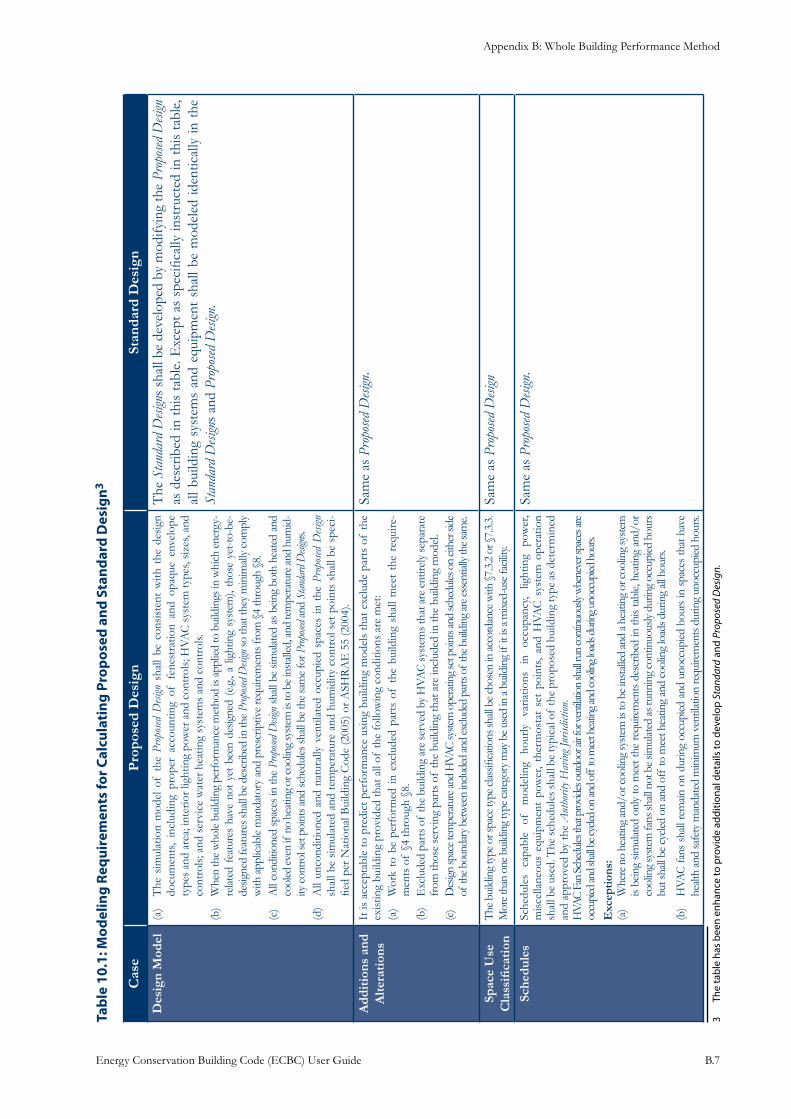
Appendix B: Whole Building Performance Method
Energy Conservation Building Code (ECBC) User Guide B.7
: Mod
elin
g Re
quir
emen
ts fo
r Cal
cula
ting
Pro
pose
d an
d St
anda
rd D
esig
nTa
ble
10.1
3
Cas
eP
ropo
sed
Des
ign
Stan
dard
Des
ign
Des
ign
Mod
elT
he s
imul
atio
n m
odel
of
the
(a)
Prop
osed
Desi
gn s
hall
be c
onsi
sten
t w
ith t
he d
esig
n do
cum
ents
, in
clud
ing
prop
er a
ccou
ntin
g of
fen
estr
atio
n an
d op
aque
env
elop
e ty
pes
and
area
; int
erio
r lig
htin
g po
wer
and
con
trol
s; H
VAC
sys
tem
type
s, si
zes,
and
cont
rols
; and
ser
vice
wat
er h
eatin
g sy
stem
s an
d co
ntro
ls.W
hen
the
who
le b
uild
ing
perf
orm
ance
met
hod
is ap
plie
d to
bui
ldin
gs in
whi
ch e
nerg
y-(b
) re
late
d fe
atur
es h
ave
not
yet
been
des
igne
d (e
.g., a
ligh
ting
syst
em),
thos
e ye
t-to-
be-
desig
ned
feat
ures
shal
l be
desc
ribed
in th
e Pr
opos
ed D
esign
so th
at th
ey m
inim
ally
com
ply
with
app
licab
le m
anda
tory
and
pre
scrip
tive
requ
irem
ents
from
§4
thro
ugh
§8.
All
cond
ition
ed s
pace
s in
the
(c)
Pro
posed
Desi
gn s
hall
be s
imul
ated
as
bein
g bo
th h
eate
d an
d co
oled
even
if n
o he
atin
g or
cool
ing
syst
em is
to b
e ins
talle
d, an
d te
mpe
ratu
re an
d hu
mid
-ity
con
trol s
et p
oint
s and
sche
dules
shall
be
the
sam
e fo
r Pro
posed
and
Sta
ndar
d D
esign
s. A
ll un
cond
ition
ed a
nd n
atur
ally
ven
tilat
ed o
ccup
ied
spac
es in
the
(d
) Pr
opos
ed D
esign
sh
all b
e si
mul
ated
and
tem
pera
ture
and
hum
idity
con
trol
set
poi
nts
shal
l be
spec
i-fie
d pe
r Nat
iona
l Bui
ldin
g C
ode
(200
5) o
r ASH
RA
E 5
5 (2
004)
.
The
Sta
ndar
d D
esign
s sh
all b
e de
velo
ped
by m
odify
ing
the
Prop
osed
Desi
gn
as d
escr
ibed
in t
his
tabl
e. E
xcep
t as
spe
cific
ally
inst
ruct
ed in
thi
s ta
ble,
al
l bui
ldin
g sy
stem
s an
d eq
uipm
ent
shal
l be
mod
eled
iden
tical
ly in
the
St
anda
rd D
esign
s an
d Pr
opos
ed D
esign
.
Add
itio
ns a
nd
Alte
rati
ons
It is
acc
epta
ble
to p
redi
ct p
erfo
rman
ce u
sing
bui
ldin
g m
odel
s th
at e
xclu
de p
arts
of
the
exis
ting
build
ing
prov
ided
that
all
of th
e fo
llow
ing
cond
ition
s ar
e m
et:
Wor
k to
be
perf
orm
ed in
exc
lude
d pa
rts
of t
he b
uild
ing
shal
l mee
t th
e re
quire
-(a
) m
ents
of
§4 th
roug
h §8
.E
xclu
ded
part
s of
the
build
ing
are
serv
ed b
y H
VAC
syst
ems t
hat a
re e
ntire
ly se
para
te
(b)
from
thos
e se
rvin
g pa
rts
of th
e bu
ildin
g th
at a
re in
clud
ed in
the
build
ing
mod
el.
Des
ign sp
ace t
empe
ratu
re an
d H
VAC
syste
m o
pera
ting s
et p
oint
s and
sche
dules
on
eithe
r sid
e (c
) of
the b
ound
ary b
etw
een
inclu
ded
and
exclu
ded
parts
of
the b
uild
ing
are e
ssen
tially
the s
ame.
Sam
e as
Pro
posed
Desi
gn.
Spac
e U
se
Cla
ssifi
cati
onT
he b
uild
ing
type
or s
pace
type
clas
sifica
tions
shall
be
chos
en in
acco
rdan
ce w
ith §
7.3.
2 or
§7.
3.3.
M
ore t
han
one b
uild
ing
type
cate
gory
may
be u
sed
in a
build
ing
if it
is a
mixe
d-us
e fac
ility.
Sam
e as
Pro
posed
Desi
gn
Sche
dule
sSc
hedu
les
capa
ble
of
mod
elin
g ho
urly
va
riatio
ns
in
occu
panc
y, lig
htin
g po
wer
, m
isce
llane
ous
equi
pmen
t po
wer
, th
erm
osta
t se
t po
ints
, an
d H
VAC
sys
tem
ope
ratio
n sh
all b
e us
ed. T
he sc
hedu
les s
hall
be ty
pica
l of
the
prop
osed
bui
ldin
g ty
pe a
s det
erm
ined
an
d ap
prov
ed b
y th
e A
utho
rity H
avin
g Jur
isdict
ion.
HVA
C Fa
n Sc
hedu
les th
at pr
ovid
es o
utdo
or ai
r for
vent
ilatio
n sh
all ru
n co
ntinu
ously
whe
neve
r spa
ces a
re
occu
pied
and
shall
be c
ycled
on
and
off t
o m
eet h
eatin
g and
cool
ing l
oads
dur
ing u
nocc
upied
hou
rs.E
xcep
tion
s:W
here
no
heat
ing
and/
or co
olin
g sy
stem
is to
be i
nsta
lled
and
a hea
ting
or co
olin
g sy
stem
(a
) is
bein
g sim
ulat
ed o
nly
to m
eet t
he re
quire
men
ts d
escr
ibed
in th
is ta
ble,
heat
ing
and/
or
cool
ing
syst
em fa
ns sh
all n
ot b
e sim
ulat
ed as
runn
ing
cont
inuo
usly
durin
g oc
cupi
ed h
ours
bu
t sha
ll be
cyc
led o
n an
d of
f to
mee
t hea
ting
and
cool
ing
load
s dur
ing
all h
ours
.
HVA
C fa
ns s
hall
rem
ain o
n du
ring
occu
pied
and
uno
ccup
ied h
ours
in s
pace
s th
at h
ave
(b)
healt
h an
d sa
fety
man
date
d m
inim
um v
entil
atio
n re
quire
men
ts d
urin
g un
occu
pied
hou
rs.
Sam
e as
Pro
posed
Desi
gn.
3 Th
e ta
ble
has
been
enh
ance
to p
rovi
de a
dditi
onal
det
ails
to d
evel
op S
tand
ard
and
Prop
osed
Des
ign.
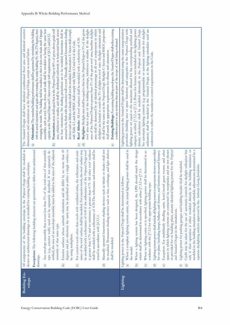
Appendix B: Whole Building Performance Method
Energy Conservation Building Code (ECBC) User Guide B.8
Bui
ldin
g E
n-ve
lope
All
com
pone
nts
of t
he b
uild
ing
enve
lope
in
the
Prop
osed
Desi
gn s
hall
be m
odel
ed a
s sh
own
on a
rchi
tect
ural
dra
win
gs o
r as
inst
alle
d fo
r exi
stin
g bu
ildin
g en
velo
pes.
Exc
epti
ons:
The
follo
win
g bu
ildin
g el
emen
ts a
re p
erm
itted
to d
iffer
from
arc
hite
ctur
al
draw
ings
.
Any
env
elop
e as
sem
bly
that
cov
ers
less
than
5%
of
the
tota
l are
a of
that
ass
embl
y (a
) ty
pe (
e.g.
, ext
erio
r w
alls
) ne
ed n
ot b
e se
para
tely
des
crib
ed. I
f no
t se
para
tely
de-
scrib
ed, t
he a
rea
of a
n en
velo
pe a
ssem
bly
mus
t be
adde
d to
the
area
of
the
adja
cent
as
sem
bly
of th
at s
ame
type
.
Ext
erio
r su
rfac
es w
hose
azi
mut
h or
ient
atio
n an
d til
t di
ffer
by
no m
ore
than
45
(b)
degr
ees
and
are
othe
rwis
e th
e sa
me
may
be
desc
ribed
as
eith
er a
sin
gle
surf
ace
or
by u
sing
mul
tiplie
rs.
For
exte
rior
roof
s ot
her
than
roo
fs w
ith v
entil
ated
atti
cs, t
he r
eflec
tanc
e an
d em
it-(c
) ta
nce
of th
e ro
of su
rfac
e sh
all b
e m
odel
ed. F
or e
xter
ior r
oofs
, the
roof
surf
ace
may
be
mod
eled
with
a re
flect
ance
of
0.45
if th
e re
flect
ance
of
the
Prop
osed
Desi
gn ro
of
is g
reat
er t
han
0.70
and
its
emitt
ance
is g
reat
er t
han
0.75
. All
othe
r ro
of s
urfa
ces
shal
l be
mod
eled
with
a r
eflec
tanc
e of
0.3
0.T
he r
eflec
tanc
e an
d em
ittan
ce s
hall
be
test
ed in
acc
orda
nce
with
§4.
3.1.
1.
Man
ually
ope
rate
d fe
nest
ratio
n sh
adin
g de
vice
s su
ch a
s bl
inds
or
shad
es s
hall
not
(d)
be m
odel
ed. P
erm
anen
t sha
ding
dev
ices
suc
h as
fins
, ove
rhan
gs, a
nd li
ght s
helv
es
shal
l be
mod
eled
.
The
Sta
ndar
d D
esign
s sh
all
have
ide
ntic
al c
ondi
tione
d flo
or a
rea
and
iden
tical
ext
erio
r di
men
sion
s an
d or
ient
atio
ns a
s th
e Pr
opos
ed D
esign
, exc
ept a
s no
ted
belo
w.O
rient
atio
n:(a
) T
he st
anda
rd b
uild
ing p
erfo
rman
ce sh
all b
e gen
erat
ed b
y sim
ulat
ing t
he b
uild
ing
with
its a
ctua
l orie
ntat
ion
and
again
afte
r rot
atin
g th
e ent
ire b
uild
ing
90, 1
80, 2
70 d
egre
es, t
hen
aver
agin
g th
e re
sults
. The
bui
ldin
g sh
all b
e m
odele
d so
that
it d
oes n
ot sh
ade
itself
. Opa
que
asse
mbl
ies s
uch
as r
oof,
floor
s, do
ors,
and
wall
s sh
all b
e m
odele
d as
hav
ing
the
sam
e he
at
capa
city a
s the
Prop
osed D
esign
and
U-fa
ctor
com
ply w
ith re
quire
men
ts of
§4.3.
1 an
d §4
.3.2.
Fene
stra
tion
(b)
area
s sha
ll equ
al th
at in
the P
ropo
sed D
esign
or 4
0% o
f gr
oss a
bove
gra
de w
all
area
, whi
chev
er is
sm
aller
, and
sha
ll be
dist
ribut
ed u
nifo
rmly
in h
oriz
onta
l ban
ds a
cros
s th
e fo
ur o
rient
atio
ns. N
o sh
adin
g pr
ojec
tions
are
to
be m
odele
d; f
enes
tratio
n sh
all b
e as
sum
ed to
be fl
ush
with
the e
xter
ior w
all o
r roo
f. M
anua
lly o
pera
ted
fene
stra
tion
shad
ing
devi
ces s
uch
as b
linds
or s
hade
s sha
ll no
t be
mod
eled.
Fen
estra
tion
U-fa
ctor
shall
com
ply
with
Tab
le 4.
3, a
nd th
e SH
GC
shall
com
ply
with
Tab
le 4.
3 an
d 4.
4 of
the
Cod
e.R
oof
Alb
edo:
(c)
All
roof
sur
face
s sh
all b
e m
odel
ed w
ith a
refle
ctiv
ity o
f 0.
30.
Skyl
ight
s(d
) : S
kylig
ht a
rea
shal
l be
equa
l to
that
in th
e Pr
opos
ed D
esign
or 5
% o
f th
e gr
oss
roof
are
a th
at is
par
t of
the
build
ing
enve
lope
, whi
chev
er is
sm
alle
r. If
the
skyl
ight
ar
ea o
f th
e Pr
opos
ed D
esign
is g
reat
er th
an 5
% o
f th
e gr
oss r
oof
area
, bas
elin
e sk
ylig
ht
area
sha
ll be
dec
reas
ed b
y an
iden
tical
per
cent
age
in a
ll ro
of c
ompo
nent
s in
whi
ch
skyl
ight
s ar
e lo
cate
d to
rea
ch th
e 5%
sky
light
-to-r
oof
ratio
. Sky
light
orie
ntat
ion
and
tilt s
hall
be th
e sa
me
as in
the
Prop
osed
Desi
gn. S
kylig
ht U
-fac
tor a
nd S
HG
C p
rope
rtie
s sh
all m
atch
the
appr
opria
te re
quire
men
ts fo
r clim
ate
and
orie
ntat
ion.
Exi
stin
g B
uild
ings
.(e
) F
or ex
istin
g bui
ldin
g env
elope
s, th
e Stan
dard
Desi
gns s
hall r
eflec
t exi
sting
co
nditi
ons p
rior t
o an
y rev
ision
s tha
t are
par
t of
the s
cope
of
wor
k be
ing
evalu
ated
.
Lig
htin
gLi
ghtin
g po
wer
in th
e Pr
opos
ed D
esign
sha
ll be
det
erm
ined
as
follo
ws:
Whe
re a
com
plet
e lig
htin
g sy
stem
exi
sts,
the
actu
al li
ghtin
g po
wer
sha
ll be
use
d in
(a
) th
e m
odel
.W
here
a l
ight
ing
syst
em h
as b
een
desi
gned
, th
e LP
D s
houl
d m
atch
the
des
ign
(b)
whi
ch s
hall
be d
eter
min
ed in
acc
orda
nce
with
eith
er §
7.3.
2 or
§7.
3.3.
Whe
re n
o lig
htin
g ex
ists
or
is s
peci
fied,
ligh
ting
pow
er s
hall
be d
eter
min
ed in
ac-
(c)
cord
ance
with
the
§7.3
.2 fo
r the
app
ropr
iate
bui
ldin
g ty
pe.
Ligh
ting
syst
em p
ower
shal
l inc
lude
all l
ight
ing
syst
em co
mpo
nent
s sho
wn
or p
rovi
ded
(d)
for o
n pl
ans
(incl
udin
g la
mps
, bal
last
s, ta
sk fi
xtur
es, a
nd fu
rnitu
re-m
ount
ed fi
xtur
es).
Exc
eptio
n: F
or m
ultif
amily
dw
ellin
g un
its,
hote
l/m
otel
gue
st r
oom
s, an
d ot
her
(e)
spac
es in
whi
ch li
ghtin
g sy
stem
s ar
e co
nnec
ted
via
rece
ptac
les
and
are
not s
how
n or
pro
vide
d fo
r on
bui
ldin
g pl
ans,
assu
me
iden
tical
ligh
ting
pow
er f
or th
e Pr
opos
ed
and
Stan
dard
Desi
gns
in th
e si
mul
atio
ns.
Ligh
ting
pow
er fo
r par
king
gar
ages
and
bui
ldin
g fa
cade
s sh
all b
e m
odel
ed.
(f)
Cre
dit
may
be
take
n fo
r th
e us
e of
aut
omat
ic c
ontr
ols
for
dayl
ight
util
izat
ion
but
(g)
only
if
thei
r op
erat
ion
is e
ither
mod
eled
dire
ctly
in
the
build
ing
sim
ulat
ion
or
mod
eled
in th
e bu
ildin
g si
mul
atio
n th
roug
h sc
hedu
le a
djus
tmen
ts d
eter
min
ed b
y a
sepa
rate
day
light
ing
anal
ysis
app
rove
d by
the
Aut
horit
y Hav
ing J
urisd
iction
.
Ligh
ting
pow
er in
the
Stan
dard
Desi
gns
shal
l be
dete
rmin
ed u
sing
the
sam
e ca
tego
rizat
ion
proc
edur
e (b
uild
ing
area
or
spac
e fu
nctio
n) a
nd c
ateg
orie
s as
the
Pro
posed
Desi
gn w
ith
light
ing
pow
er s
et e
qual
to
the
max
imum
allo
wed
for
the
cor
resp
ondi
ng m
etho
d an
d ca
tego
ry in
eith
er §
7.3.
2 or
§7.
3.3.
Pow
er fo
r fix
ture
s no
t inc
lude
d in
the
light
ing
pow
er
dens
ity c
alcu
latio
n sh
all
be m
odel
ed i
dent
ical
ly i
n th
e Pr
opos
ed a
nd S
tand
ard
Desi
gn.
No
auto
mat
ic li
ghtin
g co
ntro
ls (
e.g.
pro
gram
mab
le o
r au
tom
atic
con
trol
s fo
r da
ylig
ht
utili
zatio
n) s
hall
be m
odel
ed in
the
Sta
ndar
d D
esign
, as
the
light
ing
sche
dule
s us
ed a
re
unde
rsto
od to
refle
ct th
e m
anda
tory
con
trol
requ
irem
ents
in th
e C
ode.
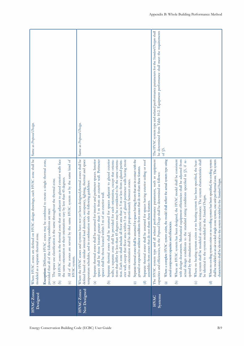
Appendix B: Whole Building Performance Method
Energy Conservation Building Code (ECBC) User Guide B.9
HV
AC
Zon
es
Des
igne
dW
here
HVA
C z
ones
are
defi
ned
on H
VAC
des
ign
draw
ings
, eac
h H
VAC
zon
e sh
all b
e m
odel
ed a
s a
sepa
rate
ther
mal
zon
e.
Exc
epti
on: D
iffer
ent
HVA
C z
ones
may
be
com
bine
d to
cre
ate
a si
ngle
the
rmal
zon
e,
prov
ided
that
all
of th
e fo
llow
ing
cond
ition
s ar
e m
et:
The
spa
ce u
se c
lass
ifica
tion
is th
e sa
me
thro
ugho
ut th
e th
erm
al z
one.
(a)
All
HVA
C z
ones
in th
e th
erm
al z
one
that
are
adj
acen
t to
glaz
ed e
xter
ior w
alls
face
(b
) th
e sa
me
orie
ntat
ion
or th
eir o
rient
atio
ns v
ary
by le
ss th
an 4
5 de
gree
s.
All
of t
he z
ones
are
ser
ved
by t
he s
ame
HVA
C s
yste
m o
r by
the
sam
e ki
nd o
f (c
) H
VAC
sys
tem
.
Sam
e as
Pro
posed
Desi
gn.
HV
AC
Zon
es
Not
Des
igne
dW
here
the
HVA
C z
ones
and
sys
tem
s ha
ve n
ot y
et b
een
desi
gned
,ther
mal
zon
es s
hall
be
defin
ed b
ased
on
sim
ilar
inte
rnal
load
den
sitie
s, oc
cupa
ncy,
light
ing,
ther
mal
and
spa
ce
tem
pera
ture
sch
edul
es, a
nd in
com
bina
tion
with
the
follo
win
g gu
idel
ines
:
Sepa
rate
ther
mal
zon
es s
hall
be a
ssum
ed fo
r int
erio
r and
per
imet
er s
pace
s. In
terio
r (a
) sp
aces
sha
ll be
tho
se l
ocat
ed g
reat
er t
han
5 m
fro
m a
n ex
terio
r w
all.
Perim
eter
sp
aces
sha
ll be
thos
e lo
cate
d w
ithin
5 m
of
an e
xter
ior w
all.
Sepa
rate
the
rmal
zon
es s
hall
be a
ssum
ed f
or s
pace
s ad
jace
nt t
o gl
azed
ext
erio
r (b
) w
alls
; a s
epar
ate
zone
sha
ll be
pro
vide
d fo
r ea
ch o
rient
atio
n, e
xcep
t th
at o
rient
a-tio
ns th
at d
iffer
by
less
than
45
degr
ees
may
be
cons
ider
ed to
be
the
sam
e or
ient
a-tio
n. E
ach
zone
sha
ll in
clud
e al
l floo
r ar
ea th
at is
5 m
or
less
from
a g
laze
d pe
rim-
eter
wal
l, ex
cept
that
floo
r ar
ea w
ithin
5 m
of
glaz
ed p
erim
eter
wal
ls h
avin
g m
ore
than
one
orie
ntat
ion
shal
l be
divi
ded
prop
ortio
nate
ly b
etw
een
zone
s.
Sepa
rate
ther
mal
zone
s sha
ll be a
ssum
ed fo
r spa
ces h
avin
g flo
ors t
hat a
re in
cont
act w
ith th
e (c
) gr
ound
or e
xpos
ed to
ambi
ent c
ondi
tions
from
zon
es th
at d
o no
t sha
re th
ese f
eatu
res.
Sepa
rate
the
rmal
zon
es s
hall
be a
ssum
ed f
or s
pace
s ha
ving
ext
erio
r ce
iling
or
roof
(d
) as
sem
blie
s fr
om z
ones
that
do
not s
hare
thes
e fe
atur
es.
Sam
e as
Pro
posed
Desi
gn.
HV
AC
Sy
stem
sT
he H
VAC
sys
tem
typ
e an
d al
l re
late
d pe
rfor
man
ce p
aram
eter
s, su
ch a
s eq
uipm
ent
capa
citie
s an
d ef
ficie
ncie
s, in
the
Prop
osed
Desi
gn s
hall
be d
eter
min
ed a
s fo
llow
s:
Whe
re a
com
plet
e H
VAC
syste
m e
xists,
the
mod
el sh
all re
flect
the
actu
al sy
stem
type
usin
g (a
) ac
tual
com
pone
nt ca
pacit
ies an
d ef
ficien
cies.
Whe
re a
n H
VAC
sys
tem
has
bee
n de
sign
ed, t
he H
VAC
mod
el s
hall
be c
onsi
sten
t (b
) w
ith d
esig
n do
cum
ents
. Mec
hani
cal e
quip
men
t effi
cien
cies
sha
ll be
adj
uste
d fr
om
actu
al d
esig
n co
nditi
ons
to t
he s
tand
ard
ratin
g co
nditi
ons
spec
ified
in
§5,
if r
e-qu
ired
by th
e si
mul
atio
n m
odel
.
Whe
re n
o he
atin
g sy
stem
exi
sts
or n
o he
atin
g sy
stem
has
bee
n sp
ecifi
ed, t
he h
eat-
(c)
ing
syst
em s
hall
be m
odel
ed a
s el
ectr
ic r
esis
tanc
e. T
he s
yste
m c
hara
cter
istic
s sh
all
be id
entic
al to
the
syst
em m
odel
ed in
the
Stan
dard
Desi
gns.
Whe
re n
o co
olin
g sy
stem
exist
s or n
o co
olin
g sy
stem
has
bee
n sp
ecifi
ed, t
he co
olin
g sy
stem
(d
) sh
all b
e mod
eled
as an
air-c
ooled
sing
le-zo
ne sy
stem
, one
uni
t per
ther
mal
zone
. The
syste
m
char
acte
ristic
s sha
ll be i
dent
ical t
o th
e sys
tem
mod
eled
in th
e Stan
dard
Desi
gns.
The
HVA
C sy
stem
type
and
rela
ted
perf
orm
ance
par
amet
ers f
or th
e St
anda
rd D
esign
s sha
ll be
det
erm
ined
fro
m T
able
10.
2. E
quip
men
t pe
rfor
man
ce s
hall
mee
t th
e re
quire
men
ts
of §
5.
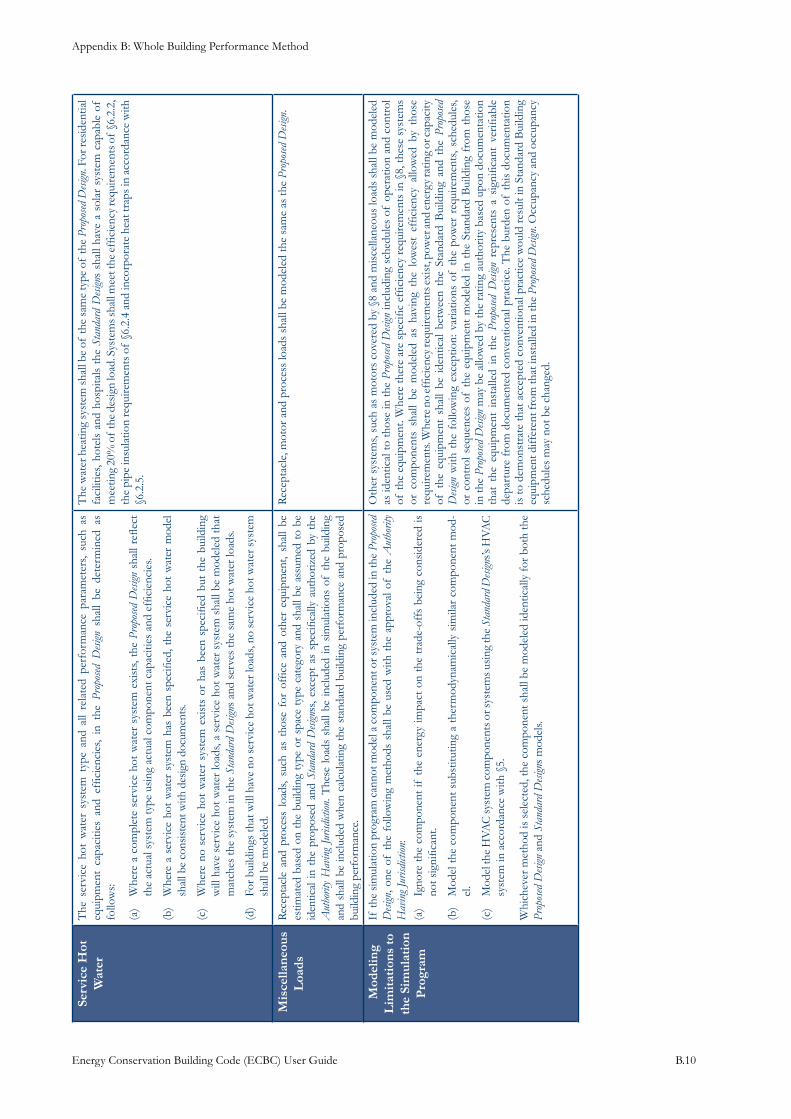
Appendix B: Whole Building Performance Method
Energy Conservation Building Code (ECBC) User Guide B.10
Serv
ice
Hot
W
ater
The
ser
vice
hot
wat
er s
yste
m t
ype
and
all
rela
ted
perf
orm
ance
par
amet
ers,
such
as
equi
pmen
t ca
paci
ties
and
effic
ienc
ies,
in t
he P
ropo
sed D
esign
sha
ll be
det
erm
ined
as
follo
ws: Whe
re a
com
plet
e se
rvic
e ho
t w
ater
sys
tem
exi
sts,
the
(a)
Prop
osed
Desi
gn s
hall
refle
ct
the
actu
al s
yste
m ty
pe u
sing
act
ual c
ompo
nent
cap
aciti
es a
nd e
ffici
enci
es.
Whe
re a
ser
vice
hot
wat
er s
yste
m h
as b
een
spec
ified
, the
ser
vice
hot
wat
er m
odel
(b
) sh
all b
e co
nsist
ent w
ith d
esig
n do
cum
ents
.
Whe
re n
o se
rvic
e ho
t w
ater
sys
tem
exi
sts
or h
as b
een
spec
ified
but
the
bui
ldin
g (c
) w
ill h
ave
serv
ice
hot w
ater
load
s, a
serv
ice
hot w
ater
sys
tem
sha
ll be
mod
eled
that
m
atch
es th
e sy
stem
in th
e St
anda
rd D
esign
s an
d se
rves
the
sam
e ho
t wat
er lo
ads.
For b
uild
ings
that
will
hav
e no
ser
vice
hot
wat
er lo
ads,
no s
ervi
ce h
ot w
ater
sys
tem
(d
) sh
all b
e m
odel
ed.
The
wat
er h
eatin
g sy
stem
shal
l be
of th
e sa
me
type
of
the
Prop
osed
Desi
gn. F
or re
side
ntia
l fa
cilit
ies,
hote
ls a
nd h
ospi
tals
the
Sta
ndar
d D
esign
s sh
all h
ave
a so
lar
syst
em c
apab
le o
f m
eetin
g 20
% o
f th
e de
sign
load
. Sys
tem
s sha
ll m
eet t
he e
ffici
ency
requ
irem
ents
of
§6.2
.2,
the
pipe
insu
latio
n re
quire
men
ts o
f §6
.2.4
and
inco
rpor
ate
heat
trap
s in
acco
rdan
ce w
ith
§6.2
.5.
Mis
cella
neou
s L
oads
Rec
epta
cle
and
proc
ess
load
s, su
ch a
s th
ose
for
offic
e an
d ot
her
equi
pmen
t, sh
all
be
estim
ated
bas
ed o
n th
e bu
ildin
g ty
pe o
r sp
ace
type
cat
egor
y an
d sh
all b
e as
sum
ed t
o be
id
entic
al in
the
pro
pose
d an
d St
anda
rd D
esign
ss, e
xcep
t as
spe
cific
ally
aut
horiz
ed b
y th
e A
utho
rity
Hav
ing
Juris
dicti
on. T
hese
load
s sh
all b
e in
clud
ed in
sim
ulat
ions
of
the
build
ing
and
shal
l be
incl
uded
whe
n ca
lcul
atin
g th
e st
anda
rd b
uild
ing
perf
orm
ance
and
pro
pose
d bu
ildin
g pe
rfor
man
ce.
Rec
epta
cle,
mot
or a
nd p
roce
ss lo
ads
shal
l be
mod
eled
the
sam
e as
the
Prop
osed
Desi
gn.
Mod
elin
g L
imit
atio
ns to
th
e Si
mul
atio
n P
rogr
am
If th
e si
mul
atio
n pr
ogra
m c
anno
t mod
el a
com
pone
nt o
r sys
tem
incl
uded
in th
e Pr
opos
ed
Desi
gn, o
ne o
f th
e fo
llow
ing
met
hods
sha
ll be
use
d w
ith t
he a
ppro
val o
f th
e A
utho
rity
Hav
ing J
urisd
iction
:Ig
nore
the
com
pone
nt if
the
ene
rgy
impa
ct o
n th
e tr
ade-
offs
bei
ng c
onsi
dere
d is
(a
) no
t sig
nific
ant.
Mod
el th
e co
mpo
nent
sub
stitu
ting
a th
erm
odyn
amic
ally
sim
ilar
com
pone
nt m
od-
(b)
el.
Mod
el th
e H
VAC
syst
em c
ompo
nent
s or s
yste
ms u
sing
the
(c)
Stan
dard
Desi
gns’s
HVA
C
syst
em in
acc
orda
nce
with
§5.
Whi
chev
er m
etho
d is
sel
ecte
d, th
e co
mpo
nent
sha
ll be
mod
eled
iden
tical
ly fo
r bot
h th
e Pr
opos
ed D
esign
and
Sta
ndar
d D
esign
s m
odel
s.
Oth
er s
yste
ms,
such
as
mot
ors
cove
red
by §
8 an
d m
isce
llane
ous
load
s sh
all b
e m
odel
ed
as id
entic
al to
thos
e in
the
Prop
osed
Desi
gn in
clud
ing
sche
dule
s of
ope
ratio
n an
d co
ntro
l of
the
equi
pmen
t. W
here
ther
e ar
e sp
ecifi
c ef
ficie
ncy
requ
irem
ents
in §
8, th
ese
syst
ems
or c
ompo
nent
s sh
all
be m
odel
ed a
s ha
ving
the
low
est
effic
ienc
y al
low
ed b
y th
ose
requ
irem
ents
. Whe
re n
o ef
ficie
ncy r
equi
rem
ents
exis
t, po
wer
and
ener
gy ra
ting
or ca
paci
ty
of t
he e
quip
men
t sh
all
be i
dent
ical
bet
wee
n th
e St
anda
rd B
uild
ing
and
the
Prop
osed
D
esign
with
the
fol
low
ing
exce
ptio
n: v
aria
tions
of
the
pow
er r
equi
rem
ents
, sch
edul
es,
or c
ontr
ol s
eque
nces
of
the
equi
pmen
t m
odel
ed in
the
Sta
ndar
d B
uild
ing
from
tho
se
in th
e Pr
opos
ed D
esign
may
be
allo
wed
by
the
ratin
g au
thor
ity b
ased
upo
n do
cum
enta
tion
that
the
equ
ipm
ent
inst
alle
d in
the
Pro
posed
Desi
gn r
epre
sent
s a
sign
ifica
nt v
erifi
able
de
part
ure
from
doc
umen
ted
conv
entio
nal p
ract
ice.
The
bur
den
of th
is d
ocum
enta
tion
is to
dem
onst
rate
that
acc
epte
d co
nven
tiona
l pra
ctic
e w
ould
resu
lt in
Sta
ndar
d B
uild
ing
equi
pmen
t diff
eren
t fro
m th
at in
stal
led
in th
e Pr
opos
ed D
esign
. Occ
upan
cy a
nd o
ccup
ancy
sc
hedu
les
may
not
be
chan
ged.
Appendix B: Whole Building Performance Method
Energy Conservation Building Code (ECBC) User Guide B.11
Calculating Proposed and Standard Design10.3.1.1
Design Modela)
The Proposed Design and the corresponding Standard Design shall be consistent with information contained on the plans and specifications. Some buildings, such as retail malls and speculative office buildings typically are built in phases. For example, the core mechanical system may be installed with the base building, while the ductwork and terminal units are installed later as part of tenant improvements.
For the purpose of calculating the Proposed Building, the rule is simple: the features that are not yet designed or documented in the construction documents are assumed to minimally comply with the applicable prescriptive requirements of the ECBC, as specified in Sections 4 through 8. In cases where the space use classification is not known, the default assumption is to classify it as office space using the Building Area Method.
The WBP method is based on the assumption that non-residential buildings are both heated and cooled. Even if not installed initially, it is common for buildings lacking a heating or cooling system to have one retrofitted by future occupants. Accordingly, there is a special rule for calculating energy use in the Proposed Design when a building’s HVAC system is heating-only or cooling-only: the building must be modeled as if it is going to have both heating and cooling. The missing system is modeled as the default heating or cooling system that just meets the prescriptive requirements of the ECBC. The same system is modeled for both Standard and Proposed Designs. (Refer ECBC §4.0).
Space Use Classificationsb)
A key task in modeling the Proposed Design is assigning space use classifications to different areas of the building. These classifications are used to assign lighting power density assumptions and to differentiate areas within the building that may have different operating schedules and characteristics (thermostat settings, ventilation rates, etc.). The choice of space use classifications is taken from one of the two lighting tables in the ECBC: either Table 7.1 (Interior Lighting Power-Building area method) or Table 7.2 (Interior Lighting Power- Space Function method). The designer may choose either classification scheme but may not mix the schemes by using one for part of the building and the other for the rest of the building. “Building,” in this context, refers to the space encompassed by a single building permit application, which may be less than the complete building.
The secondary support areas associated with each of the major building types would be included in each building type. For example, if a building included both office and retail areas, the corridors and restrooms associated with the office occupancy would be included in the office area and the storage or/and dressing room areas associated with the sales floor would be included in the retail area.
Schedulesc)
Schedules are used to describe the percentage of a maximum design value of an internal load that is applicable during a particular time period, usually one hour, i.e., lighting power density, miscellaneous equipment (plug load) power density, occupant load or any other significant load thermostat set point (s) applicable in this time period, or the availability (on/off), and control operation of a system or system component, e.g., cooling systems, fans, chillers, or pumps.
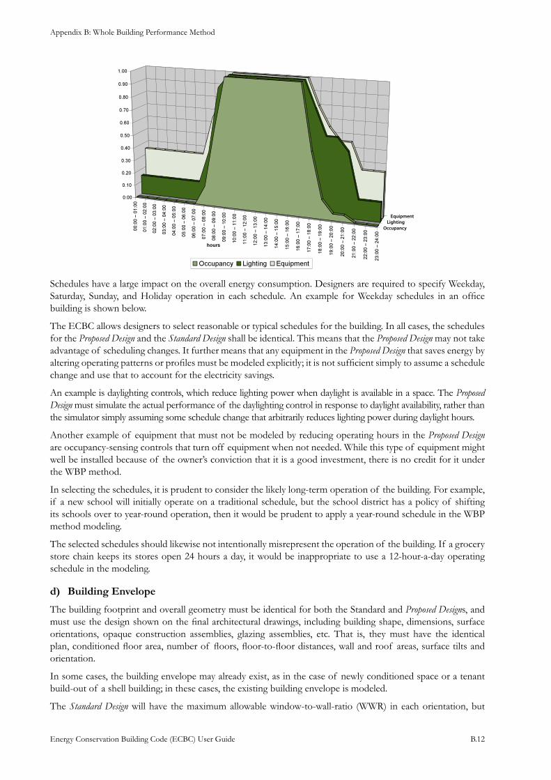
Appendix B: Whole Building Performance Method
Energy Conservation Building Code (ECBC) User Guide B.12
OccupancyLighting
Equipment
Schedules have a large impact on the overall energy consumption. Designers are required to specify Weekday, Saturday, Sunday, and Holiday operation in each schedule. An example for Weekday schedules in an office building is shown below.
The ECBC allows designers to select reasonable or typical schedules for the building. In all cases, the schedules for the Proposed Design and the Standard Design shall be identical. This means that the Proposed Design may not take advantage of scheduling changes. It further means that any equipment in the Proposed Design that saves energy by altering operating patterns or profiles must be modeled explicitly; it is not sufficient simply to assume a schedule change and use that to account for the electricity savings.
An example is daylighting controls, which reduce lighting power when daylight is available in a space. The Proposed Design must simulate the actual performance of the daylighting control in response to daylight availability, rather than the simulator simply assuming some schedule change that arbitrarily reduces lighting power during daylight hours.
Another example of equipment that must not be modeled by reducing operating hours in the Proposed Design are occupancy-sensing controls that turn off equipment when not needed. While this type of equipment might well be installed because of the owner’s conviction that it is a good investment, there is no credit for it under the WBP method.
In selecting the schedules, it is prudent to consider the likely long-term operation of the building. For example, if a new school will initially operate on a traditional schedule, but the school district has a policy of shifting its schools over to year-round operation, then it would be prudent to apply a year-round schedule in the WBP method modeling.
The selected schedules should likewise not intentionally misrepresent the operation of the building. If a grocery store chain keeps its stores open 24 hours a day, it would be inappropriate to use a 12-hour-a-day operating schedule in the modeling.
Building Enveloped)
The building footprint and overall geometry must be identical for both the Standard and Proposed Designs, and must use the design shown on the final architectural drawings, including building shape, dimensions, surface orientations, opaque construction assemblies, glazing assemblies, etc. That is, they must have the identical plan, conditioned floor area, number of floors, floor-to-floor distances, wall and roof areas, surface tilts and orientation.
In some cases, the building envelope may already exist, as in the case of newly conditioned space or a tenant build-out of a shell building; in these cases, the existing building envelope is modeled.
The Standard Design will have the maximum allowable window-to-wall-ratio (WWR) in each orientation, but
Appendix B: Whole Building Performance Method
Energy Conservation Building Code (ECBC) User Guide B.13
the Proposed Design may exceed this limit, provided compliance is achieved. Opaque assemblies like walls, roofs and floors must be described by material layer as per the architectural drawings. For the Standard Design, the characteristics (U-factor) of these envelope components are set to the prescriptive values specified in ECBC §4.0.
The heat capacities for each assembly type must match the heat capacities of the Proposed Design. This is because heat capacities may have a significant effect on the performance of envelope components, which shows up in the simulation runs but they are not a requirement of the ECBC. Heat capacity is modeled to be the same in both the Proposed Design and the Standard Design simulation runs, and so is energy neutral under the WBP method.
For the Standard Design, exterior roof surfaces, other than those with ventilated attics, must be modeled assuming a surface reflectance value of 0.30 (Refer ECBC Table 10.1). If a Proposed Design calls for a reflective roof surface, however, the model may assume a long-term average reflectance of 0.45, which results in the lower heat absorption of the reflective surface and makes a conservative allowance for degradation of the reflectivity over its lifetime. For this exception to be allowed the specified reflectance of the roof in the Proposed Design must exceed 0.70 and its emittance must exceed 0.75. (As per ASHRAE 90.1, 2004)
Windows /Fenestrationi) The solar, thermal, and optical performance of windows systems are defined by the combination of four main parameters, i.e., the area as defined by the window-to-wall ratio, thermal transmittance (U-factor), Solar Heat Gain Coefficient (SHGC), and Visible Light Transmission (VLT).
Fenestration Area• Fenestration areas and performance are strong drivers of energy use in buildings. Therefore, the ECBC places great emphasis in how these values are calculated and applied for compliance.
ECBC §4.3.3 sets the prescriptive upper limits on vertical fenestration area and skylight area. If the fenestration areas for the Proposed Design are less than these limits, the Standard Design shall have the same areas and orientations as the Proposed Design.
If the fenestration areas in the Proposed Design exceed these limits, then the corresponding areas in the Standard Design must be adjusted down to these limits AND corresponding increases made to opaque areas so that the gross wall area and gross roof area are the same for both the Proposed Design and the Standard Design.
ECBC’s prescriptive envelope requirements do not provide an exception for street-level, street-side vertical fenestration (e.g., store display windows). Thus, such fenestration must be modeled identically for the Proposed Design and the Standard Design simulation runs so that the representation of these types of fenestration is energy neutral.
U-Factors• The U-factor for the Standard Design is set to the minimum required for the climate, as specified in ECBC Table 4.3. The minimum U-factor is a function of the percentage of glazing (WWR) in a wall or roof, as described above.
Solar Heat Gain Coefficient• The solar heat gain coefficient value for the fenestration applied in the Standard Design is set to the maximum required for the climate and for each orientation, as specified in ECBC Table 4.3. The maximum SHGC is a function of the glazing percentage of wall or roof, which is based on the Proposed Design as described above.
If the vertical fenestration to be used is unrated, then the SHGC values in ECBC Table 11.1 must be used.
Shading of Fenestrationii) Glazing installed in the Standard Design must be modeled as being flush with its wall or roof surface, and without any external shading devices. This ruling allows the Proposed Design to use to its advantage shading from window recesses, overhangs, side fins, or other permanent shading devices that reduce solar gains on the glazing.
Appendix B: Whole Building Performance Method
Energy Conservation Building Code (ECBC) User Guide B.14
Interior shading devices, if not automatic, should not be modeled in the Proposed Design. In Standard Design, no shading should be modeled.
Exceptions for Envelope
Any simulation program necessarily relies on a somewhat simplified description of the building envelope. It is usually time-consuming and difficult to explicitly detail every minor variation in the envelope design, and if good engineering judgment is applied, these simplifications won’t result in a significant decline in accuracy. Three exceptions, where more substantial simplifications may be made, are:
Minor Assemblies: Frequently, there will be small areas on the building envelope with unique thermal characteristics. The ECBC exempts any envelope assembly that covers less than 5% of the total area of a given assembly type (e.g., exterior walls or roofs) from being treated as a separate envelope component. Instead, that area may be added to an adjacent assembly of the same type. For example, if there is an exterior wall constructed of load-bearing masonry, but there are small wood-framed infill areas, the infill areas may be treated as if the entire wall is of masonry. Note that the gross wall area is unchanged, and no areas are left out of the model.
Different Tilt or Azimuth: This exception, primarily intended to address curved surfaces, specifies the minimum number of orientations into which these surfaces must be split up. The Standard allows similarly oriented surfaces to be grouped under a single tilt or azimuth, provided they are of similar construction and provided the tilt or azimuth of the surfaces are within 45 degree of each other. They may be grouped as a single surface or a multiplier may be used.
Fenestration: Interior and/or exterior shading devices in the Proposed Design shall not be modeled unless they are automatically controlled. In the Standard Design, shades of any kind are not modeled. When the window area in the Proposed Design exceeds the prescriptive maximum, the window area in the Standard Design is set to the prescriptive maximum area and representative opaque wall area replaces any excess window area. Thus the overall wall area (opaque wall + window area) is the same for both standard and proposed buildings. The window area in Standard Design is decreased uniformly in each orientation so that the fraction of total window area in each direction is the same in both Standard Design and Proposed Design simulation models.
Lighting Systemse)
Under the WBP method, lighting systems are a very important part of overall building performance for most non-residential building types. Any lighting system efficiency improvements or reductions are reflected as energy savings in the WBP method. The description of lighting systems in building energy simulation models must incorporate the following two characteristics:
Application of a lighting power density (LPD) for each space or thermal zone of the building model. • This may be determined using one of the two methods defined in §7.3.2 (building area method) or §7.3.3 (space function method).
An operational schedule for the lighting system which describes the percentage of the maximum LPD • value that is energized during a particular hour
There are further requirements if the electric lighting system is to be controlled in response to the amount of daylight in perimeter zones of the building. In such cases, the building simulation program must be able to explicitly model daylight levels in each perimeter space that has daylight linking. Light sensors must be modeled in these zones, and a control strategy must be applied that modulates electrical energy output from the electric lighting system. Typically there are at least three daylight linked control schemes to modulate electrical energy output:
Stepped control: in this control scheme, the electrical lighting system can respond to the presence of • daylight in defined steps
Linear control: the lighting system modulates it’s output in a linear function to a prescribed minimum • level, and
Appendix B: Whole Building Performance Method
Energy Conservation Building Code (ECBC) User Guide B.15
Linear/off: the lighting system modulates it’s output in a linear function and will switch off (use zero • electrical energy) when there is sufficient daylight in the space
Either the building area or space function method may be used, but the categorization of spaces must be identical between the Standard Design and the Proposed Design.
The LPD for the Proposed Design is taken from the design documents for the building. If a lighting system already exists, then the lighting system design for Proposed Design will be based on the actual lighting power density of the existing system. In the special case where no lighting system or design exists, as in a shell building where the lighting will be installed by a future tenant, then a default lighting power density must be assumed, based on the building area method for the appropriate building type. If no building type is known, then an office building is assumed, (refer ECBC Table 10.1)
Exterior lighting systems as defined in ECBC §7.2.3 refers to grounds luminaires which operate at greater than 100W. They shall contain lamps having a minimum efficacy of 60 lm/W unless, the luminaire is controlled by a motion sensor or exempt under §7.1, as mentioned below:
Emergency lighting that is automatically off during normal building operation and is powered by • battery, generator, or other alternate power source
Lighting in dwelling units •
HVAC f)
Incorporating HVAC systems into whole building energy simulation models is a complex process. It requires knowledge of how buildings respond to climate, in addition to knowledge of the configuration of HVAC systems and appropriate control strategies. For the purpose of building energy simulation it is useful to think of the building model as having three HVAC type components, ZONES, SYSTEMS and PLANT.
HVAC Zoning i) A key task in developing both of the simulation models is to divide the Proposed Design into a series of spaces or “thermal zones” to be input to the energy simulation program. Due care and consideration needs to be taken to divide the building into an appropriate number of thermal zones. There are several considerations for this division, and some of these considerations can be conflicting. The following are some of the considerations that need to be thought through when dividing the building for simulation analysis.
Building areas that are thermodynamically similar spaces and whose heating and cooling loads can be satisfied through use of a single thermostat (or other type of temperature control) can be combined in a single thermal zone. Since this requires mapping of the HVAC system design into the simulation model, the simulator needs to work interactively with the services consultant.
Building areas that perform a similar function in the building design may be combined to form a thermal zone – for example, some open plan office areas, or retail shop areas that have similar loads and operate similar hours may be combined. These areas would have identical schedules applied for operation of internal loads and HVAC systems.
Building areas that have the same lighting power density may be combined, i.e. the use of “space use classifications.” The choice of space use classifications is taken from one of the two lighting tables in the ECBC, either Table 7.1 (Interior Lighting Power-Building area method) or Table 7.2 (Interior Lighting Power-Space Function method). The designer may choose either classification scheme but may not mix the schemes by using one for part of the building and the other for the rest of the building.
“Building” in this context refers to the space encompassed by a single building permit application, which may be less than the complete building. The secondary support areas associated with each of the major building types would be included in each building type. For example, if a building included both office and retail areas, the corridors and restrooms associated with the office occupancy would be included in the office area and the storage or/and dressing room areas associated with the sales floor would be included in the retail area.
HVAC Zones are identical to the thermal zones or spaces discussed earlier. An HVAC designer will consider the
Appendix B: Whole Building Performance Method
Energy Conservation Building Code (ECBC) User Guide B.16
internal and external loads on each zone to calculate a “design day” cooling and heating load, and the maximum outside air ventilation required. He or she may combine two or more thermal zones into a “thermal block” designed to be conditioned by a single HVAC SYSTEM, for example, an Air Handling Unit (AHU) or an DX system. If the building uses central air-conditioning systems (as opposed to DX systems, see Chapter 5), then a series of HVAC SYSTEMS may be served by one or more HVAC PLANT component (chillers, pumps, cooling towers etc).
For the WBP method using building energy simulation analysis, HVAC ZONES must be described to be identical in both the Standard Design and the Proposed Design Models. This rule ensures consistency with the requirement that the shape and area of the building envelope for the Standard Design be the same as for the Proposed Design, and that the space use classifications be the same.
HVAC Zoning Based On HVAC Design
As noted earlier, building areas that are thermodynamically similar spaces and whose heating and cooling loads can be satisfied through use of a single thermostat (or other type of temperature control) can be combined in a single thermal zone. The outside air flow quantities, and control strategies applicable to the duct outlets or other terminal units controlled by this single thermostats may be part of the HVAC ZONE description. Clearly, this process requires mapping of the HVAC SYSTEM design into the simulation model, and the simulator needs to work interactively with the services consultant.
Use of HVAC Zone Multiplier
In some simulation programs, the interior HVAC ZONES of a multi-story building, which may be physically separate zones on each floor can be reasonably combined and treated as a single thermal zone with a multiplier. Use of a multiplier allows simplification of the calculation of electricity consumption for the whole building without having to repeatedly describe many similar or identical zones in the simulation model, thus saving time and effort without significant loss of accuracy. However, a cafeteria or computer room in an office building would need to be modeled separately, as would lower-floor retail uses.
The following conditions must be met to be able to use the multiplier option:
All of the space use classifications must be the same throughout the thermal zone. This ensures that • they have the same load and schedule characteristics.
For exterior (or perimeter) HVAC ZONES with glazing, the glazing for all zones included in the • thermal block must have the same orientation or at least their orientations must be within 45 degrees of each other. This ensures that they have the same solar heat gain characteristics. This is not to say that the zones may not have two or more glazing orientations – a corner office could easily have two – but that the zones must have similar orientations. It would be acceptable, for example, to group all of the northeast corner offices on the intermediate floors of an office tower into a single thermal block.
All of the HVAC ZONES in different floors must be served either by the same HVAC SYSTEM or • by the same kind of HVAC SYSTEM. This is so that the simulation program can accurately model the performance of the system (s) serving the zones.
HVAC Zoning When No HVAC Design Exists
In a situation where an HVAC ZONING plan has not been designed, then a configuration of thermal blocks must be assumed for the WBP method. This situation is quite common in commercial buildings where the future tenants will determine the zoning of spaces in the building. In this case, the building must be divided into thermal zones based on similar internal load densities and lighting power densities, operational schedules, occupancy patterns, space temperature schedules, etc. There are several guidelines that should be followed in this situation, as described below.
Zoning Based on Perimeter and Interior Spaces
In situations when no HVAC design has been developed, divide the floor plate into perimeter spaces than are within 5 meters of an exterior wall, and interior spaces that are more than 5 meters from an exterior wall.
Appendix B: Whole Building Performance Method
Energy Conservation Building Code (ECBC) User Guide B.17
Zoning Based on Glazing Orientation
Glazed exterior walls should be assigned to different perimeter thermal zones for each major orientation. Orientations within 45 degrees of each other may be combined. Spaces with two or more glazed orientations, such as corner offices, should be divided proportionately between zones having the different orientations.
Zoning Based on Floor Levels
Spaces exposed to ambient conditions, such as the top floor or an overhanging floor, and spaces in contact with the ground, such as the ground floor, must be zoned separately from zones that are not exposed to ambient conditions, such as intermediate floors in a multi-story building. Therefore, a multi-storey tower office building could be divided into a top floor, a typical middle floor with the appropriate floor multiplier, and a bottom floor.
Thermal Zones For Multi-Family Residential Buildings
Multifamily residential buildings are another special case. In general, the residential spaces must be treated as separate thermal zones, except that some combinations are allowed. Units all facing the same orientation, and having similar conditions at the top, bottom, and sides, may be combined. Similar corner units may be combined, and units with similar roof or floor loads may be combined.
HVAC Systemsii) Defining HVAC systems for use with whole building simulation programs is complex, and there are many inter-related rules. Some of the rules that govern the description of HVAC SYSTEMS for the ECBC whole building performance method are:
The HVAC SYSTEM described in the • Standard Design Model should just meet the prescriptive requirements of the ECBC. These requirements are deemed representative of current standard practice that meets the ECBC.
Where possible, the HVAC SYSTEM is to be conceptualized as completely as possible on the actual system • designed for the Proposed Design. This includes the system type, equipment capacities and efficiencies, controls, ancillary features (such as economizers), etc. The equipment efficiencies may need to be adjusted to meet the needs of the simulation program. While efficiencies may be most accurately specified at the building’s design conditions, most simulation programs require efficiencies to be specified at standard rating conditions, such as those given in ECBC §5.0.
Where the entire HVAC SYSTEM design is not known, as in the case of a shell-and-core design, the • unknown parts of the system are assumed to just meet the prescriptive requirements of the ECBC and to be energy neutral. This strategy prevents gamesmanship with the undefined system components. Gamesmanship is the practice of artificially reducing the efficiency of the Standard Design in order to increase the apparent relative efficiency of the Proposed Design4.
Where the complete HVAC SYSTEM exists, the • Proposed Design and Standard Design are based on the existing HVAC system – for example, fit out of an existing speculative building for a tenant. The subject of the building permit is primarily the interior construction and lighting system and does not include the HVAC system because it has already been built and permitted. Both simulation models would also include the existing building envelope.
Where no HEATING SYSTEM exists, a default heating system must be assumed and modeled. It should • be a simple heating system that burns fossil fuel, sized with sufficient capacity to meet the design heating loads for the Proposed Design. An identical system (with sizing adjustments) must be assumed for the Standard Design.
4 The WBP method is more vulnerable to this sort of abuse, which is why the rules for constructing the Standard Design must be so specific. The WBP modeling rules for part-load efficiency and system sizing are intended to minimize these effects on the trade-off calculations for the other measures in the building. For example, electricity consumption differences cannot be gained for a difference between a properly sized HVAC system in the Proposed Design and an improperly sized HVAC system for the Standard Design. The modeling rules are discussed individually in the following sections:
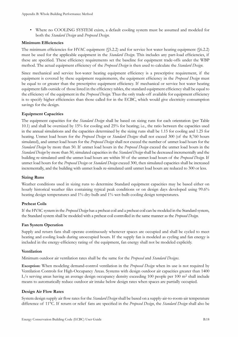
Appendix B: Whole Building Performance Method
Energy Conservation Building Code (ECBC) User Guide B.18
Where no COOLING SYSTEM exists, a default cooling system must be assumed and modeled for • both the Standard Design and Proposed Design.
Minimum Efficiencies
The minimum efficiencies for HVAC equipment (§5.2.2) and for service hot water heating equipment (§6.2.2) must be used for the applicable equipment in the Standard Design. This includes any part-load efficiencies, if these are specified. These efficiency requirements set the baseline for equipment trade-offs under the WBP method. The actual equipment efficiency of the Proposed Design is then used to calculate the Standard Design.
Since mechanical and service hot-water heating equipment efficiency is a prescriptive requirement, if the equipment is covered by these equipment requirements, the equipment efficiency in the Proposed Design must be equal to or greater than the prescriptive equipment efficiency. If mechanical or service hot water heating equipment falls outside of those listed in the efficiency tables, the standard equipment efficiency shall be equal to the efficiency of the equipment in the Proposed Design. Thus the only trade-off available for equipment efficiency is to specify higher efficiencies than those called for in the ECBC, which would give electricity consumption savings for the design.
Equipment Capacities
The equipment capacities for the Standard Design shall be based on sizing runs for each orientation (per Table 10.1) and shall be oversized by 15% for cooling and 25% for heating; i.e., the ratio between the capacities used in the annual simulations and the capacities determined by the sizing runs shall be 1.15 for cooling and 1.25 for heating. Unmet load hours for the Proposed Design or Standard Designs shall not exceed 300 (of the 8,760 hours simulated), and unmet load hours for the Proposed Design shall not exceed the number of unmet load hours for the Standard Design by more than 50. If unmet load hours in the Proposed Design exceed the unmet load hours in the Standard Design by more than 50, simulated capacities in the Standard Design shall be decreased incrementally and the building re-simulated until the unmet load hours are within 50 of the unmet load hours of the Proposed Design. If unmet load hours for the Proposed Design or Standard Design exceed 300, then simulated capacities shall be increased incrementally, and the building with unmet loads re-simulated until unmet load hours are reduced to 300 or less.
Sizing Runs
Weather conditions used in sizing runs to determine Standard equipment capacities may be based either on hourly historical weather files containing typical peak conditions or on design days developed using 99.6% heating design temperatures and 1% dry-bulb and 1% wet-bulb cooling design temperatures.
Preheat Coils
If the HVAC system in the Proposed Design has a preheat coil and a preheat coil can be modeled in the Standard system, the Standard system shall be modeled with a preheat coil controlled in the same manner as the Proposed Design.
Fan System Operation
Supply and return fans shall operate continuously whenever spaces are occupied and shall be cycled to meet heating and cooling loads during unoccupied hours. If the supply fan is modeled as cycling and fan energy is included in the energy-efficiency rating of the equipment, fan energy shall not be modeled explicitly.
Ventilation
Minimum outdoor air ventilation rates shall be the same for the Proposed and Standard Designs.
Exception: When modeling demand-control ventilation in the Proposed Design when its use is not required by Ventilation Controls for High-Occupancy Areas. Systems with design outdoor air capacities greater than 1400 L/s serving areas having an average design occupancy density exceeding 100 people per 100 m2 shall include means to automatically reduce outdoor air intake below design rates when spaces are partially occupied.
Design Air Flow Rates
System design supply air flow rates for the Standard Design shall be based on a supply-air-to-room-air temperature difference of 11°C. If return or relief fans are specified in the Proposed Design, the Standard Design shall also be
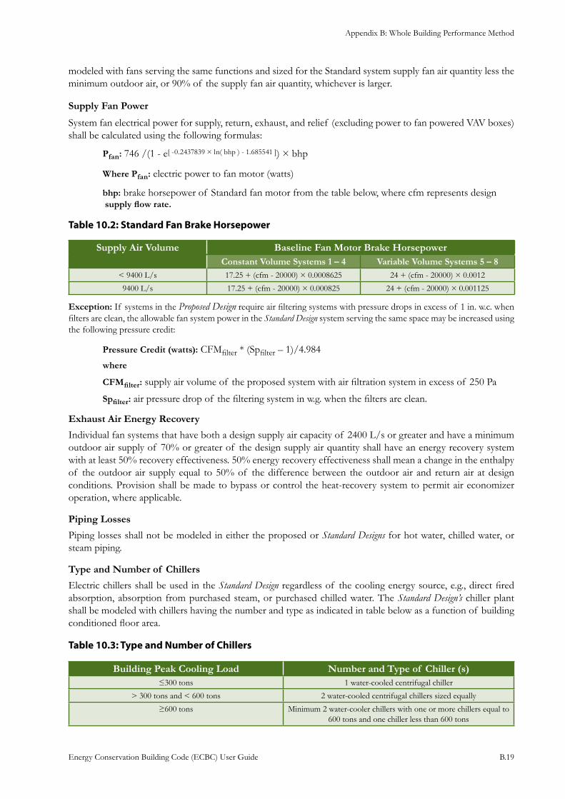
Appendix B: Whole Building Performance Method
Energy Conservation Building Code (ECBC) User Guide B.19
modeled with fans serving the same functions and sized for the Standard system supply fan air quantity less the minimum outdoor air, or 90% of the supply fan air quantity, whichever is larger.
Supply Fan Power
System fan electrical power for supply, return, exhaust, and relief (excluding power to fan powered VAV boxes) shall be calculated using the following formulas:
Pfan: 746 /(1 - e[ -0.2437839 × ln( bhp ) - 1.685541 ]) × bhp
Where Pfan: electric power to fan motor (watts)
bhp: brake horsepower of Standard fan motor from the table below, where cfm represents design supply flow rate.
: Standard Fan Brake HorsepowerTable 10.2
Supply Air Volume Baseline Fan Motor Brake HorsepowerConstant Volume Systems 1 – 4 Variable Volume Systems 5 – 8
< 9400 L/s 17.25 + (cfm - 20000) × 0.0008625 24 + (cfm - 20000) × 0.0012
9400 L/s 17.25 + (cfm - 20000) × 0.000825 24 + (cfm - 20000) × 0.001125
Exception: If systems in the Proposed Design require air filtering systems with pressure drops in excess of 1 in. w.c. when filters are clean, the allowable fan system power in the Standard Design system serving the same space may be increased using the following pressure credit:
Pressure Credit (watts): CFMfilter * (Spfilter – 1)/4.984
where
CFMfilter: supply air volume of the proposed system with air filtration system in excess of 250 Pa
Spfilter: air pressure drop of the filtering system in w.g. when the filters are clean.
Exhaust Air Energy Recovery
Individual fan systems that have both a design supply air capacity of 2400 L/s or greater and have a minimum outdoor air supply of 70% or greater of the design supply air quantity shall have an energy recovery system with at least 50% recovery effectiveness. 50% energy recovery effectiveness shall mean a change in the enthalpy of the outdoor air supply equal to 50% of the difference between the outdoor air and return air at design conditions. Provision shall be made to bypass or control the heat-recovery system to permit air economizer operation, where applicable.
Piping Losses
Piping losses shall not be modeled in either the proposed or Standard Designs for hot water, chilled water, or steam piping.
Type and Number of Chillers
Electric chillers shall be used in the Standard Design regardless of the cooling energy source, e.g., direct fired absorption, absorption from purchased steam, or purchased chilled water. The Standard Design’s chiller plant shall be modeled with chillers having the number and type as indicated in table below as a function of building conditioned floor area.
Table 10.3: Type and Number of Chillers
Building Peak Cooling Load Number and Type of Chiller (s) ≤300 tons 1 water-cooled centrifugal chiller
> 300 tons and < 600 tons 2 water-cooled centrifugal chillers sized equally
≥600 tons Minimum 2 water-cooler chillers with one or more chillers equal to 600 tons and one chiller less than 600 tons
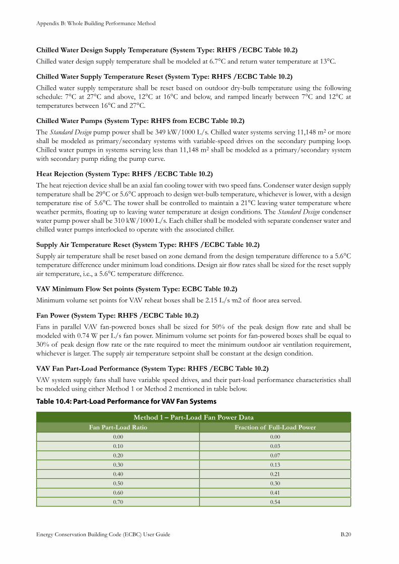
Appendix B: Whole Building Performance Method
Energy Conservation Building Code (ECBC) User Guide B.20
Chilled Water Design Supply Temperature (System Type: RHFS /ECBC Table 10.2)
Chilled water design supply temperature shall be modeled at 6.7°C and return water temperature at 13°C.
Chilled Water Supply Temperature Reset (System Type: RHFS /ECBC Table 10.2)
Chilled water supply temperature shall be reset based on outdoor dry-bulb temperature using the following schedule: 7°C at 27°C and above, 12°C at 16°C and below, and ramped linearly between 7°C and 12°C at temperatures between 16°C and 27°C.
Chilled Water Pumps (System Type: RHFS from ECBC Table 10.2)
The Standard Design pump power shall be 349 kW/1000 L/s. Chilled water systems serving 11,148 m2 or more shall be modeled as primary/secondary systems with variable-speed drives on the secondary pumping loop. Chilled water pumps in systems serving less than 11,148 m2 shall be modeled as a primary/secondary system with secondary pump riding the pump curve.
Heat Rejection (System Type: RHFS /ECBC Table 10.2)
The heat rejection device shall be an axial fan cooling tower with two speed fans. Condenser water design supply temperature shall be 29°C or 5.6°C approach to design wet-bulb temperature, whichever is lower, with a design temperature rise of 5.6°C. The tower shall be controlled to maintain a 21°C leaving water temperature where weather permits, floating up to leaving water temperature at design conditions. The Standard Design condenser water pump power shall be 310 kW/1000 L/s. Each chiller shall be modeled with separate condenser water and chilled water pumps interlocked to operate with the associated chiller.
Supply Air Temperature Reset (System Type: RHFS /ECBC Table 10.2)
Supply air temperature shall be reset based on zone demand from the design temperature difference to a 5.6°C temperature difference under minimum load conditions. Design air flow rates shall be sized for the reset supply air temperature, i.e., a 5.6°C temperature difference.
VAV Minimum Flow Set points (System Type: ECBC Table 10.2)
Minimum volume set points for VAV reheat boxes shall be 2.15 L/s·m2 of floor area served.
Fan Power (System Type: RHFS /ECBC Table 10.2)
Fans in parallel VAV fan-powered boxes shall be sized for 50% of the peak design flow rate and shall be modeled with 0.74 W per L/s fan power. Minimum volume set points for fan-powered boxes shall be equal to 30% of peak design flow rate or the rate required to meet the minimum outdoor air ventilation requirement, whichever is larger. The supply air temperature setpoint shall be constant at the design condition.
VAV Fan Part-Load Performance (System Type: RHFS /ECBC Table 10.2)
VAV system supply fans shall have variable speed drives, and their part-load performance characteristics shall be modeled using either Method 1 or Method 2 mentioned in table below.
: Part-Load Performance for VAV Fan SystemsTable 10.4
Method 1 – Part-Load Fan Power DataFan Part-Load Ratio Fraction of Full-Load Power
0.00 0.00
0.10 0.03
0.20 0.07
0.30 0.13
0.40 0.21
0.50 0.30
0.60 0.41
0.70 0.54
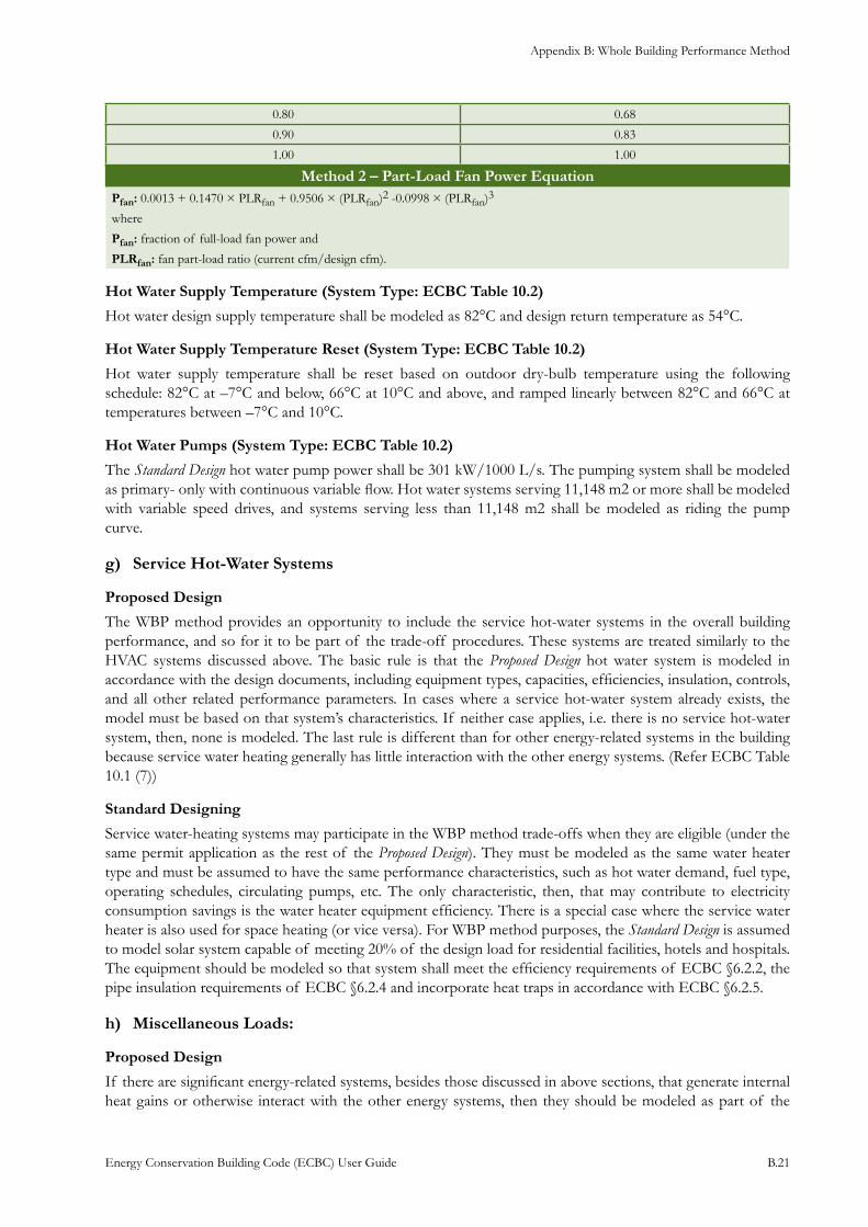
Appendix B: Whole Building Performance Method
Energy Conservation Building Code (ECBC) User Guide B.21
0.80 0.68
0.90 0.83
1.00 1.00
Method 2 – Part-Load Fan Power Equation Pfan: 0.0013 + 0.1470 × PLRfan + 0.9506 × (PLRfan)2 -0.0998 × (PLRfan)3
where
Pfan: fraction of full-load fan power and
PLRfan: fan part-load ratio (current cfm/design cfm).
Hot Water Supply Temperature (System Type: ECBC Table 10.2)
Hot water design supply temperature shall be modeled as 82°C and design return temperature as 54°C.
Hot Water Supply Temperature Reset (System Type: ECBC Table 10.2)
Hot water supply temperature shall be reset based on outdoor dry-bulb temperature using the following schedule: 82°C at –7°C and below, 66°C at 10°C and above, and ramped linearly between 82°C and 66°C at temperatures between –7°C and 10°C.
Hot Water Pumps (System Type: ECBC Table 10.2)
The Standard Design hot water pump power shall be 301 kW/1000 L/s. The pumping system shall be modeled as primary- only with continuous variable flow. Hot water systems serving 11,148 m2 or more shall be modeled with variable speed drives, and systems serving less than 11,148 m2 shall be modeled as riding the pump curve.
Service Hot-Water Systemsg)
Proposed Design
The WBP method provides an opportunity to include the service hot-water systems in the overall building performance, and so for it to be part of the trade-off procedures. These systems are treated similarly to the HVAC systems discussed above. The basic rule is that the Proposed Design hot water system is modeled in accordance with the design documents, including equipment types, capacities, efficiencies, insulation, controls, and all other related performance parameters. In cases where a service hot-water system already exists, the model must be based on that system’s characteristics. If neither case applies, i.e. there is no service hot-water system, then, none is modeled. The last rule is different than for other energy-related systems in the building because service water heating generally has little interaction with the other energy systems. (Refer ECBC Table 10.1 (7))
Standard Designing
Service water-heating systems may participate in the WBP method trade-offs when they are eligible (under the same permit application as the rest of the Proposed Design). They must be modeled as the same water heater type and must be assumed to have the same performance characteristics, such as hot water demand, fuel type, operating schedules, circulating pumps, etc. The only characteristic, then, that may contribute to electricity consumption savings is the water heater equipment efficiency. There is a special case where the service water heater is also used for space heating (or vice versa). For WBP method purposes, the Standard Design is assumed to model solar system capable of meeting 20% of the design load for residential facilities, hotels and hospitals. The equipment should be modeled so that system shall meet the efficiency requirements of ECBC §6.2.2, the pipe insulation requirements of ECBC §6.2.4 and incorporate heat traps in accordance with ECBC §6.2.5.
Miscellaneous Loads: h)
Proposed Design
If there are significant energy-related systems, besides those discussed in above sections, that generate internal heat gains or otherwise interact with the other energy systems, then they should be modeled as part of the
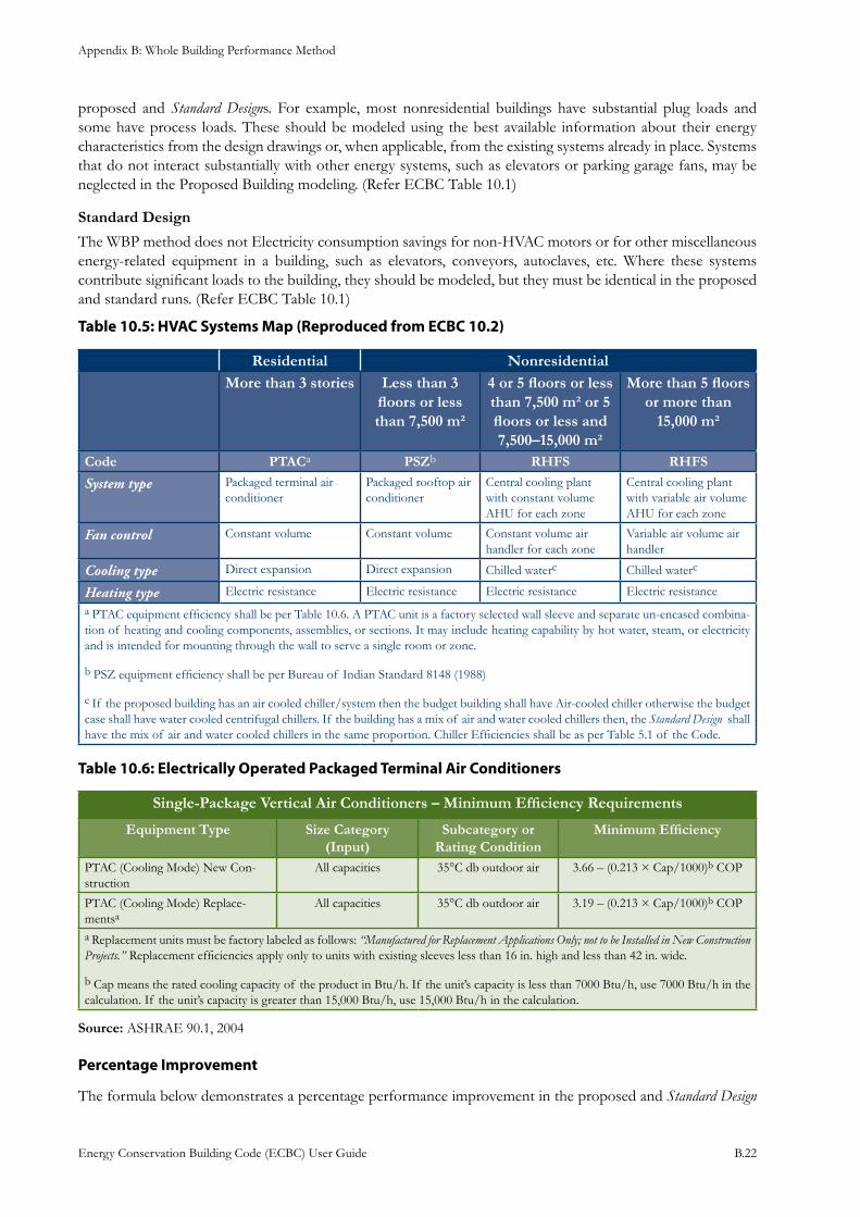
Appendix B: Whole Building Performance Method
Energy Conservation Building Code (ECBC) User Guide B.22
proposed and Standard Designs. For example, most nonresidential buildings have substantial plug loads and some have process loads. These should be modeled using the best available information about their energy characteristics from the design drawings or, when applicable, from the existing systems already in place. Systems that do not interact substantially with other energy systems, such as elevators or parking garage fans, may be neglected in the Proposed Building modeling. (Refer ECBC Table 10.1)
Standard Design
The WBP method does not Electricity consumption savings for non-HVAC motors or for other miscellaneous energy-related equipment in a building, such as elevators, conveyors, autoclaves, etc. Where these systems contribute significant loads to the building, they should be modeled, but they must be identical in the proposed and standard runs. (Refer ECBC Table 10.1)
: HVAC Systems Map (Reproduced from ECBC 10.2) Table 10.5
Residential NonresidentialMore than 3 stories Less than 3
floors or less than 7,500 m²
4 or 5 floors or less than 7,500 m² or 5 floors or less and 7,500–15,000 m²
More than 5 floors or more than
15,000 m²
Code PTACa PSZb RHFS RHFS
System type Packaged terminal air conditioner
Packaged rooftop air conditioner
Central cooling plant with constant volume AHU for each zone
Central cooling plant with variable air volume AHU for each zone
Fan control Constant volume Constant volume Constant volume air handler for each zone
Variable air volume air handler
Cooling type Direct expansion Direct expansion Chilled waterc Chilled waterc
Heating type Electric resistance Electric resistance Electric resistance Electric resistance
a PTAC equipment efficiency shall be per Table 10.6. A PTAC unit is a factory selected wall sleeve and separate un-encased combina-tion of heating and cooling components, assemblies, or sections. It may include heating capability by hot water, steam, or electricity and is intended for mounting through the wall to serve a single room or zone.
b PSZ equipment efficiency shall be per Bureau of Indian Standard 8148 (1988)
c If the proposed building has an air cooled chiller/system then the budget building shall have Air-cooled chiller otherwise the budget case shall have water cooled centrifugal chillers. If the building has a mix of air and water cooled chillers then, the Standard Design shall have the mix of air and water cooled chillers in the same proportion. Chiller Efficiencies shall be as per Table 5.1 of the Code.
: Electrically Operated Packaged Terminal Air ConditionersTable 10.6
Single-Package Vertical Air Conditioners – Minimum Efficiency Requirements
Equipment Type Size Category (Input)
Subcategory or Rating Condition
Minimum Efficiency
PTAC (Cooling Mode) New Con-struction
All capacities 35°C db outdoor air 3.66 – (0.213 × Cap/1000)b COP
PTAC (Cooling Mode) Replace-mentsa
All capacities 35°C db outdoor air 3.19 – (0.213 × Cap/1000)b COP
a Replacement units must be factory labeled as follows: “Manufactured for Replacement Applications Only; not to be Installed in New Construction Projects.” Replacement efficiencies apply only to units with existing sleeves less than 16 in. high and less than 42 in. wide.
b Cap means the rated cooling capacity of the product in Btu/h. If the unit’s capacity is less than 7000 Btu/h, use 7000 Btu/h in the calculation. If the unit’s capacity is greater than 15,000 Btu/h, use 15,000 Btu/h in the calculation.
Source: ASHRAE 90.1, 2004
Percentage Improvement
The formula below demonstrates a percentage performance improvement in the proposed and Standard Design
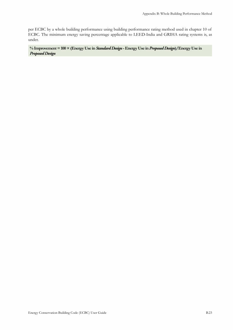
Appendix B: Whole Building Performance Method
Energy Conservation Building Code (ECBC) User Guide B.23
per ECBC by a whole building performance using building performance rating method used in chapter 10 of ECBC. The minimum energy saving percentage applicable to LEED-India and GRIHA rating systems is, as under.
% Improvement = 100 × (Energy Use in Standard Design - Energy Use in Proposed Design)/Energy Use in Proposed Design
Appendix B: Whole Building Performance Method
Energy Conservation Building Code (ECBC) User Guide B.24
Case StudyTo demonstrate ECBC compliance for building design using WBP method, building energy simulation models need to be developed. This document uses two important terms to understand the process – Standard Design and the Proposed Design. To evaluate energy performance of the Proposed Design and to see if it is compliant with ECBC, one needs to build a hypothetical simulation model based on the methodology described in Appendix B of the Guide (also explained in this Guide). This hypothetical model is called Standard Design. Sometimes Standard Design is also referred to as “Base Case”. Energy consumption in the Standard Design is compared with the energy consumption in the Proposed Design. If the energy consumption in the Proposed Design is more than that of the Standard Design, one needs to incorporate energy conservation measures (ECMs) to improve the energy performance of the Proposed Design for achieving ECBC compliance. Hence in this case study after analyzing the design inputs and incorporating the ECMs, the Proposed Design model has been created. The process of creating the Standard Design model and the Proposed Design model, their inputs for simulations and their results are discussed and explained in this case study. The hypothetical building used in the case study is located in Ahmedabad, Gujarat, India.
The steps involved for ECBC compliance using WBP method are:
Ensure that the building design conforms to the local building bye laws and regulations1.
Comply with the mandatory requirements of the ECBC2.
Create the 3. Proposed Design model
Create the 4. Standard Design model
Compare the energy consumption of the 5. Proposed Design with that of the Standard Design
If the energy consumption of the 6. Proposed Design is more than that of Standard Design, incorporate additional ECMs in the Proposed Design
Ensure that the 7. Standard Design created in Step 4 is still valid. If necessary, revise the Standard Design
Repeat step 5 through 7 till energy consumption in the 8. Proposed Design is less than or equal to the energy consumption in Standard Design
Prepare the compliance documents9.
All the above steps are dealt with in detail in this chapter.
Before commencing with the data input process for the model, the project should refer to Appendix E - Climate Zone Map of India in the Code to check the climate zone in which the site is located. The Guide also lists various cities and their corresponding climate zones. Weather files for 58 cities from India are available at: http://www.eere.energy.gov/buildings/energyplus/cfm/weather_data3.cfm/region=2_asia_wmo_region_2/country=IND/cname=India. This weather data is ready to be used in EnergyPlus simulation software but can be customized for other simulation tools using appropriate weather file converter program. The building proposed for the case study is in Ahmedabad, which is classified under hot and dry climate.
The building should then be classified either as a 24-hour activity building or a daytime activity building because the ECBC specifications for the U-factors of the building envelope are mandated according to the climate zone and the occupancy type of the building.
However, before going into the details of ECBC compliance, it is necessary to describe the case study used for demonstration.
Building Description
The building proposed for the case study is in Ahmedabad, which is classified under hot and dry climate a.
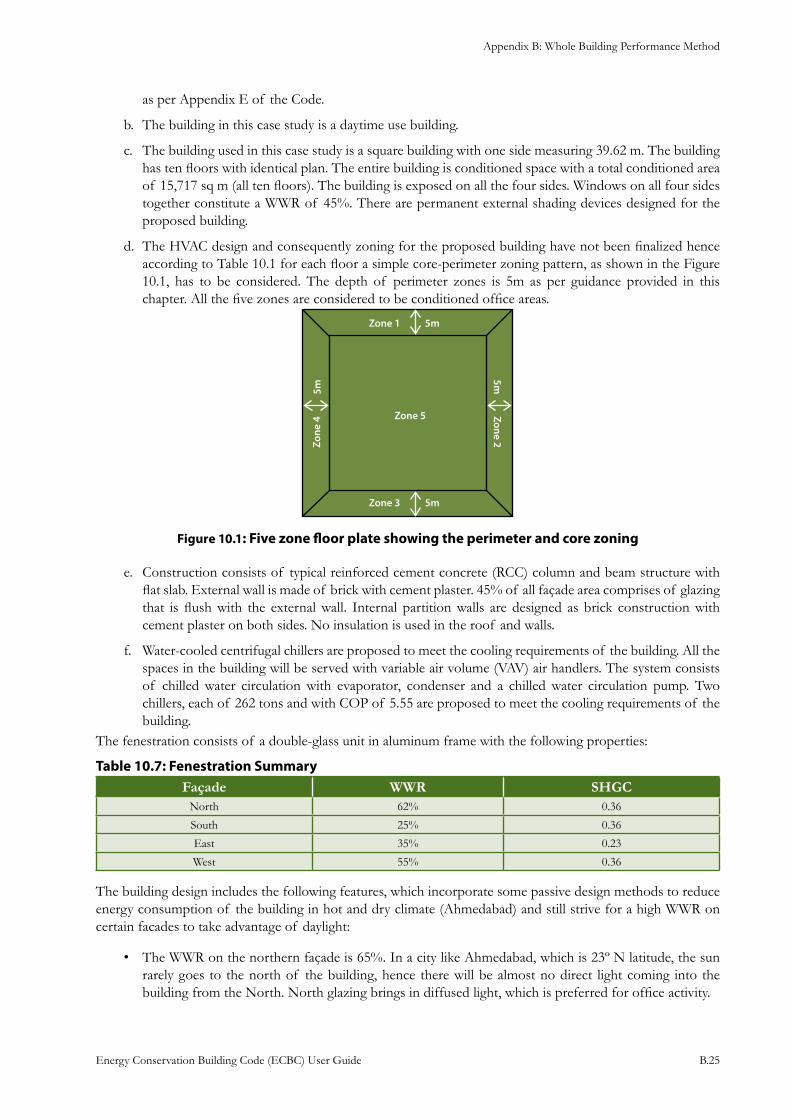
Appendix B: Whole Building Performance Method
Energy Conservation Building Code (ECBC) User Guide B.25
as per Appendix E of the Code.
The building in this case study is a daytime use building.b.
The building used in this case study is a square building with one side measuring 39.62 m. The building c. has ten floors with identical plan. The entire building is conditioned space with a total conditioned area of 15,717 sq m (all ten floors). The building is exposed on all the four sides. Windows on all four sides together constitute a WWR of 45%. There are permanent external shading devices designed for the proposed building.
The HVAC design and consequently zoning for the proposed building have not been finalized hence d. according to Table 10.1 for each floor a simple core-perimeter zoning pattern, as shown in the Figure 10.1, has to be considered. The depth of perimeter zones is 5m as per guidance provided in this chapter. All the five zones are considered to be conditioned office areas.
: Five zone floor plate showing the perimeter and core zoningFigure 10.1
Construction consists of typical reinforced cement concrete (RCC) column and beam structure with e. flat slab. External wall is made of brick with cement plaster. 45% of all façade area comprises of glazing that is flush with the external wall. Internal partition walls are designed as brick construction with cement plaster on both sides. No insulation is used in the roof and walls.
Water-cooled centrifugal chillers are proposed to meet the cooling requirements of the building. All the f. spaces in the building will be served with variable air volume (VAV) air handlers. The system consists of chilled water circulation with evaporator, condenser and a chilled water circulation pump. Two chillers, each of 262 tons and with COP of 5.55 are proposed to meet the cooling requirements of the building.
The fenestration consists of a double-glass unit in aluminum frame with the following properties:
: Fenestration SummaryTable 10.7Façade WWR SHGC
North 62% 0.36
South 25% 0.36
East 35% 0.23
West 55% 0.36
The building design includes the following features, which incorporate some passive design methods to reduce energy consumption of the building in hot and dry climate (Ahmedabad) and still strive for a high WWR on certain facades to take advantage of daylight:
The WWR on the northern façade is 65%. In a city like Ahmedabad, which is 23º N latitude, the sun • rarely goes to the north of the building, hence there will be almost no direct light coming into the building from the North. North glazing brings in diffused light, which is preferred for office activity.
Appendix B: Whole Building Performance Method
Energy Conservation Building Code (ECBC) User Guide B.26
The building has a WWR of 25% on the East side and a WWR of 55% on the West side.•
Ahmedabad being in a hot climate, the solar heat gain coefficient of the glass plays an important role. • In this regard, the windows on East façade (where horizontal and vertical shading devices would not be very effective) of the building are proposed with a double glazed unit of low SHGC value of 0.23. Windows on the South, North and West facades have a double glazed unit with SHGC of 0.36.
On the south façade of the building, overhangs of 0.6 m depth have been designed to reduce the direct • light coming inside the building.
To reduce high solar heat gain from the West side, vertical louvers/fins of 0.6 m width at a gap of 1.5 • m are proposed.
To take advantage of the high visible transmittance (0.62) of double glazed unit and high WWR in the • North and the West facades, perimeter zones in these directions are equipped with daylight sensors that can dim the internal lighting in these zones.
Steps for ECBC Compliance
Ensure that the building design conforms to the local building bye laws and regulationsStep 1:
It is recommended to ensure that the building design conforms to the local building bye laws and regulations. The design team should request clear guidance from the local authorities on the following issues:
Applicability of ECBC to the project•
Submittal requirements and procedure to apply for ECBC compliance•
Any local amendments to the ECBC that need to be followed•
Acceptability of the weather file to the authorities•
Comply with the mandatory requirements of the ECBCStep 2:
All the mandatory requirements of the ECBC code must be met by the project. The mandatory provisions of building envelope, HVAC, service hot water and pumping, lighting and electrical power are provided in sections 4.2, 5.2, 6.2, 7.2 and 8.2 respectively of the Code and must be complied with. It should be noted that even if the WBP method is adopted for ECBC compliance, mandatory requirements must still be followed even though one might not follow any or all of the prescriptive requirements.
Create the Proposed Design Simulation ModelStep 3:
The simulation model should be developed as per the Proposed Design guidelines provided in Table 10.1 of the Guide. This table is an updated version of Table 10.1 of ECBC and provides detailed guidance to the users in creating both the Proposed and Standard Design.
This section describes the methodology for creating the Proposed Design simulation model. All the assumptions while creating the model must be stated clearly and unambiguously and the simulation model of the Proposed Design should be prepared using approved simulation software. The simulation software must meet all the specifications listed in Section 10.2.1 of Appendix B of the Code.
Building Envelope
While modeling, the following should be noted:
Walls within 45 degrees of each other can be combined into a single wall and assumed to have one • orientation.
The building in the • Proposed Design case is to be modeled only for the actual designed orientation.
All the building envelope materials in the simulation model shall be as per the • Proposed Design of the
Appendix B: Whole Building Performance Method
Energy Conservation Building Code (ECBC) User Guide B.27
building. Thermal specifications of walls must include thermal mass (specific heat and density) as well as thermal resistance (U-factor or R-value).
In this case study, the external wall section in the • Proposed Design is a 230 mm brick wall with cement plaster on either side. If the manufacturer provides the material properties, they should, after verification, be used to calculate the final U-factor of the construction assembly. However, in this case study it is assumed that no data was available from the manufacturer. Thermo-physical properties of construction materials can be obtained from two sources:
Appendix C of ECBC –
Libraries included in the simulation program –
For this case study, the properties of the specified materials were derived from the simulation software • library, which were assembled to form the building envelope. The resultant U-factor of the wall works out to be 2.02 W/m2·K. Similarly, U-factor of the roof, which is an un-insulated RCC slab, works out to be 1.618 W/m2·K.
While modeling the facades of the building, the windows need to be modeled separately if the building • uses daylight controls. Otherwise they can be combined (if they are in the same zone) into a larger effective window. Manually operated window-shading devices such as blinds or shades should not be modeled. However, any permanent shading devices such as fins, overhangs, and light-shelves have to be modeled as they have significant impact on the overall heat gain as well as daylight in the building. Since, India presently does not have a labeling program certifying the U-factor of the windows, the project’s Proposed Design needs to comply with the requirement of the ECBC (for unrated vertical fenestration) as specified in Table 11.1 of Appendix C. As per this table, the U-factor of the window assembly of the case study model is 5.1 W/m2·K. Manufacturer has however provided the SHGC (0.36 and 0.23 for two types of glazing used in the building) and Visible Light Transmittance values (0.62 and 0.41 for two types of glazing).
For exterior roofs other than roofs with ventilated attics, the reflectance and emittance of the proposed • roof surface, which can be derived from building material specifications, should also be modeled. For the case study, the roof surface has been modeled with a reflectance of 0.45 since the reflectance and emittance of the roof surface is exceeding the Code requirements as specified in Table 10.1 (Building Envelope) of the Guide.
Schedules
Office schedule with varying occupancy from 7 am to 12 mid-night has been proposed for the building. Normal office schedule will be from 9 am to 6pm.
Lighting
For the Proposed Design:
The design electric lighting power should be modeled accurately for the purpose of simulation. •
The lighting system power should include all lighting system components shown or provided for in the • plans (including lamps, ballasts, task fixtures, and furniture-mounted fixtures).
In cases where the electrical design includes lighting controls, they should be included in the simulation • model.
For the case study:
An LPD value of 8.61 W/m2·has been used in the office areas. •
Daylight sensors are proposed in the design of the lighting systems on the North and West facades.•
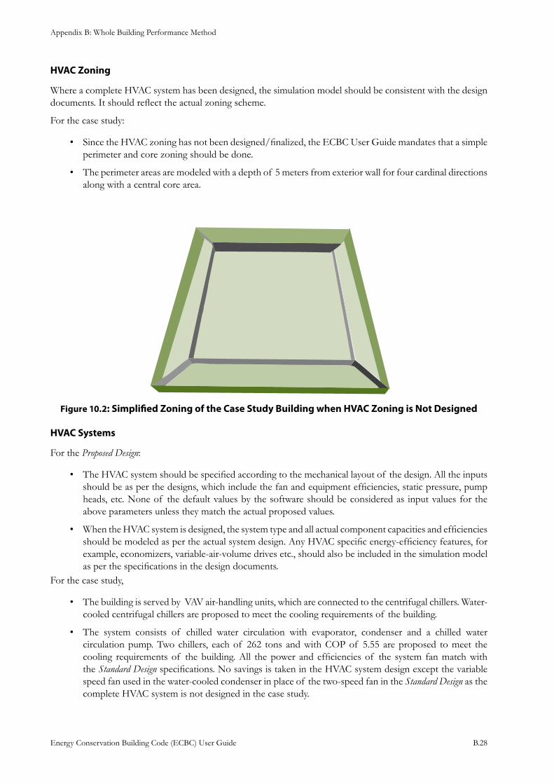
Appendix B: Whole Building Performance Method
Energy Conservation Building Code (ECBC) User Guide B.28
HVAC Zoning
Where a complete HVAC system has been designed, the simulation model should be consistent with the design documents. It should reflect the actual zoning scheme.
For the case study:
Since the HVAC zoning has not been designed/finalized, the ECBC User Guide mandates that a simple • perimeter and core zoning should be done.
The perimeter areas are modeled with a depth of 5 meters from exterior wall for four cardinal directions • along with a central core area.
: Simplified Zoning of the Case Study Building when HVAC Zoning is Not DesignedFigure 10.2
HVAC Systems
For the Proposed Design:
The HVAC system should be specified according to the mechanical layout of the design. All the inputs • should be as per the designs, which include the fan and equipment efficiencies, static pressure, pump heads, etc. None of the default values by the software should be considered as input values for the above parameters unless they match the actual proposed values.
When the HVAC system is designed, the system type and all actual component capacities and efficiencies • should be modeled as per the actual system design. Any HVAC specific energy-efficiency features, for example, economizers, variable-air-volume drives etc., should also be included in the simulation model as per the specifications in the design documents.
For the case study,
The building is served by VAV air-handling units, which are connected to the centrifugal chillers. Water-• cooled centrifugal chillers are proposed to meet the cooling requirements of the building.
The system consists of chilled water circulation with evaporator, condenser and a chilled water • circulation pump. Two chillers, each of 262 tons and with COP of 5.55 are proposed to meet the cooling requirements of the building. All the power and efficiencies of the system fan match with the Standard Design specifications. No savings is taken in the HVAC system design except the variable speed fan used in the water-cooled condenser in place of the two-speed fan in the Standard Design as the complete HVAC system is not designed in the case study.
Appendix B: Whole Building Performance Method
Energy Conservation Building Code (ECBC) User Guide B.29
Miscellaneous Loads
For the case study, an internal equipment load of 21.6 W/m2 has been considered for both the Proposed Design.
Create the Standard Design simulation modelStep 4:
The simulation model should be developed as per the Standard Design guidelines provided in Table 10.1 of the Guide. The Standard Design model is created using the Whole Building Performance method specified in ECBC. Once the model has been created, the simulation runs will show the energy consumption of the Standard Design building.
The Standard Design is created with building specifications that comply with all prescriptive requirements of the ECBC. In the simulation model of the Standard Design, the glazing area is equally distributed on all sides of the building.
For the Standard Design, the energy use shall be generated by simulating the building with its actual orientation and subsequently rotating the building by 90, 180 and 270 degrees. The energy use for the Standard Design will be obtained by taking an average of energy use from the simulation runs for four different orientations.
Site and Climate
All the input parameters in the Standard Design will be same as in the Proposed Design model.
Building Envelope
While modeling, the following should be noted:
Walls: The proposed building has two types of walls: external walls and internal partitions. Walls of the building should be categorized based on their position within the building. Appendix A of the Code, deals with the definitions of various kinds of walls in a building. The wall construction must comply with the prescriptive requirements of Section 4.3.2 of the Code. For the case study, since the building is in hot and dry climate and is a daytime use building, according to Table 4.3.2 of the Code, the U-factor of the wall shall be 0.44 W/m2·K.
Roof: The roof construction must comply with the prescriptive requirements of Section 4.3.1 and 4.3.2 of the Code. For the case study, a mass construction roof with a U-factor of 0.409 W/m2.K has been specified in the Standard Design model. Table 10.1 provides guidance on how to model the reflectivity of the roof.
Windows:
In the Standard Design:
Windows in all the directions have the same prescriptive requirements for SHGC and the U-factor. •
Windows should be equally distributed on all the sides. •
U-factor and the SHGC requirements depend on the window wall ratio (WWR) and the climate zone. •
The U-factor, SHGC and Visible Light Transmittance of the glass must meet the requirements set forth • in Section 4.3.3 of the Code.
Shading should not be modeled, whether internal or external. Self-shading of the building too shouldn’t • be modeled as per Table 10.1 (Building Envelope).
For the case study:
Since the • Proposed Design has a WWR of 45%, as per Table 10.1 (Building Envelope) of the Guide, the WWR in the Standard Design shall be limited to 40%.
All the windows in the • Standard Design shall have a U-factor of 3.3 W/m2.K and SHGC of 0.25 as per Table 4.3 of the Code.
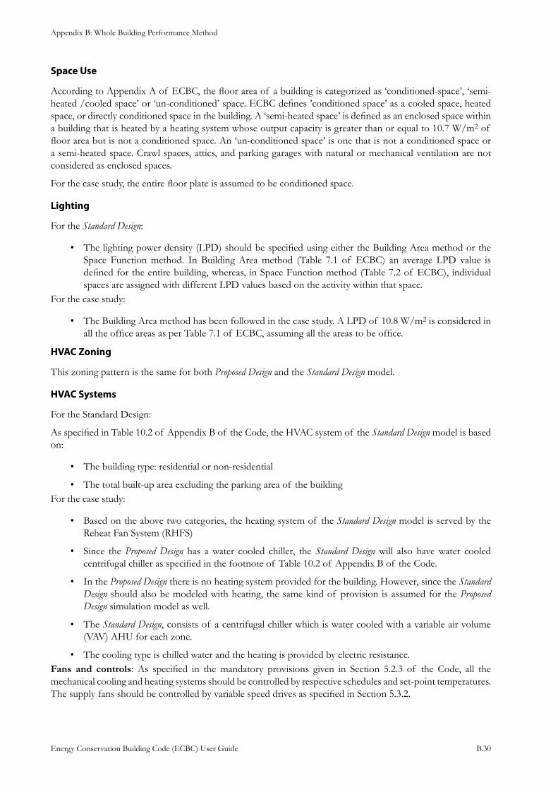
Appendix B: Whole Building Performance Method
Energy Conservation Building Code (ECBC) User Guide B.30
Space Use
According to Appendix A of ECBC, the floor area of a building is categorized as ‘conditioned-space’, ‘semi-heated /cooled space’ or ‘un-conditioned’ space. ECBC defines ’conditioned space’ as a cooled space, heated space, or directly conditioned space in the building. A ‘semi-heated space’ is defined as an enclosed space within a building that is heated by a heating system whose output capacity is greater than or equal to 10.7 W/m2 of floor area but is not a conditioned space. An ‘un-conditioned space’ is one that is not a conditioned space or a semi-heated space. Crawl spaces, attics, and parking garages with natural or mechanical ventilation are not considered as enclosed spaces.
For the case study, the entire floor plate is assumed to be conditioned space.
Lighting
For the Standard Design:
The lighting power density (LPD) should be specified using either the Building Area method or the • Space Function method. In Building Area method (Table 7.1 of ECBC) an average LPD value is defined for the entire building, whereas, in Space Function method (Table 7.2 of ECBC), individual spaces are assigned with different LPD values based on the activity within that space.
For the case study:
The Building Area method has been followed in the case study. A LPD of 10.8 W/m• 2 is considered in all the office areas as per Table 7.1 of ECBC, assuming all the areas to be office.
HVAC Zoning
This zoning pattern is the same for both Proposed Design and the Standard Design model.
HVAC Systems
For the Standard Design:
As specified in Table 10.2 of Appendix B of the Code, the HVAC system of the Standard Design model is based on:
The building type: residential or non-residential•
The total built-up area excluding the parking area of the building• For the case study:
Based on the above two categories, the heating system of the • Standard Design model is served by the Reheat Fan System (RHFS)
Since the • Proposed Design has a water cooled chiller, the Standard Design will also have water cooled centrifugal chiller as specified in the footnote of Table 10.2 of Appendix B of the Code.
In the • Proposed Design there is no heating system provided for the building. However, since the Standard Design should also be modeled with heating, the same kind of provision is assumed for the Proposed Design simulation model as well.
The • Standard Design, consists of a centrifugal chiller which is water cooled with a variable air volume (VAV) AHU for each zone.
The cooling type is chilled water and the heating is provided by electric resistance.• Fans and controls: As specified in the mandatory provisions given in Section 5.2.3 of the Code, all the mechanical cooling and heating systems should be controlled by respective schedules and set-point temperatures. The supply fans should be controlled by variable speed drives as specified in Section 5.3.2.
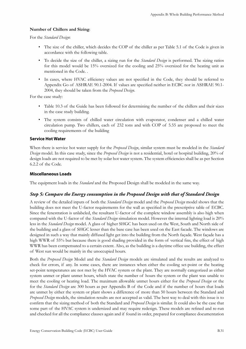
Appendix B: Whole Building Performance Method
Energy Conservation Building Code (ECBC) User Guide B.31
Number of Chillers and Sizing:
For the Standard Design:
The size of the chiller, which decides the COP of the chiller as per Table 5.1 of the Code is given in • accordance with the following table.
To decide the size of the chiller, a sizing run for the • Standard Design is performed. The sizing ratios for this model would be 15% oversized for the cooling and 25% oversized for the heating unit as mentioned in the Code. .
In cases, where HVAC efficiency values are not specified in the Code, they should be referred to • Appendix Go of ASHRAE 90.1-2004. If values are specified neither in ECBC nor in ASHRAE 90.1-2004, they should be taken from the Proposed Design.
For the case study:
• Table 10.3 of the Guide has been followed for determining the number of the chillers and their sizes in the case study building.
The system consists of chilled water circulation with evaporator, condenser and a chilled water • circulation pump. Two chillers, each of 232 tons and with COP of 5.55 are proposed to meet the cooling requirements of the building
Service Hot Water
When there is service hot water supply for the Proposed Design, similar system must be modeled in the Standard Design model. In this case study, since the Proposed Design is not a residential, hotel or hospital building, 20% of design loads are not required to be met by solar hot water system. The system efficiencies shall be as per Section 6.2.2 of the Code.
Miscellaneous Loads
The equipment loads in the Standard and the Proposed Design shall be modeled in the same way.
Compare the Energy consumption in the Proposed Design with that of Standard DesignStep 5:
A review of the detailed inputs of both the Standard Design model and the Proposed Design model shows that the building does not meet the U-factor requirements for the wall as specified in the prescriptive table of ECBC. Since the fenestration is unlabeled, the resultant U-factor of the complete window assembly is also high when compared with the U-factor of the Standard Design simulation model. However the internal lighting load is 20% less in the Standard Design model. A glass of higher SHGC has been used on the West, South and North side of the building and a glass of SHGC lesser than the base case has been used on the East facade. The windows are designed in such a way that mainly diffused light get into the building from the North façade. West façade has a high WWR of 55% but because there is good shading provided in the form of vertical fins, the effect of high WWR has been compensated to a certain extent. Also, as the building is a daytime office use building, the effect of West sun would be mainly in the unoccupied hours.
Both the Proposed Design Model and the Standard Design models are simulated and the results are analyzed to check for errors, if any. In some cases, there are instances when either the cooling set-point or the heating set-point temperatures are not met by the HVAC system or the plant. They are normally categorized as either system unmet or plant unmet hours, which state the number of hours the system or the plant was unable to meet the cooling or heating load. The maximum allowable unmet hours either for the Proposed Design or the for the Standard Design are 300 hours as per Appendix B of the Code and if the number of hours that loads are unmet by either the system or plant shows a difference of more than 50 hours between the Standard and Proposed Design models, the simulation results are not accepted as valid. The best way to deal with this issue is to confirm that the sizing method of both the Standard and Proposed Design is similar. It could also be the case that some part of the HVAC system is undersized and may require redesign. These models are refined and re-run and checked for all the compliance clauses again and if found in order, prepared for compliance documentation
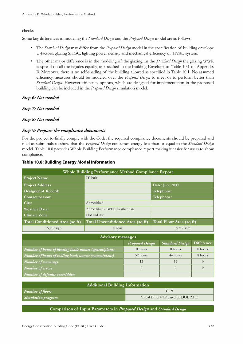
Appendix B: Whole Building Performance Method
Energy Conservation Building Code (ECBC) User Guide B.32
checks.
Some key differences in modeling the Standard Design and the Proposed Design model are as follows:
The • Standard Design may differ from the Proposed Design model in the specification of building envelope U-factors, glazing SHGC, lighting power density and mechanical efficiency of HVAC system.
The other major difference is in the modeling of the glazing. In the • Standard Design the glazing WWR is spread on all the façades equally, as specified in the Building Envelope of Table 10.1 of Appendix B. Moreover, there is no self-shading of the building allowed as specified in Table 10.1. No assumed efficiency measures should be modeled over the Proposed Design to meet or to perform better than Standard Design. However efficiency options, which are designed for implementation in the proposed building can be included in the Proposed Design simulation model.
Not neededStep 6:
Not neededStep 7:
Not neededStep 8:
Prepare the compliance documentsStep 9:
For the project to finally comply with the Code, the required compliance documents should be prepared and filed as submittals to show that the Proposed Design consumes energy less than or equal to the Standard Design model. Table 10.8 provides Whole Building Performance compliance report making it easier for users to show compliance.
: Building Energy Model InformationTable 10.8
Whole Building Performance Method Compliance ReportProject Name IT Park
Project Address Date: June 2009Designer of Record: Telephone: Contact person: Telephone:
City: Ahmedabad
Weather Data: Ahmedabad - IWEC weather data
Climate Zone: Hot and dry
Total Conditioned Area (sq ft) Total Unconditioned Area (sq ft) Total Floor Area (sq ft)15,717 sqm 0 sqm 15,717 sqm
Advisory messagesProposed Design Standard Design Difference
Number of hours of heating loads unmet (system/plant) 0 hours 0 hours 0 hours
Number of hours of cooling loads unmet (system/plant) 52 hours 44 hours 8 hours
Number of warnings 12 12 0
Number of errors 0 0 0
Number of defaults overridden
Additional Building InformationNumber of floors G+9
Simulation program Visual DOE 4.1.2 based on DOE 2.1 E
Comparison of Input Parameters in Proposed Design and Standard Design
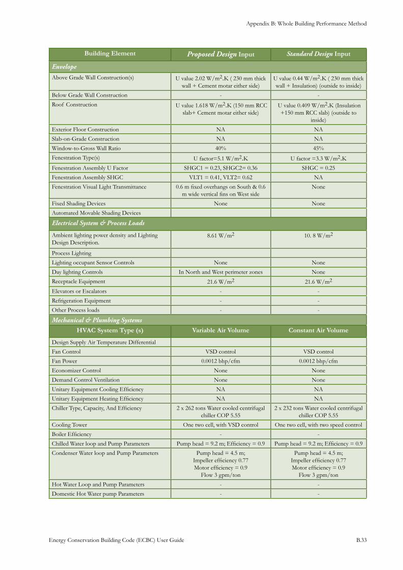
Appendix B: Whole Building Performance Method
Energy Conservation Building Code (ECBC) User Guide B.33
Building Element Proposed Design Input Standard Design Input
Envelope
Above Grade Wall Construction(s) U value 2.02 W/m2.K ( 230 mm thick wall + Cement motar either side)
U value 0.44 W/m2.K ( 230 mm thick wall + Insulation) (outside to inside)
Below Grade Wall Construction - -
Roof Construction U value 1.618 W/m2.K (150 mm RCC slab+ Cement motar either side)
U value 0.409 W/m2.K (Insulation +150 mm RCC slab) (outside to
inside)
Exterior Floor Construction NA NA
Slab-on-Grade Construction NA NA
Window-to-Gross Wall Ratio 40% 45%
Fenestration Type(s) U factor=5.1 W/m2.K U factor =3.3 W/m2.KFenestration Assembly U Factor SHGC1 = 0.23, SHGC2= 0.36 SHGC = 0.25
Fenestration Assembly SHGC VLT1 = 0.41, VLT2= 0.62 NA
Fenestration Visual Light Transmittance 0.6 m fixed overhangs on South & 0.6 m wide vertical fins on West side
None
Fixed Shading Devices None None
Automated Movable Shading Devices
Electrical System & Process Loads
Ambient lighting power density and Lighting Design Description.
8.61 W/m2 10. 8 W/m2
Process Lighting
Lighting occupant Sensor Controls None None
Day lighting Controls In North and West perimeter zones None
Receptacle Equipment 21.6 W/m2 21.6 W/m2
Elevators or Escalators - -
Refrigeration Equipment - -
Other Process loads - -
Mechanical & Plumbing Systems
HVAC System Type (s) Variable Air Volume Constant Air Volume
Design Supply Air Temperature Differential
Fan Control VSD control VSD control
Fan Power 0.0012 bhp/cfm 0.0012 bhp/cfm
Economizer Control None None
Demand Control Ventilation None None
Unitary Equipment Cooling Efficiency NA NA
Unitary Equipment Heating Efficiency NA NA
Chiller Type, Capacity, And Efficiency 2 x 262 tons Water cooled centrifugal chiller COP 5.55
2 x 232 tons Water cooled centrifugal chiller COP 5.55
Cooling Tower One two cell, with VSD control One two cell, with two speed control
Boiler Efficiency - -
Chilled Water loop and Pump Parameters Pump head = 9.2 m; Efficiency = 0.9 Pump head = 9.2 m; Efficiency = 0.9
Condenser Water loop and Pump Parameters Pump head = 4.5 m; Impeller efficiency 0.77 Motor efficiency = 0.9
Flow 3 gpm/ton
Pump head = 4.5 m; Impeller efficiency 0.77 Motor efficiency = 0.9
Flow 3 gpm/ton
Hot Water Loop and Pump Parameters - -
Domestic Hot Water pump Parameters - -
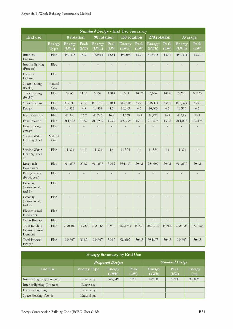
Appendix B: Whole Building Performance Method
Energy Conservation Building Code (ECBC) User Guide B.34
Standard Design - End Use SummaryEnd use 0 rotation 90 rotation 180 rotation 270 rotation Average
Energy Type
Energy (kWh)
Peak (kW)
Energy (kWh)
Peak (kW)
Energy (kWh)
Peak (kW)
Energy (kWh)
Peak (kW)
Energy (kWh)
Peak (kW)
Interiors Lighting
Elec 492,303 152.1 492303 152.1 492303 152.1 492303 152.1 492,303 152.1
Interior lighting (Process)
Elec - - -- - - - - - - -
Exterior Lighting
Elec
Space heating (Fuel 1)
Natural Gas
- - - - - - - - - -
Space heating (Fuel 2)
Elec 3,065 110.1 3,252 108.4 3,389 109.7 3,164 108.8 3,218 109.25
Space Cooling Elec 817,716 338.1 815,756 338.1 815,690 338.1 816,411 338.1 816,393 338.1
Pumps Elec 10,922 4.5 10,894 4.5 10,893 4.5 10,903 4.5 10,903 4.5
Heat Rejection Elec 44,840 16.2 44,766 16.2 44,768 16.2 44,776 16.2 447,88 16.2
Fans Interior Elec 261,403 163.2 260,962 163.2 260,769 163.1 261,215 163.2 261,087 163.175
Fans Parking garage
Elec - - - - - - - - - -
Service Water Heating (Fuel 1)
Natural Gas
- - - - - - - - - -
Service Water Heating (Fuel 2)
Elec 11,324 4.4 11,324 4.4 11,324 4.4 11,324 4.4 11,324 4.4
Receptacle Equipment
Elec 984,607 304.2 984,607 304.2 984,607 304.2 984,607 304.2 984,607 304.2
Refrigeration (Food, etc.,)
Elec - - - - - - - - - -
Cooking (commercial, fuel 1)
Elec - - - - - - - - - -
Cooking (commercial, fuel 2)
Elec - - - - - - - - - -
Elevators and Escalators
Elec - - - - - - - - - -
Other Process Elec - - - - - - - - - -
Total Building Consumption/Demand
Elec 2626180 1092.8 2623864 1091.1 2623743 1092.3 2624703 1091.5 2624623 1091.925
Total Process Energy
Elec 984607 304.2 984607 304.2 984607 304.2 984607 304.2 984607 304.2
Energy Summary by End Use
Proposed Design Standard Design
End Use Energy Type Energy (kWh)
Peak (kW)
Energy (kWh)
Peak (kW)
Energy (%)
Interior Lighting (Ambient) Electricity 328,049 97.9 492,303 152.1 33.36%
Interior lighting (Process) Electricity
Exterior Lighting Electricity
Space Heating (fuel 1) Natural gas
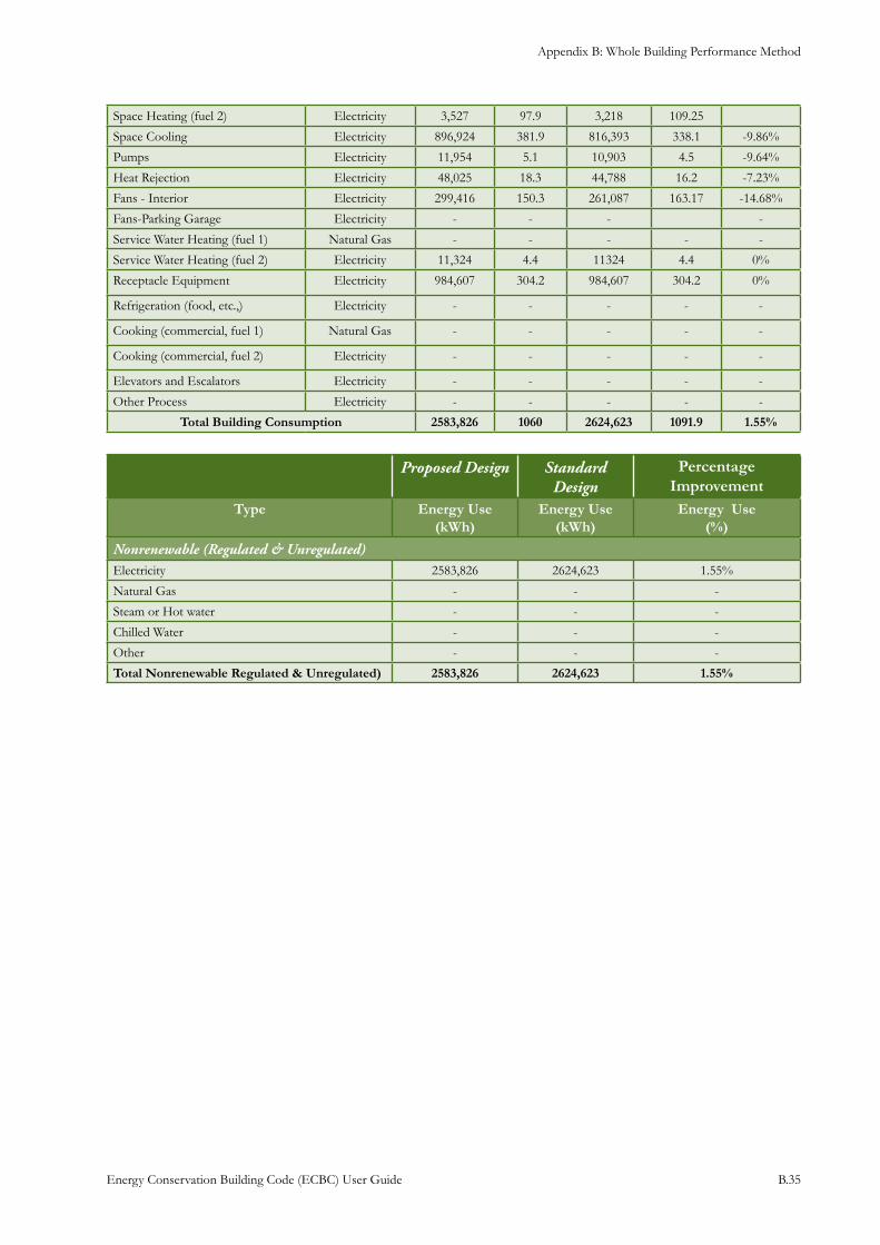
Appendix B: Whole Building Performance Method
Energy Conservation Building Code (ECBC) User Guide B.35
Space Heating (fuel 2) Electricity 3,527 97.9 3,218 109.25
Space Cooling Electricity 896,924 381.9 816,393 338.1 -9.86%
Pumps Electricity 11,954 5.1 10,903 4.5 -9.64%
Heat Rejection Electricity 48,025 18.3 44,788 16.2 -7.23%
Fans - Interior Electricity 299,416 150.3 261,087 163.17 -14.68%
Fans-Parking Garage Electricity - - - -
Service Water Heating (fuel 1) Natural Gas - - - - -
Service Water Heating (fuel 2) Electricity 11,324 4.4 11324 4.4 0%
Receptacle Equipment Electricity 984,607 304.2 984,607 304.2 0%
Refrigeration (food, etc.,) Electricity - - - - -
Cooking (commercial, fuel 1) Natural Gas - - - - -
Cooking (commercial, fuel 2) Electricity - - - - -
Elevators and Escalators Electricity - - - - -
Other Process Electricity - - - - -
Total Building Consumption 2583,826 1060 2624,623 1091.9 1.55%
Proposed Design Standard Design
Percentage Improvement
Type Energy Use (kWh)
Energy Use (kWh)
Energy Use (%)
Nonrenewable (Regulated & Unregulated)Electricity 2583,826 2624,623 1.55%
Natural Gas - - -
Steam or Hot water - - -
Chilled Water - - -
Other - - -
Total Nonrenewable Regulated & Unregulated) 2583,826 2624,623 1.55%
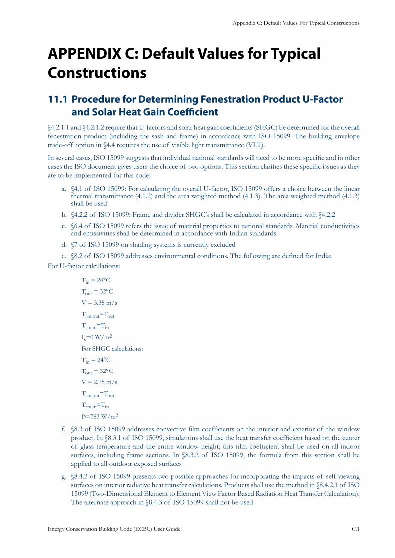
Appendix C: Default Values For Typical Constructions
Energy Conservation Building Code (ECBC) User Guide C.1
APPENDIX C: Default Values for Typical Constructions
Procedure for Determining Fenestration Product U-Factor 11.1 and Solar Heat Gain Coefficient
§4.2.1.1 and §4.2.1.2 require that U-factors and solar heat gain coefficients (SHGC) be determined for the overall fenestration product (including the sash and frame) in accordance with ISO 15099. The building envelope trade-off option in §4.4 requires the use of visible light transmittance (VLT).
In several cases, ISO 15099 suggests that individual national standards will need to be more specific and in other cases the ISO document gives users the choice of two options. This section clarifies these specific issues as they are to be implemented for this code:
§4.1 of ISO 15099: For calculating the overall U-factor, ISO 15099 offers a choice between the linear a. thermal transmittance (4.1.2) and the area weighted method (4.1.3). The area weighted method (4.1.3) shall be used
§4.2.2 of ISO 15099: Frame and divider SHGC’s shall be calculated in accordance with §4.2.2b.
§6.4 of ISO 15099 refers the issue of material properties to national standards. Material conductivities c. and emissivities shall be determined in accordance with Indian standards
§7 of ISO 15099 on shading systems is currently excluded d.
§8.2 of ISO 15099 addresses environmental conditions. The following are defined for India:e. For U-factor calculations:
Tin = 24°C
Tout = 32°C
V = 3.35 m/s
Trm,out=Tout
Trm,in=Tin
Is=0 W/m2
For SHGC calculations:
Tin = 24°C
Tout = 32°C
V = 2.75 m/s
Trm,out=Tout
Trm,in=Tin
Is=783 W/m2
§8.3 of ISO 15099 addresses convective film coefficients on the interior and exterior of the window f. product. In §8.3.1 of ISO 15099, simulations shall use the heat transfer coefficient based on the center of glass temperature and the entire window height; this film coefficient shall be used on all indoor surfaces, including frame sections. In §8.3.2 of ISO 15099, the formula from this section shall be applied to all outdoor exposed surfaces
§8.4.2 of ISO 15099 presents two possible approaches for incorporating the impacts of self-viewing g. surfaces on interior radiative heat transfer calculations. Products shall use the method in §8.4.2.1 of ISO 15099 (Two-Dimensional Element to Element View Factor Based Radiation Heat Transfer Calculation). The alternate approach in §8.4.3 of ISO 15099 shall not be used
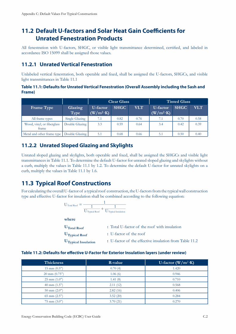
Appendix C: Default Values For Typical Constructions
Energy Conservation Building Code (ECBC) User Guide C.2
Default U-factors and Solar Heat Gain Coefficients for 11.2 Unrated Fenestration Products
All fenestration with U-factors, SHGC, or visible light transmittance determined, certified, and labeled in accordance ISO 15099 shall be assigned those values.
Unrated Vertical Fenestration 11.2.1
Unlabeled vertical fenestration, both operable and fixed, shall be assigned the U-factors, SHGCs, and visible light transmittances in Table 11.1
: Defaults for Unrated Vertical Fenestration (Overall Assembly including the Sash and Table 11.1Frame)
Clear Glass Tinted GlassFrame Type Glazing
Type U-factor
(W/m2·K)SHGC VLT U-factor
(W/m2·K)SHGC VLT
All frame types Single Glazing 7.1 0.82 0.76 7.1 0.70 0.58
Wood, vinyl, or fiberglass frame
Double Glazing 3.3 0.59 0.64 3.4 0.42 0.39
Metal and other frame type Double Glazing 5.1 0.68 0.66 5.1 0.50 0.40
Unrated Sloped Glazing and Skylights11.2.2
Unrated sloped glazing and skylights, both operable and fixed, shall be assigned the SHGCs and visible light transmittances in Table 11.1. To determine the default U-factor for unrated sloped glazing and skylights without a curb, multiply the values in Table 11.1 by 1.2. To determine the default U-factor for unrated skylights on a curb, multiply the values in Table 11.1 by 1.6.
Typical Roof Constructions11.3 For calculating the overall U-factor of a typical roof construction, the U-factors from the typical wall construction type and effective U-factor for insulation shall be combined according to the following equation:
1 1
1UU U
Total Roof
Typical Roof Typical Insulation
=+
where
UTotal Roof : Total U-factor of the roof with insulation
UTypical Roof : U-factor of the roof
UTypical Insulation : U-factor of the effective insulation from Table 11.2
: Defaults for effective U-Factor for Exterior Insulation layers (under review)Table 11.2
Thickness R-value U-factor (W/m2·K)15 mm (0.5”) 0.70 (4) 1.420
20 mm (0.75”) 1.06 (6) 0.946
25 mm (1.0”) 1.41 (8) 0.710
40 mm (1.5”) 2.11 (12) 0.568
50 mm (2.0”) 2.82 (16) 0.406
65 mm (2.5”) 3.52 (20) 0.284
75 mm (3.0”) 3.70 (21) 0.270
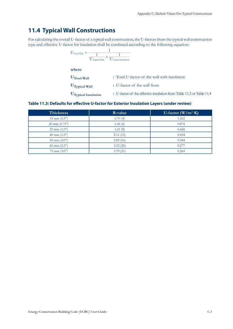
Appendix C: Default Values For Typical Constructions
Energy Conservation Building Code (ECBC) User Guide C.3
Typical Wall Constructions11.4 For calculating the overall U-factor of a typical wall construction, the U-factors from the typical wall construction type and effective U-factor for insulation shall be combined according to the following equation:
UU U
1 11
Total Wall
Typical Wall Typical Insulation
=+
where
UTotal Wall : Total U-factor of the wall with insulation
UTypical Wall : U-factor of the wall from
UTypical Insulation : U-factor of the effective insulation from Table 11.3 or Table 11.4
: Defaults for effective U-factor for Exterior Insulation Layers (under review)Table 11.3
Thickness R-value U-factor (W/m2·K)15 mm (0.5”) 0.70 (4) 1.262
20 mm (0.75”) 1.06 (6) 0.874
25 mm (1.0”) 1.41 (8) 0.668
40 mm (1.5”) 2.11 (12) 0.454
50 mm (2.0”) 2.82 (16) 0.344
65 mm (2.5”) 3.52 (20) 0.277
75 mm (3.0”) 3.70 (21) 0.264
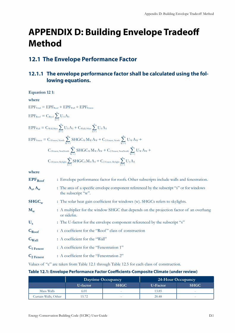
Appendix D: Building Envelope Tradeoff Method
Energy Conservation Building Code (ECBC) User Guide D.1
APPENDIX D: Building Envelope Tradeoff Method
The Envelope Performance Factor 12.1
The envelope performance factor shall be calculated using the fol-12.1.1 lowing equations.
Equation 12 1:
where
EPF EPF EPF EPFTotal Roof Wall Fenest= + +
EPF C U ARoof Roof S SS
n
1=
=/
EPF C U A C U A,,Wall Wall Mass S SS
n
Wall Other S SS
n
11= +
==/ /
EPF C SHGC M A C U A
C SHGC M A C U A
C SHGC M A C U A
,,
,,
,,
Fenest Fenest North W W WW
n
Fenest North W WW
n
Fenest NonNorth W W WW
n
Fenest NonNorth W WW
n
SSStseneFS
n
Fenest S SS
n
thgilykSthgilykS
11
21
11
21
11
21
++=
+ +
+
==
==
==
/ /
/ /
/ /
where
EPFRoof : Envelope performance factor for roofs. Other subscripts include walls and fenestration.
As, Aw : The area of a specific envelope component referenced by the subscript “s” or for windows the subscript “w”.
SHGCw : The solar heat gain coefficient for windows (w). SHGCs refers to skylights.
Mw : A multiplier for the window SHGC that depends on the projection factor of an overhang or sidefin.
Us : The U-factor for the envelope component referenced by the subscript “s”
CRoof : A coefficient for the “Roof ” class of construction
CWall : A coefficient for the “Wall”
C1 Fenest : A coefficient for the “Fenestration 1”
C2 Fenest : A coefficient for the “Fenestration 2”
Values of “c” are taken from Table 12.1 through Table 12.5 for each class of construction.
: Envelope Performance Factor Coefficients-Composite Climate (under review)Table 12.1
Daytime Occupancy 24-Hour OccupancyU-factor SHGC U-Factor SHGC
Mass Walls 6.01 - 13.85 -
Curtain Walls, Other 15.72 - 20.48 -
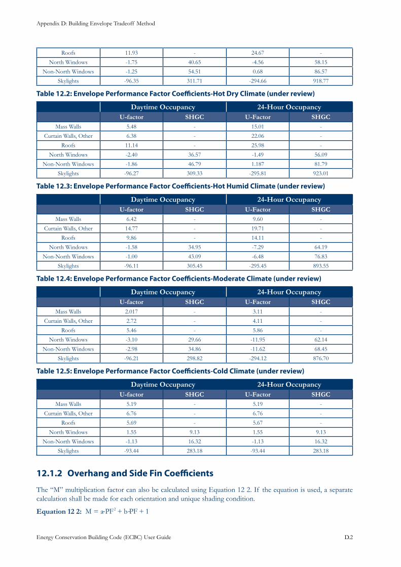
Appendix D: Building Envelope Tradeoff Method
Energy Conservation Building Code (ECBC) User Guide D.2
Roofs 11.93 - 24.67 -
North Windows -1.75 40.65 -4.56 58.15
Non-North Windows -1.25 54.51 0.68 86.57
Skylights -96.35 311.71 -294.66 918.77
: Envelope Performance Factor Coefficients-Hot Dry Climate (under review)Table 12.2
Daytime Occupancy 24-Hour OccupancyU-factor SHGC U-Factor SHGC
Mass Walls 5.48 - 15.01 -
Curtain Walls, Other 6.38 - 22.06 -
Roofs 11.14 - 25.98 -
North Windows -2.40 36.57 -1.49 56.09
Non-North Windows -1.86 46.79 1.187 81.79
Skylights -96.27 309.33 -295.81 923.01
: Envelope Performance Factor Coefficients-Hot Humid Climate (under review)Table 12.3
Daytime Occupancy 24-Hour OccupancyU-factor SHGC U-Factor SHGC
Mass Walls 6.42 - 9.60 -
Curtain Walls, Other 14.77 - 19.71 -
Roofs 9.86 - 14.11 -
North Windows -1.58 34.95 -7.29 64.19
Non-North Windows -1.00 43.09 -6.48 76.83
Skylights -96.11 305.45 -295.45 893.55
: Envelope Performance Factor Coefficients-Moderate Climate (under review)Table 12.4
Daytime Occupancy 24-Hour OccupancyU-factor SHGC U-Factor SHGC
Mass Walls 2.017 - 3.11 -
Curtain Walls, Other 2.72 - 4.11 -
Roofs 5.46 - 5.86 -
North Windows -3.10 29.66 -11.95 62.14
Non-North Windows -2.98 34.86 -11.62 68.45
Skylights -96.21 298.82 -294.12 876.70
: Envelope Performance Factor Coefficients-Cold Climate (under review)Table 12.5
Daytime Occupancy 24-Hour OccupancyU-factor SHGC U-Factor SHGC
Mass Walls 5.19 - 5.19 -
Curtain Walls, Other 6.76 - 6.76 -
Roofs 5.69 - 5.67 -
North Windows 1.55 9.13 1.55 9.13
Non-North Windows -1.13 16.32 -1.13 16.32
Skylights -93.44 283.18 -93.44 283.18
Overhang and Side Fin Coefficients12.1.2
The “M” multiplication factor can also be calculated using Equation 12 2. If the equation is used, a separate calculation shall be made for each orientation and unique shading condition.
Equation 12 2: M a PF b PF 12= + +· ·
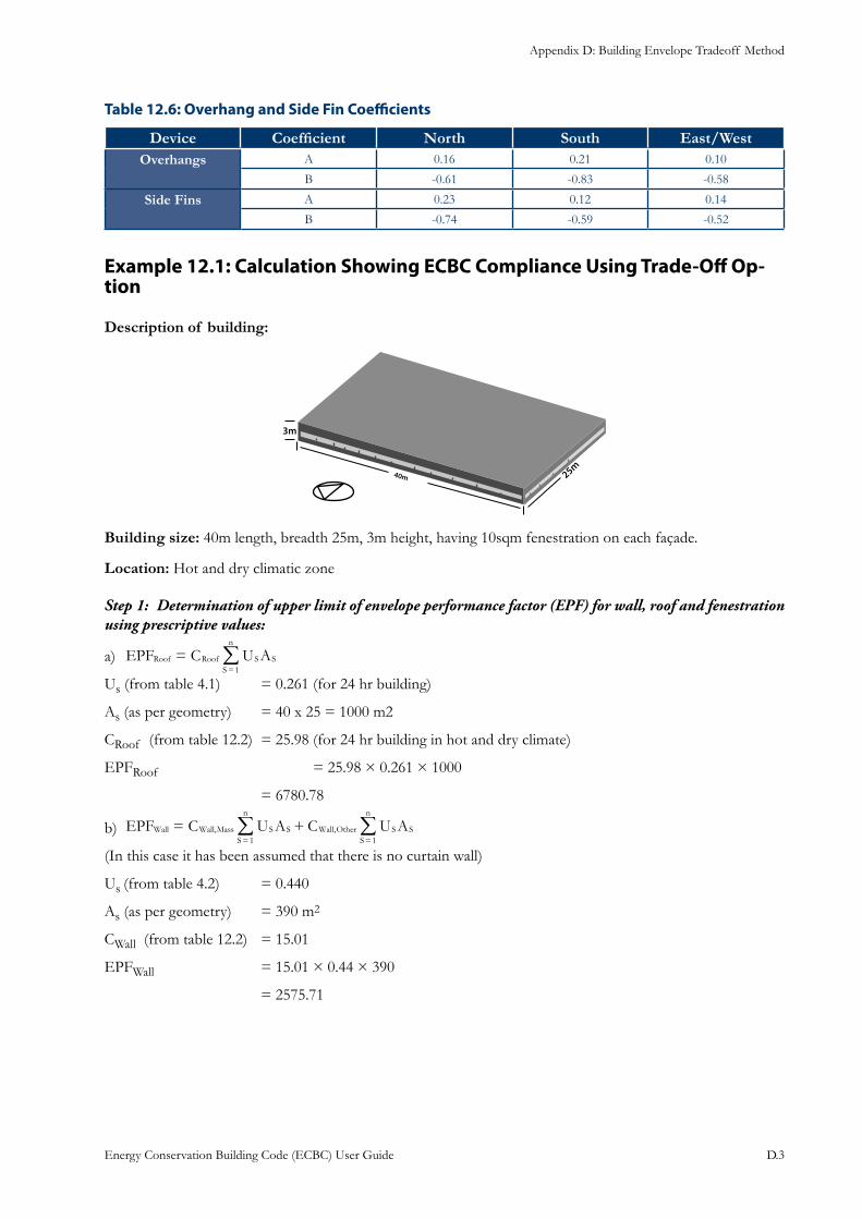
Appendix D: Building Envelope Tradeoff Method
Energy Conservation Building Code (ECBC) User Guide D.3
: Overhang and Side Fin CoefficientsTable 12.6
Device Coefficient North South East/WestOverhangs A 0.16 0.21 0.10
B -0.61 -0.83 -0.58
Side Fins A 0.23 0.12 0.14
B -0.74 -0.59 -0.52
Example 12.1: Calculation Showing ECBC Compliance Using Trade-Off Op-tion
Description of building:
Building size: 40m length, breadth 25m, 3m height, having 10sqm fenestration on each façade.
Location: Hot and dry climatic zone
Determination of upper limit of envelope performance factor (EPF) for wall, roof and fenestration Step 1: using prescriptive values:
EPF C U ARoof Roof S SS
n
1=
=/a)
Us (from table 4.1) = 0.261 (for 24 hr building)
As (as per geometry) = 40 x 25 = 1000 m2
CRoof (from table 12.2) = 25.98 (for 24 hr building in hot and dry climate)
EPFRoof = 25.98 × 0.261 × 1000
= 6780.78
EPF C U A C U A,,Wall Wall Mass S SS
n
Wall Other S SS
n
11= +
==/ /b)
(In this case it has been assumed that there is no curtain wall)
Us (from table 4.2) = 0.440
As (as per geometry) = 390 m2
CWall (from table 12.2) = 15.01
EPFWall = 15.01 × 0.44 × 390
= 2575.71
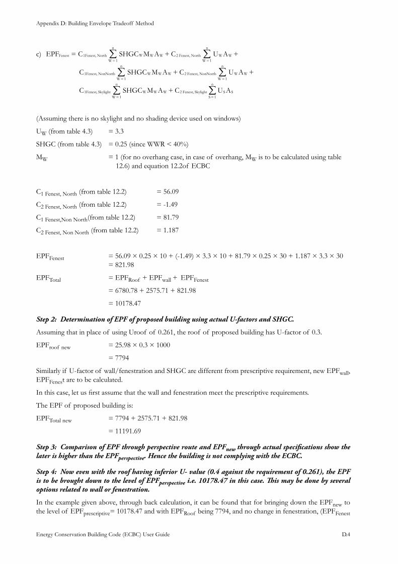
Appendix D: Building Envelope Tradeoff Method
Energy Conservation Building Code (ECBC) User Guide D.4
EPF C SHGC M A C U A
C SHGC M A C U A
C SHGC M A C U A
1 ,1
2 ,1
1 ,1
2 ,1
1 ,1
2 ,1
Fenest Fenest North W W WW
n
Fenest North W WW
n
Fenest NonNorth W W WW
n
Fenest NonNorth W WW
n
Fenest Skylight W W WW
n
Fenest Skylight S SS
n
++=
+ +
+
==
==
==
/ /
/ /
/ /
c)
(Assuming there is no skylight and no shading device used on windows)
UW (from table 4.3) = 3.3
SHGC (from table 4.3) = 0.25 (since WWR < 40%)
MW = 1 (for no overhang case, in case of overhang, MW is to be calculated using table 12.6) and equation 12.2of ECBC
C1 Fenest, North (from table 12.2) = 56.09
C2 Fenest, North (from table 12.2) = -1.49
C1 Fenest,Non North(from table 12.2) = 81.79
C2 Fenest, Non North (from table 12.2) = 1.187
EPFFenest = 56.09 × 0.25 × 10 + (-1.49) × 3.3 × 10 + 81.79 × 0.25 × 30 + 1.187 × 3.3 × 30 = 821.98
EPFTotal = EPFRoof + EPFwall + EPFFenest
= 6780.78 + 2575.71 + 821.98
= 10178.47
Determination of EPF of proposed building using actual U-factors and SHGC.Step 2:
Assuming that in place of using Uroof of 0.261, the roof of proposed building has U-factor of 0.3.
EPFroof new = 25.98 × 0.3 × 1000
= 7794
Similarly if U-factor of wall/fenestration and SHGC are different from prescriptive requirement, new EPFwall, EPFFenest are to be calculated.
In this case, let us first assume that the wall and fenestration meet the prescriptive requirements.
The EPF of proposed building is:
EPFTotal new = 7794 + 2575.71 + 821.98
= 11191.69
Comparison of EPF through perspective route and EPFStep 3: new through actual specifications show the later is higher than the EPFperspective. Hence the building is not complying with the ECBC.
Now even with the roof having inferior U- value (0.4 against the requirement of 0.261), the EPF Step 4: is to be brought down to the level of EPFperspective i.e. 10178.47 in this case. This may be done by several options related to wall or fenestration.
In the example given above, through back calculation, it can be found that for bringing down the EPFnew to the level of EPFprescriptive= 10178.47 and with EPFRoof being 7794, and no change in fenestration, (EPFFenest
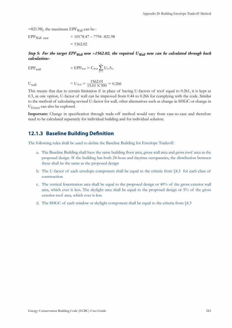
Appendix D: Building Envelope Tradeoff Method
Energy Conservation Building Code (ECBC) User Guide D.5
=821.98), the maximum EPFWall can be :
EPFWall new = 10178.47 – 7794 -821.98
= 1562.02
For the target EPFStep 5: Wall new =1562.02, the required UWall new can be calculated through back calculation:-
EPFwall = EPF C U A1
Wall Wall S SS
n
==
/
Uwall = .. 0.266U 15 01 390
1562 01Wall #
= =
This means that due to certain limitation if in place of having U-factors of roof equal to 0.261, it is kept as 0.3, as one option, U-factor of wall can be improved from 0.44 to 0.266 for complying with the code. Similar to the method of calculating revised U-factor for wall, other alternatives such as change in SHGC or change in UFenest can also be explored.
Important: Change in specification through trade-off method would vary from case-to-case and therefore need to be calculated separately for individual building and for individual solution.
Baseline Building Definition12.1.3
The following rules shall be used to define the Baseline Building for Envelope Tradeoff:
The Baseline Building shall have the same building floor area, gross wall area and gross roof area as the a. proposed design. If the building has both 24-hour and daytime occupancies, the distribution between these shall be the same as the proposed design
The U-factor of each envelope component shall be equal to the criteria from §4.3 for each class of b. construction
The vertical fenestration area shall be equal to the proposed design or 40% of the gross exterior wall c. area, which ever is less. The skylight area shall be equal to the proposed design or 5% of the gross exterior roof area, which ever is less
The SHGC of each window or skylight component shall be equal to the criteria from §4.3 d.
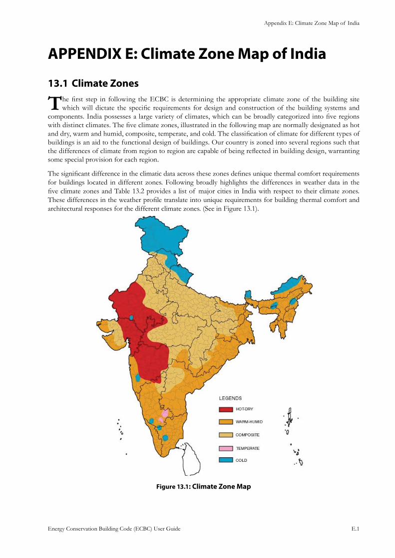
Appendix E: Climate Zone Map of India
Energy Conservation Building Code (ECBC) User Guide E.1
APPENDIX E: Climate Zone Map of India
Climate Zones13.1
The first step in following the ECBC is determining the appropriate climate zone of the building site which will dictate the specific requirements for design and construction of the building systems and
components. India possesses a large variety of climates, which can be broadly categorized into five regions with distinct climates. The five climate zones, illustrated in the following map are normally designated as hot and dry, warm and humid, composite, temperate, and cold. The classification of climate for different types of buildings is an aid to the functional design of buildings. Our country is zoned into several regions such that the differences of climate from region to region are capable of being reflected in building design, warranting some special provision for each region.
The significant difference in the climatic data across these zones defines unique thermal comfort requirements for buildings located in different zones. Following broadly highlights the differences in weather data in the five climate zones and Table 13.2 provides a list of major cities in India with respect to their climate zones. These differences in the weather profile translate into unique requirements for building thermal comfort and architectural responses for the different climate zones. (See in Figure 13.1).
: Climate Zone MapFigure 13.1
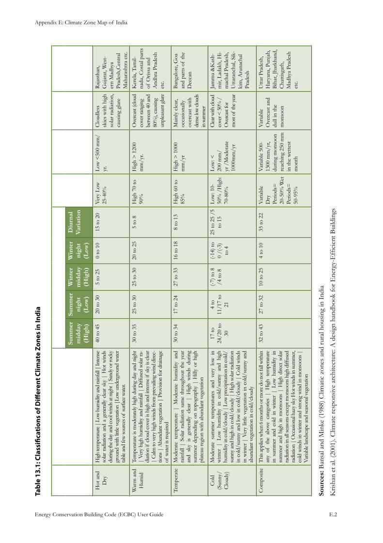
Appendix E: Climate Zone Map of India
Energy Conservation Building Code (ECBC) User Guide E.2
: Ta
ble
13.1
Clas
sific
atio
ns o
f Diff
eren
t Clim
ate
Zone
s in
Indi
a
Clim
ate
Zon
eD
escr
ipti
onM
ean
Tem
pera
ture
(°C
)M
ean
Rel
ativ
e hu
mid
ity
Ann
ual
Pre
cipi
tati
on
Sky
Con
diti
ons
Pla
ces
Sum
mer
m
idda
y (H
igh)
Sum
mer
ni
ght
(Low
)
Win
ter
mid
day
(Hig
h)
Win
ter
nigh
t (L
ow)
Diu
rnal
Va
riat
ion
Hot
and
D
ry
Hig
h te
mpe
ratu
re |
Low
hum
idity
and
rain
fall |
Inte
nse
solar
rad
iatio
n an
d a
gene
rally
clea
r sk
y |
Hot
win
ds
durin
g th
e day
and
cool
win
ds at
nig
ht |
San
dy o
r roc
ky
grou
nd w
ith li
ttle
vege
tatio
n |L
ow u
nder
grou
nd w
ater
ta
ble a
nd fe
w so
urce
s of
surfa
ce w
ater
.
40 to
45
20 to
30
5 to
25
0 to
10
15 to
20
Ver
y Lo
w
25-4
0%Lo
w <
500
mm
/yr
.C
loud
less
sk
ies
with
hig
h so
lar r
adia
tion,
ca
usin
g gl
are
Raj
asth
an,
Guj
arat
, Wes
t-er
n M
adhy
a Pr
ades
h,C
entr
al
Mah
aras
htra
etc
.
War
m a
nd
Hum
idTe
mpe
ratu
re is
mod
erat
ely h
igh
durin
g da
y an
d ni
ght
| Ve
ry h
igh
hum
idity
and
rain
fall
| D
iffus
ed so
lar ra
-di
atio
n if
clo
ud c
over
is h
igh
and
inte
nse
if sk
y is
clear
|
Calm
to v
ery h
igh
win
ds fr
om p
reva
iling
win
d di
rec-
tions
| A
bund
ant v
eget
atio
n |
Prov
ision
for d
rain
age
of w
ater
is re
quire
d
30 to
35
25 to
30
25 to
30
20 to
25
5 to
8H
igh
70 to
90
%H
igh
> 1
200
mm
/yr.
Ove
rcas
t (clo
ud
cove
r ran
ging
be
twee
n 40
and
80
%),
caus
ing
unpl
easa
nt g
lare
Ker
ela,
Tam
il-na
du, C
osta
l par
ts
of O
rissa
and
A
ndhr
a Pr
ades
h et
c.
Tem
pera
te
Mod
erat
e te
mpe
ratu
re |
Mod
erat
e hu
mid
ity a
nd
rain
fall
| So
lar
radi
atio
n sa
me
thro
ugho
ut t
he y
ear
and
sky
is ge
nera
lly c
lear
| H
igh
win
ds d
urin
g su
mm
er d
epen
ding
on
topo
grap
hy |
Hill
y or
hig
h pl
atea
u re
gion
with
abu
ndan
t veg
etat
ion
30 to
34
17 to
24
27 to
33
16 to
18
8 to
13
Hig
h 60
to
85%
Hig
h >
100
0 m
m/y
rM
ainl
y cl
ear,
occa
sion
ally
ov
erca
st w
ith
dens
e low
clou
ds
in su
mm
er
Ban
galo
re, G
oa
and
part
s of
the
Dec
can
Col
d (S
unny
/C
loud
y)
Mod
erat
e su
mm
er t
empe
ratu
res
and
very
low
in
win
ter
| Lo
w h
umid
ity i
n co
ld/s
unny
and
hig
h hu
mid
ity in
cold
/clo
udy |
Low
pre
cipi
tatio
n in
cold
/su
nny
and
high
in c
old/
clou
dy |
Hig
h so
lar r
adia
tion
in c
old/
sunn
y an
d lo
w in
col
d/cl
oudy
| C
old
win
ds
in w
inte
r |
Very
littl
e ve
geta
tion
in c
old/
sunn
y an
d ab
unda
nt v
eget
atio
n in
col
d/cl
oudy
17 to
24
/20
to
30
4 to
11
/17
to
21
(-7)
to 8
/4
to 8
(-14
) to
0 /(
-3)
to 4
25 to
25
/5
to 1
5Lo
w: 1
0-50
% /
Hig
h:
70-8
0%
Low
: <
200
mm
/yr
/M
oder
ate
1000
mm
/yr
Clea
r with
clou
d co
ver <
50%
/O
verc
ast f
or
mos
t of
the y
ear
Jam
mu
&K
ash-
mir,
Lad
akh,
Hi-
mac
hal P
rade
sh,
Utta
ranc
hal,
Sik-
kim
, Aru
nach
al
Prad
esh
Com
posi
te
Thi
s app
lies w
hen
6 m
onth
s or m
ore d
o no
t fall
with
in
any
of t
he a
bove
cat
egor
ies |
Hig
h te
mpe
ratu
re
in s
umm
er a
nd c
old
in w
inte
r |
Low
hum
idity
in
sum
mer
and
hig
h in
mon
soon
s |
Hig
h di
rect
sol
ar
radi
atio
n in
all s
easo
ns ex
cept
mon
soon
s hig
h di
ffuse
d ra
diat
ion
| O
ccas
iona
l haz
y sky
Hot
win
ds in
sum
mer
, co
ld w
inds
in w
inte
r and
stro
ng w
ind
in m
onso
ons
| Va
riabl
e lan
dsca
pe a
nd se
ason
al ve
geta
tion
32 to
43
27 to
32
10 to
25
4 to
10
35 to
22
Var
iabl
e D
ry
Perio
ds=
20
-50%
Wet
Pe
riods
=
50-9
5%
Var
iabl
e 50
0-13
00 m
m/y
r, du
ring
mon
soon
re
achi
ng 2
50 m
m
in th
e w
ette
st
mon
th
Var
iabl
e O
verc
ast a
nd
dull
in th
e m
onso
on
Utta
r Pra
desh
, H
arya
na, P
unja
b,
Bih
ar, J
hark
hand
, C
hatti
sgar
h,
Mad
hya
Prad
esh
etc.
Sour
ces:
Ban
sal a
nd M
inke
(198
8) C
limat
ic z
ones
and
rur
al h
ousi
ng in
Ind
ia
Kris
han
et a
l. (2
001)
. Clim
ate
resp
onsiv
e ar
chite
ctur
e: A
des
ign
hand
book
for E
nerg
y-E
ffici
ent B
uild
ings
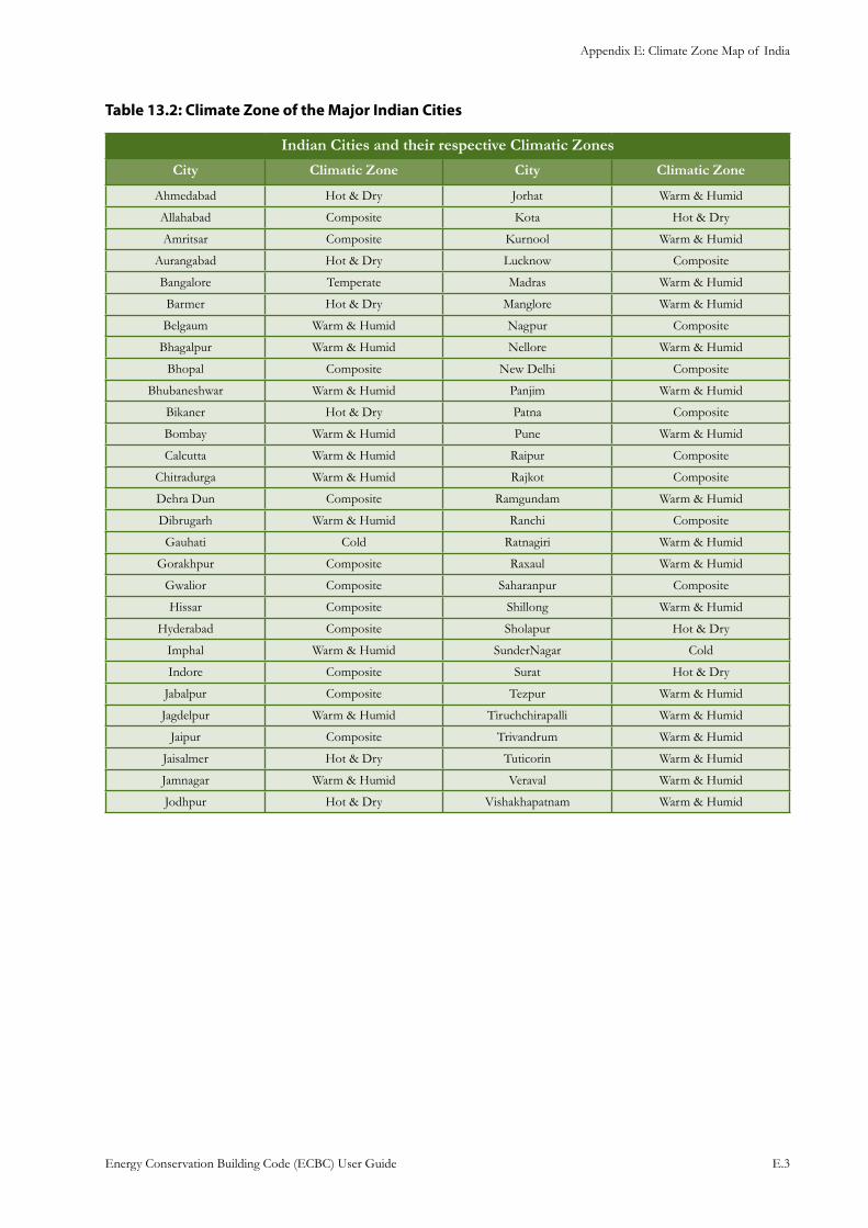
Appendix E: Climate Zone Map of India
Energy Conservation Building Code (ECBC) User Guide E.3
Table 13.2: Climate Zone of the Major Indian Cities
Indian Cities and their respective Climatic Zones
City Climatic Zone City Climatic Zone
Ahmedabad Hot & Dry Jorhat Warm & Humid
Allahabad Composite Kota Hot & Dry
Amritsar Composite Kurnool Warm & Humid
Aurangabad Hot & Dry Lucknow Composite
Bangalore Temperate Madras Warm & Humid
Barmer Hot & Dry Manglore Warm & Humid
Belgaum Warm & Humid Nagpur Composite
Bhagalpur Warm & Humid Nellore Warm & Humid
Bhopal Composite New Delhi Composite
Bhubaneshwar Warm & Humid Panjim Warm & Humid
Bikaner Hot & Dry Patna Composite
Bombay Warm & Humid Pune Warm & Humid
Calcutta Warm & Humid Raipur Composite
Chitradurga Warm & Humid Rajkot Composite
Dehra Dun Composite Ramgundam Warm & Humid
Dibrugarh Warm & Humid Ranchi Composite
Gauhati Cold Ratnagiri Warm & Humid
Gorakhpur Composite Raxaul Warm & Humid
Gwalior Composite Saharanpur Composite
Hissar Composite Shillong Warm & Humid
Hyderabad Composite Sholapur Hot & Dry
Imphal Warm & Humid SunderNagar Cold
Indore Composite Surat Hot & Dry
Jabalpur Composite Tezpur Warm & Humid
Jagdelpur Warm & Humid Tiruchchirapalli Warm & Humid
Jaipur Composite Trivandrum Warm & Humid
Jaisalmer Hot & Dry Tuticorin Warm & Humid
Jamnagar Warm & Humid Veraval Warm & Humid
Jodhpur Hot & Dry Vishakhapatnam Warm & Humid
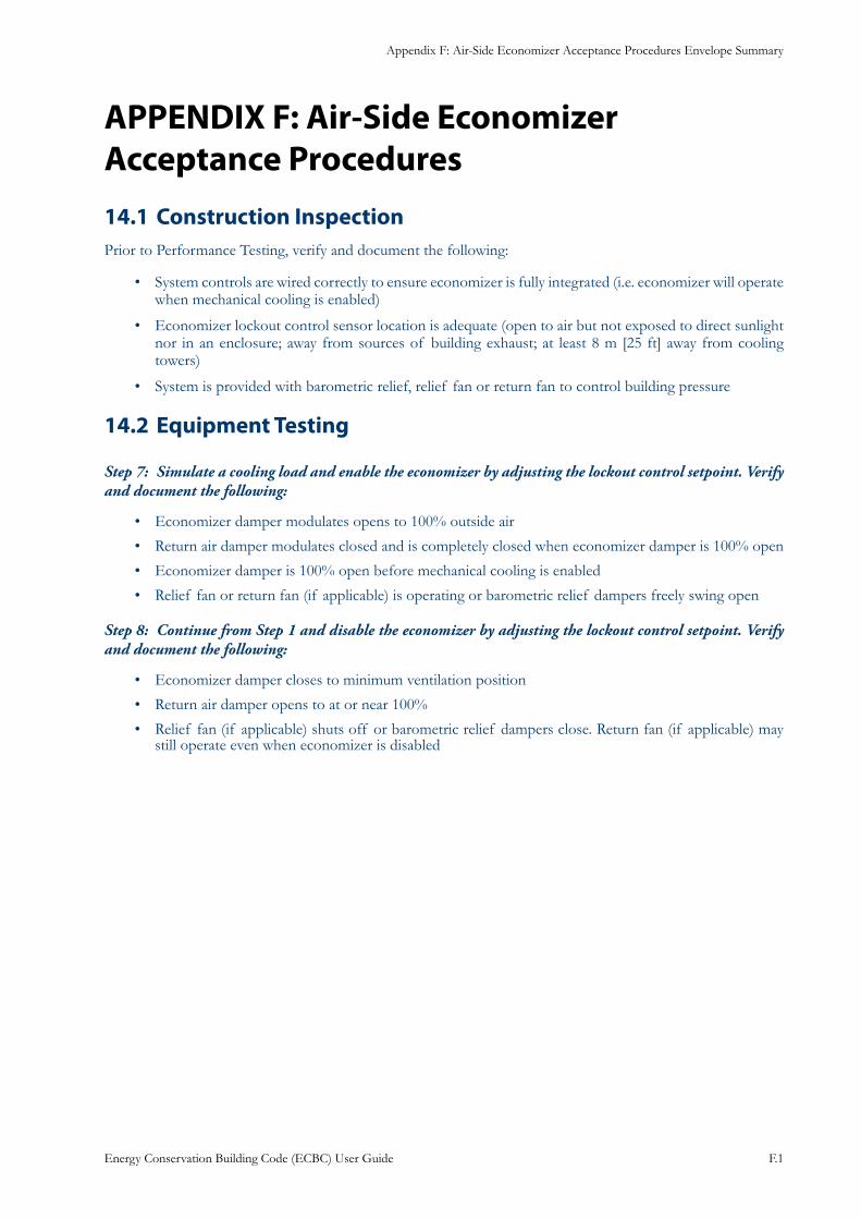
Appendix F: Air-Side Economizer Acceptance Procedures Envelope Summary
Energy Conservation Building Code (ECBC) User Guide F.1
APPENDIX F: Air-Side Economizer Acceptance Procedures
Construction Inspection14.1 Prior to Performance Testing, verify and document the following:
System controls are wired correctly to ensure economizer is fully integrated (i.e. economizer will operate • when mechanical cooling is enabled)
Economizer lockout control sensor location is adequate (open to air but not exposed to direct sunlight • nor in an enclosure; away from sources of building exhaust; at least 8 m [25 ft] away from cooling towers)
System is provided with barometric relief, relief fan or return fan to control building pressure•
Equipment Testing14.2
Simulate a cooling load and enable the economizer by adjusting the lockout control setpoint. Verify Step 7: and document the following:
Economizer damper modulates opens to 100% outside air•
Return air damper modulates closed and is completely closed when economizer damper is 100% open•
Economizer damper is 100% open before mechanical cooling is enabled•
Relief fan or return fan (if applicable) is operating or barometric relief dampers freely swing open•
Continue from Step 1 and disable the economizer by adjusting the lockout control setpoint. Verify Step 8: and document the following:
Economizer damper closes to minimum ventilation position•
Return air damper opens to at or near 100%•
Relief fan (if applicable) shuts off or barometric relief dampers close. Return fan (if applicable) may • still operate even when economizer is disabled
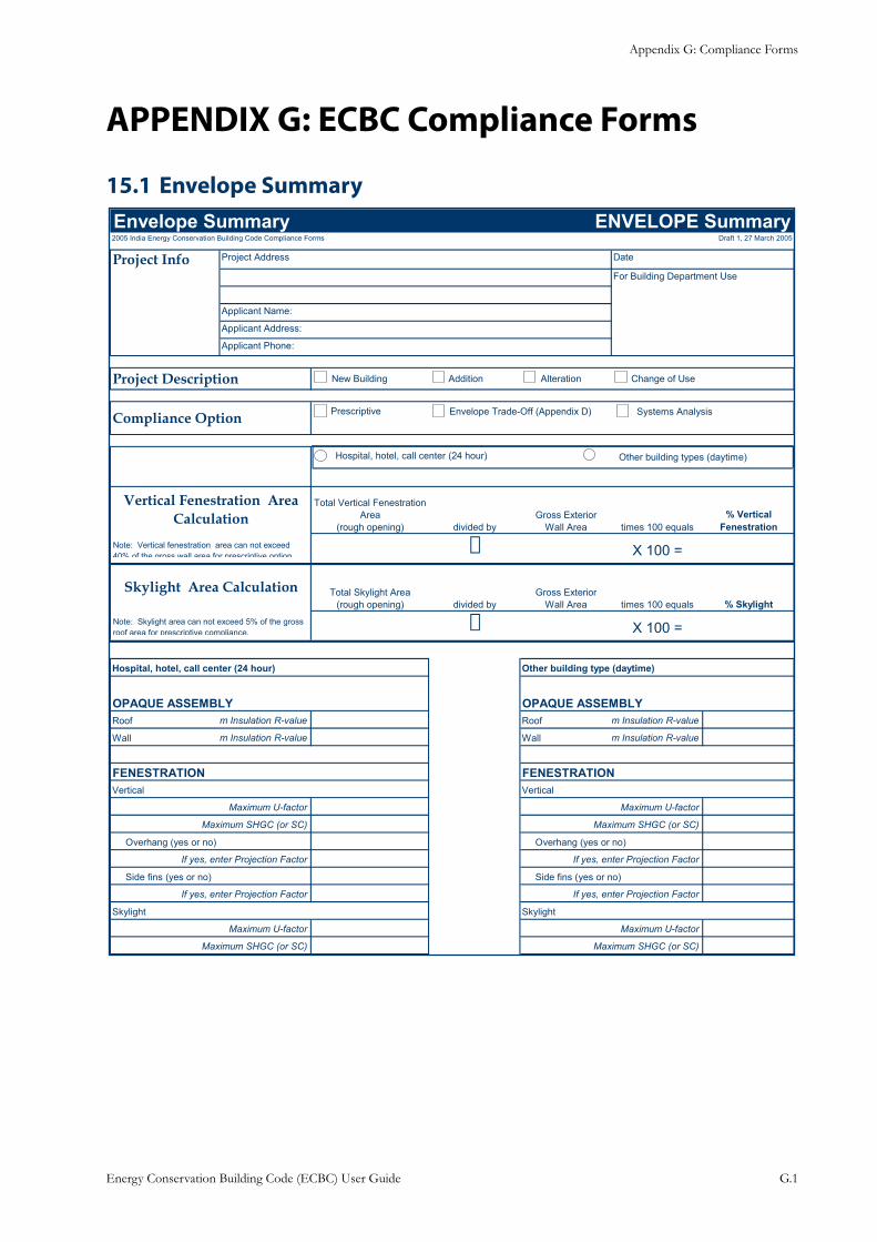
Appendix G: Compliance Forms
Energy Conservation Building Code (ECBC) User Guide G.1
APPENDIX G: ECBC Compliance Forms
Envelope Summary15.1 Envelope Summary ENVELOPE Summary2005 India Energy Conservation Building Code Compliance Forms Draft 1, 27 March 2005
Project Info Project Address Date
For Building Department Use
Applicant Name:
Applicant Address:
Applicant Phone:
Project Description
Compliance Option
Total Vertical Fenestration Area
(rough opening) divided byGross Exterior
Wall Area times 100 equals% Vertical
Fenestration
X 100 =
Total Skylight Area(rough opening) divided by
Gross ExteriorWall Area times 100 equals % Skylight
X 100 =
Hospital, hotel, call center (24 hour) Other building type (daytime)
OPAQUE ASSEMBLY OPAQUE ASSEMBLYRoof m Insulation R-value Roof m Insulation R-value
Wall m Insulation R-value Wall m Insulation R-value
FENESTRATION FENESTRATIONVertical Vertical
Maximum U-factor Maximum U-factor
Maximum SHGC (or SC) Maximum SHGC (or SC)
Overhang (yes or no) Overhang (yes or no)
If yes, enter Projection Factor If yes, enter Projection Factor
Side fins (yes or no) Side fins (yes or no)
If yes, enter Projection Factor If yes, enter Projection Factor
Skylight Skylight
Maximum U-factor Maximum U-factor
Maximum SHGC (or SC) Maximum SHGC (or SC)
Vertical Fenestration Area Calculation
Skylight Area Calculation
Note: Vertical fenestration area can not exceed 40% of the gross wall area for prescriptive option
New Building Addition Alteration Change of Use
Prescriptive Envelope Trade-Off (Appendix D) Systems Analysis
Hospital, hotel, call center (24 hour) Other building types (daytime)
Note: Skylight area can not exceed 5% of the gross roof area for prescriptive compliance.
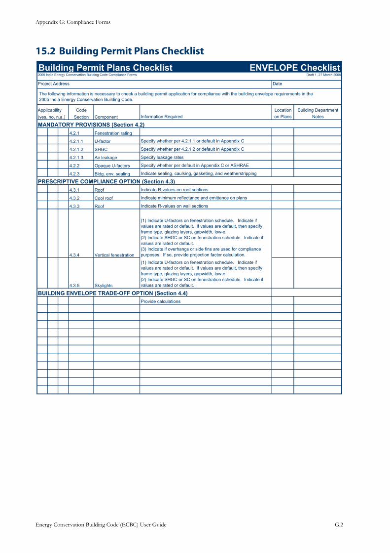
Appendix G: Compliance Forms
Energy Conservation Building Code (ECBC) User Guide G.2
Building Permit Plans Checklist15.2
Building Permit Plans Checklist ENVELOPE Checklist2005 India Energy Conservation Building Code Compliance Forms Draft 1, 27 March 2005
Project Address Date
Applicability Code Location Building Department(yes, no, n.a.) Section Component Information Required on Plans Notes
MANDATORY PROVISIONS (Section 4.2)4.2.1 Fenestration rating
4.2.1.1 U-factor Specify whether per 4.2.1.1 or default in Appendix C
4.2.1.2 SHGC Specify whether per 4.2.1.2 or default in Appendix C
4.2.1.3 Air leakage Specify leakage rates
4.2.2 Opaque U-factors Specify whether per default in Appendix C or ASHRAE
4.2.3 Bldg. env. sealing Indicate sealing, caulking, gasketing, and weatherstripping
PRESCRIPTIVE COMPLIANCE OPTION (Section 4.3)4.3.1 Roof Indicate R-values on roof sections
4.3.2 Cool roof Indicate minimum reflectance and emittance on plans
4.3.3 Roof Indicate R-values on wall sections
4.3.4 Vertical fenestration
(1) Indicate U-factors on fenestration schedule. Indicate if values are rated or default. If values are default, then specify frame type, glazing layers, gapwidth, low-e.(2) Indicate SHGC or SC on fenestration schedule. Indicate if values are rated or default.(3) Indicate if overhangs or side fins are used for compliance purposes. If so, provide projection factor calculation.
4.3.5 Skylights
(1) Indicate U-factors on fenestration schedule. Indicate if values are rated or default. If values are default, then specify frame type, glazing layers, gapwidth, low-e.(2) Indicate SHGC or SC on fenestration schedule. Indicate if values are rated or default.
BUILDING ENVELOPE TRADE-OFF OPTION (Section 4.4)Provide calculations
The following information is necessary to check a building permit application for compliance with the building envelope requirements in the 2005 India Energy Conservation Building Code.
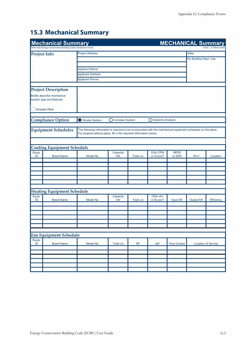
Appendix G: Compliance Forms
Energy Conservation Building Code (ECBC) User Guide G.3
Mechanical Summary15.3
Mechanical Summary MECHANICAL Summary2005 India Energy Conservation Building Code Compliance Forms Draft 1, 27 March 2005
Project Info Project Address
For Building Dept. Use
Applicant Name:
Applicant Address: 0
Applicant Phone: 0
Project DescriptionBriefly describe mechanicalsystem type and features.
FALSE
Compliance Option
Equipment Schedules
Cooling Equipment ScheduleEquip.
ID Brand Name Model No.Capacity
kW Total L/sOSA CFMor Econo?
SEERor EER IPLV Location
Heating Equipment ScheduleEquip.
ID Brand Name Model No.Capacity
kW Total L/sOSA cfmor Econo? Input kW Output kW Efficiency
Fan Equipment ScheduleEquip.
ID Brand Name Model No. Total L/s SP kW Flow Control Location of Service
The following information is required to be incorporated with the mechanical equipment schedules on the plans. For projects without plans, fill in the required information below.
Simple System Complex System Systems Analysis
Includes Plans
Date
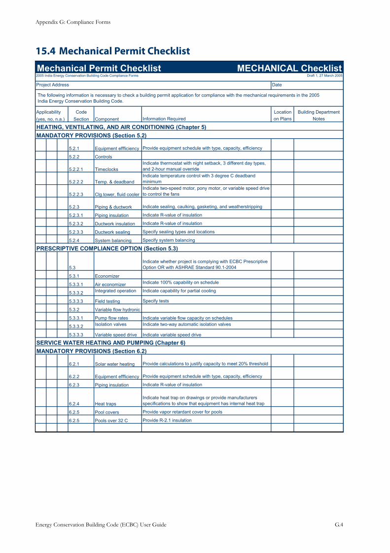
Appendix G: Compliance Forms
Energy Conservation Building Code (ECBC) User Guide G.4
Mechanical Permit Checklist15.4
Mechanical Permit Checklist MECHANICAL Checklist2005 India Energy Conservation Building Code Compliance Forms Draft 1, 27 March 2005
Project Address Date
Applicability Code Location Building Department(yes, no, n.a.) Section Component Information Required on Plans Notes
HEATING, VENTILATING, AND AIR CONDITIONING (Chapter 5)MANDATORY PROVISIONS (Section 5.2)
5.2.1 Equipment effficiency Provide equipment schedule with type, capacity, efficiency
5.2.2 Controls
5.2.2.1 TimeclocksIndicate thermostat with night setback, 3 different day types, and 2-hour manual override
5.2.2.2 Temp. & deadbandIndicate temperature control with 3 degree C deadband minimum
5.2.2.3 Clg.tower, fluid coolerIndicate two-speed motor, pony motor, or variable speed drive to control the fans
5.2.3 Piping & ductwork Indicate sealing, caulking, gasketing, and weatherstripping
5.2.3.1 Piping insulation Indicate R-value of insulation
5.2.3.2 Ductwork insulation Indicate R-value of insulation
5.2.3.3 Ductwork sealing Specify sealing types and locations
5.2.4 System balancing Specify system balancing
PRESCRIPTIVE COMPLIANCE OPTION (Section 5.3)
5.3Indicate whether project is complying with ECBC Prescriptive Option OR with ASHRAE Standard 90.1-2004
5.3.1 Economizer
5.3.3.1 Air economizer Indicate 100% capability on schedule
5.3.3.2 Integrated operation Indicate capability for partial cooling
5.3.3.3 Field testing Specify tests
5.3.2 Variable flow hydronic
5.3.3.1 Pump flow rates Indicate variable flow capacity on schedules
5.3.3.2 Isolation valves Indicate two-way automatic isolation valves
5.3.3.3 Variable speed drive Indicate variable speed drive
SERVICE WATER HEATING AND PUMPING (Chapter 6)MANDATORY PROVISIONS (Section 6.2)
6.2.1 Solar water heating Provide calculations to justify capacity to meet 20% threshold
6.2.2 Equipment effficiency Provide equipment schedule with type, capacity, efficiency
6.2.3 Piping insulation Indicate R-value of insulation
6.2.4 Heat trapsIndicate heat trap on drawings or provide manufacturers specifications to show that equipment has internal heat trap
6.2.5 Pool covers Provide vapor retardant cover for pools
6.2.5 Pools over 32 C Provide R-2.1 insulation
The following information is necessary to check a building permit application for compliance with the mechanical requirements in the 2005 India Energy Conservation Building Code.
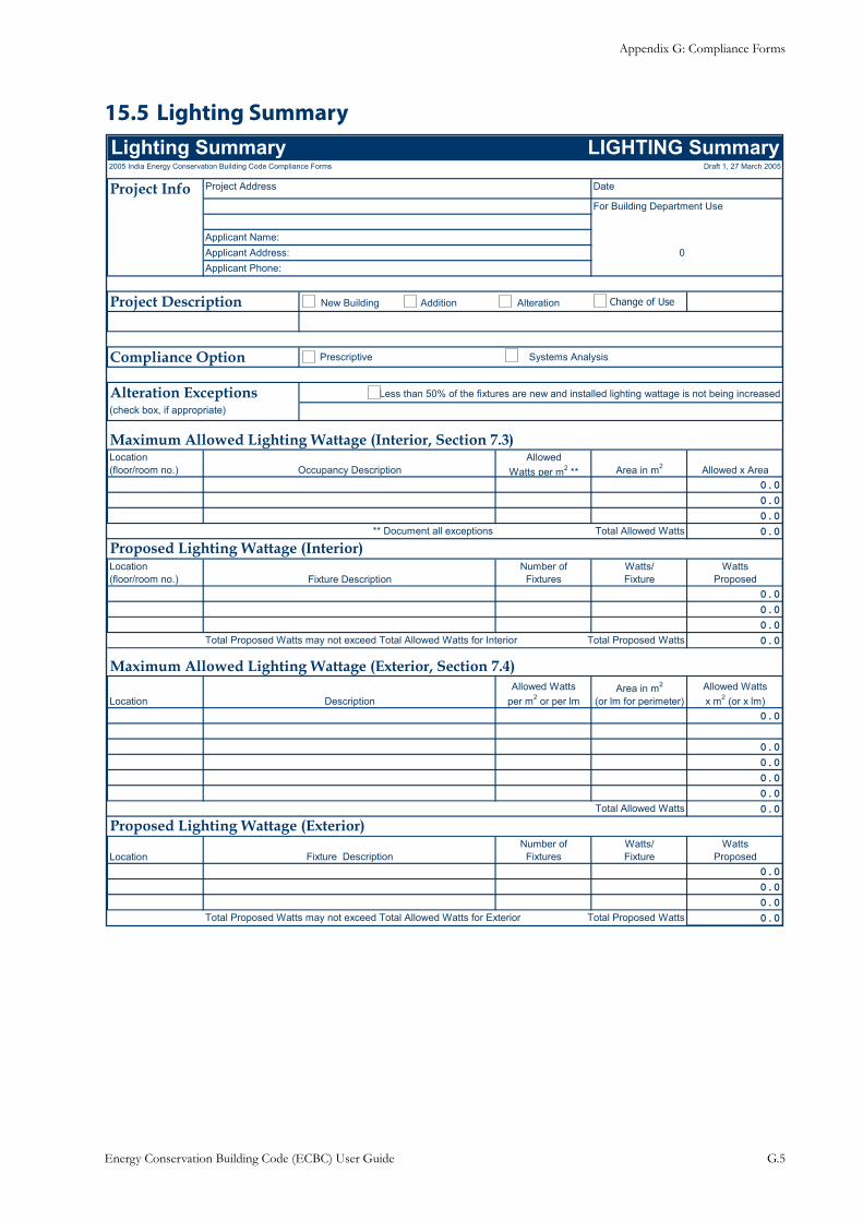
Appendix G: Compliance Forms
Energy Conservation Building Code (ECBC) User Guide G.5
Lighting Summary15.5 Lighting Summary LIGHTING Summary2005 India Energy Conservation Building Code Compliance Forms Draft 1, 27 March 2005
Project Info Project Address Date
For Building Department Use
Applicant Name:Applicant Address: 0Applicant Phone:
Project Description
Compliance Option
Alteration Exceptions Less than 50% of the fixtures are new and installed lighting wattage is not being increased(check box, if appropriate)
Maximum Allowed Lighting Wattage (Interior, Section 7.3)Location(floor/room no.) Occupancy Description
AllowedWatts per m2 ** Area in m2 Allowed x Area
0.00.00.0
** Document all exceptions Total Allowed Watts 0.0
Proposed Lighting Wattage (Interior)Location(floor/room no.) Fixture Description
Number of Fixtures
Watts/Fixture
Watts Proposed
0.00.00.0
Total Proposed Watts may not exceed Total Allowed Watts for Interior Total Proposed Watts 0.0
Maximum Allowed Lighting Wattage (Exterior, Section 7.4)
Location DescriptionAllowed Watts
per m2 or per lmArea in m2
(or lm for perimeter)Allowed Watts x m2 (or x lm)
0.0
0.00.00.00.0
Total Allowed Watts 0.0
Proposed Lighting Wattage (Exterior)
Location Fixture DescriptionNumber of
FixturesWatts/Fixture
Watts Proposed
0.00.00.0
Total Proposed Watts may not exceed Total Allowed Watts for Exterior Total Proposed Watts 0.0
Change of UseNew Building Addition Alteration
Prescriptive Systems Analysis
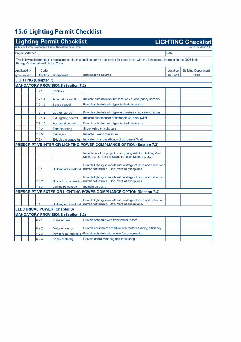
Lighting Permit Checklist15.6 Lighting Permit Checklist LIGHTING Checklist2005 India Energy Conservation Building Code Compliance Forms Draft 1, 27 March 2005
Project Address Date
Applicability Code Location Building Department(yes, no, n.a.) Section Component Information Required on Plans Notes
LIGHTING (Chapter 7)MANDATORY PROVISIONS (Section 7.2)
7.2.1 Controls
7.2.1.1 Automatic shutoff Indicate automatic shutoff locations or occupancy sensors
7.2.1.2 Space control Provide schedule with type, indicate locations
7.2.1.3 Daylight zones Provide schedule with type and features, indicate locations
7.2.1.4 Ext. lighting control Indicate photosensor or astronomical time switch
7.2.1.5 Additional control Provide schedule with type, indicate locations
7.2.2 Tandem wiring Show wiring on schedule
7.2.3 Exit signs Indicate 5 watts maximum
7.2.4 Ext. bldg.grounds ltg. Indicate minimum efficacy of 60 lumens/Watt
PRESCRIPTIVE INTERIOR LIGHTING POWER COMPLIANCE OPTION (Section 7.3)
7.3Indicate whether project is complying with the Building Area Method (7.3.1) or the Space Function Method (7.3.2)
7.3.1 Building area methodProvide lighting schedule with wattage of lamp and ballast and number of fixtures. Document all exceptions.
7.3.2 Space function methodProvide lighting schedule with wattage of lamp and ballast and number of fixtures. Document all exceptions.
7.3.3 Luminaire wattage Indicate on plans
PRESCRIPTIVE EXTERIOR LIGHTING POWER COMPLIANCE OPTION (Section 7.4)
7.4 Building area methodProvide lighting schedule with wattage of lamp and ballast and number of fixtures. Document all exceptions.
ELECTRICAL POWER (Chapter 8)MANDATORY PROVISIONS (Section 8.2)
8.2.1 Transformers Provide schedule with transformer losses
8.2.2 Motor efficiency Provide equipment schedule with motor capacity, efficiency
8.2.3 Power factor correctionProvide schedule with power factor correction
8.2.4 Check metering Provide check metering and monitoring
The following information is necessary to check a building permit application for compliance with the lighting requirements in the 2005 India Energy Conservation Building Code.
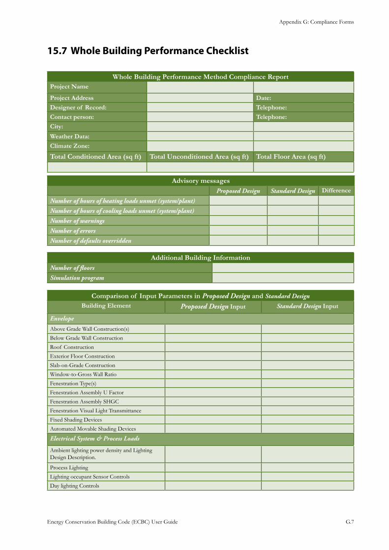
Appendix G: Compliance Forms
Energy Conservation Building Code (ECBC) User Guide G.7
Whole Building Performance Checklist15.7
Whole Building Performance Method Compliance ReportProject Name
Project Address Date: Designer of Record: Telephone: Contact person: Telephone:
City:
Weather Data:
Climate Zone:
Total Conditioned Area (sq ft) Total Unconditioned Area (sq ft) Total Floor Area (sq ft)
Advisory messagesProposed Design Standard Design Difference
Number of hours of heating loads unmet (system/plant)
Number of hours of cooling loads unmet (system/plant)
Number of warnings
Number of errors
Number of defaults overridden
Additional Building InformationNumber of floors
Simulation program
Comparison of Input Parameters in Proposed Design and Standard DesignBuilding Element Proposed Design Input Standard Design Input
Envelope
Above Grade Wall Construction(s)
Below Grade Wall Construction
Roof Construction
Exterior Floor Construction
Slab-on-Grade Construction
Window-to-Gross Wall Ratio
Fenestration Type(s)
Fenestration Assembly U Factor
Fenestration Assembly SHGC
Fenestration Visual Light Transmittance
Fixed Shading Devices
Automated Movable Shading Devices
Electrical System & Process Loads
Ambient lighting power density and Lighting Design Description.
Process Lighting
Lighting occupant Sensor Controls
Day lighting Controls
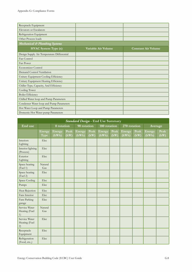
Appendix G: Compliance Forms
Energy Conservation Building Code (ECBC) User Guide G.8
Receptacle Equipment
Elevators or Escalators
Refrigeration Equipment
Other Process loads
Mechanical & Plumbing Systems
HVAC System Type (s) Variable Air Volume Constant Air Volume
Design Supply Air Temperature Differential
Fan Control
Fan Power
Economizer Control
Demand Control Ventilation
Unitary Equipment Cooling Efficiency
Unitary Equipment Heating Efficiency
Chiller Type, Capacity, And Efficiency
Cooling Tower
Boiler Efficiency
Chilled Water loop and Pump Parameters
Condenser Water loop and Pump Parameters
Hot Water Loop and Pump Parameters
Domestic Hot Water pump Parameters
Standard Design - End Use SummaryEnd use 0 rotation 90 rotation 180 rotation 270 rotation Average
Energy Type
Energy (kWh)
Peak (kW)
Energy (kWh)
Peak (kW)
Energy (kWh)
Peak (kW)
Energy (kWh)
Peak (kW)
Energy (kWh)
Peak (kW)
Interiors Lighting
Elec
Interior lighting (Process)
Elec
Exterior Lighting
Elec
Space heating (Fuel 1)
Natural Gas
Space heating (Fuel 2)
Elec
Space Cooling Elec
Pumps Elec
Heat Rejection Elec
Fans Interior Elec
Fans Parking garage
Elec
Service Water Heating (Fuel 1)
Natural Gas
Service Water Heating (Fuel 2)
Elec
Receptacle Equipment
Elec
Refrigeration (Food, etc.,)
Elec
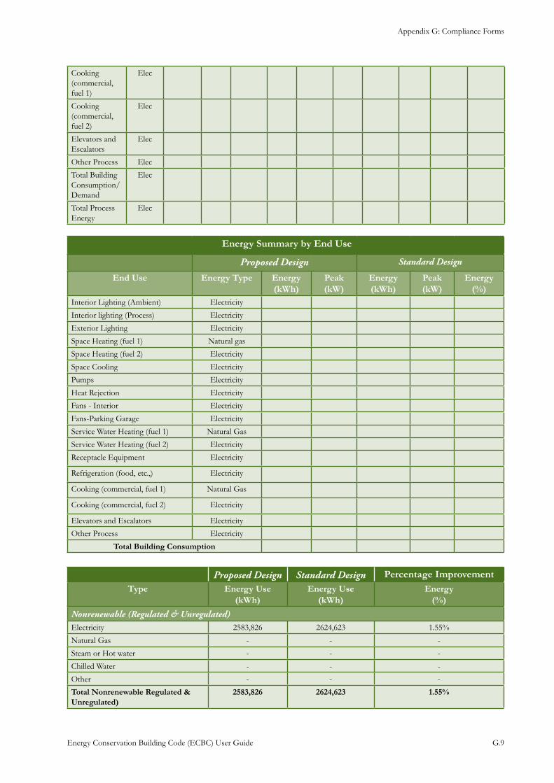
Appendix G: Compliance Forms
Energy Conservation Building Code (ECBC) User Guide G.9
Cooking (commercial, fuel 1)
Elec
Cooking (commercial, fuel 2)
Elec
Elevators and Escalators
Elec
Other Process Elec
Total Building Consumption/Demand
Elec
Total Process Energy
Elec
Energy Summary by End Use
Proposed Design Standard Design
End Use Energy Type Energy (kWh)
Peak (kW)
Energy (kWh)
Peak (kW)
Energy (%)
Interior Lighting (Ambient) Electricity
Interior lighting (Process) Electricity
Exterior Lighting Electricity
Space Heating (fuel 1) Natural gas
Space Heating (fuel 2) Electricity
Space Cooling Electricity
Pumps Electricity
Heat Rejection Electricity
Fans - Interior Electricity
Fans-Parking Garage Electricity
Service Water Heating (fuel 1) Natural Gas
Service Water Heating (fuel 2) Electricity
Receptacle Equipment Electricity
Refrigeration (food, etc.,) Electricity
Cooking (commercial, fuel 1) Natural Gas
Cooking (commercial, fuel 2) Electricity
Elevators and Escalators Electricity
Other Process Electricity
Total Building Consumption
Proposed Design Standard Design Percentage ImprovementType Energy Use
(kWh)Energy Use
(kWh)Energy
(%)
Nonrenewable (Regulated & Unregulated)Electricity 2583,826 2624,623 1.55%
Natural Gas - - -
Steam or Hot water - - -
Chilled Water - - -
Other - - -
Total Nonrenewable Regulated & Unregulated)
2583,826 2624,623 1.55%
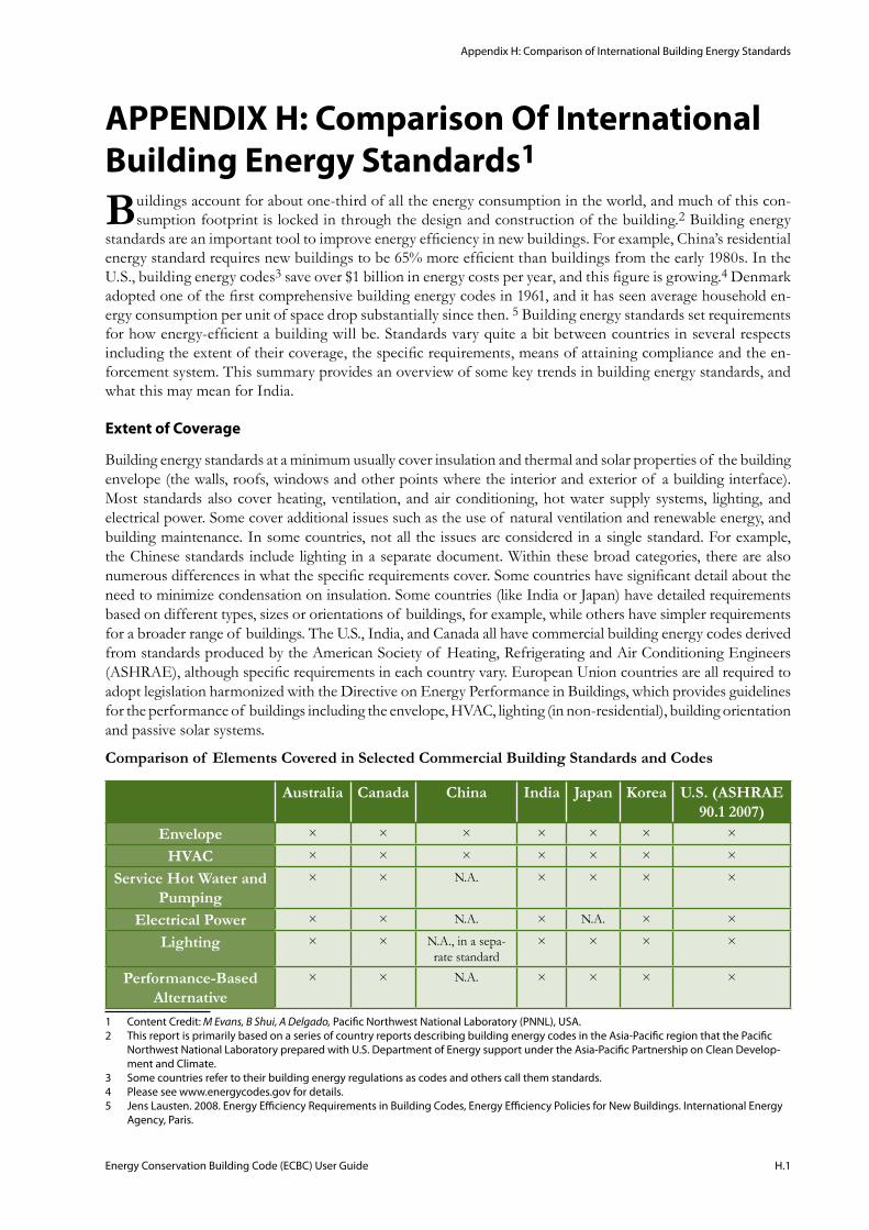
Appendix H: Comparison of International Building Energy Standards
Energy Conservation Building Code (ECBC) User Guide H.1
APPENDIX H: Comparison Of International Building Energy Standards1
Buildings account for about one-third of all the energy consumption in the world, and much of this con-sumption footprint is locked in through the design and construction of the building.2 Building energy
standards are an important tool to improve energy efficiency in new buildings. For example, China’s residential energy standard requires new buildings to be 65% more efficient than buildings from the early 1980s. In the U.S., building energy codes3 save over $1 billion in energy costs per year, and this figure is growing.4 Denmark adopted one of the first comprehensive building energy codes in 1961, and it has seen average household en-ergy consumption per unit of space drop substantially since then. 5 Building energy standards set requirements for how energy-efficient a building will be. Standards vary quite a bit between countries in several respects including the extent of their coverage, the specific requirements, means of attaining compliance and the en-forcement system. This summary provides an overview of some key trends in building energy standards, and what this may mean for India.
Extent of Coverage
Building energy standards at a minimum usually cover insulation and thermal and solar properties of the building envelope (the walls, roofs, windows and other points where the interior and exterior of a building interface). Most standards also cover heating, ventilation, and air conditioning, hot water supply systems, lighting, and electrical power. Some cover additional issues such as the use of natural ventilation and renewable energy, and building maintenance. In some countries, not all the issues are considered in a single standard. For example, the Chinese standards include lighting in a separate document. Within these broad categories, there are also numerous differences in what the specific requirements cover. Some countries have significant detail about the need to minimize condensation on insulation. Some countries (like India or Japan) have detailed requirements based on different types, sizes or orientations of buildings, for example, while others have simpler requirements for a broader range of buildings. The U.S., India, and Canada all have commercial building energy codes derived from standards produced by the American Society of Heating, Refrigerating and Air Conditioning Engineers (ASHRAE), although specific requirements in each country vary. European Union countries are all required to adopt legislation harmonized with the Directive on Energy Performance in Buildings, which provides guidelines for the performance of buildings including the envelope, HVAC, lighting (in non-residential), building orientation and passive solar systems.
Comparison of Elements Covered in Selected Commercial Building Standards and Codes
Australia Canada China India Japan Korea U.S. (ASHRAE 90.1 2007)
Envelope × × × × × × ×
HVAC × × × × × × ×
Service Hot Water and Pumping
× × N.A. × × × ×
Electrical Power × × N.A. × N.A. × ×
Lighting × × N.A., in a sepa-rate standard
× × × ×
Performance-Based Alternative
× × N.A. × × × ×
1 Content Credit: M Evans, B Shui, A Delgado, Pacific Northwest National Laboratory (PNNL), USA.2 This report is primarily based on a series of country reports describing building energy codes in the Asia-Pacific region that the Pacific
Northwest National Laboratory prepared with U.S. Department of Energy support under the Asia-Pacific Partnership on Clean Develop-ment and Climate.
3 Some countries refer to their building energy regulations as codes and others call them standards. 4 Please see www.energycodes.gov for details.5 Jens Lausten. 2008. Energy Efficiency Requirements in Building Codes, Energy Efficiency Policies for New Buildings. International Energy
Agency, Paris.
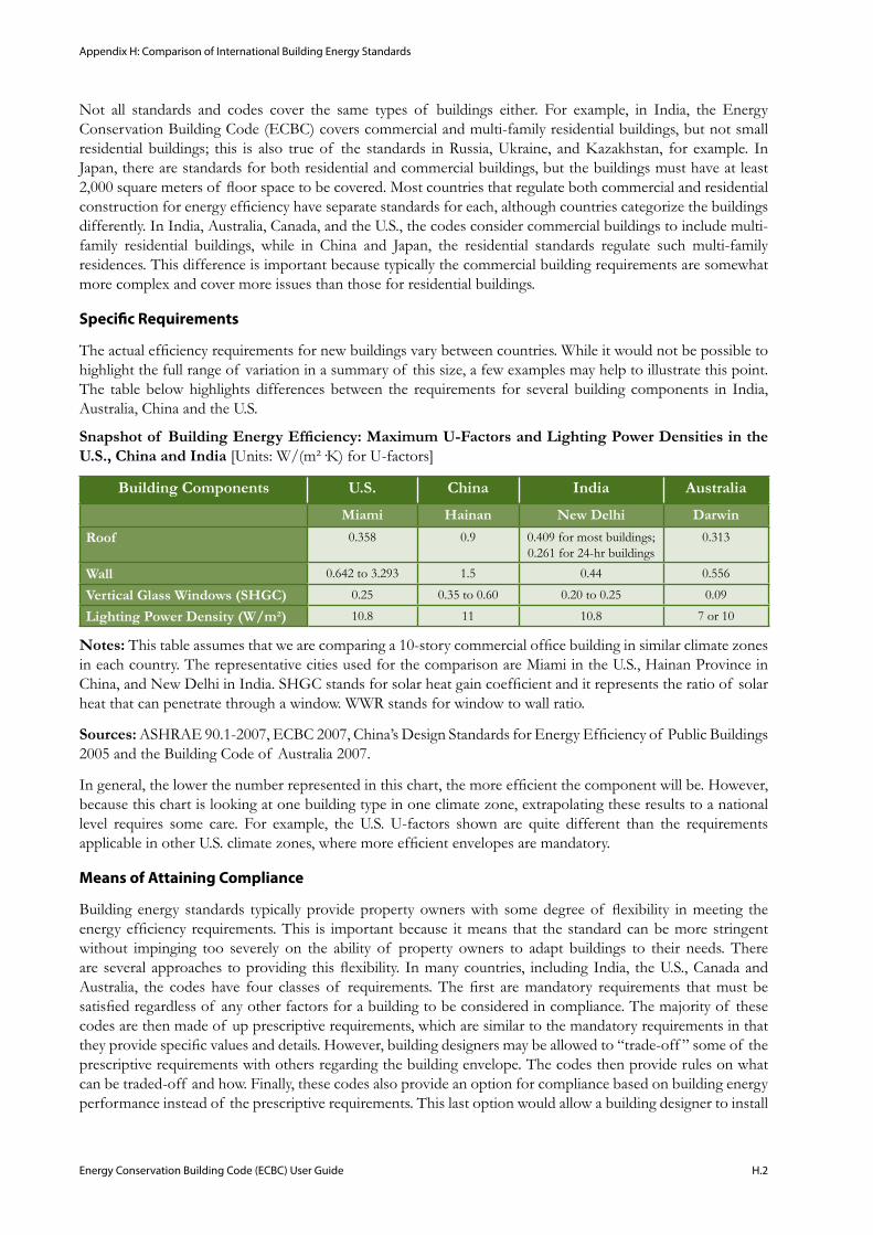
Appendix H: Comparison of International Building Energy Standards
Energy Conservation Building Code (ECBC) User Guide H.2
Not all standards and codes cover the same types of buildings either. For example, in India, the Energy Conservation Building Code (ECBC) covers commercial and multi-family residential buildings, but not small residential buildings; this is also true of the standards in Russia, Ukraine, and Kazakhstan, for example. In Japan, there are standards for both residential and commercial buildings, but the buildings must have at least 2,000 square meters of floor space to be covered. Most countries that regulate both commercial and residential construction for energy efficiency have separate standards for each, although countries categorize the buildings differently. In India, Australia, Canada, and the U.S., the codes consider commercial buildings to include multi-family residential buildings, while in China and Japan, the residential standards regulate such multi-family residences. This difference is important because typically the commercial building requirements are somewhat more complex and cover more issues than those for residential buildings.
Specific Requirements
The actual efficiency requirements for new buildings vary between countries. While it would not be possible to highlight the full range of variation in a summary of this size, a few examples may help to illustrate this point. The table below highlights differences between the requirements for several building components in India, Australia, China and the U.S.
Snapshot of Building Energy Efficiency: Maximum U-Factors and Lighting Power Densities in the U.S., China and India [Units: W/(m²·K) for U-factors]
Building Components U.S. China India Australia
Miami Hainan New Delhi Darwin
Roof 0.358 0.9 0.409 for most buildings; 0.261 for 24-hr buildings
0.313
Wall 0.642 to 3.293 1.5 0.44 0.556
Vertical Glass Windows (SHGC) 0.25 0.35 to 0.60 0.20 to 0.25 0.09
Lighting Power Density (W/m²) 10.8 11 10.8 7 or 10
Notes: This table assumes that we are comparing a 10-story commercial office building in similar climate zones in each country. The representative cities used for the comparison are Miami in the U.S., Hainan Province in China, and New Delhi in India. SHGC stands for solar heat gain coefficient and it represents the ratio of solar heat that can penetrate through a window. WWR stands for window to wall ratio.
Sources: ASHRAE 90.1-2007, ECBC 2007, China’s Design Standards for Energy Efficiency of Public Buildings 2005 and the Building Code of Australia 2007.
In general, the lower the number represented in this chart, the more efficient the component will be. However, because this chart is looking at one building type in one climate zone, extrapolating these results to a national level requires some care. For example, the U.S. U-factors shown are quite different than the requirements applicable in other U.S. climate zones, where more efficient envelopes are mandatory.
Means of Attaining Compliance
Building energy standards typically provide property owners with some degree of flexibility in meeting the energy efficiency requirements. This is important because it means that the standard can be more stringent without impinging too severely on the ability of property owners to adapt buildings to their needs. There are several approaches to providing this flexibility. In many countries, including India, the U.S., Canada and Australia, the codes have four classes of requirements. The first are mandatory requirements that must be satisfied regardless of any other factors for a building to be considered in compliance. The majority of these codes are then made of up prescriptive requirements, which are similar to the mandatory requirements in that they provide specific values and details. However, building designers may be allowed to “trade-off ” some of the prescriptive requirements with others regarding the building envelope. The codes then provide rules on what can be traded-off and how. Finally, these codes also provide an option for compliance based on building energy performance instead of the prescriptive requirements. This last option would allow a building designer to install
Appendix H: Comparison of International Building Energy Standards
Energy Conservation Building Code (ECBC) User Guide H.3
less efficient windows but a more efficient air conditioning system if the total designed energy use falls within the required norms. There are several approaches to establishing the baseline for comparison under the building energy performance method. The UK uses a total carbon footprint of the building (called the Carbon Index Rating)6, the U.S. uses the cost as its reference metric, while some other countries define the characteristics of a reference building for the comparison.
Korea takes a different approach, establishing mandatory requirements and points for a whole range of energy issues related to buildings. Each new building must have a minimum of 60 points. Buildings that exceed the minimum point requirement may be eligible for certain benefits, such as relaxation of certain zoning rules.
Enforcement Systems
Enforcement is critical for the standard to have an effect. Not all countries have mandatory building energy standards. India, for example, has a voluntary code. Japan’s standard is also technically voluntary, although Japan has recently adopted penalties for non-compliance that blur this distinction. The U.S., Canada, and Australia all adopt building standards at the local level. Not all jurisdictions in the U.S. and Canada have adopted their nation’s model building energy code.
Some important issues regarding enforcement and the related impact of the code on energy use include: the point of compliance (design and/or construction stage), how buildings are checked and by whom, penalties and other incentives for compliance, training and information on the code, compliance tools such as code compliance software and inspection checklists, equipment and material testing and ratings.
In the U.S., Canada, Australia, and Korea, for example, the building design must be approved and inspectors check the building for compliance at least once during construction. In Japan, parts of Europe, and the former Soviet Union, the checks only occur at the building design stage. China uses a combination of government employees and certified companies to check building designs and inspect the buildings for compliance. There is no single answer as to which system produces the highest level of compliance. For example, Japanese officials believe that Japan attains a high level of compliance in actual construction because Japan has a very well developed system of training and information dissemination on the building energy standards. Studies in the U.S. have shown that there, physical inspections result in much higher compliance rates.
The stringency of the national system for testing materials and equipment for their energy efficiency properties can also have a marked impact on the final energy consumption of a building. Most countries have a system of certified laboratories that test materials and equipment (like windows and air conditioners), and rate them for efficiency. These ratings then determine if the equipment in a building meets the building energy standard. Testing procedures vary between countries, and there is anecdotal evidence that even in countries with well established systems, ratings can differ by 10% or more based on the testing procedures.
Building energy standard compliance rates vary significantly between countries. What constitutes compliance may also vary, and not all countries consistently publish compliance data. That said, countries usually have lower compliance rates soon after they adopt or revise a standard, and when their enforcement system is not fully developed.
Options for India to Consider
India has taken a purposeful step toward improved building energy efficiency in adopting the Energy Conservation Building Code. The next step is implementing this code, which could require concerted efforts both at the state and national levels. States would need to decide to adopt the code. The national government could also help with this learning process by requiring that all new government buildings meet the building energy code. For example the national government might provide tools to help states and local jurisdictions with enforcement. India has a well-developed system to enforce other types of building codes, and it might use this system for enforcing the building energy code as well. Building energy inspectors at the local level might need training, and local jurisdictions could hire some staff to handle the additional workload. India could also try to simplify the implementation task by developing code compliance software that allows building developers and inspectors to
6 R.E. Horne et al. 2005. International Comparison of Building Energy Performance Standards. Centre for Design, RMIT University, Mel-bourne, Australia.
Appendix H: Comparison of International Building Energy Standards
Energy Conservation Building Code (ECBC) User Guide H.4
easily check the building design for compliance. Such software could also be designed to automatically develop inspection checklists. As India gains experience with implementing its code, it might want to modify the code periodically. Many countries have found that establishing a regular timetable for such modifications can allow many stakeholders to have input into the process, which in turn, makes the code more feasible to implement. Indian consumers could benefit from this process as the energy costs in new buildings decline at the same time that the environmental footprint of these buildings grows smaller.
Appendix I: References
Energy Conservation Building Code (ECBC) User Guide I.1
APPENDIX I: ReferencesA. Bhatia: “1. Course Content (PDH 149), HVAC Design Aspects: Choosing a Right System-Central V/s Compact Systems”, Herndon, USA
ASHRAE/ANSI standard 62 (2004), “2. Ventilation for Acceptable Indoor Air Quality”, American Society of Heating, Refrigerating, and Air-conditioning Engineers, Atlanta, USA
ASHRAE / ANSI Standard 55 (2004), “3. Thermal Environmental Conditions for Human Occupancy”, American Society of Heating, Refrigerating, and Air-conditioning Engineers, Atlanta, USA
ASHRAE Handbook (2005): “4. Fundamentals (SI)”, American Society of Heating, Refrigerating, and Air-conditioning Engineers, Inc., www.ashrae.org, Atlanta, GA, USA
ASHRAE (2004, 2007): “5. 90.1 User Manual-ANSI/ASHRAE/IESNA Standard 90.1-2004”, American Society of Heating, Refrigerating, and Air-conditioning Engineers, Inc., www.ashrae.org, Atlanta, GA, USA
ASHRAE (2004): “6. Energy Standard for Buildings Except Low-Rise Residential Buildings”, American Society of Heating, Refrigerating, and Air-conditioning Engineers, Inc., www.ashrae.org, Atlanta, GA, USA
Bansal and Minke(1988), “7. Climatic zones and rural housing in India”, India
Bureau of Energy Efficiency, Ministry of Power, Government of India (2007): “8. Energy Conservation Building Code (ECBC)-Revised Version May 2008”, New Delhi, India
Bureau of Energy Efficiency, Ministry of Power, Government of India (2005): “9. Energy Efficiency in Electrical Utilities”, New Delhi, India
Bureau of Indian Standard (2005): “10. National Building Code of India, Second Revision 2005”, New Delhi, India
Donald R. Wulfinghoff (1999): “11. Energy Efficiency Manual”, Energy Institute Press, Wheaton, Maryland, USA
Dr. Ardeshir Madhavi (1995): “12. Fundamentals of Building Physics”, Carnegie Mellon University, Pittsburgh, USA
E Source (2005): “13. E Source Technology Atlas Series- Volume I: Lighting, Volume II: Commercial Space Cooling and Air Handling, Volume IV: Drive Power”, Boulder, CO, USA.
Goetzler W (2007): “14. Variable Refrigerant Flow Systems”, ASHRAE Journal 49 (4)
Krishan et al. (2001): “15. Climate responsive architecture”, A design handbook for energy efficient buildings, School of Planning & Architecture (SPA), New Delhi, India
Ministry of Power (2001): “16. Energy Conservation Act”, www.powermin.nic.in, New Delhi, India.
Morrison F. (2004): “17. What’s up with Cooling Tower”, ASHRAE Journal 46 (7), USA.
Nayak and Prajapati (2006): “18. Handbook on Energy Conscious Buildings”, IIT Bombay, Bombay, India
Stein, B., Reynolds, J., Grondzik W., & Kwok, A (2005). “19. Mechanical and Electrical Equipment for Buildings”, 10th Ed. John Wiley & Sons Inc.
U.S. Department of Energy: “20. EnergyPlus Energy Simulation Weather Data”, www.eere.energy.gov, Washington DC
US Green Building Council (2006), “21. LEED for new Construction, Reference Guide, Version 2.2, Third Edition”, www.usgbc.org, Washington, DC, USA
USAID ECO-III Project: “22. Energy Conservation Building Code Tip Sheet; Envelope, Lighting, HVAC, & Energy Simulation”, www.eco3.org, New Delhi, India
Web References:
Southface Energy Institute, www.southface.org, 241 Pine Street NE, Atlanta, USA1.


USAID ECO-III ProjectInternational Resources Group
AADI Building, Lower Ground Floor 2, Balbir Saxena Marg, Hauz Khas, New Delhi-110016, India
Phone: +91-11-2685-3110; Email: [email protected]; Web Site: www.eco3.org