Embed Size (px)
Citation preview
ECE 301 – Digital Electronics
Multiple-bit Adder Circuits
(Lecture #13)
The slides included herein were taken from the materials accompanying Fundamentals of Logic Design, 6th Edition, by Roth and Kinney,
and were used with permission from Cengage Learning.
Spring 2011 ECE 301 - Digital Electronics 2
Multiple-bit Adder Circuits
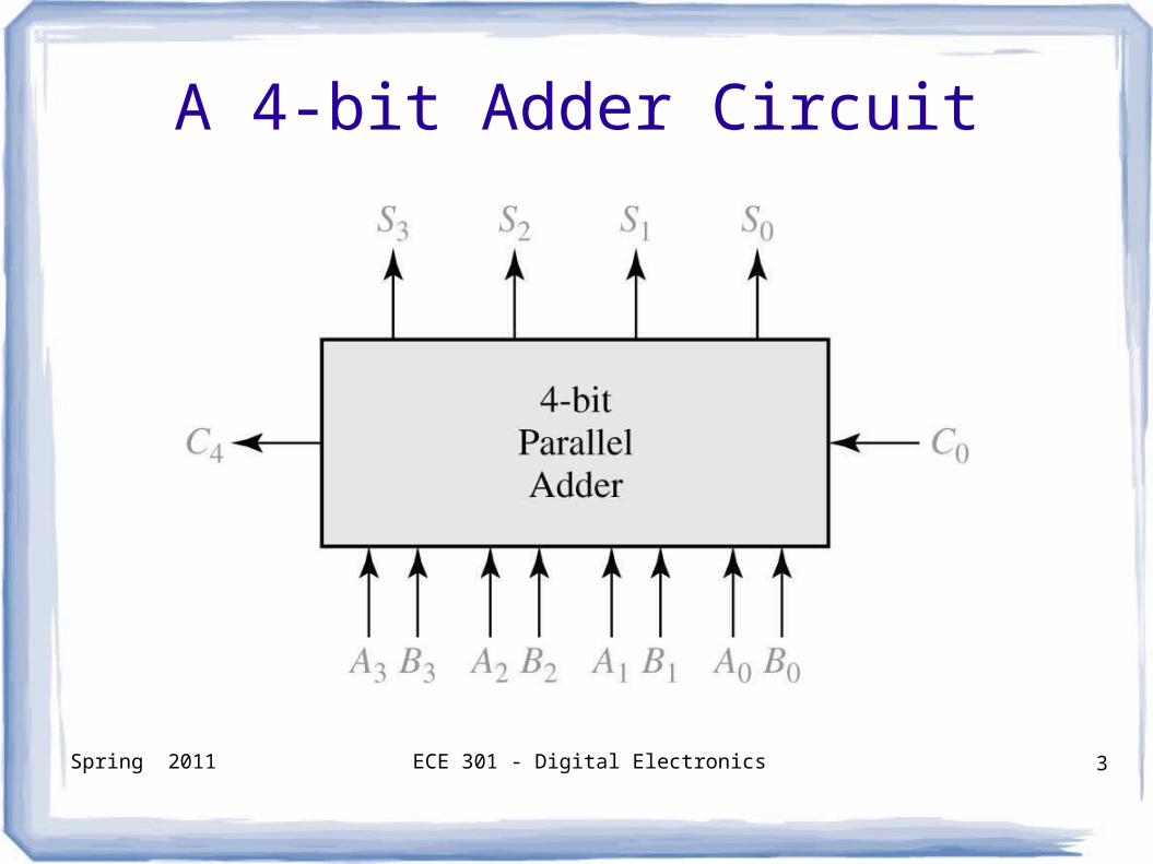
How do you design a combinational logic circuit to add two 4-bit binary numbers?
Spring 2011 ECE 301 - Digital Electronics 3
A 4-bit Adder Circuit
Spring 2011 ECE 301 - Digital Electronics 4
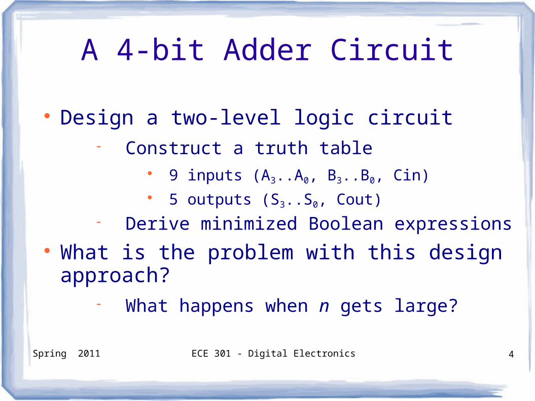
A 4-bit Adder Circuit
Design a two-level logic circuit Construct a truth table
9 inputs (A3..A0, B3..B0, Cin) 5 outputs (S3..S0, Cout)
Derive minimized Boolean expressions What is the problem with this design approach?
What happens when n gets large?
Spring 2011 ECE 301 - Digital Electronics 5
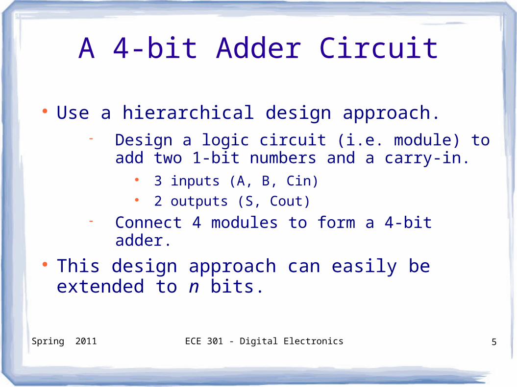
A 4-bit Adder Circuit
Use a hierarchical design approach. Design a logic circuit (i.e. module) to add two
1-bit numbers and a carry-in. 3 inputs (A, B, Cin) 2 outputs (S, Cout)
Connect 4 modules to form a 4-bit adder. This design approach can easily be extended
to n bits.
Spring 2011 ECE 301 - Digital Electronics 6
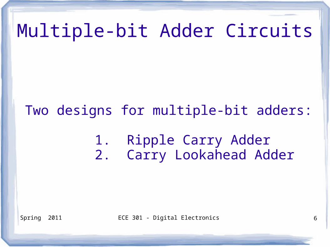
Two designs for multiple-bit adders:
1. Ripple Carry Adder2. Carry Lookahead Adder
Multiple-bit Adder Circuits
Spring 2011 ECE 301 - Digital Electronics 7
Ripple Carry Adder
Spring 2011 ECE 301 - Digital Electronics 8
Ripple Carry Adder
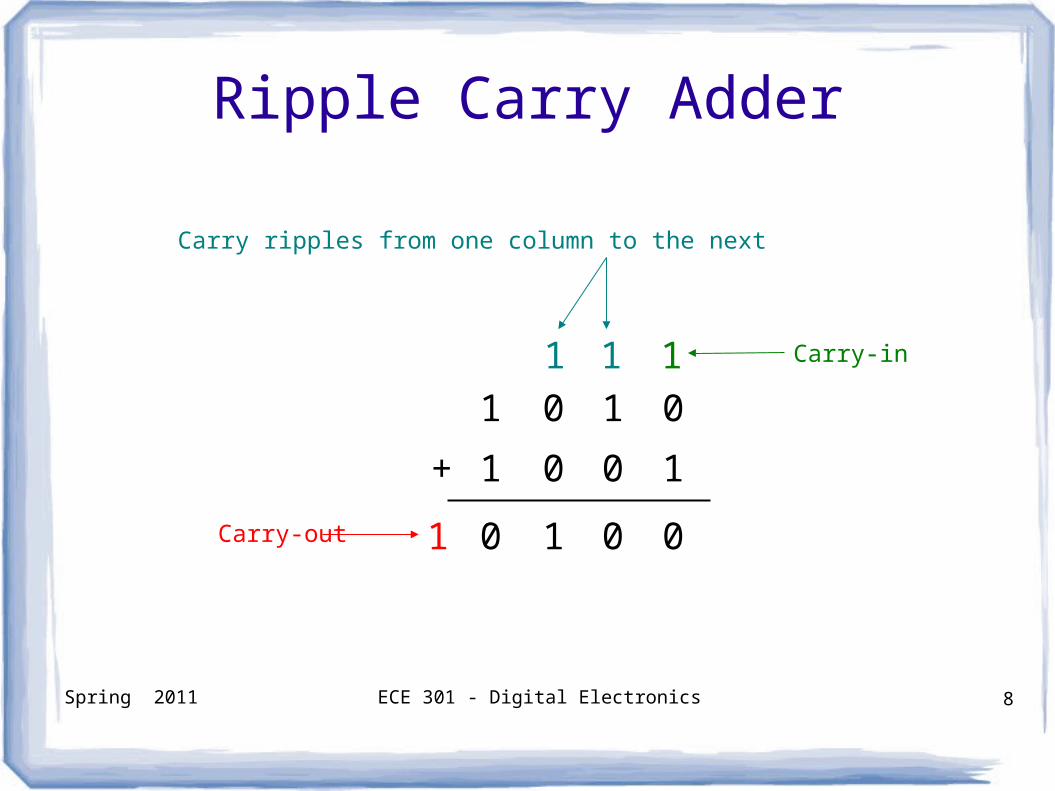
1 0 1 0
1 0 0 1+
1 Carry-in
0 1 0 01Carry-out
11
Carry ripples from one column to the next
Spring 2011 ECE 301 - Digital Electronics 9
Ripple Carry Adder
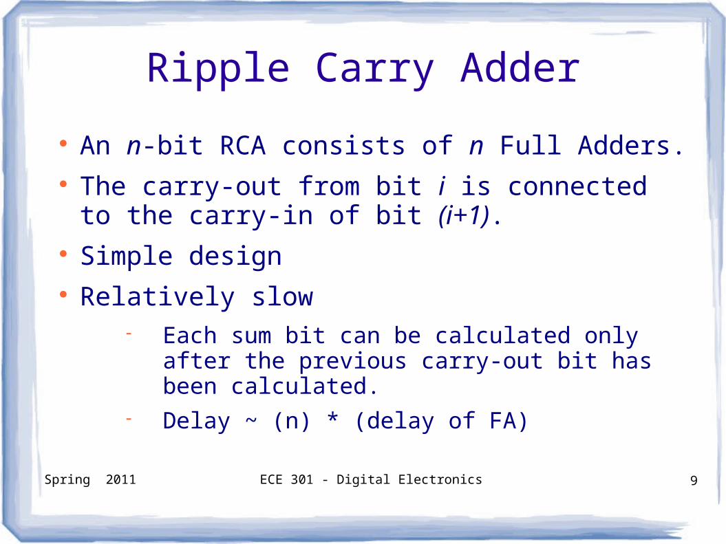
An n-bit RCA consists of n Full Adders. The carry-out from bit i is connected to the
carry-in of bit (i+1). Simple design Relatively slow
Each sum bit can be calculated only after the previous carry-out bit has been calculated.
Delay ~ (n) * (delay of FA)
Spring 2011 ECE 301 - Digital Electronics 10
Ripple Carry Adder
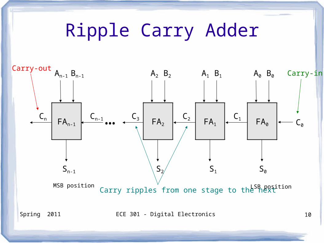
C0
C1C2… C3Cn-1Cn
S0
A0 B0
Carry-out
Carry ripples from one stage to the next
Carry-in
LSB positionMSB position
A1 B1A2 B2An-1 Bn-1
S1S2Sn-1
FAn-1 FA2 FA1 FA0
Spring 2011 ECE 301 - Digital Electronics 11
Multiple-bit Adder Circuits
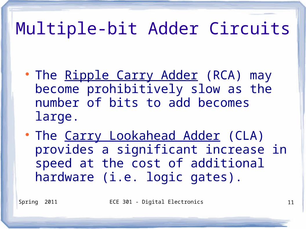
The Ripple Carry Adder (RCA) may become prohibitively slow as the number of bits to add becomes large.
The Carry Lookahead Adder (CLA) provides a significant increase in speed at the cost of additional hardware (i.e. logic gates).
Spring 2011 ECE 301 - Digital Electronics 12
Carry Lookahead Adder
Spring 2011 ECE 301 - Digital Electronics 13
Carry Lookahead Adder
1 0 0 1
0 0 1 1+
1
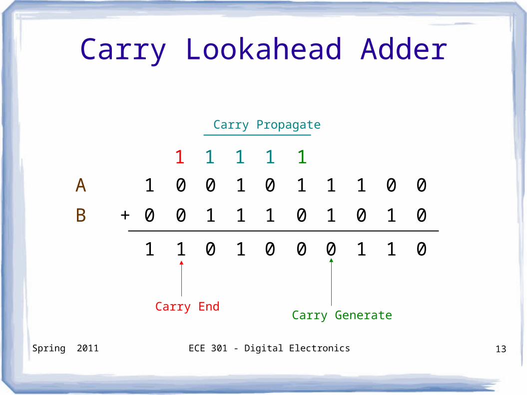
Carry Generate
1 1 0 1
Carry End
11
Carry Propagate
0 1 1 1
1 0 1 0
0 0 0 1
0 0
1 0
1 0
11
A
B
Spring 2011 ECE 301 - Digital Electronics 14
Carry Lookahead Adder
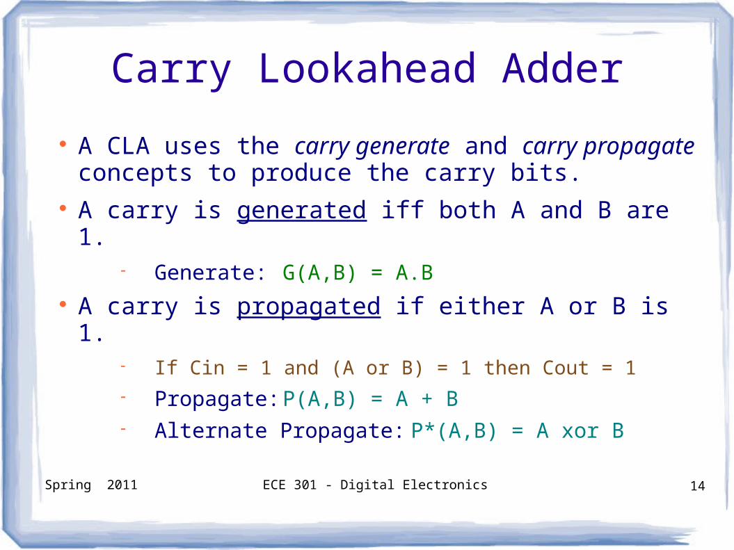
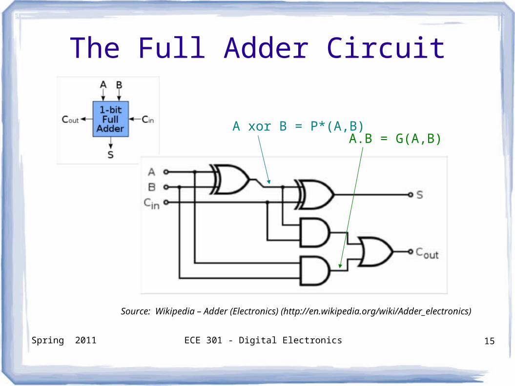
A CLA uses the carry generate and carry propagate concepts to produce the carry bits.
A carry is generated iff both A and B are 1. Generate: G(A,B) = A.B
A carry is propagated if either A or B is 1. If Cin = 1 and (A or B) = 1 then Cout = 1
Propagate: P(A,B) = A + B Alternate Propagate: P*(A,B) = A xor B
Spring 2011 ECE 301 - Digital Electronics 15
The Full Adder Circuit
A xor B = P*(A,B)A.B = G(A,B)
Source: Wikipedia – Adder (Electronics) (http://en.wikipedia.org/wiki/Adder_electronics)
Spring 2011 ECE 301 - Digital Electronics 16
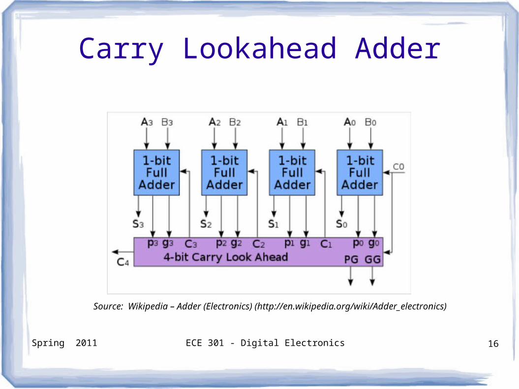
Carry Lookahead Adder
Source: Wikipedia – Adder (Electronics) (http://en.wikipedia.org/wiki/Adder_electronics)
Spring 2011 ECE 301 - Digital Electronics 17
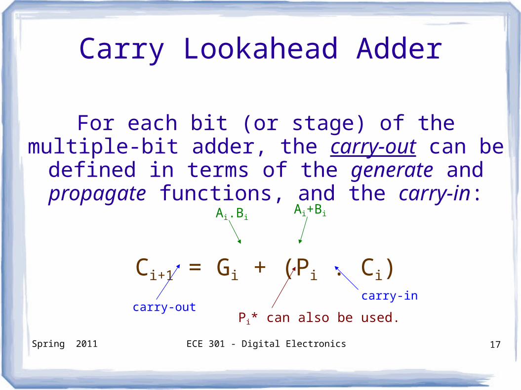
Carry Lookahead Adder
For each bit (or stage) of the multiple-bit adder, the carry-out can be defined in terms of the generate
and propagate functions, and the carry-in:
Ci+1 = Gi + (Pi . Ci)
carry-outcarry-in
Pi* can also be used.
Ai.BiAi+Bi
Spring 2011 ECE 301 - Digital Electronics 18
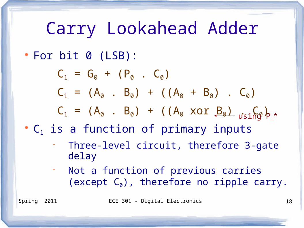
Carry Lookahead Adder For bit 0 (LSB):
C1 = G0 + (P0 . C0)
C1 = (A0 . B0) + ((A0 + B0) . C0)
C1 = (A0 . B0) + ((A0 xor B0) . C0) C1 is a function of primary inputs
Three-level circuit, therefore 3-gate delay Not a function of previous carries (except
C0), therefore no ripple carry.
using Pi*
Spring 2011 ECE 301 - Digital Electronics 19
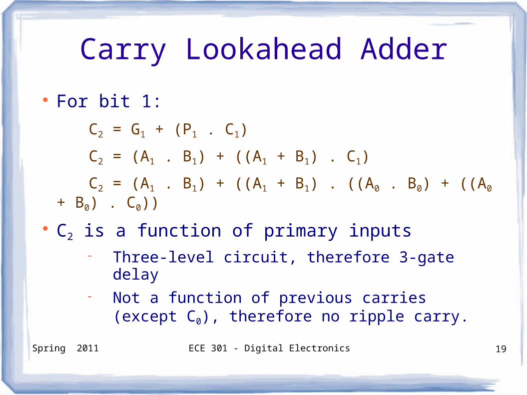
Carry Lookahead Adder
For bit 1:
C2 = G1 + (P1 . C1)
C2 = (A1 . B1) + ((A1 + B1) . C1)
C2 = (A1 . B1) + ((A1 + B1) . ((A0 . B0) + ((A0 + B0) . C0))
C2 is a function of primary inputs Three-level circuit, therefore 3-gate delay Not a function of previous carries (except
C0), therefore no ripple carry.
Spring 2011 ECE 301 - Digital Electronics 20
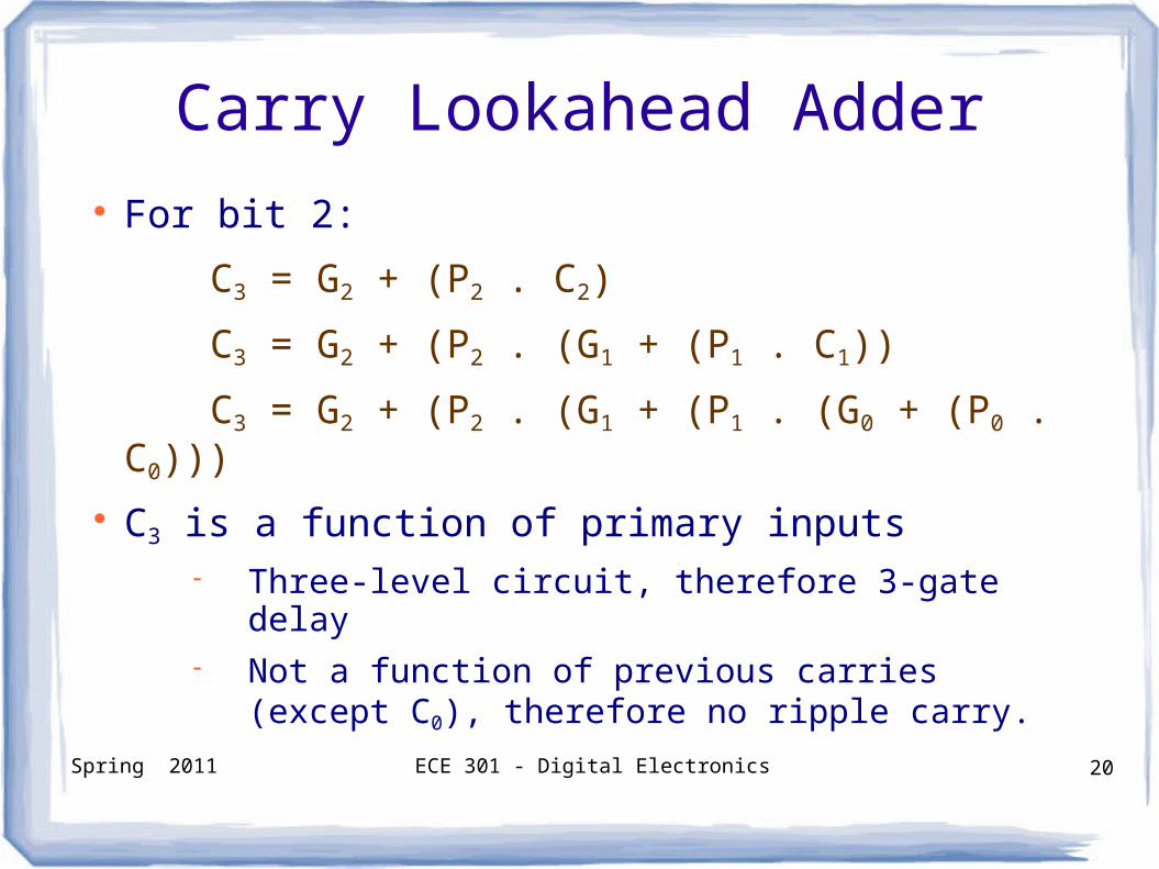
Carry Lookahead Adder
For bit 2:
C3 = G2 + (P2 . C2)
C3 = G2 + (P2 . (G1 + (P1 . C1))
C3 = G2 + (P2 . (G1 + (P1 . (G0 + (P0 . C0))) C3 is a function of primary inputs
Three-level circuit, therefore 3-gate delay Not a function of previous carries (except
C0), therefore no ripple carry.
Spring 2011 ECE 301 - Digital Electronics 21
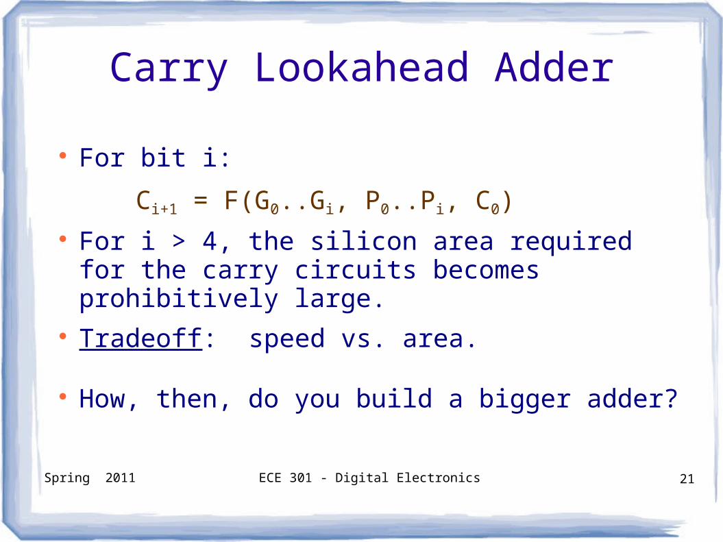
Carry Lookahead Adder
For bit i:
Ci+1 = F(G0..Gi, P0..Pi, C0) For i > 4, the silicon area required for the carry
circuits becomes prohibitively large. Tradeoff: speed vs. area.
How, then, do you build a bigger adder?
Spring 2011 ECE 301 - Digital Electronics 22
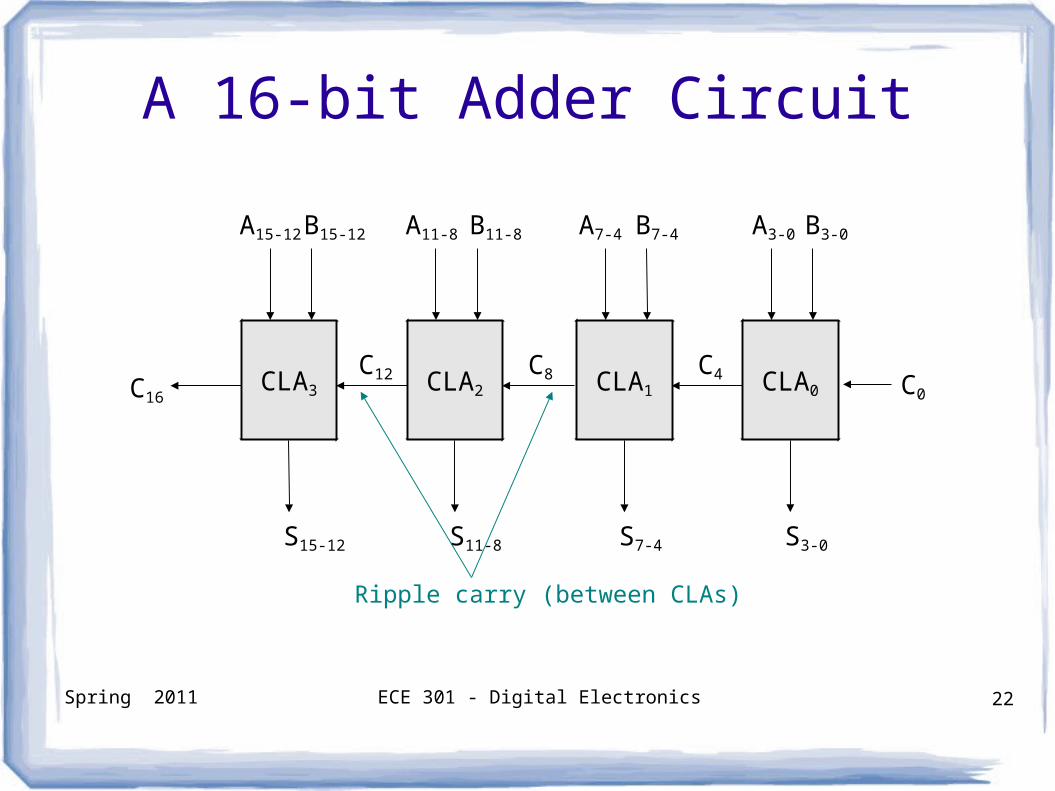
A 16-bit Adder Circuit
C0
C4C8C12C16
S3-0
A3-0 B3-0A7-4 B7-4
S7-4
A11-8 B11-8
S11-8
A15-12 B15-12
S15-12
Ripple carry (between CLAs)
CLA3 CLA2 CLA1 CLA0
Spring 2011 ECE 301 - Digital Electronics 23
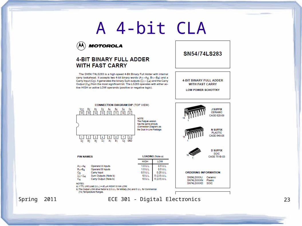
A 4-bit CLA(Standard Component)
Spring 2011 ECE 301 - Digital Electronics 24
Multiple-bit Adder/Subtractor Circuit
Spring 2011 ECE 301 - Digital Electronics 25
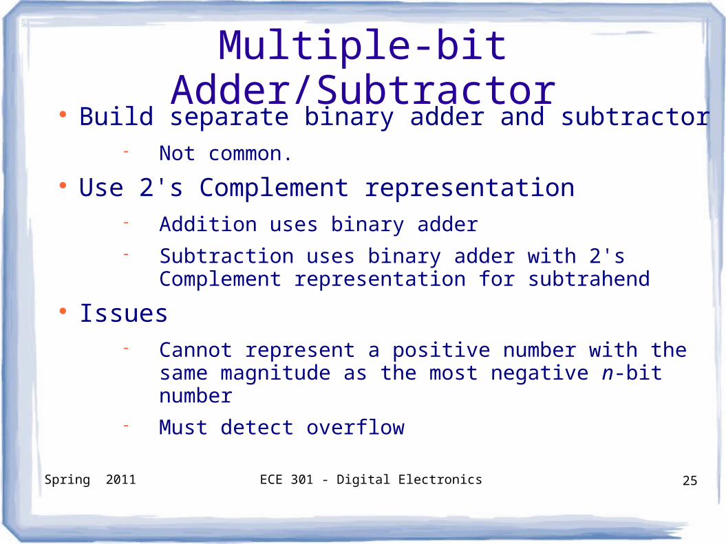
Multiple-bit Adder/Subtractor Build separate binary adder and subtractor
Not common.
Use 2's Complement representation Addition uses binary adder Subtraction uses binary adder with 2's
Complement representation for subtrahend
Issues Cannot represent a positive number with the same
magnitude as the most negative n-bit number Must detect overflow
Spring 2011 ECE 301 - Digital Electronics 26
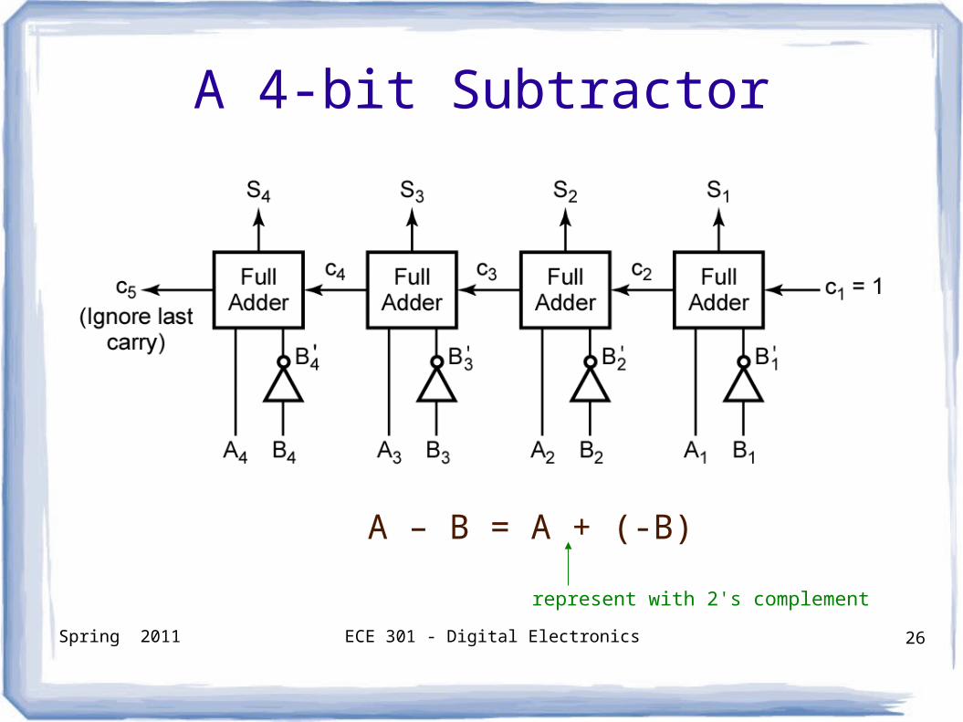
A 4-bit Subtractor
A – B = A + (-B)
represent with 2's complement
Spring 2011 ECE 301 - Digital Electronics 27
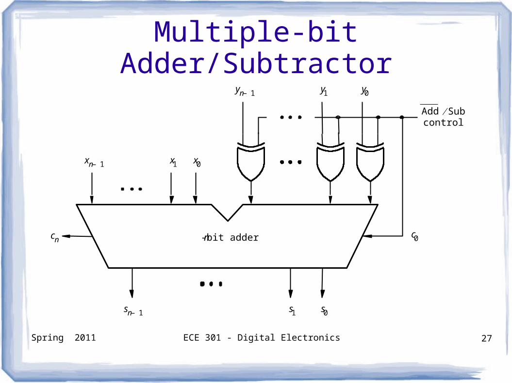
Multiple-bit Adder/Subtractor
s 0 s 1 s n 1 –
x 0 x 1 x n 1 –
c n n -bit adder
y 0 y 1 y n 1 –
c 0
Add Sub control
Spring 2011 ECE 301 - Digital Electronics 28
Detecting Overflow
Spring 2011 ECE 301 - Digital Electronics 29
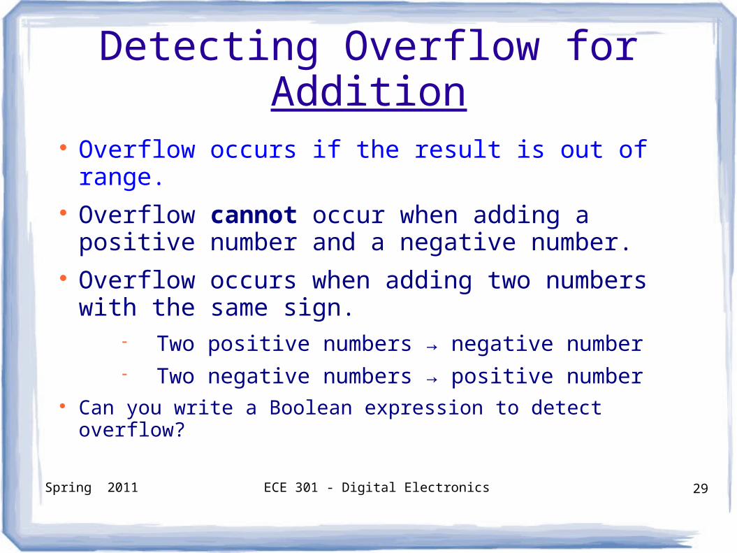
Detecting Overflow for Addition
Overflow occurs if the result is out of range. Overflow cannot occur when adding a positive
number and a negative number. Overflow occurs when adding two numbers
with the same sign. Two positive numbers → negative number Two negative numbers → positive number
Can you write a Boolean expression to detect overflow?
Spring 2011 ECE 301 - Digital Electronics 30
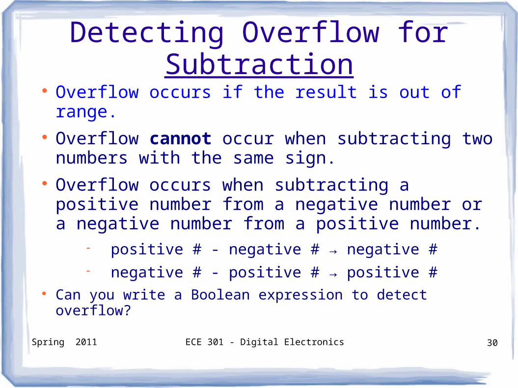
Detecting Overflow for Subtraction Overflow occurs if the result is out of range. Overflow cannot occur when subtracting two
numbers with the same sign. Overflow occurs when subtracting a positive
number from a negative number or a negative number from a positive number.
positive # - negative # → negative # negative # - positive # → positive #
Can you write a Boolean expression to detect overflow?
Spring 2011 ECE 301 - Digital Electronics 31
Questions?