Embed Size (px)
Citation preview
Human PowerThe Technical Journal of the
International Human-Powered VehicleAssociation
David Gordon Wilson, Editor21 Winthrop Street
Winchester, MA 01890-2851, U.S.A.(617) 729-2203 (home)(617) 253-5121 (MIT)
Associate EditorsToshio Kataoka - Japan
1-7-2-818 Hiranomiya-MachiHirana-ku, Osaka-shi, Japan 547
Theodor Schmidt, EuropeRebackerweg 19
CH-4402 FrenkendorfSWITZERLAND
Philip Thiel, Watercraft4720 7th Avenue, NE
Seattle, WA 98105 USAIHPVA
P.O. Box 51255Indianapolis, IN 46251 USA
(317) 876-9478
Dave KennedyAdam EnglundBruce RosenstielMarti DailyPaul MacCreadyDoug MillikenGlen ColeChris RoperMatteo MartignoniTheodor SchmidtAllan AbbottMarti DailyPeter ErnstDave KennedyChet KyleGardner MartinDennis TavesDavid Gordon Wilson
PresidentSecretaryTreasurerExec. Dir.Int'l PresidentVP WaterVP LandVP AirVP All-terrainVP Hybrid PowerBoard Members
Human Power is published quarterly by theInternational Human-Powered Vehicle Assoc.,Inc., (IHPVA) a non-profit organization devotedto the study & application of human muscularpotential to propel craft through the air, in thewater and on land. Membership information isavailable by sending a self-addressed, stampedbusiness-sized envelope to the IHPVA addresslisted above.
Members may purchase additonal copies ofHuman Power for $3.50 each. Non-members maypurchase copies for $5.00 per copy.
Material in Human Power is copyrighted bythe IHPVA. Unless copyrighted by the author(s),complete articles or representative excerpts maybe published elsewhere if full credit to both theauthor(s) and the IHPVA is prominently given.
Special thanks to the authors, Marti Daily,Carolyn Stitson and Leah McGavern, withoutwhom this issue would not have been possible.
EditorialsA sense of (human) power
In no way can the editorship ofHuman Power be regarded as a bullypulpit. We are not read by the masses, butby a small, highly intelligent, far-sightedgroup of individuals. (It's always easy tobe complimentary about one's own group- but I think that these descriptions are nottoo far wide of the mark). Therefore it isperhaps not too remarkable that within aweek of the last issue coming out I hadtwo responses, from Doug Milliken andPhil Thiel, to an editorial suggestion aboutthe need for more research on varioustopics. I hope that we will have room forboth comments in this issue. In the sameweek Toshio Kataoka responded to thesuggestion that we have more specialissues of Human Power by sendingmaterial for one that could be devoted totopics on human-powered helicopters. Inview of the great efforts that are beingmade by several groups to win the HP-helicopter prizes, a special issue would behighly appropriate. We need morematerial: please respond as enthusiasti-cally as you did to the last editorial bysending in contributions. And MichaelEliasohn has almost finished puttingtogether what should be nearly a specialissue on front-wheel-drive front-steeringrecumbents. We have a feast in store!
Rapid and generous responses likethese could go to an editor's head. Onewonders what hobby-horses one couldmention that would produce instantresults? Here are two.
In the old days of wind-up watchesthere were people who maintained that
In this issue-The Airglow human-powered aircraft,Chris RoperPedaling with paddlewheels or how tobuild your own, Robert FearingEditorialsLetters, reviewPedal-power on the French canals, Philip ThielChoosing a hull shape for a pedal-powered boat, Shields BishopA propeller design process for human-pow-ered marine vehicles, Patrick KI PooleFlat-tire directional performance,Doug MillikenLeg sweepout volume, drag-and cooling? 1Paddlin' Madeline, Philip ThielConversion factorsRoyal Aeronautucial Society Human-Powered Flight Conference, Chris RoperAround the world in the human-voweredyacht, Donald Spaulding
2 Human Power 9/1 spring 1991
they could not wear wrist watches becausesomething about their bodies' staticelectricity or magnetic fields prevented thewatches from ticking. I found it difficult tobelieve them. There has been a longcorrespondence in the magazine of theFCOT-the Fellowship of Cycling OldTimers-on the old equivalent of cyclo-computers, the Lucas odometer, mountedon the front-wheel spindle with a five-pointed star wheel that was driven aroundby a striker on one of the spokes. Somepeople had no trouble with them, whileothers remembered that they never gotmore than a few hundred miles out ofthem before they failed. What is relevant tothese stories is that my sixth cyclo-computer has just frozen up. I haverepeatedly bought new makes and modelshoping that I will arrive at one that willlast a year and give me good data on howlong my tires and chains last, but therealways comes a time when whatever newmodel I've bought just refuses to respondto any input. With some of them I've beenable to restart them by taking out the cellsand losing all my data, and with othersnothing will revive them. Sending themback to the manufacturers usually gets afriendly and uninformative letter and anequally disappointing replacement. Am Ithe equivalent of the people who couldn'twear wrist watches, or do other peoplehave similar experiences? If so, why?
My second topic on which I wouldenjoy having reaction, and perhaps a fullpaper, is on aluminum-alloy components.My crank snapped as I was riding hometonight. I have had many aluminum-alloycomponents fail similarly on manybicycles, regular and recumbent, over mymany years of riding, but someone wroteto me recently who far surpassed me incrank failures. I have preached beforeabout the dangers from fatigue failure ofaluminum-alloy frames and particularlyforks. We know that aluminum has nofatigue limit as does steel: eventually allaluminum components should, therefore,fail in fatigue, however low the loading."Alloy" solid cranks were developed as alighter-weight substitute for solid steelcranks. One conclusion might be todevelop tubular lightweight steel-alloycranks. But then sometimes I find myselfflying in a DC3, and reflecting that thesewere first built in around 1936 and havebeen used for short-hop trips involvingmany take-off-and-landing stresses andlow-level bumpy flights, and yet the wingsdon't break off. Nor does anyone proposesteel airplanes, despite events like theAloha tragedy in which part of thefuselage blew away after a fatigue failure.High-performance aircraft are using
I
Pedal-power on the French canalsby Philip Thiel
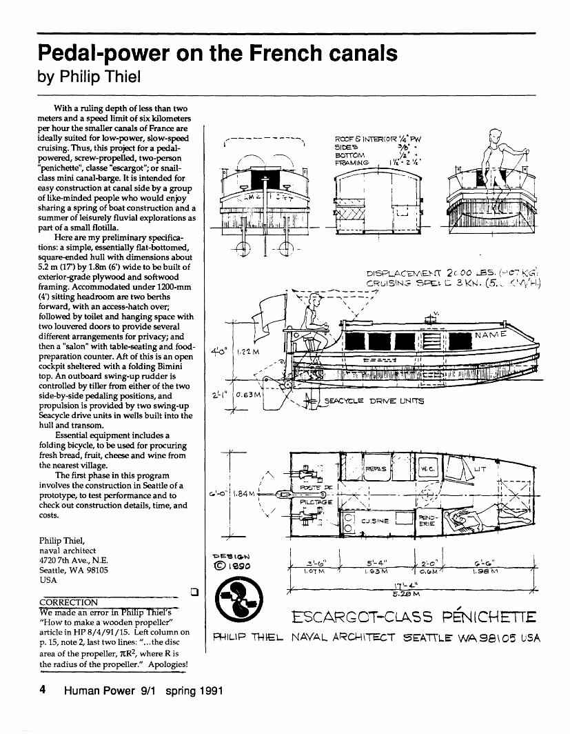
With a ruling depth of less than twometers and a speed limit of six kilometersper hour the smaller canals of France areideally suited for low-power, slow-speedcruising. Thus, this project for a pedal-powered, screw-propelled, two-person"penichette", classe "escargot"; or snail-class mini canal-barge. It is intended foreasy construction at canal side by a groupof like-minded people who would enjoysharing a spring of boat construction and asummer of leisurely fluvial explorations aspart of a small flotilla.
Here are my preliminary specifica-tions: a simple, essentially flat-bottomed,square-ended hull with dimensions about5.2 m (17') by 1.8m (6') wide to be built ofexterior-grade plywood and softwoodframing. Accommodated under 1200-mm(4') sitting headroom are two berthsforward, with an access-hatch over;followed by toilet and hanging space withtwo louvered doors to provide severaldifferent arrangements for privacy; andthen a "salon" with table-seating and food-preparation counter. Aft of this is an opencockpit sheltered with a folding Biminitop. An outboard swing-up rudder iscontrolled by tiller from either of the twoside-by-side pedaling positions, andpropulsion is provided by two swing-upSeacycle drive units in wells built into thehull and transom.
Essential equipment includes afolding bicycle, to be used for procuringfresh bread, fruit, cheese and wine fromthe nearest village.
The first phase in this programinvolves the construction in Seattle of aprototype, to test performance and tocheck out construction details, time, andcosts.
Philip Thiel,naval architect4720 7th Ave., N.E.Seattle, WA 98105USA
OCORRECTIONWe made an error in Philip Thiel's"How to make a wooden propeller"article in HP 8/4/91/15. Left column onp. 15, note 2, last two lines: "...the disc
area of the propeller, KR2, where R isthe radius of the propeller." Apologies!
_
I IRCOF 1NTERIoR /4WSIDES :1/' BOSTON\ ./2 U0rul Y 1:S2.
rtsPLACNEM\E-,' T 2c 00 JC. (C7:CRUSN5 L: _kN. (5> K <VY-L)
Ca'. .84 M
_Ileso
fi
.07T M a5'- 4"l. G3 M
2-C Iv
5.22 M
ESCAR G OT-C LAS SPF:ILIP THIEL NAVAL ARCH\TECT EA7LE WA98\C5 USA
4 Human Power 9/1 spring 1991
1. 98 A
PENICHEE
= j r . - -. , --- . -
I__
CG,, '
I
A propeller design process for human-poweredmarine vehiclesBy Patrick K. Poole
AbstractA propeller blade design process for
human-powered marine vehicles ispresented. The process described is basedon simple momentum theory modified toaccount for the energy lost in the rotationalmotion prevalent in low-speed propellersand typical of those in human-poweredpropulsion. The process gives the designera complete mechanism to generaterelatively high-efficiency blades specifi-cally suited for their individual applicationwhile allowing for a variety of designoptions.
IntroductionHigh-efficiency screw-type propellers
suitable for human-powered marineapplications are of limited availability.This fact became apparent during thedesign process of the U.S. NavalAcademy's entry in the 1st AnnualInternational Human-Powered SubmarineRace sponsored by the H.A. Perry Founda-tion. The event was held at Riviera Beach,Florida in June of 1989. An effort to locate apropeller that was ideally suited for oursubmarine proved fruitless and necessi-tated an original design. At the competi-tion it was noted that only a few otherentries had specifically designed propellerswhile many resorted to modifyingavailable off-the-shelf propellers with littleregard to efficiency. The Naval Academy'sentry, SQUID, incorporated a contra-rotating propeller of in-house designwhich proved to be extremely efficient.The design method was based on momen-tum theory, modified to account for therotational energy lost in the swirlingmotion of the propeller wake. That processis described in the following paper givinga complete mechanism for developingblade shapes from inputs of engine power,Er, mechanical efficiency, N, and bladehub and tip diameters, D,, and D,,, andpropeller RPM.
DiscussionGenerally, propeller designers attempt
to minimize the propeller's non-thrustflow energy. Two major losses of energyoccurring in the conversion of shaft powerto thrust power in screw type propellersare 1) the inability of the exit flow toadequately diffuse its energy to thesurrounding medium (kinetic energy loss)
and, 2) the swirling motion of the flowcaused by the rotation of the blade(rotational energy loss). Momentum theoryaccounts for the kinetic energy loss anddesigns based on this theory are generallyaccurate for high-speed applications, butless so otherwise. Using momentumtheory for low-speed applications willresult in actual efficiencies less that thosepredicted by the theory. The designprocess presented herein modifies momen-tum theory to account for the rotationalenergy loss making it more applicable inthe mid and low-speed ranges. Followingthe design flow chart, figure 1, and usingthe presented equations should result in apropeller efficiency as predicted for aspecifically identified vehicle operating atdesign conditions.
Throughout the process there aresome general comments that the designershould keep in mind:
1) The larger the propeller diameter thegreater the efficiency.2) Slow-speed propellers have highrotational energy losses3) High-speed propellers have highkinetic energy losses.4) A sufficiently large diameter canovercome items 2 & 3.
A,. E, ()
Dm - -... . . ~ a '
( ) ( ) IV., 77, Satlsfactory-
Select A(r) Diet. -V.. , . - Eat. 8(r), t(r)Select r
(11) (10)I (X,., )
p caculate(xy, ) (12) (13) Select offteta (13)
(x, .y, ) Calculate '
(x.y) upper urface line (
(x,y) lower surface line } -
Figure 1. Design process flow diagram
Design process and equationsFollowing the step-by-step process
below will result in the blade shapegeometry in the form of (x, y, z) coordi-nates of the high and low pressuresurfaces. The x-coordinate is in thedirection of blade motion, the y-coordinateis the axial direction with the positivebeing forward and negative aft, and z-coordinate is in the radial, or r, direction
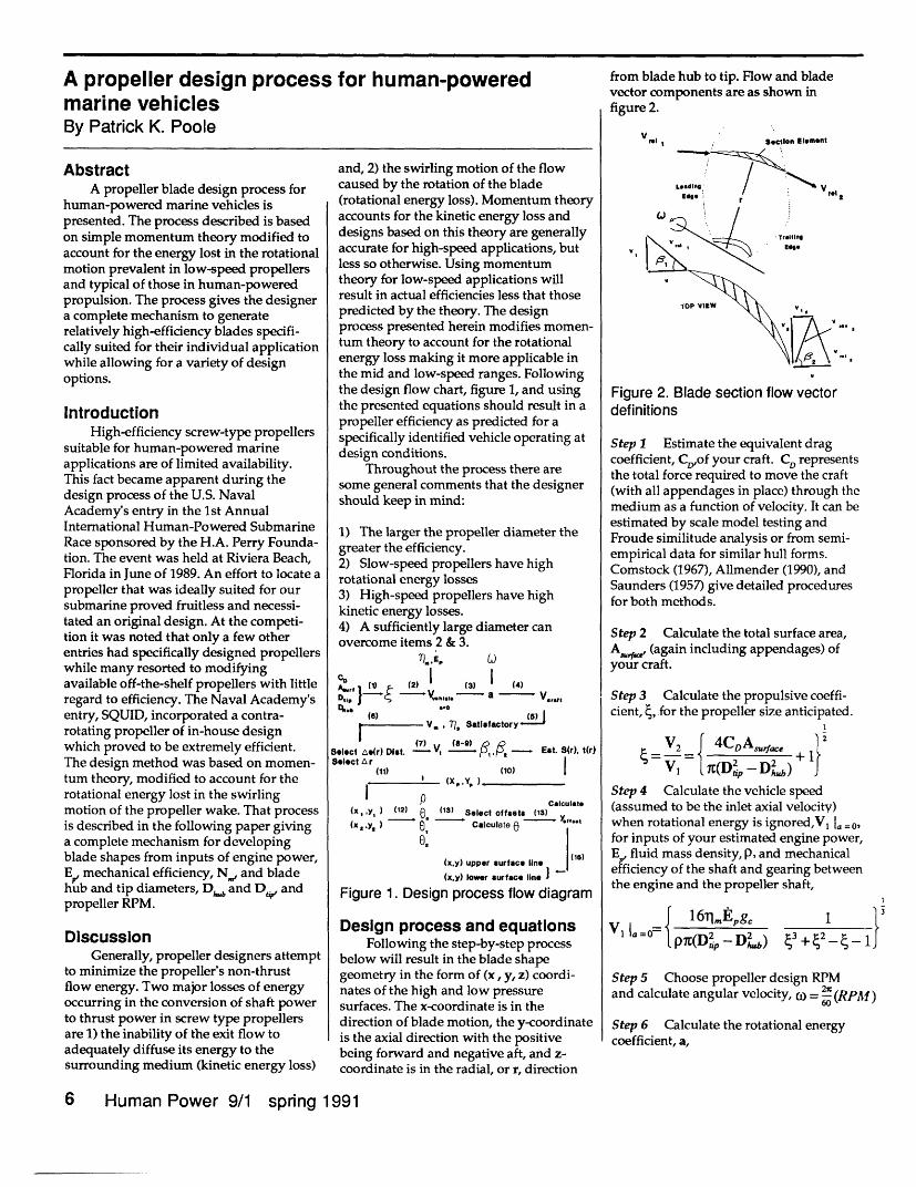
from blade hub to tip. Flow and bladevector components are as shown infigure 2.
V.l 1 SeCtion Element
LEedien , Vr
TOP viEW
Figure 2. Blade section flow vectordefinitions
Step 1 Estimate the equivalent dragcoefficient, CD,of your craft. CD representsthe total force required to move the craft(with all appendages in place) through themedium as a function of velocity. It can beestimated by scale model testing andFroude similitude analysis or from semi-empirical data for similar hull forms.Comstock (1967), Allmender (1990), andSaunders (1957) give detailed proceduresfor both methods.
Step 2 Calculate the total surface area,A_,¢, (again including appendages) ofyour craft.
Step 3 Calculate the propulsive coeffi-cient, S, for the propeller size anticipated.
V2 n -4CDA,, }
Step 4 Calculate the vehicle speed(assumed to be the inlet axial velocity)when rotational energy is ignored,V I = 0,for inputs of your estimated engine power,E fluid mass density, P, and mechanicalefficiency of the shaft and gearing betweenthe engine and the propeller shaft,
J 1 6m,,EpgpiT(Dp - D , ) + 2 -1}
4 +42_4_ 1'Step 5 Choose propeller design RPMand calculate angular velocity, = 0 (RPM)
Step 6 Calculate the rotational energycoefficient, a,
6 Human Power 9/1 spring 1991
8gclT.Epa=
PO(Dip + Dhb)CDAscc.(Vl 1I=0)2
Step 7 Calculate the craft speed, V,
V= 16. _,g,pC(D2 -D )2 l (+('- -+ 1) ( + a)
Step 8 Calculate the propulsive effi-ciency, lp 1
lip 2
1 + (- 1)
Step 9 Adjust RPM and blade diametersto optimize Tip and Vcrepeating steps 2-7.
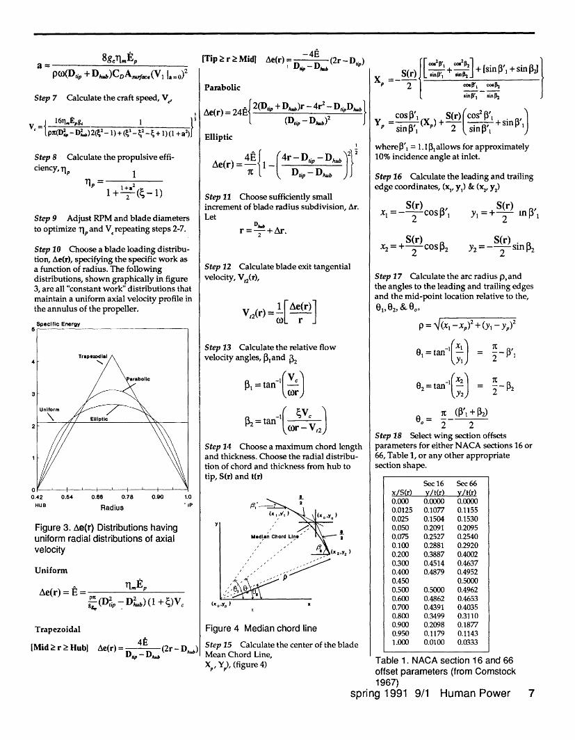
Step 10 Choose a blade loading distribu-tion, Ae(r), specifying the specific work asa function of radius. The followingdistributions, shown graphically in figure3, are all "constant work" distributions thatmaintain a uniform axial velocity profile inthe annulus of the propeller.
Specific Energy
0.54 0.66 0.78
Radius
0.90 1.0* P
Figure 3. Ae(r) Distributions havinguniform radial distributions of axialvelocity
Uniform
Ae(r) = E =P ( -D ,) (1 + )VcBe, ti, - hu
Trapezoidal
[Mid 2 r Hub] Ae(r) = D.D (2r- D,b)
[Tip > r 2 Midi Ae(r) n n.. (2r -D,)/n -p n. -P
Parabolic
Ae(r) = 24E{ 2(D, + Df b)r -4r2 - Dip,, (Dq, - D) 2
Elliptic
4E (Ae(r) =- 1- IC
4r - D, - Db 2
Dtip - Dhub
Step 11 Choose sufficiently smallincrement of blade radius subdivision, Ar.Let
r= =-+ Ar.
Step 12 Calculate blade exit tangentialvelocity, Vt2(r),
V 2(r) = 1[Ar]
Step 13 Calculate the relative flowvelocity angles, Pand S2
1 = tan-I
a = tan-(c0-V2)
Step 14 Choose a maximum chord lengthand thickness. Choose the radial distribu-tion of chord and thickness from hub totip, S(r) and t(r)
I2
2'y2)
Figure 4 Median chord line
Step 15 Calculate the center of the blaMean Chord Line,Xp, Y), (figure 4)
de
S(r) [ ,d-o, 2 ] + [sin y, + sin } iXP 2 CsI, Co54
cos (X + S(r) (cos2 sin Y snp(Xl,)+ sin[ ,'inf',
where3', = 1.l 31allows for approximately10% incidence angle at inlet.
Step 16 Calculate the leading and trailingedge coordinates, (xl, y1) & (x2, y2)
= S(r) COS
2
x=+ COsI2
S(r)y =+-- min P'1
S(r)Y2 =-2 sin ,32
Step 17 Calculate the arc radius p,andthe angles to the leading and trailing edgesand the mid-point location relative to the,
01,02, & 00o,
p = (x,- xp) -+ (y- y)2
XI(X01= t-')
02 = tan - (Xy21
2
2
0°= 2 2Step 18 Select wing section offsetsparameters for either NACA sections 16 or66, Table 1, or any other appropriatesection shape.
Table 1. NACA section 16 and 66offset parameters (from Comstock1967)
spring 1991 9/1 Human Power 7
0.42
HUB
Sec 16 Sec 66x/S(r) yv/t(r) y/t(r)0.000 0.0000 0.00000.0125 0.1077 0.11550.025 0.1504 0.15300.050 0.2091 0.20950.075 0.2527 0.25400.100 0.2881 0.29200.200 0.3887 0.40020.300 0.4514 0.46370.400 0.4879 0.49520.450 0.50000.500 0.5000 0.49620.600 0.4862 0.46530.700 0.4391 0.40350.800 0.3499 0.31100.900 0.2098 0.18770.950 0.1179 0.11431.000 0.0100 0.0333
YY - z
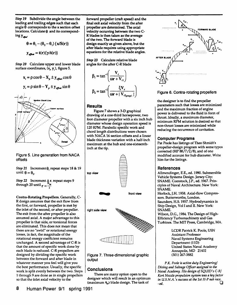
Step 19 Subdivide the angle between theleading and trailing edges such that eachangle 0 corresponds to the x section offsetlocations. Calculate 0 and its correspond-ing y.,
6 = 01 - (02- 01) {x/S(r)}
Yap, = t(r){ylt(r)}
Step 20 Calculate upper and lower bladesurface coordinates, (x, y,), figure 5.
xi = p cos - X + yo Cos 0
y = psin - ± y, sin - Yp
kIodI. Chord LI..
Upper urfe
\ '0
Figure 5. Line generation from NACAoffsets
Step 21 Increment 0, repeat steps 18 & 19until 0 = 02.
Step 22 Increment A r. repeat steps 9through 20 until r =D
2
Contra-Rotating Propellers. Generally, C-R design assumes that the exit flow fromthe first, or forward, propeller is met bythe inlet of the second, or after propeller.The exit from the after propeller is alsoassumed axial. A major advantage to thispropeller is that side, or torsional forcesare eliminated. This does not mean thatthere are no "swirl" or rotational energylosses, in fact, the magnitude of therotational energy coefficient remainsunchanged. A second advantage of C-R isthat the amount of specific work done byeach blade is reduced. C-R propellers aredesigned by dividing the specific workbetween the forward and after blade inwhatever manner you feel will give youthe best performance. Usually, the specificwork is split evenly between the two. Steps1 through 9 are done as in single propellersso that the inlet axial velocity to the
forward propeller (craft speed) and thefinal exit axial velocity from the afterpropeller are determined. The axialvelocity occurring between the two C-R blades is then taken as the averageof the two. The forward blade isdesign exactly as given above, but theafter blade requires using appropriateequations for the relative blade angles.
Step 23 Calculate relative bladeangles for the after C-R blade
PI = tan(rI c VyJ
r + I V,2pp 1IJ
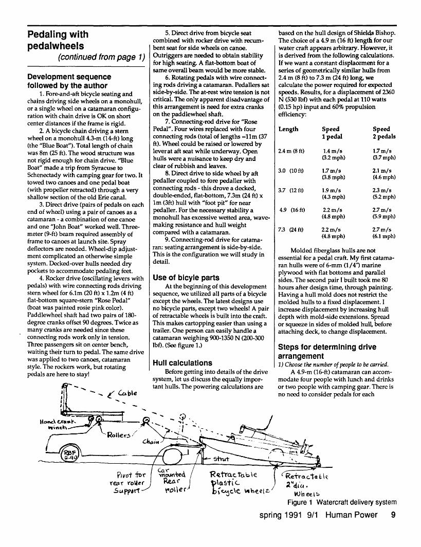
ResultsFigure 7 shows a 3-D graphical
drawing of a one-third horsepower, twofoot diameter propeller with a six inch hubdiameter whose design operation speed is120 RPM. Parabolic specific work andchord length distributions were chosenwith NACA 16 section offsets and a linearblade thickness variation with a half-inchmaximum at the hub and one-sixteenth-inch at the tip.
top view
front view
right side view
Figureoutput
7. Three-dimensional graphic
ConclusionsThere are many option open to the
designer which will result in an optimum(maximum tl,) blade design. The task of
8 Human Power 9/1 spring 1991
V
..---.....-FORMRD BLADE
V .
V.,·YI
AFTER I
v v,
vi A
v.0_
Figure 6. Contra-rotating propellers
the designer is to find the propellerparameters such that losses are minimizedand the maximum fraction of enginepower is delivered to the fluid in form ofthrust. Ideally, a maximum diameter,minimum RPM solution is desired so thatnon-thrust losses are minimized whilereducing the occurrence of cavitation.
Computer ProgramsPat Poole has listings of Theo Shmidt'spropeller-design program with some typoscorrected (HP 88/7/2/8), and of onemodified account for hub diameter. Writehim for the listings.
ReferencesAllmendinger, E.E., ed. 1990. SubmersibleVehicle Systems Design. Jersey City:SNAME. Comstock, J.P., ed. 1967. Prin-ciples of Naval Architecture. New York:SNAME.Horlock, J.H. 1958. Axial-flow Compres-sors. Butterworths, London.Saunders, H.S. 1957. Hydrodynamics inShip Design, Vol I and II. New York:SNAME.Wilson, D.G., 1984. The Design of High-Efficiency Turbomachinery and GasTurbines. The MIT Press, Cambridge, MA.
LCDR Patrick K. Poole, USNAssistant ProfessorNaval Systems EngineeringDepartment (11D)United States Naval AcademyAnnapolis, MD 21402(301) 267-3882
P.K. Poole is active duty Engineering/Diving and Salvage Officer assigned to theNaval Academy. His design of SQUID's C-RIKort Nozzle propulsion system was a key factorin U.S.N.A.'s success at the 1st H-P sub race.-ed. U
v
7if.'
Pedaling withpedalwheels
(continued from page 1)
Development sequencefollowed by the author
1. Fore-and-aft bicycle seating andchains driving side wheels on a monohull,or a single wheel on a catamaran configu-ration with chain drive is OK on shortcenter distances if the frame is rigid.
2. A bicycle chain driving a sternwheel on a monohull 4.3-m (14-ft) long(the "Blue Boat"). Total length of chainwas 8m (25 ft). The wood structure wasnot rigid enough for chain drive. "BlueBoat" made a trip from Syracuse toSchenectady with camping gear for two. Ittowed two canoes and one pedal boat(with propeller retracted) through a veryshallow section of the old Erie canal.
3. Direct drive (pairs of pedals on eachend of wheel) using a pair of canoes as acatamaran - a combination of one canoeand one "John Boat" worked well. Three-meter (9-ft) beam required assembly offrame to canoes at launch site. Spraydeflectors are needed. Wheel-dip adjust-ment complicated an otherwise simplesystem. Decked-over hulls needed drypockets to accommodate pedaling feet.
4. Rocker drive (oscillating levers withpedals) with wire connecting rods drivingstern wheel for 6.1m (20 ft) x 1.2m (4 ft)flat-bottom square-stern "Rose Pedal"(boat was painted rosie pink color).Paddlewheel shaft had two pairs of 180-degree cranks offset 90 degrees. Twice asmany cranks are needed since theseconnecting rods work only in tension.Three passengers sit on center bench,waiting their turn to pedal. The same drivewas applied to two canoes, catamaranstyle. The rockers work, but rotatingpedals are here to stay!
5. Direct drive from bicycle seatcombined with rocker drive with recum-bent seat for side wheels on canoe.Outriggers are needed to obtain stabilityfor high seating. A flat-bottom boat ofsame overall beam would be more stable.
6. Rotating pedals with wire connect-ing rods driving a catamaran. Pedallers satside-by-side. The at-rest wire tension is notcritical. The only apparent disadvantage ofthis arrangement is need for extra crankson the paddlewheel shaft.
7. Connecting-rod drive for "RosePedal". Four wires replaced with fourconnecting rods (total of lengths =11m (37ft). Wheel could be raised or lowered bylever at aft seat while underway. Openhulls were a nuisance to keep dry andclear of rubbish and leaves.
8. Direct drive to side wheel by aftpedaller coupled to fore pedaller withconnecting rods - this drove a decked,double-ended, flat-bottom, 7.3m (24 ft) xIm (3ft) hull with "foot pit" for nearpedaller. For the necessary stability amonohull has excessive wetted area, wave-making resistance and hull weightcompared with a catamaran.
9. Connecting-rod drive for catama-ran: seating arrangement is side-by-side.This is the configuration we will study indetail.
Use of bicyle partsAt the beginning of this development
sequence, we utilized all parts of a bicycleexcept the wheels. The latest designs useno bicycle parts, except two wheels! A pairof retractable wheels is built into the craft.This makes cartopping easier than using atrailer. One person can easily handle acatamaran weighing 900-1350 N (200-300lbf). (See figure 1.)
Hull calculations- I- ... . 1I _:1 - - .1 ·tetore getting into aetalls o te crnve
system, let us discuss the equally impor-
-_ ( CZcbIe
based on the hull design of Shields Bishop.The choice of a 4.9 m (16 ft) lengtfi for ourwater craft appears arbitrary. However, itis derived from the following calculations.If we want a constant displacement for aseries of geometrically similar hulls from2.4 m (8 ft) to 7.3 m (24 ft) long, wecalculate the power required for expectedspeeds. Results, for a displacement of 2360N (530 lbf) with each pedal at 110 watts(0.15 hp) input and 60% propulsionefficiency:
Length
2.4 m (8 ft)
Speed1 pedal
1.4 m/s(3.2 mph)
3.0 (10 ft) 1.7 m/s(3.8 mph)
3.7 (12 ft) 1.9 m/s(4.3 mph)
4.9 (16 ft) 2.2 m/s(4.8 mph)
7.3 (24 ft) 2.2 m/s(4.8 mph)
Speed2 pedals
1.7 m/s(3.7 mph)
2.1 m/s(4.6 mph)
23 m/s(52 mph)
2.7 m/s(5.9 mph)
2.7 m/s(6.1 mph)
Molded fiberglass hulls are notessential for a pedal craft. My first catama-ran hulls were of 6-mm (1/4') marineplywood with flat bottoms and parallelsides. The second pair I built took me 80hours after design time, through painting.Having a hull mold does not restrict themolded hulls to a fixed displacement. Iincrease displacement by increasing hulldepth with mold-side extensions. Spreador squeeze in sides of molded hull, beforeattaching deck, to change displacement.
Steps for determining drivearrangement1) Choose the number of people to be carried.
A 4.9-m (16-ft) catamaran can accom-modate four people with lunch and drinks
:amping gear. There ispedals for each
Figure 1 Watercraft delivery system
spring 1991 9/1 Human Power 9
I14)
_ . 1,·.
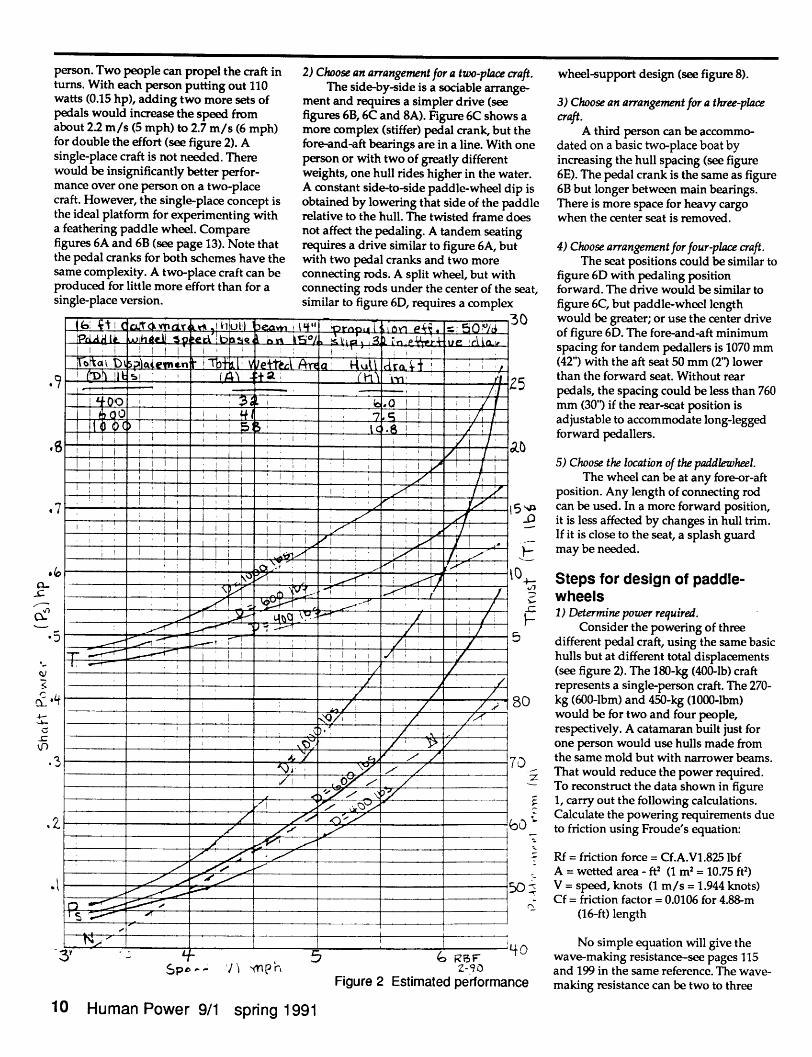
person. Two people can propel the craft inturns. With each person putting out 110watts (0.15 hp), adding two more sets ofpedals would increase the speed fromabout 2.2 m/s (5 mph) to 2.7 m/s (6 mph)for double the effort (see figure 2). Asingle-place craft is not needed. Therewould be insignificantly better perfor-mance over one person on a two-placecraft. However, the single-place concept isthe ideal platform for experimenting witha feathering paddle wheel. Comparefigures 6A and 6B (see page 13). Note thatthe pedal cranks for both schemes have thesame complexity. A two-place craft can beproduced for little more effort than for asingle-place version.
0
4--,-
2) Choose an arrangement for a two-place craft.The side-by-side is a sociable arrange-
ment and requires a simpler drive (seefigures 6B, 6C and 8A). Figure 6C shows amore complex (stiffer) pedal crank, but thefore-and-aft bearings are in a line. With oneperson or with two of greatly differentweights, one hull rides higher in the water.A constant side-to-side paddle-wheel dip isobtained by lowering that side of the paddlerelative to the hull. The twisted frame doesnot affect the pedaling. A tandem seatingrequires a drive similar to figure 6A, butwith two pedal cranks and two moreconnecting rods. A split wheel, but withconnecting rods under the center of the seat,similar to figure 6D, requires a complex
J*i At i C, itc ', -i3 '-"--' _ i t _,
:3 _ ; -; ' I t I
10 _ '0 . abI I I ) l I I l , I Th, I . .1i v I / , i
7 Ll , , 5_ I i,
D t< < 5
-it Q iI : e / v
2 i :l;> -
, " -.5 '
RF
3Y~~~~~~~~~~~___~ S~~~~B Figure 2 Estimated pe-9oFigure 2 Estimated performance
wheel-support design (see figure 8).
3) Choose an arrangement for a three-placecraft.
A third person can be accommo-dated on a basic two-place boat byincreasing the hull spacing (see figure6E). The pedal crank is the same as figure6B but longer between main bearings.There is more space for heavy cargowhen the center seat is removed.
4) Choose arrangement for four-place craft.The seat positions could be similar to
figure 6D with pedaling positionforward. The drive would be similar tofigure 6C, but paddle-wheel lengthwould be greater; or use the center driveof figure 6D. The fore-and-aft minimumspacing for tandem pedallers is 1070 mm(42") with the aft seat 50 mm (2') lowerthan the forward seat. Without rearpedals, the spacing could be less than 760mm (30') if the rear-seat position isadjustable to accommodate long-leggedforward pedallers.
5) Choose the location of the paddlewheel.The wheel can be at any fore-or-aft
position. Any length of connecting rodcan be used. In a more forward position,it is less affected by changes in hull trim.If it is close to the seat, a splash guardmay be needed.
Steps for design of paddle-
wheels_ 1) Determine power required.
Consider the powering of threedifferent pedal craft, using the same basichulls but at different total displacements(see figure 2). The 180-kg (400-lb) craftrepresents a single-person craft. The 270-kg (600-lbm) and 450-kg (1000-lbm)would be for two and four people,respectively. A catamaran built just forone person would use hulls made fromthe same mold but with narrower beams.That would reduce the power required.To reconstruct the data shown in figure1, carry out the following calculations.Calculate the powering requirements dueto friction using Froude's equation:
Rf = friction force = Cf.A.V1.825 lbfA = wetted area - ft2 (1 m2 = 10.75 ft2)V = speed, knots (1 m/s = 1.944 knots)Cf = friction factor = 0.0106 for 4.88-m
(16-ft) length
No simple equation will give thewave-making resistance-see pages 115and 199 in the same reference. The wave-
e making resistance can be two to three
10 Human Power 9/1 spring 1991
SP, v -M L
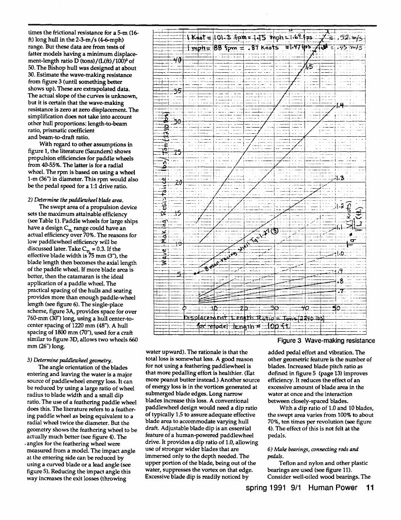
times the frictional resistance for a 5-m (16-ft) long hull in the 2-3-m/s (4-6-mph)range. But these data are from tests offatter models having a minimum displace-ment-length ratio D (tons)/(L(ft)/100)3 of50. The Bishop hull was designed at about30. Estimate the wave-making resistancefrom figure 3 (until something bettershows up). These are extrapolated data.The actual slope of the curves is unknown,but it is certain that the wave-makingresistance is zero at zero displacement. Thesimplification does not take into accountother hull proportions: length-to-beamratio, prismatic coefficientand beam-to-draft ratio.
With regard to other assumptions infigure 1, the literature (Saunders) showspropulsion efficiencies for paddle wheelsfrom 40-55%. The latter is for a radialwheel. The rpm is based on using a wheel1-m (36") in diameter. This rpm would alsobe the pedal speed for a 1:1 drive ratio.
2) Determine the paddlewheel blade area.The swept area of a propulsion device
sets the maximum attainable efficiency(see Table 1). Paddle wheels for large shipshave a design CT. range could have anactual efficiency over 70%. The reasons forlow paddlewheel efficiency will bediscussed later. Take C. = 0.3. If theeffective blade width is 75 mm (3"), theblade length then becomes the axial lengthof the paddle wheel. If more blade area isbetter, then the catamaran is the idealapplication of a paddle wheel. Thepractical spacing of the hulls and seatingprovides more than enough paddle-wheellength (see figure 6). The single-placescheme, figure 3A, provides space for over760-mm (30") long, using a hull center-to-center spacing of 1220 mm (48"). A hullspacing of 1800 mm (70"), used for a craftsimilar to figure 3D, allows two wheels 660mm (26") long.
3) Determine paddlewheel geometry.The angle orientation of the blades
entering and leaving the water is a majorsource of paddlewheel energy loss. It canbe reduced by using a large ratio of wheelradius to blade width and a small dipratio. The use of a feathering paddle wheeldoes this. The literature refers to a feather-ing paddle wheel as being equivalent to aradial wheel twice the diameter. But thegeometry shows the feathering wheel to beactually much better (see figure 4). Theangles for the feathering wheel weremeasured from a model. The impact angleat the entering side can be reduced byusing a curved blade or a lead angle (seefigure 5). Reducing the impact angle thisway increases the exit losses (throwing
T-~ i-----4-- _---r-
.r .- _ I____ _ __x,_ _2. _> ;, .
-t~~~~~~~~~~~~~~ 4 1 _..__J._* -4 :: . ... : .. _:: , !t- . ..._i___ ___ I- _ - __ ___ ,._ _ __ ___.__tt_, p 7Vnu +4846iZA- f at;.___ __ I __i__ _ _ ____.A ,_.... ._
.-. ~ ...... ,- -' ,-- -. , ,. -..-_ - ---- 1 t -, .... t -- :-- --.-- :----- -...
__ iii: t _____ _... __.._._-_ *f.._...,X
:I -I .-- - -- -x :---_ ---- '- -- ------- r- --- - -.A , ·--51- __i. _. -- =- _ .: :;_ .--- 1 --. -- --- ---- -- -- --* .t./ -_. -.- 1 ·- .--- ~ .---- ----- 1------- :
. _."/i-- _ .. --- i-- :t - .- _ i ..'-:- ._ -_ _ . _,-----t ----.--.__s---E· . - ,_ . ... ~ ,- , ,, . ,/ ---.-- ---I - ----- -.. - .1_ ............. / -_ t X .....-.... ..... ......... '" _ . " --
_-A. .a; . .__ . ,_". .... . . .____ ...... _ __ ._Cb . __ / j ' ' ' -' ' z ~~~~~: .... , __ . . i ....._, .. _._. . . .- ' 1 --....
~- - :_-~: _ I . . . . -- r~ - -"'': ''1-- e - s x, - - - -i .-;~ .--- ,1 ---- 2 ;i/- ----- i _j _ -{ -: ._ --- -- - *- - - o ; --.Do; -_-~ :-- .f ;: . ./ --: . .- :1: : -- _ X .,- ::: .~----Y __Lv..... ....i.''-....__ , ..... ,_ -, : ., , , 4 ..........._ ___ .......- - . ---
~-~---~-----C~~~~~~--~- -¥-- ---t---~~ . '~ " ~' ..._-3 T i ---- ) ~-*-. --C:C- -I----- --- - a- - ---- -- - -~- -- -I --t ... -ta--- t!- - ------ f -~ I- -!----i- --- -/ ,- ,IT -- ..,--- -- 1 - --- 1\-t
I~~~~_ . - - .- _ _
_ _ '-
- i .1 I,
1: --- , --- H
A --- ?-·
I---- th
FS--, 19
water upward). The rationale is that thetotal loss is somewhat less. A good reasonfor not using a feathering paddlewheel isthat more pedalling effort is healthier. (Eatmore peanut butter instead.) Another sourceof energy loss is in the vortices generated atsubmerged blade edges. Long narrowblades increase this loss. A conventionalpaddlewheel design would need a dip ratioof typically 1.5 to assure adequate effectiveblade area to accommodate varying hulldraft. Adjustable blade dip is an essentialfeature of a human-powered paddlewheeldrive. It provides a dip ratio of 1.0, allowinguse of stronger wider blades that areimmersed only to the depth needed. Theupper portion of the blade, being out of thewater, suppresses the vortex on that edge.Excessive blade dip is readily noticed by
~~~- -----.
- - c~~~~~-
Figure 3 Wave-making resistance
added pedal effort and vibration. Theother geometric feature is the number ofblades. Increased blade pitch ratio asdefined in figure 5 (page 13) improvesefficiency. It reduces the effect of anexcessive amount of blade area in thewater at once and the interactionbetween closely-spaced blades.
With a dip ratio of 1.0 and 10 blades,the swept area varies from 100% to about70%, ten times per revolution (see figure4). The effect of this is not felt at thepedals.
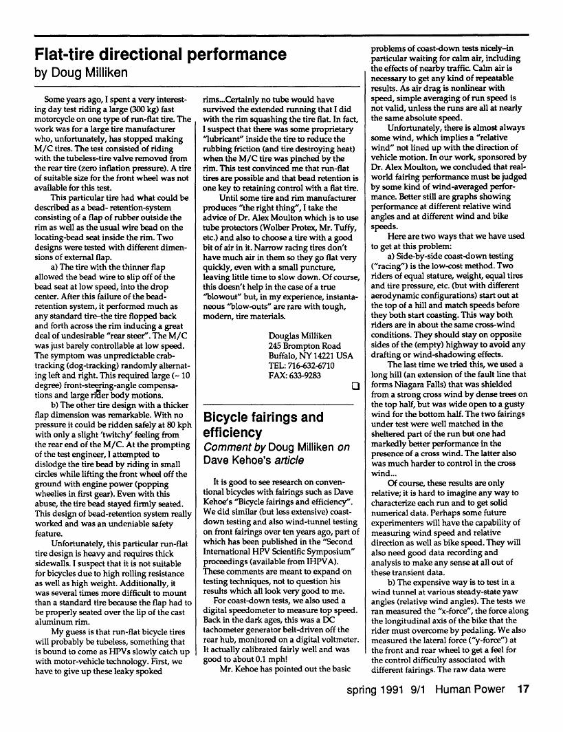
6) Make bearings, connecting rods andpedals.
Teflon and nylon and other plasticbearings are used (see figure 11).Consider well-oiled wood bearings. The
spring 1991 9/1 Human Power 11
-- - -.: I i -- lb-c~- i l l
L~ ._ _F IU Ji . _V_ i -- -_ _ i 1 t_ I _ ___
_~~~~_ __ L - __ __ rH;L---+1. -- ~-T-l · Lt-~-- -
I Mf nk I-~~~~; _1 __ J ?"I -~- - ·-- ·- --
! -i -1 - I V I·--rl I 7---
. - I--Y
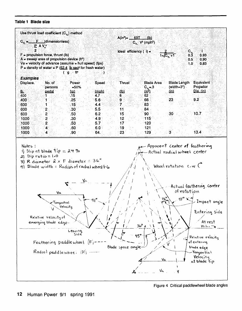
Table 1 Blade size
UI f' 'H... f, t( hs ust load coeoficient( ) method: .... . . ......
F..... ...... inre trs (b ffcecy()= .... 09sweep are.ofprpulio device....... 0.3..* Va -vlocity o advanc (assu..hul spe..d)....s) 1 . . .83 ......... den.t ofw trP.. h o fehw tr
400~~~~~~~. .. 1 .15.4.7.6 62400 1 ~~~~~. . 25 ....... ... ...6.9.. 66 23. 9..2
600 1 .15 4~~~~~~~~~.. .4...... . 7... ....3...
600 2 .50 6.2 15 90 30 107~~~~~~~~~~cie2:100 2...... . .30. 4.9 12 115yq
1000 4 .60 6~~~~~~~.. .0 19. 121. ....1000p~ 4 c9064 23ru 129b)3 1. 3.
Note' 5 Sh ip at b ~acke ?= 9L. 0/
'Di toatfo = 0 -SD(
R CkkO.Vne~er 9 x F \NICkTcr iS Ic'cl
OI~CAC
/f_ ppcareYt cerr tf~ -feherw"j. /ActIC4 r6Ld'llt wbeeA ceerc
/I, \./),; \', ... I ._ L_ _ . r / ~
I " Wne. VOTTiO" C.' AI ~
//
'I/
FecL*e icq pciacde IAAee~51Iloe space av'
/
/
Figure 4 Critical paddlewheel blade angles
12 Human Power 9/1 spring 1991
3)- . .. 1. - . . - f . . - . -
I
/
I
Ra'AICII PaAdlewhee_',
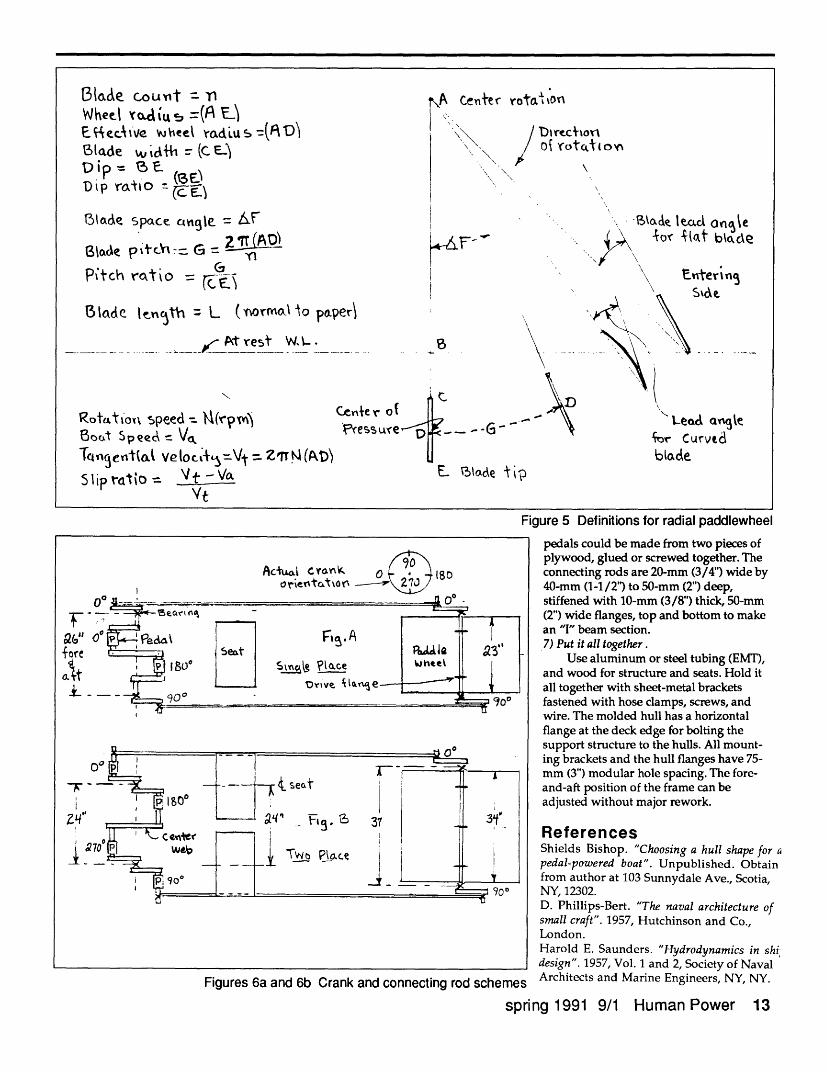
3lade cout nWheel ad id t =(A E)E CAedfve Vheel radiu s -(R DABlade ,ih == (Ce
Dip rato =--
Stlade space c ie -= e F
GLWe pt -c -- G =?
Pitch ratio = G
Bladec lenrth L (orroa to paper\
.... __. .. ..... At rest WL .
ROtaltioyx speed = Wl(rpmA Ce"+eBot Spee -= V F
Tncentiak veloc+L=Vt -= ZiTW(At))
S liprdtio = V - V\/t
\A Center rota: o'n
Diruc(otoAof Yrt(,J(0,A
-V.-ade t eac ang\e
-0,( #%et bide
EnteringSv 0
AB
r of
sure·f$ G -G -
E ltade ip
yl
NDk
A\
K.Leadc ange
Figure 5 Definitions for radial paddlewheel
Actuci CYankr
Va"
foreaptk-
iFIZqi
I
900 J (so
Fioures 6a and 6b Crank and connectina rod scheme
pedals could be made from two pieces ofplywood, glued or screwed together. Theconnecting rods are 20-mm (3/4") wide by40-mm (1-1/2') to 50-mm (2") deep,stiffened with 10-mm (3/8") thick, 50-mm(2") wide flanges, top and bottom to makean "I" beam section.7) Put it all together.
Use aluminum or steel tubing (EMT),and wood for structure and seats. Hold itall together with sheet-metal bracketsfastened with hose clamps, screws, andwire. The molded hull has a horizontalflange at the deck edge for bolting thesupport structure to the hulls. All mount-ing brackets and the hull flanges have 75-mm (3") modular hole spacing. The fore-and-aft position of the frame can beadjusted without major rework.
ReferencesShields Bishop. "Choosing a hull shape for apedal-powered boat". Unpublished. Obtainfrom author at 103 Sunnydale Ave., Scotia,NY, 12302.D. Phillips-Bert. "The naval architecture ofsmall craft". 1957, Hutchinson and Co.,London.Harold E. Saunders. "Hydrodynamics in shidesign". 1957, Vol. 1 and 2, Society of Naval
s Architects and Marine Engineers, NY, NY.
spring 1991 9/1 Human Power 13
f-r Curvt.1
I1
,\ ,
\\
I
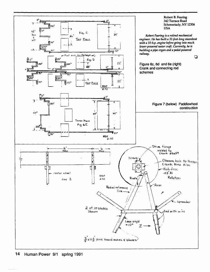
Robert B. Fearing342 Terrace RoadSchenectady, NY 12306USA
Robert Fearing is a retired mechanicalengineer. He has built a 32-foot-long steamboatwith a 10-h.p. engine before going into muchlower-powered water craft. Currently, he isbuilding a pipe organ and a pedal-poweredrailway.
Figure 6c, 6d and 6e (right)Crank and connecting rodschemes
Figure 7 (below) Paddlewheelconstruction
to hreacidkisc
reaer
Ace
y3 xi pine bioavlmrd o-M blade)
14 Human Power 9/1 spring 1991
U
CdT
7
w,
I'I
center whee
Z.elJ Z
a of toShow-
_
LO
;Z.c
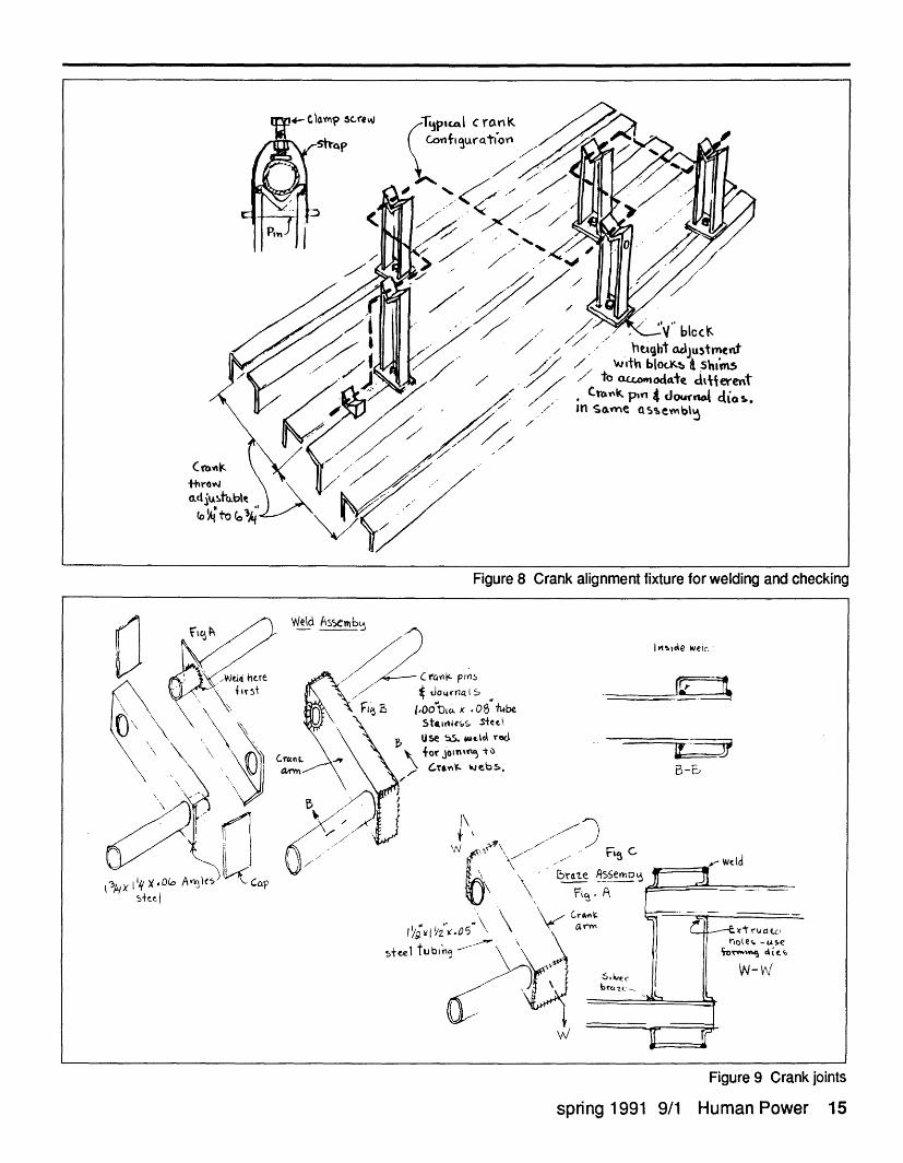
Figure 8 Crank alignment fixture for welding and checking
Figure 9 Crank joints
9/1 Human Power 15
- / t' .•V" blcc/ herght aoju5tmen.t
/ 7' SeDith blocKJ stain7 / to modat dtferent
/ Cros p 4 do-urnj d4is./ SLe ase5%bl
'fct, pnsJor nalt
tob, x .06 ibeitonrss ste Ise bS. wtka r&for joJn~r1 +o
cranr eb s. -E,
Fi C I
%
steel
st+e
spring 1991
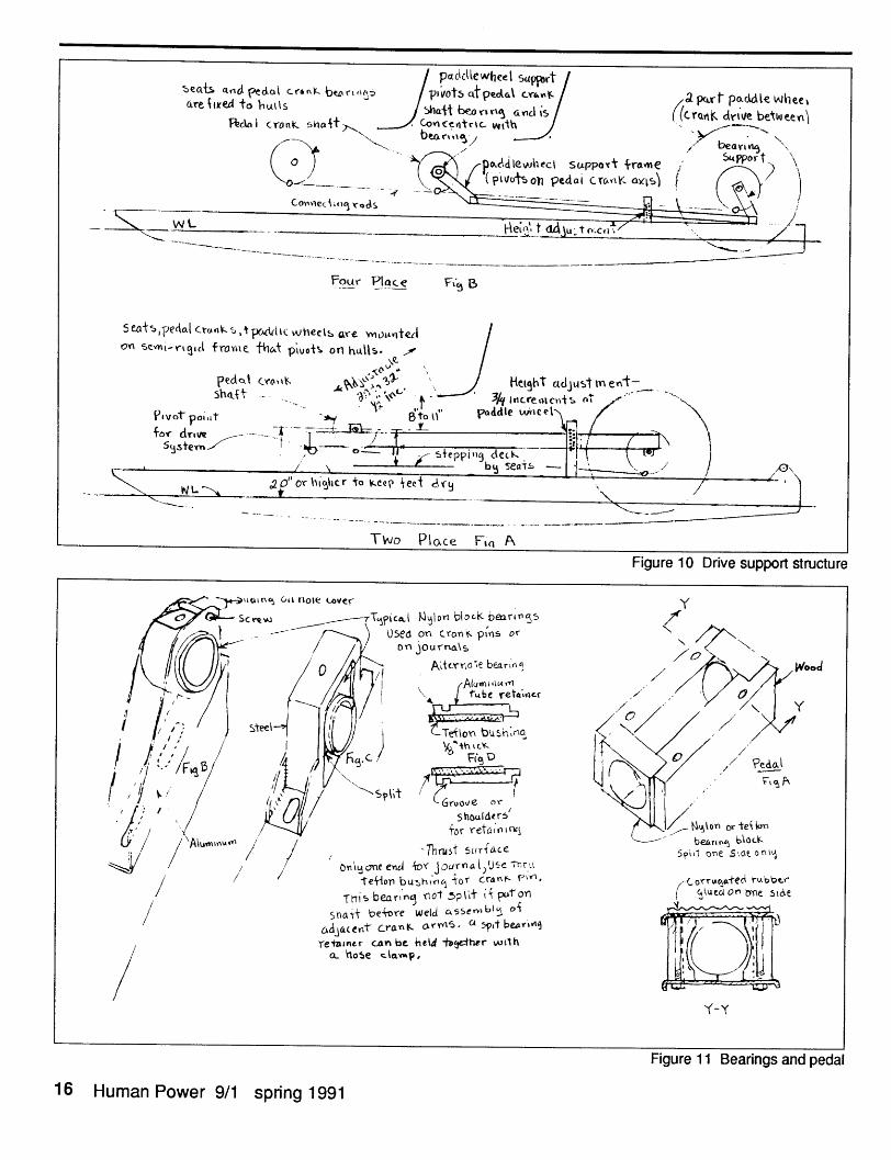
/ pcclewheel supPbrt /eab d eda ctnk be /lvots ctped\ tA a ptpadle wee(rt lved to hulls thaj be6orie ctol is/ ((crak. driv e between
Pedoi cronK shaft> Co ict r e Vith , er
o Y o/ P^UldleWIbei suppovt ramne Su pport1o P\ Ocd Leotsc pedai cr~ss au)ss
W __ , Wlecllt ad. u to.cl
Four Place Fi B
OaSe, edal ctfnr e ,t TpcMtiC hels ore o vnoa.teloYn sem-rigll fros that piuo.ts on htls-. e /
pdat Cuo~\ksha t
Pievot polat fov dre -- T -
Sdsten ,
* ' , /' \_
NL -2 0" Or higSl.. _ . . .- 1,-.
Two PioLce Fi A
Figure 10 Drive support structure
Figure 11 Bearings and pedal
16 Human Power 9/1 spring 1991
Y?icoA Mon block berirSs Used on c(on, ptns or
On journa\5
A''crnle barn
Alumn ,~maru tbe ret;cr
-Teflon bushlna
FiB D
shoulde rsfor retal2,n1
'I hrus1 Sutrace
encIl i'( JournaL)lUCe tr.It] - t. r rnr fLU!', IJ
Tnis bearig not plt i puon ( \uc4 ne sOaeShtat be-ore weld csserbl of
cadjalent cranK arya, a 5at bexrL9 IJ1retainer can be held -ty-ther wvth
a 0o5e clta.p,
Y-Y
wood
Flat-tire directional performanceby Doug Milliken
Some years ago, I spent a very interest-ing day test riding a large (300 kg) fastmotorcycle on one type of run-flat tire. Thework was for a large tire manufacturerwho, unfortunately, has stopped makingM/C tires. The test consisted of ridingwith the tubeless-tire valve removed fromthe rear tire (zero inflation pressure). A tireof suitable size for the front wheel was notavailable for this test.
This particular tire had what could bedescribed as a bead- retention-systemconsisting of a flap of rubber outside therim as well as the usual wire bead on thelocating-bead seat inside the rim. Twodesigns were tested with different dimen-sions of external flap.
a) The tire with the thinner flapallowed the bead wire to slip off of thebead seat at low speed, into the dropcenter. After this failure of the bead-retention system, it performed much asany standard tire-the tire flopped backand forth across the rim inducing a greatdeal of undesirable "rear steer". The M/Cwas just barely controllable at low speed.The symptom was unpredictable crab-tracking (dog-tracking) randomly alternat-ing left and right. This required large (- 10degree) front-steering-angle compensa-tions and large nrier body motions.
b) The other tire design with a thickerflap dimension was remarkable. With nopressure it could be ridden safely at 80 kphwith only a slight 'twitchy' feeling fromthe rear end of the M/C. At the promptingof the test engineer, I attempted todislodge the tire bead by riding in smallcircles while lifting the front wheel off theground with engine power (poppingwheelies in first gear). Even with thisabuse, the tire bead stayed firmly seated.This design of bead-retention system reallyworked and was an undeniable safetyfeature.
Unfortunately, this particular run-flattire design is heavy and requires thicksidewalls. I suspect that it is not suitablefor bicycles due to high rolling resistanceas well as high weight. Additionally, itwas several times more difficult to mountthan a standard tire because the flap had tobe properly seated over the lip of the castaluminum rim.
My guess is that run-flat bicycle tireswill probably be tubeless, something thatis bound to come as HPVs slowly catch upwith motor-vehicle technology. First, wehave to give up these leaky spoked
rims...Certainly no tube would havesurvived the extended running that I didwith the rim squashing the tire flat. In fact,I suspect that there was some proprietary"lubricant" inside the tire to reduce therubbing friction (and tire destroying heat)when the M/C tire was pinched by therim. This test convinced me that run-flattires are possible and that bead retention isone key to retaining control with a flat tire.
Until some tire and rim manufacturerproduces "the right thing", I take theadvice of Dr. Alex Moulton which is to usetube protectors (Wolber Protex, Mr. Tuffy,etc.) and also to choose a tire with a goodbit of air in it. Narrow racing tires don'thave much air in them so they go flat veryquickly, even with a small puncture,leaving little time to slow down. Of course,this doesn't help in the case of a true"blowout" but, in my experience, instanta-neous "blow-outs" are rare with tough,modern, tire materials.
Douglas Milliken245 Brompton RoadBuffalo, NY 14221 USATEL: 716-632-6710FAX: 633-9283
Bicycle fairings andefficiencyComment by Doug Milliken onDave Kehoe's article
It is good to see research on conven-tional bicycles with fairings such as DaveKehoe's "Bicycle fairings and efficiency".We did similar (but less extensive) coast-down testing and also wind-tunnel testingon front fairings over ten years ago, part ofwhich has been published in the "SecondInternational HPV Scientific Symposium"proceedings (available from IHPVA).These comments are meant to expand ontesting techniques, not to question hisresults which all look very good to me.
For coast-down tests, we also used adigital speedometer to measure top speed.Back in the dark ages, this was a DCtachometer generator belt-driven off therear hub, monitored on a digital voltmeter.It actually calibrated fairly well and wasgood to about 0.1 mph!
Mr. Kehoe has pointed out the basic
problems of coast-down tests nicely-inparticular waiting for calm air, includingthe effects of nearby traffic. Calm air isnecessary to get any kind of repeatableresults. As air drag is nonlinear withspeed, simple averaging of run speed isnot valid, unless the runs are all at nearlythe same absolute speed.
Unfortunately, there is almost alwayssome wind, which implies a "relativewind" not lined up with the direction ofvehicle motion. In our work, sponsored byDr. Alex Moulton, we concluded that real-world fairing performance must be judgedby some kind of wind-averaged perfor-mance. Better still are graphs showingperformance at different relative windangles and at different wind and bikespeeds.
Here are two ways that we have usedto get at this problem:
a) Side-by-side coast-down testing("racing") is the low-cost method. Tworiders of equal stature, weight, equal tiresand tire pressure, etc. (but with differentaerodynamic configurations) start out atthe top of a hill and match speeds beforethey both start coasting. This way bothriders are in about the same cross-windconditions. They should stay on oppositesides of the (empty) highway to avoid anydrafting or wind-shadowing effects.
The last time we tried this, we used along hill (an extension of the fault line thatforms Niagara Falls) that was shieldedfrom a strong cross wind by dense trees onthe top half, but was wide open to a gustywind for the bottom half. The two fairingsunder test were well matched in thesheltered part of the run but one hadmarkedly better performance in thepresence of a cross wind. The latter alsowas much harder to control in the crosswind...
Of course, these results are onlyrelative; it is hard to imagine any way tocharacterize each run and to get solidnumerical data. Perhaps some futureexperimenters will have the capability ofmeasuring wind speed and relativedirection as well as bike speed. They willalso need good data recording andanalysis to make any sense at all out ofthese transient data.
b) The expensive way is to test in awind tunnel at various steady-state yawangles (relativp wind angles). The tests weran measured the "x-force", the force alongthe longitudinal axis of the bike that therider must overcome by pedaling. We alsomeasured the lateral force ("y-force") atthe front and rear wheel to get a feel forthe control difficulty associated withdifferent fairings. The raw data were
spring 1991 9/1 Human Power 17
corrected to a standard velocity anddensity condition and plotted as "x-force"vs. yaw angle.
From the basic data it is possible tomake plots of "x-force" drag for combina-tions of different bike speeds, windspeeds and wind directions. We crossplotted the raw data on polar paper andthe plot we came up with is somewhatsimilar to the "velocity-made-good" plotused to characterize sailboats withdifferent sails, in different wind condi-tions.
The wind tunnel is a powerful tool.Until some future date when we canafford to truly calculate entire flow fieldsby super-super-computer, the windtunnel is still the only way to reallymeasure the stalled-flow aerodynamics ofbluff bodies, such as partially streamlinedbicycles. There is also a lot to be said forthe experience of sitting on a bike in awind tunnel in the absence of otherdistractions. In particular, I found that Ibecame very sensitive to any little bit offlapping clothing-by tightening variousmuscles or shifting slightly I could stopthe flapping and reduce my drag (notethat our tests were just at the dawn of skinsuits).
Incidentally, the upright, fully faired,Alex Moulton 51-mph (23-m/s) runmentioned at the beginning of the articlewas made by Jim Glover in a fairingdesigned and built by me, not ZZipDesigns. The confusion is easy to under-stand because ZZip make a special modelroad fairing to fit the AM Bicycle. The200-meter run in question was at the 12thIHPSC in Vancouver, Canada, at sea level,and on near-level ground. In all fairness,this should not be directly compared toruns made at high altitude, on a coursewith IHPVA-legal down-hill slope.
The bike inside the "Moulton-Milliken 'Liner II" was a predecessor ofthe AM "Jubilee" model, now in produc-tion in England. With continuing supportfrom Alex Moulton Bicycles Ltd., thecurrent-generation "M-M 'Liner III" hasshown good results, especially in Hull1989 (Jim Glover riding) and Milwaukee1990 (with Fred Markham up). Timedruns to date have been plagued by poorwind conditions. 'Liner III is based on thenew AM "Speed" model: look for us atthe IHPSC this summer in Milwaukee!
Douglas Milliken245 Brompton RoadBuffalo, NY 14221 USATEL: 716-632-6710FAX: 633-9283
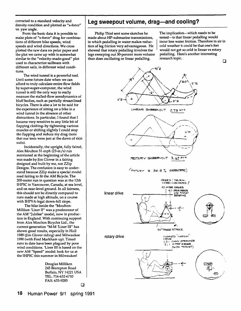
Leg sweepout volume, drag-and cooling?
Philip Thiel sent some sketches hemade about HP-submarine transmissions,in which pedalling in water makes reduc-tion of leg friction very advantageous. Heshowed that rotary pedalling involves thelegs sweeping out 30-percent more volumethan does oscillating or linear pedalling.
The implication-which needs to betested-is that linear pedalling wouldincur less water friction. Therefore in air incold weather it could be that one's feetwould not get so cold in linear vs rotarypedalling. Here's another interestingresearch topic. In
LUEA2r 95 -C'UT 2.79 ri
rea~y 'y S&EM-Cu , r 3, ' H
oe 4 - 9ELutRe(,IkAT- LU.1CA.E TV
4:1 ITE aes4:1 S R eS
lin r drin LA NES(0- ? I UP1rJG
O I
X X
rotary drive\ ,
VC~vEPi ADS\ Ht19sLD,21VG,
(WIM TRwUST
(( - I = - E(I V,~ C5~J~~( F.,~~~~~~~~~~~~~~~~~~~~
18 Human Power 9/1 spring 1991
r 'I
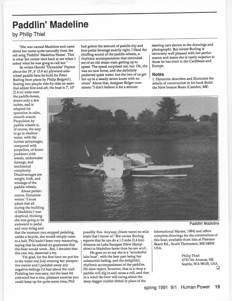
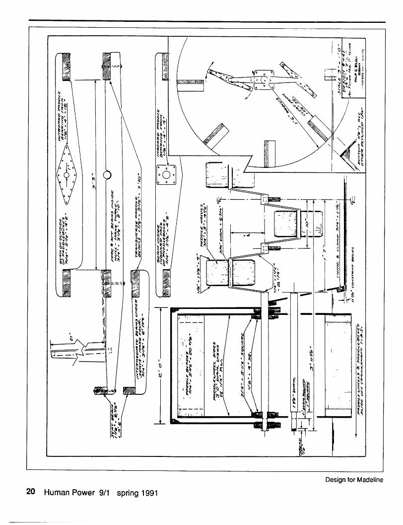
Design for Madeline
20 Human Power 9/1 spring 1991
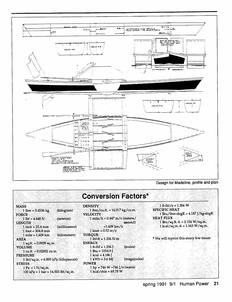
Design for Madeline, profile and plan........... . ....... . .... ....
.. .. ........ ..... . ........ I.... .. .. ........... ....... .... .. .... ...... ... ... ....... .. ........ . ........ .. .. ......... .. ..... ........ ... ...... ...... .. ...... . ............. onversion F". . .. ......... ..... .... .. .. ............ .... . .......... ... ................... ac o rs. .. .. ................ .. .... ... . .......... .......... ...... ... .. .. ............ ..........
................ ............ . ......... ft-lbf/s :1356 W.......... ..... ..... ... ..... ........MASS: DENSM + . .... .... ........... . .. ... . .... . .. ... ... . .... ..r11 ..... .in 0.4536'k .. .. .. (kil lb V A 1 6.01 7 k ̀ h' SPECIFIC HEAT1101kC ... ... ......... /lb egR �deg +.. ........... - .... .. .. .......... . �d + .1 J / k........... tu.... ..... .......... ...xELOCITY 4 K..... .. ............ .............. .. .. .... .. ... ........... .. ......... .. ...... .......11bb ":'4.+448:N::::: ne won jfnil61h: 0.447 +- AT FLUX
.. . . . . . . .. . ..... . .. ........... . ..... . . ........I Bb ft.-h 3... ...... . ........ ....... . ..... ......... ... ... n ... .. ........... ...... . . ...... . . ........ ........ .. ............ .... .. . . ...... I.. . ...... ............ .. 1 4 W /. . . . . . . .......... U sq. ........W ... . . .. M M ..W . . I . ......... .. ..... .. ... ....... . .............. ..... .................... ......
mm ....... 1': 609w:kfi/h'. -h 1.163 W/. .. .. .. ... ..... ..J. :i+ ::':':"2 5 4 .. ...... ...... . sq.... .......... ..... ...V4.8: khbt .52........ M M ...... ....... ....................X:11 609 ()UIO rfi, O"' Os Tortotit:..... . sues. ............ ....... ......... ...... .....
. . . .... . ........ i s........ ............. will repnnt t is everARE .......... lbf;�wft: 1��56 N y f6......... . .. .. .. . ........ .. .. ............ ..... . ....... . .... .....ENERGY G.. ........... e sO LU M E . '' ' "W .' .,+. I-..mm M v+.+v +V%-. ... ...M' + +M. +.M� .+.+ W+. .: :1 ft 4 bf: 1 3 56'1 iW. ... .. ......... .. .. ........
cu 02832 cu Btu 1 054.9PRESSURE +... M 4.1 86' 1
-6 89 5 kPa (kild Is) :16 MJ . egaJoules,lbf /sd A n . pasca . . .. .. ..... .....
STRESS.. POWER .......:+- :1 NA q- 1h 746 W446 JAwatt +)++J: PA: F� ..... .. ....... .. .. ..000 ar c rru n ......Ib 14.503 1bf/ s+ Jn. Ik 9/ 69'78 W++
... . . . ....... ... .... ... ... .. . . ... ..... .... .. ....... ... ........... . ........ .... ...... . ..... ... .. ....... ............... .. .. ...... ...
spnng 1991 9/1 Human Power 21
..... I..... ~~~~~~~~~~~~~~~~~~~~~~~~~- I
..'-I- /I - -, " i
,/ I II 1 . - /T7 ! -iI. '
I ,mz~ .._ / , - ' .. s
'¾ V~
7
71
P.4
' - tr- ..... 1. '
I ..7 H /~~~~~~~~~~~~~~~~~~t
.,//
J..:j--
11
J
-
- � 7 7 7- -
I..II
-- i '1- ----
1991 Royal Aeronautical SocietyHuman-Powered Flight Conference, January 30, 1991Chris Roper, VP-Air
As at such conferences in previousyears, those interested in HPF from manycountries met and heard a fascinatingarray of speakers. Chairman Frank Lowallowed ample time for discussion.
No prizes were awarded this year: theKremer Seaplane competition and theKremer Marathon competition remainopen.
John McIntyre of Cambridge,England, gave an account of his Airglowplane which first flew last July. Designedin 1986/7, this aircraft is similar toDaedalus in many ways. Construction hasbeen almost entirely within the McIntyrehousehold by John and his brother Mark.This has included first making the equip-ment to produce carbon-fibre tubes for thespars and the manufacture of a gearbox.The team had access to a CambridgeUniversity computer and help from Ciba-Geigy and other local firms.
A development is the use of a fly-by-wire control system. Model-aircraft servosare mounted next to the control surfaces,and wires lead between these and thepilot's column.
John said that his design philosophyhas been to err on the side of making anycomponent slightly heavier if this will givean aerodynamic advantage. The fuselageframe is very robust to provide stiffnessfor the transmission, and for pilot safety.
Flight tests so far have shown that thelength of the runway at Duxford iscovered easily. Pilot Nick Weston statesthat take-off is quite hard work though;this is blamed on the high rolling resis-tance of the wheel chosen, a standardglider wheel. With regard to ground crew,McIntyre recommends a launch-team anda separate chase-and-retrieve team. Biggestproblem is water-vapor condensation onthe wings in the early morning when mostflights are made.
Peter Wray of Loughborough Univer-sity told us about the HPA project that isunderway there and which started, hesaid, at the equivalent RAeS conferencetwo years ago.
This group's constraints are that workmust be dovetailed into academic studies,and that the first aircraft must fly in orderto get continued support.
Pictures of the oven for carbon-fibretubes showed it to be a copy of JohnMcIntyre's twin-box-and-blower design,but upgraded to industrial safety stan-
dards. This university team's digital foam-cutter is on the principle of that used atMIT, but the wire-holders are not justgraph-plotters: they have been engineeredfrom scratch for their purposes.
Wayne Bleisner was expected, but hisfamily had persuaded him not to fly toBritain for fear of reprisals against the USand UK during the Iraq/Kuwait war.However, his paper was read, and weheard of his Marathon Eagle project, theonly known direct attempt for the KremerMarathon prize.
This will have a retractable undercar-riage and "rudder" at the back of the podin addition to a rudder in the usual place.This may "give" when flying with sideslip,or perhaps be active and "push".
The wing-structure will be a carbon-box spar 50mm square at the root, with amonocoque sandwich skin.
Much computer analysis of wing-fuselage interference has led to an unusualplanform at the root.
Peter Selinger of the German HVSteam described this project. The "H" is forHutte, glider designer; the "V" for FrankVillinger, who was responsible withHelmut Haessler for the Mufli of 1935.First sketch for the HVS was in 1975, anddesign was revised in 1978.
Selinger admitted that this project hadnot been a success. These grandfathers ofHPF had built a machine which exces-sively copied glider principles. The controlsystem alone, while beautifully con-structed, must have weighed more thanthe transmission on some HPAs. The wingwas all-molded monocoque and was aperfect shape: later, to try to save weight,the team cut holes in it which they coveredwith plastic film. Treadle-movementpedals drove the variable-pitch propellerand a spool-drive to the ground-wheel.Rigging procedure involved the pilotbeing seated first, then the wing wasadded on top.
The first flight was in June 1982(wrongly quoted elsewhere), and flights ofup to 700 [m]? were made. In 1985 thegroup disbanded, and the plane nowshines down from its perch in a museum.
Peer Frank, now living and workingin Virginia, USA, told us of flight tests andpre-flight tests in Germany of his Velair.
For the fliaht-tets_ he develnned an 8-channel data logger that was adaptable formany tasks. It recorded pilot heart-rate,
prop-revs, control deflection, cabintemperature, stress in the spar and otherparameters. This quantitative informationwas compared with the subjective assess-ment of the pilot, for instance, that flyingin gusty conditions is much harder work.
On the ground an attempt had beenmade to test the propeller by mounting iton the roof of a car. So far, these tests havebeen of limited value, since vibration hascaused wide scatter in the measurementsof thrust.
Other tests have included a proof-testof the spar with deflection-vs-loadrecorded, and fully-instrumented ergome-ter tests with four human aero-engines.
The Velair programme is temporarilyshelved since "the experience is now beingapplied to the development of a very-high-altitude research airplane."
Chris Roper, V-P for Air19 Stirling Court29 Tavistock StreetCovent Garden, LondonWC2E 7NUUNITED KINGDOM
Chris Roper is a pioneer in and anenthusiast for HP aircraft, having finished hisfirst design in 1961 (the "Hodgess Roper").He, and many volunteers, started the construc-tion of his second design, Jupiter, in 1963. (Healso married one of the volunteers, SusanJones). The plane flew many times in 1972.One flight was a then-record distance, 1070 m.Chris has just finished the MS of a book aboutHP flight, giving technical details andcomments on every known flight attempt; weare anxious to see it published, and Chris has
_!___~~~ ·_ _ _ l __: , a_.L _ _ :. lrn
given us permission to puotlsn extracts n at'.We are delighted to have such a knowledgeableenthusiast as VP-Air.
22 Human Power 9/1 spring 1991
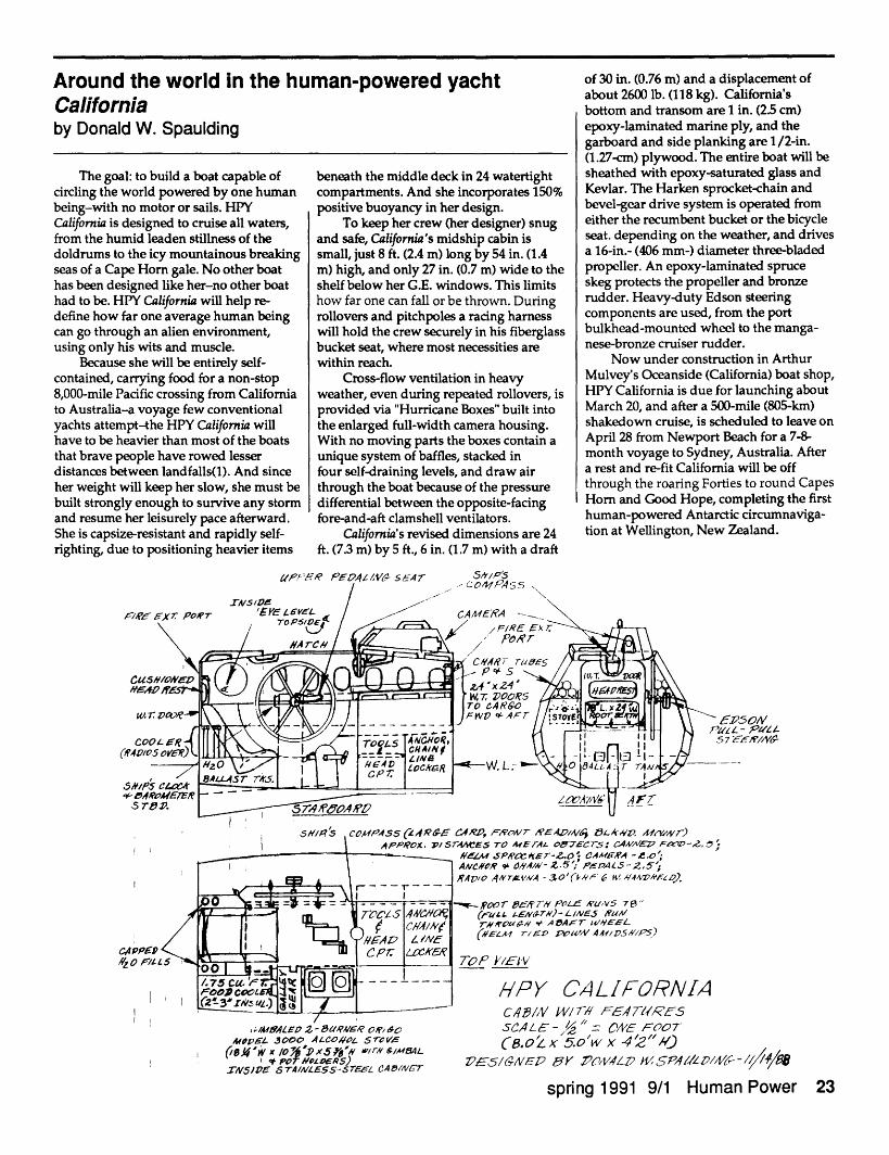
Around the world in the human-powered yachtCaliforniaby Donald W. Spaulding
The goal: to build a boat capable ofcircling the world powered by one humanbeing-with no motor or sails. HPYCalifornia is designed to cruise all waters,from the humid leaden stillness of thedoldrums to the icy mountainous breakingseas of a Cape Horn gale. No other boathas been designed like her-no other boathad to be. HPY California will help re-define how far one average human beingcan go through an alien environment,using only his wits and muscle.
Because she will be entirely self-contained, carrying food for a non-stop8,000-mile Pacific crossing from Californiato Australia-a voyage few conventionalyachts attempt-the HPY California willhave to be heavier than most of the boatsthat brave people have rowed lesserdistances between landfalls(l). And sinceher weight will keep her slow, she must bebuilt strongly enough to survive any stormand resume her leisurely pace afterward.She is capsize-resistant and rapidly self-righting, due to positioning heavier items
beneath the middle deck in 24 watertightcompartments. And she incorporates 150%positive buoyancy in her design.
To keep her crew (her designer) snugand safe, California's midship cabin issmall, just 8 ft. (2.4 m) long by 54 in. (1.4m) high, and only 27 in. (0.7 m) wide to theshelf below her G.E. windows. This limitshow far one can fall or be thrown. Duringrollovers and pitchpoles a racing harnesswill hold the crew securely in his fiberglassbucket seat, where most necessities arewithin reach.
Cross-flow ventilation in heavyweather, even during repeated rollovers, isprovided via "Hurricane Boxes" built intothe enlarged full-width camera housing.With no moving parts the boxes contain aunique system of baffles, stacked infour self-draining levels, and draw airthrough the boat because of the pressuredifferential between the opposite-facingfore-and-aft clamshell ventilators.
California's revised dimensions are 24ft. (7.3 m) by 5 ft., 6 in. (1.7 m) with a draft
of 30 in. (0.76 m) and a displacement ofabout 2600 lb. (118 kg). California'sbottom and transom are 1 in. (25 cm)epoxy-laminated marine ply, and thegarboard and side planking are 1/2-in.(1.27-cm) plywood. The entire boat will besheathed with epoxy-saturated glass andKevlar. The Harken sprocket-chain andbevel-gear drive system is operated fromeither the recumbent bucket or the bicycleseat. depending on the weather, and drivesa 16-in.- (406 mm-) diameter three-bladedpropeller. An epoxy-laminated spruceskeg protects the propeller and bronzerudder. Heavy-duty Edson steeringcomponents are used, from the portbulkhead-mounted wheel to the manga-nese-bronze cruiser rudder.
Now under construction in ArthurMulvey's Oceanside (California) boat shop,HPY California is due for launching aboutMarch 20, and after a 500-mile (805-km)shakedown cruise, is scheduled to leave onApril 28 from Newport Beach for a 7-8-month voyage to Sydney, Australia. Aftera rest and re-fit California will be offthrough the roaring Forties to round CapesHorn and Good Hope, completing the firsthuman-powered Antarctic circumnaviga-tion at Wellington, New Zealand.
aP,%: A PF41A/V,- SEAr S5/PS,.,l,<,
.'Aql, 'q; r/'"/,Pd A /2z IARt _,.x.._ N- ,4 .F.N, R AD, 9_ ., A-. ... NA/)
~~~~I X;IMArLO 2- lEIP8/V~ O/BO
MOPf n 3o000 ALCozo-L 5 rVo
I * POT NzfDRDE) 'A/NWIV51 pe 6T41"/AES-S-T C4AEA
sC4/ ' - "- N = FOTC8.oZ x 5.0'w x 4 ")
?--5/16ES/ 2D F5 9,7z' KSP,1a//LV/6- 1 -/ 4/1498
spring 1991 9/1 Human Power 23
44CAPPAZ O -//
ES To E rTA,4 0E76C : C4MVgi5 F2-.ZM 6P1aze kr- . CAAI6'A -e .o'#0,R 9 ,14A/1- Z 5Ir PK 5ALS5-2,51/o ,4,VTVA - 3 O'(f '/ 6 4kVEZ op
por 7S ai Poe_ 'U ,v 7 "('auz. zEN6~T5b-L/-NE5 7Al/
#-,rOx!H,v +. A0ACT IXEL
bsL, JnD ze W'4AAI /DVS; PoS)
P /EI'V
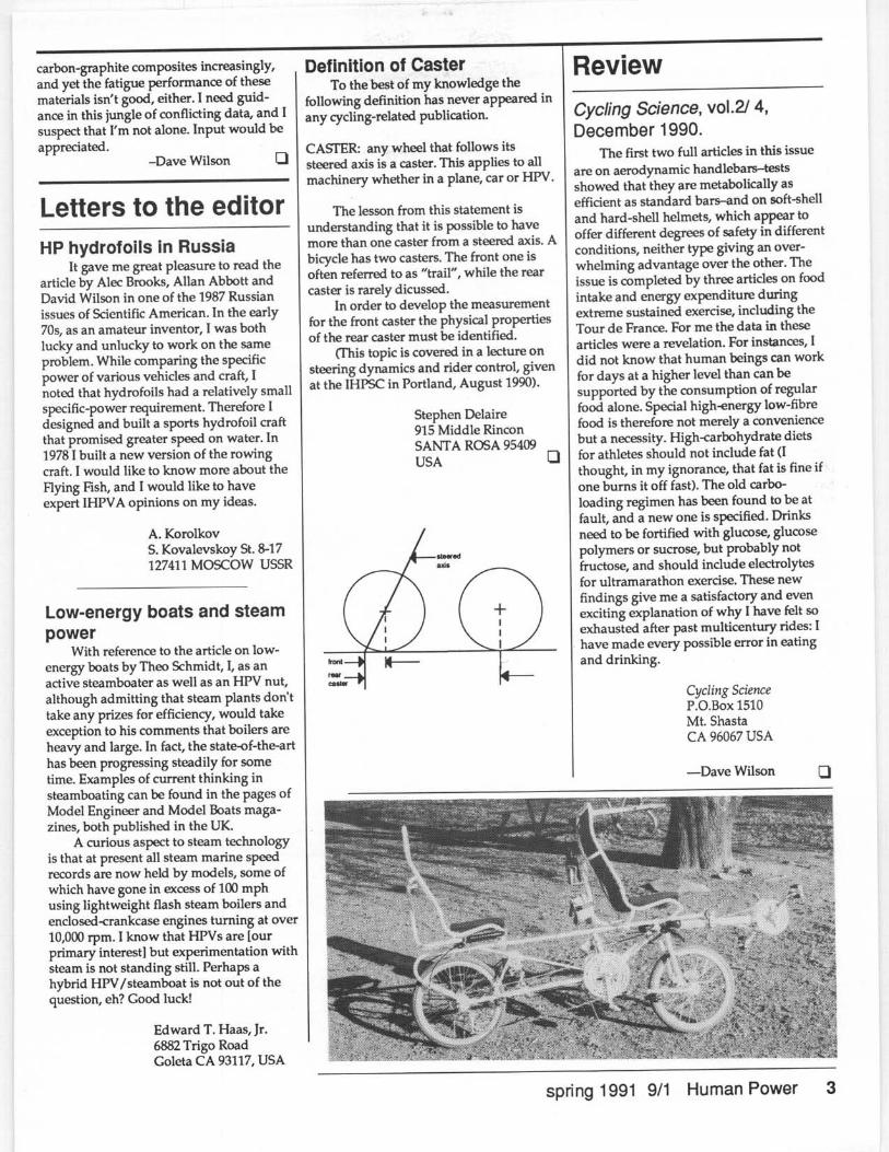
/HPY CALIFORNIAC4/,V W/7 Elr7lRE5I
/-CPEI Iet--- CAB/IV C P7. - - .BLW O SLA-W-. L.04.
DRFTD SPL.4PPRoX..SPeEEz-
22'6 "20"0 "5'0"2 '0"
2470Lb.C?ZE/SE
. 5-2.o K0s.A //1 /
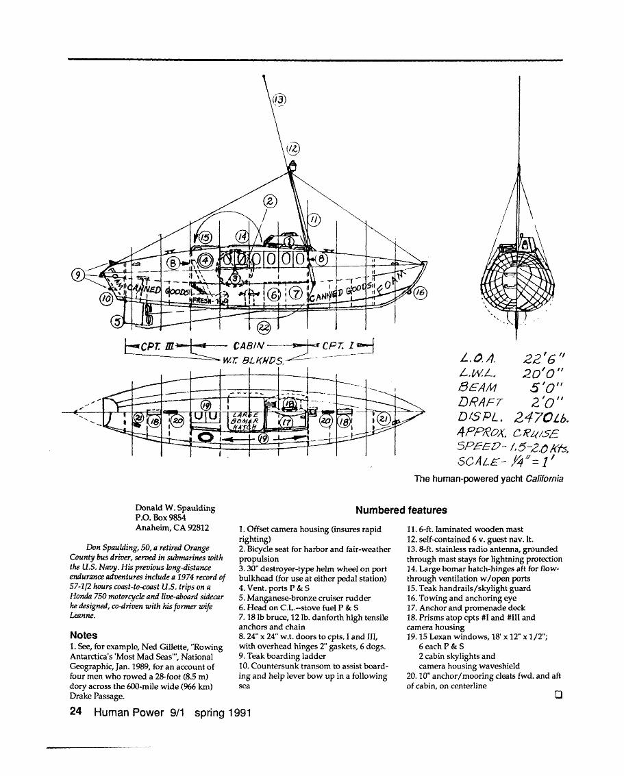
The human-powered yacht California
Donald W. SpauldingP.O. Box 9854Anaheim, CA 92812
Don Spaulding, 50, a retired OrangeCounty bus driver, served in submarines withthe U.S. Navy. His previous long-distanceendurance adventures include a 1974 record of57-112 hours coast-to-coast U.S. trips on aHonda 750 motorcycle and live-aboard sidecarhe designed, co-driven with his former wifeLeanne.
Notes1. See, for example, Ned Gillette, "RowingAntarctica's 'Most Mad Seas"', NationalGeographic, Jan. 1989, for an account offour men who rowed a 28-foot (8.5 m)dory across the 600-mile wide (966 km)Drake Passage.
Numbered features
1. Offset camera housing (insures rapidrighting)2. Bicycle seat for harbor and fair-weatherpropulsion3. 30" destroyer-type helm wheel on portbulkhead (for use at either pedal station)4. Vent. ports P & S5. Manganese-bronze cruiser rudder6. Head on C.L.-stove fuel P & S7. 18 lb bruce, 12 lb. danforth high tensileanchors and chain8. 24" x 24" w.t. doors to cpts. I and III,with overhead hinges 2" gaskets, 6 dogs.9. Teak boarding ladder10. Countersunk transom to assist board-ing and help lever bow up in a followingsea
11. 6-ft. laminated wooden mast12. self-contained 6 v. guest nav. It.13.8-ft. stainless radio antenna, groundedthrough mast stays for lightning protection14. Large bomar hatch-hinges aft for flow-through ventilation w/open ports15. Teak handrails/skylight guard16. Towing and anchoring eye17. Anchor and promenade deck18. Prisms atop cpts #I and #III andcamera housing19.15 Lexan windows, 18' x 12" x 1/2";
6 each P & S2 cabin skylights andcamera housing waveshield
20. 10" anchor/mooring cleats fwd. and aftof cabin, on centerline
24 Human Power 9/1 spring 1991