Embed Size (px)
Citation preview

7/16/2019 Edu Cat en v5a Fb v5r19
http://slidepdf.com/reader/full/edu-cat-en-v5a-fb-v5r19 1/172
CATIA V5 Analysis

7/16/2019 Edu Cat en v5a Fb v5r19
http://slidepdf.com/reader/full/edu-cat-en-v5a-fb-v5r19 2/172

7/16/2019 Edu Cat en v5a Fb v5r19
http://slidepdf.com/reader/full/edu-cat-en-v5a-fb-v5r19 3/172
CATIA V5 Analysis
STUDENT GUIDE
Copyright DASSAULT SYSTEMES 3
Student Handbook
Version 5 Release 19
CATIA V5 Analysis
16 Hours

7/16/2019 Edu Cat en v5a Fb v5r19
http://slidepdf.com/reader/full/edu-cat-en-v5a-fb-v5r19 4/172
CATIA V5 Analysis
STUDENT GUIDE
Copyright DASSAULT SYSTEMES 4
No part of this publication may be reproduced, translated, stored in retrieval system ortransmitted, in any form or by any means, including electronic, mechanical,photocopying, recording or otherwise, without the express prior written permission
of DASSAULT SYSTEMES. This courseware may only be used with explicitDASSAULT SYSTEMES agreement.
ALL RIGHTS RESERVED
Copyright DASSAULT SYSTEMES
7/16/2019 Edu Cat en v5a Fb v5r19
http://slidepdf.com/reader/full/edu-cat-en-v5a-fb-v5r19 5/172
CATIA V5 Analysis
STUDENT GUIDE
Copyright DASSAULT SYSTEMES 5
Table of Contents
Introduction to Finite Element Analysis 7
Pre-processing 37
Computation 63
Post-processing 81
Mesh Refinement 113
Assembly Structural Analysis 125
Master Project 138
Shortcuts 164
Glossary 165

7/16/2019 Edu Cat en v5a Fb v5r19
http://slidepdf.com/reader/full/edu-cat-en-v5a-fb-v5r19 6/172
7/16/2019 Edu Cat en v5a Fb v5r19
http://slidepdf.com/reader/full/edu-cat-en-v5a-fb-v5r19 7/172
CATIA V5 Analysis
STUDENT GUIDE
Copyright DASSAULT SYSTEMES 7
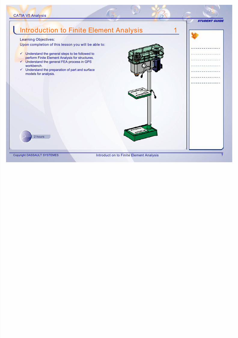
Introduction to Finite Element Analysis 1
9 Understand the general steps to be followed to
perform Finite Element Analysis for structures.9 Understand the general FEA process in GPSworkbench.
9 Understand the preparation of part and surfacemodels for analysis.
Learning Objectives:
Upon completion of this lesson you will be able to:
2 hours
Introduction to Finite Element Analysis
7/16/2019 Edu Cat en v5a Fb v5r19
http://slidepdf.com/reader/full/edu-cat-en-v5a-fb-v5r19 8/172
CATIA V5 Analysis
STUDENT GUIDE
Copyright DASSAULT SYSTEMES 8
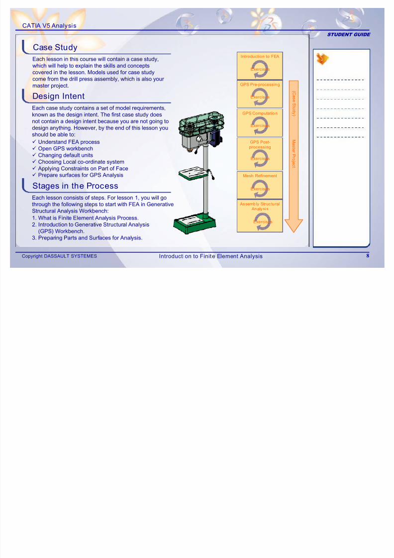
Each lesson in this course will contain a case study,which will help to explain the skills and conceptscovered in the lesson. Models used for case studycome from the drill press assembly, which is also yourmaster project.
Design Intent
Stages in the Process
Each case study contains a set of model requirements,known as the design intent. The first case study doesnot contain a design intent because you are not going todesign anything. However, by the end of this lesson youshould be able to:
9 Understand FEA process9 Open GPS workbench9 Changing default units9 Choosing Local co-ordinate system9 Applying Constraints on Part of Face9 Prepare surfaces for GPS Analysis
Each lesson consists of steps. For lesson 1, you will gothrough the following steps to start with FEA in GenerativeStructural Analysis Workbench:
1. What is Finite Element Analysis Process.2. Introduction to Generative Structural Analysis
(GPS) Workbench.3. Preparing Parts and Surfaces for Analysis.
Case Study
GPS Pre-processing
GPS Computation
GPS Post-
processing
Exercises
Exercises
Exercises
Introduction to FEA
Exercises
M a s t er P r o j e c t
( C
a s e S t u d y )
Mesh Refinement
Assemb ly Structural
Analysis
Exercises
Exercises
Introduction to Finite Element Analysis
7/16/2019 Edu Cat en v5a Fb v5r19
http://slidepdf.com/reader/full/edu-cat-en-v5a-fb-v5r19 9/172
CATIA V5 Analysis
STUDENT GUIDE
Copyright DASSAULT SYSTEMES 9
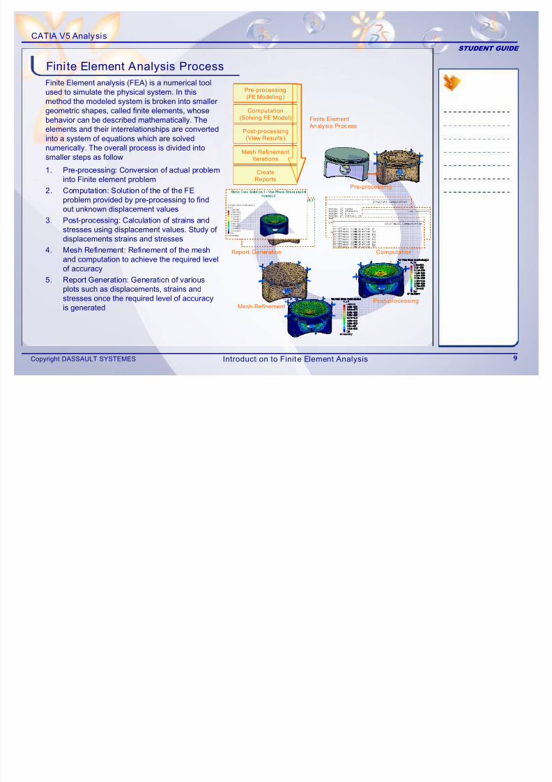
Finite Element analysis (FEA) is a numerical toolused to simulate the physical system. In thismethod the modeled system is broken into smallergeometric shapes, called finite elements, whosebehavior can be described mathematically. Theelements and their interrelationships are converted
into a system of equations which are solvednumerically. The overall process is divided intosmaller steps as follow
1. Pre-processing: Conversion of actual probleminto Finite element problem
2. Computation: Solution of the of the FEproblem provided by pre-processing to findout unknown displacement values
3. Post-processing: Calculation of strains andstresses using displacement values. Study of displacements strains and stresses
4. Mesh Refinement: Refinement of the meshand computation to achieve the required levelof accuracy
5. Report Generation: Generation of variousplots such as displacements, strains andstresses once the required level of accuracyis generated
Fini te Element Analysis Process
Finite Element
Analysis Process
Computation
(Solving FE Model)
Pre-processing
(FE Modeling)
Post-processing
(View Results )
Mesh Refinement
Iterations
Create
Reports
Pre-processing
Computation
Post-processingMesh-Refinement
Report Generation
Introduction to Finite Element Analysis
7/16/2019 Edu Cat en v5a Fb v5r19
http://slidepdf.com/reader/full/edu-cat-en-v5a-fb-v5r19 10/172
CATIA V5 Analysis
STUDENT GUIDE
Copyright DASSAULT SYSTEMES 10
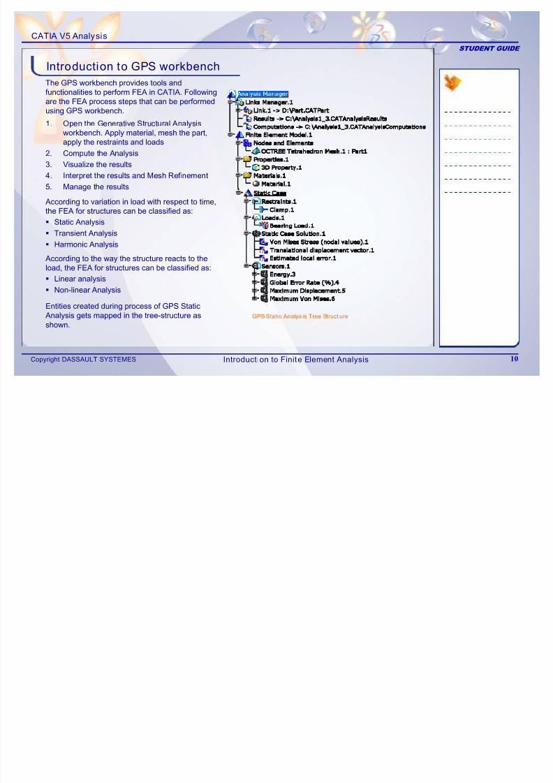
Introduction to GPS workbench The GPS workbench provides tools andfunctionalities to perform FEA in CATIA. Followingare the FEA process steps that can be performedusing GPS workbench.
1. Open the Generative Structural Analysisworkbench. Apply material, mesh the part,apply the restraints and loads
2. Compute the Analysis
3. Visualize the results
4. Interpret the results and Mesh Refinement
5. Manage the results
Entities created during process of GPS StaticAnalysis gets mapped in the tree-structure asshown.
GPS Static Analys is Tree Structure
Static Analysis
Transient Analysis
Harmonic Analysis
Linear analysis
Non-linear Analysis
According to variation in load with respect to time,the FEA for structures can be classified as:
According to the way the structure reacts to theload, the FEA for structures can be classified as:
Introduction to Finite Element Analysis
7/16/2019 Edu Cat en v5a Fb v5r19
http://slidepdf.com/reader/full/edu-cat-en-v5a-fb-v5r19 11/172
CATIA V5 Analysis
STUDENT GUIDE
Copyright DASSAULT SYSTEMES 11
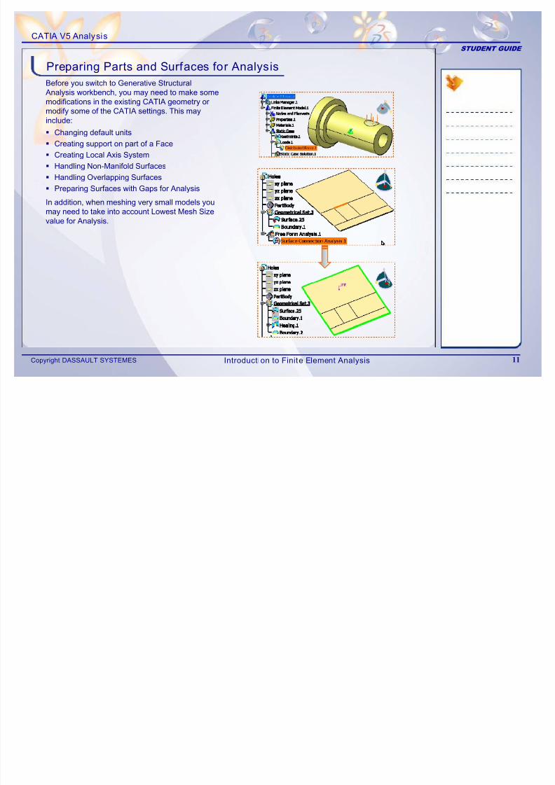
Preparing Parts and Surfaces for AnalysisBefore you switch to Generative StructuralAnalysis workbench, you may need to make somemodifications in the existing CATIA geometry ormodify some of the CATIA settings. This mayinclude:
Changing default units
Creating support on part of a Face
Creating Local Axis System
Handling Non-Manifold Surfaces
Handling Overlapping Surfaces
Preparing Surfaces with Gaps for Analysis
In addition, when meshing very small models youmay need to take into account Lowest Mesh Sizevalue for Analysis.
Introduction to Finite Element Analysis
7/16/2019 Edu Cat en v5a Fb v5r19
http://slidepdf.com/reader/full/edu-cat-en-v5a-fb-v5r19 12/172
CATIA V5 Analysis
STUDENT GUIDE
Copyright DASSAULT SYSTEMES 12
Tools Used for Preparing Parts and Surfaces for Analysis (1/2)
1
2
3
4
5
6
1
2
3
4
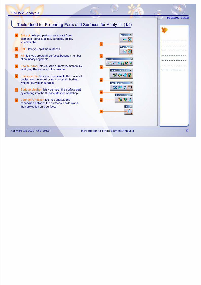
Extract: lets you perform an extract fromelements (curves, points, surfaces, solids,volumes etc).
Split: lets you split the surfaces.
Fill: lets you create fill surfaces between numberof boundary segments.
Sew Surface: lets you add or remove material bymodifying the surface of the volume.
Disassemble: lets you disassemble the multi-cellbodies into mono-cell or mono-domain bodies,whether curves or surfaces.
Surface Mesher: lets you mesh the surface partby entering into the Surface Mesher workshop.
Connect Checker: lets you analyze theconnection between the surfaces’ borders andtheir projection on a surface.
5
6
7
7
Introduction to Finite Element Analysis
7/16/2019 Edu Cat en v5a Fb v5r19
http://slidepdf.com/reader/full/edu-cat-en-v5a-fb-v5r19 13/172
CATIA V5 Analysis
STUDENT GUIDE
Copyright DASSAULT SYSTEMES 13
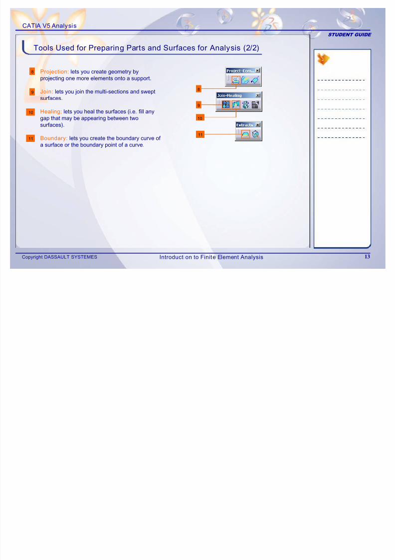
Tools Used for Preparing Parts and Surfaces for Analysis (2/2)
8
9
10
11
8
9
10
11
Projection: lets you create geometry byprojecting one more elements onto a support.
Join: lets you join the multi-sections and swept
surfaces.
Healing: lets you heal the surfaces (i.e. fill anygap that may be appearing between twosurfaces).
Boundary: lets you create the boundary curve of
a surface or the boundary point of a curve.
Introduction to Finite Element Analysis
7/16/2019 Edu Cat en v5a Fb v5r19
http://slidepdf.com/reader/full/edu-cat-en-v5a-fb-v5r19 14/172
CATIA V5 Analysis
STUDENT GUIDE
Copyright DASSAULT SYSTEMES 14
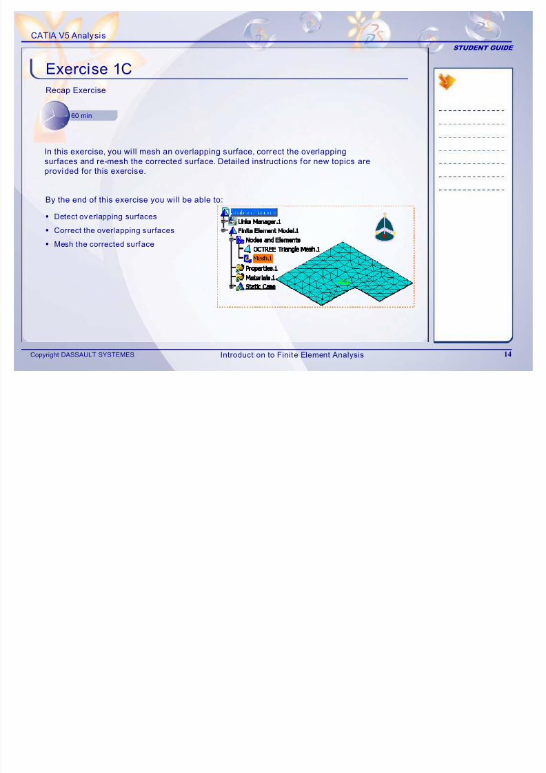
Exercise 1CRecap Exercise
60 min
By the end of this exercise you wi ll be able to: Detect overlapping surfaces
Correct the overlapping surfaces
Mesh the corrected surface
In this exercise, you wi ll mesh an overlapping surface, correct the overlapping
surfaces and re-mesh the corrected surface. Detailed instructions for new topics are
provided for this exercise.
Introduction to Finite Element Analysis
7/16/2019 Edu Cat en v5a Fb v5r19
http://slidepdf.com/reader/full/edu-cat-en-v5a-fb-v5r19 15/172
CATIA V5 Analysis
STUDENT GUIDE
Copyright DASSAULT SYSTEMES 15
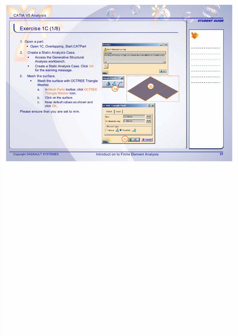
Exercise 1C (1/8)
1. Open a part.
Open 1C_Overlapping_Start.CATPart
2. Create a Static Analysis Case.
Access the Generative StructuralAnalysis workbench.
Create a Static Analysis Case. Click OK
for the warning message.
3. Mesh the surface.
Mesh the surface with OCTREE TriangleMesher.
a. In Mesh Parts toolbar, click OCTREETriangle Mesher icon.
b. Click on the surface.
c. Keep default values as shown andclick OK.
3a
3c
3b
Please ensure that you are set to mm.
Introduction to Finite Element Analysis
7/16/2019 Edu Cat en v5a Fb v5r19
http://slidepdf.com/reader/full/edu-cat-en-v5a-fb-v5r19 16/172
CATIA V5 Analysis
STUDENT GUIDE
Copyright DASSAULT SYSTEMES 16
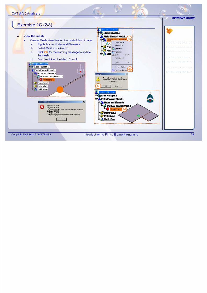
Exercise 1C (2/8)
4. View the mesh.
Create Mesh visualization to create Mesh image.
a. Right-click on Nodes and Elements.
b. Select Mesh visualization.
c. Click OK for the warning message to updatethe mesh.
d. Double-click on the Mesh Error.1.
4a
4b
4c
4d
Introduction to Finite Element Analysis
7/16/2019 Edu Cat en v5a Fb v5r19
http://slidepdf.com/reader/full/edu-cat-en-v5a-fb-v5r19 17/172
CATIA V5 Analysis
STUDENT GUIDE
Copyright DASSAULT SYSTEMES 17
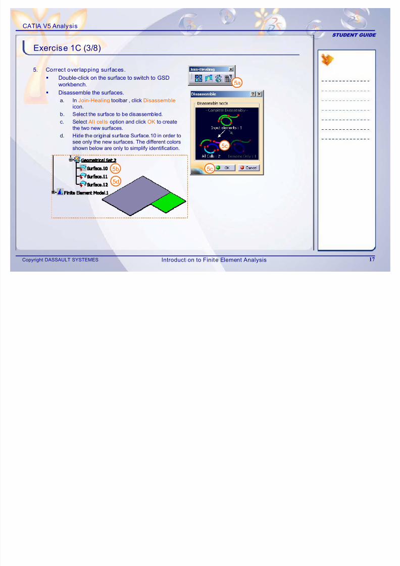
Exercise 1C (3/8)
5. Correct overlapping surfaces.
Double-click on the surface to switch to GSDworkbench.
Disassemble the surfaces.
a. In Join-Healing toolbar , click Disassembleicon.
b. Select the surface to be disassembled.
c. Select Al l cel ls option and click OK to createthe two new surfaces.
d. Hide the original surface Surface.10 in order tosee only the new surfaces. The different colors
shown below are only to simplify identification.
5a
5c
5c5b
5d
Introduction to Finite Element Analysis
7/16/2019 Edu Cat en v5a Fb v5r19
http://slidepdf.com/reader/full/edu-cat-en-v5a-fb-v5r19 18/172
CATIA V5 Analysis
STUDENT GUIDE
Copyright DASSAULT SYSTEMES 18
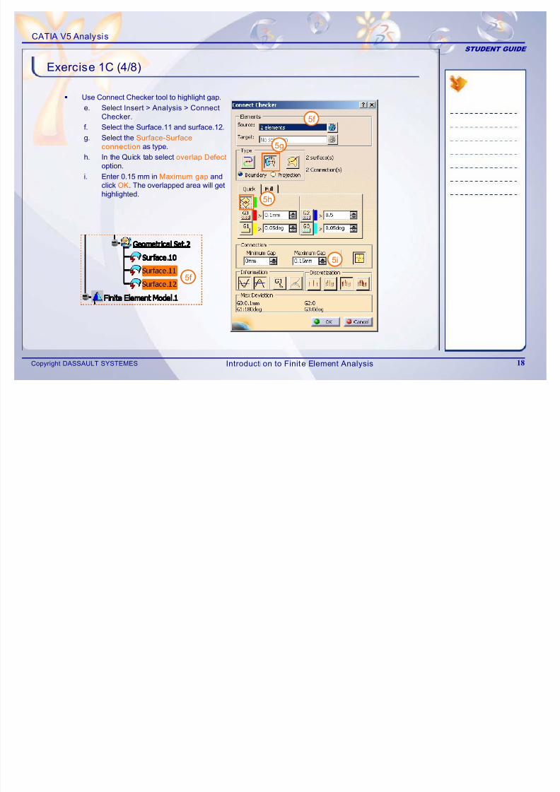
Exercise 1C (4/8)
Use Connect Checker tool to highlight gap.
e. Select Insert > Analysis > Connect
Checker.
f. Select the Surface.11 and surface.12.
g. Select the Surface-Surfaceconnection as type.
h. In the Quick tab select overlap Defect
option.
i. Enter 0.15 mm in Maximum gap andclick OK. The overlapped area will gethighlighted.
5f
5g
5h
5i
5f
Introduction to Finite Element Analysis

7/16/2019 Edu Cat en v5a Fb v5r19
http://slidepdf.com/reader/full/edu-cat-en-v5a-fb-v5r19 19/172
CATIA V5 Analysis
STUDENT GUIDE
Copyright DASSAULT SYSTEMES 19
Exercise 1C (5/8)
Split an overlapping surface.
j. In Project -Combine toolbar, clickProjection icon.
k. In Projected field, select edge of large
surface to be projected on overlappingsurface.
l. In Support field, select small surface andclick OK.
Overlapping
5j
6d
5k5l
5l
5k
Introduction to Finite Element Analysis
7/16/2019 Edu Cat en v5a Fb v5r19
http://slidepdf.com/reader/full/edu-cat-en-v5a-fb-v5r19 20/172
CATIA V5 Analysis
STUDENT GUIDE
Copyright DASSAULT SYSTEMES 20
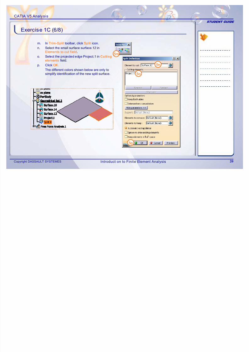
Exercise 1C (6/8)
m. In Trim-Split toolbar, click Split icon.
n. Select the small surface surface.12 inElements to cut f ield.
o. Select the projected edge Project.1 in Cutting
elements field.
p. Click OK.
The different colors shown below are only tosimplify identification of the new split surface.
5m
5n
5o
5p
Introduction to Finite Element Analysis
7/16/2019 Edu Cat en v5a Fb v5r19
http://slidepdf.com/reader/full/edu-cat-en-v5a-fb-v5r19 21/172
CATIA V5 Analysis
STUDENT GUIDE
Copyright DASSAULT SYSTEMES 21
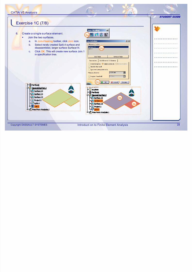
Exercise 1C (7/8)
6. Create a single surface element.
J oin the two surfaces.
a. In Join-Healing toolbar, click Join icon.
b. Select newly created Split.4 surface and
disassembled, larger surface Surface14.c. Click OK. This will create new surface Join.1
in specification tree.
6a
6b
6b
6b
6c
Introduction to Finite Element Analysis
7/16/2019 Edu Cat en v5a Fb v5r19
http://slidepdf.com/reader/full/edu-cat-en-v5a-fb-v5r19 22/172
CATIA V5 Analysis
STUDENT GUIDE
Copyright DASSAULT SYSTEMES 22
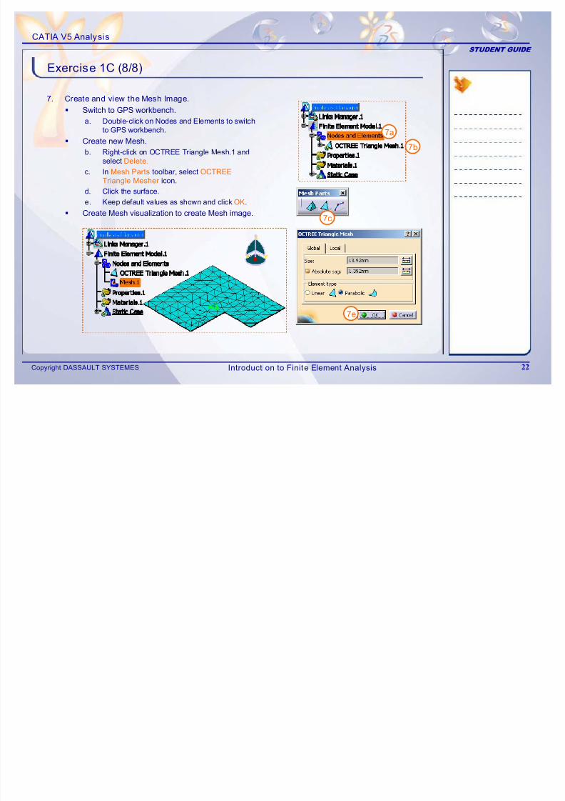
Exercise 1C (8/8)
7. Create and view the Mesh Image.
Switch to GPS workbench.
a. Double-click on Nodes and Elements to switchto GPS workbench.
Create new Mesh.b. Right-click on OCTREE Triangle Mesh.1 and
select Delete.
c. In Mesh Parts toolbar, select OCTREE
Triangle Mesher icon.
d. Click the surface.
e. Keep default values as shown and click OK.
Create Mesh visualization to create Mesh image.
7a
7b
7c
7e
Introduction to Finite Element Analysis
7/16/2019 Edu Cat en v5a Fb v5r19
http://slidepdf.com/reader/full/edu-cat-en-v5a-fb-v5r19 23/172
CATIA V5 Analysis
STUDENT GUIDE
Copyright DASSAULT SYSTEMES 23
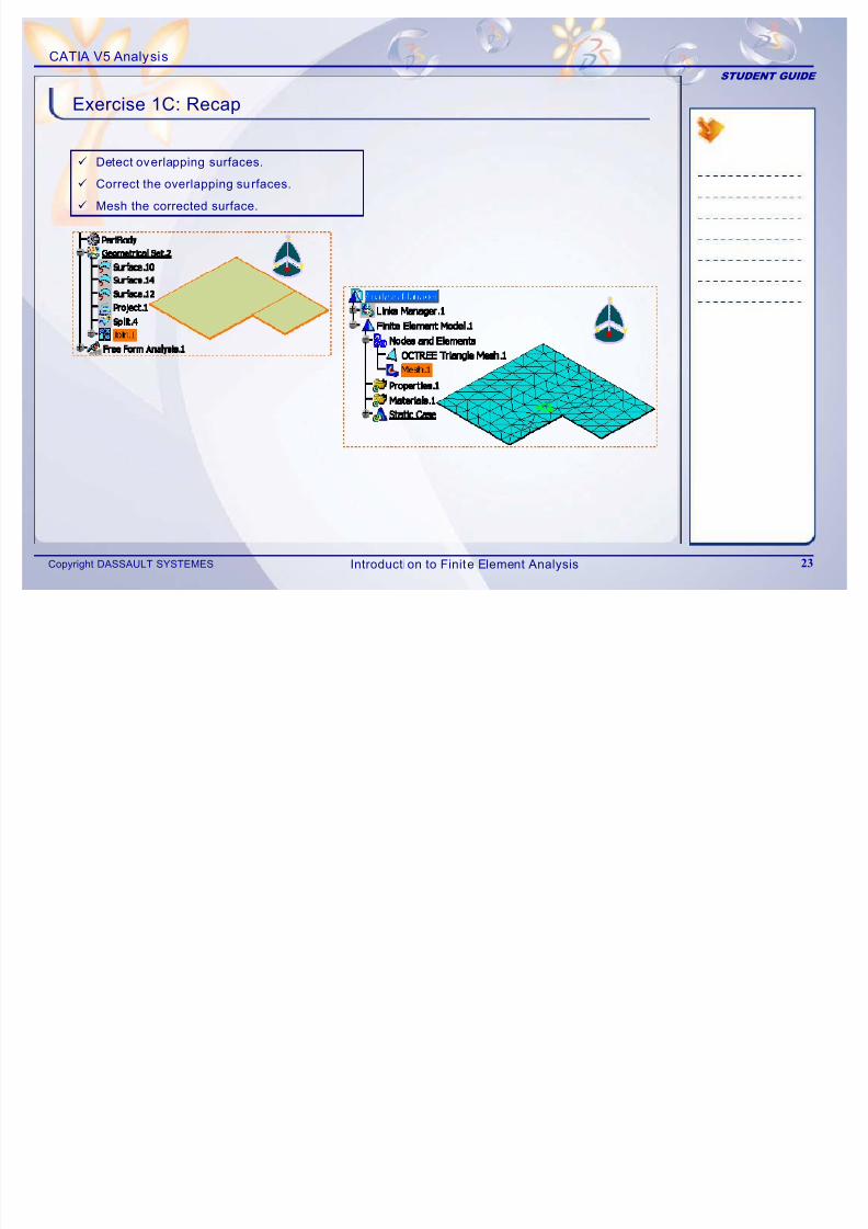
Exercise 1C: Recap
9 Detect overlapping surfaces.
9 Correct the overlapping surfaces.
9 Mesh the corrected surface.
Introduction to Finite Element Analysis
7/16/2019 Edu Cat en v5a Fb v5r19
http://slidepdf.com/reader/full/edu-cat-en-v5a-fb-v5r19 24/172
CATIA V5 Analysis
STUDENT GUIDE
Copyright DASSAULT SYSTEMES 24
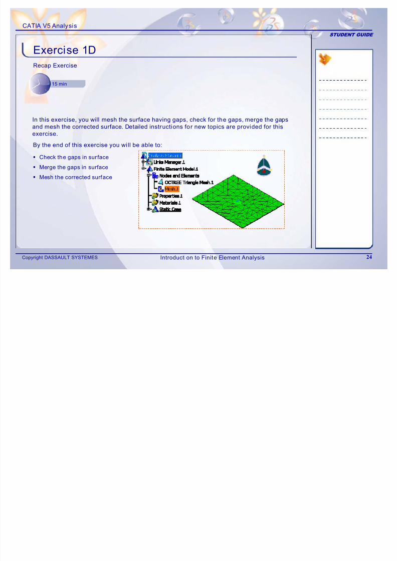
Exercise 1DRecap Exercise
15 min
By the end of this exercise you wi ll be able to:
Check the gaps in sur face
Merge the gaps in surface
Mesh the corrected surface
In this exercise, you will mesh the surface having gaps, check for the gaps, merge the gaps
and mesh the corrected surface. Detailed instructions for new topics are provided for this
exercise.
Introduction to Finite Element Analysis
7/16/2019 Edu Cat en v5a Fb v5r19
http://slidepdf.com/reader/full/edu-cat-en-v5a-fb-v5r19 25/172
CATIA V5 Analysis
STUDENT GUIDE
Copyright DASSAULT SYSTEMES 25
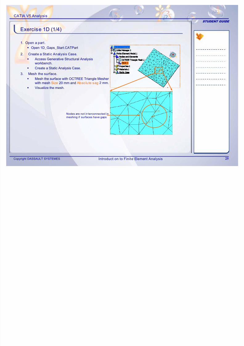
Exercise 1D (1/4)
1. Open a part.
Open 1D_Gaps_Start.CATPart
2. Create a Static Analysis Case.
Access Generative Structural Analysis
workbench.
Create a Static Analysis Case.
3. Mesh the surface.
Mesh the surface with OCTREE Triangle Mesherwith mesh Size 20 mm and Absolute sag 2 mm.
Visualize the mesh.
Nodes are not in terconnected in
meshing if surfaces have gaps
Introduction to Finite Element Analysis
7/16/2019 Edu Cat en v5a Fb v5r19
http://slidepdf.com/reader/full/edu-cat-en-v5a-fb-v5r19 26/172
CATIA V5 Analysis
STUDENT GUIDE
Copyright DASSAULT SYSTEMES 26
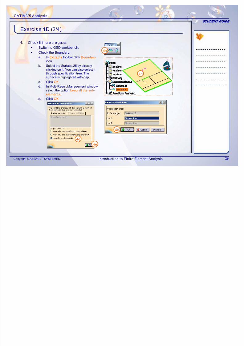
Exercise 1D (2/4)
4. Check i f there are gaps.
Switch to GSD workbench.
Check the Boundary.
a. In Extracts toolbar click Boundary
icon.b. Select the Surface.25 by directly
clicking on it. You can also select itthrough specification tree. Thesurface is highlighted with gap.
c. Click OK.
d. In Multi-Result Management window
select the optionkeep all the sub-
elements.
e. Click OK
4a
4b
4c
4d
4e
Introduction to Finite Element Analysis
7/16/2019 Edu Cat en v5a Fb v5r19
http://slidepdf.com/reader/full/edu-cat-en-v5a-fb-v5r19 27/172
CATIA V5 Analysis
STUDENT GUIDE
Copyright DASSAULT SYSTEMES 27
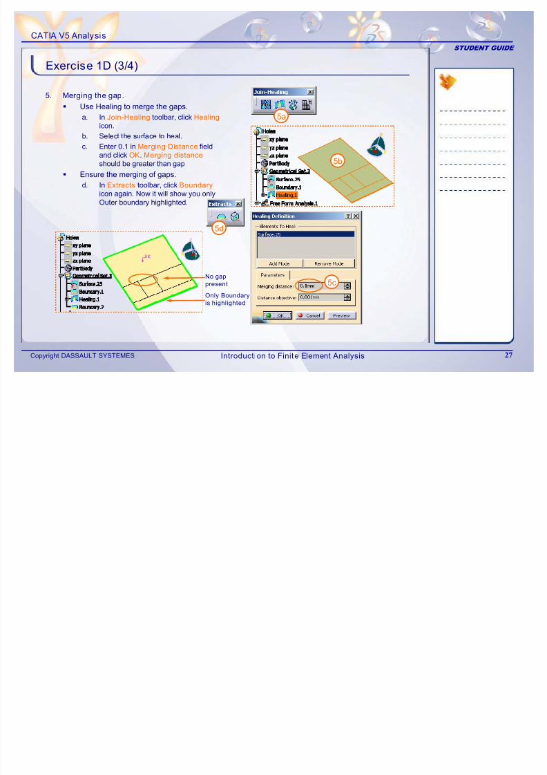
Exercise 1D (3/4)
5. Merging the gap.
Use Healing to merge the gaps.
a. In Join-Healing toolbar, click Healing
icon.
b. Select the surface to heal.c. Enter 0.1 in Merging Distance field
and click OK. Merging distance
should be greater than gap
Ensure the merging of gaps.
d. In Extracts toolbar, click Boundary
icon again. Now it will show you onlyOuter boundary highlighted.
Only Boundary
is highlighted
No gap
present
5a
5b
5c
5d
Introduction to Finite Element Analysis
7/16/2019 Edu Cat en v5a Fb v5r19
http://slidepdf.com/reader/full/edu-cat-en-v5a-fb-v5r19 28/172
CATIA V5 Analysis
STUDENT GUIDE
Copyright DASSAULT SYSTEMES 28
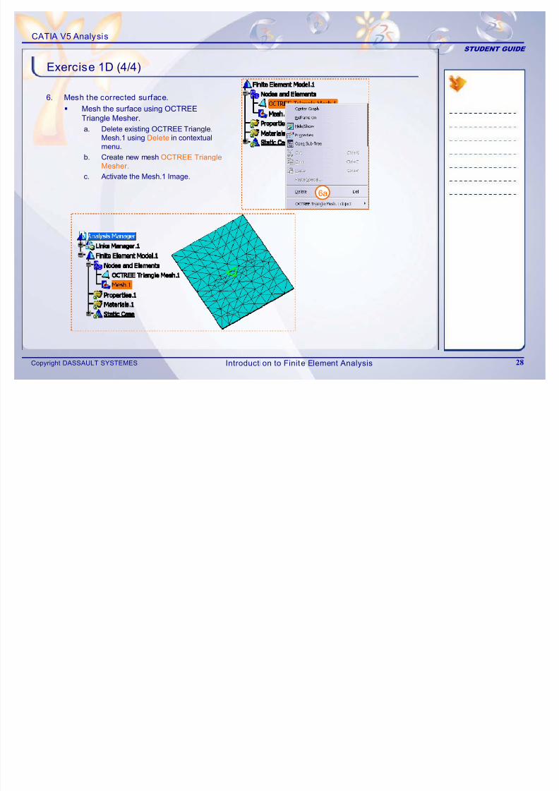
Exercise 1D (4/4)
6. Mesh the corrected surface.
Mesh the surface using OCTREE Triangle Mesher.
a. Delete existing OCTREE Triangle.
Mesh.1 using Delete in contextualmenu.
b. Create new mesh OCTREE Triangle
Mesher.
c. Activate the Mesh.1 Image.
6a
Introduction to Finite Element Analysis
7/16/2019 Edu Cat en v5a Fb v5r19
http://slidepdf.com/reader/full/edu-cat-en-v5a-fb-v5r19 29/172
CATIA V5 Analysis
STUDENT GUIDE
Copyright DASSAULT SYSTEMES 29
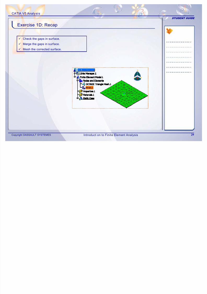
Exercise 1D: Recap
9 Check the gaps in surface.
9 Merge the gaps in surface.
9 Mesh the corrected surface.
Introduction to Finite Element Analysis
7/16/2019 Edu Cat en v5a Fb v5r19
http://slidepdf.com/reader/full/edu-cat-en-v5a-fb-v5r19 30/172
CATIA V5 Analysis
STUDENT GUIDE
Copyright DASSAULT SYSTEMES 30
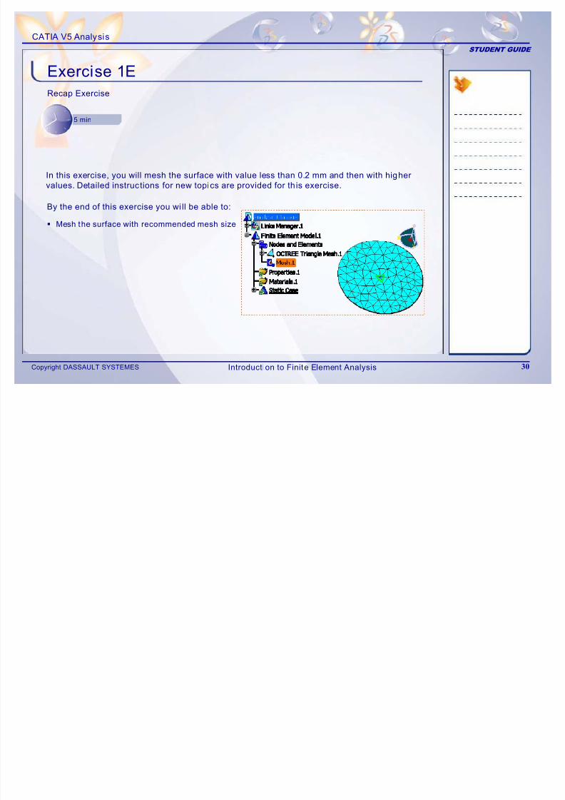
Exercise 1ERecap Exercise
5 min
By the end of this exercise you wi ll be able to:
Mesh the surface with recommended mesh size
In this exercise, you will mesh the surface with value less than 0.2 mm and then with higher
values. Detailed instructions for new topics are provided for th is exercise.
Introduction to Finite Element Analysis
7/16/2019 Edu Cat en v5a Fb v5r19
http://slidepdf.com/reader/full/edu-cat-en-v5a-fb-v5r19 31/172
CATIA V5 Analysis
STUDENT GUIDE
Copyright DASSAULT SYSTEMES 31
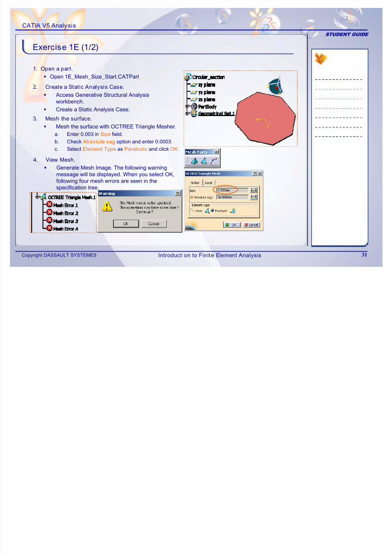
Exercise 1E (1/2)
1. Open a part.
Open 1E_Mesh_Size_Start.CATPart
2. Create a Static Analysis Case.
Access Generative Structural Analysis
workbench. Create a Static Analysis Case.
3. Mesh the surface.
Mesh the surface with OCTREE Triangle Mesher.
a. Enter 0.003 in Size field.
b. Check Absolute sag option and enter 0.0003.
c. Select Element Type as Parabolic and click OK.
4. View Mesh.
Generate Mesh Image. The following warningmessage will be displayed. When you select OK,following four mesh errors are seen in thespecification tree.
Introduction to Finite Element Analysis
7/16/2019 Edu Cat en v5a Fb v5r19
http://slidepdf.com/reader/full/edu-cat-en-v5a-fb-v5r19 32/172
CATIA V5 Analysis
STUDENT GUIDE
Copyright DASSAULT SYSTEMES 32
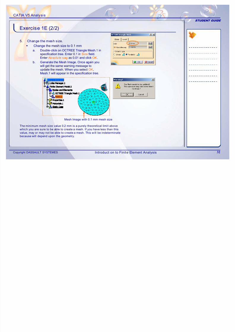
Exercise 1E (2/2)
5. Change the mesh size.
Change the mesh size to 0.1 mm
a. Double-click on OCTREE Triangle Mesh.1 inspecification tree. Enter 0.1 in Size field.Enter Absolute sag as 0.01 and click OK.
b. Generate the Mesh Image. Once again youwill get the same warning message toupdate the mesh. When you select OK,Mesh.1 will appear in the specification tree.
Mesh Image with 0.1 mm mesh size
The minimum mesh size value 0.2 mm is a purely theoretical limi t above
which you are sure to be able to create a mesh. If you have less than this
value, may or may not be able to create a mesh. This w ill be indeterminate
because will depend upon the geometry.
Introduction to Finite Element Analysis
7/16/2019 Edu Cat en v5a Fb v5r19
http://slidepdf.com/reader/full/edu-cat-en-v5a-fb-v5r19 33/172
CATIA V5 Analysis
STUDENT GUIDE
Copyright DASSAULT SYSTEMES 33
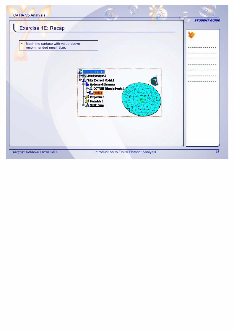
Exercise 1E: Recap
9 Mesh the surface with value above
recommended mesh size.
Introduction to Finite Element Analysis
7/16/2019 Edu Cat en v5a Fb v5r19
http://slidepdf.com/reader/full/edu-cat-en-v5a-fb-v5r19 34/172
CATIA V5 Analysis
STUDENT GUIDE
Copyright DASSAULT SYSTEMES 34
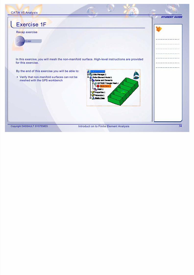
Exercise 1FRecap exercise
5 min
By the end of this exercise you wi ll be able to:
Verify that non-manifold surfaces can not be
meshed with the GPS workbench
In this exercise, you wi ll mesh the non-manifold surface. High-level inst ructions are provided
for this exercise.
Introduction to Finite Element Analysis
7/16/2019 Edu Cat en v5a Fb v5r19
http://slidepdf.com/reader/full/edu-cat-en-v5a-fb-v5r19 35/172
CATIA V5 Analysis
STUDENT GUIDE
Copyright DASSAULT SYSTEMES 35
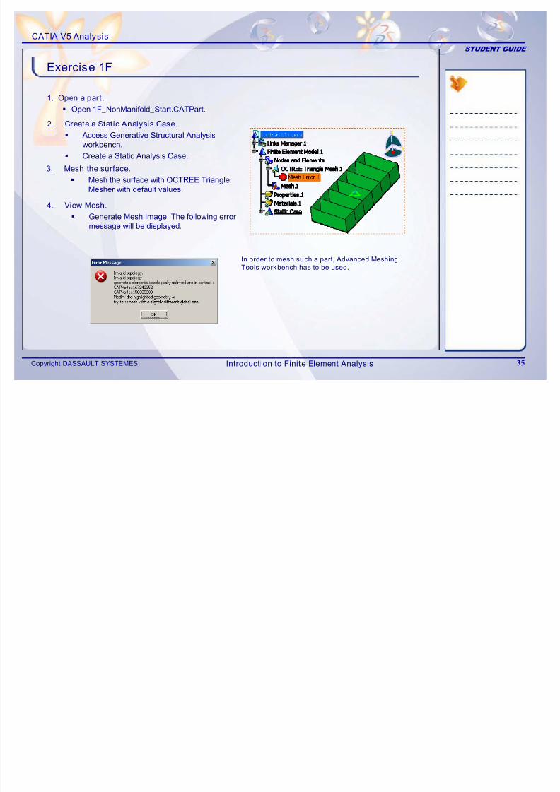
Exercise 1F
1. Open a part.
Open 1F_NonManifold_Start.CATPart.
2. Create a Static Analysis Case.
Access Generative Structural Analysis
workbench. Create a Static Analysis Case.
3. Mesh the surface.
Mesh the surface with OCTREE TriangleMesher with default values.
4. View Mesh.
Generate Mesh Image. The following errormessage will be displayed.
In order to mesh such a part, Advanced Meshing
Tools workbench has to be used.
Introduction to Finite Element Analysis
CATIA V5 A l i
7/16/2019 Edu Cat en v5a Fb v5r19
http://slidepdf.com/reader/full/edu-cat-en-v5a-fb-v5r19 36/172
CATIA V5 Analysis
STUDENT GUIDE
Copyright DASSAULT SYSTEMES 36
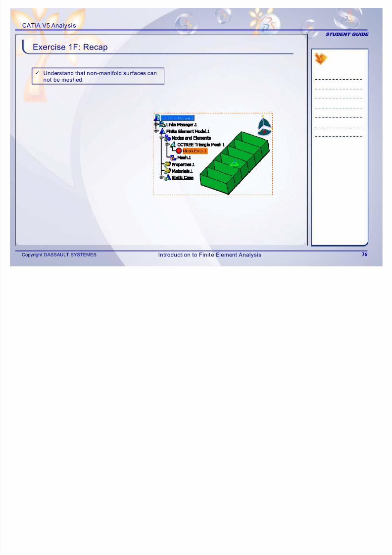
9 Understand that non-manifold surfaces can
not be meshed.
Exercise 1F: Recap
Introduction to Finite Element Analysis
CATIA V5 A l i
7/16/2019 Edu Cat en v5a Fb v5r19
http://slidepdf.com/reader/full/edu-cat-en-v5a-fb-v5r19 37/172
CATIA V5 Analysis
STUDENT GUIDE
Copyright DASSAULT SYSTEMES 37
2
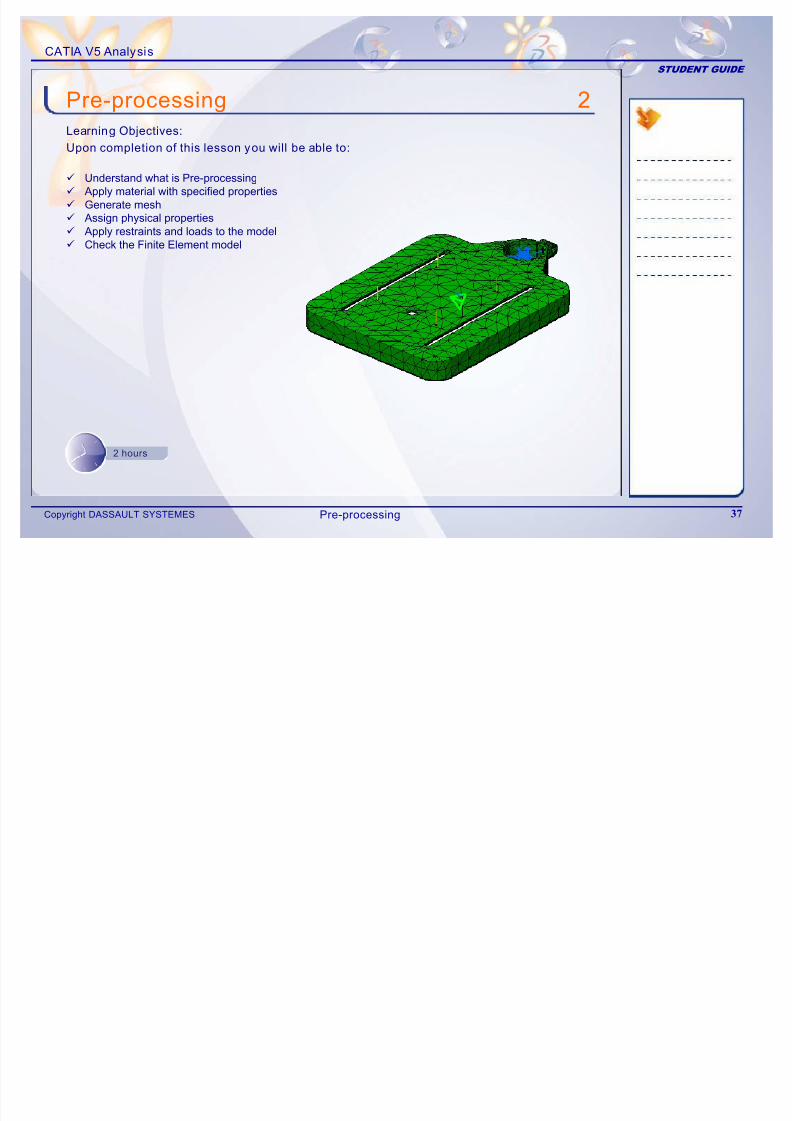
9 Understand what is Pre-processing9 Apply material with specified properties
9 Generate mesh9 Assign physical properties9 Apply restraints and loads to the model9 Check the Finite Element model
Pre-processingLearning Objectives:
Upon completion of this lesson you will be able to:
2 hours
Pre-processing
CATIA V5 Analysis
7/16/2019 Edu Cat en v5a Fb v5r19
http://slidepdf.com/reader/full/edu-cat-en-v5a-fb-v5r19 38/172
CATIA V5 Analysis
STUDENT GUIDE
Copyright DASSAULT SYSTEMES 38
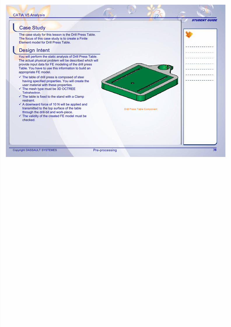
The case study for this lesson is the Drill Press Table. The focus of this case study is to create a FiniteElement model for Drill Press Table.
Design Intent
You will perform the static analysis of Drill Press Table.
The actual physical problem will be described which willprovide input data for FE modeling of the drill press
Table. You have to use this information to build anappropriate FE model.
9 The table of drill press is composed of steelhaving specified properties. You will create theuser material with these properties.
9 The mesh type must be 3D OCTREE Tetrahedron.
9 The table is fixed to the stand with a Clamprestraint.
9 A downward force of 10 N will be applied andtransmitted to the top surface of the tablethrough the drill-bit and work-piece.
9 The validity of the created FE model must bechecked.
Case Study
Drill Press Table Component
Pre-processing
CATIA V5 Analysis
7/16/2019 Edu Cat en v5a Fb v5r19
http://slidepdf.com/reader/full/edu-cat-en-v5a-fb-v5r19 39/172
CATIA V5 Analysis
STUDENT GUIDE
Copyright DASSAULT SYSTEMES 39
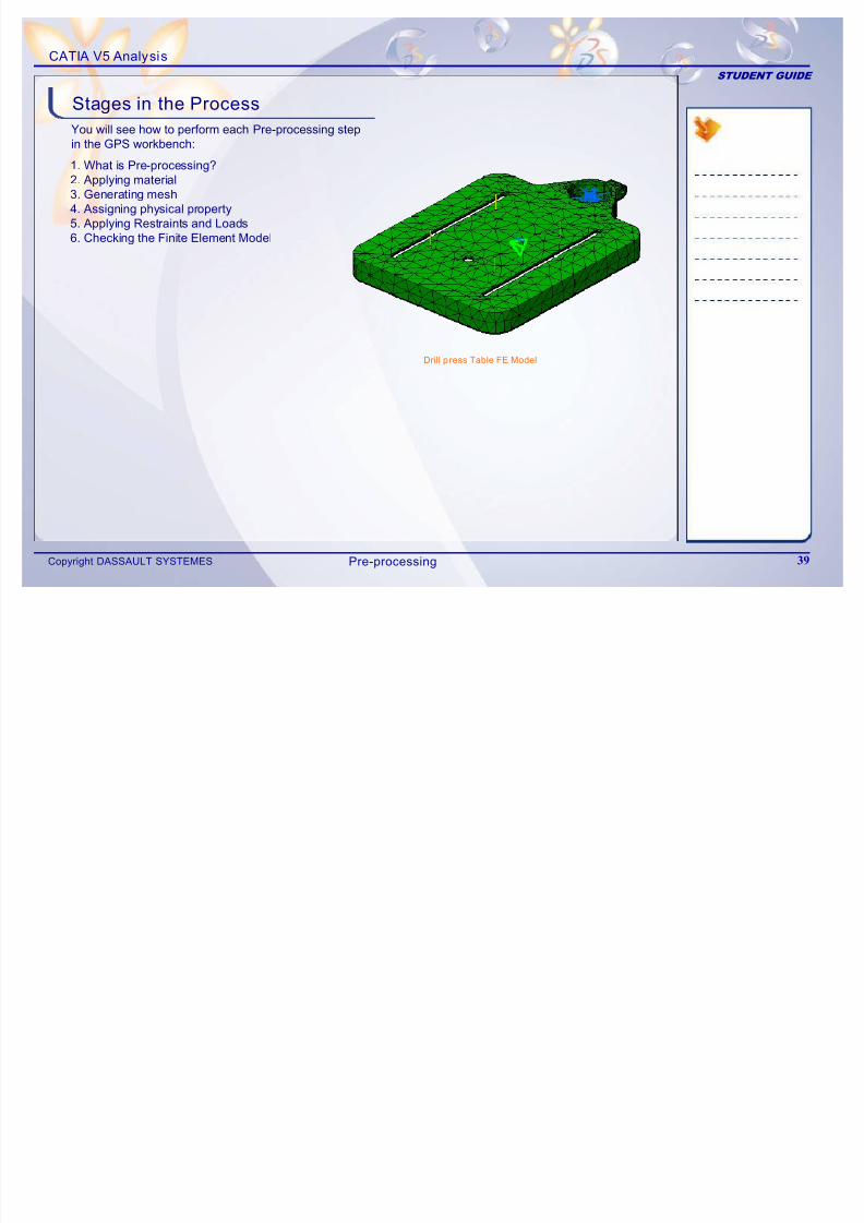
You will see how to perform each Pre-processing stepin the GPS workbench:
1. What is Pre-processing?2. Applying material3. Generating mesh4. Assigning physical property
5. Applying Restraints and Loads6. Checking the Finite Element Model
Stages in the Process
Drill p ress Table FE Model
Pre-processing
CATIA V5 Analysis
7/16/2019 Edu Cat en v5a Fb v5r19
http://slidepdf.com/reader/full/edu-cat-en-v5a-fb-v5r19 40/172
CATIA V5 Analysis
STUDENT GUIDE
Copyright DASSAULT SYSTEMES 40
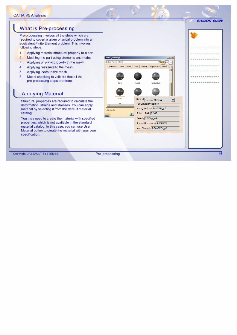
Pre-processing involves all the steps which arerequired to covert a given physical problem into anequivalent Finite Element problem. This involvesfollowing steps:
1. Applying material structural property to a part
2. Meshing the part using elements and nodes
3. Applying physical property to the mesh
4. Applying restraints to the mesh
5. Applying loads to the mesh
6. Model checking to validate that all thepre-processing steps are done.
Applying Material
Structural properties are required to calculate thedeformation, strains and stresses. You can applymaterial by selecting it from the default materialcatalog.
What is Pre-processing
You may need to create the material with specifiedproperties, which is not available in the standardmaterial catalog. In this case, you can use UserMaterial option to create the material with your ownspecification.
Pre-processing
CATIA V5 Analysis
7/16/2019 Edu Cat en v5a Fb v5r19
http://slidepdf.com/reader/full/edu-cat-en-v5a-fb-v5r19 41/172
CATIA V5 Analysis
STUDENT GUIDE
Copyright DASSAULT SYSTEMES 41
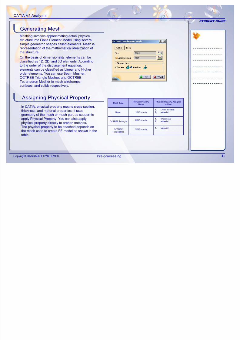
Meshing involves approximating actual physicalstructure into Finite Element Model using severalsimple geometric shapes called elements. Mesh isrepresentation of the mathematical idealization of the structure.
Assigning Physical Property
In CATIA, physical property means cross-section,thickness, and material properties. It usesgeometry of the mesh or mesh part as support toapply Physical Property. You can also applyphysical property directly to orphan meshes.
The physical property to be attached depends onthe mesh used to create FE model as shown in thetable.
Generating Mesh
On the basis of dimensionality, elements can be
classified as 1D, 2D, and 3D elements. Accordingto the order of the displacement equation,elements can be classified as Linear and Higherorder elements. You can use Beam Mesher,OCTREE Triangle Mesher, and OCTREE
Tetrahedron Mesher to mesh wireframes,surfaces, and solids respectively.
1. Material3D PropertyOCTREE
Tetrahedron
1. Thickness
2. Material
1. Cross-sec tion
2. Material
Physical Property Assignedto Mesh
OCTREE Triangle
Beam
Mesh Type
2D Property
Physical PropertyName
1D Property
Pre-processing
CATIA V5 Analysis
7/16/2019 Edu Cat en v5a Fb v5r19
http://slidepdf.com/reader/full/edu-cat-en-v5a-fb-v5r19 42/172
y
STUDENT GUIDE
Copyright DASSAULT SYSTEMES 42
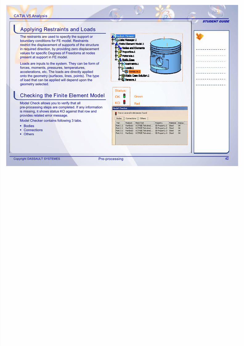
The restraints are used to specify the support orboundary conditions for FE model. Restraintsrestrict the displacement of supports of the structurein required direction, by providing zero displacementvalues for specific Degrees of Freedoms at nodespresent at support in FE model.
Checking the Finite Element Model
Model Check allows you to verify that allpre-processing steps are completed. If any informationis missing, it shows status KO against that row andprovides related error message.
Bodies Connections Others
Green
Red
Applying Restraints and Loads
Loads are inputs to the system. They can be form of forces, moments, pressures, temperatures,accelerations, etc. The loads are directly appliedonto the geometry (surfaces, lines, points). The typeof load that can be applied will depend upon thegeometry selected.
Status:
OK
KO
Model Checker contains following 3 tabs.
Pre-processing
CATIA V5 Analysis
7/16/2019 Edu Cat en v5a Fb v5r19
http://slidepdf.com/reader/full/edu-cat-en-v5a-fb-v5r19 43/172
y
STUDENT GUIDE
Copyright DASSAULT SYSTEMES 43
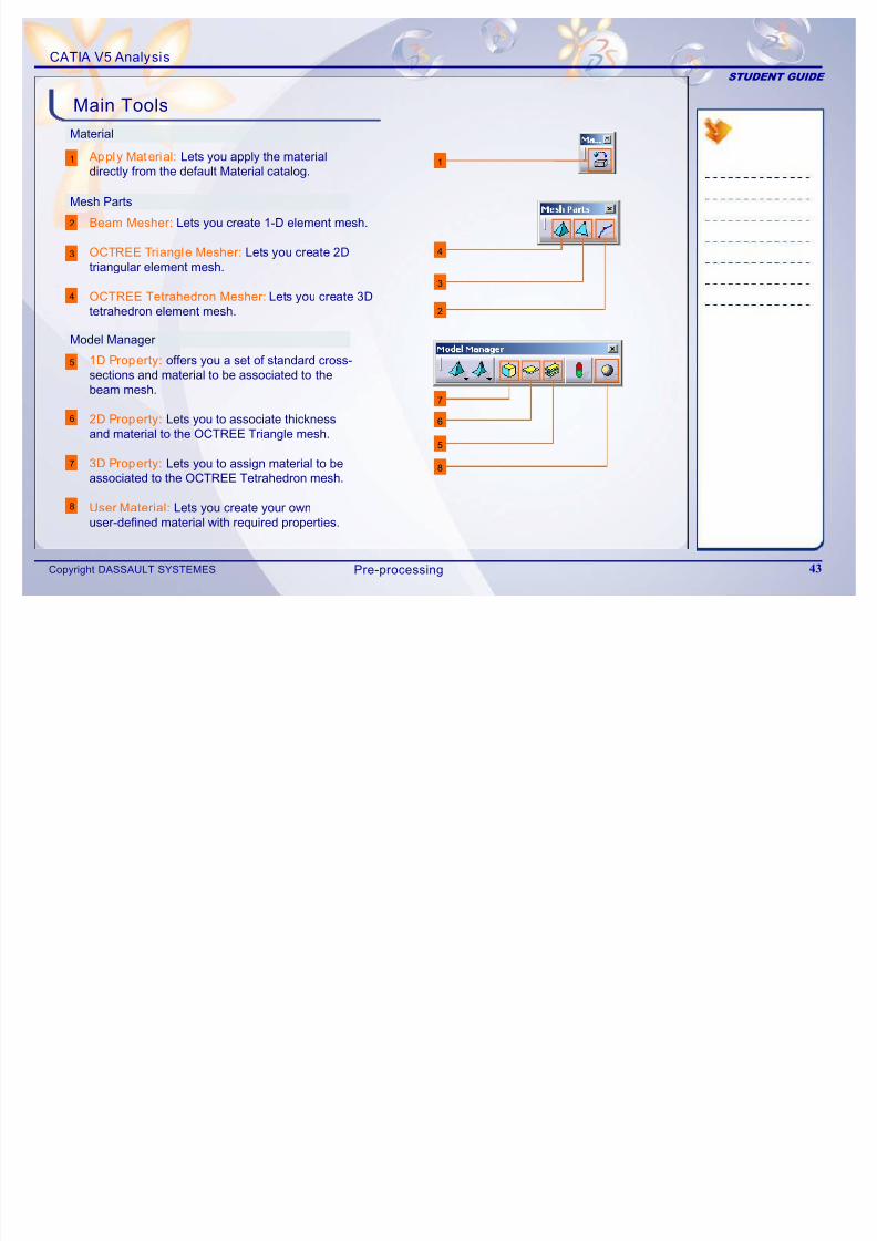
Material
Main Tools
11
8
2
3
Mesh Parts
4
1D Property: offers you a set of standard cross-sections and material to be associated to thebeam mesh.
2D Property: Lets you to associate thicknessand material to the OCTREE Triangle mesh.
3D Property: Lets you to assign material to beassociated to the OCTREE Tetrahedron mesh.
User Material: Lets you create your ownuser-defined material with required properties.
Apply Material: Lets you apply the materialdirectly from the default Material catalog.
Beam Mesher: Lets you create 1-D element mesh.
OCTREE Triangle Mesher: Lets youcreate 2Dtriangular element mesh.
OCTREE Tetrahedron Mesher: Lets youcreate 3Dtetrahedron element mesh.
Model Manager
5
6
7
6
5
7
8
3
2
4
Pre-processing
CATIA V5 Analysis
7/16/2019 Edu Cat en v5a Fb v5r19
http://slidepdf.com/reader/full/edu-cat-en-v5a-fb-v5r19 44/172
STUDENT GUIDE
Copyright DASSAULT SYSTEMES 44
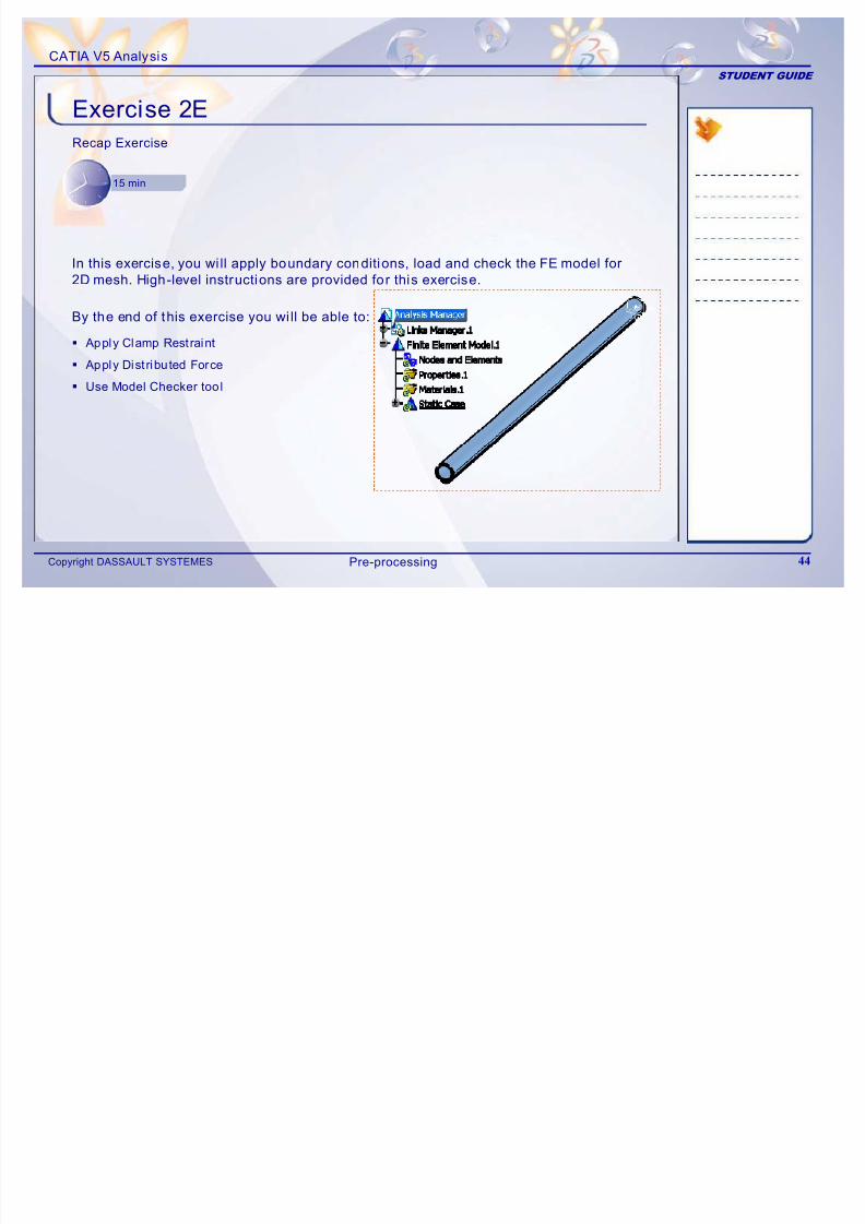
Exercise 2ERecap Exercise
15 min
By the end of this exercise you wi ll be able to:
Apply Clamp Restraint
Apply Dist ributed Force
Use Model Checker tool
In this exercise, you wi ll apply boundary conditions, load and check the FE model for
2D mesh. High-level instructions are provided for this exercise.
Pre-processing
CATIA V5 Analysis
7/16/2019 Edu Cat en v5a Fb v5r19
http://slidepdf.com/reader/full/edu-cat-en-v5a-fb-v5r19 45/172
STUDENT GUIDE
Copyright DASSAULT SYSTEMES 45
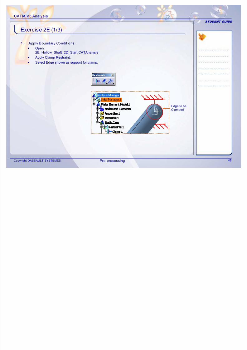
Exercise 2E (1/3)
1. Apply Boundary Condit ions.
Open2E_Hollow_Shaft_2D_Start.CATAnalysis
Apply Clamp Restraint.
Select Edge shown as support for clamp.
Edge to be
Clamped
Pre-processing
CATIA V5 Analysis
7/16/2019 Edu Cat en v5a Fb v5r19
http://slidepdf.com/reader/full/edu-cat-en-v5a-fb-v5r19 46/172
STUDENT GUIDE
Copyright DASSAULT SYSTEMES 46
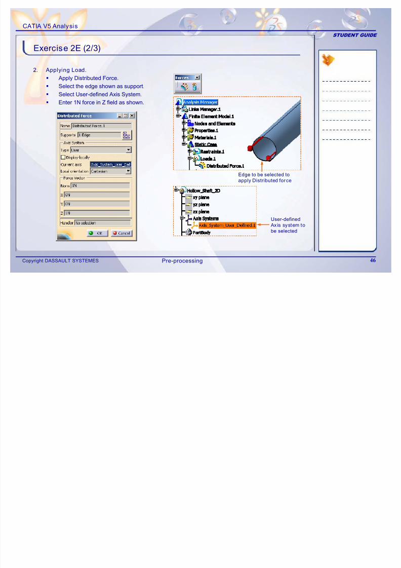
Exercise 2E (2/3)
2. Applying Load.
Apply Distributed Force.
Select the edge shown as support.
Select User-defined Axis System.
Enter 1N force in Z field as shown.
Edge to be selected to
apply Distributed force
User-defined
Axis system to
be selected
Pre-processing
CATIA V5 Analysis
7/16/2019 Edu Cat en v5a Fb v5r19
http://slidepdf.com/reader/full/edu-cat-en-v5a-fb-v5r19 47/172
STUDENT GUIDE
Copyright DASSAULT SYSTEMES 47
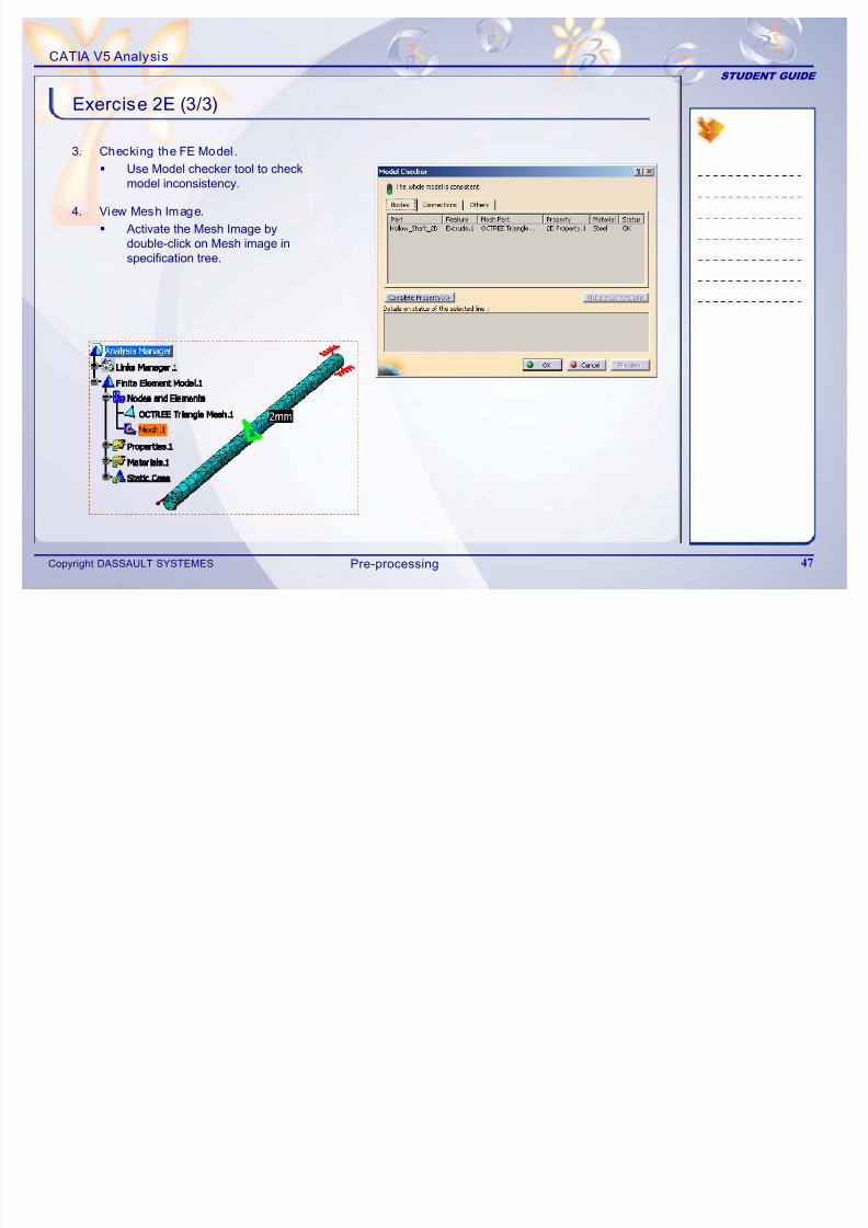
Exercise 2E (3/3)
3. Checking the FE Model.
Use Model checker tool to checkmodel inconsistency.
4. View Mesh Image.
Activate the Mesh Image bydouble-click on Mesh image inspecification tree.
Pre-processing
CATIA V5 Analysis
7/16/2019 Edu Cat en v5a Fb v5r19
http://slidepdf.com/reader/full/edu-cat-en-v5a-fb-v5r19 48/172
STUDENT GUIDE
Copyright DASSAULT SYSTEMES 48
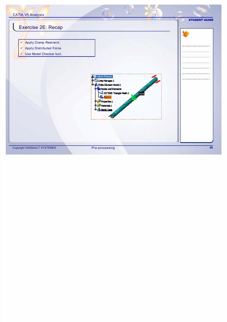
Exercise 2E: Recap
9 Apply Clamp Restraint .
9 Apply Dist ributed Force.
9 Use Model Checker tool.
Pre-processing
CATIA V5 Analysis
STUDENT GUIDE
7/16/2019 Edu Cat en v5a Fb v5r19
http://slidepdf.com/reader/full/edu-cat-en-v5a-fb-v5r19 49/172
STUDENT GUIDE
Copyright DASSAULT SYSTEMES 49
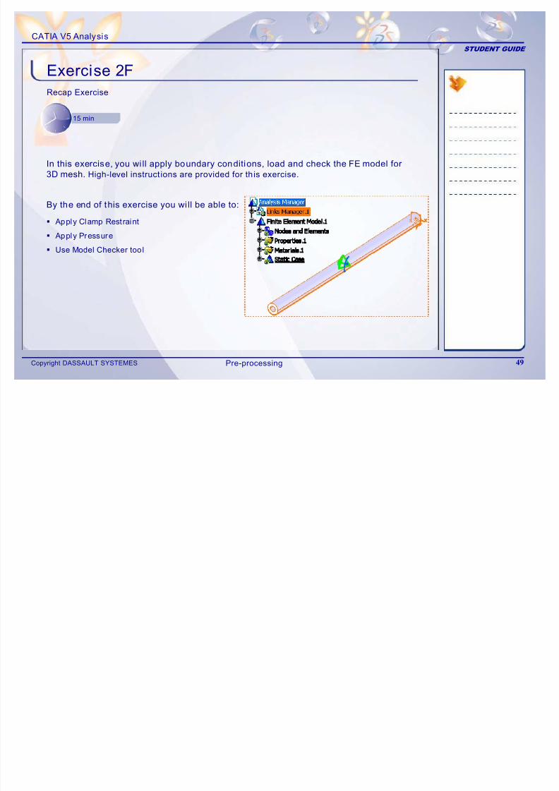
Exercise 2FRecap Exercise
15 min
By the end of this exercise you wi ll be able to:
Apply Clamp Restraint
Apply Pressure
Use Model Checker tool
In this exercise, you wi ll apply boundary conditions, load and check the FE model for
3D mesh. High-level instruct ions are provided for th is exercise.
Pre-processing
CATIA V5 Analysis
STUDENT GUIDE
7/16/2019 Edu Cat en v5a Fb v5r19
http://slidepdf.com/reader/full/edu-cat-en-v5a-fb-v5r19 50/172
STUDENT GUIDE
Copyright DASSAULT SYSTEMES 50
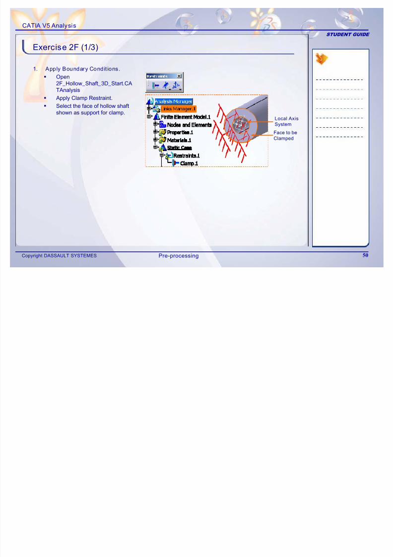
Exercise 2F (1/3)
1. Apply Boundary Condit ions.
Open2F_Hollow_Shaft_3D_Start.CA
TAnalysis
Apply Clamp Restraint.
Select the face of hollow shaftshown as support for clamp.
Face to be
Clamped
Local Axis
System
Pre-processing
CATIA V5 Analysis
STUDENT GUIDE
7/16/2019 Edu Cat en v5a Fb v5r19
http://slidepdf.com/reader/full/edu-cat-en-v5a-fb-v5r19 51/172
STUDENT GUIDE
Copyright DASSAULT SYSTEMES 51
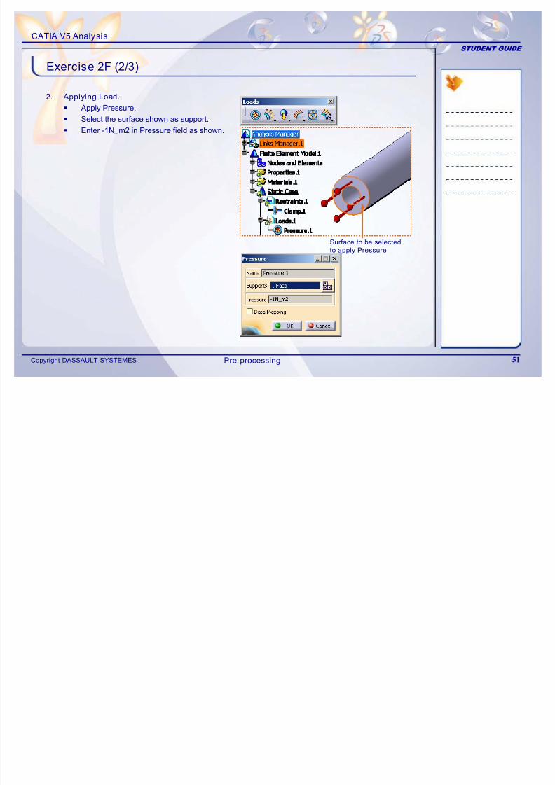
Exercise 2F (2/3)
2. Applying Load.
Apply Pressure.
Select the surface shown as support.
Enter -1N_m2 in Pressure field as shown.
Surface to be selected
to apply Pressure
Pre-processing
CATIA V5 Analysis
STUDENT GUIDE
7/16/2019 Edu Cat en v5a Fb v5r19
http://slidepdf.com/reader/full/edu-cat-en-v5a-fb-v5r19 52/172
STUDENT GUIDE
Copyright DASSAULT SYSTEMES 52
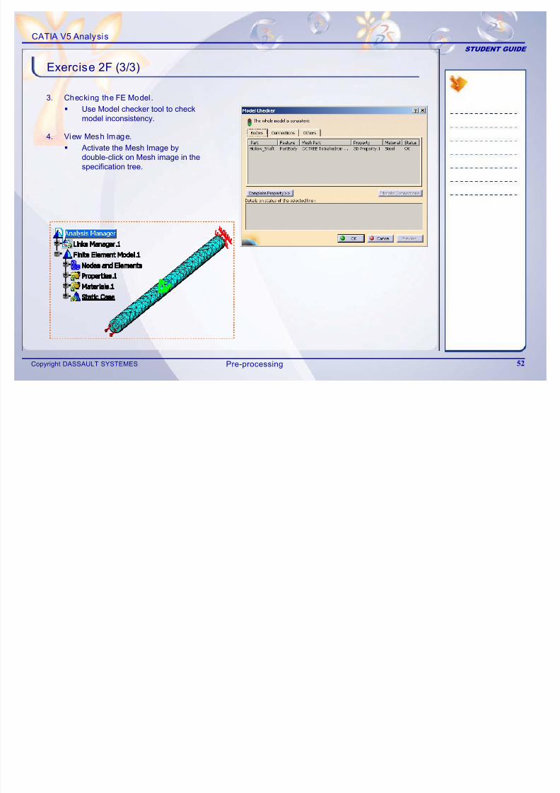
Exercise 2F (3/3)
3. Checking the FE Model.
Use Model checker tool to checkmodel inconsistency.
4. View Mesh Image.
Activate the Mesh Image bydouble-click on Mesh image in thespecification tree.
Pre-processing
CATIA V5 Analysis
STUDENT GUIDE
7/16/2019 Edu Cat en v5a Fb v5r19
http://slidepdf.com/reader/full/edu-cat-en-v5a-fb-v5r19 53/172
STUDENT GUIDE
Copyright DASSAULT SYSTEMES 53
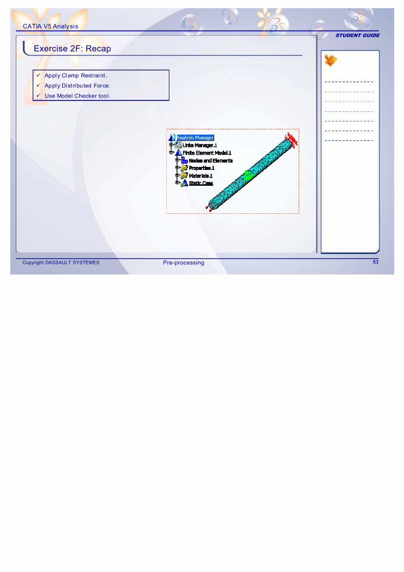
Exercise 2F: Recap
9 Apply Clamp Restraint .
9 Apply Dist ributed Force.
9 Use Model Checker tool.
Pre-processing
CATIA V5 Analysis
STUDENT GUIDE
7/16/2019 Edu Cat en v5a Fb v5r19
http://slidepdf.com/reader/full/edu-cat-en-v5a-fb-v5r19 54/172
Copyright DASSAULT SYSTEMES 54
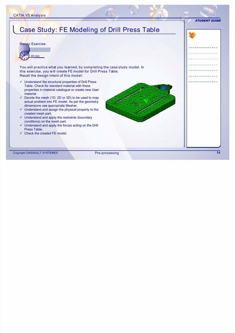
Case Study: FE Modeling of Drill Press TableRecap Exercise
30 min
9 Understand the structural properties of Drill Press Table. Check for standard material with these
properties in material catalogue or create new Usermaterial.9 Decide the mesh (1D, 2D or 3D) to be used to map
actual problem into FE model. As per the geometrydimensions use appropriate Mesher.
9 Understand and assign the physical property to thecreated mesh part.
9 Understand and apply the restraints (boundaryconditions) on the mesh part.
9 Understand and apply the forces acting on the DrillPress Table.
9 Check the created FE model.
You will practice what you learned, by completing the case study model. In
this exercise, you will create FE model for Drill Press Table.
Recall the design intent of th is model:
Pre-processing
CATIA V5 Analysis
STUDENT GUIDE
7/16/2019 Edu Cat en v5a Fb v5r19
http://slidepdf.com/reader/full/edu-cat-en-v5a-fb-v5r19 55/172
Copyright DASSAULT SYSTEMES 55
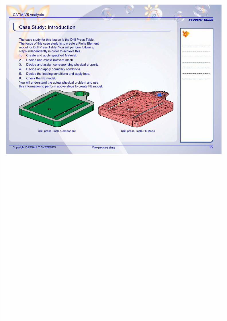
Case Study: Introduction
The case study for this lesson is the Drill Press Table. The focus of this case study is to create a Finite Elementmodel for Drill Press Table. You will perform followingsteps independently in order to achieve this.
Drill press Table Component Drill press Table FE Model
1. Create and apply specified Material.
2. Decide and create relevant mesh.3. Decide and assign corresponding physical property.
4. Decide and apply boundary conditions.
5. Decide the loading conditions and apply load.
6. Check the FE model.
You will understand the actual physical problem and use
this information to perform above steps to create FE model.
Pre-processing
CATIA V5 Analysis
STUDENT GUIDE
7/16/2019 Edu Cat en v5a Fb v5r19
http://slidepdf.com/reader/full/edu-cat-en-v5a-fb-v5r19 56/172
Copyright DASSAULT SYSTEMES 56
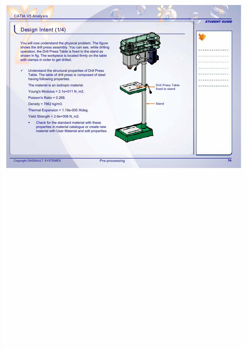
Design Intent (1/4)
You will now understand the physical problem. The figureshows the drill press assembly. You can see, while drillingoperation, the Drill Press Table is fixed to the stand asshown in fig. The workpiece is located firmly on the tablewith clamps in order to get drilled.
Drill Press Table
fixed to stand
Stand
9 Understand the structural properties of Drill Press Table. The table of drill press is composed of steelhaving following properties.
The material is an isotropic material.
Young's Modulus = 2.1e+011 N_m2.
Poisson's Ratio = 0.268.
Density = 7862 kg/m3.
Thermal Expansion = 1.19e-005 /Kdeg.
Yield Strength = 2.6e+008 N_m2.
Check for the standard material with these
properties in material catalogue or create newmaterial with User Material and edit properties.
Pre-processing
CATIA V5 Analysis
STUDENT GUIDE
7/16/2019 Edu Cat en v5a Fb v5r19
http://slidepdf.com/reader/full/edu-cat-en-v5a-fb-v5r19 57/172
Copyright DASSAULT SYSTEMES 57
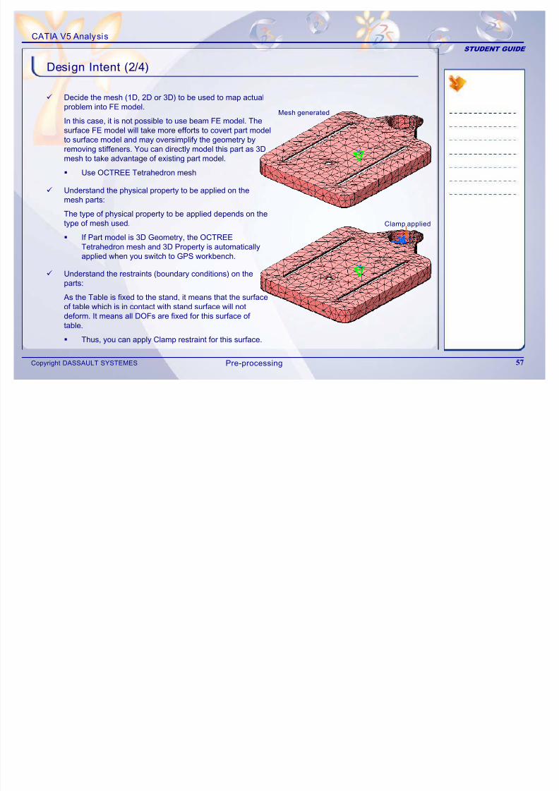
Design Intent (2/4)
9 Decide the mesh (1D, 2D or 3D) to be used to map actualproblem into FE model.
In this case, it is not possible to use beam FE model. Thesurface FE model will take more efforts to covert part modelto surface model and may oversimplify the geometry by
removing stiffeners. You can directly model this part as 3Dmesh to take advantage of existing part model.
Use OCTREE Tetrahedron mesh
9 Understand the physical property to be applied on themesh parts:
The type of physical property to be applied depends on thetype of mesh used.
If Part model is 3D Geometry, the OCTREE Tetrahedron mesh and 3D Property is automaticallyapplied when you switch to GPS workbench.
9 Understand the restraints (boundary conditions) on the
parts:As the Table is fixed to the stand, it means that the surfaceof table which is in contact with stand surface will notdeform. It means all DOFs are fixed for this surface of table.
Thus, you can apply Clamp restraint for this surface.
Clamp applied
Mesh generated
Pre-processing
CATIA V5 Analysis
STUDENT GUIDE
7/16/2019 Edu Cat en v5a Fb v5r19
http://slidepdf.com/reader/full/edu-cat-en-v5a-fb-v5r19 58/172
Copyright DASSAULT SYSTEMES 58
Design Intent (3/4)
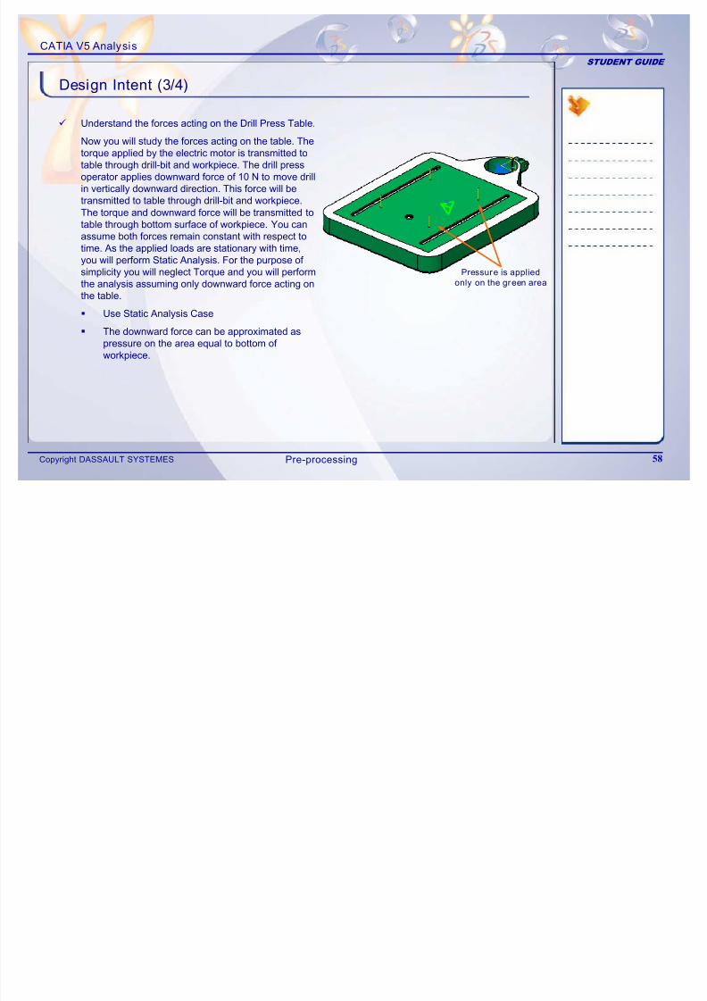
9 Understand the forces acting on the Drill Press Table.
Now you will study the forces acting on the table. Thetorque applied by the electric motor is transmitted totable through drill-bit and workpiece. The drill pressoperator applies downward force of 10 N to move drill
in vertically downward direction. This force will betransmitted to table through drill-bit and workpiece.
The torque and downward force will be transmitted totable through bottom surface of workpiece. You canassume both forces remain constant with respect totime. As the applied loads are stationary with time,you will perform Static Analysis. For the purpose of
simplicity you will neglect Torque and you will performthe analysis assuming only downward force acting onthe table.
Use Static Analysis Case
The downward force can be approximated aspressure on the area equal to bottom of
workpiece.
Pressure is appliedonly on the green area
Pre-processing
CATIA V5 Analysis
STUDENT GUIDE
7/16/2019 Edu Cat en v5a Fb v5r19
http://slidepdf.com/reader/full/edu-cat-en-v5a-fb-v5r19 59/172
Copyright DASSAULT SYSTEMES 59
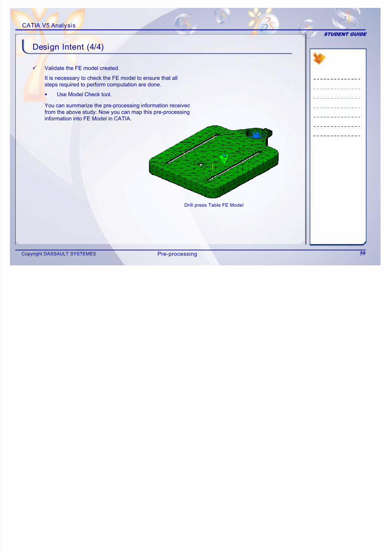
Design Intent (4/4)
You can summarize the pre-processing information receivedfrom the above study: Now you can map this pre-processinginformation into FE Model in CATIA.
9 Validate the FE model created.
It is necessary to check the FE model to ensure that allsteps required to perform computation are done.
Use Model Check tool.
Drill press Table FE Model
Pre-processing
CATIA V5 Analysis
STUDENT GUIDE
7/16/2019 Edu Cat en v5a Fb v5r19
http://slidepdf.com/reader/full/edu-cat-en-v5a-fb-v5r19 60/172
Copyright DASSAULT SYSTEMES 60
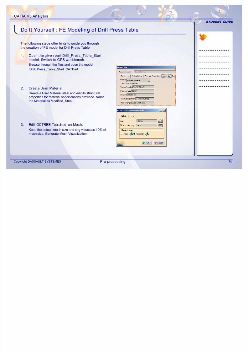
Do It Yourself : FE Modeling of Dril l Press Table
1. Open the given part Drill_Press_Table_Start
model. Switch to GPS workbench.
Browse through the files and open the model‘Drill_Press_Table_Start .CATPart
2. Create User Material.
Create a User Material steel and edit its structural
properties for material specifications provided. Namethe Material as Modified_Steel.
3. Edit OCTREE Tetrahedron Mesh.
Keep the default mesh size and sag values as 10% of mesh size. Generate Mesh Visualization.
The following steps offer hints to guide you throughthe creation of FE model for Drill Press Table.
Pre-processing
CATIA V5 Analysis
STUDENT GUIDE
7/16/2019 Edu Cat en v5a Fb v5r19
http://slidepdf.com/reader/full/edu-cat-en-v5a-fb-v5r19 61/172
Copyright DASSAULT SYSTEMES 61
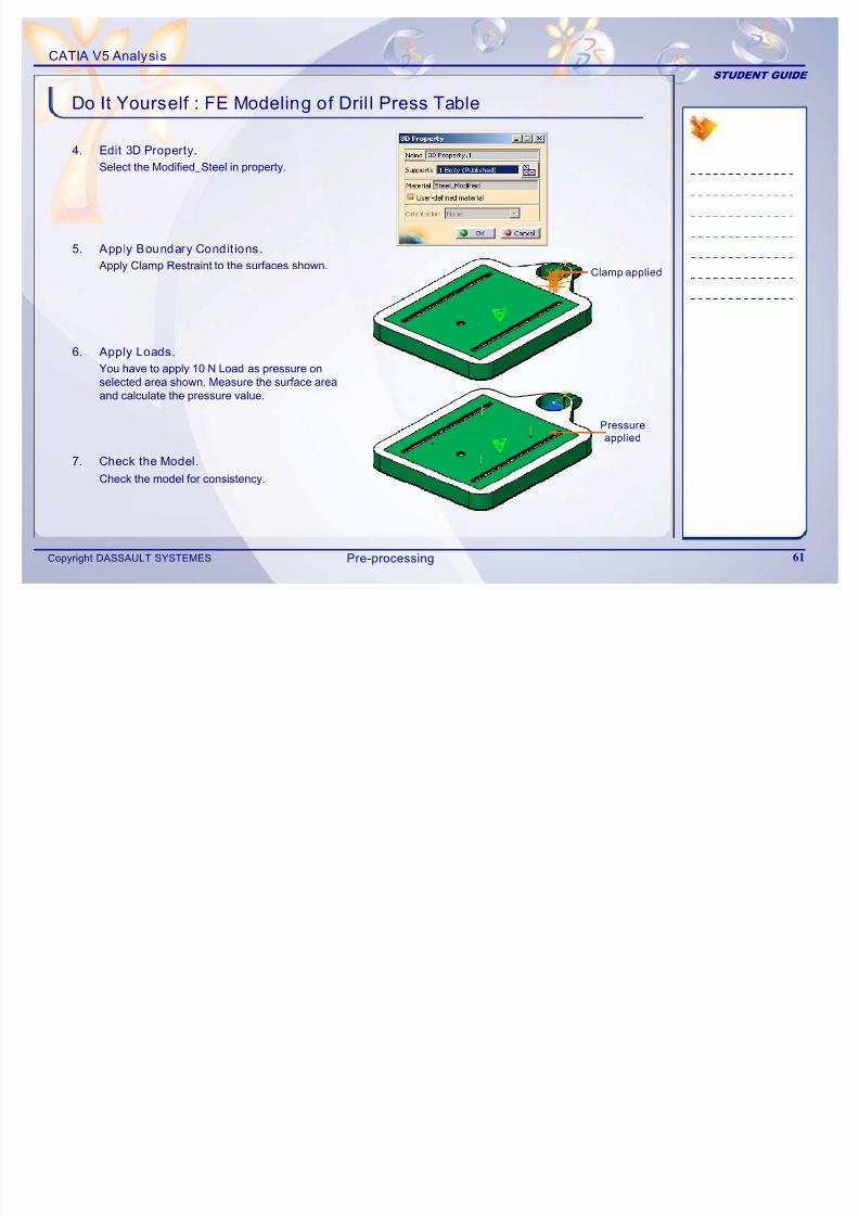
Do It Yourself : FE Modeling of Dril l Press Table
4. Edit 3D Property.
Select the Modified_Steel in property.
5. Apply Boundary Condit ions.
Apply Clamp Restraint to the surfaces shown.
6. Apply Loads.
You have to apply 10 N Load as pressure onselected area shown. Measure the surface areaand calculate the pressure value.
7. Check the Model.
Check the model for consistency.
Clamp applied
Pressure
applied
Pre-processing
CATIA V5 Analysis
STUDENT GUIDE
7/16/2019 Edu Cat en v5a Fb v5r19
http://slidepdf.com/reader/full/edu-cat-en-v5a-fb-v5r19 62/172
Copyright DASSAULT SYSTEMES 62
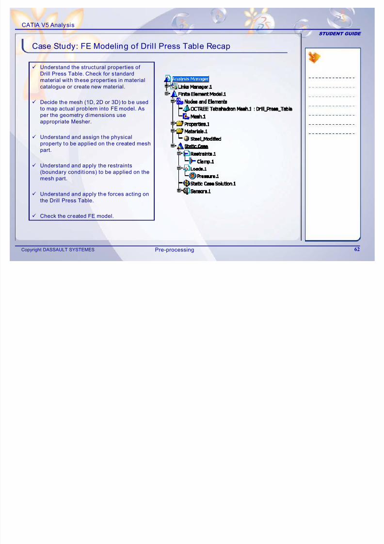
Case Study: FE Modeling of Dril l Press Table Recap
9 Understand the structural properties of
Drill Press Table. Check for standard
material with these properties in material
catalogue or create new material.
9 Decide the mesh (1D, 2D or 3D) to be usedto map actual problem into FE model. As
per the geometry dimensions use
appropriate Mesher.
9 Understand and assign the physical
property to be applied on the created mesh
part.
9 Understand and apply the restraints
(boundary conditions) to be applied on the
mesh part.
9Understand and apply the forces acting onthe Drill Press Table.
9 Check the created FE model.
Pre-processing
CATIA V5 Analysis
STUDENT GUIDE
7/16/2019 Edu Cat en v5a Fb v5r19
http://slidepdf.com/reader/full/edu-cat-en-v5a-fb-v5r19 63/172
Copyright DASSAULT SYSTEMES 63
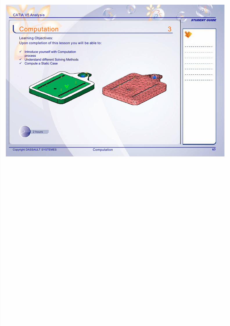
3
9 Introduce yourself with Computationprocess
9Understand different Solving Methods9 Compute a Static Case
Computation
Learning Objectives:
Upon completion of this lesson you will be able to:
2 hours
Computation
CATIA V5 Analysis
STUDENT GUIDE
7/16/2019 Edu Cat en v5a Fb v5r19
http://slidepdf.com/reader/full/edu-cat-en-v5a-fb-v5r19 64/172
Copyright DASSAULT SYSTEMES 64
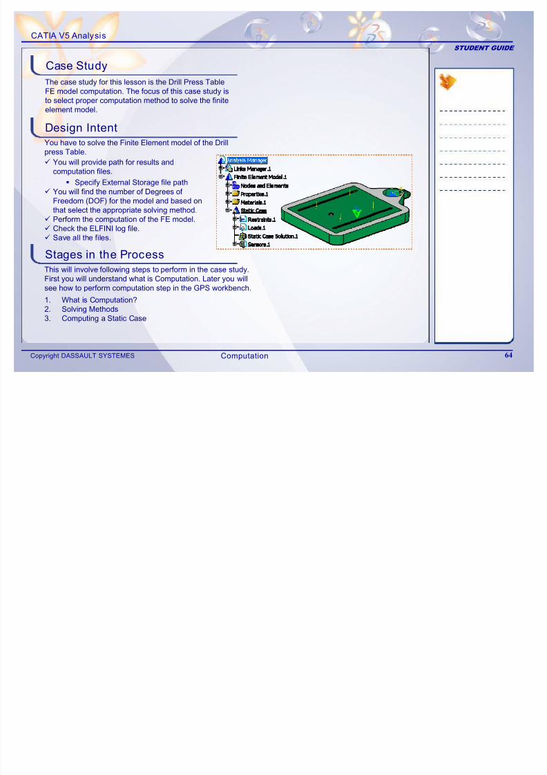
The case study for this lesson is the Drill Press TableFE model computation. The focus of this case study isto select proper computation method to solve the finiteelement model.
Design Intent
Stages in the Process
You have to solve the Finite Element model of the Drillpress Table.
9 You will provide path for results andcomputation files.
Specify External Storage file path9 You will find the number of Degrees of
Freedom (DOF) for the model and based on
that select the appropriate solving method.9 Perform the computation of the FE model.9 Check the ELFINI log file.9 Save all the files.
This will involve following steps to perform in the case study.
First you will understand what is Computation. Later you willsee how to perform computation step in the GPS workbench.
1. What is Computation?2. Solving Methods3. Computing a Static Case
Case Study
Computation
CATIA V5 Analysis
STUDENT GUIDE
7/16/2019 Edu Cat en v5a Fb v5r19
http://slidepdf.com/reader/full/edu-cat-en-v5a-fb-v5r19 65/172
Copyright DASSAULT SYSTEMES 65
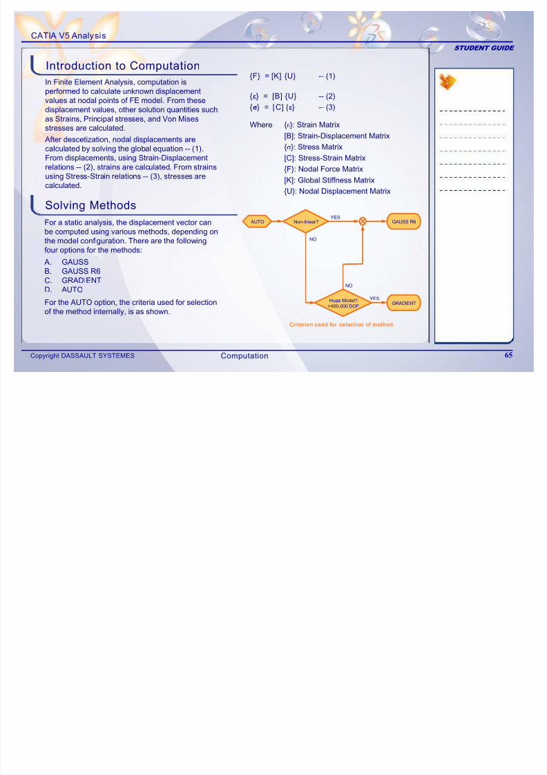
In Finite Element Analysis, computation isperformed to calculate unknown displacementvalues at nodal points of FE model. From thesedisplacement values, other solution quantities suchas Strains, Principal stresses, and Von Misesstresses are calculated.
Solving Methods
For a static analysis, the displacement vector canbe computed using various methods, depending onthe model configuration. There are the followingfour options for the methods:
Introduction to Computation
After descetization, nodal displacements arecalculated by solving the global equation -- (1).From displacements, using Strain-Displacementrelations -- (2), strains are calculated. From strainsusing Stress-Strain relations -- (3), stresses arecalculated.
{F} = [K] {U} -- (1)
{ε} = [B] {U} -- (2)
{σ} = [C] {ε} -- (3)
Where {ε}: Strain Matrix
[B]: Strain-Displacement Matrix
{σ}: Stress Matrix[C]: Stress-Strain Matrix
{F}: Nodal Force Matrix
[K]: Global Stiffness Matrix
{U}: Nodal Displacement Matrix
A. GAUSSB. GAUSS R6
C. GRADIENTD. AUTO
Criterion used for selection of method.
YES
AUTO Non-linear?
Huge Model?>400,000 DOF
GAUSS R6
GRADIENT
YES
NO
NO
For the AUTO option, the criteria used for selectionof the method internally, is as shown.
Computation
CATIA V5 Analysis
STUDENT GUIDE
C ti St ti C
7/16/2019 Edu Cat en v5a Fb v5r19
http://slidepdf.com/reader/full/edu-cat-en-v5a-fb-v5r19 66/172
Copyright DASSAULT SYSTEMES 66
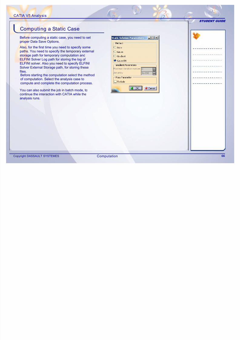
Before computing a static case, you need to setproper Data Save Options.
Computing a Static Case
Also, for the first time you need to specify somepaths. You need to specify the temporary externalstorage path for temporary computation andELFINI Solver Log path for storing the log of
ELFINI solver. Also you need to specify ELFINISolver External Storage path, for storing thesefiles.Before starting the computation select the methodof computation. Select the analysis case tocompute and complete the computation process.
You can also submit the job in batch mode, to
continue the interaction with CATIA while theanalysis runs.
Computation
CATIA V5 Analysis
STUDENT GUIDE
M i T l
7/16/2019 Edu Cat en v5a Fb v5r19
http://slidepdf.com/reader/full/edu-cat-en-v5a-fb-v5r19 67/172
Copyright DASSAULT SYSTEMES 67
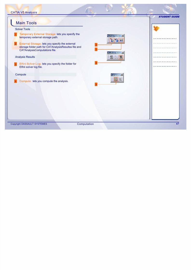
Solver Tools
1
Main Tools
1
2
3
4
Analysis Results
Temporary External Storage: lets you specify thetemporary external storage path.
External Storage: lets you specify the externalstorage folder path for CATAnalysisResultss file and
CATAnalysisComputations file.
Elfini Solver Log: lets you specify the folder forElfini solver log file.
2
4
3
Compute
Compute: lets you compute the analysis.
Computation
CATIA V5 Analysis
STUDENT GUIDE
E i 3B
7/16/2019 Edu Cat en v5a Fb v5r19
http://slidepdf.com/reader/full/edu-cat-en-v5a-fb-v5r19 68/172
Copyright DASSAULT SYSTEMES 68
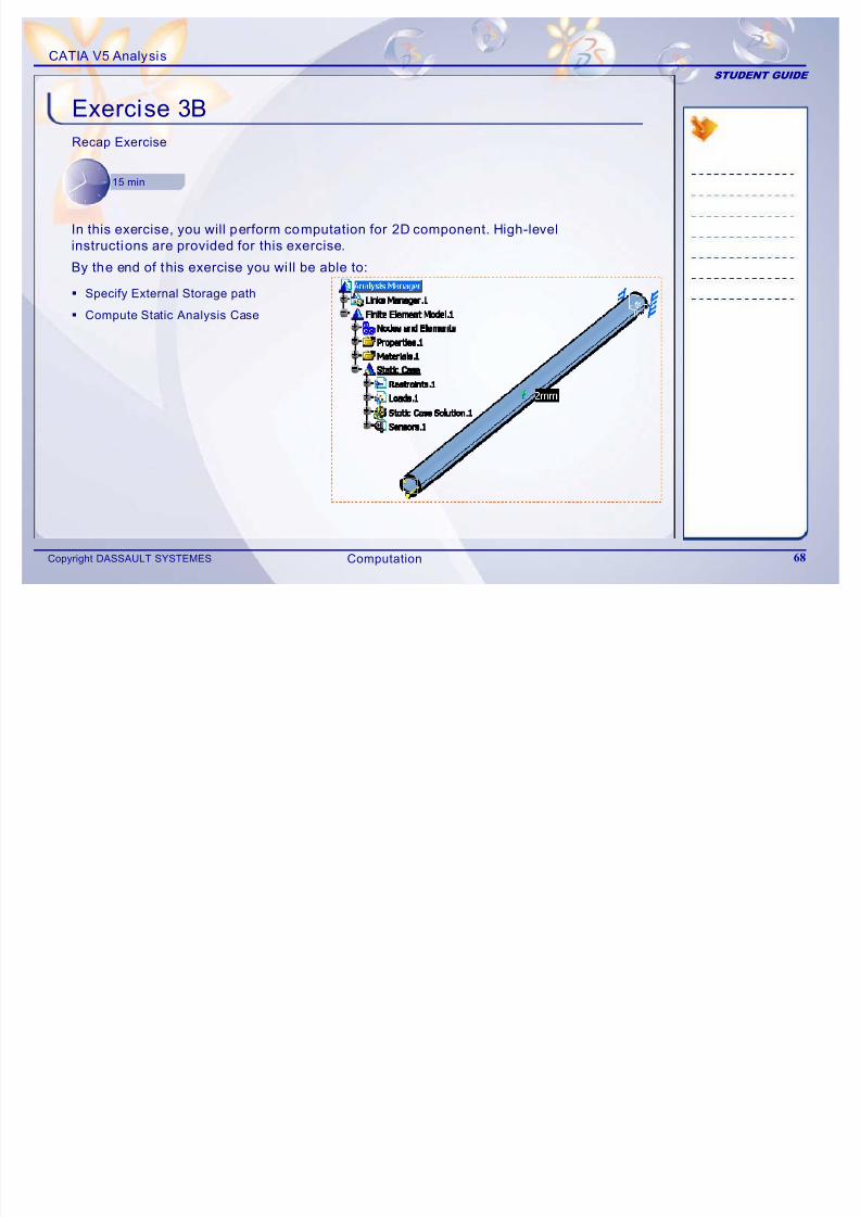
Exercise 3B
Recap Exercise
15 min
In this exercise, you will perform computation for 2D component. High-levelinstructions are provided for this exercise.
By the end of this exercise you wi ll be able to:
Specify External Storage path
Compute Static Analysis Case
Computation
CATIA V5 Analysis
STUDENT GUIDE
Exercise 3B (1/2)
7/16/2019 Edu Cat en v5a Fb v5r19
http://slidepdf.com/reader/full/edu-cat-en-v5a-fb-v5r19 69/172
Copyright DASSAULT SYSTEMES 69
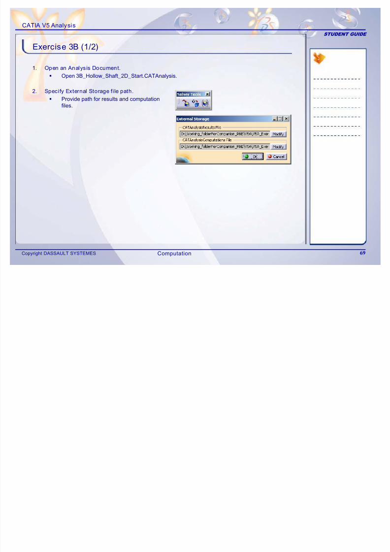
Exercise 3B (1/2)
1. Open an Analysis Document.
Open 3B_Hollow_Shaft_2D_Start.CATAnalysis.
2. Specify External Storage fi le path.
Provide path for results and computation
files.
Computation
CATIA V5 Analysis
STUDENT GUIDE
Exercise 3B (2/2)
7/16/2019 Edu Cat en v5a Fb v5r19
http://slidepdf.com/reader/full/edu-cat-en-v5a-fb-v5r19 70/172
Copyright DASSAULT SYSTEMES 70
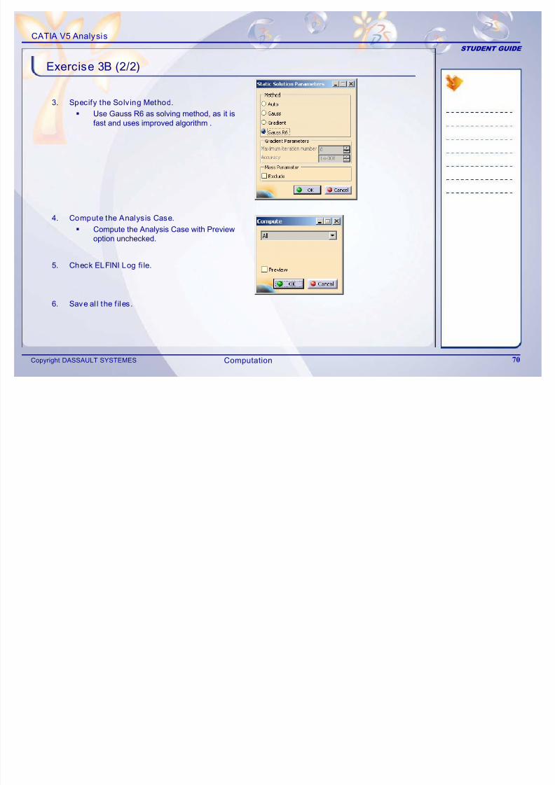
Exercise 3B (2/2)
3. Specify the Solving Method.
Use Gauss R6 as solving method, as it isfast and uses improved algorithm .
4. Compute the Analysis Case.
Compute the Analysis Case with Previewoption unchecked.
5. Check ELFINI Log fi le.
6. Save al l the f iles.
Computation
CATIA V5 Analysis
STUDENT GUIDE
Exercise 3B: Recap
7/16/2019 Edu Cat en v5a Fb v5r19
http://slidepdf.com/reader/full/edu-cat-en-v5a-fb-v5r19 71/172
Copyright DASSAULT SYSTEMES 71
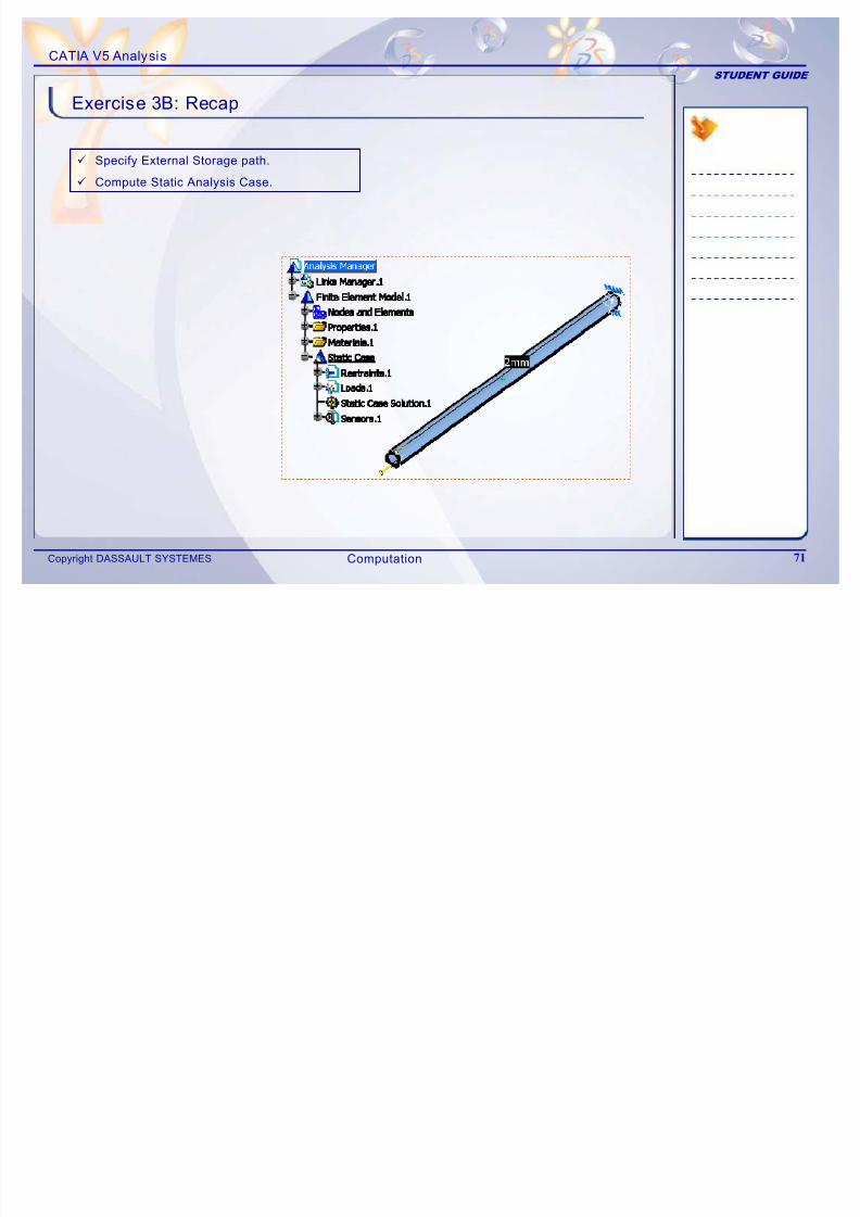
Exercise 3B: Recap
9 Specify External Storage path.
9 Compute Static Analysis Case.
Computation
CATIA V5 Analysis
STUDENT GUIDE
Exercise 3C
7/16/2019 Edu Cat en v5a Fb v5r19
http://slidepdf.com/reader/full/edu-cat-en-v5a-fb-v5r19 72/172
Copyright DASSAULT SYSTEMES 72
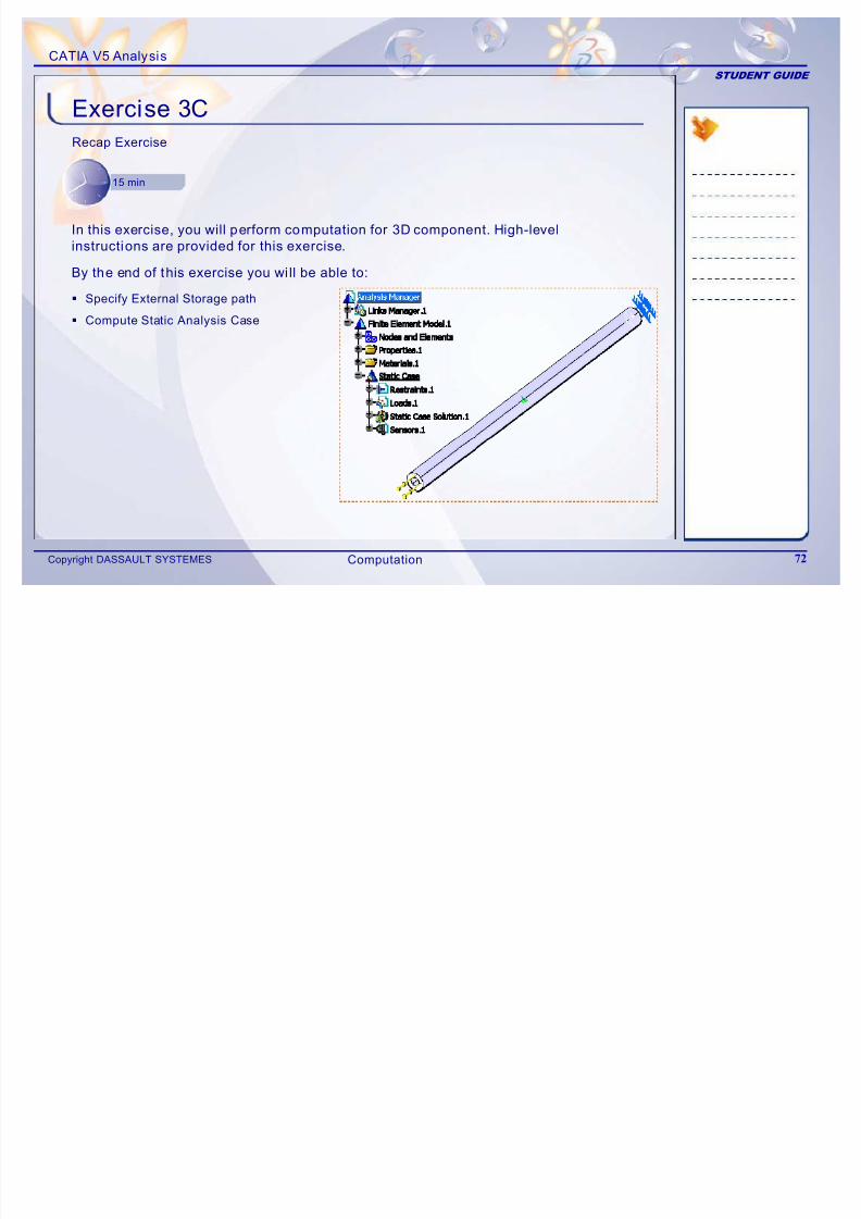
Exercise 3C
Recap Exercise
15 min
In this exercise, you will perform computation for 3D component. High-levelinstructions are provided for this exercise.
By the end of this exercise you wi ll be able to:
Specify External Storage path
Compute Static Analysis Case
Computation
CATIA V5 Analysis
STUDENT GUIDE
Exercise 3C (1/2)
7/16/2019 Edu Cat en v5a Fb v5r19
http://slidepdf.com/reader/full/edu-cat-en-v5a-fb-v5r19 73/172
Copyright DASSAULT SYSTEMES 73
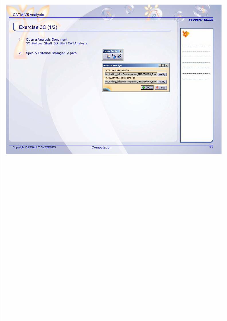
Exercise 3C (1/2)
1. Open a Analysis Document
3C_Hollow_Shaft_3D_Start.CATAnalysis.
2. Specify External Storage fi le path.
Computation
CATIA V5 Analysis
STUDENT GUIDE
Exercise 3C (2/2)
7/16/2019 Edu Cat en v5a Fb v5r19
http://slidepdf.com/reader/full/edu-cat-en-v5a-fb-v5r19 74/172
Copyright DASSAULT SYSTEMES 74
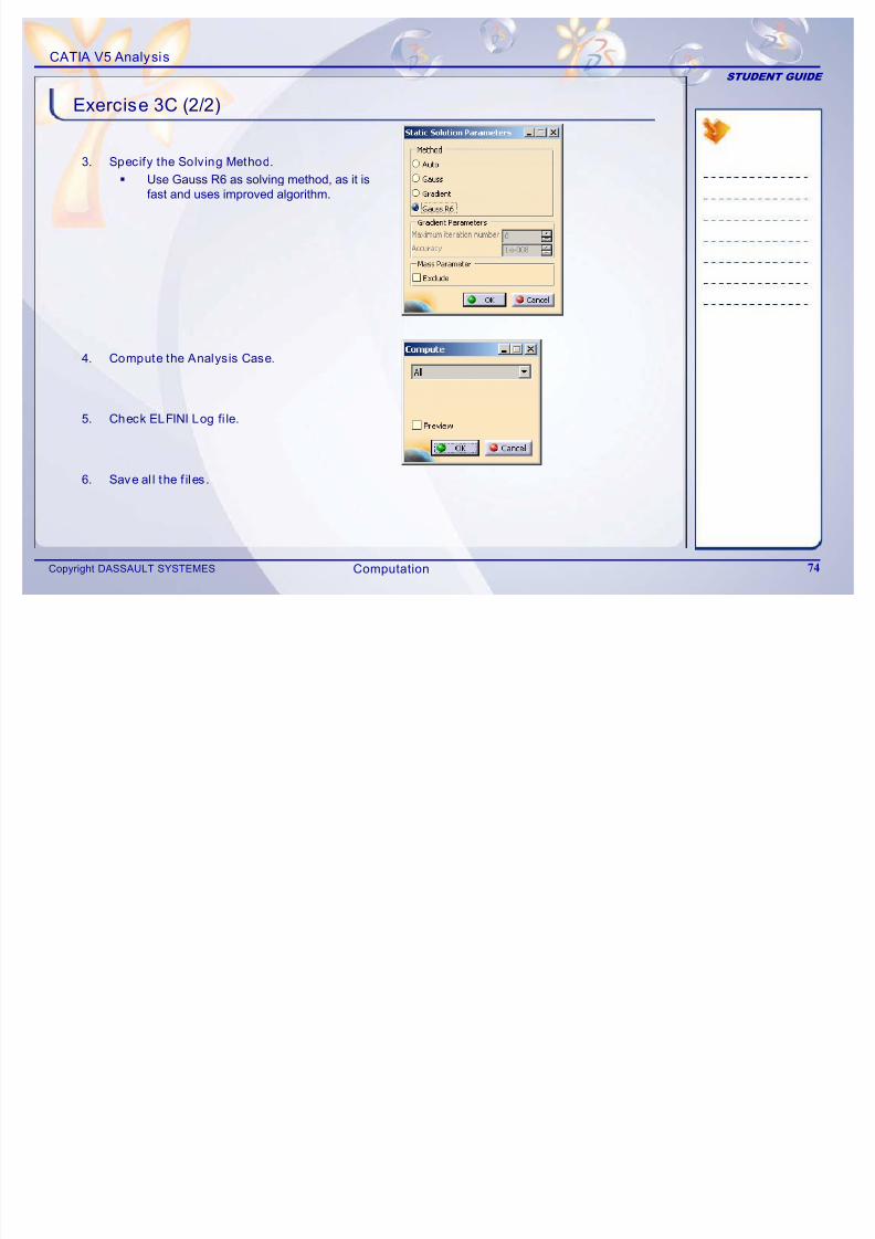
( )
3. Specify the Solving Method.
Use Gauss R6 as solving method, as it isfast and uses improved algorithm.
4. Compute the Analysis Case.
5. Check ELFINI Log fi le.
6. Save al l the f iles.
Computation
CATIA V5 Analysis
STUDENT GUIDE
Exercise 3C: Recap
7/16/2019 Edu Cat en v5a Fb v5r19
http://slidepdf.com/reader/full/edu-cat-en-v5a-fb-v5r19 75/172
Copyright DASSAULT SYSTEMES 75
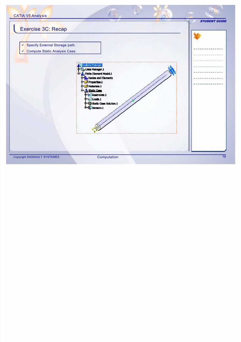
p
9 Specify External Storage path.
9 Compute Static Analysis Case.
Computation
CATIA V5 Analysis
STUDENT GUIDE
Case Study: Computing Dril l Press Table
7/16/2019 Edu Cat en v5a Fb v5r19
http://slidepdf.com/reader/full/edu-cat-en-v5a-fb-v5r19 76/172
Copyright DASSAULT SYSTEMES 76
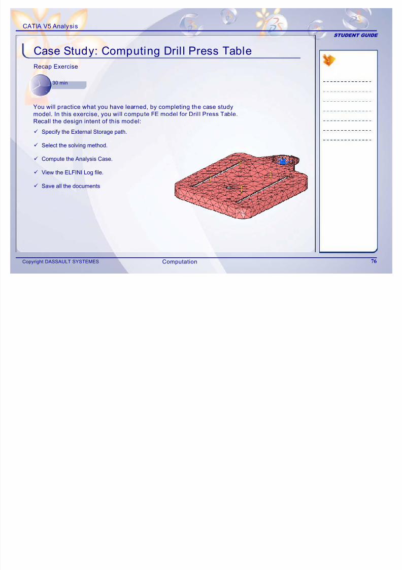
Case Study: Computing Dril l Press Table
Recap Exercise
30 min
You will practice what you have learned, by completing the case studymodel. In this exercise, you wi ll compute FE model for Dril l Press Table.
Recall the design intent of th is model:
9 Specify the External Storage path.
9 Select the solving method.
9 Compute the Analysis Case.
9 View the ELFINI Log file.
9 Save all the documents
Computation
CATIA V5 Analysis
STUDENT GUIDE
Case Study: Introduction
7/16/2019 Edu Cat en v5a Fb v5r19
http://slidepdf.com/reader/full/edu-cat-en-v5a-fb-v5r19 77/172
Copyright DASSAULT SYSTEMES 77
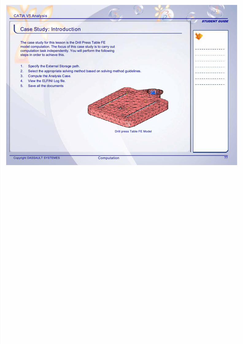
The case study for this lesson is the Drill Press Table FEmodel computation. The focus of this case study is to carry outcomputation task independently. You will perform the followingsteps in order to achieve this.
Drill press Table FE Model
1. Specify the External Storage path.2. Select the appropriate solving method based on solving method guidelines.
3. Compute the Analysis Case.
4. View the ELFINI Log file.
5. Save all the documents
Computation
CATIA V5 Analysis
STUDENT GUIDE
Design Intent
7/16/2019 Edu Cat en v5a Fb v5r19
http://slidepdf.com/reader/full/edu-cat-en-v5a-fb-v5r19 78/172
Copyright DASSAULT SYSTEMES 78
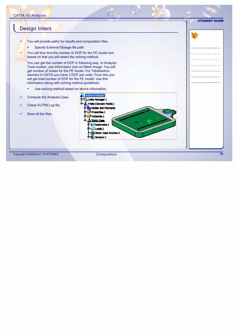
9 You will provide paths for results and computation files.
Specify External Storage file path
9 You will then find the number of DOF for the FE model andbased on that you will select the solving method.
You can get the number of DOF in following way. In Analysis Tools toolbar, use information icon on Mesh Image. You willget number of nodes for the FE model. For Tetrahedronelement in CATIA you have 3 DOF per node. From this youwill get total number of DOF for the FE model. Use thisinformation along with solving method guidelines.
Use solving method based on above information.
9 Compute the Analysis Case.
9 Check ELFINI Log file.
9 Save all the files.
Computation
CATIA V5 Analysis
STUDENT GUIDE
Do It Yourself
7/16/2019 Edu Cat en v5a Fb v5r19
http://slidepdf.com/reader/full/edu-cat-en-v5a-fb-v5r19 79/172
Copyright DASSAULT SYSTEMES 79
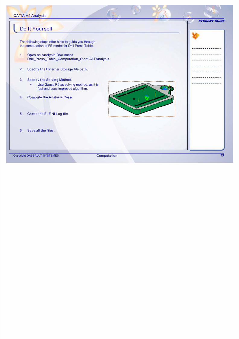
The following steps offer hints to guide you throughthe computation of FE model for Drill Press Table.
1. Open an Analysis Document
Drill_Press_Table_Computation_Start.CATAnalysis.
2. Specify the External Storage fi le path.
3. Specify the Solving Method.
Use Gauss R6 as solving method, as it isfast and uses improved algorithm.
4. Compute the Analysis Case.
5. Check the ELFINI Log fi le.
6. Save al l the f iles.
Computation
CATIA V5 Analysis
STUDENT GUIDE
Case Study: Computing Dril l Press Table Model Recap
7/16/2019 Edu Cat en v5a Fb v5r19
http://slidepdf.com/reader/full/edu-cat-en-v5a-fb-v5r19 80/172
Copyright DASSAULT SYSTEMES 80
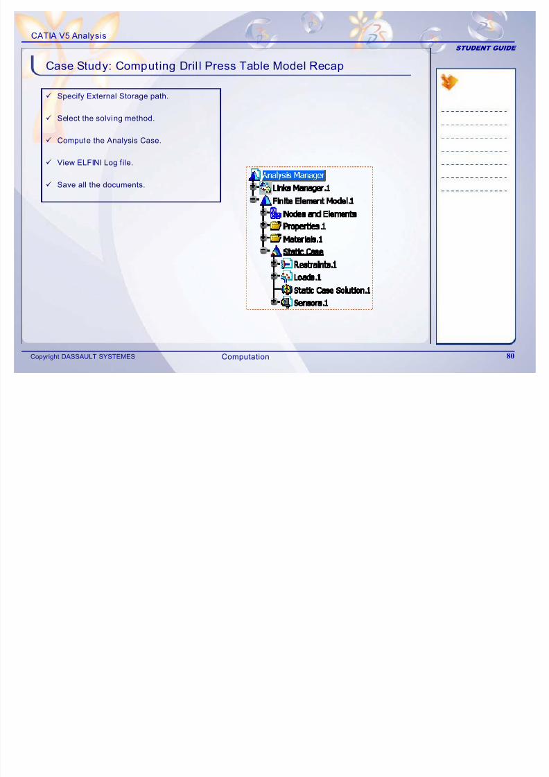
9 Specify External Storage path.
9 Select the solving method.
9 Compute the Analysis Case.
9 View ELFINI Log f ile.
9 Save all the documents.
Computation
CATIA V5 Analysis
STUDENT GUIDE
4Post-processing
7/16/2019 Edu Cat en v5a Fb v5r19
http://slidepdf.com/reader/full/edu-cat-en-v5a-fb-v5r19 81/172
Copyright DASSAULT SYSTEMES 81
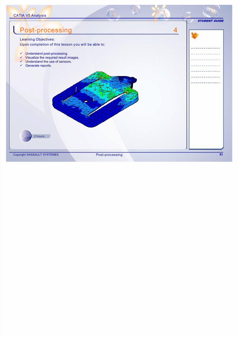
9 Understand post-processing.9 Visualize the required result images.9 Understand the use of sensors.
9 Generate reports.
p g
Learning Objectives:
Upon completion of this lesson you will be able to:
2 hours
Post-processing
CATIA V5 Analysis
STUDENT GUIDE
Case Study
7/16/2019 Edu Cat en v5a Fb v5r19
http://slidepdf.com/reader/full/edu-cat-en-v5a-fb-v5r19 82/172
Copyright DASSAULT SYSTEMES 82
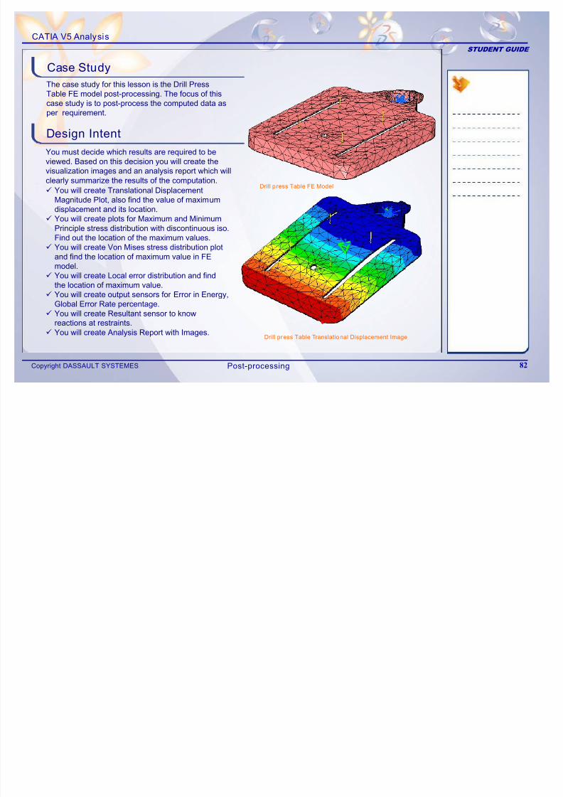
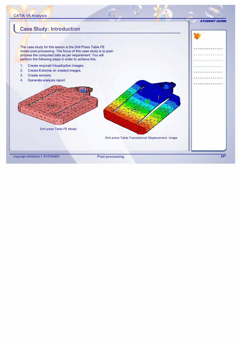
The case study for this lesson is the Drill Press Table FE model post-processing. The focus of thiscase study is to post-process the computed data asper requirement.
Design Intent
You must decide which results are required to beviewed. Based on this decision you will create thevisualization images and an analysis report which willclearly summarize the results of the computation.
9 You will create Translational DisplacementMagnitude Plot, also find the value of maximumdisplacement and its location.
9 You will create plots for Maximum and MinimumPrinciple stress distribution with discontinuous iso.Find out the location of the maximum values.
9 You will create Von Mises stress distribution plotand find the location of maximum value in FEmodel.
9 You will create Local error distribution and findthe location of maximum value.
9 You will create output sensors for Error in Energy,Global Error Rate percentage.
9 You will create Resultant sensor to knowreactions at restraints.
9 You will create Analysis Report with Images.Drill press Table Translational Displacement Image
Drill p ress Table FE Model
Post-processing
CATIA V5 Analysis
STUDENT GUIDE
Stages in the Process
7/16/2019 Edu Cat en v5a Fb v5r19
http://slidepdf.com/reader/full/edu-cat-en-v5a-fb-v5r19 83/172
Copyright DASSAULT SYSTEMES 83
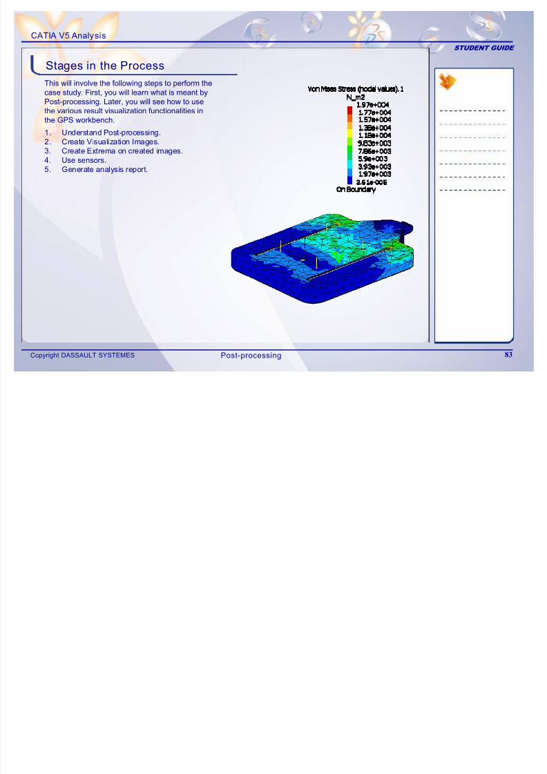
This will involve the following steps to perform thecase study. First, you will learn what is meant byPost-processing. Later, you will see how to usethe various result visualization functionalities inthe GPS workbench.
1. Understand Post-processing.2. Create Visualization Images.
3. Create Extrema on created images.4. Use sensors.5. Generate analysis report.
Post-processing
CATIA V5 Analysis
STUDENT GUIDE
What is Post-processing
7/16/2019 Edu Cat en v5a Fb v5r19
http://slidepdf.com/reader/full/edu-cat-en-v5a-fb-v5r19 84/172
Copyright DASSAULT SYSTEMES 84
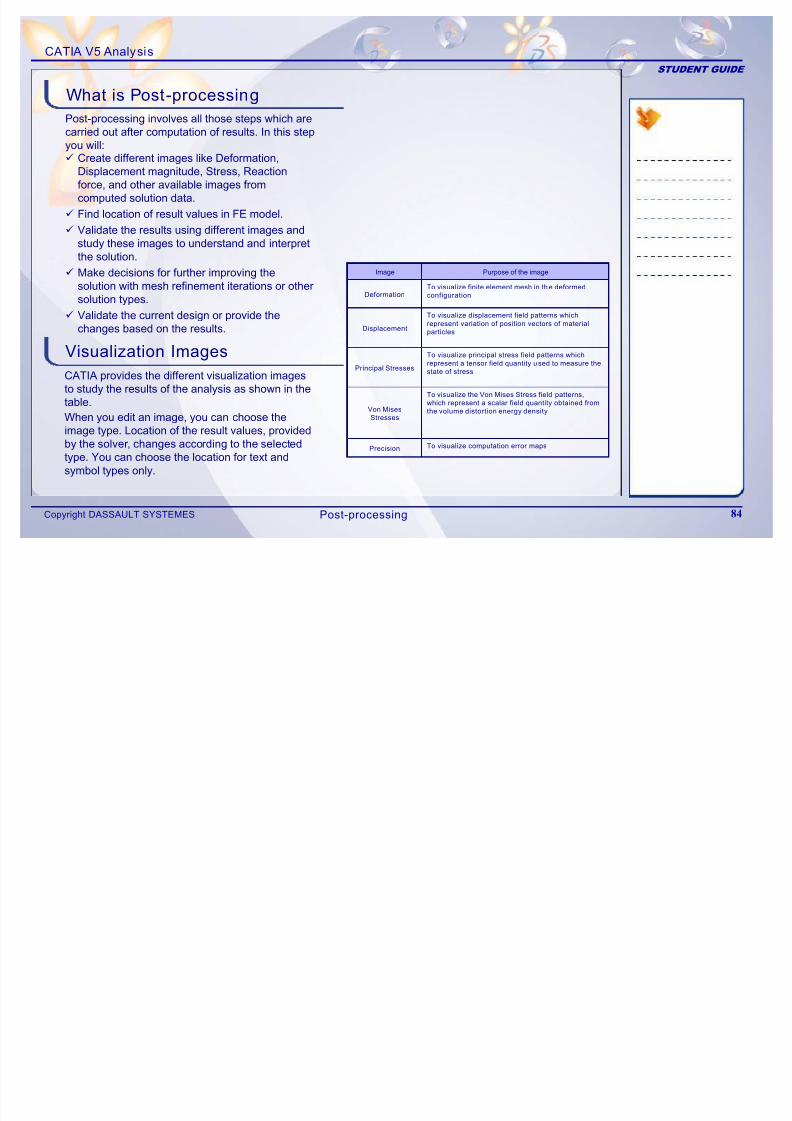
Post-processing involves all those steps which arecarried out after computation of results. In this stepyou will:9 Create different images like Deformation,
Displacement magnitude, Stress, Reactionforce, and other available images fromcomputed solution data.
9 Find location of result values in FE model.9 Validate the results using different images and
study these images to understand and interpretthe solution.
9 Make decisions for further improving thesolution with mesh refinement iterations or othersolution types.
9 Validate the current design or provide thechanges based on the results.
Visualization Images
CATIA provides the different visualization imagesto study the results of the analysis as shown in thetable.
When you edit an image, you can choose theimage type. Location of the result values, providedby the solver, changes according to the selectedtype. You can choose the location for text andsymbol types only.
To visualize the Von Mises Stress field patterns,
which represent a scalar field quantity obtained from
the volume distortion energy densityVon MisesStresses
To visualize computation error mapsPrecision
To visualize principal stress field patterns which
represent a tensor field quantity used to measure the
state of stressPrincipal Stresses
To visualize displacement field patterns whichrepresent variation of position vectors of material
particles
To visualize finite element mesh in the deformed
configuration
Purpose of the image
Displacement
Deformation
Image
Post-processing
CATIA V5 Analysis
STUDENT GUIDE
Sensors
7/16/2019 Edu Cat en v5a Fb v5r19
http://slidepdf.com/reader/full/edu-cat-en-v5a-fb-v5r19 85/172
Copyright DASSAULT SYSTEMES 85
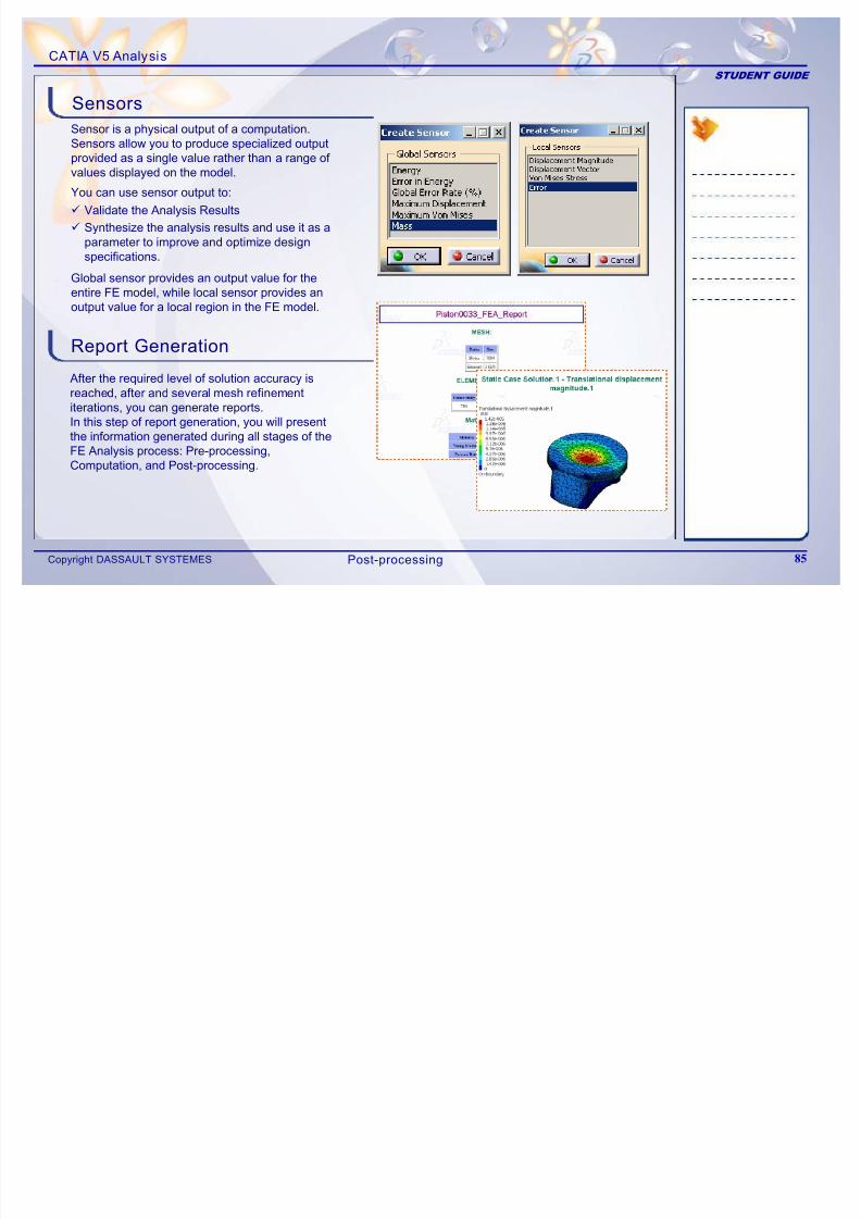
Report Generation
After the required level of solution accuracy isreached, after and several mesh refinementiterations, you can generate reports.In this step of report generation, you will presentthe information generated during all stages of the
FE Analysis process: Pre-processing,Computation, and Post-processing.
Global sensor provides an output value for theentire FE model, while local sensor provides anoutput value for a local region in the FE model.
9 Validate the Analysis Results
9
Synthesize the analysis results and use it as aparameter to improve and optimize designspecifications.
Sensor is a physical output of a computation.Sensors allow you to produce specialized outputprovided as a single value rather than a range of values displayed on the model.
You can use sensor output to:
Post-processing
CATIA V5 Analysis
STUDENT GUIDE
Main Tools (1/2)
7/16/2019 Edu Cat en v5a Fb v5r19
http://slidepdf.com/reader/full/edu-cat-en-v5a-fb-v5r19 86/172
Copyright DASSAULT SYSTEMES 86
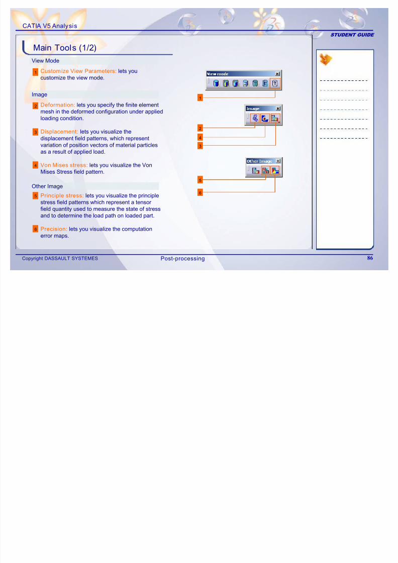
View Mode
1
1
2
3
4
Image
5
Customize View Parameters: lets youcustomize the view mode.
6
6
5
2
3
4
Other Image
Deformation: lets you specify the finite elementmesh in the deformed configuration under appliedloading condition.
Displacement: lets you visualize thedisplacement field patterns, which representvariation of position vectors of material particlesas a result of applied load.
Von Mises stress: lets you visualize the VonMises Stress field pattern.
Principle stress: lets you visualize the principlestress field patterns which represent a tensorfield quantity used to measure the state of stressand to determine the load path on loaded part.
Precision: lets you visualize the computationerror maps.
Post-processing
CATIA V5 Analysis
STUDENT GUIDE
A l i t l
Main Tools (2/2)
7/16/2019 Edu Cat en v5a Fb v5r19
http://slidepdf.com/reader/full/edu-cat-en-v5a-fb-v5r19 87/172
Copyright DASSAULT SYSTEMES 87
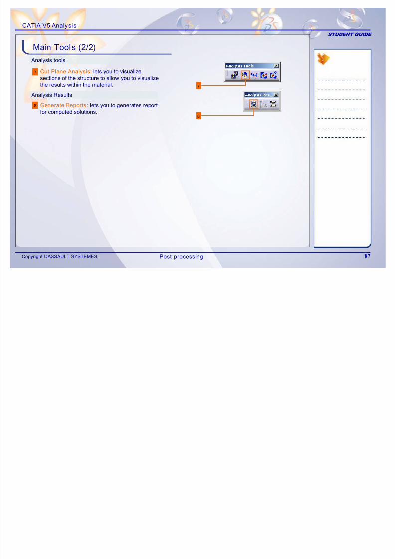
Analysis tools
Cut Plane Analysis: lets you to visualizesections of the structure to allow you to visualizethe results within the material.
7
8
7
8
Generate Reports: lets you to generates reportfor computed solutions.
Analysis Results
Post-processing
CATIA V5 Analysis
STUDENT GUIDE
Exercise 4B

7/16/2019 Edu Cat en v5a Fb v5r19
http://slidepdf.com/reader/full/edu-cat-en-v5a-fb-v5r19 88/172
Copyright DASSAULT SYSTEMES 88
Recap Exercise
15 min
In this exercise, you wi ll create result visualization images for 2D component.
Detailed ins tructions for new topics are provided for this exercise.
By the end of this exercise you wi ll be able to:
Create Translational Displacement image
Create Principal Stress Image
Create Von Mises Stress Image
Create Precision Image
Create Energy and Global error Rate sensor
Animate the d isplacement Image
Post-processing
CATIA V5 Analysis
STUDENT GUIDE
Exercise 4B (1/7)
7/16/2019 Edu Cat en v5a Fb v5r19
http://slidepdf.com/reader/full/edu-cat-en-v5a-fb-v5r19 89/172
Copyright DASSAULT SYSTEMES 89
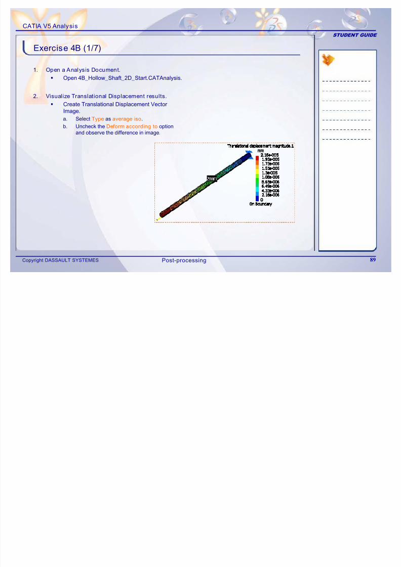
1. Open a Analysis Document.
Open 4B_Hollow_Shaft_2D_Start.CATAnalysis.
2. Visualize Translational Displacement results.
Create Translational Displacement Vector
Image.a. Select Type as average iso.
b. Uncheck the Deform according to optionand observe the difference in image.
Post-processing
CATIA V5 Analysis
STUDENT GUIDE
Exercise 4B (2/7)
7/16/2019 Edu Cat en v5a Fb v5r19
http://slidepdf.com/reader/full/edu-cat-en-v5a-fb-v5r19 90/172
Copyright DASSAULT SYSTEMES 90
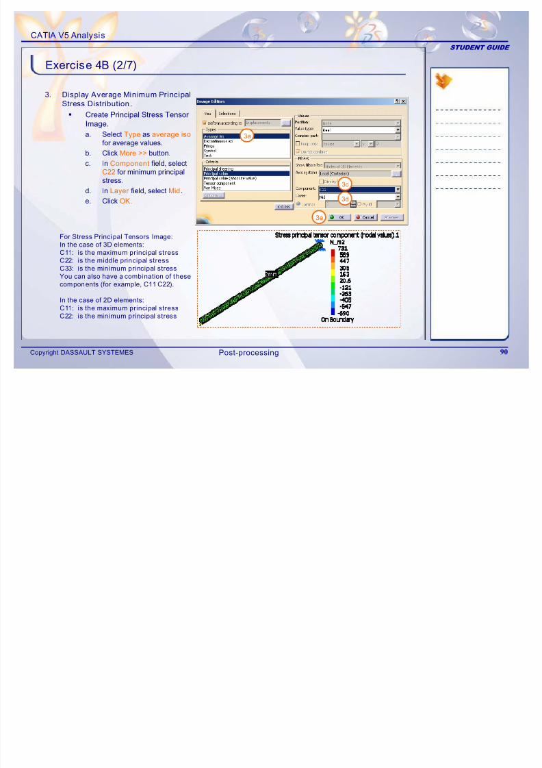
3. Display Average Minimum Principal
Stress Distribution.
Create Principal Stress TensorImage.
a. Select Type as average iso
for average values.
b. Click More >> button.
c. In Component field, selectC22 for minimum principalstress.
d. In Layer field, select Mid.
e. Click OK.
For Stress Principal Tensors Image:
In the case of 3D elements:
C11: is the maximum principal stress
C22: is the middle principal stress
C33: is the minimum principal stress
You can also have a combination of these
components (for example, C11 C22).
In the case of 2D elements:
C11: is the maximum principal stress
C22: is the minimum principal stress
3a
3c
3d
3e
Post-processing
CATIA V5 Analysis
STUDENT GUIDE
Exercise 4B (3/7)
7/16/2019 Edu Cat en v5a Fb v5r19
http://slidepdf.com/reader/full/edu-cat-en-v5a-fb-v5r19 91/172
Copyright DASSAULT SYSTEMES 91
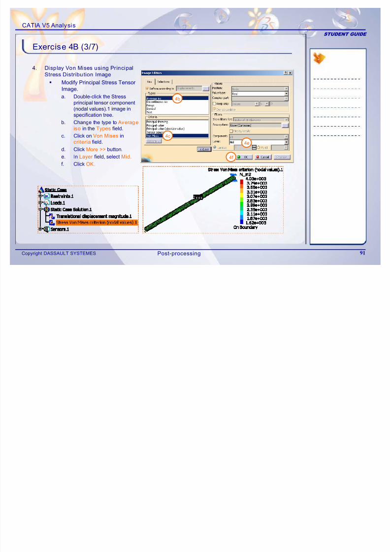
4. Display Von Mises using Principal
Stress Distribution Image
Modify Principal Stress TensorImage.
a. Double-click the Stress
principal tensor component
(nodal values).1 image inspecification tree.
b. Change the type to Average
iso in the Types field.
c. Click on Von Mises incriteria field.
d. Click More >> button.
e. In Layer field, select Mid.
f. Click OK.
4b
4c
4e
4f
Post-processing
CATIA V5 Analysis
STUDENT GUIDE
Exercise 4B (4/7)
7/16/2019 Edu Cat en v5a Fb v5r19
http://slidepdf.com/reader/full/edu-cat-en-v5a-fb-v5r19 92/172
Copyright DASSAULT SYSTEMES 92
5a
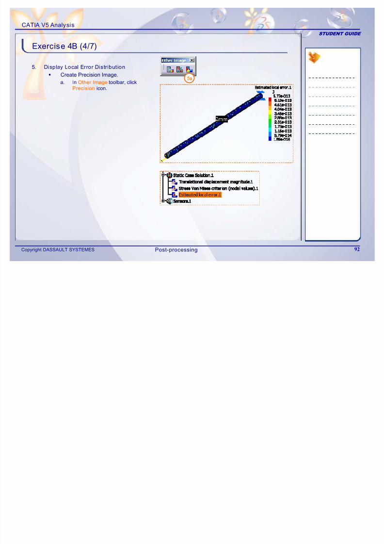
5. Display Local Error Distr ibution
Create Precision Image.
a. In Other Image toolbar, clickPrecision icon.
Post-processing
CATIA V5 Analysis
STUDENT GUIDE
Exercise 4B (5/7)
7/16/2019 Edu Cat en v5a Fb v5r19
http://slidepdf.com/reader/full/edu-cat-en-v5a-fb-v5r19 93/172
Copyright DASSAULT SYSTEMES 93
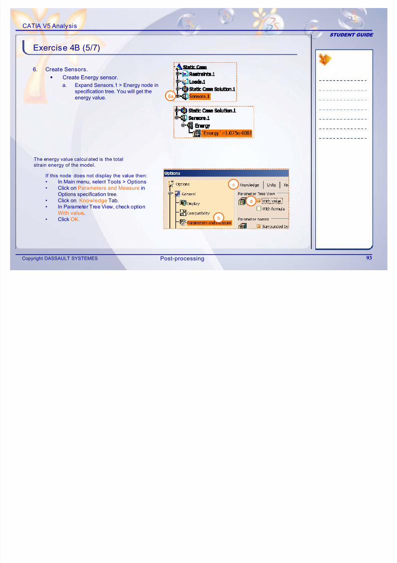
6. Create Sensors.
Create Energy sensor.
a. Expand Sensors.1 >Energy node inspecification tree. You will get theenergy value. 6a
b
c
d
If this node does not display the value then:
• In Main menu, select Tools > Options
• Click on Parameters and Measure inOptions specification tree.
• Click on Knowledge Tab.
• In Parameter Tree View, check optionWith value.
• Click OK.
The energy value calculated is the totalstrain energy of the model.
Post-processing
CATIA V5 Analysis
STUDENT GUIDE
Exercise 4B (6/7)
7/16/2019 Edu Cat en v5a Fb v5r19
http://slidepdf.com/reader/full/edu-cat-en-v5a-fb-v5r19 94/172
Copyright DASSAULT SYSTEMES 94
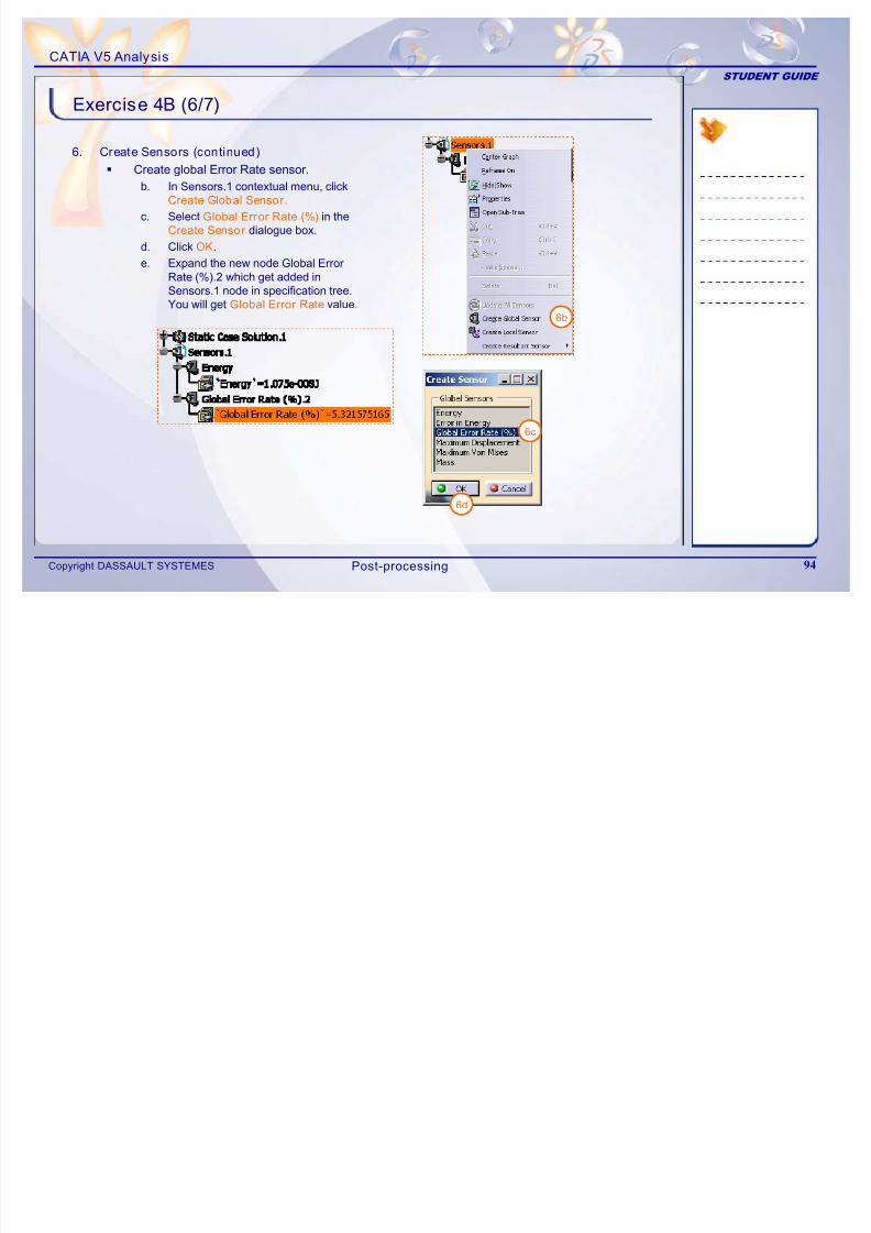
6. Create Sensors (continued)
Create global Error Rate sensor.
b. In Sensors.1 contextual menu, clickCreate Global Sensor .
c. Select Global Error Rate (%) in theCreate Sensor dialogue box.
d. Click OK.
e. Expand the new node Global Error
Rate (%).2 which get added inSensors.1 node in specification tree.
You will get Global Error Rate value.6b
6c
6d
Post-processing
CATIA V5 Analysis
STUDENT GUIDE
Exercise 4B (7/7)
7/16/2019 Edu Cat en v5a Fb v5r19
http://slidepdf.com/reader/full/edu-cat-en-v5a-fb-v5r19 95/172
Copyright DASSAULT SYSTEMES 95
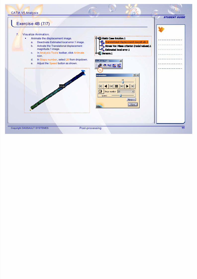
7. Visual ize Animat ion.
Animate the displacement image.
a. Deactivate Estimated local error.1 image.
b. Activate the Translational displacement
magnitude.1 image.
c. In Analysis Tools toolbar, click Animate
icon.
d. In Steps number , select 20 from dropdown.
e. Adjust the Speed button as shown.
7c
Post-processing
CATIA V5 Analysis
STUDENT GUIDE
Exercise 4B: Recap
7/16/2019 Edu Cat en v5a Fb v5r19
http://slidepdf.com/reader/full/edu-cat-en-v5a-fb-v5r19 96/172
Copyright DASSAULT SYSTEMES 96
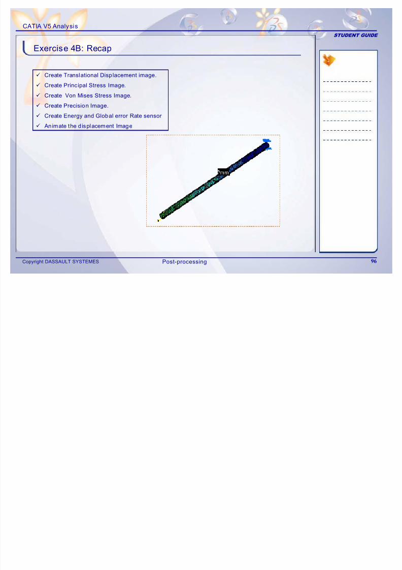
9 Create Translational Displacement image.
9 Create Principal Stress Image.
9 Create Von Mises Stress Image.
9 Create Precision Image.
9 Create Energy and Global error Rate sensor
9 Animate the d isplacement Image
Post-processing
CATIA V5 Analysis
STUDENT GUIDE
Exercise 4C
Recap Exercise
7/16/2019 Edu Cat en v5a Fb v5r19
http://slidepdf.com/reader/full/edu-cat-en-v5a-fb-v5r19 97/172
Copyright DASSAULT SYSTEMES 97
Recap Exercise
15 min
In this exercise, you wi ll create result visualization images for 3D component.
Detailed ins tructions for new topics are provided for this exercise.
By the end of this exercise you wi ll be able to:
Create Translational Displacement image
Create Von Mises Stress Image
Create Precision Image
Create Global error Rate sensor
Use Cut Plane Analys is
Find Image Extrema
Display Image Information
Generate Report
Post-processing
CATIA V5 Analysis
STUDENT GUIDE
Exercise 4C (1/7)
1 O A l i D t
7/16/2019 Edu Cat en v5a Fb v5r19
http://slidepdf.com/reader/full/edu-cat-en-v5a-fb-v5r19 98/172
Copyright DASSAULT SYSTEMES 98
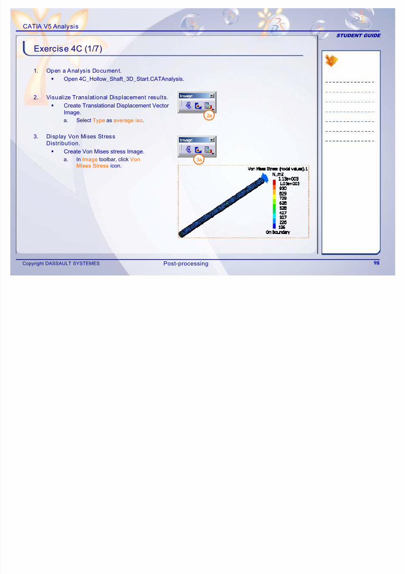
1. Open a Analysis Document.
Open 4C_Hollow_Shaft_3D_Start.CATAnalysis.
2. Visualize Translational Displacement results.
Create Translational Displacement Vector
Image.a. Select Type as average iso.
3. Display Von Mises Stress
Distribution.
Create Von Mises stress Image.
a. In Image toolbar, click VonMises Stress icon. 3a
2a
Post-processing
CATIA V5 Analysis
STUDENT GUIDE
Exercise 4C (2/7)
4 Display Local Error Distr ibution
7/16/2019 Edu Cat en v5a Fb v5r19
http://slidepdf.com/reader/full/edu-cat-en-v5a-fb-v5r19 99/172
Copyright DASSAULT SYSTEMES 99
4a
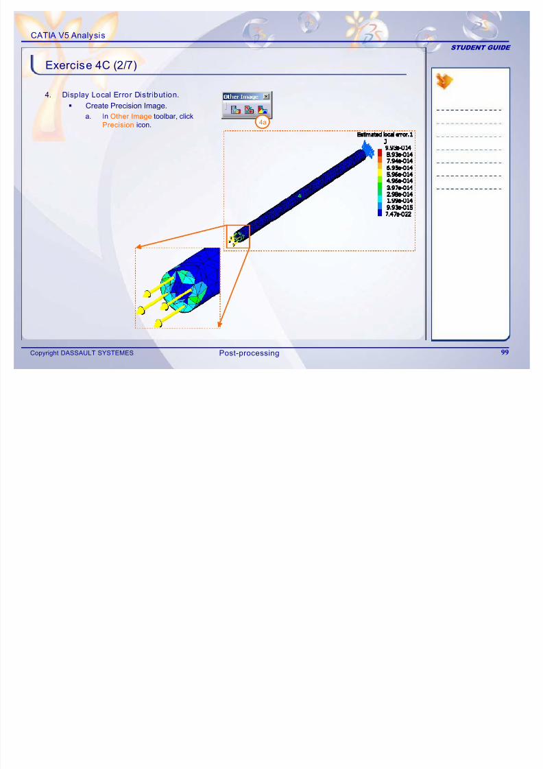
4. Display Local Error Distr ibution.
Create Precision Image.
a. In Other Image toolbar, clickPrecision icon.
Post-processing
CATIA V5 Analysis
STUDENT GUIDE
Exercise 4C (3/7)
5 Create Sensors
7/16/2019 Edu Cat en v5a Fb v5r19
http://slidepdf.com/reader/full/edu-cat-en-v5a-fb-v5r19 100/172
Copyright DASSAULT SYSTEMES 100
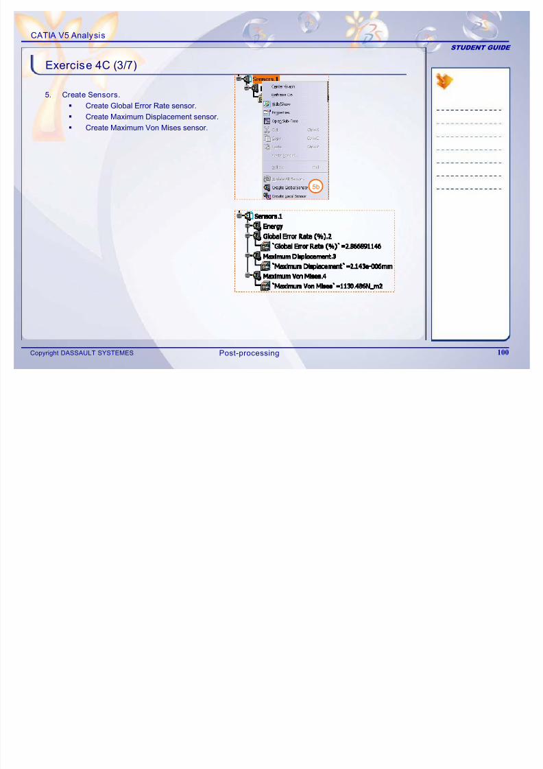
5. Create Sensors.
Create Global Error Rate sensor.
Create Maximum Displacement sensor.
Create Maximum Von Mises sensor.
5b
Post-processing
CATIA V5 Analysis
STUDENT GUIDE
Exercise 4C (4/7)
6 Cut Plane Analys is
7/16/2019 Edu Cat en v5a Fb v5r19
http://slidepdf.com/reader/full/edu-cat-en-v5a-fb-v5r19 101/172
Copyright DASSAULT SYSTEMES 101
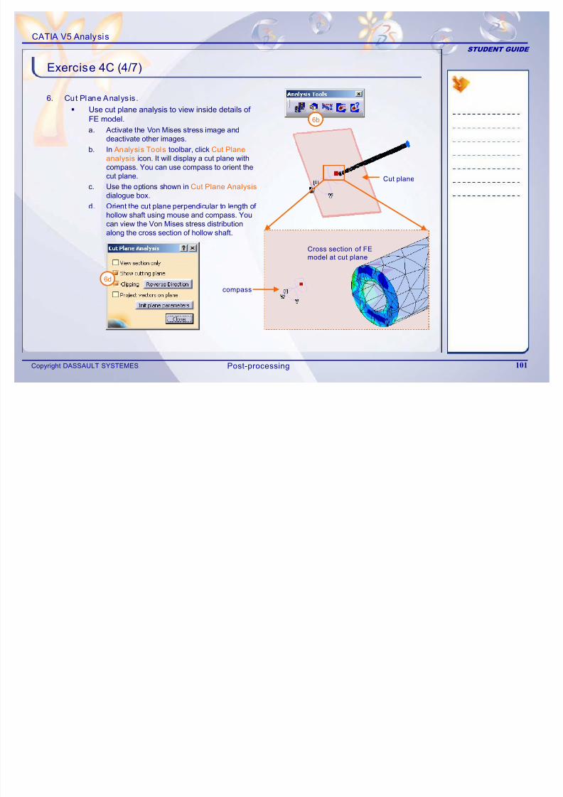
6. Cut Plane Analys is .
Use cut plane analysis to view inside details of FE model.
a. Activate the Von Mises stress image anddeactivate other images.
b. In Analysis Tools toolbar, click Cut Plane
analysis icon. It will display a cut plane withcompass. You can use compass to orient thecut plane.
c. Use the options shown in Cut Plane Analysis
dialogue box.
d. Orient the cut plane perpendicular to length of hollow shaft using mouse and compass. You
can view the Von Mises stress distributionalong the cross section of hollow shaft.
6b
Cut plane
compass
Cross section of FE
model at cut plane
6d
Post-processing
CATIA V5 Analysis
STUDENT GUIDE
Exercise 4C (5/7)
7 Find Maximum Von Mises stress value and location
7/16/2019 Edu Cat en v5a Fb v5r19
http://slidepdf.com/reader/full/edu-cat-en-v5a-fb-v5r19 102/172
Copyright DASSAULT SYSTEMES 102
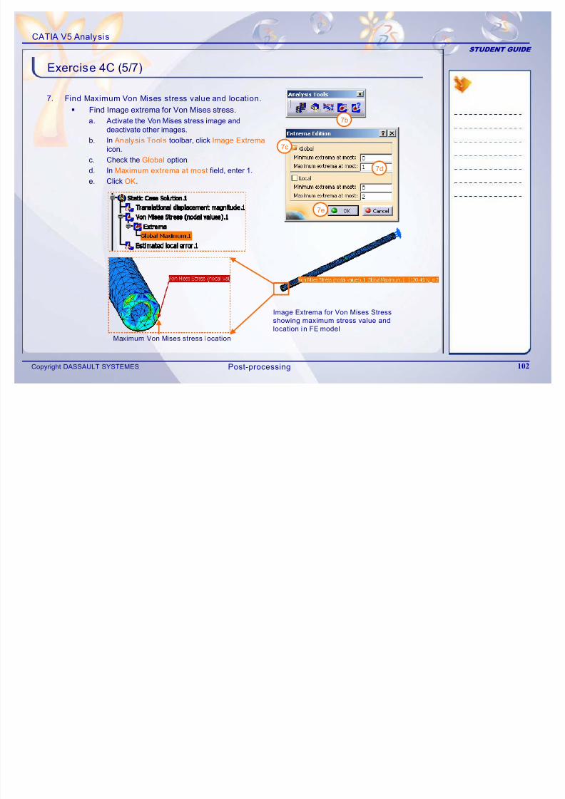
7. Find Maximum Von Mises stress value and location.
Find Image extrema for Von Mises stress.
a. Activate the Von Mises stress image anddeactivate other images.
b. In Analysis Tools toolbar, click Image Extrema
icon.
c. Check the Global option.
d. In Maximum extrema at most field, enter 1.
e. Click OK.
7b
Image Extrema for Von Mises Stress
showing maximum stress value and
location in FE model
Maximum Von Mises stress location
7c
7d
7e
Post-processing
CATIA V5 Analysis
STUDENT GUIDE
Exercise 4C (6/7)
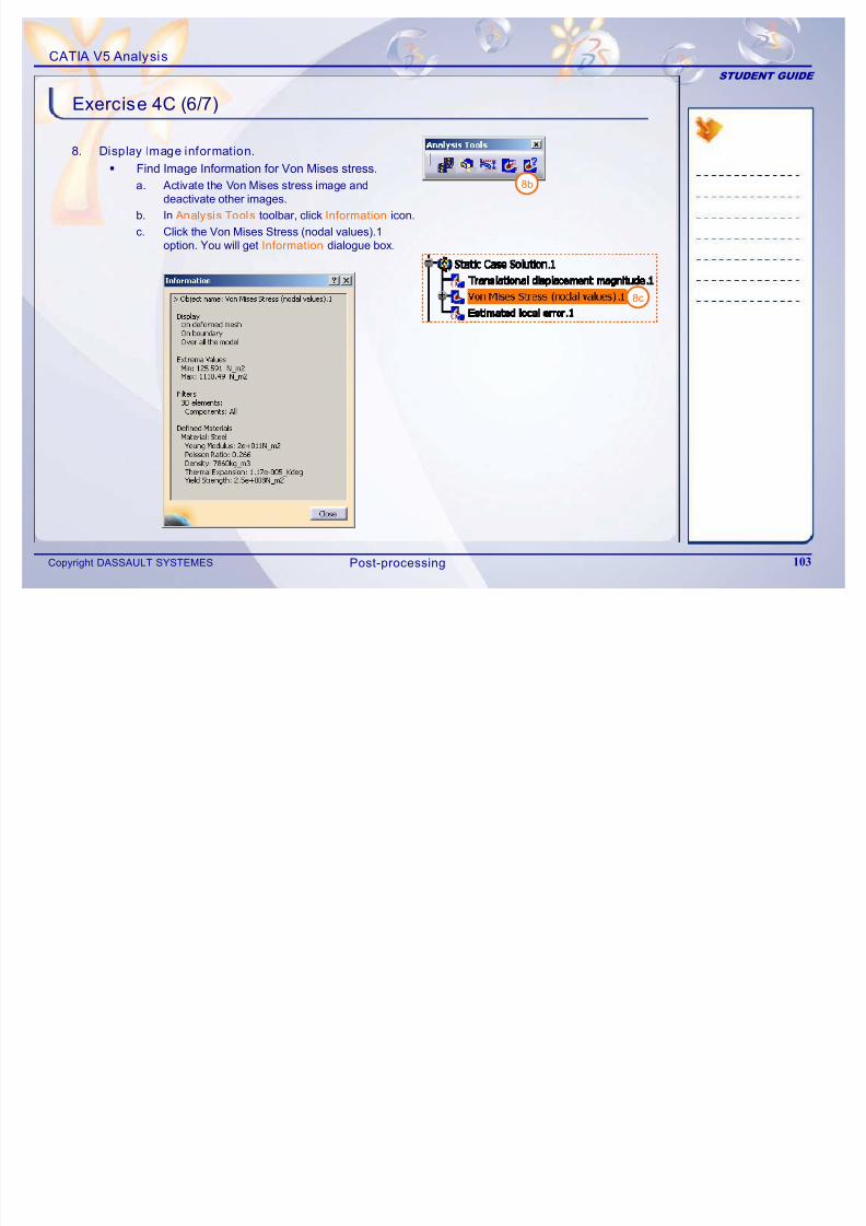
8. Display Image information.
7/16/2019 Edu Cat en v5a Fb v5r19
http://slidepdf.com/reader/full/edu-cat-en-v5a-fb-v5r19 103/172
Copyright DASSAULT SYSTEMES 103
8 sp ay age o at o
Find Image Information for Von Mises stress.
a. Activate the Von Mises stress image anddeactivate other images.
b. In Analysis Tools toolbar, click Information icon.
c. Click the Von Mises Stress (nodal values).1
option. You will get Information dialogue box.
8b
8c
Post-processing
CATIA V5 Analysis
STUDENT GUIDE
Exercise 4C (7/7)
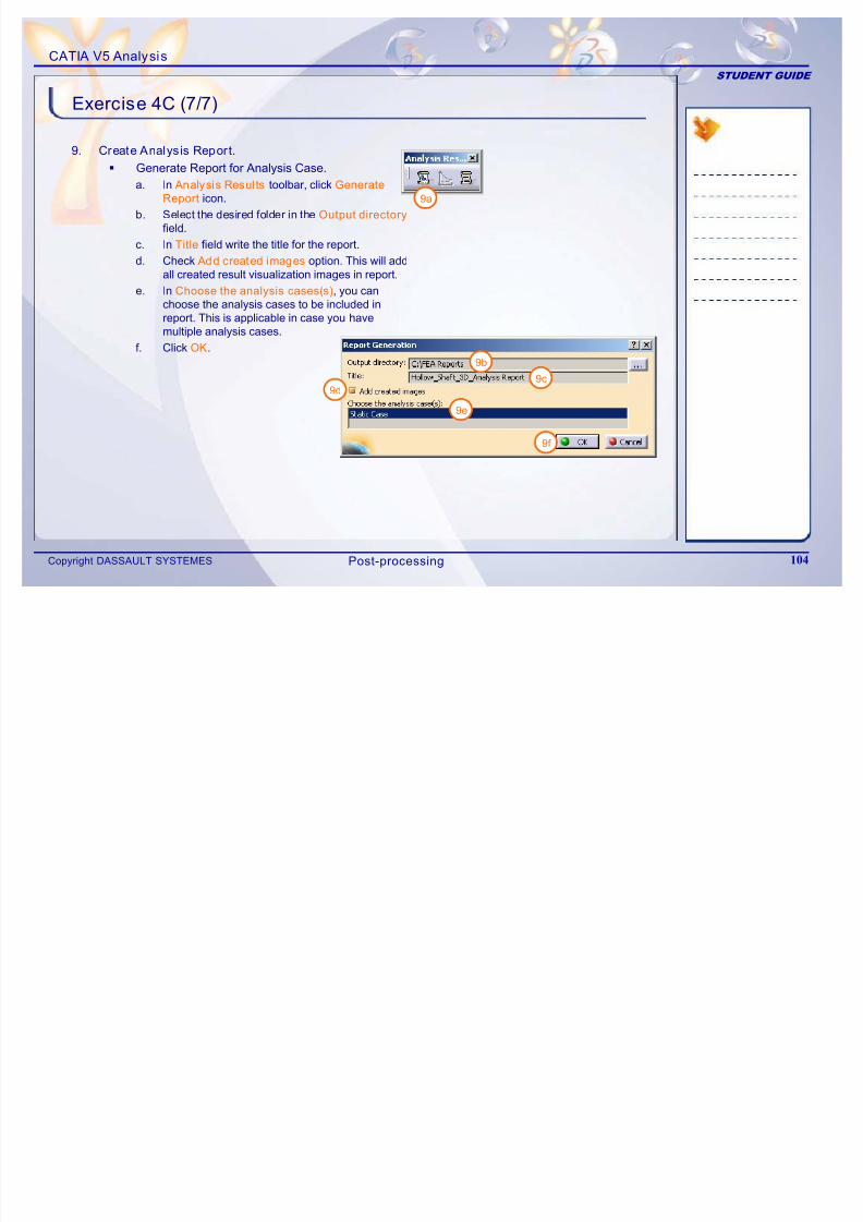
9. Create Analysis Report.
7/16/2019 Edu Cat en v5a Fb v5r19
http://slidepdf.com/reader/full/edu-cat-en-v5a-fb-v5r19 104/172
Copyright DASSAULT SYSTEMES 104
y p
Generate Report for Analysis Case.
a. In Analysis Resul ts toolbar, click Generate
Report icon.
b. Select the desired folder in the Output directory
field.
c. In Title field write the title for the report.
d. Check Add created images option. This will addall created result visualization images in report.
e. In Choose the analysis cases(s), you canchoose the analysis cases to be included inreport. This is applicable in case you havemultiple analysis cases.
f. Click OK.
9a
9b
9c9d
9e
9f
Post-processing
CATIA V5 Analysis
STUDENT GUIDE
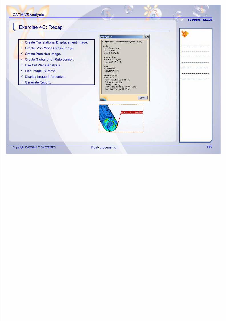
Exercise 4C: Recap
9 C t T l ti l Di l t i
7/16/2019 Edu Cat en v5a Fb v5r19
http://slidepdf.com/reader/full/edu-cat-en-v5a-fb-v5r19 105/172
Copyright DASSAULT SYSTEMES 105
9 Create Translational Displacement image.
9 Create Von Mises Stress Image.
9 Create Precision Image.
9 Create Global error Rate sensor.
9 Use Cut Plane Analysis.
9 Find Image Extrema.
9 Display Image Information.
9 Generate Report .
Post-processing
CATIA V5 Analysis
STUDENT GUIDE
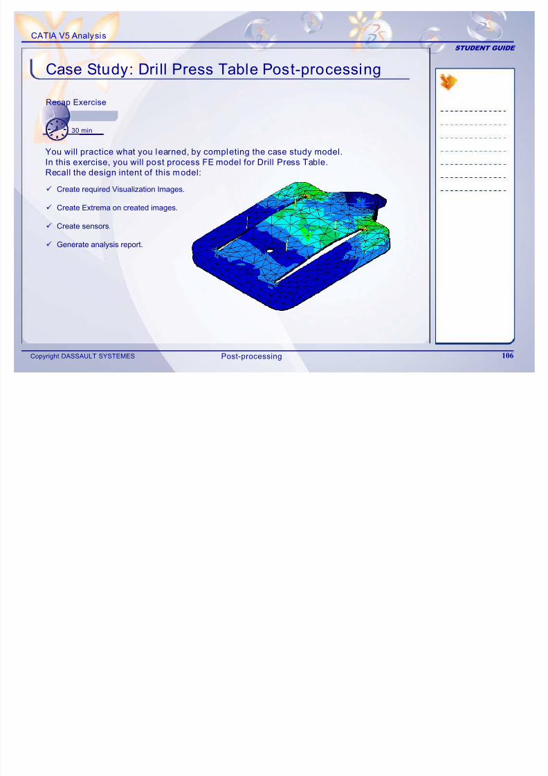
Case Study: Drill Press Table Post-processing
Recap Exercise
7/16/2019 Edu Cat en v5a Fb v5r19
http://slidepdf.com/reader/full/edu-cat-en-v5a-fb-v5r19 106/172
Copyright DASSAULT SYSTEMES 106
Recap Exercise
30 min
You will practice what you learned, by completing the case study model.In this exercise, you will post process FE model for Drill Press Table.
Recall the design intent of this model:
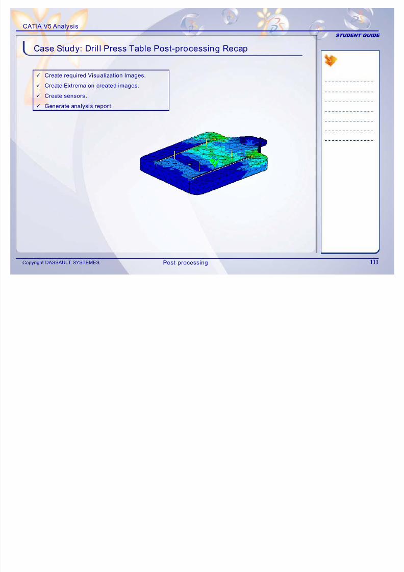
9 Create required Visualization Images.
9 Create Extrema on created images.
9 Create sensors.
9 Generate analysis report.
Post-processing
CATIA V5 Analysis
STUDENT GUIDE
Case Study: Introduction
7/16/2019 Edu Cat en v5a Fb v5r19
http://slidepdf.com/reader/full/edu-cat-en-v5a-fb-v5r19 107/172
Copyright DASSAULT SYSTEMES 107
The case study for this lesson is the Drill Press Table FEmodel post-processing. The focus of this case study is to post-process the computed data as per requirement. You willperform the following steps in order to achieve this.
1. Create required Visualization Images.2. Create Extrema on created images.
3. Create sensors.
4. Generate analysis report.
Drill press Table Translational Displacement Image
Drill press Table FE Model
Post-processing
CATIA V5 Analysis
STUDENT GUIDE
Design Intent (1/2)
9 You will create Translational Displacement Magnitude plot.Y ill fi d th it d f i
7/16/2019 Edu Cat en v5a Fb v5r19
http://slidepdf.com/reader/full/edu-cat-en-v5a-fb-v5r19 108/172
Copyright DASSAULT SYSTEMES 108
You will find the magnitude of maximum averagedisplacement. Also find the location of maximum value of translational displacement. Also observe the Z-directioncomponent image for translational displacement.
Create Translational Displacement Magnitude image
and create Global Extrema for this image.
Create Translational Displacement Component withZ-direction component image and create GlobalExtrema for this image.
9 You will create plots for Maximum Principal stress and
Minimum Principal stress distribution with discontinuous isoand find out the location of maximum values.
Create Principle Stress image with MaximumPrincipal Stress component and create GlobalExtrema for this image.
Create Principal Stress image with MinimumPrincipal Stress component and create GlobalExtrema for this image.
Post-processing
CATIA V5 Analysis
STUDENT GUIDE
Design Intent (2/2)
9 You will create Von Mises stress distribution plot andits location of maximum value in FE model
7/16/2019 Edu Cat en v5a Fb v5r19
http://slidepdf.com/reader/full/edu-cat-en-v5a-fb-v5r19 109/172
Copyright DASSAULT SYSTEMES 109
its location of maximum value in FE model.
Create Von Mises stress image and createGlobal Extrema for this image.
9 You will create Local error distribution and its locationof maximum value.
Create Precision image and create GlobalExtrema for this image.
9 You will create output sensors for Error in Energy,Global Error Rate percentage.
9 You will create Resultant sensor to know reactionsat restraints.
Create Resultant sensor in reaction sensor.
9 You will create Analysis Report with Images.
Post-processing
CATIA V5 Analysis
STUDENT GUIDE
Do It Yourself
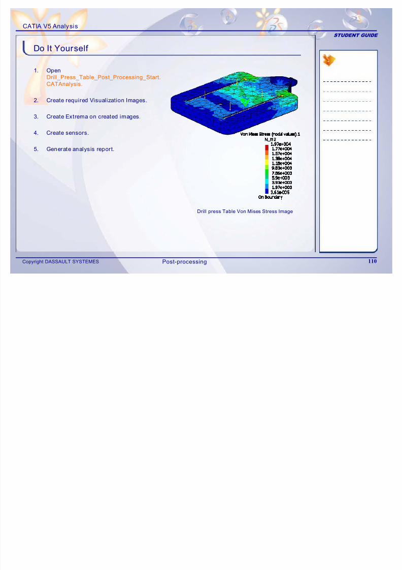
1. Open
Drill Press Table Post Processing Start
7/16/2019 Edu Cat en v5a Fb v5r19
http://slidepdf.com/reader/full/edu-cat-en-v5a-fb-v5r19 110/172
Copyright DASSAULT SYSTEMES 110
Drill_Press_Table_Post_Processing_Start.
CATAnalysis.
2. Create required Visualization Images.
3. Create Extrema on created images.
4. Create sensors.
5. Generate analysis report.
Drill press Table Von Mises Stress Image
Post-processing
CATIA V5 Analysis
STUDENT GUIDE
9 Create required Visualization Images.
Case Study: Dril l Press Table Post-processing Recap
7/16/2019 Edu Cat en v5a Fb v5r19
http://slidepdf.com/reader/full/edu-cat-en-v5a-fb-v5r19 111/172
Copyright DASSAULT SYSTEMES 111
q g
9 Create Extrema on created images.
9 Create sensors .
9 Generate analysis report.
Post-processing

7/16/2019 Edu Cat en v5a Fb v5r19
http://slidepdf.com/reader/full/edu-cat-en-v5a-fb-v5r19 112/172
CATIA V5 Analysis
STUDENT GUIDE
5Mesh Refinement
Learning Objectives:
Upon completion of this lesson you will be able to:
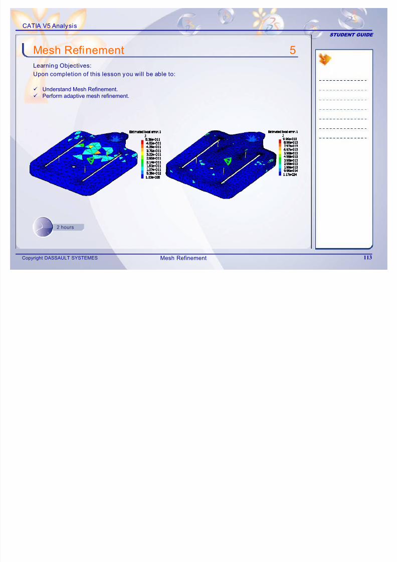
7/16/2019 Edu Cat en v5a Fb v5r19
http://slidepdf.com/reader/full/edu-cat-en-v5a-fb-v5r19 113/172
Copyright DASSAULT SYSTEMES 113
9 Understand Mesh Refinement.9 Perform adaptive mesh refinement.
2 hours
Mesh Refinement
CATIA V5 Analysis
STUDENT GUIDE
The case study for this lesson is the Drill Press TableFE model Post-processing. The case study focuses onmesh refinement in order to obtain requiredvisualization images
Case Study
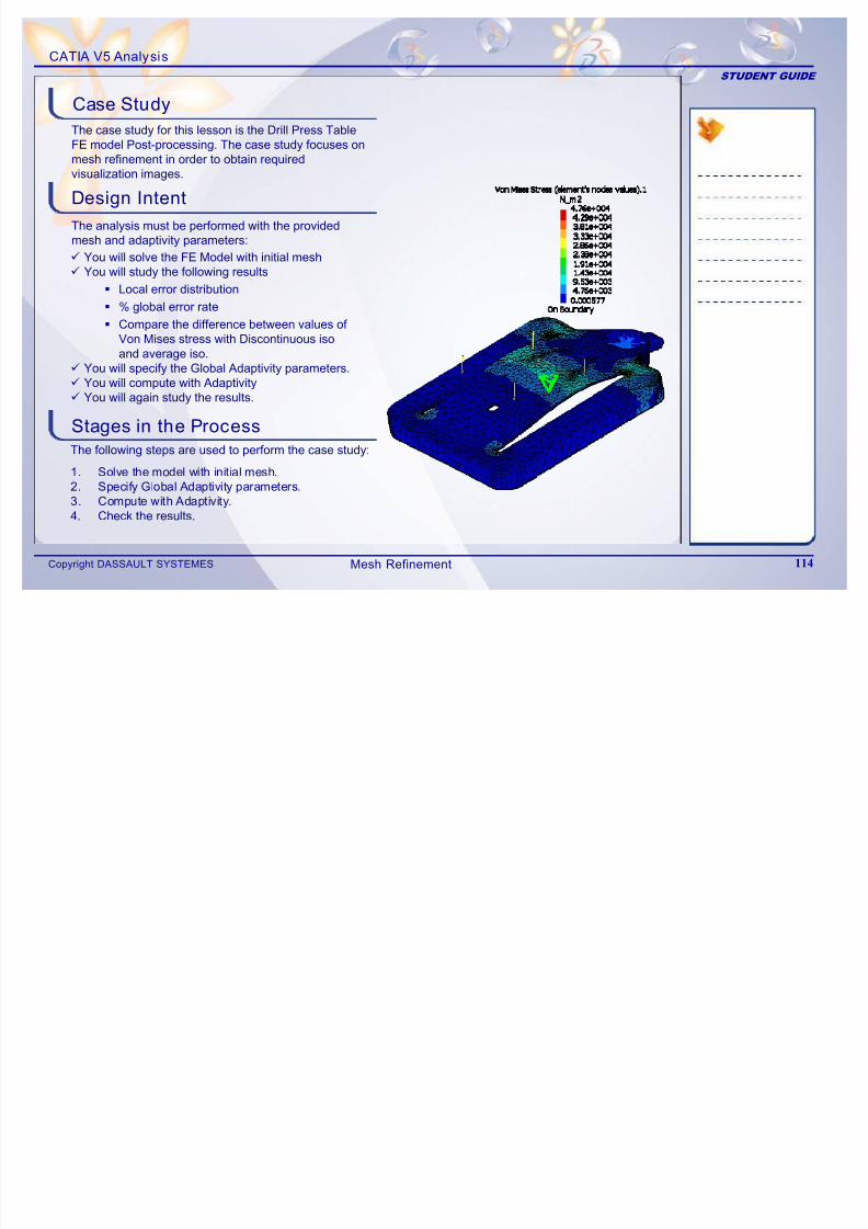
7/16/2019 Edu Cat en v5a Fb v5r19
http://slidepdf.com/reader/full/edu-cat-en-v5a-fb-v5r19 114/172
Copyright DASSAULT SYSTEMES 114
visualization images.
Design Intent
Stages in the Process
9 You will solve the FE Model with initial mesh9 You will study the following results
Local error distribution
% global error rate
Compare the difference between values of Von Mises stress with Discontinuous iso
and average iso.9 You will specify the Global Adaptivity parameters.9 You will compute with Adaptivity9 You will again study the results.
The following steps are used to perform the case study:
1. Solve the model with initial mesh.2. Specify Global Adaptivity parameters.3. Compute with Adaptivity.4. Check the results.
The analysis must be performed with the provided
mesh and adaptivity parameters:
Mesh Refinement
CATIA V5 Analysis
STUDENT GUIDE
What is Mesh Refinement
Initial FE solution provides you the results that aregenerally obtained using simple element types andcoarse meshing. From this solution, you can getth h id f th lt i i l FE
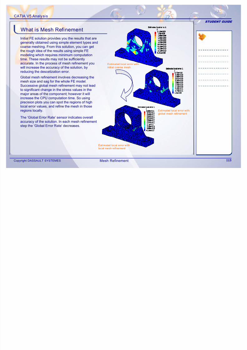
7/16/2019 Edu Cat en v5a Fb v5r19
http://slidepdf.com/reader/full/edu-cat-en-v5a-fb-v5r19 115/172
Copyright DASSAULT SYSTEMES 115
the rough idea of the results using simple FEmodeling which requires minimum computationtime. These results may not be sufficientlyaccurate. In the process of mesh refinement youwill increase the accuracy of the solution, byreducing the descetization error.
Global mesh refinement involves decreasing themesh size and sag for the whole FE model.Successive global mesh refinement may not leadto significant change in the stress values in themajor areas of the component; however itwillincrease the CPU computation time. So usingprecision plots you can spot the regions of highlocal error values, and refine the mesh in thoseregions locally.
The ‘Global Error Rate’ sensor indicates overallaccuracy of the solution. In each mesh refinementstep the ‘Global Error Rate’ decreases.
Estimated local error with
local mesh refinement
Estimated local error with
global mesh refinement
Estimated local error with
initial coarse mesh.
Mesh Refinement
CATIA V5 Analysis
STUDENT GUIDE
In Adaptive Mesh Refinement, the mesh is refinedby increasing or decreasing the element sizes. Theorder of the element remains the same. The meshis refined in the areas where local error estimates
Adaptive Mesh Refinement
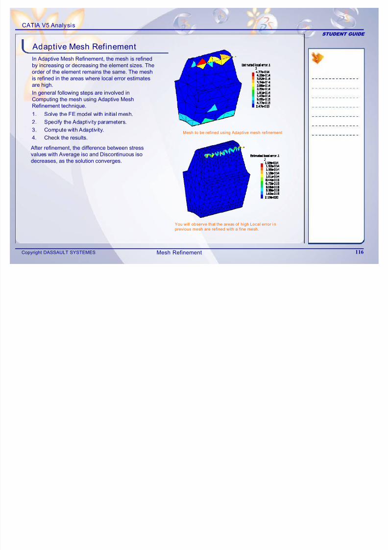
7/16/2019 Edu Cat en v5a Fb v5r19
http://slidepdf.com/reader/full/edu-cat-en-v5a-fb-v5r19 116/172
Copyright DASSAULT SYSTEMES 116
is refined in the areas where local error estimatesare high.
In general following steps are involved inComputing the mesh using Adaptive MeshRefinement technique.
After refinement, the difference between stress
values with Average iso and Discontinuous isodecreases, as the solution converges.
1. Solve the FE model with initial mesh.
2. Specify the Adaptivity parameters.
3. Compute with Adaptivity.
4. Check the results.
You will observe that the areas of high Local error i n
previous mesh are refined with a fine mesh.
Mesh to be refined using Adaptive mesh refinement
Mesh Refinement
CATIA V5 Analysis
STUDENT GUIDE
Adaptive Mesh Refinement
Main Tools
1 New Adaptivit y Entity: Lets you create theadaptivity on a mesh part for a static analysis
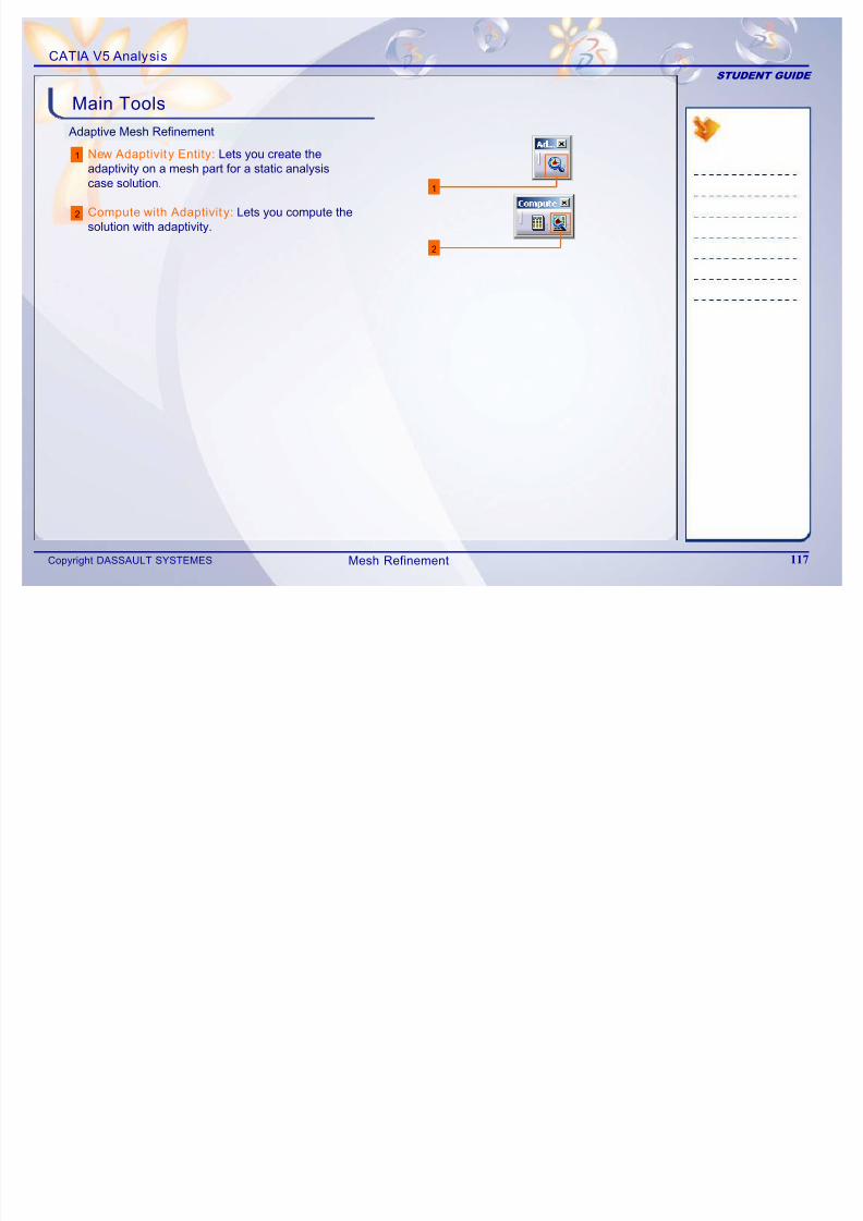
7/16/2019 Edu Cat en v5a Fb v5r19
http://slidepdf.com/reader/full/edu-cat-en-v5a-fb-v5r19 117/172
Copyright DASSAULT SYSTEMES 117
1
2
case solution.
Compute with Adaptivit y: Lets you compute thesolution with adaptivity.
2
Mesh Refinement
CATIA V5 Analysis
STUDENT GUIDE
Case Study: Drill Press Table Mesh Refinement
Recap Exercise
7/16/2019 Edu Cat en v5a Fb v5r19
http://slidepdf.com/reader/full/edu-cat-en-v5a-fb-v5r19 118/172
Copyright DASSAULT SYSTEMES 118
30 min
You will practice what you learned, by completing the case study model. In thisexercise, you wil l how to use adaptive mesh refinement to improve analysis results
for Drill Press Table FE model. Recall the design intent of this model:
9 Solve the model with initial mesh9 Specify Global Adaptivity parameters9 Compute with Adaptivity
9 Check the results
Mesh Refinement
CATIA V5 Analysis
STUDENT GUIDE
Case Study: Introduction
The case study for this lesson is the Drill Press Table FEM d l M h R fi t Th f f thi t d i t
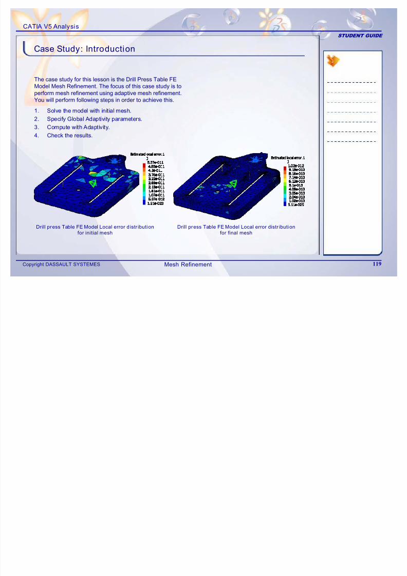
7/16/2019 Edu Cat en v5a Fb v5r19
http://slidepdf.com/reader/full/edu-cat-en-v5a-fb-v5r19 119/172
Copyright DASSAULT SYSTEMES 119
Model Mesh Refinement. The focus of this case study is toperform mesh refinement using adaptive mesh refinement.
You will perform following steps in order to achieve this.
1. Solve the model with initial mesh.
2. Specify Global Adaptivity parameters.
3. Compute with Adaptivity.
4. Check the results.
Drill press Table FE Model Local error distr ibution
for final mesh
Drill press Table FE Model Local error d istr ibution
for initial mesh
Mesh Refinement
CATIA V5 Analysis
STUDENT GUIDE
Design Intent (1/2)
9 You will solve the initial FE model with mesh size 33 mm,Absolute sag 3 mm and parabolic element type.
7/16/2019 Edu Cat en v5a Fb v5r19
http://slidepdf.com/reader/full/edu-cat-en-v5a-fb-v5r19 120/172
Copyright DASSAULT SYSTEMES 120
9 You will study the following results.
View the local error distribution. Note the maximumlocal error value.
View the % global error rate. Note the % global errorrate by creating the global error sensor.
Compare the difference in values of maximum VonMises stress with Discontinuous iso and maximumVon Mises stress with average iso.
9 Specify the Global Adaptivity parameters
Select the mesh part to be refined.
Define the required % global error rate as % objectiveerror. Specify % objective error as 12%.
Mesh Refinement
CATIA V5 Analysis
STUDENT GUIDE
Design Intent (2/2)
9 Compute with Adaptivity.
Specify the iterations to be performed. Specify numberi i 30
7/16/2019 Edu Cat en v5a Fb v5r19
http://slidepdf.com/reader/full/edu-cat-en-v5a-fb-v5r19 121/172
Copyright DASSAULT SYSTEMES 121
iterations as 30.
Keep Global mesh size unmodified. Uncheck allow meshUnrefinement.
Allow Global sags to modify. Check Deacitvate global sags.
9 You will again study the following results.
View the local error distribution. Note the maximumlocal error value.
View the % global error rate. Note the % global error
rate by creating the global error sensor.
Compare the difference in values of maximum VonMises stress with Discontinuous iso and maximumVon Mises stress with average iso.
The above two values should be approximatelysame in order to achieve convergence.
In case the Objective error is not reached, increase the number of iterations and again compute with Adaptivity
More the number of iterations more memory is required for computation. Please make sure that you have enough
disk space compute the solution.
Mesh Refinement
CATIA V5 Analysis
STUDENT GUIDE
Do It Yourself
The following steps offer hints to guide you throughthe mesh refinement of FE model for Drill Press
Table.
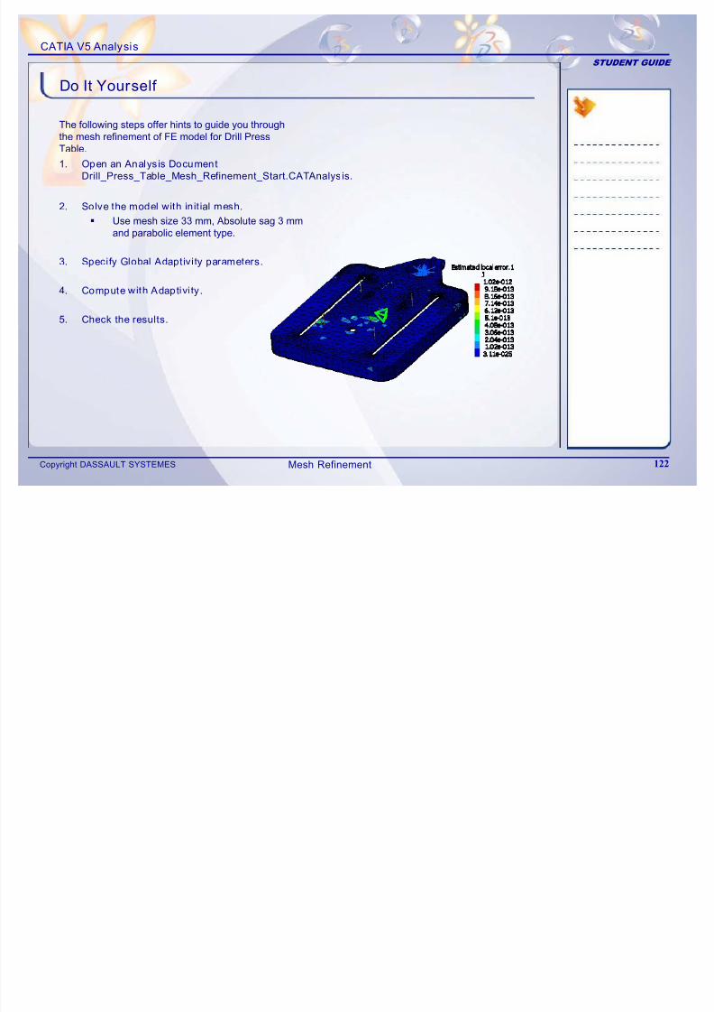
7/16/2019 Edu Cat en v5a Fb v5r19
http://slidepdf.com/reader/full/edu-cat-en-v5a-fb-v5r19 122/172
Copyright DASSAULT SYSTEMES122
abe
1. Open an Analysis Document
Drill_Press_Table_Mesh_Refinement_Start.CATAnalysis.
2. Solve the model with init ial mesh.
Use mesh size 33 mm, Absolute sag 3 mmand parabolic element type.
3. Specify Global Adaptivity parameters.
4. Compute with Adaptivi ty.
5. Check the results.
Mesh Refinement
CATIA V5 Analysis
STUDENT GUIDE
Case Study: Drill Press Table Mesh Refinement Recap
9 Solve the model with initial mesh.
9 Specify Global Adaptivity parameters
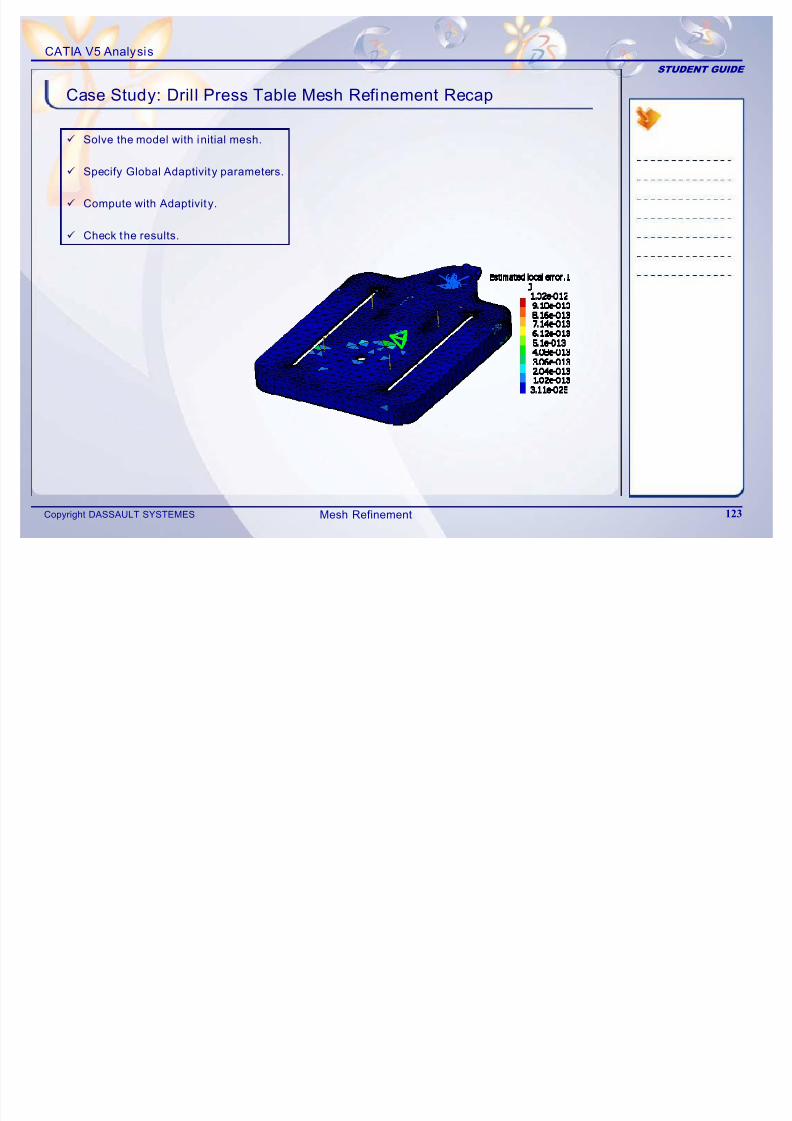
7/16/2019 Edu Cat en v5a Fb v5r19
http://slidepdf.com/reader/full/edu-cat-en-v5a-fb-v5r19 123/172
Copyright DASSAULT SYSTEMES123
9 Specify Global Adaptivity parameters.
9 Compute with Adaptivit y.
9 Check the results.
Mesh Refinement

7/16/2019 Edu Cat en v5a Fb v5r19
http://slidepdf.com/reader/full/edu-cat-en-v5a-fb-v5r19 124/172
CATIA V5 Analysis
STUDENT GUIDE
6 Assembly Structural Analysis
Learning Objectives:
Upon completion of this lesson you will be able to:
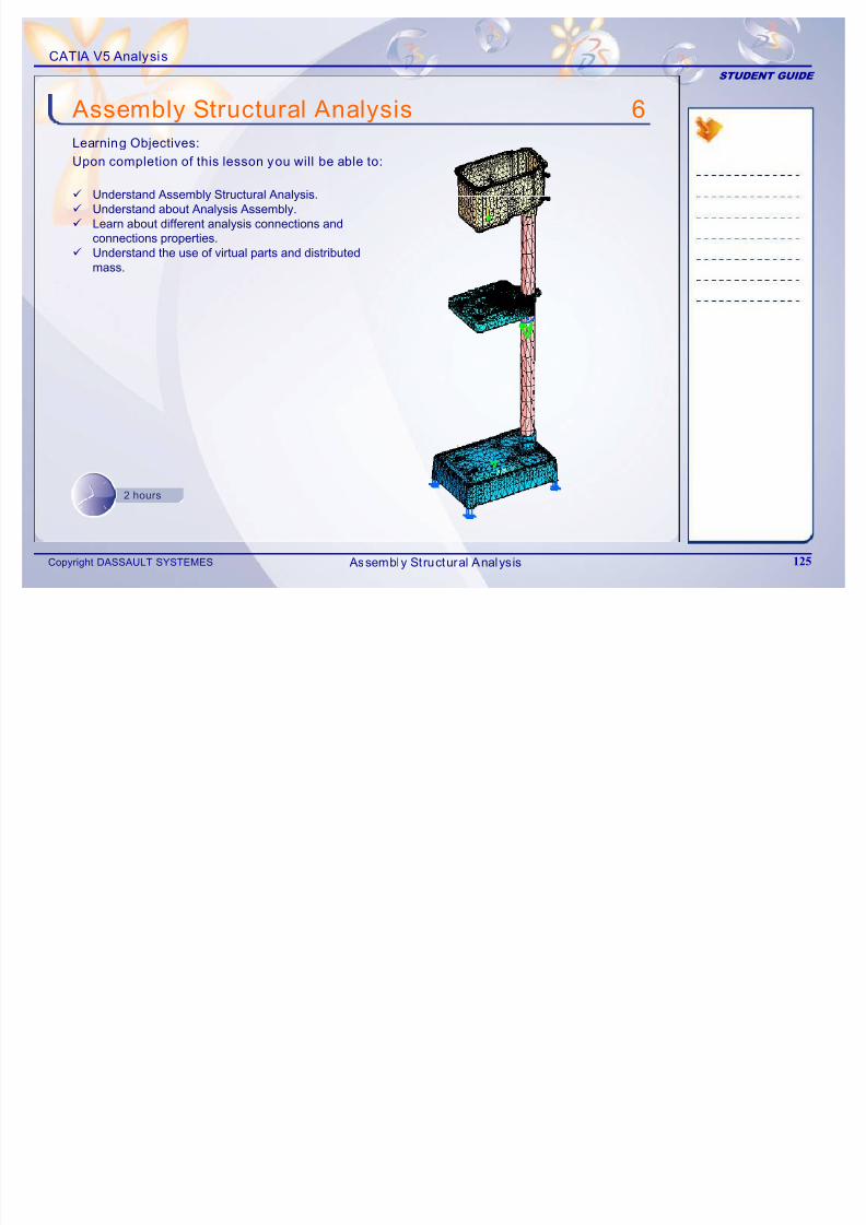
7/16/2019 Edu Cat en v5a Fb v5r19
http://slidepdf.com/reader/full/edu-cat-en-v5a-fb-v5r19 125/172
Copyright DASSAULT SYSTEMES125
9 Understand Assembly Structural Analysis.9 Understand about Analysis Assembly.9 Learn about different analysis connections and
connections properties.9 Understand the use of virtual parts and distributed
mass.
2 hours
Assembly Structural Analysis
CATIA V5 Analysis
STUDENT GUIDE
The case study for this lesson is the Analysis Assembly
of Drill Press Sub-Assembly. The focus of this casestudy is to create FE model of the Drill PressSub-Assembly using Analysis Assembly approach.
Case Study
Housing
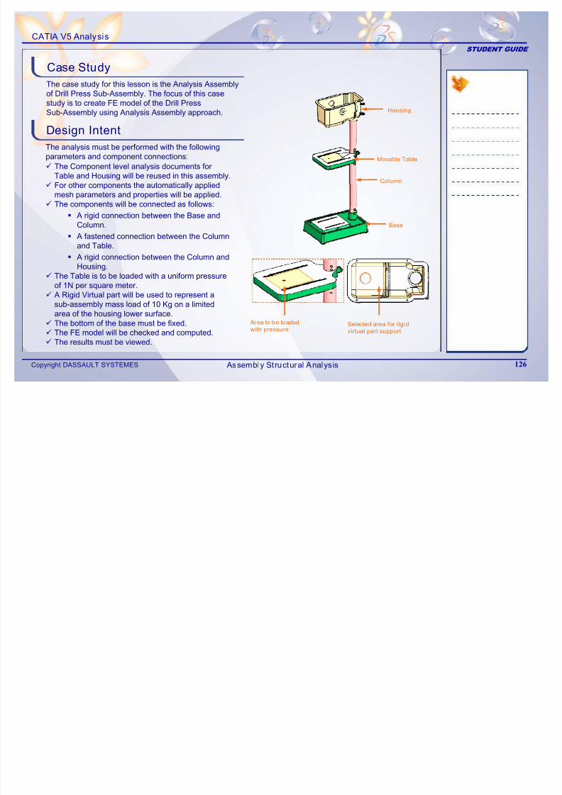
7/16/2019 Edu Cat en v5a Fb v5r19
http://slidepdf.com/reader/full/edu-cat-en-v5a-fb-v5r19 126/172
Copyright DASSAULT SYSTEMES126
Design Intent
The analysis must be performed with the following
parameters and component connections:9 The Component level analysis documents for Table and Housing will be reused in this assembly.
9 For other components the automatically appliedmesh parameters and properties will be applied.
9 The components will be connected as follows:
A rigid connection between the Base and
Column. A fastened connection between the Column
and Table.
A rigid connection between the Column andHousing.
9 The Table is to be loaded with a uniform pressureof 1N per square meter.
9A Rigid Virtual part will be used to represent asub-assembly mass load of 10 Kg on a limitedarea of the housing lower surface.
9 The bottom of the base must be fixed.9 The FE model will be checked and computed.9 The results must be viewed.
Area to be loaded
with pressureSelected area for rigid
virtual part support
Base
Column
Movable Table
Assembly Structural Analysis
CATIA V5 Analysis
STUDENT GUIDE
The following steps are used to perform the case study:
1. Learn different Assembly Structural Analysisapproaches.
2. Create Assembly connections.3 A l C ti ti
Stages in the Process
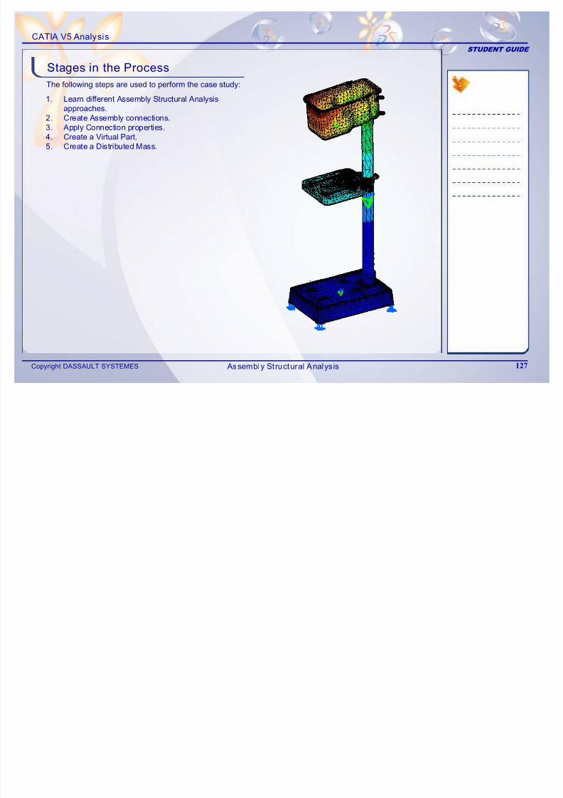
7/16/2019 Edu Cat en v5a Fb v5r19
http://slidepdf.com/reader/full/edu-cat-en-v5a-fb-v5r19 127/172
Copyright DASSAULT SYSTEMES127
3. Apply Connection properties.4. Create a Virtual Part.5. Create a Distributed Mass.
Assembly Structural Analysis
CATIA V5 Analysis
STUDENT GUIDE
Assembly Structural AnalysisProduct
Part 1
Part 2
Assembly Structural Analysis is generally used to
perform the structural analysis of assemblies, bymodeling the physical assemblies using FiniteElement Assemblies.
To simulate the real connection behavioryoucan
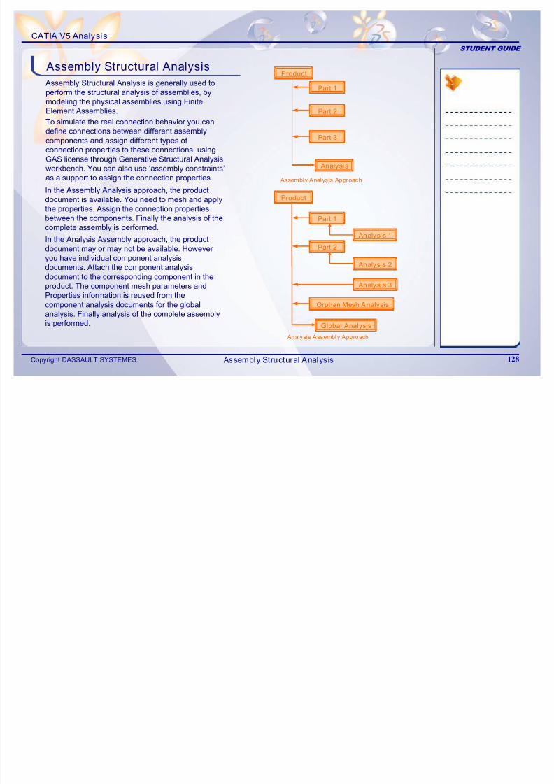
7/16/2019 Edu Cat en v5a Fb v5r19
http://slidepdf.com/reader/full/edu-cat-en-v5a-fb-v5r19 128/172
Copyright DASSAULT SYSTEMES128
In the Assembly Analysis approach, the productdocument is available. You need to mesh and applythe properties. Assign the connection propertiesbetween the components. Finally the analysis of the
complete assembly is performed.
In the Analysis Assembly approach, the productdocument may or may not be available. Howeveryou have individual component analysisdocuments. Attach the component analysisdocument to the corresponding component in theproduct. The component mesh parameters and
Properties information is reused from thecomponent analysis documents for the globalanalysis. Finally analysis of the complete assemblyis performed.
Analysis
Part 3
Product
Part 1
Part 2
Global Analysis
Analysis 1
Analysis 2
Orphan Mesh Analysis
Analysis 3
To simulate the real connection behavior you candefine connections between different assemblycomponents and assign different types of connection properties to these connections, using
GAS license through Generative Structural Analysisworkbench. You can also use ‘assembly constraints’as a support to assign the connection properties. Assembly Analysis Approach
Analysis Assembly Approach
Assembly Structural Analysis
CATIA V5 Analysis
STUDENT GUIDE
In this approach, analysis of individual parts in a
product which are already done, are assembled toform an ‘Analysis Assembly’ and then a final ‘GlobalAnalysis’ is performed for the product.
In case a product is not available, you can create a
Analysis Assembly
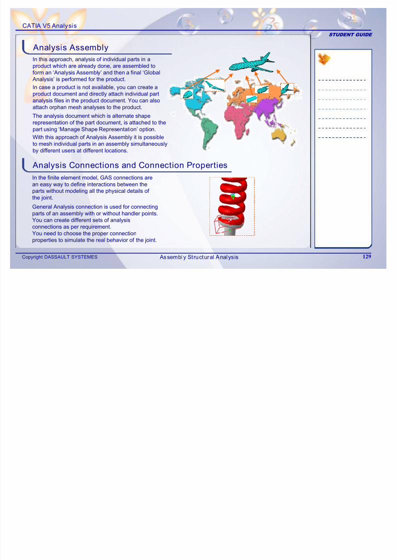
7/16/2019 Edu Cat en v5a Fb v5r19
http://slidepdf.com/reader/full/edu-cat-en-v5a-fb-v5r19 129/172
Copyright DASSAULT SYSTEMES129
Analysis Connections and Connection Properties
case a p oduc s o a a abe, you ca c ea e aproduct document and directly attach individual partanalysis files in the product document. You can alsoattach orphan mesh analyses to the product.
In the finite element model, GAS connections arean easy way to define interactions between theparts without modeling all the physical details of the joint.
The analysis document which is alternate shaperepresentation of the part document, is attached to thepart using ‘Manage Shape Representation’ option.
With this approach of Analysis Assembly it is possibleto mesh individual parts in an assembly simultaneouslyby different users at different locations.
General Analysis connection is used for connectingparts of an assembly with or without handler points.
You can create different sets of analysisconnections as per requirement.
You need to choose the proper connectionproperties to simulate the real behavior of the joint.
Assembly Structural Analysis
CATIA V5 Analysis
STUDENT GUIDE
Virtual parts represent bodies for which no
geometry model is available, but which play animportant role in the analysis of the single part orassembly systems. Virtual parts are connected tocomponents and are used to transmit the
Virtual Parts
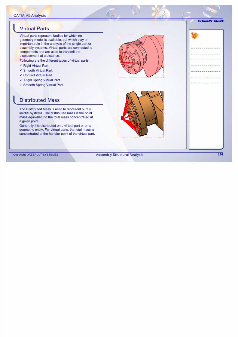
7/16/2019 Edu Cat en v5a Fb v5r19
http://slidepdf.com/reader/full/edu-cat-en-v5a-fb-v5r19 130/172
Copyright DASSAULT SYSTEMES130
displacement at a distance.
Following are the different types of virtual parts:
9 Rigid Virtual Part
9 Smooth Virtual Part.
9 Contact Virtual Part
9 Rigid Spring Virtual Part
9 Smooth Spring Virtual Part
Distributed Mass
The Distributed Mass is used to represent purelyinertial systems. The distributed mass is the pointmass equivalent to the total mass concentrated ata given point.
Generally it is distributed on a virtual part or on ageometric entity. For virtual parts, the total mass isconcentrated at the handler point of the virtual part.
Assembly Structural Analysis
CATIA V5 Analysis
STUDENT GUIDE
Analysis Assembly
1
Main Tools (1/2)
1 Analysis Assembly 2D Viewer: enables you toadd or remove a shape, activate or deactivate anexisting shape, and add or remove a productcomponent in Analysis Assembly
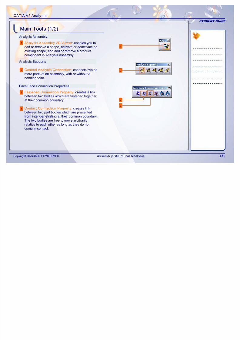
7/16/2019 Edu Cat en v5a Fb v5r19
http://slidepdf.com/reader/full/edu-cat-en-v5a-fb-v5r19 131/172
Copyright DASSAULT SYSTEMES131
2
3
4
Analysis Supports
component in Analysis Assembly.
2
4
3
Face Face Connection Properties
General Analysis Connection: connects two ormore parts of an assembly, with or without ahandler point.
Fastened Connection Property: creates a linkbetween two bodies which are fastened togetherat their common boundary.
Contact Connection Property: creates linkbetween two part bodies which are preventedfrom inter-penetrating at their common boundary.
The two bodies are free to move arbitrarilyrelative to each other as long as they do not
come in contact.
Assembly Structural Analysis
CATIA V5 Analysis
STUDENT GUIDE
Face Face Connection Properties
Main Tools (2/2)
5 5Rigid Connection Property: creates linkbetween two bodies which are stiffened andfastened together at their common boundary, andwill behave as if their interface is infinitely rigid
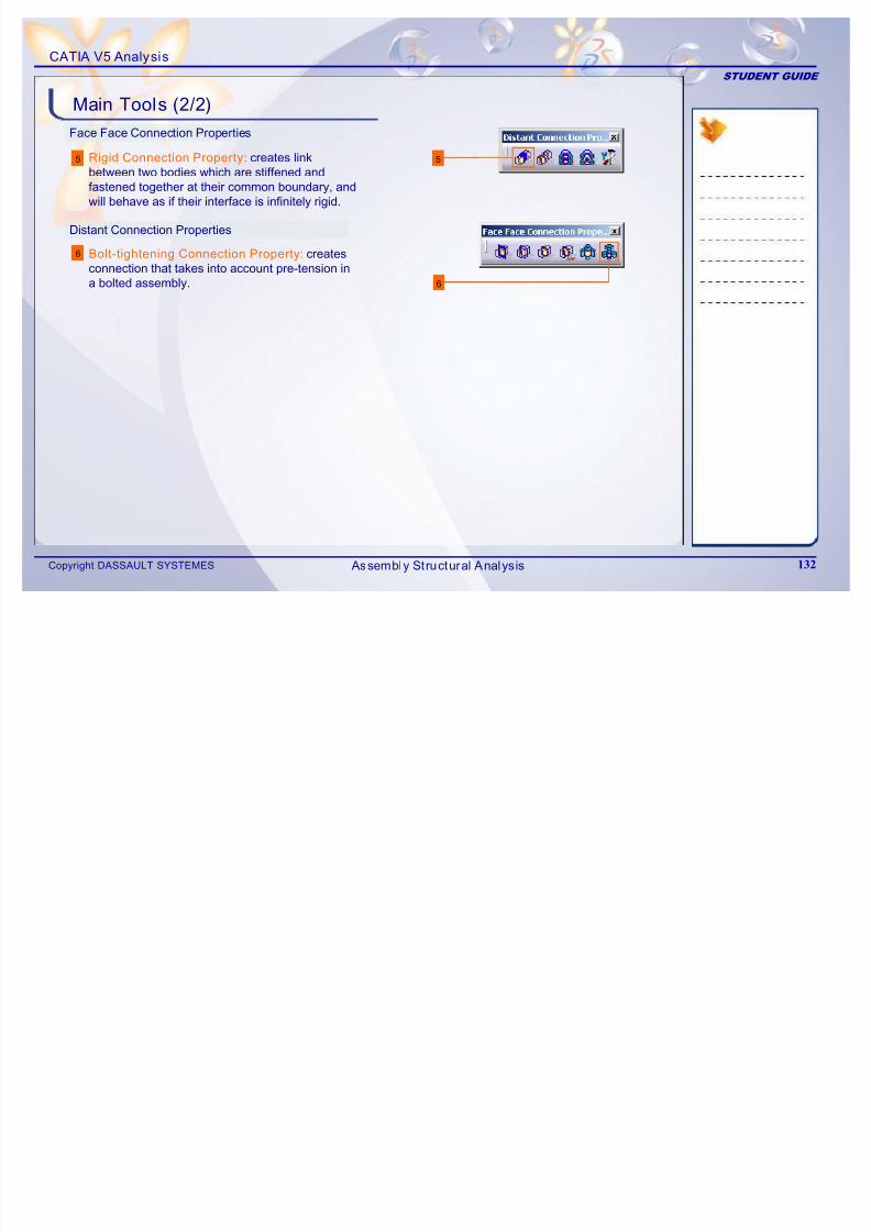
7/16/2019 Edu Cat en v5a Fb v5r19
http://slidepdf.com/reader/full/edu-cat-en-v5a-fb-v5r19 132/172
Copyright DASSAULT SYSTEMES 132
6
6
Distant Connection Properties
will behave as if their interface is infinitely rigid.
Bolt-tightening Connection Property: createsconnection that takes into account pre-tension ina bolted assembly.
Assembly Structural Analysis
CATIA V5 Analysis
STUDENT GUIDE
Exercise 6C
Recap Exercise
15 min
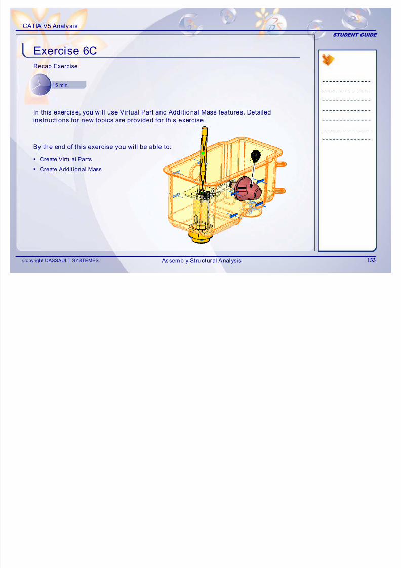
7/16/2019 Edu Cat en v5a Fb v5r19
http://slidepdf.com/reader/full/edu-cat-en-v5a-fb-v5r19 133/172
Copyright DASSAULT SYSTEMES 133
In this exercise, you will use Virtual Part and Addi tional Mass features. Detailedinstructions for new topics are provided for this exercise.
By the end of this exercise you wi ll be able to:
Create Virtual Parts
Create Addit ional Mass
Assembly Structural Analysis
CATIA V5 Analysis
STUDENT GUIDE
Exercise 6C (1/3)
1. Open a Analysis Document.
V5A_Ex_6C_Virtual_Parts_Distributed_Mass_Start.CATAnalysis.
2. Create Virtual Part.
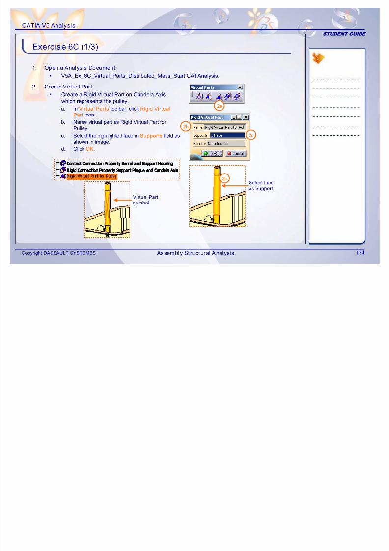
7/16/2019 Edu Cat en v5a Fb v5r19
http://slidepdf.com/reader/full/edu-cat-en-v5a-fb-v5r19 134/172
Copyright DASSAULT SYSTEMES 134
Create a Rigid Virtual Part on Candela Axiswhich represents the pulley.
a. In Virtual Parts toolbar, click Rigid Virtual
Part icon.
b. Name virtual part as Rigid Virtual Part for
Pulley.
c. Select the highlighted face in Supports field asshown in image.
d. Click OK.
2a
2c
2b
Select face
as Suppor t
Virtual Part
symbol
2c
Assembly Structural Analysis
CATIA V5 Analysis
STUDENT GUIDE
Exercise 6C (2/3)
3. Add Pulley mass to virtual part
Create a Distributed mass on the virtual part
a. Click Distributed Mass icon. If the Masses
toolbar is not available, right-click on
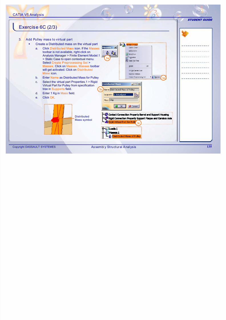
7/16/2019 Edu Cat en v5a Fb v5r19
http://slidepdf.com/reader/full/edu-cat-en-v5a-fb-v5r19 135/172
Copyright DASSAULT SYSTEMES 135
g Analysis Manager > Finite Element Model.1
> Static Case to open contextual menu.Select Create Preprocessing Set >
Masses. Click on Masses. Masses toolbarwill get activated. Click on Distributed
Mass icon.
b. Enter Name as Distributed Mass for Pulley
c. Select the virtual part Properties.1 > Rigid
Virtual Part for Pulley from specificationtree in Supports field.
d. Enter 1 Kg in Mass field.e. Click OK.
3a
3c
3a
3b
Distributed
Mass symbol
Assembly Structural Analysis
CATIA V5 Analysis
STUDENT GUIDE
Exercise 6C (3/3)
4. Convert pulley mass into Load
Apply Gravitation acceleration to Pulley mass
a. In Loads toolbar, click on the Accelerat ion
icon.
4a
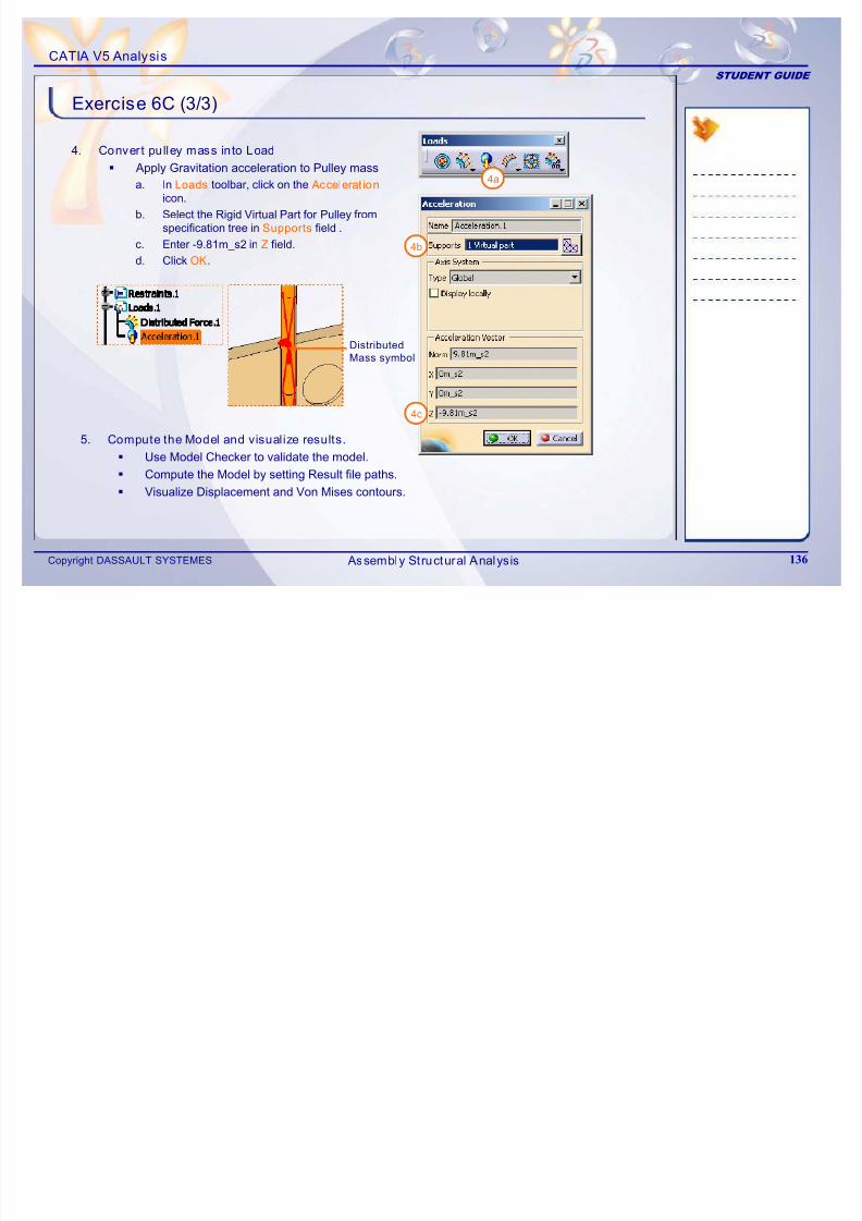
7/16/2019 Edu Cat en v5a Fb v5r19
http://slidepdf.com/reader/full/edu-cat-en-v5a-fb-v5r19 136/172
Copyright DASSAULT SYSTEMES 136
b. Select the Rigid Virtual Part for Pulley fromspecification tree in Supports field .
c. Enter -9.81m_s2 in Z field.d. Click OK.
4b
4c
5. Compute the Model and visualize results.
Use Model Checker to validate the model.
Compute the Model by setting Result file paths.
Visualize Displacement and Von Mises contours.
Distributed
Mass symbol
Assembly Structural Analysis
CATIA V5 Analysis
STUDENT GUIDE
Exercise 6C: Recap
9 Create Virtual Parts.
9 Create Additional Mass.
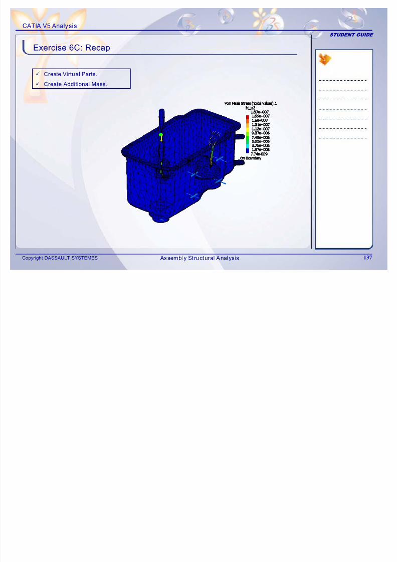
7/16/2019 Edu Cat en v5a Fb v5r19
http://slidepdf.com/reader/full/edu-cat-en-v5a-fb-v5r19 137/172
Copyright DASSAULT SYSTEMES 137 Assembly Structural Analysis
CATIA V5 Analysis
STUDENT GUIDE
Master Project
Analys is of Dri ll Press Assembly
2 hours
7/16/2019 Edu Cat en v5a Fb v5r19
http://slidepdf.com/reader/full/edu-cat-en-v5a-fb-v5r19 138/172
Copyright DASSAULT SYSTEMES 138
The objective of this project is to analyze the complete assembly of the Drill Press
System. You have to study every component of the system, create connections andapply the correct material, forces and boundary conditions to analyze the assembly.
Understand Actual Physical system
Apply Material Propert ies
Create Connections
Apply Forces
Apply Boundary Condi tions
Check the FE Model
Compute the FE Model
Post-processing
By the end of th is Project you wil l be able to:
Master Project
CATIA V5 Analysis
STUDENT GUIDE
Master Project: Overview (1/3)
The following is a list of the steps that arerequired to complete the master pro ject.
Open Dril lPress.CATProduct
1. Understand Actual Physical system.Handle Mechanism
Block Engine
Sub-Assembly
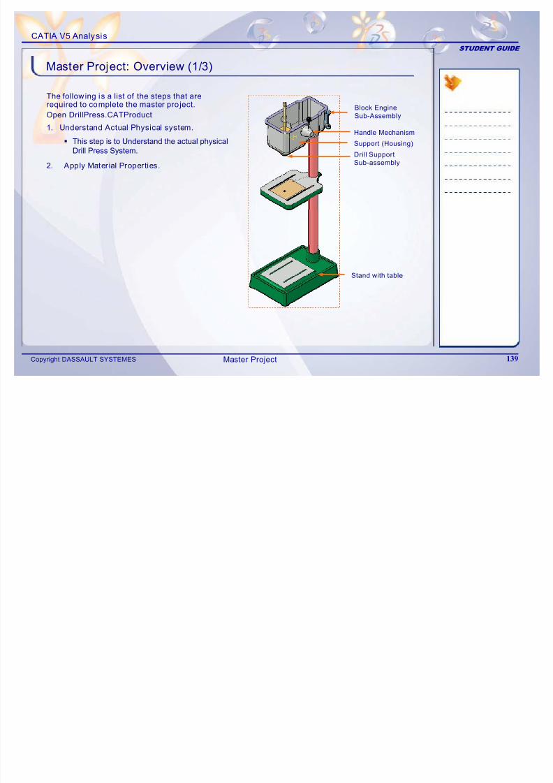
7/16/2019 Edu Cat en v5a Fb v5r19
http://slidepdf.com/reader/full/edu-cat-en-v5a-fb-v5r19 139/172
Copyright DASSAULT SYSTEMES 139
This step is to Understand the actual physicalDrill Press System.
2. Apply Material Properties.
Stand with table
Handle Mechanism
Support (Housing)
Drill Support
Sub-assembly
Master Project
CATIA V5 Analysis
STUDENT GUIDE
Master Project: Overview (2/3)
The following is a list of the steps that arerequired to complete the master pro ject(continued).
3. Create Connections.
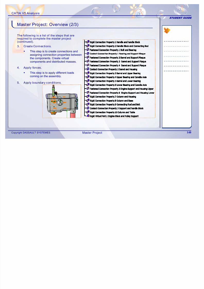
7/16/2019 Edu Cat en v5a Fb v5r19
http://slidepdf.com/reader/full/edu-cat-en-v5a-fb-v5r19 140/172
Copyright DASSAULT SYSTEMES 140
This step is to create connections andassigning connection properties between
the components. Create virtualcomponents and distributed masses.
4. Apply forces.
This step is to apply different loadscoming on the assembly.
5. Apply boundary conditions.
Master Project
CATIA V5 Analysis
STUDENT GUIDE
Master Project: Overview (3/3)
The following is a list of the steps that arerequired to complete the master pro ject(continued).
6. Check the FE model .
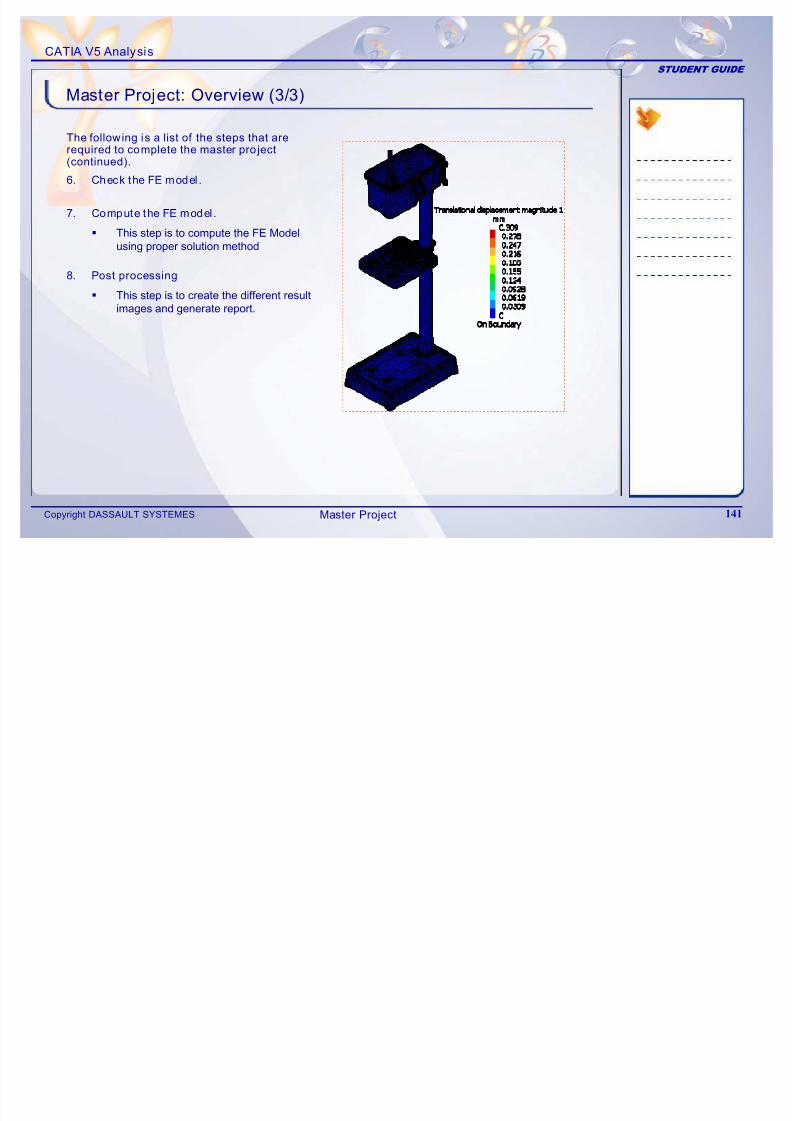
7/16/2019 Edu Cat en v5a Fb v5r19
http://slidepdf.com/reader/full/edu-cat-en-v5a-fb-v5r19 141/172
Copyright DASSAULT SYSTEMES 141
7. Compute the FE model .
This step is to compute the FE Modelusing proper solution method
8. Post processing
This step is to create the different resultimages and generate report.
Master Project
CATIA V5 Analysis
STUDENT GUIDE
Step 1 – Understanding Actual Physical System (1/3)
1. Stand with Table
Handle Mechanism
Block Engine
Sub-Assembly
Support (Housing)
This step is to Understand the actual physical Drill PressSystem. Open the product DrillPress.CATProduct
The assembly consists of the following components
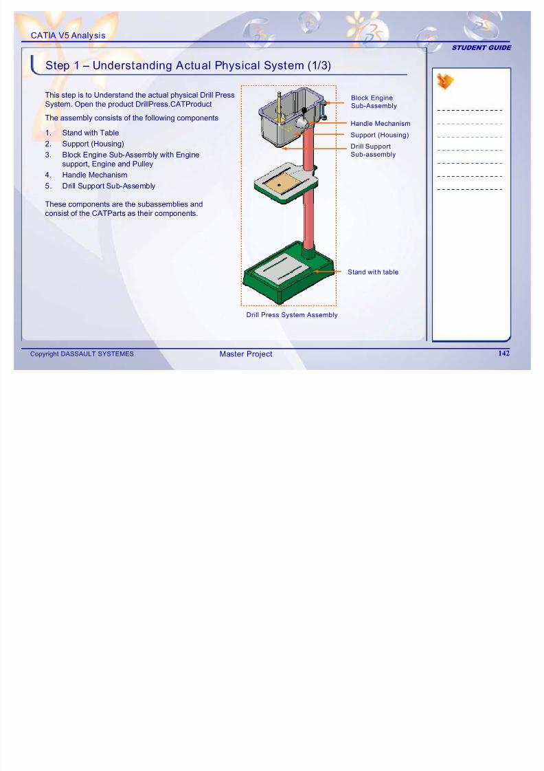
7/16/2019 Edu Cat en v5a Fb v5r19
http://slidepdf.com/reader/full/edu-cat-en-v5a-fb-v5r19 142/172
Copyright DASSAULT SYSTEMES 142
S a d abe
2. Support (Housing)
3. Block Engine Sub-Assembly with Enginesupport, Engine and Pulley
4. Handle Mechanism
5. Drill Support Sub-Assembly
Stand with table
Support (Housing)
Drill Support
Sub-assembly
Drill Press System Assembly
These components are the subassemblies andconsist of the CATParts as their components.
Master Project
CATIA V5 Analysis
STUDENT GUIDE
Step 1 – Understanding Actual Physical System (2/3)
1. Stand with Table
a BaseMovable Table
The components are explained in detail here.
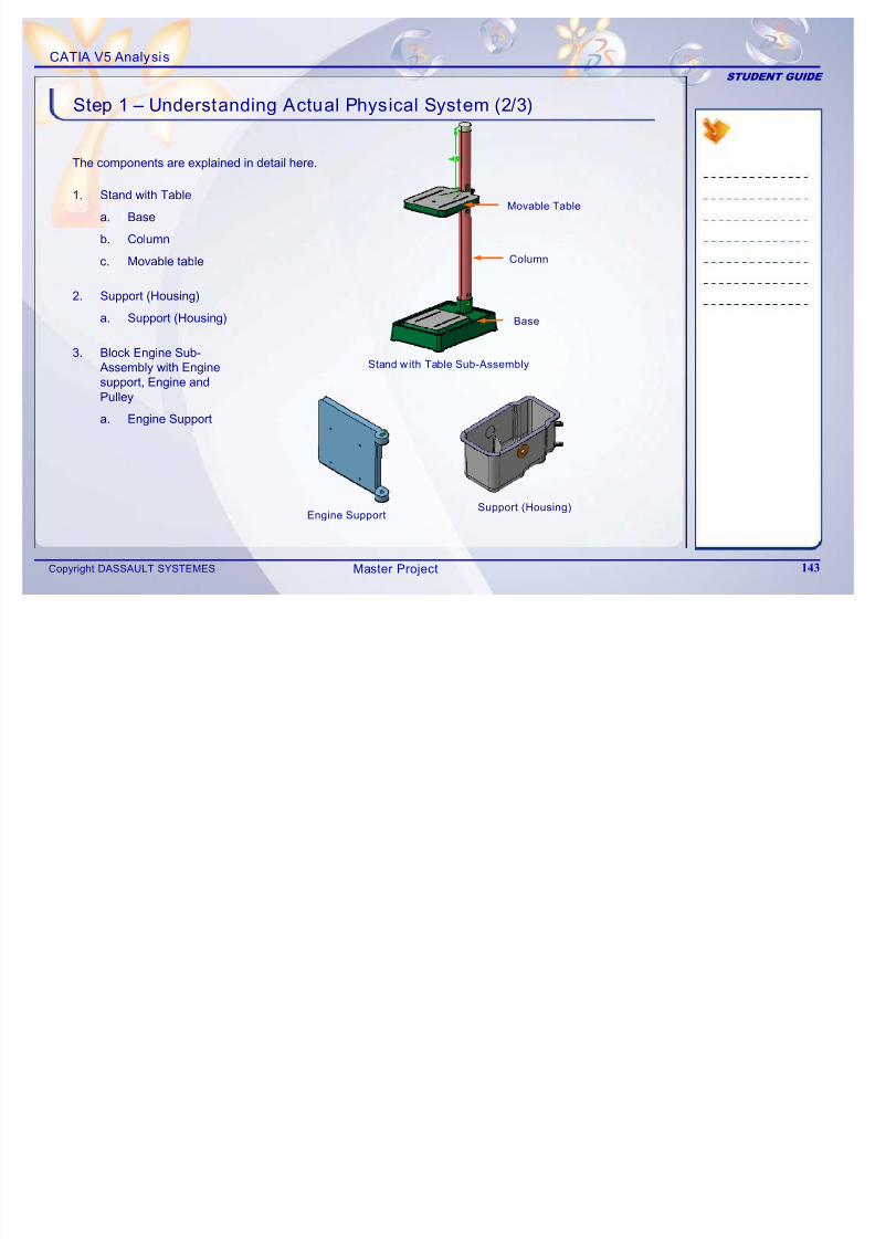
7/16/2019 Edu Cat en v5a Fb v5r19
http://slidepdf.com/reader/full/edu-cat-en-v5a-fb-v5r19 143/172
Copyright DASSAULT SYSTEMES 143
a. Base
b. Column
c. Movable table
2. Support (Housing)
a. Support (Housing)
3. Block Engine Sub-Assembly with Enginesupport, Engine andPulley
a. Engine Support
Base
Column
Stand with Table Sub-Assembly
Support (Housing)Engine Support
Master Project
CATIA V5 Analysis
STUDENT GUIDE
Step 1 – Understanding Actual Physical System (3/3)
4. Handle Mechanism
a. Connecting Rod
b Handle Block
Handle
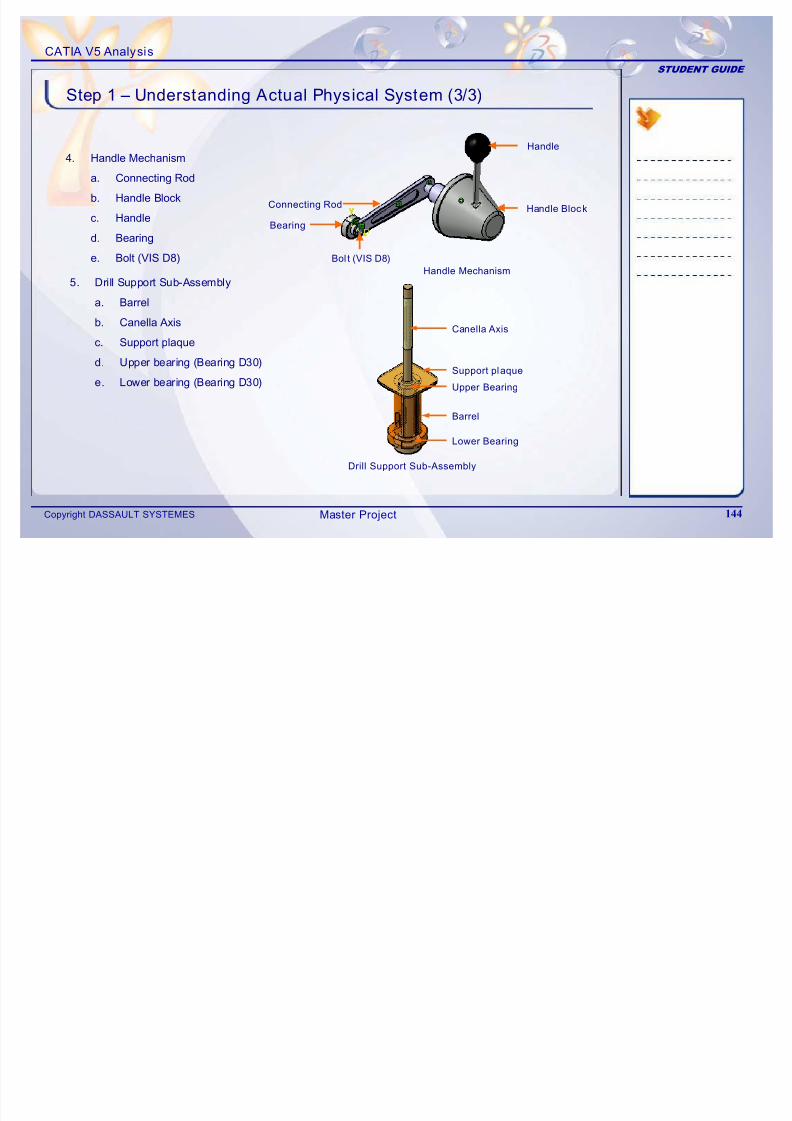
7/16/2019 Edu Cat en v5a Fb v5r19
http://slidepdf.com/reader/full/edu-cat-en-v5a-fb-v5r19 144/172
Copyright DASSAULT SYSTEMES 144
b. Handle Block
c. Handle
d. Bearing
e. Bolt (VIS D8)
5. Drill Support Sub-Assembly
a. Barrel
b. Canella Axisc. Support plaque
d. Upper bearing (Bearing D30)
e. Lower bearing (Bearing D30)
Barrel
Upper Bearing
Canella Axis
Lower Bearing
Support plaque
Drill Support Sub-Assembly
Handle Block
Bearing
Connecting Rod
Bol t (VIS D8)
Handle Mechanism
Master Project
CATIA V5 Analysis
STUDENT GUIDE
Step 2 – Applying Material Properties (1/2)
This step is to apply correct material properties to each component.
Material3D ViewName of theComponent
The material for each component of theassembly is shown in the table. There are twodifferent materials used in the system, one ist l d th i C t I Th i d
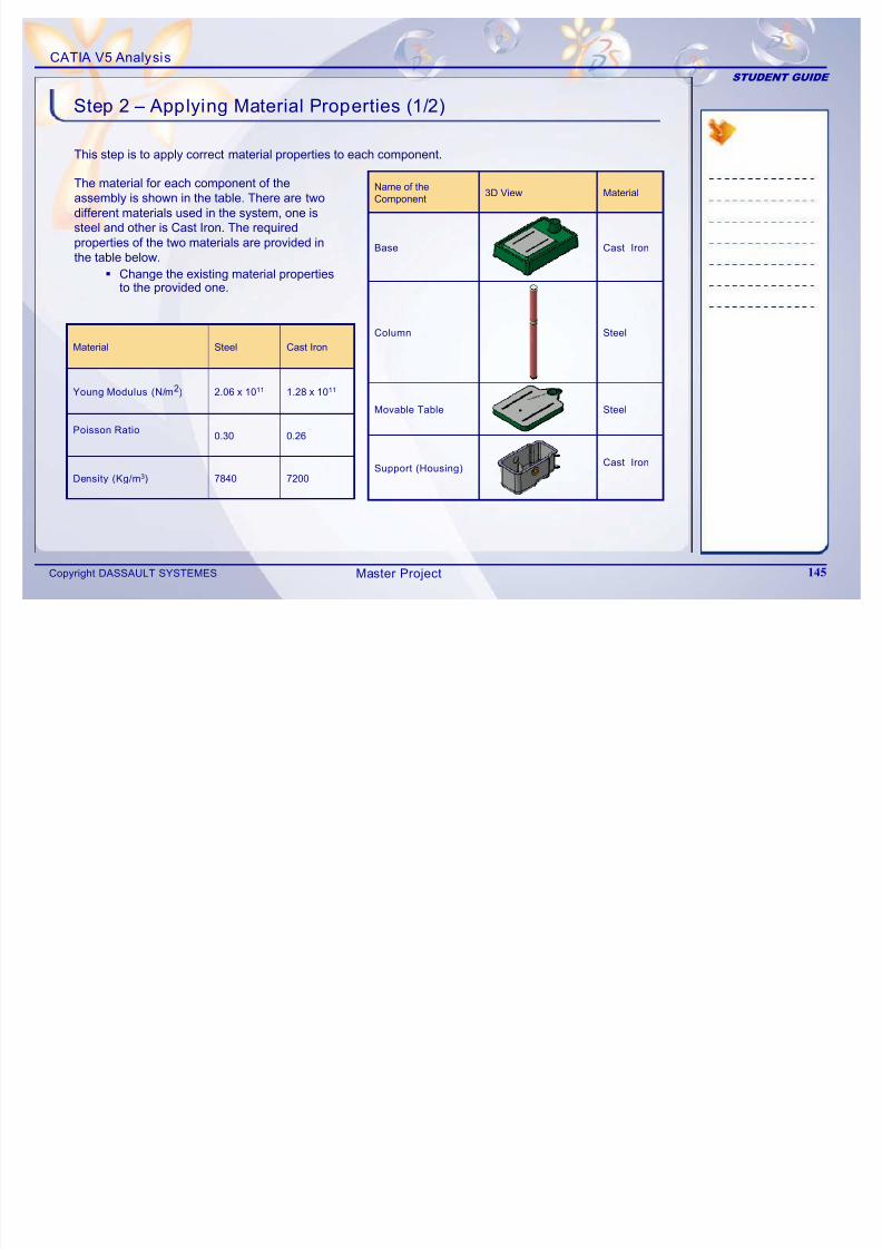
7/16/2019 Edu Cat en v5a Fb v5r19
http://slidepdf.com/reader/full/edu-cat-en-v5a-fb-v5r19 145/172
Copyright DASSAULT SYSTEMES 145
0.260.30Poisson Ratio
1.28 x 10112.06 x 1011Young Modulus (N/m2)
72007840Density (Kg/m3)
Cast IronSteelMaterial
Cast IronSupport (Housing)
SteelMovable Table
SteelColumn
Cast IronBase
steel and other is Cast Iron. The requiredproperties of the two materials are provided in
the table below. Change the existing material properties
to the provided one.
Master Project
CATIA V5 Analysis
STUDENT GUIDE
Step 2 – Applying Material Properties (2/2)
SteelE i S t
Material3D ViewName of theComponent Material3D View
Name of theComponent
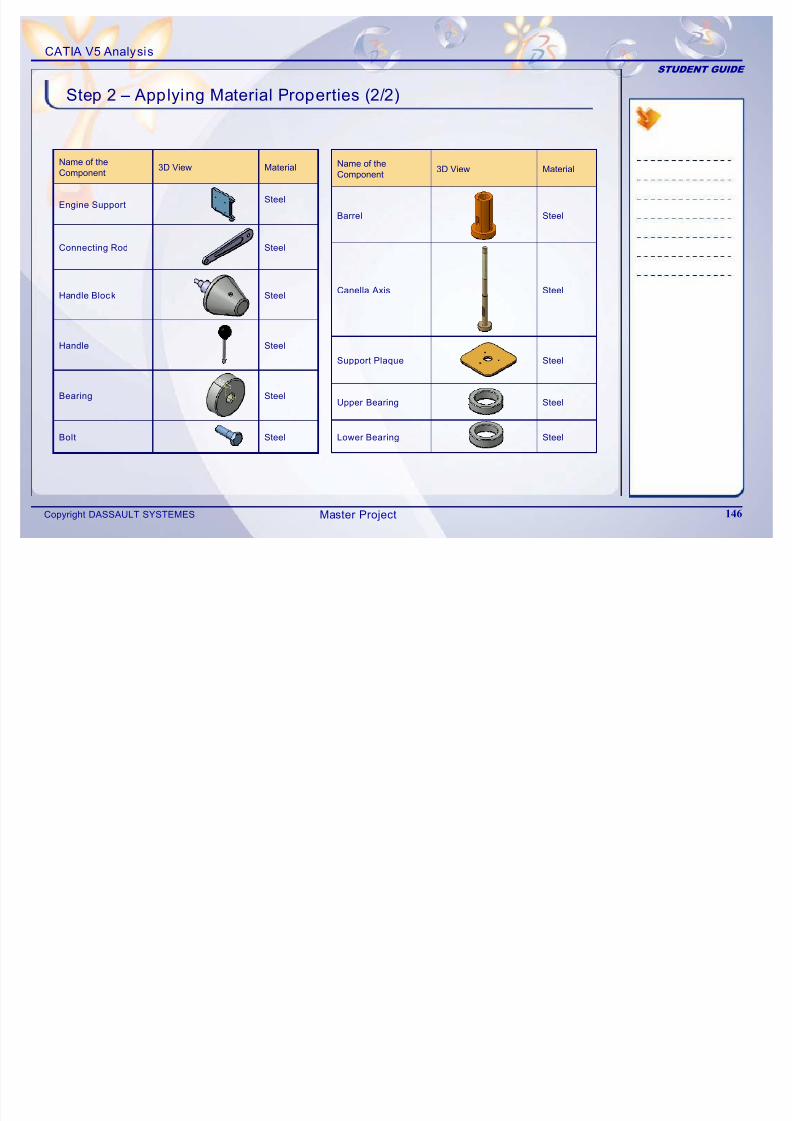
7/16/2019 Edu Cat en v5a Fb v5r19
http://slidepdf.com/reader/full/edu-cat-en-v5a-fb-v5r19 146/172
Copyright DASSAULT SYSTEMES 146
SteelBearing
SteelEngine Support
SteelBolt
SteelHandle
SteelHandle Block
SteelConnecting Rod
SteelUpper Bearing
SteelSupport Plaque
SteelLower Bearing
SteelCanella Axis
SteelBarrel
Master Project
CATIA V5 Analysis
STUDENT GUIDE
Step 3 – Creating Connections (1/8)
1 A l Ri id C ti P t b t
Study the structural connections between the components and assign the connectionproperties accordingly. Create the virtual part and insert masses wherever required.
Create the analysis connections or use the assembly constraints as per requirementsand apply the connection property.
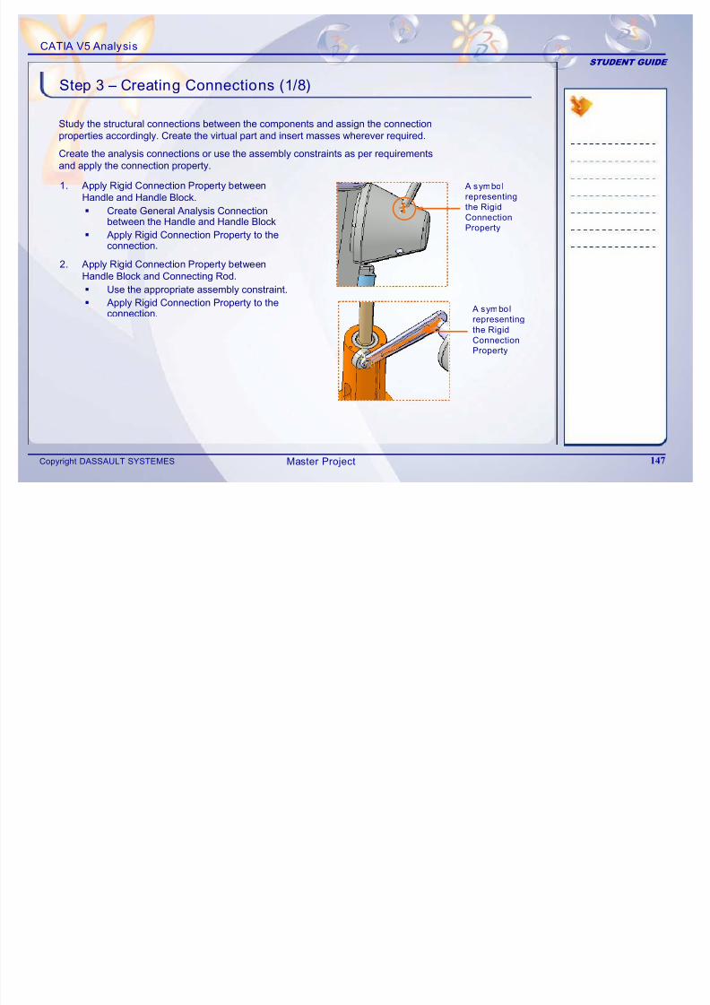
7/16/2019 Edu Cat en v5a Fb v5r19
http://slidepdf.com/reader/full/edu-cat-en-v5a-fb-v5r19 147/172
Copyright DASSAULT SYSTEMES 147
1. Apply Rigid Connection Property betweenHandle and Handle Block.
Create General Analysis Connectionbetween the Handle and Handle Block
Apply Rigid Connection Property to theconnection.
2. Apply Rigid Connection Property betweenHandle Block and Connecting Rod.
Use the appropriate assembly constraint.
Apply Rigid Connection Property to theconnection.
A symbol
representing
the RigidConnection
Property
A symbol
representing
the Rigid
Connection
Property
Master Project
CATIA V5 Analysis
STUDENT GUIDE
Step 3 – Creating Connections (2/8)
3. Apply Fastened Connection Property betweenBolt and Bearing.
Use the appropriate assemblyconstraint.
Apply Fastened Connection Property tothe connection
A symbol
representing the
fastened
Connection
Property
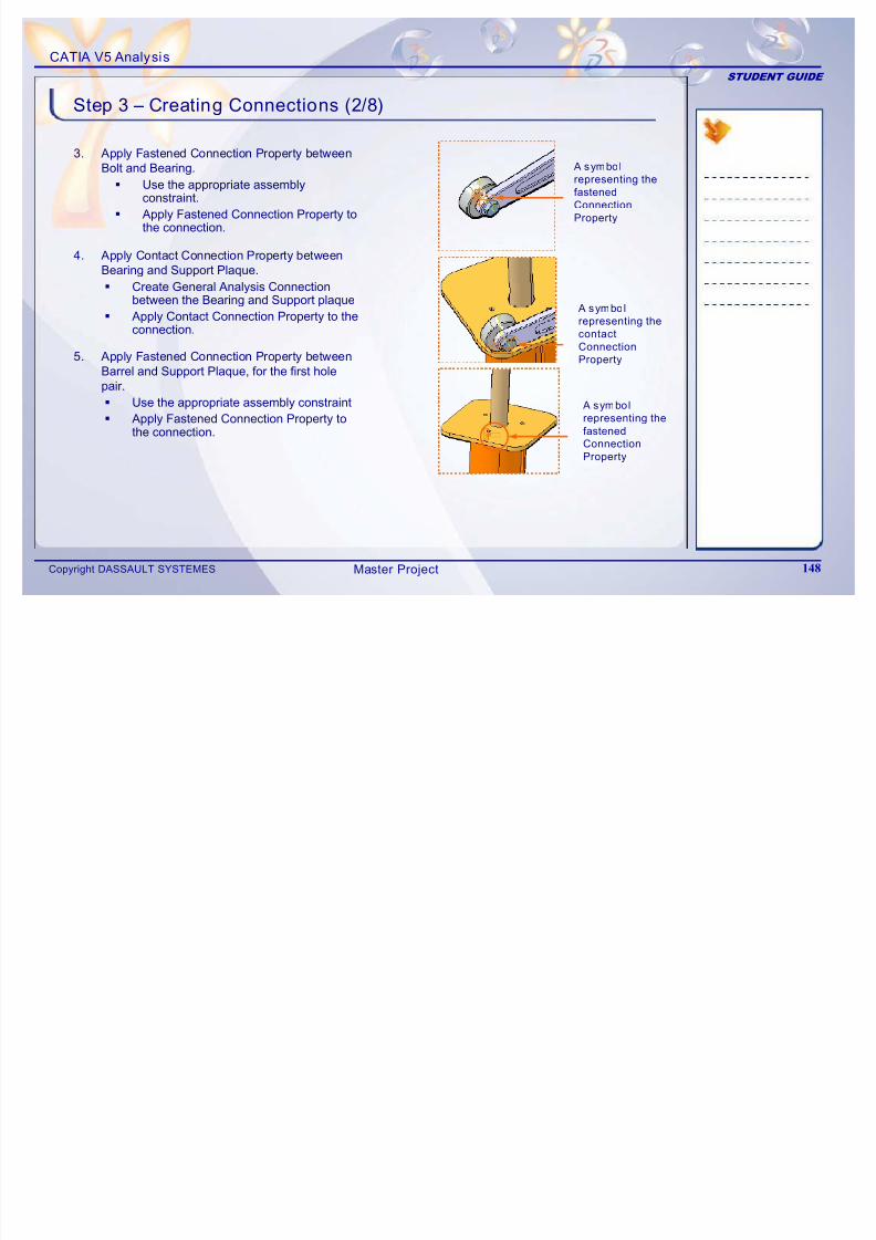
7/16/2019 Edu Cat en v5a Fb v5r19
http://slidepdf.com/reader/full/edu-cat-en-v5a-fb-v5r19 148/172
Copyright DASSAULT SYSTEMES 148
the connection.
4. Apply Contact Connection Property betweenBearing and Support Plaque.
Create General Analysis Connectionbetween the Bearing and Support plaque
Apply Contact Connection Property to theconnection.
5. Apply Fastened Connection Property betweenBarrel and Support Plaque, for the first holepair.
Use the appropriate assembly constraint
Apply Fastened Connection Property tothe connection.
A symbol
representing the
contact
Connection
Property
A symbol
representing the
fastened
Connection
Property
Master Project
CATIA V5 Analysis
STUDENT GUIDE
Step 3 – Creating Connections (3/8)
6. Apply Fastened Connection Property betweenBarrel and Support Plaque, for the second holepair.
Use the appropriate assembly constraint.
Apply Fastened Connection Property tothe connection
A symbol
representing the
fastened
Connection
Property
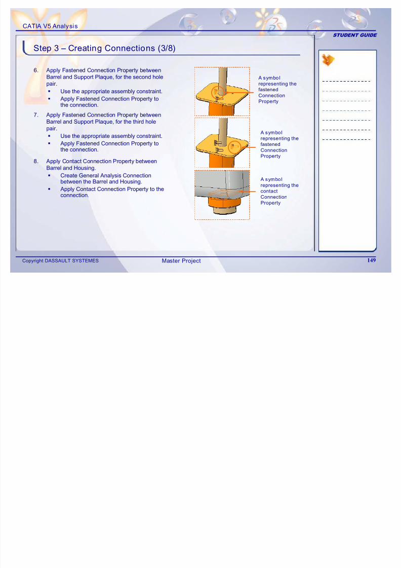
7/16/2019 Edu Cat en v5a Fb v5r19
http://slidepdf.com/reader/full/edu-cat-en-v5a-fb-v5r19 149/172
Copyright DASSAULT SYSTEMES 149
the connection.
7. Apply Fastened Connection Property betweenBarrel and Support Plaque, for the third holepair.
Use the appropriate assembly constraint.
Apply Fastened Connection Property tothe connection.
8. Apply Contact Connection Property between
Barrel and Housing. Create General Analysis Connection
between the Barrel and Housing.
Apply Contact Connection Property to theconnection.
A symbol
representing the
contact
Connection
Property
A symbol
representing the
fastened
Connection
Property
Master Project
CATIA V5 Analysis
STUDENT GUIDE
Step 3 – Creating Connections (4/8)
9. Apply Rigid Connection Property betweenBarrel and Upper Bearing.
Create General Analysis Connectionbetween the Barrel and Upper Bearing.
Apply Rigid Connection Property to theconnection.
A symbol
representing the
rigid Connection
Property
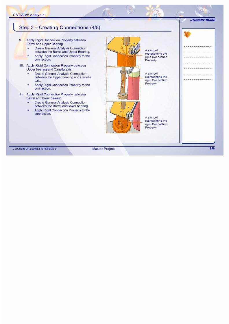
7/16/2019 Edu Cat en v5a Fb v5r19
http://slidepdf.com/reader/full/edu-cat-en-v5a-fb-v5r19 150/172
Copyright DASSAULT SYSTEMES 150
connection.
10. Apply Rigid Connection Property betweenUpper bearing and Canella axis.
Create General Analysis Connectionbetween the Upper bearing and Canellaaxis.
Apply Rigid Connection Property to theconnection.
11. Apply Rigid Connection Property betweenBarrel and lower bearing.
Create General Analysis Connectionbetween the Barrel and lower bearing.
Apply Rigid Connection Property to theconnection.
Property
A symbol
representing the
rigid Connection
Property
A symbol
representing the
rigid ConnectionProperty
Master Project
CATIA V5 Analysis
STUDENT GUIDE
Step 3 – Creating Connections (5/8)
12. Apply Rigid Connection Property betweenLower bearing and Canella axis.
Create General Analysis Connectionbetween the Lower bearing and Canellaaxis.
Apply Rigid Connection Property to the
A symbol
representing the
rigid Connection
Property
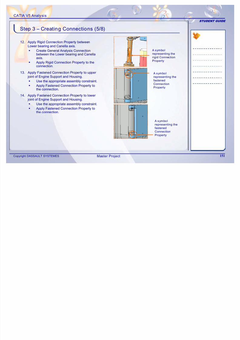
7/16/2019 Edu Cat en v5a Fb v5r19
http://slidepdf.com/reader/full/edu-cat-en-v5a-fb-v5r19 151/172
Copyright DASSAULT SYSTEMES 151
ppy gd Co ec o ope y o econnection.
13. Apply Fastened Connection Property to upper joint of Engine Support and Housing.
Use the appropriate assembly constraint.
Apply Fastened Connection Property tothe connection.
A symbol
representing the
fastened
Connection
Property
14. Apply Fastened Connection Property to lower
joint of Engine Support and Housing. Use the appropriate assembly constraint.
Apply Fastened Connection Property tothe connection.
A symbol
representing the
fastenedConnection
Property
Master Project
CATIA V5 Analysis
STUDENT GUIDE
Step 3 – Creating Connections (6/8)
15. Apply Rigid Connection Property betweenColumn and Support (Housing).
Create General Analysis Connectionbetween the Column and Housing byselecting edges as shown.
Apply Rigid Connection Property to theconnection
A symbol
representing
the rigid
Connection
Edges
to be
selected
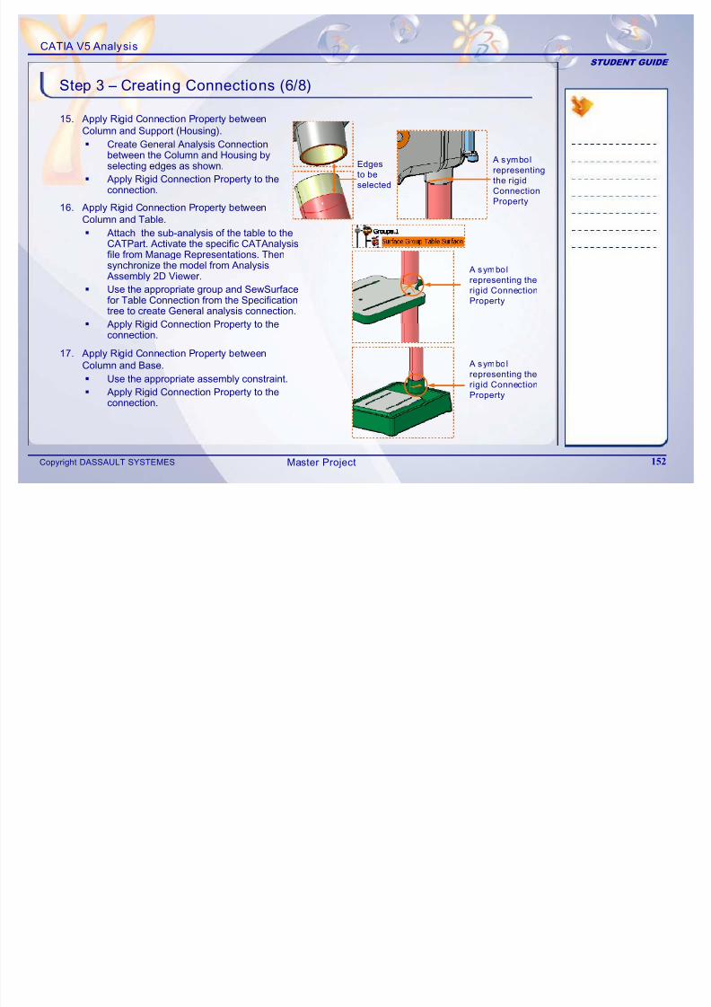
7/16/2019 Edu Cat en v5a Fb v5r19
http://slidepdf.com/reader/full/edu-cat-en-v5a-fb-v5r19 152/172
Copyright DASSAULT SYSTEMES 152
17. Apply Rigid Connection Property betweenColumn and Base.
Use the appropriate assembly constraint.
Apply Rigid Connection Property to theconnection.
A symbol
representing the
rigid ConnectionProperty
connection. Connection
Property
16. Apply Rigid Connection Property betweenColumn and Table.
Attach the sub-analysis of the table to theCATPart. Activate the specific CATAnalysisfile from Manage Representations. Thensynchronize the model from AnalysisAssembly 2D Viewer.
Use the appropriate group and SewSurfacefor Table Connection from the Specificationtree to create General analysis connection.
Apply Rigid Connection Property to theconnection.
A symbol
representing the
rigid Connection
Property
Master Project
CATIA V5 Analysis
STUDENT GUIDE
Step 3 – Creating Connections (7/8)
19 ApplyContactConnection Property between
18. Apply Rigid Connection Property betweenConnecting rod and Bolt.
Use the appropriate assembly constraint.
Apply Rigid Connection Property to theconnection.
A symbol
representing the
rigid Connection
Property
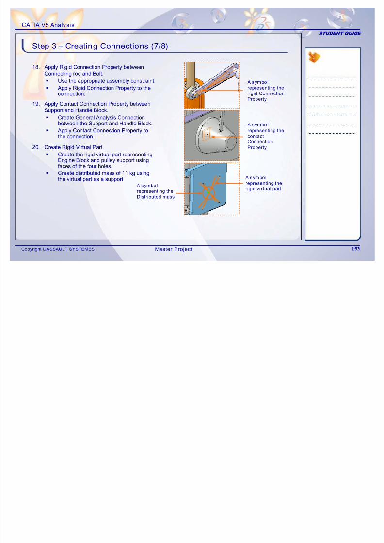
7/16/2019 Edu Cat en v5a Fb v5r19
http://slidepdf.com/reader/full/edu-cat-en-v5a-fb-v5r19 153/172
Copyright DASSAULT SYSTEMES 153
20. Create Rigid Virtual Part.
Create the rigid virtual part representing
Engine Block and pulley support usingfaces of the four holes.
Create distributed mass of 11 kg usingthe virtual part as a support.
19. Apply Contact Connection Property between
Support and Handle Block. Create General Analysis Connection
between the Support and Handle Block.
Apply Contact Connection Property tothe connection.
A symbol
representing the
contact
Connection
Property
A symbol
representing the
rigid vi rtual part A symbol
representing the
Distributed mass
Master Project
CATIA V5 Analysis
STUDENT GUIDE
Step 3 – Creating Connections (8/8)
21. Create distributed mass representing pulley.
Create distributed mass of 2 kg on theouter surface of the canella axis.
A symbol
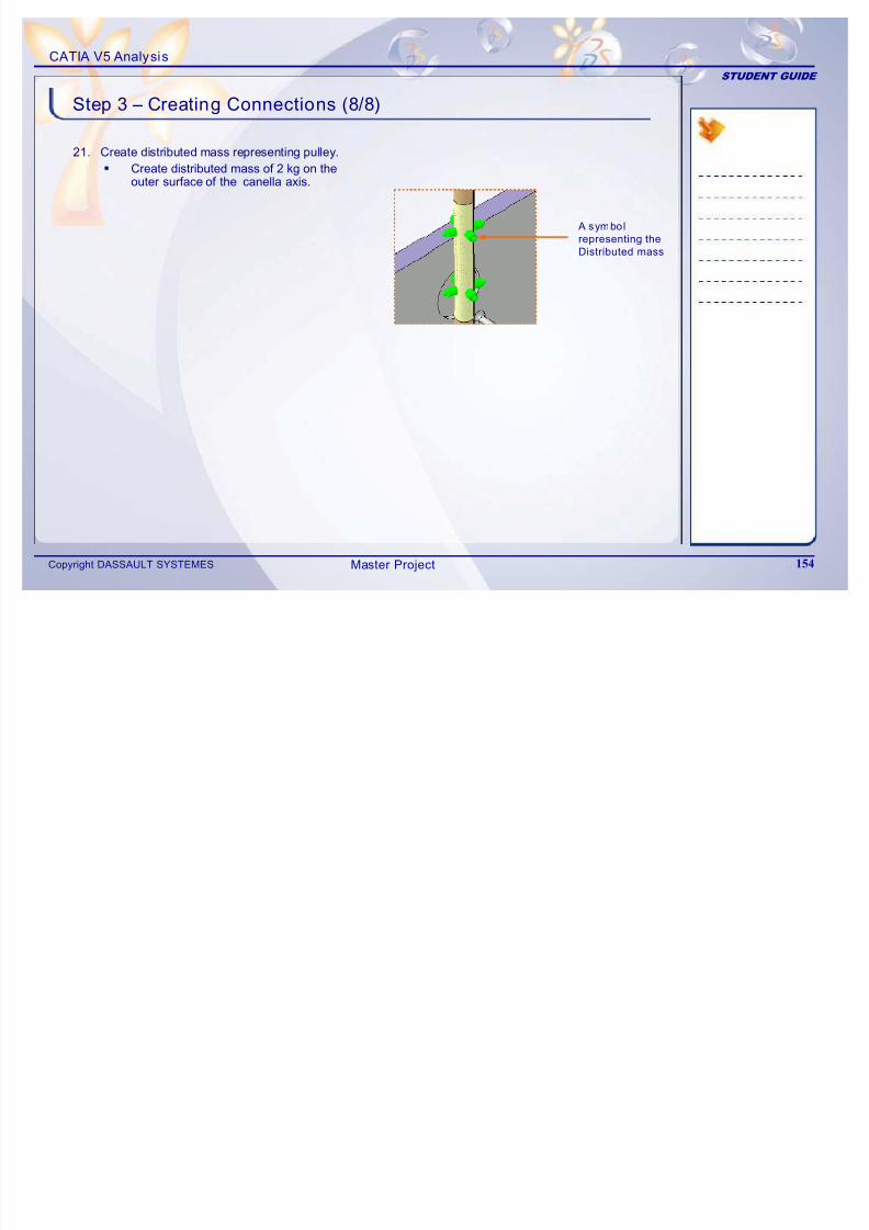
7/16/2019 Edu Cat en v5a Fb v5r19
http://slidepdf.com/reader/full/edu-cat-en-v5a-fb-v5r19 154/172
Copyright DASSAULT SYSTEMES 154
representing the
Distributed mass
Master Project
CATIA V5 Analysis
STUDENT GUIDE
Step 4 – Applying forces (1/2)
1. Force applied on the handle, for drilling operation
This step is to study the different Loads acting on the DrillPress Assembly.
The following are the forces acting on the assemblycomponents.
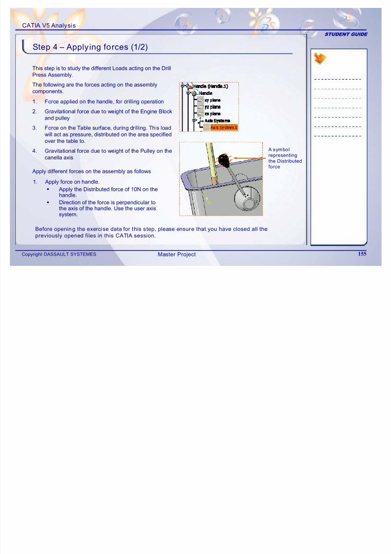
7/16/2019 Edu Cat en v5a Fb v5r19
http://slidepdf.com/reader/full/edu-cat-en-v5a-fb-v5r19 155/172
Copyright DASSAULT SYSTEMES 155
2. Gravitational force due to weight of the Engine Blockand pulley
3. Force on the Table surface, during drilling. This loadwill act as pressure, distributed on the area specifiedover the table to.
4. Gravitational force due to weight of the Pulley on thecanella axis
1. Apply force on handle.
Apply the Distributed force of 10N on thehandle.
Direction of the force is perpendicular to
the axis of the handle. Use the user axissystem.
Apply different forces on the assembly as follows
A symbol
representing
the Distributedforce
Before opening the exercise data for this step, please ensure that you have closed all the
previously opened files in this CATIA session.
Master Project
CATIA V5 Analysis
STUDENT GUIDE
Step 4 – Applying forces (2/2)
3. Apply pressure on the table surface.
Apply pressure of 1N/m2
2. Apply gravitational force due to weight of Engine block and pulley.
Apply acceleration due to gravity (9.81m/s2) on the virtual part.
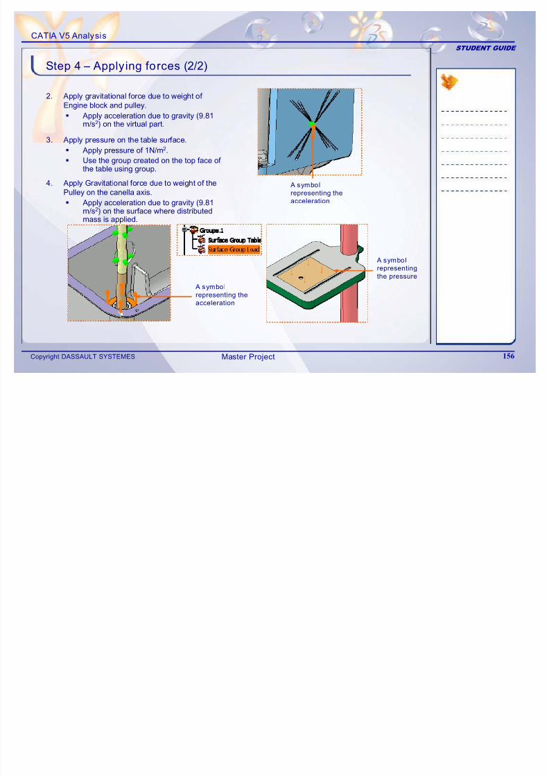
7/16/2019 Edu Cat en v5a Fb v5r19
http://slidepdf.com/reader/full/edu-cat-en-v5a-fb-v5r19 156/172
Copyright DASSAULT SYSTEMES 156
Apply pressure of 1N/m2.
Use the group created on the top face of the table using group.
4. Apply Gravitational force due to weight of thePulley on the canella axis.
Apply acceleration due to gravity (9.81m/s2) on the surface where distributedmass is applied.
A symbol
representing the
acceleration
A symbol
representing theacceleration
A symbol
representing
the pressure
Master Project
CATIA V5 Analysis
STUDENT GUIDE
Step 5 – Applying Boundary Condit ions (1/2)
This step is to apply the boundary conditions. The first stepis to understand the actual boundary conditions.
The bottom surface of the Base and the Barrel arerestrained to move. So they are totally clamped.
The side surfaces of the Support (housing) and the outersurfaces of the barrel and canella axis are free to move in
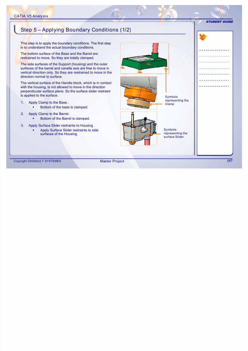
7/16/2019 Edu Cat en v5a Fb v5r19
http://slidepdf.com/reader/full/edu-cat-en-v5a-fb-v5r19 157/172
Copyright DASSAULT SYSTEMES 157
surfaces of the barrel and canella axis are free to move in
vertical direction only. So they are restrained to move in thedirection normal to surface.
The vertical surface of the Handle block, which is in contactwith the housing, is not allowed to move in the directionperpendicular surface plane. So the surface slider restraintis applied to the surface.
1. Apply Clamp to the Base . Bottom of the base is clamped.
2. Apply Clamp to the Barrel.
Bottom of the Barrel is clamped.
3. Apply Surface Slider restraints to Housing .
Apply Surface Slider restraints to side
surfaces of the Housing.
Symbols
representing the
Clamp
Symbols
representing thesurface Slider
Master Project
CATIA V5 Analysis
STUDENT GUIDE
Step 5 – Applying Boundary Condit ions (2/2)
4. Apply Surface Slider restraints to Barrel andCanella Axis.
Apply Slider restraints to outer surfaceof the Barrel and Canella Axis.
Symbols
representing the
surface Slider
5. Apply Surface Slider restraints to Handle block.
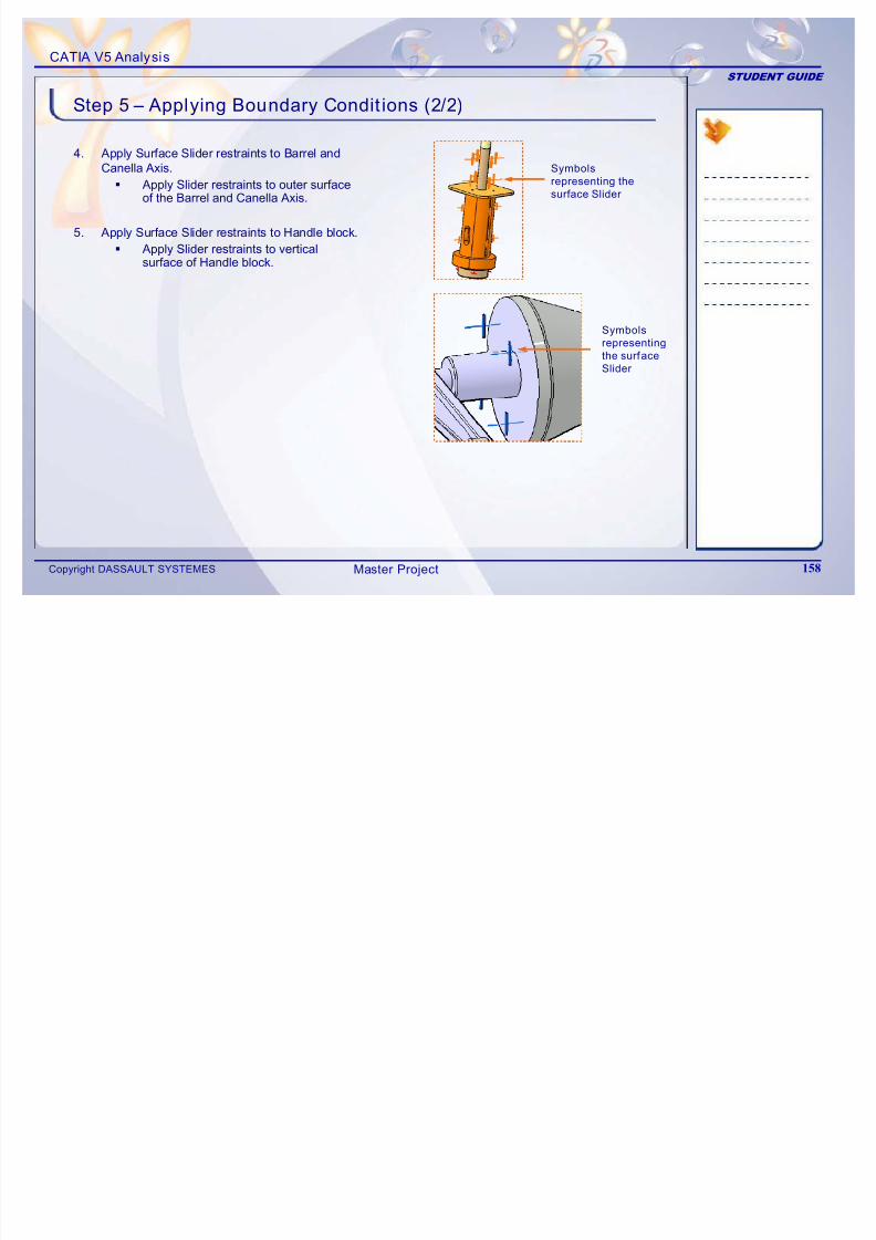
7/16/2019 Edu Cat en v5a Fb v5r19
http://slidepdf.com/reader/full/edu-cat-en-v5a-fb-v5r19 158/172
Copyright DASSAULT SYSTEMES 158
Apply Slider restraints to verticalsurface of Handle block.
Symbols
representing
the surface
Slider
Master Project
CATIA V5 Analysis
STUDENT GUIDE
Step 6 – Checking the FE Model
This step is to Check the created Finite Element model.From the first step to the previous step, the FE preprocessing of the assembly model iscompleted. It is necessary to validate the model, before carrying out the computation step.
Check the Model using Model Checker.
Confirm the message “The whole model isconsistent” with green signal
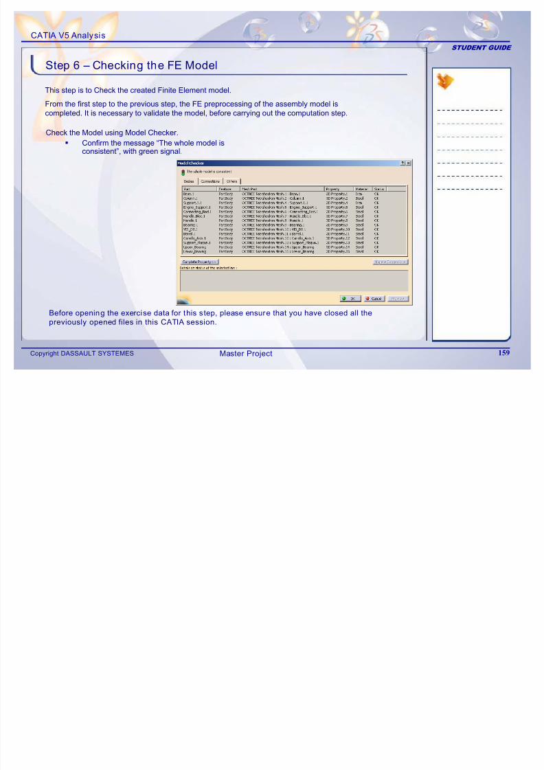
7/16/2019 Edu Cat en v5a Fb v5r19
http://slidepdf.com/reader/full/edu-cat-en-v5a-fb-v5r19 159/172
Copyright DASSAULT SYSTEMES 159
consistent , with green signal.
Before opening the exercise data for this step, please ensure that you have closed all the
previously opened files in this CATIA session.
Master Project
CATIA V5 Analysis
STUDENT GUIDE
Step 7 – Computing the FE Model
1. Specify the external storage paths.
Specify the external storage path forCATAnalysisResult file.
This step is to solve the model of the assembly.
Select the proper method for solution, based on the number of Degrees Of Freedom(DOF) for FE model.
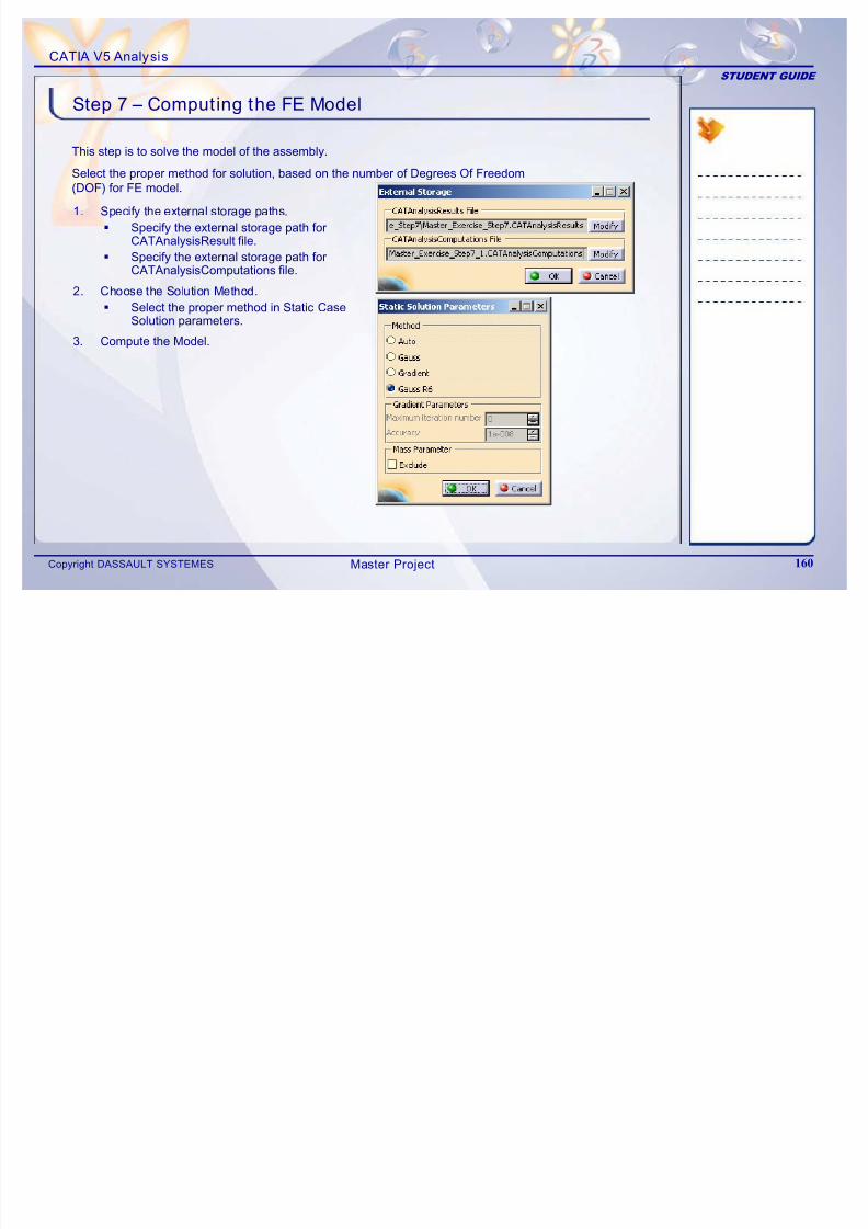
7/16/2019 Edu Cat en v5a Fb v5r19
http://slidepdf.com/reader/full/edu-cat-en-v5a-fb-v5r19 160/172
Copyright DASSAULT SYSTEMES 160
CATAnalysisResult file.
Specify the external storage path forCATAnalysisComputations file.
2. Choose the Solution Method.
Select the proper method in Static CaseSolution parameters.
3. Compute the Model.
Master Project
CATIA V5 Analysis
STUDENT GUIDE
Step 8 – Post-processing (1/3)
This step is to carry out the post processing and study the results.
1. Post-processing: Obtain different resultimages of the analysis.
Create Von Mises Stress (Nodalvalues) image.
Create Translational
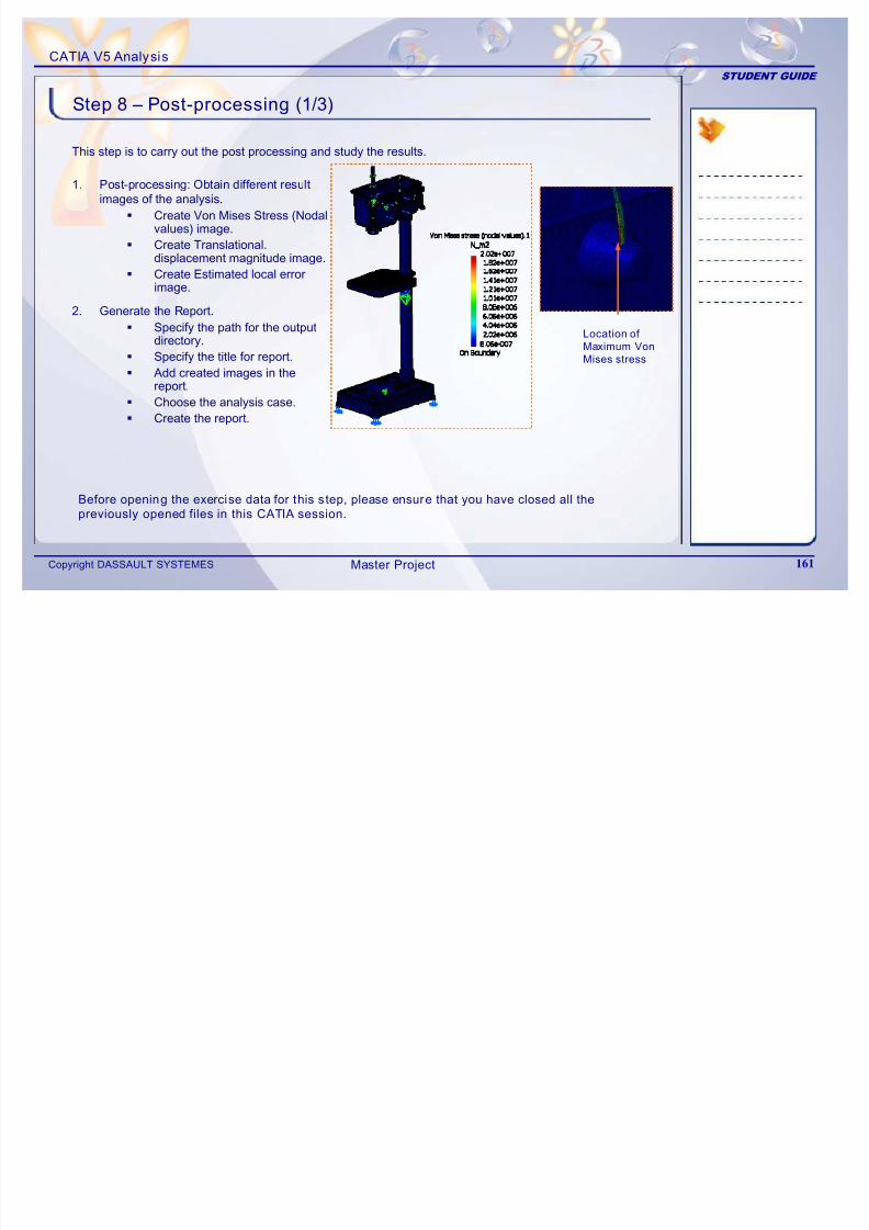
7/16/2019 Edu Cat en v5a Fb v5r19
http://slidepdf.com/reader/full/edu-cat-en-v5a-fb-v5r19 161/172
Copyright DASSAULT SYSTEMES 161
2. Generate the Report.
Specify the path for the outputdirectory.
Specify the title for report.
Add created images in thereport.
Choose the analysis case.
Create the report.
Create Translational.
displacement magnitude image. Create Estimated local error
image.
Location of
Maximum Von
Mises stress
Before opening the exercise data for this step, please ensure that you have closed all the
previously opened files in this CATIA session.
Master Project
CATIA V5 Analysis
STUDENT GUIDE
Step 8 – Post-processing (2/3)
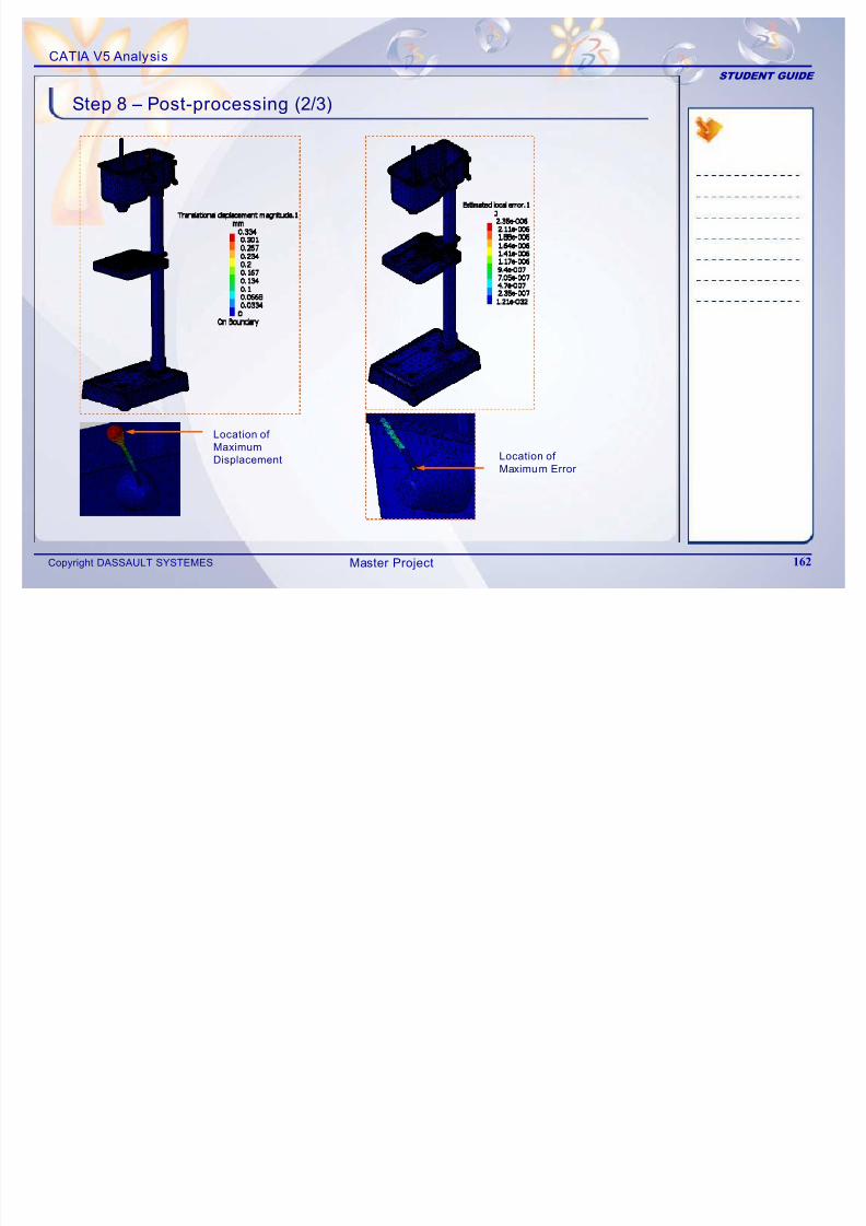
7/16/2019 Edu Cat en v5a Fb v5r19
http://slidepdf.com/reader/full/edu-cat-en-v5a-fb-v5r19 162/172
Copyright DASSAULT SYSTEMES 162
Location of
Maximum Error
Location of
Maximum
Displacement
Master Project
CATIA V5 Analysis
STUDENT GUIDE
Step 8 – Post-processing (3/3)
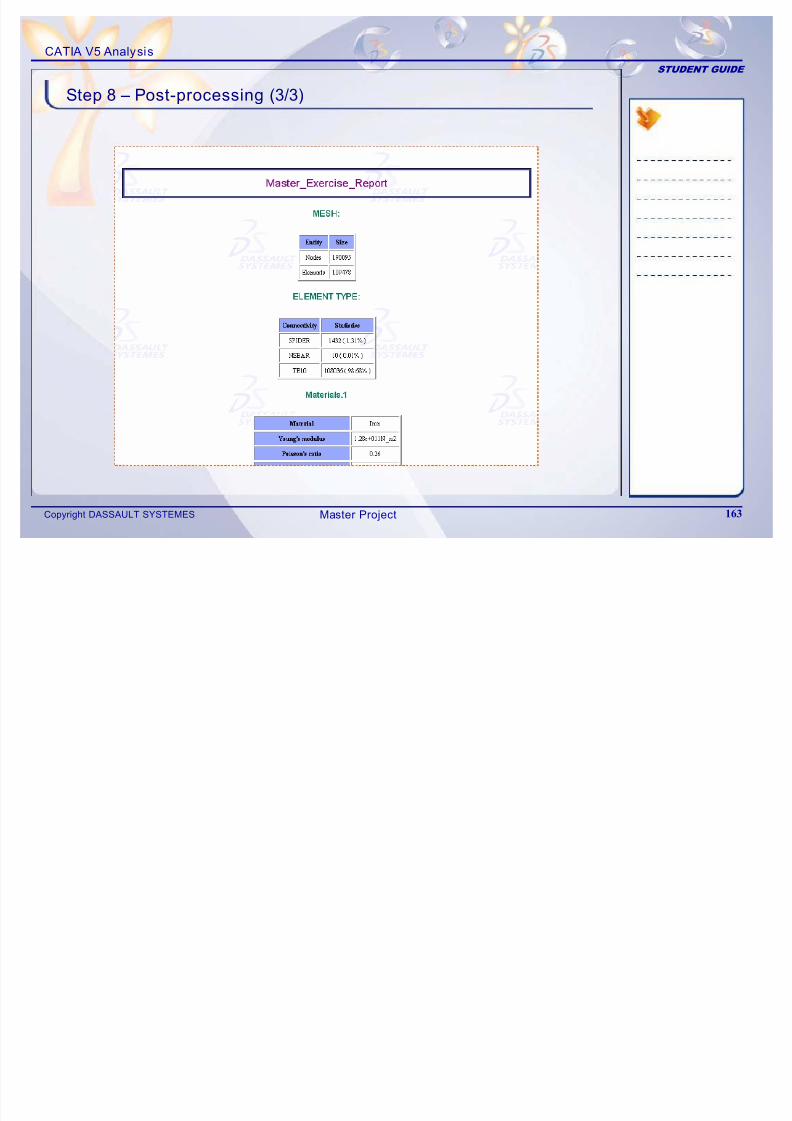
7/16/2019 Edu Cat en v5a Fb v5r19
http://slidepdf.com/reader/full/edu-cat-en-v5a-fb-v5r19 163/172
Copyright DASSAULT SYSTEMES 163Master Project
CATIA V5 Analysis
STUDENT GUIDE
F1
Shift F1
Shift F2
F3
Ctrl + Tab
Link to on-line documentation
Contextual help for an icon
Overview of the specification tree
Hide/Show the specification tree
Change CATIA V5 window
Ctrl + several selections
Shift + 2 selections
Al t F8
Multiple selection
Selection of all elements
between and including the 2
selected elements
Macros
Shortcuts
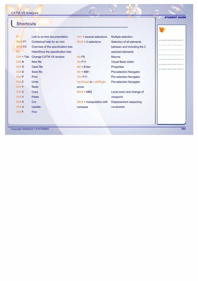
7/16/2019 Edu Cat en v5a Fb v5r19
http://slidepdf.com/reader/full/edu-cat-en-v5a-fb-v5r19 164/172
Copyright DASSAULT SYSTEMES 164
Ctrl + Tab
Ctrl N
Ctrl O
Ctrl S
Ctrl P
CtrlZ
Ctrl Y
Ctrl C
Ctrl V
Ctrl X
Ctrl UCtrl F
Change CATIA V5 window
New file
Open file
Save file
UndoRedo
Copy
Paste
Cut
UpdateFind
Al t F8
Al t F11
Al t + Enter
Al t + MB1
Ctrl F11
Up/Down or Left/Rightarrow
Shift + MB2
Shift + manipulation with
compass
Macros
Visual Basic editor
Properties
Pre-selection Navigator
Pre-selection Navigator
Pre-selection Navigator
Local zoom and change of
viewpoint
Displacement respecting
constraints
CATIA V5 Analysis
STUDENT GUIDE
Discretization: is the process of dividing the model
into a mesh of finite elements.
Degrees of Freedom (DOF): are the variablessolved during analysis, which for a pure structuralanalysis are the nodal displacements and rotations.
Generative Shape Design: is the workbench that
Free Vibration Analysis: is the analysis
in which the eigen frequencies are computedby referencing only masses. (constraints arenot taken into account)
Glossary
7/16/2019 Edu Cat en v5a Fb v5r19
http://slidepdf.com/reader/full/edu-cat-en-v5a-fb-v5r19 165/172
Copyright DASSAULT SYSTEMES 165
allows you to quickly model both simple andcomplex shapes, using wireframe and surfacefeatures.
Part Design: is the workbench dedicated fordesigning parts using the solid modeling approach.
Sag: is the perpendicular distance between the
actual geometry and the Element.
Course Meshing: is the meshing carried out byelements whose size is relatively larger.
Property: is an attribute such as color or a namethat can be assigned to any feature. All features can
be customized in both appearance and function.

7/16/2019 Edu Cat en v5a Fb v5r19
http://slidepdf.com/reader/full/edu-cat-en-v5a-fb-v5r19 166/172

7/16/2019 Edu Cat en v5a Fb v5r19
http://slidepdf.com/reader/full/edu-cat-en-v5a-fb-v5r19 167/172

7/16/2019 Edu Cat en v5a Fb v5r19
http://slidepdf.com/reader/full/edu-cat-en-v5a-fb-v5r19 168/172

7/16/2019 Edu Cat en v5a Fb v5r19
http://slidepdf.com/reader/full/edu-cat-en-v5a-fb-v5r19 169/172

7/16/2019 Edu Cat en v5a Fb v5r19
http://slidepdf.com/reader/full/edu-cat-en-v5a-fb-v5r19 170/172

7/16/2019 Edu Cat en v5a Fb v5r19
http://slidepdf.com/reader/full/edu-cat-en-v5a-fb-v5r19 171/172
Your everyday companion!
Companion is an essential tool which allows you to continuously enhance your skills and optimize your performance withDassaultSystemes products – right at your desk! The Companion includes theory, demonstrations, exercises, and methodologyrecommendations that enable you to learn proven ways to perform your daily tasks. Every release the Companion is updated by
DassaultSystemes experts to ensure that your knowledge remains current.For more details please visit www.3ds.com/education/
User Companion
CATIA | ENOVIA | DELMIA | SIMULIA | 3DVIA

7/16/2019 Edu Cat en v5a Fb v5r19
http://slidepdf.com/reader/full/edu-cat-en-v5a-fb-v5r19 172/172
Show them what you know!
Get Certif ied!
Research shows, and industry experts agree, that an IT certification increases your credibility in the Information Technologyworkplace. It provides tangible evidence to show that you have the proficiency to provide a higher level of support to your
employer. Are you ready to get certified and affirm the knowledge, skills, and experience you possess and gain a worldwiderecognized credential leading to success?
For complete details please visit http://www.pearsonvue.com/dassaultsystemes/