Embed Size (px)
Citation preview

PDH-Pro.com
396 Washington Street, Suite 159, Wellesley, MA 02481 Telephone – (508) 298-4787 www.PDH-Pro.com
This document is the course text. You may review this material at your leisure before or after you purchase the course. In order to obtain credit for this course, complete the following steps: 1) Log in to My Account and purchase the course. If you don’t have an account, go to New User to create an account. 2) After the course has been purchased, complete the quiz at your convenience. 3) A Certificate of Completion is available once you pass the exam (70% or greater). If a passing grade is not obtained, you may take the quiz as many times as necessary until a passing grade is obtained (up to one year from the purchase date). If you have any questions or technical difficulties, please call (508) 298-4787 or email us at [email protected].
Cathodic Protection
Course Number: EE-02-802
PDH: 4
Approved for: AK, AL, AR, GA, IA, IL, IN, KS, KY, MD, ME, MI, MN, MO, MS, MT, NC, ND, NE, NH, NJ, NM, NV, OH, OK, OR, PA, SC, SD, TN, TX, UT, VA, WI, WV, and WY
New Jersey Professional Competency Approval #24GP00025600 North Carolina Approved Sponsor #S-0695

UFC 3-570-02A 01 March 2005
UNIFIED FACILITIES CRITERIA (UFC)
CATHODIC PROTECTION
APPROVED FOR PUBLIC RELEASE; DISTRIBUTION UNLIMITED
UFC 3-570-02A 01 March 2005
1
UNIFIED FACILITIES CRITERIA (UFC)
CATHODIC PROTECTION
Any copyrighted material included in this UFC is identified at its point of use. Use of the copyrighted material apart from this UFC must have the permission of the copyright holder.
U.S. ARMY CORPS OF ENGINEERS (Preparing Activity)
NAVAL FACILITIES ENGINEERING COMMAND
AIR FORCE CIVIL ENGINEER SUPPORT AGENCY
Record of Changes (changes are indicated by \1\ ... /1/)
Change No. Date Location
This UFC supersedes TM 5-811-7, dated 22 April 1985. The format of this UFC does not conform to UFC 1-300-01; however, the format will be adjusted to conform at the next revision. The body of this UFC is a document of a different number.
UFC 3-570-02A 01 March 2005
2
FOREWORD\1\The Unified Facilities Criteria (UFC) system is prescribed by MIL-STD 3007 and provides planning, design, construction, sustainment, restoration, and modernization criteria, and applies to the Military Departments, the Defense Agencies, and the DoD Field Activities in accordance with USD(AT&L) Memorandum dated 29 May 2002. UFC will be used for all DoD projects and work for other customers where appropriate. All construction outside of the United States is also governed by Status of forces Agreements (SOFA), Host Nation Funded Construction Agreements (HNFA), and in some instances, Bilateral Infrastructure Agreements (BIA.) Therefore, the acquisition team must ensure compliance with the more stringent of the UFC, the SOFA, the HNFA, and the BIA, as applicable.
UFC are living documents and will be periodically reviewed, updated, and made available to users as part of the Services’ responsibility for providing technical criteria for military construction. Headquarters, U.S. Army Corps of Engineers (HQUSACE), Naval Facilities Engineering Command (NAVFAC), and Air Force Civil Engineer Support Agency (AFCESA) are responsible for administration of the UFC system. Defense agencies should contact the preparing service for document interpretation and improvements. Technical content of UFC is the responsibility of the cognizant DoD working group. Recommended changes with supporting rationale should be sent to the respective service proponent office by the following electronic form: Criteria Change Request (CCR). The form is also accessible from the Internet sites listed below.
UFC are effective upon issuance and are distributed only in electronic media from the following source:
� Whole Building Design Guide web site http://dod.wbdg.org/.
Hard copies of UFC p rinted from electronic media should be checked against the current electronic version prior to use to ensure that they are current.
AUTHORIZED BY:
______________________________________DONALD L. BASHAM, P.E. Chief, Engineering and Construction U.S. Army Corps of Engineers
______________________________________DR. JAMES W WRIGHT, P.E. Chief Engineer Naval Facilities Engineering Command
______________________________________KATHLEEN I. FERGUSON, P.E. The Deputy Civil Engineer DCS/Installations & Logistics Department of the Air Force
______________________________________Dr. GET W. MOY, P.E. Director, Installations Requirements and Management Office of the Deputy Under Secretary of Defense (Installations and Environment)
a/b
TM 5-811-7
REPRODUCTION AUTHORIZATION/RESTRICTIONS
This manual has been prepared by or for the Government and, except to the extent indicated below, is public property and not subjectto copyright.Copyrighted material included in the manual has been used with the knowledge and permission of the proprietors and is acknowledgedas such at point of use. Anyone wishing to make further use of any copyrighted material, by itself and apart from this text should seeknecessary permission directly from the proprietors.Reprints or republications of this manual should include a credit substantially as follows: “Department of the Army, USA, TechnicalManual TM 5-811-7, Electrical Protection, Cathodic Protection.”If the reprint or republication includes copyrighted material, the credit should also state: “Anyone wishing to make further use ofcopyrighted material, by itself and apart from this text, should seek necessary permission directly from the proprietors.”
i
*TM 5-811-7
Technical Manual HEADQUARTERSDEPARTMENT OF THE ARMY
No. 5-811-7 WASHINGTON, D.C. 22 April 1985
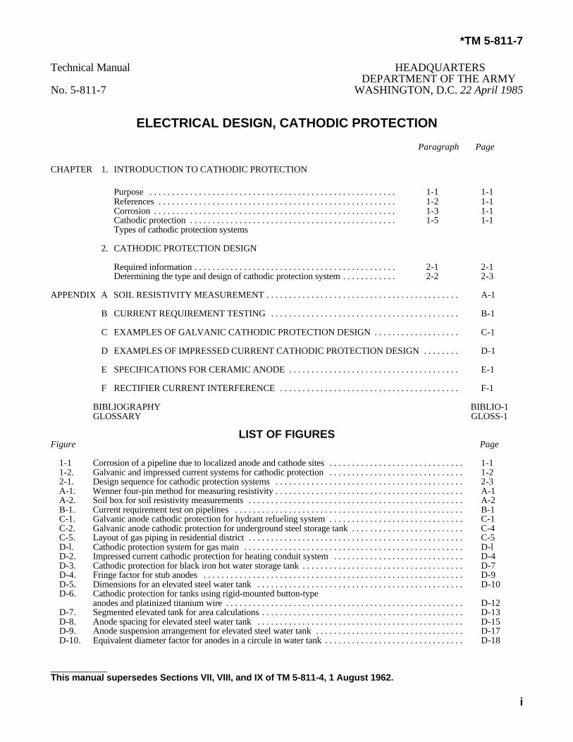
ELECTRICAL DESIGN, CATHODIC PROTECTIONParagraph Page
CHAPTER 1. INTRODUCTION TO CATHODIC PROTECTION
Purpose . . . . . . . . . . . . . . . . . . . . . . . . . . . . . . . . . . . . . . . . . . . . . . . . . . . . . . . 1-1 1-1References . . . . . . . . . . . . . . . . . . . . . . . . . . . . . . . . . . . . . . . . . . . . . . . . . . . . . 1-2 1-1Corrosion . . . . . . . . . . . . . . . . . . . . . . . . . . . . . . . . . . . . . . . . . . . . . . . . . . . . . . 1-3 1-1Cathodic protection . . . . . . . . . . . . . . . . . . . . . . . . . . . . . . . . . . . . . . . . . . . . . . 1-5 1-1Types of cathodic protection systems
2. CATHODIC PROTECTION DESIGN
Required information . . . . . . . . . . . . . . . . . . . . . . . . . . . . . . . . . . . . . . . . . . . . . 2-1 2-1Determining the type and design of cathodic protection system . . . . . . . . . . . . 2-2 2-3
APPENDIX A SOIL RESISTIVITY MEASUREMENT . . . . . . . . . . . . . . . . . . . . . . . . . . . . . . . . . . . . . . . . . . . A-1
B CURRENT REQUIREMENT TESTING . . . . . . . . . . . . . . . . . . . . . . . . . . . . . . . . . . . . . . . . . . B-1
C EXAMPLES OF GALVANIC CATHODIC PROTECTION DESIGN . . . . . . . . . . . . . . . . . . . C-1
D EXAMPLES OF IMPRESSED CURRENT CATHODIC PROTECTION DESIGN . . . . . . . . D-1
E SPECIFICATIONS FOR CERAMIC ANODE . . . . . . . . . . . . . . . . . . . . . . . . . . . . . . . . . . . . . . E-1
F RECTIFIER CURRENT INTERFERENCE . . . . . . . . . . . . . . . . . . . . . . . . . . . . . . . . . . . . . . . . F-1
BIBLIOGRAPHY BIBLIO-1GLOSSARY GLOSS-1
LIST OF FIGURESFigure Page
1-1 Corrosion of a pipeline due to localized anode and cathode sites . . . . . . . . . . . . . . . . . . . . . . . . . . . . . . 1-11-2. Galvanic and impressed current systems for cathodic protection . . . . . . . . . . . . . . . . . . . . . . . . . . . . . . 1-22-1. Design sequence for cathodic protection systems . . . . . . . . . . . . . . . . . . . . . . . . . . . . . . . . . . . . . . . . . . 2-3A-1. Wenner four-pin method for measuring resistivity . . . . . . . . . . . . . . . . . . . . . . . . . . . . . . . . . . . . . . . . . . A-1A-2. Soil box for soil resistivity measurements . . . . . . . . . . . . . . . . . . . . . . . . . . . . . . . . . . . . . . . . . . . . . . . . A-2B-1. Current requirement test on pipelines . . . . . . . . . . . . . . . . . . . . . . . . . . . . . . . . . . . . . . . . . . . . . . . . . . . B-1C-1. Galvanic anode cathodic protection for hydrant refueling system . . . . . . . . . . . . . . . . . . . . . . . . . . . . . . C-1C-2. Galvanic anode cathodic protection for underground steel storage tank . . . . . . . . . . . . . . . . . . . . . . . . . C-4C-5. Layout of gas piping in residential district . . . . . . . . . . . . . . . . . . . . . . . . . . . . . . . . . . . . . . . . . . . . . . . . C-5D-l. Cathodic protection system for gas main . . . . . . . . . . . . . . . . . . . . . . . . . . . . . . . . . . . . . . . . . . . . . . . . . D-lD-2. Impressed current cathodic protection for heating conduit system . . . . . . . . . . . . . . . . . . . . . . . . . . . . . D-4D-3. Cathodic protection for black iron hot water storage tank . . . . . . . . . . . . . . . . . . . . . . . . . . . . . . . . . . . . D-7D-4. Fringe factor for stub anodes . . . . . . . . . . . . . . . . . . . . . . . . . . . . . . . . . . . . . . . . . . . . . . . . . . . . . . . . . . D-9D-5. Dimensions for an elevated steel water tank . . . . . . . . . . . . . . . . . . . . . . . . . . . . . . . . . . . . . . . . . . . . . . D-10D-6. Cathodic protection for tanks using rigid-mounted button-type
anodes and platinized titanium wire . . . . . . . . . . . . . . . . . . . . . . . . . . . . . . . . . . . . . . . . . . . . . . . . . . . . . D-12D-7. Segmented elevated tank for area calculations . . . . . . . . . . . . . . . . . . . . . . . . . . . . . . . . . . . . . . . . . . . . . D-13D-8. Anode spacing for elevated steel water tank . . . . . . . . . . . . . . . . . . . . . . . . . . . . . . . . . . . . . . . . . . . . . . D-15D-9. Anode suspension arrangement for elevated steel water tank . . . . . . . . . . . . . . . . . . . . . . . . . . . . . . . . . D-17D-10. Equivalent diameter factor for anodes in a circule in water tank . . . . . . . . . . . . . . . . . . . . . . . . . . . . . . . D-18
____________This manual supersedes Sections VII, VIII, and IX of TM 5-811-4, 1 August 1962.

ii
TM 5-811-7
LIST OF FIGURES (CONT’d)
Paragraph Page
D-l 1. Elevated steel water tank showing rectifier and anode arrangement . . . . . . . . . . . . . . . . . . . . . . . . . . . . D-24D-12. Hand hole and anode suspension detail for elevated water tank . . . . . . . . . . . . . . . . . . . . . . . . . . . . . . . 9-25D-13. Riser anode suspension detail for elevated water tank . . . . . . . . . . . . . . . . . . . . . . . . . . . . . . . . . . . . . . . 9-25E-1. Ceramic anode specifications . . . . . . . . . . . . . . . . . . . . . . . . . . . . . . . . . . . . . . . . . . . . . . . . . . . . . . . . . . E-lF-1. Structure-to-soil potential versus distance from foreign structure . . . . . . . . . . . . . . . . . . . . . . . . . . . . . . F-1F-2. Cathodic interference testing . . . . . . . . . . . . . . . . . . . . . . . . . . . . . . . . . . . . . . . . . . . . . . . . . . . . . . . . . . F-2
LIST OF TABLES
Table Page
2-1. Corrosivity of soils on steel based on soil resistivity . . . . . . . . . . . . . . . . . . . . . . . . . . . . . . . . . . . . . . . . 2-1 2-2. Typical current density requirements for cathodic protection of uncoated steel . . . . . . . . . . . . . . . . . . . 2-2 2-3. Weights and dimensions of selected high-potential magnesium-alloy anodes . . . . . . . . . . . . . . . . . . . . . 2-4 2-4. Weights and dimensions of selected circular high-silicon chromium-bearing cast iron anodes . . . . . . . 2-6 2-5. Shape functions (K) for impressed current cathodic protection anodes where L is the effective
anode length and d is the anode/backfill diameter . . . . . . . . . . . . . . . . . . . . . . . . . . . . . . . . . . . . . . . . . . 2-6 2-6 Anode paralleling factors (P) for various numbers of anodes (N) installed in parallel . . . . . . . . . . . . . . 2-6C-1 Outside area of liquid fuel pipes . . . . . . . . . . . . . . . . . . . . . . . . . . . . . . . . . . . . . . . . . . . . . . . . . . . . . . . . C-2C-2. Requirements for anode spacing . . . . . . . . . . . . . . . . . . . . . . . . . . . . . . . . . . . . . . . . . . . . . . . . . . . . . . . . C-5C-3. Dimensions for finding outside area of pipe . . . . . . . . . . . . . . . . . . . . . . . . . . . . . . . . . . . . . . . . . . . . . . . C-6C-4. Galvanic anode size factor If) . . . . . . . . . . . . . . . . . . . . . . . . . . . . . . . . . . . . . . . . . . . . . . . . . . . . . . . . . . C-7C-5. Structure potential factor (y) . . . . . . . . . . . . . . . . . . . . . . . . . . . . . . . . . . . . . . . . . . . . . . . . . . . . . . . . . . . C-7C-6. Dimensions for finding anode division . . . . . . . . . . . . . . . . . . . . . . . . . . . . . . . . . . . . . . . . . . . . . . . . . . . C-8D-1. Dimensions for finding steam conduit area: heat distribution system . . . . . . . . . . . . . . . . . . . . . . . . . . . D-5D-2. Dimensions for finding condensate return conduit area: heat distribution system . . . . . . . . . . . . . . . . . . D-5D-3. Conduit area: heat distribution system . . . . . . . . . . . . . . . . . . . . . . . . . . . . . . . . . . . . . . . . . . . . . . . . . . . D-6D-4. Anode division: heat distribution system . . . . . . . . . . . . . . . . . . . . . . . . . . . . . . . . . . . . . . . . . . . . . . . . . D-7D-5. Technical data: commonly used HSCBCI anodes . . . . . . . . . . . . . . . . . . . . . . . . . . . . . . . . . . . . . . . . . . D-1
TM 5-811-7
1-1
CHAPTER 1INTRODUCTION TO CATHODIC PROTECTION
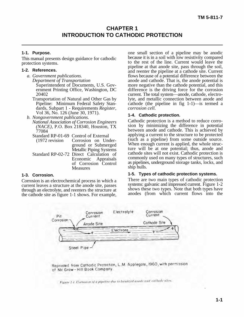
1-1. Purpose. one small section of a pipeline may be anodicThis manual presents design guidance for cathodicprotection systems.1-2. References.
a. Government publications. flows because of a potential difference between theDepartment of Transportation anode and cathode. That is, the anode potential is
Superintendent of Documents, U.S. Gov- more negative than the cathode potential, and thisernment Printing Office, Washington, DC difference is the driving force for the corrosion20402 current. The total system—anode, cathode, electro-
Transportation of Natural and Other Gas by lyte, and metallic connection between anode andPipeline: Minimum Federal Safety Stan- cathode (the pipeline in fig 1-1)—is termed adards, Subpart 1 - Requirements Register, corrosion cell.Vol 36, No. 126 (June 30, 1971).
b. Nongovernment publications.National Association of Corrosion Engineers
(NACE), P.O. Box 218340, Houston, TX77084
Standard RP-01-69 Control of External (1972 revision Corrosion on Under-
ground or SubmergedMetallic Piping Systems
Standard RP-02-72 Direct Calculation ofEconomic Appraisalsof Corrosion ControlMeasures
1-3. Corrosion.Corrosion is an electrochemical process in which acurrent leaves a structure at the anode site, passesthrough an electrolyte, and reenters the structure atthe cathode site as figure 1-1 shows. For example,
because it is in a soil with low resistivity comparedto the rest of the line. Current would leave thepipeline at that anode site, pass through the soil,and reenter the pipeline at a cathode site. Current
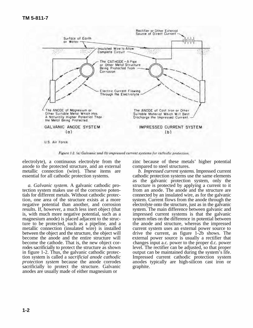
1-4. Cathodic protection.Cathodic protection is a method to reduce corro-sion by minimizing the difference in potentialbetween anode and cathode. This is achieved byapplying a current to the structure to be protected(such as a pipeline) from some outside source.When enough current is applied, the whole struc-ture will be at one potential; thus, anode andcathode sites will not exist. Cathodic protection iscommonly used on many types of structures, suchas pipelines, underground storage tanks, locks, andship hulls.1-5. Types of cathodic protection systems.There are two main types of cathodic protectionsystems: galvanic and impressed current. Figure 1-2shows these two types. Note that both types haveanodes (from which current flows into the
TM 5-811-7
1-2
electrolyte), a continuous electrolyte from the zinc because of these metals’ higher potentialanode to the protected structure, and an external compared to steel structures.metallic connection (wire). These items are b. Impressed current systems. Impressed currentessential for all cathodic protection systems. cathodic protection systems use the same elements
a. Galvanic system. A galvanic cathodic pro- structure is protected by applying a current to ittection system makes use of the corrosive poten- from an anode. The anode and the structure aretials for different metals. Without cathodic protec- connected by an insulated wire, as for the galvaniction, one area of the structure exists at a more system. Current flows from the anode through thenegative potential than another, and corrosion electrolyte onto the structure, just as in the galvanicresults. If, however, a much less inert object (that system. The main difference between galvanic andis, with much more negative potential, such as a impressed current systems is that the galvanicmagnesium anode) is placed adjacent to the struc- system relies on the difference in potential betweenture to be protected, such as a pipeline, and a the anode and structure, whereas the impressedmetallic connection (insulated wire) is installed current system uses an external power source tobetween the object and the structure, the object will drive the current, as figure 1-2b shows. Thebecome the anode and the entire structure will external power source is usually a rectifier thatbecome the cathode. That is, the new object cor- changes input a.c. power to the proper d.c. powerrodes sacrificially to protect the structure as shown level. The rectifier can be adjusted, so that properin figure 1-2. Thus, the galvanic cathodic protec- output can be maintained during the system’s life.tion system is called a sacrificial anode cathodic Impressed current cathodic protection systemprotection system because the anode corrodes anodes typically are high-silicon cast iron orsacrificially to protect the structure. Galvanic graphite.anodes are usually made of either magnesium or
as the galvanic protection system, only the
TM 5-811-7
2-1
CHAPTER 2CATHODIC PROTECTION DESIGN
2-1. Required information. resistivity increases, the corrosion rate decreasesBefore deciding which type, galvanic or impressedcurrent, cathodic protection system will be usedand before the system is designed, certain prelimi-nary data must be gathered.
a. Physical dimensions of structure to be pro-tected. One important element in designing acathodic protection system is the structure's phys-ical dimensions (for example, length, width, height,and diameter). These data are used to calculate thesurface area to be protected.
b. Drawing of structure to be protected. Theinstallation drawings must include sizes, shapes,material type, and locations of parts of the structureto be protected.
c. Electrical isolation. If a structure is to beprotected by the cathodic system, it must be elec-trically connected to the anode, as figure 1-2shows. Sometimes parts of a structure or systemare electrically isolated from each other by insula-tors. For example, in a gas pipeline distributionsystem, the inlet pipe to each building mightcontain an electric insulator to isolate inhousepiping from the pipeline. Also, an electricalinsulator might be used at a valve along the pipelineto electrically isolate one section of the systemfrom another. Since each electrically isolated partof a structure would need its own cathodicprotection, the locations of these insulators must bedetermined.
d. Short circuits. All short circuits must beeliminated from existing and new cathodic protec-tion systems. A short circuit can occur when onepipe system contacts another, causing interferencewith the cathodic protection system. Whenupdating existing systems, eliminating short circuitswould be a necessary first step.
e. Corrosion history of structures in the area.Studying the corrosion history in the area canprove very helpful when designing a cathodic pro-tection system. The study should reinforce predic-tions for corrosivity of a given structure and itsenvironment; in addition, it may reveal abnormalconditions not otherwise suspected. Facilities per-sonnel can be a good source of information forcorrosion history.
f. Electrolyte resistivity survey. A structure'scorrosion rate is proportional to the electrolyteresistivity. Without cathodic protection, as electro-lyte resistivity decreases, more current is allowed toflow from the structure into the electrolyte; thus,the structure corrodes more rapidly. As electrolyte
(table 2-1). Resistivity can be measured either in alaboratory or at the site with the proper instru-ments. Appendix A explains the methods andequipment needed to complete a soil resistivitysurvey. The resistivity data will be used to calculatethe sizes of anodes and rectifier required indesigning the cathodic protection system.
Table 2-1. Corrosivity of soils on steel based on soil resistivity
Soil resistivity range (ohm-cm) Corrosivity
0 to 2000 Severe2000 to 10,000 Moderate to severe10,000 to 30,000 MildAbove 30,000 Not likely
U.S. Air Force.
g. Electrolyte pH survey. Corrosion is also pro-portional to electrolyte pH (see glossary for defini-tion of pH and other terms). In general, steel'scorrosion rate increases as pH decreases when soilresistivity remains constant.
h. Structure versus electrolyte potential survey.For existing structures, the potential between thestructure and the electrolyte will give a directindication of the corrosivity. According to NACEStandard No. RP-01, the potential requirement forcathodic protection is a negative (cathodic) poten-tial of at least 0.85 volt as measured between thestructure and a saturated copper-copper sulfatereference electrode in contact with the electrolyte.A potential which is less negative than -0.85 voltwould probably be corrosive, with corrosivity in-creasing as the negative value decreases (becomesmore positive).
i. Current requirement. A critical part of designcalculations for cathodic protection systems onexisting structures is the amount of current re-quired per square foot (called current density) tochange the structure’s potential to -0.85 volt. Thecurrent density required to shift the potential indi-cates the structure's surface condition. A wellcoated structure (for example, a pipeline wellcoated with coal-tar epoxy) will require a very lowcurrent density (about 0.05 milliampere per squarefoot); an uncoated structure would require highcurrent density (about 10 milliamperes per squarefoot). The average current density required forcathodic protection is 2 milliamperes per square
TM 5-811-7
2-2
foot of bare area. The amount of current required Table 2-2. Typical current density requirements for cathodicfor complete cathodic protection can be determinedthree ways:
—An actual test on existing structures usinga temporary cathodic protection setup.
—A theoretical calculation based on coatingefficiency.
—An estimate of current requirements usingtables based on field experience.
(1) The second and third methods above canbe used on both existing and new structures.Appendix B contains a detailed review of currentrequirement testing.
(2) Current requirements can be calculatedbased on coating efficiency and current density(current per square foot) desired. The efficiency ofthe coating as supplied will have a direct effect onthe total current requirement, as equation 2-1shows:
I = (A)(I•)(1.0-CE), (eq 2-1)
where I is total protective current, A is total struc-ture surface area in square feet, I• is required cur-rent density, and CE is coating efficiency. Equation2-1 may be used when a current requirement test isnot possible, as on new structures, or as a check ofthe current requirement test on existing structures.Coating efficiency is directly affected by the type ofcoating used and by quality control during coatingapplication. The importance of coating efficiency isevident in the fact that a bare structure may require100,000 times as much current as would the samestructure if it were well coated.
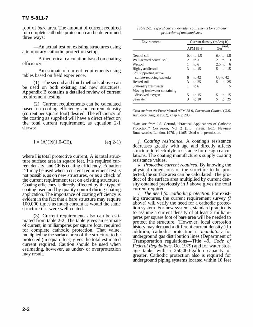
(3) Current requirements also can be esti-mated from table 2-2. The table gives an estimateof current, in milliamperes per square foot, requiredfor complete cathodic protection. That value,multiplied by the surface area of the structure to beprotected (in square feet) gives the total estimatedcurrent required. Caution should be used whenestimating, however, as under- or overprotectionmay result.
protection of uncoated steel
Environment Current density (mA/sq ft)rardAFM 88-9 Gera b
Neutral soil 0.4 to 1.5 0.4 to 1.5Well aerated neutral soil 2 to 3 2 to 3Wetsoil 1 to 6 2.5 to 6Highly acidic soil 3 to 15 5 to 15Soil supporting active sulfate-reducing bacteria 6 to 42 Up to 42Heated soil 3 to 25 5 to 25Stationary freshwater 1 to 6 5Moving freshwater containing dissolved oxygen 5 to 15 5 to 15Seawater 3 to 10 5 to 25
Data are from Air Force Manual AFM 88-9, Corrosion Control (U.S.a
Air Force, August 1962), chap 4, p 203.
Data are from J.S. Gerrard, “Practical Applications of Cathodicb
Protection," Corrosion, Vol 2 (L.L. Shreir, Ed.), Newnes-Butterworths, London, 1976, p 11:65. Used with permission.
j. Coating resistance. A coating's resistancedecreases greatly with age and directly affectsstructure-to-electrolyte resistance for design calcu-lations. The coating manufacturers supply coatingresistance values.
k. Protective current required. By knowing thephysical dimensions of the structure to be pro-tected, the surface area can be calculated. The pro-duct of the surface area multiplied by current den-sity obtained previously in I above gives the totalcurrent required.
l. The need for cathodic protection. For exist-ing structures, the current requirement survey (Iabove) will verify the need for a cathodic protec-tion system. For new systems, standard practice isto assume a current density of at least 2 milliam-peres per square foot of bare area will be needed toprotect the structure. (However, local corrosionhistory may demand a different current density.) Inaddition, cathodic protection is mandatory forunderground gas distribution lines (Department ofTransportation regulations—Title 49, Code ofFederal Regulations, Oct 1979) and for water stor-age tanks with a 250,000-gallon capacity orgreater. Cathodic protection also is required forunderground piping systems located within 10 feet
TM 5-811-7
2-3
of steel reinforced concrete because galvanic corro- when this is not clear, the criterion used mostsion will occur between the steel rebar and the widely is based on current density required and soilpipeline. resistivity. If the soil resistivity is low (less than
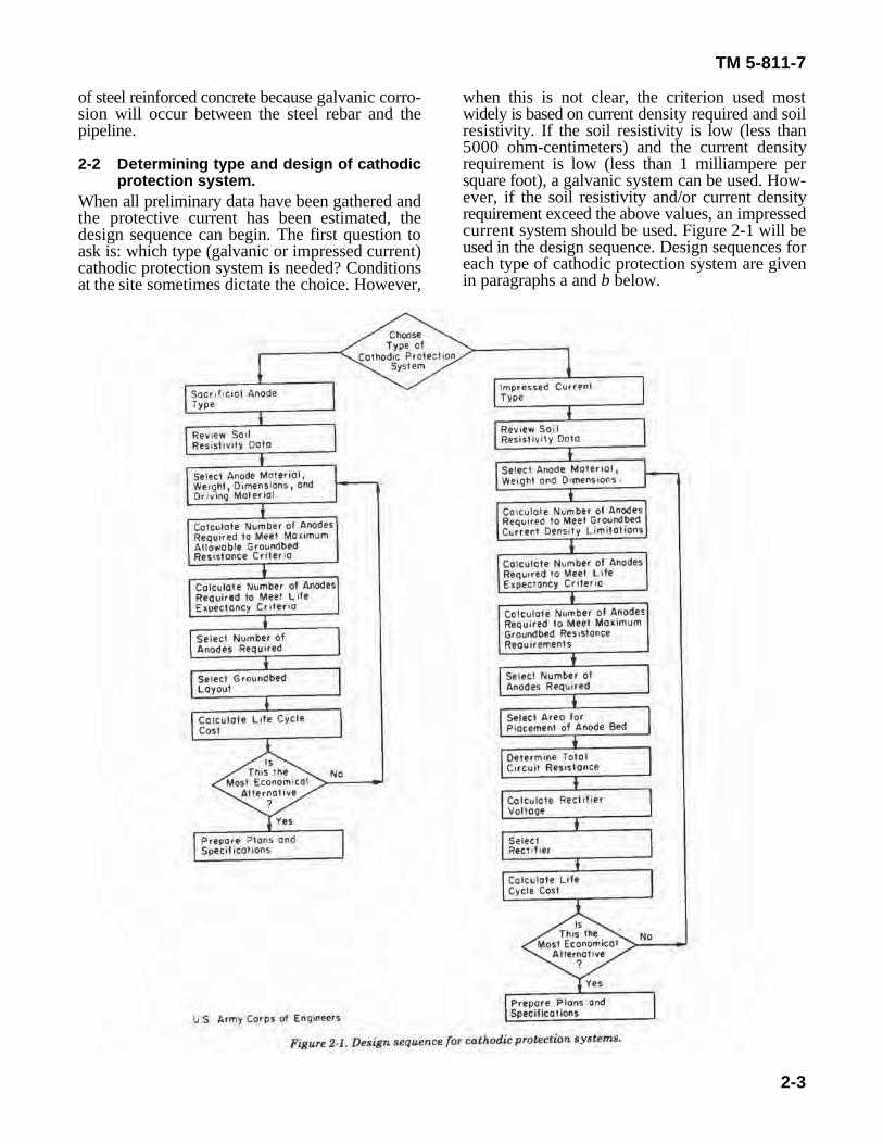
2-2 Determining type and design of cathodic requirement is low (less than 1 milliampere perprotection system. square foot), a galvanic system can be used. How-
When all preliminary data have been gathered andthe protective current has been estimated, thedesign sequence can begin. The first question toask is: which type (galvanic or impressed current)cathodic protection system is needed? Conditionsat the site sometimes dictate the choice. However,
5000 ohm-centimeters) and the current density
ever, if the soil resistivity and/or current densityrequirement exceed the above values, an impressedcurrent system should be used. Figure 2-1 will beused in the design sequence. Design sequences foreach type of cathodic protection system are givenin paragraphs a and b below.
RT • • EI
,
Rc • RA
,
TM 5-811-7
2-4
(eq 2-3)
(eq 2-4)
a. Sacrificial anode (galvanic) cathodic protec-tion system design. The following eight steps arerequired when designing galvanic cathodic pro-tection systems. Appendix C gives examples ofgalvanic cathodic protection designs.
(1) Review soil resistivity. The site of lowestresistivity will likely be used for anode location tominimize anode-to-electrolyte resistivity. In addi-tion, if resistivity variations are not significant, theaverage resistivity will be used for designcalculations.
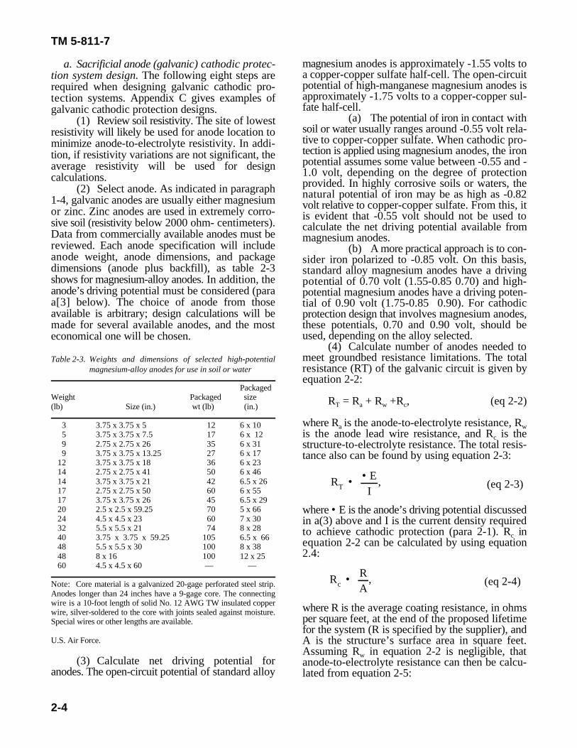
(2) Select anode. As indicated in paragraph1-4, galvanic anodes are usually either magnesiumor zinc. Zinc anodes are used in extremely corro-sive soil (resistivity below 2000 ohm- centimeters).Data from commercially available anodes must bereviewed. Each anode specification will includeanode weight, anode dimensions, and packagedimensions (anode plus backfill), as table 2-3shows for magnesium-alloy anodes. In addition, theanode’s driving potential must be considered (paraa[3] below). The choice of anode from thoseavailable is arbitrary; design calculations will bemade for several available anodes, and the mosteconomical one will be chosen.
Table 2-3. Weights and dimensions of selected high-potentialmagnesium-alloy anodes for use in soil or water
PackagedWeight Packaged size(lb) Size (in.) wt (lb) (in.)
3 3.75 x 3.75 x 5 12 6 x 10⁵ 3.75 x 3.75 x 7.5 17 6 x 129 2.75 x 2.75 x 26 35 6 x 319 3.75 x 3.75 x 13.25 27 6 x 17
12 3.75 x 3.75 x 18 36 6 x 2314 2.75 x 2.75 x 41 50 6 x 4614 3.75 x 3.75 x 21 42 6.5 x 2617 2.75 x 2.75 x 50 60 6 x 5517 3.75 x 3.75 x 26 45 6.5 x 2920 2.5 x 2.5 x 59.25 70 5 x 6624 4.5 x 4.5 x 23 60 7 x 3032 5.5 x 5.5 x 21 74 8 x 2840 3.75 x 3.75 x 59.25 105 6.5 x 6648 5.5 x 5.5 x 30 100 8 x 3848 8 x 16 100 12 x 2560 4.5 x 4.5 x 60 — —
Note: Core material is a galvanized 20-gage perforated steel strip.Anodes longer than 24 inches have a 9-gage core. The connectingwire is a 10-foot length of solid No. 12 AWG TW insulated copperwire, silver-soldered to the core with joints sealed against moisture.Special wires or other lengths are available.
U.S. Air Force.
(3) Calculate net driving potential foranodes. The open-circuit potential of standard alloy
magnesium anodes is approximately -1.55 volts toa copper-copper sulfate half-cell. The open-circuitpotential of high-manganese magnesium anodes isapproximately -1.75 volts to a copper-copper sul-fate half-cell.
(a) The potential of iron in contact withsoil or water usually ranges around -0.55 volt rela-tive to copper-copper sulfate. When cathodic pro-tection is applied using magnesium anodes, the ironpotential assumes some value between -0.55 and -1.0 volt, depending on the degree of protectionprovided. In highly corrosive soils or waters, thenatural potential of iron may be as high as -0.82volt relative to copper-copper sulfate. From this, itis evident that -0.55 volt should not be used tocalculate the net driving potential available frommagnesium anodes.
(b) A more practical approach is to con-sider iron polarized to -0.85 volt. On this basis,standard alloy magnesium anodes have a drivingpotential of 0.70 volt (1.55-0.85 0.70) and high-potential magnesium anodes have a driving poten-tial of 0.90 volt (1.75-0.85 0.90). For cathodicprotection design that involves magnesium anodes,these potentials, 0.70 and 0.90 volt, should beused, depending on the alloy selected.
(4) Calculate number of anodes needed tomeet groundbed resistance limitations. The totalresistance (RT) of the galvanic circuit is given byequation 2-2:
R = R + R +R , (eq 2-2)T a w c
where R is the anode-to-electrolyte resistance, Ra wis the anode lead wire resistance, and R is thecstructure-to-electrolyte resistance. The total resis-tance also can be found by using equation 2-3:
where • E is the anode’s driving potential discussedin a(3) above and I is the current density requiredto achieve cathodic protection (para 2-1). R incequation 2-2 can be calculated by using equation2.4:
where R is the average coating resistance, in ohmsper square feet, at the end of the proposed lifetimefor the system (R is specified by the supplier), andA is the structure’s surface area in square feet.Assuming R in equation 2-2 is negligible, thatwanode-to-electrolyte resistance can then be calcu-lated from equation 2-5:
N • (0.0052)(• )(Ra)(L)
[1n 8Ld
• 1],
N • (L) (I)49.3 (W)
,
A •AT
N,
TM 5-811-7
2-5
(eq 2-6)
(eq 2-7)
(eq 2-8)
R = R - R , (eq 2-5) choices to find the one with minimal life-cycle cost.a T c
which gives the maximum allowable groundbed the design procedure has been done for severalresistance; this will dictate the minimum number of different anodes and the final anode has beenanodes required (as number of anodes decreases, chosen, plans and specifications can be completed.groundbed resistance increases). To calculate the b. Impressed current cathodic protection systemnumber of anodes required, equation 2-6 is used: design. Thirteen steps are required when designing
where N is the number of anodes, is the soil systems, this information will contribute to bothresistivity in ohms, R is the maximum allowable design calculations and location of anode ground-agroundbed resistance in ohms (as computed in eq bed.2-5), L is the length of the backfill column in feet (2) Review current requirement test. The re-(specified by supplier), and d is the diameter of the quired current will be used throughout the designbackfill column in feet (specified by supplier). calculations. The calculated current required to
(5) Calculate number of anodes for system's protect 1 square foot of bare pipe should agreelife expectancy. Each cathodic protection system with the values in table 2-2.will be designed to protect a structure for a given (3) Select anode. As with the galvanic sys-number of years. To meet this lifetime requirement, tem, the choice of anode is arbitrary at this time;the number of anodes (N) must be calculated using economy will determine which anode is best. Tableequation 2-7: 2-4 gives common anode sizes and specifications.
where L expected lifetime in years, W is weight (in underground steel structure, the auxiliary anodespounds) of one anode, and I is the current density often are surrounded by a carbonaceous backfill.required to protect the structure (in milliamperes). Backfill materials commonly used include coal coke
(6) Select number of anodes to be used. The breeze, calcined petroleum coke breeze, and naturalgreater value of equation 2-6 or 2-7 will be used as graphite particles. The backfill serves three basicthe number of anodes needed for the system. functions: (a) it decreases the anode-to-earth
(7) Select groundbed layout. When the re- resistance by increasing the anode's effective size,quired number of anodes has been calculated, the (b) it extends the system's operational life byarea to be protected by each anode is calculated by providing additional anode material, and (c) itequation 2-8: provides a uniform environment around the anode,
where A is area to be protected by one anode, A HSCBCI anodes, the ceramic anode should be con-Tis total surface area to be protected, and N is the sidered as a possible alternative for long-termtotal number of anodes to be used. For galvanic cathodic protection of water storage tanks andcathodic protection systems, the anodes should be underground pipes in soils with resistivities lessspaced equally along the structure to be protected. than 5000 ohm-centimeters. The ceramic anode
(8) Calculate life-cycle cost for proposed de- consumption rate is 0.0035 ounce per ampere-yearsign. NACE Standard RP-02 should be used to compared to 1 pound per ampere-year for HSCBCIcalculate the system's life-cycle cost. The design anodes. Appendix E gives the design and specifi-process should be done for several different anode cations for the ceramic anode.
(9) Prepare plans and specifications. When
impressed current cathodic protection systems.Appendix D gives examples of impressed currentcathodic protection designs.
(1) Review soil resistivity. As with galvanic
The anodes used most often are made of high-silicon chromium-bearing cast-iron (HSCBCI).When impressed current-type cathodic protectionsystems are used to mitigate corrosion on an
minimizing deleterious localized attack. The car-bonaceous backfill, however, cannot be expected toincrease the groundbed life expectancy unless it iswell compacted around the anodes. In addition to
N • I(A1 (I1)
,
N • (L) (I)(1000) (W)•
,
Ra • • KNL
• • PS
,
TM 5-811-7
2-6
(eq 2-9)
(eq 2-10)
(eq 2-11)
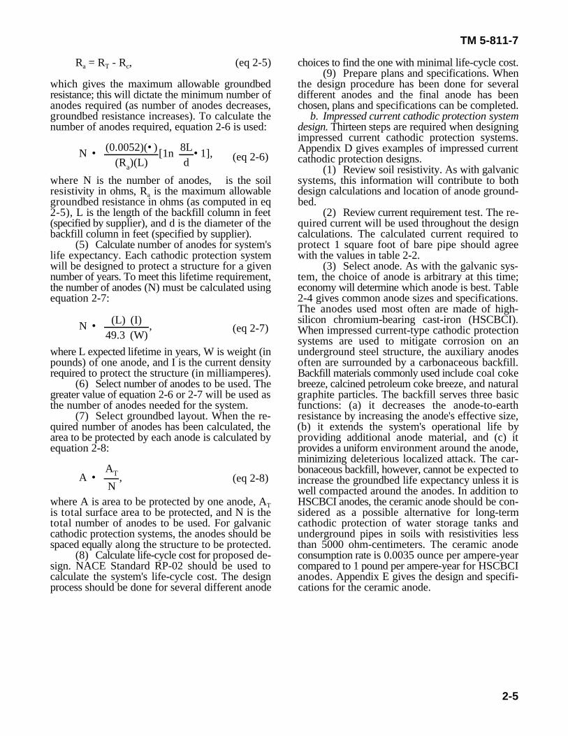
Table 2-4. Weights and dimensions of selected circular high- Table 2-5. Shape functions (K) for impressed current cathodicsilicon chromium-bearing cast iron anodes
Anode Anode Anode Packageweight dimensions surface area
(lb) (in.) size (in.) (sq ft)
12 1 x 60 1.4 10 x 8444 2 x 60 2.6 10 x 8460 2 x 60 2.8 10 x 84110 3 x 60 4.0 10 x 84
Reproduced from Harco Corporation, Catalog of Cathodic ProtectionMaterials, 1971. Used with permission.
(4) Calculate number of anodes needed tosatisfy manufactuere's current density limitations.Impressed current anodes are supplied with arecommended maximum current density. Highercurrent densities will reduce anode life. To deter-mine the number of anodes needed to meet thecurrent density limitations, use equation 2-9:
where N is number of anodes required, I is totalprotection current in milliamperes, A is anode sur-1face area in square feet per anode, and I is recom-1mended maximum current density output in milli-amperes.
(5) Calculate number of anodes needed tomeet design life requirement. Equation 2-10 is usedto find the number of anodes:
where N is number of anodes, L is life in years, andW is weight of one anode in pounds.
(6) Calculate number of anodes needed tomeet maximum anode groundbed resistance re-quirements. Equation 2-11 is used to calculate thenumber of anodes required:
where R is the anodes' resistance, • is soil resis-ativity in ohm-centimeters, K is the anode shapefactor from table 2-5, N is the number of anodes, Lis length of the anode backfill column in feet, P isthe paralleling factor from table 2-6, and S is thecenter-to-center spacing between anode backfillcolumns in feet.
protection anodes where L is effective anode lengthand d is anode/backfill diameter.
L/d K L/d K
5 0.0140 20 0.02136 0.0150 25 0.02247 0.0158 30 0.02348 0.0165 35 0.02429 0.0171 40 0.0249
10 0.0177 45 0.025512 0.0186 .50 0.026114 0.0194 55 0.026616 0.0201 60 0.027028 0.0207
Reproduced from W.T. Bryan, Designing Impressed CurrentCathodic Protection Systems With Durco Anodes, The DurironCompany, 1970. Used with permission.
Table 2-6. Anode paralleling factors (F) for various numbers ofanodes (N) installed in parallel
N P N P
2 0.00261 14 0.001683 0.00289 16 0.001554 0.00283 18 0.001455 0.00268 20 0.001356 0.00252 22 0.001287 0.00237 24 0.001218 0.00224 26 0.001149 0.00212 28 0.00109
10 0.00201 30 0.0010412 0.00182
Reproduced from W.T. Bryan, Designing Impressed CurrentCathodic Protection Systems With Durco Anodes, The DurironCompany, 1970. Used with permission.
(7) Select number of anodes to be used. Thehighest number calculated by equation 2-9,2-10, or2-11 will be the number of anodes used.
(8) Select area for placement of anode bed.The area with the lowest soil resistivity will bechosen to minimize anode-to-electrolyte resistance.
(9) Determine total circuit resistance. Thetotal circuit resistance will be used to calculate therectifier size needed.
(a) Calculate anode groundbedresistance. Use equation 2-11.
(b) Calculate groundbed header cableresistance. The cable is typically supplied with aspecified resistance in ohms per 100 feet. The wireresistance then is calculated from equation 2-12:
Rw • ohms (L)100 ft
,
T • (0.0876)(I 2)(R)(L)(P)E
• (0.15)(S)(L),
Rc • RN
,
RT • Ra • Rw • Rc,
Vrec • (I)(RT)(150%),
TM 5-811-7
2-7
(eq 2-12)
(eq 2-14)
(eq 2-15)
(eq 2-16)where L is the structure's length in feet. Economicsare important in choosing a cable, and may indeedbe the controlling factor. To determine the totalannual cable cost, Kelvin's Economic Law can beused as shown in equation 2-13. where I is total protection current in amperes, R is
(eq 2-13) rectifiers are available commercially; one that sat-
where T is total annual cost in dollars per year, I is equation 2-16 should be chosen. Besides the moretotal protection current in amperes, R is cable common rectifiers being marketed, a solar cathodicresistance in ohms per 1000 feet, L is cable length protection power supply (for d.c. power) may bein feet, P is cost of electrical energy in farads per considered for remote sites with no electricalkilowatt-hour, E is the rectifier efficiency expressed power. Three factors that should be consideredas percent, and S is the cable's initial cost in dollars when specifying a solar cathodic protection powerper foot. supply are:
(c) Calculate structure-to-electrolyte resist- power supply in dollars per watt of continuousance using equation 2-14: power.
where R is the structure-to-electrolyte resistance, solar cathodic protection power supply, mainly tocR is the coating resistance in ohms per square feet, keep the solar panels free of dirt deposits. Appen-and N is the coated pipe area in square feet. dix F discusses rectifier current interference.
(d) Calculate total circuit resistance. To (12) Calculate system cost. As with the gal-calculate the total resistance, R , equation 2-15 is vanic cathodic protection system, the choice ofTused: anode for design calculation is arbitrary. When
where variables are the same as for equations 2-11, (13) Prepare plans and specifications.242, and 2-14.
(10) Calculate rectifier voltage. Equation 2-16 is used to determine voltage output (V ) of therecrectifier:
Ttotal circuit resistance, and 150 percent is a factorto allow for aging of the rectifier stacks.
(11) Select a rectifier. A rectifier must bechosen based on the results of equation 2-16. Many
isfies the minimum requirements of (I) and (V ) inrec
—The cost of the solar cathodic protection
—The solar cathodic protection power sup-ply's much higher initial cost compared to seleniumrectifiers operated by a.c. power.
—The additional maintenance required for a
several anodes have been used in the design calcu-lations, an economic analysis should be done asrecommended in NACE Standard RP-02.
TM 5-811-7
A-1
APPENDIX ASOIL RESISTIVITY MEASUREMENT
A-1. Introduction.Since soil resistivity is a major factor affecting the corrosion rate, the design engineer should know how tomeasure it. Generally, as soil resistivity decreases, corrosivity increases. In addition, as soil moisture contentincreases, resistivity decreases. Soil resistivity typically is measured using one or both of two methods: (1)testing onsite with the Wenner four-pin method, and/or (2) taking a soil sample to a laboratory for a soil boxresistivity test. It must be stressed that soil resistivity may vary widely within very short distances. Soilresistivity also changes with depth below the ground surface. Thus, if the soil sample method is used, manysamples must be taken for an accurate map of soil resistivities in the area. The soil box resistivity test alsois much more time-consuming than the four-pin method.
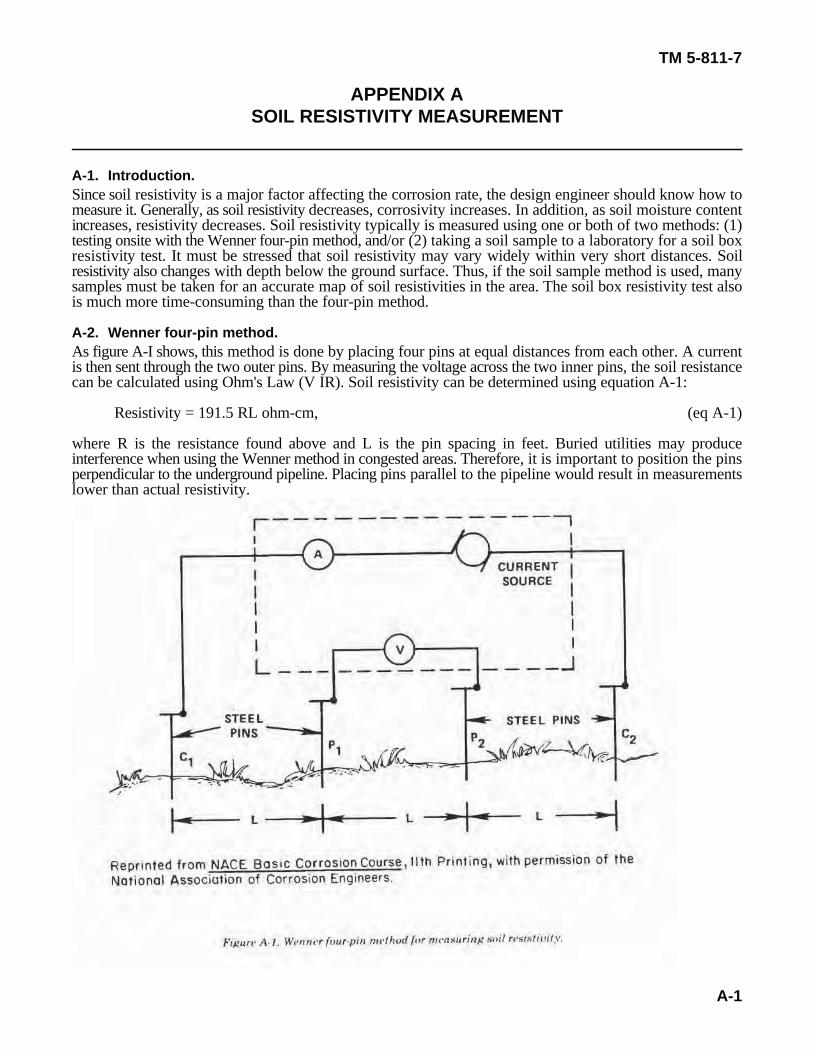
A-2. Wenner four-pin method.As figure A-I shows, this method is done by placing four pins at equal distances from each other. A currentis then sent through the two outer pins. By measuring the voltage across the two inner pins, the soil resistancecan be calculated using Ohm's Law (V IR). Soil resistivity can be determined using equation A-1:
Resistivity = 191.5 RL ohm-cm, (eq A-1)
where R is the resistance found above and L is the pin spacing in feet. Buried utilities may produceinterference when using the Wenner method in congested areas. Therefore, it is important to position the pinsperpendicular to the underground pipeline. Placing pins parallel to the pipeline would result in measurementslower than actual resistivity.
Resistivity • R WDL
,
TM 5-811-7
A-2
(eq A-2)
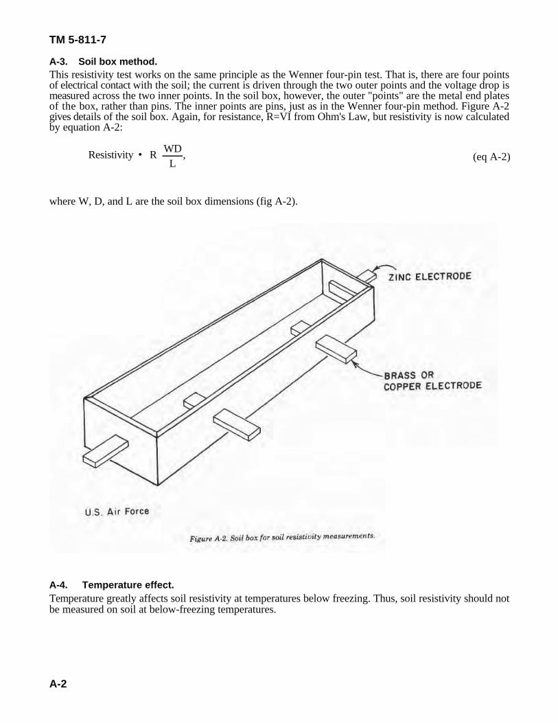
A-3. Soil box method.This resistivity test works on the same principle as the Wenner four-pin test. That is, there are four pointsof electrical contact with the soil; the current is driven through the two outer points and the voltage drop ismeasured across the two inner points. In the soil box, however, the outer "points" are the metal end platesof the box, rather than pins. The inner points are pins, just as in the Wenner four-pin method. Figure A-2gives details of the soil box. Again, for resistance, R=VI from Ohm's Law, but resistivity is now calculatedby equation A-2:
where W, D, and L are the soil box dimensions (fig A-2).
A-4. Temperature effect.Temperature greatly affects soil resistivity at temperatures below freezing. Thus, soil resistivity should notbe measured on soil at below-freezing temperatures.
TM 5-811-7
B-1
APPENDIX BCURRENT REQUIREMENT TESTING
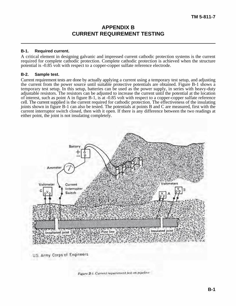
B-1. Required current.A critical element in designing galvanic and impressed current cathodic protection systems is the currentrequired for complete cathodic protection. Complete cathodic protection is achieved when the structurepotential is -0.85 volt with respect to a copper-copper sulfate reference electrode.
B-2. Sample test.Current requirement tests are done by actually applying a current using a temporary test setup, and adjustingthe current from the power source until suitable protective potentials are obtained. Figure B-1 shows atemporary test setup. In this setup, batteries can be used as the power supply, in series with heavy-dutyadjustable resistors. The resistors can be adjusted to increase the current until the potential at the locationof interest, such as point A in figure B-1, is at -0.85 volt with respect to a copper-copper sulfate referencecell. The current supplied is the current required for cathodic protection. The effectiveness of the insulatingjoints shown in figure B-1 can also be tested. The potentials at points B and C are measured, first with thecurrent interruptor switch closed, then with it open. If there is any difference between the two readings ateither point, the joint is not insulating completely.

TM 5-811-7
C-1
APPENDIX CEXAMPLES OF GALVANIC CATHODIC PROTECTION DESIGN
C-1. Purpose.The examples that follow show how to use the design procedure explained in paragraphs 2-1 and 2-2.
C-2. Aircraft multiple hydrant refueling system.Galvanic cathodic protection is designed for a standard aircraft hydrant refueling system as shown in figureC-1. This design is for a system not yet installed.
RT • • EI
,
RT • 0.90.726
× 1.23 ohms.
Rc • RN
TM 5-811-7
C-2
a. Design data.(1) Average soil resistivity is 5000 ohm-centimeters.(2) Effective coating resistance at 25 years will be 2500 ohms per square foot, as suggested by the
manufacturer.(3) Design for 90 percent coating efficiency, based on experience.(4) Design for 25-year life.(5) Design for 1 milliampere per square foot of bare pipe after polarization (corrosion history of area
indicates this value is adequate).(6) Magnesium packaged-type anodes must be used (soil resistivity is greater than 2000 ohm-
centimeters).(7) System is insulated well enough from foreign structures.(8) All piping is mill-coated with hot-applied coal-tar enamel and wrapped with asbestos felt. Coating
has been tested over the trench for holidays and defects have been corrected. Coating is assumed better than99.5 percent perfect at installation.
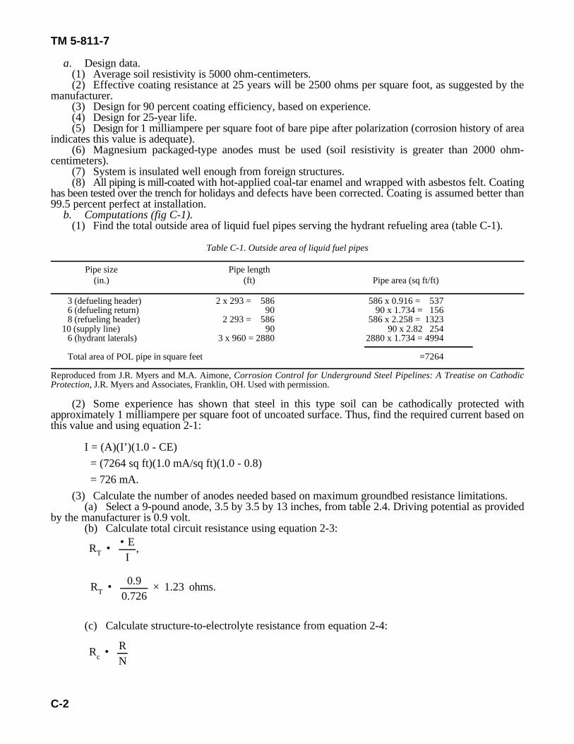
b. Computations (fig C-1).(1) Find the total outside area of liquid fuel pipes serving the hydrant refueling area (table C-1).
Table C-1. Outside area of liquid fuel pipes
Pipe size Pipe length(in.) (ft) Pipe area (sq ft/ft)
3 (defueling header) 2 x 293 = 586 586 x 0.916 = 5376 (defueling return) 90 90 x 1.734 = 1568 (refueling header) 2 293 = 586 586 x 2.258 = 1323
10 (supply line) 90 90 x 2.82 2546 (hydrant laterals) 3 x 960 = 2880 2880 x 1.734 = 4994
Total area of POL pipe in square feet =7264
Reproduced from J.R. Myers and M.A. Aimone, Corrosion Control for Underground Steel Pipelines: A Treatise on CathodicProtection, J.R. Myers and Associates, Franklin, OH. Used with permission.
(2) Some experience has shown that steel in this type soil can be cathodically protected withapproximately 1 milliampere per square foot of uncoated surface. Thus, find the required current based onthis value and using equation 2-1:
I = (A)(I’)(1.0 - CE) = (7264 sq ft)(1.0 mA/sq ft)(1.0 - 0.8) = 726 mA.
(3) Calculate the number of anodes needed based on maximum groundbed resistance limitations.(a) Select a 9-pound anode, 3.5 by 3.5 by 13 inches, from table 2.4. Driving potential as provided
by the manufacturer is 0.9 volt.(b) Calculate total circuit resistance using equation 2-3:
(c) Calculate structure-to-electrolyte resistance from equation 2-4:
Rc • 2500 ohms/sq ft7264 sq ft
Rc • 0.345 ohm.
RT • Ra • Rw • Rc
N • (0.0052)(• )(Ra)(L)
[1n 8Ld
• 1],
N • (0.0052)(500 ohm• cm)(0.89 ohm)(1.42 ft)
[1n (8)(1.42 ft)(0.5 ft)
• 1]
N • (L)(I)49.3 (W)
,
N • (25 yr)(726 mA)49.3 (9 lb/anode)
,
A •AT
N
A • 7264 sq ft44 anodes
TM 5-811-7
C-3
(d) Find maximum allowable groundbed resistance using equation 2-2:
1.23 ohm = R + 0.345 ohm (assume R is negligible)a w
0.89 ohm = Ra
(e) Calculate number of anodes from equation 2-6:
(values for Land D fromsupplier.)
N = 44 anodes.(4) Calculate number of anodes based on system’s life expectancy and using equation 2-7:
N = 41 anodes.(5) Select number of anodes. Since 44 anodes are required to meet maximum allowable groundbed
resistance (e above), that will be the number used.(6) Select groundbed layout. Determine the area to be covered by each anode using equation 2-8:
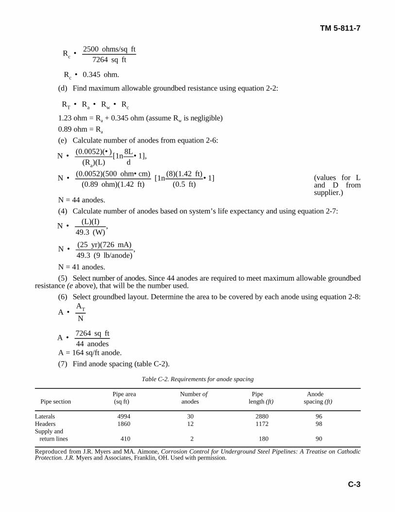
A = 164 sq/ft anode.(7) Find anode spacing (table C-2).
Table C-2. Requirements for anode spacing
Pipe area Number of Pipe AnodePipe section (sq ft) anodes length (ft) spacing (ft)
Laterals 4994 30 2880 96Headers 1860 12 1172 98Supply and return lines 410 2 180 90
Reproduced from J.R. Myers and MA. Aimone, Corrosion Control for Underground Steel Pipelines: A Treatise on CathodicProtection. J.R. Myers and Associates, Franklin, OH. Used with permission.
TM 5-811-7
C-4
(8) Calculate life-cycle cost as recommended in paragraph 2-2. Comparisons with other anode sizesand types will yield the most economical design.
c. Placement. Locate anodes as shown in figure C-1.
C-3. Alternative calculations.The design examples in paragraphs C-4 and C-5 below use calculations that differ from those used in the textand in paragraph C-2. Exposure to different methods of calculation should help the design engineer to betterunderstand the design procedure.
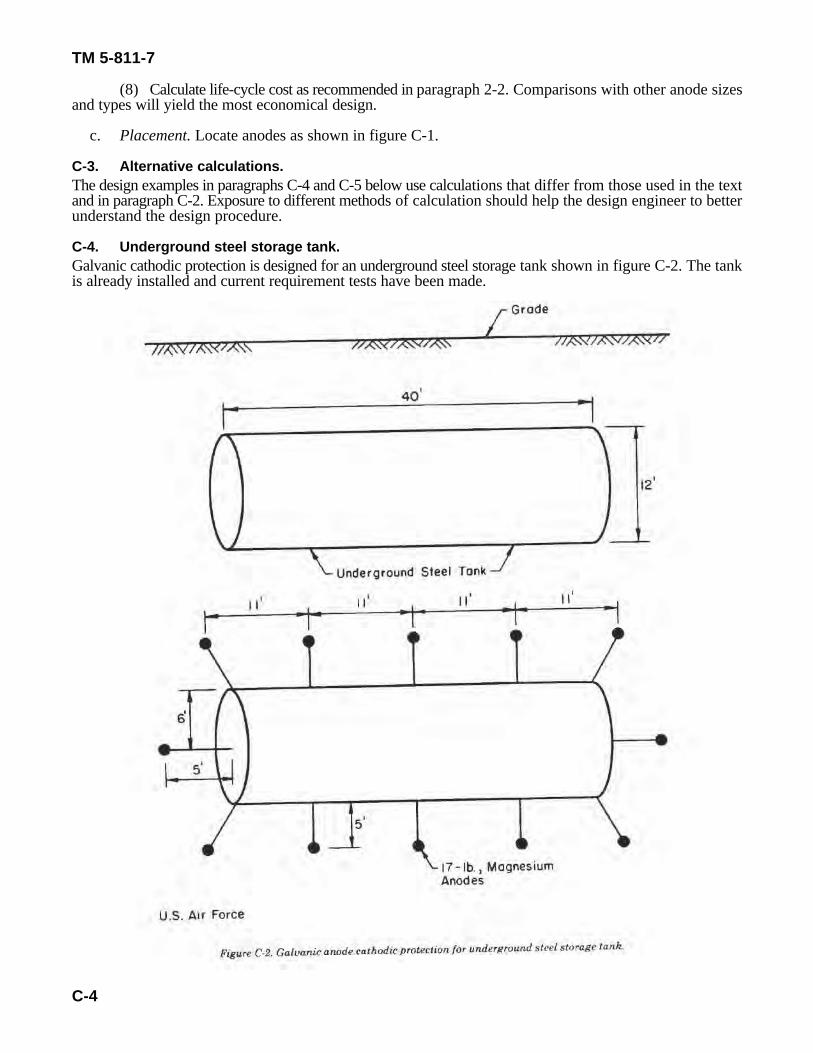
C-4. Underground steel storage tank.Galvanic cathodic protection is designed for an underground steel storage tank shown in figure C-2. The tankis already installed and current requirement tests have been made.
W • YSIE
,
W • (15 yr)(8.8 lb/A• yr)(0.7 A)0.50
,
N • 184.817
• 10.9 (use 12 anodes for symmetry).
TM 5-811-7
C-5
(eq C-1)
a. Design data.(1) Tank diameter is 12 feet.(2) Tank length is 40 feet.(3) Design for 80 percent coating efficiency, based on experience.(4) Design for 15-year life.(5) Current requirement is 0.7 ampere.(6) Packaged 17-pound standard magnesium anodes must be used.(7) The tank is insulated well enough from foreign structures.
b. Computations.(1) Find the minimum weight of anodes required for the tank using equation C-I:
where Y = 15 years, S = 8.8 pounds per ampere-year, I = 0.7 ampere, and E = 0.50 efficiency. Thus,
W= 184.8 lb.
(2) Find the number of magnesium anodes (17 pounds each) required:
c. Placement. Locate anodes as shown in figure C-2.
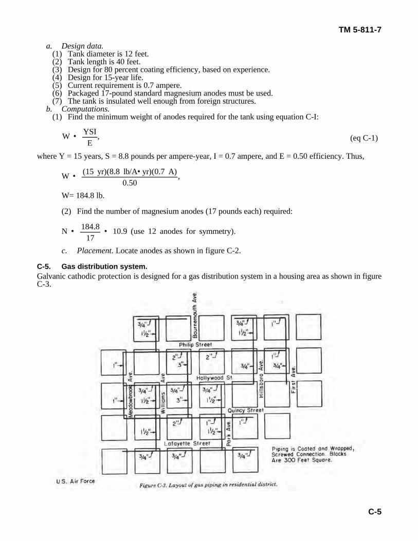
C-5. Gas distribution system.Galvanic cathodic protection is designed for a gas distribution system in a housing area as shown in figureC-3.
W • YSIE
,
W • (15 yr)(8.8 lb/A• yr)(0.858 A)0.50
,
TM 5-811-7
C-6
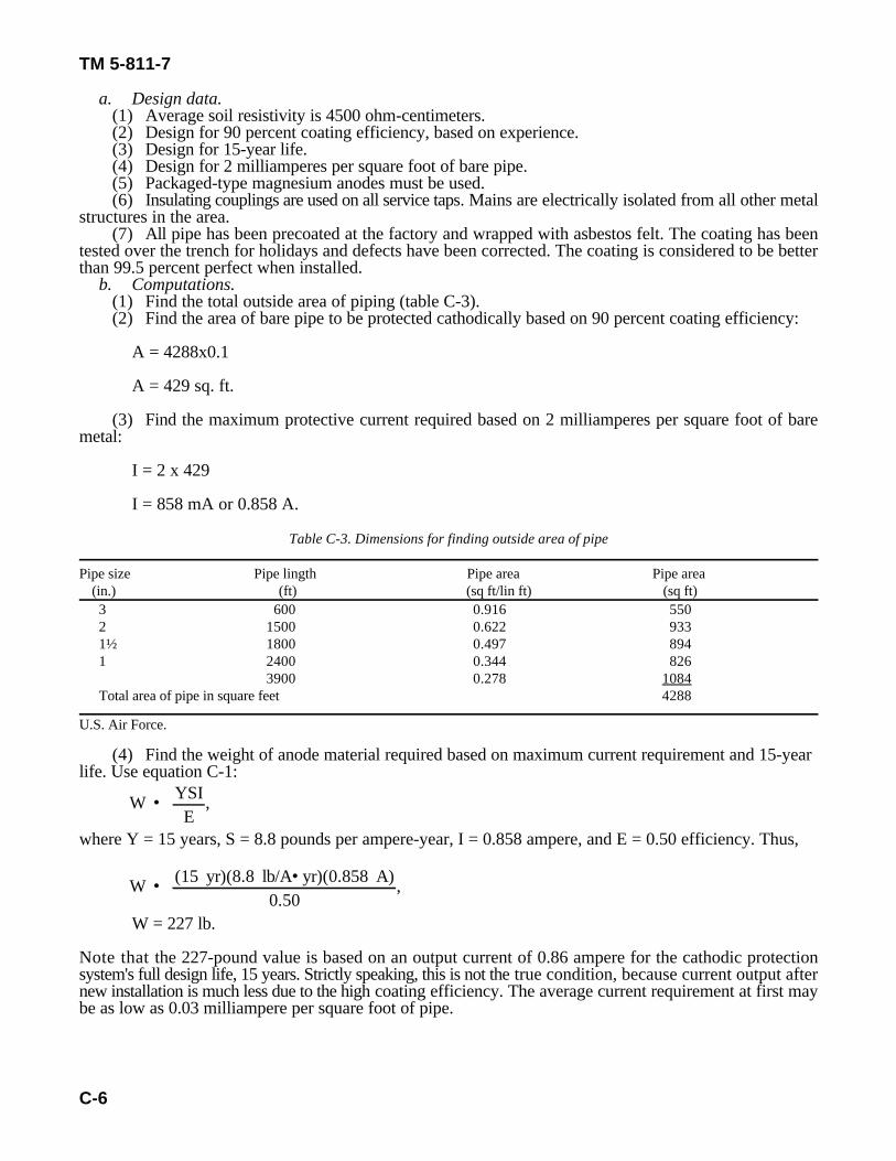
a. Design data.(1) Average soil resistivity is 4500 ohm-centimeters.(2) Design for 90 percent coating efficiency, based on experience.(3) Design for 15-year life.(4) Design for 2 milliamperes per square foot of bare pipe.(5) Packaged-type magnesium anodes must be used.(6) Insulating couplings are used on all service taps. Mains are electrically isolated from all other metal
structures in the area.(7) All pipe has been precoated at the factory and wrapped with asbestos felt. The coating has been
tested over the trench for holidays and defects have been corrected. The coating is considered to be betterthan 99.5 percent perfect when installed.
b. Computations.(1) Find the total outside area of piping (table C-3).(2) Find the area of bare pipe to be protected cathodically based on 90 percent coating efficiency:
A = 4288x0.1
A = 429 sq. ft.
(3) Find the maximum protective current required based on 2 milliamperes per square foot of baremetal:
I = 2 x 429
I = 858 mA or 0.858 A.
Table C-3. Dimensions for finding outside area of pipe
Pipe size Pipe lingth Pipe area Pipe area(in.) (ft) (sq ft/lin ft) (sq ft)3 600 0.916 5502 1500 0.622 9331½ 1800 0.497 8941 2400 0.344 826
3900 0.278 1084Total area of pipe in square feet 4288
U.S. Air Force.
(4) Find the weight of anode material required based on maximum current requirement and 15-yearlife. Use equation C-1:
where Y = 15 years, S = 8.8 pounds per ampere-year, I = 0.858 ampere, and E = 0.50 efficiency. Thus,
W = 227 lb.
Note that the 227-pound value is based on an output current of 0.86 ampere for the cathodic protectionsystem's full design life, 15 years. Strictly speaking, this is not the true condition, because current output afternew installation is much less due to the high coating efficiency. The average current requirement at first maybe as low as 0.03 milliampere per square foot of pipe.
i • CfyP
,
i • 120,000 × 1.00 × 1.004500 ohm• cm
TM 5-811-7
C-7
(eq C-2)
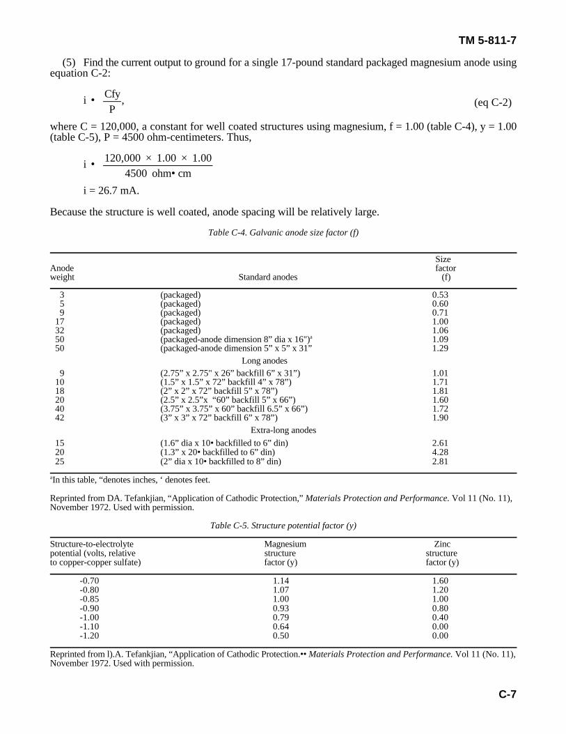
(5) Find the current output to ground for a single 17-pound standard packaged magnesium anode usingequation C-2:
where C = 120,000, a constant for well coated structures using magnesium, f = 1.00 (table C-4), y = 1.00(table C-5), P = 4500 ohm-centimeters. Thus,
i = 26.7 mA.
Because the structure is well coated, anode spacing will be relatively large.
Table C-4. Galvanic anode size factor (f)
SizeAnode factorweight Standard anodes (f)
3 (packaged) 0.535 (packaged) 0.609 (packaged) 0.71
17 (packaged) 1.0032 (packaged) 1.0650 (packaged-anode dimension 8” dia x 16") 1.09a
50 (packaged-anode dimension 5” x 5” x 31” 1.29Long anodes
9 (2.75” x 2.75" x 26” backfill 6” x 31”) 1.0110 (1.5” x 1.5” x 72” backfill 4” x 78”) 1.7118 (2” x 2” x 72” backfill 5” x 78”) 1.8120 (2.5” x 2.5”x “60” backfill 5” x 66”) 1.6040 (3.75” x 3.75” x 60” backfill 6.5” x 66”) 1.7242 (3” x 3” x 72” backfill 6” x 78”) 1.90
Extra-long anodes15 (1.6” dia x 10• backfilled to 6” din) 2.6120 (1.3” x 20• backfilled to 6” din) 4.2825 (2” dia x 10• backfilled to 8” din) 2.81
In this table, “denotes inches, ‘ denotes feet.a
Reprinted from DA. Tefankjian, “Application of Cathodic Protection,” Materials Protection and Performance. Vol 11 (No. 11),November 1972. Used with permission.
Table C-5. Structure potential factor (y)
Structure-to-electrolyte Magnesium Zincpotential (volts, relative structure structureto copper-copper sulfate) factor (y) factor (y)
-0.70 1.14 1.60-0.80 1.07 1.20-0.85 1.00 1.00-0.90 0.93 0.80-1.00 0.79 0.40-1.10 0.64 0.00-1.20 0.50 0.00
Reprinted from l).A. Tefankjian, “Application of Cathodic Protection.•• Materials Protection and Performance. Vol 11 (No. 11),November 1972. Used with permission.
n • Ii,
n • 85826.7
TM 5-811-7
C-8
(eq C-3)
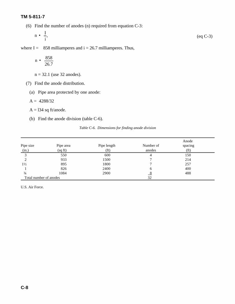
(6) Find the number of anodes (n) required from equation C-3:
where I = 858 milliamperes and i = 26.7 milliamperes. Thus,
n = 32.1 (use 32 anodes).
(7) Find the anode distribution.
(a) Pipe area protected by one anode:
A = 4288/32
A = l34 sq ft/anode.
(b) Find the anode division (table C-6).
Table C-6. Dimensions for finding anode division
AnodePipe size Pipe area Pipe length Number of spacing(in.) (sq ft) (ft) anodes (ft)
3 550 600 4 1502 933 1500 7 214
1½ 895 1800 7 2571 826 2400 6 400¾ 1084 2900 8 488Total number of anodes 32
U.S. Air Force.
TM 5-811-7
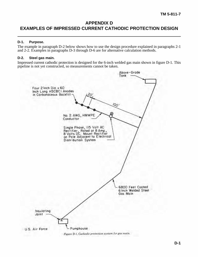
D-1
APPENDIX DEXAMPLES OF IMPRESSED CURRENT CATHODIC PROTECTION DESIGN
D-1. Purpose.The example in paragraph D-2 below shows how to use the design procedure explained in paragraphs 2-1and 2-2. Examples in paragraphs D-3 through D-6 are for alternative calculation methods.
D-2. Steel gas main.Impressed current cathodic protection is designed for the 6-inch welded gas main shown in figure D-1. Thispipeline is not yet constructed, so measurements cannot be taken.
N • I(A1)(I1)
N • 2360 mA(28 sq ft/anode)(1000 mA/sq ft)
,
N • (L)(I)(1000)(W)
N • (15 years)(2360mA)(1000)(60 lb/anode)
• 0.59 anode
TM 5-811-7
D-2
a. Design data.
(1) Average soil resistivity is 2000 ohm-centimeters.(2) Effective coating resistance at 15 years is estimated at 2500 ohms per square foot.(3) Pipe has a 6-inch outside diameter.(4) Pipe length is 6800 feet.(5) Design for 15-year life.(6) Design for 2 milliamperes per square foot of bare pipe.(7) Design for 90 percent coating efficiency based on experience.(8) The pipeline must be isolated from the pumphouse with an insulating joint on the main line inside
the pumphouse.(9) HSCBCI anodes must be used with carbonaceous backfill.(10) The pipe will be coated with hot-applied coal-tar enamel and will be holiday-checked before
installation.(11) Anode bed must not exceed 2 ohms.(12) Electric power is available at 120/240 volts a.c. single phase from a nearby overhead distribution
system.(13) Current requirement test indicates that 2.36 amperes are needed for adequate cathodic
protection.b. Computations.
(1) Find the gas main’s outside area:Pipe size - 6 in.Pipe length - 6800 ftPipe area - 6800 x • A = L • d = 6800 • 6 = 10,681 sq ft.
2 12
(2) Check the current requirement using equation 2-1:
I = (A)(I’)(1.0 - CE)
I = 10681 sq ft (2 mA/sq ft)(1.0 - 0.9)
I = 2136 mA,
which agrees with the current requirement test in 13 above.(3) Select an anode. From table 2-4, choose the 60-pound anode with a 2.8-square-foot surface area
(arbitrary selection).(4) Calculate the number of anodes needed to meet the anode supplier’s current density limitations; use
equation 2-9:
(Recommended maximumcurrent density output forhigh-silicon chromium-bearing cast-iron anodes is1000 mA/sq ft.)
N = 0.84 anode
(5) Calculate the number of anodes required to meet the design life requirements from equation 2-10:
Ra • (• K)LN
• • PS
N • • K
L (Ra • •S
P
N • 2000 ohm• cm (0.016S)
7 ft (20 ohm • (2000 ohm/cm (0.20 ft
Ra • (• K)LN
• • PS
Ra • 2000 ohm• cm (0.0165)(4 anodes)(7 ft)
• (2000
Rc • RN
Rc • 2500 ohm/sq ft11,800 sq ft
TM 5-811-7
D-3
(6) Calculate the number of anodes required to meet maximum anode groundbed resistancerequirements from equation 2-11:
(Values for K and Pfrom tables 2-6 and2-7, respectively.)
N = 2.75 • 3 anodes.
(7) Select the number of anodes to be used. Since the last calculation resulted in the largest number ofanodes, it will be used. The groundbed resistance, Ra, using three anodes, would equal 1.86 ohms; to insurecompliance with the manufacturer's limitations, four anodes will be used.
(8) Select an area for anode bed placement. The area of lowest resistivity will be used, which is 100feet from the pipeline.
(9) Determine the total circuit resistance.
(a) Calculate the anode groundbed resistance using equation 2-11:
(Values for K and Pare from tables 2-6 and2-7, respectively.)
R = 1.46 ohm.a
(b) Calculate the groundbed resistance for a 50-foot header cable using equation 2-12. The resistancespecified by the manufacturer is 0.0159 ohm per 100 ft of No.2 AWG cable:
R = (ohms/ft)(L)w
R = (0.0159 ohm/100 ft)(500 ft) = 0.0795 ohm.w
(c) Calculate the structure-to-electrolyte resistance from equation 2-14:
= 0.212 ohm
TM 5-811-7
D-4
(d) Calculate the total resistance (eq 2-15):
R = R + R + RT a w c
R = 1.46 ohm + 0.0795 ohm + 0.212 ohmT
R = 1.75 ohms.T
(10) Calculate the rectifier voltage from equation 2-16:
v( ) = (I)(R )(150%)rec T
v( ) = (2.36 A)(1.75 ohms)(150%)rec
v( ) = 6.2 V.rec
c. Select rectifier. Based on the design requirement of 6.2 volts and 2.36 amperes, a rectifier can bechosen from those marketed. After a rectifier has been chosen, the system's cost can be calculated inaccordance with paragraph 2-2. A comparison with other anode sizes and types will yield the mosteconomical design.
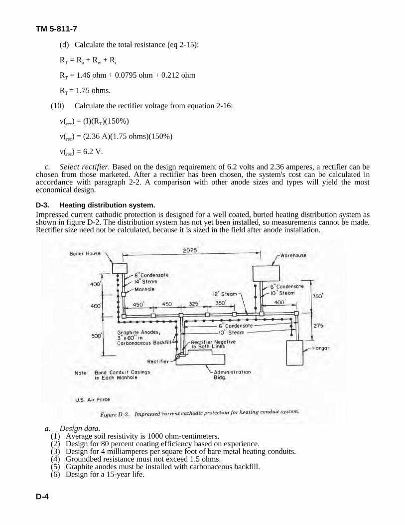
D-3. Heating distribution system.Impressed current cathodic protection is designed for a well coated, buried heating distribution system asshown in figure D-2. The distribution system has not yet been installed, so measurements cannot be made.Rectifier size need not be calculated, because it is sized in the field after anode installation.
a. Design data.(1) Average soil resistivity is 1000 ohm-centimeters.(2) Design for 80 percent coating efficiency based on experience.(3) Design for 4 milliamperes per square foot of bare metal heating conduits.(4) Groundbed resistance must not exceed 1.5 ohms.(5) Graphite anodes must be installed with carbonaceous backfill.(6) Design for a 15-year life.
TM 5-811-7
D-5
(7) Insulating joints must be provided on both steam and condensate lines at the first flange connectioninside all buildings.
(8) All conduit must be metal-bonded together in each manhole.(9) All conduit will be precoated at the factory and will not have been holiday-checked.(10) Single-phase electrical power is available at 120/240 volts a.c. from the administration building.
b. Computations.(1) Find the conduit's total outside area. Because the gage of the metal from which the conduit is made
ranges between 14 and 16, the pipe's outside diameter is considered the same as the inside diameter.(a) Steam conduit area must be calculated (table D-1).
Table D-1. Dimensions for finding steam conduit area: heat distribution system
Conduit area ConduitConduit size Conduit length (sq ft/ area
(in.) (ft) (lin ft) (sq ft)
14 1700 3.67 623912 1125 3.14 353310 1525 2.62 3996Total area of steam conduit 13,768
U.S. Air Force
(b) Condensate return conduit area must be calculated (table D-2).
Table D-2. Dimensions for finding condensate return conduit area: heat distribution system
Conduit area ConduitConduit size Conduit length (sq ft/ area
(in.) (ft) (lin ft) (sq ft)
8 1700 2.09 35536 2650 1.57 4161
Total area of condensate return conduit 7713Total outside area of all conduit 21481
U.S. Air Force.
(2) Find the area of bare pipe to be cathodically protected based on 80 percent coating efficiency:
A=21,481 x 0.2
A = 4296 sq ft.
(3) Find the maximum protective current required based on 4 milliamperes per square foot of baremetal:
I = 4296 x 4
I = 17,184 mA or 17.2 A.
(4) Compute the maximum weight of anode material needed for 15 years' life.(a) Graphite anodes are used.(b) Average deterioration rate for graphite is 2.0 pounds per ampere-year.
W • YSIE
,
W • (15 yr)(2.0 lb/A• yr)(17.2A)0.50
,
Rv • PKL
,
Rv • (1000 ohm• cm)(0.0167)7.0 feet
,
TM 5-811-7
D-6
(eq D-1)
(c) Find the maximum weight of anode material required (use eq C-1 from appendix C):
where Y = 15 years, S = 2.0 pounds per ampere-year, I = 17.2 amperes, and E = 0.50 efficiency. Thus,
W = 1032 lb.
c. Groundbed design.(1) Anode size is 3-inch by 60-inch (backfilled 10-inch by 84-inch) and weight is 25 pounds per anode
unit.(2) Find the resistance to earth of a single anode:
where P = 1000 ohm-centimeters, L = 7.0 feet (backfilled size), and K = 0.0167, L/d = 8.4 (table 2-6). Thus,
R = 2.39 ohmsv
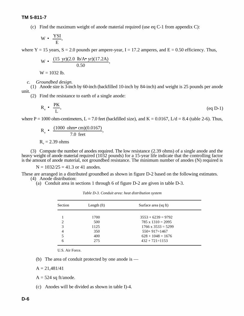
(3) Compute the number of anodes required. The low resistance (2.39 ohms) of a single anode and theheavy weight of anode material required (1032 pounds) for a 15-year life indicate that the controlling factoris the amount of anode material, not groundbed resistance. The minimum number of anodes (N) required is
N = 1032/25 = 41.3 or 41 anodes.These are arranged in a distributed groundbed as shown in figure D-2 based on the following estimates.
(4) Anode distribution:(a) Conduit area in sections 1 through 6 of figure D-2 are given in table D-3.
Table D-3. Conduit area: heat distribution system
Section Length (ft) Surface area (sq ft)
1 1700 3553 + 6239 = 97922 500 785 x 1310 = 20953 1125 1766 x 3533 = 52994 350 550+ 917=14675 400 628 + 1048 = 16766 275 432 + 721=1153
U.S. Air Force.
(b) The area of conduit protected by one anode is —
A = 21,481/41
A = 524 sq ft/anode.
(c) Anodes will be divided as shown in table I)-4.
TM 5-811-7
D-7
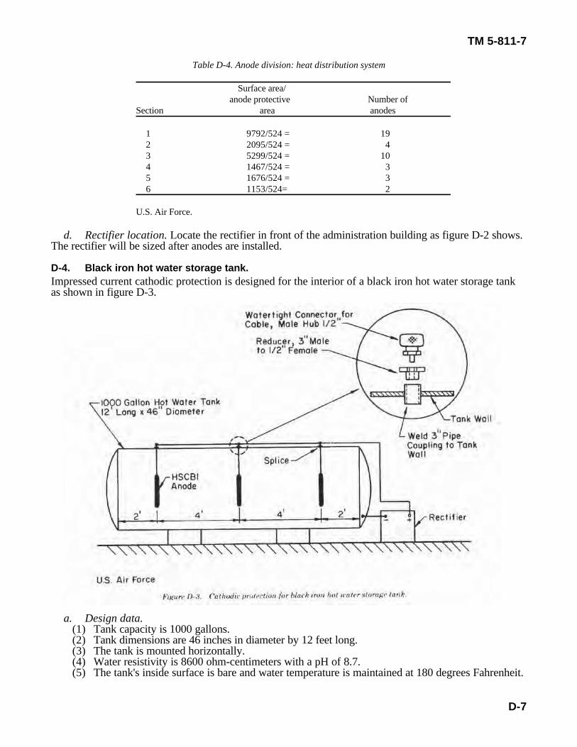
Table D-4. Anode division: heat distribution system
Surface area/anode protective Number of
Section area anodes
1 9792/524 = 192 2095/524 = 43 5299/524 = 104 1467/524 = 35 1676/524 = 36 1153/524= 2
U.S. Air Force.
d. Rectifier location. Locate the rectifier in front of the administration building as figure D-2 shows.The rectifier will be sized after anodes are installed.
D-4. Black iron hot water storage tank.Impressed current cathodic protection is designed for the interior of a black iron hot water storage tankas shown in figure D-3.
a. Design data.(1) Tank capacity is 1000 gallons.(2) Tank dimensions are 46 inches in diameter by 12 feet long.(3) The tank is mounted horizontally.(4) Water resistivity is 8600 ohm-centimeters with a pH of 8.7.(5) The tank's inside surface is bare and water temperature is maintained at 180 degrees Fahrenheit.
W • YSIE
,
W • (5 yr)(1.0 lb/A• yr)(0.84 A)0.50
R • 0.012P log (d/D)L
R • 0.012 × (8600 ohm• cm) log (3.83 ft/0.125 ft)0.75 ft
R • 103.2 × log 30.640.75
TM 5-811-7
D-8
(eq D-3)
(6) Design for a maximum current density of 5 milliamperes per square foot.(7) Design for a 5-year life.(8) Use HSCBCI anodes.(9) Electrical current is available at 115 volts a.c., single phase.
b. Computations.(1) Find the tank's interior area using equation D-2:
A = 2 r + dL,T2
where r=1.92 feet, d=3.83 feet, and L = 12 feet. Thus,
A = 2 x 3.1416 x (1.92) + 3.1416 x 3.38 x 12T2
A = 167.5 sq ft.T
(2) Find the maximum protective current required:
I = 167.5 x 5
I = 838 mA or 0.84 A.
(3) Find the minimum weight of anode material needed for a 5-year life (eq C-I from appendix C):
where Y = 5 years, S = 1.0 pound per ampere-year, I = 0.84 ampere, and E = 0.50. Thus,
W = 8.4 lb.
(4) Compute the number of anodes required. An anode 1½ inches in diameter by 9 inches long weighing4 pounds is chosen as the most suitable size. For proper current distribution, three anodes are required.
(5) Find the resistance of a single anode using equation D-3:
where P =8600 ohm-centimeters, D = 3.83 feet (tank diameter), d = 1½ inches or 0.125 foot (anodediameter), L = 9 inches or 0.75 foot (anode length). Thus,
R = 204.5 ohms
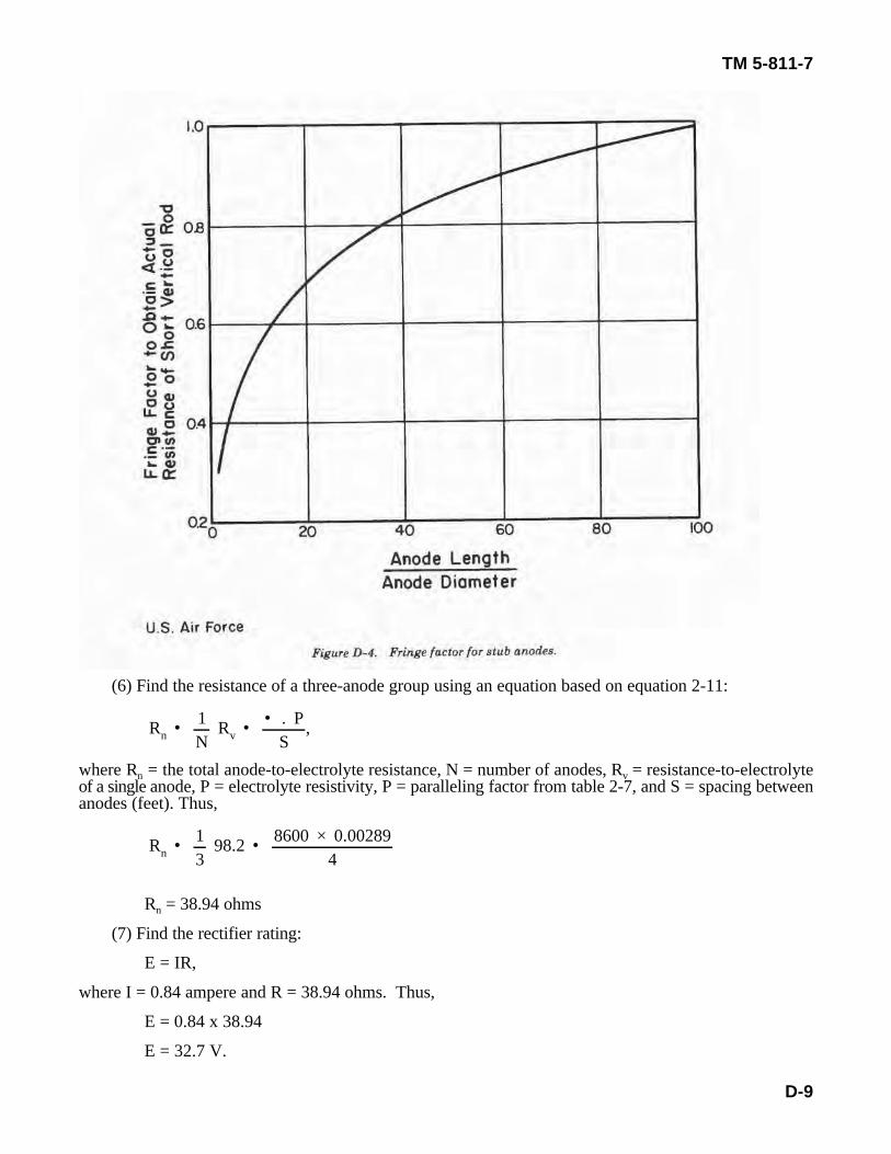
This resistance must be corrected by the fringe factor because the anodes are short. The fringe factor is 0.48from the curve in figure D-4 for an L/d = 9/1.5 = 6:
R = 204.5 x 0.48
R = 98.2 ohms.
Rn • 1N
Rv • • . PS
,
Rn • 13
98.2 • 8600 × 0.002894
TM 5-811-7
D-9
(6) Find the resistance of a three-anode group using an equation based on equation 2-11:
where R = the total anode-to-electrolyte resistance, N = number of anodes, R = resistance-to-electrolyten vof a single anode, P = electrolyte resistivity, P = paralleling factor from table 2-7, and S = spacing betweenanodes (feet). Thus,
R = 38.94 ohmsn
(7) Find the rectifier rating:
E = IR,
where I = 0.84 ampere and R = 38.94 ohms. Thus,
E = 0.84 x 38.94
E = 32.7 V.
TM 5-811-7
D-10
(a) To allow rectifier aging and film formation, it is considered good practice to use 1.5 as amultiplying factor:
E = 1.5 x 32.7 = 49.1 V.
(b) The rectifier chosen should produce a d.c. voltage that meets the size requirements of 60-volt,4-ampere, single-phase.
(8) Locate the rectifier adjacent to tank for the following reasons:(a) Usually cheaper to install.(b) Easier to maintain.(c) Keeps d.c. voltage drop to a minimum.
(9) The d.c. circuit conductors should be installed as follows:(a) Outside tank — use No.2 AWG high molecular weight polyethylene extruded (HMWPE)
conductor.(b) Inside tank — use No.8 AWG HMWPE conductor.
(10) The cable should not be stressed or bent.
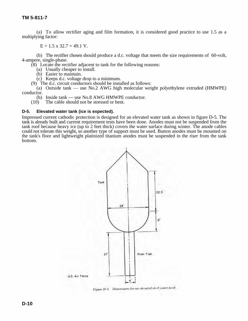
D-5. Elevated water tank (ice is expected).Impressed current cathodic protection is designed for an elevated water tank as shown in figure D-5. Thetank is already built and current requirement tests have been done. Anodes must not be suspended from thetank roof because heavy ice (up to 2 feet thick) covers the water surface during winter. The anode cablescould not tolerate this weight, so another type of support must be used. Button anodes must be mounted onthe tank's floor and lightweight platinized titanium anodes must be suspended in the riser from the tankbottom.
W • YSIE
,
W • (15 yr)(1.0 lb/A• yr)(7.0 A)0.50
,
N • 21055
• 3.82 (use 4 anodes).
W • YSIE
,
W • (15 yr)(1.32 × 10• 5lb/A• yr)(1.0 A0.50
N • 3.96 × 10• 4
8.8 × 10• 5• 4.5 (use 5 anodes).
TM 5-811-7
D-11
a. Design data.(1) Tank height (from ground to bottom of bowl) is 37 feet.(2) Tank diameter is 24 feet.(3) High water level in the tank is 34.5 feet.(4) Overall tank depth is 34.5 feet.(5) Vertical shell height is 22.5 feet.(6) Riser pipe diameter is 4 feet.(7) The tank has a semicircular bottom.(8) All inner surfaces are uncoated.(9) Current required for protection — bowl, 7.0 amperes, rise, 1.0 ampere.(10) Electrical power available is 120/240-volt a.c., single phase.(11) Tank is subject to freezing.(12) Design for a 15-year life.(13) Water resistivity is 4000 ohm-centimeters.(14) Button-type HSCBCI anodes are used for the tank.(15) Riser anodes are platinized titanium wire.
b. Computations.(1) Find the minimum weight of button anode material required for the tank (eq C-1 from appendix C):
where Y = 15 years, S = 1.0 pound per ampere-year, I = 7.0 amperes, and E = 0.50. Thus,
W = 210 lb.
(2) Compute the number of tank anodes needed (button anodes weigh 55 pounds):
(3) Find the minimum weight of riser anode material required for the riser (eq C-I from appendix C):
where Y = 15 years, S = 1.32 x 10 pound per ampere-year, I = 1.0 ampere, and 0 = 0.50. Thus,-5
W = 3.96 x 10 lb.-4
(4) Find the number of riser anodes needed. Platinized titanium wire, 0.1-inch in diameter, 3 feet long,with .001-inch-think platinum over titanium will be used for each anode. The weight of platinum on eachanode is 8.8 x 10 pound. Thus,-5
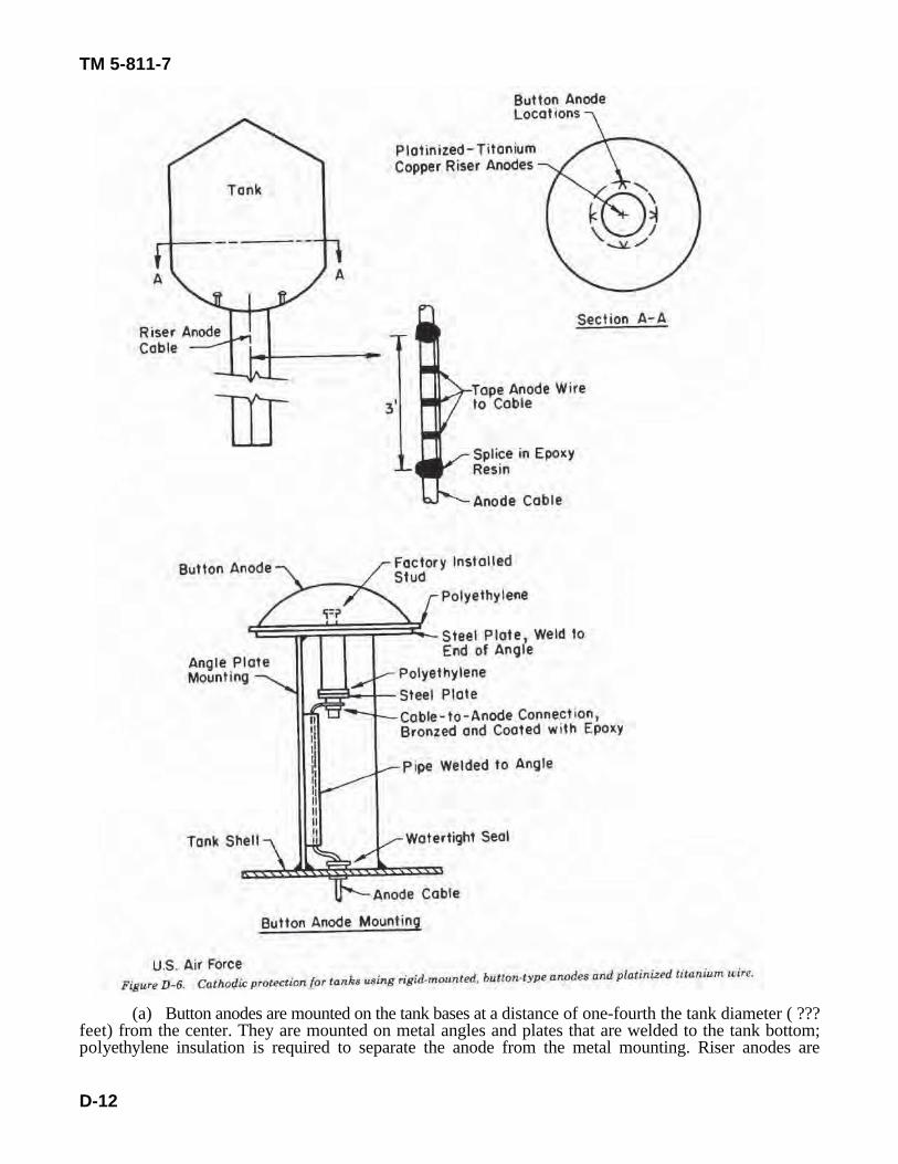
(5) locate anodes as shown in figure D-6.
TM 5-811-7
D-12
(a) Button anodes are mounted on the tank bases at a distance of one-fourth the tank diameter ( ???feet) from the center. They are mounted on metal angles and plates that are welded to the tank bottom;polyethylene insulation is required to separate the anode from the metal mounting. Riser anodes are
TM 5-811-7
D-13
suspended in the center of the riser pipe and are spliced to a No.4 AWG cable. The top anode is placed 1 footfrom the tank base. The remaining four anodes are spaced at 4-foot intervals.
(b) Each button anode has its own No.8 AWG 7-strand copper cable (HMWPE) run in conduit toa resistor box mounted at eye level on a tank leg. The riser anode’s one No.4 AWG 7-strand cable is run inconduit to the resistor box. If required to get proper current output, a resistor must be installed in the riseranode circuit at the time of rectifier sizing. The rectifier must be sized after the anodes are installed and mustbe mounted at eye level adjacent to the resistor box.
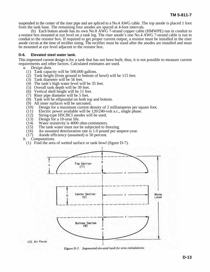
D-6. Elevated steel water tank.This impressed current design is for a tank that has not been built; thus, it is not possible to measure currentrequirements and other factors. Calculated estimates are used.
a. Design data.(1) Tank capacity will be 500,000 gallons.(2) Tank height (from ground to bottom of bowl) will be 115 feet.(3) Tank diameter will be 56 feet.(4) The tank’s high water level will be 35 feet.(5) Overall tank depth will be 39 feet.(6) Vertical shell height will be 11 feet.(7) Riser pipe diameter will be 5 feet.(8) Tank will be ellipsoidal on both top and bottom.(9) All inner surfaces will be uncoated.(10) Design for a maximum current density of 2 milliamperes per square foot.(11) Electric power available will be 120/240-volt a.c., single phase.(12) String-type HSCBCI anodes will be used.(13) Design for a 10-year life.(14) Water resistivity is 4000 ohm-centimeters.(15) The tank water must not be subjected to freezing.(16) An assumed deterioration rate is 1.0 pound per ampere-year.(17) Anode efficiency (assumed) is 50 percent.
b. Computations.(1) Find the area of wetted surface or tank bowl (figure D-7).
AB • 2 r a 2 • r 2,
AB • 2 × 3.1416 × 28 ft × 14 ft 2 • 28 ft 2,
W • YSIE
,
W • (10 yr)(1.0 lb/A• yr)(15.2A)0.50
,
TM 5-811-7
D-14
(eq D-6)
(a) For the top section (T)—A = 2 • rx (approximately),T
where r == 28 feet (tank radius), x = 10 feet. Thus,A =2 x 3.1416 x 28 ft x 10 ftT
A= 1759 sq ft.(b) For the center section (C)—A =2 • rh, (eq D-5)c
where r = 28 feet (tank radius) and h = 11 feet. Thus,` A = 2 x 3.1415 x 28 ft x 11 ftc
A = 1935 sq ft.c
(c) For the bottom section (b)—
where r = 28 feet (tank radius) and a 14 feet. Thus,
A = 3894 sq ft.B
(d) Therefore, the total wetted area of the tank bowl is—A + A +A or 7588 sq ft.T C B
(2) Find the riser pipe•s area using equation D-7:A = 2 • r h , (eq D-7)r R R
where r = 2.5 feet (riser radius) and h = 115 feet (riser height). Thus,R R
A = 2 x 3.1416 x 2.5 ft x 115 ftR
A = 1806 sq ftR
(3) Find the maximum design current for the tank:I = 2.0 mA/sq ft x 7588 sq ftT
I = 15,176 mA or 15.2 A.T
(4) Find the maximum design current for the riser:I = 2.0 mA/sq ft x 1806 sq ftR
I 3612 mA or 3.62 A.r
(5) Find the minimum weight of tank anode material needed (eq C-1 from appendix C):
where Y = 10 years, S = 1.0 pound per ampere-year, E = 0.50, and I = 15.2 amperes. Thus,
W = 304 lb.
W • YSIE
,
W • (10 yr)(1.0 lb/A• yr)(3.62A)0.50
,
r • 56 ft × 102(3.1416 • 10)
C • 2 × 3.1416 × 22 ft10
TM 5-811-7
D-15
(6) Compute the minimum weight of riser anode material needed (eq C-1):
where Y = 10 years, S = 1.0 pound per ampere-year, I = 3.62 amperes, and E = 0.50.
W = 72.4 lb.
(7) Find the main anode circle's radius using equation D-8:
r = (DN)/2(• + N) (eq D-8)
where D = 56 feet and N = 10 (assumed number of anodes). Thus,
r = 560/26.28
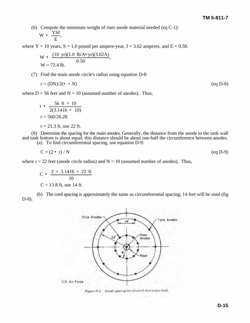
r = 21.3 ft, use 22 ft.(8) Determine the spacing for the main anodes. Generally, the distance from the anode to the tank wall
and tank bottom is about equal; this distance should be about one-half the circumference between anodes.(a) To find circumferential spacing, use equation D-9:
C = (2 • r) / N (eq D-9)
where r = 22 feet (anode circle radius) and N = 10 (assumed number of anodes). Thus,
C = 13.8 ft, use 14 ft.
(b) The cord spacing is approximately the same as circumferential spacing; 14 feet will be used (figD-8).
15.2 A10 × 0.025 A
• 60.8 (use 61 anodes per string.
TM 5-811-7
D-16
(9) Select the main anodes.(a) The anode unit size chosen is 1c-inch outside diameter, ¾-inch inside diameter, and 9 inches
long. This is a standard sausage-type anode that weighs 1 pound and has a surface area of 0.25 square foot.(b) The minimum number of anode units per anode string (N), based on a required weight of 304
pounds and 10 anode strings, is computed as follows:
N = 304/(10 x 1)
N = 30.4, use 31 units per string.
(c) Because the inside tank surfaces are uncoated, a maximum structure-to-electrolyte voltage is nota limiting factor. However, because it is desired to hold the anode current at or below the manufacturer'srecommended discharge rate of 0.025 ampere per anode for this type anode, the minimum number of anodeswill be—
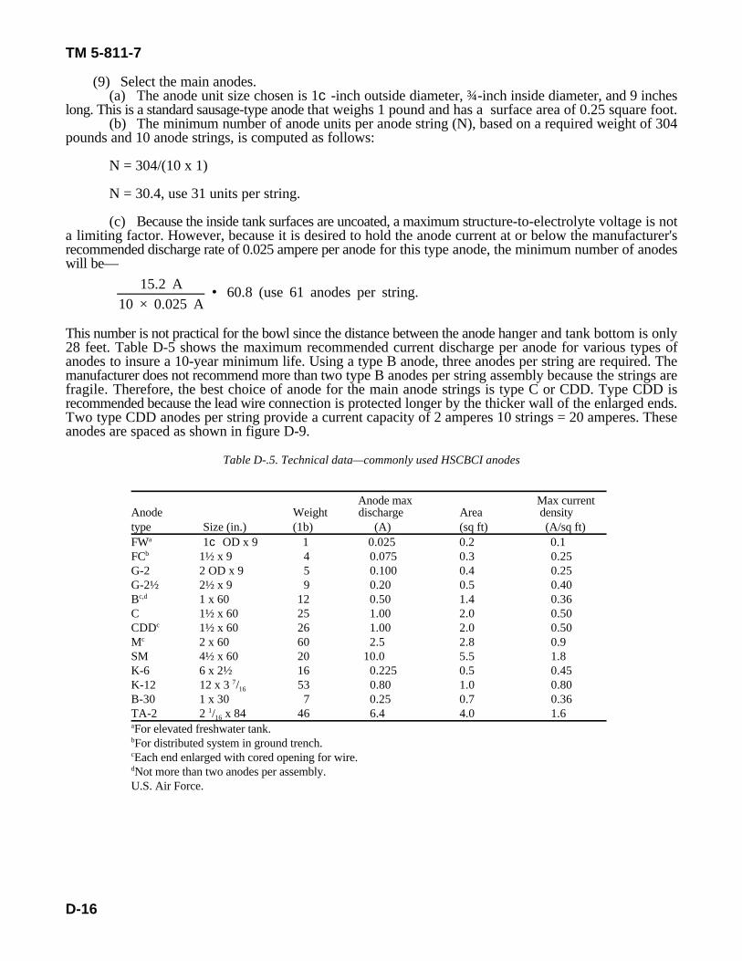
This number is not practical for the bowl since the distance between the anode hanger and tank bottom is only28 feet. Table D-5 shows the maximum recommended current discharge per anode for various types ofanodes to insure a 10-year minimum life. Using a type B anode, three anodes per string are required. Themanufacturer does not recommend more than two type B anodes per string assembly because the strings arefragile. Therefore, the best choice of anode for the main anode strings is type C or CDD. Type CDD isrecommended because the lead wire connection is protected longer by the thicker wall of the enlarged ends.Two type CDD anodes per string provide a current capacity of 2 amperes 10 strings = 20 amperes. Theseanodes are spaced as shown in figure D-9.
Table D-.5. Technical data—commonly used HSCBCI anodes
Anode max Max currentAnode Weight discharge Area densitytype Size (in.) (1b) (A) (sq ft) (A/sq ft)FW 1c OD x 9 1 0.025 0.2 0.1a
FC 1½ x 9 4 0.075 0.3 0.25b
G-2 2 OD x 9 5 0.100 0.4 0.25G-2½ 2½ x 9 9 0.20 0.5 0.40B 1 x 60 12 0.50 1.4 0.36c,d
C 1½ x 60 25 1.00 2.0 0.50CDD 1½ x 60 26 1.00 2.0 0.50c
M 2 x 60 60 2.5 2.8 0.9c
SM 4½ x 60 20 10.0 5.5 1.8K-6 6 x 2½ 16 0.225 0.5 0.45K-12 12 x 3 / 53 0.80 1.0 0.807
16
B-30 1 x 30 7 0.25 0.7 0.36TA-2 2 / x 84 46 6.4 4.0 1.61
16
For elevated freshwater tank.a
For distributed system in ground trench.b
Each end enlarged with cored opening for wire.c
Not more than two anodes per assembly.d
U.S. Air Force.
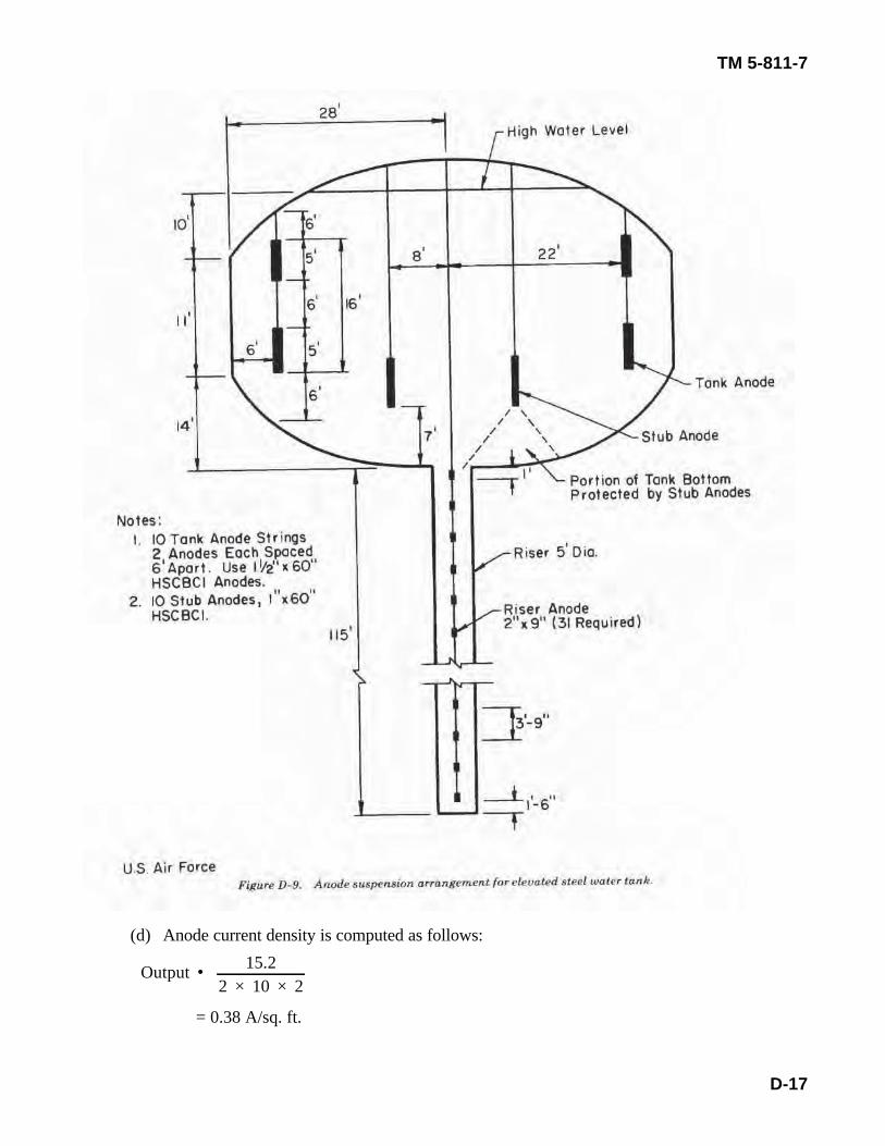
Output • 15.22 × 10 × 2
TM 5-811-7
D-17
(d) Anode current density is computed as follows:
= 0.38 A/sq. ft.
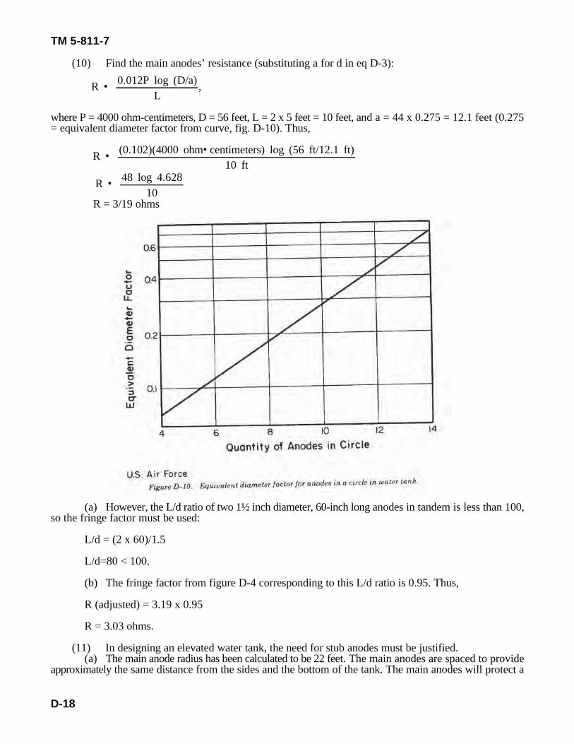
R • 0.012P log (D/a)L
,
R • (0.102)(4000 ohm• centimeters) log (56 ft/12.1 ft)10 ft
R • 48 log 4.62810
TM 5-811-7
D-18
(10) Find the main anodes’ resistance (substituting a for d in eq D-3):
where P = 4000 ohm-centimeters, D = 56 feet, L = 2 x 5 feet = 10 feet, and a = 44 x 0.275 = 12.1 feet (0.275= equivalent diameter factor from curve, fig. D-10). Thus,
R = 3/19 ohms
(a) However, the L/d ratio of two 1½ inch diameter, 60-inch long anodes in tandem is less than 100,so the fringe factor must be used:
L/d = (2 x 60)/1.5
L/d=80 < 100.
(b) The fringe factor from figure D-4 corresponding to this L/d ratio is 0.95. Thus,
R (adjusted) = 3.19 x 0.95
R = 3.03 ohms.
(11) In designing an elevated water tank, the need for stub anodes must be justified.(a) The main anode radius has been calculated to be 22 feet. The main anodes are spaced to provide
approximately the same distance from the sides and the bottom of the tank. The main anodes will protect a
TM 5-811-7
D-19
length along the tank bottom equal to 1½ times the spacing of the anode from the bottom.(b) The anode suspension arrangement for the tank being considered is shown in figure D-9. It can
be seen that stub anodes are required for this design. Ten stub anodes are spaced equally on a circumferencewith a radius of 8 feet in a way shown in figure D-8. For smaller diameter tanks, stub anodes may not berequired.
(12) Find the current division between main and stub anodes.(a) The area of tank bottom protected by stub anodes is found by equation D-10 (fig D-9):A = • (r - r ), (eq D-10)s 2 1
2 2
where r = 13 feet (protected segment radius) and r = 2.5 feet (riser radius). Thus,2 1
A = 3.1416 (132 sq ft - 2.52 sq ft)s
A = 3.1416 x 162.75s
A = 511.3 sq ft.s
(b) The maximum current for stub anodes is therefore—I = 2.0 x 511.3s
I = 1022.6 milliamperes or 1.02 amperes.s
(c) The maximum current for the tank bowl is 15.2 amperes.(d) The maximum current for main anodes is—I = 15.2A - 1.02Am
I = 14.2A.m
(13) Find the rectifier voltage rating.(a) The electrical conductor to the main anode is wire size No.2 AWG, rated at 0.159 ohm per 1000
feet, and has an estimated length of 200 feet. Thus, the resistance of the wire, R, is:200 ft
R = ——— x 0.159 ohm = 0.032 ohm.1000 ft
(b) For the voltage drop in the main anode feeder—E = IR,
where I = 14.2 amperes and R = 0.032 ohm. Thus,E = 14.2 A x 0.032 ohmE = 0.45 V.(c) For the voltage drop through the main anodes—E = IR,where I = 14.2 amperes and R = 3.03 ohms. Thus,E = 14.2 A x 3.03 ohms.E = 43.0 V.(d) The total voltage drop in main anode circuit is thus—E = 0.45 + 43.0T
E = 43.45 or 45 V.T
Use a multiplying factor (safety factor) of 1.5 to get 67.5 volts.
R • 0.012P log (D/a)L
,
R • (0.012)(4000 ohm• centimeters) log (56 ft/4.4 ft)5 ft
R • 48 log 12.735
R • 48 × 1.1055
TM 5-811-7
D-20
(14) Select the stub anodes. Because it is desirable to use as small an anode as possible withoutexceeding the manufacturers' recommended rate, try using type FC, HSCBCI anode that measures 1½-inchesby 9 inches. Use one anode per string as shown in figure D-9. Anode current density is computed as follows:
Output = 1.02/(10 x 0.03) = 0.34 A/sq ft.
Because this exceeds the recommended maximum anode current density shown in table D-1, the type Banode is the best choice.
(15) Find the stub anodes' resistance (from eq D-3):
where P = 4000 ohm-centimeter, D = 56 feet, L = 5 feet, and a = 16 0.275 = 4.4 feet (factor from fig D-10)
R = 10.6 ohms.
L/d = 60/1 = 60 < 100
Using the fringe factor from curve figure D-4, 0.90—
R (adjusted) = 10.6 x 0.90 = 9.54 ohms.
(16) Find the voltage drop in the stub anode circuit.(a) The electrical conductor to the stub anodes is wire size No.2 AWG, rated at 0.159 ohm/1000
feet, and has an estimated length of 200 feet. Thus,
R = (200 ft/1000 ft) x 0.159 ohm/1000 ft = 0.032 ohm.
(b) To find the voltage drop in the stub anode feeder—
E = IR
where I = 1.02 amperes and R = 0.032 ohm. Thus,
E = 1.02 A x 0.032 ohm
E = 0.033 V.
(c) Find the voltage drop in anode suspension conductors. First, compute the resistance (R) for anestimated 50-foot-long, No.2 AWG wire rated at 0.159 ohm per 1000 feet:
R = (50/1000) x 0.159 = 0.008 ohm.
E = IR,
where I = 1.02/10 = 0.102 ampere and R = 0.008 ohm. Thus,
E = 1.02 A x 0.008 ohm
E = negligible.
TM 5-811-7
D-21
(d) Find the voltage drop through the stub anodes given that the rectifier output is 80 volts, theanode current (I) is 1.02 amperes, and the resistance (R) is 9.54 ohms:
E = IR
E = 1.02 A x 9.54 ohms
E = 9.73 V.
(e) Find the total voltage drop in the stub anode circuit.
E = 0.033 + 9.73T
E = 9.76 V.T
(f) Since the stub anode voltage is below the 45 volts calculated for the main tank anode circuit, thenecessary current adjustment can be made through a variable resistor in the stub anode circuit.
(17) Choose a stub anode circuit variable resistor.(a) The resistor should be able to carry the maximum anode circuit current and have enough
resistance to reduce the anode current by one-half when full rectifier voltage is applied to the anode circuit.(b) Stub anode circuit data are: rectifier output = 80 volts, anode current = 1.02 amperes, and anode
resistance = 9.54 ohms.(c) The variable resistor rating is found by–
R = E/I,
where E = 80 volts and I = 1.02/2 or 0.51 ampere. Thus,
R=80/0.51
R = 156.9 ohms
Resistor's ohmic value = 156.9-9.54
= 147.4 ohms.
To find the resistor's wattage rating —
P = I R (eq D-11)2
P = (1.02) x 147.42
P = 153.4 W.
The commercially available resistor that nearest meets the above requirements is a 175-watt, 200-ohm,1-ampere size.
(18) Find the riser anodes’ resistance. To get the maximum desired current in the riser (3.62 amperes),the resistance limit is calculated as follows:
R = E/1,
where E = 43.45 volts and I = 3.62 amperes. Thus,
R = 43.5 V/3.62 A
R = 12.0 ohms
(19) Design the riser anode.(a) Type FW (1-c-inch by 9-inch) string-type anodes cannot be used in the riser because the
maximum anode current discharge of 0.025 ampere per anode would be exceeded. The number of type FWanodes required would be 145, placed continuously throughout the riser. This number is too high. The bestchoice of anode for a flexible riser string is type G-2 (2-inch by 9-inch) high-silicon cast-iron anode.
R • 0.012P log (D/d)L
,
L • 0.012P lob (D/d)R
,
L • (0.012)(4000 ohm• cm) log (5 ft/0.166 ft)12 ohms
L • 48 × log 30.112
L • 48 × 1.47912
3.62 A0.1 A
• 36.
R • 0.012P log (D/d)L
,
R • (0.012)(4000 ohm• cm) log (5 ft/0.166 ft)27 ft
R • 48 × log 30.127
R • 200 ft1000 ft
× 0.159 ohm1000 ft
TM 5-811-7
D-22
(b) The number of units required is found from equation D-3:
or
where P = 4000 ohm-centimeters, D = 5 feet, d = 2 inches or 0.166 foot, and R = 12 ohms. Thus,
L = 5.92 ft.
The nubmer of units is thus —
5.92/0.75 = 7.9 or 8 units.
For proper current distribution in the riser pipe, the anode units should not be placed too far apart. It isgenerally considered that each anode unit protects a length along the riser pipe equal to 1½ times the spacingof the anode from the riser pipe wall. Therefore, for a riser height of 115 feet, spacing (center of anode totank wall) should be 2.5 feet. The riser length protected by one anode is 1.5 x 2.5 = 3.75 feet, so the numberof units required is 115/3.75=30.7 or 31 units. To satisfy the maximum anode discharge current for a G-2anode–
Therefore, 36 anodes are needed instead of 31 or 8.(c) To find the anode resistance using 36 anode units, use equation D-3:
where P = 4000 ohm-centimeters, D =5 feet, d = 2 inches or 0.166 foot, and L =36 x 9 inches =324 inchesor 27 feet. Thus,
R = 2.63 ohms
The L/d ratio for the riser anode string is 324/2 or 162; thus, no fringe factor correction is used.(20) Find the voltage drop in the riser anode circuit.
(a) Electrical conductor to riser anodes. For a wire size No.2 AWG, 0.159 ohm per 1000 feet, andestimated length 200 feet, the resistance (R) is–
R • 130 ft1000 ft
× 0.159 ohm1000 ft
TM 5-811-7
D-23
R = 0.032 ohm.
(b) Find the voltage drop in riser anode feeder by–
E = IR,
where I = 3.62 amperes and R = 0.032 ohm. Thus,
E = 3.62 A 0.032 ohm
E = 0.116 V.
(c) Find the voltage drop in the riser anode suspension cables for wire size No.2 AWG, 0.159 ohmper 1000 feet rating, and estimated length 130 feet;
R = 0.02 ohm.
E = IR
where 1=3.62/2=1.81 amperes average (single current does not flow the full length of the anode string) andR = 0.02 ohm. Thus,
E = 1.81 A x 0.02 ohm
E = 0.04 V.
(d) Find the voltage drop through riser anodes:
E = IR,
where I = 3.62 amperes and R = 2.63 ohms. Thus,E = 3.62 A x 2.63 ohmsE = 9.52 V.(e) Find the total voltage drop in the riser anode circuit:E = 0.116V + 0.04V + 9.52VT
E = 9.68 volts.T
(21) Select the riser anode circuit variable resistor.(a) Criteria for the variable resistor are the same as given for the stub anode resistor.(b) Riser anode circuit data — rectifier output = 80 volts, anode current = 3.62 amperes, anode
resistance = 2.63 + 0.032+0.02 = 2.68 ohms.(c) Variable resistor rating (resistor should reduce anode current by one-half when full rectifier
voltage is applied)–r = E/I,
where E = 80 volts and I = 3.62/2 = 1.81 amperes. Thus,R = 80 V - l.18 AR = 44.2 ohms.
Resistor ohmic value = 44.2 ohms -2.68 ohms = 41.5 ohms.
Resistor wattage rating = (3.62 A) x 41.5 ohms = 543.8 W.2
(d) The commercially available resistor that nearest meets the size requirements is a 750-watt, 50-ohm, 3.87-ampere model. This rheostat is 10 inches in diameter and 3 inches deep and is fairly expensive. It
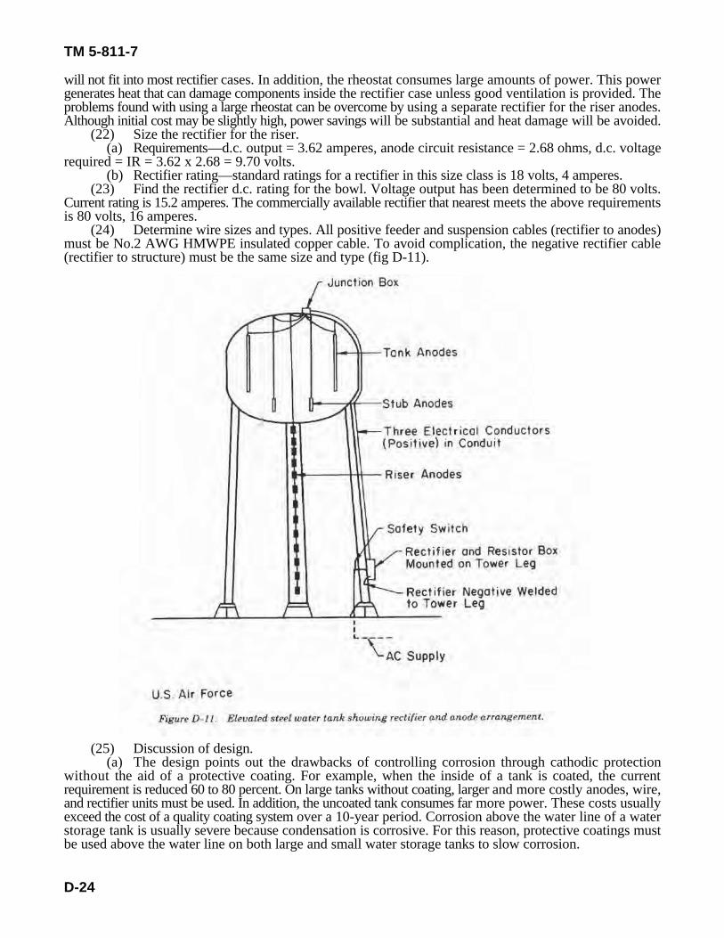
TM 5-811-7
D-24
will not fit into most rectifier cases. In addition, the rheostat consumes large amounts of power. This powergenerates heat that can damage components inside the rectifier case unless good ventilation is provided. Theproblems found with using a large rheostat can be overcome by using a separate rectifier for the riser anodes.Although initial cost may be slightly high, power savings will be substantial and heat damage will be avoided.
(22) Size the rectifier for the riser.(a) Requirements—d.c. output = 3.62 amperes, anode circuit resistance = 2.68 ohms, d.c. voltage
required = IR = 3.62 x 2.68 = 9.70 volts.(b) Rectifier rating—standard ratings for a rectifier in this size class is 18 volts, 4 amperes.
(23) Find the rectifier d.c. rating for the bowl. Voltage output has been determined to be 80 volts.Current rating is 15.2 amperes. The commercially available rectifier that nearest meets the above requirementsis 80 volts, 16 amperes.
(24) Determine wire sizes and types. All positive feeder and suspension cables (rectifier to anodes)must be No.2 AWG HMWPE insulated copper cable. To avoid complication, the negative rectifier cable(rectifier to structure) must be the same size and type (fig D-11).
(25) Discussion of design.(a) The design points out the drawbacks of controlling corrosion through cathodic protection
without the aid of a protective coating. For example, when the inside of a tank is coated, the currentrequirement is reduced 60 to 80 percent. On large tanks without coating, larger and more costly anodes, wire,and rectifier units must be used. In addition, the uncoated tank consumes far more power. These costs usuallyexceed the cost of a quality coating system over a 10-year period. Corrosion above the water line of a waterstorage tank is usually severe because condensation is corrosive. For this reason, protective coatings mustbe used above the water line on both large and small water storage tanks to slow corrosion.
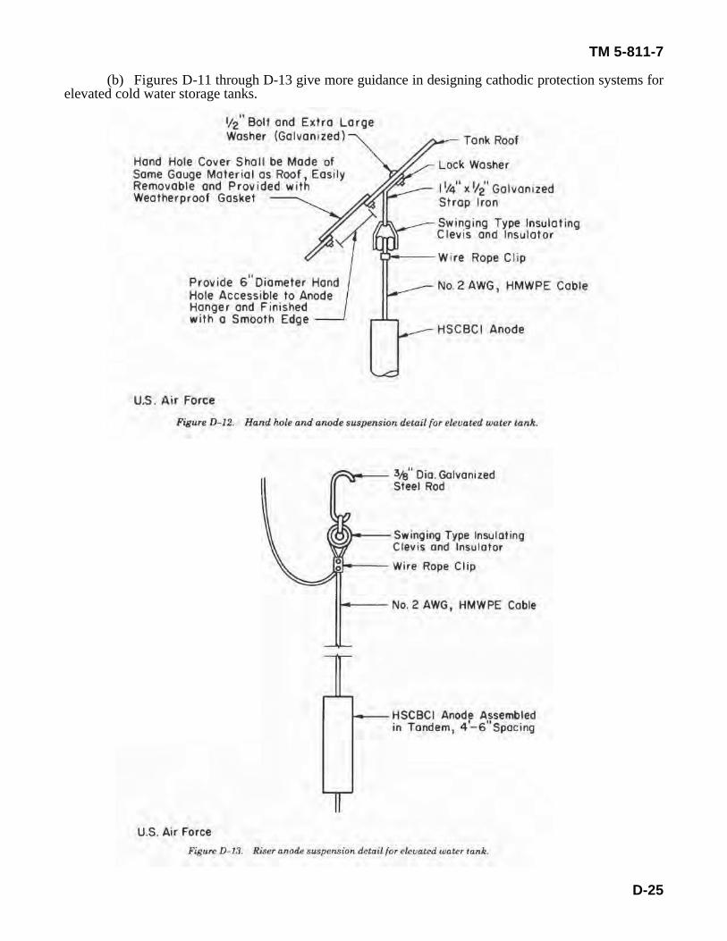
TM 5-811-7
D-25
(b) Figures D-11 through D-13 give more guidance in designing cathodic protection systems forelevated cold water storage tanks.
TM 5-811-7
D-26
(c) HSCBCI was chosen for this design purely as an example. It does not mean this material is betterthan other anode types. Other acceptable anode materials include aluminum and platinized titanium orniobium.
(d) For this design, silicon cells should be specified for the rectifier that protects the bowl, andselenium cells should be specified for the rectifier that protects the riser. Silicon cells operate more efficientlyat high d.c. output voltages than selenium cells, but require elaborate surge and overload protection. Thisprotection is not economical in the low power consuming units. A guide for choosing rectifying cells is asfollows: use silicon cells for single-phase rectifiers operated above 72 volts d.c. or for three-phase rectifiersoperated above 90 volts d.c.; use newer, nonaging selenium for single-phase rectifiers operated below 72volts d.c. or three-phase rectifiers operated below 90 volts d.c.
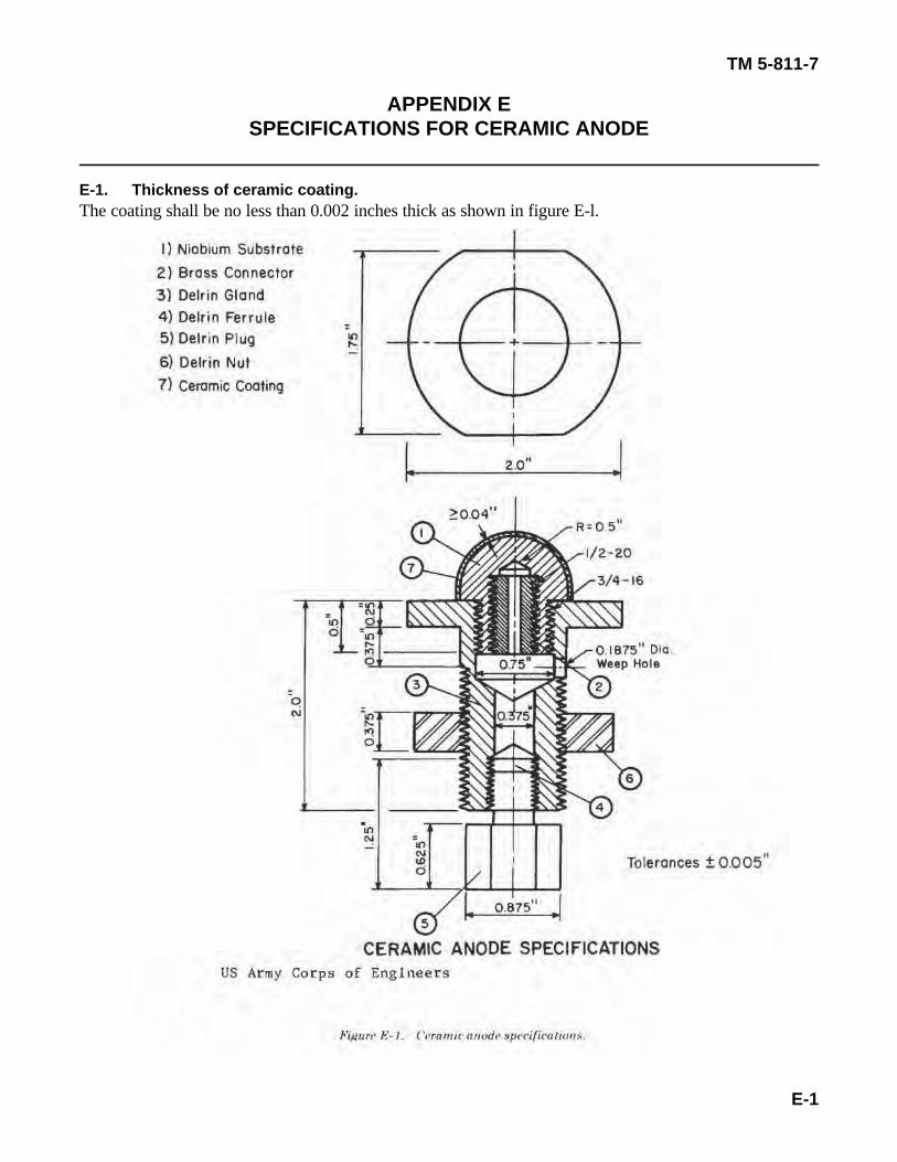
TM 5-811-7
E-1
APPENDIX ESPECIFICATIONS FOR CERAMIC ANODE
E-1. Thickness of ceramic coating.The coating shall be no less than 0.002 inches thick as shown in figure E-l.
TM 5-811-7
E-2
E-2. Dissolution rate.For a current density of 20 amperes per square meter—
- Freshwater, 10 grams per ampere-year.- Saltwater, 15 grams per ampere-year.
E-3. Resistivity.The anode's resistivity shall be 1500 ohm-centimeters.
E-4. Impact resistance.A Gardner heavey-duty impact tester (Pacific Scientific, West Silver Spring, MD) shall be used. The anodewill be screwed into a modified holder and a round-nose punch 0.625 inches in diameter will be placed onthe specimen. A 2-pound weight shall be raised to the desired height in a graduated tube and released.Damage to coatings, such as chipping or cracking, should be observed visually or with low-power (10X)magnification. The sample should withstand a force of 32 inch-pounds when the weight is dropped; the punchshould be located within an area c inch from the center of the anode without observable damage.
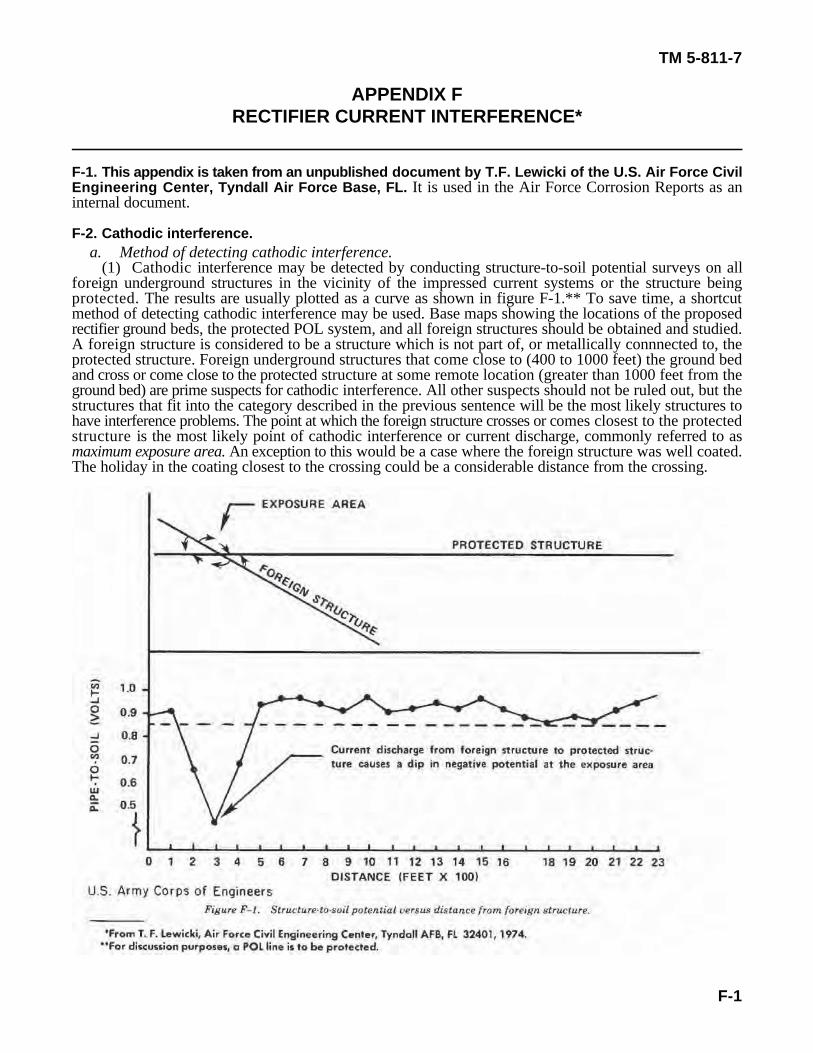
TM 5-811-7
F-1
APPENDIX FRECTIFIER CURRENT INTERFERENCE*
F-1. This appendix is taken from an unpublished document by T.F. Lewicki of the U.S. Air Force CivilEngineering Center, Tyndall Air Force Base, FL. It is used in the Air Force Corrosion Reports as aninternal document.
F-2. Cathodic interference.a. Method of detecting cathodic interference.
(1) Cathodic interference may be detected by conducting structure-to-soil potential surveys on allforeign underground structures in the vicinity of the impressed current systems or the structure beingprotected. The results are usually plotted as a curve as shown in figure F-1.** To save time, a shortcutmethod of detecting cathodic interference may be used. Base maps showing the locations of the proposedrectifier ground beds, the protected POL system, and all foreign structures should be obtained and studied.A foreign structure is considered to be a structure which is not part of, or metallically connnected to, theprotected structure. Foreign underground structures that come close to (400 to 1000 feet) the ground bedand cross or come close to the protected structure at some remote location (greater than 1000 feet from theground bed) are prime suspects for cathodic interference. All other suspects should not be ruled out, but thestructures that fit into the category described in the previous sentence will be the most likely structures tohave interference problems. The point at which the foreign structure crosses or comes closest to the protectedstructure is the most likely point of cathodic interference or current discharge, commonly referred to asmaximum exposure area. An exception to this would be a case where the foreign structure was well coated.The holiday in the coating closest to the crossing could be a considerable distance from the crossing.
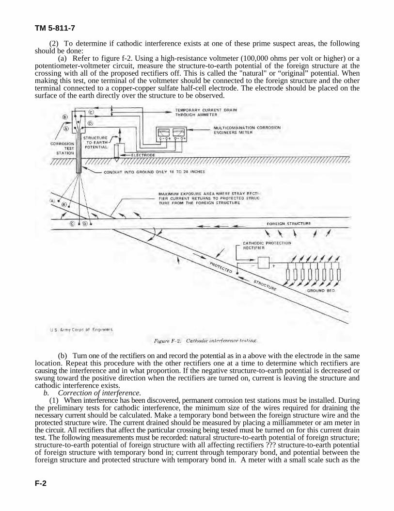
TM 5-811-7
F-2
(2) To determine if cathodic interference exists at one of these prime suspect areas, the followingshould be done:
(a) Refer to figure f-2. Using a high-resistance voltmeter (100,000 ohms per volt or higher) or apotentiometer-voltmeter circuit, measure the structure-to-earth potential of the foreign structure at thecrossing with all of the proposed rectifiers off. This is called the "natural" or “original” potential. Whenmaking this test, one terminal of the voltmeter should be connected to the foreign structure and the otherterminal connected to a copper-copper sulfate half-cell electrode. The electrode should be placed on thesurface of the earth directly over the structure to be observed.
(b) Turn one of the rectifiers on and record the potential as in a above with the electrode in the samelocation. Repeat this procedure with the other rectifiers one at a time to determine which rectifiers arecausing the interference and in what proportion. If the negative structure-to-earth potential is decreased orswung toward the positive direction when the rectifiers are turned on, current is leaving the structure andcathodic interference exists.
b. Correction of interference.(1) When interference has been discovered, permanent corrosion test stations must be installed. During
the preliminary tests for cathodic interference, the minimum size of the wires required for draining thenecessary current should be calculated. Make a temporary bond between the foreign structure wire and theprotected structure wire. The current drained should be measured by placing a milliammeter or am meter inthe circuit. All rectifiers that affect the particular crossing being tested must be turned on for this current draintest. The following measurements must be recorded: natural structure-to-earth potential of foreign structure;structure-to-earth potential of foreign structure with all affecting rectifiers ??? structure-to-earth potentialof foreign structure with temporary bond in; current through temporary bond, and potential between theforeign structure and protected structure with temporary bond in. A meter with a small scale such as the
• Et
Jd
•• Er
It
It •Er × Id
• Et
,
TM 5-811-7
F-3
(eq. F-1)
M. C. Miller multicombination corrosion engineer's meter that has ammeter scales as large as 10 amperes oras small as 20 milliamperes or less and a number of small voltmeter scales should be used. The total currentrequired in a resistance bond to clear the interference current leaving the foreign structure can be calculatedby using the following simple algebraic formula:
and:
where • E = E - E = change in structure-to-earth potential required to clear interference; E = E - Er fn fr t fn frd= change in structure-to-earth potential caused by the temporary bond; E = natural structure-to-earthfnpotential of the foreign structure; E = structure-to-earth potential of foreign structure with all affectingfrrectifiers on; E structure-to-earth potential of foreign structure with temporary bond in; I current throughfrd dtemporary bond; and T = total current required through final resistance bond to correct cathodic interferencetcaused by all of the rectifiers. The minimum size of wire required should also be calculated, but wire smallerthan No.12 AWG should not be used because of poor mechanical strength. The permanent test station shouldinclude two wires thermit welded or brazed to the foreign structure and two wires thermit welded or brazedto the protected structure. This will allow one wire to be used as a current drain while the other is used tomeasure potential.
(2) After the permanent test station has been installed, the resistance bond can be most easily installedas follows: bare nichrome resistance wire in the range of ½ ohm per foot, or 1 ohm per foot, or 10 ohms perfoot, depending on the total resistance needed, should be used.
(a) Since as many as three rectifiers may be involved in an interference bond in the hydrant refuelingarea, a current interrupter in the rectifier circuit for interrupting all the rectifiers simultaneously would notbe practical. All the rectifiers should be turned on and off manually if more than one rectifier is involved. Ifonly one rectifier causes the interference at a particular site, a current interruptor should be placed in the a.c.circuit to interrupt the current output.
(b) Place a copper-copper sulfate half-cell electrode on the surface of the earth at the point ofgreatest exposure. Measure and record the natural structure to-earth potential of the foreign structure withall interfering electrical circuits off.
(c) After all interfering sources are turned on, insert a portion of nichrome resistance wire betweenthe foreign structure wire and the protected structure wire and observe the structure-to-earth potential of theforeign structure. Increase or decrease the amount of nichrome in the circuit until the structure-to-earthpotential of the foreign (the interfered-with) structure becomes equal to the natural potential measured in babove. The current flowing through the resistance bond is now the correct amount and the interference hasbeen cleared. No ammeters or additional test leads can be in series with the resistance bond when this testis made.
(d) Mark or note the exact contact of the nichrome resistance wire with the test station lead wires.Add ¼ or ½ inch to each end of these points and cut the nichrome. Crimp an eyelet or fork solderlessterminal at the exact points where the nichrome contacted the test station lead wires. A permanent resistorhas now been fabricated with the exact resistance required for the resistance bond. This resistance may beinstalled, removed, and reinstalled for testing purposes without changing the value of the resistance. Installthe fabricated resistor in the test station and check to see that the natural structure-to-earth potential isachieved. If the potential measured is even a slight amount off, reduce the length of the nichrome or fabricatea longer piece until the natural structure-to-earth potential is achieved with all rectifiers on and resistancebond in (E will now equal E ). When the proper resistor has been fabricated, the wire should be coiledfn frdon a pencil to make a neat, compact coil that can be installed inside of the test stations without shorting tothe sides of the test station box or the terminals. After the pencil has been removed, the bare nichrome shouldnot be wrapped with tape to allow proper cooling. Primer and tape may be placed inside the test station boxto prevent a short. The amount of current flowing through the bond will be equal to the value calculated in
TM 5-811-7
F-4
paragraph b above. An ammeter cannot be placed in series with the resistance bond because the resistancewould be increased slightly and the current through the bond would be reduced.
c. Bond installation. The installation of cathodic interference resistance bonds will reduce the cathodicprotection current coming onto the protected POL structure from the electrolyte by an amount equal to thetotal current flowing through all of the bonds, This total bond current originates from the rectifiers installedto protect the protected structure (the POL system in this case). The portion of rectified or d.c. current equalto the total bond current does not contribute to corrosion mitigation of the POL system. Therefore, therectified or d.c. current output may have to be increased as bonds are installed to maintain an adequate POLstructure-to-earth potential of -0.85 volt.
TM 5-811-7
BIBLIOGRAPHY
Applegate, L. M., Cathodic Protection, McGraw-Hill Book Company, New York, 1960.Bryan, W. T., Designing Impressed Current Cathodic Protection Systems With Durco Anodes, The Duriron
Company, Dayton, 011, 1970.Lewicki, T. F., Rectifier Current Interference, U.S. Air Force Civil Engineering Center, Tyndall Air Force
Base, FL, 1974.Myers, J. R. and Aimone, M. A., Corrosion Control for Underground Steel Pipelines: A Treatise on
Cathodic Protection, James R. Myers and Associates, Franklin, OH, 1980.Parker, M. E., “Corrosion by Soils," NACE Basic Corrosion Course (A. Brasunus, Ed.), National
Association of Corrosion Engineers, Houston, TX, 1980.Peabody, A. W., “Principles of Cathodic Protection,” NA CE Basic Corrosion Course (A. Brasunus, Ed.),
National Association of Corrosion Engineers, Houston, TX, 1980.Segan, E. and Kumar, A., Preliminary Investigation of Ceramic-Coated Anodes for Cathodic Protection,
Technical Report M-333/A133440 U.S. Army Construction Engineering Research Laboratory,Champaign, IL, 1983.
The Custom VIP Cathodic VIP Cathodic Protection Rectifier. Technical Bulletin, Goodall Electric, Inc., FortCollins, CO, January 1982.
TM 5-811-7
GLOSS-1
GLOSSARY
adsorption - taking up one substance at the surface of another; tendency of all solids to condense on theirsurfaces a layer of any gas or solute that contacts such solids.
aeration cell (oxygen cell) - electrolytic cell in which a difference in oxygen concentration at the electrodesexists, producing corrosion.
amphoterics - materials subject to attack by both acid and alkaline environments; include aluminum, zinc, andlead (commonly used in construction).
anaerobic - free of air or uncombined oxygen; anaerobic bacteria are those that do not use oxygen in theirlife cycle.
anion - a negatively charged ion that migrates toward the anode under influence of a potential gradient.*anode - electrode at which oxidation of its surface or some component of the solution is occurring
(opposite: cathode).*bell hole - excavation to expose a buried structure.cathode - electrode at which reduction of its surface or some component of the solution is occurring
(opposite: anode).cathodic corrosion - corrosion resulting from a structure's cathodic condition, usually caused by the reaction
of alkaline products of electrolysis with an amphoteric metal.*cathodic protection - technique to prevent metal surface corrosion by making that surface the cathode
of an electrochemical cell.cation - positively charged ion of an electrolyte that migrates toward the cathode under the influence of a
potential gradient.concentration cell - electrolytic cell in which a difference in electrolyte concentration exists between anode
and cathode, producing corrosion.*continuity bond - metallic connection that provides electrical continuity.*corrosion - deterioration of a material, usually a metal, because of a reaction with its environment.* current density - current per unit area.*electrical isolation - condition of being electrically separated from other metallic structures or the
environment.*electrosmotic effect - passage of a charged particle through a membrane under the influence of a voltage;
soil can act as the membrane.*electrode potential - potential of an electrode as measured against a reference electrode. The electrode
potential includes no loss of potential in the solution due to current passing to or from the electrodes (thatis, it represents the reversible work required to move a unit charged from the electrode surface throughthe solution to the reference electrode).
electrolyte - chemical substance or mixture, usually liquid, containing ions that migrate in an electric field;examples are soil and seawater.
electromotive force series (EMF series) - list of elements arranged according to their standard electrodepotentials; the sign is positive for elements with potentials cathodic to hydrogen and negative for thoseelements with potentials anodic to hydrogen.
*foreign structure - any structure not intended to be part of the system of interest.*galvanic anode - metal that, because of its relative position in the galvanic series, provides sacrificial
protection in the galvanic series when coupled in an electrolyte. These anodes are the current source inone type of cathodic protection.
galvanic cell - corrosion cell in which anode and cathode are dissimilar conductors, producing corrosionbecause of their innate difference in potential.
*galvanic series - list of metals and alloys arranged according to their relative potentials in a givenenvironment.
*holiday - coating discontinuity that exposes the metal surface to the environment.hydrogen overvoltage - voltage characteristic for each metal-environmental combination above which
hydrogen gas is liberated.
____________________*Definition is from NACE Standard RP-01.
TM 5-811-7
GLOSS-2
impressed current - direct current supplied by a power source external to the electrode system.*insulating coating system - all components that comprise the protective coating, the sum of which provides
effective electrical insulation of the coated structure.*interference bond - metallic connection designed to control electrical interchange between metallic systems.ion - electrically charged atom or molecule.*IR drop - voltage across a resistance according to Ohm's Law.*line current - direct current flowing on a pipeline.local action - corrosion caused by local cells on a metal surface.mill scale - heavy oxide layer formed during hot fabrication or heat-treatment of metals. Applied chiefly to
iron and steel.Molality - concentration of a solution expressed as the number of gram molecules of the dissolved substance
per 1000 grams of solvent.PH - measure of hydrogen ion activity defined by pH log 10 (1/aH+), where aH+ = hydrogen ion activity =
molal concentration of hydrogen ions multiplied by ion activity coefficient (a = 1 for simplifiedcalculations).
polarization - deviation from the open circuit potential of an electrode resulting from the passage of current.*reference electrode - device for which the open circuit potential is constant under similar conditions of
measurement.* reverse-current switch - device that prevents the reversal of direct current through a metallic conductor.*stray current - current flowing through paths other than the intended circuit.*stray current corrosion - corrosion resulting from direct current flow through paths other than the intended
circuit.*structure-to-electrolyte voltage (also structure-to-soil potential or pipe-to-soil potential) - voltage difference
between a buried metallic structure and the electrolyte, measured with a reference electrode in contactwith the electrolyte.
*structure-to-structure voltage (also structure-to-structure potential) - difference in voltage between metallicstructures in a common electrolyte.
*voltage - electromotive force, or a difference in electrode potentials, expressed in volts.
TM 5-811-7
The proponent agency of this publication is the Office of the Chief of Engineers, UnitedStates Army. Users are invited to send comments and suggested improvements on DA Form2028 (Recommended Changes to Publications and Blank Forms) direct to HQDA (DAEN-ECE-E), WASH DC 20314-1000.
By Order of the Secretary of the Army:
JOHN A. WICKHAM, JR.General, United States Army
Official: Chief of StaffDONALD J. DELANDRO
Brigadier General, United States ArmyThe Adjutant General
Distribution:
Army: To be distributed in accordance with DA Form 12-34B, requirements for TM 5-800 Series:Engineering and Design for Real Property Facilities


![cathodic protection in practise · 2 [CATHODIC PROTECTION/BM] CATHODIC PROTECTION P E FRANCIS 1 INTRODUCTION The first practical use of cathodic protection is generally credited to](https://img.pdfslide.net/doc/110x75/5ace93c87f8b9ae2138b87e4/cathodic-protection-in-cathodic-protectionbm-cathodic-protection-p-e-francis.jpg)