Embed Size (px)
Citation preview
Microprocessor Laboratory Manual
EE3751
Gabriel Augusto Marques Tarquinio de Souza
Department of Electrical and Computer Engineering Louisiana State University
and Agricultural and Mechanical College
Baton Rouge, LA 70803
ii
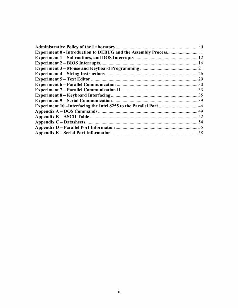
Administrative Policy of the Laboratory ....................................................................... iii Experiment 0 - Introduction to DEBUG and the Assembly Process............................ 1 Experiment 1 – Subroutines, and DOS Interrupts ...................................................... 12 Experiment 2 – BIOS Interrupts. .................................................................................. 16 Experiment 3 – Mouse and Keyboard Programming ................................................. 21 Experiment 4 – String Instructions ............................................................................... 26 Experiment 5 – Text Editor ........................................................................................... 29 Experiment 6 – Parallel Communication ..................................................................... 30 Experiment 7 – Parallel Communication II ................................................................. 33 Experiment 8 – Keyboard Interfacing .......................................................................... 35 Experiment 9 – Serial Communication......................................................................... 39 Experiment 10 –Interfacing the Intel 8255 to the Parallel Port ................................. 46 Appendix A – DOS Commands ..................................................................................... 49 Appendix B – ASCII Table ............................................................................................ 52 Appendix C – Datasheets................................................................................................ 54 Appendix D – Parallel Port Information ...................................................................... 55 Appendix E – Serial Port Information.......................................................................... 58
iii
Administrative Policy of the Laboratory
1) You are not allowed to smoke, eat or drink in the Laboratory. You are expected to conduct yourself professionally, and to keep your bench area clean and organized. You are required to return all equipment and parts used in the experiment to their proper places before you leave the lab.
2) You are expected to work in a group, which is defined to contain at most two people. If there are an odd number of people in the class section you are enrolled to, then someone will work alone. You are allowed to select your partner, but you must select a partner who does not have the same major as you, in other words, if you are an EE student you have to select an ECE student to be your partner, and if you are ECE student you must select an EE student as a partner. In the case there aren’t enough students of different majors in the same section then groups formed with student of the same majors will be allowed.
3) You are encouraged to work on your programs outside of the lab. You are also expected to build and test your circuits, which may be built in advance. It is your responsibility to demonstrate to your lab instructor that the circuits you built do what they are supposed to do!
4) Lab reports will consist of your program listing. 5) If in a particular lab session you finish your experiment, due on that date, ahead of
time, you may choose to work on any of the previous experiments you have attempted and were unable to get it to work. You will not be allowed to work on an experiment you have not worked on previously.
6) In order to be able to borrow the lab equipment you must sign the Equipment Usage Policy.
7) The tools and instruments in each lab station are not supposed to be removed from the laboratory.
8) The Instructors are available to assist you in debugging the software or troubleshoot the hardware, but it is not the Instructors’ responsibility to make your experiment work. It is therefore the responsibility of the student to complete the lab.
9) There will be a make up lab session at the end of the semester. During that session you will be allowed to make up at most two experiments you have previously worked on. Note that this is an opportunity being afforded to you so that you may work again on an experiment you previously attempted but were unsuccessful. If you did not work on an experiment during a previous lab session you will not be allowed to make it up during the make up session.
10) There will be a one-hour final practical examination, consisting of a program you are expected to write, debug, and demonstrate that it works. Every student will work alone on the final exam..
11) You may choose to request partial credit for a laboratory project you may be having difficulty in completing. Note that after a grade is assigned to a laboratory project that grade will not be changed, in other words, you forfeit being able to make that project up.
1
Experiment 0 - Introduction to DEBUG and the Assembly Process This experiment will introduce you to DEBUG and TASM, allowing you to become familiar with the process of assembling, debugging and executing an assembly language program with a PC. DEBUG is a program available with every version of WINDOWS and DOS. Here you will learn how to use DEBUG to assemble, disassemble, execute and debug assembly language programs with a PC. You will also be instructed on how to examine and modify the memory and CPU registers of your PC. TASM (Turbo Assembler) is the assembler you will use in the lab this semester. One may find many assemblers like: MASM, NASN, TASM, etc, on the web. I recommend you download one to your computer at home so that you may work on your project away from the lab. In this experiment you will copy, edit, assemble, link, debug and execute the program. During this process you will be using several programs, such as Turbo Assembler, Turbo Linker, Debug, and Notepad or Edit to accomplish your task. The knowledge acquired in this experiment will be extremely useful when working with the programs you will write during the semester. You may want to modify and save the program so that you can use it as the starting point when programming you next assignments. Do that by eliminating the red italicized statements. The following convention will be used with all examples shown in this manual: CAPITALIZED ITALICS REPRESENTS THE INFORMATION TYPED BY THE USER. CAPITALIZED BOLD REPRESENTS THE COMPUTERS RESPONSE. It is also suggested that the students use a floppy disk in drive A: or a pen drive to store their programs. This will avoid the possibility of having your programs copied in case you forget to erase them from drive C:. Check appendix A for some very useful DOS commands you may need to know. Write the answers to the questions in this experiment on the space provided, and then hand the answer sheet to the Instructor before leaving the lab. Loading DEBUG 1 – Open a DOS window by double clicking the DOS WINDOW icon on the desktop or in the Programs Menu. 2 – Issue the following command at the DOS prompt to load DEBUG: A:\DEBUG <ENTER> What prompt is displayed? _____________ Exiting DEBUG
2
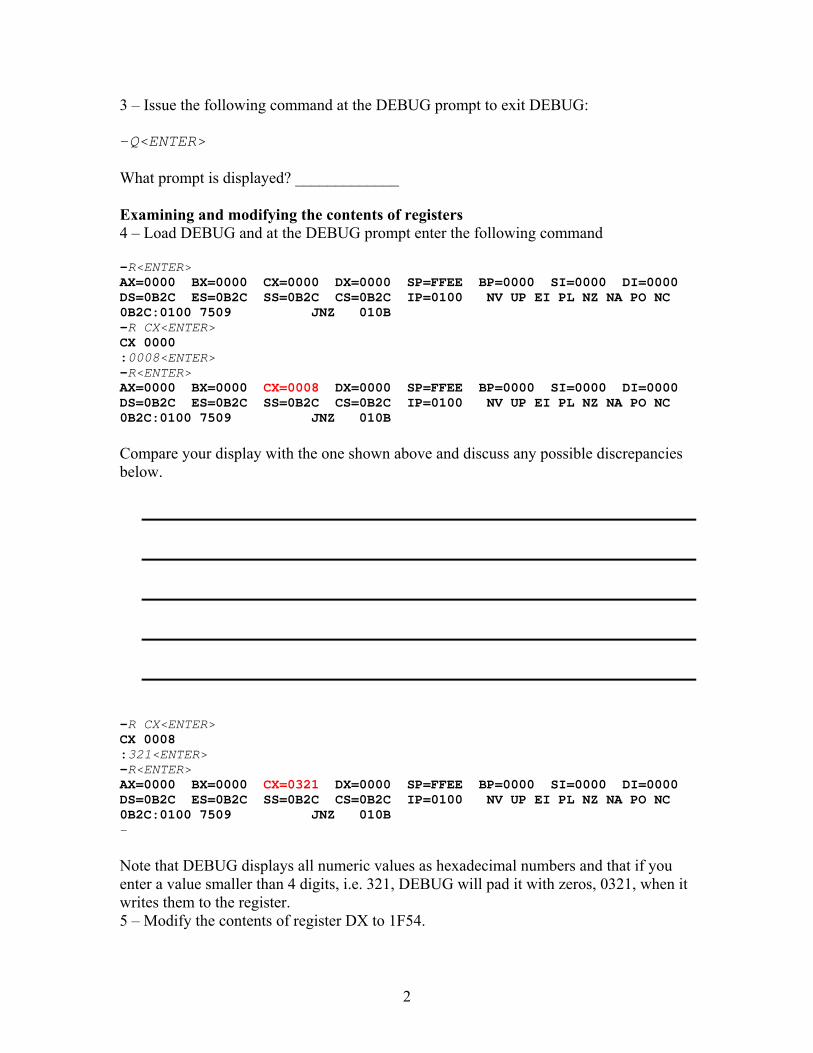
3 – Issue the following command at the DEBUG prompt to exit DEBUG: -Q<ENTER> What prompt is displayed? _____________ Examining and modifying the contents of registers 4 – Load DEBUG and at the DEBUG prompt enter the following command -R<ENTER> AX=0000 BX=0000 CX=0000 DX=0000 SP=FFEE BP=0000 SI=0000 DI=0000 DS=0B2C ES=0B2C SS=0B2C CS=0B2C IP=0100 NV UP EI PL NZ NA PO NC 0B2C:0100 7509 JNZ 010B -R CX<ENTER> CX 0000 :0008<ENTER> -R<ENTER> AX=0000 BX=0000 CX=0008 DX=0000 SP=FFEE BP=0000 SI=0000 DI=0000 DS=0B2C ES=0B2C SS=0B2C CS=0B2C IP=0100 NV UP EI PL NZ NA PO NC 0B2C:0100 7509 JNZ 010B Compare your display with the one shown above and discuss any possible discrepancies below.
-R CX<ENTER> CX 0008 :321<ENTER> -R<ENTER> AX=0000 BX=0000 CX=0321 DX=0000 SP=FFEE BP=0000 SI=0000 DI=0000 DS=0B2C ES=0B2C SS=0B2C CS=0B2C IP=0100 NV UP EI PL NZ NA PO NC 0B2C:0100 7509 JNZ 010B - Note that DEBUG displays all numeric values as hexadecimal numbers and that if you enter a value smaller than 4 digits, i.e. 321, DEBUG will pad it with zeros, 0321, when it writes them to the register. 5 – Modify the contents of register DX to 1F54.
3
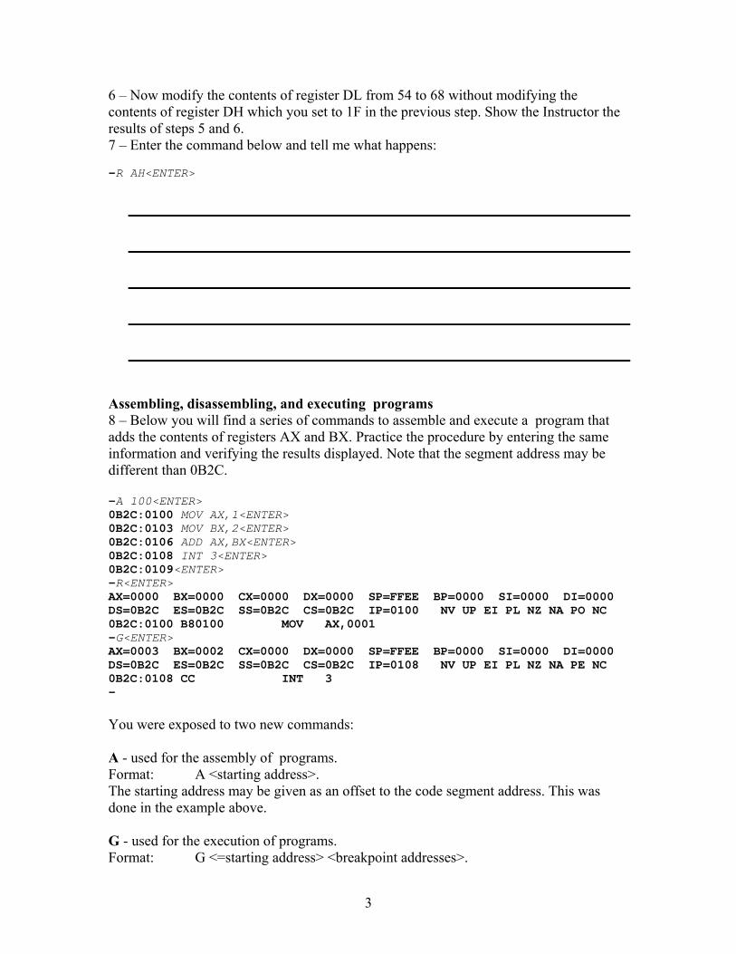
6 – Now modify the contents of register DL from 54 to 68 without modifying the contents of register DH which you set to 1F in the previous step. Show the Instructor the results of steps 5 and 6. 7 – Enter the command below and tell me what happens: -R AH<ENTER>
Assembling, disassembling, and executing programs 8 – Below you will find a series of commands to assemble and execute a program that adds the contents of registers AX and BX. Practice the procedure by entering the same information and verifying the results displayed. Note that the segment address may be different than 0B2C. -A 100<ENTER> 0B2C:0100 MOV AX,1<ENTER> 0B2C:0103 MOV BX,2<ENTER> 0B2C:0106 ADD AX,BX<ENTER> 0B2C:0108 INT 3<ENTER> 0B2C:0109<ENTER> -R<ENTER> AX=0000 BX=0000 CX=0000 DX=0000 SP=FFEE BP=0000 SI=0000 DI=0000 DS=0B2C ES=0B2C SS=0B2C CS=0B2C IP=0100 NV UP EI PL NZ NA PO NC 0B2C:0100 B80100 MOV AX,0001 -G<ENTER> AX=0003 BX=0002 CX=0000 DX=0000 SP=FFEE BP=0000 SI=0000 DI=0000 DS=0B2C ES=0B2C SS=0B2C CS=0B2C IP=0108 NV UP EI PL NZ NA PE NC 0B2C:0108 CC INT 3 - You were exposed to two new commands: A - used for the assembly of programs. Format: A <starting address>. The starting address may be given as an offset to the code segment address. This was done in the example above. G - used for the execution of programs. Format: G <=starting address> <breakpoint addresses>.
4
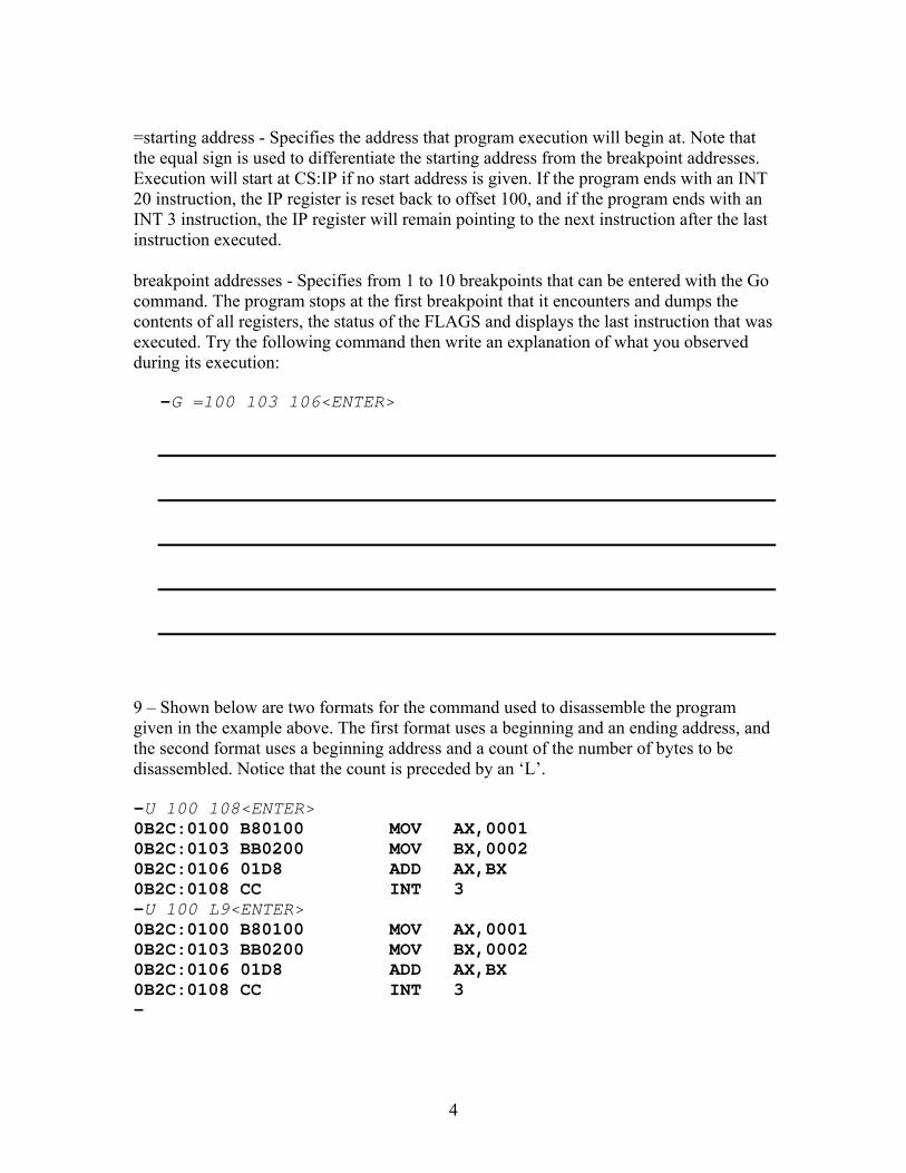
=starting address - Specifies the address that program execution will begin at. Note that the equal sign is used to differentiate the starting address from the breakpoint addresses. Execution will start at CS:IP if no start address is given. If the program ends with an INT 20 instruction, the IP register is reset back to offset 100, and if the program ends with an INT 3 instruction, the IP register will remain pointing to the next instruction after the last instruction executed. breakpoint addresses - Specifies from 1 to 10 breakpoints that can be entered with the Go command. The program stops at the first breakpoint that it encounters and dumps the contents of all registers, the status of the FLAGS and displays the last instruction that was executed. Try the following command then write an explanation of what you observed during its execution:
-G =100 103 106<ENTER>
9 – Shown below are two formats for the command used to disassemble the program given in the example above. The first format uses a beginning and an ending address, and the second format uses a beginning address and a count of the number of bytes to be disassembled. Notice that the count is preceded by an ‘L’. -U 100 108<ENTER> 0B2C:0100 B80100 MOV AX,0001 0B2C:0103 BB0200 MOV BX,0002 0B2C:0106 01D8 ADD AX,BX 0B2C:0108 CC INT 3 -U 100 L9<ENTER> 0B2C:0100 B80100 MOV AX,0001 0B2C:0103 BB0200 MOV BX,0002 0B2C:0106 01D8 ADD AX,BX 0B2C:0108 CC INT 3 -
5
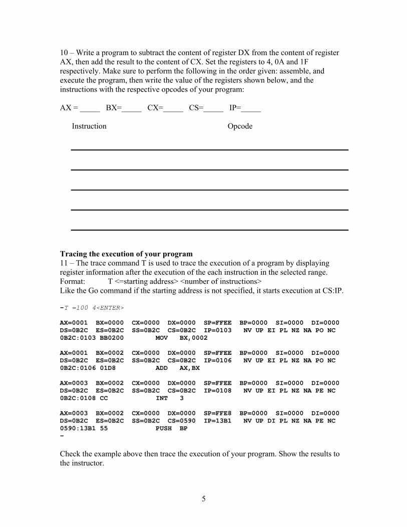
10 – Write a program to subtract the content of register DX from the content of register AX, then add the result to the content of CX. Set the registers to 4, 0A and 1F respectively. Make sure to perform the following in the order given: assemble, and execute the program, then write the value of the registers shown below, and the instructions with the respective opcodes of your program: AX = _____ BX=_____ CX=_____ CS=_____ IP=_____
Instruction Opcode
Tracing the execution of your program 11 – The trace command T is used to trace the execution of a program by displaying register information after the execution of the each instruction in the selected range. Format: T <=starting address> <number of instructions> Like the Go command if the starting address is not specified, it starts execution at CS:IP. -T =100 4<ENTER> AX=0001 BX=0000 CX=0000 DX=0000 SP=FFEE BP=0000 SI=0000 DI=0000 DS=0B2C ES=0B2C SS=0B2C CS=0B2C IP=0103 NV UP EI PL NZ NA PO NC 0B2C:0103 BB0200 MOV BX,0002 AX=0001 BX=0002 CX=0000 DX=0000 SP=FFEE BP=0000 SI=0000 DI=0000 DS=0B2C ES=0B2C SS=0B2C CS=0B2C IP=0106 NV UP EI PL NZ NA PO NC 0B2C:0106 01D8 ADD AX,BX AX=0003 BX=0002 CX=0000 DX=0000 SP=FFEE BP=0000 SI=0000 DI=0000 DS=0B2C ES=0B2C SS=0B2C CS=0B2C IP=0108 NV UP EI PL NZ NA PE NC 0B2C:0108 CC INT 3 AX=0003 BX=0002 CX=0000 DX=0000 SP=FFE8 BP=0000 SI=0000 DI=0000 DS=0B2C ES=0B2C SS=0B2C CS=0590 IP=13B1 NV UP DI PL NZ NA PE NC 0590:13B1 55 PUSH BP - Check the example above then trace the execution of your program. Show the results to the instructor.
6
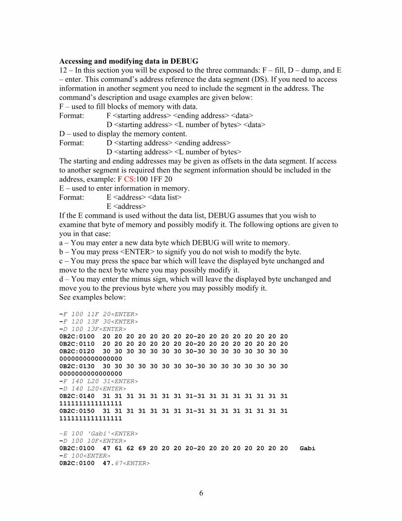
Accessing and modifying data in DEBUG 12 – In this section you will be exposed to the three commands: F – fill, D – dump, and E – enter. This command’s address reference the data segment (DS). If you need to access information in another segment you need to include the segment in the address. The command’s description and usage examples are given below: F – used to fill blocks of memory with data. Format: F <starting address> <ending address> <data> D <starting address> <L number of bytes> <data> D – used to display the memory content. Format: D <starting address> <ending address> D <starting address> <L number of bytes> The starting and ending addresses may be given as offsets in the data segment. If access to another segment is required then the segment information should be included in the address, example: F CS:100 1FF 20 E – used to enter information in memory. Format: E <address> <data list> E <address> If the E command is used without the data list, DEBUG assumes that you wish to examine that byte of memory and possibly modify it. The following options are given to you in that case: a – You may enter a new data byte which DEBUG will write to memory. b – You may press <ENTER> to signify you do not wish to modify the byte. c – You may press the space bar which will leave the displayed byte unchanged and move to the next byte where you may possibly modify it. d – You may enter the minus sign, which will leave the displayed byte unchanged and move you to the previous byte where you may possibly modify it. See examples below: -F 100 11F 20<ENTER> -F 120 13F 30<ENTER> -D 100 13F<ENTER> 0B2C:0100 20 20 20 20 20 20 20 20-20 20 20 20 20 20 20 20 0B2C:0110 20 20 20 20 20 20 20 20-20 20 20 20 20 20 20 20 0B2C:0120 30 30 30 30 30 30 30 30-30 30 30 30 30 30 30 30 0000000000000000 0B2C:0130 30 30 30 30 30 30 30 30-30 30 30 30 30 30 30 30 0000000000000000 -F 140 L20 31<ENTER> -D 140 L20<ENTER> 0B2C:0140 31 31 31 31 31 31 31 31-31 31 31 31 31 31 31 31 1111111111111111 0B2C:0150 31 31 31 31 31 31 31 31-31 31 31 31 31 31 31 31 1111111111111111 -E 100 'Gabi'<ENTER> -D 100 10F<ENTER> 0B2C:0100 47 61 62 69 20 20 20 20-20 20 20 20 20 20 20 20 Gabi -E 100<ENTER> 0B2C:0100 47.67<ENTER>
7
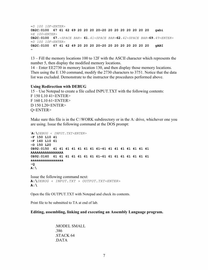
-D 100 10F<ENTER> 0B2C:0100 67 61 62 69 20 20 20 20-20 20 20 20 20 20 20 20 gabi -E 100<ENTER> 0B2C:0100 67.<SPACE BAR> 61.41<SPACE BAR>62.42<SPACE BAR>69.49<ENTER> -D 100 10F<ENTER> 0B2C:0100 67 41 42 49 20 20 20 20-20 20 20 20 20 20 20 20 gABI - 13 – Fill the memory locations 100 to 12F with the ASCII character which represents the number 5, then display the modified memory locations. 14 – Enter EE2730 in memory location 130, and then display those memory locations. Then using the E 130 command, modify the 2730 characters to 3751. Notice that the data list was excluded. Demonstrate to the instructor the procedures performed above. Using Redirection with DEBUG 15 – Use Notepad to create a file called INPUT.TXT with the following contents: F 150 L10 41<ENTER> F 160 L10 61<ENTER> D 150 L20<ENTER> Q<ENTER> Make sure this file is in the C:\WORK subdirectory or in the A: drive, whichever one you are using. Issue the following command at the DOS prompt: \A:\DEBUG < INPUT.TXT<ENTER> -F 150 L10 41 -F 160 L10 61 -D 150 L20 0B92:0150 41 41 41 41 41 41 41 41-41 41 41 41 41 41 41 41 AAAAAAAAAAAAAAAA 0B92:0160 61 61 61 61 61 61 61 61-61 61 61 61 61 61 61 61 aaaaaaaaaaaaaaaa -Q A:\ Issue the following command next: A:\DEBUG < INPUT.TXT > OUTPUT.TXT<ENTER> A:\ Open the file OUTPUT.TXT with Notepad and check its contents. Print file to be submitted to TA at end of lab. Editing, assembling, linking and executing an Assembly Language program.
.MODEL SMALL
.386
.STACK 64
.DATA
8
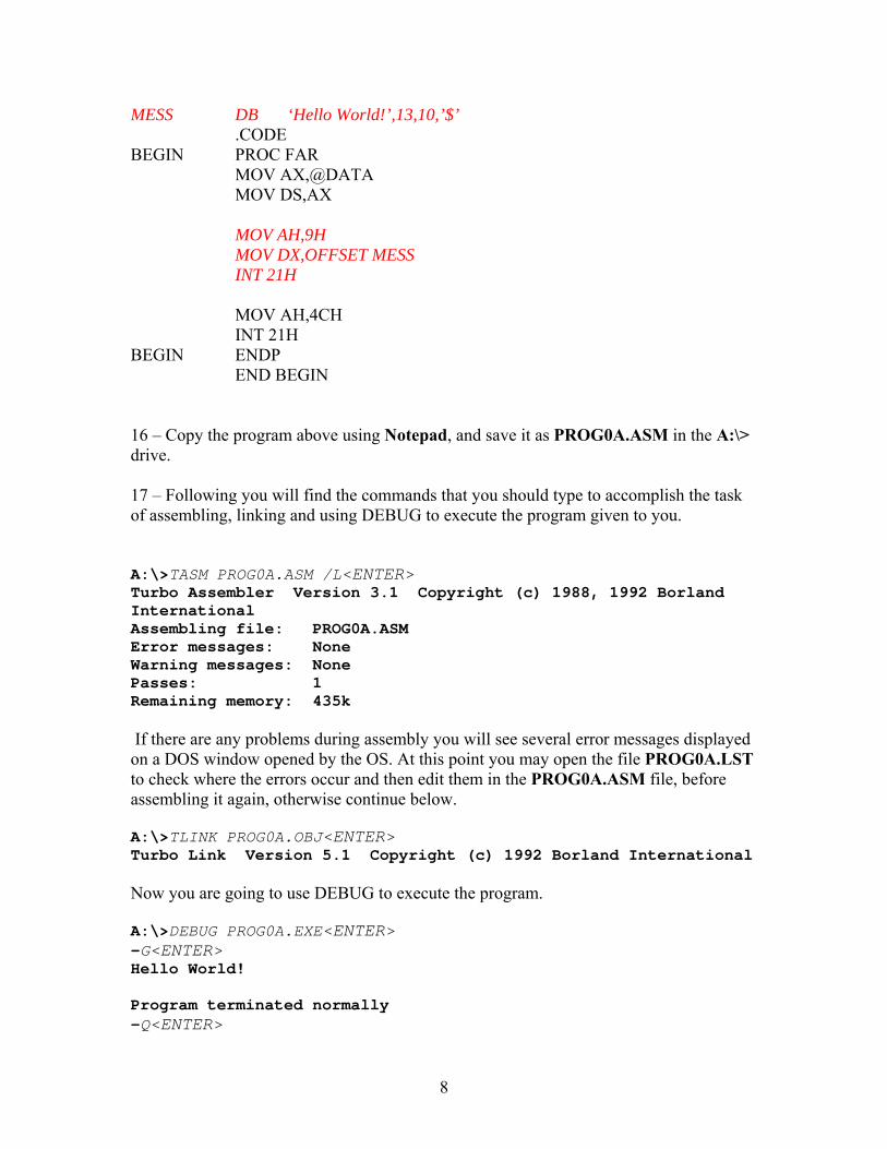
MESS DB ‘Hello World!’,13,10,’$’ .CODE BEGIN PROC FAR MOV AX,@DATA MOV DS,AX MOV AH,9H MOV DX,OFFSET MESS INT 21H MOV AH,4CH INT 21H BEGIN ENDP END BEGIN 16 – Copy the program above using Notepad, and save it as PROG0A.ASM in the A:\> drive. 17 – Following you will find the commands that you should type to accomplish the task of assembling, linking and using DEBUG to execute the program given to you. A:\>TASM PROG0A.ASM /L<ENTER> Turbo Assembler Version 3.1 Copyright (c) 1988, 1992 Borland International Assembling file: PROG0A.ASM Error messages: None Warning messages: None Passes: 1 Remaining memory: 435k
If there are any problems during assembly you will see several error messages displayed on a DOS window opened by the OS. At this point you may open the file PROG0A.LST to check where the errors occur and then edit them in the PROG0A.ASM file, before assembling it again, otherwise continue below. A:\>TLINK PROG0A.OBJ<ENTER> Turbo Link Version 5.1 Copyright (c) 1992 Borland International
Now you are going to use DEBUG to execute the program. A:\>DEBUG PROG0A.EXE<ENTER> -G<ENTER> Hello World! Program terminated normally -Q<ENTER>
9
A:\> You can also execute the program directly by doing what is shown below: A:\>PROG0A.EXE<ENTER> Hello World! A:\> 18 – Copy the program below using Notepad, and save it as PROG0B.ASM in the A:\> drive.
.MODEL SMALL
.386
.STACK 64
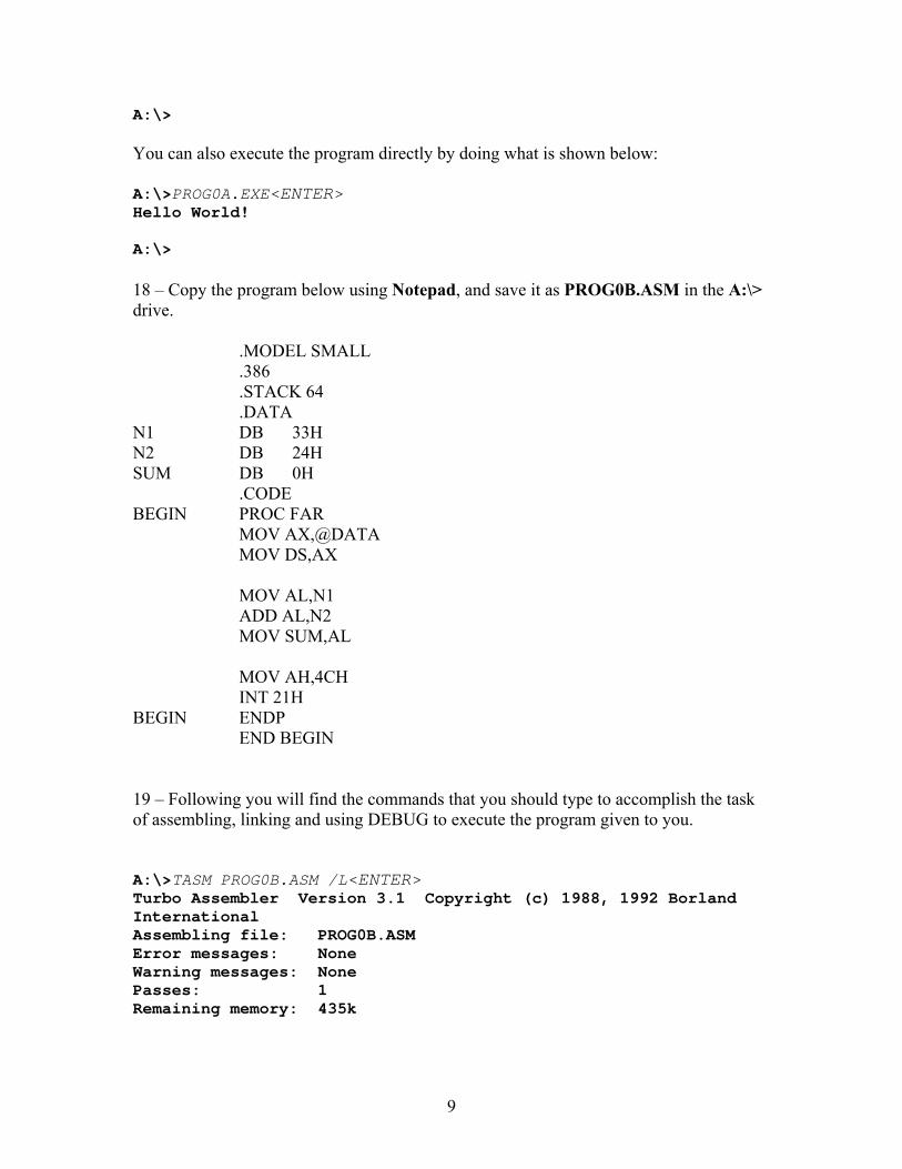
.DATA N1 DB 33H N2 DB 24H SUM DB 0H .CODE BEGIN PROC FAR MOV AX,@DATA MOV DS,AX MOV AL,N1 ADD AL,N2 MOV SUM,AL MOV AH,4CH INT 21H BEGIN ENDP END BEGIN 19 – Following you will find the commands that you should type to accomplish the task of assembling, linking and using DEBUG to execute the program given to you. A:\>TASM PROG0B.ASM /L<ENTER> Turbo Assembler Version 3.1 Copyright (c) 1988, 1992 Borland International Assembling file: PROG0B.ASM Error messages: None Warning messages: None Passes: 1 Remaining memory: 435k
10
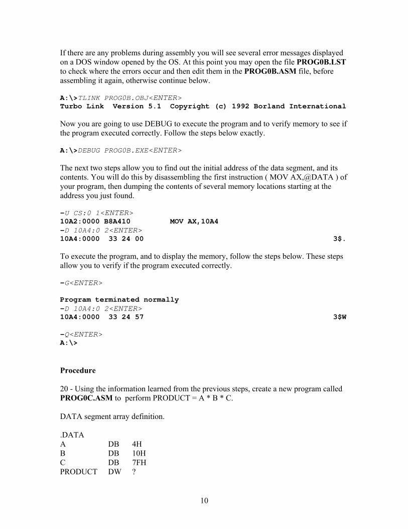
If there are any problems during assembly you will see several error messages displayed on a DOS window opened by the OS. At this point you may open the file PROG0B.LST to check where the errors occur and then edit them in the PROG0B.ASM file, before assembling it again, otherwise continue below. A:\>TLINK PROG0B.OBJ<ENTER> Turbo Link Version 5.1 Copyright (c) 1992 Borland International
Now you are going to use DEBUG to execute the program and to verify memory to see if the program executed correctly. Follow the steps below exactly. A:\>DEBUG PROG0B.EXE<ENTER> The next two steps allow you to find out the initial address of the data segment, and its contents. You will do this by disassembling the first instruction ( MOV AX,@DATA ) of your program, then dumping the contents of several memory locations starting at the address you just found. -U CS:0 1<ENTER> 10A2:0000 B8A410 MOV AX,10A4 -D 10A4:0 2<ENTER> 10A4:0000 33 24 00 3$. To execute the program, and to display the memory, follow the steps below. These steps allow you to verify if the program executed correctly. -G<ENTER> Program terminated normally -D 10A4:0 2<ENTER> 10A4:0000 33 24 57 3$W -Q<ENTER> A:\> Procedure 20 - Using the information learned from the previous steps, create a new program called PROG0C.ASM to perform PRODUCT = A * B * C. DATA segment array definition. .DATA A DB 4H B DB 10H C DB 7FH PRODUCT DW ?

11
Dump the memory where the data segment is located at and check the result of the multiplication you just performed. Show the instructor the results and hand him your observations made during the lab.
12
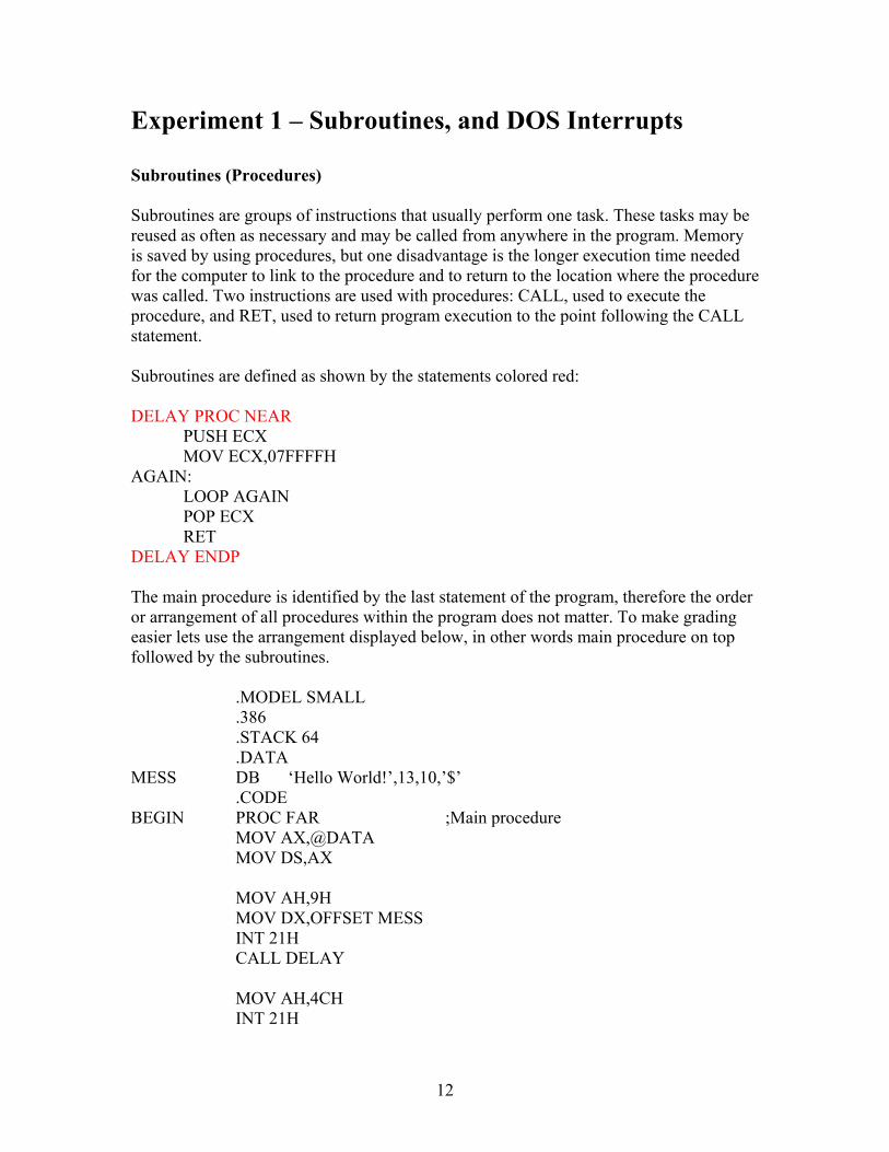
Experiment 1 – Subroutines, and DOS Interrupts Subroutines (Procedures) Subroutines are groups of instructions that usually perform one task. These tasks may be reused as often as necessary and may be called from anywhere in the program. Memory is saved by using procedures, but one disadvantage is the longer execution time needed for the computer to link to the procedure and to return to the location where the procedure was called. Two instructions are used with procedures: CALL, used to execute the procedure, and RET, used to return program execution to the point following the CALL statement. Subroutines are defined as shown by the statements colored red: DELAY PROC NEAR PUSH ECX MOV ECX,07FFFFH AGAIN: LOOP AGAIN POP ECX RET DELAY ENDP The main procedure is identified by the last statement of the program, therefore the order or arrangement of all procedures within the program does not matter. To make grading easier lets use the arrangement displayed below, in other words main procedure on top followed by the subroutines.
.MODEL SMALL
.386
.STACK 64
.DATA MESS DB ‘Hello World!’,13,10,’$’ .CODE BEGIN PROC FAR ;Main procedure MOV AX,@DATA MOV DS,AX MOV AH,9H MOV DX,OFFSET MESS INT 21H CALL DELAY MOV AH,4CH INT 21H
13
BEGIN ENDP DELAY PROC NEAR ;Subroutines PUSH ECX MOV ECX,07FFFFH AGAIN: LOOP AGAIN POP ECX RET DELAY ENDP END BEGIN DOS INT 21H INT 21H is provided by DOS, and it is stored in DRAM when the operating system is loaded. The user can invoke this interrupt to perform several useful functions, like inputting data from keyboard, and outputting data to monitor. These interrupt subroutines may be used by issuing a software interrupt call ( INT type ). The user will have to identify which function is being used by setting the AH register to a specific value. Other registers may also need to be modified. Following are the descriptions of several of the most common INT 21H functions. INT 21H Function 01H: Inputting a single character from the keyboard with echo. AH = 01H AL = inputted ASCII character code Code example to input a single character from keyboard and to echo it to the display. MOV AH,01H INT 21H INT 21H Function 02H: Outputting a single character to the monitor. AH = 02H DL = ASCII character code to be displayed INT 21H Function 09H: Outputting a string terminated with $ to the monitor. AH = 09H DX = String address
14
INT 21H Function 4CH: Terminate a process ( EXIT ). AH = 4CH AL = binary return code This interrupt terminates a process and returns control to DOS or the parent process. Procedure Write a program to generate the first five numbers of the geometric series given below, and display them to the PC monitor in decimal.
( ) n
nnA 23
5
1∑=
×=
1 – Calculate series value and store it in the SERIES array. 2 – Convert values in SERIES array to decimal. 3 – Convert decimal value to ASCII, store them in DEC array and display them to monitor. The monitor display should have the following format: Geometric series(1) = 6 Geometric series(2) = 18 Geometric series(3) = 42 Geometric series(4) = 90 Geometric series(5) = 186 The program should have the following 3 subroutines: GEN_SER: to generate Geometric series(X) where: 1 ≤ X ≤ 5;
- Use register AL to pass the X value to the subroutine; - Use register BX to pass the number of the element of the array
SERIES where result of Geometric series(X) will be stored at; ASCII_DEC: to convert an 8 bit binary number valued between 00000000B and 11111111B to a three digits decimal number represented by three ASCII numbers valued ‘0’, ‘1’, ‘2’, ‘3’, ‘4’, ‘5’, ‘6’, ‘7’, ‘8’, ‘9’;
- Use register AL to pass number to be converted to hexadecimal to subroutine;
- Use register BX to pass the number of the element of the array DEC where the two hexadecimal digits will be stored at;
DISPLAY_LINE: to display a line of data to the monitor. The format of the line was given above.
15
- Use register BX to pass the element of the array DEC containing the decimal digits to be displayed.
Array definitions: SERIES DB 5 DUP(?) DEC DB 20 DUP(?) Store the information into the DEC array MSD first, and LSD last. Example: Assuming Geometric series(1) = 6, and Geometric series(2) = 18, then the values would be stored in the DEC array as shown below. DEC(0)=’0’ DEC (1)=’0’ DEC (2)=’6’ DEC (3)=’$’ DEC (4)=’0’ DEC (5)=’1’ DEC (6)=’8’ DEC (7)=’$’ Note that the three decimal digits are followed by a dollar sign. This will simplify the display of the data to the monitor. Dump the data segment to a file and include the results with your program.
16
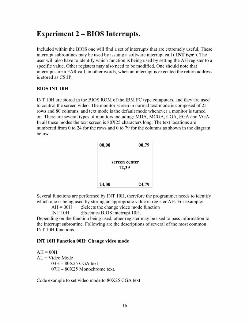
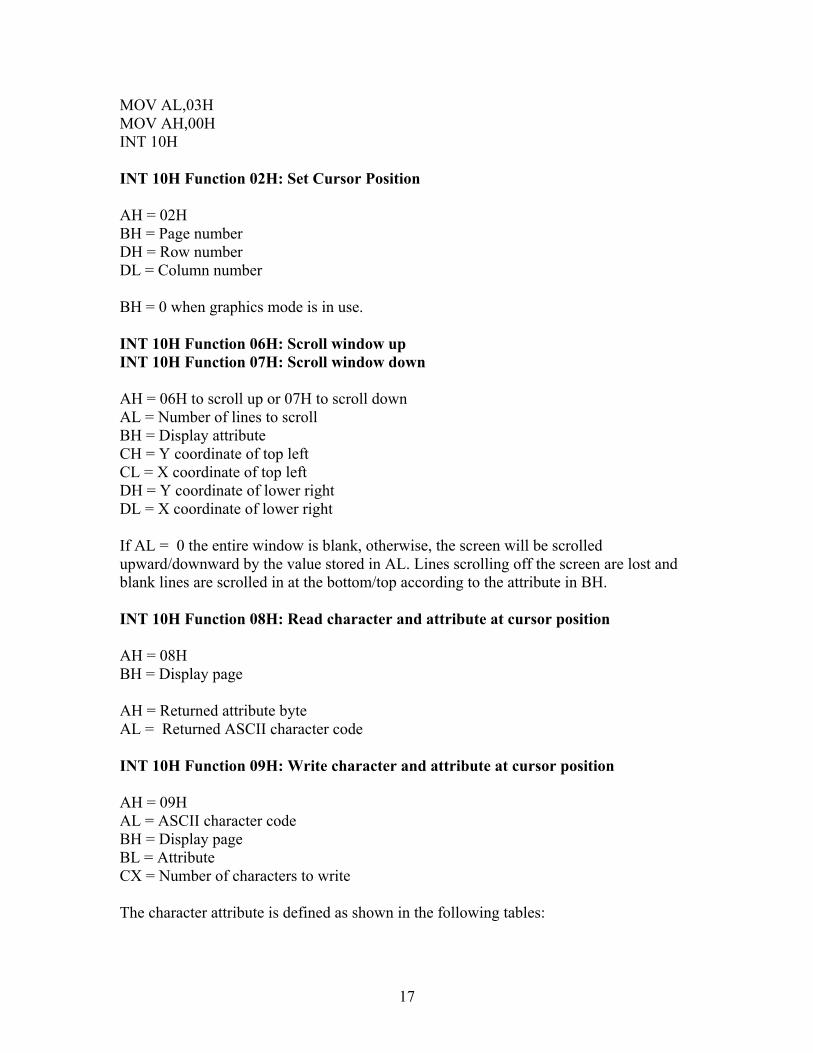
Experiment 2 – BIOS Interrupts. Included within the BIOS one will find a set of interrupts that are extremely useful. These interrupt subroutines may be used by issuing a software interrupt call ( INT type ). The user will also have to identify which function is being used by setting the AH register to a specific value. Other registers may also need to be modified. One should note that interrupts are a FAR call, in other words, when an interrupt is executed the return address is stored as CS:IP. BIOS INT 10H INT 10H are stored in the BIOS ROM of the IBM PC type computers, and they are used to control the screen video. The monitor screen in normal text mode is composed of 25 rows and 80 columns, and text mode is the default mode whenever a monitor is turned on. There are several types of monitors including: MDA, MCGA, CGA, EGA and VGA. In all these modes the text screen is 80X25 characters long. The text locations are numbered from 0 to 24 for the rows and 0 to 79 for the columns as shown in the diagram below.
00,00 00,79 screen center 12,39 24,00 24,79
Several functions are performed by INT 10H, therefore the programmer needs to identify which one is being used by storing an appropriate value in register AH. For example: AH = 00H ;Selects the change video mode function INT 10H ;Executes BIOS interrupt 10H. Depending on the function being used, other register may be used to pass information to the interrupt subroutine. Following are the descriptions of several of the most common INT 10H functions. INT 10H Function 00H: Change video mode AH = 00H AL = Video Mode 03H – 80X25 CGA text 07H – 80X25 Monochrome text. Code example to set video mode to 80X25 CGA text
17
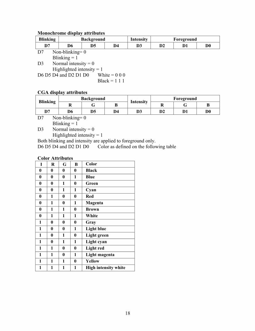
MOV AL,03H MOV AH,00H INT 10H INT 10H Function 02H: Set Cursor Position AH = 02H BH = Page number DH = Row number DL = Column number BH = 0 when graphics mode is in use. INT 10H Function 06H: Scroll window up INT 10H Function 07H: Scroll window down AH = 06H to scroll up or 07H to scroll down AL = Number of lines to scroll BH = Display attribute CH = Y coordinate of top left CL = X coordinate of top left DH = Y coordinate of lower right DL = X coordinate of lower right If AL = 0 the entire window is blank, otherwise, the screen will be scrolled upward/downward by the value stored in AL. Lines scrolling off the screen are lost and blank lines are scrolled in at the bottom/top according to the attribute in BH. INT 10H Function 08H: Read character and attribute at cursor position AH = 08H BH = Display page AH = Returned attribute byte AL = Returned ASCII character code INT 10H Function 09H: Write character and attribute at cursor position AH = 09H AL = ASCII character code BH = Display page BL = Attribute CX = Number of characters to write The character attribute is defined as shown in the following tables:
18
Monochrome display attributes Blinking Background Intensity Foreground
D7 D6 D5 D4 D3 D2 D1 D0 D7 Non-blinking= 0 Blinking = 1 D3 Normal intensity = 0 Highlighted intensity = 1 D6 D5 D4 and D2 D1 D0 White = 0 0 0 Black = 1 1 1 CGA display attributes
Background Foreground Blinking
R G B Intensity
R G B D7 D6 D5 D4 D3 D2 D1 D0
D7 Non-blinking= 0 Blinking = 1 D3 Normal intensity = 0 Highlighted intensity = 1 Both blinking and intensity are applied to foreground only. D6 D5 D4 and D2 D1 D0 Color as defined on the following table Color Attributes
I R G B Color 0 0 0 0 Black 0 0 0 1 Blue 0 0 1 0 Green 0 0 1 1 Cyan 0 1 0 0 Red 0 1 0 1 Magenta 0 1 1 0 Brown 0 1 1 1 White 1 0 0 0 Gray 1 0 0 1 Light blue 1 0 1 0 Light green 1 0 1 1 Light cyan 1 1 0 0 Light red 1 1 0 1 Light magenta 1 1 1 0 Yellow 1 1 1 1 High intensity white
19
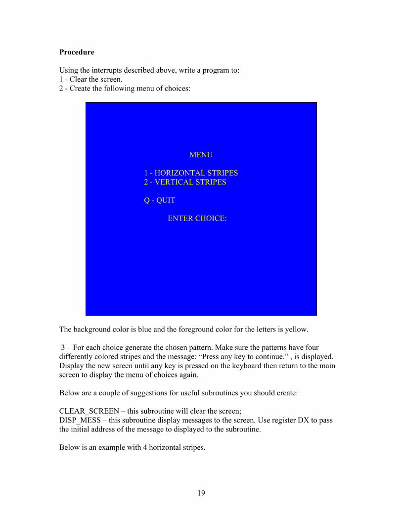
Procedure Using the interrupts described above, write a program to: 1 - Clear the screen. 2 - Create the following menu of choices:
The background color is blue and the foreground color for the letters is yellow. 3 – For each choice generate the chosen pattern. Make sure the patterns have four differently colored stripes and the message: “Press any key to continue.” , is displayed. Display the new screen until any key is pressed on the keyboard then return to the main screen to display the menu of choices again. Below are a couple of suggestions for useful subroutines you should create: CLEAR_SCREEN – this subroutine will clear the screen; DISP_MESS – this subroutine display messages to the screen. Use register DX to pass the initial address of the message to displayed to the subroutine. Below is an example with 4 horizontal stripes.
MENU 1 - HORIZONTAL STRIPES 2 - VERTICAL STRIPES Q - QUIT ENTER CHOICE:

20
Press any key to continue
21
Experiment 3 – Mouse and Keyboard Programming In this experiment you are going to be exposed to both mouse and keyboard programming. Keyboard programming will be discussed first, and this entails, a discussion of the programming interface to the keyboard of your PC. Like the previous BIOS and DOS interrupts, keyboard programming is achieved by the use of BIOS Interrupt 16H explained below. Interrupt 16H Option 0H: Keyboard Read. Result registers:
• AH – Key scan code. • AL – ASCII character.
Note: Reads and removes one character from the keyboard buffer. If there isn’t one it waits until there is. Interrupt 16H Option 1H: Get keyboard status. Result registers and flags:
• ZF = 1 if no key is waiting. • ZF = 0 if key is waiting:
o AH – Key scan code. o AL – ASCII character.
Note: Checks to see if there is a key waiting in the keyboard buffer. If a key press is waiting in the keyboard buffer, then ZF=0, and the codes are returned in AH and AL respectively. This function works like function 0 except the character is not removed from the keyboard buffer. Interrupt 16H Option 2H: Get keyboard status bytes. Result registers and flags:
• AL – ASCII character. o D0 – Right Shift pressed; o D1 Left shift pressed; o D2 – Ctrl pressed; o D3 – Alt pressed; o D4 – Scroll Lock state toggled; o D5 – NumLock state toggled; o D6 – CapsLock state toggled; o D7 – Insert toggled.
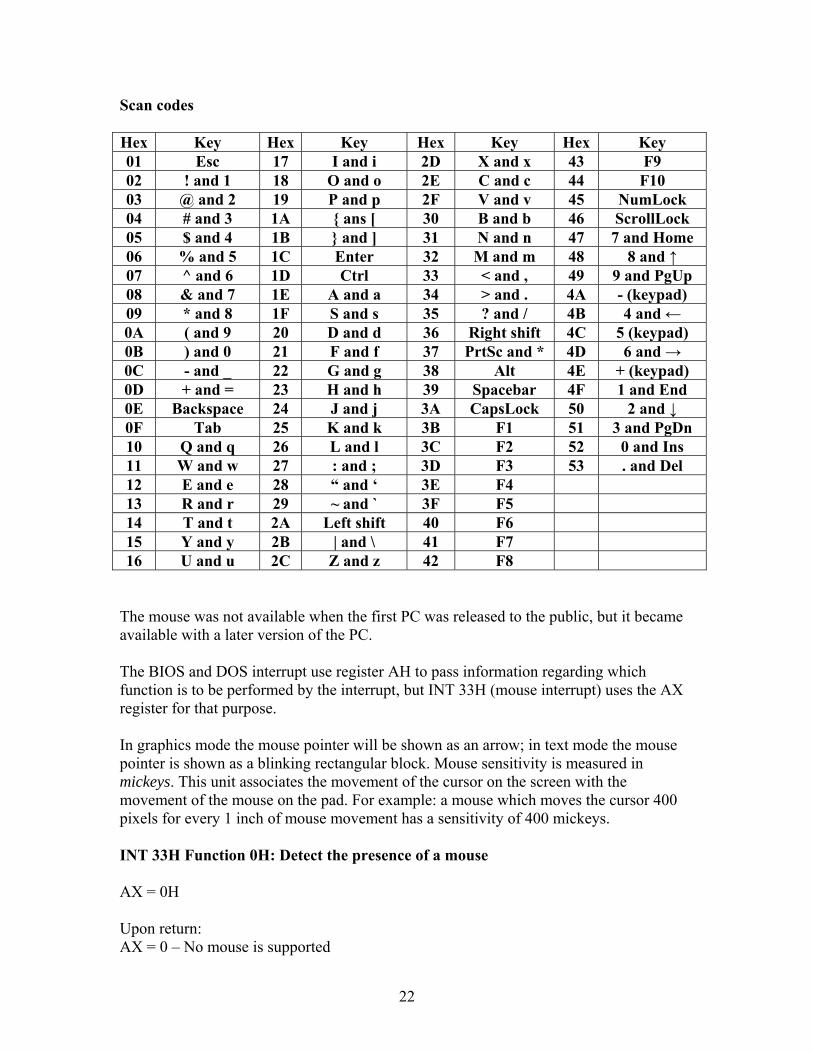
The table of scan codes is given below. Notice that many keys that do not have an ASCII equivalent may be programmed using scan codes. Some examples: F1, F2, PgDn, NumLock, etc.
22
Scan codes Hex Key Hex Key Hex Key Hex Key 01 Esc 17 I and i 2D X and x 43 F9 02 ! and 1 18 O and o 2E C and c 44 F10 03 @ and 2 19 P and p 2F V and v 45 NumLock 04 # and 3 1A { ans [ 30 B and b 46 ScrollLock 05 $ and 4 1B } and ] 31 N and n 47 7 and Home 06 % and 5 1C Enter 32 M and m 48 8 and ↑ 07 ^ and 6 1D Ctrl 33 < and , 49 9 and PgUp 08 & and 7 1E A and a 34 > and . 4A - (keypad) 09 * and 8 1F S and s 35 ? and / 4B 4 and ← 0A ( and 9 20 D and d 36 Right shift 4C 5 (keypad) 0B ) and 0 21 F and f 37 PrtSc and * 4D 6 and → 0C - and _ 22 G and g 38 Alt 4E + (keypad) 0D + and = 23 H and h 39 Spacebar 4F 1 and End 0E Backspace 24 J and j 3A CapsLock 50 2 and ↓ 0F Tab 25 K and k 3B F1 51 3 and PgDn 10 Q and q 26 L and l 3C F2 52 0 and Ins 11 W and w 27 : and ; 3D F3 53 . and Del 12 E and e 28 “ and ‘ 3E F4 13 R and r 29 ~ and ` 3F F5 14 T and t 2A Left shift 40 F6 15 Y and y 2B | and \ 41 F7 16 U and u 2C Z and z 42 F8
The mouse was not available when the first PC was released to the public, but it became available with a later version of the PC. The BIOS and DOS interrupt use register AH to pass information regarding which function is to be performed by the interrupt, but INT 33H (mouse interrupt) uses the AX register for that purpose. In graphics mode the mouse pointer will be shown as an arrow; in text mode the mouse pointer is shown as a blinking rectangular block. Mouse sensitivity is measured in mickeys. This unit associates the movement of the cursor on the screen with the movement of the mouse on the pad. For example: a mouse which moves the cursor 400 pixels for every 1 inch of mouse movement has a sensitivity of 400 mickeys. INT 33H Function 0H: Detect the presence of a mouse AX = 0H Upon return: AX = 0 – No mouse is supported
23
AX > 0 – Mouse is supported Example: MOV AX,0 INT 33H CMP AX,0 JE Exit … … INT 33H Function 1H: Displays the mouse cursor AX = 1H INT 33H Function 2H: Hides the mouse cursor AX = 2H INT 33H Function 3H: Gets current mouse cursor position AX = 3H Upon return: CX = Horizontal coordinate in pixels. DX = Vertical coordinate in pixels. In text mode, one needs to divide these coordinates by 8 to get the character location. This is due to the fact that each character is made with an 8X8 pixel matrix. INT 33H Function 4H: Sets current mouse cursor position AX = 4H CX = Horizontal coordinate in pixels. DX = Vertical coordinate in pixels. In text mode, one needs to divide these coordinates by 8 to get the character location. This is due to the fact that each character is made with an 8X8 pixel matrix. INT 33H Function 5H: Gets mouse button press information
24
AX = 5H BX = 0 for left button, 1 for right button, 2 for center button; Upon return: AX = button status, where: D0 = Left button: 1 = Down, 0 = Up; D1 = Right button: 1 = Down, 0 = Up; D2 = Center button; 1 = Down, 0 = Up BX = Button press count since the last call to this function. CX = Horizontal coordinate in pixels at the last button press. DX = Vertical coordinate in pixels at the last button press. INT 33H Function 6H: Gets mouse button release information AX = 6H BX = 0 for left button, 1 for right button, 2 for center button; Upon return: AX = button status, where: D0 = Left button: 1 = Down, 0 = Up; D1 = Right button: 1 = Down, 0 = Up; D2 = Center button; 1 = Down, 0 = Up BX = Button release count since the last call to this function. CX = Horizontal coordinate in pixels at the last button press. DX = Vertical coordinate in pixels at the last button press. INT 33H Function 7H: Sets horizontal for the mouse pointer AX = 7H CX = Minimum x coordinate in pixels. DX = Maximum x coordinate in pixels. INT 33H Function 8H: Sets horizontal for the mouse pointer AX = 8H CX = Minimum x coordinate in pixels. DX = Maximum x coordinate in pixels. INT 33H Function 10H: Sets an exclusion area for the mouse pointer
25
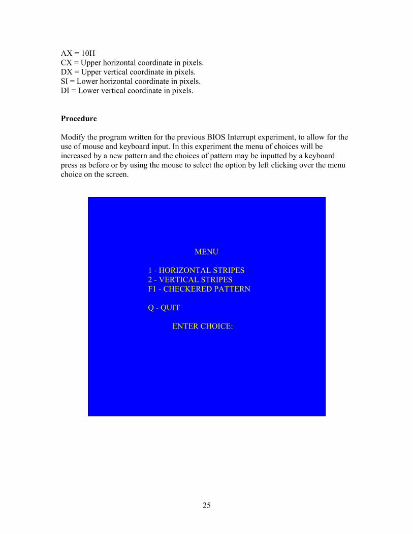
AX = 10H CX = Upper horizontal coordinate in pixels. DX = Upper vertical coordinate in pixels. SI = Lower horizontal coordinate in pixels. DI = Lower vertical coordinate in pixels. Procedure Modify the program written for the previous BIOS Interrupt experiment, to allow for the use of mouse and keyboard input. In this experiment the menu of choices will be increased by a new pattern and the choices of pattern may be inputted by a keyboard press as before or by using the mouse to select the option by left clicking over the menu choice on the screen.
MENU 1 - HORIZONTAL STRIPES 2 - VERTICAL STRIPES F1 - CHECKERED PATTERN Q - QUIT ENTER CHOICE:
26
Experiment 4 – String Instructions In this experiment, software to be used to manipulate data entered into a buffer will be developed using string instructions. These subroutines you will develop will simulate the DOS function keys F1, F3 and F5. The 386 instruction set contain a group of instructions to perform string manipulation with auto increment/decrement addressing. Two dedicated registers, DI and SI, are used for this purpose, and they are used as pointers to the data being manipulated. Note that when data is to be stored in memory the DI (Destination Index) register points, relative to the ES register, to the memory location. If data is to be read from memory, then the SI (Source Index) register points, relative to the DS register to the memory location. Some instructions may use both DI and SI registers as pointers. These register are automatically incremented or decremented depending on the value of the direction flag If the direction flag is set (DF = 1) then the registers are decremented, if the direction flag is clear ( DF = 0 ) then the registers are incremented. The direction flag may be set with the STD instruction and cleared with the CLD instruction. Below you will find a brief description of some string instructions: LODSB/LODSW/LODSD/LODS – Load string byte/word/double word. This instruction loads a value from memory into the AL, AX or EAX register. If the direction flag is clear the SI register will be incremented by 1, 2, or 4 depending on whether the instruction is operating on a byte, word or double word respectively. Otherwise, if the direction flag is set the SI register will be decremented by 1, 2, or 4 again with respect of the size of data being manipulated. AL/AX/EAX=DS:[SI];SI±1/2/4 STOSB/STOSW/STOSD/STOS – Store string byte/word/double word. This instruction stores a value from the AL, AX or EAX register into memory. If the direction flag is clear the DI register will be incremented by 1, 2, or 4 depending on whether the instruction is operating on a byte, word or double word respectively. Otherwise, if the direction flag is set the DI register will be decremented by 1, 2, or 4 again with respect of the size of data being manipulated. ES:[DI]=AL/AX/EAX;DI±1/2/4 SCASB/SCASW/SCASD/SCAS – Compares a string byte/word/double word in memory to the contents of the AL/AX/EAX registers and modifies the flags accordingly. Note that the contents of the memory and the AL/AX/EAX register are not modified, and that the memory location is pointed to by the DI register relative to the ES register. Also the DI register is automatically incremented/decremented dependent on the value of the direction flag DF=0/1 respectively. The two operands are actually compared by
27
subtracting the value of the memory location pointed to by DI from the value stored in the AL/AX/EAX register. MOVSB/MOVSW/MOVSD/MOVS – Moves a string byte/word/double word located at an address pointed to by the SI register relative to the DS register, to another address pointed to by the DI register relative to the ES register. If the direction flag is clear the SI and DI registers will be incremented by 1, 2, or 4 depending on whether the instruction is operating on a byte, word or double word respectively. Otherwise, if the direction flag is set the SI and DI registers will be decremented by 1, 2, or 4 again with respect of the size of data being manipulated. ES:[DI]=DS:[SI];SI±1/2/4;DI±1/2/4 CMPSB/CMPSW/CMPSD/CMPS – Compares a string byte/word/double word located at an address pointed to by the SI register relative to the DS register, to another string byte/word/double word located at an address pointed to by the DI register relative to the ES register and modifies the flags accordingly. Note that the contents of the memory are not modified, and that the SI and DI registers are automatically incremented/decremented dependent on the value of the direction flag DF=0/1 respectively. The two operands are actually compared by subtracting the value of the memory location pointed to by DI from the memory location pointed to by SI. REP/REPZ/REPNZ - These prefixes cause the string instruction that follows them to be repeated the number of times in the count register ECX or until:
ZF=0 in the case of REPZ (repeat while equal). ZF=1 in the case of REPNZ (repeat while not equal).
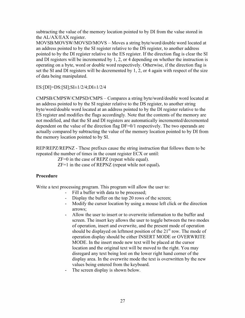
Procedure Write a text processing program. This program will allow the user to:
- Fill a buffer with data to be processed; - Display the buffer on the top 20 rows of the screen; - Modify the cursor location by using a mouse left click or the direction
arrows; - Allow the user to insert or to overwrite information to the buffer and
screen. The insert key allows the user to toggle between the two modes of operation, insert and overwrite, and the present mode of operation should be displayed on leftmost position of the 21st row. The mode of operation display should be either INSERT MODE or OVERWRITE MODE. In the insert mode new text will be placed at the cursor location and the original text will be moved to the right. You may disregard any text being lost on the lower right hand corner of the display area. In the overwrite mode the text is overwritten by the new values being entered from the keyboard.
- The screen display is shown below.

28
You may create any subroutine you may feel necessary, and make sure they are properly commented.
This area is where the buffer is to be displayed
INSERT MODE
This area is where status and controls choices are displayed.
29
Experiment 5 – Text Editor In this experiment you will expand the text editor you started working in experiment 4. The new functions you will implement are described below:
- Implement the backspace function. This function will be activated when the backspace key is pressed on the keyboard and it will delete the first character to the left of the cursor and update the cursor accordingly;
- Implement the home function. This function will be activated when the Home key is pressed on the keyboard and it will set the cursor the first position on the buffer.
- Implement the end function. This function will be activated when the End key is pressed on the keyboard and it will set the cursor the last position on the buffer.
- Implement the delete function. This function will be activated when the Delete key is pressed on the keyboard and it will delete the character where the cursor is located and move the text that follows that position one position to the left. Insert spaces at the end of the buffer;
- Implement the find function. This function will be activated when the CTRL+f keys (check Chapter 3 Int 16H) are pressed and this function will request the user enter the string of information to be searched on the buffer. The string should be entered on the 22nd row. If the string is found the cursor should be updated to be at the first location of the string on the screen. At this point the user will be asked if the search should continue and then subsequent strings may be located. In case the strings are not found an appropriate message should be displayed on the 23rd row;
- Implement the replace function. This function will be activated when the CTRL+h (check Chapter 3 Int 16H) keys are pressed and this function will request the user enter the string of information to be searched and replaced on the buffer. The string should be entered on the 22nd (searched string) and 23rd (replacement string) rows. If the string is found the user should be asked if the replacement should take place. If the user selects yes, then the string is replaced and the search resumes, and if the user selects no then the search resumes. In case the searched string is not found the an appropriate message is displayed on 24th row. Avoid writing any character to the last location of the 24th row otherwise the screen will roll upwards.
30
Experiment 6 - Parallel Communication Communication is required between a microprocessor and some device external to the computing system. This communication may be done serially or in parallel. In a parallel port, several signal lines are used to exchange information with other devices. This information is exchanged in multiple bits at a time, unlike a serial port where information is transferred one bit at a time over a single transmission line. The parallel port provided with a PC was originally designed as a port to be interfaced to a printer. Nowadays, this port is being used to interface the PC to devices such as: scanners, video capture devices, external disk drives, test equipment (scopes, multimeters, etc), and other equipment. Since its inception, the parallel printer port has being modified several times to make it a faster and more versatile means of interfacing devices to the PC. Today one may find the following types of parallel printer ports:
Original (SPP - Standard Parallel Port) PS/2-type (simple bi-directional) EPP – Enhanced Parallel Port ECP – Extended Capabilities Port.
This experiment uses the SPP type port, which was the original parallel printer port, and it had the following layout. Three consecutive addresses defined as follows were used. The first address, the port base address, which is also called the Data register, is used to output information to 8 data lines. The second address, base address + 1, also called the Status register, is used to input the state of 5 status lines. The third address, base address + 2, also called the Control register, is used to output values into 4 control lines. The standard base addresses are: 278h, 378h and 3BCh. Table 1 in Appendix B describes the different signals, arranged by registers, which are used by the SPP. One may access ports with the Intel 80x86 family of microprocessors, by the use of the IN and OUT instructions. Their formats are given below:
IN Destination, Source
Where:
Source can be an immediate address or the address in the DX register.
Destination can be the data in the AL, AX, or EAX registers.
Example: MOV DX,379H
IN AL,DX
31
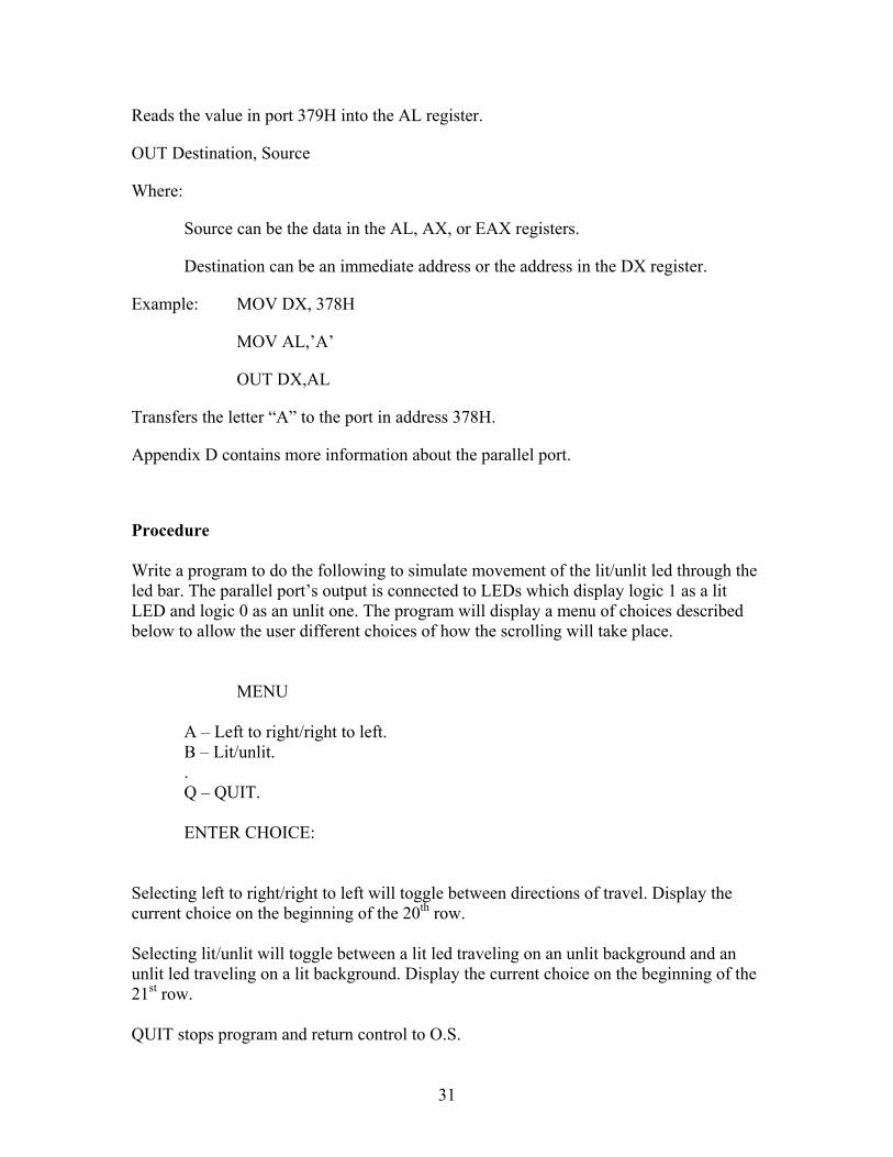
Reads the value in port 379H into the AL register.
OUT Destination, Source
Where:
Source can be the data in the AL, AX, or EAX registers.
Destination can be an immediate address or the address in the DX register.
Example: MOV DX, 378H
MOV AL,’A’
OUT DX,AL
Transfers the letter “A” to the port in address 378H.
Appendix D contains more information about the parallel port.
Procedure Write a program to do the following to simulate movement of the lit/unlit led through the led bar. The parallel port’s output is connected to LEDs which display logic 1 as a lit LED and logic 0 as an unlit one. The program will display a menu of choices described below to allow the user different choices of how the scrolling will take place.
MENU A – Left to right/right to left. B – Lit/unlit. . Q – QUIT. ENTER CHOICE:
Selecting left to right/right to left will toggle between directions of travel. Display the current choice on the beginning of the 20th row. Selecting lit/unlit will toggle between a lit led traveling on an unlit background and an unlit led traveling on a lit background. Display the current choice on the beginning of the 21st row. QUIT stops program and return control to O.S.
32
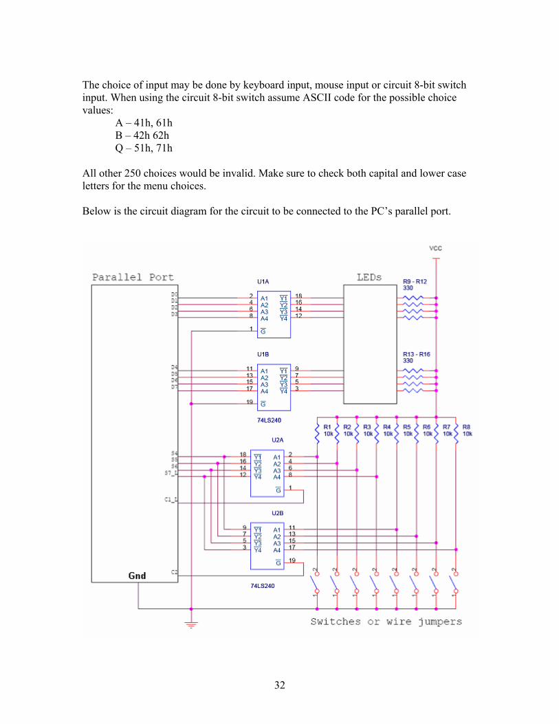
The choice of input may be done by keyboard input, mouse input or circuit 8-bit switch input. When using the circuit 8-bit switch assume ASCII code for the possible choice values:
A – 41h, 61h B – 42h 62h Q – 51h, 71h
All other 250 choices would be invalid. Make sure to check both capital and lower case letters for the menu choices. Below is the circuit diagram for the circuit to be connected to the PC’s parallel port.
33
Experiment 7 - Parallel Communication II The PS2 protocol modified the parallel port in a very important way. It allowed the data register to become bidirectional thus allowing it to output data to an external device such as some LEDs or to input values from a keyboard. This modification entailed the addition of some extra bits in the control register with the sole purpose of enabling interrupt (bit 4) and making the port an input port bit 5). The table shown on the next page describes what the new bits mean. Notice that these bits are used internally by the computer’s parallel port circuitry and they are not accessible from the outside.
Procedure
Write a program to simulate a mod(256) binary counter. Each number should be output to eight LEDs connected to the data register of the parallel port. A lit LED signifies a logic 1 value, while an unlit one signifies a logic 0.
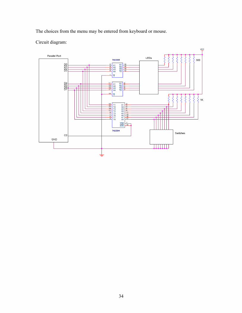
Assemble the circuit shown in the logic diagram below. Make sure your circuit’s ground and the computer ground are the same.
Part 1 - Write a program to count in binary from 0 to 255 and display the count on the LEDs.
Part 2 – Modify the program from part one so that the starting and final count will be numbers read from the data register. The following menu of choices should be displayed.
MENU 1 – MODULO 256 2 – VARIABLE MODULI. Q – QUIT. ENTER CHOICE:
Explanation of choices: MODULO 256 simulates a modulo 256 binary up counter. VARIABLE MODULI simulates an up counter which start and ending count will be entered from the data register. QUIT stops program and return control to O.S.
34
The choices from the menu may be entered from keyboard or mouse. Circuit diagram:
35
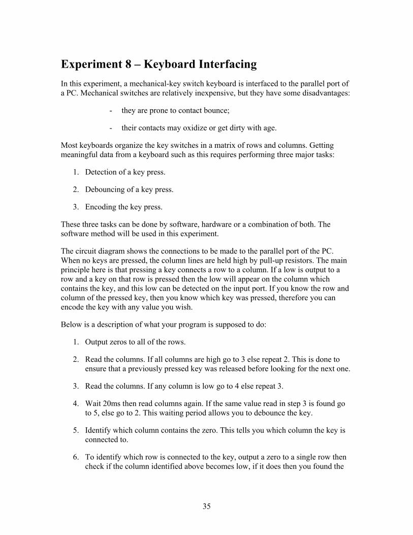
Experiment 8 – Keyboard Interfacing In this experiment, a mechanical-key switch keyboard is interfaced to the parallel port of a PC. Mechanical switches are relatively inexpensive, but they have some disadvantages:
- they are prone to contact bounce;
- their contacts may oxidize or get dirty with age.
Most keyboards organize the key switches in a matrix of rows and columns. Getting meaningful data from a keyboard such as this requires performing three major tasks:
1. Detection of a key press.
2. Debouncing of a key press.
3. Encoding the key press.
These three tasks can be done by software, hardware or a combination of both. The software method will be used in this experiment.
The circuit diagram shows the connections to be made to the parallel port of the PC. When no keys are pressed, the column lines are held high by pull-up resistors. The main principle here is that pressing a key connects a row to a column. If a low is output to a row and a key on that row is pressed then the low will appear on the column which contains the key, and this low can be detected on the input port. If you know the row and column of the pressed key, then you know which key was pressed, therefore you can encode the key with any value you wish.
Below is a description of what your program is supposed to do:
1. Output zeros to all of the rows.
2. Read the columns. If all columns are high go to 3 else repeat 2. This is done to ensure that a previously pressed key was released before looking for the next one.
3. Read the columns. If any column is low go to 4 else repeat 3.
4. Wait 20ms then read columns again. If the same value read in step 3 is found go to 5, else go to 2. This waiting period allows you to debounce the key.
5. Identify which column contains the zero. This tells you which column the key is connected to.
6. To identify which row is connected to the key, output a zero to a single row then check if the column identified above becomes low, if it does then you found the
36
desired row, else repeat 6 for the next row. Do this until all rows have been checked.
7. Now that both row and column have been identified, the key can be encoded.
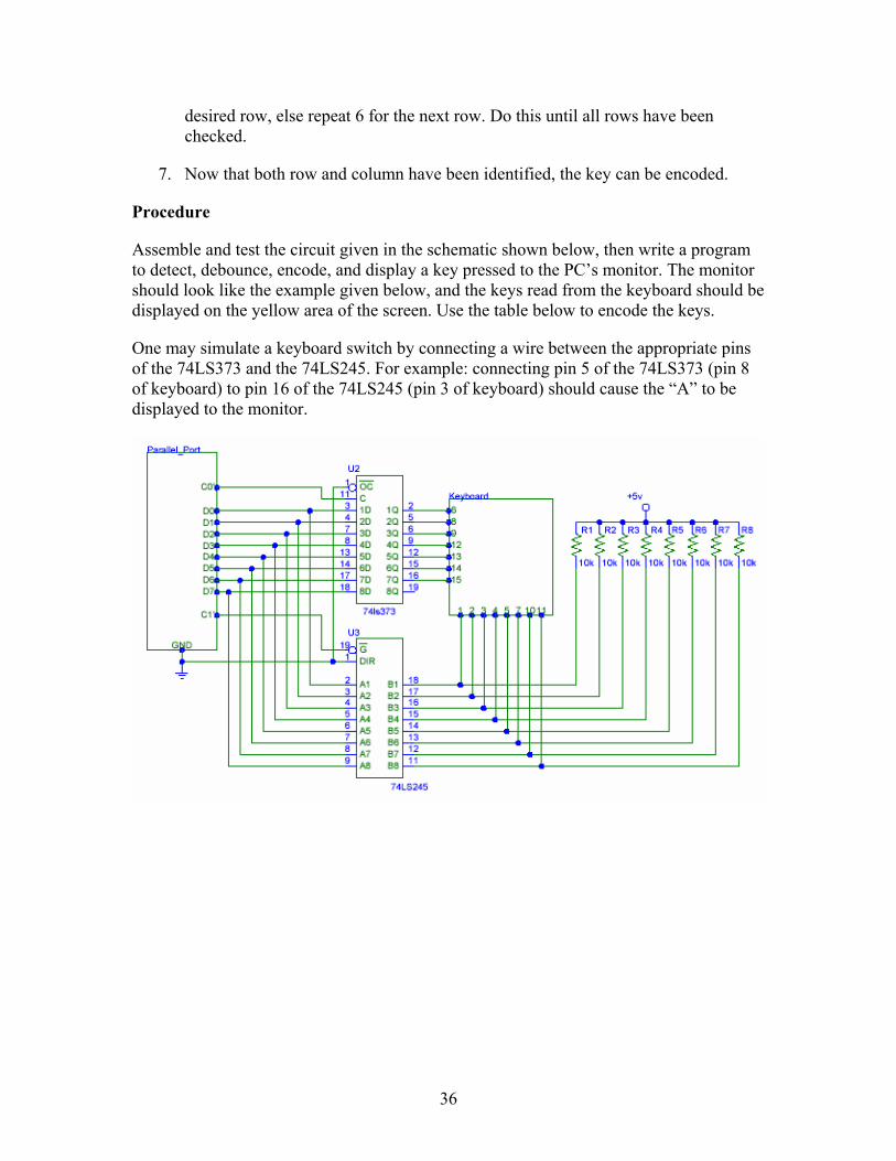
Procedure
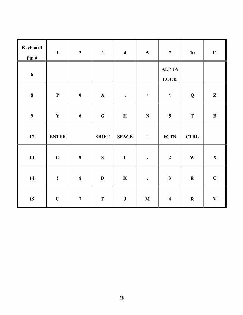
Assemble and test the circuit given in the schematic shown below, then write a program to detect, debounce, encode, and display a key pressed to the PC’s monitor. The monitor should look like the example given below, and the keys read from the keyboard should be displayed on the yellow area of the screen. Use the table below to encode the keys.
One may simulate a keyboard switch by connecting a wire between the appropriate pins of the 74LS373 and the 74LS245. For example: connecting pin 5 of the 74LS373 (pin 8 of keyboard) to pin 16 of the 74LS245 (pin 3 of keyboard) should cause the “A” to be displayed to the monitor.

37
Experiment 6 - Keyboard Interfacing.
38
Keyboard
Pin # 1 2 3 4 5 7 10 11
6 ALPHA
LOCK
8 P 0 A ; / \ Q Z
9 Y 6 G H N 5 T B
12 ENTER SHIFT SPACE = FCTN CTRL
13 O 9 S L . 2 W X
14 ! 8 D K , 3 E C
15 U 7 F J M 4 R V
39
Experiment 9 – Serial Communication
Computers use two methods to transfer information: serial and parallel. The parallel method allows the user to transfer information at faster rates but its hardware is more complex and expensive. Another problem with parallel communication is that the distance between the devices cannot be great. Serial communication overcomes some of the problem with parallel communication, so it is capable of transferring information at great distances and its hardware is less complex and cheaper. Serial communication can use the telephone network to send and receive information at great distances, due to the fact that it uses a single channel for information transfer. When using the telephone network the 0s and 1s that comprise the information being transferred have to be converted to audio tones. This function is performed by a device called modem, which stands for modulator/demodulator.
Two methods are used in serial communication:
Synchronous – information is transferred in block of data (characters) at a time;
Asynchronous – information is transferred one character at a time.
Special ICs have been designed by different manufactures to take care of serial communication. They are called:
UART – Universal asynchronous receiver-transmitter;
USART – Universal synchronous-asynchronous receiver-transmitter.
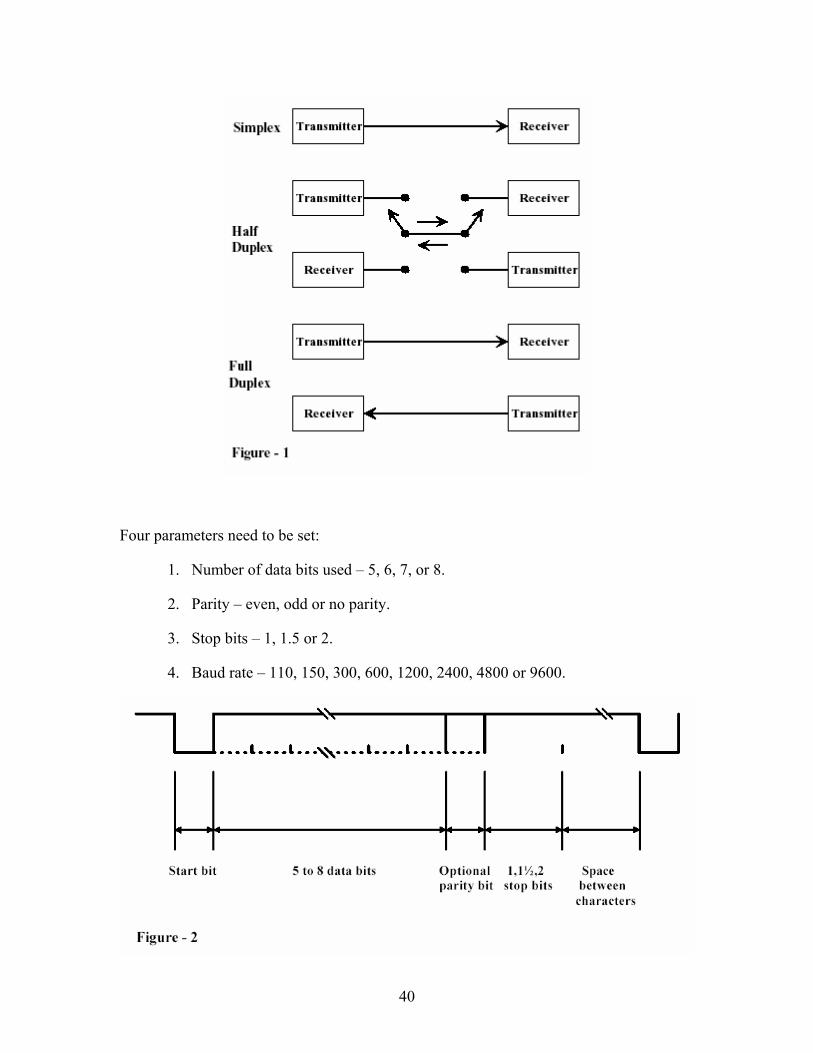
The transmission of data can be done in different ways. Simplex transmissions occur when a transmitter sends information to a receiver. The information flows in one way only, from the transmitter to the receiver. Information can also be transmitted and received simultaneously, over two transmission lines and this characterizes full duplex transmissions. Half duplex transmission is the method that uses a single transmission line to transfer data bi-directionally. Unlike the simplex method, the half duplex method allows information to flow both ways, one way at a time as shown in Figure -1.
In this experiment you are going to be using asynchronous serial communication. This form of serial communication is widely used for character-oriented transmissions. Each character is placed between a start and one or more stop bits, and this procedure is referred to as framing. The start bit is always a 0 (low) and the stop bits are always 1 (high). Between the start and stop bits one may find from 5 to 8 data bits and a parity bit in case parity is used for error checking.
As seen in the diagram shown in figure 2, information may be exchanged with more or less bits in each frame. This requires that the devices being used in the communication exchange be initialized in the manner the information will be transmitted and received.
40
Four parameters need to be set:
1. Number of data bits used – 5, 6, 7, or 8.
2. Parity – even, odd or no parity.
3. Stop bits – 1, 1.5 or 2.
4. Baud rate – 110, 150, 300, 600, 1200, 2400, 4800 or 9600.
41
5. .
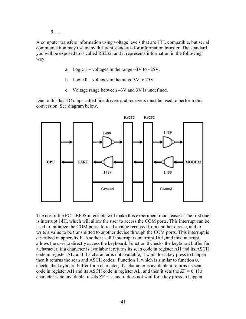
A computer transfers information using voltage levels that are TTL compatible, but serial communication may use many different standards for information transfer. The standard you will be exposed to is called RS232, and it represents information in the following way:
a. Logic 1 – voltages in the range –3V to –25V.
b. Logic 0 – voltages in the range 3V to 25V.
c. Voltage range between –3V and 3V is undefined.
Due to this fact IC chips called line drivers and receivers must be used to perform this conversion. See diagram below.
The use of the PC’s BIOS interrupts will make this experiment much easier. The first one is interrupt 14H, which will allow the user to access the COM ports. This interrupt can be used to initialize the COM ports, to read a value received from another device, and to write a value to be transmitted to another device through the COM ports. This interrupt is described in appendix E. Another useful interrupt is interrupt 16H, and this interrupt allows the user to directly access the keyboard. Function 0 checks the keyboard buffer for a character, if a character is available it returns its scan code in register AH and its ASCII code in register AL, and if a character is not available, it waits for a key press to happen then it returns the scan and ASCII codes. Function 1, which is similar to function 0, checks the keyboard buffer for a character, if a character is available it returns its scan code in register AH and its ASCII code in register AL, and then it sets the ZF = 0. If a character is not available, it sets ZF = 1, and it does not wait for a key press to happen.
42
Several tables describing the interrupt’s functions and PC’s scan codes are given in the appendix.
Procedure
Write a program to send and receive information through the serial port of the PC. This program should display the transmitted information on rows 18 through 23 of the screen, with blue characters on white background, and display the received data on rows 11 through 16 with blue characters on white background. The remaining of the screen should have an attribute for white foreground on blue background. On the upper eleven row the student should use his artistic abilities to write “Chat Box”. Be creative.
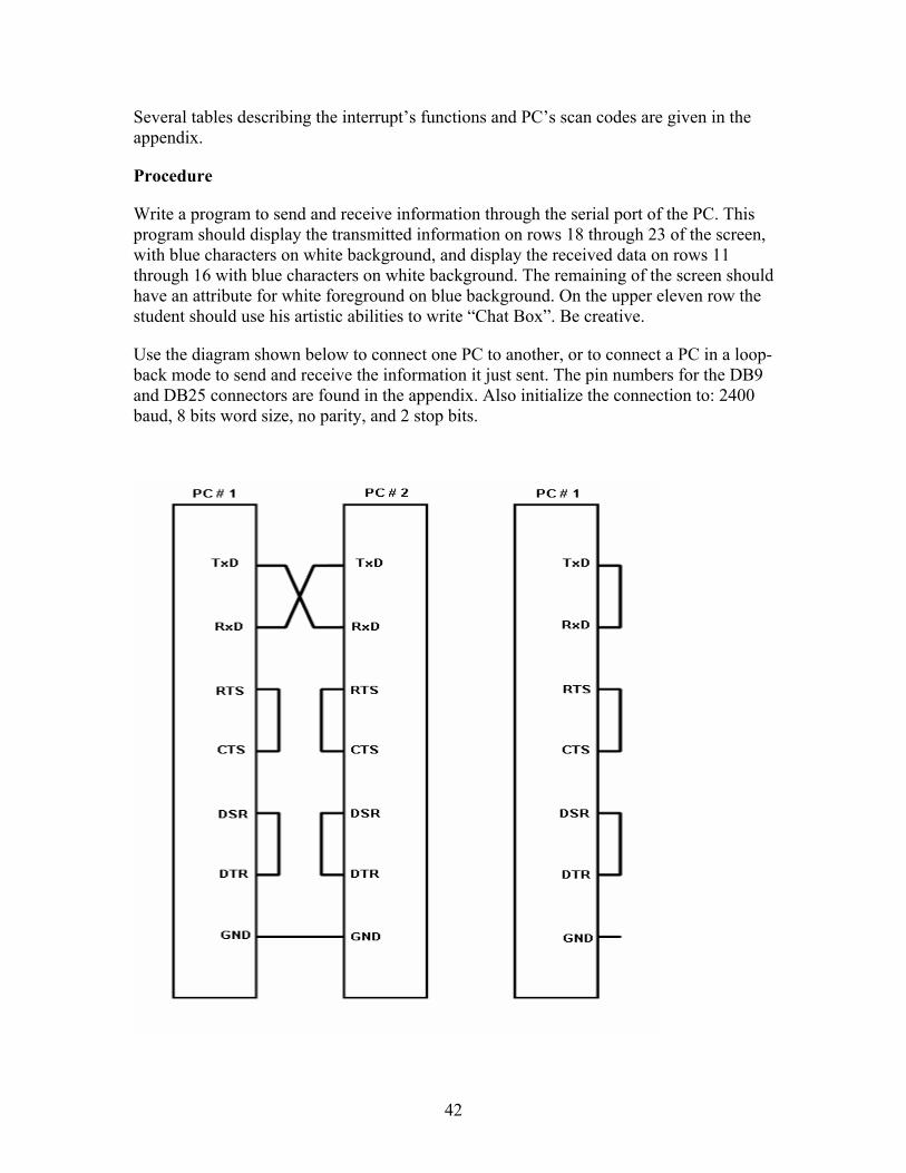
Use the diagram shown below to connect one PC to another, or to connect a PC in a loop-back mode to send and receive the information it just sent. The pin numbers for the DB9 and DB25 connectors are found in the appendix. Also initialize the connection to: 2400 baud, 8 bits word size, no parity, and 2 stop bits.
43
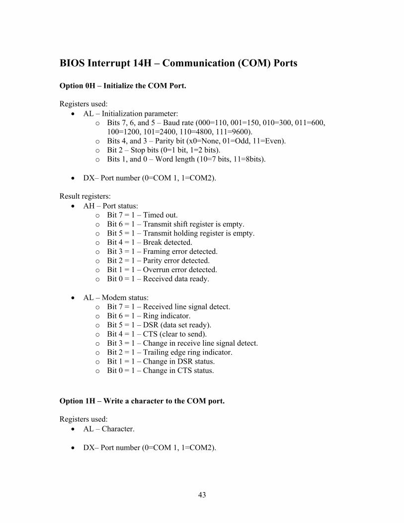
BIOS Interrupt 14H – Communication (COM) Ports Option 0H – Initialize the COM Port. Registers used:
• AL – Initialization parameter: o Bits 7, 6, and 5 – Baud rate (000=110, 001=150, 010=300, 011=600,
100=1200, 101=2400, 110=4800, 111=9600). o Bits 4, and 3 – Parity bit (x0=None, 01=Odd, 11=Even). o Bit 2 – Stop bits (0=1 bit, 1=2 bits). o Bits 1, and 0 – Word length (10=7 bits, 11=8bits).
• DX– Port number (0=COM 1, 1=COM2).
Result registers:
• AH – Port status: o Bit 7 = 1 – Timed out. o Bit 6 = 1 – Transmit shift register is empty. o Bit 5 = 1 – Transmit holding register is empty. o Bit 4 = 1 – Break detected. o Bit 3 = 1 – Framing error detected. o Bit 2 = 1 – Parity error detected. o Bit 1 = 1 – Overrun error detected. o Bit 0 = 1 – Received data ready.
• AL – Modem status:
o Bit 7 = 1 – Received line signal detect. o Bit 6 = 1 – Ring indicator. o Bit 5 = 1 – DSR (data set ready). o Bit 4 = 1 – CTS (clear to send). o Bit 3 = 1 – Change in receive line signal detect. o Bit 2 = 1 – Trailing edge ring indicator. o Bit 1 = 1 – Change in DSR status. o Bit 0 = 1 – Change in CTS status.
Option 1H – Write a character to the COM port. Registers used:
• AL – Character. • DX– Port number (0=COM 1, 1=COM2).
44
Result registers: • AH – Result of operation in bit 7 and port status in bit 6-0:
o Bit 7 = 0 – Operation successful o Bit 6 = 1 – Transmit shift register is empty. o Bit 5 = 1 – Transmit holding register is empty. o Bit 4 = 1 – Break detected. o Bit 3 = 1 – Framing error detected. o Bit 2 = 1 – Parity error detected. o Bit 1 = 1 – Overrun error detected. o Bit 0 = 1 – Received data ready.
• AL – Character.
Option 2H – Read a character from the COM port. Registers used:
• DX– Port number (0=COM 1, 1=COM2). Result registers:
• AH – Result of operation in bit 7 and port status in bit 6-0: o Bit 7 = 0 – Operation successful o Bit 6 = 1 – Transmit shift register is empty. o Bit 5 = 1 – Transmit holding register is empty. o Bit 4 = 1 – Break detected. o Bit 3 = 1 – Framing error detected. o Bit 2 = 1 – Parity error detected. o Bit 1 = 1 – Overrun error detected. o Bit 0 = 1 – Received data ready.
• AL – Character.
Option 3H – Read the COM Port status. Registers used:
• DX– Port number (0=COM 1, 1=COM2). Result registers:
• AH – Port status: o Bit 7 = 1 – Timed out. o Bit 6 = 1 – Transmit shift register is empty. o Bit 5 = 1 – Transmit holding register is empty.
45
o Bit 4 = 1 – Break detected. o Bit 3 = 1 – Framing error detected. o Bit 2 = 1 – Parity error detected. o Bit 1 = 1 – Overrun error detected. o Bit 0 = 1 – Received data ready.
• AL – Modem status:
o Bit 7 = 1 – Received line signal detect. o Bit 6 = 1 – Ring indicator. o Bit 5 = 1 – DSR (data set ready). o Bit 4 = 1 – CTS (clear to send). o Bit 3 = 1 – Change in receive line signal detect. o Bit 2 = 1 – Trailing edge ring indicator. o Bit 1 = 1 – Change in DSR status. o Bit 0 = 1 – Change in CTS status.
46
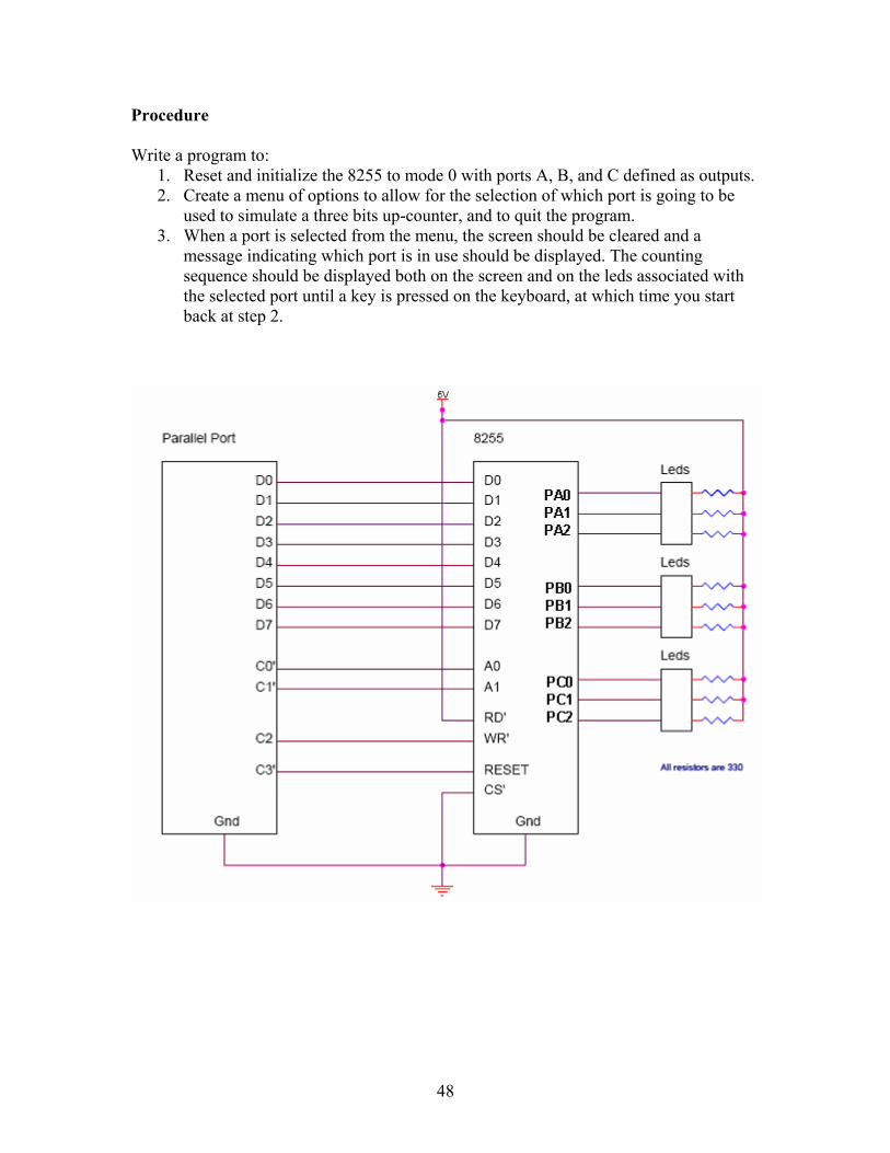
Experiment 10 – Interfacing the Intel 8255 to the Parallel Port
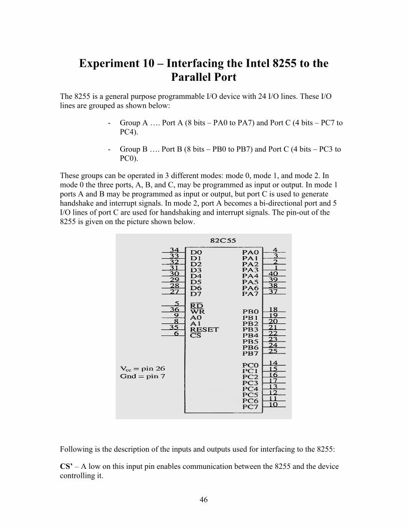
The 8255 is a general purpose programmable I/O device with 24 I/O lines. These I/O lines are grouped as shown below:
- Group A …. Port A (8 bits – PA0 to PA7) and Port C (4 bits – PC7 to PC4).
- Group B …. Port B (8 bits – PB0 to PB7) and Port C (4 bits – PC3 to PC0).
These groups can be operated in 3 different modes: mode 0, mode 1, and mode 2. In mode 0 the three ports, A, B, and C, may be programmed as input or output. In mode 1 ports A and B may be programmed as input or output, but port C is used to generate handshake and interrupt signals. In mode 2, port A becomes a bi-directional port and 5 I/O lines of port C are used for handshaking and interrupt signals. The pin-out of the 8255 is given on the picture shown below.
Following is the description of the inputs and outputs used for interfacing to the 8255:
CS’ – A low on this input pin enables communication between the 8255 and the device controlling it.
47
RD’ – A low on this input pin enables the 8255 to send data or status information to the device controlling the 8255.
WR’ – A low on this input pin enables the device controlling the 8255 to write data or control words to the 8255.
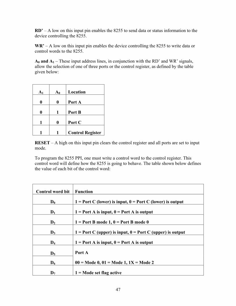
A0 and A1 – These input address lines, in conjunction with the RD’ and WR’ signals, allow the selection of one of three ports or the control register, as defined by the table given below:
A1 A0 Location
0 0 Port A
0 1 Port B
1 0 Port C
1 1 Control Register
RESET – A high on this input pin clears the control register and all ports are set to input mode.
To program the 8255 PPI, one must write a control word to the control register. This control word will define how the 8255 is going to behave. The table shown below defines the value of each bit of the control word:
Control word bit Function
D0 1 = Port C (lower) is input, 0 = Port C (lower) is output
D1 1 = Port A is input, 0 = Port A is output
D2 1 = Port B mode 1, 0 = Port B mode 0
D3 1 = Port C (upper) is input, 0 = Port C (upper) is output
D4 1 = Port A is input, 0 = Port A is output
D5
D6
Port A
00 = Mode 0, 01 = Mode 1, 1X = Mode 2
D7 1 = Mode set flag active
48
Procedure Write a program to:
1. Reset and initialize the 8255 to mode 0 with ports A, B, and C defined as outputs. 2. Create a menu of options to allow for the selection of which port is going to be
used to simulate a three bits up-counter, and to quit the program. 3. When a port is selected from the menu, the screen should be cleared and a
message indicating which port is in use should be displayed. The counting sequence should be displayed both on the screen and on the leds associated with the selected port until a key is pressed on the keyboard, at which time you start back at step 2.
49
Appendix A – DOS Commands
CD or CHDIR
CD (Change Directory) is a command used to switch directories in MS-DOS.
SYNTAX
CHDIR [drive:][path] CHDIR[..] CD [drive:][path] CD[..]
EXAMPLES
cd\
Changes the directory to the root directory of the drive.
cd..
Goes back one directory.
cd work
Changes from the present directory to the subdirectory called work
cd\work
The directory would initially be changed to the root directory and then to the work directory. CLS CLS is a command that clears contents of the screen, leaving only a prompt. SYNTAX CLS
COPY
Copy one or more files to another location.
SYNTAX
50
COPY [/A | /B] source [destination] [/A | /B]] [/V] [/Y | /-Y]
source Specifies the file or files to be copied. /A Indicates an ASCII text file. /B Indicates a binary file. destination Specifies the directory and/or filename for the new file(s). /V Verifies that new files are written correctly.
/Y Suppresses prompting to confirm you want to overwrite an existing destination file.
/-Y Causes prompting to confirm you want to overwrite an existing destination file.
To append files, specify a single file for destination, but multiple files for source (using wildcards or file1+file2+file3 format).
EXAMPLES
copy *.* a:
Copy all files in the current directory to the floppy disk in drive a:
copy file1.txt+file2.txt
Copy the contents of file2.txt and combine it with the contents of file1.txt.
DIR
Displays a list of files and subdirectories in a directory.
SYNTAX
DIR [drive:][path][filename] [/A[[:]attributes]] [/B] [/C] [/D] [/L] [/N] [/O[[:]sortorder]] [/P] [/Q] [/S] [/T[[:]timefield]] [/W] [/X] [/4]
[drive:][path][filename] Specifies drive, directory, and/or files to list. Attributes D Directories
R Read-only files H Hidden files A Files ready for archiving S System files - Prefix meaning not
/B Uses bare format (no heading information or summary). /C Display the thousand separator in file sizes. This is the default.
Use /-C to disable display of separator. /D Same as wide but files are list sorted by column. /L Uses lowercase.
51
/N New long list format where filenames are on the far right. /O List by files in sorted order. Sortorder N By name (alphabetic)
S By size (smallest first) E By extension (alphabetic) D By date/time (oldest first) G Group directories first - Prefix to reverse order
/P Pauses after each screenful of information. /Q Display the owner of the file. /S Displays files in specified directory and all subdirectories. /T Controls which time field displayed or used for sorting Timefield C Creation
A Last Access W Last Written
/W Uses wide list format. /X This displays the short names generated for non-8dot3 file
names. The format is that of /N with the short name inserted before the long name. If no short name is present, blanks are displayed in its place.
/4 Displays four-digit years
EXAMPLES
dir
Lists all files and directories in the directory that you are currently in.
dir /p
Using this command will display all files one page at a time. Useful when the number of files exceed what can be displayed in a single page.
52
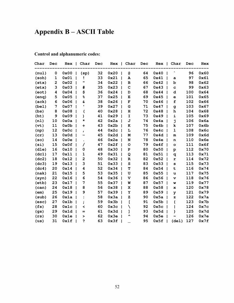
Appendix B – ASCII Table
Control and alphanumeric codes: Char Dec Hex | Char Dec Hex | Char Dec Hex | Char Dec Hex --------------------------------------------------------------------- (nul) 0 0x00 | (sp) 32 0x20 | @ 64 0x40 | ` 96 0x60 (soh) 1 0x01 | ! 33 0x21 | A 65 0x41 | a 97 0x61 (stx) 2 0x02 | " 34 0x22 | B 66 0x42 | b 98 0x62 (etx) 3 0x03 | # 35 0x23 | C 67 0x43 | c 99 0x63 (eot) 4 0x04 | $ 36 0x24 | D 68 0x44 | d 100 0x64 (enq) 5 0x05 | % 37 0x25 | E 69 0x45 | e 101 0x65 (ack) 6 0x06 | & 38 0x26 | F 70 0x46 | f 102 0x66 (bel) 7 0x07 | ' 39 0x27 | G 71 0x47 | g 103 0x67 (bs) 8 0x08 | ( 40 0x28 | H 72 0x48 | h 104 0x68 (ht) 9 0x09 | ) 41 0x29 | I 73 0x49 | i 105 0x69 (nl) 10 0x0a | * 42 0x2a | J 74 0x4a | j 106 0x6a (vt) 11 0x0b | + 43 0x2b | K 75 0x4b | k 107 0x6b (np) 12 0x0c | , 44 0x2c | L 76 0x4c | l 108 0x6c (cr) 13 0x0d | - 45 0x2d | M 77 0x4d | m 109 0x6d (so) 14 0x0e | . 46 0x2e | N 78 0x4e | n 110 0x6e (si) 15 0x0f | / 47 0x2f | O 79 0x4f | o 111 0x6f (dle) 16 0x10 | 0 48 0x30 | P 80 0x50 | p 112 0x70 (dc1) 17 0x11 | 1 49 0x31 | Q 81 0x51 | q 113 0x71 (dc2) 18 0x12 | 2 50 0x32 | R 82 0x52 | r 114 0x72 (dc3) 19 0x13 | 3 51 0x33 | S 83 0x53 | s 115 0x73 (dc4) 20 0x14 | 4 52 0x34 | T 84 0x54 | t 116 0x74 (nak) 21 0x15 | 5 53 0x35 | U 85 0x55 | u 117 0x75 (syn) 22 0x16 | 6 54 0x36 | V 86 0x56 | v 118 0x76 (etb) 23 0x17 | 7 55 0x37 | W 87 0x57 | w 119 0x77 (can) 24 0x18 | 8 56 0x38 | X 88 0x58 | x 120 0x78 (em) 25 0x19 | 9 57 0x39 | Y 89 0x59 | y 121 0x79 (sub) 26 0x1a | : 58 0x3a | Z 90 0x5a | z 122 0x7a (esc) 27 0x1b | ; 59 0x3b | [ 91 0x5b | { 123 0x7b (fs) 28 0x1c | < 60 0x3c | \ 92 0x5c | | 124 0x7c (gs) 29 0x1d | = 61 0x3d | ] 93 0x5d | } 125 0x7d (rs) 30 0x1e | > 62 0x3e | ^ 94 0x5e | ~ 126 0x7e (us) 31 0x1f | ? 63 0x3f | _ 95 0x5f | (del) 127 0x7f
53
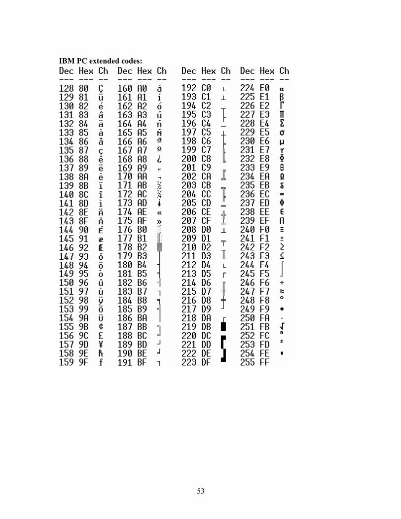
IBM PC extended codes:

54
Appendix C – Datasheets 1. Device datasheets are easily found by searching the internet with your favorite
search engine. Search for the part number, i.e., 74LS08.
2. Request the TTL Logic book from the Monitor in room 128. You will need to present your student id to be able to use the book.
55
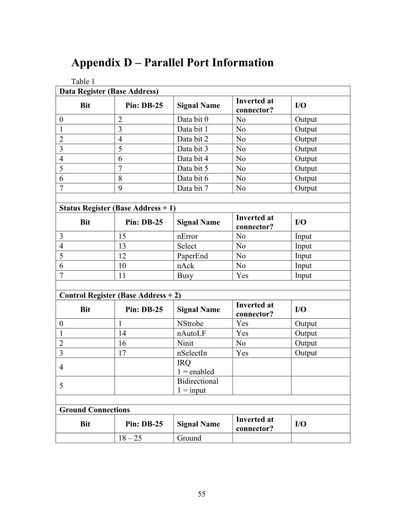
Appendix D – Parallel Port Information
Table 1 Data Register (Base Address)
Bit Pin: DB-25 Signal Name Inverted at connector? I/O
0 2 Data bit 0 No Output 1 3 Data bit 1 No Output 2 4 Data bit 2 No Output 3 5 Data bit 3 No Output 4 6 Data bit 4 No Output 5 7 Data bit 5 No Output 6 8 Data bit 6 No Output 7 9 Data bit 7 No Output Status Register (Base Address + 1)
Bit Pin: DB-25 Signal Name Inverted at connector? I/O
3 15 nError No Input 4 13 Select No Input 5 12 PaperEnd No Input 6 10 nAck No Input 7 11 Busy Yes Input Control Register (Base Address + 2)
Bit Pin: DB-25 Signal Name Inverted at connector? I/O
0 1 NStrobe Yes Output 1 14 nAutoLF Yes Output 2 16 Ninit No Output 3 17 nSelectIn Yes Output
4 IRQ 1 = enabled
5 Bidirectional 1 = input
Ground Connections
Bit Pin: DB-25 Signal Name Inverted at connector? I/O
18 – 25 Ground
56
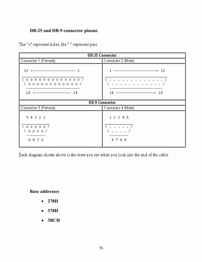
DB-25 and DB-9 connector pinout.
Base addresses
• 278H
• 378H
• 3BCH
57
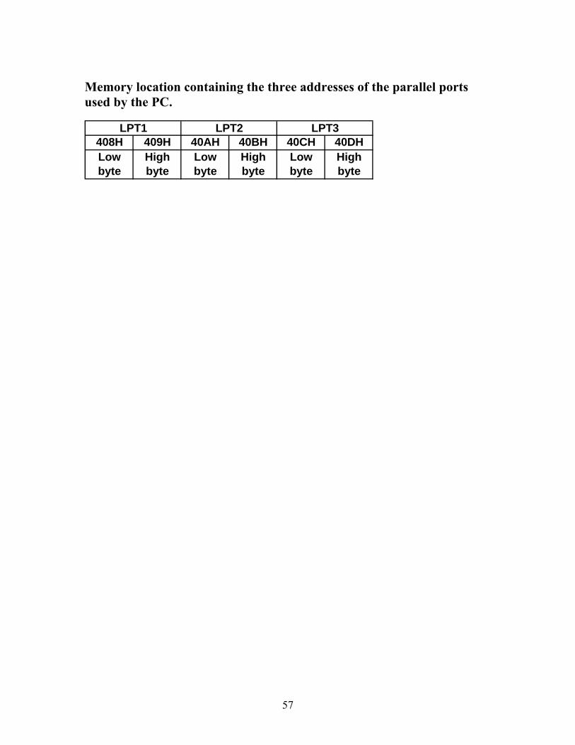
Memory location containing the three addresses of the parallel ports used by the PC.
408H 409H 40AH 40BH 40CH 40DHLow byte
High byte
Low byte
High byte
Low byte
High byte
LPT1 LPT2 LPT3
58
Appendix E – Serial Port Information
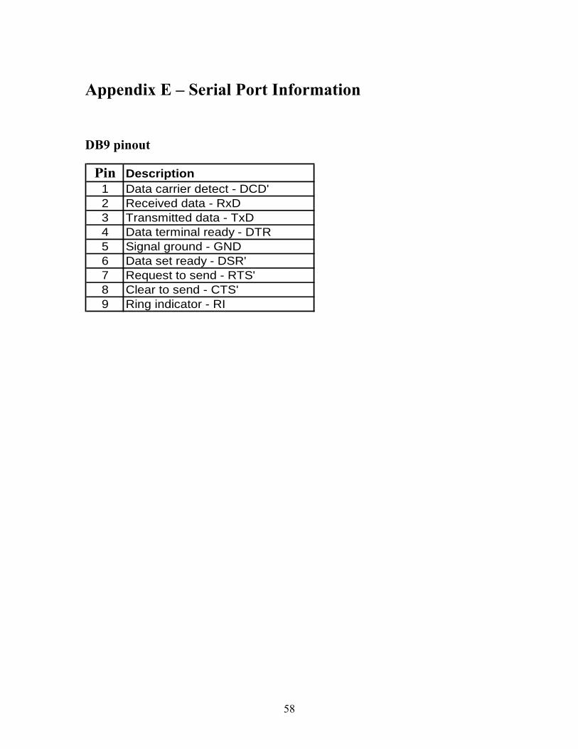
DB9 pinout
Pin Description1 Data carrier detect - DCD'2 Received data - RxD3 Transmitted data - TxD4 Data terminal ready - DTR5 Signal ground - GND6 Data set ready - DSR'7 Request to send - RTS'8 Clear to send - CTS'9 Ring indicator - RI
59
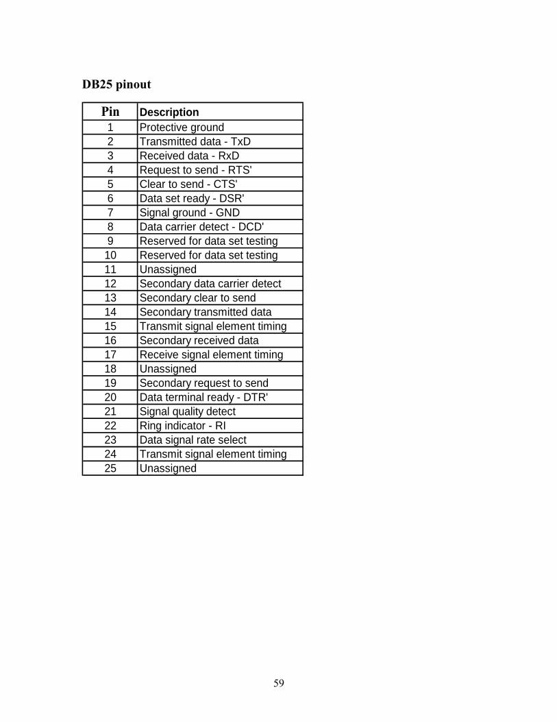
DB25 pinout
Pin Description1 Protective ground2 Transmitted data - TxD3 Received data - RxD4 Request to send - RTS'5 Clear to send - CTS'6 Data set ready - DSR'7 Signal ground - GND8 Data carrier detect - DCD'9 Reserved for data set testing10 Reserved for data set testing11 Unassigned12 Secondary data carrier detect13 Secondary clear to send14 Secondary transmitted data15 Transmit signal element timing16 Secondary received data17 Receive signal element timing18 Unassigned19 Secondary request to send20 Data terminal ready - DTR'21 Signal quality detect22 Ring indicator - RI23 Data signal rate select24 Transmit signal element timing25 Unassigned