Embed Size (px)
Citation preview
EE462L, Power Electronics, Capacitor Filtered Diode Bridge Rectifier Version Sept. 2, 2011
Page 1 of 16
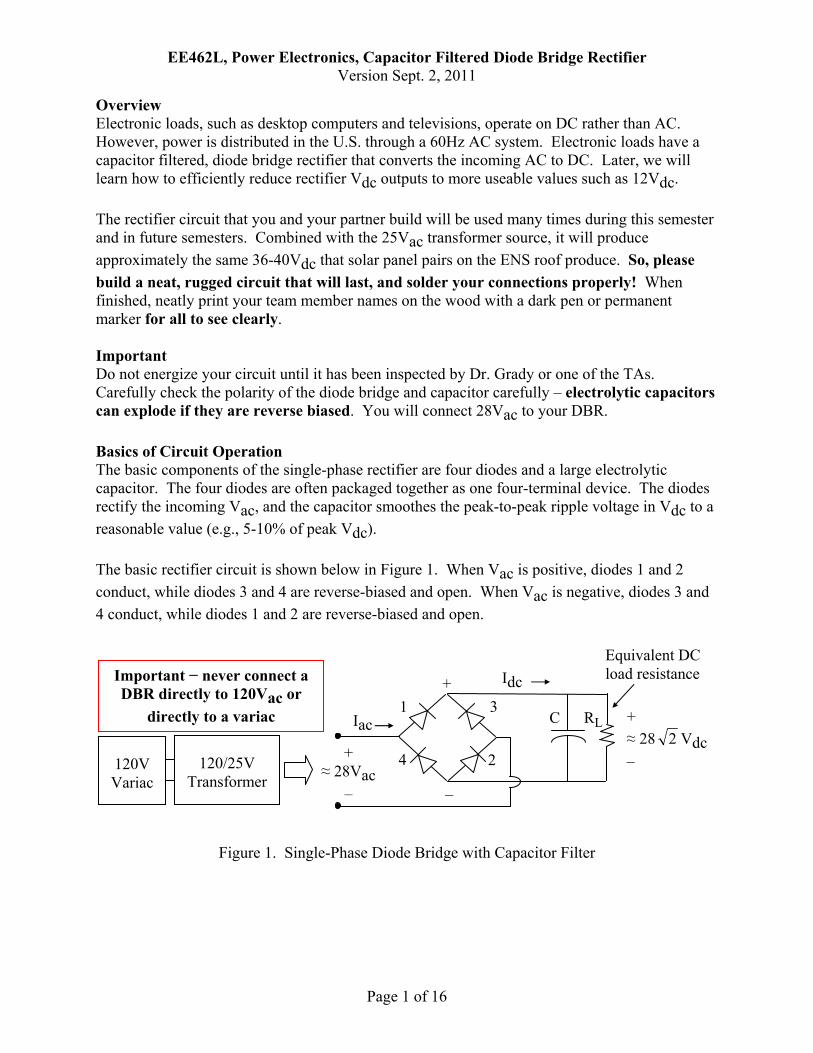
Overview Electronic loads, such as desktop computers and televisions, operate on DC rather than AC. However, power is distributed in the U.S. through a 60Hz AC system. Electronic loads have a capacitor filtered, diode bridge rectifier that converts the incoming AC to DC. Later, we will learn how to efficiently reduce rectifier Vdc outputs to more useable values such as 12Vdc. The rectifier circuit that you and your partner build will be used many times during this semester and in future semesters. Combined with the 25Vac transformer source, it will produce approximately the same 36-40Vdc that solar panel pairs on the ENS roof produce. So, please build a neat, rugged circuit that will last, and solder your connections properly! When finished, neatly print your team member names on the wood with a dark pen or permanent marker for all to see clearly. Important Do not energize your circuit until it has been inspected by Dr. Grady or one of the TAs. Carefully check the polarity of the diode bridge and capacitor carefully – electrolytic capacitors can explode if they are reverse biased. You will connect 28Vac to your DBR. Basics of Circuit Operation The basic components of the single-phase rectifier are four diodes and a large electrolytic capacitor. The four diodes are often packaged together as one four-terminal device. The diodes rectify the incoming Vac, and the capacitor smoothes the peak-to-peak ripple voltage in Vdc to a reasonable value (e.g., 5-10% of peak Vdc). The basic rectifier circuit is shown below in Figure 1. When Vac is positive, diodes 1 and 2 conduct, while diodes 3 and 4 are reverse-biased and open. When Vac is negative, diodes 3 and 4 conduct, while diodes 1 and 2 are reverse-biased and open.
Figure 1. Single-Phase Diode Bridge with Capacitor Filter
120/25V
Transformer
120V Variac
Important − never connect a DBR directly to 120Vac or
directly to a variac
+
–
+ ≈ 28Vac
–
1
4
3
2
Equivalent DC load resistance
+ ≈ 28 2 Vdc –
RL C Iac
Idc
EE462L, Power Electronics, Capacitor Filtered Diode Bridge Rectifier Version Sept. 2, 2011
Page 2 of 16
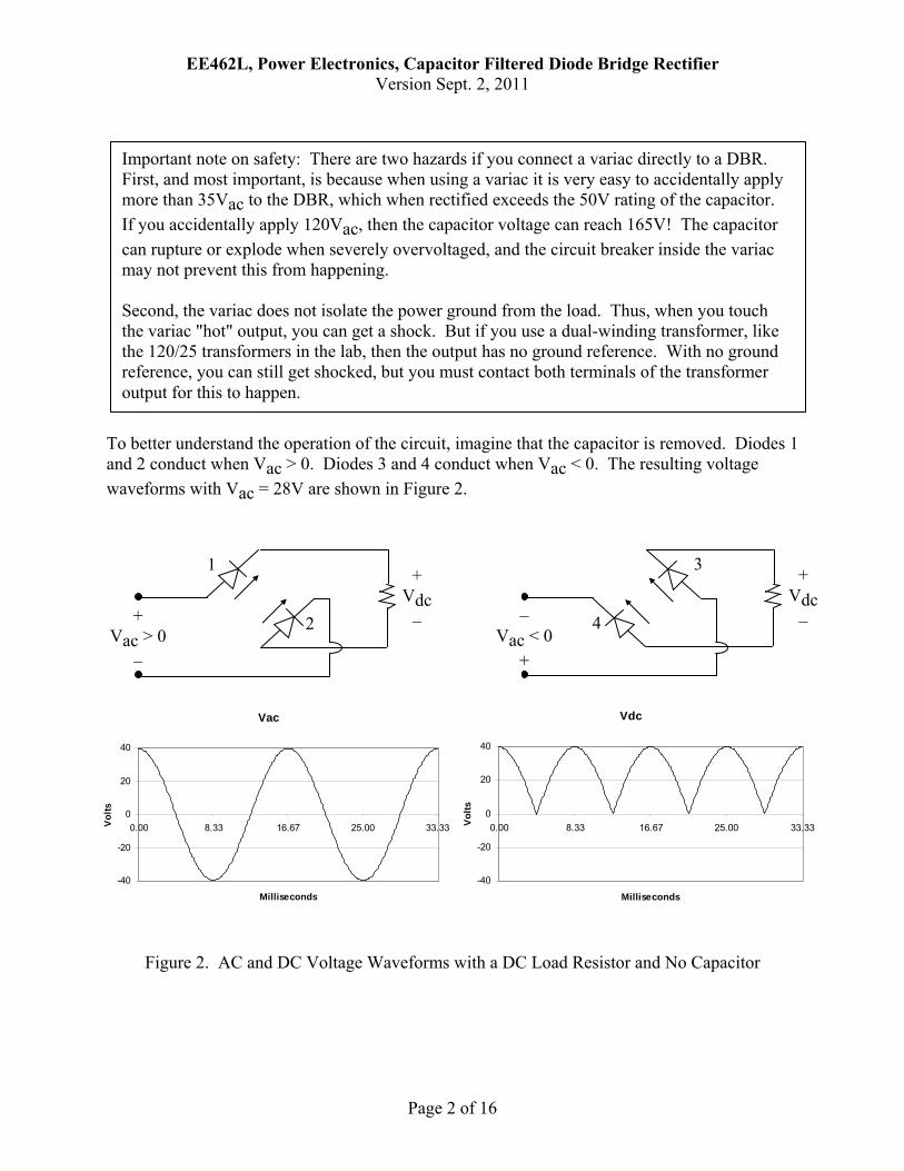
To better understand the operation of the circuit, imagine that the capacitor is removed. Diodes 1 and 2 conduct when Vac > 0. Diodes 3 and 4 conduct when Vac < 0. The resulting voltage waveforms with Vac = 28V are shown in Figure 2.
Figure 2. AC and DC Voltage Waveforms with a DC Load Resistor and No Capacitor
Important note on safety: There are two hazards if you connect a variac directly to a DBR. First, and most important, is because when using a variac it is very easy to accidentally apply more than 35Vac to the DBR, which when rectified exceeds the 50V rating of the capacitor. If you accidentally apply 120Vac, then the capacitor voltage can reach 165V! The capacitor can rupture or explode when severely overvoltaged, and the circuit breaker inside the variac may not prevent this from happening. Second, the variac does not isolate the power ground from the load. Thus, when you touch the variac "hot" output, you can get a shock. But if you use a dual-winding transformer, like the 120/25 transformers in the lab, then the output has no ground reference. With no ground reference, you can still get shocked, but you must contact both terminals of the transformer output for this to happen.
Vac
-40
-20
0
20
40
0.00 8.33 16.67 25.00 33.33
Milliseconds
Volts
Vdc
-40
-20
0
20
40
0.00 8.33 16.67 25.00 33.33
Milliseconds
Volts
+ Vac > 0
–
1
2
+ Vdc
– – Vac < 0
+
4
3 + Vdc
–
EE462L, Power Electronics, Capacitor Filtered Diode Bridge Rectifier Version Sept. 2, 2011
Page 3 of 16
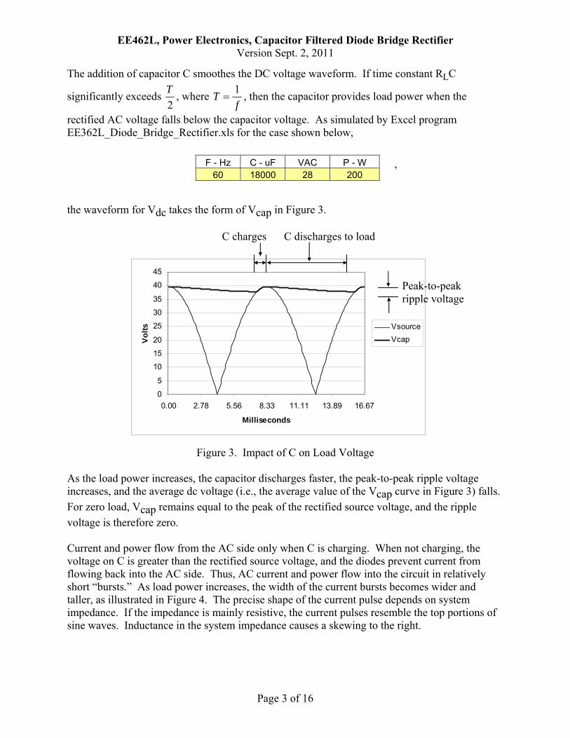
The addition of capacitor C smoothes the DC voltage waveform. If time constant RLC
significantly exceeds 2T , where
fT 1= , then the capacitor provides load power when the
rectified AC voltage falls below the capacitor voltage. As simulated by Excel program EE362L_Diode_Bridge_Rectifier.xls for the case shown below, the waveform for Vdc takes the form of Vcap in Figure 3.
Figure 3. Impact of C on Load Voltage As the load power increases, the capacitor discharges faster, the peak-to-peak ripple voltage increases, and the average dc voltage (i.e., the average value of the Vcap curve in Figure 3) falls. For zero load, Vcap remains equal to the peak of the rectified source voltage, and the ripple voltage is therefore zero. Current and power flow from the AC side only when C is charging. When not charging, the voltage on C is greater than the rectified source voltage, and the diodes prevent current from flowing back into the AC side. Thus, AC current and power flow into the circuit in relatively short “bursts.” As load power increases, the width of the current bursts becomes wider and taller, as illustrated in Figure 4. The precise shape of the current pulse depends on system impedance. If the impedance is mainly resistive, the current pulses resemble the top portions of sine waves. Inductance in the system impedance causes a skewing to the right.
0
5
10
15
20
25
30
35
40
45
0.00 2.78 5.56 8.33 11.11 13.89 16.67
Milliseconds
Volts Vsource
Vcap
Peak-to-peak ripple voltage
C charges C discharges to load
, F - Hz C - uF VAC P - W 60 18000 28 200
EE462L, Power Electronics, Capacitor Filtered Diode Bridge Rectifier Version Sept. 2, 2011
Page 4 of 16
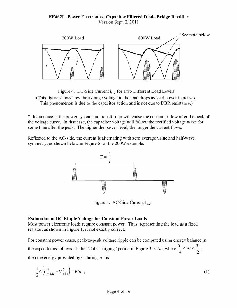
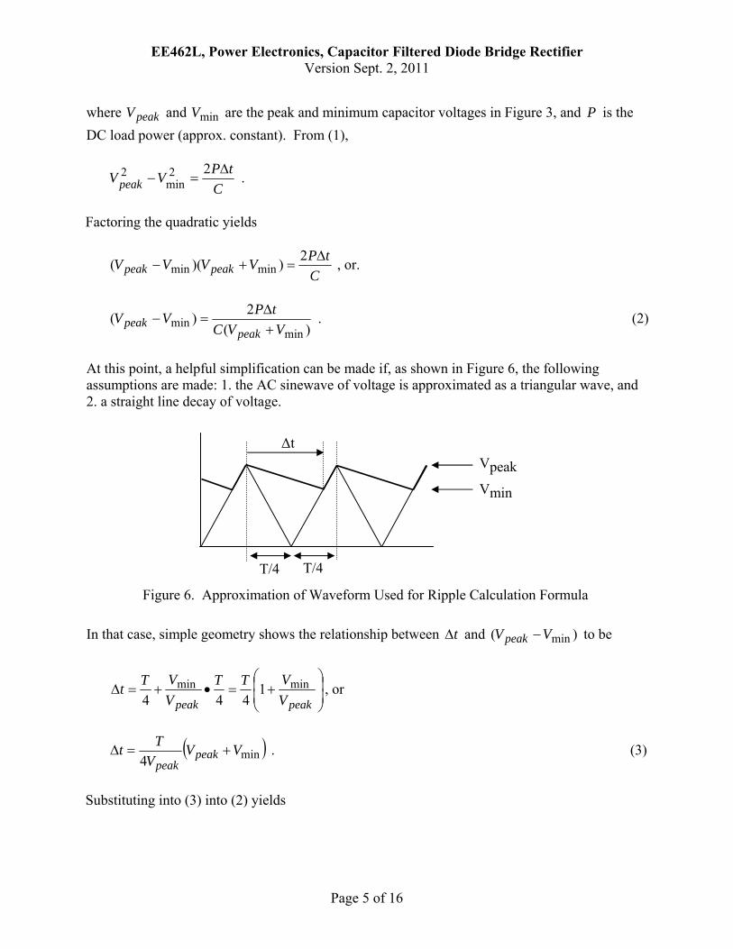
* Inductance in the power system and transformer will cause the current to flow after the peak of the voltage curve. In that case, the capacitor voltage will follow the rectified voltage wave for some time after the peak. The higher the power level, the longer the current flows. Reflected to the AC-side, the current is alternating with zero average value and half-wave symmetry, as shown below in Figure 5 for the 200W example. Estimation of DC Ripple Voltage for Constant Power Loads Most power electronic loads require constant power. Thus, representing the load as a fixed resistor, as shown in Figure 1, is not exactly correct. For constant power cases, peak-to-peak voltage ripple can be computed using energy balance in
the capacitor as follows. If the “C discharging” period in Figure 3 is tΔ , where 24TtT
≤Δ≤ ,
then the energy provided by C during tΔ is
( ) tPVVC peak Δ=− 2min
221 , (1)
fT 1=
Figure 5. AC-Side Current Iac
200W Load 800W Load
Figure 4. DC-Side Current idc for Two Different Load Levels (This figure shows how the average voltage to the load drops as load power increases.
This phenomenon is due to the capacitor action and is not due to DBR resistance.)
fT 1=
*See note below
EE462L, Power Electronics, Capacitor Filtered Diode Bridge Rectifier Version Sept. 2, 2011
Page 5 of 16
where peakV and minV are the peak and minimum capacitor voltages in Figure 3, and P is the DC load power (approx. constant). From (1),
CtPVVpeak
Δ=−
22min
2 .
Factoring the quadratic yields
CtPVVVV peakpeak
Δ=+−
2))(( minmin , or.
)(2)(
minmin VVC
tPVVpeak
peak +Δ
=− . (2)
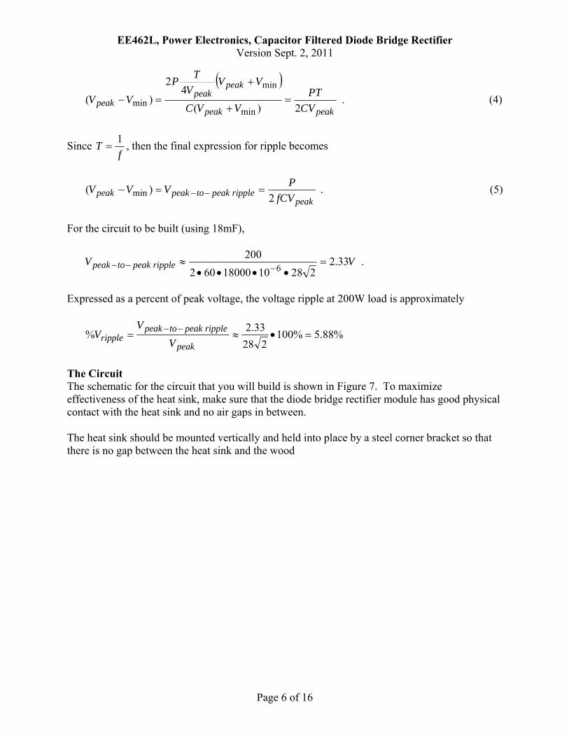
At this point, a helpful simplification can be made if, as shown in Figure 6, the following assumptions are made: 1. the AC sinewave of voltage is approximated as a triangular wave, and 2. a straight line decay of voltage. In that case, simple geometry shows the relationship between tΔ and )( minVVpeak − to be
⎟⎟⎠
⎞⎜⎜⎝
⎛+=•+=Δ
peakpeak VVTT
VVTt minmin 1
444, or
( )min4VV
VTt peakpeak
+=Δ . (3)
Substituting into (3) into (2) yields
Vpeak
Vmin
Δt
T/4 T/4
Figure 6. Approximation of Waveform Used for Ripple Calculation Formula
EE462L, Power Electronics, Capacitor Filtered Diode Bridge Rectifier Version Sept. 2, 2011
Page 6 of 16
( )
peakpeak
peakpeak
peak CVPT
VVC
VVV
TPVV
2)(4
2)(
min
min
min =+
+
=− . (4)
Since f
T 1= , then the final expression for ripple becomes
peakripplepeaktopeakpeak fCV
PVVV2
)( min ==− −− . (5)
For the circuit to be built (using 18mF),
VV ripplepeaktopeak 33.22281018000602
2006 =••••
≈−−− .
Expressed as a percent of peak voltage, the voltage ripple at 200W load is approximately
%88.5%100228
33.2% =•≈= −−
peak
ripplepeaktopeakripple V
VV
The Circuit The schematic for the circuit that you will build is shown in Figure 7. To maximize effectiveness of the heat sink, make sure that the diode bridge rectifier module has good physical contact with the heat sink and no air gaps in between. The heat sink should be mounted vertically and held into place by a steel corner bracket so that there is no gap between the heat sink and the wood
EE462L, Power Electronics, Capacitor Filtered Diode Bridge Rectifier Version Sept. 2, 2011
Page 7 of 16
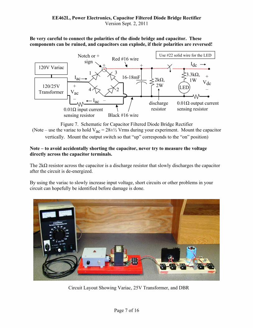
Be very careful to connect the polarities of the diode bridge and capacitor. These components can be ruined, and capacitors can explode, if their polarities are reversed!
Figure 7. Schematic for Capacitor Filtered Diode Bridge Rectifier (Note – use the variac to hold Vac = 28±½ Vrms during your experiment. Mount the capacitor
vertically. Mount the output switch so that “up” corresponds to the “on” position)
Note – to avoid accidentally shorting the capacitor, never try to measure the voltage directly across the capacitor terminals. The 2kΩ resistor across the capacitor is a discharge resistor that slowly discharges the capacitor after the circuit is de-energized. By using the variac to slowly increase input voltage, short circuits or other problems in your circuit can hopefully be identified before damage is done.
Circuit Layout Showing Variac, 25V Transformer, and DBR
+
–
+ Vac
–
1
4
3
2
16-18mFIac 2kΩ, 2W
discharge resistor 0.01Ω input current
sensing resistor
Iac
120/25V
Transformer
120V Variac Idc
+ Vdc
–
Red #16 wire
0.01Ω output current sensing resistor
LED
3.3kΩ, 1W
Notch or + sign
+
Black #16 wire
Use #22 solid wire for the LED
EE462L, Power Electronics, Capacitor Filtered Diode Bridge Rectifier Version Sept. 2, 2011
Page 8 of 16
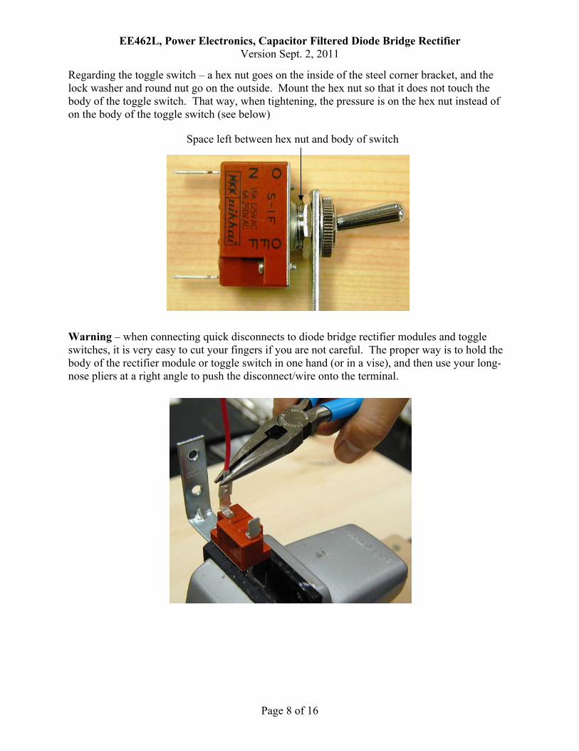
Regarding the toggle switch – a hex nut goes on the inside of the steel corner bracket, and the lock washer and round nut go on the outside. Mount the hex nut so that it does not touch the body of the toggle switch. That way, when tightening, the pressure is on the hex nut instead of on the body of the toggle switch (see below) Warning – when connecting quick disconnects to diode bridge rectifier modules and toggle switches, it is very easy to cut your fingers if you are not careful. The proper way is to hold the body of the rectifier module or toggle switch in one hand (or in a vise), and then use your long-nose pliers at a right angle to push the disconnect/wire onto the terminal.
Space left between hex nut and body of switch
EE462L, Power Electronics, Capacitor Filtered Diode Bridge Rectifier Version Sept. 2, 2011
Page 9 of 16
The Experiment A. No Load Conditions. Connect a 25V transformer to the input of your unloaded DBR. Then,
with a variac turned off and its voltage control knob at zero, plug the 25V transformer into the variac outlet. Slowly raise the variac to a few volts and make sure that the variac current remains zero. Then, slowly raise the variac so that the transformer output is 28±½ Vrms. Use a multimeter to measure the “no load” values of Vac and Vdc. Make sure you measure Vdc at your DBR’s output terminals. View no-load Vac on the oscilloscope. Then, move your oscilloscope probe and view no-load Vdc on the oscilloscope. The ripple voltage should be nearly zero. Note – do not attempt to view Vac and Vdc simultaneously on the oscilloscope because they have different ground reference points!
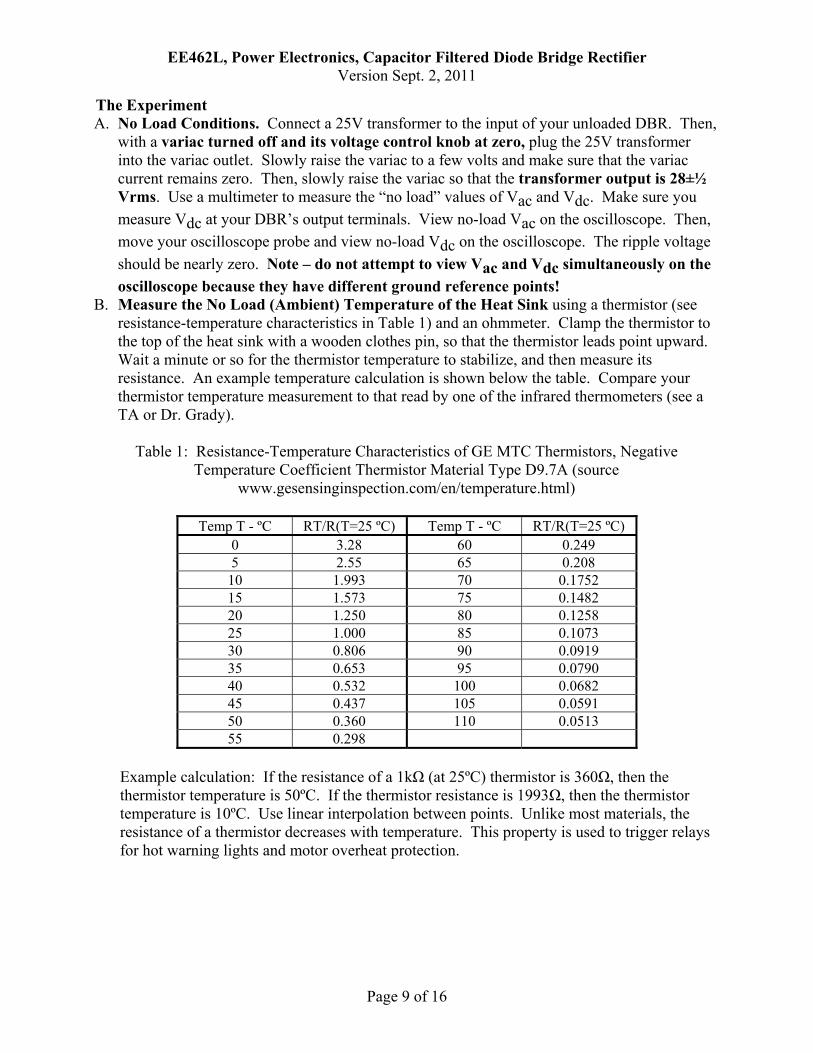
B. Measure the No Load (Ambient) Temperature of the Heat Sink using a thermistor (see resistance-temperature characteristics in Table 1) and an ohmmeter. Clamp the thermistor to the top of the heat sink with a wooden clothes pin, so that the thermistor leads point upward. Wait a minute or so for the thermistor temperature to stabilize, and then measure its resistance. An example temperature calculation is shown below the table. Compare your thermistor temperature measurement to that read by one of the infrared thermometers (see a TA or Dr. Grady).
Table 1: Resistance-Temperature Characteristics of GE MTC Thermistors, Negative
Temperature Coefficient Thermistor Material Type D9.7A (source www.gesensinginspection.com/en/temperature.html)
Temp T - ºC RT/R(T=25 ºC) Temp T - ºC RT/R(T=25 ºC)
0 3.28 60 0.249 5 2.55 65 0.208
10 1.993 70 0.1752 15 1.573 75 0.1482 20 1.250 80 0.1258 25 1.000 85 0.1073 30 0.806 90 0.0919 35 0.653 95 0.0790 40 0.532 100 0.0682 45 0.437 105 0.0591 50 0.360 110 0.0513 55 0.298
Example calculation: If the resistance of a 1kΩ (at 25ºC) thermistor is 360Ω, then the thermistor temperature is 50ºC. If the thermistor resistance is 1993Ω, then the thermistor temperature is 10ºC. Use linear interpolation between points. Unlike most materials, the resistance of a thermistor decreases with temperature. This property is used to trigger relays for hot warning lights and motor overheat protection.
EE462L, Power Electronics, Capacitor Filtered Diode Bridge Rectifier Version Sept. 2, 2011
Page 10 of 16
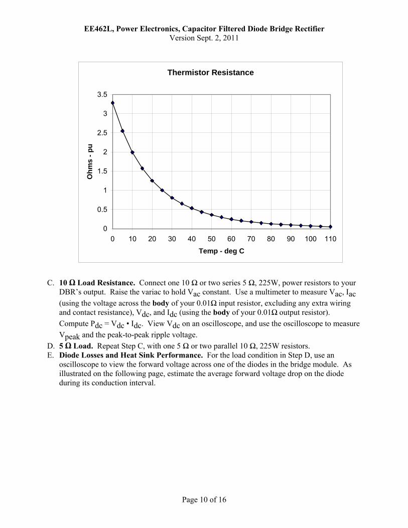
C. 10 Ω Load Resistance. Connect one 10 Ω or two series 5 Ω, 225W, power resistors to your
DBR’s output. Raise the variac to hold Vac constant. Use a multimeter to measure Vac, Iac (using the voltage across the body of your 0.01Ω input resistor, excluding any extra wiring and contact resistance), Vdc, and Idc (using the body of your 0.01Ω output resistor). Compute Pdc = Vdc • Idc. View Vdc on an oscilloscope, and use the oscilloscope to measure Vpeak and the peak-to-peak ripple voltage.
D. 5 Ω Load. Repeat Step C, with one 5 Ω or two parallel 10 Ω, 225W resistors. E. Diode Losses and Heat Sink Performance. For the load condition in Step D, use an
oscilloscope to view the forward voltage across one of the diodes in the bridge module. As illustrated on the following page, estimate the average forward voltage drop on the diode during its conduction interval.
Thermistor Resistance
0
0.5
1
1.5
2
2.5
3
3.5
0 10 20 30 40 50 60 70 80 90 100 110
Temp - deg C
Ohm
s - p
u
EE462L, Power Electronics, Capacitor Filtered Diode Bridge Rectifier Version Sept. 2, 2011
Page 11 of 16
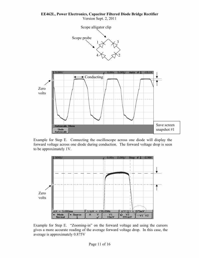
Example for Step E. Connecting the oscilloscope across one diode will display the forward voltage across one diode during conduction. The forward voltage drop is seen to be approximately 1V.
Zero volts
Conducting
Save screen snapshot #1
Example for Step E. “Zooming-in” on the forward voltage and using the cursors gives a more accurate reading of the average forward voltage drop. In this case, the average is approximately 0.875V
Zero volts
1
4
3
2
Scope probe
Scope alligator clip
EE462L, Power Electronics, Capacitor Filtered Diode Bridge Rectifier Version Sept. 2, 2011
Page 12 of 16
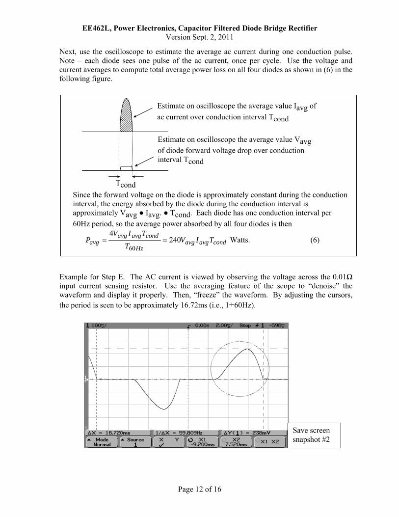
Next, use the oscilloscope to estimate the average ac current during one conduction pulse. Note – each diode sees one pulse of the ac current, once per cycle. Use the voltage and current averages to compute total average power loss on all four diodes as shown in (6) in the following figure.
Example for Step E. The AC current is viewed by observing the voltage across the 0.01Ω input current sensing resistor. Use the averaging feature of the scope to “denoise” the waveform and display it properly. Then, “freeze” the waveform. By adjusting the cursors, the period is seen to be approximately 16.72ms (i.e., 1÷60Hz).
Save screen snapshot #2
Estimate on oscilloscope the average value Iavg of ac current over conduction interval Tcond
Tcond
Estimate on oscilloscope the average value Vavg of diode forward voltage drop over conduction interval Tcond
Since the forward voltage on the diode is approximately constant during the conduction interval, the energy absorbed by the diode during the conduction interval is approximately Vavg Iavg. Tcond. Each diode has one conduction interval per 60Hz period, so the average power absorbed by all four diodes is then
condavgavgHz
condavgavgavg TIV
TTIV
P 2404
60== Watts. (6)
EE462L, Power Electronics, Capacitor Filtered Diode Bridge Rectifier Version Sept. 2, 2011
Page 13 of 16
One pulse of the AC current passes through each diode pair. In the example shown above, the peak of the voltage pulse across the 0.01Ω current shunt is 238mV, corresponding to 0.238V÷0.01 = 23.8A. The conduction time is 4.68ms. Because the pulse is approximately triangular, the average value during conduction is about 23.8÷2 = 11.9A. A handy fact to remember is that with a 0.01Ω current shunt, 10mV corresponds to 1A. After the circuit has been operating with the 5Ω load for at least five minutes, use a thermistor to measure the temperature of the heat sink. Compute the ºC rise above ambient (note – ambient temperature was measured in Step B). Use the power loss from (6) and the temperature rise to compute the thermal resistance coefficient of the heat sink (in ºC rise per Watt). The manufacturer’s catalog thermal resistance value is approximately 2ºC/W. Compare your thermistor temperature measurement to that shown by one of the infrared thermometers.
F. Plot Idc vs. Vdc for Steps A, C, and D. Put Idc on the vertical axis, and Vdc on the horizontal axis.
G. Plot Measured %Vripple for Steps A, C, and D. Put %Vripple on the vertical axis, and Pdc on the horizontal axis.
H. Plot Theoretical %Vripple for Steps A, C, and D. Use (5) with the measured values of Vpeak and P (i.e., P = Vdc • Idc). Superimpose the results of (5) on the plot from Step G.
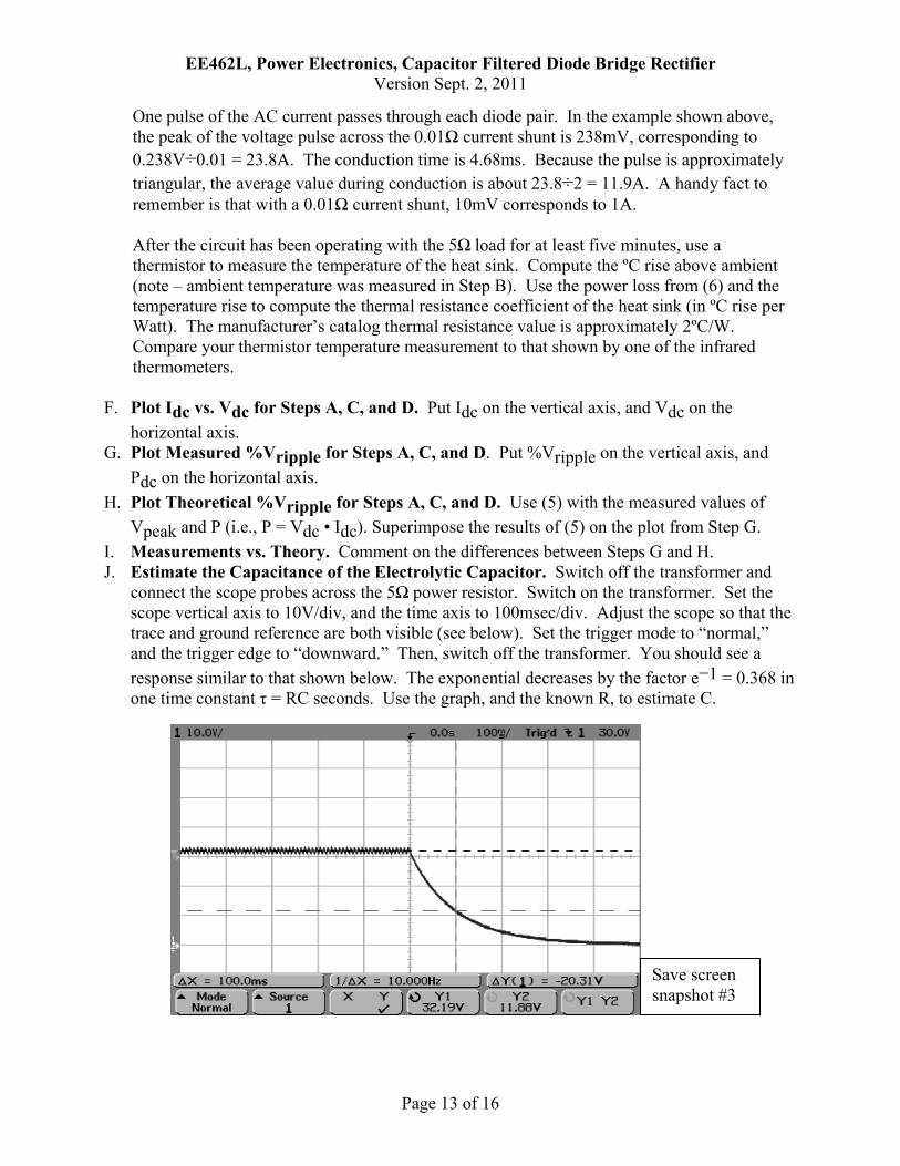
I. Measurements vs. Theory. Comment on the differences between Steps G and H. J. Estimate the Capacitance of the Electrolytic Capacitor. Switch off the transformer and
connect the scope probes across the 5Ω power resistor. Switch on the transformer. Set the scope vertical axis to 10V/div, and the time axis to 100msec/div. Adjust the scope so that the trace and ground reference are both visible (see below). Set the trigger mode to “normal,” and the trigger edge to “downward.” Then, switch off the transformer. You should see a response similar to that shown below. The exponential decreases by the factor e−1 = 0.368 in one time constant τ = RC seconds. Use the graph, and the known R, to estimate C.
Save screen snapshot #3
EE462L, Power Electronics, Capacitor Filtered Diode Bridge Rectifier Version Sept. 2, 2011
Page 14 of 16
Parts List • Five 2-terminal, 30A terminal blocks (Molex/Beau, Mouser #538-38211-0102) • 200V, 35A diode bridge rectifier module (Vishay Semiconductor, Mouser #625-GBPC3502-
E4), (note + and – terminals, and be careful with polarity!) • One 3” by 4” heat sink (Wakefield 641K, Mouser #567-641-K, or DigiKey # 345-1053-ND).
2ºC per Watt. Hole drilled with 5/32” bit, and de-burred to smooth surface, to fit 1½” steel corner bracket.
• 18000µF, 50V Mallory computer-grade electrolytic capacitor (Mouser #539-CGS50V18000), with screws and lockwashers (note + and – terminals, and be careful with polarity!). Alternatively, use 16000µF, 50V capacitors.
• Vertical mounting clamp with tightening screw for capacitor (For 18,000µF, use Mallory VR8, Mouser #539-VR8; for 16,000µF, use Mallory VR3, Mouser #539-VR3), or equivalent. (Clamp uses #6-32 x ½” to 1” machine screw and nut)
• Toggle switch, SPST, 125V, 15A with quick connect terminals (Mouser #633-S1F-RO) • GE NTC thermistors, 1kΩ at 25ºC (Mouser #527-2004-1K). Alternately, use 500Ω or 2kΩ. • Wooden clothes pin to hold the thermistor firmly against heat sink fins to make a good
thermal contact. • LED indicator light and assembly, T-1¾ (5mm), approx. 10ma (Mouser #358-R9-104L-12-
R) • 1½” steel corner bracket for mounting the heat sink (Stanley 30-3170, Home Depot). • 2” steel corner bracket for mounting the switch (Stanley 30-3300, Home Depot). Hole in
bracket enlarged with 15/32” drill bit to fit the toggle switch. • 1” steel corner bracket for mounting LED. Hole in bracket enlarged with 5/16” drill bit to fit
the LED indicator assembly. • Two 0.01Ω, 3W metal element current sensing resistors (IRC Advanced Film Division,
Mouser #66-LOB3R010JLF), or (Ohmite, Digikey #630HR010-ND) (in student parts bin) • 2kΩ, 2W resistor (in student parts bin) • 3.3kΩ, 1W resistor (in student parts bin) • 1” x 6” wood (approx. 12” long piece)
EE462L, Power Electronics, Capacitor Filtered Diode Bridge Rectifier Version Sept. 2, 2011
Page 15 of 16
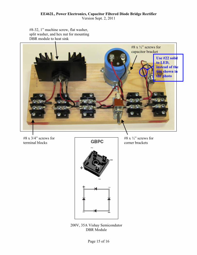
200V, 35A Vishay Semicondutor DBR Module
#8 x ½” screws for corner brackets
#8 x ½” screws for capacitor bracket
#8-32, 1” machine screw, flat washer, split washer, and hex nut for mounting DBR module to heat sink
#8 x 3/4” screws for terminal blocks
Use #22 solid to LED, instead of the #16 shown in the photo
EE462L, Power Electronics, Capacitor Filtered Diode Bridge Rectifier Version Sept. 2, 2011
Page 16 of 16
Solar Panel Temp
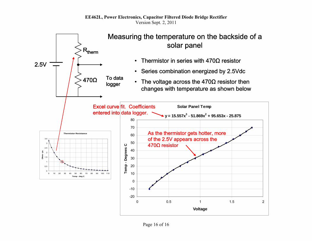
y = 15.557x3 - 51.869x2 + 95.653x - 25.875
-20
-10
0
10
20
30
40
50
60
70
80
0 0.5 1 1.5 2
Voltage
Tem
p - D
egre
es C
• Thermistor in series with 470Ω resistor
• Series combination energized by 2.5Vdc
• The voltage across the 470Ω resistor then changes with temperature as shown below
470Ω
Rtherm
2.5V
To data logger
As the thermistor gets hotter, more of the 2.5V appears across the 470Ω resistor
Excel curve fit. Coefficients entered into data logger.
Thermistor Resistance
0
0.5
1
1.5
2
2.5
3
3.5
0 10 20 30 40 50 60 70 80 90 100 110
Temp - deg C
Ohm
s - p
u
Measuring the temperature on the backside of a solar panel
Solar Panel Temp
y = 15.557x3 - 51.869x2 + 95.653x - 25.875
-20
-10
0
10
20
30
40
50
60
70
80
0 0.5 1 1.5 2
Voltage
Tem
p - D
egre
es C
• Thermistor in series with 470Ω resistor
• Series combination energized by 2.5Vdc
• The voltage across the 470Ω resistor then changes with temperature as shown below
470Ω
Rtherm
2.5V
To data logger
470Ω
Rtherm
2.5V
To data logger
As the thermistor gets hotter, more of the 2.5V appears across the 470Ω resistor
As the thermistor gets hotter, more of the 2.5V appears across the 470Ω resistor
Excel curve fit. Coefficients entered into data logger.Excel curve fit. Coefficients entered into data logger.
Thermistor Resistance
0
0.5
1
1.5
2
2.5
3
3.5
0 10 20 30 40 50 60 70 80 90 100 110
Temp - deg C
Ohm
s - p
u
Thermistor Resistance
0
0.5
1
1.5
2
2.5
3
3.5
0 10 20 30 40 50 60 70 80 90 100 110
Temp - deg C
Ohm
s - p
u
Measuring the temperature on the backside of a solar panel