Embed Size (px)
Citation preview
EEL5666C: IMDL
Summer 2002
Mappie
Final Report
August 13, 2002 Michael Pusatera
1. Table of Contents 1. Table of Contents........................................................................................................ 1 2. Table of Figures .......................................................................................................... 2 3. Abstract ....................................................................................................................... 2 4. Executive Summary.................................................................................................... 3 5. Introduction................................................................................................................. 3 6. Integrated System........................................................................................................ 4 7. Mobile Platform.......................................................................................................... 6 8. Actuation..................................................................................................................... 7 9. Sensors ........................................................................................................................ 7
9.1. Bump Sensors ..................................................................................................... 7 9.1.1. Sensor Design ............................................................................................. 7 9.1.2. Implementation ........................................................................................... 8 9.1.3. Use .............................................................................................................. 8 9.1.4. Lessons Learned.......................................................................................... 9
9.2. Infrared Sensors .................................................................................................. 9 9.2.1. Sensor Design ............................................................................................. 9 9.2.2. Implementation ......................................................................................... 10 9.2.3. Use ............................................................................................................ 10 9.2.4. Lessons Learned........................................................................................ 10
9.3. Optical Mice...................................................................................................... 10 9.3.1. Sensor Design ........................................................................................... 11 9.3.2. Implementation ......................................................................................... 13
EEL5666C Intelligent Machine Design Laboratory Page 2/56 Summer 2002 8/13/2002
9.3.3. Lessons Learned........................................................................................ 14 10. Behaviors .............................................................................................................. 14
10.1. Obstacle Avoidance ...................................................................................... 14 10.2. Go Straight .................................................................................................... 16 10.3. Go Straight and Return ................................................................................. 19 10.4. Move in a Square .......................................................................................... 21
11. Experimental Layout and Results ......................................................................... 21 12. Conclusion ............................................................................................................ 27 13. Documentation...................................................................................................... 29 14. Appendices............................................................................................................ 29
14.1. Avoid.c .......................................................................................................... 29 14.2. GoReturn.c .................................................................................................... 31 14.3. Square.c......................................................................................................... 37 14.4. Straight.c ....................................................................................................... 43 14.5. Mouse16.vhd[3] ............................................................................................ 48 14.6. Output Controller (memorymapwmice.vhd) ................................................ 53 14.7. Mouse Design ............................................................................................... 56
2. Table of Figures Figure 1. Integrated System............................................................................................ 4 Figure 2. Organizational Flow Chart............................................................................. 5 Figure 3. Bump Switch Design ....................................................................................... 8 Figure 4. Infrared Sensor Design ................................................................................... 9 Figure 5. How Optical Mouse Works [2] ..................................................................... 10 Figure 6. Mouse State Machine [3].............................................................................. 11 Figure 7. Data Stream Format [2] ............................................................................... 12 Figure 8. Optical Mouse Design................................................................................... 13 Figure 9. Obstacle Avoidance Algorithm ..................................................................... 15 Figure 10. Go Straight Algorithm............................................................................... 16 Figure 11. Mouse fading left....................................................................................... 17 Figure 12. Agent Fading Left with Correction........................................................... 18 Figure 13. Straight and Turn Movement .................................................................... 19 Figure 14. Arc formulations ....................................................................................... 20 Figure 15. Path for Movement in a Square ................................................................ 21 Figure 16. Position and speed – 2 feet ....................................................................... 22 Figure 17. Change in speed – 2 feet ........................................................................... 23 Figure 18. Position and speed – 3 feet ....................................................................... 24 Figure 19. Change in speed – 3 feet ........................................................................... 25 Figure 20. Position and speed – 4 feet ....................................................................... 26 Figure 21. Change in speed – 4 feet ........................................................................... 27 3. Abstract The world of robotics is a rapidly expanding technology. It is a frontier today, much the way personal computing was twenty-years ago. The creation of autonomous mobile robotics in the last decade has created a universe of opportunity for robotic solutions to an infinite number of tasks.

EEL5666C Intelligent Machine Design Laboratory Page 3/56 Summer 2002 8/13/2002
This autonomous robot is modeled after the Talrik style robots designed at the University of Florida in the mid to late 1990’s. It is designed to utilize optical mice as a tool for navigation. The mice will allow the robot to determine distance traveled without the errors associated with stepping motors and optical encoders. 4. Executive Summary The robotics project for this class is a two wheeled circular robot designed to navigate using optical mice. Since the early 1990’s robotics classes at the University of Florida have seen projects attempting so successfully navigate mazes and map a room. This is increasingly difficult without the use of expensive motors because the servos typically used do not have linear speed controls and do not operate at the same speed in both directions. This robot is designed to utilize a non-mechanical method of distance sensing so as to eliminate the kinds of errors associated with stepper motors and optical encoders. These previous designs suffer from errors due to slippage of the wheels on the surface the robot runs on. This will not be a problem with the optical mice as the mice do not require the wheels for measurement. The agent should be designed to support the electronics required to operate the mice and the servos needed to move the platform. The agent should be able to move around a maze or room and take measurements of the room and objects in it. This will be accomplished by coordinating the optical mice and infrared sensors to determine the length of walls and the perimeters of objects in the room and the exterior of the room the robot operates in. 5. Introduction As an engineer very interested in the practical application of the trade, I decided to try to use my experience in this lab as a building block upon which future students would be able to build. I wanted to work on a project which would be challenging and provide a new insight into a problem that has remained unsolved in the laboratory. Because my experience has shown that I am not mechanically gifted as an engineer, I also sought to choose a project with the least room for mechanical error. I believed when I began this course that I had found such a project. I intended to build upon the work of Ty Black in IMDL’s Spring 2002 class. The idea was to use two optical mice as a distance sensor to map an environment such as a maze or a room. Because the mice were self contained, I assumed they would not cause any mechanical difficulties and I intended to attach them to the bottom of a robot platform. This would fulfill my requirements for my purpose in this course. This paper will outline the overall structure of the system. It will discuss the platform design and limitations. It will discuss actuation and sensors, detailing expectations and limitations. It will finally discuss behaviors implemented and show results from the
EEL5666C Intelligent Machine Design Laboratory Page 4/56 Summer 2002 8/13/2002
running robot. Finally, conclusions will be drawn and suggestions for future work will be made. 6. Integrated System
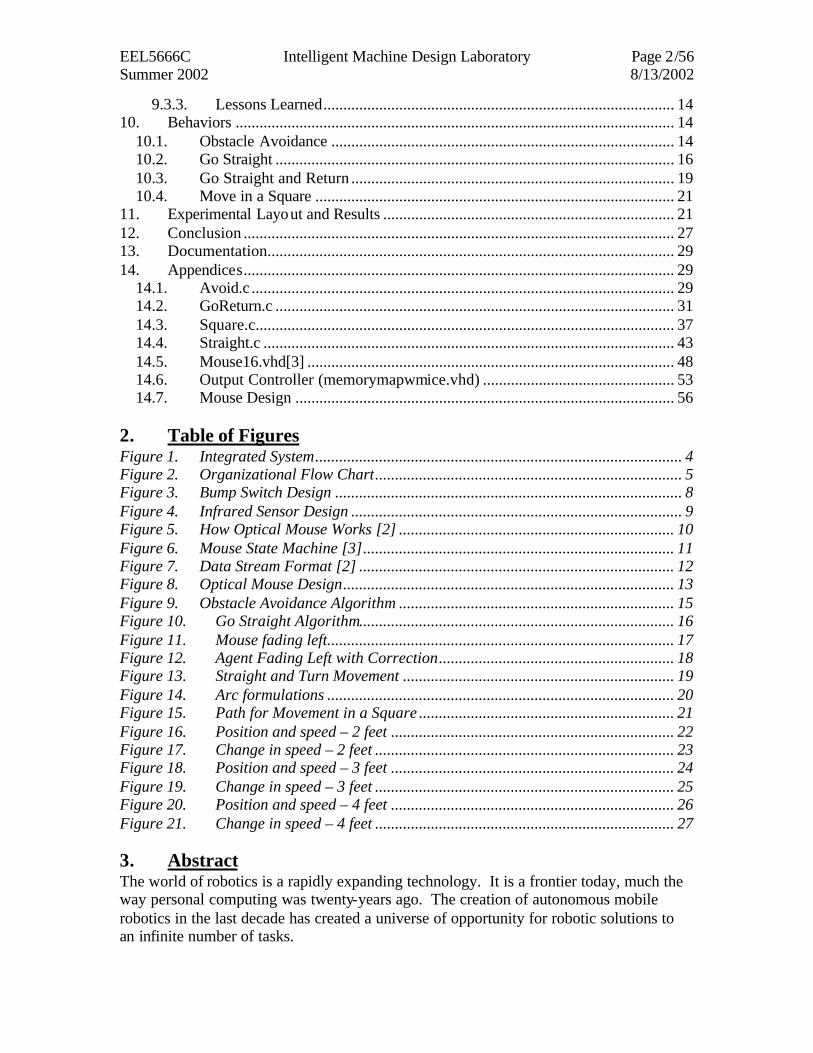
Figure 1. Integrated System
The system is designed to use the data gathered by the optical mice as a tool for navigation. The optical mice provide accurate distance measurements which are critical for navigation. The two mice are interfaced to the microcontroller through the Flex 10k FPGA. This programmable logic device allows the mice to receive the required data inputs for operation. It also formats the data in single byte segments for memory map reading by the microcontroller. The microcontroller will use the data provided by the mice, infrared sensors, and bump network to determine its surroundings and can control the servos in an appropriate manner.
Optical Mouse
Optical Mouse
Left Servo
Right Servo
Bump Sensor
IR Sensors
EVBU Evaluation Board
Motorolla 68HC11
COM to PC
UP1 Education Board
Flex 10k FPGA
JTAG Interface
PC
EEL5666C Intelligent Machine Design Laboratory Page 5/56 Summer 2002 8/13/2002
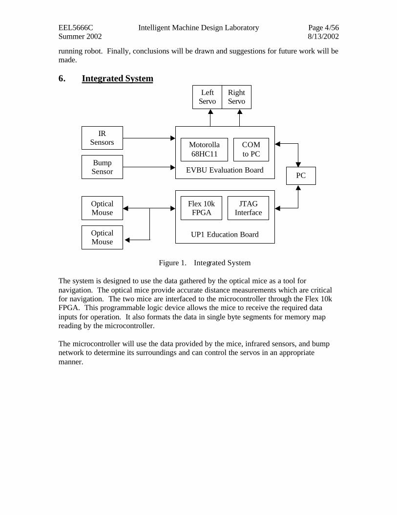
Figure 2. Organizational Flow Chart
The system will operate as pictured in Figure 2. The four sensors on board will be read and analyzed. If an obstacle is detected, it will be avoided by causing the servos to change direction to an appropriate heading. If there is no obstacle, the agent will continue to navigate the environment recording positional measurements from the optical mice. The system is controlled by the Motorola 68HC11 microcontroller. This microcontroller is easy to use and many resources are available for it. It contains 8 analog-to-digital converters on Port E, which were used for infrared and bump sensors. It also contains timer hardware on Port A used to create PWM waveforms for driving the servos. These are input capture and output compare functions. The output compare function was used to generate the PWM waveform needed to drive the servos. The 68HC11 is mounted on the EVBU board which can be purchased for approximately $60. The board contains a serial interface for communication with the COM port on a PC. This is used to program the chip. An expansion area is also available on the board.
yes
no
Read Mouse 1
Read Mouse 1
Read IR Sensors
Read Bump
Network
Obstactle Obstacle Avoidance
Continue Navigation
EEL5666C Intelligent Machine Design Laboratory Page 6/56 Summer 2002 8/13/2002
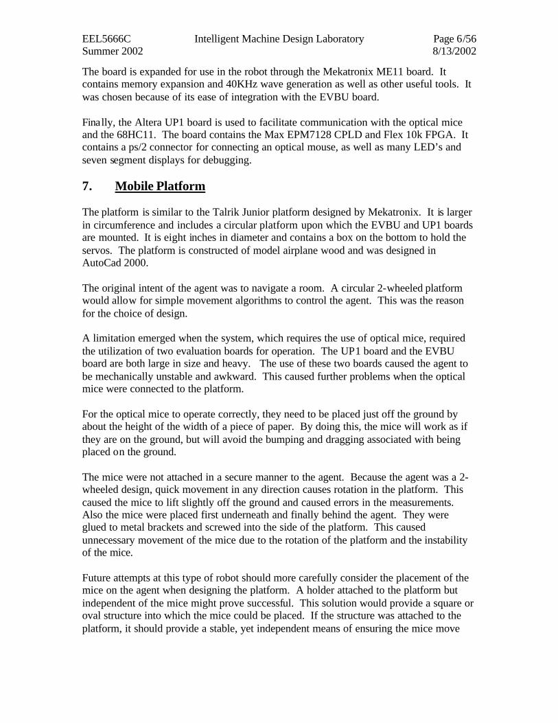
The board is expanded for use in the robot through the Mekatronix ME11 board. It contains memory expansion and 40KHz wave generation as well as other useful tools. It was chosen because of its ease of integration with the EVBU board. Finally, the Altera UP1 board is used to facilitate communication with the optical mice and the 68HC11. The board contains the Max EPM7128 CPLD and Flex 10k FPGA. It contains a ps/2 connector for connecting an optical mouse, as well as many LED’s and seven segment displays for debugging. 7. Mobile Platform The platform is similar to the Talrik Junior platform designed by Mekatronix. It is larger in circumference and includes a circular platform upon which the EVBU and UP1 boards are mounted. It is eight inches in diameter and contains a box on the bottom to hold the servos. The platform is constructed of model airplane wood and was designed in AutoCad 2000. The original intent of the agent was to navigate a room. A circular 2-wheeled platform would allow for simple movement algorithms to control the agent. This was the reason for the choice of design. A limitation emerged when the system, which requires the use of optical mice, required the utilization of two evaluation boards for operation. The UP1 board and the EVBU board are both large in size and heavy. The use of these two boards caused the agent to be mechanically unstable and awkward. This caused further problems when the optical mice were connected to the platform. For the optical mice to operate correctly, they need to be placed just off the ground by about the height of the width of a piece of paper. By doing this, the mice will work as if they are on the ground, but will avoid the bumping and dragging associated with being placed on the ground. The mice were not attached in a secure manner to the agent. Because the agent was a 2-wheeled design, quick movement in any direction causes rotation in the platform. This caused the mice to lift slightly off the ground and caused errors in the measurements. Also the mice were placed first underneath and finally behind the agent. They were glued to metal brackets and screwed into the side of the platform. This caused unnecessary movement of the mice due to the rotation of the platform and the instability of the mice. Future attempts at this type of robot should more carefully consider the placement of the mice on the agent when designing the platform. A holder attached to the platform but independent of the mice might prove successful. This solution would provide a square or oval structure into which the mice could be placed. If the structure was attached to the platform, it should provide a stable, yet independent means of ensuring the mice move
EEL5666C Intelligent Machine Design Laboratory Page 7/56 Summer 2002 8/13/2002
laterally with the agent. It would prevent any fish-tailing that sometimes occurred during turning in this design. 8. Actuation Any mobile robot requires a means of movement. This robot is required to move in a straight line and make accurate turns. It will perform this task via two wheels attached to two servo motors. These motors are simple to interface to the 68HC11 microprocessor board. Movement requires connection to power and ground and a third line attached to an output compare line from Port A on the 68HC11. Pulse Width Modulation is used to drive these servos. A two wheel design creates an ease of movement that is not available in multi-wheel designs. Turning is simplified from a typical four-wheel design. To turn in one direction, one wheel must be driven forward while the other is driven in reverse. Because the movement is simple, this design was chosen to provide few problems in the design process. This met the requirements that the agent be mechanically simple in design so as to reduce the time spent learning to move the agent. The two wheeled design was sufficient for this project. It allowed for simple movement and correct turning. This was accomplished as intended. However, because the platform was designed without correct placement for the mice, the two wheeled design caused problems by rotating the platform and creating an unstable environment for the mice to operate. 9. Sensors 9.1. Bump Sensors Bump sensors are used on the exterior of the robot as a fail safe device to detect impact with objects in the robots path. This sensor is not used when infrared is working properly.
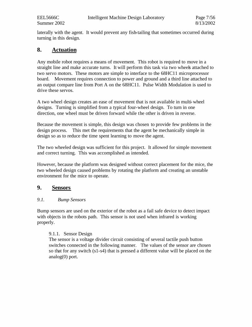
9.1.1. Sensor Design The sensor is a voltage divider circuit consisting of several tactile push button switches connected in the following manner. The values of the sensor are chosen so that for any switch (s1-s4) that is pressed a different value will be placed on the analog(0) port.
EEL5666C Intelligent Machine Design Laboratory Page 8/56 Summer 2002 8/13/2002
Figure 3. Bump Switch Design
9.1.2. Implementation This sensor was implemented using four push button switches and five resistors. The resistor values are:
• R1 = 10k • R2 = 22k • R3 = 47k • R4 = 100k • R5 = 10k
The bump sensors are located at the front, front-right, front- left, and back of the robot. This will ensure that any collisions from forward or reverse motion will be covered by the sensor. 9.1.3. Use The sensor is connected to the analog(0) port of the 68HC11. This requires only that the port be read and appropriate action be taken in response to the data. When
Bump Switch Design
Vcc Vcc Vcc Vcc
R1 R2 R3 R4
Analog(0)
R?
S1 S2 S3 S4
EEL5666C Intelligent Machine Design Laboratory Page 9/56 Summer 2002 8/13/2002
the bump sensor reads a value of 50 the rear bumper has been pushed and the robot will move forward. When the bump sensor reads a value of 80 the right bumper has been activated and the robot will back up and move left. When the bump sensor reads a value of 130 the left bumper has been activated and the robot will back up and move right. When the bump sensor reads a value greater than 130 the front bumper has been activated and the robot will back up, turn in a random direction for a random amount of time and move on. 9.1.4. Lessons Learned
The bump sensors work well. They were implemented quickly and continued to work throughout the project.
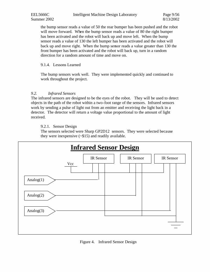
9.2. Infrared Sensors The infrared sensors are designed to be the eyes of the robot. They will be used to detect objects in the path of the robot within a two-foot range of the sensors. Infrared sensors work by sending a pulse of light out from an emitter and receiving the light back in a detector. The detector will return a voltage value proportional to the amount of light received.
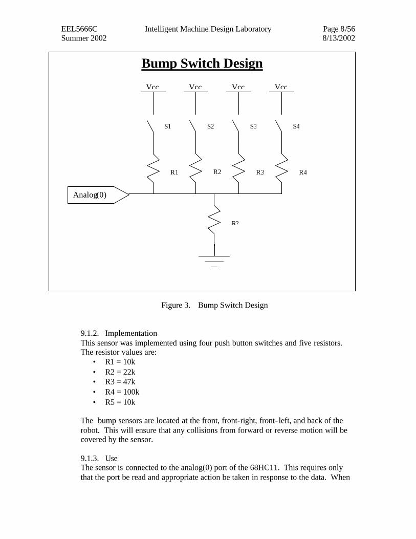
9.2.1. Sensor Design The sensors selected were Sharp GP2D12 sensors. They were selected because they were inexpensive (~$15) and readily available.
Figure 4. Infrared Sensor Design
Infrared Sensor Design
Analog(2)
Analog(3)
Analog(1)
IR Sensor IR Sensor IR Sensor Vcc
EEL5666C Intelligent Machine Design Laboratory Page 10/56 Summer 2002 8/13/2002
9.2.2. Implementation The sensor was remarkably simple to implement. As Figure 4 suggests there are only three lines in the system.
• Vcc: connected to a regulated power supply • Gnd: connected to system ground • Analog(x): connected to the appropriate analog port
The three sensors were placed in the front, front-right, and front- left portion of the robot. This will allow the robot to “see” any objects in its path as well as objects near its sides.
9.2.3. Use The three sensors are connected to the analog(1-3) ports on the 68HC11. The program which controls the sensors will read each sensor and modify behavior based on its result. When the sensors read a value greater than 120 there is an object within one foot of the robot. When the front sensor is activated the robot will turn for a random amount of time in a random direction. When the front-right sensor is activated the robot will turn left for a random amount of time. Similarly, when the front- left sensor is activated the robot will turn right for a random amount of time.
9.2.4. Lessons Learned The infrared sensors were quickly implemented. They worked throughout the project. There was one problem which occurred about a month before the end of the project. When reassembling the platform, the sensors were reconnected backwards causing the power and data pins to be switched. The infrared sensors were replaced after that and a keyed pinout was used to prevent further problems.
9.3. Optical Mice
Figure 5. How Optical Mouse Works [2]
EEL5666C Intelligent Machine Design Laboratory Page 11/56 Summer 2002 8/13/2002
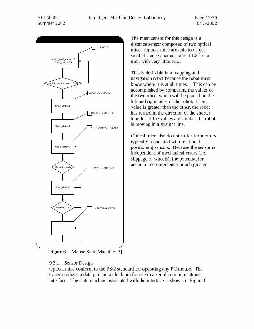
Figure 6. Mouse State Machine [3]
The main sensor for this design is a distance sensor composed of two optical mice. Optical mice are able to detect small distance changes, about 1/8th of a mm, with very little error This is desirable in a mapping and navigation robot because the robot must know where it is at all times. This can be accomplished by comparing the values of the two mice, which will be placed on the left and right sides of the robot. If one value is greater than the other, the robot has turned in the direction of the shorter length. If the values are similar, the robot is moving in a straight line. Optical mice also do not suffer from errors typically associated with relational positioning sensors. Because the sensor is independent of mechanical errors (i.e. slippage of wheels), the potential for accurate measurement is much greater.
9.3.1. Sensor Design Optical mice conform to the PS/2 standard for operating any PC mouse. The system utilizes a data pin and a clock pin for use in a serial communications interface. The state machine associated with the interface is shown in Figure 6.
Inhibit_wait_count +1Char_out = F4
Send_data=1
Inhibit_wait_count [10..9]
Send_data=1
Output_ready
Send_data=0
Send_data=0
IREADY_SET
INHABIT Tx
LOAD COMMAND
LOAD COMMAND 2
WAIT OUTPUT READY
WAIT CMD ACK
INPUT PACKETS
MOUSE STATE MACHINE
EEL5666C Intelligent Machine Design Laboratory Page 12/56 Summer 2002 8/13/2002
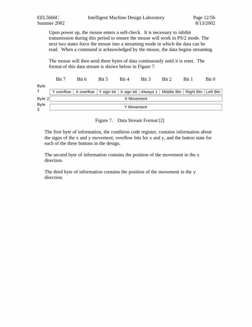
Upon power up, the mouse enters a self-check. It is necessary to inhibit transmission during this period to ensure the mouse will work in PS/2 mode. The next two states force the mouse into a streaming mode in which the data can be read. When a command is acknowledged by the mouse, the data begins streaming. The mouse will then send three bytes of data continuously until it is reset. The format of this data stream is shown below in Figure 7.
Byte 1
Bit 7 Bit 6 Bit 5 Bit 4 Bit 3 Bit 2 Bit 1 Bit 0
Y overflow X overflow Y sign bit X sign bit Always 1 Middle Btn Right Btn Left Btn Byte 2 X Movement Byte 3 Y Movement
Figure 7. Data Stream Format [2]
The first byte of information, the condition code register, contains information about the signs of the x and y movement, overflow bits for x and y, and the button state for each of the three buttons in the design. The second byte of information contains the position of the movement in the x direction. The third byte of information contains the position of the movement in the y direction.
EEL5666C Intelligent Machine Design Laboratory Page 13/56 Summer 2002 8/13/2002
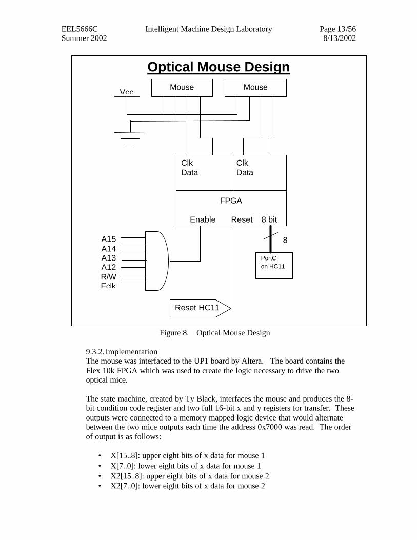
Figure 8. Optical Mouse Design
9.3.2. Implementation The mouse was interfaced to the UP1 board by Altera. The board contains the Flex 10k FPGA which was used to create the logic necessary to drive the two optical mice. The state machine, created by Ty Black, interfaces the mouse and produces the 8-bit condition code register and two full 16-bit x and y registers for transfer. These outputs were connected to a memory mapped logic device that would alternate between the two mice outputs each time the address 0x7000 was read. The order of output is as follows:
• X[15..8]: upper eight bits of x data for mouse 1 • X[7..0]: lower eight bits of x data for mouse 1 • X2[15..8]: upper eight bits of x data for mouse 2 • X2[7..0]: lower eight bits of x data for mouse 2
Optical Mouse Design Mouse Mouse
Vcc
FPGA
Enable Reset 8 bit
Clk Data
Mouse
Clk Data
Mouse
PortC on HC11
8 A15A14A13A12R/WEclk
Reset HC11
EEL5666C Intelligent Machine Design Laboratory Page 14/56 Summer 2002 8/13/2002
• Y[15..8]: upper eight bits of y data for mouse 1 • Y[7..0]: lower eight bits of y data for mouse 1 • Y2[15..8]: upper eight bits of y data for mouse 2 • Y2[7..0]: lower eight bits of y data for mouse 2 • MCCR: condition code register for mouse 1 • MCCR2: condition code register for mouse 2
Upon reading the outputs into the HC11, the data from the two x and two y inputs are combined for a 16-bit x and y location register for each mouse. Once in the HC11, the data can be manipulated to determine distance and movement.
9.3.3. Lessons Learned The mice were not easy to implement at all. The required timing and signals needed to use the mice are not flexible and require the use of a powerful programmable logic device, the Flex 10k FPGA, to interface to the microcontroller. The mice also do not work correctly if they are not placed correctly in the platform. They require a very specific mechanical layout to work well and consistently. It was not possible under the platform designed for this robot to get consistent data all the time from the mice. However, it was possible to get correct data when the mice were placed gently and weighed down for stability. Also, the mice did not give the same distance accuracy all the time. When only the two evaluation boards were drawing power from the battery pack, the mice were able to record distance at an accuracy of 4500 counts per foot, or 375 counts per inch. However, when the servos were running the accuracy would denigrate and typical results were around 285 counts per inch. This value was not constant and was the cause of significant problems in the behavioral programming of the robot. It is suggested that separate battery packs be used to drive the electronics and the actuators of any future design.
10. Behaviors Because of the limitations of time and my platform, the robot is only able to avoid obstacles, go straight, and turn to an angle. 10.1. Obstacle Avoidance
EEL5666C Intelligent Machine Design Laboratory Page 15/56 Summer 2002 8/13/2002
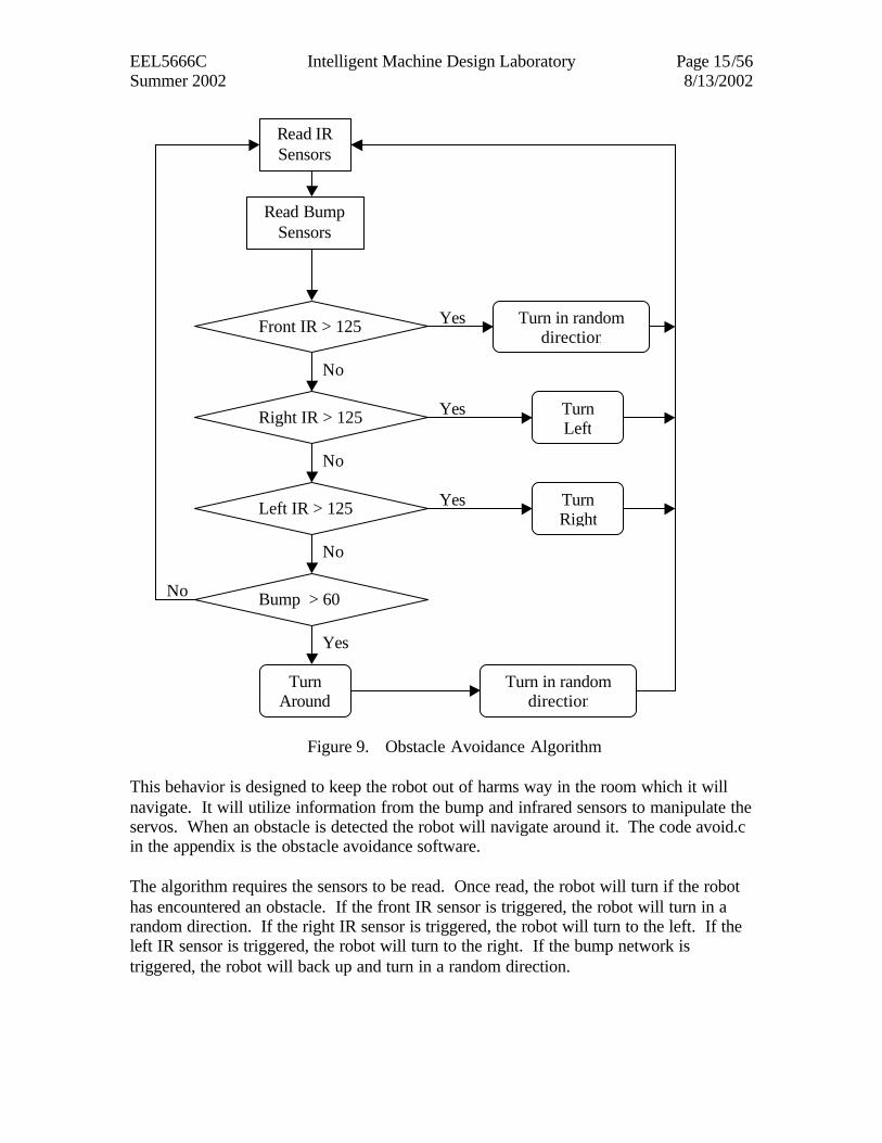
Figure 9. Obstacle Avoidance Algorithm
This behavior is designed to keep the robot out of harms way in the room which it will navigate. It will utilize information from the bump and infrared sensors to manipulate the servos. When an obstacle is detected the robot will navigate around it. The code avoid.c in the appendix is the obstacle avoidance software. The algorithm requires the sensors to be read. Once read, the robot will turn if the robot has encountered an obstacle. If the front IR sensor is triggered, the robot will turn in a random direction. If the right IR sensor is triggered, the robot will turn to the left. If the left IR sensor is triggered, the robot will turn to the right. If the bump network is triggered, the robot will back up and turn in a random direction.
No
No
No
No
Yes
Yes
Yes
Yes
Read IR Sensors
Read Bump Sensors
Right IR > 125
Left IR > 125
Front IR > 125
Bump > 60
Turn in random direction
Turn Left
Turn Right
Turn Around
Turn in random direction
EEL5666C Intelligent Machine Design Laboratory Page 16/56 Summer 2002 8/13/2002
10.2. Go Straight
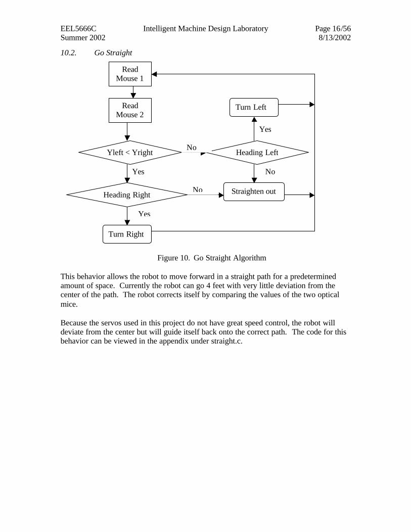
Figure 10. Go Straight Algorithm
This behavior allows the robot to move forward in a straight path for a predetermined amount of space. Currently the robot can go 4 feet with very little deviation from the center of the path. The robot corrects itself by comparing the values of the two optical mice. Because the servos used in this project do not have great speed control, the robot will deviate from the center but will guide itself back onto the correct path. The code for this behavior can be viewed in the appendix under straight.c.
Yes
Yes
Read Mouse 1
Read Mouse 2
Yleft < Yright
Straighten out
Turn Left
Heading Left
Heading Right
Turn Right
Yes
No
No
No
EEL5666C Intelligent Machine Design Laboratory Page 17/56 Summer 2002 8/13/2002
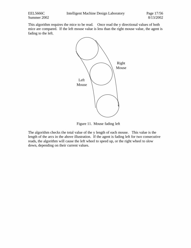
This algorithm requires the mice to be read. Once read the y directional values of both mice are compared. If the left mouse value is less than the right mouse value, the agent is fading to the left.
Figure 11. Mouse fading left
The algorithm checks the total value of the y length of each mouse. This value is the length of the arcs in the above illustration. If the agent is fading left for two consecutive reads, the algorithm will cause the left wheel to speed up, or the right wheel to slow down, depending on their current values.
Right Mouse
Left Mouse
EEL5666C Intelligent Machine Design Laboratory Page 18/56 Summer 2002 8/13/2002
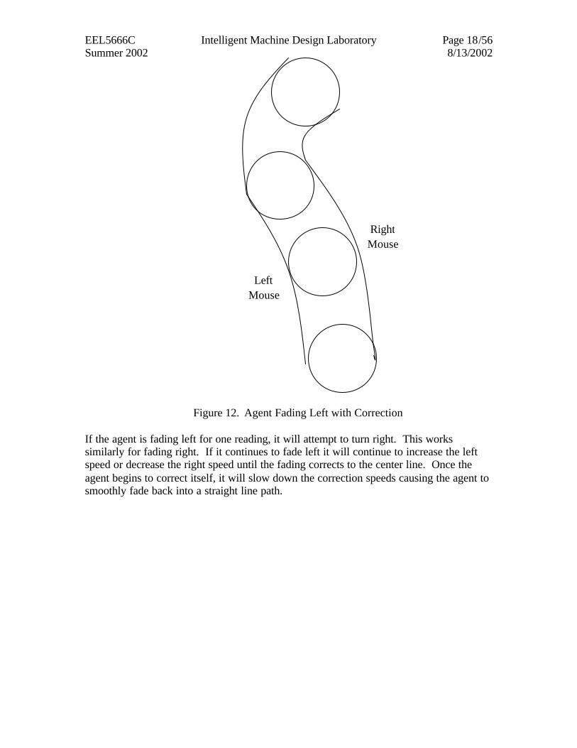
Figure 12. Agent Fading Left with Correction
If the agent is fading left for one reading, it will attempt to turn right. This works similarly for fading right. If it continues to fade left it will continue to increase the left speed or decrease the right speed until the fading corrects to the center line. Once the agent begins to correct itself, it will slow down the correction speeds causing the agent to smoothly fade back into a straight line path.
Right Mouse
Left Mouse
EEL5666C Intelligent Machine Design Laboratory Page 19/56 Summer 2002 8/13/2002
10.3. Go Straight and Return
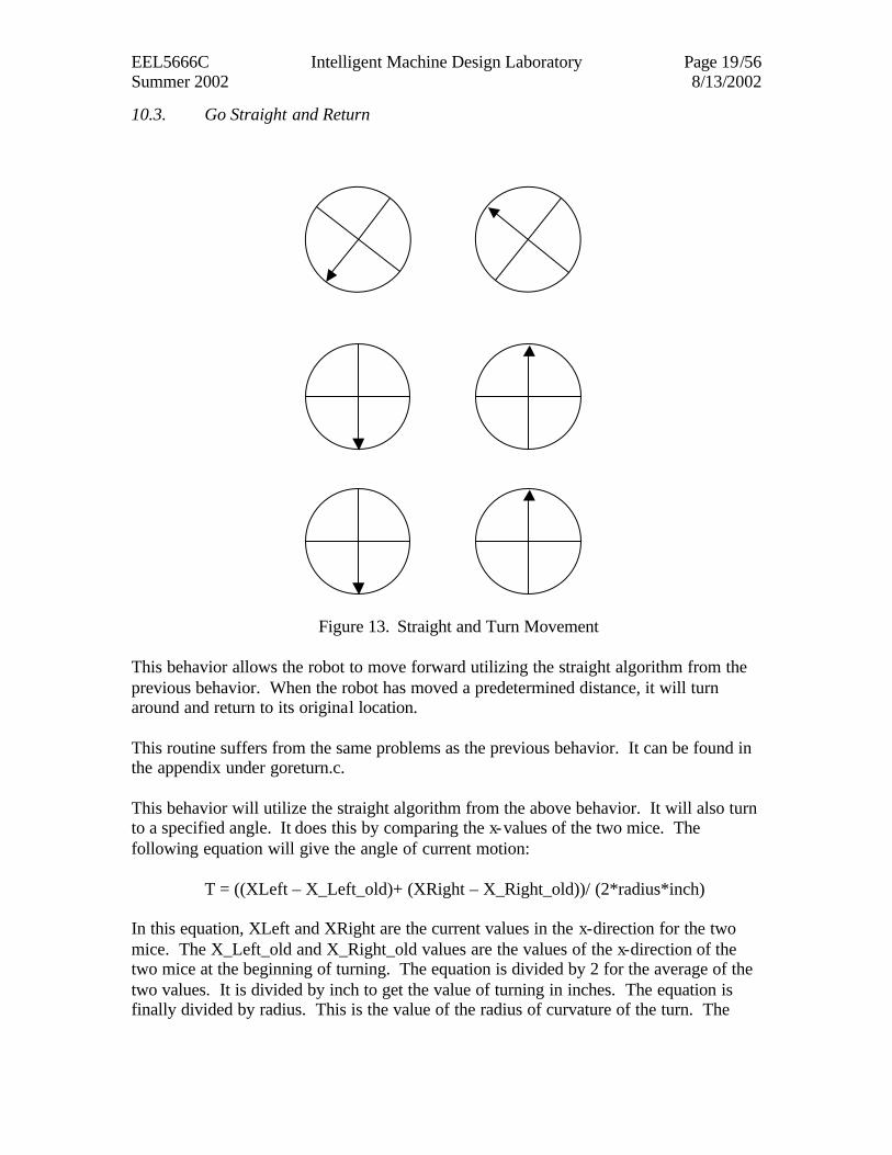
Figure 13. Straight and Turn Movement
This behavior allows the robot to move forward utilizing the straight algorithm from the previous behavior. When the robot has moved a predetermined distance, it will turn around and return to its original location. This routine suffers from the same problems as the previous behavior. It can be found in the appendix under goreturn.c. This behavior will utilize the straight algorithm from the above behavior. It will also turn to a specified angle. It does this by comparing the x-values of the two mice. The following equation will give the angle of current motion:
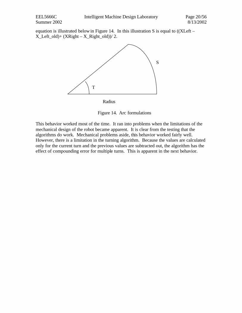
T = ((XLeft – X_Left_old)+ (XRight – X_Right_old))/ (2*radius*inch)
In this equation, XLeft and XRight are the current values in the x-direction for the two mice. The X_Left_old and X_Right_old values are the values of the x-direction of the two mice at the beginning of turning. The equation is divided by 2 for the average of the two values. It is divided by inch to get the value of turning in inches. The equation is finally divided by radius. This is the value of the radius of curvature of the turn. The
EEL5666C Intelligent Machine Design Laboratory Page 20/56 Summer 2002 8/13/2002
equation is illustrated below in Figure 14. In this illustration S is equal to ((XLeft – X_Left_old)+ (XRight – X_Right_old))/ 2.
Figure 14. Arc formulations
This behavior worked most of the time. It ran into problems when the limitations of the mechanical design of the robot became apparent. It is clear from the testing that the algorithms do work. Mechanical problems aside, this behavior worked fairly well. However, there is a limitation in the turning algorithm. Because the values are calculated only for the current turn and the previous values are subtracted out, the algorithm has the effect of compounding error for multiple turns. This is apparent in the next behavior.
Radius
T
S
EEL5666C Intelligent Machine Design Laboratory Page 21/56 Summer 2002 8/13/2002
10.4. Move in a Square
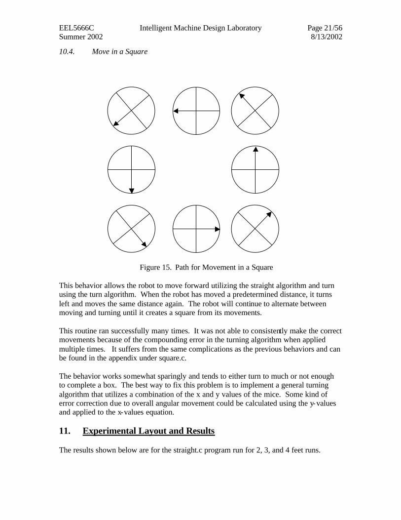
Figure 15. Path for Movement in a Square This behavior allows the robot to move forward utilizing the straight algorithm and turn using the turn algorithm. When the robot has moved a predetermined distance, it turns left and moves the same distance again. The robot will continue to alternate between moving and turning until it creates a square from its movements. This routine ran successfully many times. It was not able to consistently make the correct movements because of the compounding error in the turning algorithm when applied multiple times. It suffers from the same complications as the previous behaviors and can be found in the appendix under square.c. The behavior works somewhat sparingly and tends to either turn to much or not enough to complete a box. The best way to fix this problem is to implement a general turning algorithm that utilizes a combination of the x and y values of the mice. Some kind of error correction due to overall angular movement could be calculated using the y-values and applied to the x-values equation. 11. Experimental Layout and Results The results shown below are for the straight.c program run for 2, 3, and 4 feet runs.
EEL5666C Intelligent Machine Design Laboratory Page 22/56 Summer 2002 8/13/2002
0
1000
2000
3000
4000
5000
6000
7000
8000
1 2 3 4 5 6 7 8 9 10 11 12 13 14 15 16 17 18 19 20
ypos y2pos
leftspeed rightspeed
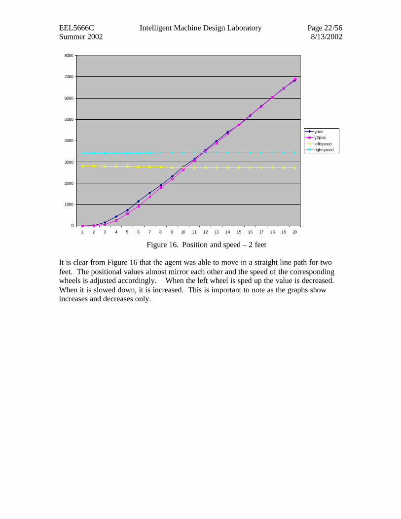
Figure 16. Position and speed – 2 feet
It is clear from Figure 16 that the agent was able to move in a straight line path for two feet. The positional values almost mirror each other and the speed of the corresponding wheels is adjusted accordingly. When the left wheel is sped up the value is decreased. When it is slowed down, it is increased. This is important to note as the graphs show increases and decreases only.
EEL5666C Intelligent Machine Design Laboratory Page 23/56 Summer 2002 8/13/2002
-100
-50
0
50
100
150
200
250
1 2 3 4 5 6 7 8 9 10 11 12 13 14 15 16 17 18 19
time
ydifchange left speed
change right speed
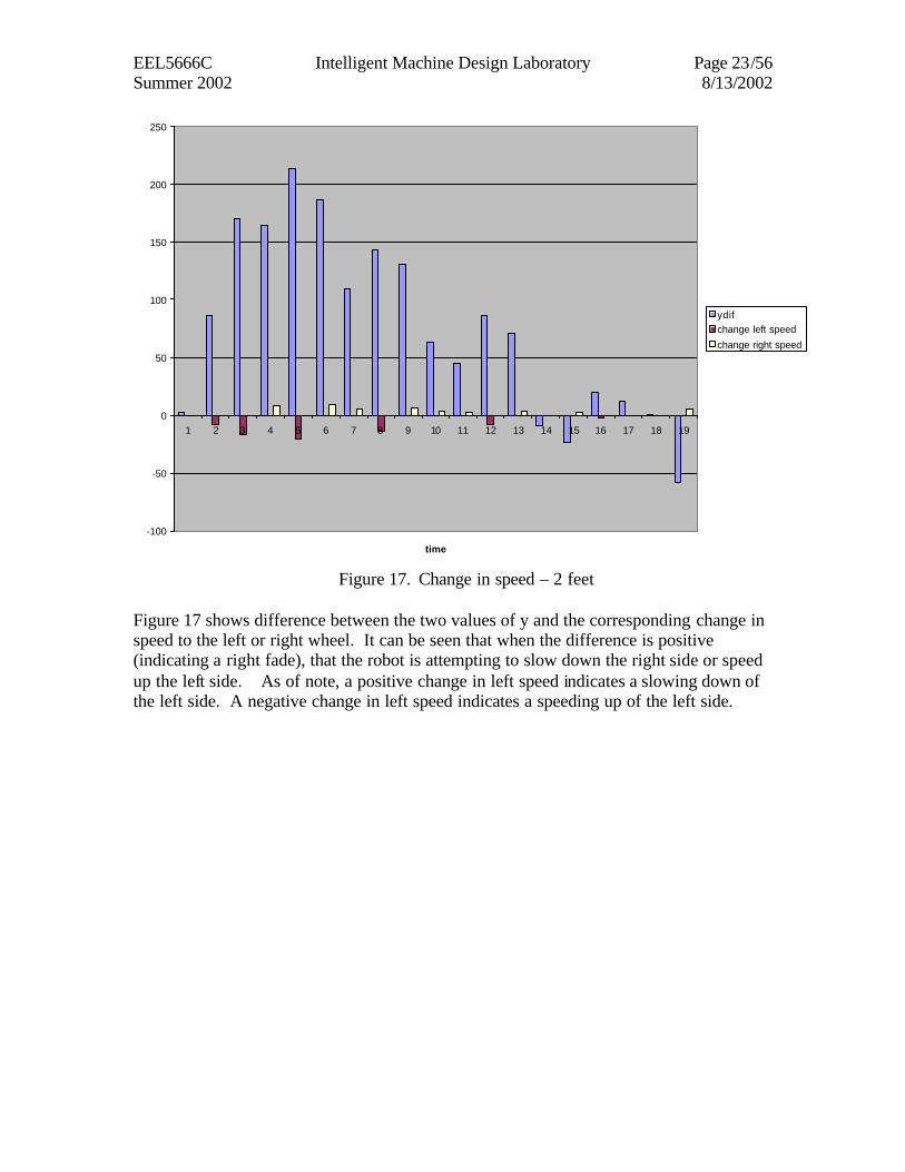
Figure 17. Change in speed – 2 feet
Figure 17 shows difference between the two values of y and the corresponding change in speed to the left or right wheel. It can be seen that when the difference is positive (indicating a right fade), that the robot is attempting to slow down the right side or speed up the left side. As of note, a positive change in left speed indicates a slowing down of the left side. A negative change in left speed indicates a speeding up of the left side.
EEL5666C Intelligent Machine Design Laboratory Page 24/56 Summer 2002 8/13/2002
-2000
0
2000
4000
6000
8000
10000
12000
14000
1 2 3 4 5 6 7 8 9 10 11 12 13 14 15 16 17 18 19 20 21 22 23 24 25 26 27 28 29 30 31 32 33 34
ypos
y2pos leftspeed
rightspeed
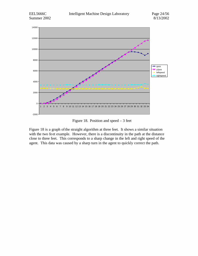
Figure 18. Position and speed – 3 feet
Figure 18 is a graph of the straight algorithm at three feet. It shows a similar situation with the two feet example. However, there is a discontinuity in the path at the distance close to three feet. This corresponds to a sharp change in the left and right speed of the agent. This data was caused by a sharp turn in the agent to quickly correct the path.
EEL5666C Intelligent Machine Design Laboratory Page 25/56 Summer 2002 8/13/2002
-3000
-2500
-2000
-1500
-1000
-500
0
500
1 2 3 4 5 6 7 8 9 10 11 12 13 14 15 16 17 18 19 20 21 22 23 24 25 26 27 28 29 30 31 32 33
time
ydifchange left speedchange right speed
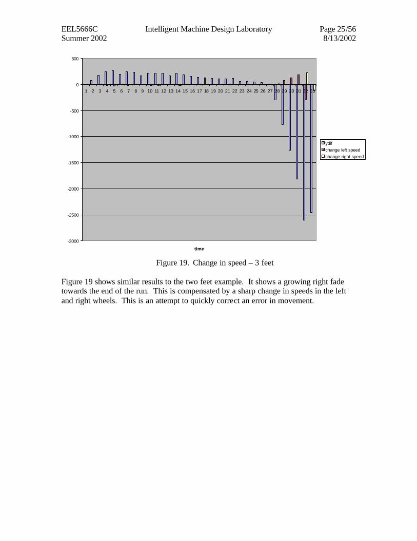
Figure 19. Change in speed – 3 feet
Figure 19 shows similar results to the two feet example. It shows a growing right fade towards the end of the run. This is compensated by a sharp change in speeds in the left and right wheels. This is an attempt to quickly correct an error in movement.
EEL5666C Intelligent Machine Design Laboratory Page 26/56 Summer 2002 8/13/2002
-2000
0
2000
4000
6000
8000
10000
12000
14000
16000
1 3 5 7 9 11 13 15 17 19 21 23 25 27 29 31 33 35 37 39 41 43
ypos
y2pos leftspeed
rightspeed
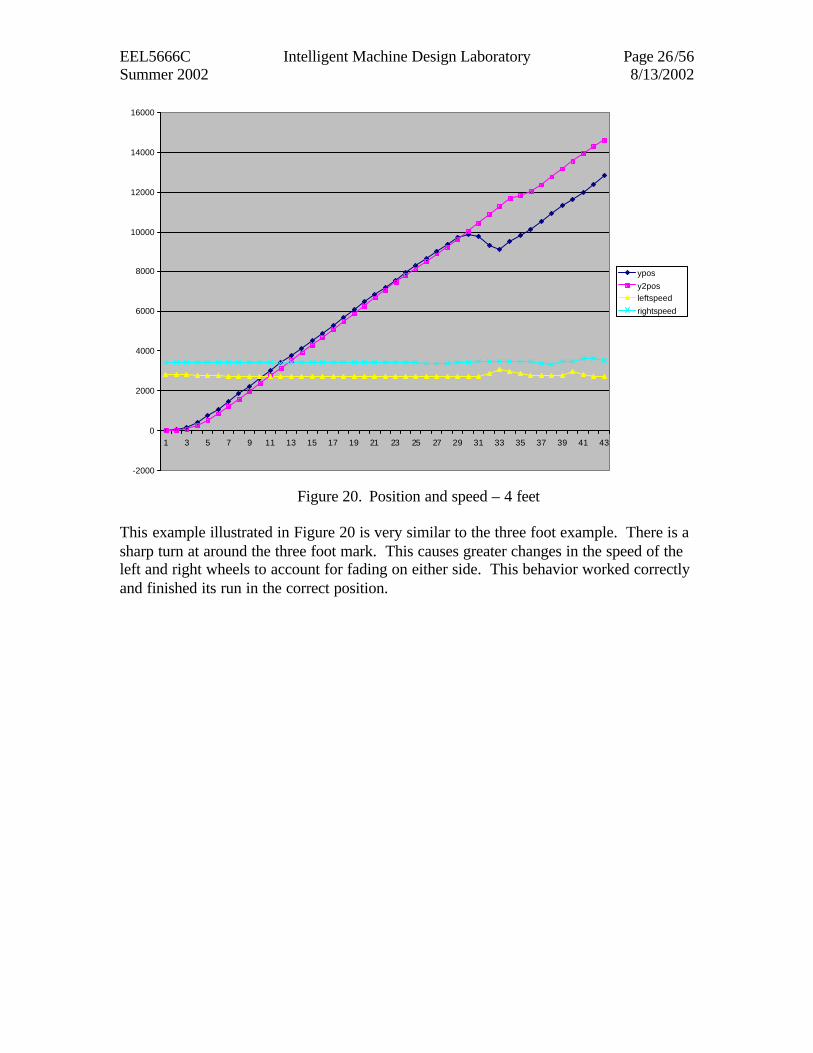
Figure 20. Position and speed – 4 feet
This example illustrated in Figure 20 is very similar to the three foot example. There is a sharp turn at around the three foot mark. This causes greater changes in the speed of the left and right wheels to account for fading on either side. This behavior worked correctly and finished its run in the correct position.
EEL5666C Intelligent Machine Design Laboratory Page 27/56 Summer 2002 8/13/2002
-2500
-2000
-1500
-1000
-500
0
500
1 3 5 7 9 11 13 15 17 19 21 23 25 27 29 31 33 35 37 39 41
ydif
change left speedchange right speed
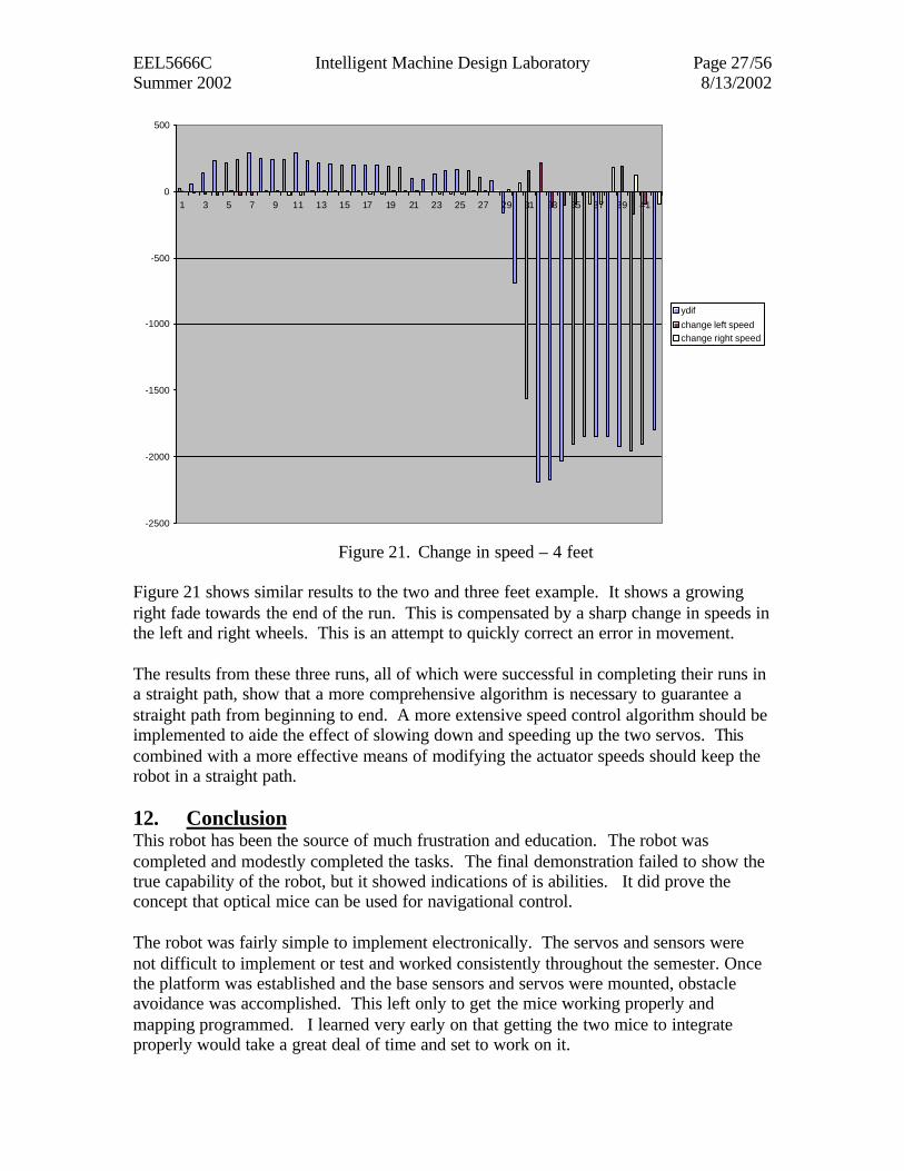
Figure 21. Change in speed – 4 feet
Figure 21 shows similar results to the two and three feet example. It shows a growing right fade towards the end of the run. This is compensated by a sharp change in speeds in the left and right wheels. This is an attempt to quickly correct an error in movement. The results from these three runs, all of which were successful in completing their runs in a straight path, show that a more comprehensive algorithm is necessary to guarantee a straight path from beginning to end. A more extensive speed control algorithm should be implemented to aide the effect of slowing down and speeding up the two servos. This combined with a more effective means of modifying the actuator speeds should keep the robot in a straight path. 12. Conclusion This robot has been the source of much frustration and education. The robot was completed and modestly completed the tasks. The final demonstration failed to show the true capability of the robot, but it showed indications of is abilities. It did prove the concept that optical mice can be used for navigational control. The robot was fairly simple to implement electronically. The servos and sensors were not difficult to implement or test and worked consistently throughout the semester. Once the platform was established and the base sensors and servos were mounted, obstacle avoidance was accomplished. This left only to get the mice working properly and mapping programmed. I learned very early on that getting the two mice to integrate properly would take a great deal of time and set to work on it.
EEL5666C Intelligent Machine Design Laboratory Page 28/56 Summer 2002 8/13/2002
The first attempt to integrate the mice was an idea to implement it with the serial port of the 68hc11. This was an attempt to get one mouse working quickly to learn about its possibilities as a sensor. This proved extremely difficult and complicated because the method for communicating with the programmer used the serial port. This idea was abandoned after a few weeks of work. The second attempt to integrate the mice was to use a CPLD I currently owned. This was a fine solution, but the CPLD was unable to hold the physical size of the programmable logic needed to interface the mice. This forced the purchase of the UP1 board which contained the Flex chip used in Ty Black’s successful implementation of the mice. After waiting a week for the board to arrive and another learning to program it, the mice worked. By this time several weeks had been wasted working on the mice and there was little time to program it. Once the mice were integrated together, it became clear that they did not give as accurate data as was advertised. However, the mice seemed to be very consistently giving data at about 1/285th of an inch. It required a great deal of time to realize this. The mice are also very susceptible to movement of the mice. If they are disturbed from resting on the ground, errors can be introduced. It is this problem that caused the most time loss. It took many weeks to determine that one of the problems was the platform, which as a two wheeled design, will rotate, causing the mice to lift slightly from the ground. This introduced error as well. It is clear from this project that there is potential for two or more mice to be used as a navigation tool. Further research could be done with the two mice design on a four wheel platform, thus eliminating the problem of mice lifting. Also, the mice should be mounted in such a way as they are independent from the actual robot. This may be accomplished by creating a guide in which the mice can be placed, as indicated in the platform portion of the paper. These corrections should eliminate many of the problems that plagued this design. If given the opportunity to redesign this robot, a more appropriate platform with a very detailed design for mounting the mice would be the first objective. With the mice now working, a more appropriate controller should also be chosen. A controller with an integrated FPGA would be most helpful. A small board with programmable logic and a microcontroller would greatly reduce the weight problems associated with the two evaluation boards. If such a board is not available, a smaller evaluation module for an FPGA should be utilized. Finally the mice should not be directly attached to the agent. This should reduce the errors causing such inconsistency in this design. The new robot should also be enhanced to utilize a network of infrared sensors. Many sensors would allow navigation in a room and make wall following very simple. Also, the robot should be shown to move straight and make accurate turns as a bare minimum. The straight line path should be accomplished with minute corrections and never deviate far from the center line.
EEL5666C Intelligent Machine Design Laboratory Page 29/56 Summer 2002 8/13/2002
Overall, the project was successful in proving that navigation can be accomplished in a two mouse design. The mapping functionality was not accomplished, but is not unattainable in the future. The robot was able to navigate in a straight line and turn accurately, thus providing the foundation for future work in this area. 13. Documentation [1] http://www.altera.com/ [2] http://www.howstuffworks.com/mouse3.htm [3] Ty Black, Sensor Report, IMDL [4] Ty Black, Final Report, IMDL [5] http://www.motorolla.com [6] http://www.mekatronics.com [7] http://mil.ufl.edu [8] http://www.acroname.com 14. Appendices 14.1. Avoid.c /************************************************************************ * MEKATRONIX Copyright 1998 * * Title avoid.c * * ProgrammerMichael Pusatera * * Date June 30, 2002 * * Version 1 * * * * Description * * Avoid obstacles. * ************************************************************************/ /**************************** Includes **********************************/ #include <tjpbase.h> /************************ End of includes *******************************/ #define Left_servo 2 #define Right_servo 1 #define left 2 #define right 1 #define random 0 #define Forward 3500 #define Backward 2500 #define Stop 0 #define FRONT_IR analog(1); void turn(int);
EEL5666C Intelligent Machine Design Laboratory Page 30/56 Summer 2002 8/13/2002
void main(void) /****************************** Main ***********************************/ { int i, irdr, irdl, irdf, bump; init_servome(); init_clocktjp(); init_analog(); while(BUMPER < 20); servo(Left_servo, Backward); servo(Right_servo, Forward); while(1) { irdr = RIGHT_IR; irdl = LEFT_IR; irdf = FRONT_IR; bump = BUMPER; servo(Left_servo, Backward); servo(Right_servo, Forward); if(irdf > 125) turn(random); if(irdr > 125) turn(left); if(irdl > 125) turn(right); if(bump > 60) { //back up servo(Left_servo, Forward); servo(Right_servo, Backward); turn(random); } } } /**************************** End of Main ******************************/ void turn(int dir) { int i; unsigned rand; rand = TCNT;
EEL5666C Intelligent Machine Design Laboratory Page 31/56 Summer 2002 8/13/2002
if(dir == 0) //front_ir turn random { if(rand & 0x0001) dir = left; //randomly turn right or left else dir = right; } if(dir == 1) //turn left servo(Left_servo, Forward); else servo(Right_servo, Backward); i=(rand % 1024); if(i>250) wait(i); else wait(250); return; } 14.2. GoReturn.c /************************************************************************ * Title goreturn.c * * ProgrammerMichael Pusatera * * Date July 31, 2002 * * Version 1 * * * * Description * * robot will go straight turn around and return* ************************************************************************/ /**************************** Includes **********************************/ #include <tjpbase.h> /************************ End of includes *******************************/ #define Left_servo 1 #define Right_servo 2 #define left 2 #define right 1 #define random 0 #define Forward 3700 #define Backward 2200 #define ForMin 3200 #define BackMin 2900

EEL5666C Intelligent Machine Design Laboratory Page 32/56 Summer 2002 8/13/2002
#define MaxSpeed 4500 #define MinSpeed 1000 #define Stop 0 #define FRONT_IR analog(1); #define d 2.62 //distance in inches #define inch 285 //factor for inches #define rad 3.75 #define pi 3.14 void getpos(void); void turn(float); void getmice(void); void straight(int); int ypos[1000], y2pos[1000], ydif[100], y2dif[1000]; int yinch[1000], y2inch[1000], anglea[100], dif[1000]; int lefta[1000], righta[1000], yturn[100], y2turn[100]; int i, yold, y2old; int xold, x2old; int xpos[100], x2pos[100]; int xinch[100], x2inch[100]; int xdif[100], x2dif[100]; int xa[100], x2a[100]; int irdr, irdl, irdf, bump; int mccr, mccr2, xh, xl, xh2, xl2, yh, yl, yh2, yl2; int diff, diff2, done; int x, y, x2, y2, oldy, oldy2; int leftspeed, rightspeed, marker; float thetay, thetax; void main(void) /****************************** Main ***********************************/ { marker = 0; init_servome(); init_clocktjp(); init_analog(); leftspeed=Backward; rightspeed=Forward; getmice(); wait(1000); servo(Left_servo, leftspeed); servo(Right_servo, rightspeed); i=0; yold = 0; y2old = 0;
EEL5666C Intelligent Machine Design Laboratory Page 33/56 Summer 2002 8/13/2002
oldy = 0; oldy2 = 0; straight(36); printf("out of 1st while\n"); servo(Left_servo, Stop); servo(Right_servo, Stop); leftspeed = Forward; //robot will turn in place rightspeed = Forward; wait(100); xold = xpos[i-1]; x2old = x2pos[i-1]; turn(pi); servo(Left_servo, Stop); servo(Right_servo, Stop); wait(100); leftspeed=Backward; rightspeed=Forward; oldy = ypos[i-1]; oldy2 = y2pos[i-1]; servo(Left_servo, leftspeed); servo(Right_servo, rightspeed); straight(36); //stop robot servo(Left_servo, Stop); servo(Right_servo, Stop); //wait for hook up to computer while(BUMPER < 20); while(BUMPER < 20); printf("ypos\t y2pos\t leftspeed \t rightspeed \t angle\t xpos\t x2pos\t dif\n"); for(i = 0; i<100; i++) printf("%d\t %d\t %d\t %d\t %d\t %d\t %d\t %d\n", ypos[i], y2pos[i], lefta[i], righta[i], anglea[i], xpos[i], x2pos[i], dif[i]); printf("oldy = %d oldy2 = %d\n", oldy, oldy2); return ; } /**************************** End of Main ******************************/ void turn(float angle) { marker = 0; while(marker != 1) {
EEL5666C Intelligent Machine Design Laboratory Page 34/56 Summer 2002 8/13/2002
if(i >=1000) i = 0; getmice(); getpos(); servo(Left_servo, leftspeed); servo(Right_servo, rightspeed); //printf("%d\t %d\t %d\t %d\t %d\t %d\t %d\t %d\n", ypos[i-1], y2pos[i-1], xpos[i-1], x2pos[i-1], anglea[i-1], ydif[i-1], y2dif[i-1], dif[i-1]); if((thetax >= (angle)) || (thetax <= (0 - (angle)))) marker = 1; //read data in wait(10); } return; } void getpos() { ypos[i] = y; y2pos[i] = y2; xpos[i] = x; x2pos[i] = x2; xinch[i] = x / inch; x2inch[i] = x2 / inch; yinch[i] = y / inch; y2inch[i] = y2 / inch; thetay = (y2 - y)/(inch*d); thetax = ((x2 - x2old)+ (x-xold))/ (2*rad*inch); anglea[i] = thetax; ydif[i] = y - yold; y2dif[i] = y2 - y2old; dif[i] = ypos[i] - y2pos[i]; yold = y; y2old = y2; i++; return ; } void getmice() { xh = *(unsigned char *) 0x7000; xl = *(unsigned char *) 0x7000; xh2 = *(unsigned char *) 0x7000; xl2 = *(unsigned char *) 0x7000; yh = *(unsigned char *) 0x7000;
EEL5666C Intelligent Machine Design Laboratory Page 35/56 Summer 2002 8/13/2002
yl = *(unsigned char *) 0x7000; yh2 = *(unsigned char *) 0x7000; yl2 = *(unsigned char *) 0x7000; mccr = *(unsigned char *) 0x7000; mccr2 = *(unsigned char *) 0x7000; //shift data in x and y x = xh; x2 = xh2; x = x << 8; x2 = x2 << 8; x = x + xl; x2 = x2 + xl2; y = yh; y2 = yh2; y = y << 8; y2 = y2 << 8; y = y + yl; y2 = y2 + yl2; return ; } void straight(int distance) { marker = 0; while(marker != 1) { if(i >=1000) i = 0; printf("in while\n"); //read data in getmice(); getpos(); printf("%d\t %d\t %d\t %d\t %d\t %d\t %d\t %d\n", ypos[i-1], y2pos[i-1], xpos[i-1], x2pos[i-1], anglea[i-1], ydif[i-1], y2dif[i-1], dif[i-1]); diff = (ypos[i-1] - oldy) - (y2pos[i-1] - oldy2); diff2 = ydif[i-1] - y2dif[i-1]; // if(diff > 0) {//on left if(diff2 > 0) { //veering left more if((leftspeed - (diff/4)) > MinSpeed) leftspeed = leftspeed - (diff/4); //speed up left else { if((rightspeed - (diff/4)) > ForMin) rightspeed = rightspeed - (diff/4); //slow down right else { leftspeed=Backward - (diff/4); rightspeed=Forward; }
EEL5666C Intelligent Machine Design Laboratory Page 36/56 Summer 2002 8/13/2002
} } else { //veering right--correcting if((rightspeed + (diff/8)) < MaxSpeed) rightspeed = rightspeed + (diff/8); //speed up right else { if((leftspeed + (diff/8)) < BackMin) leftspeed = leftspeed + (diff/8); //slow down left else { leftspeed=Backward; rightspeed=Forward + (diff/8); } } } } else { //on right diff = - diff; if(diff2 < 0) { //veering right more if((rightspeed + (diff/4)) < MaxSpeed) rightspeed = rightspeed + (diff/4); //speed up right else { if((leftspeed + (diff/4)) < BackMin) leftspeed = leftspeed + (diff/4); //slow down left else { leftspeed=Backward; rightspeed=Forward + (diff/4); } } } else { //veering left--correcting if((leftspeed - (diff/8)) > MinSpeed) leftspeed = leftspeed - (diff/8); //speed up left else { if((rightspeed - (diff/8)) > ForMin) rightspeed = rightspeed - (diff/8); //slow down right else { leftspeed=Backward - (diff/8); rightspeed=Forward; } } } } servo(Left_servo, leftspeed); servo(Right_servo, rightspeed); righta[i-1] = rightspeed; lefta[i-1] = leftspeed;
EEL5666C Intelligent Machine Design Laboratory Page 37/56 Summer 2002 8/13/2002
wait(70); done =((y2pos[i-1]-oldy2)+(ypos[i-1]-oldy))/2; if((done) >= (inch * distance)) marker = 1; } return ; } 14.3. Square.c /************************************************************************ * Title square.c * * ProgrammerMichael Pusatera * * Date July 31, 2002 * * Version 1 * * * * Description * * robot will map out a square* ***********************************************************************/ /**************************** Includes **********************************/ #include <tjpbase.h> /************************ End of includes *******************************/ #define Left_servo 1 #define Right_servo 2 #define left 2 #define right 1 #define random 0 #define Forward 3700 #define Backward 2200 #define ForMin 3200 #define BackMin 2900 #define MaxSpeed 4500 #define MinSpeed 1000 #define Stop 0 #define FRONT_IR analog(1); #define d 2.62 //distance in inches #define inch 285 //factor for inches #define rad 3.0 #define pi 3.14 void getpos(void); void turn(float); void getmice(void); void straight(int);
EEL5666C Intelligent Machine Design Laboratory Page 38/56 Summer 2002 8/13/2002
int ypos[1000], y2pos[1000], ydif[100], y2dif[1000]; int yinch[1000], y2inch[1000], anglea[100], dif[1000]; int lefta[1000], righta[1000], yturn[100], y2turn[100]; int i, yold, y2old; int xold, x2old; int xpos[100], x2pos[100]; int xinch[100], x2inch[100]; int xdif[100], x2dif[100]; int xa[100], x2a[100]; int irdr, irdl, irdf, bump; int mccr, mccr2, xh, xl, xh2, xl2, yh, yl, yh2, yl2; int diff, diff2, done; int x, y, x2, y2, oldy, oldy2; int leftspeed, rightspeed, marker; float thetay, thetax; void main(void) /****************************** Main ***********************************/ { marker = 0; init_servome(); init_clocktjp(); init_analog(); leftspeed=Backward; rightspeed=Forward; wait(1000); servo(Left_servo, leftspeed); servo(Right_servo, rightspeed); i=0; yold = 0; y2old = 0; oldy = 0; oldy2 = 0; straight(24); printf("out of 1st while\n"); servo(Left_servo, Stop); servo(Right_servo, Stop); leftspeed = Forward; //robot will turn in place rightspeed = Forward; wait(100); turn(pi/2); servo(Left_servo, Stop); servo(Right_servo, Stop);
EEL5666C Intelligent Machine Design Laboratory Page 39/56 Summer 2002 8/13/2002
oldy = ypos[i-1]; oldy2 = y2pos[i-1]; straight(24); printf("out of 1st while\n"); servo(Left_servo, Stop); servo(Right_servo, Stop); leftspeed = Forward; //robot will turn in place rightspeed = Forward; wait(100); turn(pi/2); servo(Left_servo, Stop); servo(Right_servo, Stop); oldy = ypos[i-1]; oldy2 = y2pos[i-1]; straight(24); printf("out of 1st while\n"); servo(Left_servo, Stop); servo(Right_servo, Stop); leftspeed = Forward; //robot will turn in place rightspeed = Forward; wait(100); turn(pi/2); servo(Left_servo, Stop); servo(Right_servo, Stop); oldy = ypos[i-1]; oldy2 = y2pos[i-1]; straight(24); servo(Left_servo, Stop); servo(Right_servo, Stop); //wait for hook up to computer while(BUMPER < 20); while(BUMPER < 20); printf("ypos\t y2pos\t leftspeed \t rightspeed \t angle\t xpos\t x2pos\t dif\n"); for(i = 0; i<100; i++) printf("%d\t %d\t %d\t %d\t %d\t %d\t %d\t %d\n", ypos[i], y2pos[i], lefta[i], righta[i], anglea[i], xpos[i], x2pos[i], dif[i]); printf("oldy = %d oldy2 = %d\n", oldy, oldy2); return ; }
EEL5666C Intelligent Machine Design Laboratory Page 40/56 Summer 2002 8/13/2002
/**************************** End of Main ******************************/ void turn(float angle) { marker = 0; while(marker != 1) { if(i >=1000) i = 0; getmice(); getpos(); servo(Left_servo, leftspeed); servo(Right_servo, rightspeed); //printf("%d\t %d\t %d\t %d\t %d\t %d\t %d\t %d\n", ypos[i-1], y2pos[i-1], xpos[i-1], x2pos[i-1], anglea[i-1], ydif[i-1], y2dif[i-1], dif[i-1]); if((thetax >= (angle)) || (thetax <= (0 - (angle)))) marker = 1; //read data in wait(30); } return; } void getpos() { ypos[i] = y; y2pos[i] = y2; xpos[i] = x; x2pos[i] = x2; xinch[i] = x / inch; x2inch[i] = x2 / inch; yinch[i] = y / inch; y2inch[i] = y2 / inch; thetay = (y2 - y)/(inch*d); thetax = (x2 + x)/ (2*rad*inch); anglea[i] = thetax; ydif[i] = y - yold; y2dif[i] = y2 - y2old; dif[i] = ypos[i] - y2pos[i]; yold = y; y2old = y2; i++; return ; } void getmice()
EEL5666C Intelligent Machine Design Laboratory Page 41/56 Summer 2002 8/13/2002
{ xh = *(unsigned char *) 0x7000; xl = *(unsigned char *) 0x7000; xh2 = *(unsigned char *) 0x7000; xl2 = *(unsigned char *) 0x7000; yh = *(unsigned char *) 0x7000; yl = *(unsigned char *) 0x7000; yh2 = *(unsigned char *) 0x7000; yl2 = *(unsigned char *) 0x7000; mccr = *(unsigned char *) 0x7000; mccr2 = *(unsigned char *) 0x7000; //shift data in x and y x = xh; x2 = xh2; x = x << 8; x2 = x2 << 8; x = x + xl; x2 = x2 + xl2; y = yh; y2 = yh2; y = y << 8; y2 = y2 << 8; y = y + yl; y2 = y2 + yl2; return ; } void straight(int distance) { marker = 0; while(marker != 1) { if(i >=1000) i = 0; printf("in while\n"); //read data in getmice(); getpos(); printf("%d\t %d\t %d\t %d\t %d\t %d\t %d\t %d\n", ypos[i-1], y2pos[i-1], xpos[i-1], x2pos[i-1], anglea[i-1], ydif[i-1], y2dif[i-1], dif[i-1]); diff = ypos[i-1] - y2pos[i-1]; diff2 = ydif[i-1] - y2dif[i-1]; // if(diff > 0) {//on left if(diff2 > 0) { //veering left more if((leftspeed - (diff/4)) > MinSpeed) leftspeed = leftspeed - (diff/4); //speed up left else {
EEL5666C Intelligent Machine Design Laboratory Page 42/56 Summer 2002 8/13/2002
if((rightspeed - (diff/4)) > ForMin) rightspeed = rightspeed - (diff/4); //slow down right else { leftspeed=Backward - (diff/4); rightspeed=Forward; } } } else { //veering right--correcting if((rightspeed + (diff/8)) < MaxSpeed) rightspeed = rightspeed + (diff/8); //speed up right else { if((leftspeed + (diff/8)) < BackMin) leftspeed = leftspeed + (diff/8); //slow down left else { leftspeed=Backward; rightspeed=Forward + (diff/8); } } } } else { //on right diff = - diff; if(diff2 < 0) { //veering right more if((rightspeed + (diff/4)) < MaxSpeed) rightspeed = rightspeed + (diff/4); //speed up right else { if((leftspeed + (diff/4)) < BackMin) leftspeed = leftspeed + (diff/4); //slow down left else { leftspeed=Backward; rightspeed=Forward + (diff/4); } } } else { //veering left--correcting if((leftspeed - (diff/8)) > MinSpeed) leftspeed = leftspeed - (diff/8); //speed up left else { if((rightspeed - (diff/8)) > ForMin) rightspeed = rightspeed - (diff/8); //slow down right else {
EEL5666C Intelligent Machine Design Laboratory Page 43/56 Summer 2002 8/13/2002
leftspeed=Backward - (diff/8); rightspeed=Forward; } } } } servo(Left_servo, leftspeed); servo(Right_servo, rightspeed); righta[i-1] = rightspeed; lefta[i-1] = leftspeed; wait(50); done =((y2pos[i-1]-oldy2)+(ypos[i-1]-oldy))/2; if((done) >= (inch * distance)) marker = 1; } return ; } 14.4. Straight.c /************************************************************************ * Title straight.c * * ProgrammerMichael Pusatera * * Date July 31, 2002 * * Version 1 * * * * Description * * robot will go straight for 4 feet* * * ************************************************************************/ /**************************** Includes **********************************/ #include <tjpbase.h> /************************ End of includes *******************************/ #define Left_servo 1 #define Right_servo 2 #define left 2 #define right 1 #define random 0 #define Forward 3400 #define Backward 2800 #define ForMin 3280
EEL5666C Intelligent Machine Design Laboratory Page 44/56 Summer 2002 8/13/2002
#define BackMin 3120 #define MaxSpeed 3500 #define MinSpeed 2700 #define Stop 0 #define FRONT_IR analog(1); #define d 2.62 //distance in inches #define inch 72 //factor for inches #define rad 3.75 #define pi 3.14 void getpos(void); void getmice(void); void straight(int); int ypos[100], y2pos[100], ydif[100], y2dif[100]; int yinch[100], y2inch[100], anglea[100], dif[100]; int lefta[100], righta[100], yturn[100], y2turn[100]; int i, yold, y2old; int xold, x2old; int xpos[100], x2pos[100]; int xinch[100], x2inch[100]; int xdif[100], x2dif[100]; int xa[100], x2a[100]; int irdr, irdl, irdf, bump; int mccr, mccr2, xh, xl, xh2, xl2, yh, yl, yh2, yl2; int diff, diff2, done; int x, y, x2, y2, oldy, oldy2; int leftspeed, rightspeed, marker; float thetay, thetax; void main(void) /****************************** Main ***********************************/ { marker = 0; init_servome(); init_clocktjp(); init_analog(); leftspeed=Backward; rightspeed=Forward; getmice(); wait(1000); servo(Left_servo, leftspeed); servo(Right_servo, rightspeed); i=0; yold = 0; y2old = 0;
EEL5666C Intelligent Machine Design Laboratory Page 45/56 Summer 2002 8/13/2002
oldy = 0; oldy2 = 0; straight(48); //stop robot servo(Left_servo, Stop); servo(Right_servo, Stop); //wait for hook up to computer while(BUMPER < 20); while(BUMPER < 20); printf("ypos\t y2pos\t leftspeed \t rightspeed \t angle\t xpos\t x2pos\t dif\n"); for(i = 0; i<100; i++) printf("%d\t %d\t %d\t %d\t %d\t %d\t %d\t %d\n", ypos[i], y2pos[i], lefta[i],
righta[i], anglea[i], xpos[i], x2pos[i], dif[i]); return ; } /**************************** End of Main ******************************/ void getpos() { ypos[i] = y; y2pos[i] = y2; xpos[i] = x; x2pos[i] = x2; xinch[i] = x / inch; x2inch[i] = x2 / inch; yinch[i] = y / inch; y2inch[i] = y2 / inch; thetay = (y2 - y)/(inch*d); thetax = ((x2 - x2old)+ (x-xold))/ (2*rad*inch); anglea[i] = thetax; ydif[i] = y - yold; y2dif[i] = y2 - y2old; dif[i] = ypos[i] - y2pos[i]; yold = y; y2old = y2; i++; return ; } void getmice() { xh = *(unsigned char *) 0x7000; xl = *(unsigned char *) 0x7000; xh2 = *(unsigned char *) 0x7000; xl2 = *(unsigned char *) 0x7000; yh = *(unsigned char *) 0x7000; yl = *(unsigned char *) 0x7000;
EEL5666C Intelligent Machine Design Laboratory Page 46/56 Summer 2002 8/13/2002
yh2 = *(unsigned char *) 0x7000; yl2 = *(unsigned char *) 0x7000; mccr = *(unsigned char *) 0x7000; mccr2 = *(unsigned char *) 0x7000; //shift data in x and y x = xh; x2 = xh2; x = x << 8; x2 = x2 << 8; x = x + xl; x2 = x2 + xl2; y = yh; y2 = yh2; y = y << 8; y2 = y2 << 8; y = y + yl; y2 = y2 + yl2; x = x/4; x2 = x2/4; y = y/4; y2 = y2/4; return ; } void straight(int distance) { marker = 0; while(marker != 1) { if(i >=1000) i = 0; printf("in while\n"); //read data in getmice(); getpos(); printf("%d\t %d\t %d\t %d\t %d\t %d\t %d\t %d\n", ypos[i-1], y2pos[i-1], xpos[i-1], x2pos[i-1], anglea[i-1], ydif[i-1], y2dif[i-1], dif[i-1]); diff = (ypos[i-1] - oldy) - (y2pos[i-1] - oldy2); diff2 = ydif[i-1] - y2dif[i-1]; // if(diff > 0) {//on left if(diff2 > 0) { //veering left more if((leftspeed - (diff/3)) > MinSpeed) leftspeed = leftspeed - (diff/3); //speed up left else { if((rightspeed - (diff/3)) > ForMin) rightspeed = rightspeed - (diff/3); //slow down right else {
EEL5666C Intelligent Machine Design Laboratory Page 47/56 Summer 2002 8/13/2002
leftspeed=Backward - (diff/3); rightspeed=Forward; } } } else { //veering right--correcting if((rightspeed + (diff/5)) < MaxSpeed) rightspeed = rightspeed + (diff/5); //speed up right else { if((leftspeed + (diff/5)) < BackMin) leftspeed = leftspeed + (diff/5); //slow down left else { leftspeed=Backward; rightspeed=Forward + (diff/5); } } } } else { //on right diff = - diff; if(diff2 < 0) { //veering right more if((rightspeed + (diff/3)) < MaxSpeed) rightspeed = rightspeed + (diff/3); //speed up right else { if((leftspeed + (diff/3)) < BackMin) leftspeed = leftspeed + (diff/3); //slow down left else { leftspeed=Backward; rightspeed=Forward + (diff/3); } } } else { //veering left--correcting if((leftspeed - (diff/5)) > MinSpeed) leftspeed = leftspeed - (diff/5); //speed up left else { if((rightspeed - (diff/5)) > ForMin) rightspeed = rightspeed - (diff/5); //slow down right else { leftspeed=Backward - (diff/5); rightspeed=Forward; } } } } servo(Left_servo, leftspeed);
EEL5666C Intelligent Machine Design Laboratory Page 48/56 Summer 2002 8/13/2002
servo(Right_servo, rightspeed); righta[i-1] = rightspeed; lefta[i-1] = leftspeed; wait(50); done =((y2pos[i-1]-oldy2)+(ypos[i-1]-oldy))/2; if((done) >= (inch * distance)) marker = 1; } return ; } 14.5. Mouse16.vhd[3] --mouse to talrik --column = x --row = y LIBRARY IEEE; USE IEEE.STD_LOGIC_1164.all; USE IEEE.STD_LOGIC_ARITH.all; USE IEEE.STD_LOGIC_UNSIGNED.all; ENTITY mouse16 IS PORT( clock_25Mhz, reset : IN std_logic; SIGNAL mouse_data : INOUT std_logic; SIGNAL mouse_clk : INOUT std_logic; SIGNAL left_button, right_button: OUT std_logic; SIGNAL mouse_y : OUT std_logic_vector(15 DOWNTO 0); SIGNAL mouse_x : OUT std_logic_vector(15 DOWNTO 0); signal mouse_condition_register : out std_logic_vector(7 downto 0)); END mouse16; ARCHITECTURE behavior OF mouse16 IS TYPE STATE_TYPE IS (INHIBIT_TRANS, LOAD_COMMAND,LOAD_COMMAND2, WAIT_OUTPUT_READY, WAIT_CMD_ACK, INPUT_PACKETS); -- Signals for Mouse SIGNAL mouse_state : state_type; SIGNAL inhibit_wait_count : std_logic_vector(10 DOWNTO 0); SIGNAL CHARIN, CHAROUT : std_logic_vector(7 DOWNTO 0); SIGNAL new_y, new_x : std_logic_vector(15 DOWNTO 0); SIGNAL y, x : std_logic_vector(15 DOWNTO 0);
EEL5666C Intelligent Machine Design Laboratory Page 49/56 Summer 2002 8/13/2002
SIGNAL INCNT, OUTCNT, mSB_OUT : std_logic_vector(3 DOWNTO 0); SIGNAL PACKET_COUNT : std_logic_vector(1 DOWNTO 0); SIGNAL SHIFTIN : std_logic_vector(8 DOWNTO 0); SIGNAL SHIFTOUT : std_logic_vector(10 DOWNTO 0); SIGNAL PACKET_CHAR1, PACKET_CHAR2, PACKET_CHAR3 : std_logic_vector(7 DOWNTO 0); SIGNAL MOUSE_CLK_BUF, DATA_READY, READ_CHAR : std_logic; SIGNAL i : integer; SIGNAL cursor, iready_set, break, toggle_next, output_ready, send_char, send_data : std_logic; SIGNAL MOUSE_DATA_DIR, MOUSE_DATA_OUT, MOUSE_DATA_BUF, MOUSE_CLK_DIR : std_logic; SIGNAL MOUSE_CLK_FILTER : std_logic; SIGNAL filter : std_logic_vector(7 DOWNTO 0); signal condition_register : std_logic_vector(7 DOWNTO 0); BEGIN mouse_y <= y; mouse_x <= x; mouse_condition_register <= condition_register; -- tri_state control logic for mouse data and clock lines MOUSE_DATA <= 'Z' WHEN MOUSE_DATA_DIR = '0' ELSE MOUSE_DATA_BUF; MOUSE_CLK <= 'Z' WHEN MOUSE_CLK_DIR = '0' ELSE MOUSE_CLK_BUF; -- state machine to send init command and start recv process. PROCESS (reset, clock_25Mhz) BEGIN IF reset = '1' THEN mouse_state <= INHIBIT_TRANS; inhibit_wait_count <= conv_std_logic_vector(0,11); SEND_DATA <= '0'; ELSIF clock_25Mhz'EVENT AND clock_25Mhz = '1' THEN CASE mouse_state IS -- Mouse powers up and sends self test codes, AA and 00 out -- before board is downloaded -- Pull clock line low to inhibit any transmissions from mouse -- Need at least 60usec to stop a transmission in progress -- Note: This is perhaps optional since mouse should not be tranmitting WHEN INHIBIT_TRANS => inhibit_wait_count <= inhibit_wait_count + 1; IF inhibit_wait_count(10 DOWNTO 9) = "11" THEN
EEL5666C Intelligent Machine Design Laboratory Page 50/56 Summer 2002 8/13/2002
mouse_state <= LOAD_COMMAND; END IF; -- Enable Streaming Mode Command, F4 charout <= "11110100"; -- Pull data low to signal data available to mouse WHEN LOAD_COMMAND => SEND_DATA <= '1'; mouse_state <= LOAD_COMMAND2; WHEN LOAD_COMMAND2 => SEND_DATA <= '1'; mouse_state <= WAIT_OUTPUT_READY; -- Wait for Mouse to Clock out all bits in command. -- Command sent is F4, Enable Streaming Mode -- This tells the mouse to start sending 3-byte packets with movement data WHEN WAIT_OUTPUT_READY => SEND_DATA <= '0'; -- Output Ready signals that all data is clocked out of shift register IF OUTPUT_READY='1' THEN mouse_state <= WAIT_CMD_ACK; ELSE mouse_state <= WAIT_OUTPUT_READY; END IF; -- Wait for Mouse to send back Command Acknowledge, FA WHEN WAIT_CMD_ACK => SEND_DATA <= '0'; IF IREADY_SET='1' THEN mouse_state <= INPUT_PACKETS; END IF; -- Release clock_25Mhz and data lines and go into mouse input mode -- Stay in this state and recieve 3-byte mouse data packets forever -- Default rate is 100 packets per second WHEN INPUT_PACKETS => mouse_state <= INPUT_PACKETS; END CASE; END IF; END PROCESS; WITH mouse_state SELECT -- Mouse Data Tri-state control line: '1' FLEX Chip drives, '0'=Mouse Drives MOUSE_DATA_DIR <= '0' WHEN INHIBIT_TRANS, '0' WHEN LOAD_COMMAND, '0' WHEN LOAD_COMMAND2, '1' WHEN WAIT_OUTPUT_READY, '0' WHEN WAIT_CMD_ACK, '0' WHEN INPUT_PACKETS; -- Mouse Clock Tri-state control line: '1' FLEX Chip drives, '0'=Mouse Drives WITH mouse_state SELECT MOUSE_CLK_DIR <= '1' WHEN INHIBIT_TRANS, '1' WHEN LOAD_COMMAND, '1' WHEN LOAD_COMMAND2, '0' WHEN WAIT_OUTPUT_READY,

EEL5666C Intelligent Machine Design Laboratory Page 51/56 Summer 2002 8/13/2002
'0' WHEN WAIT_CMD_ACK, '0' WHEN INPUT_PACKETS; WITH mouse_state SELECT -- Input to FLEX chip tri-state buffer mouse clock_25Mhz line MOUSE_CLK_BUF <= '0' WHEN INHIBIT_TRANS, '1' WHEN LOAD_COMMAND, '1' WHEN LOAD_COMMAND2, '1' WHEN WAIT_OUTPUT_READY, '1' WHEN WAIT_CMD_ACK, '1' WHEN INPUT_PACKETS; -- filter for mouse clock PROCESS BEGIN WAIT UNTIL clock_25Mhz'event and clock_25Mhz = '1'; filter(7 DOWNTO 1) <= filter(6 DOWNTO 0); filter(0) <= MOUSE_CLK; IF filter = "11111111" THEN MOUSE_CLK_FILTER <= '1'; ELSIF filter = "00000000" THEN MOUSE_CLK_FILTER <= '0'; END IF; END PROCESS; --This process sends serial data going to the mouse SEND_UART: PROCESS (send_data, Mouse_clK_filter) BEGIN IF SEND_DATA = '1' THEN OUTCNT <= "0000"; SEND_CHAR <= '1'; OUTPUT_READY <= '0'; -- Send out Start Bit(0) + Command(F4) + Parity Bit(0) + Stop Bit(1) SHIFTOUT(8 DOWNTO 1) <= CHAROUT ; -- START BIT SHIFTOUT(0) <= '0'; -- COMPUTE ODD PARITY BIT SHIFTOUT(9) <= not (charout(7) xor charout(6) xor charout(5) xor charout(4) xor Charout(3) xor charout(2) xor charout(1) xor charout(0)); -- STOP BIT SHIFTOUT(10) <= '1'; -- Data Available Flag to Mouse -- Tells mouse to clock out command data (is also start bit) MOUSE_DATA_BUF <= '0'; ELSIF(MOUSE_CLK_filter'event and MOUSE_CLK_filter='0') THEN IF MOUSE_DATA_DIR='1' THEN -- SHIFT OUT NEXT SERIAL BIT IF SEND_CHAR = '1' THEN -- Loop through all bits in shift register IF OUTCNT <= "1001" THEN OUTCNT <= OUTCNT + 1; -- Shift out next bit to mouse
EEL5666C Intelligent Machine Design Laboratory Page 52/56 Summer 2002 8/13/2002
SHIFTOUT(9 DOWNTO 0) <= SHIFTOUT(10 DOWNTO 1); SHIFTOUT(10) <= '1'; MOUSE_DATA_BUF <= SHIFTOUT(1); OUTPUT_READY <= '0'; -- END OF CHARACTER ELSE SEND_CHAR <= '0'; -- Signal the character has been output OUTPUT_READY <= '1'; OUTCNT <= "0000"; END IF; END IF; END IF; END IF; END PROCESS SEND_UART; RECV_UART: PROCESS(reset, mouse_clk_filter) BEGIN IF RESET='1' THEN INCNT <= "0000"; READ_CHAR <= '0'; PACKET_COUNT <= "00"; LEFT_BUTTON <= '0'; RIGHT_BUTTON <= '0'; CHARIN <= "00000000"; ELSIF MOUSE_CLK_FILTER'event and MOUSE_CLK_FILTER='1' THEN IF MOUSE_DATA_DIR='0' THEN IF MOUSE_DATA='0' AND READ_CHAR='0' THEN READ_CHAR<= '1'; IREADY_SET<= '0'; ELSE -- SHIFT IN NEXT SERIAL BIT IF READ_CHAR = '1' THEN IF INCNT < "1001" THEN INCNT <= INCNT + 1; SHIFTIN(7 DOWNTO 0) <= SHIFTIN(8 DOWNTO 1); SHIFTIN(8) <= MOUSE_DATA; IREADY_SET <= '0'; -- END OF CHARACTER ELSE CHARIN <= SHIFTIN(7 DOWNTO 0); READ_CHAR <= '0'; IREADY_SET <= '1'; PACKET_COUNT <= PACKET_COUNT + 1; -- PACKET_COUNT = "00" IS ACK COMMAND IF PACKET_COUNT = "00" THEN -- Set Cursor to middle of screen -- I CHANGED THIS x <= CONV_STD_LOGIC_VECTOR(0,16); y <= CONV_STD_LOGIC_VECTOR(0,16); new_x <= CONV_STD_LOGIC_VECTOR(0,16); new_y <= CONV_STD_LOGIC_VECTOR(0,16);
EEL5666C Intelligent Machine Design Laboratory Page 53/56 Summer 2002 8/13/2002
ELSIF PACKET_COUNT = "01" THEN PACKET_CHAR1 <= SHIFTIN(7 DOWNTO 0); y <= new_y; x <= new_x; --END IF; ELSIF PACKET_COUNT = "10" THEN PACKET_CHAR2 <= SHIFTIN(7 DOWNTO 0); ELSIF PACKET_COUNT = "11" THEN PACKET_CHAR3 <= SHIFTIN(7 DOWNTO 0); END IF; INCNT <= conv_std_logic_vector(0,4); IF PACKET_COUNT = "11" THEN PACKET_COUNT <= "01"; -- Packet Complete, so process data in packet -- Sign extend X AND Y two's complement motion values and -- add to Current Cursor Address -- -- Y Motion is Negative since up is a lower x address condition_register <= PACKET_CHAR1 ; new_y <= y + ( PACKET_CHAR3(7) & PACKET_CHAR3(7) & PACKET_CHAR3(7) & PACKET_CHAR3(7) & PACKET_CHAR3(7) & PACKET_CHAR3(7) & PACKET_CHAR3(7) & PACKET_CHAR3(7) & PACKET_CHAR3(7) & PACKET_CHAR3); new_x <= x + ( PACKET_CHAR2(7) & PACKET_CHAR2(7) & PACKET_CHAR2(7) & PACKET_CHAR2(7) & PACKET_CHAR2(7) & PACKET_CHAR2(7) & PACKET_CHAR2(7) & PACKET_CHAR2(7) & PACKET_CHAR2(7) & PACKET_CHAR2); LEFT_BUTTON <= PACKET_CHAR1(0); RIGHT_BUTTON <= PACKET_CHAR1(1); END IF; END IF; END IF; END IF; END IF; END IF; END PROCESS RECV_UART; END behavior; 14.6. Output Controller (memorymapwmice.vhd) library ieee; use ieee.std_logic_1164.all;
EEL5666C Intelligent Machine Design Laboratory Page 54/56 Summer 2002 8/13/2002
USE IEEE.STD_LOGIC_ARITH.all; entity memorymapwmice is port( cs :in std_logic; clk_25MHz :in std_logic; y, x, y_2, x_2 :IN std_logic_vector(15 DOWNTO 0); cond, cond_2 :IN std_logic_vector(7 DOWNTO 0); outbus :out std_logic_vector(7 downto 0) ); end memorymapwmice ; architecture structure of memorymapwmice is signal buf : std_logic_vector(7 downto 0); SIGNAL filter : std_LOGIC_vector(1 DOWNTO 0) ; signal cs_filter : std_logic ; TYPE ASMstateType IS (init, XL, XL2, XH, XH2, MCCR, MCCR2, YH, YL, YH2, YL2) ; SIGNAL state : ASMstateType ; begin process (clk_25MHz) begin if clk_25MHz'event and clk_25MHz= '1' then filter(0) <= cs ; filter(1) <= filter(0) ; end if ; end process ; WITH filter select cs_filter <= '0' WHEN "00" , '1' WHEN OTHERS ; PROCESS (cs_filter) begin if cs_filter'event AND cs_filter = '1' then case state is WHEN init => state <= XH; WHEN XH => state <= XL; WHEN XL => state <= XH2; WHEN XH2 => state <= XL2; When XL2 =>

EEL5666C Intelligent Machine Design Laboratory Page 55/56 Summer 2002 8/13/2002
state <= YH ; WHEN YH => state <= YL; WHEN YL => state <= YH2; WHEN YH2 => state <= YL2; WHEN YL2 => state <= MCCR; When MCCR=> state <= MCCR2 ; When MCCR2=> state <= XH ; END CASE ; end if ; end process ; WITH cs select outbus <= buf WHEN '0' , "ZZZZZZZZ" WHEN OTHERS ; WITH state select buf <= x(15 DOWNTO 8) WHEN XH , x( 7 DOWNTO 0) WHEN XL , x_2(15 DOWNTO 8) WHEN XH2 , x_2( 7 DOWNTO 0) WHEN XL2 , y(15 DOWNTO 8) WHEN YH , y( 7 DOWNTO 0) WHEN YL , y_2(15 DOWNTO 8) WHEN YH2 , y_2( 7 DOWNTO 0) WHEN YL2 , cond(7 DOWNTO 0) WHEN MCCR , cond_2( 7 DOWNTO 0) WHEN MCCR2 , "00000000" WHEN others ; end structure;
EEL5666C Intelligent Machine Design Laboratory Page 56/56 Summer 2002 8/13/2002
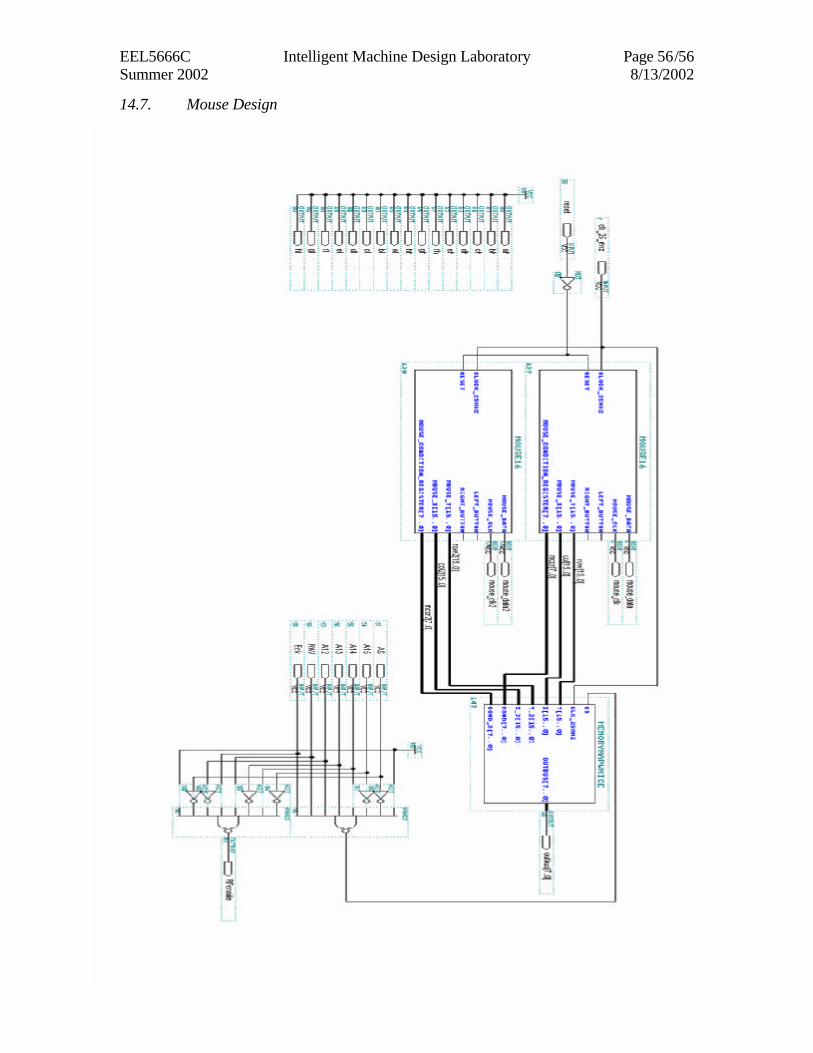
14.7. Mouse Design