Embed Size (px)
Citation preview
JOURNAL OF AIRCRAFT
Vol. 43, No. 1, January–February 2006
Effects of Winglet Dihedral on a Tip Vortex
P. Gerontakos∗ and T. Lee†
McGill University, Montreal, Quebec H3A 2K6, Canada
The effect of winglet dihedral (−−87.5 <– δ <– 87.5 deg) on the near-field tip vortex flow structure behind a sweptand tapered NACA 0015 wing was investigated at Re = 1.81 ×× 105. The winglet dihedral led to a significantlyreduced (increased) peak tangential velocity and vorticity (core radius) compared to a baseline wing. The valuesof core circulation (core axial velocity) could be below or above the baseline-wing value, depending on the wingletangle, and exhibited a local maximum (minimum) at δ = 0 deg. The inner region of the tip vortex flow exhibiteda self-similar behavior for a wing with and with no winglet. The lift-induced drag was always reduced by theaddition of a winglet. The negative dihedral was more effective in reducing the lift-induced drag compared to thecorresponding winglet of positive dihedral. A large discrepancy in the lift-induced drag was, however, observedbetween the wake integral method and the classical lifting-line theory.
NomenclatureAR = aspect ratio, b2/Sb = (semi-)wing spanCD = total drag coefficientCDi = lift-induced drag coefficient, Di/
12ρu∞2 S
CL = lift coefficientc = chordDi = lift-induced dragL = lift forceRe = Reynolds number, u∞cr/νr = radial positionrc = core radiusro = outer radiusS = wing areau = axial mean velocityuc = core axial velocityu∞ = freestream velocityv = transverse mean velocityvθ = tangential velocityw = spanwise mean velocityx = streamwise or axial directiony = transverse directionz = spanwise directionα = angle of attack� = circulation or vortex strength�b = bound circulation�c = core circulation�o = total circulationδ = winglet dihedralζ = streamwise vorticity = sweep angleλ = taper ratio, ct/crν = kinematic viscosityρ = fluid densityσ = source term in Eq. (3), ∂v/∂y + ∂w/∂zφ = velocity potentialψ = stream function
Received 19 October 2004; revision received 27 January 2005; acceptedfor publication 27 January 2005. Copyright c© 2005 by P. Gerontakos andT. Lee. Published by the American Institute of Aeronautics and Astronautics,Inc., with permission. Copies of this paper may be made for personal orinternal use, on condition that the copier pay the $10.00 per-copy fee tothe Copyright Clearance Center, Inc., 222 Rosewood Drive, Danvers, MA01923; include the code 0021-8669/06 $10.00 in correspondence with theCCC.
∗Graduate Research Assistant, Department of Mechanical Engineering,817 Sherbrooke Street West.
†Associate Professor, Department of Mechanical Engineering, 817 Sher-brooke Street West. Member AIAA.
Introduction
T HE counter-rotating longitudinal vortices generated by aircraftwing tips, because of their hazardous effects on flight safety,
continue to be of concern to the aviation industry and aircraft man-ufacturers alike. Moreover, tip vortices shed from helicopter rotorblades and propellers interact with following blades causing exces-sive rotor noise and vibration. Therefore, to reduce the flight timeand separation distance of aircraft during takeoff and landing, aswell as to reduce the tip vortex-induced drag and noise, the trailingvortex wake characteristics must be measured and predicted accu-rately and reduced or eliminated, if possible.
Various passive1−7 and active1,8,9 tip geometry modification de-vices, such as endplates, winglets and tip sails, tailored and rakedwingtips, and steady or pulsating blowing jets of air into the vortexregion, have been proposed to minimize the strength of the trailingvortex and to reduce the lift-induced drag. Among them, the winglethas been widely recognized as a more efficient means of improvingcruise drag performance than a simple spanwise tip extension withthe same structural weight penalty. The wing-tip-mounted, nearlyvertical winglet can also develop a normal force that alters the con-figuration span load to diffuse the total circulation in the rolled-upwing-tip vortex and reduce the total energy of the vortex. The basicphysical effect of the winglets,2 which leads to drag reduction, is avertical diffusion of the tip vortex flow, at least just downstream ofthe tip, which substantially reduces the magnitudes of the crossflowbehind the tip. Also, the presence of a lower winglet lessens theinduced velocities on the upper winglet and results in a decreasedboundary-layer separation on the winglet inner surface.
Recently, Eppler6 suggested that a spanwise tip extension witha dihedral of about 10 deg rendered a lower induced drag than aplanar wing with the same length through the nonlinear effect ofinduced lift, which had the effect of decreasing the induced drag fora given lift. The induced lift was caused by the velocity that liftingvortices induced on themselves and did not develop on a planar wing.Furthermore, although the span was reduced by deflecting the tip,the wing performed better than a planar wing with the same length,or wetted area. Gold and Visser7 later examined the impact of thedihedral on the performance of a swept and tapered NACA 0012wing fitted with a winglet and reported that the negative dihedralyielded a lower lift-induced drag than the zero and positive dihedralconfigurations.
In summary, despite much work, the bulk of the experimental in-vestigations were mainly concentrated on direct wind-tunnel forcebalance and surface pressure measurements. Detailed surveys ofthe tip-vortex flow structure behind a winglet, especially in the nearwake of the generating wing, are still needed. The objective of thepresent study was to investigate the three-dimensional flow struc-ture of the tip vortex in the near field behind a sweptback and ta-pered NACA 0015 wing with and without a winglet of different
117
Dow
nloa
ded
by U
NIV
ER
SIT
Y O
F W
ISC
ON
SIN
MA
DIS
ON
on
Sept
embe
r 26
, 201
4 | h
ttp://
arc.
aiaa
.org
| D
OI:
10.
2514
/1.1
4052
118 GERONTAKOS AND LEE
dihedrals by using a miniature seven-hole pressure probe at a root-chord Reynolds number Re = 1.81 × 10⁵. Particular attention wasfocused on the effects of the winglet dihedral on the variation ofthe crossflow and axial velocity and vorticity distributions and thestrength, size, and trajectory of the vortex, as well as the estima-tion of the bound and spanwise circulation. Lift-induced drag wascomputed using a wake integral method and was compared with thewind-tunnel force balance data.
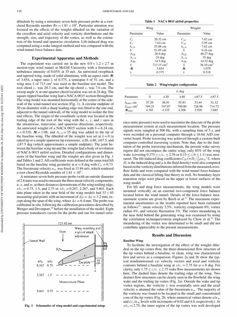
Experimental Apparatus and MethodsThe experiment was carried out in the new 0.9 × 1.2 × 2.7 m
suction-type wind tunnel at McGill University with a freestreamturbulence intensity of 0.03% at 35 m/s. An untwisted sweptbackand tapered wing, made of solid aluminum, with an aspect ratio ARof 3.654, a taper ratio λ of 0.375, a semispan b of 51 cm, and awing area S of 713 cm2 was used as the baseline test model. Theroot chord cr was 20.3 cm, and the tip chord ct was 7.6 cm. Thesweep angle at one-quarter-chord location was set at 24 deg. Thesquare-tipped baseline wing had a NACA 0015 section throughout.The wing model was mounted horizontally at the center of the side-wall of the wind-tunnel test section (Fig. 1). A circular endplate of50 cm diameter with a sharp leading edge was fitted to the one end,adjacent to the tunnel sidewall, of the wing model to isolate the freeend effects. The origin of the coordinate system was located at thetrailing edge of the root of the wing with the x , y, and z axes inthe streamwise, transverse, and spanwise directions, respectively.An untwisted winglet of a NACA 0015 section with b = 6.24 cm,λ = 0.518, AR = 1.08, and c/4 = 35 deg was added to the tip ofthe baseline wing. The dihedral of the winglet was set at δ = 0 (araked tip or a simple spanwise tip extension), ±20, ±40, ±67.5, and±87.5 deg (which approximates a simple endplate). The joint be-tween the baseline wing tip and the winglet had a body of revolutionof NACA 0015 airfoil section. Detailed configurations and dimen-sions of the baseline wing and the winglet are also given in Fig. 1and Tables 1 and 2. All coefficients were defined at the same total liftbased on the baseline wing geometry at α = 8 deg with CL = 0.73.The freestream velocity u∞ was fixed at 13.84 m/s, which rendereda root-chord Reynolds number of 1.81 × 10⁵.
A miniature seven-hole pressure probe (with an outside diameterof 2.6 mm) was used to measure the three mean velocity components,u, v, and w, at three distances downstream of the wing trailing edge,x /cr = 0.75, 1.5, and 2.75 or x /ct = 0.267, 2.267, and 5.601. Eachdata plane taken in the near field of the wing models had 33 × 85measuring grid points with an increment of �y = �z = 3.2 mm, ex-cept along the span of the wing, where �z = 6.4 mm. The probe wascalibrated in situ, following the calibration procedures described byWenger and Devenport,10 before the installation of the model. Eightpressure transducers (seven for the probe and one for tunnel refer-
Fig. 1 Schematics of wing model and experimental setup.
Table 1 NACA 0015 airfoil properties
Wing Winglet
Parameter Value Parameter Value
Cr 20.32 cm Cwr 7.62 cmCt 7.62 cm Cwt 3.95 cmbc/4 55.88 cm bc/4 7.62 cmb 51.05 cm b 6.24 cmLE 26.9 deg LE 40.27 degc/4 24 deg c/4 35 degTE 14.5 deg TE 14.52 deg
S 713.15 cm2 S 36.10 cm2
AR 3.654 AR 1.079λ 0.375 λ 0.518
Table 2 Wing/winglet configuration
δ, deg
Parameter 0 ±20 ±40 ±67.5 ±87.5
btotal, cm 57.29 56.91 55.83 53.44 51.32
Stotal, cm2 749.25 747.07 740.80 726.96 714.72ARtotal 4.381 4.335 4.208 3.928 3.685
ence static pressure) were used to maximize the data rate of the probemeasurement system at each measurement location. The pressuresignals were sampled at 500 Hz, with a sampling time of 5 s, andwere recorded on a personal computer through a 16-bit A/D con-verter board. Probe traversing was achieved through a custom-builtcomputer-controlled traversing system. Note that, due to the limi-tation of the probe traversing mechanism, the present wake surveyregion did not encompass the entire wing; only 85% of the wingwake (covering 0.375 ≤ z/cr ≤ 2.76 or 0.15 ≤ z/b ≤ 1.1) was mea-sured. The lift-induced drag coefficients CDi (=Di/
12ρu∞2 S, where
Di is the induced drag and ρ is the fluid density) were also computedbased on the vorticity distributions inferred from the measured cross-flow fields and were compared with the wind-tunnel force-balancedata and the classical lifting-line theory as well. No boundary-layertransition strips were placed on the upper or lower surfaces of thewing model.
For lift and drag force measurements, the wing models weremounted vertically on an external two-component force balancelocated below the wind tunnel. Details of the force-balance mea-surement system are given by Birch et al.11 The maximum exper-imental uncertainties in the results reported have been estimatedas follows11: mean velocity 3.5%, vorticity component 8%, vortexradius 4%, and velocity fluctuation 3%. The vortex meandering inthe near field behind the generating wing was examined by usingthe correlation technique/criteria employed by Chow et al.12 Themeandering of the vortex was determined to be small and did notcontribute appreciably to the present measurements.
Results and DiscussionBaseline Wing
To facilitate the investigation of the effect of the winglet dihe-dral on the tip-vortex flow, the three-dimensional flow structure ofthe tip vortex behind a baseline, or clean, wing was characterizedfirst and serves as a comparison. Figures 2a and 2b show the typ-ical nondimensional vw velocity vectors and axial and vorticitycontours behind a baseline wing at x /cr = 2.75 for α = 8 deg. Forclarity, only 1.75 ≤ z/cr ≤ 2.75 wake flow measurements are shownhere. The dashed lines denote the trailing edge of the wing. Twodistinct flow structures can be clearly seen in the flowfield: the wingwake and the trailing tip vortex (Fig. 2a). Outside the wake and tipvortex regions, the vorticity ζ was essentially zero and the axialvelocity u attained the value of the freestream u∞. The majority ofthe vorticity was found to be located in the small and concentratedcore of the tip vortex (Fig. 2b, where numerical values denote u/u∞and ζcr /u∞ levels with increments of 0.02 and 4.0, respectively). Atx /cr = 2.75, the inner region of the tip vortex was well developed
Dow
nloa
ded
by U
NIV
ER
SIT
Y O
F W
ISC
ON
SIN
MA
DIS
ON
on
Sept
embe
r 26
, 201
4 | h
ttp://
arc.
aiaa
.org
| D
OI:
10.
2514
/1.1
4052
GERONTAKOS AND LEE 119
a)
b)
c)
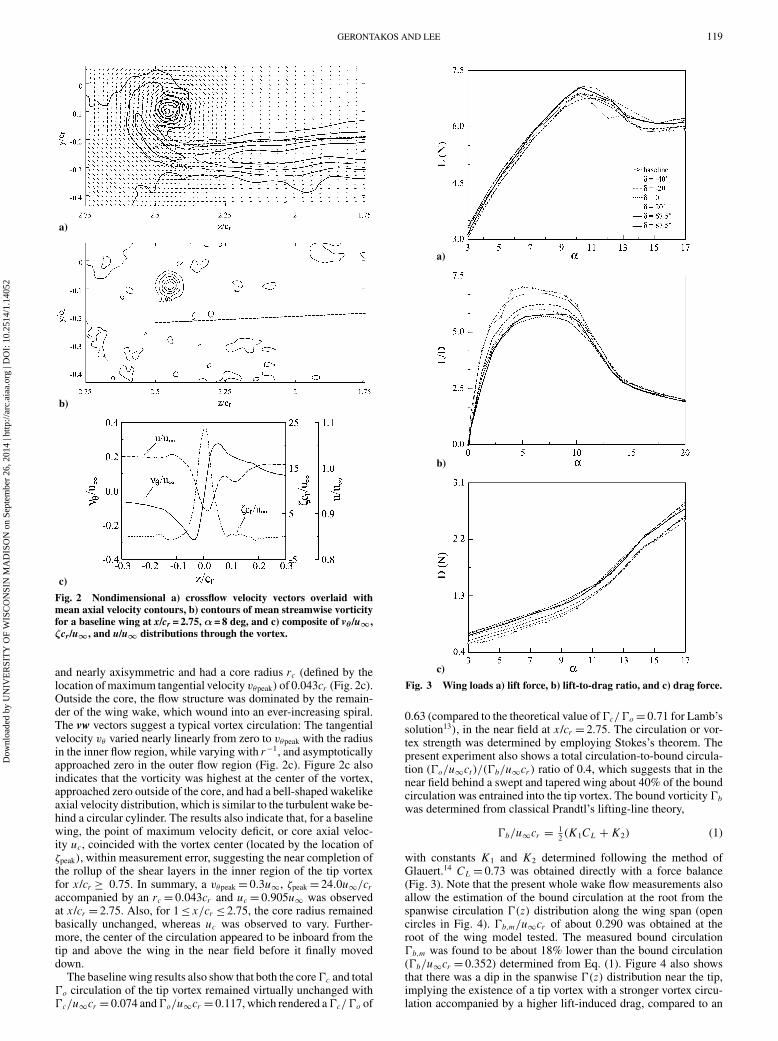
Fig. 2 Nondimensional a) crossflow velocity vectors overlaid withmean axial velocity contours, b) contours of mean streamwise vorticityfor a baseline wing at x/cr = 2.75, α= 8 deg, and c) composite of vθ /u∞,ζcr/u∞, and u/u∞ distributions through the vortex.
and nearly axisymmetric and had a core radius rc (defined by thelocation of maximum tangential velocity vθpeak) of 0.043cr (Fig. 2c).Outside the core, the flow structure was dominated by the remain-der of the wing wake, which wound into an ever-increasing spiral.The vw vectors suggest a typical vortex circulation: The tangentialvelocity vθ varied nearly linearly from zero to vθpeak with the radiusin the inner flow region, while varying with r−1, and asymptoticallyapproached zero in the outer flow region (Fig. 2c). Figure 2c alsoindicates that the vorticity was highest at the center of the vortex,approached zero outside of the core, and had a bell-shaped wakelikeaxial velocity distribution, which is similar to the turbulent wake be-hind a circular cylinder. The results also indicate that, for a baselinewing, the point of maximum velocity deficit, or core axial veloc-ity uc, coincided with the vortex center (located by the location ofζpeak), within measurement error, suggesting the near completion ofthe rollup of the shear layers in the inner region of the tip vortexfor x /cr ≥ 0.75. In summary, a vθpeak = 0.3u∞, ζpeak = 24.0u∞/craccompanied by an rc = 0.043cr and uc = 0.905u∞ was observedat x /cr = 2.75. Also, for 1 ≤ x/cr ≤ 2.75, the core radius remainedbasically unchanged, whereas uc was observed to vary. Further-more, the center of the circulation appeared to be inboard from thetip and above the wing in the near field before it finally moveddown.
The baseline wing results also show that both the core �c and total�o circulation of the tip vortex remained virtually unchanged with�c/u∞cr = 0.074 and �o/u∞cr = 0.117, which rendered a �c/�o of
a)
b)
c)
Fig. 3 Wing loads a) lift force, b) lift-to-drag ratio, and c) drag force.
0.63 (compared to the theoretical value of �c/�o = 0.71 for Lamb’ssolution13), in the near field at x /cr = 2.75. The circulation or vor-tex strength was determined by employing Stokes’s theorem. Thepresent experiment also shows a total circulation-to-bound circula-tion (�o/u∞ct )/(�b/u∞cr ) ratio of 0.4, which suggests that in thenear field behind a swept and tapered wing about 40% of the boundcirculation was entrained into the tip vortex. The bound vorticity �bwas determined from classical Prandtl’s lifting-line theory,
�b/u∞cr = 12(K1CL + K2) (1)
with constants K1 and K2 determined following the method ofGlauert.14 CL = 0.73 was obtained directly with a force balance(Fig. 3). Note that the present whole wake flow measurements alsoallow the estimation of the bound circulation at the root from thespanwise circulation �(z) distribution along the wing span (opencircles in Fig. 4). �b,m/u∞cr of about 0.290 was obtained at theroot of the wing model tested. The measured bound circulation�b,m was found to be about 18% lower than the bound circulation(�b/u∞cr = 0.352) determined from Eq. (1). Figure 4 also showsthat there was a dip in the spanwise �(z) distribution near the tip,implying the existence of a tip vortex with a stronger vortex circu-lation accompanied by a higher lift-induced drag, compared to an
Dow
nloa
ded
by U
NIV
ER
SIT
Y O
F W
ISC
ON
SIN
MA
DIS
ON
on
Sept
embe
r 26
, 201
4 | h
ttp://
arc.
aiaa
.org
| D
OI:
10.
2514
/1.1
4052
120 GERONTAKOS AND LEE
Fig. 4 Spanwise circulation distribution.
a) δ = 0 deg, x/cr = 0.75 f) δ = 67.5 deg, x/cr = 2.75
b) δ = 0 deg, x/cr = 2.75 g) δ = 87.5 deg, x/cr = 0.75
c) δ = 20 deg, x/cr = 0.75 h) δ = 87.5 deg, x/cr = 2.75
d) δ = 20 deg, x/cr = 2.75 i) δ = −−20 deg, x/cr = 2.75
e) δ = 67.5 deg, x/cr = 0.75 j) δ = −−87.5 deg, x/cr = 2.75
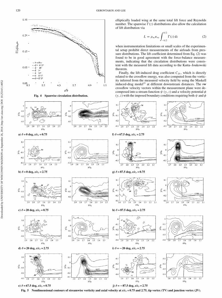
Fig. 5 Nondimensional contours of streamwise vorticity and axial velocity at x/cr = 0.75 and 2.75, tip vortex (TV) and junction vortex (JV).
elliptically loaded wing at the same total lift force and Reynoldsnumber. The spanwise �(z) distributions also allow the calculationof lift distribution via
L = ρ∞u∞
∫ b/2
−b/2
�(z) dz (2)
when instrumentation limitations or small scales of the experimen-tal setup prohibit direct measurements of the airloads from pres-sure distributions. The lift coefficient determined from Eq. (2) wasfound to be in good agreement with the force-balance measure-ments, indicating that the circulation distributions were consis-tent with the measured lift data according to the Kutta–Joukowskitheorem.
Finally, the lift-induced drag coefficient CDi , which is directlyrelated to the crossflow energy, was also computed from the vortic-ity inferred from the measured velocity field by using the Maskellinduced-drag model15 at different downstream distances. The vwcrossflow velocity vectors within the measurement plane were de-composed into a stream function ψ (y, z) and a velocity potential φ(y, z) with the imposed boundary conditions requiring both ψ and φ
Dow
nloa
ded
by U
NIV
ER
SIT
Y O
F W
ISC
ON
SIN
MA
DIS
ON
on
Sept
embe
r 26
, 201
4 | h
ttp://
arc.
aiaa
.org
| D
OI:
10.
2514
/1.1
4052
GERONTAKOS AND LEE 121
to be zero on the edges of the measurement plane. The lift-induceddrag Di was then obtained by
Di = 1
2ρ∞
∫∫Sζ
ψζ dy dz − 1
2ρ∞
∫∫S1
φσ dy dz (3)
where ζ is the vorticity, the surface Sζ is the region within S1where the vorticity is nonzero, σ(=∂v/∂y + ∂w/∂z) is a sourceterm, and the flow is incompressible. CDi of 0.021 was observedfor x /cr = 2.75. CDi values were also estimated from the followingPrandtl’s inviscid, incompressible lifting-line equation:
Di = L sin αi = L sin αi (z0) = 1
4πU∞
∫ b/2
−b/2
[(d�/dz) dz
z − z0
]· L
(4)
a)
b)
c)
d)
e)
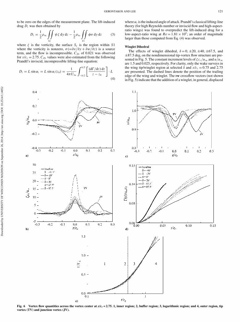
Fig. 6 Vortex flow quantities across the vortex center at x/cr = 2.75. 1, inner region; 2, buffer region; 3, logarithmic region; and 4, outer region, tipvortex (TV) and junction vortex (JV).
whereαi is the induced angle of attack. Prandtl’s classical lifting-linetheory (for high Reynolds number or inviscid flow and high-aspect-ratio wings) was found to overpredict the lift-induced drag for alow-aspect-ratio wing at Re = 1.81 × 10⁵; an order of magnitudelarger than those computed from Eq. (4) was observed.
Winglet DihedralThe effects of winglet dihedral, δ = 0, ±20, ±40, ±67.5, and
±87.5 deg, on the nondimensional tip-vortex flow structure are pre-sented in Fig. 5. The constant increment levels of ζcr/u∞ and u/u∞are 1.5 and 0.025, respectively. For clarity, only the wake surveys inthe wing tip/winglet region at selected δ and x /cr = 0.75 and 2.75are presented. The dashed lines denote the position of the trailingedge of the wing and winglet. The vw crossflow vectors (not shownin Fig. 5) indicate that the addition of a winglet, in general, displaced
Dow
nloa
ded
by U
NIV
ER
SIT
Y O
F W
ISC
ON
SIN
MA
DIS
ON
on
Sept
embe
r 26
, 201
4 | h
ttp://
arc.
aiaa
.org
| D
OI:
10.
2514
/1.1
4052
122 GERONTAKOS AND LEE
a)
b)
c)
d)
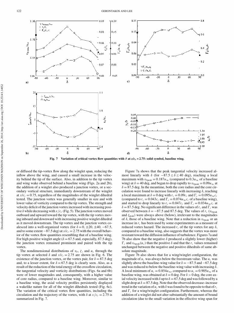
Fig. 7 Variation of critical vortex flow quantities with δ at x/cr = 2.75: solid symbol, baseline wing.
or diffused the tip-vortex flow along the winglet span, reducing theinflow above the wing, and caused a small increase in the veloc-ity behind the tip of the surface. Also, in addition to the tip vortexand wing wake observed behind a baseline wing (Figs. 2a and 2b),the addition of a winglet also produced a junction vortex, or a sec-ondary vortical structure, immediately downstream of the wingletat x /cr = 0.75, regardless of the magnitudes of the winglet dihedraltested. The junction vortex was generally smaller in size and withlower value of vorticity compared to the tip vortex. The strength andvelocity deficit of the junction vortex increased with increasing posi-tive δ while decreasing with x/cr (Fig. 5). The junction vortex movedoutboard and upward toward the tip vortex, with the tip vortex mov-ing inboard and downward with increasing positive winglet dihedralas it moved downstream. The tip vortex and the junction vortex co-alesced into a well-organized vortex (for δ = 0, ±20, ±40, −67.5,and to some extent −87.5 deg) at x /cr = 2.75 with the overall behav-ior of the vortex flow quantities resembling that of a baseline wing.For high positive winglet angle (δ = 67.5 and, especially, 87.5 deg),the junction vortex remained prominent and paired with the tipvortex.
The nondimensional distributions of vθ , ζ , and uc through thetip vortex at selected δ and x /cr = 2.75 are shown in Fig. 6. Theexistence of the junction vortex, or the vortex pair, for δ = 87.5 degand, to a lesser extent, for δ = 67.5 deg is clearly seen. Also, as aresult of the reduction of the total energy of the crossflow circulation,the tangential velocity and vorticity distributions (Figs. 6a and 6b)were of lower magnitudes and, consequently, with a higher valueof core radius, compared to a baseline wing. Moreover, similar toa baseline wing, the axial velocity profiles persistently displayeda wakelike nature for all of the winglet dihedrals tested (Fig. 6c).The variation of the critical vortex flow quantities, including thecirculation and the trajectory of the vortex, with δ at x/cr = 2.75 issummarized in Fig. 7.
Figure 7a shows that the peak tangential velocity increased al-most linearly with δ (for −87.5 ≤ δ ≤ 40 deg), reaching a localmaximum with vθpeak = 0.187u∞ (compared to 0.3u∞ of a baselinewing) at δ = 40 deg, and began to drop rapidly to vθpeak = 0.09u∞ atδ = 87.5 deg. In the meantime, both the core radius and the core cir-culation were found to increase linearly with increasing δ, reachinga local maximum at δ = 0 deg with rc = 0.09cr and �c = 0.095u∞cr(compared to rc = 0.043cr and �c = 0.074u∞cr of a baseline wing),and started to drop linearly to rc = 0.047cr and �c = 0.034u∞cr atδ = 87.5 deg. No significant difference in the values of rc and �c wasobserved between δ = −87.5 and 87.5 deg. The values of rc (vθpeak
and ζpeak) were always above (below), irrelevant to the magnitudesof δ, those of a baseline wing. Note that a reduction in vθpeak or anincrease in rc has been used by some experimenters as a measure ofreduced vortex hazard. The increased rc of the tip vortex for any δ,compared to a baseline wing, also suggests that the vortex was moreresistant toward the diffusion influence of turbulence. Figures 7a and7b also show that the negative δ produced a slightly lower (higher)�c and vθpeak(uc) than the positive δ and that the rc values remainedunchanged between the negative and positive dihedrals of same ab-solute magnitude.
Figure 7b also shows that for a wing/winglet configuration, themagnitude of uc was always below the freestream value. The uc wasslightly above the baseline-wing value for δ = −87.5 and −67.5 degand was reduced to below the baseline-wing value with increasing δ.A local minimum of uc = 0.854u∞, compared to uc = 0.905u∞ of abaseline wing, was obtained at δ = 0 deg. For δ > 0 deg, the core ax-ial velocity increased with δ up to δ = 67.5 deg and was followed by aslight drop at δ = 87.5 deg. Note that the observed decrease–increasetrend in the variation of uc with δ was found to be opposite to that of rcand �c for a wing/winglet configuration. Furthermore, whereas theaddition of a winglet did not alter substantially the amount of boundcirculation (due to the small variation in the effective wing span for
Dow
nloa
ded
by U
NIV
ER
SIT
Y O
F W
ISC
ON
SIN
MA
DIS
ON
on
Sept
embe
r 26
, 201
4 | h
ttp://
arc.
aiaa
.org
| D
OI:
10.
2514
/1.1
4052
GERONTAKOS AND LEE 123
a same lift coefficient condition), as is shown in Fig. 7c, however,it varied the spanwise �(z) distributions (Fig. 4), moving the centerof vorticity further outboard along the span (Fig. 7d). On the otherhand, the total circulation of the vortex was found to increase dras-tically with δ for −87.5 ≤ δ ≤ −40 deg, and reached a rather con-stant value, comparable to that of a baseline wing, for −40 ≤ δ ≤87.5 deg.
The behavior of the spanwise �(z) and radial �(r) distributionsand the inner-flow self-similarity of the tip vortex at different δfor x /cr = 2.75 are presented in Figs. 4, 6d, and 6e, respectively.Figure 4 indicates that the �(z) distribution near the tip was moregradual with decreasing δ and shifted farther inboard (except forδ = 87.5 deg, which exhibited the most precipitous dip near thetip), compared to a baseline wing. Also, the �(r) level was foundto significantly decrease below the baseline-wing value for a wingwith a winglet (Fig. 6d). Note the significant reduction in the �(r)distribution at δ = 87.5 deg. Furthermore, when �(r)/�c is plottedagainst log(r/rc), the inner region of the tip vortex in the near fieldbehind a swept and tapered wing with and without a winglet alsoexhibits some interesting characteristics (Fig. 6e). The distributionof �(r) within the tip vortex core followed an � ∝ r 2 profile forr/rc < 0.4 and varied logarithmically for 0.5 < r/rc < 1.4, a phe-nomenon similar to that of a square-tipped rectangular wing.11,16
For r/rc > 1.4, � continued to vary with x /cr , suggesting that atr > 1.4rc, the rollup of the inner region of the vortex was onlynearly complete and that there was a slow addition of vorticity tothe outer layers of the vortex from the shear layer arriving fromthe inboard regions. The empirical curve-fit relationships that de-scribe the inner-core region and the region where the �(r) distri-bution is logarithmic, according to Hoffmann and Joubert17 andPhillips,18 are
�(r)/�c = A(r/rc)2 for r/rc < 0.4 (5)
�(r)/�c = B log(r/rc) + C for 0.5 < r/rc < 1.4 (6)
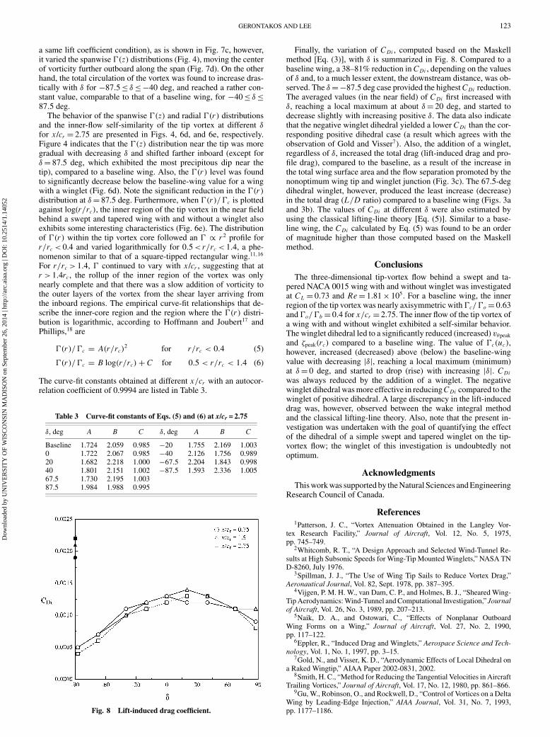
The curve-fit constants obtained at different x/cr with an autocor-relation coefficient of 0.9994 are listed in Table 3.
Table 3 Curve-fit constants of Eqs. (5) and (6) at x/cr = 2.75
δ, deg A B C δ, deg A B C
Baseline 1.724 2.059 0.985 −20 1.755 2.169 1.0030 1.722 2.067 0.985 −40 2.126 1.756 0.98920 1.682 2.218 1.000 −67.5 2.204 1.843 0.99840 1.801 2.151 1.002 −87.5 1.593 2.336 1.00567.5 1.730 2.195 1.00387.5 1.984 1.988 0.995
Fig. 8 Lift-induced drag coefficient.
Finally, the variation of CDi , computed based on the Maskellmethod [Eq. (3)], with δ is summarized in Fig. 8. Compared to abaseline wing, a 38–81% reduction in CDi , depending on the valuesof δ and, to a much lesser extent, the downstream distance, was ob-served. The δ = −87.5 deg case provided the highest CDi reduction.The averaged values (in the near field) of CDi first increased withδ, reaching a local maximum at about δ = 20 deg, and started todecrease slightly with increasing positive δ. The data also indicatethat the negative winglet dihedral yielded a lower CDi than the cor-responding positive dihedral case (a result which agrees with theobservation of Gold and Visser7). Also, the addition of a winglet,regardless of δ, increased the total drag (lift-induced drag and pro-file drag), compared to the baseline, as a result of the increase inthe total wing surface area and the flow separation promoted by thenonoptimum wing tip and winglet junction (Fig. 3c). The 67.5-degdihedral winglet, however, produced the least increase (decrease)in the total drag (L/D ratio) compared to a baseline wing (Figs. 3aand 3b). The values of CDi at different δ were also estimated byusing the classical lifting-line theory [Eq. (5)]. Similar to a base-line wing, the CDi calculated by Eq. (5) was found to be an orderof magnitude higher than those computed based on the Maskellmethod.
ConclusionsThe three-dimensional tip-vortex flow behind a swept and ta-
pered NACA 0015 wing with and without winglet was investigatedat CL = 0.73 and Re = 1.81 × 10⁵. For a baseline wing, the innerregion of the tip vortex was nearly axisymmetric with �c/�o = 0.63and �o/�b = 0.4 for x/cr = 2.75. The inner flow of the tip vortex ofa wing with and without winglet exhibited a self-similar behavior.The winglet dihedral led to a significantly reduced (increased) vθpeak
and ζpeak(rc) compared to a baseline wing. The value of �c(uc),however, increased (decreased) above (below) the baseline-wingvalue with decreasing |δ|, reaching a local maximum (minimum)at δ = 0 deg, and started to drop (rise) with increasing |δ|. CDiwas always reduced by the addition of a winglet. The negativewinglet dihedral was more effective in reducing CDi compared to thewinglet of positive dihedral. A large discrepancy in the lift-induceddrag was, however, observed between the wake integral methodand the classical lifting-line theory. Also, note that the present in-vestigation was undertaken with the goal of quantifying the effectof the dihedral of a simple swept and tapered winglet on the tip-vortex flow; the winglet of this investigation is undoubtedly notoptimum.
AcknowledgmentsThis work was supported by the Natural Sciences and Engineering
Research Council of Canada.
References1Patterson, J. C., “Vortex Attenuation Obtained in the Langley Vor-
tex Research Facility,” Journal of Aircraft, Vol. 12, No. 5, 1975,pp. 745–749.
2Whitcomb, R. T., “A Design Approach and Selected Wind-Tunnel Re-sults at High Subsonic Speeds for Wing-Tip Mounted Winglets,” NASA TND-8260, July 1976.
3Spillman, J. J., “The Use of Wing Tip Sails to Reduce Vortex Drag,”Aeronautical Journal, Vol. 82, Sept. 1978, pp. 387–395.
4Vijgen, P. M. H. W., van Dam, C. P., and Holmes, B. J., “Sheared Wing-Tip Aerodynamics: Wind-Tunnel and Computational Investigation,” Journalof Aircraft, Vol. 26, No. 3, 1989, pp. 207–213.
5Naik, D. A., and Ostowari, C., “Effects of Nonplanar OutboardWing Forms on a Wing,” Journal of Aircraft, Vol. 27, No. 2, 1990,pp. 117–122.
6Eppler, R., “Induced Drag and Winglets,” Aerospace Science and Tech-nology, Vol. 1, No. 1, 1997, pp. 3–15.
7Gold, N., and Visser, K. D., “Aerodynamic Effects of Local Dihedral ona Raked Wingtip,” AIAA Paper 2002-0831, 2002.
8Smith, H. C., “Method for Reducing the Tangential Velocities in AircraftTrailing Vortices,” Journal of Aircraft, Vol. 17, No. 12, 1980, pp. 861–866.
9Gu, W., Robinson, O., and Rockwell, D., “Control of Vortices on a DeltaWing by Leading-Edge Injection,” AIAA Journal, Vol. 31, No. 7, 1993,pp. 1177–1186.
Dow
nloa
ded
by U
NIV
ER
SIT
Y O
F W
ISC
ON
SIN
MA
DIS
ON
on
Sept
embe
r 26
, 201
4 | h
ttp://
arc.
aiaa
.org
| D
OI:
10.
2514
/1.1
4052
124 GERONTAKOS AND LEE
10Wenger, C. W., and Devenport, W. J., “Seven-Hole Pressure Probe Cal-ibration Utilizing Look-Up Error Tables,” AIAA Journal, Vol. 37, No. 6,1999, pp. 675–679.
11Birch, D., Lee, T., Mokhtarian, F., and Kafyeke, F., “Structure andInduced Drag of a Tip Vortex,” Journal of Aircraft, Vol. 41, No. 5, 2004,pp. 1138–1145.
12Chow, J. S., Zilliac, G. G., and Bradshaw, P., “Mean and TurbulenceMeasurements in the Near Field of a Wingtip Vortex,” AIAA Journal, Vol. 35,No. 10, 1997, pp. 1561–1567.
13Lamb, H., Hydrodynamics, 6th ed., Dover, New York, 1945, p. 592.14Glauert, T. H., The Elements of Airfoil and Airscrew Theory, Cambridge
Univ. Press, London, 1926.15Maskell, E., “Progress Towards a Method for the Measurement of the
Components of the Drag of a Wing of Finite Span,” Royal Aircraft Estab-lishment, RAE Technical Rept. 72232, 1973.
16Ramaprian, B. R., and Zheng, Y., “Measurements in Rollup Region ofthe Tip Vortex from a Rectangular Wing,” AIAA Journal, Vol. 35, No. 12,1997, pp. 1837–1843.
17Hoffmann, E. R., and Joubert, P. N., “Turbulent Line Vortices,” Journalof Fluid Mechanics, Vol. 16, 1963, pp. 395–411.
18Phillips, W. R. C., “The Turbulent Trailing Vortex During Roll-Up,”Journal of Fluid Mechanics, Vol. 105, 1981, pp. 451–467.
Dow
nloa
ded
by U
NIV
ER
SIT
Y O
F W
ISC
ON
SIN
MA
DIS
ON
on
Sept
embe
r 26
, 201
4 | h
ttp://
arc.
aiaa
.org
| D
OI:
10.
2514
/1.1
4052