Embed Size (px)
Citation preview
EIO0000000051 6/2010
EIO
0000
0000
51.0
1
www.schneider-electric.com
Advantys STBStandard Dual Port Ethernet Modbus TCP/IP Network Interface ModuleApplications Guide
6/2010

The information provided in this documentation contains general descriptions and/or technical characteristics of the performance of the products contained herein. This documentation is not intended as a substitute for and is not to be used for determining suitability or reliability of these products for specific user applications. It is the duty of any such user or integrator to perform the appropriate and complete risk analysis, evaluation and testing of the products with respect to the relevant specific application or use thereof. Neither Schneider Electric nor any of its affiliates or subsidiaries shall be responsible or liable for misuse of the information contained herein. If you have any suggestions for improvements or amendments or have found errors in this publication, please notify us.
No part of this document may be reproduced in any form or by any means, electronic or mechanical, including photocopying, without express written permission of Schneider Electric.
All pertinent state, regional, and local safety regulations must be observed when installing and using this product. For reasons of safety and to help ensure compliance with documented system data, only the manufacturer should perform repairs to components.
When devices are used for applications with technical safety requirements, the relevant instructions must be followed.
Failure to use Schneider Electric software or approved software with our hardware products may result in injury, harm, or improper operating results.
Failure to observe this information can result in injury or equipment damage.
© 2010 Schneider Electric. All rights reserved.
2 EIO0000000051 6/2010

Table of Contents
Safety Information . . . . . . . . . . . . . . . . . . . . . . . . . . . . . . 7About the Book . . . . . . . . . . . . . . . . . . . . . . . . . . . . . . . . . 9
Chapter 1 Introduction. . . . . . . . . . . . . . . . . . . . . . . . . . . . . . . . . . . . 13What Is a Network Interface Module? . . . . . . . . . . . . . . . . . . . . . . . . . . . . 14What Is Advantys STB? . . . . . . . . . . . . . . . . . . . . . . . . . . . . . . . . . . . . . . 16Overview of the STB NIP 2311 Product . . . . . . . . . . . . . . . . . . . . . . . . . . 20Introduction to Ethernet Connectivity . . . . . . . . . . . . . . . . . . . . . . . . . . . . 22
Chapter 2 Physical Description of the STB NIP 2311 NIM Module 23External Features of the STB NIP 2311 NIM . . . . . . . . . . . . . . . . . . . . . . 24STB NIP 2311 Ethernet Interfaces . . . . . . . . . . . . . . . . . . . . . . . . . . . . . . 25STB NIP 2311 Rotary Switches . . . . . . . . . . . . . . . . . . . . . . . . . . . . . . . . 27STB NIP 2311 LED Indicators. . . . . . . . . . . . . . . . . . . . . . . . . . . . . . . . . . 29Advantys STB Island Status LEDs . . . . . . . . . . . . . . . . . . . . . . . . . . . . . . 31The CFG Interface. . . . . . . . . . . . . . . . . . . . . . . . . . . . . . . . . . . . . . . . . . . 33The Power Supply Interface . . . . . . . . . . . . . . . . . . . . . . . . . . . . . . . . . . . 35Logic Power. . . . . . . . . . . . . . . . . . . . . . . . . . . . . . . . . . . . . . . . . . . . . . . . 36Selecting a Source Power Supply for the Island’s Logic Power Bus. . . . . 38STB NIP 2311 Module Specifications . . . . . . . . . . . . . . . . . . . . . . . . . . . . 41
Chapter 3 How to Configure the Island . . . . . . . . . . . . . . . . . . . . . . 433.1 Understanding Island Bus Addresses . . . . . . . . . . . . . . . . . . . . . . . . . . . . 44
How Do Modules Automatically Get Island Bus Addresses? . . . . . . . . . . 443.2 Autoconfiguring Island Parameters . . . . . . . . . . . . . . . . . . . . . . . . . . . . . . 47
How to Auto-Configure Default Parameters for Island Modules . . . . . . . . 48What is the RST Button?. . . . . . . . . . . . . . . . . . . . . . . . . . . . . . . . . . . . . . 49How to Overwrite Flash Memory with the RST Button . . . . . . . . . . . . . . . 50
3.3 Using a Removable Memory Card to Configure the Island . . . . . . . . . . . . 52How to Install the STB XMP 4440 Optional Removable Memory Card. . . 53Using the STB XMP 4440 Optional Removable Memory Card to Configure the Island . . . . . . . . . . . . . . . . . . . . . . . . . . . . . . . . . . . . . . . . . 56
EIO0000000051 6/2010 3

3.4 Configuring the STB NIP 2311 NIM with the Advantys Configuration Software. . . . . . . . . . . . . . . . . . . . . . . . . . . . . . . . . . . . . . . . . . . . . . . . . . 59Setting the Size and Display Format of HMI-to-PLC and PLC-to-HMI Tables . . . . . . . . . . . . . . . . . . . . . . . . . . . . . . . . . . . . . . . . . . . . . . . . . . . 60Ethernet Parameters - The IP Address Tab. . . . . . . . . . . . . . . . . . . . . . . 62Ethernet Parameters - Master IP Configuration. . . . . . . . . . . . . . . . . . . . 64Ethernet Parameters - SNMP Agent Functionality. . . . . . . . . . . . . . . . . . 66RSTP and Redundancy . . . . . . . . . . . . . . . . . . . . . . . . . . . . . . . . . . . . . . 68Configuring Module Options . . . . . . . . . . . . . . . . . . . . . . . . . . . . . . . . . . 70
Chapter 4 How to Obtain IP Parameters for the STB NIP 2311 . . . . 73How Does the STB NIP 2311 Obtain IP Parameters?. . . . . . . . . . . . . . . 74The IP Address Assignment Flowchart . . . . . . . . . . . . . . . . . . . . . . . . . . 76
Chapter 5 Optimizing Performance . . . . . . . . . . . . . . . . . . . . . . . . . . 795.1 Selecting a Switch . . . . . . . . . . . . . . . . . . . . . . . . . . . . . . . . . . . . . . . . . . 80
Role of a Switch in an Ethernet Network . . . . . . . . . . . . . . . . . . . . . . . . . 81Transmission Speed, Duplex and Auto-Negotiation . . . . . . . . . . . . . . . . 82Quality of Service (QoS) . . . . . . . . . . . . . . . . . . . . . . . . . . . . . . . . . . . . . 83IGMP Snooping . . . . . . . . . . . . . . . . . . . . . . . . . . . . . . . . . . . . . . . . . . . . 84Rapid Spanning Tree Protocol (RSTP) . . . . . . . . . . . . . . . . . . . . . . . . . . 85Virtual Local Area Network (VLAN) . . . . . . . . . . . . . . . . . . . . . . . . . . . . . 86Port Mirroring . . . . . . . . . . . . . . . . . . . . . . . . . . . . . . . . . . . . . . . . . . . . . . 88Simple Network Management Protocol (SNMP) Agent . . . . . . . . . . . . . . 90
5.2 Control Application Design. . . . . . . . . . . . . . . . . . . . . . . . . . . . . . . . . . . . 91Message Types . . . . . . . . . . . . . . . . . . . . . . . . . . . . . . . . . . . . . . . . . . . . 92Message Connection Types . . . . . . . . . . . . . . . . . . . . . . . . . . . . . . . . . . 94TCP and CIP Connections. . . . . . . . . . . . . . . . . . . . . . . . . . . . . . . . . . . . 96Message Priority . . . . . . . . . . . . . . . . . . . . . . . . . . . . . . . . . . . . . . . . . . . 97Messaging Performance . . . . . . . . . . . . . . . . . . . . . . . . . . . . . . . . . . . . . 98Message Frequency . . . . . . . . . . . . . . . . . . . . . . . . . . . . . . . . . . . . . . . . 99Allocating Network Bandwidth . . . . . . . . . . . . . . . . . . . . . . . . . . . . . . . . . 101Estimating Message Traverse and Response Times . . . . . . . . . . . . . . . 103
5.3 Projecting Ethernet Network Performance. . . . . . . . . . . . . . . . . . . . . . . . 105Network Load and Bandwidth Calculation Example . . . . . . . . . . . . . . . . 105
Chapter 6 Replacing the STB NIP 2311 NIM . . . . . . . . . . . . . . . . . . . 109Replacing the STB NIP 2311 Module . . . . . . . . . . . . . . . . . . . . . . . . . . . 109
Chapter 7 STB NIP 2311 Services . . . . . . . . . . . . . . . . . . . . . . . . . . . 1137.1 Modbus Messaging . . . . . . . . . . . . . . . . . . . . . . . . . . . . . . . . . . . . . . . . . 114
Modbus Messaging Service Description . . . . . . . . . . . . . . . . . . . . . . . . . 115Data Exchange with the STB NIP 2311. . . . . . . . . . . . . . . . . . . . . . . . . . 120Reading Diagnostic Data . . . . . . . . . . . . . . . . . . . . . . . . . . . . . . . . . . . . . 129Modbus Commands Supported by the STB NIP 2311 NIM. . . . . . . . . . . 137Modbus Exception Responses . . . . . . . . . . . . . . . . . . . . . . . . . . . . . . . . 141
7.2 Server-Assigned IP Parameters . . . . . . . . . . . . . . . . . . . . . . . . . . . . . . . 142Assignment of IP Parameters from a Server . . . . . . . . . . . . . . . . . . . . . . 142
4 EIO0000000051 6/2010

7.3 Embedded Web Pages . . . . . . . . . . . . . . . . . . . . . . . . . . . . . . . . . . . . . . . 143Browser Requirements for the STB NIP 2311 Embedded Web Pages. . . 144Accessing the STB NIP 2311 Embedded Web Pages . . . . . . . . . . . . . . . 145Navigating the STB NIP 2311 Embedded Web Pages . . . . . . . . . . . . . . . 146STB NIP 2311 Home Page . . . . . . . . . . . . . . . . . . . . . . . . . . . . . . . . . . . . 147The About Page . . . . . . . . . . . . . . . . . . . . . . . . . . . . . . . . . . . . . . . . . . . . 148The Change Password Page . . . . . . . . . . . . . . . . . . . . . . . . . . . . . . . . . . 149The IP Configuration Page . . . . . . . . . . . . . . . . . . . . . . . . . . . . . . . . . . . . 150The Ethernet Ports Configuration Page . . . . . . . . . . . . . . . . . . . . . . . . . . 152The Master IP Configuration Page . . . . . . . . . . . . . . . . . . . . . . . . . . . . . . 154The RSTP Configuration Page . . . . . . . . . . . . . . . . . . . . . . . . . . . . . . . . . 157RSTP Bridge Statistics . . . . . . . . . . . . . . . . . . . . . . . . . . . . . . . . . . . . . . . 158RSTP Port Statistics . . . . . . . . . . . . . . . . . . . . . . . . . . . . . . . . . . . . . . . . . 160Modbus Registers that Correspond to Port and Bridge Statistics . . . . . . . 161The SNMP Agent Configuration Page. . . . . . . . . . . . . . . . . . . . . . . . . . . . 162The Modbus I/O Data Values Page. . . . . . . . . . . . . . . . . . . . . . . . . . . . . . 164The Island Configuration Page . . . . . . . . . . . . . . . . . . . . . . . . . . . . . . . . . 166The Island Parameters Page. . . . . . . . . . . . . . . . . . . . . . . . . . . . . . . . . . . 167The Ethernet TCP/IP Statistics Page . . . . . . . . . . . . . . . . . . . . . . . . . . . . 169The Ethernet Port Statistics Page . . . . . . . . . . . . . . . . . . . . . . . . . . . . . . . 170The TCP Port Statistics Page . . . . . . . . . . . . . . . . . . . . . . . . . . . . . . . . . . 172The SNMP Statistics Page . . . . . . . . . . . . . . . . . . . . . . . . . . . . . . . . . . . . 174The Log File Page. . . . . . . . . . . . . . . . . . . . . . . . . . . . . . . . . . . . . . . . . . . 175The Reboot Page . . . . . . . . . . . . . . . . . . . . . . . . . . . . . . . . . . . . . . . . . . . 177The Support Page . . . . . . . . . . . . . . . . . . . . . . . . . . . . . . . . . . . . . . . . . . . 178
7.4 SNMP Services . . . . . . . . . . . . . . . . . . . . . . . . . . . . . . . . . . . . . . . . . . . . . 179MIB II . . . . . . . . . . . . . . . . . . . . . . . . . . . . . . . . . . . . . . . . . . . . . . . . . . . . . 180SNMP Device Management . . . . . . . . . . . . . . . . . . . . . . . . . . . . . . . . . . . 197Configuring the SNMP Agent . . . . . . . . . . . . . . . . . . . . . . . . . . . . . . . . . . 199About the Schneider Private MIBs . . . . . . . . . . . . . . . . . . . . . . . . . . . . . . 200MIB Subtree Description . . . . . . . . . . . . . . . . . . . . . . . . . . . . . . . . . . . . . . 202Port 502 Messaging Subtree Description . . . . . . . . . . . . . . . . . . . . . . . . . 203Web MIB Subtree . . . . . . . . . . . . . . . . . . . . . . . . . . . . . . . . . . . . . . . . . . . 204Equipment Profile Subtree . . . . . . . . . . . . . . . . . . . . . . . . . . . . . . . . . . . . 205
Chapter 8 Connecting an Advantys STB Island to a Quantum Master Using Unity Pro . . . . . . . . . . . . . . . . . . 207About This Connection Example . . . . . . . . . . . . . . . . . . . . . . . . . . . . . . . . 208How to Configure Unity Pro to Use Advantys Island I/O Data. . . . . . . . . . 211How to Set Up RTP and HMI to PLC Communications. . . . . . . . . . . . . . . 219How to Enable RSTP . . . . . . . . . . . . . . . . . . . . . . . . . . . . . . . . . . . . . . . . 222How to Store an Island Configuration in a Removable Memory Card. . . . 224
EIO0000000051 6/2010 5

Chapter 9 Advanced Configuration Features . . . . . . . . . . . . . . . . . . 225Configurable Parameters for the STB NIP 2311 . . . . . . . . . . . . . . . . . . . 226Configuring Mandatory Modules . . . . . . . . . . . . . . . . . . . . . . . . . . . . . . . 227Prioritizing a Module . . . . . . . . . . . . . . . . . . . . . . . . . . . . . . . . . . . . . . . . 229What Is a Reflex Action? . . . . . . . . . . . . . . . . . . . . . . . . . . . . . . . . . . . . . 230Island Fallback Scenarios . . . . . . . . . . . . . . . . . . . . . . . . . . . . . . . . . . . . 234Saving Configuration Data. . . . . . . . . . . . . . . . . . . . . . . . . . . . . . . . . . . . 236A Modbus View of the Island’s Data Image . . . . . . . . . . . . . . . . . . . . . . . 237Write-Protecting Configuration Data . . . . . . . . . . . . . . . . . . . . . . . . . . . . 240The Island’s Process Image Blocks. . . . . . . . . . . . . . . . . . . . . . . . . . . . . 241The HMI Blocks in the Island Data Image . . . . . . . . . . . . . . . . . . . . . . . . 243Test Mode . . . . . . . . . . . . . . . . . . . . . . . . . . . . . . . . . . . . . . . . . . . . . . . . 245Run-Time Parameters . . . . . . . . . . . . . . . . . . . . . . . . . . . . . . . . . . . . . . . 247Virtual Placeholder. . . . . . . . . . . . . . . . . . . . . . . . . . . . . . . . . . . . . . . . . . 251
Glossary . . . . . . . . . . . . . . . . . . . . . . . . . . . . . . . . . . . . . . . . . . . 253Index . . . . . . . . . . . . . . . . . . . . . . . . . . . . . . . . . . . . . . . . . . . 277
6 EIO0000000051 6/2010

§
Safety InformationImportant Information
NOTICE
Read these instructions carefully, and look at the equipment to become familiar with the device before trying to install, operate, or maintain it. The following special messages may appear throughout this documentation or on the equipment to warn of potential hazards or to call attention to information that clarifies or simplifies a procedure.
EIO0000000051 6/2010 7

PLEASE NOTE
Electrical equipment should be installed, operated, serviced, and maintained only by qualified personnel. No responsibility is assumed by Schneider Electric for any consequences arising out of the use of this material.
A qualified person is one who has skills and knowledge related to the construction and operation of electrical equipment and the installation, and has received safety training to recognize and avoid the hazards involved.
8 EIO0000000051 6/2010
About the Book
At a Glance
Document Scope
This book describes the STB NIP 2311 Dual Port Ethernet Modbus TCP/IP network interface module (NIM). The STB NIP 2311 can communicate with a fieldbus master over Ethernet. The NIM represents the island configuration as a single node on an Ethernet network. This guide includes the NIM’s:
role in an Ethernet networkcapabilities as the gateway to the Advantys STB islandexternal and internal interfacesflash memory and removable memoryintegrated power supplyauto-configuration capabilityconfiguration data storageisland bus scanning functionalitydata exchange capabilitiesdiagnostic messagesspecifications
The dual-port configuration has two important advantages:supports a daisy chain topologyprovides two paths to the network in a daisy chain loop
EIO0000000051 6/2010 9
Validity Note
This document is valid for Advantys 5.0 or later.
The technical characteristics of the device(s) described in this manual also appear online. To access this information online:
The characteristics presented in this manual should be the same as those that appear online. In line with our policy of constant improvement we may revise content over time to improve clarity and accuracy. In the event that you see a difference between the manual and online information, use the online information as your reference.
Related Documents
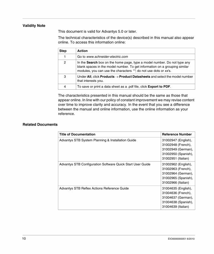
Step Action
1 Go to www.schneider-electric.com
2 In the Search box on the home page, type a model number. Do not type any blank spaces in the model number. To get information on a grouping similar modules, you can use the characters **; do not use dots or xx's.
3 Under All, click Products → Product Datasheets and select the model number that interests you.
4 To save or print a data sheet as a .pdf file, click Export to PDF.
Title of Documentation Reference Number
Advantys STB System Planning & Installation Guide 31002947 (English), 31002948 (French), 31002949 (German), 31002950 (Spanish), 31002951 (Italian)
Advantys STB Configuration Software Quick Start User Guide 31002962 (English), 31002963 (French), 31002964 (German), 31002965 (Spanish), 31002966 (Italian)
Advantys STB Reflex Actions Reference Guide 31004635 (English), 31004636 (French), 31004637 (German), 31004638 (Spanish), 31004639 (Italian)
10 EIO0000000051 6/2010
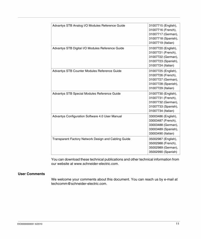
You can download these technical publications and other technical information from our website at www.schneider-electric.com.
User Comments
We welcome your comments about this document. You can reach us by e-mail at [email protected].
Advantys STB Analog I/O Modules Reference Guide 31007715 (English), 31007716 (French), 31007717 (German), 31007718 (Spanish), 31007719 (Italian)
Advantys STB Digital I/O Modules Reference Guide 31007720 (English), 31007721 (French), 31007722 (German), 31007723 (Spanish), 31007724 (Italian)
Advantys STB Counter Modules Reference Guide 31007725 (English), 31007726 (French), 31007727 (German), 31007728 (Spanish), 31007729 (Italian)
Advantys STB Special Modules Reference Guide 31007730 (English), 31007731 (French), 31007732 (German), 31007733 (Spanish), 31007734 (Italian)
Advantys Configuration Software 4.0 User Manual 33003486 (English), 33003487 (French), 33003488 (German), 33003489 (Spanish), 33003490 (Italian)
Transparent Factory Network Design and Cabling Guide 35002987 (English), 35002988 (French), 35002989 (German), 35002990 (Spanish)
EIO0000000051 6/2010 11

12 EIO0000000051 6/2010
EIO0000000051 6/2010
1
Introduction
EIO0000000051 6/2010
Introduction
Introduction
This chapter describes the Advantys STB NIP 2311 Dual Port Ethernet Modbus TCP/IP network interface module (NIM) and its support for the island as an Ethernet network node. The chapter begins with an introduction of the NIM and a discussion of its role as the network adapter for the Advantys STB island. There is a brief overview of the island itself, followed by a description of the major characteristics of the Ethernet fieldbus protocol. Some information in this chapter is specific to the STB NIP 2311 and some is common to all Advantys STB NIMs.
What's in this Chapter?
This chapter contains the following topics:
Topic Page
What Is a Network Interface Module? 14
What Is Advantys STB? 16
Overview of the STB NIP 2311 Product 20
Introduction to Ethernet Connectivity 22
13
Introduction
What Is a Network Interface Module?
Purpose
Every island requires a network interface module (NIM) in the leftmost location of the primary segment. Physically, the NIM is the first (leftmost) module on the island bus. Functionally, it is the gateway to the island bus. That is, all communications to and from the island bus pass through the NIM. The NIM also has an integrated power supply that provides logic power to the island modules.
The Fieldbus Network
An island bus is a node of distributed I/O on an open fieldbus network, and the NIM is the island’s interface to that network. The NIM supports data transfers over the fieldbus network between the island and the fieldbus master.
The physical design of the NIM makes it compatible with both an Advantys STB island and your specific fieldbus master. Whereas the fieldbus connector on each NIM type may differ, the location on the module front panel is essentially the same.
Communications Roles
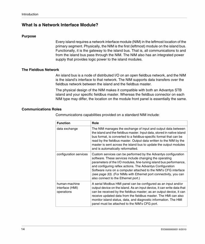
Communications capabilities provided on a standard NIM include:
Function Role
data exchange The NIM manages the exchange of input and output data between the island and the fieldbus master. Input data, stored in native island bus format, is converted to a fieldbus-specific format that can be read by the fieldbus master. Output data written to the NIM by the master is sent across the island bus to update the output modules and is automatically reformatted.
configuration services Custom services can be performed by the Advantys configuration software. These services include changing the operating parameters of the I/O modules, fine-tuning island bus performance, and configuring reflex actions. The Advantys Configuration Software runs on a computer attached to the NIM’s CFG interface (see page 33). (For NIMs with Ethernet port connectivity, you can also connect to the Ethernet port.)
human-machine interface (HMI) operations
A serial Modbus HMI panel can be configured as an input and/or output device on the island. As an input device, it can write data that can be received by the fieldbus master; as an output device, it can receive updated data from the fieldbus master. The HMI can also monitor island status, data, and diagnostic information. The HMI panel must be attached to the NIM’s CFG port.
14 EIO0000000051 6/2010
Introduction
Integrated Power Supply
The NIM’s built-in 24-to-5 VDC power supply provides logic power to the I/O modules on the primary segment of the island bus. The power supply requires a 24 VDC external power source. It converts the 24 VDC to 5 V of logic power for the island. Individual STB I/O modules in an island segment generally draw a logic bus current of between 50 and 265 mA. (Consult the Advantys STB System Planning and Installation Guide for current limitations at various operating temperatures.) If the logic bus current drawn by the I/O modules totals more than 1.2 A, additional STB power supplies need to be installed to support the load.
The NIM delivers the logic power signal to the primary segment only. Special STB XBE 1300 beginning-of-segment (BOS) modules, located in the first slot of each extension segment, have their own built-in power supplies, which provide logic power to the STB I/O modules in the extension segments. Each BOS module that you install requires 24 VDC from an external power supply.
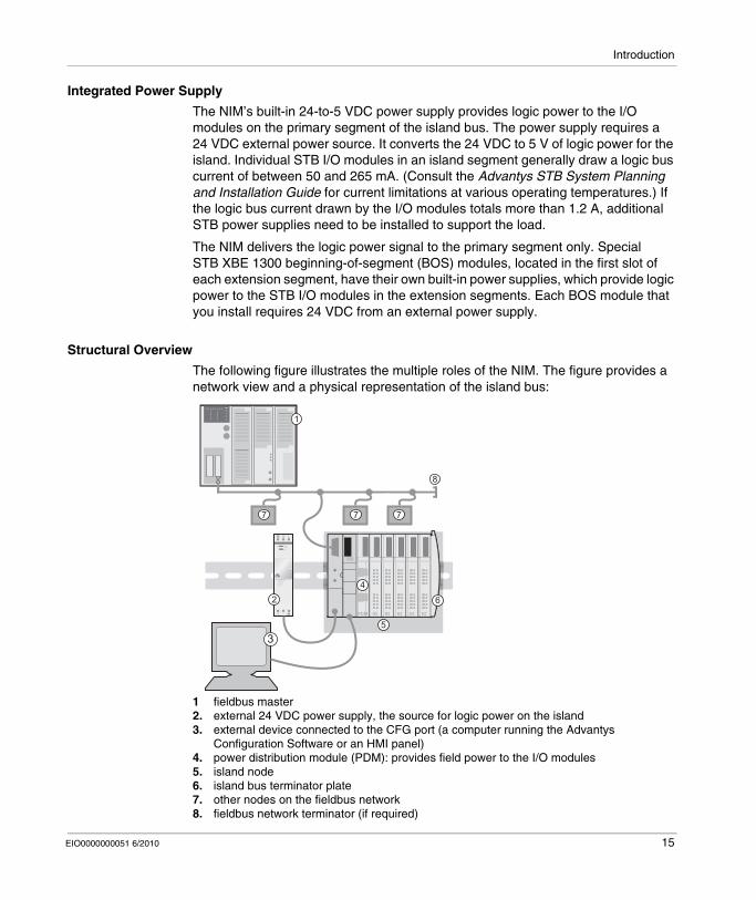
Structural Overview
The following figure illustrates the multiple roles of the NIM. The figure provides a network view and a physical representation of the island bus:
1 fieldbus master2. external 24 VDC power supply, the source for logic power on the island3. external device connected to the CFG port (a computer running the Advantys
Configuration Software or an HMI panel)4. power distribution module (PDM): provides field power to the I/O modules5. island node6. island bus terminator plate7. other nodes on the fieldbus network8. fieldbus network terminator (if required)
PDM IO IO IO IO IOPDMP M IO IO IO IO IO
1
2 6
7
8
5
4
3
7 7
EIO0000000051 6/2010 15
Introduction
What Is Advantys STB?
Introduction
Advantys STB is an assembly of distributed I/O, power, and other modules that function together as an island node on an open fieldbus network. Advantys STB delivers a highly modular and versatile slice I/O solution for the manufacturing and process industries.
Advantys STB lets you design an island of distributed I/O where the I/O modules can be installed as close as possible to the mechanical field devices that they control. This integrated concept is known as mechatronics.
Island Bus I/O
An Advantys STB island can support as many as 32 I/O modules. These modules may be Advantys STB I/O modules, preferred modules, and enhanced CANopen devices.
The Primary Segment
STB I/O modules on an island may be interconnected in groups called segments.
Every island has at least one segment, called the primary segment. It is always the first segment on the island bus. The NIM is the first module in the primary segment. The primary segment must contain at least one Advantys STB I/O module and can support a logic bus current of up to 1.2 A. The segment also contains one or more power distribution modules (PDMs), which distribute field power to the I/O modules.
16 EIO0000000051 6/2010
Introduction
Extension Segments
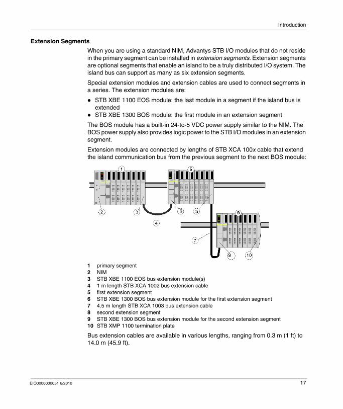
When you are using a standard NIM, Advantys STB I/O modules that do not reside in the primary segment can be installed in extension segments. Extension segments are optional segments that enable an island to be a truly distributed I/O system. The island bus can support as many as six extension segments.
Special extension modules and extension cables are used to connect segments in a series. The extension modules are:
STB XBE 1100 EOS module: the last module in a segment if the island bus is extendedSTB XBE 1300 BOS module: the first module in an extension segment
The BOS module has a built-in 24-to-5 VDC power supply similar to the NIM. The BOS power supply also provides logic power to the STB I/O modules in an extension segment.
Extension modules are connected by lengths of STB XCA 100x cable that extend the island communication bus from the previous segment to the next BOS module:
1 primary segment2 NIM3 STB XBE 1100 EOS bus extension module(s)4 1 m length STB XCA 1002 bus extension cable5 first extension segment6 STB XBE 1300 BOS bus extension module for the first extension segment7 4.5 m length STB XCA 1003 bus extension cable8 second extension segment9 STB XBE 1300 BOS bus extension module for the second extension segment10 STB XMP 1100 termination plate
Bus extension cables are available in various lengths, ranging from 0.3 m (1 ft) to 14.0 m (45.9 ft).
EIO0000000051 6/2010 17
Introduction
Preferred Modules
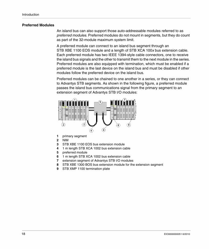
An island bus can also support those auto-addressable modules referred to as preferred modules. Preferred modules do not mount in segments, but they do count as part of the 32-module maximum system limit.
A preferred module can connect to an island bus segment through an STB XBE 1100 EOS module and a length of STB XCA 100x bus extension cable. Each preferred module has two IEEE 1394-style cable connectors, one to receive the island bus signals and the other to transmit them to the next module in the series. Preferred modules are also equipped with termination, which must be enabled if a preferred module is the last device on the island bus and must be disabled if other modules follow the preferred device on the island bus.
Preferred modules can be chained to one another in a series, or they can connect to Advantys STB segments. As shown in the following figure, a preferred module passes the island bus communications signal from the primary segment to an extension segment of Advantys STB I/O modules:
1 primary segment2 NIM3 STB XBE 1100 EOS bus extension module4 1 m length STB XCA 1002 bus extension cable5 preferred module6 1 m length STB XCA 1002 bus extension cable7 extension segment of Advantys STB I/O modules8 STB XBE 1300 BOS bus extension module for the extension segment9 STB XMP 1100 termination plate
18 EIO0000000051 6/2010
Introduction
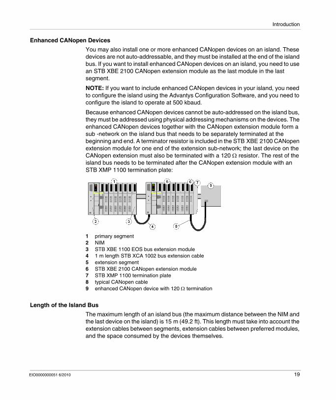
Enhanced CANopen Devices
You may also install one or more enhanced CANopen devices on an island. These devices are not auto-addressable, and they must be installed at the end of the island bus. If you want to install enhanced CANopen devices on an island, you need to use an STB XBE 2100 CANopen extension module as the last module in the last segment.
NOTE: If you want to include enhanced CANopen devices in your island, you need to configure the island using the Advantys Configuration Software, and you need to configure the island to operate at 500 kbaud.
Because enhanced CANopen devices cannot be auto-addressed on the island bus, they must be addressed using physical addressing mechanisms on the devices. The enhanced CANopen devices together with the CANopen extension module form a sub -network on the island bus that needs to be separately terminated at the beginning and end. A terminator resistor is included in the STB XBE 2100 CANopen extension module for one end of the extension sub-network; the last device on the CANopen extension must also be terminated with a 120 Ω resistor. The rest of the island bus needs to be terminated after the CANopen extension module with an STB XMP 1100 termination plate:
1 primary segment2 NIM3 STB XBE 1100 EOS bus extension module4 1 m length STB XCA 1002 bus extension cable5 extension segment6 STB XBE 2100 CANopen extension module7 STB XMP 1100 termination plate8 typical CANopen cable9 enhanced CANopen device with 120 Ω termination
Length of the Island Bus
The maximum length of an island bus (the maximum distance between the NIM and the last device on the island) is 15 m (49.2 ft). This length must take into account the extension cables between segments, extension cables between preferred modules, and the space consumed by the devices themselves.
EIO0000000051 6/2010 19
Introduction
Overview of the STB NIP 2311 Product
Introduction
An Advantys STB island bus configured with an STB NIP 2311 NIM can function as a node on an Ethernet network. The STB NIP 2311 module can be a slave device to an Ethernet host manager.
Key Features
Key features of the STB NIP 2311 Ethernet NIM:Ethernet ports:
daisy chain (low cost)daisy chain loop (lower cost, two paths to the network)
independent LED indicators for each portTransparent Ready B15 classificationcommunication with as many as 32 I/O modulesDIN rail mountingIP address assignment with standard BootP or DHCP tools512 words of data for both PLC-to-HMI and HMI-to-PLC dataconfiguration through the RS232 serial interface and Ethernetinput and output data exchanges with Ethernet messagingRS232 serial interface HMI connectivity using Modbus messagingEthernet HMI connectivity using Ethernet messagingremovable memory card for I/O configuration allows copying of the configuration dataEthernet communications at 10 or 100 Mb/s communication rate, half- or full-duplexAdvantys STB island diagnostics informationauto-configuration through either the RST button or a configuration software commandHTTP server web pagesauto MDIXSNMP capabilityphysical diagnostics (LEDs)
Ethernet and Internet Connectivity
TCP/IP is the transport layer for the Ethernet LAN on which the STB NIP 2311 Advantys STB island resides. This network architecture enables communications with a wide range of Ethernet TCP/IP control products, such as Programmable Logic Controllers (PLCs), industrial computers, motion controllers, host computers, and operator control stations.
20 EIO0000000051 6/2010
Introduction
Embedded Web Site
The STB NIP 2311 includes an embedded web site (see page 143), which is a web browser-enabled application. It allows authorized users to access configuration and diagnostic data for the STB NIP 2311 module.
Internet Applications
The STB NIP 2311 module is configured for these Internet applications:HTTP embedded web site for IP configuration and troubleshooting (see page 143)remote network management of the STB NIP 2311 module through SNMP
EIO0000000051 6/2010 21
Introduction
Introduction to Ethernet Connectivity
Introduction
The STB NIP 2311 Dual Port Ethernet Modbus TCP/IP NIM allows the Advantys STB island to function as a node on an Ethernet LAN.
Ethernet is an open local (communications) network that enables the inter-connectivity of all levels of manufacturing operations from the plant’s office to the sensors and actuators on its floor.
Conformance
The STB NIP 2311 module is located on a 100Base-T LAN. The 10/100Base-T standard is defined by the IEEE 802.3 Ethernet specification. Contention for 10/100Base-T networks is resolved by using Carrier Sense Multiple Access with Collision Detection (CSMA/CD).
Transmission Rate
An STB NIP 2311 island node resides on a baseband network with a transmission rate of 10 or 100 Mbit/s.
Frame Format
The STB NIP 2311 module supports both Ethernet II and IEEE 802.3 frame formats. (Ethernet II is the default frame type.)
Modbus over TCP/IP Connection Management
The STB NIP 2311 module supports up to 16 simultaneous Modbus client connections. If a request for a new connection is received and the number of existing connections is at the limit, the oldest unused connection is closed.
22 EIO0000000051 6/2010

EIO0000000051 6/2010
2
The STB NIP 2311 NIM Module
EIO0000000051 6/2010
Physical Description of the STB NIP 2311 NIM Module
Introduction
This chapter describes the Advantys STB Dual Port Ethernet Modbus TCP/IP NIM’s external features, connections, power requirements, and product specifications.
What's in this Chapter?
This chapter contains the following topics:
Topic Page
External Features of the STB NIP 2311 NIM 24
STB NIP 2311 Ethernet Interfaces 25
STB NIP 2311 Rotary Switches 27
STB NIP 2311 LED Indicators 29
Advantys STB Island Status LEDs 31
The CFG Interface 33
The Power Supply Interface 35
Logic Power 36
Selecting a Source Power Supply for the Island’s Logic Power Bus 38
STB NIP 2311 Module Specifications 41
23
The STB NIP 2311 NIM Module
External Features of the STB NIP 2311 NIM
Module Features
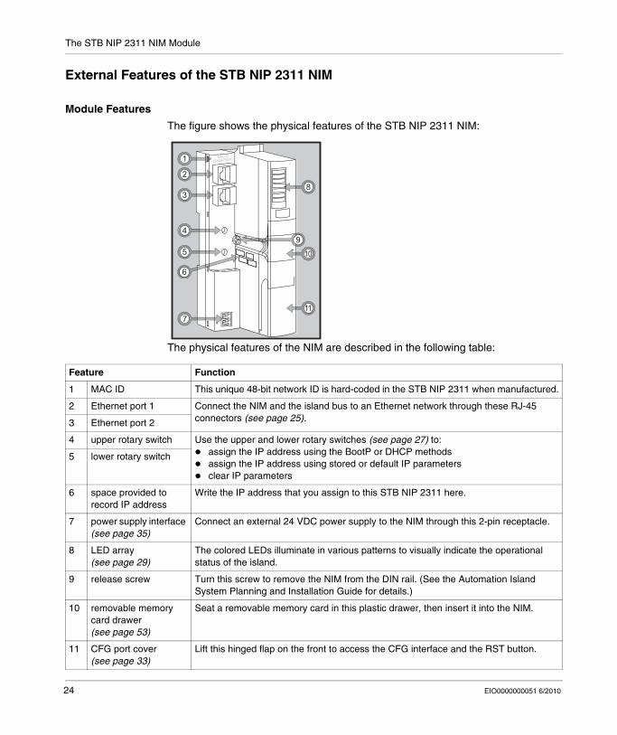
The figure shows the physical features of the STB NIP 2311 NIM:
The physical features of the NIM are described in the following table:
8
1
4
6
9
10
11
2
5
7
3
Feature Function
1 MAC ID This unique 48-bit network ID is hard-coded in the STB NIP 2311 when manufactured.
2 Ethernet port 1 Connect the NIM and the island bus to an Ethernet network through these RJ-45 connectors (see page 25).3 Ethernet port 2
4 upper rotary switch Use the upper and lower rotary switches (see page 27) to:assign the IP address using the BootP or DHCP methodsassign the IP address using stored or default IP parametersclear IP parameters
5 lower rotary switch
6 space provided to record IP address
Write the IP address that you assign to this STB NIP 2311 here.
7 power supply interface (see page 35)
Connect an external 24 VDC power supply to the NIM through this 2-pin receptacle.
8 LED array (see page 29)
The colored LEDs illuminate in various patterns to visually indicate the operational status of the island.
9 release screw Turn this screw to remove the NIM from the DIN rail. (See the Automation Island System Planning and Installation Guide for details.)
10 removable memory card drawer (see page 53)
Seat a removable memory card in this plastic drawer, then insert it into the NIM.
11 CFG port cover (see page 33)
Lift this hinged flap on the front to access the CFG interface and the RST button.
24 EIO0000000051 6/2010
The STB NIP 2311 NIM Module
STB NIP 2311 Ethernet Interfaces
Introduction
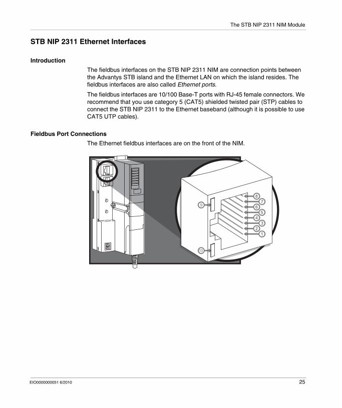
The fieldbus interfaces on the STB NIP 2311 NIM are connection points between the Advantys STB island and the Ethernet LAN on which the island resides. The fieldbus interfaces are also called Ethernet ports.
The fieldbus interfaces are 10/100 Base-T ports with RJ-45 female connectors. We recommend that you use category 5 (CAT5) shielded twisted pair (STP) cables to connect the STB NIP 2311 to the Ethernet baseband (although it is possible to use CAT5 UTP cables).
Fieldbus Port Connections
The Ethernet fieldbus interfaces are on the front of the NIM.
EIO0000000051 6/2010 25
The STB NIP 2311 NIM Module
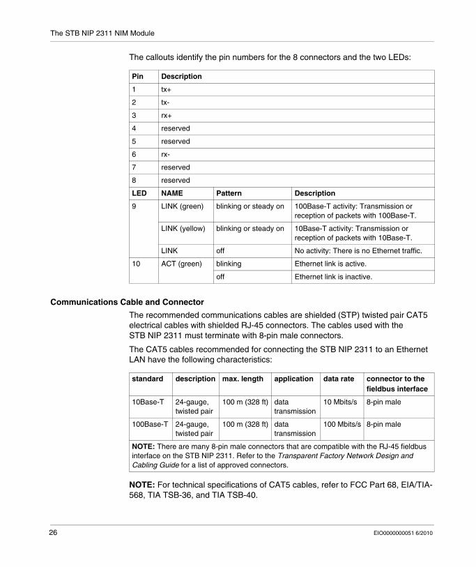
The callouts identify the pin numbers for the 8 connectors and the two LEDs:
Communications Cable and Connector
The recommended communications cables are shielded (STP) twisted pair CAT5 electrical cables with shielded RJ-45 connectors. The cables used with the STB NIP 2311 must terminate with 8-pin male connectors.
The CAT5 cables recommended for connecting the STB NIP 2311 to an Ethernet LAN have the following characteristics:
NOTE: For technical specifications of CAT5 cables, refer to FCC Part 68, EIA/TIA-568, TIA TSB-36, and TIA TSB-40.
Pin Description
1 tx+
2 tx-
3 rx+
4 reserved
5 reserved
6 rx-
7 reserved
8 reserved
LED NAME Pattern Description
9 LINK (green) blinking or steady on 100Base-T activity: Transmission or reception of packets with 100Base-T.
LINK (yellow) blinking or steady on 10Base-T activity: Transmission or reception of packets with 10Base-T.
LINK off No activity: There is no Ethernet traffic.
10 ACT (green) blinking Ethernet link is active.
off Ethernet link is inactive.
standard description max. length application data rate connector to the fieldbus interface
10Base-T 24-gauge, twisted pair
100 m (328 ft) data transmission
10 Mbits/s 8-pin male
100Base-T 24-gauge, twisted pair
100 m (328 ft) data transmission
100 Mbits/s 8-pin male
NOTE: There are many 8-pin male connectors that are compatible with the RJ-45 fieldbus interface on the STB NIP 2311. Refer to the Transparent Factory Network Design and Cabling Guide for a list of approved connectors.
26 EIO0000000051 6/2010
The STB NIP 2311 NIM Module
STB NIP 2311 Rotary Switches
Introduction
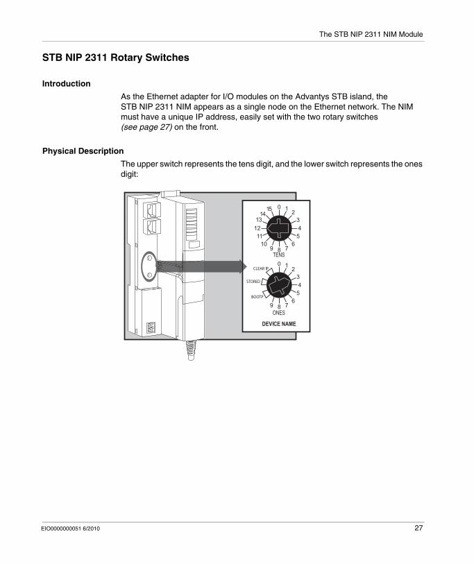
As the Ethernet adapter for I/O modules on the Advantys STB island, the STB NIP 2311 NIM appears as a single node on the Ethernet network. The NIM must have a unique IP address, easily set with the two rotary switches (see page 27) on the front.
Physical Description
The upper switch represents the tens digit, and the lower switch represents the ones digit:
EIO0000000051 6/2010 27
The STB NIP 2311 NIM Module
Switch Settings for IP Parameter Assignment
Valid rotary switch settings:For a switch-set device name, select a numeric value from 00 to 159. You can use both switches:
On the upper switch (tens digit), the available settings are 0 to 15.On the lower switch (ones digit), the available settings are 0 to 9.
The numeric setting is appended to the STB NIP 2311 part number. For example, an upper switch setting of 12 and a lower switch setting of 3 creates a device name of STBNIP2311_123, to which the DHCP server assigns an IP address.For a BootP-served IP address, select either of the two BOOTP positions on the bottom switch.Set the lower switch to one of its two STORED positions to get either:
a fixed IP address: A fixed address is assigned in the STB NIP 2311 embedded web pages (see page 143) or the Advantys configuration software.a MAC-based IP address: A MAC-based address is used when the STB NIP 2311 is direct from the factory and no IP address has been assigned with the module’s embedded web pages.
The two CLEAR IP settings clear the NIM's internal IP parameters, including the internal device name. (In this case the island does not have an IP address.)
NOTE:
Refer to the detailed descriptions of methods for IP addressing (see page 73).To see how the STB NIP 2311 prioritizes addressing options, refer to the IP parameterization flowchart (see page 76).The STB NIP 2311 requires a valid IP address to communicate on the Ethernet network and with a host. You must power cycle the STB NIP 2311 to configure it with the IP address set with the rotary switches. (You can also configure an IP address that is used after power up using the IP configuration web page (see page 150).)
28 EIO0000000051 6/2010
The STB NIP 2311 NIM Module
STB NIP 2311 LED Indicators
Introduction
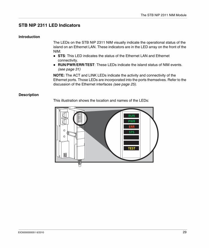
The LEDs on the STB NIP 2311 NIM visually indicate the operational status of the island on an Ethernet LAN. These indicators are in the LED array on the front of the NIM:
STS: This LED indicates the status of the Ethernet LAN and Ethernet connectivity.RUN/PWR/ERR/TEST: These LEDs indicate the island status of NIM events. (see page 31)
NOTE: The ACT and LINK LEDs indicate the activity and connectivity of the Ethernet ports. Those LEDs are incorporated into the ports themselves. Refer to the discussion of the Ethernet interfaces (see page 25).
Description
This illustration shows the location and names of the LEDs:
RUN
PWR
ERR
STS
TEST
EIO0000000051 6/2010 29
The STB NIP 2311 NIM Module
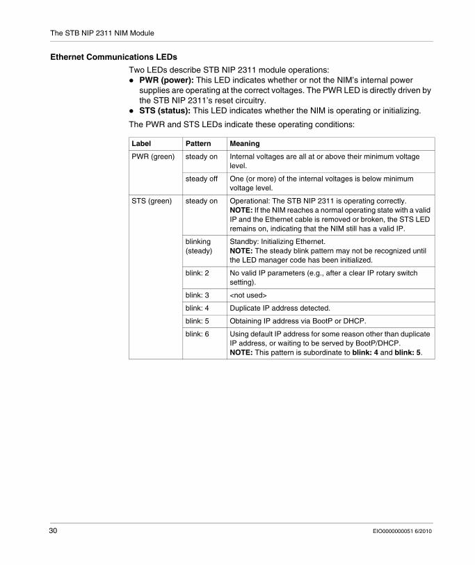
Ethernet Communications LEDs
Two LEDs describe STB NIP 2311 module operations:PWR (power): This LED indicates whether or not the NIM’s internal power supplies are operating at the correct voltages. The PWR LED is directly driven by the STB NIP 2311’s reset circuitry.STS (status): This LED indicates whether the NIM is operating or initializing.
The PWR and STS LEDs indicate these operating conditions:
Label Pattern Meaning
PWR (green) steady on Internal voltages are all at or above their minimum voltage level.
steady off One (or more) of the internal voltages is below minimum voltage level.
STS (green) steady on Operational: The STB NIP 2311 is operating correctly.NOTE: If the NIM reaches a normal operating state with a valid IP and the Ethernet cable is removed or broken, the STS LED remains on, indicating that the NIM still has a valid IP.
blinking (steady)
Standby: Initializing Ethernet.NOTE: The steady blink pattern may not be recognized until the LED manager code has been initialized.
blink: 2 No valid IP parameters (e.g., after a clear IP rotary switch setting).
blink: 3 <not used>
blink: 4 Duplicate IP address detected.
blink: 5 Obtaining IP address via BootP or DHCP.
blink: 6 Using default IP address for some reason other than duplicate IP address, or waiting to be served by BootP/DHCP.NOTE: This pattern is subordinate to blink: 4 and blink: 5.
30 EIO0000000051 6/2010

The STB NIP 2311 NIM Module
Advantys STB Island Status LEDs
About the Island Status LEDs
The following table describes:the island bus condition(s) communicated by the LEDsthe colors and blink patterns used to indicate each condition
As you refer to the table, keep in mind the following:It is assumed that the PWR LED is on continuously, indicating that the NIM is receiving adequate power. If the PWR LED is off, logic power (see page 36) to the NIM is off or insufficient.Individual blinks are approximately 200 ms. There is a 1-second interval between blink sequences. Please note:
blinking: blinks steadily, alternating between 200 ms on and 200 ms off.blink 1: blinks once (200 ms), then 1 second off.blink 2: blinks twice (200 ms on, 200 ms off, 200 ms on), then 1 second off.blink N: blinks N (some number of) times, then 1 second off.If the TEST LED is on, either the Advantys configuration software or an HMI panel is the master of the island bus. If the TEST LED is off, the fieldbus master has control of the island bus.
EIO0000000051 6/2010 31

The STB NIP 2311 NIM Module
Island Status LED Indicators
RUN (green) ERR (red) TEST (yellow) Meaningblink: 2 blink: 2 blink: 2 The island is powering up (self test in progress).off off off The island is initializing. The island is not started.blink: 1 off off The island has been put in the pre-operational state by the RST button.
The island is not started.blink: 3 The NIM is reading from the removable memory card (see page 56).on The NIM is overwriting its Flash memory with the card’s configuration
data. (See note 1.)off blink: 8 off The contents of the removable memory card are invalid.blinking (steady)
off off The NIM is configuring (see page 43) or auto-configuring (see page 48) the island bus. The island bus is not started.
blinking off on Auto-configuration data is being written to Flash memory. (See note 1.)blink: 3 blink: 2 off Configuration mismatch detected after power up. At least one mandatory
module does not match. The island bus is not started.off blink: 2 off The NIM has detected a module assignment error; the island bus is not
started.blink: 5 invalid internal triggering protocol
off blink: 6 off The NIM detects no I/O modules on the island bus.blinking (steady)
off The NIM detects no I/O modules on the island bus ... or ...No further communications with the NIM are possible. Probable causes:
internal condition
wrong module ID
device did not auto-address (see page 44)
mandatory module is incorrectly configured (see page 227)
process image is not valid
device is incorrectly configured (see page 48)
The NIM has detected an anomaly on the island bus.
receive/transmit queue software overrunon off off The island bus is operational.on blink 3 off At least one standard module does not match. The island bus is
operational with a configuration mismatch.on blink: 2 off There is a serious configuration mismatch (when a module is pulled from
a running island). The island bus is now in pre-operational mode because of one or more mismatched mandatory modules.
blink: 4 off off The island bus is stopped (when a module is pulled from a running island). No further communications with the island are possible.
off on off Internal condition: The NIM is inoperable.[any] [any] on Test mode is enabled: The configuration software or an HMI panel can
set outputs. (See note 2.)1 The TEST LED is on temporarily during the Flash overwrite process.
2 The TEST LED is on steadily while the device connected to the CFG port is in control.
32 EIO0000000051 6/2010
The STB NIP 2311 NIM Module
The CFG Interface
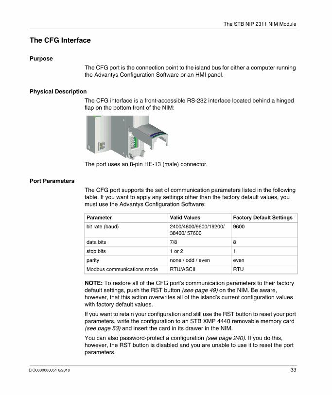
Purpose
The CFG port is the connection point to the island bus for either a computer running the Advantys Configuration Software or an HMI panel.
Physical Description
The CFG interface is a front-accessible RS-232 interface located behind a hinged flap on the bottom front of the NIM:
The port uses an 8-pin HE-13 (male) connector.
Port Parameters
The CFG port supports the set of communication parameters listed in the following table. If you want to apply any settings other than the factory default values, you must use the Advantys Configuration Software:
NOTE: To restore all of the CFG port’s communication parameters to their factory default settings, push the RST button (see page 49) on the NIM. Be aware, however, that this action overwrites all of the island’s current configuration values with factory default values.
If you want to retain your configuration and still use the RST button to reset your port parameters, write the configuration to an STB XMP 4440 removable memory card (see page 53) and insert the card in its drawer in the NIM.
You can also password-protect a configuration (see page 240). If you do this, however, the RST button is disabled and you are unable to use it to reset the port parameters.
Parameter Valid Values Factory Default Settings
bit rate (baud) 2400/4800/9600/19200/ 38400/ 57600
9600
data bits 7/8 8
stop bits 1 or 2 1
parity none / odd / even even
Modbus communications mode RTU/ASCII RTU
EIO0000000051 6/2010 33
The STB NIP 2311 NIM Module
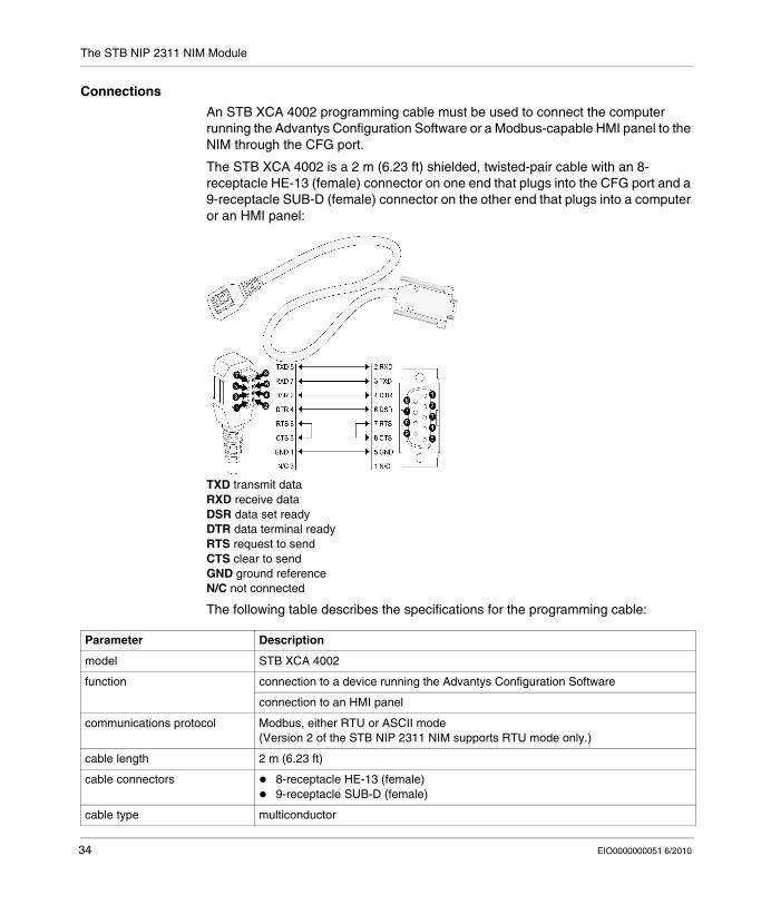
Connections
An STB XCA 4002 programming cable must be used to connect the computer running the Advantys Configuration Software or a Modbus-capable HMI panel to the NIM through the CFG port.
The STB XCA 4002 is a 2 m (6.23 ft) shielded, twisted-pair cable with an 8-receptacle HE-13 (female) connector on one end that plugs into the CFG port and a 9-receptacle SUB-D (female) connector on the other end that plugs into a computer or an HMI panel:
TXD transmit dataRXD receive dataDSR data set readyDTR data terminal readyRTS request to sendCTS clear to sendGND ground referenceN/C not connected
The following table describes the specifications for the programming cable:
Parameter Description
model STB XCA 4002
function connection to a device running the Advantys Configuration Software
connection to an HMI panel
communications protocol Modbus, either RTU or ASCII mode (Version 2 of the STB NIP 2311 NIM supports RTU mode only.)
cable length 2 m (6.23 ft)
cable connectors 8-receptacle HE-13 (female)9-receptacle SUB-D (female)
cable type multiconductor
34 EIO0000000051 6/2010

The STB NIP 2311 NIM Module
The Power Supply Interface
Physical Description
The built-in power supply on the STB NIP 2311 NIM requires 24 VDC from an external SELV-rated power source. The connection between the 24 VDC source and the island is a 2-pinmale connector:
1 connector 1: 24 VDC2 connector 2: common
Connectors
Screw-type and spring-type power connectors are provided with the NIM. (Replacement connectors are also available.) The figure shows each connector type:
1 STB XTS 1120 screw-type power connector (front and back)2 STB XTS 2120 spring clamp power connector (front and back)3 wire entry slot4 screw clamp access5 spring clamp actuation button
Each entry slot accepts a wire in the range 28 to 16 AWG (0.14 to 1.5 mm2).
EIO0000000051 6/2010 35

The STB NIP 2311 NIM Module
Logic Power
Introduction
Logic power is a 5 VDC power signal on the island bus that the I/O modules require for internal processing. The NIM has a built-in power supply that provides logic power. The NIM sends the 5 V logic power signal across the island bus to support the modules in the primary segment.
External Source Power
Input from an external 24 VDC power supply (see page 38) is needed as the source power for the NIM’s built-in power supply. The NIM’s built-in power supply converts the incoming 24 V to 5 V of logic power. The external supply must be rated safety extra low voltage (SELV-rated).
CAUTIONIMPROPER GALVANIC ISOLATION
The power components are not galvanically isolated. They are intended for use only in systems designed to provide SELV isolation between the supply inputs or outputs and the load devices or system power bus. You must use SELV-rated supplies to provide 24 VDC source power to the NIM.
Failure to follow these instructions can result in injury or equipment damage.
36 EIO0000000051 6/2010
The STB NIP 2311 NIM Module
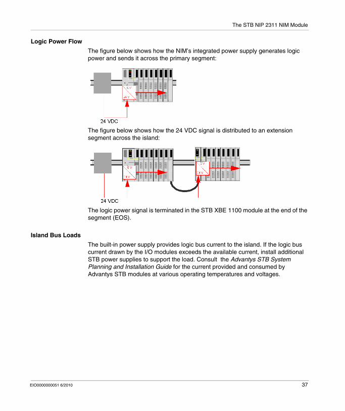
Logic Power Flow
The figure below shows how the NIM’s integrated power supply generates logic power and sends it across the primary segment:
The figure below shows how the 24 VDC signal is distributed to an extension segment across the island:
The logic power signal is terminated in the STB XBE 1100 module at the end of the segment (EOS).
Island Bus Loads
The built-in power supply provides logic bus current to the island. If the logic bus current drawn by the I/O modules exceeds the available current, install additional STB power supplies to support the load. Consult the Advantys STB System Planning and Installation Guide for the current provided and consumed by Advantys STB modules at various operating temperatures and voltages.
EIO0000000051 6/2010 37

The STB NIP 2311 NIM Module
Selecting a Source Power Supply for the Island’s Logic Power Bus
Logic Power Requirements
An external 24 VDC power supply is needed as the source for logic power to the island bus. The external power supply connects to the island’s NIM. This external supply provides the 24 V input to the built-in 5 V power supply in the NIM.
The NIM delivers the logic power signal to the primary segment only. Special STB XBE 1300 beginning-of-segment (BOS) modules, located in the first slot of each extension segment, have their own built-in power supplies, which provide logic power to the STB I/O modules in the extension segments. Each BOS module that you install requires 24 VDC from an external power supply.
Characteristics of the External Power Supply
The external power supply needs to deliver 24 VDC source power to the island. The supply that you select can have a low range limit of 19.2 VDC and a high range limit of 30 VDC. The external supply must be rated safety extra low voltage (SELV-rated).
The SELV rating means that, in addition to basic insulation between hazardous voltages and the DC output, a second supplementary insulation layer has been added. As a result, if a single component/insulation does not perform, the DC output does not exceed SELV limits.
Calculating the Wattage Requirement
The amount of power (see page 37) that the external power supply must deliver is a function of the number of modules and the number of built-in power supplies installed on the island.
The external supply needs to provide 13 W of power for the NIM and 13 W for each additional STB power supply (like an STB XBE 1300 BOS module). For example, a system with one NIM in the primary segment and one BOS module in an extension segment would require 26 W of power.
CAUTIONIMPROPER GALVANIC ISOLATION
The power components are not galvanically isolated. They are intended for use only in systems designed to provide SELV isolation between the supply inputs or outputs and the load devices or system power bus. You must use SELV-rated supplies to provide 24 VDC source power to the NIM.
Failure to follow these instructions can result in injury or equipment damage.
38 EIO0000000051 6/2010
The STB NIP 2311 NIM Module
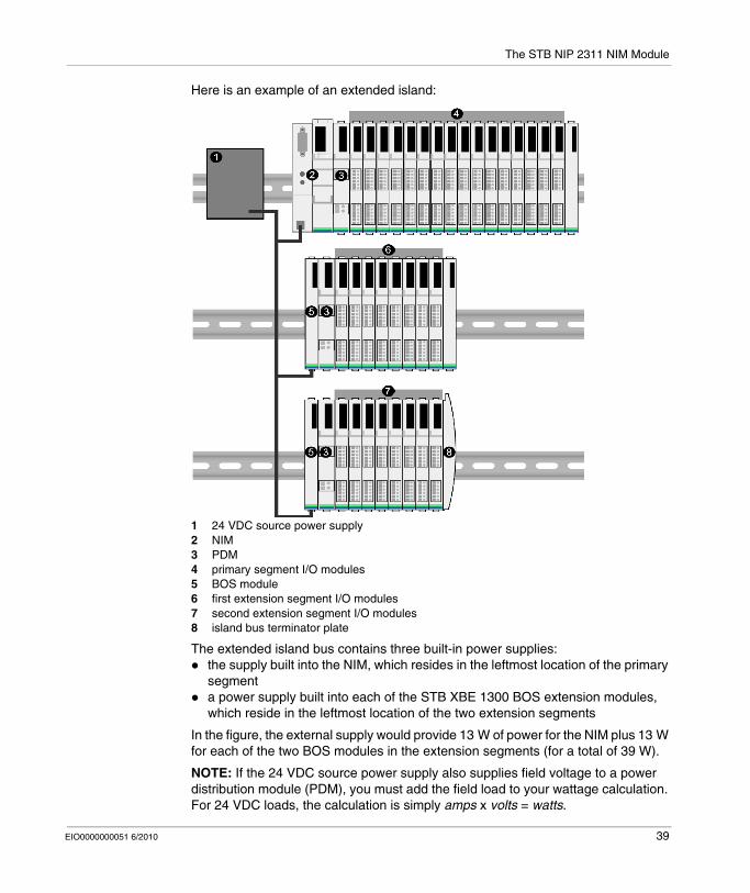
Here is an example of an extended island:
1 24 VDC source power supply2 NIM3 PDM4 primary segment I/O modules5 BOS module6 first extension segment I/O modules7 second extension segment I/O modules8 island bus terminator plate
The extended island bus contains three built-in power supplies:the supply built into the NIM, which resides in the leftmost location of the primary segmenta power supply built into each of the STB XBE 1300 BOS extension modules, which reside in the leftmost location of the two extension segments
In the figure, the external supply would provide 13 W of power for the NIM plus 13 W for each of the two BOS modules in the extension segments (for a total of 39 W).
NOTE: If the 24 VDC source power supply also supplies field voltage to a power distribution module (PDM), you must add the field load to your wattage calculation. For 24 VDC loads, the calculation is simply amps x volts = watts.
EIO0000000051 6/2010 39

The STB NIP 2311 NIM Module
Suggested Devices
The external power supply is generally enclosed in the same cabinet as the island. Usually the external power supply is a DIN rail-mountable unit.
We recommend using ABL8 Phaseo power supplies.
40 EIO0000000051 6/2010
The STB NIP 2311 NIM Module
STB NIP 2311 Module Specifications
Specifications Detail
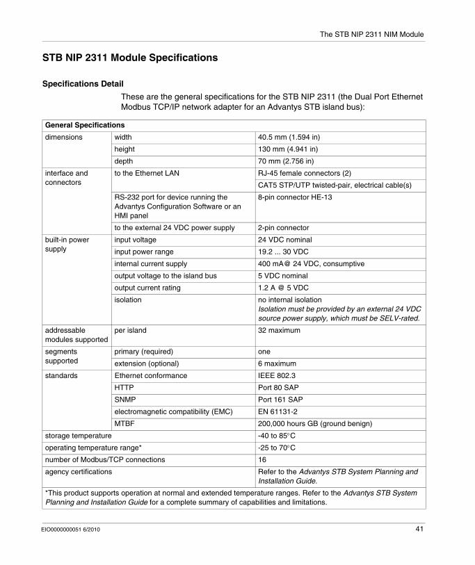
These are the general specifications for the STB NIP 2311 (the Dual Port Ethernet Modbus TCP/IP network adapter for an Advantys STB island bus):
General Specifications
dimensions width 40.5 mm (1.594 in)
height 130 mm (4.941 in)
depth 70 mm (2.756 in)
interface and connectors
to the Ethernet LAN RJ-45 female connectors (2)
CAT5 STP/UTP twisted-pair, electrical cable(s)
RS-232 port for device running the Advantys Configuration Software or an HMI panel
8-pin connector HE-13
to the external 24 VDC power supply 2-pin connector
built-in power supply
input voltage 24 VDC nominal
input power range 19.2 ... 30 VDC
internal current supply 400 mA@ 24 VDC, consumptive
output voltage to the island bus 5 VDC nominal
output current rating 1.2 A @ 5 VDC
isolation no internal isolationIsolation must be provided by an external 24 VDC source power supply, which must be SELV-rated.
addressable modules supported
per island 32 maximum
segments supported
primary (required) one
extension (optional) 6 maximum
standards Ethernet conformance IEEE 802.3
HTTP Port 80 SAP
SNMP Port 161 SAP
electromagnetic compatibility (EMC) EN 61131-2
MTBF 200,000 hours GB (ground benign)
storage temperature -40 to 85°C
operating temperature range* -25 to 70°C
number of Modbus/TCP connections 16
agency certifications Refer to the Advantys STB System Planning and Installation Guide.
*This product supports operation at normal and extended temperature ranges. Refer to the Advantys STB System Planning and Installation Guide for a complete summary of capabilities and limitations.
EIO0000000051 6/2010 41

The STB NIP 2311 NIM Module
42 EIO0000000051 6/2010
EIO0000000051 6/2010
3
How to Configure the Island
EIO0000000051 6/2010
How to Configure the Island
Introduction
The information in this chapter describes the auto-addressing and auto-configuration processes. An Advantys STB system has an auto-configuration capability in which the actual configuration of I/O modules on the island is read and saved to Flash.
The removable memory card is discussed in this chapter. The card is an Advantys STB option for storing configuration data offline. Factory default settings can be restored to the island bus I/O modules and the CFG port by engaging the RST button.
The NIM is the physical and logical location of all island bus configuration data and functionality.
What's in this Chapter?
This chapter contains the following sections:
Section Topic Page
3.1 Understanding Island Bus Addresses 44
3.2 Autoconfiguring Island Parameters 47
3.3 Using a Removable Memory Card to Configure the Island 52
3.4 Configuring the STB NIP 2311 NIM with the Advantys Configuration Software
59
43
How to Configure the Island
3.1 Understanding Island Bus Addresses
How Do Modules Automatically Get Island Bus Addresses?
Introduction
Each time that the island is powered up or reset, the NIM automatically assigns a unique island bus address to each module on the island that engages in data exchange. All Advantys STB I/O modules and preferred devices engage in data exchange and require island bus addresses.
About the Island Bus Address
An island bus address is a unique integer value in the range 1 through 127 that identifies the physical location of each addressable module on the island. The NIM's address is always 127. Addresses 1 through 32 are available for I/O modules and other island devices.
During initialization, the NIM detects the order in which modules are installed and addresses them sequentially from left to right, starting with the first addressable module after the NIM. No user action is required to address these modules.
Addressable Modules
Advantys STB I/O modules and preferred devices are auto-addressable. Enhanced CANopen modules are not auto-addressable. They require manual address settings.
Because they do not exchange data on the island bus, the following are not addressed:
bus extension modulesPDMs such as the STB PDT 3100 and STB PDT 2100auxiliary power supplies, such as the STB CPS 2111termination plate
44 EIO0000000051 6/2010
How to Configure the Island
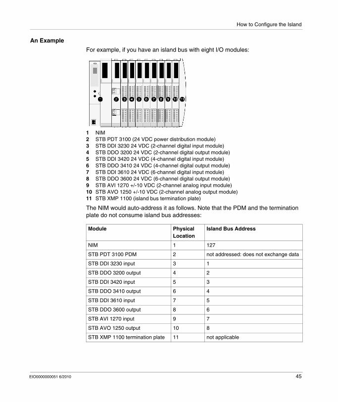
An Example
For example, if you have an island bus with eight I/O modules:
1 NIM2 STB PDT 3100 (24 VDC power distribution module)3 STB DDI 3230 24 VDC (2-channel digital input module)4 STB DDO 3200 24 VDC (2-channel digital output module)5 STB DDI 3420 24 VDC (4-channel digital input module)6 STB DDO 3410 24 VDC (4-channel digital output module)7 STB DDI 3610 24 VDC (6-channel digital input module)8 STB DDO 3600 24 VDC (6-channel digital output module)9 STB AVI 1270 +/-10 VDC (2-channel analog input module)10 STB AVO 1250 +/-10 VDC (2-channel analog output module)11 STB XMP 1100 (island bus termination plate)
The NIM would auto-address it as follows. Note that the PDM and the termination plate do not consume island bus addresses:
Module Physical Location
Island Bus Address
NIM 1 127
STB PDT 3100 PDM 2 not addressed: does not exchange data
STB DDI 3230 input 3 1
STB DDO 3200 output 4 2
STB DDI 3420 input 5 3
STB DDO 3410 output 6 4
STB DDI 3610 input 7 5
STB DDO 3600 output 8 6
STB AVI 1270 input 9 7
STB AVO 1250 output 10 8
STB XMP 1100 termination plate 11 not applicable
EIO0000000051 6/2010 45

How to Configure the Island
Associating the Module Type with the Island Bus Location
As a result of the configuration process, the NIM automatically identifies physical locations on the island bus with specific I/O module types. This feature enables you to hot swap a non-operational module with a new module of the same type.
46 EIO0000000051 6/2010

How to Configure the Island
3.2 Autoconfiguring Island Parameters
Overview
This section shows you how to use the RST button to autoconfigure the modules on an Advantys island by restoring their default parameter settings.
What's in this Section?
This section contains the following topics:
Topic Page
How to Auto-Configure Default Parameters for Island Modules 48
What is the RST Button? 49
How to Overwrite Flash Memory with the RST Button 50
EIO0000000051 6/2010 47
How to Configure the Island
How to Auto-Configure Default Parameters for Island Modules
Introduction
All Advantys STB I/O modules are shipped with a set of predefined parameters that allow an island to be operational as soon as it is initialized. This ability of island modules to operate with default parameters is known as auto-configuration. Once an island bus has been installed, assembled, and successfully parameterized and configured for your fieldbus network, you can begin using it as a node on that network.
NOTE: A valid island configuration does not require the intervention of the optional Advantys Configuration Software.
About Auto-Configuration
Auto-configuration occurs under these circumstances:The island is powered up with a factory default NIM configuration. (If this NIM is subsequently used to create a new island, auto-configuration does not occur when that new island is powered.)You push the RST button (see page 49).You force an auto-configuration using the Advantys Configuration Software.
As part of the auto-configuration process, the NIM checks each module and confirms that it has been properly connected to the island bus. The NIM stores the default operating parameters for each module in Flash memory.
Customizing a Configuration
In a custom configuration, you can:customize the operating parameters of I/O modulescreate reflex actions (see page 230)add enhanced CANopen standard devices to the island buscustomize other island capabilitiesconfigure communication parameters (STB NIP 2311 only)
48 EIO0000000051 6/2010
How to Configure the Island
What is the RST Button?
Summary
The RST function is basically a Flash memory overwriting operation. This means that RST is functional only after the island has been successfully configured at least once. All RST functionality is performed with the RST button, which is enabled only in edit mode (see page 56).
Physical Description
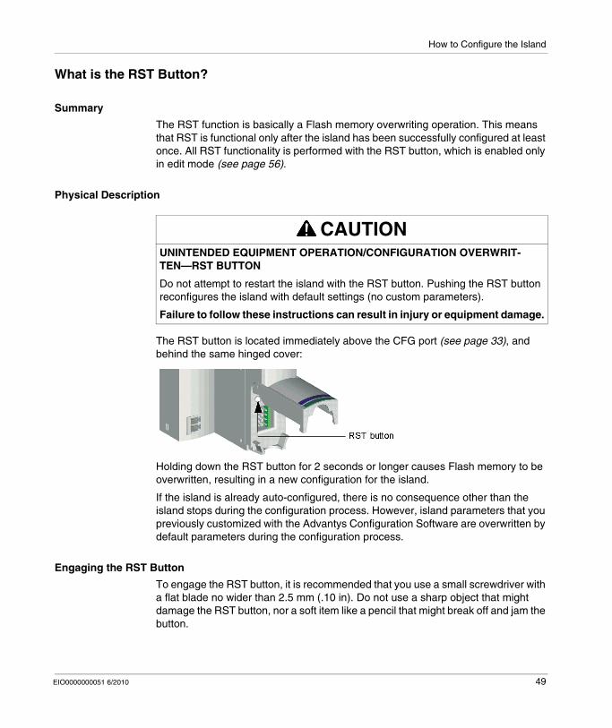
The RST button is located immediately above the CFG port (see page 33), and behind the same hinged cover:
Holding down the RST button for 2 seconds or longer causes Flash memory to be overwritten, resulting in a new configuration for the island.
If the island is already auto-configured, there is no consequence other than the island stops during the configuration process. However, island parameters that you previously customized with the Advantys Configuration Software are overwritten by default parameters during the configuration process.
Engaging the RST Button
To engage the RST button, it is recommended that you use a small screwdriver with a flat blade no wider than 2.5 mm (.10 in). Do not use a sharp object that might damage the RST button, nor a soft item like a pencil that might break off and jam the button.
CAUTIONUNINTENDED EQUIPMENT OPERATION/CONFIGURATION OVERWRIT-TEN—RST BUTTON
Do not attempt to restart the island with the RST button. Pushing the RST button reconfigures the island with default settings (no custom parameters).
Failure to follow these instructions can result in injury or equipment damage.
EIO0000000051 6/2010 49
How to Configure the Island
How to Overwrite Flash Memory with the RST Button
Introduction
Pushing the RST button (see page 49) causes the island bus to reconfigure itself with factory default operating parameters.
The RST function allows you to reconfigure the operating parameters and values of an island by overwriting the current configuration in Flash memory. RST functionality affects the configuration values associated with the I/O modules on the island, the operational mode of the island, and the CFG port parameters.
The RST function is performed by holding down the RST button (see page 49) for at least two seconds. The RST button is enabled only in edit mode. In protected mode (see page 240), the RST button is disabled; pressing it has no effect.
NOTE: Pressing the RST button does not affect network settings. (In this case, the STB NIP 2311 NIM keeps its IP parameters.)
RST Configuration Scenarios
The following scenarios describe some of the ways that you can use the RST function to configure your island:
Restore factory-default parameters and values to an island, including to the I/O modules and the CFG port (see page 33).Add a new I/O module to a previously auto-configured (see page 48) island.If a new I/O module is added to the island, pressing the RST button forces the auto-configuration process. The updated island configuration data is automatically written to Flash memory.
CAUTIONUNINTENDED EQUIPMENT OPERATION/CONFIGURATION DATA OVER-WRITTEN—RST BUTTON
Do not attempt to restart the island by pushing the RST button.
Failure to follow these instructions can result in injury or equipment damage.
50 EIO0000000051 6/2010
How to Configure the Island
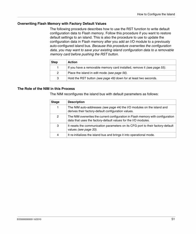
Overwriting Flash Memory with Factory Default Values
The following procedure describes how to use the RST function to write default configuration data to Flash memory. Follow this procedure if you want to restore default settings to an island. This is also the procedure to use to update the configuration data in Flash memory after you add an I/O module to a previously auto-configured island bus. Because this procedure overwrites the configuration data, you may want to save your existing island configuration data to a removable memory card before pushing the RST button.
The Role of the NIM in this Process
The NIM reconfigures the island bus with default parameters as follows:
Step Action
1 If you have a removable memory card installed, remove it (see page 55).
2 Place the island in edit mode (see page 56).
3 Hold the RST button (see page 49) down for at least two seconds.
Stage Description
1 The NIM auto-addresses (see page 44) the I/O modules on the island and derives their factory-default configuration values.
2 The NIM overwrites the current configuration in Flash memory with configuration data that uses the factory-default values for the I/O modules.
3 It resets the communication parameters on its CFG port to their factory-default values (see page 33).
4 It re-initializes the island bus and brings it into operational mode.
EIO0000000051 6/2010 51

How to Configure the Island
3.3 Using a Removable Memory Card to Configure the Island
Overview
This section describes removable memory card usage.
What's in this Section?
This section contains the following topics:
Topic Page
How to Install the STB XMP 4440 Optional Removable Memory Card 53
Using the STB XMP 4440 Optional Removable Memory Card to Configure the Island
56
52 EIO0000000051 6/2010

How to Configure the Island
How to Install the STB XMP 4440 Optional Removable Memory Card
Introduction
The card’s performance can be degraded by dirt or grease on its circuitry. Contamination or damage may create an invalid configuration.
The STB XMP 4440 removable memory card is a 32-kbyte subscriber identification module (SIM) that lets you store (see page 236), distribute, and reuse custom island bus configurations. If the island is in edit mode and a removable memory card containing a valid island bus configuration is inserted in the NIM, the configuration data on the card overwrites the configuration data in Flash memory, and is adopted when the island starts up. When the island is in protected mode, it ignores the presence of a removable memory card. (Only users with the STB NIP 2311 NIM can save configuration data to the removable memory card. With that NIM, valid configuration data on the card overwrites the data in flash memory, even in protected mode.)
The removable memory card is an optional Advantys STB feature.
Remember:Keep the card free of contaminants and dirt.Network configuration data, such as the fieldbus baud setting, cannot be saved to the card. (The exception is the STB NIP 2311 NIM.)
CAUTIONLOSS OF CONFIGURATION: MEMORY CARD DAMAGE OR CONTAMINA-TION
Use care when handling the card.Inspect for contamination, physical damage, and scratches before installing the card in the NIM drawer.If the card does get dirty, clean it with a soft dry cloth.
Failure to follow these instructions can result in injury or equipment damage.
EIO0000000051 6/2010 53

How to Configure the Island
Installing the Card
Use the following procedure to install the memory card:
Step Action
1 Punch out the removable memory card from the plastic card on which it is shipped.
Make sure that the edges of the card are smooth after you punch it out.
2 Open the card drawer on the front of the NIM. If it makes it easier for you to work, you may pull the drawer completely out from the NIM housing.
3 Align the chamfered edge (the 45° corner) of the removable memory card with the one in the mounting slot in the card drawer. Hold the card so that the chamfer is in the upper left corner.
4 Seat the card in the mounting slot, applying slight pressure to the card until it snaps into place. The back edge of the card must be flush with the back of the drawer.
5 Close the drawer.
54 EIO0000000051 6/2010
How to Configure the Island
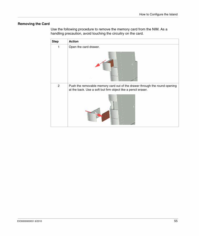
Removing the Card
Use the following procedure to remove the memory card from the NIM. As a handling precaution, avoid touching the circuitry on the card.
Step Action
1 Open the card drawer.
2 Push the removable memory card out of the drawer through the round opening at the back. Use a soft but firm object like a pencil eraser.
EIO0000000051 6/2010 55
How to Configure the Island
Using the STB XMP 4440 Optional Removable Memory Card to Configure the Island
Introduction
A removable memory card is read when an island is powered on or during a reset operation. If the configuration data on the card is valid, the current configuration data in Flash memory is overwritten.
A removable memory card can be active only if an island is in edit mode. If an island is in protected mode (see page 240), the card and its data are ignored. (Only users with the STB NIP 2311 NIM can save configuration data to the removable memory card. With that NIM, valid configuration data on the card overwrites the data in flash memory, even in protected mode.)
Configuration Scenarios
The following discussion describes several island configuration scenarios that use the removable memory card. (The scenarios assume that a removable memory card is already installed in the NIM.):
initial island bus configurationreplace the current configuration data in Flash memory in order to:
apply custom configuration data to your islandtemporarily implement an alternative configuration; for example, to replace an island configuration used daily with one used to fulfill a special order
copying configuration data from one NIM to another, including from a non-operational NIM to its replacement; the NIMs must have the same part numberconfiguring multiple islands with the same configuration data
NOTE: Whereas writing configuration data from the removable memory card to the NIM does not require use of the optional Advantys Configuration Software, you must use this software to save (write) configuration data to the removable memory card in the first place.
Edit Mode
Your island bus must be in edit mode to be configured. In edit mode, the island bus can be written to as well as monitored.
Edit mode is the default operational mode for the Advantys STB island:A new island is in edit mode.Edit mode is the default mode for a configuration downloaded from the Advantys Configuration Software to the configuration memory area in the NIM.
56 EIO0000000051 6/2010
How to Configure the Island
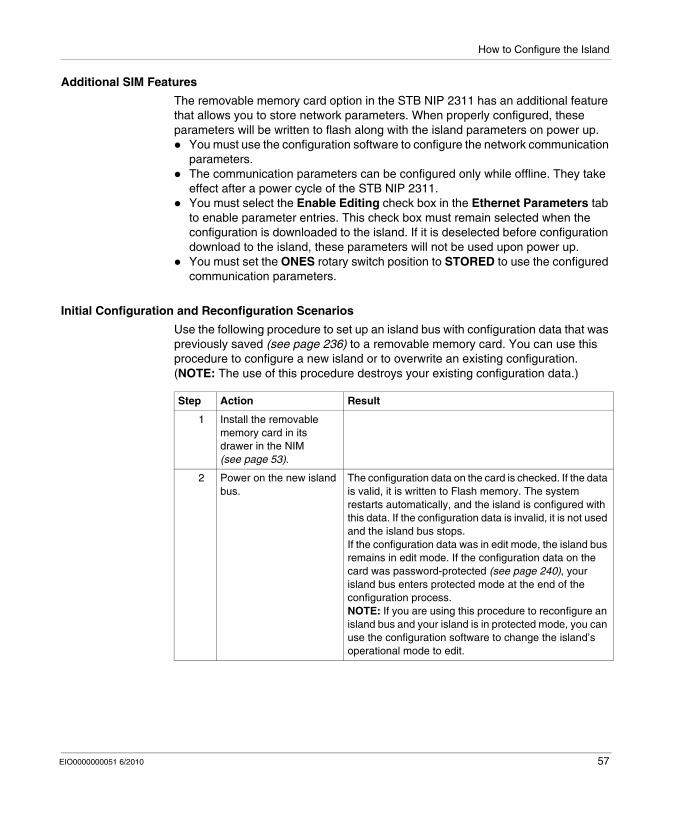
Additional SIM Features
The removable memory card option in the STB NIP 2311 has an additional feature that allows you to store network parameters. When properly configured, these parameters will be written to flash along with the island parameters on power up.
You must use the configuration software to configure the network communication parameters.The communication parameters can be configured only while offline. They take effect after a power cycle of the STB NIP 2311.You must select the Enable Editing check box in the Ethernet Parameters tab to enable parameter entries. This check box must remain selected when the configuration is downloaded to the island. If it is deselected before configuration download to the island, these parameters will not be used upon power up.You must set the ONES rotary switch position to STORED to use the configured communication parameters.
Initial Configuration and Reconfiguration Scenarios
Use the following procedure to set up an island bus with configuration data that was previously saved (see page 236) to a removable memory card. You can use this procedure to configure a new island or to overwrite an existing configuration. (NOTE: The use of this procedure destroys your existing configuration data.)
Step Action Result
1 Install the removable memory card in its drawer in the NIM (see page 53).
2 Power on the new island bus.
The configuration data on the card is checked. If the data is valid, it is written to Flash memory. The system restarts automatically, and the island is configured with this data. If the configuration data is invalid, it is not used and the island bus stops.If the configuration data was in edit mode, the island bus remains in edit mode. If the configuration data on the card was password-protected (see page 240), your island bus enters protected mode at the end of the configuration process.NOTE: If you are using this procedure to reconfigure an island bus and your island is in protected mode, you can use the configuration software to change the island’s operational mode to edit.
EIO0000000051 6/2010 57
How to Configure the Island
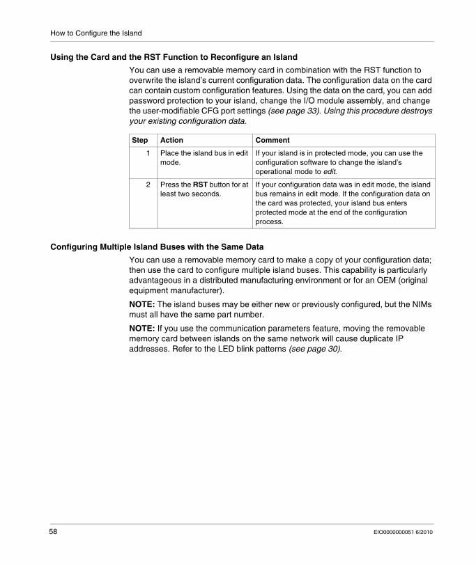
Using the Card and the RST Function to Reconfigure an Island
You can use a removable memory card in combination with the RST function to overwrite the island’s current configuration data. The configuration data on the card can contain custom configuration features. Using the data on the card, you can add password protection to your island, change the I/O module assembly, and change the user-modifiable CFG port settings (see page 33). Using this procedure destroys your existing configuration data.
Configuring Multiple Island Buses with the Same Data
You can use a removable memory card to make a copy of your configuration data; then use the card to configure multiple island buses. This capability is particularly advantageous in a distributed manufacturing environment or for an OEM (original equipment manufacturer).
NOTE: The island buses may be either new or previously configured, but the NIMs must all have the same part number.
NOTE: If you use the communication parameters feature, moving the removable memory card between islands on the same network will cause duplicate IP addresses. Refer to the LED blink patterns (see page 30).
Step Action Comment
1 Place the island bus in edit mode.
If your island is in protected mode, you can use the configuration software to change the island’s operational mode to edit.
2 Press the RST button for at least two seconds.
If your configuration data was in edit mode, the island bus remains in edit mode. If the configuration data on the card was protected, your island bus enters protected mode at the end of the configuration process.
58 EIO0000000051 6/2010
How to Configure the Island
3.4 Configuring the STB NIP 2311 NIM with the Advantys Configuration Software
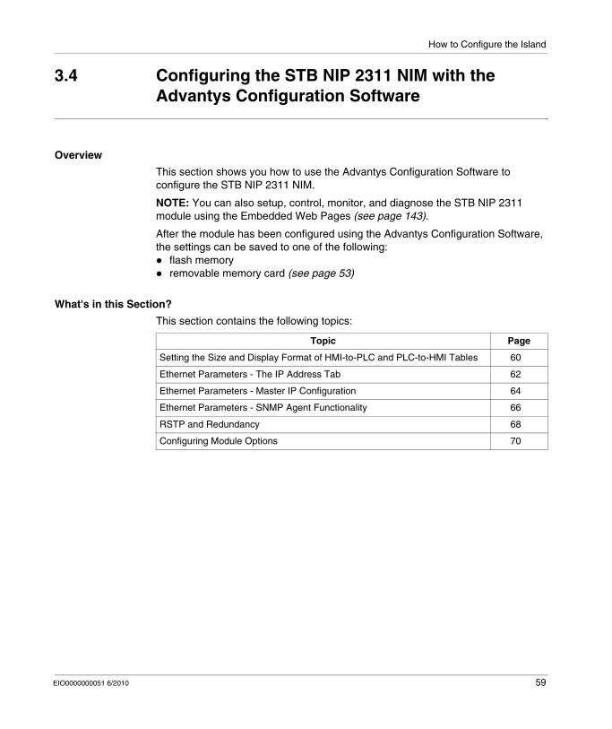
Overview
This section shows you how to use the Advantys Configuration Software to configure the STB NIP 2311 NIM.
NOTE: You can also setup, control, monitor, and diagnose the STB NIP 2311 module using the Embedded Web Pages (see page 143).
After the module has been configured using the Advantys Configuration Software, the settings can be saved to one of the following:
flash memoryremovable memory card (see page 53)
What's in this Section?
This section contains the following topics:
Topic Page
Setting the Size and Display Format of HMI-to-PLC and PLC-to-HMI Tables 60
Ethernet Parameters - The IP Address Tab 62
Ethernet Parameters - Master IP Configuration 64
Ethernet Parameters - SNMP Agent Functionality 66
RSTP and Redundancy 68
Configuring Module Options 70
EIO0000000051 6/2010 59
How to Configure the Island
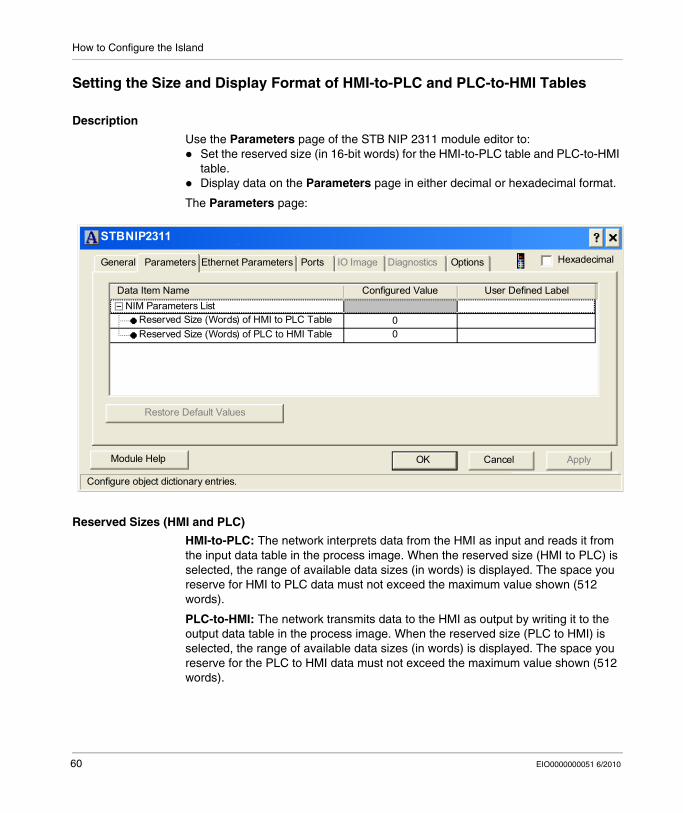
Setting the Size and Display Format of HMI-to-PLC and PLC-to-HMI Tables
Description
Use the Parameters page of the STB NIP 2311 module editor to:Set the reserved size (in 16-bit words) for the HMI-to-PLC table and PLC-to-HMI table.Display data on the Parameters page in either decimal or hexadecimal format.
The Parameters page:
Reserved Sizes (HMI and PLC)
HMI-to-PLC: The network interprets data from the HMI as input and reads it from the input data table in the process image. When the reserved size (HMI to PLC) is selected, the range of available data sizes (in words) is displayed. The space you reserve for HMI to PLC data must not exceed the maximum value shown (512 words).
PLC-to-HMI: The network transmits data to the HMI as output by writing it to the output data table in the process image. When the reserved size (PLC to HMI) is selected, the range of available data sizes (in words) is displayed. The space you reserve for the PLC to HMI data must not exceed the maximum value shown (512 words).
STBNIP2311
General Parameters Ethernet Parameters Ports OptionsIO Image Diagnostics
Data Item Name Configured Value User Defined Label
Restore Default Values
ApplyOK CancelModule Help
Configure object dictionary entries.
NIM Parameters ListReserved Size (Words) of HMI to PLC TableReserved Size (Words) of PLC to HMI Table
00
Hexadecimal
60 EIO0000000051 6/2010
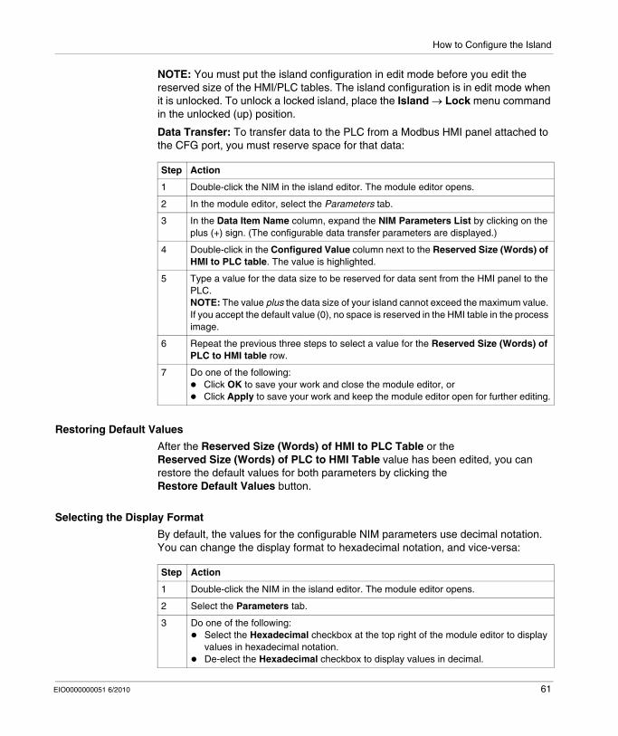
How to Configure the Island
NOTE: You must put the island configuration in edit mode before you edit the reserved size of the HMI/PLC tables. The island configuration is in edit mode when it is unlocked. To unlock a locked island, place the Island → Lock menu command in the unlocked (up) position.
Data Transfer: To transfer data to the PLC from a Modbus HMI panel attached to the CFG port, you must reserve space for that data:
Restoring Default Values
After the Reserved Size (Words) of HMI to PLC Table or the Reserved Size (Words) of PLC to HMI Table value has been edited, you can restore the default values for both parameters by clicking the Restore Default Values button.
Selecting the Display Format
By default, the values for the configurable NIM parameters use decimal notation. You can change the display format to hexadecimal notation, and vice-versa:
Step Action
1 Double-click the NIM in the island editor. The module editor opens.
2 In the module editor, select the Parameters tab.
3 In the Data Item Name column, expand the NIM Parameters List by clicking on the plus (+) sign. (The configurable data transfer parameters are displayed.)
4 Double-click in the Configured Value column next to the Reserved Size (Words) of HMI to PLC table. The value is highlighted.
5 Type a value for the data size to be reserved for data sent from the HMI panel to the PLC.NOTE: The value plus the data size of your island cannot exceed the maximum value. If you accept the default value (0), no space is reserved in the HMI table in the process image.
6 Repeat the previous three steps to select a value for the Reserved Size (Words) of PLC to HMI table row.
7 Do one of the following:Click OK to save your work and close the module editor, orClick Apply to save your work and keep the module editor open for further editing.
Step Action
1 Double-click the NIM in the island editor. The module editor opens.
2 Select the Parameters tab.
3 Do one of the following:Select the Hexadecimal checkbox at the top right of the module editor to display values in hexadecimal notation.De-elect the Hexadecimal checkbox to display values in decimal.
EIO0000000051 6/2010 61
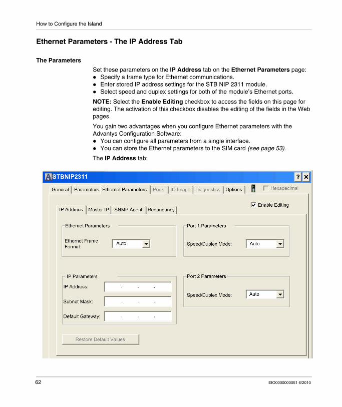
How to Configure the Island
Ethernet Parameters - The IP Address Tab
The Parameters
Set these parameters on the IP Address tab on the Ethernet Parameters page:Specify a frame type for Ethernet communications.Enter stored IP address settings for the STB NIP 2311 module.Select speed and duplex settings for both of the module’s Ethernet ports.
NOTE: Select the Enable Editing checkbox to access the fields on this page for editing. The activation of this checkbox disables the editing of the fields in the Web pages.
You gain two advantages when you configure Ethernet parameters with the Advantys Configuration Software:
You can configure all parameters from a single interface.You can store the Ethernet parameters to the SIM card (see page 53).
The IP Address tab:
62 EIO0000000051 6/2010
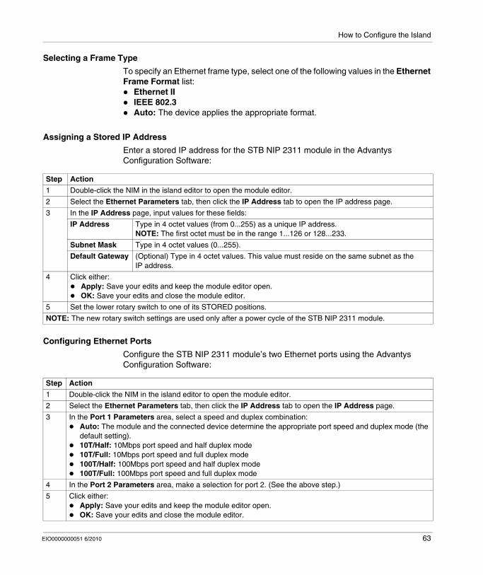
How to Configure the Island
Selecting a Frame Type
To specify an Ethernet frame type, select one of the following values in the Ethernet Frame Format list:
Ethernet IIIEEE 802.3Auto: The device applies the appropriate format.
Assigning a Stored IP Address
Enter a stored IP address for the STB NIP 2311 module in the Advantys Configuration Software:
Configuring Ethernet Ports
Configure the STB NIP 2311 module’s two Ethernet ports using the Advantys Configuration Software:
Step Action
1 Double-click the NIM in the island editor to open the module editor.
2 Select the Ethernet Parameters tab, then click the IP Address tab to open the IP address page.
3 In the IP Address page, input values for these fields:
IP Address Type in 4 octet values (from 0...255) as a unique IP address.NOTE: The first octet must be in the range 1...126 or 128...233.
Subnet Mask Type in 4 octet values (0...255).
Default Gateway (Optional) Type in 4 octet values. This value must reside on the same subnet as the IP address.
4 Click either:Apply: Save your edits and keep the module editor open.OK: Save your edits and close the module editor.
5 Set the lower rotary switch to one of its STORED positions.
NOTE: The new rotary switch settings are used only after a power cycle of the STB NIP 2311 module.
Step Action
1 Double-click the NIM in the island editor to open the module editor.
2 Select the Ethernet Parameters tab, then click the IP Address tab to open the IP Address page.
3 In the Port 1 Parameters area, select a speed and duplex combination:Auto: The module and the connected device determine the appropriate port speed and duplex mode (the default setting).10T/Half: 10Mbps port speed and half duplex mode10T/Full: 10Mbps port speed and full duplex mode100T/Half: 100Mbps port speed and half duplex mode100T/Full: 100Mbps port speed and full duplex mode
4 In the Port 2 Parameters area, make a selection for port 2. (See the above step.)
5 Click either:Apply: Save your edits and keep the module editor open.OK: Save your edits and close the module editor.
EIO0000000051 6/2010 63
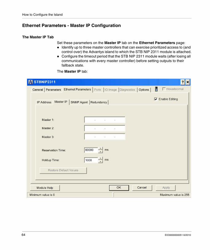
How to Configure the Island
Ethernet Parameters - Master IP Configuration
The Master IP Tab
Set these parameters on the Master IP tab on the Ethernet Parameters page:Identify up to three master controllers that can exercise prioritized access to (and control over) the Advantys island to which the STB NIP 2311 module is attached.Configure the timeout period that the STB NIP 2311 module waits (after losing all communications with every master controller) before setting outputs to their fallback state.
The Master IP tab:
64 EIO0000000051 6/2010
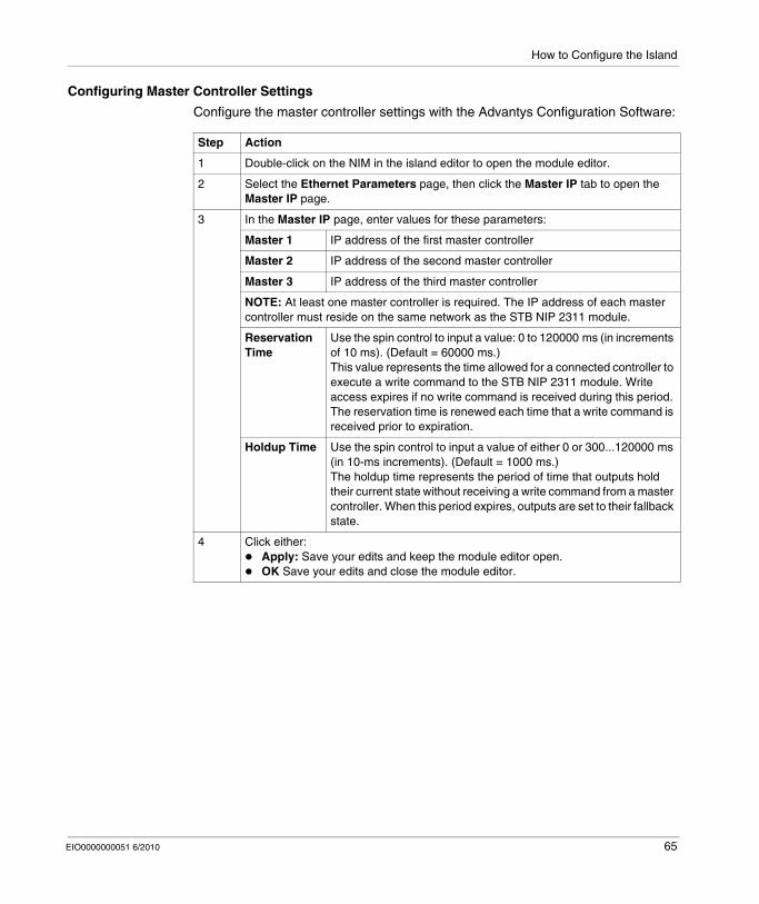
How to Configure the Island
Configuring Master Controller Settings
Configure the master controller settings with the Advantys Configuration Software:
Step Action
1 Double-click on the NIM in the island editor to open the module editor.
2 Select the Ethernet Parameters page, then click the Master IP tab to open the Master IP page.
3 In the Master IP page, enter values for these parameters:
Master 1 IP address of the first master controller
Master 2 IP address of the second master controller
Master 3 IP address of the third master controller
NOTE: At least one master controller is required. The IP address of each master controller must reside on the same network as the STB NIP 2311 module.
Reservation Time
Use the spin control to input a value: 0 to 120000 ms (in increments of 10 ms). (Default = 60000 ms.)This value represents the time allowed for a connected controller to execute a write command to the STB NIP 2311 module. Write access expires if no write command is received during this period. The reservation time is renewed each time that a write command is received prior to expiration.
Holdup Time Use the spin control to input a value of either 0 or 300...120000 ms (in 10-ms increments). (Default = 1000 ms.)The holdup time represents the period of time that outputs hold their current state without receiving a write command from a master controller. When this period expires, outputs are set to their fallback state.
4 Click either:Apply: Save your edits and keep the module editor open.OK Save your edits and close the module editor.
EIO0000000051 6/2010 65
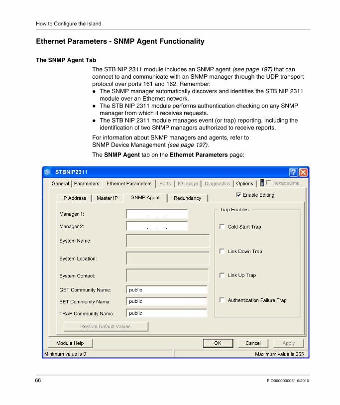
How to Configure the Island
Ethernet Parameters - SNMP Agent Functionality
The SNMP Agent Tab
The STB NIP 2311 module includes an SNMP agent (see page 197) that can connect to and communicate with an SNMP manager through the UDP transport protocol over ports 161 and 162. Remember:
The SNMP manager automatically discovers and identifies the STB NIP 2311 module over an Ethernet network.The STB NIP 2311 module performs authentication checking on any SNMP manager from which it receives requests.The STB NIP 2311 module manages event (or trap) reporting, including the identification of two SNMP managers authorized to receive reports.
For information about SNMP managers and agents, refer to SNMP Device Management (see page 197).
The SNMP Agent tab on the Ethernet Parameters page:
66 EIO0000000051 6/2010

How to Configure the Island
Configuring SNMP Agent Settings
Step Action
1 Double-click the NIM in the island editor to open the module editor.
2 Select the Ethernet Parameters page, then select the SNMP Agent tab to configure the SNMP agent parameters.
3 In the Manager’s IP Address section, enter these IP addresses:
Manager 1 The first SNMP manager’s IP address contains 4 octet decimal values from 0...255. To use SNMP, you must configure an IP address for manager 1.
Manager 2 Manager 2 represents the IP address of the second SNMP manager.
NOTE: The first octet value of each SNMP manager IP address must be either in the range 1...126 or 128...223.
4 The following Agent fields are read-only. (The fields contain case-sensitive ASCII strings with a 32-character maximum.):
System Name This user-defined string describes the STB NIP 2311 module.
System Location This string describes the location of the STB NIP 2311 module.
System Contact This string identifies the contact person for the STB NIP 2311 module.
5 In the Community Names section, enter the following passwords:
Get The Get, Set, and Trap passwords contain a maximum of 26 printable ASCII characters. (You can leave these passwords empty.)NOTE: The default setting for each community name is public.
Set
Trap
6 In the Enabled Traps section, select one or more of the following traps to enable reporting of that trap by the SNMP agent. De-select a trap to disable reporting.
Cold Start Trap The agent is re-initializing and its configuration may be altered.
Link Down Trap One of the agent’s communication links has turned off.
Link Up Trap One of the agent’s communication links has turned on.
Authentication Failure Trap
The agent received a request from an unauthorized manager.
7 Click one of the following:Apply: Save your edits and keep the module editor open.OK: Save your edits and close the module editor.
EIO0000000051 6/2010 67
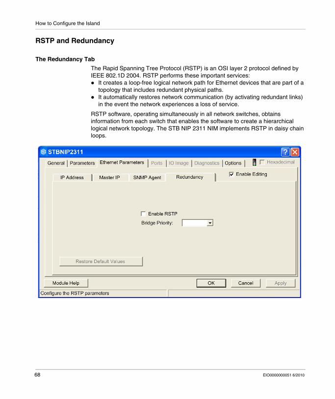
How to Configure the Island
RSTP and Redundancy
The Redundancy Tab
The Rapid Spanning Tree Protocol (RSTP) is an OSI layer 2 protocol defined by IEEE 802.1D 2004. RSTP performs these important services:
It creates a loop-free logical network path for Ethernet devices that are part of a topology that includes redundant physical paths.It automatically restores network communication (by activating redundant links) in the event the network experiences a loss of service.
RSTP software, operating simultaneously in all network switches, obtains information from each switch that enables the software to create a hierarchical logical network topology. The STB NIP 2311 NIM implements RSTP in daisy chain loops.
68 EIO0000000051 6/2010
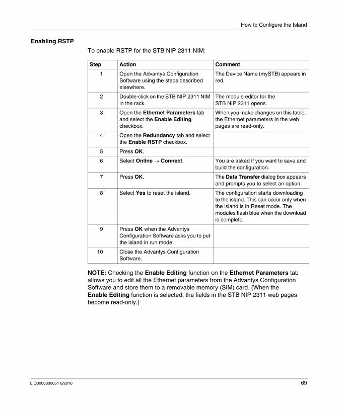
How to Configure the Island
Enabling RSTP
To enable RSTP for the STB NIP 2311 NIM:
NOTE: Checking the Enable Editing function on the Ethernet Parameters tab allows you to edit all the Ethernet parameters from the Advantys Configuration Software and store them to a removable memory (SIM) card. (When the Enable Editing function is selected, the fields in the STB NIP 2311 web pages become read-only.)
Step Action Comment
1 Open the Advantys Configuration Software using the steps described elsewhere.
The Device Name (mySTB) appears in red.
2 Double-click on the STB NIP 2311 NIM in the rack.
The module editor for the STB NIP 2311 opens.
3 Open the Ethernet Parameters tab and select the Enable Editing checkbox.
When you make changes on this table, the Ethernet parameters in the web pages are read-only.
4 Open the Redundancy tab and select the Enable RSTP checkbox.
5 Press OK.
6 Select Online → Connect. You are asked if you want to save and build the configuration.
7 Press OK. The Data Transfer dialog box appears and prompts you to select an option.
8 Select Yes to reset the island. The configuration starts downloading to the island. This can occur only when the island is in Reset mode. The modules flash blue when the download is complete.
9 Press OK when the Advantys Configuration Software asks you to put the island in run mode.
10 Close the Advantys Configuration Software.
EIO0000000051 6/2010 69
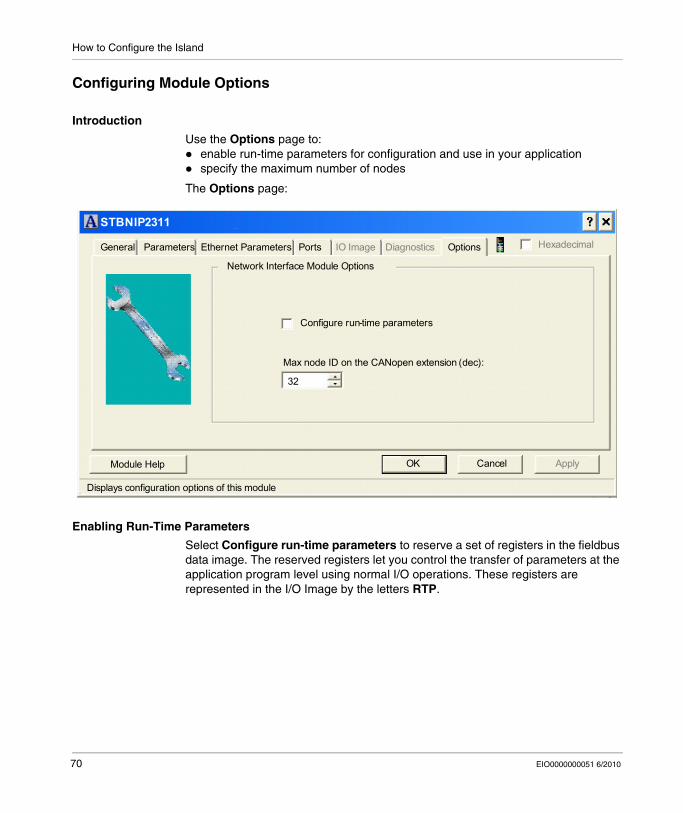
How to Configure the Island
Configuring Module Options
Introduction
Use the Options page to:enable run-time parameters for configuration and use in your applicationspecify the maximum number of nodes
The Options page:
Enabling Run-Time Parameters
Select Configure run-time parameters to reserve a set of registers in the fieldbus data image. The reserved registers let you control the transfer of parameters at the application program level using normal I/O operations. These registers are represented in the I/O Image by the letters RTP.
STBNIP2311
General Parameters Ethernet Parameters Ports OptionsIO Image Diagnostics
ApplyOK CancelModule Help
Displays configuration options of this module
Hexadecimal
Network Interface Module Options
Configure run-time parameters
Max node ID on the CANopen extension (dec):
32
70 EIO0000000051 6/2010

How to Configure the Island
Assigning the Max. Node ID (CANopen Devices)
In the Options page, you can set the maximum node ID of the last module on the island bus. The last module may be an enhanced CANopen device. Enhanced CANopen devices follow the last segment of STB I/O modules. CANopen modules are addressed by counting backwards from the value that you specify here. The ideal node ID sequence is sequential.
For example, if you have an island with five STB I/O modules and three CANopen devices, a maximum node ID of at least 8 (5 + 3) is required. This results in node IDs of 1 through 5 for STB I/O modules and 6 through 8 for enhanced CANopen devices. The default ID of 32 (the maximum number of modules the island can support) results in node IDs of 1 through 5 for STB I/O modules and 30 through 32 for enhanced CANopen devices. Unless required, high addresses are not desirable if one (or more) of your enhanced CANopen devices has a limited address range.
Assign the highest node ID used by a CANopen device on the island bus:
Step Action
1 In the module editor, select the Options tab.
2 Set a value in the Max. node ID on the CANopen extension field using the spin control.
EIO0000000051 6/2010 71

How to Configure the Island
72 EIO0000000051 6/2010

EIO0000000051 6/2010
4
How to Obtain IP Parameters for the STB NIP 2311
EIO0000000051 6/2010
How to Obtain IP Parameters for the STB NIP 2311
About this Chapter
This chapter describes the assignment of IP parameters to the STB NIP 2311 NIM. Each network address must be valid and unique on the network.
What's in this Chapter?
This chapter contains the following topics:
Topic Page
How Does the STB NIP 2311 Obtain IP Parameters? 74
The IP Address Assignment Flowchart 76
73
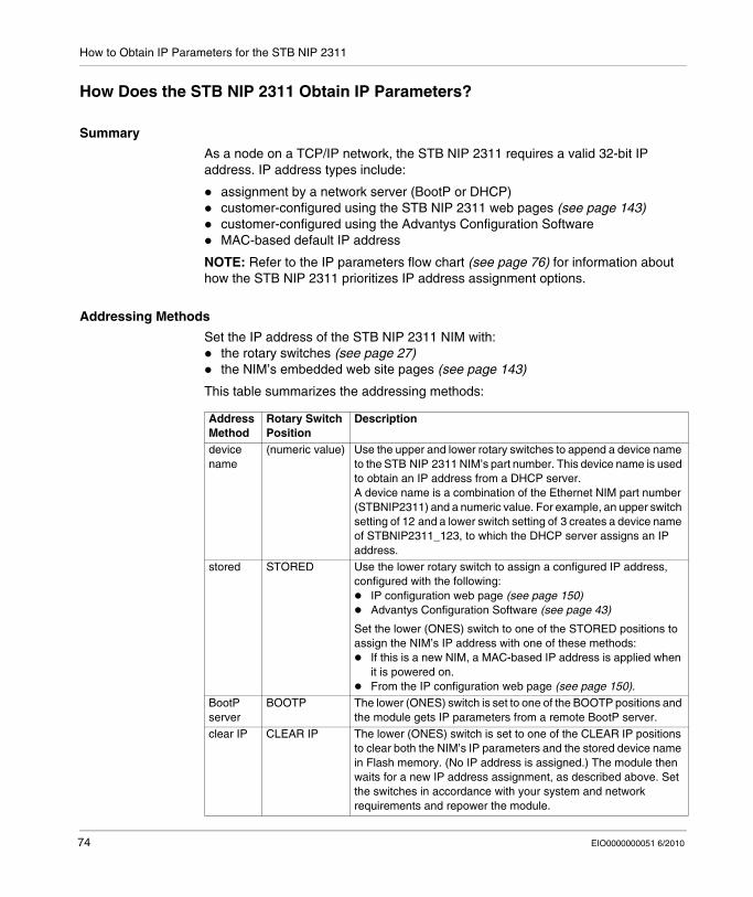
How to Obtain IP Parameters for the STB NIP 2311
How Does the STB NIP 2311 Obtain IP Parameters?
Summary
As a node on a TCP/IP network, the STB NIP 2311 requires a valid 32-bit IP address. IP address types include:
assignment by a network server (BootP or DHCP)customer-configured using the STB NIP 2311 web pages (see page 143)customer-configured using the Advantys Configuration SoftwareMAC-based default IP address
NOTE: Refer to the IP parameters flow chart (see page 76) for information about how the STB NIP 2311 prioritizes IP address assignment options.
Addressing Methods
Set the IP address of the STB NIP 2311 NIM with:the rotary switches (see page 27)the NIM’s embedded web site pages (see page 143)
This table summarizes the addressing methods:
Address Method
Rotary Switch Position
Description
device name
(numeric value) Use the upper and lower rotary switches to append a device name to the STB NIP 2311 NIM’s part number. This device name is used to obtain an IP address from a DHCP server.A device name is a combination of the Ethernet NIM part number (STBNIP2311) and a numeric value. For example, an upper switch setting of 12 and a lower switch setting of 3 creates a device name of STBNIP2311_123, to which the DHCP server assigns an IP address.
stored STORED Use the lower rotary switch to assign a configured IP address, configured with the following:
IP configuration web page (see page 150)Advantys Configuration Software (see page 43)
Set the lower (ONES) switch to one of the STORED positions to assign the NIM’s IP address with one of these methods:
If this is a new NIM, a MAC-based IP address is applied when it is powered on.From the IP configuration web page (see page 150).
BootP server
BOOTP The lower (ONES) switch is set to one of the BOOTP positions and the module gets IP parameters from a remote BootP server.
clear IP CLEAR IP The lower (ONES) switch is set to one of the CLEAR IP positions to clear both the NIM’s IP parameters and the stored device name in Flash memory. (No IP address is assigned.) The module then waits for a new IP address assignment, as described above. Set the switches in accordance with your system and network requirements and repower the module.
74 EIO0000000051 6/2010

How to Obtain IP Parameters for the STB NIP 2311
Deriving an IP Address from a MAC Address
When the STB NIP 2311 requests an IP address from a BootP or DHCP server but does not receive a response, it uses a default IP address that is derived from its factory-assigned MAC address. (The MAC address for an STB NIP 2311 is displayed above the Ethernet ports on the front of the module.)
The 32-bit default IP address contains the values in the last 2 octets of the module's 48-bit factory-assigned MAC address. The default address observes the format 10.10.x.y., where x and y are derived from the last 2 octets of the MAC address. Convert these 2 octets from hexadecimal to decimal format to understand the IP address that the module is using for network communications:
NOTE: There are many resources for converting hex numbers to decimal numbers. We recommend using the Windows calculator in scientific mode.
NOTE: An IP address is derived from the MAC address only when the IP address is not otherwise provided by:
a BootP or DHCP servera user configured IP setting
Step Action
1 Using a sample MAC address of 00-00-54-10-25-16, ignore the first four pairs (00-00-54-10).
2 Convert the subsequent pairs (25 and 16) from hexadecimal to decimal format.
25: (2 x 16) + 5 = 37
16: (1 x 16) + 6 = 22
3 Observe the specified format (10.10.x.y.) to assemble the derived default IP address.
The default IP address is: 10.10.37.22
EIO0000000051 6/2010 75
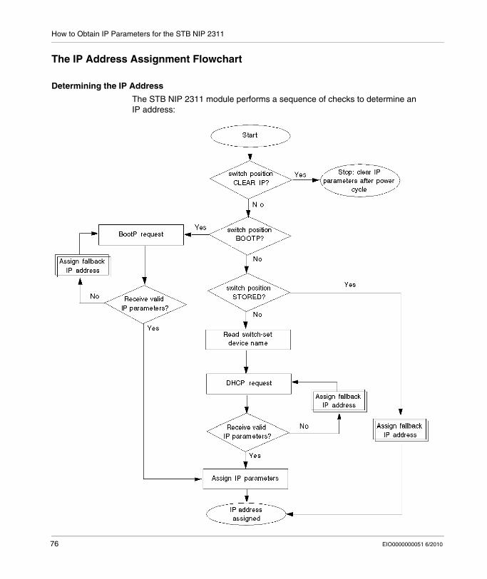
How to Obtain IP Parameters for the STB NIP 2311
The IP Address Assignment Flowchart
Determining the IP Address
The STB NIP 2311 module performs a sequence of checks to determine an IP address:
76 EIO0000000051 6/2010
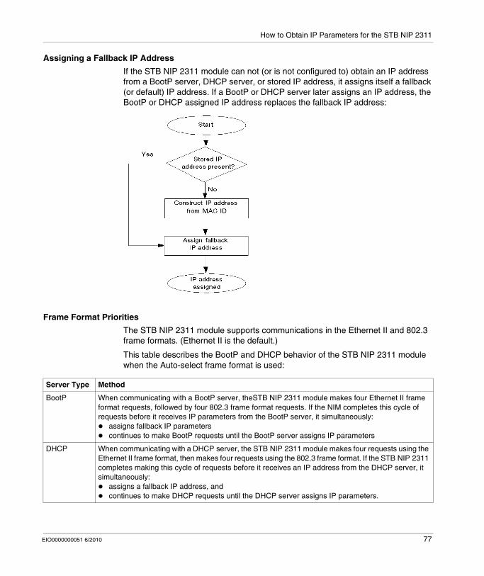
How to Obtain IP Parameters for the STB NIP 2311
Assigning a Fallback IP Address
If the STB NIP 2311 module can not (or is not configured to) obtain an IP address from a BootP server, DHCP server, or stored IP address, it assigns itself a fallback (or default) IP address. If a BootP or DHCP server later assigns an IP address, the BootP or DHCP assigned IP address replaces the fallback IP address:
Frame Format Priorities
The STB NIP 2311 module supports communications in the Ethernet II and 802.3 frame formats. (Ethernet II is the default.)
This table describes the BootP and DHCP behavior of the STB NIP 2311 module when the Auto-select frame format is used:
Server Type Method
BootP When communicating with a BootP server, theSTB NIP 2311 module makes four Ethernet II frame format requests, followed by four 802.3 frame format requests. If the NIM completes this cycle of requests before it receives IP parameters from the BootP server, it simultaneously:
assigns fallback IP parameterscontinues to make BootP requests until the BootP server assigns IP parameters
DHCP When communicating with a DHCP server, the STB NIP 2311 module makes four requests using the Ethernet II frame format, then makes four requests using the 802.3 frame format. If the STB NIP 2311 completes making this cycle of requests before it receives an IP address from the DHCP server, it simultaneously:
assigns a fallback IP address, andcontinues to make DHCP requests until the DHCP server assigns IP parameters.
EIO0000000051 6/2010 77

How to Obtain IP Parameters for the STB NIP 2311
78 EIO0000000051 6/2010
EIO0000000051 6/2010
5
Optimizing Performance
EIO0000000051 6/2010
Optimizing Performance
Overview
This chapter describes how to optimize the performance of your Ethernet network.
What's in this Chapter?
This chapter contains the following sections:
Section Topic Page
5.1 Selecting a Switch 80
5.2 Control Application Design 91
5.3 Projecting Ethernet Network Performance 105
79
Optimizing Performance
5.1 Selecting a Switch
Overview
This section describes how to select an Ethernet switch for your network.
What's in this Section?
This section contains the following topics:
Topic Page
Role of a Switch in an Ethernet Network 81
Transmission Speed, Duplex and Auto-Negotiation 82
Quality of Service (QoS) 83
IGMP Snooping 84
Rapid Spanning Tree Protocol (RSTP) 85
Virtual Local Area Network (VLAN) 86
Port Mirroring 88
Simple Network Management Protocol (SNMP) Agent 90
80 EIO0000000051 6/2010
Optimizing Performance
Role of a Switch in an Ethernet Network
Overview
Schneider Electric recommends the use of managed switches—not unmanaged switches or hubs—in process control networks. A managed switch provides more functionality than an unmanaged switch, including the ability to:
turn switch ports on or offconfigure port speed and duplex settingscontrol and monitor message traffic within segmentsprioritize message traffic
Recommended Switch Features
When acquiring an Ethernet switch for your process control network, be sure the switch includes the following features:
Multiple speed (10/100/1000 Mbps)Full duplexQoSIGMP snoopingRSTPVLAN supportPort mirroringSNMP agent
EIO0000000051 6/2010 81
Optimizing Performance
Transmission Speed, Duplex and Auto-Negotiation
Introduction
Most Ethernet switches support multiple transmission speeds, full- and half-duplex communication, and offer auto-negotiation capability. Hubs, by contrast, do not support full duplex transmissions.
Duplex
Full duplex enables a switch port to both transmit and receive messages simultaneously, over two dedicated communication channels. Half duplex, instead only permits a port to transmit or receive messages at one time. Half duplex communication presents the risk of signal collisions—as messages are both received and transmitted over a single channel—and can result in poor performance and message loss.
Auto-Negotiation
Auto-negotiation permits a switch port—connected to a remote device that also supports auto-negotiation—to automatically configure itself for the maximum speed and duplex configuration supported by both devices. However, it may be necessary to manually configure the speed and duplex settings of the switch port, if its peer device does not possess auto-negotiation capability.
Recommendation
Schneider Electric recommends that you employ only switches that support:both auto-negotiation and manual configuration of speed and duplex settingsmultiple speeds: 10/100/1000 Mbpsboth full duplex and half duplex
82 EIO0000000051 6/2010

Optimizing Performance
Quality of Service (QoS)
Introduction
A switch that supports QoS packet tagging can be configured to deliver higher priority messages before messages with a lower (or no) priority. This enhances system determinism and increases the timely delivery of prioritized messages.
In the absence of QoS tagging, the switch delivers various application messages on a first-in first-out basis. This can result in poor system performance caused by the long forwarding delay—and late delivery—of important application messages, which may be handled after less important messages.
Types of QoS
The tagging types are based on the switch configuration:
Recommendation
Schneider Electric recommends the use of devices—including switches—that support explicit QoS tagging.
NOTE: Some switches that support QoS tagging have this feature disabled by default. Be sure to enable QoS when deploying each switch.
Tagging type Priority mapping rule Description
Explicit (QoS tag in Ethernet packet)
DSCP or TOS field in IP header
Each IP based Ethernet packet contains a value in the DSCP or TOS field in its IP header, indicating the QoS priority. The switch forwards packets based on this priority.
VLAN tag in Ethernet header
Each Ethernet packet contains a value in the priority field in the VLAN tag in its Ethernet header, indicating the QoS priority. The switch forwards packets based on this priority.
Implicit Port based Switch ports are mapped to different QoS priorities. For example, switch port 1 is mapped to QoS priority 1, switch port 2 is mapped to QoS priority 2, etc.
EIO0000000051 6/2010 83

Optimizing Performance
IGMP Snooping
Multicast Messaging
Internet Group Management Protocol (IGMP) is an essential feature of multicast messaging. IGMP instructs routers and switches to forward Ethernet multicast packets to only those device ports that have requested these packets.
In the absence of IGMP snooping, a switch forwards multicast packets out of all its ports, resulting in greater network traffic, wasted network bandwidth, and degraded network performance.
Be sure to configure one Ethernet network switch as the IGMP querier. This switch periodically polls the field devices connected to the network, which causes all connected devices to issue an IGMP Multicast Group Join message. The group message is received by all network switches, which update their multicast addressing information databases in response.
Similarly, when an Ethernet device transmits an IGMP Multicast Group Leave message, all network switches update their multicast addressing information databases by removing the device from their databases.
Multicast messaging reduces network traffic by:
requiring that a message be sent only oncesending the message only to devices for which the message is intended
Recommendation
Schneider Electric recommend the following:employ switches that support IGMP V2 or higherbecause IGMP snooping may be disabled by default, be sure to enable IGMP snooping for each network switchbe sure that one switch is configured as the IGMP querier
84 EIO0000000051 6/2010
Optimizing Performance
Rapid Spanning Tree Protocol (RSTP)
Recommendations
Schneider Electric recommends these practices:Use RSTP instead of STP. RSTP provides a faster recovery time than STP. NOTE: Recovery time is the elapsed time between the moment a loss of service is detected and the moment network service is restored. Recovery time depends on:
number of switches: Higher numbers of switches in the topology result in higher recovery times.switch speed: Switches in the topology with slower processing speeds result in longer recovery times.bandwidthtraffic loadtopology pattern
Enable RSTP when the switch is part of a topology with redundant physical paths.Disable RSTP when the switch is part of a topology that does not include redundant physical paths. Disabling RSTP in this situation can improve network performance.When you configure a daisy chain loop topology, the Max Age of the root bridge must be set to the number of nodes in the loop plus 1. That is, a loop with 21 nodes should have a Max Age of at least 22.
EIO0000000051 6/2010 85
Optimizing Performance
Virtual Local Area Network (VLAN)
Introduction
Use VLANs to divide a larger network into smaller virtual groups of devices, and to split a switch into many virtual network switches. VLANs permit the creation of logically separate groups of network devices, without having to physically re-wire those devices.
When a switch receives a message directed to a specific VLAN, it forwards that message only to the switch ports connected to devices that are members of that VLAN. The switch does not send the message to other ports.
A VLAN reduces network traffic, blocks multicast and broadcast traffic from unintended VLANs, provides security between VLANs, and improves system performance.
VLAN Types
Depending upon the switch features, there many different ways to define and implement VLANs:
Tagging type Mapping rule Description
Explicit (VLAN tag in Ethernet packet)
Tag based Each VLAN group is assigned a unique VLAN ID, which is included in each Ethernet packet. The switch forwards packets based on VLAN ID.
Implicit (no VLAN tag in Ethernet packet)
Port based Switch ports are assigned to different VLANs, when the switch is configured (see example, below.)
MAC based A switch maps VLAN group membership—and forwards Ethernet frames—based on device MAC address.
Protocol based A switch maps VLAN group membership—and forwards Ethernet frames—based on message protocol.
IP-subnet based A switch maps VLAN group membership—and forwards Ethernet frames—based on IP subnet portion of the target address.
86 EIO0000000051 6/2010
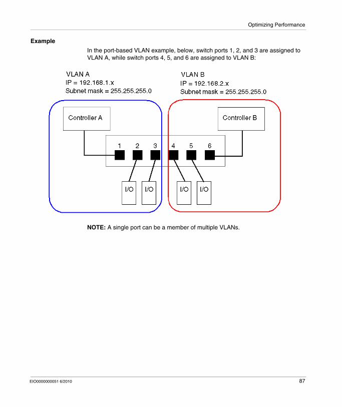
Optimizing Performance
Example
In the port-based VLAN example, below, switch ports 1, 2, and 3 are assigned to VLAN A, while switch ports 4, 5, and 6 are assigned to VLAN B:
NOTE: A single port can be a member of multiple VLANs.
EIO0000000051 6/2010 87
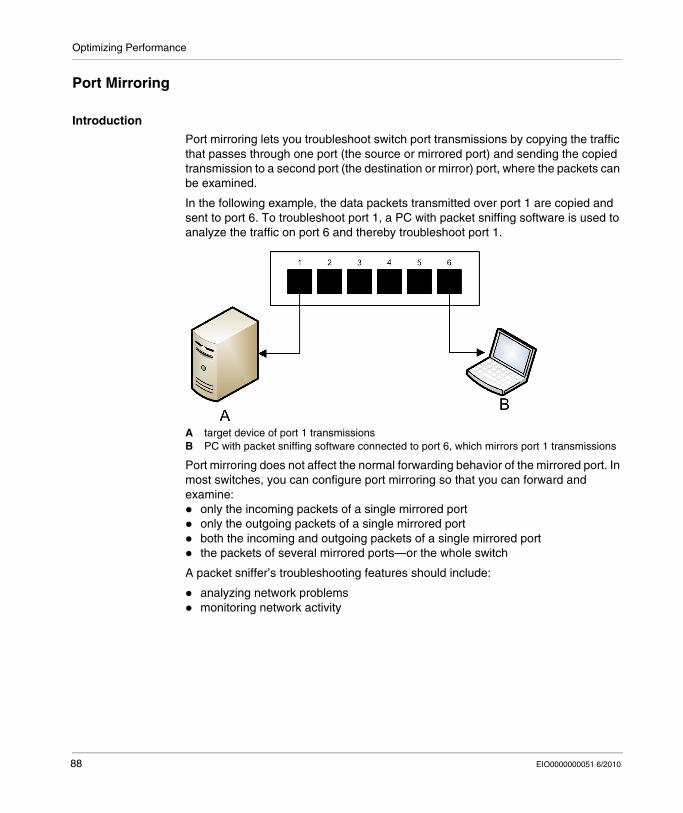
Optimizing Performance
Port Mirroring
Introduction
Port mirroring lets you troubleshoot switch port transmissions by copying the traffic that passes through one port (the source or mirrored port) and sending the copied transmission to a second port (the destination or mirror) port, where the packets can be examined.
In the following example, the data packets transmitted over port 1 are copied and sent to port 6. To troubleshoot port 1, a PC with packet sniffing software is used to analyze the traffic on port 6 and thereby troubleshoot port 1.
A target device of port 1 transmissionsB PC with packet sniffing software connected to port 6, which mirrors port 1 transmissions
Port mirroring does not affect the normal forwarding behavior of the mirrored port. In most switches, you can configure port mirroring so that you can forward and examine:
only the incoming packets of a single mirrored portonly the outgoing packets of a single mirrored portboth the incoming and outgoing packets of a single mirrored portthe packets of several mirrored ports—or the whole switch
A packet sniffer’s troubleshooting features should include:
analyzing network problemsmonitoring network activity
88 EIO0000000051 6/2010

Optimizing Performance
Recommendation
Schneider Electric recommends implementing port mirroring as follows:A destination or mirror port should be used only for port mirroring; it should not be used for any other purpose. Only the PC with packet sniffer should be connected to the mirroring port.When configuring the switch, be sure that port mirroring is designed to forward packets—e.g., incoming, outgoing, or both—to meet your requirements.A packet sniffer’s troubleshooting features should include the capabilities of analyzing network problems and monitoring network activity.
EIO0000000051 6/2010 89

Optimizing Performance
Simple Network Management Protocol (SNMP) Agent
An SNMP agent is a software component that responds to queries about the management data of the switch, and reports events to another device acting as an SNMP manager.
The management data for a switch can include:operational state information (interface status, mode of operation, etc.)configuration parameters (IP address, features enabled / disabled, timer values, etc.)performance statistics (frame counters, event logs, etc.)
If a switch is equipped with SNMP agent software, a designated SNMP manager can:
retrieve management data about the switchcontrol the switch by editing its configuration settingsreceive traps—or notices of events—affecting the state of the switch
90 EIO0000000051 6/2010
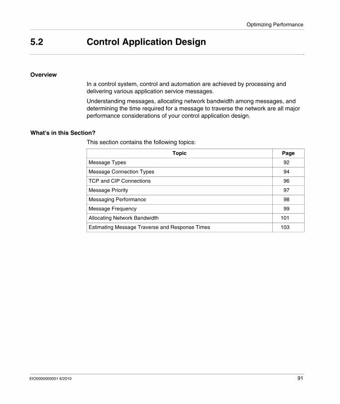
Optimizing Performance
5.2 Control Application Design
Overview
In a control system, control and automation are achieved by processing and delivering various application service messages.
Understanding messages, allocating network bandwidth among messages, and determining the time required for a message to traverse the network are all major performance considerations of your control application design.
What's in this Section?
This section contains the following topics:
Topic Page
Message Types 92
Message Connection Types 94
TCP and CIP Connections 96
Message Priority 97
Messaging Performance 98
Message Frequency 99
Allocating Network Bandwidth 101
Estimating Message Traverse and Response Times 103
EIO0000000051 6/2010 91
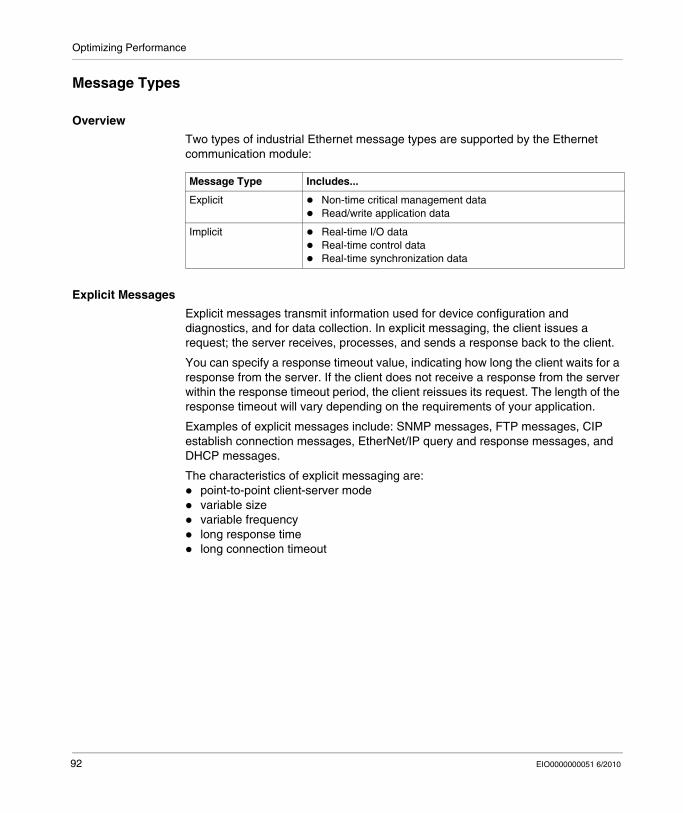
Optimizing Performance
Message Types
Overview
Two types of industrial Ethernet message types are supported by the Ethernet communication module:
Explicit Messages
Explicit messages transmit information used for device configuration and diagnostics, and for data collection. In explicit messaging, the client issues a request; the server receives, processes, and sends a response back to the client.
You can specify a response timeout value, indicating how long the client waits for a response from the server. If the client does not receive a response from the server within the response timeout period, the client reissues its request. The length of the response timeout will vary depending on the requirements of your application.
Examples of explicit messages include: SNMP messages, FTP messages, CIP establish connection messages, EtherNet/IP query and response messages, and DHCP messages.
The characteristics of explicit messaging are:point-to-point client-server modevariable sizevariable frequencylong response timelong connection timeout
Message Type Includes...
Explicit Non-time critical management dataRead/write application data
Implicit Real-time I/O dataReal-time control dataReal-time synchronization data
92 EIO0000000051 6/2010
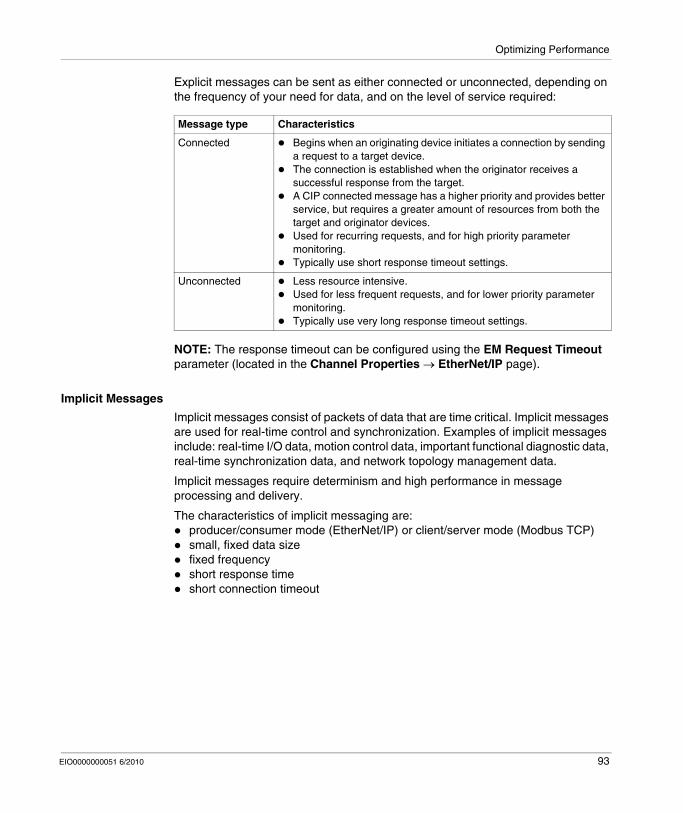
Optimizing Performance
Explicit messages can be sent as either connected or unconnected, depending on the frequency of your need for data, and on the level of service required:
NOTE: The response timeout can be configured using the EM Request Timeout parameter (located in the Channel Properties → EtherNet/IP page).
Implicit Messages
Implicit messages consist of packets of data that are time critical. Implicit messages are used for real-time control and synchronization. Examples of implicit messages include: real-time I/O data, motion control data, important functional diagnostic data, real-time synchronization data, and network topology management data.
Implicit messages require determinism and high performance in message processing and delivery.
The characteristics of implicit messaging are:producer/consumer mode (EtherNet/IP) or client/server mode (Modbus TCP)small, fixed data sizefixed frequencyshort response timeshort connection timeout
Message type Characteristics
Connected Begins when an originating device initiates a connection by sending a request to a target device.The connection is established when the originator receives a successful response from the target.A CIP connected message has a higher priority and provides better service, but requires a greater amount of resources from both the target and originator devices. Used for recurring requests, and for high priority parameter monitoring.Typically use short response timeout settings.
Unconnected Less resource intensive.Used for less frequent requests, and for lower priority parameter monitoring.Typically use very long response timeout settings.
EIO0000000051 6/2010 93

Optimizing Performance
Message Connection Types
Introduction
The transmission of most messages require a point-to-point connection between a transmitter and receiver.
For all types of explicit messages, the connection automatically closes when the communication ends, or is timed-out.
For implicit messages, the connection must be kept open. If the I/O connection—CIP for EtherNet/IP, TCP for Modbus TCP—the transmission stops. In this case, the scanner employs the TCP implicit messaging connection to dynamically re-establish the CIP connection.
Calculating the Connection Timeout
For CIP connections, you can control the connection timeout setting by specifying both the network multiplier and the requested packet interval (RPI in ms):
Timeout = Network Multiplier x RPI
NOTE: You can locate and configure these values in the Unity Pro Ethernet Configuration Tool. Open the DTM Editor for the Ethernet communication module, then edit the following settings:
the network multiple is the Time-out Multiplier parameter found in the Device List → <device> → <connection> → Connection Settings page, andthe RPI is the EM Connection RPI parameter found in the Channel Properties → EtherNet/IP page
A large timeout value may affect the ability of the network to optimize the availability of connection resources, re-establish connections, and update I/O data when the connection is lost.
A small timeout value may unnecessarily cause the frequent closing and re-establishing of connections.
It is preferable to use a larger timeout value for explicit messaging connections, and a smaller timeout value for implicit messaging connections. The specific value you employ depends on your application requirements.
94 EIO0000000051 6/2010
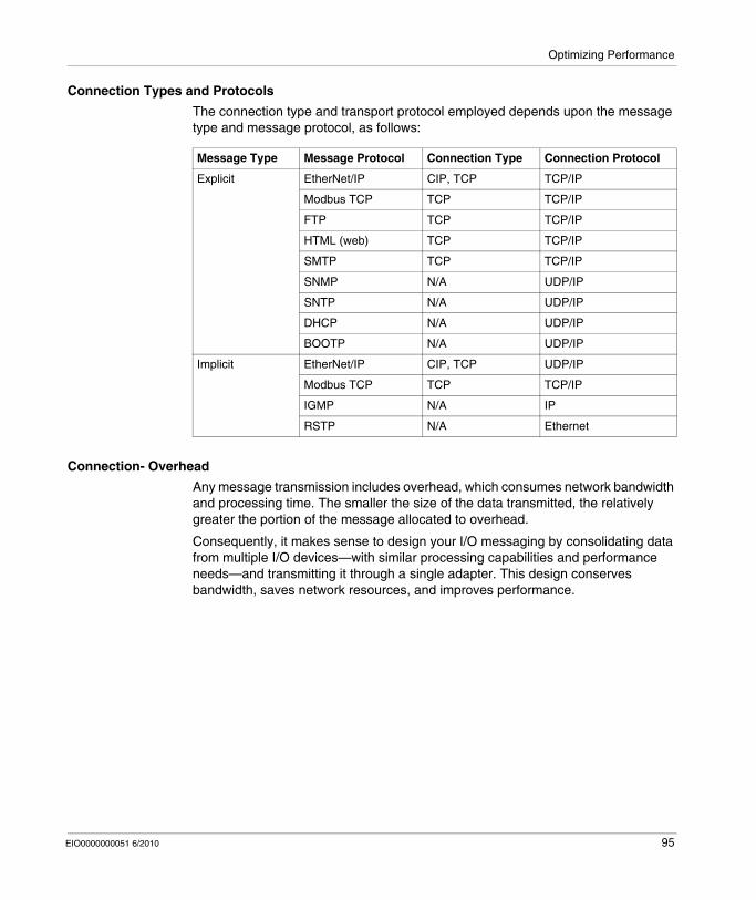
Optimizing Performance
Connection Types and Protocols
The connection type and transport protocol employed depends upon the message type and message protocol, as follows:
Connection- Overhead
Any message transmission includes overhead, which consumes network bandwidth and processing time. The smaller the size of the data transmitted, the relatively greater the portion of the message allocated to overhead.
Consequently, it makes sense to design your I/O messaging by consolidating data from multiple I/O devices—with similar processing capabilities and performance needs—and transmitting it through a single adapter. This design conserves bandwidth, saves network resources, and improves performance.
Message Type Message Protocol Connection Type Connection Protocol
Explicit EtherNet/IP CIP, TCP TCP/IP
Modbus TCP TCP TCP/IP
FTP TCP TCP/IP
HTML (web) TCP TCP/IP
SMTP TCP TCP/IP
SNMP N/A UDP/IP
SNTP N/A UDP/IP
DHCP N/A UDP/IP
BOOTP N/A UDP/IP
Implicit EtherNet/IP CIP, TCP UDP/IP
Modbus TCP TCP TCP/IP
IGMP N/A IP
RSTP N/A Ethernet
EIO0000000051 6/2010 95
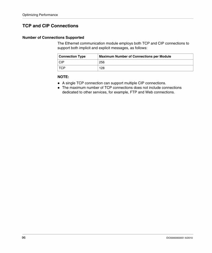
Optimizing Performance
TCP and CIP Connections
Number of Connections Supported
The Ethernet communication module employs both TCP and CIP connections to support both implicit and explicit messages, as follows:
NOTE:
A single TCP connection can support multiple CIP connections.The maximum number of TCP connections does not include connections dedicated to other services, for example, FTP and Web connections.
Connection Type Maximum Number of Connections per Module
CIP 256
TCP 128
96 EIO0000000051 6/2010

Optimizing Performance
Message Priority
QoS
The routers and switches that comprise your network infrastructure cannot distinguish between explicit message and implicit messages. However, these devices—including the Ethernet communication module—can support QoS Ethernet packet tagging.
Using Qos tagging, these devices can handle messages they send and receive according to each message’s tagged priority, forwarding higher priority messages before lower priority messages.
EIO0000000051 6/2010 97

Optimizing Performance
Messaging Performance
Maximum Messaging Load
The Ethernet communication module supports a the following maximum messaging loads:
Message Type Maximum Messaging Load
Implicit (EtherNet/IP plus Modbus TCP) 12000 packets per second, with no simultaneous explicit messages
Explicit (EtherNet/IP plus Modbus TCP) 120 packets per second, with a maximum of 6000 simultaneous implicit messages
98 EIO0000000051 6/2010
Optimizing Performance
Message Frequency
Introduction
The term message frequency refers to how often a device transmits a particular type of message. Message frequency directly affects control network load and performance, as well as the CPU capacity of every network device that must process these messages.
Depending on your application requirements, real-time I/O data can be transmitted using implicit messaging as follows:
on a cyclic basis, at the request packet interval (RPI) rate, orupon the occurrence of a change of state event
Cyclic Real-Time I/O Messaging
Most of the load on an Ethernet control network consists of cyclic real-time I/O data. Consequently, you must carefully consider how to set the RPI value for transmitting these messages:
A small RPI value results in more frequent, and more numerous, message transmissions. This increases network load, and may waste network resources and degrade system performance.Conversely, a larger RPI value—for example, one that is equal (or nearly equal) to the frequency of your application’s need for new data—can result in your application not receiving the most current data. Also, if a connection is lost, the time to re-establish the connection will be relatively long, because the connection timeout is proportional to the RPI.
Schneider Electric recommends setting RPI to 50% of the actual frequency by which your application requires data for cyclic real-time I/O messaging.
NOTE: The I/O scanner can simultaneously communicate with different I/O adapters at different RPI rates. This enhances the ability of the PLC to control and monitor different devices with varying processing capacities.
Change of State I/O Messaging
For change of state triggered real-time I/O data messages:output transmissions occur at the rate of the PLC controller application cycle timeinput transmissions occur whenever an input event is detected by an input device
Consequently, for an I/O device with a rapid response and transmission time, using a direct connection to the I/O device may be more efficient than using a rack optimized connection. In this design, because only the single device input data is sent, the size of the frequently transmitted message is potentially much smaller than would be the case if the message contained data from all I/O devices on the remote island.
NOTE: A change of state (versus cyclic) triggered real-time I/O message usually reduces network load, but must be configured with a longer connection timeout value.
EIO0000000051 6/2010 99
Optimizing Performance
RSTP and IGMP Messaging
RSTP and IGMP messages usually consume a very small amount of network bandwidth. Set up the IGMP query period based on your application requirements.
Scheduling Certain Explicit Messages
Depending on your application requirements, you can also configure certain explicit messages to be transmitted either cyclically or upon the occurrence of a change of state event. For example, you can periodically monitor a device using SNMP query, Web pages, EtherNet/IP, and Modbus TCP. The cyclic period should be configured so that the total load consumed by explicit messaging does not exceed 10% of network capacity.
100 EIO0000000051 6/2010
Optimizing Performance
Allocating Network Bandwidth
Introduction
Maximum network bandwidth equals your network speed, for example 100 Mbps. When designing your control network, you must allocate network bandwidth among the control application messages required by your application.
NOTE: Schneider Electric recommends you reserve at least the following amounts for processing explicit messaging:
10% of network bandwidth10% of CPU processing capacity for each network device
Message Load and Message Bandwidth
Message Load—in packets per second (PPS)—represents the number of packets in a single message that are received and sent within one second. Message Load can be estimated as follows:
Message Load =
(number of packets per connection) x (number of connections) / RPI
The number of packets per connection value depends on the capacity of the device, and can be either:
1: for connections that support uni-directional communication2: for connections that support input and output (for producer/consumer mode) or request and response (for client/server mode) per one time bi-directional exchange, or
The connection can be used for either explicit or implicit messaging. For UDP-based explicit messaging, assume that each client represents one connection, and that all messages are transmitted cyclically.
Message Bandwidth (in bits) can be calculated as follows:
Message Bandwidth = message packet size (bits) x Message Load
Based on the portion of network bandwidth you want to allocate to a particular message, you can use the Message Load and Message Bandwidth formulae to calculate the fastest RPI for the message.
EIO0000000051 6/2010 101
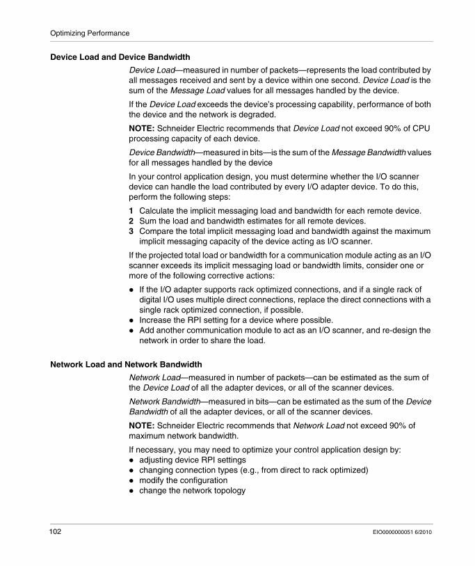
Optimizing Performance
Device Load and Device Bandwidth
Device Load—measured in number of packets—represents the load contributed by all messages received and sent by a device within one second. Device Load is the sum of the Message Load values for all messages handled by the device.
If the Device Load exceeds the device’s processing capability, performance of both the device and the network is degraded.
NOTE: Schneider Electric recommends that Device Load not exceed 90% of CPU processing capacity of each device.
Device Bandwidth—measured in bits—is the sum of the Message Bandwidth values for all messages handled by the device
In your control application design, you must determine whether the I/O scanner device can handle the load contributed by every I/O adapter device. To do this, perform the following steps:
1 Calculate the implicit messaging load and bandwidth for each remote device.2 Sum the load and bandwidth estimates for all remote devices.3 Compare the total implicit messaging load and bandwidth against the maximum
implicit messaging capacity of the device acting as I/O scanner.
If the projected total load or bandwidth for a communication module acting as an I/O scanner exceeds its implicit messaging load or bandwidth limits, consider one or more of the following corrective actions:
If the I/O adapter supports rack optimized connections, and if a single rack of digital I/O uses multiple direct connections, replace the direct connections with a single rack optimized connection, if possible.Increase the RPI setting for a device where possible.Add another communication module to act as an I/O scanner, and re-design the network in order to share the load.
Network Load and Network Bandwidth
Network Load—measured in number of packets—can be estimated as the sum of the Device Load of all the adapter devices, or all of the scanner devices.
Network Bandwidth—measured in bits—can be estimated as the sum of the Device Bandwidth of all the adapter devices, or all of the scanner devices.
NOTE: Schneider Electric recommends that Network Load not exceed 90% of maximum network bandwidth.
If necessary, you may need to optimize your control application design by:adjusting device RPI settingschanging connection types (e.g., from direct to rack optimized)modify the configurationchange the network topology
102 EIO0000000051 6/2010
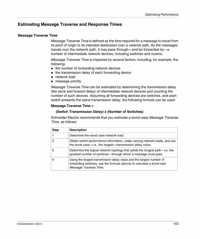
Optimizing Performance
Estimating Message Traverse and Response Times
Message Traverse Time
Message Traverse Time is defined as the time required for a message to travel from its point of origin to its intended destination over a network path. As the messages travels over the network path, it may pass through—and be forwarded by—a number of intermediate network devices, including switches and routers.
Message Traverse Time is impacted by several factors, including, for example, the following:
the number of forwarding network devicesthe transmission delay of each forwarding devicenetwork loadmessage priority
Message Traverse Time can be estimated by determining the transmission delay (the store and forward delay) of intermediate network devices and counting the number of such devices. Assuming all forwarding devices are switches, and each switch presents the same transmission delay, the following formula can be used:
Message Traverse Time =
(Switch Transmission Delay) x (Number of Switches)
Schneider Electric recommends that you estimate a worst-case Message Traverse Time, as follows:
Step Description
1 Determine the worst case network load.
2 Obtain switch performance information, under varying network loads, and use the worst case—i.e., the largest—transmission delay value.
3 Determine the logical network topology that yields the longest path—i.e. the greatest number of switches—through which a message must pass.
4 Using the largest transmission delay value and the largest number of forwarding switches, use the formula (above) to calculate a worst-cast Message Traverse Time.
EIO0000000051 6/2010 103

Optimizing Performance
Message Response Time
After calculating Message Traverse Time (above), you can next measure Message Response Time, which measures the total time required for:
a message to travel from a client device over the network to a serverthe message to be processed by the serverthe server response to travel back to the client over the network
Message Response Time can be calculated as follows:
Message Response Time =
(2 x (Message Traverse Time)) + (Server Processing Time)
In the above formula, ‘2’ indicates a round trip required for client/server communication.
After Message Response Time is calculated, you can determine and configure the following parameters, both of which are found in the Channel Properties → EtherNet/IP page of the Unity Pro Ethernet Configuration Tool:
EM Request Timeout value, andEM Connection RPI
104 EIO0000000051 6/2010
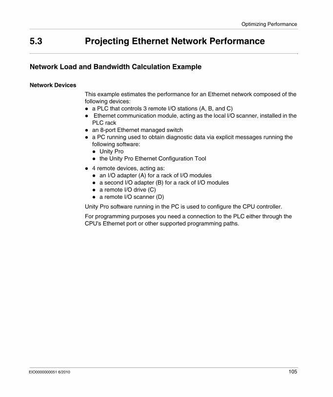
Optimizing Performance
5.3 Projecting Ethernet Network Performance
Network Load and Bandwidth Calculation Example
Network Devices
This example estimates the performance for an Ethernet network composed of the following devices:
a PLC that controls 3 remote I/O stations (A, B, and C) Ethernet communication module, acting as the local I/O scanner, installed in the PLC rackan 8-port Ethernet managed switcha PC running used to obtain diagnostic data via explicit messages running the following software:
Unity Prothe Unity Pro Ethernet Configuration Tool
4 remote devices, acting as:an I/O adapter (A) for a rack of I/O modulesa second I/O adapter (B) for a rack of I/O modulesa remote I/O drive (C)a remote I/O scanner (D)
Unity Pro software running in the PC is used to configure the CPU controller.
For programming purposes you need a connection to the PLC either through the CPU's Ethernet port or other supported programming paths.
EIO0000000051 6/2010 105
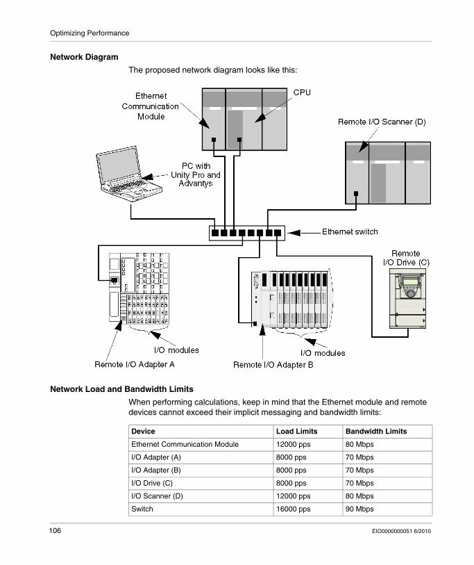
Optimizing Performance
Network Diagram
The proposed network diagram looks like this:
Network Load and Bandwidth Limits
When performing calculations, keep in mind that the Ethernet module and remote devices cannot exceed their implicit messaging and bandwidth limits:
Device Load Limits Bandwidth Limits
Ethernet Communication Module 12000 pps 80 Mbps
I/O Adapter (A) 8000 pps 70 Mbps
I/O Adapter (B) 8000 pps 70 Mbps
I/O Drive (C) 8000 pps 70 Mbps
I/O Scanner (D) 12000 pps 80 Mbps
Switch 16000 pps 90 Mbps
106 EIO0000000051 6/2010
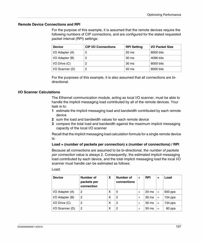
Optimizing Performance
Remote Device Connections and RPI
For the purpose of this example, it is assumed that the remote devices require the following numbers of CIP connections, and are configured for the stated requested packet interval (RPI) settings:
For the purposes of this example, it is also assumed that all connections are bi-directional.
I/O Scanner Calculations
The Ethernet communication module, acting as local I/O scanner, must be able to handle the implicit messaging load contributed by all of the remote devices. Your task is to:1 estimate the implicit messaging load and bandwidth contributed by each remote
device2 sum the load and bandwidth values for each remote device3 compare the total load and bandwidth against the maximum implicit messaging
capacity of the local I/O scanner
Recall that the implicit messaging load calculation formula for a single remote device is:
Load = (number of packets per connection) x (number of connections) / RPI
Because all connections are assumed to be bi-directional, the number of packets per connection value is always 2. Consequently, the estimated implicit messaging load contributed by each device, and the total implicit messaging load the local I/O scanner must handle can be estimated as follows:
Load:
Device CIP I/O Connections RPI Setting I/O Packet Size
I/O Adapter (A) 5 20 ms 8000 bits
I/O Adapter (B) 2 30 ms 4096 bits
I/O Drive (C) 2 30 ms 8000 bits
I/O Scanner (D) 2 50 ms 8000 bits
Device Number of packets per connection
X Number of connections
÷ RPI = Load
I/O Adapter (A) 2 X 5 ÷ 20 ms = 500 pps
I/O Adapter (B) 2 X 2 ÷ 30 ms = 134 pps
I/O Drive (C) 2 X 2 ÷ 30 ms = 134 pps
I/O Scanner (D) 2 X 2 ÷ 50 ms = 80 pps
EIO0000000051 6/2010 107
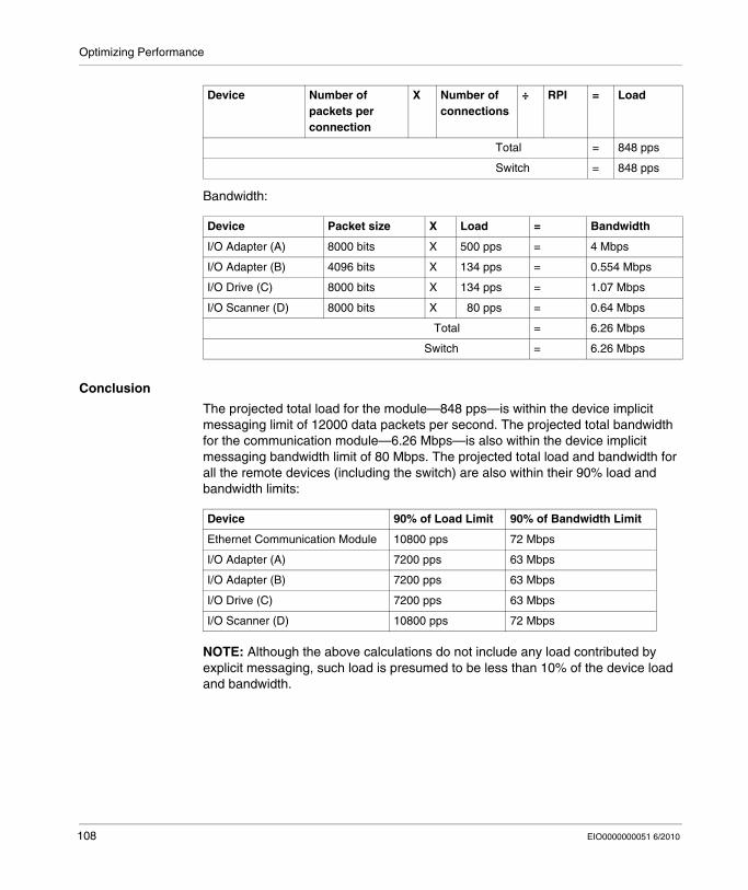
Optimizing Performance
Bandwidth:
Conclusion
The projected total load for the module—848 pps—is within the device implicit messaging limit of 12000 data packets per second. The projected total bandwidth for the communication module—6.26 Mbps—is also within the device implicit messaging bandwidth limit of 80 Mbps. The projected total load and bandwidth for all the remote devices (including the switch) are also within their 90% load and bandwidth limits:
NOTE: Although the above calculations do not include any load contributed by explicit messaging, such load is presumed to be less than 10% of the device load and bandwidth.
Total = 848 pps
Switch = 848 pps
Device Packet size X Load = Bandwidth
I/O Adapter (A) 8000 bits X 500 pps = 4 Mbps
I/O Adapter (B) 4096 bits X 134 pps = 0.554 Mbps
I/O Drive (C) 8000 bits X 134 pps = 1.07 Mbps
I/O Scanner (D) 8000 bits X 80 pps = 0.64 Mbps
Total = 6.26 Mbps
Switch = 6.26 Mbps
Device Number of packets per connection
X Number of connections
÷ RPI = Load
Device 90% of Load Limit 90% of Bandwidth Limit
Ethernet Communication Module 10800 pps 72 Mbps
I/O Adapter (A) 7200 pps 63 Mbps
I/O Adapter (B) 7200 pps 63 Mbps
I/O Drive (C) 7200 pps 63 Mbps
I/O Scanner (D) 10800 pps 72 Mbps
108 EIO0000000051 6/2010
EIO0000000051 6/2010
6
Replacing the STB NIP 2311 NIM
EIO0000000051 6/2010
Replacing the STB NIP 2311 NIM
Replacing the STB NIP 2311 Module
Introduction
The device replacement procedure anticipates the simple replacement of a NIM on an Ethernet network with another with the same part number (STB NIP 2311). Both NIMs must have the same firmware version and you must configure the replacement NIM with the same settings as the original. When the NIM configuration is saved to the removable memory card (see page 53), you can replace the NIM and use the same configuration simply by reinserting the card in the new NIM.
Replacement Process
Replace an STB NIP 2311 module with another containing the same version firmware:
Stage Description
1 Save your customized island configuration to a removable memory card, as described below.NOTE: We recommend that you save customized island configurations to a removable memory card whenever you edit the configuration. If you have to replace the STB NIP 2311 NIM before you have copied the island configuration to the card, the STB NIP 2311 may not be operational (and the island configuration settings may not be accessible) when you switch from one NIM to another.
2 Remove the existing STB NIP 2311 NIM.
3 Install a replacement STB NIP 2311 module into the island.
4 Insert the memory card in the replacement NIM.
109
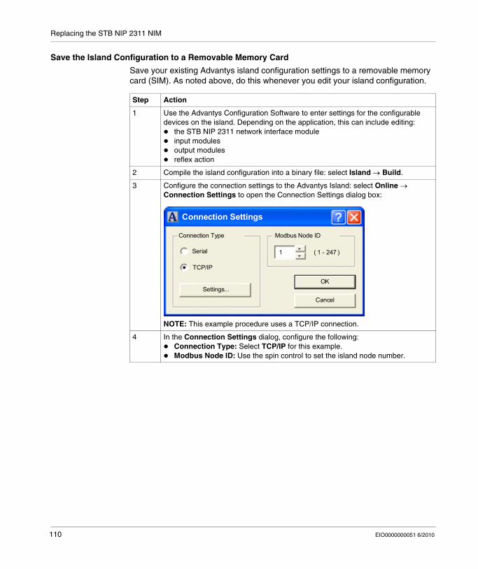
Replacing the STB NIP 2311 NIM
Save the Island Configuration to a Removable Memory Card
Save your existing Advantys island configuration settings to a removable memory card (SIM). As noted above, do this whenever you edit your island configuration.
Step Action
1 Use the Advantys Configuration Software to enter settings for the configurable devices on the island. Depending on the application, this can include editing:
the STB NIP 2311 network interface moduleinput modulesoutput modulesreflex action
2 Compile the island configuration into a binary file: select Island → Build.
3 Configure the connection settings to the Advantys Island: select Online → Connection Settings to open the Connection Settings dialog box:
NOTE: This example procedure uses a TCP/IP connection.
4 In the Connection Settings dialog, configure the following:Connection Type: Select TCP/IP for this example.Modbus Node ID: Use the spin control to set the island node number.
Connection Settings
Connection Type
Serial
TCP/IP
Modbus Node ID
Settings...OK
Cancel
( 1 - 247 )1
110 EIO0000000051 6/2010
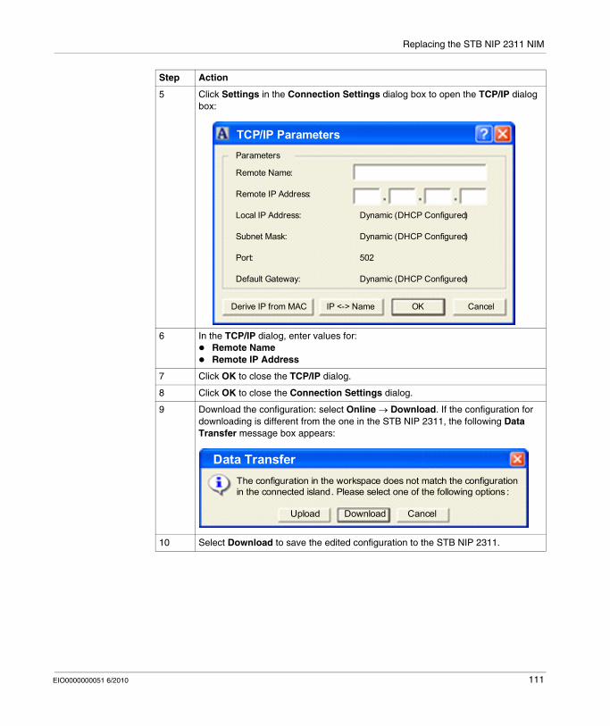
Replacing the STB NIP 2311 NIM
5 Click Settings in the Connection Settings dialog box to open the TCP/IP dialog box:
6 In the TCP/IP dialog, enter values for:Remote NameRemote IP Address
7 Click OK to close the TCP/IP dialog.
8 Click OK to close the Connection Settings dialog.
9 Download the configuration: select Online → Download. If the configuration for downloading is different from the one in the STB NIP 2311, the following Data Transfer message box appears:
10 Select Download to save the edited configuration to the STB NIP 2311.
Step Action
TCP/IP Parameters
OK Cancel
Parameters
Remote Name:
Remote IP Address:
Local IP Address:
Subnet Mask:
Port:
Default Gateway:
Dynamic (DHCP Configured)
502
Dynamic (DHCP Configured)
Dynamic (DHCP Configured)
Derive IP from MAC IP <-> Name
Cancel
Data Transfer
Upload Download
The configuration in the workspace does not match the configuration in the connected island. Please select one of the following options :
EIO0000000051 6/2010 111
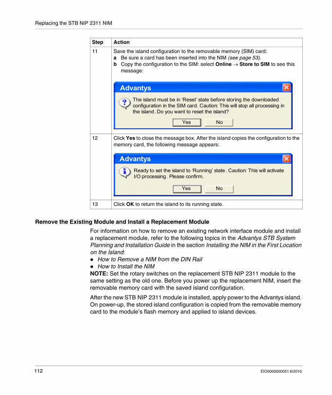
Replacing the STB NIP 2311 NIM
Remove the Existing Module and Install a Replacement Module
For information on how to remove an existing network interface module and install a replacement module, refer to the following topics in the Advantys STB System Planning and Installation Guide in the section Installing the NIM in the First Location on the Island:
How to Remove a NIM from the DIN RailHow to Install the NIM
NOTE: Set the rotary switches on the replacement STB NIP 2311 module to the same setting as the old one. Before you power up the replacement NIM, insert the removable memory card with the saved island configuration.
After the new STB NIP 2311 module is installed, apply power to the Advantys island. On power-up, the stored island configuration is copied from the removable memory card to the module’s flash memory and applied to island devices.
11 Save the island configuration to the removable memory (SIM) card:a Be sure a card has been inserted into the NIM (see page 53).b Copy the configuration to the SIM: select Online → Store to SIM to see this
message:
12 Click Yes to close the message box. After the island copies the configuration to the memory card, the following message appears:
13 Click OK to return the island to its running state.
Step Action
No
Advantys
Yes
The island must be in ‘Reset’ state before storing the downloaded configuration in the SIM card. Caution: This will stop all processing in the island. Do you want to reset the island?
No
Advantys
Yes
Ready to set the island to ‘Running’ state. Caution: This will activate I/O processing. Please confirm.
112 EIO0000000051 6/2010
EIO0000000051 6/2010
7
STB NIP 2311 Services
EIO0000000051 6/2010
STB NIP 2311 Services
Introduction
This chapter describes the services provided by the STB NIP 2311 network interface module.
What's in this Chapter?
This chapter contains the following sections:
Section Topic Page
7.1 Modbus Messaging 114
7.2 Server-Assigned IP Parameters 142
7.3 Embedded Web Pages 143
7.4 SNMP Services 179
113
STB NIP 2311 Services
7.1 Modbus Messaging
Introduction
The STB NIP 2311 implements the Modbus Messaging server service. This section describes how data stored in the process image is exchanged between the STB NIP 2311 and the Ethernet network, via Modbus over TCP/IP.
What's in this Section?
This section contains the following topics:
Topic Page
Modbus Messaging Service Description 115
Data Exchange with the STB NIP 2311 120
Reading Diagnostic Data 129
Modbus Commands Supported by the STB NIP 2311 NIM 137
Modbus Exception Responses 141
114 EIO0000000051 6/2010
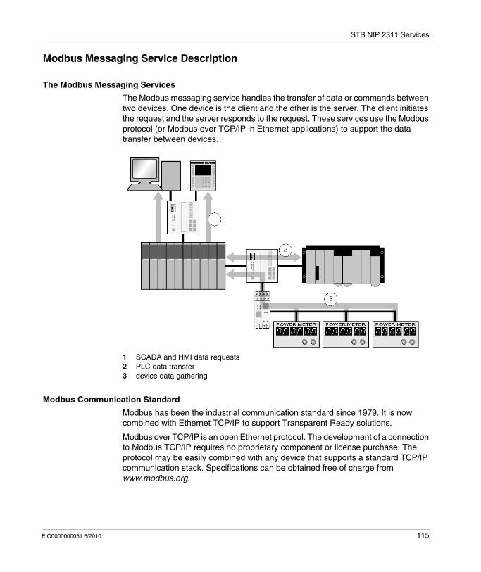
STB NIP 2311 Services
Modbus Messaging Service Description
The Modbus Messaging Services
The Modbus messaging service handles the transfer of data or commands between two devices. One device is the client and the other is the server. The client initiates the request and the server responds to the request. These services use the Modbus protocol (or Modbus over TCP/IP in Ethernet applications) to support the data transfer between devices.
1 SCADA and HMI data requests2 PLC data transfer3 device data gathering
Modbus Communication Standard
Modbus has been the industrial communication standard since 1979. It is now combined with Ethernet TCP/IP to support Transparent Ready solutions.
Modbus over TCP/IP is an open Ethernet protocol. The development of a connection to Modbus TCP/IP requires no proprietary component or license purchase. The protocol may be easily combined with any device that supports a standard TCP/IP communication stack. Specifications can be obtained free of charge from www.modbus.org.
EIO0000000051 6/2010 115
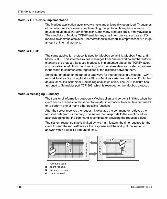
STB NIP 2311 Services
Modbus TCP Device Implementation
The Modbus application layer is very simple and universally recognized. Thousands of manufacturers are already implementing this protocol. Many have already developed Modbus TCP/IP connections, and many products are currently available. The simplicity of Modbus TCP/IP enables any small field device, such as an I/O module, to communicate over Ethernet without a powerful microprocessor or a large amount of internal memory.
Modbus TCP/IP
The same application protocol is used for Modbus serial link, Modbus Plus, and Modbus TCP. This interface routes messages from one network to another without changing the protocol. Because Modbus is implemented above the TCP/IP layer, you can also benefit from the IP routing, which enables devices located anywhere in the world to communicate regardless of the distance between them.
Schneider offers an entire range of gateways for interconnecting a Modbus TCP/IP network to already existing Modbus Plus or Modbus serial link networks. For further details, consult a Schneider Electric regional sales office. The IANA institute has assigned to Schneider port TCP 502, which is reserved for the Modbus protocol.
Modbus Messaging Summary
The transfer of information between a Modbus client and server is initiated when the client sends a request to the server to transfer information, to execute a command, or to perform one of many other possible functions.
After the server receives the request, it executes the command or retrieves the required data from its memory. The server then responds to the client by either acknowledging that the command is complete or providing the requested data.
The system response time is limited by two main factors, the time required for the client to send the request/receive the response and the ability of the server to answer within a specific amount of time.
1 retrieved data2 client request3 server response4 data retrieval
116 EIO0000000051 6/2010
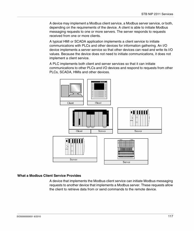
STB NIP 2311 Services
A device may implement a Modbus client service, a Modbus server service, or both, depending on the requirements of the device. A client is able to initiate Modbus messaging requests to one or more servers. The server responds to requests received from one or more clients.
A typical HMI or SCADA application implements a client service to initiate communications with PLCs and other devices for information gathering. An I/O device implements a server service so that other devices can read and write its I/O values. Because the device does not need to initiate communications, it does not implement a client service.
A PLC implements both client and server services so that it can initiate communications to other PLCs and I/O devices and respond to requests from other PLCs, SCADA, HMIs and other devices.
What a Modbus Client Service Provides
A device that implements the Modbus client service can initiate Modbus messaging requests to another device that implements a Modbus server. These requests allow the client to retrieve data from or send commands to the remote device.
EIO0000000051 6/2010 117
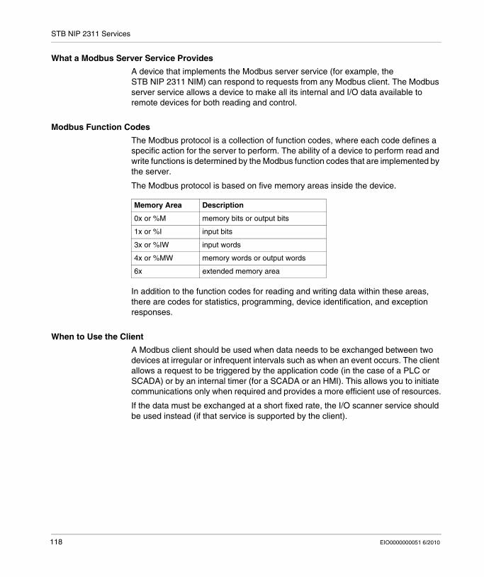
STB NIP 2311 Services
What a Modbus Server Service Provides
A device that implements the Modbus server service (for example, the STB NIP 2311 NIM) can respond to requests from any Modbus client. The Modbus server service allows a device to make all its internal and I/O data available to remote devices for both reading and control.
Modbus Function Codes
The Modbus protocol is a collection of function codes, where each code defines a specific action for the server to perform. The ability of a device to perform read and write functions is determined by the Modbus function codes that are implemented by the server.
The Modbus protocol is based on five memory areas inside the device.
In addition to the function codes for reading and writing data within these areas, there are codes for statistics, programming, device identification, and exception responses.
When to Use the Client
A Modbus client should be used when data needs to be exchanged between two devices at irregular or infrequent intervals such as when an event occurs. The client allows a request to be triggered by the application code (in the case of a PLC or SCADA) or by an internal timer (for a SCADA or an HMI). This allows you to initiate communications only when required and provides a more efficient use of resources.
If the data must be exchanged at a short fixed rate, the I/O scanner service should be used instead (if that service is supported by the client).
Memory Area Description
0x or %M memory bits or output bits
1x or %I input bits
3x or %IW input words
4x or %MW memory words or output words
6x extended memory area
118 EIO0000000051 6/2010

STB NIP 2311 Services
When to Use the Server
The Modbus server is accessed by either a Modbus client or an I/O scanner service and should be used to transfer plant information, commands, or other required data. The Modbus server provides real-time data transfer or access to data reports that are stored in its memory. The Modbus server answers any Modbus requests it receives. No additional configuration is necessary.
Any device that needs to exchange plant status, commands or data with other devices should implement a Modbus server. A device that implements the server can respond to requests sent from Modbus clients and make its internal I/O and data available to remote devices for reading and control. The device may be an I/O module, a drive, a power meter, a circuit breaker, a motor starter, or a PLC.
I/O modules are good examples of devices that implement a Modbus server service. As servers, input modules let other control devices read values from them, and output modules let control devices write values to them.
A PLC system implements both client and server services. The client service enables the PLC to communicate with other PLCs and I/O modules; the server service enables it to respond to requests from other PLCs, SCADA, HMIs and other devices. Devices that do not need to respond to data transfer requests should not need to implement a server service.
EIO0000000051 6/2010 119
STB NIP 2311 Services
Data Exchange with the STB NIP 2311
Introduction
Data exchange between a Modbus over TCP/IP host or the HTTP embedded web server and the Advantys STB island bus is conducted over the Ethernet port on the STB NIP 2311 module.
Master Devices
The input and output data image areas (see page 241) can be accessed and monitored over the Ethernet LAN by a Modbus over TCP/IP fieldbus master or the STB NIP 2311 HTTP embedded web server.
The Ethernet port on the STB NIP 2311 is configured as follows:
Port 502 SAP: Modbus over TCP/IPPort 80 SAP: HTTPPort 161 SAP: SNMP
NOTE: An HMI panel or a device running the Advantys Configuration Software can also exchange data with an island through the STB NIP 2311’s CFG port (see page 33).
Modbus over TCP/IP Communications
Master devices use Modbus messaging to read and write data to specific registers in the process image. The Modbus protocol is understood regardless of the network type.
The Modbus protocol uses a 16-bit word data format.
Data Exchange Process
Data stored in the process image is exchanged between the STB NIP 2311 module and the Ethernet network through Modbus over TCP/IP. First, data from the Ethernet host is written to the output data image area (see page 122) in the NIM’s process image. Then, status, echo output, and input data information from the I/O modules on the island are placed in the input data image area (see page 124). The Modbus master can access that data through the TCP/IP network or the CFG port.
Data in the output and the input areas of the process image is organized in the order that the I/O modules are assembled on the island bus (see page 121).
120 EIO0000000051 6/2010
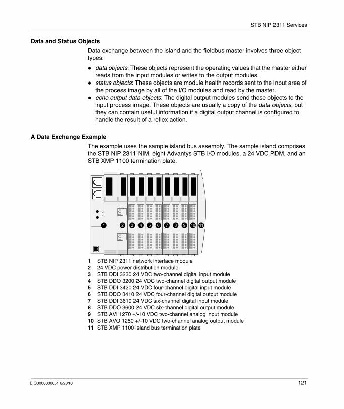
STB NIP 2311 Services
Data and Status Objects
Data exchange between the island and the fieldbus master involves three object types:
data objects: These objects represent the operating values that the master either reads from the input modules or writes to the output modules.status objects: These objects are module health records sent to the input area of the process image by all of the I/O modules and read by the master.echo output data objects: The digital output modules send these objects to the input process image. These objects are usually a copy of the data objects, but they can contain useful information if a digital output channel is configured to handle the result of a reflex action.
A Data Exchange Example
The example uses the sample island bus assembly. The sample island comprises the STB NIP 2311 NIM, eight Advantys STB I/O modules, a 24 VDC PDM, and an STB XMP 1100 termination plate:
1 STB NIP 2311 network interface module2 24 VDC power distribution module3 STB DDI 3230 24 VDC two-channel digital input module4 STB DDO 3200 24 VDC two-channel digital output module5 STB DDI 3420 24 VDC four-channel digital input module6 STB DDO 3410 24 VDC four-channel digital output module7 STB DDI 3610 24 VDC six-channel digital input module8 STB DDO 3600 24 VDC six-channel digital output module9 STB AVI 1270 +/-10 VDC two-channel analog input module10 STB AVO 1250 +/-10 VDC two-channel analog output module11 STB XMP 1100 island bus termination plate
1 2 3 5 116 74 8 9 10
EIO0000000051 6/2010 121

STB NIP 2311 Services
The I/O modules have the following island bus addresses:
The PDM and the termination plate are not addressable (see page 44), so they exchange neither data objects nor status objects with the fieldbus master.
The Output Data Process Image
The output data process image contains the data written to the island from the Modbus over TCP/IP host. This data is used to update the output modules on the island bus. In the sample island bus assembly, there are four output modules (three digital output modules and one analog output module).
I/O Model Module Type Module’s Island Bus Address
STB DDI 3230 2-channel digital input 1
STB DDO 3200 2-channel digital output 2
STB DDI 3420 4-channel digital input 3
STB DDO 3410 4-channel digital output 4
STB DDI 3610 6-channel digital input 5
STB DDO 3600 6-channel digital output 6
STB AVI 1270 2-channel analog input 7
STB AVO 1250 2-channel analog output 8
122 EIO0000000051 6/2010
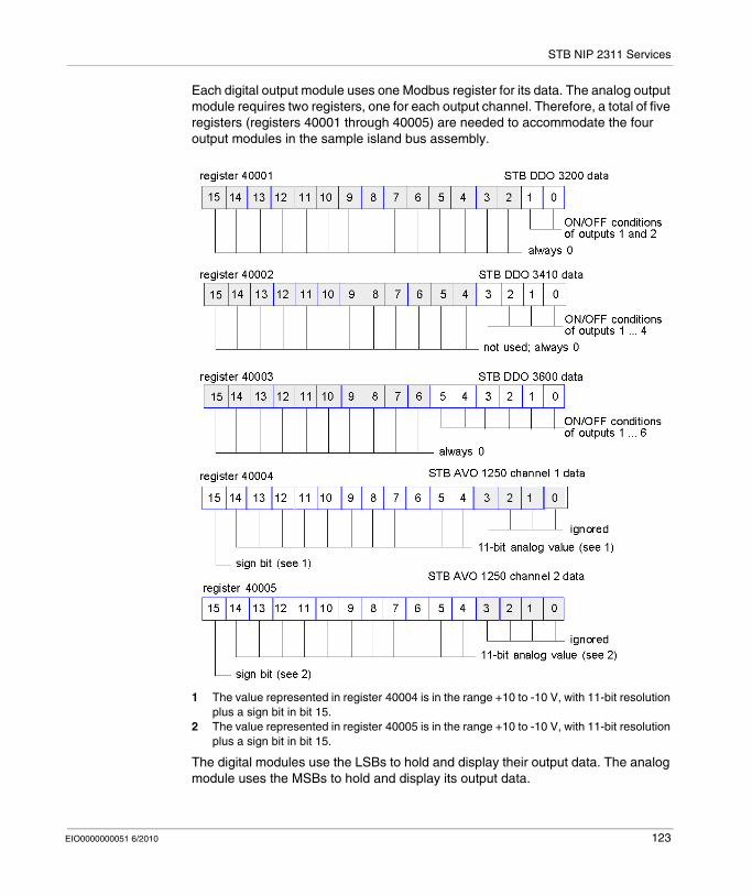
STB NIP 2311 Services
Each digital output module uses one Modbus register for its data. The analog output module requires two registers, one for each output channel. Therefore, a total of five registers (registers 40001 through 40005) are needed to accommodate the four output modules in the sample island bus assembly.
1 The value represented in register 40004 is in the range +10 to -10 V, with 11-bit resolution plus a sign bit in bit 15.
2 The value represented in register 40005 is in the range +10 to -10 V, with 11-bit resolution plus a sign bit in bit 15.
The digital modules use the LSBs to hold and display their output data. The analog module uses the MSBs to hold and display its output data.
EIO0000000051 6/2010 123
STB NIP 2311 Services
The Input Data and I/O Status Process Image
Input data and I/O status information from the I/O modules are sent to the input process image area. The fieldbus master or another monitoring device (for example, an HMI panel (see page 243)) can view data in the input data image area.
All eight I/O modules are represented in the input process image area. Their assigned registers start at 45392 and continue in the order of their island bus addresses.
A digital I/O module uses two contiguous registers:
Digital input modules use one register to report data and the next to report status.Digital output modules use one register to report echo output data and the next to report status.
NOTE: The value in an echo output data register is basically a copy of the value written to the corresponding register in the output data process image area (see page 122). Generally, the fieldbus master writes this value to the NIM, and the echo is of not much interest. If an output channel is configured to perform a reflex action (see page 230), however, the echo register provides a location where the fieldbus master can view the current value of the output.
The analog input module uses four contiguous registers:
The first register reports the data for channel 1.The second register reports the status for channel 1.The third register reports the data for channel 2.The fourth register reports the status for channel 2.
The analog output module uses two contiguous registers:The first register reports the status for channel 1.The second register reports the status for channel 2.
124 EIO0000000051 6/2010
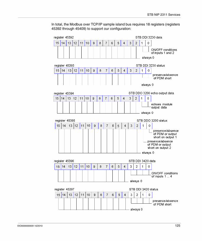
STB NIP 2311 Services
In total, the Modbus over TCP/IP sample island bus requires 18 registers (registers 45392 through 45409) to support our configuration:
EIO0000000051 6/2010 125
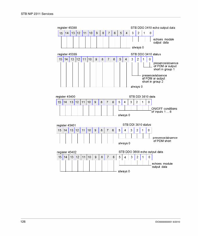
STB NIP 2311 Services
126 EIO0000000051 6/2010
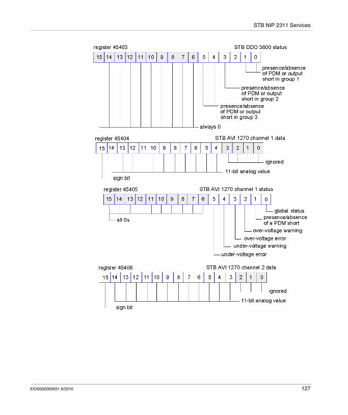
STB NIP 2311 Services
EIO0000000051 6/2010 127
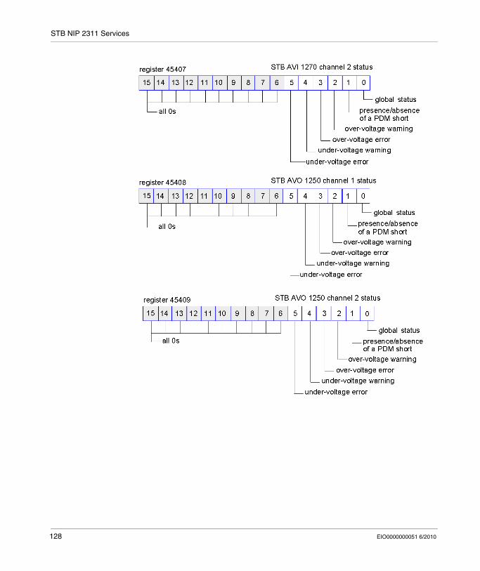
STB NIP 2311 Services
128 EIO0000000051 6/2010
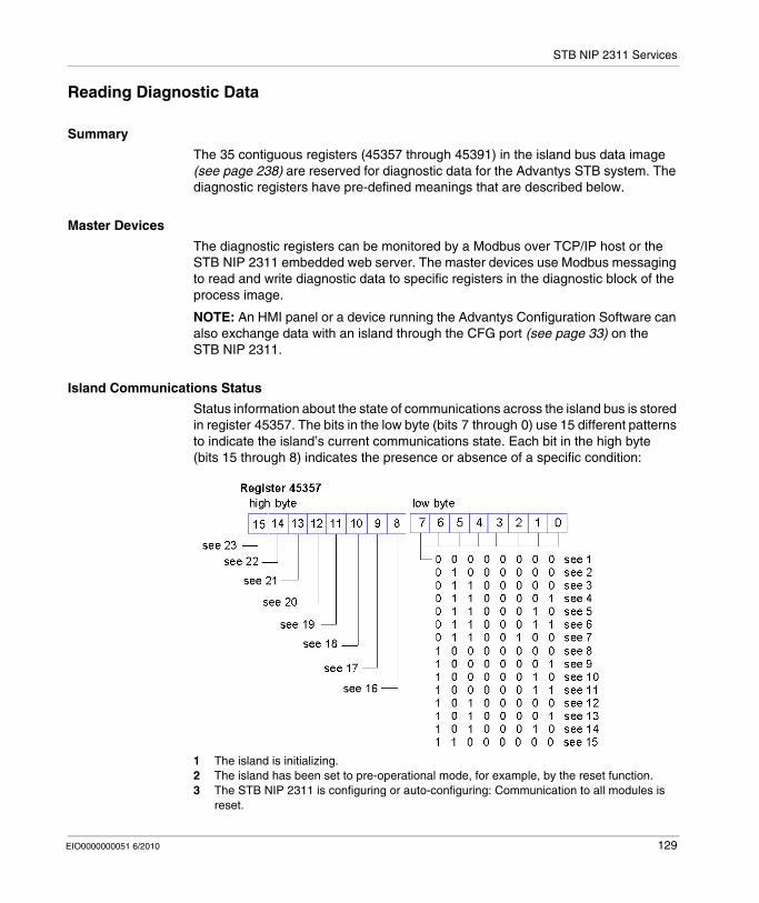
STB NIP 2311 Services
Reading Diagnostic Data
Summary
The 35 contiguous registers (45357 through 45391) in the island bus data image (see page 238) are reserved for diagnostic data for the Advantys STB system. The diagnostic registers have pre-defined meanings that are described below.
Master Devices
The diagnostic registers can be monitored by a Modbus over TCP/IP host or the STB NIP 2311 embedded web server. The master devices use Modbus messaging to read and write diagnostic data to specific registers in the diagnostic block of the process image.
NOTE: An HMI panel or a device running the Advantys Configuration Software can also exchange data with an island through the CFG port (see page 33) on the STB NIP 2311.
Island Communications Status
Status information about the state of communications across the island bus is stored in register 45357. The bits in the low byte (bits 7 through 0) use 15 different patterns to indicate the island’s current communications state. Each bit in the high byte (bits 15 through 8) indicates the presence or absence of a specific condition:
1 The island is initializing.2 The island has been set to pre-operational mode, for example, by the reset function.3 The STB NIP 2311 is configuring or auto-configuring: Communication to all modules is
reset.
EIO0000000051 6/2010 129

STB NIP 2311 Services
4 The STB NIP 2311 is configuring or auto-configuring: The NIM checks for any modules that are not auto-addressed.
5 The STB NIP 2311 is configuring or auto-configuring. Advantys STB and preferred modules are being auto-addressed.
6 The STB NIP 2311 is configuring or auto-configuring. Boot-up is in progress.7 The process image is being set up.8 Initialization is complete, the island bus is configured, the configuration matches, and the
island bus is not started.9 Configuration mismatch: Non-mandatory or unexpected modules in the configuration do
not match, and the island bus is not started.10 Configuration mismatch: At least 1 mandatory module does not match, and the island bus
is not started.11 Serious configuration mismatch: the island bus has been set to pre-operational mode, and
initialization is aborted.12 The configuration matches, and the island bus is operational.13 The island is operational with a configuration mismatch. At least 1 standard module does
not match, but all the mandatory modules are present and operating.14 Serious configuration mismatch: The island bus was started but is now in pre-operational
mode because of 1 or more mismatched mandatory module(s).15 The island has been set to pre-operational mode, for example, by the stop function.16 A value of 1 in bit 8 indicates a low-priority receive queue software overrun. (See note
below.)17 A value of 1 in bit 9 indicates a NIM overrun. 18 A value of 1 in bit 10 indicates that the island bus is off. (See note below.)19 A value of 1 in bit 11 indicates that NIM has reached the alert level and the event status bit
has been set.20 A value of 1 in bit 12 indicates that the NIM’s event status bit has been reset. (See note
below.)21 A value of 1 in bit 13 indicates a low-priority transmit queue software overrun. (See note
below.)22 A value of 1 in bit 14 indicates a high-priority receive queue software overrun. (See note
below.)23 A value of 1 in bit 15 indicates a high-priority transmit queue software overrun. (See note
below.)
NOTE: Conditions described in 16, 20, 21, 22, and 23 make the NIM inoperable.
Internal NIM events, events in the island configuration, or events in the software can stop the island bus. To get out of this state:
Step Action
1 Cycle the power.
2 Reset the island from the Advantys Configuration Software.
3 Clear the status bits with the Advantys Configuration Software.
130 EIO0000000051 6/2010
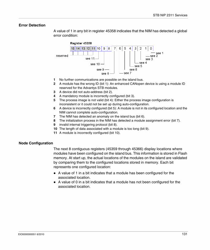
STB NIP 2311 Services
Error Detection
A value of 1 in any bit in register 45358 indicates that the NIM has detected a global error condition:
1 No further communications are possible on the island bus.2 A module has the wrong ID (bit 1): An enhanced CANopen device is using a module ID
reserved for the Advantys STB modules.3 A device did not auto-address (bit 2).4 A mandatory module is incorrectly configured (bit 3).5 The process image is not valid (bit 4): Either the process image configuration is
inconsistent or it could not be set up during auto-configuration.6 A device is incorrectly configured (bit 5): A module is not in its configured location and the
NIM cannot complete auto-configuration.7 The NIM has detected an anomaly on the island bus (bit 6).8 The initialization process in the NIM has detected a module assignment error (bit 7).9 invalid internal triggering protocol (bit 8).10 The length of data associated with a module is too long (bit 9).11 A module is incorrectly configured (bit 10).
Node Configuration
The next 8 contiguous registers (45359 through 45366) display locations where modules have been configured on the island bus. This information is stored in Flash memory. At start up, the actual locations of the modules on the island are validated by comparing them to the configured locations stored in memory. Each bit represents one configured location:
A value of 1 in a bit indicates that a module has been configured for the associated location.A value of 0 in a bit indicates that a module has not been configured for the associated location.
EIO0000000051 6/2010 131
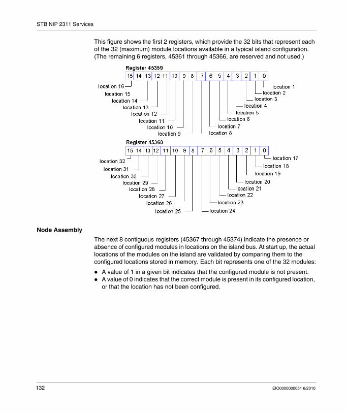
STB NIP 2311 Services
This figure shows the first 2 registers, which provide the 32 bits that represent each of the 32 (maximum) module locations available in a typical island configuration. (The remaining 6 registers, 45361 through 45366, are reserved and not used.)
Node Assembly
The next 8 contiguous registers (45367 through 45374) indicate the presence or absence of configured modules in locations on the island bus. At start up, the actual locations of the modules on the island are validated by comparing them to the configured locations stored in memory. Each bit represents one of the 32 modules:
A value of 1 in a given bit indicates that the configured module is not present.A value of 0 indicates that the correct module is present in its configured location, or that the location has not been configured.
132 EIO0000000051 6/2010
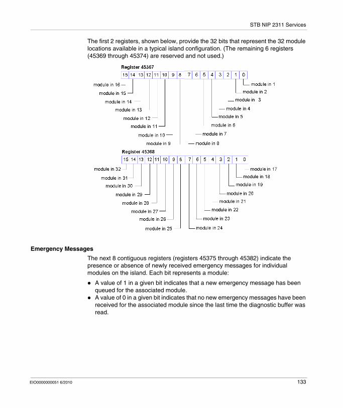
STB NIP 2311 Services
The first 2 registers, shown below, provide the 32 bits that represent the 32 module locations available in a typical island configuration. (The remaining 6 registers (45369 through 45374) are reserved and not used.)
Emergency Messages
The next 8 contiguous registers (registers 45375 through 45382) indicate the presence or absence of newly received emergency messages for individual modules on the island. Each bit represents a module:
A value of 1 in a given bit indicates that a new emergency message has been queued for the associated module.A value of 0 in a given bit indicates that no new emergency messages have been received for the associated module since the last time the diagnostic buffer was read.
EIO0000000051 6/2010 133
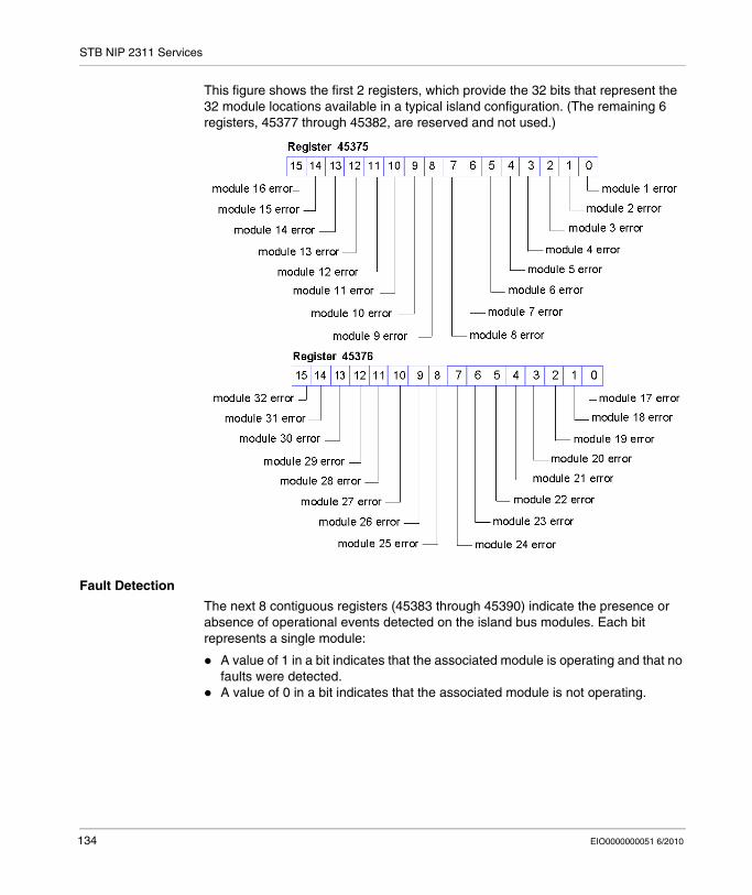
STB NIP 2311 Services
This figure shows the first 2 registers, which provide the 32 bits that represent the 32 module locations available in a typical island configuration. (The remaining 6 registers, 45377 through 45382, are reserved and not used.)
Fault Detection
The next 8 contiguous registers (45383 through 45390) indicate the presence or absence of operational events detected on the island bus modules. Each bit represents a single module:
A value of 1 in a bit indicates that the associated module is operating and that no faults were detected.A value of 0 in a bit indicates that the associated module is not operating.
134 EIO0000000051 6/2010
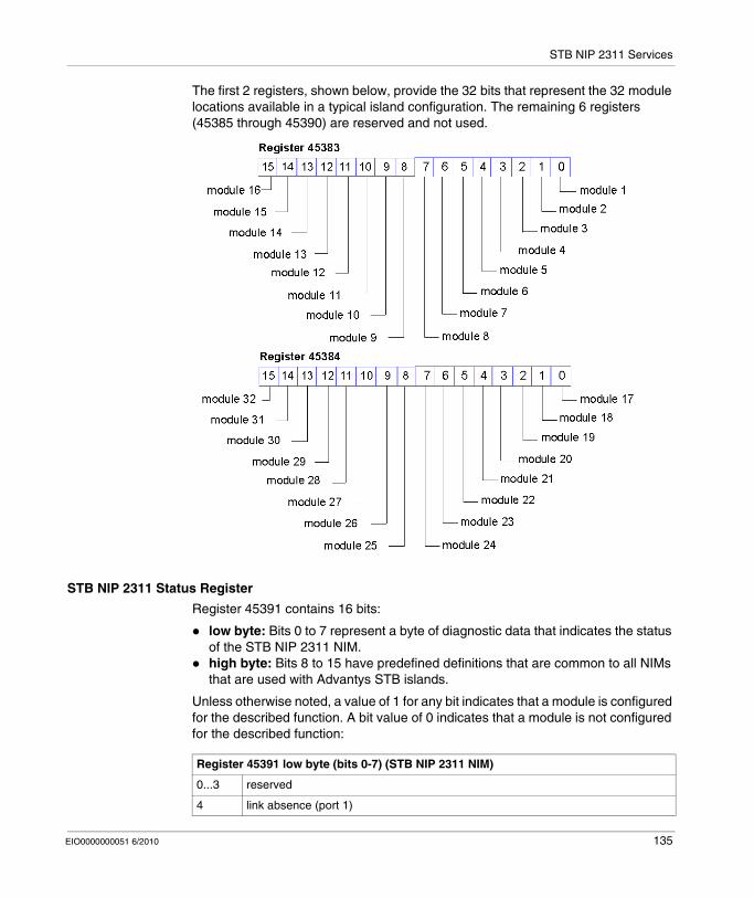
STB NIP 2311 Services
The first 2 registers, shown below, provide the 32 bits that represent the 32 module locations available in a typical island configuration. The remaining 6 registers (45385 through 45390) are reserved and not used.
STB NIP 2311 Status Register
Register 45391 contains 16 bits:
low byte: Bits 0 to 7 represent a byte of diagnostic data that indicates the status of the STB NIP 2311 NIM.high byte: Bits 8 to 15 have predefined definitions that are common to all NIMs that are used with Advantys STB islands.
Unless otherwise noted, a value of 1 for any bit indicates that a module is configured for the described function. A bit value of 0 indicates that a module is not configured for the described function:
Register 45391 low byte (bits 0-7) (STB NIP 2311 NIM)
0...3 reserved
4 link absence (port 1)
EIO0000000051 6/2010 135
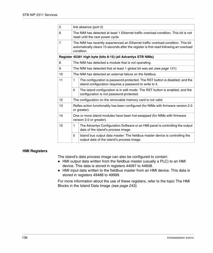
STB NIP 2311 Services
HMI Registers
The island’s data process image can also be configured to contain:HMI output data written from the fieldbus master (usually a PLC) to an HMI device. This data is stored in registers 44097 to 44608.HMI input data written to the fieldbus master from an HMI device. This data is stored in registers 49488 to 49999.
For more information about the use of these registers, refer to the topic The HMI Blocks in the Island Data Image (see page 243).
5 link absence (port 2)
6 The NIM has detected at least 1 Ethernet traffic overload condition. This bit is not reset until the next power cycle.
7 The NIM has recently experienced an Ethernet traffic overload condition. This bit automatically clears 15 seconds after the register is first read following an overload condition.
Register 45391 high byte (bits 8-15) (all Advantys STB NIMs)
8 The NIM has detected a module that is not operating.
9 The NIM has detected that at least 1 global bit was set (see page 131).
10 The NIM has detected an external failure on the fieldbus.
11 1 The configuration is password-protected. The RST button is disabled, and the island configuration requires a password to write to it.
0 The island configuration is in edit mode. The RST button is enabled, and the configuration is not password-protected.
12 The configuration on the removable memory card is not valid.
13 Reflex action functionality has been configured (for NIMs with firmware version 2.0 or greater).
14 One or more island modules have been hot-swapped (for NIMs with firmware version 2.0 or greater).
15 1 The Advantys Configuration Software or an HMI panel is controlling the output data of the island’s process image.
0 Island bus output data master: The fieldbus master device is controlling the output data of the island’s process image.
136 EIO0000000051 6/2010
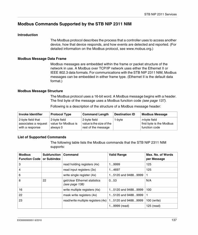
STB NIP 2311 Services
Modbus Commands Supported by the STB NIP 2311 NIM
Introduction
The Modbus protocol describes the process that a controller uses to access another device, how that device responds, and how events are detected and reported. (For detailed information on the Modbus protocol, see www.mobus.org.)
Modbus Message Data Frame
Modbus messages are embedded within the frame or packet structure of the network in use. A Modbus over TCP/IP network uses either the Ethernet II or IEEE 802.3 data formats. For communications with the STB NIP 2311 NIM, Modbus messages can be embedded in either frame type. (Ethernet II is the default data format.)
Modbus Message Structure
The Modbus protocol uses a 16-bit word. A Modbus message begins with a header. The first byte of the message uses a Modbus function code (see page 137).
Following is a description of the structure of a Modbus message header:
List of Supported Commands
The following table lists the Modbus commands that the STB NIP 2311 NIM supports:
Invoke Identifier Protocol Type Command Length Destination ID Modbus Message
2-byte field that associates a request with a response
2-byte fieldvalue for Modbus is always 0
2-byte fieldvalue is the size of the rest of the message
1-byte n-byte fieldfirst byte is the Modbus function code
Modbus Function Code
Subfunction or Subindex
Command Valid Range Max. No. of Words per Message
3 read holding registers (4x) 1...9999 125
4 read input registers (3x) 1...4697 125
6 write single register (4x) 1...5120 and 9488...9999 1
8 22 get/clear Ethernet statistics (see page 138)
0...53 N/A
16 write multiple registers (4x) 1...5120 and 9488...9999 100
22 mask write registers (4x) 1...5120 and 9488...9999 1
23 read/write multiple registers (4x) 1...5120 and 9488...9999 100 (write)
1...9999 (read) 125 (read)
EIO0000000051 6/2010 137
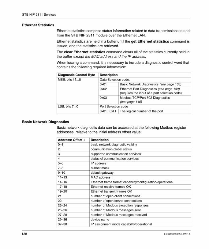
STB NIP 2311 Services
Ethernet Statistics
Ethernet statistics comprise status information related to data transmissions to and from the STB NIP 2311 module over the Ethernet LAN.
Ethernet statistics are held in a buffer until the get Ethernet statistics command is issued, and the statistics are retrieved.
The clear Ethernet statistics command clears all of the statistics currently held in the buffer except the MAC address and the IP address.
When issuing a command, it is necessary to include a diagnostic control word that contains the following required information:
Basic Network Diagnostics
Basic network diagnostic data can be accessed at the following Modbus register addresses, relative to the initial address offset value:
Diagnostic Control Byte DescriptionMSB: bits 15...8 Data Selection code:
0x01 Basic Network Diagnostics (see page 138)0x02 Ethernet Port Diagnostics (see page 139)
(requires the input of a port selection code)0x03 Modbus TCP/Port 502 Diagnostics
(see page 140)LSB: bits 7...0 Port Selection code
0x01...0xFF The logical number of the port
Address: Offset + Description0–1 basic network diagnostic validity2 communication global status3 supported communication services4 status of communication services5–6 IP address7–8 subnet mask9–10 default gateway11–13 MAC address14–16 Ethernet frame format capability/configuration/operational17–18 Ethernet receive frames OK19–20 Ethernet transmit frames OK21 number of open client connections22 number of open server connections23–24 number of Modbus exception responses25–26 number of Modbus messages sent27–28 number of Modbus messages received29–36 device name37–38 IP assignment mode capability/operational
138 EIO0000000051 6/2010

STB NIP 2311 Services
Ethernet Port Diagnostics
Ethernet port diagnostic data can be accessed at the following Modbus register addresses, relative to the initial address offset value:
Address: Offset + Description0 port diagnostics data validity1 logical/physical port number2 Ethernet control capability3 link speed capability4 Ethernet control configuration5 link speed configuration6 Ethernet control operational7 link speed operational8–10 port MAC address11–12 media counters data validity13–14 number of frames transmitted OK15–16 number of frames received OK17–18 number of Ethernet collisions19–20 detected carrier sense errors21–22 number of Ethernet excessive collisions23–24 detected CRC errors25–26 detected FCS errors27–28 detected alignment errors29–30 number of detected internal MAC Tx errors31–32 late collisions33–34 detected internal MAC Rx errors35–36 multiple collisions37–38 single collisions39–40 deferred transmissions41–42 frames too long43–44 frames too short45–46 detected SQE test error(s)47 interface counters diagnostic validity48–49 number of octets received50–51 number of unicast packets received52–53 number of non-unicast packets received54–55 number of inbound packets discard56–57 number of detected inbound packet errors58–59 number of unknown inbound packets60–61 number of octets sent62–63 number of unicast packets sent64–65 number of non-unicast packets sent66–67 number of outbound packets discarded68–69 number of detected outbound packet errors
EIO0000000051 6/2010 139
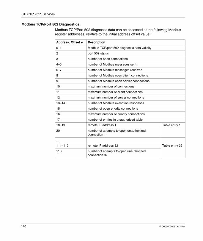
STB NIP 2311 Services
Modbus TCP/Port 502 Diagnostics
Modbus TCP/Port 502 diagnostic data can be accessed at the following Modbus register addresses, relative to the initial address offset value:
Address: Offset + Description
0–1 Modbus TCP/port 502 diagnostic data validity
2 port 502 status
3 number of open connections
4–5 number of Modbus messages sent
6–7 number of Modbus messages received
8 number of Modbus open client connections
9 number of Modbus open server connections
10 maximum number of connections
11 maximum number of client connections
12 maximum number of server connections
13–14 number of Modbus exception responses
15 number of open priority connections
16 maximum number of priority connections
17 number of entries in unauthorized table
18–19 remote IP address 1 Table entry 1
20 number of attempts to open unauthorized connection 1
...
111–112 remote IP address 32 Table entry 32
113 number of attempts to open unauthorized connection 32
140 EIO0000000051 6/2010
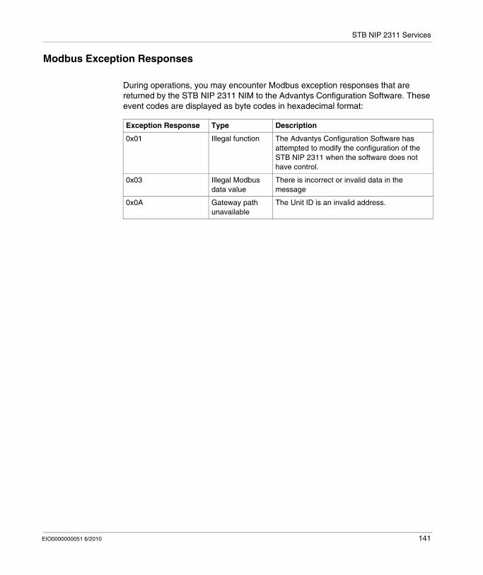
STB NIP 2311 Services
Modbus Exception Responses
During operations, you may encounter Modbus exception responses that are returned by the STB NIP 2311 NIM to the Advantys Configuration Software. These event codes are displayed as byte codes in hexadecimal format:
Exception Response Type Description
0x01 Illegal function The Advantys Configuration Software has attempted to modify the configuration of the STB NIP 2311 when the software does not have control.
0x03 Illegal Modbus data value
There is incorrect or invalid data in the message
0x0A Gateway path unavailable
The Unit ID is an invalid address.
EIO0000000051 6/2010 141
STB NIP 2311 Services
7.2 Server-Assigned IP Parameters
Assignment of IP Parameters from a Server
Introduction
The STB NIP 2311 NIM can receive an IP address using either the DHCP or BootP service.
Refer to IP Parameters chapter (see page 73) for information on how these services are implemented in the STB NIP 2311, including the specific IP assignment sequence.
DHCP
DHCP manages network addressing parameters for networked devices (in compliance with RFC 1531).
A DHCP server stores a list of device names and associated IP parameter settings for every client device on the network. It dynamically assigns IP addressing settings in response to client requests. A DHCP server responds to both DHCP and BootP (a subset of DHCP) requests.
The STB NIP 2311 network interface module implements DHCP as a client. Its IP parameters can be dynamically assigned by a DHCP IP address server.
BootP
The Bootstrap Protocol (BootP) assigns IP addresses to nodes on an Ethernet network (in compliance with RFC 951). Clients on the network issue BootP requests during their initialization sequence.
A BootP server stores a list of MAC addresses and associated IP parameter settings for every client device on the network. After receiving a request, the server responds by assigning IP parameter settings to the BootP client.
The STB NIP 2311 network interface module implements BootP as a client. A BootP client transmits requests on the network every second until it receives a reply from an IP address server.
142 EIO0000000051 6/2010
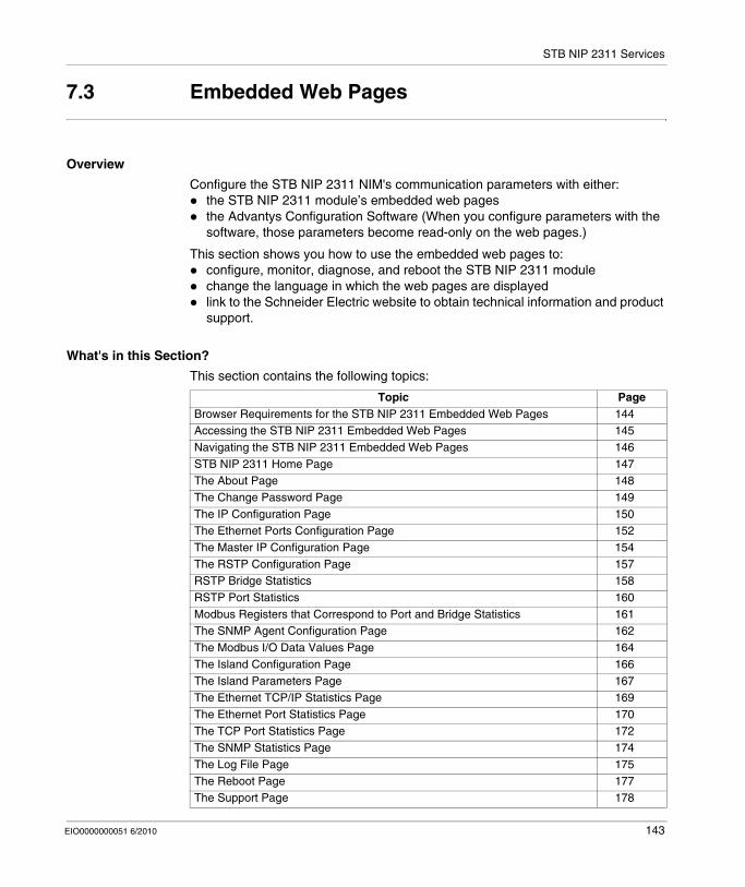
STB NIP 2311 Services
7.3 Embedded Web Pages
Overview
Configure the STB NIP 2311 NIM's communication parameters with either:the STB NIP 2311 module’s embedded web pagesthe Advantys Configuration Software (When you configure parameters with the software, those parameters become read-only on the web pages.)
This section shows you how to use the embedded web pages to:configure, monitor, diagnose, and reboot the STB NIP 2311 modulechange the language in which the web pages are displayedlink to the Schneider Electric website to obtain technical information and product support.
What's in this Section?
This section contains the following topics:
Topic PageBrowser Requirements for the STB NIP 2311 Embedded Web Pages 144Accessing the STB NIP 2311 Embedded Web Pages 145Navigating the STB NIP 2311 Embedded Web Pages 146STB NIP 2311 Home Page 147The About Page 148The Change Password Page 149The IP Configuration Page 150The Ethernet Ports Configuration Page 152The Master IP Configuration Page 154The RSTP Configuration Page 157RSTP Bridge Statistics 158RSTP Port Statistics 160Modbus Registers that Correspond to Port and Bridge Statistics 161The SNMP Agent Configuration Page 162The Modbus I/O Data Values Page 164The Island Configuration Page 166The Island Parameters Page 167The Ethernet TCP/IP Statistics Page 169The Ethernet Port Statistics Page 170The TCP Port Statistics Page 172The SNMP Statistics Page 174The Log File Page 175The Reboot Page 177The Support Page 178
EIO0000000051 6/2010 143
STB NIP 2311 Services
Browser Requirements for the STB NIP 2311 Embedded Web Pages
Introduction
The STB NIP 2311 network interface module’s embedded web pages can be accessed using a web browser.
Browser Requirements
To access the STB NIP 2311 network interface module’s web pages (see page 145), you need:
Internet Explorer version 5.0 or greaterJava Runtime Environment version 1.4.2 or greater1024 x 768 resolution (recommended for best viewing)
144 EIO0000000051 6/2010
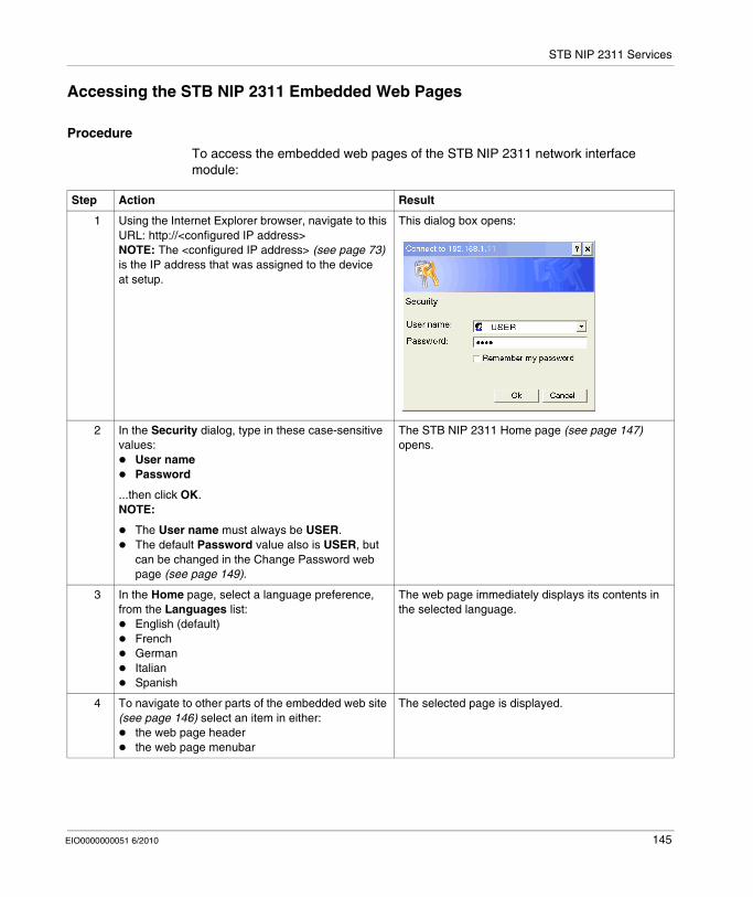
STB NIP 2311 Services
Accessing the STB NIP 2311 Embedded Web Pages
Procedure
To access the embedded web pages of the STB NIP 2311 network interface module:
Step Action Result
1 Using the Internet Explorer browser, navigate to this URL: http://<configured IP address>NOTE: The <configured IP address> (see page 73) is the IP address that was assigned to the device at setup.
This dialog box opens:
2 In the Security dialog, type in these case-sensitive values:
User namePassword
...then click OK.NOTE:
The User name must always be USER.The default Password value also is USER, but can be changed in the Change Password web page (see page 149).
The STB NIP 2311 Home page (see page 147) opens.
3 In the Home page, select a language preference, from the Languages list:
English (default)FrenchGermanItalianSpanish
The web page immediately displays its contents in the selected language.
4 To navigate to other parts of the embedded web site (see page 146) select an item in either:
the web page headerthe web page menubar
The selected page is displayed.
EIO0000000051 6/2010 145
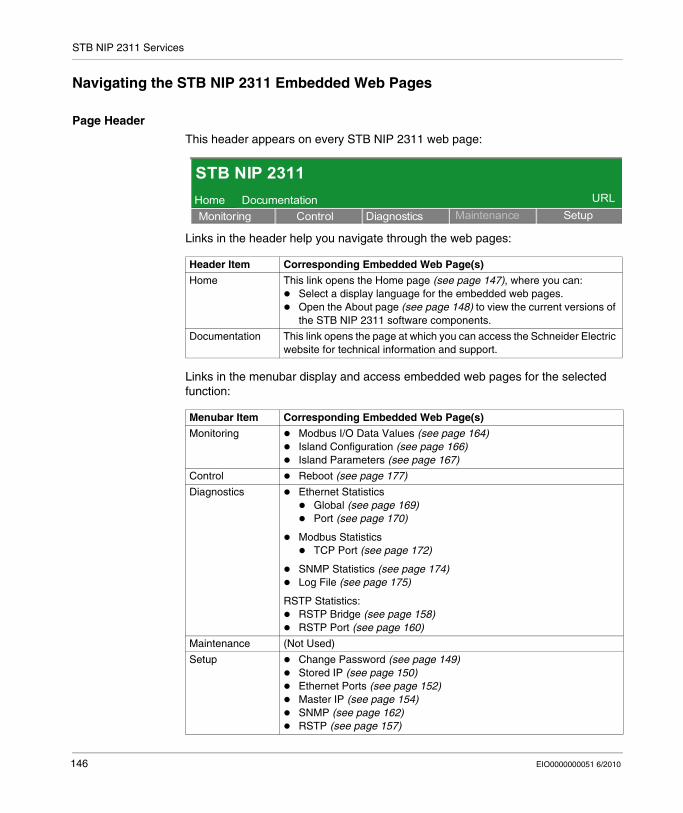
STB NIP 2311 Services
Navigating the STB NIP 2311 Embedded Web Pages
Page Header
This header appears on every STB NIP 2311 web page:
Links in the header help you navigate through the web pages:
Links in the menubar display and access embedded web pages for the selected function:
Header Item Corresponding Embedded Web Page(s)
Home This link opens the Home page (see page 147), where you can:Select a display language for the embedded web pages.Open the About page (see page 148) to view the current versions of the STB NIP 2311 software components.
Documentation This link opens the page at which you can access the Schneider Electric website for technical information and support.
Menubar Item Corresponding Embedded Web Page(s)
Monitoring Modbus I/O Data Values (see page 164)Island Configuration (see page 166)Island Parameters (see page 167)
Control Reboot (see page 177)
Diagnostics Ethernet StatisticsGlobal (see page 169)Port (see page 170)
Modbus StatisticsTCP Port (see page 172)
SNMP Statistics (see page 174)Log File (see page 175)
RSTP Statistics:RSTP Bridge (see page 158)RSTP Port (see page 160)
Maintenance (Not Used)
Setup Change Password (see page 149)Stored IP (see page 150)Ethernet Ports (see page 152)Master IP (see page 154)SNMP (see page 162)RSTP (see page 157)
STB NIP 2311Documentation
Monitoring Control Diagnostics Maintenance SetupURLHome
146 EIO0000000051 6/2010

STB NIP 2311 Services
STB NIP 2311 Home Page
Introduction
The Home page opens by default when you open the STB NIP 2311 NIM’s embedded web pages (after entering your user name and password).
The Home Page
Functions of the Home page:Select a display language for the module’s embedded web pages.Open the About page (see page 148) to view the current versions for these STB NIP 2311 software components:
bootloaderexecutableembedded web pages
The Home page looks like this:
Opening the Home Page
To open the Home page:
To open the Home page from any embedded web page:Click Home in the web page header.
STB NIP 2311Documentation
Monitoring Control Diagnostics Maintenance SetupURL
Home
LanguagesEnglishFrenchGermanItalianSpanish
IdentificationAbout
Copyright © 2000-2009, Schneider Electric. All Rights Reserved.
NIP 2311RUNPWRERRSTS
TEST
Ethernet
Advantys
Telemecanique
Home
Step Action
1 Type the IP address of the STB NIP 2311 in your web browser’s address field.
2 Click Enter on your keyboard to open the Home page.
EIO0000000051 6/2010 147

STB NIP 2311 Services
The About Page
Introduction
The About web page displays the current versions of STB NIP 2311 software components.
Opening the About Page
To open the About page:
About Page
The About page looks like this:
Step Action
1 Navigate to the Home page (see page 147) by selecting Home in the header area of any web page.
2 In the Home page, select About (located beneath Identification on the left side of the page). The About page opens.
STB NIP 2311Documentation
Monitoring Control Diagnostics Maintenance SetupURL
Home
LanguagesEnglishFrenchGermanItalianSpanish
IdentificationAbout
Copyright © 2000-2009, Schneider Electric. All Rights Reserved.
Home
1.0.01.0.01.0.0
Bootloader Version:Exec Version:
Web Site Version:
ABOUT Help
148 EIO0000000051 6/2010
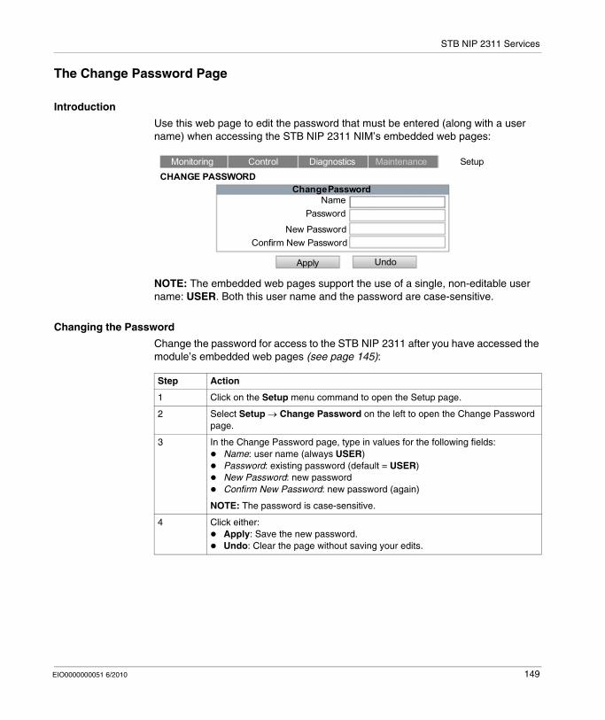
STB NIP 2311 Services
The Change Password Page
Introduction
Use this web page to edit the password that must be entered (along with a user name) when accessing the STB NIP 2311 NIM’s embedded web pages:
NOTE: The embedded web pages support the use of a single, non-editable user name: USER. Both this user name and the password are case-sensitive.
Changing the Password
Change the password for access to the STB NIP 2311 after you have accessed the module’s embedded web pages (see page 145):
Monitoring Control Diagnostics Maintenance Setup
NamePassword
New PasswordConfirm New Password
Apply Undo
CHANGE PASSWORDChange Password
Step Action
1 Click on the Setup menu command to open the Setup page.
2 Select Setup → Change Password on the left to open the Change Password page.
3 In the Change Password page, type in values for the following fields:Name: user name (always USER)Password: existing password (default = USER)New Password: new passwordConfirm New Password: new password (again)
NOTE: The password is case-sensitive.
4 Click either:Apply: Save the new password.Undo: Clear the page without saving your edits.
EIO0000000051 6/2010 149
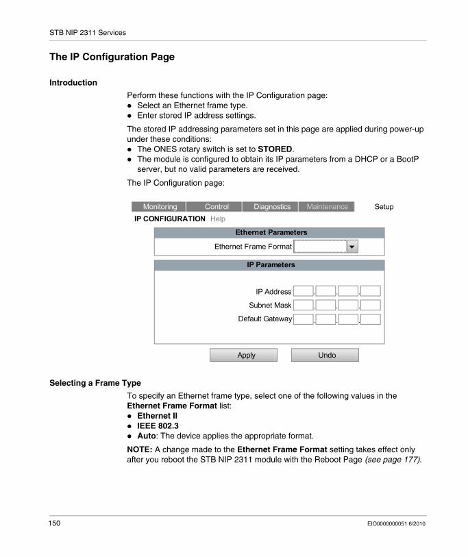
STB NIP 2311 Services
The IP Configuration Page
Introduction
Perform these functions with the IP Configuration page:Select an Ethernet frame type.Enter stored IP address settings.
The stored IP addressing parameters set in this page are applied during power-up under these conditions:
The ONES rotary switch is set to STORED.The module is configured to obtain its IP parameters from a DHCP or a BootP server, but no valid parameters are received.
The IP Configuration page:
Selecting a Frame Type
To specify an Ethernet frame type, select one of the following values in the Ethernet Frame Format list:
Ethernet IIIEEE 802.3Auto: The device applies the appropriate format.
NOTE: A change made to the Ethernet Frame Format setting takes effect only after you reboot the STB NIP 2311 module with the Reboot Page (see page 177).
Monitoring Control Diagnostics Maintenance SetupIP CONFIGURATION Help
Apply Undo
Ethernet Parameters
IP Parameters
Ethernet Frame Format
IP Address
Subnet Mask
Default Gateway
150 EIO0000000051 6/2010
STB NIP 2311 Services
Assigning a Stored IP Address
Enter a stored IP address for the STB NIP 2311 module after you have accessed the embedded web pages (see page 145):
NOTE: Changes made to the stored IP configuration and rotary switch settings take effect after you reboot the STB NIP 2311 module with the Reboot Page (see page 177) or after a power cycle of the module.
Step Action
1 Click the Setup menu command. The Setup page opens.
2 Select Stored IP on the left to open the IP Configuration page.
3 In the IP Configuration page, enter values for:IP Address: Enter four octet values (0...255) as a unique IP address. (The first octet must be in the range 1...126 or 128...233.)Subnet Mask: Enter four octet values (0...255).Default Gateway (optional): Enter four octet values (0...255). This value must reside on the same subnet as the IP address.
4 Click one of the following:Apply: Save the edited IP addressing parameters.Undo: Clear the page without saving your edits.
EIO0000000051 6/2010 151
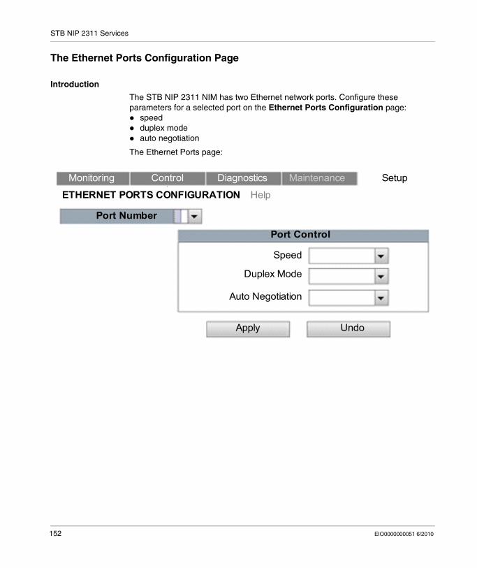
STB NIP 2311 Services
The Ethernet Ports Configuration Page
Introduction
The STB NIP 2311 NIM has two Ethernet network ports. Configure these parameters for a selected port on the Ethernet Ports Configuration page:
speedduplex modeauto negotiation
The Ethernet Ports page:
Monitoring Control Diagnostics Maintenance Setup
ETHERNET PORTS CONFIGURATION Help
Port Number
Port Control
Apply Undo
Speed
Duplex Mode
Auto Negotiation
152 EIO0000000051 6/2010
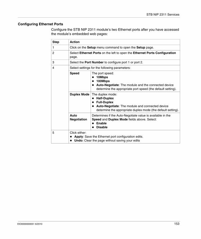
STB NIP 2311 Services
Configuring Ethernet Ports
Configure the STB NIP 2311 module’s two Ethernet ports after you have accessed the module’s embedded web pages:
Step Action
1 Click on the Setup menu command to open the Setup page.
2 Select Ethernet Ports on the left to open the Ethernet Ports Configuration page.
3 Select the Port Number to configure port 1 or port 2.
4 Select settings for the following parameters:
Speed The port speed:10Mbps100MbpsAuto-Negotiate: The module and the connected device determine the appropriate port speed (the default setting).
Duplex Mode The duplex mode:Half-DuplexFull-DuplexAuto-Negotiate: The module and connected device determine the appropriate duplex mode (the default setting).
Auto Negotiation
Determines if the Auto-Negotiate value is available in the Speed and Duplex Mode fields above. Select:
EnableDisable
5 Click either:Apply: Save the Ethernet port configuration edits.Undo: Clear the page without saving your edits
EIO0000000051 6/2010 153
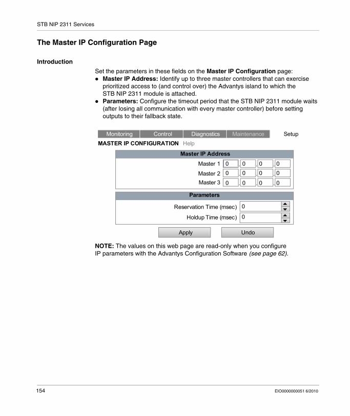
STB NIP 2311 Services
The Master IP Configuration Page
Introduction
Set the parameters in these fields on the Master IP Configuration page:Master IP Address: Identify up to three master controllers that can exercise prioritized access to (and control over) the Advantys island to which the STB NIP 2311 module is attached.Parameters: Configure the timeout period that the STB NIP 2311 module waits (after losing all communication with every master controller) before setting outputs to their fallback state.
NOTE: The values on this web page are read-only when you configure IP parameters with the Advantys Configuration Software (see page 62).
Monitoring Control Diagnostics Maintenance SetupMASTER IP CONFIGURATION Help
Apply Undo
Master IP AddressMaster 1
Master 2Master 3
Parameters
Reservation Time (msec)
Holdup Time (msec)
0 0 0 00 0 0 0
0 0 0 0
0
0
154 EIO0000000051 6/2010
STB NIP 2311 Services
Understanding Processing Control
The STB NIP 2311 module can be configured to recognize up to three controllers as master controllers. The module should continuously maintain an open connection with at least one master controller.
If the STB NIP 2311 module loses all connections with master controllers:It waits a prescribed time (Holdup Time) for a master controller to establish a new connection with the STB NIP 2311 module.If no new connection is established before the timeout period expires, the STB NIP 2311 module sets island outputs to their fallback states.
Understanding Connection Priority
The STB NIP 2311 module can maintain up to 16 simultaneous Modbus TCP connections, with one or more Ethernet devices.
Any controller on the Ethernet network can connect to the STB NIP 2311 module and write to:
the Advantys island’s output data process imagethe Advantys island’s configuration settings
Ordinarily, the STB NIP 2311 module grants connection requests on a first-come/first-serve basis. Once granted, a connection remains open until the device ceases to communicate with the STB NIP 2311.
When a master controller requests a connection, its request is given priority over other non-master controllers, even if the non-master controller is already connected to the STB NIP 2311.
When the STB NIP 2311 module reaches its maximum number of 16 simultaneous connections, it must close an existing connection before it can open a new one. The NIM closes existing connections based on the time of a connection’s most recent transaction; it closes the connection whose most recent transaction is the oldest. However, all connections between the STB NIP 2311 and a master controller are preserved. The controller does not close a connection with a master in order to open a new connection.
EIO0000000051 6/2010 155
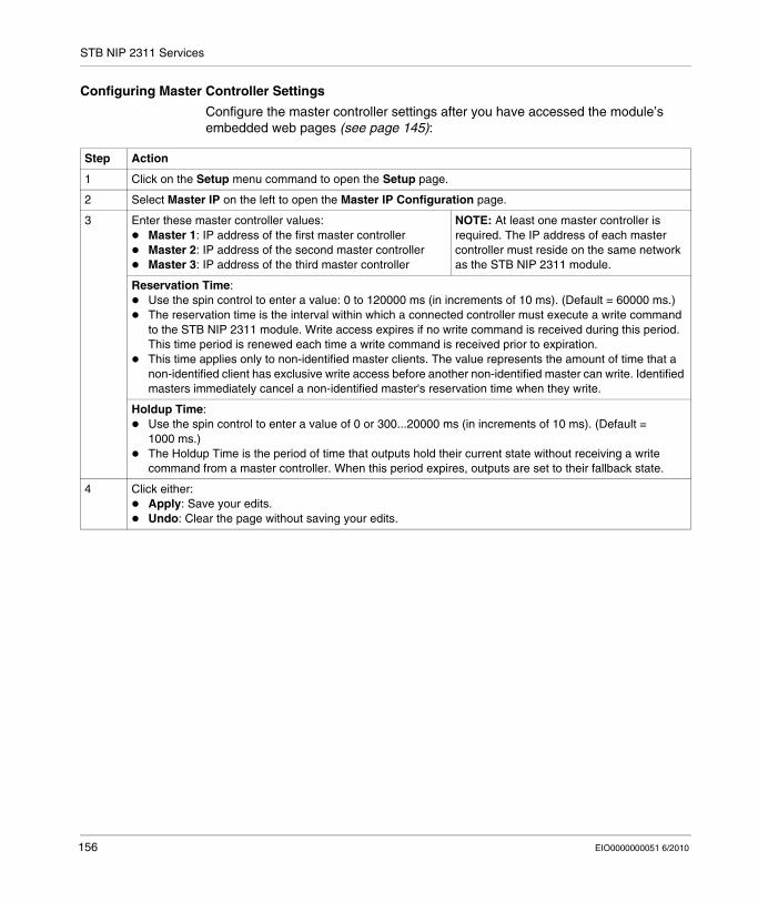
STB NIP 2311 Services
Configuring Master Controller Settings
Configure the master controller settings after you have accessed the module’s embedded web pages (see page 145):
Step Action
1 Click on the Setup menu command to open the Setup page.
2 Select Master IP on the left to open the Master IP Configuration page.
3 Enter these master controller values:Master 1: IP address of the first master controllerMaster 2: IP address of the second master controllerMaster 3: IP address of the third master controller
NOTE: At least one master controller is required. The IP address of each master controller must reside on the same network as the STB NIP 2311 module.
Reservation Time:Use the spin control to enter a value: 0 to 120000 ms (in increments of 10 ms). (Default = 60000 ms.)The reservation time is the interval within which a connected controller must execute a write command to the STB NIP 2311 module. Write access expires if no write command is received during this period. This time period is renewed each time a write command is received prior to expiration.This time applies only to non-identified master clients. The value represents the amount of time that a non-identified client has exclusive write access before another non-identified master can write. Identified masters immediately cancel a non-identified master's reservation time when they write.
Holdup Time:Use the spin control to enter a value of 0 or 300...20000 ms (in increments of 10 ms). (Default = 1000 ms.)The Holdup Time is the period of time that outputs hold their current state without receiving a write command from a master controller. When this period expires, outputs are set to their fallback state.
4 Click either:Apply: Save your edits.Undo: Clear the page without saving your edits.
156 EIO0000000051 6/2010
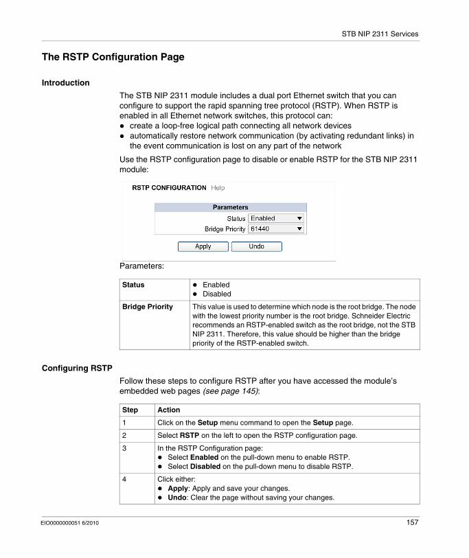
STB NIP 2311 Services
The RSTP Configuration Page
Introduction
The STB NIP 2311 module includes a dual port Ethernet switch that you can configure to support the rapid spanning tree protocol (RSTP). When RSTP is enabled in all Ethernet network switches, this protocol can:
create a loop-free logical path connecting all network devicesautomatically restore network communication (by activating redundant links) in the event communication is lost on any part of the network
Use the RSTP configuration page to disable or enable RSTP for the STB NIP 2311 module:
Parameters:
Configuring RSTP
Follow these steps to configure RSTP after you have accessed the module’s embedded web pages (see page 145):
Status EnabledDisabled
Bridge Priority This value is used to determine which node is the root bridge. The node with the lowest priority number is the root bridge. Schneider Electric recommends an RSTP-enabled switch as the root bridge, not the STB NIP 2311. Therefore, this value should be higher than the bridge priority of the RSTP-enabled switch.
Step Action
1 Click on the Setup menu command to open the Setup page.
2 Select RSTP on the left to open the RSTP configuration page.
3 In the RSTP Configuration page:Select Enabled on the pull-down menu to enable RSTP.Select Disabled on the pull-down menu to disable RSTP.
4 Click either:Apply: Apply and save your changes.Undo: Clear the page without saving your changes.
EIO0000000051 6/2010 157
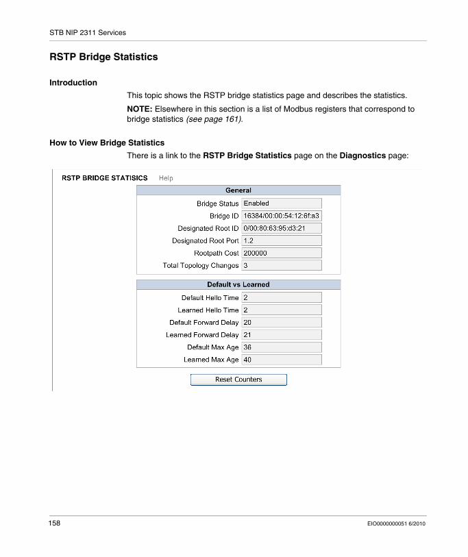
STB NIP 2311 Services
RSTP Bridge Statistics
Introduction
This topic shows the RSTP bridge statistics page and describes the statistics.
NOTE: Elsewhere in this section is a list of Modbus registers that correspond to bridge statistics (see page 161).
How to View Bridge Statistics
There is a link to the RSTP Bridge Statistics page on the Diagnostics page:
158 EIO0000000051 6/2010
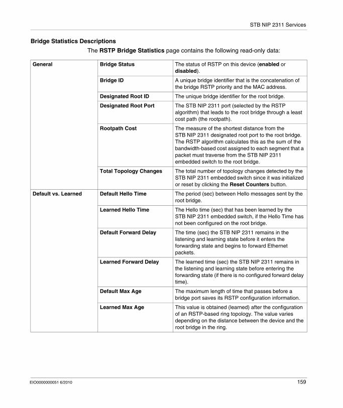
STB NIP 2311 Services
Bridge Statistics Descriptions
The RSTP Bridge Statistics page contains the following read-only data:
General Bridge Status The status of RSTP on this device (enabled or disabled).
Bridge ID A unique bridge identifier that is the concatenation of the bridge RSTP priority and the MAC address.
Designated Root ID The unique bridge identifier for the root bridge.
Designated Root Port The STB NIP 2311 port (selected by the RSTP algorithm) that leads to the root bridge through a least cost path (the rootpath).
Rootpath Cost The measure of the shortest distance from the STB NIP 2311 designated root port to the root bridge. The RSTP algorithm calculates this as the sum of the bandwidth-based cost assigned to each segment that a packet must traverse from the STB NIP 2311 embedded switch to the root bridge.
Total Topology Changes The total number of topology changes detected by the STB NIP 2311 embedded switch since it was initialized or reset by clicking the Reset Counters button.
Default vs. Learned Default Hello Time The period (sec) between Hello messages sent by the root bridge.
Learned Hello Time The Hello time (sec) that has been learned by the STB NIP 2311 embedded switch, if the Hello Time has not been configured on the root bridge.
Default Forward Delay The time (sec) the STB NIP 2311 remains in the listening and learning state before it enters the forwarding state and begins to forward Ethernet packets.
Learned Forward Delay The learned time (sec) the STB NIP 2311 remains in the listening and learning state before entering the forwarding state (if there is no configured forward delay time).
Default Max Age The maximum length of time that passes before a bridge port saves its RSTP configuration information.
Learned Max Age This value is obtained (learned) after the configuration of an RSTP-based ring topology. The value varies depending on the distance between the device and the root bridge in the ring.
EIO0000000051 6/2010 159
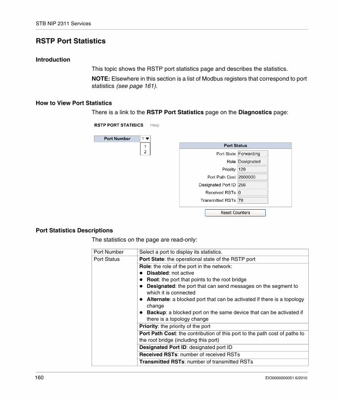
STB NIP 2311 Services
RSTP Port Statistics
Introduction
This topic shows the RSTP port statistics page and describes the statistics.
NOTE: Elsewhere in this section is a list of Modbus registers that correspond to port statistics (see page 161).
How to View Port Statistics
There is a link to the RSTP Port Statistics page on the Diagnostics page:
Port Statistics Descriptions
The statistics on the page are read-only:
Port Number Select a port to display its statistics.Port Status Port State: the operational state of the RSTP port
Role: the role of the port in the network:Disabled: not activeRoot: the port that points to the root bridgeDesignated: the port that can send messages on the segment to which it is connectedAlternate: a blocked port that can be activated if there is a topology changeBackup: a blocked port on the same device that can be activated if there is a topology change
Priority: the priority of the portPort Path Cost: the contribution of this port to the path cost of paths to the root bridge (including this port)Designated Port ID: designated port IDReceived RSTs: number of received RSTsTransmitted RSTs: number of transmitted RSTs
160 EIO0000000051 6/2010

STB NIP 2311 Services
Modbus Registers that Correspond to Port and Bridge Statistics
Register Table
This table contains the Modbus registers that correspond to the RSTP port stastics (see page 160) and bridge statistics (see page 158):
Field Name Size (bytes) Modbus Base 4x Register Address
State 2 410115
Bridge Priority 2 410116
Hello Time 2 410117
Max Age Time 2 410118
Transmit Count 2 410119
Forward Delay 2 410120
Port Count 2 410121
Port 1 Priority 2 410122
Port 1 Path Cost 4 410123
Port 2 Priority 2 410126
Port 2 Path Cost 4 410127
EIO0000000051 6/2010 161
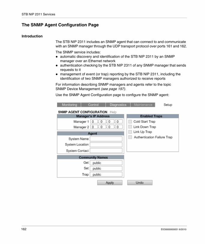
STB NIP 2311 Services
The SNMP Agent Configuration Page
Introduction
The STB NIP 2311 includes an SNMP agent that can connect to and communicate with an SNMP manager through the UDP transport protocol over ports 161 and 162.
The SNMP service includes:automatic discovery and identification of the STB NIP 2311 by an SNMP manager over an Ethernet networkauthentication checking by the STB NIP 2311 of any SNMP manager that sends requests to itmanagement of event (or trap) reporting by the STB NIP 2311, including the identification of two SNMP managers authorized to receive reports
For information describing SNMP managers and agents refer to the topic SNMP Device Management (see page 197).
Use the SNMP Agent Configuration page to configure the SNMP agent:
162 EIO0000000051 6/2010
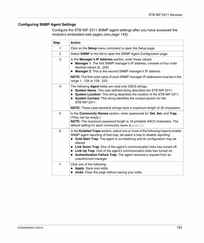
STB NIP 2311 Services
Configuring SNMP Agent Settings
Configure the STB NIP 2311 SNMP agent settings after you have accessed the module’s embedded web pages (see page 145):
Step Action
1 Click on the Setup menu command to open the Setup page.
2 Select SNMP to the left to open the SNMP Agent Configuration page.
3 In the Manager’s IP Address section, enter these values:Manager 1: The first SNMP manager’s IP address, consists of four octet decimal values (0...255)Manager 2: This is the second SNMP manager’s IP address.
NOTE: The first octet value of each SNMP manager IP addresses must be in the range 1...126 or 128...223.
4 The following Agent fields are read-only ASCII strings:System Name: This user-defined string describes the STB NIP 2311.System Location: This string describes the location of the STB NIP 2311.System Contact: This string identifies the contact person for the STB NIP 2311.
NOTE: These case-sensitive strings have a maximum length of 32 characters.
5 In the Community Names section, enter passwords for Get, Set, and Trap. (They can be empty.)NOTE: The maximum password length is 16 printable ASCII characters. The default setting for each community name is public.
6 In the Enabled Traps section, select one or more of the following traps to enable SNMP agent reporting of that trap; de-select a trap to disable reporting:
Cold Start Trap: The agent is re-initializing and its configuration may be altered.Link Down Trap: One of the agent’s communication links has turned off.Link Up Trap: One of the agent’s communication links has turned on.Authentication Failure Trap: The agent received a request from an unauthorized manager.
7 Click one of the following:Apply: Save your edits.Undo: Clear the page without saving your edits.
EIO0000000051 6/2010 163
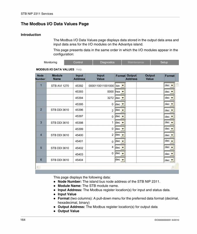
STB NIP 2311 Services
The Modbus I/O Data Values Page
Introduction
The Modbus I/O Data Values page displays data stored in the output data area and input data area for the I/O modules on the Advantys island.
This page presents data in the same order in which the I/O modules appear in the configuration:
This page displays the following data:Node Number: The island bus node address of the STB NIP 2311.Module Name: The STB module name.Input Address: The Modbus register location(s) for input and status data.Input ValueFormat (two columns): A pull-down menu for the preferred data format (decimal, hexadecimal, binary)Output Address: The Modbus register location(s) for output dataOutput Value
MODBUS I/O DATA VALUES Help
Monitoring Control Diagnostics Maintenance Setup
Node Number
Module Name
Input Address
Input Value
Format Output Address
Output Value
Format
STB AVI 12701 45392 0000110011001000 bin
2 STB DDI 3610
45393
45394
45395
45396
45397
3 STB DDI 3610 45398
45399
4 STB DDI 3610 45400
45401
5 STB DDI 3610 45402
45403
6 STB DDI 3610 45404
0000
3272
0
2
0
1
0
2
0
4
0
hex
dec
dec
dec
dec
dec
dec
dec
dec
dec
dec
dec
dec
dec
dec
dec
dec
dec
dec
dec
dec
dec
dec
dec
dec
164 EIO0000000051 6/2010

STB NIP 2311 Services
Accessing the Modbus I/O Data Values Page
Display the Modbus I/O Data Values page after first accessing the STB NIP 2311 module’s embedded web pages (see page 145):
Step Action
1 Select the Monitoring menu command in any web page to open the Monitoring page.
2 On the left side of the page, select Modbus I/O Data Values to open the Modbus I/O Data Values page.
EIO0000000051 6/2010 165
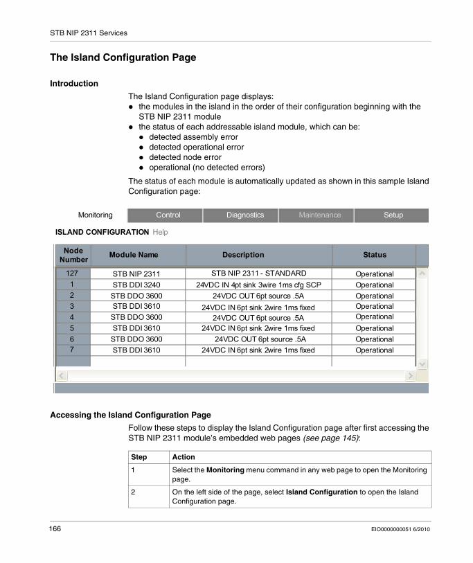
STB NIP 2311 Services
The Island Configuration Page
Introduction
The Island Configuration page displays:the modules in the island in the order of their configuration beginning with the STB NIP 2311 modulethe status of each addressable island module, which can be:
detected assembly errordetected operational errordetected node erroroperational (no detected errors)
The status of each module is automatically updated as shown in this sample Island Configuration page:
Accessing the Island Configuration Page
Follow these steps to display the Island Configuration page after first accessing the STB NIP 2311 module’s embedded web pages (see page 145):
ISLAND CONFIGURATION Help
Monitoring Control Diagnostics Maintenance Setup
STB DDI 3240STB DDO 3600STB DDI 3610STB DDO 3600STB DDI 3610
STB NIP 2311
Node Number Module Name
12712345
Description Status
STB NIP 2311 - STANDARD OperationalOperationalOperationalOperationalOperationalOperational
24VDC IN 4pt sink 3wire 1ms cfg SCP24VDC OUT 6pt source .5A
24VDC IN 6pt sink 2wire 1ms fixed24VDC OUT 6pt source .5A
24VDC IN 6pt sink 2wire 1ms fixed67
STB DDO 3600STB DDI 3610
24VDC OUT 6pt source .5A24VDC IN 6pt sink 2wire 1ms fixed
OperationalOperational
Step Action
1 Select the Monitoring menu command in any web page to open the Monitoring page.
2 On the left side of the page, select Island Configuration to open the Island Configuration page.
166 EIO0000000051 6/2010
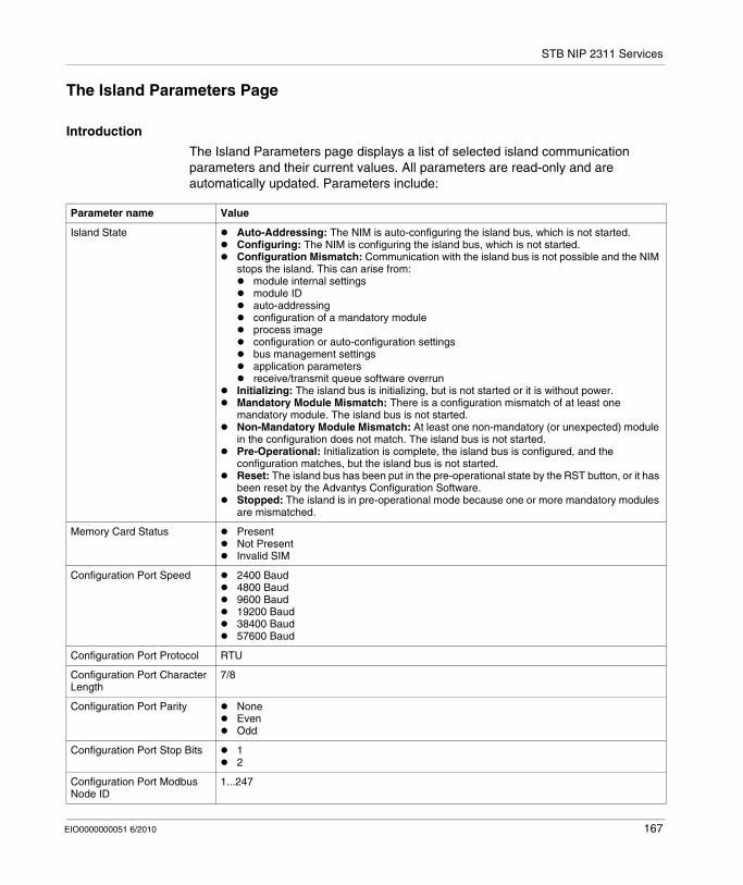
STB NIP 2311 Services
The Island Parameters Page
Introduction
The Island Parameters page displays a list of selected island communication parameters and their current values. All parameters are read-only and are automatically updated. Parameters include:
Parameter name Value
Island State Auto-Addressing: The NIM is auto-configuring the island bus, which is not started.Configuring: The NIM is configuring the island bus, which is not started.Configuration Mismatch: Communication with the island bus is not possible and the NIM stops the island. This can arise from:
module internal settingsmodule IDauto-addressingconfiguration of a mandatory moduleprocess imageconfiguration or auto-configuration settingsbus management settingsapplication parametersreceive/transmit queue software overrun
Initializing: The island bus is initializing, but is not started or it is without power.Mandatory Module Mismatch: There is a configuration mismatch of at least one mandatory module. The island bus is not started. Non-Mandatory Module Mismatch: At least one non-mandatory (or unexpected) module in the configuration does not match. The island bus is not started. Pre-Operational: Initialization is complete, the island bus is configured, and the configuration matches, but the island bus is not started. Reset: The island bus has been put in the pre-operational state by the RST button, or it has been reset by the Advantys Configuration Software.Stopped: The island is in pre-operational mode because one or more mandatory modules are mismatched.
Memory Card Status PresentNot PresentInvalid SIM
Configuration Port Speed 2400 Baud4800 Baud9600 Baud19200 Baud38400 Baud57600 Baud
Configuration Port Protocol RTU
Configuration Port Character Length
7/8
Configuration Port Parity NoneEvenOdd
Configuration Port Stop Bits 12
Configuration Port Modbus Node ID
1...247
EIO0000000051 6/2010 167
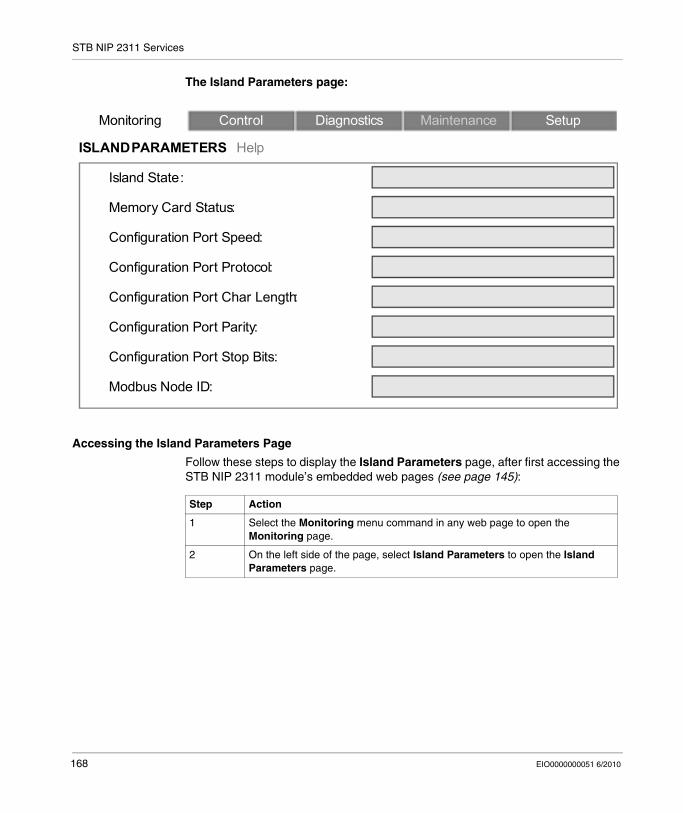
STB NIP 2311 Services
The Island Parameters page:
Accessing the Island Parameters Page
Follow these steps to display the Island Parameters page, after first accessing the STB NIP 2311 module’s embedded web pages (see page 145):
ISLAND PARAMETERS Help
Monitoring Control Diagnostics Maintenance Setup
Memory Card Status:
Configuration Port Speed:
Configuration Port Protocol:
Configuration Port Char Length:
Configuration Port Parity:
Island State:
Configuration Port Stop Bits:
Modbus Node ID:
Step Action
1 Select the Monitoring menu command in any web page to open the Monitoring page.
2 On the left side of the page, select Island Parameters to open the Island Parameters page.
168 EIO0000000051 6/2010
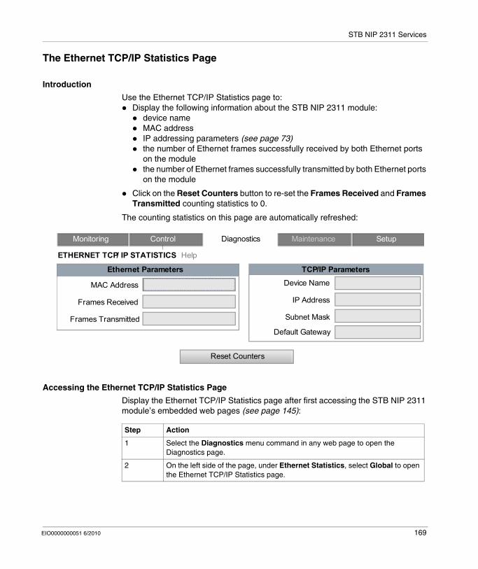
STB NIP 2311 Services
The Ethernet TCP/IP Statistics Page
Introduction
Use the Ethernet TCP/IP Statistics page to:Display the following information about the STB NIP 2311 module:
device nameMAC addressIP addressing parameters (see page 73)the number of Ethernet frames successfully received by both Ethernet ports on the modulethe number of Ethernet frames successfully transmitted by both Ethernet ports on the module
Click on the Reset Counters button to re-set the Frames Received and Frames Transmitted counting statistics to 0.
The counting statistics on this page are automatically refreshed:
Accessing the Ethernet TCP/IP Statistics Page
Display the Ethernet TCP/IP Statistics page after first accessing the STB NIP 2311 module’s embedded web pages (see page 145):
Monitoring Control Diagnostics Maintenance Setup
Ethernet Parameters
MAC Address
Frames Received
Frames Transmitted
TCP/IP ParametersDevice Name
IP Address
Subnet Mask
Default Gateway
Reset Counters
ETHERNET TCP/ IP STATISTICS Help
Step Action
1 Select the Diagnostics menu command in any web page to open the Diagnostics page.
2 On the left side of the page, under Ethernet Statistics, select Global to open the Ethernet TCP/IP Statistics page.
EIO0000000051 6/2010 169
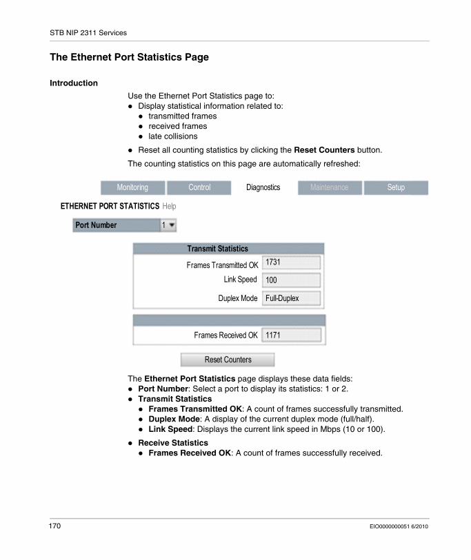
STB NIP 2311 Services
The Ethernet Port Statistics Page
Introduction
Use the Ethernet Port Statistics page to:Display statistical information related to:
transmitted framesreceived frameslate collisions
Reset all counting statistics by clicking the Reset Counters button.
The counting statistics on this page are automatically refreshed:
The Ethernet Port Statistics page displays these data fields:Port Number: Select a port to display its statistics: 1 or 2.Transmit Statistics
Frames Transmitted OK: A count of frames successfully transmitted.Duplex Mode: A display of the current duplex mode (full/half).Link Speed: Displays the current link speed in Mbps (10 or 100).
Receive StatisticsFrames Received OK: A count of frames successfully received.
Monitoring Control Diagnostics Maintenance Setup
Port Number
Frames Transmitted OK
Duplex Mode
Reset Counters
ETHERNET PORT STATISTICS Help
Transmit Statistics
1
Link Speed
Frames Received OK
1731
Full-Duplex
100
1171
170 EIO0000000051 6/2010

STB NIP 2311 Services
Accessing the Ethernet Port Statistics Page
Follow these steps to display the Ethernet Port Statistics page, after first accessing the STB NIP 2311 module’s embedded web pages (see page 145):
Step Action
1 Select the Diagnostics menu command in any web page to open the Diagnostics page.
2 On the left side of the page, under Ethernet Statistics, select Port to open the Ethernet Port Statistics page.
EIO0000000051 6/2010 171
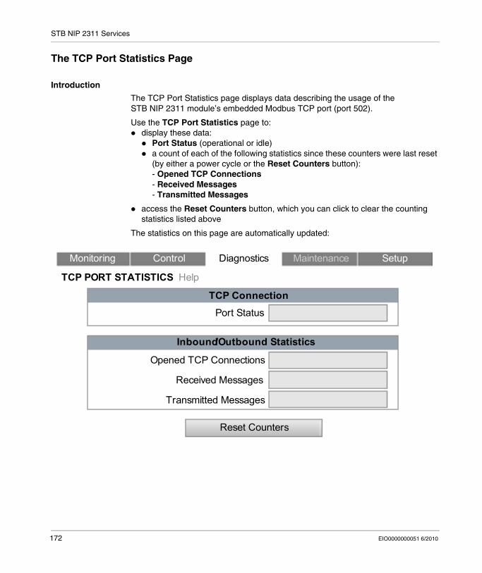
STB NIP 2311 Services
The TCP Port Statistics Page
Introduction
The TCP Port Statistics page displays data describing the usage of the STB NIP 2311 module’s embedded Modbus TCP port (port 502).
Use the TCP Port Statistics page to:display these data:
Port Status (operational or idle)a count of each of the following statistics since these counters were last reset (by either a power cycle or the Reset Counters button):- Opened TCP Connections- Received Messages- Transmitted Messages
access the Reset Counters button, which you can click to clear the counting statistics listed above
The statistics on this page are automatically updated:
Monitoring Control Diagnostics Maintenance Setup
TCP Connection
Reset Counters
TCP PORT STATISTICS Help
Inbound/Outbound Statistics
Opened TCP Connections
Received Messages
Transmitted Messages
Port Status
172 EIO0000000051 6/2010

STB NIP 2311 Services
Accessing the TCP Port Statistics Page
Display the TCP Port Statistics page after first accessing the STB NIP 2311 module’s embedded web pages (see page 145):
Step Action
1 Select the Diagnostics menu command in any web page to open the Diagnostics page.
2 On the left side of the page, under Modbus Statistics, select TCP Port to open the TCP Port Statistics page.
EIO0000000051 6/2010 173
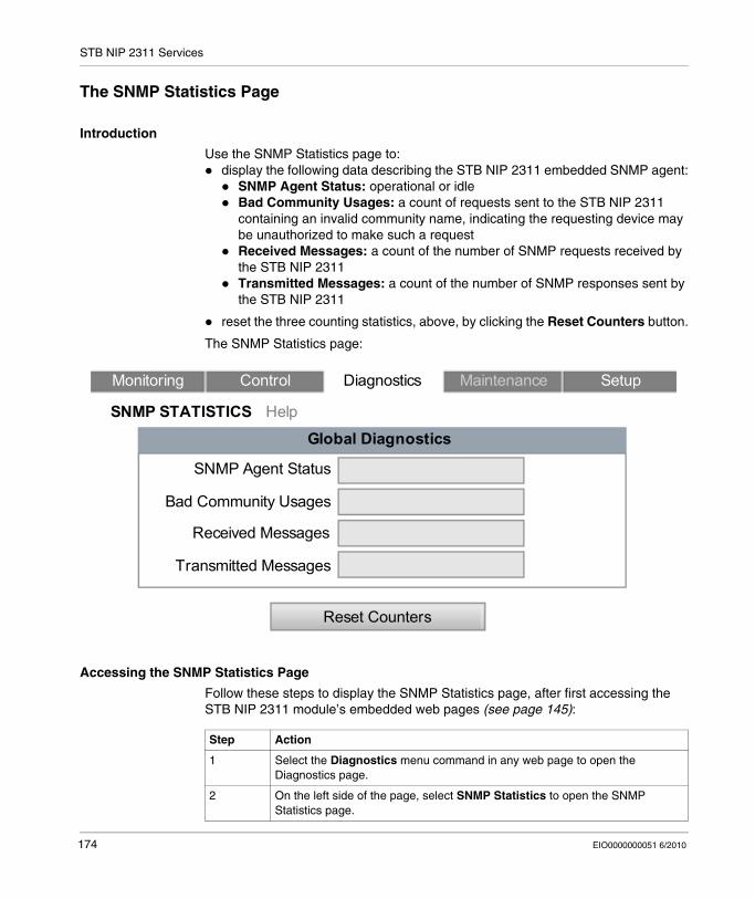
STB NIP 2311 Services
The SNMP Statistics Page
Introduction
Use the SNMP Statistics page to: display the following data describing the STB NIP 2311 embedded SNMP agent:
SNMP Agent Status: operational or idle Bad Community Usages: a count of requests sent to the STB NIP 2311 containing an invalid community name, indicating the requesting device may be unauthorized to make such a requestReceived Messages: a count of the number of SNMP requests received by the STB NIP 2311Transmitted Messages: a count of the number of SNMP responses sent by the STB NIP 2311
reset the three counting statistics, above, by clicking the Reset Counters button.
The SNMP Statistics page:
Accessing the SNMP Statistics Page
Follow these steps to display the SNMP Statistics page, after first accessing the STB NIP 2311 module’s embedded web pages (see page 145):
Global Diagnostics
Monitoring Control Diagnostics Maintenance Setup
SNMP STATISTICS Help
SNMP Agent Status
Bad Community Usages
Received Messages
Transmitted Messages
Reset Counters
Step Action
1 Select the Diagnostics menu command in any web page to open the Diagnostics page.
2 On the left side of the page, select SNMP Statistics to open the SNMP Statistics page.
174 EIO0000000051 6/2010
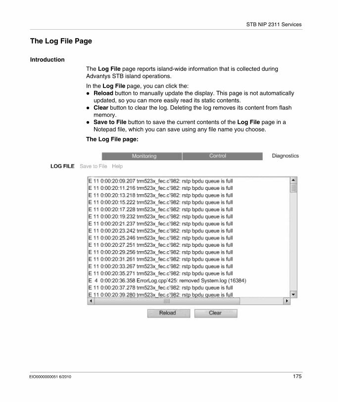
STB NIP 2311 Services
The Log File Page
Introduction
The Log File page reports island-wide information that is collected during Advantys STB island operations.
In the Log File page, you can click the:Reload button to manually update the display. This page is not automatically updated, so you can more easily read its static contents.Clear button to clear the log. Deleting the log removes its content from flash memory.Save to File button to save the current contents of the Log File page in a Notepad file, which you can save using any file name you choose.
The Log File page:
EIO0000000051 6/2010 175

STB NIP 2311 Services
Accessing the Log File Page
Display the Log File page, after first accessing the STB NIP 2311 module’s embedded web pages (see page 145):
Step Action
1 Select the Diagnostics menu command in any web page to open the Diagnostics page.
2 On the left side of the page, select Log File to open the Log File page.
176 EIO0000000051 6/2010
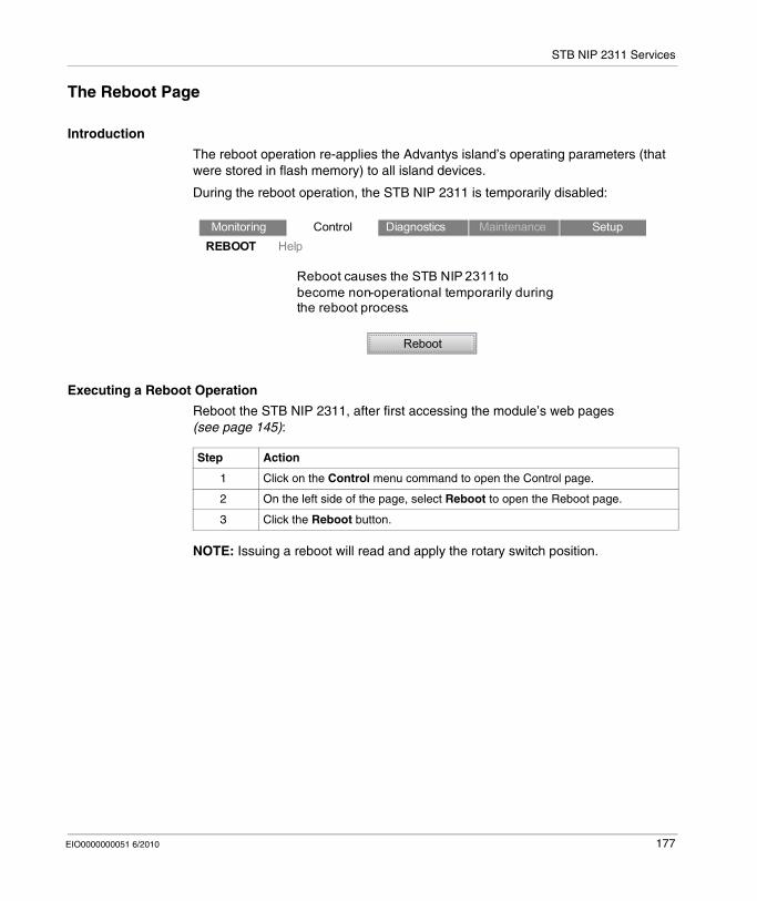
STB NIP 2311 Services
The Reboot Page
Introduction
The reboot operation re-applies the Advantys island’s operating parameters (that were stored in flash memory) to all island devices.
During the reboot operation, the STB NIP 2311 is temporarily disabled:
Executing a Reboot Operation
Reboot the STB NIP 2311, after first accessing the module’s web pages (see page 145):
NOTE: Issuing a reboot will read and apply the rotary switch position.
Reboot causes the STB NIP 2311 to become non-operational temporarily during the reboot process.
Reboot
Monitoring Control Diagnostics Maintenance SetupREBOOT Help
Step Action
1 Click on the Control menu command to open the Control page.
2 On the left side of the page, select Reboot to open the Reboot page.
3 Click the Reboot button.
EIO0000000051 6/2010 177
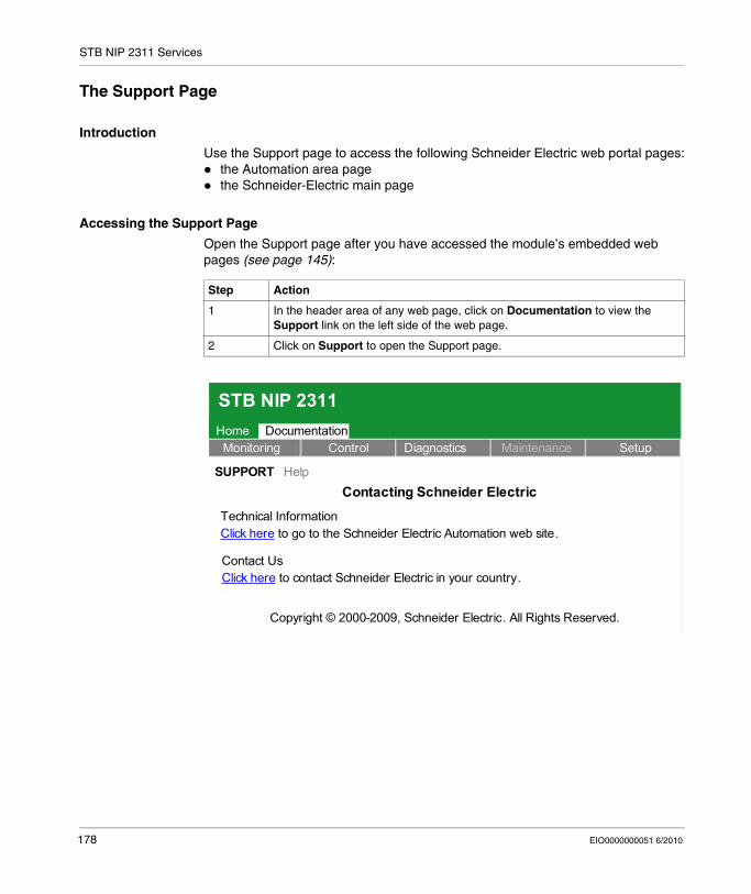
STB NIP 2311 Services
The Support Page
Introduction
Use the Support page to access the following Schneider Electric web portal pages:the Automation area page the Schneider-Electric main page
Accessing the Support Page
Open the Support page after you have accessed the module’s embedded web pages (see page 145):
Step Action
1 In the header area of any web page, click on Documentation to view the Support link on the left side of the web page.
2 Click on Support to open the Support page.
STB NIP 2311Documentation
Monitoring Control Diagnostics Maintenance SetupHome
SUPPORT Help
Copyright © 2000-2009, Schneider Electric. All Rights Reserved.
Contacting Schneider Electric
Technical InformationClick here to go to the Schneider Electric Automation web site.
Contact UsClick here to contact Schneider Electric in your country.
178 EIO0000000051 6/2010
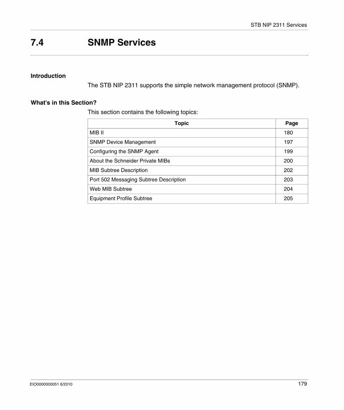
STB NIP 2311 Services
7.4 SNMP Services
Introduction
The STB NIP 2311 supports the simple network management protocol (SNMP).
What's in this Section?
This section contains the following topics:
Topic Page
MIB II 180
SNMP Device Management 197
Configuring the SNMP Agent 199
About the Schneider Private MIBs 200
MIB Subtree Description 202
Port 502 Messaging Subtree Description 203
Web MIB Subtree 204
Equipment Profile Subtree 205
EIO0000000051 6/2010 179
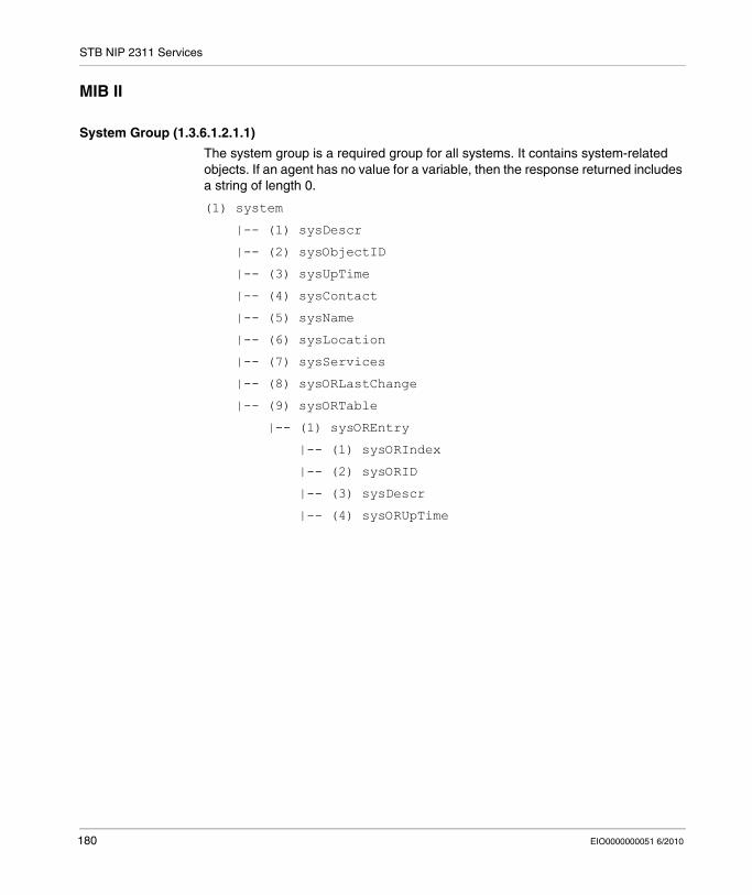
STB NIP 2311 Services
MIB II
System Group (1.3.6.1.2.1.1)
The system group is a required group for all systems. It contains system-related objects. If an agent has no value for a variable, then the response returned includes a string of length 0.
(1) system
|-- (1) sysDescr
|-- (2) sysObjectID
|-- (3) sysUpTime
|-- (4) sysContact
|-- (5) sysName
|-- (6) sysLocation
|-- (7) sysServices
|-- (8) sysORLastChange
|-- (9) sysORTable
|-- (1) sysOREntry
|-- (1) sysORIndex
|-- (2) sysORID
|-- (3) sysDescr
|-- (4) sysORUpTime
180 EIO0000000051 6/2010
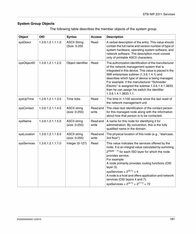
STB NIP 2311 Services
System Group Objects
The following table describes the member objects of the system group.
Object OID Syntax Access Description
sysDescr 1.3.6.1.2.1.1.1.0 ASCII String (Size: 0-255
Read A verbal description of the entry. This value should contain the full name and version number of type of system hardware, operating system software, and network software. The description must consist only of printable ASCII characters.
sysObjectID 1.3.6.1.2.1.1.2.0 Object identifier Read The authorization identification of the manufacturer of the network management system that is integrated in this device. This value is placed in the SMI enterprises subtree (1.3.6.1.4.1) and describes which type of device is being managed. For example: if the manufacturer "Schneider Electric" is assigned the subtree 1.3.6.1.4.1.3833, then he can assign his switch the identifier 1.3.6.1.4.1.3833.1.1.
sysUpTime 1.3.6.1.2.1.1.3.0 Time ticks Read The time in 1/100 seconds since the last reset of the network management unit.
sysContact 1.3.6.1.2.1.1.4.0 ASCII string (size: 0-255)
Read and write
The clear-text identification of the contact person for this managed node along with the information about how that person is to be contacted.
sysName 1.3.6.1.2.1.1.5.0 ASCII string (size: 0-255)
Read and write
A name for this node for identifying it for administration. By convention, this is the fully qualified name in the domain.
sysLocation 1.3.6.1.2.1.1.6.0 ASCII string (size: 0-255)
Read and write
The physical location of this node (e.g., "staircase, 3rd floor")
sysServices 1.3.6.1.2.1.1.7.0 Integer (0-127) Read This value indicates the services offered by the node. It is an integral value calculated by summing
2(layer - 1) for each ISO layer for which the node provides service.For example:A node primarily provides routing functions (OSI layer 3):
sysServices = 2(3-1) = 4A node is a host and offers application and network services (OSI layers 4 and 7):
sysServices = 2(4-1) + 2(7-1) = 72
EIO0000000051 6/2010 181
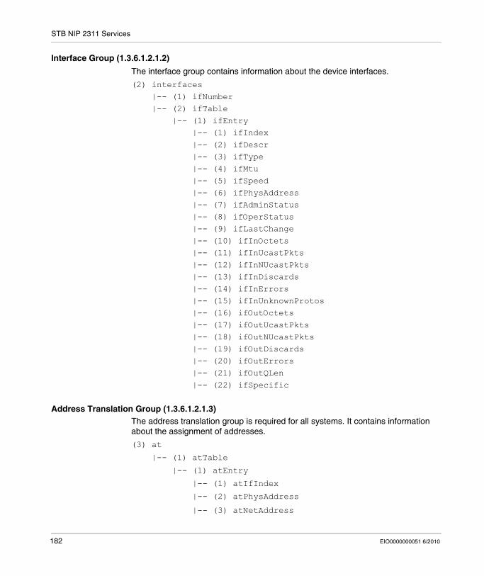
STB NIP 2311 Services
Interface Group (1.3.6.1.2.1.2)
The interface group contains information about the device interfaces.
(2) interfaces |-- (1) ifNumber |-- (2) ifTable |-- (1) ifEntry |-- (1) ifIndex |-- (2) ifDescr |-- (3) ifType |-- (4) ifMtu |-- (5) ifSpeed |-- (6) ifPhysAddress |-- (7) ifAdminStatus |-- (8) ifOperStatus |-- (9) ifLastChange |-- (10) ifInOctets |-- (11) ifInUcastPkts |-- (12) ifInNUcastPkts |-- (13) ifInDiscards |-- (14) ifInErrors |-- (15) ifInUnknownProtos |-- (16) ifOutOctets |-- (17) ifOutUcastPkts |-- (18) ifOutNUcastPkts |-- (19) ifOutDiscards |-- (20) ifOutErrors |-- (21) ifOutQLen |-- (22) ifSpecific
Address Translation Group (1.3.6.1.2.1.3)The address translation group is required for all systems. It contains information about the assignment of addresses.
(3) at
|-- (1) atTable
|-- (1) atEntry
|-- (1) atIfIndex
|-- (2) atPhysAddress
|-- (3) atNetAddress
182 EIO0000000051 6/2010
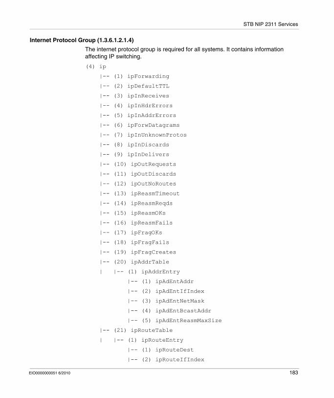
STB NIP 2311 Services
Internet Protocol Group (1.3.6.1.2.1.4)
The internet protocol group is required for all systems. It contains information affecting IP switching.
(4) ip
|-- (1) ipForwarding
|-- (2) ipDefaultTTL
|-- (3) ipInReceives
|-- (4) ipInHdrErrors
|-- (5) ipInAddrErrors
|-- (6) ipForwDatagrams
|-- (7) ipInUnknownProtos
|-- (8) ipInDiscards
|-- (9) ipInDelivers
|-- (10) ipOutRequests
|-- (11) ipOutDiscards
|-- (12) ipOutNoRoutes
|-- (13) ipReasmTimeout
|-- (14) ipReasmReqds
|-- (15) ipReasmOKs
|-- (16) ipReasmFails
|-- (17) ipFragOKs
|-- (18) ipFragFails
|-- (19) ipFragCreates
|-- (20) ipAddrTable
| |-- (1) ipAddrEntry
|-- (1) ipAdEntAddr
|-- (2) ipAdEntIfIndex
|-- (3) ipAdEntNetMask
|-- (4) ipAdEntBcastAddr
|-- (5) ipAdEntReasmMaxSize
|-- (21) ipRouteTable
| |-- (1) ipRouteEntry
|-- (1) ipRouteDest
|-- (2) ipRouteIfIndex
EIO0000000051 6/2010 183
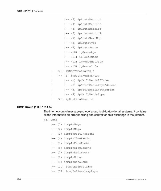
STB NIP 2311 Services
|-- (3) ipRouteMetric1
|-- (4) ipRouteMetric2
|-- (5) ipRouteMetric3
|-- (6) ipRouteMetric4
|-- (7) ipRouteNextHop
|-- (8) ipRouteType
|-- (9) ipRouteProto
|-- (10) ipRouteAge
|-- (11) ipRouteMask
|-- (12) ipRouteMetric5
|-- (13) ipRouteInfo
|-- (22) ipNetToMediaTable
| |-- (1) ipNetToMediaEntry
| |-- (1) ipNetToMediaIfIndex
| |-- (2) ipNetToMediaPhysAddress
| |-- (3) ipNetToMediaNetAddress
| |-- (4) ipNetToMediaType
|-- (23) ipRoutingDiscards
ICMP Group (1.3.6.1.2.1.5)
The internet control message protocol group is obligatory for all systems. It contains all the information on error handling and control for data exchange in the Internet.
(5) icmp
|-- (1) icmpInMsgs
|-- (2) icmpInMsgs
|-- (3) icmpInDestUnreachs
|-- (4) icmpInTimeExcds
|-- (5) icmpInParmProbs
|-- (6) icmpInSrcQuenchs
|-- (7) icmpInRedirects
|-- (8) icmpInEchos
|-- (9) icmpInEchoReps
|-- (10) icmpInTimestamps
|-- (11) icmpInTimestampReps
184 EIO0000000051 6/2010
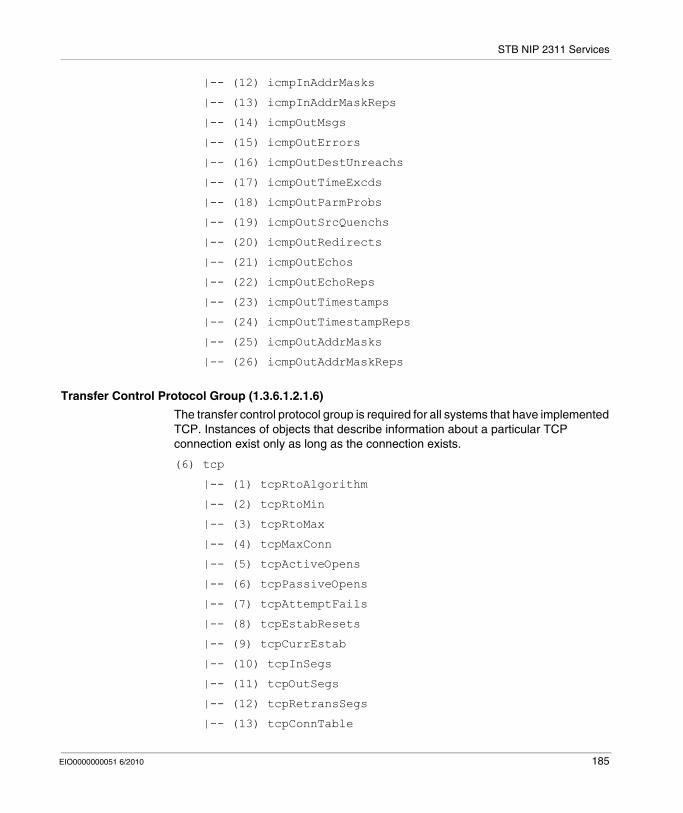
STB NIP 2311 Services
|-- (12) icmpInAddrMasks
|-- (13) icmpInAddrMaskReps
|-- (14) icmpOutMsgs
|-- (15) icmpOutErrors
|-- (16) icmpOutDestUnreachs
|-- (17) icmpOutTimeExcds
|-- (18) icmpOutParmProbs
|-- (19) icmpOutSrcQuenchs
|-- (20) icmpOutRedirects
|-- (21) icmpOutEchos
|-- (22) icmpOutEchoReps
|-- (23) icmpOutTimestamps
|-- (24) icmpOutTimestampReps
|-- (25) icmpOutAddrMasks
|-- (26) icmpOutAddrMaskReps
Transfer Control Protocol Group (1.3.6.1.2.1.6)
The transfer control protocol group is required for all systems that have implemented TCP. Instances of objects that describe information about a particular TCP connection exist only as long as the connection exists.
(6) tcp
|-- (1) tcpRtoAlgorithm
|-- (2) tcpRtoMin
|-- (3) tcpRtoMax
|-- (4) tcpMaxConn
|-- (5) tcpActiveOpens
|-- (6) tcpPassiveOpens
|-- (7) tcpAttemptFails
|-- (8) tcpEstabResets
|-- (9) tcpCurrEstab
|-- (10) tcpInSegs
|-- (11) tcpOutSegs
|-- (12) tcpRetransSegs
|-- (13) tcpConnTable
EIO0000000051 6/2010 185
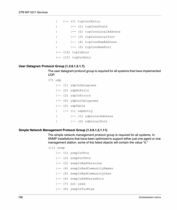
STB NIP 2311 Services
| |-- (1) tcpConnEntry
| |-- (1) tcpConnState
| |-- (2) tcpConnLocalAddress
| |-- (3) tcpConnLocalPort
| |-- (4) tcpConnRemAddress
| |-- (5) tcpConnRemPort
|-- (14) tcpInErrs
|-- (15) tcpOutRsts
User Datagram Protocol Group (1.3.6.1.2.1.7)
The user datagram protocol group is required for all systems that have implemented UDP.
(7) udp
|-- (1) udpInDatagrams
|-- (2) udpNoPorts
|-- (3) udpInErrors
|-- (4) udpOutDatagrams
|-- (5) udpTable
| |-- (1) udpEntry
| |-- (1) udpLocalAddress
| |-- (2) udpLocalPort
Simple Network Management Protocol Group (1.3.6.1.2.1.11)
The simple network management protocol group is required for all systems. In SNMP installations that have been optimized to support either just one agent or one management station, some of the listed objects will contain the value "0."
(11) snmp
|-- (1) snmpInPkts
|-- (2) snmpOutPkts
|-- (3) snmpInBadVersions
|-- (4) snmpInBadCommunityNames
|-- (5) snmpInBadCommunityUses
|-- (6) snmpInASNParseErrs
|-- (7) not used
|-- (8) snmpInTooBigs
186 EIO0000000051 6/2010
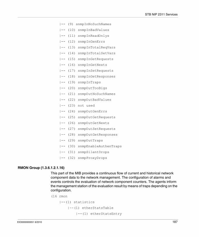
STB NIP 2311 Services
|-- (9) snmpInNoSuchNames
|-- (10) snmpInBadValues
|-- (11) snmpInReadOnlys
|-- (12) snmpInGenErrs
|-- (13) snmpInTotalReqVars
|-- (14) snmpInTotalSetVars
|-- (15) snmpInGetRequests
|-- (16) snmpInGetNexts
|-- (17) snmpInSetRequests
|-- (18) snmpInGetResponses
|-- (19) snmpInTraps
|-- (20) snmpOutTooBigs
|-- (21) snmpOutNoSuchNames
|-- (22) snmpOutBadValues
|-- (23) not used
|-- (24) snmpOutGenErrs
|-- (25) snmpOutGetRequests
|-- (26) snmpOutGetNexts
|-- (27) snmpOutSetRequests
|-- (28) snmpOutGetResponses
|-- (29) snmpOutTraps
|-- (30) snmpEnableAuthenTraps
|-- (31) snmpSilentDrops
|-- (32) snmpProxyDrops
RMON Group (1.3.6.1.2.1.16)
This part of the MIB provides a continuous flow of current and historical network component data to the network management. The configuration of alarms and events controls the evaluation of network component counters. The agents inform the management station of the evaluation result by means of traps depending on the configuration.
(16 rmon
|--(1) statistics
|--(1) etherStatsTable
|--(1) etherStatsEntry
EIO0000000051 6/2010 187
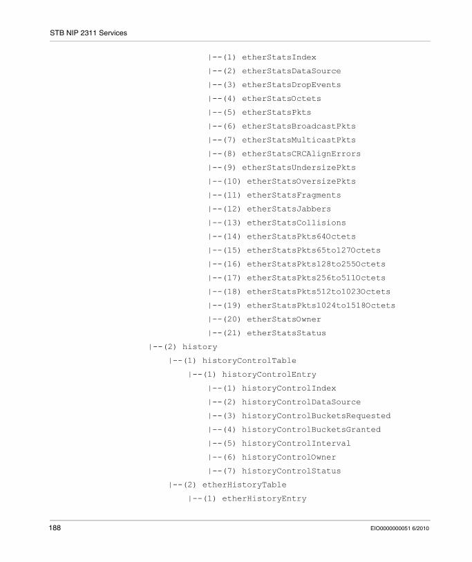
STB NIP 2311 Services
|--(1) etherStatsIndex
|--(2) etherStatsDataSource
|--(3) etherStatsDropEvents
|--(4) etherStatsOctets
|--(5) etherStatsPkts
|--(6) etherStatsBroadcastPkts
|--(7) etherStatsMulticastPkts
|--(8) etherStatsCRCAlignErrors
|--(9) etherStatsUndersizePkts
|--(10) etherStatsOversizePkts
|--(11) etherStatsFragments
|--(12) etherStatsJabbers
|--(13) etherStatsCollisions
|--(14) etherStatsPkts64Octets
|--(15) etherStatsPkts65to127Octets
|--(16) etherStatsPkts128to255Octets
|--(17) etherStatsPkts256to511Octets
|--(18) etherStatsPkts512to1023Octets
|--(19) etherStatsPkts1024to1518Octets
|--(20) etherStatsOwner
|--(21) etherStatsStatus
|--(2) history
|--(1) historyControlTable
|--(1) historyControlEntry
|--(1) historyControlIndex
|--(2) historyControlDataSource
|--(3) historyControlBucketsRequested
|--(4) historyControlBucketsGranted
|--(5) historyControlInterval
|--(6) historyControlOwner
|--(7) historyControlStatus
|--(2) etherHistoryTable
|--(1) etherHistoryEntry
188 EIO0000000051 6/2010
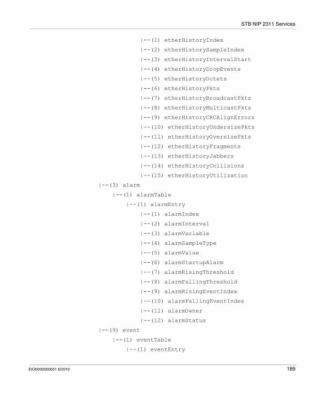
STB NIP 2311 Services
|--(1) etherHistoryIndex
|--(2) etherHistorySampleIndex
|--(3) etherHistoryIntervalStart
|--(4) etherHistoryDropEvents
|--(5) etherHistoryOctets
|--(6) etherHistoryPkts
|--(7) etherHistoryBroadcastPkts
|--(8) etherHistoryMulticastPkts
|--(9) etherHistoryCRCAlignErrors
|--(10) etherHistoryUndersizePkts
|--(11) etherHistoryOversizePkts
|--(12) etherHistoryFragments
|--(13) etherHistoryJabbers
|--(14) etherHistoryCollisions
|--(15) etherHistoryUtilization
|--(3) alarm
|--(1) alarmTable
|--(1) alarmEntry
|--(1) alarmIndex
|--(2) alarmInterval
|--(3) alarmVariable
|--(4) alarmSampleType
|--(5) alarmValue
|--(6) alarmStartupAlarm
|--(7) alarmRisingThreshold
|--(8) alarmFallingThreshold
|--(9) alarmRisingEventIndex
|--(10) alarmFallingEventIndex
|--(11) alarmOwner
|--(12) alarmStatus
|--(9) event
|--(1) eventTable
|--(1) eventEntry
EIO0000000051 6/2010 189

STB NIP 2311 Services
|--(1) eventIndex
|--(2) eventDescription
|--(3) eventType
|--(4) eventCommunity
|--(5) eventLastTimeSent
|--(6) eventOwner
|--(7) eventStatus
|--(2) logTable
|--(1) logEntry(1)
|--(1) logEventIndex
|--(2) logIndex
|--(3) logTime
|--(4) logDescription
|--(19) probeConfig
|--(15) smonCapabilities
|--(22) switchRMON
|--(1) smonMIBObjects
|--(1) dataSourceCaps
|--(1) dataSourceCapsTable
|--(1) dataSourceCapsEntry
|--(1) dataSourceCapsObject
|--(2) dataSourceRmonCaps
|--(3) dataSourceCopyCaps
|--(4) dataSourceCapsIfIndex
|--(3) portCopyConfig
|--(1) portCopyTable
|--(1) portCopyEntry
|--(1) portCopySource
|--(2) portCopyDest
|--(3) portCopyDestDropEvents
|--(4) portCopyDirection
|--(5) portCopyStatus
190 EIO0000000051 6/2010
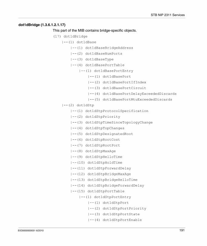
STB NIP 2311 Services
dot1dBridge (1.3.6.1.2.1.17)
This part of the MIB contains bridge-specific objects.
(17) dot1dBridge
|--(1) dot1dBase
|--(1) dot1dBaseBridgeAddress
|--(2) dot1dBaseNumPorts
|--(3) dot1dBaseType
|--(4) dot1dBasePortTable
|--(1) dot1dBasePortEntry
|--(1) dot1dBasePort
|--(2) dot1dBasePortIfIndex
|--(3) dot1dBasePortCircuit
|--(4) dot1dBasePortDelayExceededDiscards
|--(5) dot1dBasePortMtuExceededDiscards
|--(2) dot1dStp
|--(1) dot1dStpProtocolSpecification
|--(2) dot1dStpPriority
|--(3) dot1dStpTimeSinceTopologyChange
|--(4) dot1dStpTopChanges
|--(5) dot1dStpDesignatedRoot
|--(6) dot1dStpRootCost
|--(7) dot1dStpRootPort
|--(8) dot1dStpMaxAge
|--(9) dot1dStpHelloTime
|--(10) dot1dStpHoldTime
|--(11) dot1dStpForwardDelay
|--(12) dot1dStpBridgeMaxAge
|--(13) dot1dStpBridgeHelloTime
|--(14) dot1dStpBridgeForwardDelay
|--(15) dot1dStpPortTable
|--(1) dot1dStpPortEntry
|--(1) dot1dStpPort
|--(2) dot1dStpPortPriority
|--(3) dot1dStpPortState
|--(4) dot1dStpPortEnable
EIO0000000051 6/2010 191
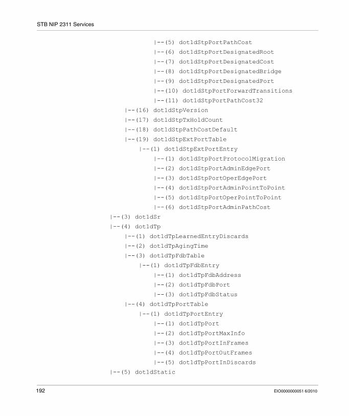
STB NIP 2311 Services
|--(5) dot1dStpPortPathCost
|--(6) dot1dStpPortDesignatedRoot
|--(7) dot1dStpPortDesignatedCost
|--(8) dot1dStpPortDesignatedBridge
|--(9) dot1dStpPortDesignatedPort
|--(10) dot1dStpPortForwardTransitions
|--(11) dot1dStpPortPathCost32
|--(16) dot1dStpVersion
|--(17) dot1dStpTxHoldCount
|--(18) dot1dStpPathCostDefault
|--(19) dot1dStpExtPortTable
|--(1) dot1dStpExtPortEntry
|--(1) dot1dStpPortProtocolMigration
|--(2) dot1dStpPortAdminEdgePort
|--(3) dot1dStpPortOperEdgePort
|--(4) dot1dStpPortAdminPointToPoint
|--(5) dot1dStpPortOperPointToPoint
|--(6) dot1dStpPortAdminPathCost
|--(3) dot1dSr
|--(4) dot1dTp
|--(1) dot1dTpLearnedEntryDiscards
|--(2) dot1dTpAgingTime
|--(3) dot1dTpFdbTable
|--(1) dot1dTpFdbEntry
|--(1) dot1dTpFdbAddress
|--(2) dot1dTpFdbPort
|--(3) dot1dTpFdbStatus
|--(4) dot1dTpPortTable
|--(1) dot1dTpPortEntry
|--(1) dot1dTpPort
|--(2) dot1dTpPortMaxInfo
|--(3) dot1dTpPortInFrames
|--(4) dot1dTpPortOutFrames
|--(5) dot1dTpPortInDiscards
|--(5) dot1dStatic
192 EIO0000000051 6/2010
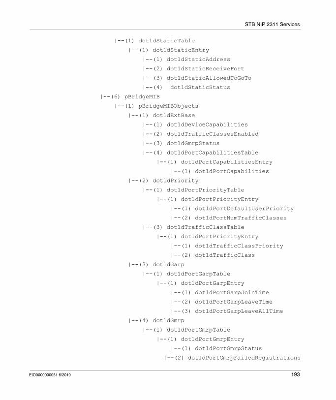
STB NIP 2311 Services
|--(1) dot1dStaticTable
|--(1) dot1dStaticEntry
|--(1) dot1dStaticAddress
|--(2) dot1dStaticReceivePort
|--(3) dot1dStaticAllowedToGoTo
|--(4) dot1dStaticStatus
|--(6) pBridgeMIB
|--(1) pBridgeMIBObjects
|--(1) dot1dExtBase
|--(1) dot1dDeviceCapabilities
|--(2) dot1dTrafficClassesEnabled
|--(3) dot1dGmrpStatus
|--(4) dot1dPortCapabilitiesTable
|--(1) dot1dPortCapabilitiesEntry
|--(1) dot1dPortCapabilities
|--(2) dot1dPriority
|--(1) dot1dPortPriorityTable
|--(1) dot1dPortPriorityEntry
|--(1) dot1dPortDefaultUserPriority
|--(2) dot1dPortNumTrafficClasses
|--(3) dot1dTrafficClassTable
|--(1) dot1dPortPriorityEntry
|--(1) dot1dTrafficClassPriority
|--(2) dot1dTrafficClass
|--(3) dot1dGarp
|--(1) dot1dPortGarpTable
|--(1) dot1dPortGarpEntry
|--(1) dot1dPortGarpJoinTime
|--(2) dot1dPortGarpLeaveTime
|--(3) dot1dPortGarpLeaveAllTime
|--(4) dot1dGmrp
|--(1) dot1dPortGmrpTable
|--(1) dot1dPortGmrpEntry
|--(1) dot1dPortGmrpStatus
|--(2) dot1dPortGmrpFailedRegistrations
EIO0000000051 6/2010 193
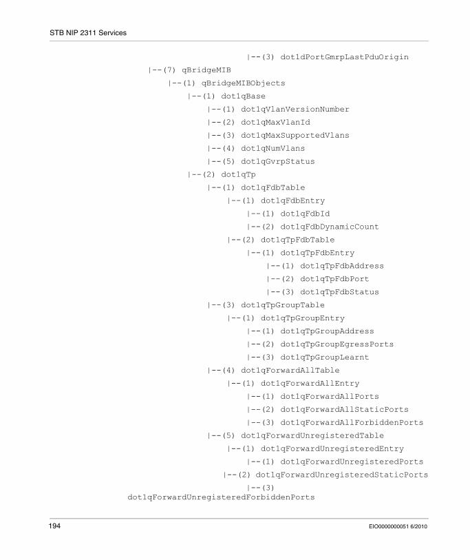
STB NIP 2311 Services
|--(3) dot1dPortGmrpLastPduOrigin
|--(7) qBridgeMIB
|--(1) qBridgeMIBObjects
|--(1) dot1qBase
|--(1) dot1qVlanVersionNumber
|--(2) dot1qMaxVlanId
|--(3) dot1qMaxSupportedVlans
|--(4) dot1qNumVlans
|--(5) dot1qGvrpStatus
|--(2) dot1qTp
|--(1) dot1qFdbTable
|--(1) dot1qFdbEntry
|--(1) dot1qFdbId
|--(2) dot1qFdbDynamicCount
|--(2) dot1qTpFdbTable
|--(1) dot1qTpFdbEntry
|--(1) dot1qTpFdbAddress
|--(2) dot1qTpFdbPort
|--(3) dot1qTpFdbStatus
|--(3) dot1qTpGroupTable
|--(1) dot1qTpGroupEntry
|--(1) dot1qTpGroupAddress
|--(2) dot1qTpGroupEgressPorts
|--(3) dot1qTpGroupLearnt
|--(4) dot1qForwardAllTable
|--(1) dot1qForwardAllEntry
|--(1) dot1qForwardAllPorts
|--(2) dot1qForwardAllStaticPorts
|--(3) dot1qForwardAllForbiddenPorts
|--(5) dot1qForwardUnregisteredTable
|--(1) dot1qForwardUnregisteredEntry
|--(1) dot1qForwardUnregisteredPorts
|--(2) dot1qForwardUnregisteredStaticPorts
|--(3) dot1qForwardUnregisteredForbiddenPorts
194 EIO0000000051 6/2010
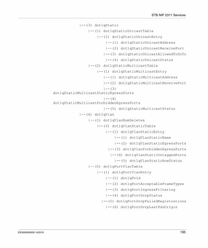
STB NIP 2311 Services
|--(3) dot1qStatic
|--(1) dot1qStaticUnicastTable
|--(1) dot1qStaticUnicastEntry
|--(1) dot1qStaticUnicastAddress
|--(2) dot1qStaticUnicastReceivePort
|--(3) dot1qStaticUnicastAllowedToGoTo
|--(4) dot1qStaticUnicastStatus
|--(2) dot1qStaticMulticastTable
|--(1) dot1qStaticMulticastEntry
|--(1) dot1qStaticMulticastAddress
|--(2) dot1qStaticMulticastReceivePort
|--(3) dot1qStaticMulticastStaticEgressPorts
|--(4) dot1qStaticMulticastForbiddenEgressPorts
|--(5) dot1qStaticMulticastStatus
|--(4) dot1qVlan
|--(1) dot1qVlanNumDeletes
|--(3) dot1qVlanStaticTable
|--(1) dot1qVlanStaticEntry
|--(1) dot1qVlanStaticName
|--(2) dot1qVlanStaticEgressPorts
|--(3) dot1qVlanForbiddenEgressPorts
|--(4) dot1qVlanStaticUntaggedPorts
|--(5) dot1qVlanStaticRowStatus
|--(5) dot1qPortVlanTable
|--(1) dot1qPortVlanEntry
|--(1) dot1qPvid
|--(2) dot1qPortAcceptableFrameTypes
|--(3) dot1qPortIngressFiltering
|--(4) dot1qPortGvrpStatus
|--(5) dot1qPortGvrpFailedRegistrations
|--(6) dot1qPortGvrpLastPduOrigin
EIO0000000051 6/2010 195
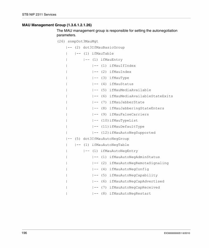
STB NIP 2311 Services
MAU Management Group (1.3.6.1.2.1.26)
The MAU management group is responsible for setting the autonegotiation parameters.
(26) snmpDot3MauMgt
|-- (2) dot3IfMauBasicGroup
| |-- (1) ifMauTable
| |-- (1) ifMauEntry
| |-- (1) ifMauIfIndex
| |-- (2) ifMauIndex
| |-- (3) ifMauType
| |-- (4) ifMauStatus
| |-- (5) ifMauMediaAvailable
| |-- (6) ifMauMediaAvailableStateExits
| |-- (7) ifMauJabberState
| |-- (8) ifMauJabberingStateEnters
| |-- (9) ifMauFalseCarriers
| |-- (10)ifMauTypeList
| |-- (11)ifMauDefaultType
| |-- (12)ifMauAutoNegSupported
|-- (5) dot3IfMauAutoNegGroup
| |-- (1) ifMauAutoNegTable
| |-- (1) ifMauAutoNegEntry
| |-- (1) ifMauAutoNegAdminStatus
| |-- (2) ifMauAutoNegRemoteSignaling
| |-- (4) ifMauAutoNegConfig
| |-- (5) ifMauAutoNegCapability
| |-- (6) ifMauAutoNegCapAdvertised
| |-- (7) ifMauAutoNegCapReceived
| |-- (8) ifMauAutoNegRestart
196 EIO0000000051 6/2010
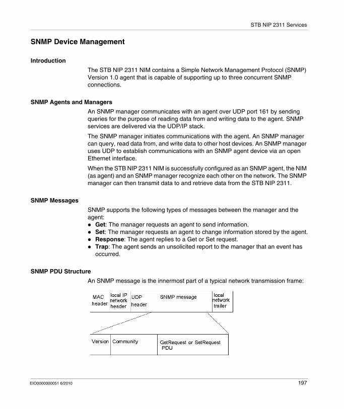
STB NIP 2311 Services
SNMP Device Management
Introduction
The STB NIP 2311 NIM contains a Simple Network Management Protocol (SNMP) Version 1.0 agent that is capable of supporting up to three concurrent SNMP connections.
SNMP Agents and Managers
An SNMP manager communicates with an agent over UDP port 161 by sending queries for the purpose of reading data from and writing data to the agent. SNMP services are delivered via the UDP/IP stack.
The SNMP manager initiates communications with the agent. An SNMP manager can query, read data from, and write data to other host devices. An SNMP manager uses UDP to establish communications with an SNMP agent device via an open Ethernet interface.
When the STB NIP 2311 NIM is successfully configured as an SNMP agent, the NIM (as agent) and an SNMP manager recognize each other on the network. The SNMP manager can then transmit data to and retrieve data from the STB NIP 2311.
SNMP Messages
SNMP supports the following types of messages between the manager and the agent:
Get: The manager requests an agent to send information.Set: The manager requests an agent to change information stored by the agent.Response: The agent replies to a Get or Set request.Trap: The agent sends an unsolicited report to the manager that an event has occurred.
SNMP PDU Structure
An SNMP message is the innermost part of a typical network transmission frame:
EIO0000000051 6/2010 197
STB NIP 2311 Services
Trap Reporting
A trap is an agent-detected event sent over UDP port 162 that indicates either:a change has occurred in the status of the agent, oran unauthorized manager device has attempted to get data from, or change data on, the agent
You can configure the STB NIP 2311 NIM to report traps to one or two authorized SNMP managers. You can also enable or disable specific traps.
Authorizing Access
SNMP uses community names to limit unauthorized access to the STB NIP 2311 NIM configuration settings and trap notifications. A community name acts as a password. Each type of communication (Get, Set, and Trap) can be separately configured with its own password.
The manager and the agent must both be configured with the same password before:
the agent can accept Get or Set requests from the manager, andthe manager can accept trap notifications from the agent
NOTE: If you do not configure private community names for Get and Set requests, any SNMP manager can read the execute these commands against the parameters in your STB NIP 2311 NIM.
198 EIO0000000051 6/2010
STB NIP 2311 Services
Configuring the SNMP Agent
Description
The STB NIP 2311 module’s SNMP agent service can be configured using either:the SNMP Agent Configuration web page (see page 162), orthe SNMP Agent tab (see page 66) on the Ethernet Parameters dialog box in the Advantys Configuration Software
EIO0000000051 6/2010 199
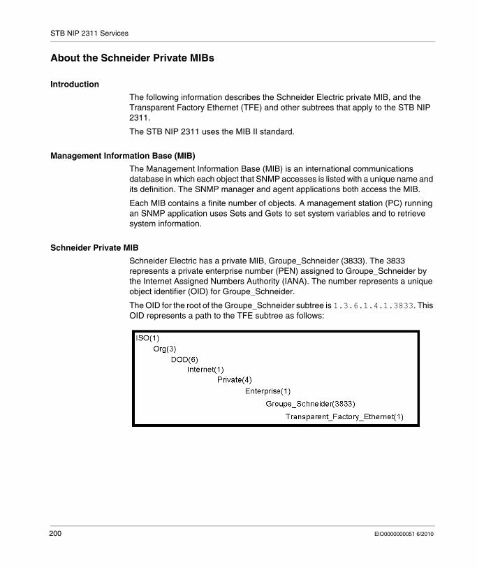
STB NIP 2311 Services
About the Schneider Private MIBs
Introduction
The following information describes the Schneider Electric private MIB, and the Transparent Factory Ethernet (TFE) and other subtrees that apply to the STB NIP 2311.
The STB NIP 2311 uses the MIB II standard.
Management Information Base (MIB)
The Management Information Base (MIB) is an international communications database in which each object that SNMP accesses is listed with a unique name and its definition. The SNMP manager and agent applications both access the MIB.
Each MIB contains a finite number of objects. A management station (PC) running an SNMP application uses Sets and Gets to set system variables and to retrieve system information.
Schneider Private MIB
Schneider Electric has a private MIB, Groupe_Schneider (3833). The 3833 represents a private enterprise number (PEN) assigned to Groupe_Schneider by the Internet Assigned Numbers Authority (IANA). The number represents a unique object identifier (OID) for Groupe_Schneider.
The OID for the root of the Groupe_Schneider subtree is 1.3.6.1.4.1.3833. This OID represents a path to the TFE subtree as follows:
200 EIO0000000051 6/2010
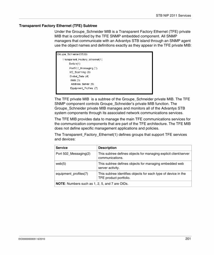
STB NIP 2311 Services
Transparent Factory Ethernet (TFE) Subtree
Under the Groupe_Schneider MIB is a Transparent Factory Ethernet (TFE) private MIB that is controlled by the TFE SNMP embedded component. All SNMP managers that communicate with an Advantys STB island through an SNMP agent use the object names and definitions exactly as they appear in the TFE private MIB:
The TFE private MIB is a subtree of the Groupe_Schneider private MIB. The TFE SNMP component controls Groupe_Schneider’s private MIB function. The Groupe_Schneider private MIB manages and monitors all of the Advantys STB system components through its associated network communications services.
The TFE MIB provides data to manage the main TFE communications services for the communication components that are part of the TFE architecture. The TFE MIB does not define specific management applications and policies.
The Transparent_Factory_Ethernet(1) defines groups that support TFE services and devices:
Service Description
Port 502_Messaging(2) This subtree defines objects for managing explicit client/server communications.
web(5) This subtree defines objects for managing embedded web server activity.
equipment_profiles(7) This subtree identifies objects for each type of device in the TFE product portfolio.
NOTE: Numbers such as 1, 2, 5, and 7 are OIDs.
EIO0000000051 6/2010 201
STB NIP 2311 Services
MIB Subtree Description
Transparent Factory Ethernet Subtree
This topic details some of the objects in the Schneider private MIB tree. The transparentFactoryEthernet(1) subtree defines groups that support the TFE services and devices:
NOTE: All listed services are not available on all communications modules. Refer to the available services for your module.
When devices are added to the Schneider catalog, the private MIB is extended in the following manner:
If needed, a Transparent Factory communication-service object is added for the new device in the subtree that corresponds to equipmentProfile(7). This subtree can hold as many objects as are required.If needed, a new branch is added at the same level as transparentFactory-Ethernet(1). This subtree is created for product-specific objects.
When a new device is added to the catalog a corresponding object description is created in the ASN.1 format. The ASN.1 file(s) are then given to producers of SNMP manager software for inclusion in their products.
Service Subtree Definition
switch(1) the brand of switches labeled
port502Messaging(2) (see page 203)
objects for managing explicit client/server communications to support applications (for example, HMI, SCADA, or programming tools)
ioScanning(3) objects for managing I/O device communications that use the I/O Scanner with the Modbus/TCP protocol
globalData(4) objects for managing the application coordination service using a publish/subscribe protocol
web(5) (see page 204) objects for managing the activity of the embedded Web servers
addressServer(6) objects for managing the activity of the BOOTP or DHCP servers
equipmentProfile(7) objects for each device type in Transparent Factory Ethernet product portfolio
timeManagement(8) (NTP) objects for managing the UTC time stamp service
email(9) (SMTP) objects for managing the email service
tfeMibVersion(255) the version of the Schneider TFE MIB supported by the product
202 EIO0000000051 6/2010
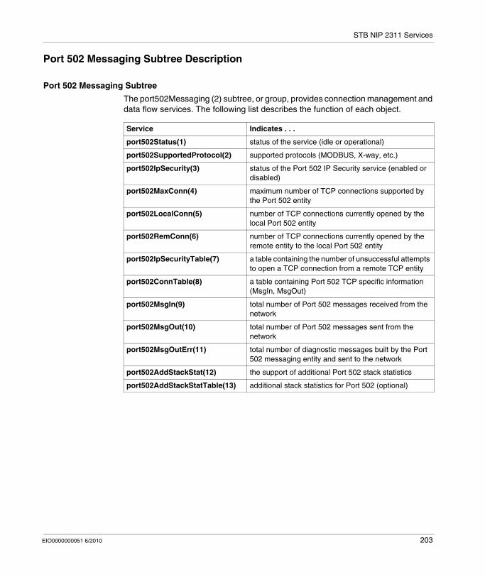
STB NIP 2311 Services
Port 502 Messaging Subtree Description
Port 502 Messaging Subtree
The port502Messaging (2) subtree, or group, provides connection management and data flow services. The following list describes the function of each object.
Service Indicates . . .
port502Status(1) status of the service (idle or operational)
port502SupportedProtocol(2) supported protocols (MODBUS, X-way, etc.)
port502IpSecurity(3) status of the Port 502 IP Security service (enabled or disabled)
port502MaxConn(4) maximum number of TCP connections supported by the Port 502 entity
port502LocalConn(5) number of TCP connections currently opened by the local Port 502 entity
port502RemConn(6) number of TCP connections currently opened by the remote entity to the local Port 502 entity
port502IpSecurityTable(7) a table containing the number of unsuccessful attempts to open a TCP connection from a remote TCP entity
port502ConnTable(8) a table containing Port 502 TCP specific information (MsgIn, MsgOut)
port502MsgIn(9) total number of Port 502 messages received from the network
port502MsgOut(10) total number of Port 502 messages sent from the network
port502MsgOutErr(11) total number of diagnostic messages built by the Port 502 messaging entity and sent to the network
port502AddStackStat(12) the support of additional Port 502 stack statistics
port502AddStackStatTable(13) additional stack statistics for Port 502 (optional)
EIO0000000051 6/2010 203
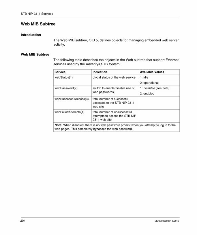
STB NIP 2311 Services
Web MIB Subtree
Introduction
The Web MIB subtree, OID 5, defines objects for managing embedded web server activity.
Web MIB Subtree
The following table describes the objects in the Web subtree that support Ethernet services used by the Advantys STB system:
Service Indication Available Values
webStatus(1) global status of the web service 1: idle
2: operational
webPassword(2) switch to enable/disable use of web passwords
1: disabled (see note)
2: enabled
webSuccessfulAccess(3) total number of successful accesses to the STB NIP 2311 web site
webFailedAttempts(4) total number of unsuccessful attempts to access the STB NIP 2311 web site
Note: When disabled, there is no web password prompt when you attempt to log in to the web pages. This completely bypasses the web password.
204 EIO0000000051 6/2010
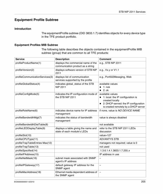
STB NIP 2311 Services
Equipment Profile Subtree
Introduction
The equipmentProfile subtree (OID 3833.1.7) identifies objects for every device type in the TFE product portfolio.
Equipment Profiles MIB Subtree
The following table describes the objects contained in the equipmentProfile MIB subtree (group) that are common to all TFE products:
Service Description Comment
profileProductName(1) displays the commercial name of the communication product as a string
e.g., STB NIP 2311
profileVersion(2) displays software version of STB NIP 2311
e.g., Vx.y or V1.1
profileCommunicationServices(3) displays list of communication services supported by the profile
e.g., Port502Messging, Web
profileGlobalStatus(4) indicates global_status of the STB NIP 2311
available values1: nok2: ok
profileConfigMode(5) indicates the IP configuration mode of the STB NIP 2311
available values1: local: the IP configuration is created locally2: DHCP-served: the IP configuration is created remotely by a DHCP server
profileRoleName(6) indicates device name for IP address management
if none, value is NO DEVICE NAME
profileBandwidthMgt(7) indicates the status of bandwidth management
value is always disabled
profileBandwidthDistTable(8) not available
profileLEDDisplayTable(9) displays a table giving the name and state of each module’s LEDs
refer to the STB NIP 2311 LEDs discussion
profileSlot(10) value=127
profileCPUType(11) ADVANTYS STB
profileTrapTableEntries Max(12) managers not required; value is 0
profileTrapTable(13) not used
profileSpecified(14) .1.3.6.1.4.1.3833.1.7.255.x
profileIPAddress(15) IP address in use
profileNetMask(16) subnet mask associated with SNMP agent’s IP address
–
profileIPGateway(17) default gateway IP address for the SNMP agent
–
profileMacAddress(18) Ethernet media dependent address of the SNMP agent
–
EIO0000000051 6/2010 205

STB NIP 2311 Services
206 EIO0000000051 6/2010

EIO0000000051 6/2010
8
Connecting an Advantys STB Island to a Quantum Master Using Unity Pro
EIO0000000051 6/2010
Connecting an Advantys STB Island to a Quantum Master Using Unity Pro
At a Glance
In this chapter, we use Unity Pro to establish Ethernet communications between the NOE 771 11 communications module in a Quantum PLC rack and an Advantys island with an STB NIP 2311 NIM.
NOTE: The steps can also be used to establish communications between the same Advantys island (with an STB NIP 2311 NIM) and either a Unity Premium PLC or a Unity M340 PLC.
What's in this Chapter?
This chapter contains the following topics:
Topic Page
About This Connection Example 208
How to Configure Unity Pro to Use Advantys Island I/O Data 211
How to Set Up RTP and HMI to PLC Communications 219
How to Enable RSTP 222
How to Store an Island Configuration in a Removable Memory Card 224
207
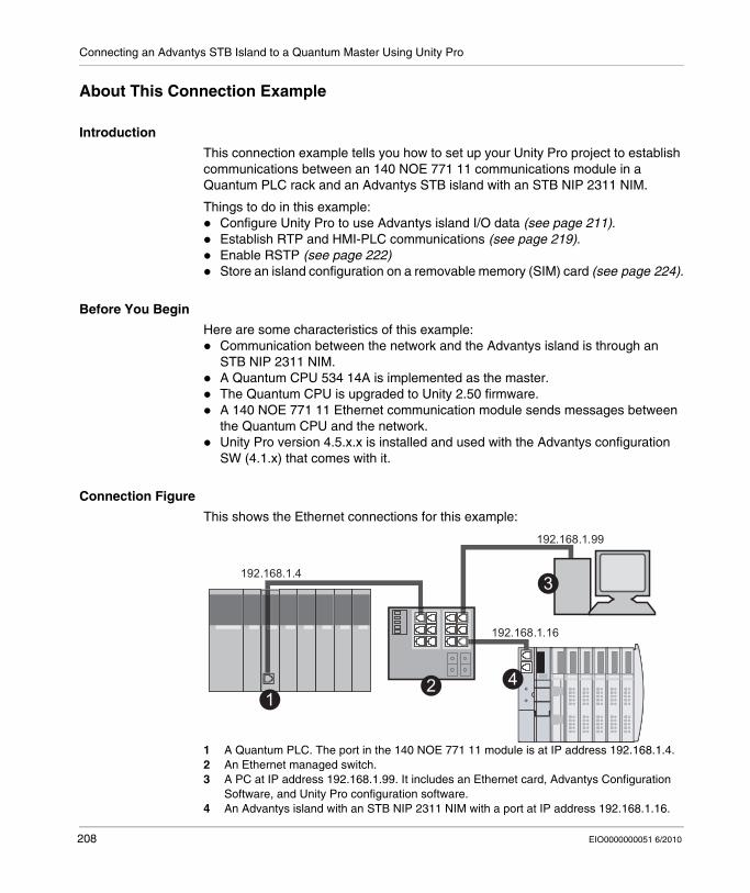
Connecting an Advantys STB Island to a Quantum Master Using Unity Pro
About This Connection Example
Introduction
This connection example tells you how to set up your Unity Pro project to establish communications between an 140 NOE 771 11 communications module in a Quantum PLC rack and an Advantys STB island with an STB NIP 2311 NIM.
Things to do in this example:Configure Unity Pro to use Advantys island I/O data (see page 211).Establish RTP and HMI-PLC communications (see page 219).Enable RSTP (see page 222)Store an island configuration on a removable memory (SIM) card (see page 224).
Before You Begin
Here are some characteristics of this example:Communication between the network and the Advantys island is through an STB NIP 2311 NIM.A Quantum CPU 534 14A is implemented as the master.The Quantum CPU is upgraded to Unity 2.50 firmware.A 140 NOE 771 11 Ethernet communication module sends messages between the Quantum CPU and the network.Unity Pro version 4.5.x.x is installed and used with the Advantys configuration SW (4.1.x) that comes with it.
Connection Figure
This shows the Ethernet connections for this example:
1 A Quantum PLC. The port in the 140 NOE 771 11 module is at IP address 192.168.1.4.2 An Ethernet managed switch.3 A PC at IP address 192.168.1.99. It includes an Ethernet card, Advantys Configuration
Software, and Unity Pro configuration software.4 An Advantys island with an STB NIP 2311 NIM with a port at IP address 192.168.1.16.
208 EIO0000000051 6/2010
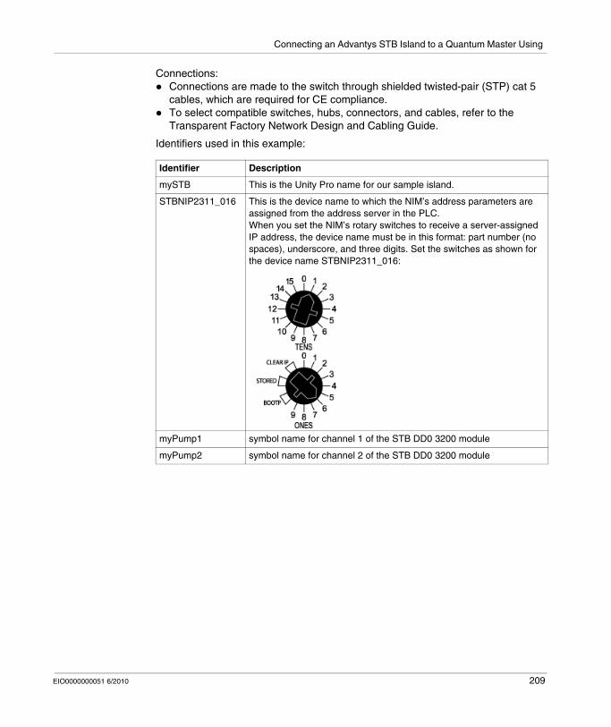
Connecting an Advantys STB Island to a Quantum Master Using
Connections:Connections are made to the switch through shielded twisted-pair (STP) cat 5 cables, which are required for CE compliance.To select compatible switches, hubs, connectors, and cables, refer to the Transparent Factory Network Design and Cabling Guide.
Identifiers used in this example:
Identifier Description
mySTB This is the Unity Pro name for our sample island.
STBNIP2311_016 This is the device name to which the NIM’s address parameters are assigned from the address server in the PLC.When you set the NIM’s rotary switches to receive a server-assigned IP address, the device name must be in this format: part number (no spaces), underscore, and three digits. Set the switches as shown for the device name STBNIP2311_016:
myPump1 symbol name for channel 1 of the STB DD0 3200 module
myPump2 symbol name for channel 2 of the STB DD0 3200 module
EIO0000000051 6/2010 209

Connecting an Advantys STB Island to a Quantum Master Using Unity Pro
Sample Island
This sample island is used in the connection example. It is a representative island bus assembly with an STB NIP 2311 NIM:
1 STB NIP 2311 NIM: network interface module2 STB PDT 3100: 24 VDC power distribution module (PDM)3 STB DDI 3230: 24 VDC 2-channel digital input module (2 bits data, 2 bits status)4 STB DDO 3200: 24 VDC 2-channel digital output module (2 bits data, 2 bits of echo output
data, 2 bits status)5 STB DDI 3420: 24 VDC 4-channel digital input module (4 bits data, 4 bits status)6 STB DDO 3410: 24 VDC 4-channel digital output module (4 bits data, 4 bits of echo output
data, 4 bits status)7 STB DDI 3610: 24 VDC 6-channel digital input module (6 bits data, 6 bits status)8 STB DDO 3600: 24 VDC 6-channel digital output module (6 bits data, 6 bits of echo output
data, 6 bits status)9 STB AVI 1270: +/-10 VDC 2-channel analog input module (16 bits data–channel 1, 16 bits
data–channel 2, 8 bits status–channel 1, 8 bits status–channel 2)10 STB AVO 1250: +/-10 VDC 2-channel analog output module (16 bits data–channel 1,
16 bits data–channel 2, 8 bits status–channel 1, 8 bits status–channel 2)11 STB XMP 1100: island bus termination plate
The I/O modules in the sample assembly have the following island bus addresses:
NOTE: The PDM and the termination plate are not addressable (see page 44).
I/O Model Module Type Module’s Island Bus AddressSTB DDI 3230 2-channel digital input 1STB DDO 3200 2-channel digital output 2STB DDI 3420 4-channel digital input 3STB DDO 3410 4-channel digital output 4STB DDI 3610 6-channel digital input 5STB DDO 3600 6-channel digital output 6STB AVI 1270 2-channel analog input 7STB AVO 1250 2-channel analog output 8
1 2 3 5 116 74 8 9 10
210 EIO0000000051 6/2010

Connecting an Advantys STB Island to a Quantum Master Using
How to Configure Unity Pro to Use Advantys Island I/O Data
Introduction
Use these instructions to configure Unity Pro to use the input and output data of the Advantys island with an STB NIP NIM.
Create a Quantum Rack
Create a Quantum PLC rack for this example:
Create a New Network
Use these instructions to create a new network:
Step Action Comment
1 Open Unity Pro. You are asked to choose a processor.
2 Select File → New. The New Project dialog box appears.
3 Expand the Quantum menu. Click the plus (+) sign next to Quantum.
4 Double-click on 140 CPU 534 14A.
5 Select Local Bus to see the rack. The processor is shown in slot 2 on the PLC rack.
6 Double-click slot 3. The next module you select will occupy slot 3.
7 Expand the Communications menu. Click the plus (+) sign next to Communications.
8 Double-click on 140 NOE 771 11. The Ethernet communications module appears in slot 3.
9 Double-click slot 1. The next module you select will occupy slot 1.
10 Expand the Supply menu. Click the plus (+) sign next to Supply.
11 Double-click on 140 CPU 111 00. The CPU appears in slot 1.
Step Action Comment
1 Expand the Communications menu.
In the Project Browser, click the plus (+) sign next to Communications.
2 Select Networks → New Network.
The Add Network dialog box appears.
3 Select List of Available Networks → Ethernet.
For this example, you accept the default network name (Ethernet_1) in the Change Name field.
4 Press OK.
EIO0000000051 6/2010 211
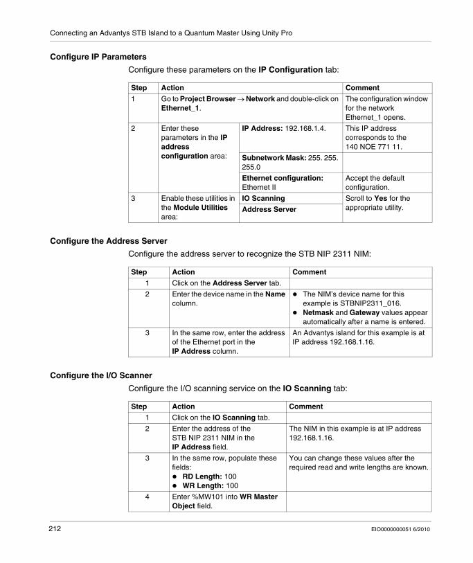
Connecting an Advantys STB Island to a Quantum Master Using Unity Pro
Configure IP Parameters
Configure these parameters on the IP Configuration tab:
Configure the Address Server
Configure the address server to recognize the STB NIP 2311 NIM:
Configure the I/O Scanner
Configure the I/O scanning service on the IO Scanning tab:
Step Action Comment
1 Go to Project Browser → Network and double-click on Ethernet_1.
The configuration window for the network Ethernet_1 opens.
2 Enter these parameters in the IP address configuration area:
IP Address: 192.168.1.4. This IP address corresponds to the 140 NOE 771 11.
Subnetwork Mask: 255. 255. 255.0
Ethernet configuration: Ethernet II
Accept the default configuration.
3 Enable these utilities in the Module Utilities area:
IO Scanning Scroll to Yes for the appropriate utility.Address Server
Step Action Comment
1 Click on the Address Server tab.
2 Enter the device name in the Name column.
The NIM’s device name for this example is STBNIP2311_016.Netmask and Gateway values appear automatically after a name is entered.
3 In the same row, enter the address of the Ethernet port in the IP Address column.
An Advantys island for this example is at IP address 192.168.1.16.
Step Action Comment
1 Click on the IO Scanning tab.
2 Enter the address of the STB NIP 2311 NIM in the IP Address field.
The NIM in this example is at IP address 192.168.1.16.
3 In the same row, populate these fields:
RD Length: 100WR Length: 100
You can change these values after the required read and write lengths are known.
4 Enter %MW101 into WR Master Object field.
212 EIO0000000051 6/2010

Connecting an Advantys STB Island to a Quantum Master Using
Launch the Advantys Configuration Software from Unity Pro
Assemble the Advantys Island
You can now assemble the island in the Advantys Configuration Software:
5 Click the Validate button in the toolbar.
The red arrow indicates the Validate button:
6 Select Device Type → STB.
7 In the Device Name field, enter mySTB.
8 Press OK. The Property dialog box opens.
9 Press Yes when Unity Pro asks you to confirm your Device Type and Device Name.
Step Action Comment
Step Action Comment
1 On Unity Pro’s IO Scanning tab, click the box (…) to the right of the Device Name field.
The Property dialog box appears.The Device Name (mySTB) is red.
2 Click the Launch Advantys Configuration Software button.
The Advantys Configuration Software opens.
Step Action Comment
1 In the Catalog Browser, expand the STB - Catalog folder.
Click the plus (+) sign next to STB -Catalog.
2 Expand the Networking tab and double-click on STBNIP2311 - V2.xx.
The STB NIP 2311 NIM appears in the island assembly.
3 Expand the Power tab and double-click on STBPDT3100 - V1.xx.
The STB PDT 3100 power module appears in the island assembly.
4 Expand the Digital Input, Digital Output, Analog Input, and Analog Output tabs to add the island I/O modules in the same manner.
Add these modules:STBDDI3230 - V1.xxSTBDDO3200 - V1.xxSTBDDI3420 - V1.xxSTBDDO3410 - V1.xxSTBDDI3610 - V1.xxSTBDDO3600 - V1.xxSTBAVI1270 - V1.xxSTBAVO1250 - V1.xx
5 Expand the Accessories tab and double-click on STBXMP1100 - V1.xx.
The STB XMP 1100 island bus termination plate appears in the island assembly.
EIO0000000051 6/2010 213
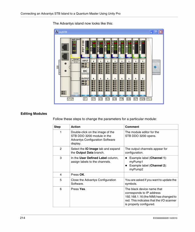
Connecting an Advantys STB Island to a Quantum Master Using Unity Pro
The Advantys island now looks like this:
Editing Modules
Follow these steps to change the parameters for a particular module:
Step Action Comment
1 Double-click on the image of the STB DDO 3200 module in the Advantys Configuration Software display.
The module editor for the STB DDO 3200 opens.
2 Select the IO Image tab and expand the Output Data branch.
The output channels appear for configuration.
3 In the User Defined Label column, assign labels to the channels.
Example label (Channel 1): myPump1Example label (Channel 2): myPump2
4 Press OK.
5 Close the Advantys Configuration Software.
You are asked if you want to update the symbols.
6 Press Yes. The black device name that corresponds to IP address 192.168.1.16 (the NIM) has changed to red. This indicates that the I/O scanner is properly configured.
214 EIO0000000051 6/2010
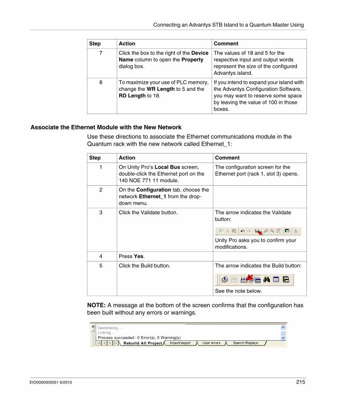
Connecting an Advantys STB Island to a Quantum Master Using
Associate the Ethernet Module with the New Network
Use these directions to associate the Ethernet communications module in the Quantum rack with the new network called Ethernet_1:
NOTE: A message at the bottom of the screen confirms that the configuration has been built without any errors or warnings.
7 Click the box to the right of the Device Name column to open the Property dialog box.
The values of 18 and 5 for the respective input and output words represent the size of the configured Advantys island.
8 To maximize your use of PLC memory, change the WR Length to 5 and the RD Length to 18.
If you intend to expand your island with the Advantys Configuration Software, you may want to reserve some space by leaving the value of 100 in those boxes.
Step Action Comment
Step Action Comment
1 On Unity Pro’s Local Bus screen, double-click the Ethernet port on the 140 NOE 771 11 module.
The configuration screen for the Ethernet port (rack 1, slot 3) opens.
2 On the Configuration tab, choose the network Ethernet_1 from the drop-down menu.
3 Click the Validate button. The arrow indicates the Validate button:
Unity Pro asks you to confirm your modifications.
4 Press Yes.
5 Click the Build button. The arrow indicates the Build button:
See the note below.
Linking...
Import/export User errors Search /ReplaceProcess succeeded : 0 Error(s) , 0 Warning(s)
Generating...
Rebuild All Project
EIO0000000051 6/2010 215
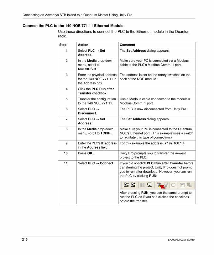
Connecting an Advantys STB Island to a Quantum Master Using Unity Pro
Connect the PLC to the 140 NOE 771 11 Ethernet Module
Use these directions to connect the PLC to the Ethernet module in the Quantum rack:
Step Action Comment
1 Select PLC → Set Address.
The Set Address dialog appears.
2 In the Media drop-down menu, scroll to MODBUS01.
Make sure your PC is connected via a Modbus cable to the PLC’s Modbus Comm. 1 port.
3 Enter the physical address for the 140 NOE 771 11 in the Address box.
The address is set on the rotary switches on the back of the NOE module.
4 Click the PLC Run after Transfer checkbox.
5 Transfer the configuration to the 140 NOE 771 11.
Use a Modbus cable connected to the module's Modbus Comm. 1 port.
6 Select PLC → Disconnect.
The PLC is now disconnected from Unity Pro.
7 Select PLC → Set Address.
The Set Address dialog appears.
8 In the Media drop-down menu, scroll to TCPIP.
Make sure your PC is connected to the Quantum NOE’s Ethernet port. (This example uses a switch to facilitate this type of connection.)
9 Enter the PLC’s IP address in the Address field.
For this example the address is 192.168.1.4.
10 Press OK. Unity Pro prompts you to transfer the newest project to the PLC.
11 Select PLC → Connect. If you did not click PLC Run after Transfer before transferring the project, Unity Pro does not prompt you to run after download. However, you can run the PLC by clicking RUN:
After pressing RUN, you see the same prompt to run the PLC as if you had clicked the checkbox before the transfer.
216 EIO0000000051 6/2010
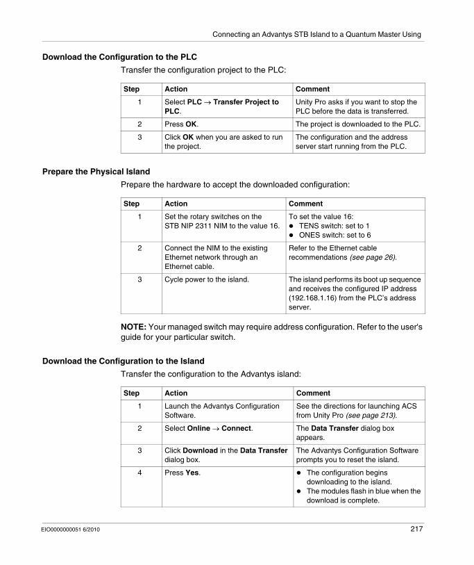
Connecting an Advantys STB Island to a Quantum Master Using
Download the Configuration to the PLC
Transfer the configuration project to the PLC:
Prepare the Physical Island
Prepare the hardware to accept the downloaded configuration:
NOTE: Your managed switch may require address configuration. Refer to the user's guide for your particular switch.
Download the Configuration to the Island
Transfer the configuration to the Advantys island:
Step Action Comment
1 Select PLC → Transfer Project to PLC.
Unity Pro asks if you want to stop the PLC before the data is transferred.
2 Press OK. The project is downloaded to the PLC.
3 Click OK when you are asked to run the project.
The configuration and the address server start running from the PLC.
Step Action Comment
1 Set the rotary switches on the STB NIP 2311 NIM to the value 16.
To set the value 16:TENS switch: set to 1ONES switch: set to 6
2 Connect the NIM to the existing Ethernet network through an Ethernet cable.
Refer to the Ethernet cable recommendations (see page 26).
3 Cycle power to the island. The island performs its boot up sequence and receives the configured IP address (192.168.1.16) from the PLC’s address server.
Step Action Comment
1 Launch the Advantys Configuration Software.
See the directions for launching ACS from Unity Pro (see page 213).
2 Select Online → Connect. The Data Transfer dialog box appears.
3 Click Download in the Data Transfer dialog box.
The Advantys Configuration Software prompts you to reset the island.
4 Press Yes. The configuration begins downloading to the island.The modules flash in blue when the download is complete.
EIO0000000051 6/2010 217
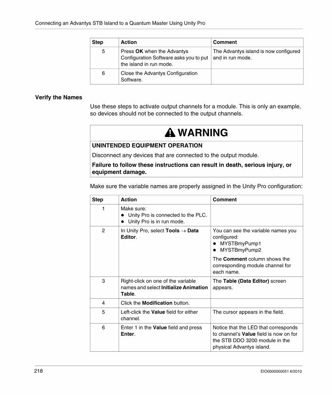
Connecting an Advantys STB Island to a Quantum Master Using Unity Pro
Verify the Names
Use these steps to activate output channels for a module. This is only an example, so devices should not be connected to the output channels.
Make sure the variable names are properly assigned in the Unity Pro configuration:
5 Press OK when the Advantys Configuration Software asks you to put the island in run mode.
The Advantys island is now configured and in run mode.
6 Close the Advantys Configuration Software.
Step Action Comment
WARNINGUNINTENDED EQUIPMENT OPERATION
Disconnect any devices that are connected to the output module.
Failure to follow these instructions can result in death, serious injury, or equipment damage.
Step Action Comment
1 Make sure:Unity Pro is connected to the PLC.Unity Pro is in run mode.
2 In Unity Pro, select Tools → Data Editor.
You can see the variable names you configured:
MYSTBmyPump1MYSTBmyPump2
The Comment column shows the corresponding module channel for each name.
3 Right-click on one of the variable names and select Initialize Animation Table.
The Table (Data Editor) screen appears.
4 Click the Modification button.
5 Left-click the Value field for either channel.
The cursor appears in the field.
6 Enter 1 in the Value field and press Enter.
Notice that the LED that corresponds to channel’s Value field is now on for the STB DDO 3200 module in the physical Advantys island.
218 EIO0000000051 6/2010
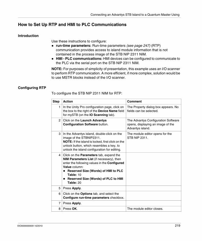
Connecting an Advantys STB Island to a Quantum Master Using
How to Set Up RTP and HMI to PLC Communications
Introduction
Use these instructions to configure:run-time parameters: Run-time parameters (see page 247) (RTP) communication provides access to island module information that is not contained in the process image of the STB NIP 2311 NIM.HMI - PLC communications: HMI devices can be configured to communicate to the PLC via the serial port on the STB NIP 2311 NIM.
NOTE: For purposes of simplicity of presentation, this example uses an I/O scanner to perform RTP communication. A more efficient, if more complex, solution would be to use MSTR blocks instead of the I/O scanner.
Configuring RTP
To configure the STB NIP 2311 NIM for RTP:
Step Action Comment
1 In the Unity Pro configuration page, click on the box to the right of the Device Name field for mySTB (on the IO Scanning tab).
The Property dialog box appears. No fields can be selected.
2 Click on the Launch Advantys Configuration Software button.
The Advantys Configuration Software opens, displaying an image of the Advantys island.
3 In the Advantys island, double-click on the image of the STBNIP2311.NOTE: If the island is locked, first click on the unlock button, which resembles a key, to unlock the island configuration for editing.
The module editor opens for the STB NIP 2311.
4 Click on the Parameters tab, expand the NIM Parameters List (if necessary), then enter the following values in the Configured Value column:
Reserved Size (Words) of HMI to PLC Table: 10Reserved Size (Words) of PLC to HMI Table: 20
5 Press Apply.
6 Click on the Options tab, and select the Configure run-time parameters checkbox.
7 Press Apply.
8 Press OK. The module editor closes.
EIO0000000051 6/2010 219
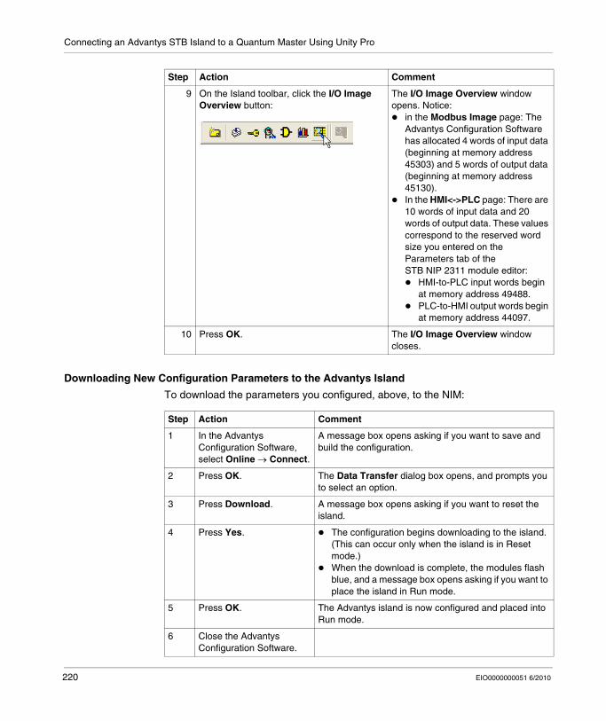
Connecting an Advantys STB Island to a Quantum Master Using Unity Pro
Downloading New Configuration Parameters to the Advantys Island
To download the parameters you configured, above, to the NIM:
9 On the Island toolbar, click the I/O Image Overview button:
The I/O Image Overview window opens. Notice:
in the Modbus Image page: The Advantys Configuration Software has allocated 4 words of input data (beginning at memory address 45303) and 5 words of output data (beginning at memory address 45130).In the HMI<->PLC page: There are 10 words of input data and 20 words of output data. These values correspond to the reserved word size you entered on the Parameters tab of the STB NIP 2311 module editor:
HMI-to-PLC input words begin at memory address 49488.PLC-to-HMI output words begin at memory address 44097.
10 Press OK. The I/O Image Overview window closes.
Step Action Comment
Step Action Comment
1 In the Advantys Configuration Software, select Online → Connect.
A message box opens asking if you want to save and build the configuration.
2 Press OK. The Data Transfer dialog box opens, and prompts you to select an option.
3 Press Download. A message box opens asking if you want to reset the island.
4 Press Yes. The configuration begins downloading to the island. (This can occur only when the island is in Reset mode.)When the download is complete, the modules flash blue, and a message box opens asking if you want to place the island in Run mode.
5 Press OK. The Advantys island is now configured and placed into Run mode.
6 Close the Advantys Configuration Software.
220 EIO0000000051 6/2010
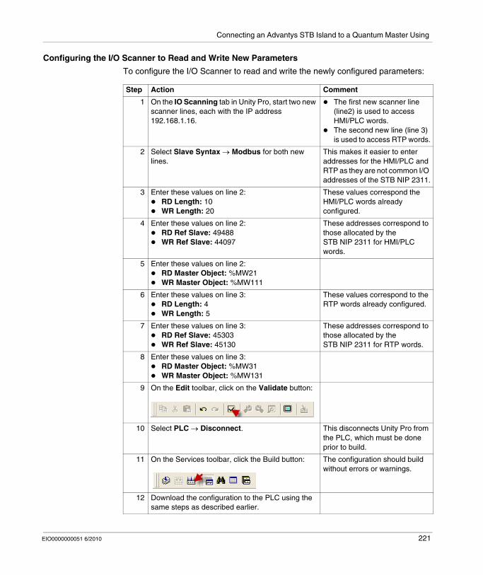
Connecting an Advantys STB Island to a Quantum Master Using
Configuring the I/O Scanner to Read and Write New Parameters
To configure the I/O Scanner to read and write the newly configured parameters:
Step Action Comment
1 On the IO Scanning tab in Unity Pro, start two new scanner lines, each with the IP address 192.168.1.16.
The first new scanner line (line2) is used to access HMI/PLC words.The second new line (line 3) is used to access RTP words.
2 Select Slave Syntax → Modbus for both new lines.
This makes it easier to enter addresses for the HMI/PLC and RTP as they are not common I/O addresses of the STB NIP 2311.
3 Enter these values on line 2:RD Length: 10WR Length: 20
These values correspond the HMI/PLC words already configured.
4 Enter these values on line 2:RD Ref Slave: 49488WR Ref Slave: 44097
These addresses correspond to those allocated by the STB NIP 2311 for HMI/PLC words.
5 Enter these values on line 2:RD Master Object: %MW21WR Master Object: %MW111
6 Enter these values on line 3:RD Length: 4WR Length: 5
These values correspond to the RTP words already configured.
7 Enter these values on line 3:RD Ref Slave: 45303WR Ref Slave: 45130
These addresses correspond to those allocated by the STB NIP 2311 for RTP words.
8 Enter these values on line 3:RD Master Object: %MW31WR Master Object: %MW131
9 On the Edit toolbar, click on the Validate button:
10 Select PLC → Disconnect. This disconnects Unity Pro from the PLC, which must be done prior to build.
11 On the Services toolbar, click the Build button: The configuration should build without errors or warnings.
12 Download the configuration to the PLC using the same steps as described earlier.
EIO0000000051 6/2010 221
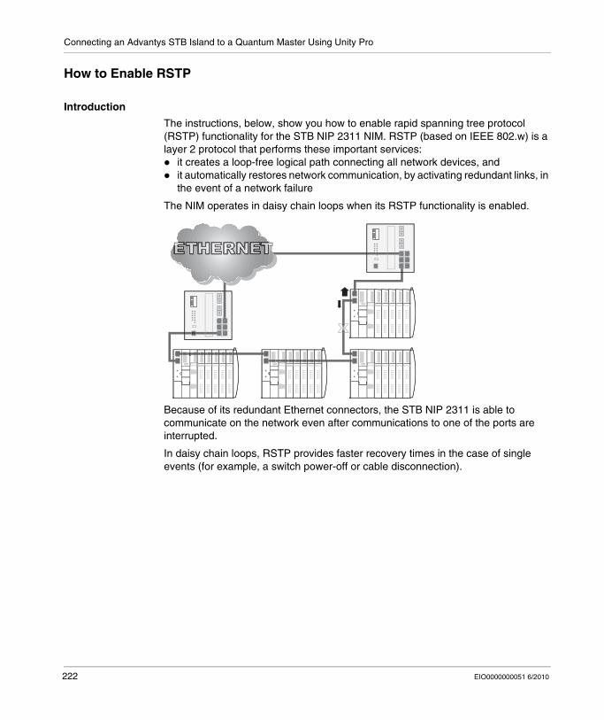
Connecting an Advantys STB Island to a Quantum Master Using Unity Pro
How to Enable RSTP
Introduction
The instructions, below, show you how to enable rapid spanning tree protocol (RSTP) functionality for the STB NIP 2311 NIM. RSTP (based on IEEE 802.w) is a layer 2 protocol that performs these important services:
it creates a loop-free logical path connecting all network devices, andit automatically restores network communication, by activating redundant links, in the event of a network failure
The NIM operates in daisy chain loops when its RSTP functionality is enabled.
Because of its redundant Ethernet connectors, the STB NIP 2311 is able to communicate on the network even after communications to one of the ports are interrupted.
In daisy chain loops, RSTP provides faster recovery times in the case of single events (for example, a switch power-off or cable disconnection).
222 EIO0000000051 6/2010
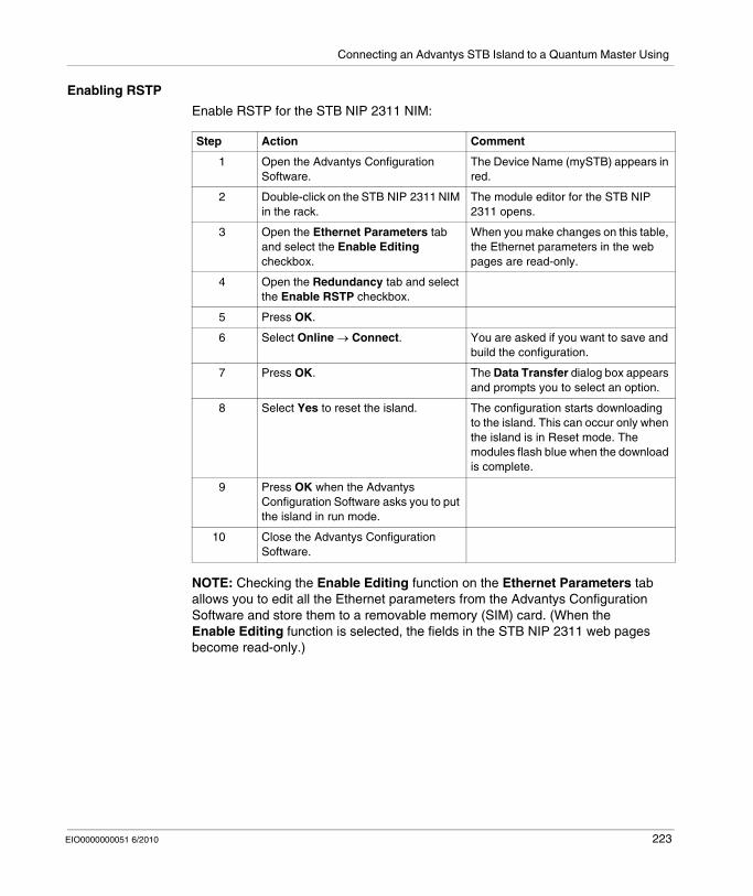
Connecting an Advantys STB Island to a Quantum Master Using
Enabling RSTP
Enable RSTP for the STB NIP 2311 NIM:
NOTE: Checking the Enable Editing function on the Ethernet Parameters tab allows you to edit all the Ethernet parameters from the Advantys Configuration Software and store them to a removable memory (SIM) card. (When the Enable Editing function is selected, the fields in the STB NIP 2311 web pages become read-only.)
Step Action Comment
1 Open the Advantys Configuration Software.
The Device Name (mySTB) appears in red.
2 Double-click on the STB NIP 2311 NIM in the rack.
The module editor for the STB NIP 2311 opens.
3 Open the Ethernet Parameters tab and select the Enable Editing checkbox.
When you make changes on this table, the Ethernet parameters in the web pages are read-only.
4 Open the Redundancy tab and select the Enable RSTP checkbox.
5 Press OK.
6 Select Online → Connect. You are asked if you want to save and build the configuration.
7 Press OK. The Data Transfer dialog box appears and prompts you to select an option.
8 Select Yes to reset the island. The configuration starts downloading to the island. This can occur only when the island is in Reset mode. The modules flash blue when the download is complete.
9 Press OK when the Advantys Configuration Software asks you to put the island in run mode.
10 Close the Advantys Configuration Software.
EIO0000000051 6/2010 223
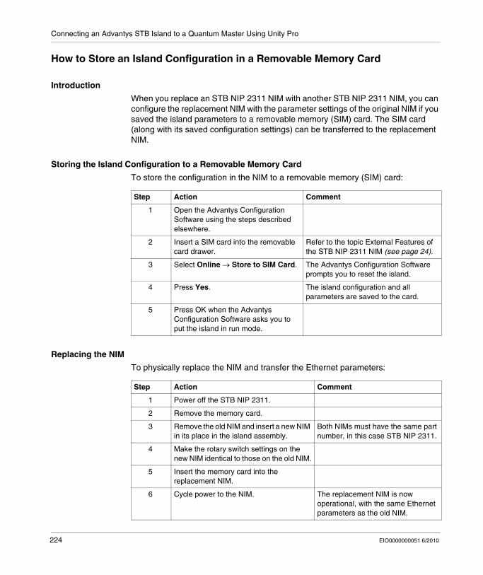
Connecting an Advantys STB Island to a Quantum Master Using Unity Pro
How to Store an Island Configuration in a Removable Memory Card
Introduction
When you replace an STB NIP 2311 NIM with another STB NIP 2311 NIM, you can configure the replacement NIM with the parameter settings of the original NIM if you saved the island parameters to a removable memory (SIM) card. The SIM card (along with its saved configuration settings) can be transferred to the replacement NIM.
Storing the Island Configuration to a Removable Memory Card
To store the configuration in the NIM to a removable memory (SIM) card:
Replacing the NIM
To physically replace the NIM and transfer the Ethernet parameters:
Step Action Comment
1 Open the Advantys Configuration Software using the steps described elsewhere.
2 Insert a SIM card into the removable card drawer.
Refer to the topic External Features of the STB NIP 2311 NIM (see page 24).
3 Select Online → Store to SIM Card. The Advantys Configuration Software prompts you to reset the island.
4 Press Yes. The island configuration and all parameters are saved to the card.
5 Press OK when the Advantys Configuration Software asks you to put the island in run mode.
Step Action Comment
1 Power off the STB NIP 2311.
2 Remove the memory card.
3 Remove the old NIM and insert a new NIM in its place in the island assembly.
Both NIMs must have the same part number, in this case STB NIP 2311.
4 Make the rotary switch settings on the new NIM identical to those on the old NIM.
5 Insert the memory card into the replacement NIM.
6 Cycle power to the NIM. The replacement NIM is now operational, with the same Ethernet parameters as the old NIM.
224 EIO0000000051 6/2010
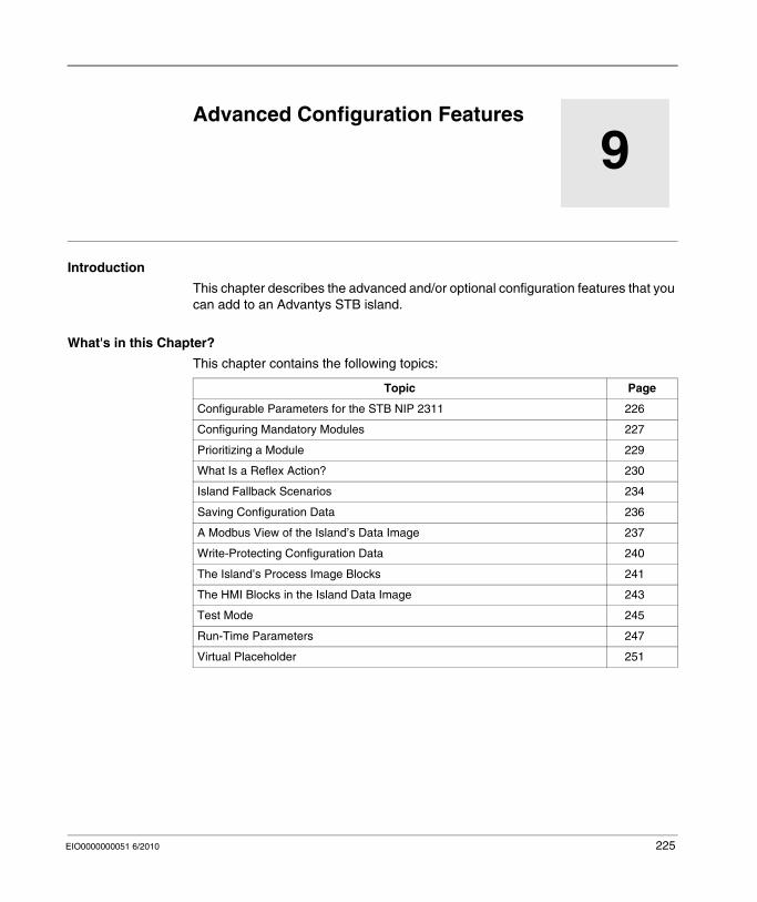
EIO0000000051 6/2010
9
Advanced Configuration Features
EIO0000000051 6/2010
Advanced Configuration Features
Introduction
This chapter describes the advanced and/or optional configuration features that you can add to an Advantys STB island.
What's in this Chapter?
This chapter contains the following topics:
Topic Page
Configurable Parameters for the STB NIP 2311 226
Configuring Mandatory Modules 227
Prioritizing a Module 229
What Is a Reflex Action? 230
Island Fallback Scenarios 234
Saving Configuration Data 236
A Modbus View of the Island’s Data Image 237
Write-Protecting Configuration Data 240
The Island’s Process Image Blocks 241
The HMI Blocks in the Island Data Image 243
Test Mode 245
Run-Time Parameters 247
Virtual Placeholder 251
225
Advanced Configuration Features
Configurable Parameters for the STB NIP 2311
Introduction
The STB NIP 2311 network interface module can be configured using either:Advantys configuration software (see page 59), orthe STB NIP 2311 module’s embedded web pages (see page 143)
Refer to the sections of this document describing each of the above features for information on how to configure the STB NIP 2311 module using these tools.
226 EIO0000000051 6/2010
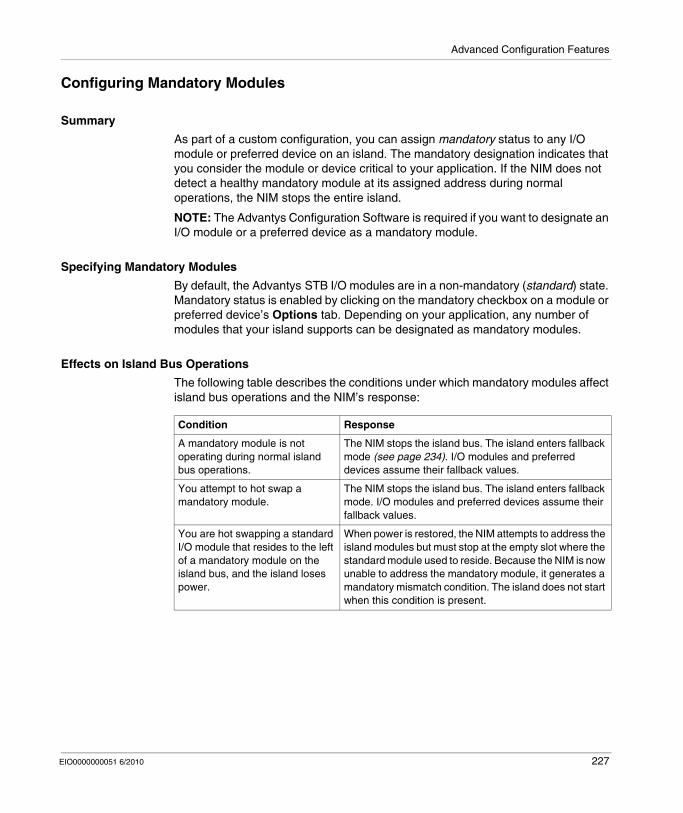
Advanced Configuration Features
Configuring Mandatory Modules
Summary
As part of a custom configuration, you can assign mandatory status to any I/O module or preferred device on an island. The mandatory designation indicates that you consider the module or device critical to your application. If the NIM does not detect a healthy mandatory module at its assigned address during normal operations, the NIM stops the entire island.
NOTE: The Advantys Configuration Software is required if you want to designate an I/O module or a preferred device as a mandatory module.
Specifying Mandatory Modules
By default, the Advantys STB I/O modules are in a non-mandatory (standard) state. Mandatory status is enabled by clicking on the mandatory checkbox on a module or preferred device’s Options tab. Depending on your application, any number of modules that your island supports can be designated as mandatory modules.
Effects on Island Bus Operations
The following table describes the conditions under which mandatory modules affect island bus operations and the NIM’s response:
Condition Response
A mandatory module is not operating during normal island bus operations.
The NIM stops the island bus. The island enters fallback mode (see page 234). I/O modules and preferred devices assume their fallback values.
You attempt to hot swap a mandatory module.
The NIM stops the island bus. The island enters fallback mode. I/O modules and preferred devices assume their fallback values.
You are hot swapping a standard I/O module that resides to the left of a mandatory module on the island bus, and the island loses power.
When power is restored, the NIM attempts to address the island modules but must stop at the empty slot where the standard module used to reside. Because the NIM is now unable to address the mandatory module, it generates a mandatory mismatch condition. The island does not start when this condition is present.
EIO0000000051 6/2010 227
Advanced Configuration Features
Recovering from a Mandatory Stop
Pushing the RST button (see page 49) while recovering from a mandatory stop loads the island’s default configuration data.
Hot Swapping a Mandatory Module
If the NIM has stopped island bus operations because it cannot detect a healthy mandatory module, you can recover island bus operations by installing a healthy module of the same type. The NIM automatically configures the replacement module to match the removed module. Assuming that other modules and devices on the island bus are correctly configured and conform to their configuration data as written to Flash memory, the NIM starts of restarts normal island bus operations.
WARNINGUNINTENDED EQUIPMENT OPERATION/LOSS OF CONFIGURATION—RST BUTTON WHILE RECOVERING FROM MANDATORY STOP
Pushing the RST button (see page 49) causes the island bus to reconfigure itself with factory-default operating parameters, which do not support mandatory I/O status.
Do not attempt to restart the island by pushing the RST button.If a module is unhealthy, replace it with the same module type.
Failure to follow these instructions can result in death, serious injury, or equipment damage.
228 EIO0000000051 6/2010
Advanced Configuration Features
Prioritizing a Module
Summary
Using the Advantys configuration software, you can assign priority to digital input modules in your island assembly. Prioritization is a method of fine tuning the NIM’s I/O scan of the island bus. The NIM will scan modules with priority more frequently than other island modules.
Limitations
You can prioritize only modules with digital inputs. You cannot prioritize output modules or analog modules. You can prioritize only 10 modules for a given island.
EIO0000000051 6/2010 229
Advanced Configuration Features
What Is a Reflex Action?
Summary
Reflex actions are small routines that perform dedicated logical functions directly on the Advantys island bus. They allow output modules on the island to act on data and drive field actuators directly, without requiring the intervention of the fieldbus master.
A typical reflex action comprises one or two function blocks that perform:
Boolean AND or exclusive-OR operationscomparisons of an analog input value to user-specified threshold valuesup- or down-counter operationstimer operationsthe triggering of a latch to hold a digital value high or lowthe triggering of a latch to hold an analog value at a specific value
The island bus optimizes reflex response time by assigning the highest transmission priority to its reflex actions. Reflex actions take some of the processing workload off the fieldbus master, and they offer a faster, more efficient use of system bandwidth.
How Reflex Actions Behave
Reflex actions are designed to control outputs independently of the fieldbus master controller. They may continue to turn outputs on and off even when power is removed from the fieldbus master. Use prudent design practices when you use reflex actions in your application.
WARNINGUNEXPECTED OUTPUT OPERATION
For outputs that are configured to respond to reflex actions, the output state represented in the island’s network interface module (NIM) may not represent the actual states of the outputs.
Turn off field power before you service any equipment connected to the island.For digital outputs, view the echo register for the module in the process image to see the actual output state.For analog outputs, there is no echo register in the process image. To view an actual analog output value, connect the analog output channel to an analog input channel.
Failure to follow these instructions can result in death, serious injury, or equipment damage.
230 EIO0000000051 6/2010
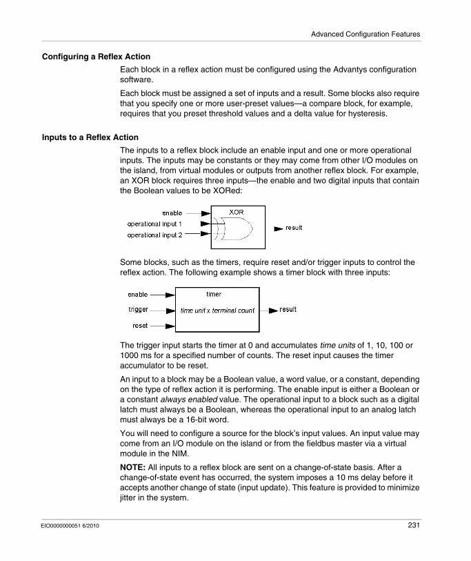
Advanced Configuration Features
Configuring a Reflex Action
Each block in a reflex action must be configured using the Advantys configuration software.
Each block must be assigned a set of inputs and a result. Some blocks also require that you specify one or more user-preset values—a compare block, for example, requires that you preset threshold values and a delta value for hysteresis.
Inputs to a Reflex Action
The inputs to a reflex block include an enable input and one or more operational inputs. The inputs may be constants or they may come from other I/O modules on the island, from virtual modules or outputs from another reflex block. For example, an XOR block requires three inputs—the enable and two digital inputs that contain the Boolean values to be XORed:
Some blocks, such as the timers, require reset and/or trigger inputs to control the reflex action. The following example shows a timer block with three inputs:
The trigger input starts the timer at 0 and accumulates time units of 1, 10, 100 or 1000 ms for a specified number of counts. The reset input causes the timer accumulator to be reset.
An input to a block may be a Boolean value, a word value, or a constant, depending on the type of reflex action it is performing. The enable input is either a Boolean or a constant always enabled value. The operational input to a block such as a digital latch must always be a Boolean, whereas the operational input to an analog latch must always be a 16-bit word.
You will need to configure a source for the block’s input values. An input value may come from an I/O module on the island or from the fieldbus master via a virtual module in the NIM.
NOTE: All inputs to a reflex block are sent on a change-of-state basis. After a change-of-state event has occurred, the system imposes a 10 ms delay before it accepts another change of state (input update). This feature is provided to minimize jitter in the system.
EIO0000000051 6/2010 231
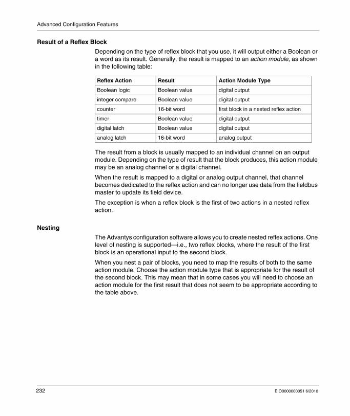
Advanced Configuration Features
Result of a Reflex Block
Depending on the type of reflex block that you use, it will output either a Boolean or a word as its result. Generally, the result is mapped to an action module, as shown in the following table:
The result from a block is usually mapped to an individual channel on an output module. Depending on the type of result that the block produces, this action module may be an analog channel or a digital channel.
When the result is mapped to a digital or analog output channel, that channel becomes dedicated to the reflex action and can no longer use data from the fieldbus master to update its field device.
The exception is when a reflex block is the first of two actions in a nested reflex action.
Nesting
The Advantys configuration software allows you to create nested reflex actions. One level of nesting is supported—i.e., two reflex blocks, where the result of the first block is an operational input to the second block.
When you nest a pair of blocks, you need to map the results of both to the same action module. Choose the action module type that is appropriate for the result of the second block. This may mean that in some cases you will need to choose an action module for the first result that does not seem to be appropriate according to the table above.
Reflex Action Result Action Module Type
Boolean logic Boolean value digital output
integer compare Boolean value digital output
counter 16-bit word first block in a nested reflex action
timer Boolean value digital output
digital latch Boolean value digital output
analog latch 16-bit word analog output
232 EIO0000000051 6/2010
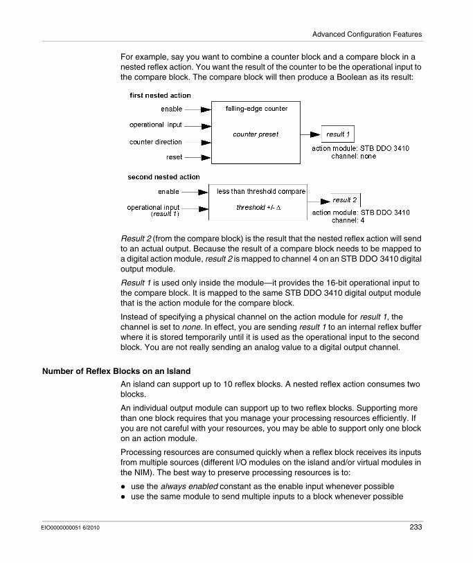
Advanced Configuration Features
For example, say you want to combine a counter block and a compare block in a nested reflex action. You want the result of the counter to be the operational input to the compare block. The compare block will then produce a Boolean as its result:
Result 2 (from the compare block) is the result that the nested reflex action will send to an actual output. Because the result of a compare block needs to be mapped to a digital action module, result 2 is mapped to channel 4 on an STB DDO 3410 digital output module.
Result 1 is used only inside the module—it provides the 16-bit operational input to the compare block. It is mapped to the same STB DDO 3410 digital output module that is the action module for the compare block.
Instead of specifying a physical channel on the action module for result 1, the channel is set to none. In effect, you are sending result 1 to an internal reflex buffer where it is stored temporarily until it is used as the operational input to the second block. You are not really sending an analog value to a digital output channel.
Number of Reflex Blocks on an Island
An island can support up to 10 reflex blocks. A nested reflex action consumes two blocks.
An individual output module can support up to two reflex blocks. Supporting more than one block requires that you manage your processing resources efficiently. If you are not careful with your resources, you may be able to support only one block on an action module.
Processing resources are consumed quickly when a reflex block receives its inputs from multiple sources (different I/O modules on the island and/or virtual modules in the NIM). The best way to preserve processing resources is to:
use the always enabled constant as the enable input whenever possibleuse the same module to send multiple inputs to a block whenever possible
EIO0000000051 6/2010 233
Advanced Configuration Features
Island Fallback Scenarios
Introduction
In the event of a communications interruption on the island or between the island and the fieldbus, output data is put into a fallback state. In this state, output data is replaced with pre-configured fallback values. This makes known the module’s output data values when the system recovers from this condition.
Fallback Scenarios
There are several scenarios in which Advantys STB output modules go into their fallback states:
loss of fieldbus communications: Communications with the PLC are lost.
loss of island bus communications: There is an internal island bus communications interruption, indicated by a missing heartbeat message from either the NIM or a module.change of operating state: The NIM may command the island I/O modules to switch from a running to a non-running (stopped or reset) state.missing or non-operating mandatory module: The NIM detects this condition for a mandatory island module.
NOTE: If a mandatory (or any other) module is not operating, it needs to be replaced. The module itself does not go into its fallback state.
In all of these fallback scenarios, the NIM disables the heartbeat message.
Heartbeat Message
The Advantys STB system relies on a heartbeat message to verify the integrity and continuity of communications between the NIM and the island modules. The health of island modules and the overall integrity of the Advantys STB system are monitored through the transmission and reception of these periodic island bus messages.
Because island I/O modules are configured to monitor the NIM’s heartbeat message, output modules go into their fallback states if they do not receive a heartbeat message from the NIM within the defined interval.
Fallback States for Reflex Functions
Only an output module channel to which the result of a reflex action (see page 230) has been mapped can operate in the absence of the NIM’s heartbeat message.
When modules that provide input for reflex functionality are not operating or are removed from the island, the channels that hold the result of those reflex actions go into their fallback states.
234 EIO0000000051 6/2010
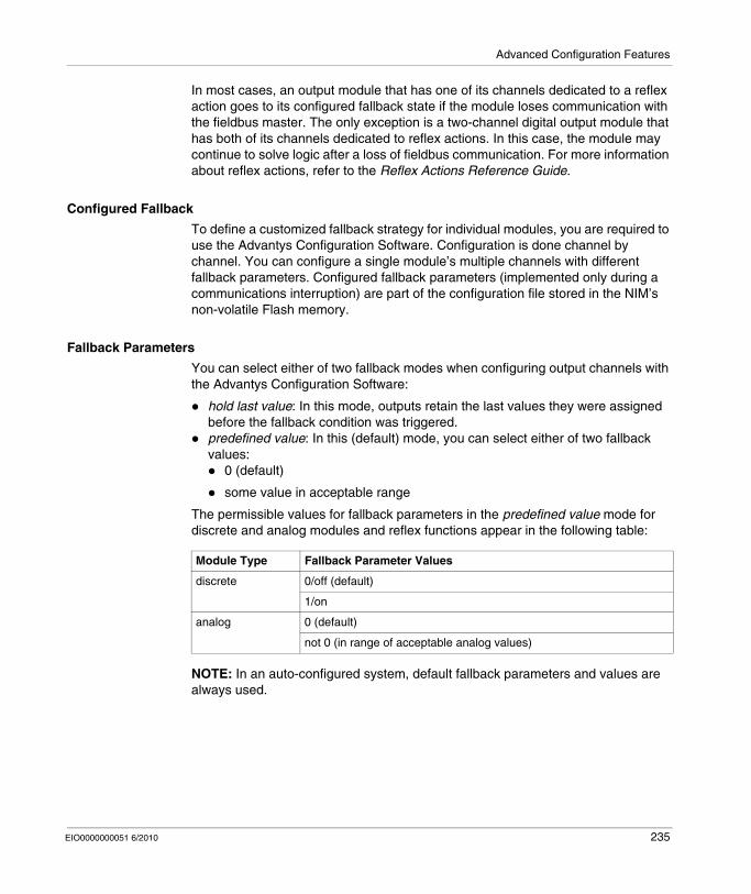
Advanced Configuration Features
In most cases, an output module that has one of its channels dedicated to a reflex action goes to its configured fallback state if the module loses communication with the fieldbus master. The only exception is a two-channel digital output module that has both of its channels dedicated to reflex actions. In this case, the module may continue to solve logic after a loss of fieldbus communication. For more information about reflex actions, refer to the Reflex Actions Reference Guide.
Configured Fallback
To define a customized fallback strategy for individual modules, you are required to use the Advantys Configuration Software. Configuration is done channel by channel. You can configure a single module’s multiple channels with different fallback parameters. Configured fallback parameters (implemented only during a communications interruption) are part of the configuration file stored in the NIM’s non-volatile Flash memory.
Fallback Parameters
You can select either of two fallback modes when configuring output channels with the Advantys Configuration Software:
hold last value: In this mode, outputs retain the last values they were assigned before the fallback condition was triggered.predefined value: In this (default) mode, you can select either of two fallback values:
0 (default)
some value in acceptable range
The permissible values for fallback parameters in the predefined value mode for discrete and analog modules and reflex functions appear in the following table:
NOTE: In an auto-configured system, default fallback parameters and values are always used.
Module Type Fallback Parameter Values
discrete 0/off (default)
1/on
analog 0 (default)
not 0 (in range of acceptable analog values)
EIO0000000051 6/2010 235
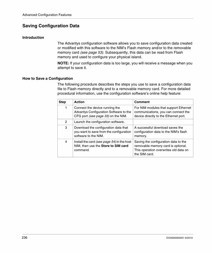
Advanced Configuration Features
Saving Configuration Data
Introduction
The Advantys configuration software allows you to save configuration data created or modified with this software to the NIM’s Flash memory and/or to the removable memory card (see page 53). Subsequently, this data can be read from Flash memory and used to configure your physical island.
NOTE: If your configuration data is too large, you will receive a message when you attempt to save it.
How to Save a Configuration
The following procedure describes the steps you use to save a configuration data file to Flash memory directly and to a removable memory card. For more detailed procedural information, use the configuration software’s online help feature:
Step Action Comment
1 Connect the device running the Advantys Configuration Software to the CFG port (see page 33) on the NIM.
For NIM modules that support Ethernet communications, you can connect the device directly to the Ethernet port.
2 Launch the configuration software.
3 Download the configuration data that you want to save from the configuration software to the NIM.
A successful download saves the configuration data to the NIM's flash memory.
4 Install the card (see page 54) in the host NIM, then use the Store to SIM card command.
Saving the configuration data to the removable memory card is optional. This operation overwrites old data on the SIM card.
236 EIO0000000051 6/2010
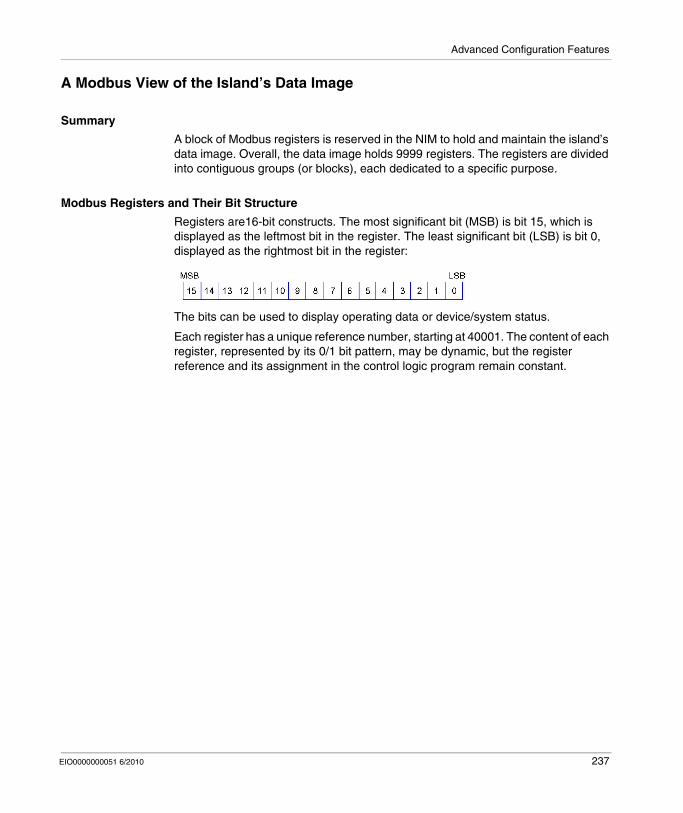
Advanced Configuration Features
A Modbus View of the Island’s Data Image
Summary
A block of Modbus registers is reserved in the NIM to hold and maintain the island’s data image. Overall, the data image holds 9999 registers. The registers are divided into contiguous groups (or blocks), each dedicated to a specific purpose.
Modbus Registers and Their Bit Structure
Registers are16-bit constructs. The most significant bit (MSB) is bit 15, which is displayed as the leftmost bit in the register. The least significant bit (LSB) is bit 0, displayed as the rightmost bit in the register:
The bits can be used to display operating data or device/system status.
Each register has a unique reference number, starting at 40001. The content of each register, represented by its 0/1 bit pattern, may be dynamic, but the register reference and its assignment in the control logic program remain constant.
EIO0000000051 6/2010 237
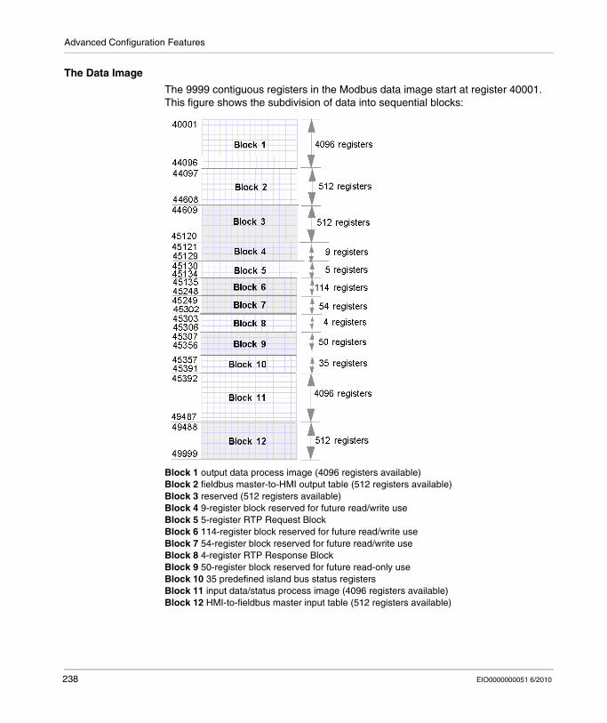
Advanced Configuration Features
The Data Image
The 9999 contiguous registers in the Modbus data image start at register 40001. This figure shows the subdivision of data into sequential blocks:
Block 1 output data process image (4096 registers available)Block 2 fieldbus master-to-HMI output table (512 registers available)Block 3 reserved (512 registers available)Block 4 9-register block reserved for future read/write useBlock 5 5-register RTP Request BlockBlock 6 114-register block reserved for future read/write useBlock 7 54-register block reserved for future read/write useBlock 8 4-register RTP Response BlockBlock 9 50-register block reserved for future read-only useBlock 10 35 predefined island bus status registersBlock 11 input data/status process image (4096 registers available)Block 12 HMI-to-fieldbus master input table (512 registers available)
238 EIO0000000051 6/2010
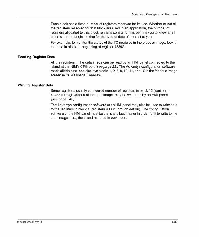
Advanced Configuration Features
Each block has a fixed number of registers reserved for its use. Whether or not all the registers reserved for that block are used in an application, the number of registers allocated to that block remains constant. This permits you to know at all times where to begin looking for the type of data of interest to you.
For example, to monitor the status of the I/O modules in the process image, look at the data in block 11 beginning at register 45392.
Reading Register Data
All the registers in the data image can be read by an HMI panel connected to the island at the NIM’s CFG port (see page 33). The Advantys configuration software reads all this data, and displays blocks 1, 2, 5, 8, 10, 11, and 12 in the Modbus Image screen in its I/O Image Overview.
Writing Register Data
Some registers, usually configured number of registers in block 12 (registers 49488 through 49999) of the data image, may be written to by an HMI panel (see page 243).
The Advantys configuration software or an HMI panel may also be used to write data to the registers in block 1 (registers 40001 through 44096). The configuration software or the HMI panel must be the island bus master in order for it to write to the data image—i.e., the island must be in test mode.
EIO0000000051 6/2010 239
Advanced Configuration Features
Write-Protecting Configuration Data
Introduction
As part of a custom configuration, you can password-protect an Advantys STB island. Only authorized persons have write privileges to the configuration data currently stored in Flash memory:
Use the Advantys Configuration Software to password-protect an island’s configuration.For some modules, it is possible to password-protect the island configuration through an embedded web site.
The island runs normally in protected mode. All users have the ability to monitor (read) the activity on the island bus. If a configuration is write-protected, access to it is restricted in the following ways:
An unauthorized user is unable to overwrite the current configuration data in Flash memory.The RST button (see page 49) is disabled, and pushing it has no effect on island bus operations.The presence of a removable memory card (see page 53) is ignored. The configuration data currently stored in Flash cannot be overwritten by data on the card.
NOTE: The STB NIP 2311 NIM never ignores the removable memory card.
Password Characteristics
A password must meet the following criteria:It must be between 0 and 6 characters in length.Only alphanumeric ASCII characters are permitted.The password is case-sensitive.
If password protection is enabled, your password is saved to Flash memory (or to a removable memory card) when you save the configuration data.
NOTE: A password-protected configuration is inaccessible to anyone who does not know the password. Your system administrator is responsible for keeping track of the password and the list of authorized users. If the assigned password is lost or forgotten, you are unable to change the island’s configuration.
If the password is lost and you need to reconfigure the island, you need to perform a destructive reflash of the NIM. This procedure is described on the Advantys STB product Web site at www.schneiderautomation.com.
240 EIO0000000051 6/2010
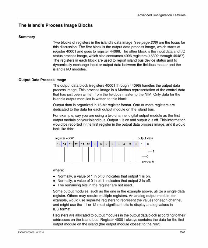
Advanced Configuration Features
The Island’s Process Image Blocks
Summary
Two blocks of registers in the island’s data image (see page 238) are the focus for this discussion. The first block is the output data process image, which starts at register 40001 and goes to register 44096. The other block is the input data and I/O status process image, which also consumes 4096 registers (45392 through 49487). The registers in each block are used to report island bus device status and to dynamically exchange input or output data between the fieldbus master and the island’s I/O modules.
Output Data Process Image
The output data block (registers 40001 through 44096) handles the output data process image. This process image is a Modbus representation of the control data that has just been written from the fieldbus master to the NIM. Only data for the island’s output modules is written to this block.
Output data is organized in 16-bit register format. One or more registers are dedicated to the data for each output module on the island bus.
For example, say you are using a two-channel digital output module as the first output module on your island bus. Output 1 is on and output 2 is off. This information would be reported in the first register in the output data process image, and it would look like this:
where:
Normally, a value of 1 in bit 0 indicates that output 1 is on.Normally, a value of 0 in bit 1 indicates that output 2 is off.The remaining bits in the register are not used.
Some output modules, such as the one in the example above, utilize a single data register. Others may require multiple registers. An analog output module, for example, would use separate registers to represent the values for each channel, and might use the 11 or 12 most significant bits to display analog values in IEC format.
Registers are allocated to output modules in the output data block according to their addresses on the island bus. Register 40001 always contains the data for the first output module on the island (the output module closest to the NIM).
EIO0000000051 6/2010 241
Advanced Configuration Features
Output Data Read/Write Capabilities
The registers in the output data process image are read/write-capable.
You can read (i.e., monitor) the process image using an HMI panel or the Advantys Configuration Software. The data content that you see when you monitor the output data image registers is updated in near-real time.
The island’s fieldbus master also writes updated control data to the output data process image.
Input Data and I/O Status Process Image
The input data and I/O status block (registers 45392 through 49487) handles the input data and I/O status process image. Every I/O module on the island bus has information that needs to be stored in this block.
Each digital input module reports data (the on/off status of its input channels) in one register of input data and I/O status block, then reports its status in the next register.Each analog input module uses four registers in the input data and I/O status block. It represents the analog data for each channel in separate registers and the status of each channel in separate registers. Analog data is usually represented with 11- or 12-bit resolution in the IEC format; status in an analog input channel is usually represented by a series of status bits that report the presence or absence of an out-of-range value in a channel.Each digital output module reports an echo of its output data to a register in the input data and I/O status block. Echo output data registers are essentially copies of the register values that appear in the output data process image. This data is usually not of much interest, but it can be useful in the event that a digital output channel has been configured for a reflex action. In this case, the fieldbus master can see the bit value in the echo output data register even though the output channel is being updated inside the island bus.Each analog output module uses two registers in the input data and I/O status block to report status. Status in an analog output channel is usually represented by a series of status bits that report the presence or absence of an out-of-range value in a channel. Analog output modules do not report data in this block.
A detailed view of how the registers in the input data and I/O status block are implemented is shown in the process image example.
242 EIO0000000051 6/2010
Advanced Configuration Features
The HMI Blocks in the Island Data Image
Summary
An HMI panel that communicates using the Modbus protocol can be connected to the CFG port (see page 33) on the NIM. Using the Advantys configuration software, you can reserve one or two blocks of registers in the data image (see page 237) to support HMI data exchange. When an HMI panel writes to one of these blocks, that data is accessible to the fieldbus master (as inputs). Data written by the fieldbus master (as outputs) is stored in a different reserved block of registers that the HMI panel can read.
HMI Panel Configuration
Advantys STB supports the ability of an HMI panel to act as:an input device, which writes data to the island’s data image that is read by the fieldbus masteran output device, which can read data written by the fieldbus master to the island’s data imagea combined I/O device
HMI Input Data Exchange
Input data to the fieldbus master can be generated by the HMI panel. Input controls on an HMI panel might be elements such as:
push buttonsswitchesa data entry keypad
To use an HMI panel as an input device on the island, you need to enable the HMI-to-fieldbus master block in the island’s data image (see page 238) and specify the number of registers in this block that you want to use for HMI-to-fieldbus master data transfers. You must use the Advantys configuration software to make these configuration adjustments.
The HMI-to-fieldbus master block can comprise up to 512 registers, ranging from register 49488 to 49999. (Your actual register limit will be dictated by your fieldbus.) This block follows immediately after the standard input data and I/O status process image (see page 242) block (registers 45392 through 49487) in the island’s data image.
The HMI panel writes the input data to a specified number of registers in the HMI-to-fieldbus master block. The NIM manages the transfer of the HMI data in these registers as part of the overall input data transfer—it converts the 16-bit register data to a fieldbus-specific data format and transfers it together with the standard input data and I/O status process image to the fieldbus. The fieldbus master sees and responds to HMI data as if it were standard input data.
EIO0000000051 6/2010 243
Advanced Configuration Features
HMI Output Data Exchange
In turn, output data written by the fieldbus master can be used to update enunciator elements on the HMI panel. Enunciator elements might be:
display indicatorsbuttons or screen images that change color or shapedata display screens (for example, temperature read-outs)
To use the HMI panel as an output device, you need to enable the fieldbus-to-HMI block in the island’s data image (see page 238) and specify the number of registers in this block that you want to use. You need to use the Advantys configuration software to make these adjustments to your configuration.
The fieldbus master-to-HMI block can comprise up to 512 registers, ranging from register 44097 to 44608. This block follows immediately after the standard output data process image (see page 241) block (registers 40001 through 44096) in the island’s data image.
The fieldbus master writes output update data in native fieldbus format to the HMI data block concurrent with writing this data to the output data process image area. The output data is placed in the fieldbus master-to-HMI block. Upon request by the HMI via a Modbus read command, the role of the NIM is to receive this output data, convert it to16-bit Modbus format, and send it over the Modbus connection at the CFG port to the HMI panel.
NOTE: The read command enables all Modbus registers to be read, not just those in the block reserved for fieldbus master-to-HMI data exchange.
244 EIO0000000051 6/2010
Advanced Configuration Features
Test Mode
Summary
Test Mode indicates that the output data of the STB island’s process image is not controlled by a fieldbus master device, but is instead controlled by either the Advantys Configuration Software or an HMI. When the STB island is operating in Test Mode, the fieldbus master cannot write the STB island’s outputs, but can continue to read its inputs and diagnostic data.
Test Mode is configured off-line, downloaded with the island configuration, then activated online.
Select Test Mode Settings in the Online menu to open the Test Mode configuration window, where you can select a test mode setting. Test Mode settings are stored with other STB island configuration settings both in the NIM’s flash memory and in a SIM card, if one is attached to the NIM.
When Test Mode is activated, the NIM’s TEST LED is lit, and bit #5 of the NIM Status word in register 45391 is set to 1.
NOTE: Loss of Modbus communications do not affect Test Mode.
There are three Test Mode settings:
Temporary Test ModePersistent Test ModePassword Test Mode
The following sections describe the process and effect of activating Test Mode.
Temporary Test Mode
When operating online, use the Advantys Configuration Software (not an HMI) to activate Temporary Test Mode, by selecting Test Mode in the Online menu.
Once activated, Temporary Test Mode is deactivated by:
de-selecting Test Mode in the Online menucycling power to the NIMselecting Reset in the Online menuperforming Autoconfigurationdownloading a new island configuration to the NIM (or inserting a SIM card with a new island configuration into the NIM and cycling power to the NIM).
Temporary Test Mode is the default Test Mode configuration setting.
EIO0000000051 6/2010 245
Advanced Configuration Features
Persistent Test Mode
Use the Advantys Configuration Software to configure the STB island for Persistent Test Mode. When the download of this configuration is complete, Persistent Test Mode is activated. Thereafter, the STB island operates in Test Mode each time power is cycled to the island. When Persistent Test Mode is activated, the STB island’s process image output data is controlled exclusively by either the HMI or the configuration software. The fieldbus master no longer controls these outputs.
Persistent Test Mode is deactivated by:
downloading a new island configuration to the NIM (or inserting a SIM card with a new island configuration into the NIM and cycling power to the NIM)performing Autoconfiguration.
Password Test Mode
Use the Advantys Configuration Software to enter a password to the STB island’s configuration settings. The password you input must have an integer value from 1 to 65535 (FFFF hex).
After the changed configuration ( including the password) has been downloaded, you can activate Password Test Mode only by using an HMI to issue a single Modbus Register write command to send the password value to Modbus Register 45120.
After Password Test Mode is activated, the STB island’s process image output data is controlled by either the HMI or the configuration software. In this case, the fieldbus master no longer controls these outputs.
Password Test Mode, once activated, is deactivated by:
cycling power to the NIMselecting Reset in the Online menuperforming Autoconfigurationdownloading a new island configuration to the NIM (or inserting a SIM card with a new island configuration into the NIM and cycling power to the NIM)using an HMI to issue a single Modbus register write command to send the password value to Modbus Register 45121 (STB NIC 2212 and STB NIP 2311 NIMs only)
NOTE: Password Test Mode must be activated only by using the NIM’s configuration port. All attempts to enter Password Test Mode using the fieldbus (via NIM models STB NMP 2212 or STB NIP 2212) are unsuccessful.
246 EIO0000000051 6/2010
Advanced Configuration Features
Run-Time Parameters
Introduction
For STB modules, the Advantys Configuration Software provides the RTP (run-time parameters) feature. It can be used for monitoring and modifying selected I/O parameters and Island bus status registers of the NIM while the Island is running. This feature is available only in standard STB NIMs with firmware version 2.0 or later.
RTP must be configured using the Advantys Configuration Software before it can be used. RTP is not configured by default. Configure RTP by selecting Configure run-time Parameters in the Options tab of the NIM Module Editor. This allocates the necessary registers within the NIM’s data process image to support this feature.
Request and Response Blocks
Once configured, use the RTP feature by writing up to 5 reserved words in the NIM’s output data process image (the RTP request block) and by reading the value of 4 reserved words in the NIM’s input data process image (the RTP response block). The Advantys Configuration Software displays both blocks of reserved RTP words in the Island’s I/O Image Overview dialog box, both in the Modbus Image tab and (for NIMs with a separate fieldbus image) in the Fieldbus Image tab. In each tab, the blocks of reserved RTP words appear after the block of process I/O data and before the block of HMI data (if any).
NOTE: The Modbus address values of the RTP request and response blocks are the same in all standard NIMs. The fieldbus address values of the RTP request and response blocks depend upon the network type. Use the Fieldbus Image tab of the I/O Image Overview dialog box to obtain the location of the RTP registers. For Modbus Plus and Ethernet networks, use the Modbus register numbers.
Exceptions
Any parameter you modify using the RTP feature does not retain its modified value if one of the following events occurs:
Power is cycled to the NIM. A Reset command is issued to the NIM using the Advantys Configuration Software.A Store to SIM Card command is issued using the Advantys Configuration Software.The module whose parameter has been modified is hot-swapped.If a module is hot-swapped, as indicated by the HOT_SWAP indicator bit, you can use the RTP feature to detect which module has been hot-swapped and to restore the parameters to their previous values.
EIO0000000051 6/2010 247
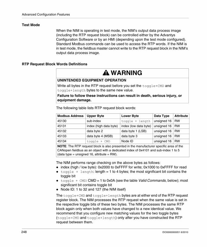
Advanced Configuration Features
Test Mode
When the NIM is operating in test mode, the NIM’s output data process image (including the RTP request block) can be controlled either by the Advantys Configuration Software or by an HMI (depending upon the test mode configured). Standard Modbus commands can be used to access the RTP words. If the NIM is in test mode, the fieldbus master cannot write to the RTP request block in the NIM’s output data process image.
RTP Request Block Words Definitions
The following table lists RTP request block words:
The NIM performs range checking on the above bytes as follows:index (high / low byte): 0x2000 to 0xFFFF for write; 0x1000 to 0xFFFF for readtoggle + length: length = 1 to 4 bytes; the most significant bit contains the toggle bittoggle + CMD: CMD = 1 to 0x0A (see the table Valid Commands, below); most significant bit contains toggle bitNode ID: 1 to 32 and 127 (the NIM itself)
The toggle+CMD and toggle+length bytes are at either end of the RTP request register block. The NIM processes the RTP request when the same value is set in the respective toggle bits of these two bytes. The NIM processes the same RTP block again only when both values have changed to a new identical value. We recommend that you configure new matching values for the two toggle bytes (toggle+CMD and toggle+length) only after you have constructed the RTP request between them.
WARNINGUNINTENDED EQUIPMENT OPERATION
Write all bytes in the RTP request before you set the toggle+CMD and toggle+length bytes to the same new value.
Failure to follow these instructions can result in death, serious injury, or equipment damage.
Modbus Address Upper Byte Lower Byte Data Type Attribute
45130 sub-index toggle + length unsigned 16 RW
45131 index (high data byte) index (low data byte) unsigned 16 RW
45132 data byte 2 data byte 1 (LSB) unsigned 16 RW
45133 data byte 4 (MSB) data byte 3 unsigned 16 RW
45134 toggle + CMD Node ID unsigned 16 RW
NOTE: The RTP request block is also presented in the manufacturer specific area of the CANopen fieldbus as an object with a dedicated index of 0x4101 and sub-index 1 to 5 (data type = unsigned 16, attribute = RW).
248 EIO0000000051 6/2010
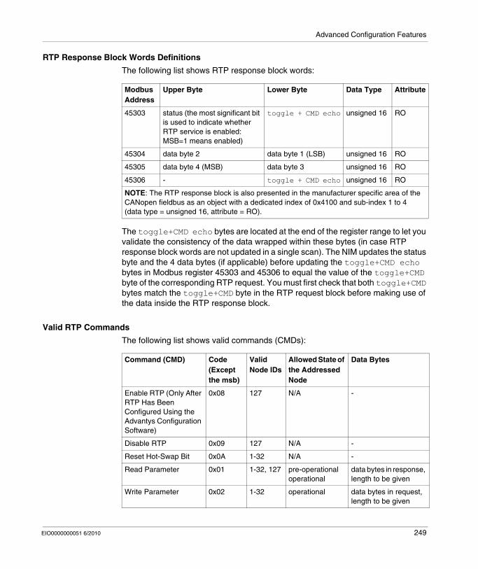
Advanced Configuration Features
RTP Response Block Words Definitions
The following list shows RTP response block words:
The toggle+CMD echo bytes are located at the end of the register range to let you validate the consistency of the data wrapped within these bytes (in case RTP response block words are not updated in a single scan). The NIM updates the status byte and the 4 data bytes (if applicable) before updating the toggle+CMD echo bytes in Modbus register 45303 and 45306 to equal the value of the toggle+CMD byte of the corresponding RTP request. You must first check that both toggle+CMD bytes match the toggle+CMD byte in the RTP request block before making use of the data inside the RTP response block.
Valid RTP Commands
The following list shows valid commands (CMDs):
Modbus Address
Upper Byte Lower Byte Data Type Attribute
45303 status (the most significant bit is used to indicate whether RTP service is enabled: MSB=1 means enabled)
toggle + CMD echo unsigned 16 RO
45304 data byte 2 data byte 1 (LSB) unsigned 16 RO
45305 data byte 4 (MSB) data byte 3 unsigned 16 RO
45306 - toggle + CMD echo unsigned 16 RO
NOTE: The RTP response block is also presented in the manufacturer specific area of the CANopen fieldbus as an object with a dedicated index of 0x4100 and sub-index 1 to 4 (data type = unsigned 16, attribute = RO).
Command (CMD) Code (Except the msb)
Valid Node IDs
Allowed State of the Addressed Node
Data Bytes
Enable RTP (Only After RTP Has Been Configured Using the Advantys Configuration Software)
0x08 127 N/A -
Disable RTP 0x09 127 N/A -
Reset Hot-Swap Bit 0x0A 1-32 N/A -
Read Parameter 0x01 1-32, 127 pre-operational operational
data bytes in response, length to be given
Write Parameter 0x02 1-32 operational data bytes in request, length to be given
EIO0000000051 6/2010 249
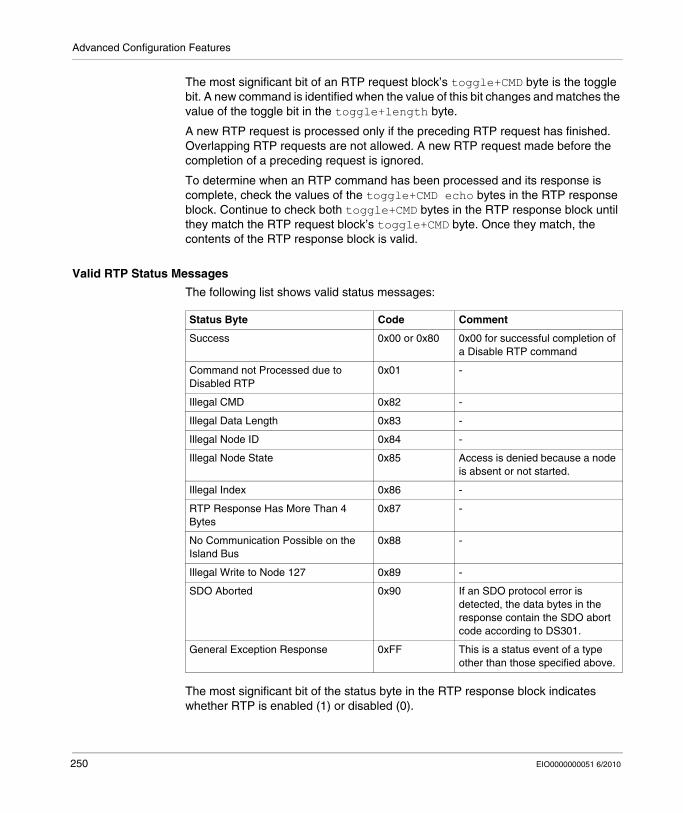
Advanced Configuration Features
The most significant bit of an RTP request block’s toggle+CMD byte is the toggle bit. A new command is identified when the value of this bit changes and matches the value of the toggle bit in the toggle+length byte.
A new RTP request is processed only if the preceding RTP request has finished. Overlapping RTP requests are not allowed. A new RTP request made before the completion of a preceding request is ignored.
To determine when an RTP command has been processed and its response is complete, check the values of the toggle+CMD echo bytes in the RTP response block. Continue to check both toggle+CMD bytes in the RTP response block until they match the RTP request block’s toggle+CMD byte. Once they match, the contents of the RTP response block is valid.
Valid RTP Status Messages
The following list shows valid status messages:
The most significant bit of the status byte in the RTP response block indicates whether RTP is enabled (1) or disabled (0).
Status Byte Code Comment
Success 0x00 or 0x80 0x00 for successful completion of a Disable RTP command
Command not Processed due to Disabled RTP
0x01 -
Illegal CMD 0x82 -
Illegal Data Length 0x83 -
Illegal Node ID 0x84 -
Illegal Node State 0x85 Access is denied because a node is absent or not started.
Illegal Index 0x86 -
RTP Response Has More Than 4 Bytes
0x87 -
No Communication Possible on the Island Bus
0x88 -
Illegal Write to Node 127 0x89 -
SDO Aborted 0x90 If an SDO protocol error is detected, the data bytes in the response contain the SDO abort code according to DS301.
General Exception Response 0xFF This is a status event of a type other than those specified above.
250 EIO0000000051 6/2010
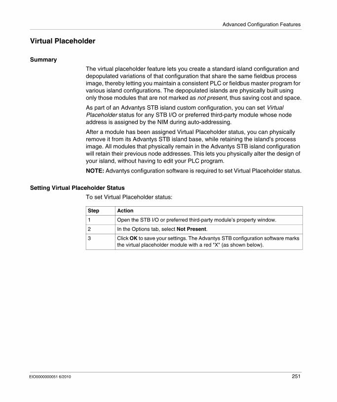
Advanced Configuration Features
Virtual Placeholder
Summary
The virtual placeholder feature lets you create a standard island configuration and depopulated variations of that configuration that share the same fieldbus process image, thereby letting you maintain a consistent PLC or fieldbus master program for various island configurations. The depopulated islands are physically built using only those modules that are not marked as not present, thus saving cost and space.
As part of an Advantys STB island custom configuration, you can set Virtual Placeholder status for any STB I/O or preferred third-party module whose node address is assigned by the NIM during auto-addressing.
After a module has been assigned Virtual Placeholder status, you can physically remove it from its Advantys STB island base, while retaining the island’s process image. All modules that physically remain in the Advantys STB island configuration will retain their previous node addresses. This lets you physically alter the design of your island, without having to edit your PLC program.
NOTE: Advantys configuration software is required to set Virtual Placeholder status.
Setting Virtual Placeholder Status
To set Virtual Placeholder status:
Step Action
1 Open the STB I/O or preferred third-party module’s property window.
2 In the Options tab, select Not Present.
3 Click OK to save your settings. The Advantys STB configuration software marks the virtual placeholder module with a red "X" (as shown below).
EIO0000000051 6/2010 251
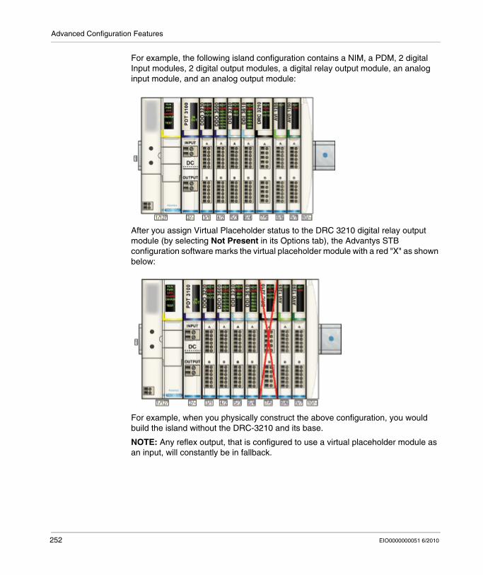
Advanced Configuration Features
For example, the following island configuration contains a NIM, a PDM, 2 digital Input modules, 2 digital output modules, a digital relay output module, an analog input module, and an analog output module:
After you assign Virtual Placeholder status to the DRC 3210 digital relay output module (by selecting Not Present in its Options tab), the Advantys STB configuration software marks the virtual placeholder module with a red "X" as shown below:
For example, when you physically construct the above configuration, you would build the island without the DRC-3210 and its base.
NOTE: Any reflex output, that is configured to use a virtual placeholder module as an input, will constantly be in fallback.
252 EIO0000000051 6/2010
Glossary
EIO0000000051 6/2010
Glossary
0-9
100Base-TAn adaptation of the IEEE 802.3u (Ethernet) standard, the 100Base-T standard uses twisted-pair wiring with a maximum segment length of 100 m (328 ft) and terminates with an RJ-45 connector. A 100Base-T network is a baseband network capable of transmitting data at a maximum speed of 100 Mbit/s. "Fast Ethernet" is another name for 100Base-T, because it is ten times faster than 10Base-T.
10Base-TAn adaptation of the IEEE 802.3 (Ethernet) standard, the 10Base-T standard uses twisted-pair wiring with a maximum segment length of 100 m (328 ft) and terminates with an RJ-45 connector. A 10Base-T network is a baseband network capable of transmitting data at a maximum speed of 10 Mbit/s.
802.3 frameA frame format, specified in the IEEE 802.3 (Ethernet) standard, in which the header specifies the data packet length.
A
agent1. SNMP – the SNMP application that runs on a network device.
2. Fipio – a slave device on a network.
EIO0000000051 6/2010 253
Glossary
analog inputA module that contains circuits that convert analog DC input signals to digital values that can be manipulated by the processor. By implication, these analog inputs are usually direct. That means a data table value directly reflects the analog signal value.
analog outputA module that contains circuits that transmit an analog DC signal proportional to a digital value input to the module from the processor. By implication, these analog outputs are usually direct. That means a data table value directly controls the analog signal value.
application objectIn CAN-based networks, application objects represent device-specific functionality, such as the state of input or output data.
ARPThe ARP (address resolution protocol) is the IP network layer protocol, which uses ARP to map an IP address to a MAC (hardware) address.
auto baudThe automatic assignment and detection of a common baud rate as well as the ability of a device on a network to adapt to that rate.
auto-addressingThe assignment of an address to each Island bus I/O module and preferred device.
auto-configurationThe ability of Island modules to operate with predefined default parameters. A configuration of the Island bus based completely on the actual assembly of I/O modules.
B
basic I/OLow-cost Advantys STB input/output modules that use a fixed set of operating parameters. A basic I/O module cannot be reconfigured with the Advantys Configuration Software and cannot be used in reflex actions.
254 EIO0000000051 6/2010
Glossary
basic network interfaceA low-cost Advantys STB network interface module that supports up to 12 Advantys STB I/O modules. A basic NIM does not support the Advantys Configuration Software, reflex actions, nor the use of an HMI panel.
basic power distribution moduleA low-cost Advantys STB PDM that distributes sensor power and actuator power over a single field power bus on the Island. The bus provides a maximum of 4 A total power. A basic PDM requires a 5 A fuse to protect the I/O.
BootPBootP (bootstrap protocol) is an UDP/IP protocol that allows an internet node to obtain its IP parameters based on its MAC address.
BOSBOS stands for beginning of segment. When more than 1 segment of I/O modules is used in an Island, an STB XBE 1200 or an STB XBE 1300 BOS module is installed in the first position in each extension segment. Its job is to carry Island bus communications to and generate logic power for the modules in the extension segment. Which BOS module must be selected depends on the module types that shall follow.
bus arbitratorA master on a Fipio network.
C
CANThe CAN (controller area network) protocol (ISO 11898) for serial bus networks is designed for the interconnection of smart devices (from multiple manufacturers) in smart systems for real-time industrial applications. CAN multi-master systems ensure high data integrity through the implementation of broadcast messaging and advanced diagnostic mechanisms. Originally developed for use in automobiles, CAN is now used in a variety of industrial automation control environments.
CANopen protocolAn open industry standard protocol used on the internal communication bus. The protocol allows the connection of any enhanced CANopen device to the Island bus.
EIO0000000051 6/2010 255

Glossary
CIThis abbreviation stands for command interface.
CiACiA (CAN in Automation) is a non-profit group of manufacturers and users dedicated to developing and supporting CAN-based higher layer protocols.
CIPCommon Industrial Protocol. Networks that include CIP in the application layer can communicate seamlessly with other CIP-based networks. For example, the implementation of CIP in the application layer of an Ethernet TCP/IP network creates an EtherNet/IP environment. Similarly, CIP in the application layer of a CAN network creates a DeviceNet environment. Devices on an EtherNet/IP network can therefore communicate with devices on a DeviceNet network via CIP bridges or routers.
COBA COB (communication object) is a unit of transportation (a message) in a CAN-based network. Communication objects indicate a particular functionality in a device. They are specified in the CANopen communication profile.
configurationThe arrangement and interconnection of hardware components within a system and the hardware and software selections that determine the operating characteristics of the system.
CRCcyclic redundancy check. Messages that implement this error checking mechanism have a CRC field that is calculated by the transmitter according to the message’s content. Receiving nodes recalculate the field. Disagreement in the two codes indicates a difference between the transmitted message and the one received.
CSMA/CScarrier sense multiple access/collision detection. CSMA/CS is a MAC protocol that networks use to manage transmissions. The absence of a carrier (transmission signal) indicates that a network channel is idle. Multiple nodes may try to simultaneously transmit on the channel, which creates a collision of signals. Each node detects the collision and immediately terminates transmission. Messages from each node are retransmitted at random intervals until the frames are successfully transmitted.
256 EIO0000000051 6/2010
Glossary
D
DDXMLDevice Description eXtensible Markup Language
device nameA customer-driven, unique logical personal identifier for an Ethernet NIM. A device name (or role name) is created when you combine the numeric rotary switch setting with the NIM (for example, STBNIP2212_010).
After the NIM is configured with a valid device name, the DHCP server uses it to identify the island at power up.
DeviceNet protocolDeviceNet is a low-level, connection-based network that is based on CAN, a serial bus system without a defined application layer. DeviceNet, therefore, defines a layer for the industrial application of CAN.
DHCPdynamic host configuration protocol. A TCP/IP protocol that allows a server to assign an IP address based on a device name (host name) to a network node.
differential inputA type of input design where two wires (+ and -) are run from each signal source to the data acquisition interface. The voltage between the input and the interface ground are measured by two high-impedance amplifiers, and the outputs from the two amplifiers are subtracted by a third amplifier to yield the difference between the + and - inputs. Voltage common to both wires is thereby removed. Differential design solves the problem of ground differences found in single-ended connections, and it also reduces the cross-channel noise problem.
digital I/OAn input or output that has an individual circuit connection at the module corresponding directly to a data table bit or word that stores the value of the signal at that I/O circuit. It allows the control logic to have discrete access to the I/O values.
DINDeutsche industrial norms. A German agency that sets engineering and dimensional standards and now has worldwide recognition.
EIO0000000051 6/2010 257
Glossary
Drivecom ProfileThe Drivecom profile is part of CiA DSP 402 (profile), which defines the behavior of drives and motion control devices on CANopen networks.
E
economy segmentA special type of STB I/O segment created when an STB NCO 1113 economy CANopen NIM is used in the first location. In this implementation, the NIM acts as a simple gateway between the I/O modules in the segment and a CANopen master. Each I/O module in an economy segment acts as a independent node on the CANopen network. An economy segment cannot be extended to other STB I/O segments, preferred modules or enhanced CANopen devices.
EDSelectronic data sheet. The EDS is a standardized ASCII file that contains information about a network device’s communications functionality and the contents of its object dictionary. The EDS also defines device-specific and manufacturer-specific objects.
EIAElectronic Industries Association. An organization that establishes electrical/electronic and data communication standards.
EMCelectromagnetic compatibility. Devices that meet EMC requirements can operate within a system’s expected electromagnetic limits without interruption.
EMIelectromagnetic interference. EMI can cause an interruption, malfunction, or disturbance in the performance of electronic equipment. It occurs when a source electronically transmits a signal that interferes with other equipment.
EOSThis abbreviation stands for end of segment. When more than 1 segment of I/O modules is used in an Island, an STB XBE 1000 or an STB XBE 1100 EOS module is installed in the last position in every segment that has an extension following it. The EOS module extends Island bus communications to the next segment. Which EOS module must be selected depends on the module types that shall follow.
258 EIO0000000051 6/2010
Glossary
EthernetA LAN cabling and signaling specification used to connect devices within a defined area, e.g., a building. Ethernet uses a bus or a star topology to connect different nodes on a network.
Ethernet IIA frame format in which the header specifies the packet type, Ethernet II is the default frame format for NIM communications.
EtherNet/IPEtherNet/IP (the Ethernet Industrial Protocol) is especially suited to factory applications in which there is a need to control, configure, and monitor events within an industrial system. The ODVA-specified protocol runs CIP (the Common Industrial Protocol) on top of standard Internet protocols, like TCP/IP and UDP. It is an open local (communications) network that enables the interconnectivity of all levels of manufacturing operations from the plant’s office to the sensors and actuators on its floor.
F
fallback stateA known state to which an Advantys STB I/O module can return in the event that its communication connection is not open.
fallback valueThe value that a device assumes during fallback. Typically, the fallback value is either configurable or the last stored value for the device.
FED_PFipio extended device profile. On a Fipio network, the standard device profile type for agents whose data length is more than 8 words and equal to or less than 32 words.
FipioFieldbus Interface Protocol (FIP). An open fieldbus standard and protocol that conforms to the FIP/World FIP standard. Fipio is designed to provide low-level configuration, parameterization, data exchange, and diagnostic services.
EIO0000000051 6/2010 259
Glossary
Flash memoryFlash memory is nonvolatile memory that can be overwritten. It is stored on a special EEPROM that can be erased and reprogrammed.
FRD_PFipio reduced device profile. On a Fipio network, the standard device profile type for agents whose data length is two words or less.
FSD_PFipio standard device profile. On a Fipio network, the standard device profile type for agents whose data length is more than two words and equal to or less than 8 words.
full scaleThe maximum level in a specific range—e.g., in an analog input circuit the maximum allowable voltage or current level is at full scale when any increase beyond that level is over-range.
function blockA function block performs a specific automation function, such as speed control. A function block comprises configuration data and a set of operating parameters.
function codeA function code is an instruction set commanding 1 or more slave devices at a specified address(es) to perform a type of action, e.g., read a set of data registers and respond with the content.
G
gatewayA program or hardware that passes data between networks.
global_IDglobal_identifier. A 16-bit integer that uniquely identifies a device’s location on a network. A global_ID is a symbolic address that is universally recognized by all other devices on the network.
260 EIO0000000051 6/2010
Glossary
GSDgeneric slave data (file). A device description file, supplied by the device’s manufacturer, that defines a device’s functionality on a Profibus DP network.
H
HMIhuman-machine interface. An operator interface, usually graphical, for industrial equipment.
hot swappingReplacing a component with a like component while the system remains operational. When the replacement component is installed, it begins to function automatically.
HTTPhypertext transfer protocol. The protocol that a web server and a client browser use to communicate with one another.
I
I/O baseA mounting device, designed to seat an Advantys STB I/O module, hang it on a DIN rail, and connect it to the Island bus. It provides the connection point where the module can receive either 24 VDC or 115/230 VAC from the input or output power bus distributed by a PDM.
I/O moduleIn a programmable controller system, an I/O module interfaces directly to the sensors and actuators of the machine/process. This module is the component that mounts in an I/O base and provides electrical connections between the controller and the field devices. Normal I/O module capacities are offered in a variety of signal levels and capacities.
I/O scanningThe continuous polling of the Advantys STB I/O modules performed by the COMS to collect data bits, status, nd diagnostics information.
EIO0000000051 6/2010 261
Glossary
IECInternational Electrotechnical Commission Carrier. Founded in 1884 to focus on advancing the theory and practice of electrical, electronics, and computer engineering, and computer science. EN 61131-2 is the specification that deals with industrial automation equipment.
IEC type 1 inputType 1 digital inputs support sensor signals from mechanical switching devices such as relay contacts and push buttons operating in normal environmental conditions.
IEC type 2 inputType 2 digital inputs support sensor signals from solid state devices or mechanical contact switching devices such as relay contacts, push buttons (in normal or harsh environmental conditions), and 2- or 3-wire proximity switches.
IEC type 3 inputType 3 digital inputs support sensor signals from mechanical switching devices such as relay contacts, push buttons (in normal-to-moderate environmental conditions), 3-wire proximity switches and 2-wire proximity switches that have:
a voltage drop of no more than 8 Va minimum operating current capability less than or equal to 2.5 mAa maximum off-state current less than or equal to 1.5 mA
IEEEInstitute of Electrical and Electronics Engineers, Inc. The international standards and conformity assessment body for all fields of electrotechnology, including electricity and electronics.
IGMP(Internet group management protocol). This Internet standard for multicasting allows a host to subscribe to a particular multicast group.
industrial I/OAn Advantys STB I/O module designed at a moderate cost for typical continuous, high-duty-cycle applications. Modules of this type often feature standard IEC threshold ratings, usually providing user-configurable parameter options, on-board protection, good resolution, and field wiring options. They are designed to operate in moderate-to-high temperature ranges.
262 EIO0000000051 6/2010
Glossary
input filteringThe amount of time that a sensor must hold its signal on or off before the input module detects the change of state.
input polarityAn input channel’s polarity determines when the input module sends a 1 and when it sends a 0 to the master controller. If the polarity is normal, an input channel sends a 1 to the controller when its field sensor turns on. If the polarity is reverse, an input channel sends a 0 to the controller when its field sensor turns on.
input response timeThe time it takes for an input channel to receive a signal from the field sensor and put it on the Island bus.
INTERBUS protocolThe INTERBUS fieldbus protocol observes a master/slave network model with an active ring topology, having all devices integrated in a closed transmission path.
IOC objectIsland operation control object. A special object that appears in the CANopen object dictionary when the remote virtual placeholder option is enabled in a CANopen NIM. It is a 16-bit word that provides the fieldbus master with a mechanism for issuing reconfiguration and start requests.
IOS objectIsland operation status object. A special object that appears in the CANopen object dictionary when the remote virtual placeholder option is enabled in a CANopen NIM. It is a 16-bit word that reports the success of reconfiguration and start requests or records diagnostic information in the event that a request is not completed.
IPinternet protocol. That part of the TCP/IP protocol family that tracks the internet addresses of nodes, routes outgoing messages, and recognizes incoming messages.
EIO0000000051 6/2010 263
Glossary
IP RatingIngress Protection rating according to IEC 60529.
IP20 modules are protected against ingress and contact of objects larger than 12.5 mm. The module is not protected against harmful ingress of water.
IP67 modules are completely protected against ingress of dust and contact. Ingress of water in harmful quantity is not possible when the enclosure is immersed in water up to 1 m.
L
LANlocal area network. A short-distance data communications network.
light industrial I/OAn Advantys STB I/O module designed at a low cost for less rigorous (e.g., intermittent, low-duty-cycle) operating environments. Modules of this type operate in lower temperature ranges with lower qualification and agency requirements and limited on-board protection; they usually have limited or no user-configuration options.
linearityA measure of how closely a characteristic follows a straight-line function.
LSBleast significant bit, least significant byte. The part of a number, address, or field that is written as the rightmost single value in conventional hexadecimal or binary notation.
M
MAC addressmedia access control address. A 48-bit number, unique on a network, that is programmed into each network card or device when it is manufactured.
264 EIO0000000051 6/2010
Glossary
mandatory moduleWhen an Advantys STB I/O module is configured to be mandatory, it must be present and healthy in the Island configuration for the Island to be operational. If a mandatory module is inoperable or is removed from its location on the Island bus, the Island goes to a pre-operational state. By default, all I/O modules are not mandatory. You must use the Advantys Configuration Software to set this parameter.
master/slave modelThe direction of control in a network that implements the master/slave model is always from the master to the slave devices.
ModbusModbus is an application layer messaging protocol. Modbus provides client and server communications between devices connected on different types of buses or networks. Modbus offers many services specified by function codes.
MOVmetal oxide varistor. A 2-electrode semiconductor device with a voltage-dependant nonlinear resistance that drops markedly as the applied voltage is increased. It is used to suppress transient voltage surges.
MSBmost significant bit, most significant byte. The part of a number, address, or field that is written as the leftmost single value in conventional hexadecimal or binary notation.
N
N.C. contactnormally closed contact. A relay contact pair that is closed when the relay coil is de-energized and open when the coil is energized.
N.O. contactnormally open contact. A relay contact pair that is open when the relay coil is de-energized and closed when the coil is energized.
NEMANational Electrical Manufacturers Association
EIO0000000051 6/2010 265
Glossary
network cycle timeThe time that a master requires to complete a single scan of all of the configured I/O modules on a network device; typically expressed in microseconds.
NIMnetwork interface module. This module is the interface between an Island bus and the fieldbus network of which the Island is a part. A NIM enables all the I/O on the Island to be treated as a single node on the fieldbus. The NIM also provides 5 V of logic power to the Advantys STB I/O modules in the same segment as the NIM.
NMTnetwork management. NMT protocols provide services for network initialization, diagnostic control, and device status control.
O
object dictionaryPart of the CANopen device model that provides a map to the internal structure of CANopen devices (according to CANopen profile DS-401). A device’s object dictionary (also called the object directory) is a lookup table that describes the data types, communications objects, and application objects the device uses. By accessing a particular device’s object dictionary through the CANopen fieldbus, you can predict its network behavior and build a distributed application.
ODVAOpen Devicenet Vendors Association. The ODVA supports the family of network technologies that are built on the Common Industrial Protocol (EtherNet/IP, DeviceNet, and CompoNet).
open industrial communication networkA distributed communication network for industrial environments based on open standards (EN 50235, EN50254, and EN50170, and others) that allows the exchange of data between devices from different manufacturers.
output filteringThe amount that it takes an output channel to send change-of-state information to an actuator after the output module has received updated data from the NIM.
266 EIO0000000051 6/2010
Glossary
output polarityAn output channel’s polarity determines when the output module turns its field actuator on and when it turns the actuator off. If the polarity is normal, an output channel turns its actuator on when the master controller sends it a 1. If the polarity is reverse, an output channel turns its actuator on when the master controller sends it a 0.
output response timeThe time it takes for an output module to take an output signal from the Island bus and send it to its field actuator.
P
parameterizeTo supply the required value for an attribute of a device at run-time.
PDMpower distribution module. A module that distributes either AC or DC field power to a cluster of I/O modules directly to its right on the Island bus. A PDM delivers field power to the input modules and the output modules. It is important that all the I/O clustered directly to the right of a PDM be in the same voltage group—either 24 VDC, 115 VAC, or 230 VAC.
PDOprocess data object. In CAN-based networks, PDOs are transmitted as unconfirmed broadcast messages or sent from a producer device to a consumer device. The transmit PDO from the producer device has a specific identifier that corresponds to the receive PDO of the consumer devices.
PEprotective earth. A return line across the bus for fault currents generated at a sensor or actuator device in the control system.
peer-to-peer communicationsIn peer-to-peer communications, there is no master/slave or client/server relationship. Messages are exchanged between entities of comparable or equivalent levels of functionality, without having to go through a third party (like a master device).
EIO0000000051 6/2010 267
Glossary
PLCprogrammable logic controller. The PLC is the brain of an industrial manufacturing process. It automates a process as opposed to relay control systems. PLCs are computers suited to survive the harsh conditions of the industrial environment.
PowerSuite SoftwarePowerSuite Software is a tool for configuring and monitoring control devices for electric motors, including ATV31, ATV71, and TeSys U.
preferred moduleAn I/O module that functions as an auto-addressable device on an Advantys STB Island but is not in the same form factor as a standard Advantys STB I/O module and therefore does not fit in an I/O base. A preferred device connects to the Island bus via an EOS module and a length of a preferred module extension cable. It can be extended to another preferred module or back into a BOS module. If it is the last device on the Island, it must be terminated with a 120 Ω terminator.
premium network interfaceA premium NIM has advanced features over a standard or basic NIM.
prioritizationAn optional feature on a standard NIM that allows you to selectively identify digital input modules to be scanned more frequently during a the NIM’s logic scan.
process I/OAn Advantys STB I/O module designed for operation at extended temperature ranges in conformance with IEC type 2 thresholds. Modules of this type often feature high levels of on-board diagnostics, high resolution, user-configurable parameter options, and higher levels of agency approval.
process imageA part of the NIM firmware that serves as a real-time data area for the data exchange process. The process image includes an input buffer that contains current data and status information from the Island bus and an output buffer that contains the current outputs for the Island bus, from the fieldbus master.
producer/consumer modelIn networks that observe the producer/consumer model, data packets are identified according to their data content rather than by their node address. All nodes listen on the network and consume those data packets that have appropriate identifiers.
268 EIO0000000051 6/2010
Glossary
Profibus DPProfibus Decentralized Peripheral. An open bus system that uses an electrical network based on a shielded 2-wire line or an optical network based on a fiber-optic cable. DP transmission allows for high-speed, cyclic exchange of data between the controller CPU and the distributed I/O devices.
Q
QoS(quality of service). The practice of assigning different priorities to traffic types for the purpose of regulating data flow on the network. In an Industrial network, QoS can help provide a predictable level of network performance.
R
reflex actionA simple, logical command function configured locally on an Island bus I/O module. Reflex actions are executed by Island bus modules on data from various Island locations, like input and output modules or the NIM. Examples of reflex actions include compare and copy operations.
repeaterAn interconnection device that extends the permissible length of a bus.
reverse polarity protectionUse of a diode in a circuit to protect against damage and unintended operation in the event that the polarity of the applied power is accidentally reversed.
rmsroot mean square. The effective value of an alternating current, corresponding to the DC value that produces the same heating effect. The rms value is computed as the square root of the average of the squares of the instantaneous amplitude for 1 complete cycle. For a sine wave, the rms value is 0.707 times the peak value.
EIO0000000051 6/2010 269
Glossary
role nameA customer-driven, unique logical personal identifier for an Ethernet NIM. A role name (or device name) is created when you:
combine the numeric rotary switch setting with the NIM (for example, STBNIP2212_010), or . . . edit the Device Name setting in the NIM's embedded web server pages
After the NIM is configured with a valid role name, the DHCP server uses it to identify the island at power up.
RSTP(rapid spanning tree protocol). Allows a network design to include spare (redundant) links that provide automatic backup paths when an active link fails, without the danger of loops or the need for manual enabling/disabling of backup links. Loops must be avoided because they result in flooding the network.
RTDresistive temperature detect. An RTD device is a temperature transducer composed of conductive wire elements typically made of platinum, nickel, copper, or nickel-iron. An RTD device provides a variable resistance across a specified temperature range.
RTPrun-time parameters. RTP lets you monitor and modify selected I/O parameters and Island bus status registers of the NIM while the Advantys STB Island is running. The RTP feature uses 5 reserved output words in the NIM’s process image (the RTP request block) to send requests, and 4 reserved input words in the NIM’s process image (the RTP response block) to receive responses. Available only in standard NIMs running firmware version 2.0 or higher.
Rxreception. For example, in a CAN-based network, a PDO is described as an RxPDO of the device that receives it.
S
SAPservice access point. The point at which the services of 1 communications layer, as defined by the ISO OSI reference model, is made available to the next layer.
270 EIO0000000051 6/2010
Glossary
SCADAsupervisory control and data acquisition. Typically accomplished in industrial settings by means of microcomputers.
SDOservice data object. In CAN-based networks, SDO messages are used by the fieldbus master to access (read/write) the object directories of network nodes.
segmentA group of interconnected I/O and power modules on an Island bus. An Island must have at least 1 segment and, depending on the type of NIM used, may have as many as 7 segments. The first (leftmost) module in a segment needs to provide logic power and Island bus communications to the I/O modules on its right. In the primary or basic segment, that function is filled by a NIM. In an extension segment, that function is filled by an STB XBE 1200 or an STB XBE 1300 BOS module.
SELVsafety extra low voltage. A secondary circuit designed and protected so that the voltage between any 2 accessible parts (or between 1 accessible part and the PE terminal for Class 1 equipment) does not exceed a specified value under normal conditions or under single-fault conditions.
SIMsubscriber identification module. Originally intended for authenticating users of mobile communications, SIMs now have multiple applications. In Advantys STB, configuration data created or modified with the Advantys Configuration Software can be stored on a SIM (referred to as the “removable memory card”) and then written to the NIM’s Flash memory.
single-ended inputsAn analog input design technique whereby a wire from each signal source is connected to the data acquisition interface, and the difference between the signal and ground is measured. For the success of this design technique, 2 conditions are imperative: the signal source must be grounded, and the signal ground and data acquisition interface ground (the PDM lead) must have the same potential.
sink loadAn output that, when turned on, receives DC current from its load.
EIO0000000051 6/2010 271
Glossary
size 1 baseA mounting device, designed to seat an STB module, hang it on a DIN rail, and connect it to the Island bus. It is 13.9 mm (0.55 in.) wide and 128.25 mm (5.05 in.) high.
size 2 baseA mounting device, designed to seat an STB module, hang it on a DIN rail, and connect it to the Island bus. It is 18.4 mm (0.73 in.) wide and 128.25 mm (5.05 in.) high.
size 3 baseA mounting device, designed to seat an STB module, hang it on a DIN rail, and connect it to the Island bus. It is 28.1 mm (1.11 in.) wide and 128.25 mm (5.05 in.) high.
slice I/OAn I/O module design that combines a small number of channels (usually between 2 and 6) in a small package. The idea is to allow a system developer to purchase just the right amount of I/O and to be able to distribute it around the machine in an efficient, mechatronics way.
SM_MPSstate management_message periodic services. The applications and network management services used for process control, data exchange, diagnostic message reporting, and device status notification on a Fipio network.
SNMPsimple network management protocol. The UDP/IP standard protocol used to manage nodes on an IP network.
snubberA circuit generally used to suppress inductive loads—it consists of a resistor in series with a capacitor (in the case of an RC snubber) and/or a metal-oxide varistor placed across the AC load.
source loadA load with a current directed into its input; must be driven by a current source.
272 EIO0000000051 6/2010
Glossary
standard I/OAny of a subset of Advantys STB input/output modules designed at a moderate cost to operate with user-configurable parameters. A standard I/O module may be reconfigured with the Advantys Configuration Software and, in most cases, may be used in reflex actions.
standard network interfaceAn Advantys STB network interface module designed at moderate cost to support the configuration capabilities, multi-segment design and throughput capacity suitable for most standard applications on the Island bus. An Island run by a standard NIM can support up to 32 addressable Advantys STB and/or preferred I/O modules, up to 12 of which may be standard CANopen devices.
standard power distribution moduleAn Advantys STB module that distributes sensor power to the input modules and actuator power to the output modules over two separate power buses on the Island. The bus provides a maximum of 4 A to the input modules and 8 A to the output modules. A standard PDM requires a 5 A fuse to protect the input modules and an 8 A fuse to protect the outputs.
STD_Pstandard profile. On a Fipio network, a standard profile is a fixed set of configuration and operating parameters for an agent device, based on the number of modules that the device contains and the device’s total data length. There are 3 types of standard profiles: Fipio reduced device profile (FRD_P), Fipio standard device profile (FSD_P), and the Fipio extended device profile (FED_P).
stepper motorA specialized DC motor that allows discrete positioning without feedback.
subnetA part of a network that shares a network address with the other parts of a network. A subnet may be physically and/or logically independent of the rest of the network. A part of an internet address called a subnet number, which is ignored in IP routing, distinguishes the subnet.
surge suppressionThe process of absorbing and clipping voltage transients on an incoming AC line or control circuit. Metal-oxide varistors and specially designed RC networks are frequently used as surge suppression mechanisms.
EIO0000000051 6/2010 273
Glossary
T
TCthermocouple. A TC device is a bimetallic temperature transducer that provides a temperature value by measuring the voltage differential caused by joining together two different metals at different temperatures.
TCPtransmission control protocol. A connection-oriented transport layer protocol that provides reliable full-duplex data transmission. TCP is part of the TCP/IP suite of protocols.
telegramA data packet used in serial communication.
TFEtransparent factory Ethernet. Schneider Electric’s open automation framework based on TCP/IP.
Txtransmission. For example, in a CAN-based network, a PDO is described as a TxPDO of the device that transmits it.
U
UDPuser datagram protocol. A connectionless mode protocol in which messages are delivered in a datagram to a destination computer. The UDP protocol is typically bundled with the Internet Protocol (UPD/IP).
V
varistorA 2-electrode semiconductor device with a voltage-dependant nonlinear resistance that drops markedly as the applied voltage is increased. It is used to suppress transient voltage surges.
274 EIO0000000051 6/2010

Glossary
voltage groupA grouping of Advantys STB I/O modules, all with the same voltage requirement, installed directly to the right of the appropriate power distribution module (PDM) and separated from modules with different voltage requirements. Never mix modules with different voltage requirements in the same voltage group.
VPCR objectvirtual placeholder configuration read object. A special object that appears in the CANopen object dictionary when the remote virtual placeholder option is enabled in a CANopen NIM. It provides a 32-bit subindex that represents the actual module configuration used in a physical Island.
VPCW objectvirtual placeholder configuration write object. A special object that appears in the CANopen object dictionary when the remote virtual placeholder option is enabled in a CANopen NIM. It provides a 32-bit subindex where the fieldbus master can write a module reconfiguration. After the fieldbus writes to the VPCW subindex, it can issue a reconfiguration request to the NIM that begins the remote virtual placeholder operation.
W
watchdog timerA timer that monitors a cyclical process and is cleared at the conclusion of each cycle. If the watchdog runs past its programmed time period, it generates a fault.
EIO0000000051 6/2010 275

Glossary
276 EIO0000000051 6/2010

Index
EIO0000000051 6/2010
CBA
Index0-9100Base-T, 2510Base-T, 25802.3 standard, 26, 41
AABL8 Phaseo power supply, 40access
private community strings, 198action module, 232address translation group, 182addressable module, 18, 44, 45, 122, 210Advantys configuration software, 33, 120, 137, 227, 229, 231, 232, 236, 239, 239, 240, 242auto-addressing, 18, 44, 51auto-configuration
and reset, 48, 50, 51defined, 48initial configuration, 48
auto-negotiation, 82
Bbaud
CFG port, 33, 50fieldbus interface, 50
BootP, 142BootP server, 28, 74, 77browser
requirements, 144
EIO0000000051 6/2010
CCategory 5 (CAT5) cabling, 26, 41CFG port
devices connecting to, 14, 33, 34parameters, 33, 51physical description, 33
community names, 198configuration data
restoring default settings, 33, 51, 56saving, 51, 56
connectionoverhead, 95protocol, 95type, 95
connection timeoutcalculating, 94
custom configuration, 48, 50, 53, 56, 227, 236, 240
Ddata exchange, 14, 31, 44, 120, 121, 243, 244data image, 121, 238, 241, 243data size, 61default IP address, 75, 77device bandwidth, 102device load, 102device name, 76, 77DHCP, 142DHCP server, 28, 74, 77
277

Index
diagnostics blockin the process image, 129island communications, 129
dot1dBridge, 191
Eedit mode, 33, 50, 53, 56, 56, 57embedded web server
managing, 204process image, 120troubleshooting, 129
Ethernethost, 120port, 25, 120specification, 26statistics, 138
Ethernet LAN, 27, 120, 138EtherNet LAN, 25Ethernet network, 24Ethernet ports
configuring, 63, 153explicit message, 92extension cable, 17, 37extension module, 15, 17, 36, 37, 38, 39, 44extension segment, 15, 17, 37, 37, 38, 39
Ffactory default settings, 33, 48, 51, 56fallback state, 227, 234fallback value, 227, 235fieldbus master
and the output data image, 242communicating the island’s status to, 135fieldbus-to-HMI block, 244HMI-to-fieldbus block, 243
Flash memoryAdvantys configuration software, 236and reset, 49, 51overwriting, 51, 56, 240saving configuration data, 48
frame typeEthernet II, 77, 137IEEE 802.3, 77, 137
278
full-duplex, 82function codes
Modbus, 118
HHE-13 connector, 34heartbeat message, 234HMI panel
data exchange, 14, 61, 239, 239, 243, 244functionality, 243process image blocks, 243
hot-swappingmandatory modules, 228
hot-swapping modules, 46, 227HTTP server, 120
II/O scanner
configure, 221ICMP group, 184IGMP snooping, 84implicit message, 93initial configuration, 56, 57inputs
to a reflex block, 231interface group, 182Internet, 27, 74Internet browser, 144internet protocol group, 183IP address
BootP, 28configure, 63, 151default, 75, 77MAC address, 75, 77setting, 27, 74, 76software priorities, 77
IP parameters, 76IP parameters, 169
EIO0000000051 6/2010

Index
island buscommunications, 14configuration data, 51, 53, 56, 240extending, 17, 17, 37fallback, 234IP address, 74LEDs, 31mastery of, 31maximum length, 19operational mode, 31, 50, 56overview, 15, 16status, 29, 129termination, 15, 18
island bus example, 45, 121, 210island bus node address
address range, 28setting, 74valid and invalid addresses, 28
island bus password, 58, 240island parameters
download, 220
LLEDs
and COMS states, 31and reset, 31island bus, 31overview, 29PWR LED, 31TEST LED, 31
loadexample, 105limits, 98
logic powerconsiderations, 15, 17, 36, 37, 37, 38integrated power supply, 14, 15, 36, 38, 38signal, 37source power supply, 15, 38
MMAC address, 75, 77mandatory I/O modules, 227, 227
EIO0000000051 6/2010
mandatory module hot swapping, 228master IP
configuring, 156MAU management group, 196maximum node ID
define, 71message
priority, 97message bandwidth, 101message frequency, 99message load, 101message response time, 104message traverse time, 103messages
types, 92MIB II, 200, 201Modbus
function codes, 118Modbus client, 117, 118Modbus communication standard, 115Modbus function codes, 137Modbus messaging, 116
client services, 117, 118Modbus TCP device implementation, 116server services, 118, 119
Modbus over TCP/IPdata formats, 77, 137fieldbus master, 120, 121input data image, 124output data image, 123Port 502 SAP, 41troubleshooting, 129
Modbus protocol, 33, 34, 120, 137, 237, 241, 243Modbus server, 118, 119module editor
display format, 61Ethernet parameters - Master IP, 64options page, 70parameters page, 60SNMP agent, 66
279

Index
Nnested reflex actions, 232network bandwidth, 102network considerations, 14, 25, 27, 58, 74network load, 102network port, 152number of reflex blocks on an island, 233
Ooutputs
from a reflex block, 232
Pparameterization, 48password
edit, 149PDM, 37, 39, 44, 45, 122, 210PLC, 137port mirroring, 88preferred module, 18primary segment, 15, 16, 37, 38prioritization, 229private MIB, 200, 201, 201, 205process image
analog input and output module data, 124, 242and reflex actions, 124diagnostic block, 129digital input and output module data, 124, 242echo output data, 124embedded web server, 120fieldbus-to-HMI block, 244graphical representation, 238HMI blocks, 243HMI-to-fieldbus block, 243I/O status image, 124, 237, 242, 243input data image, 124, 242, 243output data image, 122, 241, 244overview, 237
product support, 178protected mode, 33, 50, 53, 56, 57, 58, 240
280
QQoS, 83, 97
Rreboot, 177reflex action
and fallback, 234and the echo output data image area, 121, 124, 242overview, 230
reflex block types, 230removable memory card, 33, 53, 55, 56, 236replace the NIM, 224RJ-45 connector, 25, 26RMON group, 187rotary switches, 27, 74RST button
and auto-configuration, 51and Flash memory, 49, 51caution, 49, 50disabled, 33, 240functionality, 48, 49, 50, 50LED indications, 31physical description, 49
RSTP, 68, 85bridge statistics, 158configuring, 157enable, 222Modbus registers, 161port statistics, 160
run-time parameters, 247enable, 70
run-time propertiesconfigure, 219
Sservices
Modbus messaging, 115SIM card
copy configuration to, 224Simple Network Management Protocol (SNMP), 200, 201
EIO0000000051 6/2010

Index
simple network management protocol group, 186SNMP
agent, 197configuring agent, 163manager, 197
SNMP agent, 90SNMP Agent
configuring, 199source power supply
2-receptacle wiring connector, 35considerations, 38logic power, 15, 38recommendations, 40SELV-rated, 35, 36, 38, 38
specificationsCFG port, 33Ethernet transmission, 26MIB II, 200, 201STB NIP 2311, 41STB XCA 4002 programming cable, 34
standard I/O modules, 227STB NIP 2311
configuring for IP, 28, 74, 76fieldbus (Ethernet) port, 25, 26LEDs, 29limitations, 41
STB NIP 2311physical features, 24
STB NIP 2311specifications, 41troubleshooting, 135
STB XCA 4002 programming cable, 34STB XMP 4440 removable memory card
and reset, 33, 58installing, 54removing, 55
STB XMP 4440 removable memory cardstoring configuration data, 33
STB XMP 4440 removable memory cardstoring configuration data, 56
STB XTS 1120 screw type power connector, 35STB XTS 2120 spring clamp field wiring connector, 35
EIO0000000051 6/2010
storing configuration dataand reset, 51in Flash memory, 48, 227, 236to a removable memory card, 33, 53, 56, 227, 236
STP (shielded twisted pair) cable, 26, 41switch
managed, 81recommended features, 81
system group, 180system group objects, 181
TTCP, 185TCP/IP statistics, 169termination plate, 15, 45, 122, 210test mode, 31timeout
connection, 94transfer control protocol group, 185troubleshooting
emergency messages, 133global bits diagnostics, 131island bus, 131, 132, 134STB NIP 2311, 135using the Advantys STB LEDs, 31with the Advantys configuration software, 129with the HMI panel, 129
Uuser datagram protocol group, 186
Vvirtual placeholder, 251VLAN, 86
281

Index
Wweb pages, 144
about, 148access, 145Configured IP, 74Control, 146diagnostics, 146Documentation, 146Ethernet port statistics, 170Ethernet ports configuration, 152Ethernet TCP/IP statistics, 169header, 146Home, 146home page, 147IP configuration, 150island configuration, 166island parameters, 167log file, 175master IP configuration, 154Modbus I/O data values, 164monitoring, 146navigation, 145password, 149reboot, 177RSTP configuration, 157setup, 146SNMP agent configuration, 162SNMP statistics, 174support, 178TCP port statistics, 172
282
EIO0000000051 6/2010