Embed Size (px)
Citation preview
3,214,117 Oct. 26, 1965 E. L. JAMES ETAL
EJECTION SEAT ARRANGEMENT
7 Sheets-Sheet 1 Filed Jan. '7, 1964
INVENTORS.
P6“ 147' T O/Q/Vf V5
3,214,117
7 Sheets-Sheet 2
@141 W I I ’A 0;!”“U .IL Util... LP“,
1/ .
6
v
/
INVENTORS.
BY Zia/7Z4,‘ ATTOR/VEVS
Oct. 26, 1965 E. 1.. JAMES ETAL
EJEGTION SEAT ARRANGEMENT
Filed Jan. 7, 1964
//MA I. ,
.Fl'a-uf.
Era. Z.
Oct. 26, 1965 E. L. JAMES ETAL 3,214,117
EJECTION SEAT ARRANGEMENT
Filed Jan. '7, 1964 7 Sheets—$heet 3
m0 .5. 7 E9. 4’
BY ‘fa/,5” Ea . 13a.
Oct. 26, 1965 E. |_. JAMES ETAL 3,214,117
EJECTION SEAT ARRANGEMENT
Filed Jan. 7, 1964 7 Sheets-Sheet 4
E6. 10, Era, J1.
ATTORNEYS
Oct. 26, 1965 E. L. JAMES ETAL 3,214,117
EJECTION SEAT ARRANGEMENT
Filed Jan. 7, 1964 'T Sheets-Sheet 5
83/:
' a5 ' _ 87 INVENTORS. ' 89
1:25.12 42:76.15. Frau/9. BY
Oct. 26, 1965 E. |_. JAMES ETAL 3,214,117
EJECTION SEAT ARRANGEMENT
Filed Jan. '7, 1964 7 Sheets-Sheet 6
.FI'G. Z5,
:vwwp 4. JAMES M/CA/AEA ,4. R/CKAA’AS IV/Zé/AM J. 5755.5?
INVENTORS
BY 71;” “70w
Oct. 26, 1965 E. L. JAMES ETAL 3,214,117 EJECTION SEAT ARRANGEMENT ’
Filed Jan. 7, 1964 _ 7 Sheets-Sheet 7
E6. 26.
7/9 /
BY aka A 7'7'0/9/14945
United States Patent 0
1
3,214,117 EJECTION SEAT ARRANGEMENT
Edward L. James and Michael A. Rickards, Sherman Oaks, and William J. Sieber, Northridge, Cali?, assign ors to Weber Aircraft Corporation, a corporation of California
Filed Jan. 7, 1964, Ser. No. 336,198 31 Claims. (Cl. 244-122)
This invention relates to an ejection seat to be occupied by a person for separating the person and seat from a vehicle of any type and, in particular, is directed to such an ejection seat arrangement incorporating numerous personnel safety protection features and which is of extremely lightweight construction for use in space vehicles. The increased sophistication in ?ight vehicles in recent
years and particularly those concerned with aerospace ?ight have produced previously unencountered require ments with regard to assuring the escape of the vehicle occupant. For example, one of the currently considered requirements is for causing the escape of an astronaut positioned in a vehicle atop a booster rocket threatening impending explosion wherein the astronaut must be safely and rapidly moved a substantial distance away from the rocket. Another example of a recent requirement of escape capabilities is from a vehicle on or near the ground and stopped or moving at a minimal velocity, sometimes known as “zero-zero” condition. Numerous other con ditions involving high speeds and various altitudes may also be encountered and the escape system must also serve to provide a saft escape under any of such variety of conditions. The broadly conventional approach to such escape
systems in recent years has been to eject the occupied seat by means of substantial force such .as a seat-mounted rocket and then a parachute opens to safely convey the person to the ground. Certain systems support the seat from the parachute and retain the person in the seat which has been found generally unacceptable or undesirable by reason of the person not being directly connected to the parachute. Other escape systems permit or accom plish separation of the seat from the person and the parachute is connected directly to the person. With regard to the zero-zero capability of an escape system, it is necessary to propel the seat and occupant to a suf ?cient height to permit safe opening of the parachute. With regard to the impending booster explosion situa tion, it is necessary to propel the seat and occupant a su?icient lateral distance for safety and height for open ing of vthe parachute. Due to these large distances of necessary propulsion, it is generally conceded that for escape from very large boosters, an additional seat mounted rocket is required.
However, there are numerous problems encountered in propelling an occupied seat by means of a rocket. For example, if the departure, sometimes called “tip-off,” of the seat from the vehicle causes a rolling or tumbling movement then the rocket will propel the seat in a curved path dependent on the rate of tumbling which could result in propelling the seat into the ground. Similarly if the force vector produced by the rocket is substantially displaced from the center of gravity of the occupied seat then the propelling force itself will produce a tumbling motion with the same possible results. It, therefore, has been somewhat conventional to direct the rocket dis
10
25
30
50
55
60
65
3,214,117 Patented Oct. 26, 1965 ice
2 charged in a manner whereby the force vector intention ally does not pass through the center of gravity of the occupied seat, but rather it is slightly spaced therefrom in order to tend to induce a compensating tumbling motion in a direction opposite to the tumbling motion produced at the tip-off of the seat from the vehicle. Since the rocket is generally mounted on the back of the seat with a nozzle at the base and the center of gravity of the occupied seat is above and to the front, the rocket nozzle is usually positioned at an angle of 30°—50° relative to both the verticle back of the seat and the direction of ?rst motion. Due to such nozzle angle and the other factors, the trajectory of the occupied seat is substan tially dif?cult to control and this dif?culty is compounded by the fact that the center of gravity of the occupant changes location by reason of force induced slump, there by changing the center of gravity of the occupied seat system.
Moreover, it is highly desirable that the ejection seat be of minimum weight to reduce the overall weight of the vehicle particularly with respect to space vehicles, and yet it is essential that the seat .be of suf?cient strength to withstand crash conditions. Under such crashlcoyndi tions it is highly desirable that the seat serve as an im pact-attenuating structure for the protection and safety of the occupant. ’ "
Accordingly it is a principal object of this invention to provide an ejection seat arrangement of extremely light— weight having novel impact-absorbing means as a struc tural portion of the seat. A further object is to provide such an arrangement in combination with a novel seat cushion means wherein the impact-absorbing character istics may be readily predetermined for accommodating a particular individual with respect to weight and phy sique. A still further object is to provide such a novel arrangement of seat and cushion wherein the center of gravity of the occupied seat may be adjusted to identical locations for dilferent individuals. Another object of this invention is to provide a novel
ejection seat construction wherein weight is minimized, the propulsion rocket is more closely spaced in the rear ward direction from the center of gravity of the occupied seat, and unique means are employed as a structural seat element and impact energy absorbing supporting means.
Still another object of this invention is to provide a novel ejection seat arrangement wherein cooperating guiding means on the seat and vehicle produce a guided ejection and release of the seat from the vehicle to pre vent any moment of force tending to develop tumbling of the seat upon tip-off. . " '
It is still another object of this invention to provide a novel ejection seat arrangement wherein the occupant is continually connected 'to the parachute and yet under high load conditions, by reason of high velocity, the open ing force of the parachute is transmitted directly to the seat and the occupant is restrained in the seat for com fortably absorbing the forces therethrough during the peri od of high load. A still further object is to provide such an arrangement wherein the occupant is automatically re leased from the seat upon reduction of the load to a nor mal level to thereby be directly supported from the para chute with the seat similarly supported at a spaced loca tion. Another object is to provide such an ejection s'eat arrangement wherein an elongatable member serves to ab sorb the high level shock load between the parachute and the seat. It is also an object of this invention that ‘such ejection seat arrangement produce immediate separation
3314,11? 3
of the seat and occupant‘ upon opening of the parachute under conditions of minimal or zero velocity of the vehicle. _
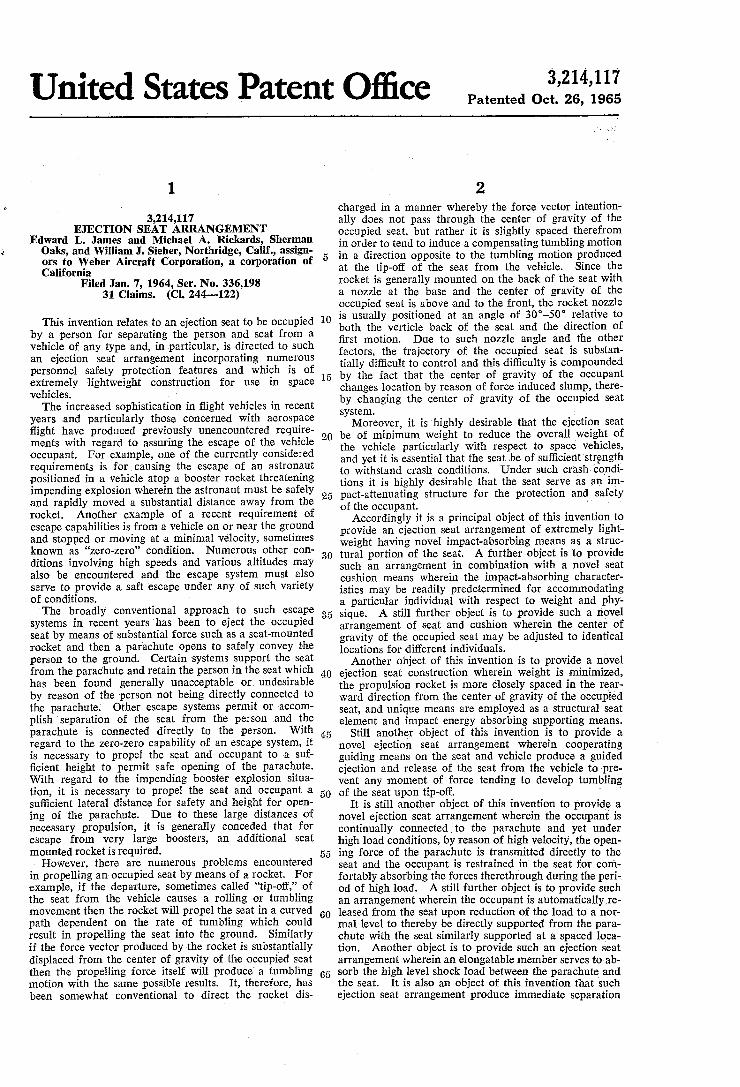
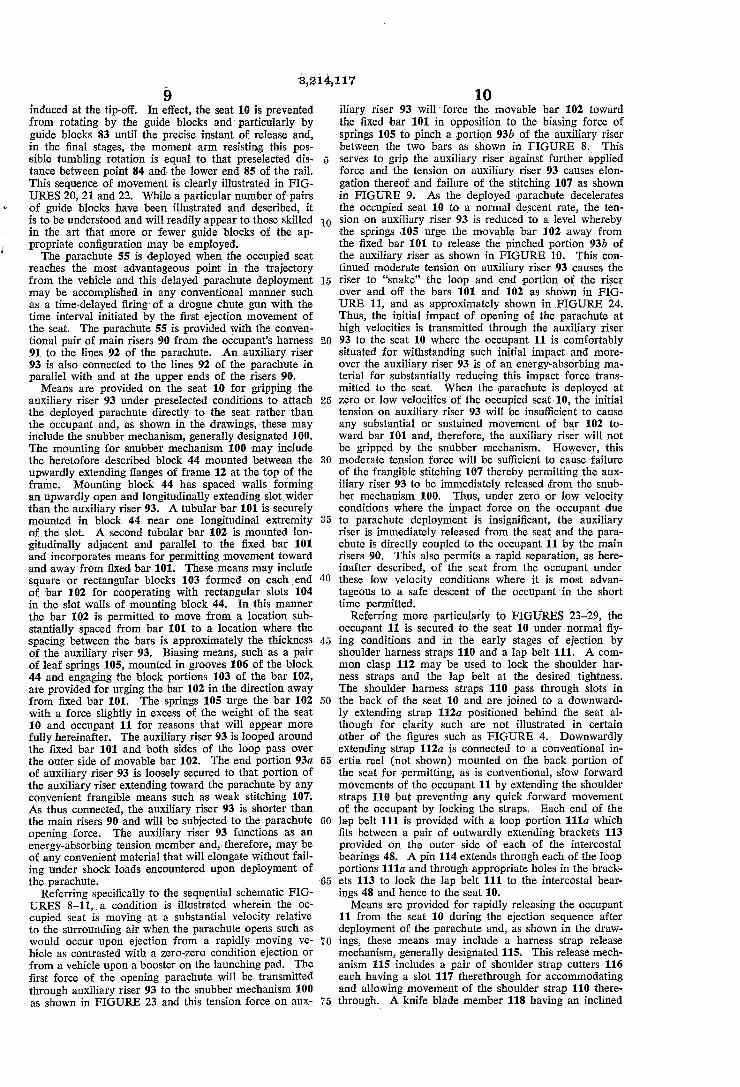
Other and more detailed objects and advantages of thls invention will appear from the following description and the accompanying drawings, wherein: FIGURE 1 is a perspective view of the ejection seat of
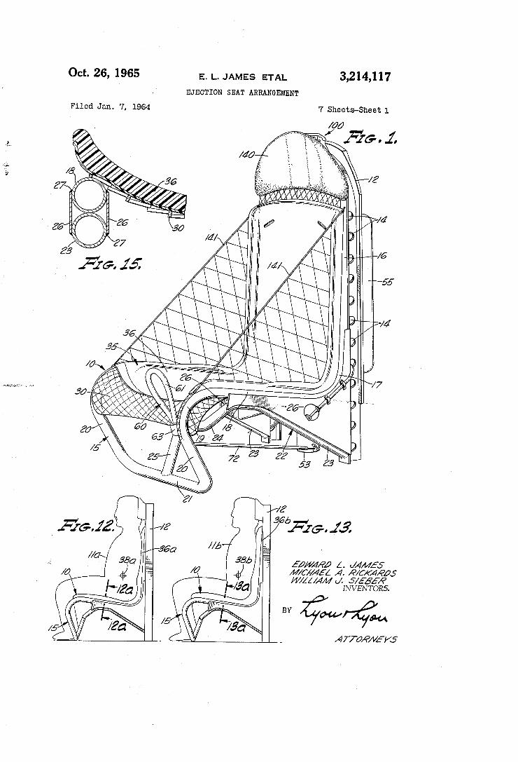
this invention with certain portions such as the lap belt and shoulder harness straps omitted for clarity. FIGURE 2 is a sectional side elevation view of the
ejection seat taken immediately in front of the lateral center of the seat. FIGURE 3 is a fragmentary front view of the ejection
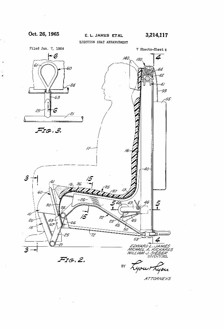
actuation mechanism for the seat taken substantially on the line 3—-3 of FIGURE 2. FIGURE 4 is a rear sectional elevation view taken sub
stantially on the line 4-4 of FIGURE 2. FIGURE 5 is a fragmentary sectional plan view taken
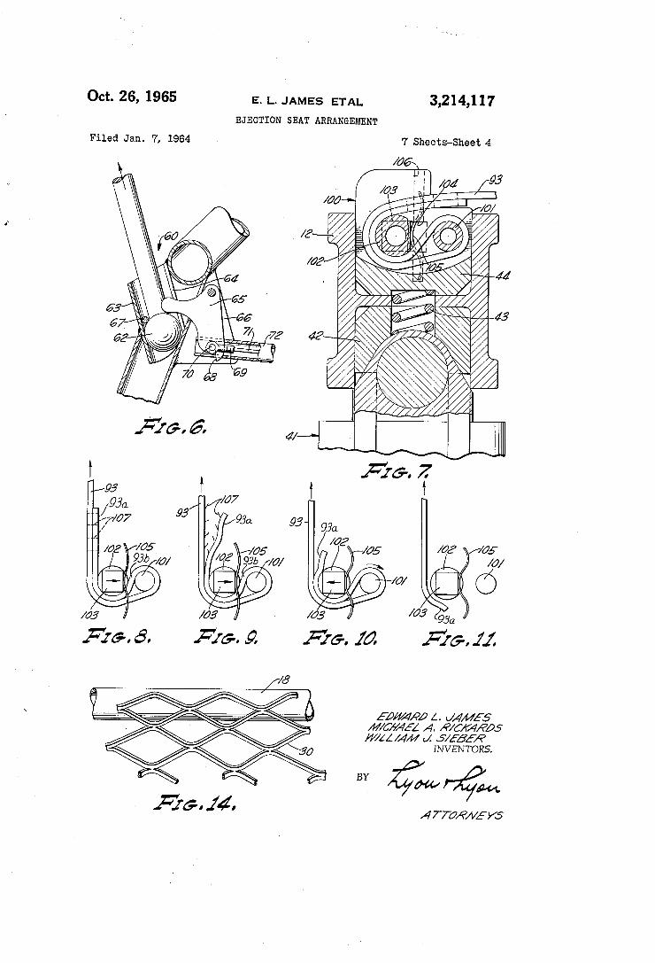
substantially on the line 5—5 of FIGURE 2 and illus trating the rocket and lap belt support yoke. FIGURE 6 is a fragmentary sectional elevation taken
substantially on the line 6—6 of FIGURE 3 and illus trating the ejection actuation mechanism. FIGURE 7 is a fragmentary sectional- elevation taken
substantially on the line 7—7 of FIGURE 4 and illustrating the snubber mechanism and rocket thrust connection. ‘
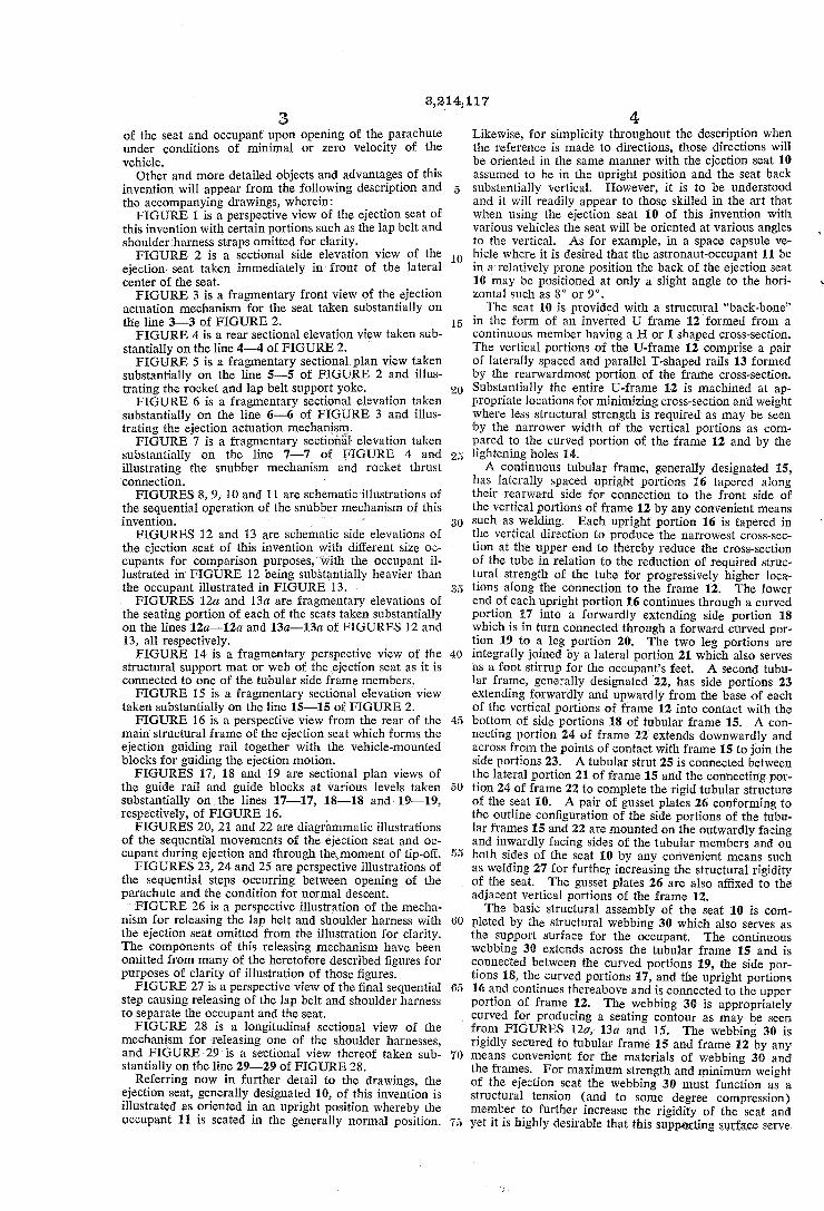
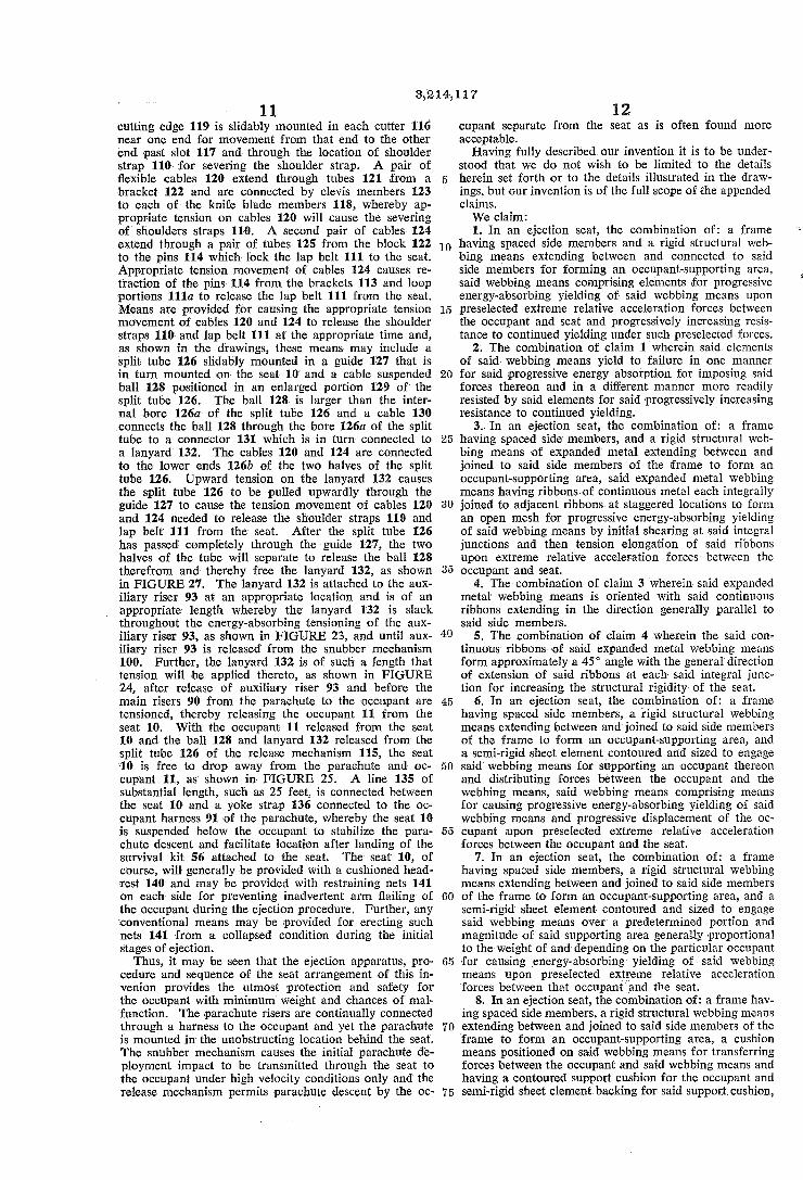
FIGURES 8, 9, l0 and 11 are schematic illustrations of the sequential operation of the snubber mechanism of this invention. ' '
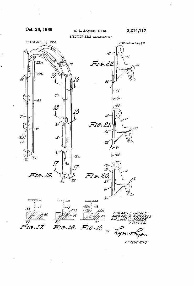
FIGURES 12 and 13 are schematic side elevations of the ejection seat of this invention with different size oc cupants for comparison purposes,'wi_th the occupant il lustrated in FIGURE 12 being substantially heavier than the occupant illustrated in FIGURE 13. FIGURES 12a and 13a are fragmentary elevations of
the seating portion of each of the seats taken substantially on the lines 12a—12a and 13a—13a of FIGURES l2 and 13, all respectively. ~ FIGURE 14 is a fragmentary perspective view of the
structural support mat or web of the ejection seat as it is connected to one of the tubular side frame members. FIGURE 15 is a fragmentary sectional elevation view
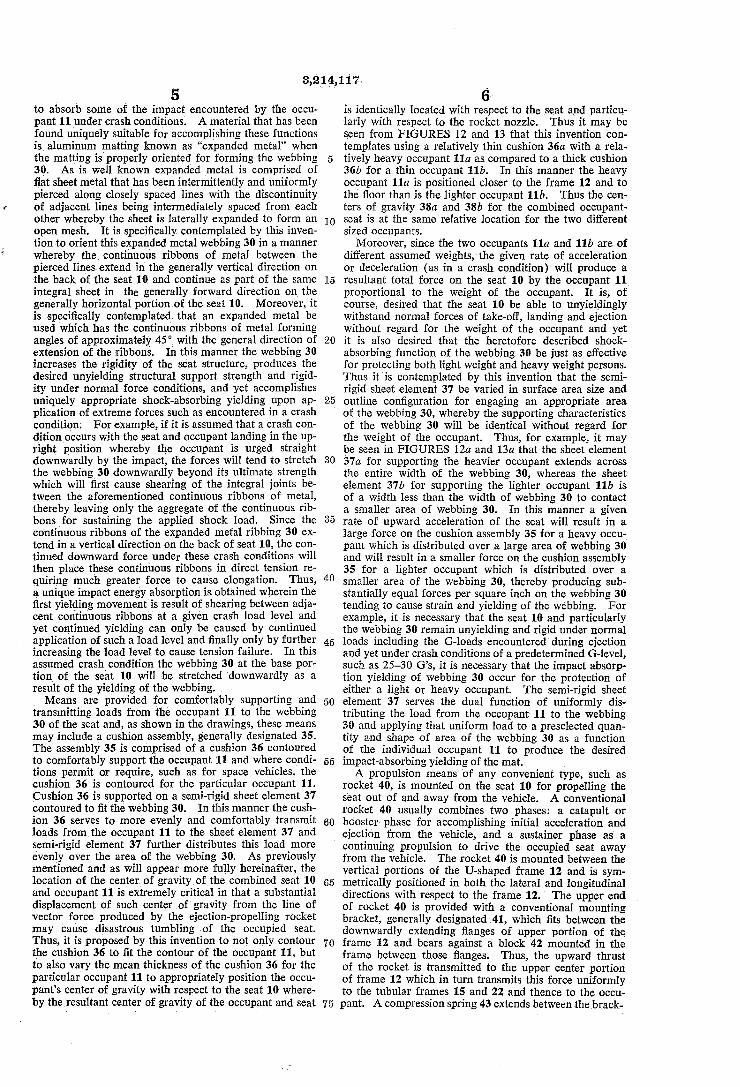
taken substantially on the line 15—15 of FIGURE 2. FIGURE 16 is .a perspective view from the rear of the
main structural frame of the ejection seat which forms the ejection guiding rail together with the vehicle-mounted blocks for guiding the ejection motion. FIGURES 17, 18 and ‘19 are sectional plan views of
the guide rail and guide blocks at various levels taken substantially onthe lines 17-17, 18—18 and~19—19, respectively, of FIGURE 16. ' FIGURES 20, 21 and 22 are diagrammatic illustrations
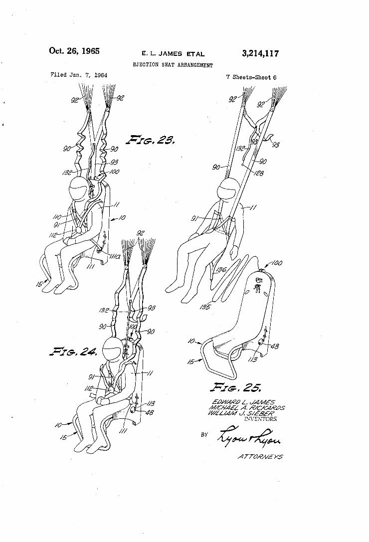
of the sequential movements of the ejection seat and oc cupant during ejection and through the. moment of tip-off. FIGURES 23, 24 and 25 are perspective illustrations of
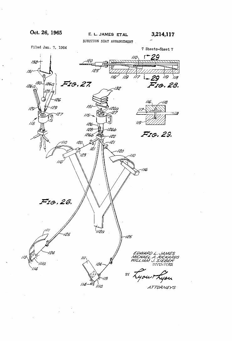
the sequential steps occurring between opening of the parachute and the condition for normal descent. FIGURE 26 is a perspective illustration of the mecha
nism for releasing the lap belt and shoulder harness with the ejection seat omitted from the illustration for clarity. The components of this releasing mechanism have been omitted from many of the heretofore described figures for purposes of clarity of illustration of those ?gures. FIGURE 27 is a perspective view of the ?nal sequential
step causing releasing of the lap belt and shoulder harness to separate the occupant and the seat. FIGURE 28 is a longitudinal sectional view of the
mechanism for releasing one of the shoulder harnesses, and FIGURE‘29 is a sectional view thereof taken sub stantially on the line 29—29 of FIGURE 28.
Referring now in further detail to the drawings, the ejection seat, generally designated 10, of this invention is illustrated as oriented in an upright position whereby the occupant 11 is seated in the generally normal position.
10
25
30
35
45
60
65
4 Likewise, for simplicity throughout the description when the reference is made to directions, those directions will be oriented in the same manner with the ejection seat 10 assumed to be in the upright position and the seat ‘back substantially vertical. However, it is to be understood and it will readily appear to those skilled in the art that when using the ejection seat 10 of this invention with various vehicles the seat will be oriented at various angles to the vertical. As for example, in a space capsule ve hicle where it is desired that the astronaut-occupant 11 be in a relatively prone position the back of the ejection seat 10 may be positioned at only a slight angle to the hori zontal such as 8“ or 9°. The seat 10 is provided with a structural “back-bone”
in the form of an inverted U frame 12 formed from a continuous member having a H or I shaped cross-section. The vertical portions of the U-frame 12 comprise a pair of laterally spaced and parallel T-shaped rails 13 formed by the rearwardmost portion of the frame cross-section. Substantially the entire U-frame 12 is machined at ap propriate locations for minimizing cross-section and weight where less structural strength is required as may be seen ‘by the narrower width of the vertical portions as com pared to the curved portion of the frame 12 and by the lightening holes 14. A continuous tubular frame, generally designated 15,
has laterally spaced upright portions 16 tapered along their rearward side for connection to the front side of the vertical portions of frame 12 by any convenient means such as welding. Each upright portion 16 is tapered in the vertical direction to produce the narrowest cross-sec tion at the upper end to thereby reduce the cross-section of the tube in relation to the reduction of required struc tural strength of the tube for progressively higher loca— tions along the connection to the frame 12. The lower end of each upright portion 16 continues through a curved portion 17 into a forwardly extending side portion 18 which is in turn connected through a forward curved por tion 19 to a leg portion 20. The two leg portions are integrally joined by a lateral portion 21 which also serves as a foot stirrup for the occupant’s feet. A second tubu lar frame, generally designated '22, has side portions 23 extending forwardly and upwardly from the base of each of the vertical portions of frame 12 into contact with the bottom of side portions 18 of tubular frame 15. A con necting portion 24 of frame 22 extends downwardly and across from the points of contact with‘ frame 15 to join the ‘side portions 23. A tubular strut 25 is connected between the lateral portion 21 of frame 15 and the connecting por tion 24 of frame 22 to complete the rigid tubular structure of the seat 10. A pair of gusset plates 26 conforming to the outline con?guration of the side portions of the tubu lar frames 15 and 22 are mounted on the outwardly facing and inwardly facing sides of the tubular members and on both sides of the seat 10 by any convenient means such as welding 27 for further increasing the structural rigidity of the seat. The gusset plates 26 are also a?‘ixed to the adjacent vertical portions of the frame 12. The basic structural assembly of the seat 10 is com
pleted by the structural webbing 30 which also serves as the support surface for the occupant. The continuous webbing 30 extends across the tubular frame 15 and is connected between the curved portions 19, the side por tions 18, the curved portions 17, and the upright portions 16 and continues thereabove and is connected to the upper portion of frame 12. The webbing 30 is appropriately
I curved for producing a seating contour as may be seen
70
from FIGURES 12a, 13a and 15. The webbing 30 is rigidly secured to tubular frame 15 and frame 12 by any means convenient for the materials of webbing 30 and‘. the frames. For maximum strength and minimum weight of the ejection seat the webbing 30 must function as a structural tension (and to some degree compression) member to further increase the rigidity of the seat and yet it is highly desirable that this supporting surface serve
3,214,117 5
to absorb some of the impact encountered by the occu pant 11 under crash conditions. A material that has been found uniquely suitable for accomplishing these functions is aluminum matting known as ‘fexpanded metal” when the matting is properly oriented for forming the webbing 30. As is well known expanded metal is comprised of flat sheet metal that has been intermittently and uniformly pierced along closely spaced lines with the discontinuity of adjacent lines being intermediately spaced from each other whereby the sheet is laterally expanded to form an open mesh. It is speci?cally contemplated by this inven tion to orient this expanded metal webbing 30 in a manner whereby the continuous ribbons of metal between the pierced lines extend in the generally vertical direction on the back of the seat 10 and continue as part of the same integral sheet in the generally forward direction on the generally horizontal portion of the seat 10. Moreover, it is speci?cally contemplated that an expanded metal be used which has the continuous ribbons of metal forming angles of approximately 45° with the general direction of extension of the ribbons. In this manner the webbing 30 increases the rigidity of the seat structure, produces the desired unyielding structural support strength and rigid ity under normal force conditions, and yet accomplishes uniquely appropriate shock-absorbing yielding upon ap plication of extreme forces such as encountered in a crash condition. For example, if it is assumed that a crash con dition occurs with the seat and occupant landing in the up right position whereby the occupant is urged straight downwardly by the impact, the forces will tend to stretch the webbing 30 downwardly beyond its ultimate strength which will ?rst cause shearing of the integral joints be tween the aforementioned continuous ribbons of metal, thereby leaving only the aggregate of the continuous rib bons for sustaining the applied shock load. Since the continuous ribbons of the expanded metal ribbing 30 ex tend in a vertical direction on the back of seat 10, the con tinued downward force under these crash conditions will then place these continuous ribbons in direct tension re quiring much greater force to cause elongation. Thus, a unique impact energy absorption is obtained wherein the ?rst yielding movement is result of shearing between adja cent continuous ribbons at a given crash load level and yet continued yielding can only be caused by continued application of such a load level and ?nally only by further increasing the load level to cause tension failure. In this assumed crash condition the webbing 30 at the base por tion of the seat 10 will be stretched downwardly as a result of the yielding of the webbing. Means are provided for comfortably supporting and
transmitting loads from the occupant 11 to the webbing 30 of the seat and, as shown in the drawings, these means may include a cushion assembly, generally designated 35. The assembly 35 is comprised of a cushion 36 contoured to comfortably support the occupant 11 and where condi tions permit or require, such as for space vehicles, the cushion 36 is contoured for the particular occupant l1. Cushion 36 is supported on a semi-rigid sheet element 37 contoured to ?t the webbing 30. In this manner the cush ion 36 serves to more evenly and comfortably transmit loads from the occupant 11 to the sheet element 37 and semi-rigid element 37 further distributes this load more evenly over the area of the webbing 30. As previously mentioned and as will appear more fully hereinafter, the location of the center of gravity of the combined seat 10 and occupant 11 is extremely critical in that a substantial displacement of such center of gravity from the line of vector force produced by the ejection-propelling rocket may cause disastrous tumbling of the occupied seat. Thus, it is proposed by this invention to not only contour the cushion 36 to ?t the contour of the occupant 11, but to also vary the mean thickness of the cushion 36 for the particular occupant 11 to appropriately position the occu pant’s center of gravity with respect to the seat 10 where by the resultant center of gravity of the occupant and seat
5
25
45
60
65
75
6. is identically located with respect to the seat and particu larly with respect to the rocket nozzle. Thus it may be seen from FIGURES 12 and 13 that this invention con templates using a relatively thin cushion 36a with a rela tively heavy occupant 11a as compared to a thick cushion 36b for a thin occupant 11b. In this manner the heavy occupant 11a is positioned closer to the frame 12 and to the ?oor than is the lighter occupant 11b. Thus the cen ters of gravity 38a and 38b for the combined occupant seat is at the same relative location for the two different sized occupants.
Moreover, since the two occupants 11a and 11b are of different assumed weights, the given rate of acceleration or deceleration (as in a crash condition) will produce a resultant total force on the seat 10 by the occupant 11 proportional to the weight of the occupant. It is, of course, desired that the seat 10 be able to unyieldingly withstand normal forces of take-off, landing and ejection without regard for the weight of the occupant and yet it is also desired that the heretofore described shock absorbing function of the webbing 30 be just as effective for protecting both light weight and heavy weight persons. Thus it is contemplated by this invention that the semi rigid sheet element 37 be varied in surface area size and outline con?guration for engaging an appropriate area of the webbing 30, whereby the supporting characteristics of the webbing 30 will be identical without regard for the weight of the occupant. Thus, for example, it may be seen in FIGURES 12a and 13a that the sheet element 37a for supporting the heavier occupant extends across the entire width of the webbing 30, whereas the sheet element 37b for supporting the lighter occupant 11b is of a width less than the width of webbing 30 to contact a smaller area of webbing 30. In this manner a given rate of upward acceleration of the seat will result in a large force on the cushion assembly 35 for a heavy occu pant which is distributed over a large area of webbing 30 and will result in a smaller force on the cushion assembly 35 for a lighter occupant which is distributed over a smaller area of the webbing 30, thereby producing sub stantially equal forces per square inch on the webbing 30 tending to cause strain and yielding of the webbing. For example, it is necessary that the seat 10 and particularly the webbing 30 remain unyielding and rigid under normal loads including the G-loads encountered during ejection and yet under crash conditions of a predetermined G-level, such as 25-30 G’s, it is necessary that the impact absorp tion yielding of webbing 30 occur for the protection of either a light or heavy occupant. The semi-rigid sheet element 37 serves the dual function of uniformly dis tributing the load from the occupant 11 to the webbing 30 and applying that uniform load to a preselected quan tity and shape of area of the webbing 30 as a function of the individual occupant 11 to produce the desired impact-absorbing yielding of the mat. A propulsion means of any convenient type, such as
rocket 40, is mounted on the seat 10 for propelling the seat out of and away from the vehicle. A conventional rocket 40 usually combines two phases: a catapult or booster phase for accomplishing initial acceleration and ejection from the vehicle, and a sustainer phase as a continuing propulsion to drive the occupied seat away from the vehicle. The rocket 40 is mounted between the vertical portions of the U-shaped frame 12 and is sym metrically positioned in both the lateral and longitudinal directions with respect to the frame 12. The upper end of rocket 40 is provided with a conventional mounting bracket, generally designated 41, which ?ts between the downwardly extending ?anges of upper portion of the frame 12 and bears against a block 42 mounted in the frame between those ?anges. Thus, the upward thrust of the rocket is transmitted to the upper center portion of frame 12 which in turn transmits this force uniformly to the tubular frames 15 and 22 and thence to the occu pant. A compression spring 43 extends between the brack
3,214,117 7
et 41 and‘ a mounting block 44 which is secured to the frame 12. In mounting the seat 10 in the vehicle with the rocket 403 in place, the compression spring 43 is com pressed to exert a moderate force, say approximately 50 lbs. and the bracket 41 ?rmly contacts the block 42. As will hereinafter appear more fully, the rocket 40 is not ?rmly secured to the seat 10 and therefore when the rocket is completely spent the compression spring 43 will urge the rocket away from frame 12 thereby jettisoning the burned-out rocket. In this manner the occupant 11 is protected from sustained temperature increases if he remains in the seat 10 through choice or malfunction. A support yoke assembly, generally designated 45,
assists in transmitting the propulsion forces from the rocket 40 to the seat 10 and in supporting the rocket on the seat. Support yoke assembly 45 includes a half collar 46‘ for engaging the rocket 40, a pair of forwardly and outwardly extending tubular members 47 connected at one end to intercostal bearings 48, and a shield gusset 49. The intercostal bearings 48'are appropriately mounted in the ?ange plates 26 on each side of the seat 10 for pivotal movement about a horizontal lateral axis. The shield gusset 49' extends between the tubular members 47 and is secured thereto for forming a rigid assembly. The shield gusset 49 is provided with a lower de?ecting surface 50 serving as a barrier between the occupied seat and the nozzle of the rocket to de?ect burning particles that may otherwise present a hazard. A pair of struts 51 extends upwardly and outwardly from the half collar 46 and are joined‘ to the framev 12'. A pair of similar struts 52 ex tends downwardly and outwardly and are connected to the frame 12. Struts 51 and 52 serve to reinforce the support assembly 45 and prevent inadvertent pivotal move ment thereof. However, struts 51 and 52' are of a strength for readily failing under crash conditions wherein the webbing 30 is elongated downwardly under the force of the occupant 11 and in this way upon contact the support assembly 45 pivots downwardly for continued unimpaired yielding of the webbing 30. The struts 51 fail in tension and the struts 52 fail under column loading. As pre viously noted, the nozzle of the rocket 40 positioned at the base 53 of the rocket will be directed in a rearward and downward direction whereby a vforward and upward force will‘ be applied to the seat 10. It may be seen that the upward force will be transmitted to the frame 12 at the upper end of the rocket and the forward thrust force will be transmittedv to the‘ seat by the support assembly 45. Since the rocket 40 is immediately behind the webbing 30 forming the back of the seat, the rocket nozzle is at a minimum longitudinal distance behind the center of gravity of the occupied seat, thereby minimizing the angular displacement of the nozzle from the vertical. This further minimizes the heretofore mentioned induced errors caused by the slump of the center of gravity of the occupant under ejection forces. Moreover, the para chute 55 is mounted on the back of the seat on one side of the rocket 40 and the conventionally supplied survival kit 56 is mounted on the back of the seat on the other side of rocket 40. Thus, the parachute and the survival kit are actually positioned to the rear of the center line of rocket‘ 40 thereby further moving the center of gravity of the occupied seat in a rearward direction. Means are provided for initiating the ejection of the
occupied seat 10 from the vehicle and these means may include the D-handle assembly, generally designated 60, mounted in the forward portion of the seat as best shown in FIGURES 3 and 6. A conveniently shaped handle 61 has a ball member 62 mounted on the lower end there of which is positioned in a tubular member 63 mounted on the seat frame. A lever 65 is pivotally mounted on a bracket 66 on the tubular frame 22 and extends through a slot 64 in member 63 to a position above ball 62. A shear pin 67 is mounted in tubular member 63 above the ball 62. In order to initiate the ejection an upward tforce must be applied on handle 61 of su?icient mag
10
15
8 nitude to shear the pin 67 thereby permitting the ball to engage and pivot the lever 65. While ball 62 ?ts close ly within tubular member 63, the handle 61 ?ts loosely within tubular member 63 thereby permitting the oc cupant 11 to pull upwardly on handle 61 in a range of directions with equal success. A second or locking pin (not shown) may be provided similar to shear pin 67 but of greater strength for preventing inadvertent actua tion of the ejection mechanism by reason of a force ap plied to handle 61 of any magnitude. Such a locking pin would be removed after the occupant is positioned in the seat 10 and before ?ight. The lever 65 is provided with a downwardly extending slot 68 and a clevis member 69 ?ts over this portion of lever 65 and has a pin 70 en gaging the slot 68. Clevis member 69 is connected to a cable 71 which extends rearwardly and is connected to the rocket ignition means and seat-locking means (not shown). The pivoting of lever 65 by lifting of handle 61 pulls cable 71 thereby releasing the seat 10 from the vehicle and igniting the rocket 40. A tube 72 surrounds the cable 71 for preventing inadvertent ignition of the rocket by snagging or pulling of the cable. Further, inadvertent actuation of the rocket under a crash condi tion is prevented by the slot and pin arrangement be tween lever 65 and clevis 69, whereby downward force on the tube 72 will merely cause the clevis 69 to be released from the lever 65. This‘ frees‘ the cable 71 and prevents actuation as might otherwise be caused by the downward movement of the occupant 11 through the yielding of the impact-absorbing webbing 30.
Means are provided for supporting the seat 10 within the vehicle and guiding the ejection motion of the seat 10 out of the vehicle and, as shown in the drawings, these means may include a plurality of pairs of guide blocks 80, 81, 82 and 83 mounted on the vehicle struc ture with one of each pair engaging each of the vertical rails 13 of the frame 12. The outwardly extending one half 13a of the ?ange of each rail 13 terminates at point 84 at a preselected distance from the bottom 85 of the rail. Thus the lowermost guide block 80 is provided with only an inwardly extending L-shaped- slot 86 for accommodating the inwardly extending one-half 13b of the ?ange of the rail 13. Each of the guide blocks 81 and 82 may be substantially the ‘same and each is provided with a T-shaped slot 87 for slidably engaging the rail
' 13. Guide blocks 81 and 82 are vertically spaced from
60
65
one another and from block 80 in the vertical direction to provide uniform support. Guide blocks 83 are of sub stantial vertical length‘ and are positioned adjacent the upper extremity of the rails 13. Guide blocks 83 have a lower portion 83a with a T-shaped slot 88 and an upper portion 83b having an outwardly extending slot 89 for engaging only the outwardly extending half ?anges 13a, the outer surface of the web of rail 13, and the rear war-dly facing surface of rail 13. Thus, the inwardly fac ing portion of the upper portion 83b of each of the guide blocks 83 is unobstructed for accommodating the inwardly and upwardly curving portions of the frame 12. The upper portion 83b is of a vertical length substan tially identical to the preselected distance between the termination point 84 of half ?ange 13a and the lower extremity 85 of the frame. In this manner, the catapulting movement of the seat 10 relative to the vehicle is guided by the guide blocks 80, 81, 82 and 83 from inception to the moment of tip-off. Just prior to tip-01f the outer half ?ange 13a of each rail at the point 84 is still engaged in the slot 89 of the upper portion 83b of guide block 83, and the lower extremity of the inner half ?ange 13b of the rail is engaged‘ in the T-slot 88 of the lower por tion 83a of guide block 83. This interengagement of half ?ange 13a with slot 89 and half ?ange 13b with slot 88 terminates at precisely the same position of movement due to the predetermined cooperating lengths and thus the occupied seat 10 moves away from the vehicle in rectilinear motion and without a tumbling rotation being
“3,214,117 9
induced at the tip-01f. In effect, the seat 10 is prevented from rotating by the guide blocks and particularly by guide blocks 83 until the precise instant of release and, in the ?nal stages, the moment arm resisting this pos sible tumbling rotation is equal to that preselected dis tance between point 84 and the lower end 85 of the rail. This sequence of movement is clearly illustrated in FIG URES 20, 21 and 22. While a particular number of pairs of guide blocks have been illustrated and described, it is to be understood and will readily appear to those skilled in the art that more or fewer guide blocks of the ap propriate con?guration may be employed. The parachute 55 is deployed when the occupied seat
reaches the most advantageous point in the trajectory from the vehicle and this delayed parachute deployment may be accomplished in any conventional manner such as a time-delayed ?ring of a drogue chute gun with the time interval initiated by the ?rst ejection movement of the seat. The parachute 55 is provided with the conven tional pair of main risers 90 from the occupant’s harness 91 to the lines 92 of the parachute. An auxiliary riser 93 is also connected to the lines 92 of the parachute in parallel with and at the upper ends of the risers 90. Means are provided on the seat 10 for gripping the
auxiliary riser 93 under preselected conditions to attach the deployed parachute directly to the seat rather than the occupant and, as shown in the drawings, these may include the snubber mechanism, generally designated 100. The mounting for snubber mechanism 100 may include the heretofore described block 44 mounted between the upwardly extending ?anges of frame 12 at the top of the frame. Mounting block 44 has spaced walls forming an upwardly open and longitudinally extending slot wider than the auxiliary riser 93. A tubular bar 101 is securely mounted in block 44 near one longitudinal extremity of the slot. A second tubular bar 102 is mounted lon gitudinally adjacent and parallel to the ?xed bar 101 and incorporates means for permitting movement toward and away from ?xed bar 101. These means may include square or rectangular blocks 103 formed on each end of bar 102 for cooperating with rectangular slots 104 in the slot walls of mounting block 44. In this manner the bar 102 is permitted to move from a location sub stantially spaced from bar 101 to a location where the spacing between the bars is approximately the thickness of the auxiliary riser 93. Biasing means, such‘as a pair of leaf springs 105, mounted in grooves 106 of the block 44 and engaging the block portions 103 of the bar 102, are provided for urging the bar 102 in the direction away from ?xed bar 101. The springs 105 urge the bar 102 with a force slightly in excess of the weight of the seat 10 and occupant 11 for reasons that will appear more fully hereinafter. The auxiliary riser 93 is looped around the ?xed bar 101 and both sides of the loop pass over the outer side of movable bar 102. The end portion 93a of auxiliary riser 93 is loosely secured to that portion of the auxiliary riser extending toward the parachute by any convenient frangible means such as weak stitching 107. As thus connected, the auxiliary riser 93 is shorter than the main risers 90 and will be subjected to the parachute opening force. The auxiliary riser 93 functions as an energy-absorbing tension member and, therefore, may be of any convenient material that will elongate without fail ing under shock loads encountered upon deployment of the parachute.
Referring speci?cally to the sequential schematic FIG URES 8-11, a condition is illustrated wherein the oc cupied seat is moving at a substantial velocity relative to the surrounding air when the parachute opens such as would occur upon ejection from a rapidly moving ve hicle as contrasted with a zero-zero condition ejection or from a vehicle upon a booster on the launching pad. The ?rst force of the opening parachute will be transmitted through auxiliary riser 93 to the snubber mechanism 100 as shown in FIGURE 23 and this tension force onjaux
25
30
45
65
70
75
10 iliary riser 93 will force the movable bar 102 toward the ?xed bar 101 in opposition to the biasing force of springs 105 to pinch a portion 93b of the auxiliary riser between the two bars as shown in FIGURE 8. This serves to grip the auxiliary riser against further applied force and the tension on auxiliary riser 93 causes elon gation thereof and failure of the stitching 107 as shown in FIGURE 9. As the deployed parachute decelerates the occupied seat 10 to a normal descent rate, the ten~ sion on auxiliary riser 93 is reduced to a level whereby the springs -105 urge the movable bar 102 away from the ?xed bar 101 to release the pinched portion 93b of the auxiliary riser as shown in FIGURE 10. This con tinued moderate tension on auxiliary riser 93 causes the riser to “snake” the loop and end portion of the riser over and off the bars 101 and 102 as shown in FIG URE 11, and as approximately shown in FIGURE 24. Thus, the initial impact of opening of the parachute at high velocities is transmitted through the auxiliary riser 93 to the seat 10 where the occupant 11 is comfortably situated for withstanding such initial impact and more over the auxiliary riser 93 is of an energy-absorbing ma terial for substantially reducing this impact force trans mitted to the seat. When the parachute is deployed at zero or low velocities of the occupied seat 10, the initial tension on auxiliary riser 93 will be insufficient to cause any substantial or sustained movement of bar 102 to ward bar 101 and, therefore, the auxiliary riser will not be gripped by the snubber mechanism. However, this moderate tension force will be sufficient to cause failure of the frangible stitching 107 thereby permitting the aux iliary riser 93 to be immediately released ‘from the snub ber mechanism 100. Thus, under zero or low velocity conditions where the impact force on the occupant due to parachute deployment is insigni?cant, the auxiliary riser is immediately released from the seat and the para chute is directly coupled to the occupant 11 by the main risers 90. This also permits a rapid separation, as here inafter described, of the seat from the occupant under these low velocity conditions where it is most advan tageous to a safe descent of the occupant in the short time permitted. ‘
Referring more particularly to FIGURES 23-29, the occupant 11 is secured to the seat 10 under normal ?y~ ing conditions and in the early stages of ejection by shoulder harness straps 110 and a lap belt 111. A com mon clasp 112 may be used to lock the shoulder har ness straps and the lap belt at the desired tightness. The shoulder harness straps 110 pass through slots in the back of the seat 10 and are joined to a downward ly extending strap 112a positioned behind the seat al though for clarity such are not illustrated in certain other of the ?gures such as FIGURE 4. Downwardly extending strap 112a is connected to a conventional in ertia reel (not shown) mounted on the back portion of the seat for permitting, as is conventional, slow forward movements of the occupant 11 by extending the shoulder straps 110 but .preventing any quick forward movement of the occupant by locking the straps. Each end of the lap belt 111 is provided with a loop portion 111a which ?ts between a pair of outwardly extending brackets 113 provided on the outer side of each of the intercostal bearings 48. A pin 114 extends through each of the loop portions 111a and through appropriate holes in the brack ets 113 to lock the lap belt 111 to the intercostal bear ings 48 and hence to the seat 10. Means are provided for rapidly releasing the occupant
11 from the seat 10 during the ejection sequence after deployment of the parachute and, as shown in the draw ings, these means may include a harness strap release mechanism, generally designated 115. This release mech anism 115 includes a pair of shoulder strap cutters 116 each having a slot 117 therethrough for accommodating and allowing movement of the shoulder strap 110 there through. A knife blade member 118 having an inclined
3,214,117 11
cutting edge 119 is slidably mounted in each cutter 116 near one end for movement from that end to the other end past slot 117 and through the location of shoulder strap 110 for severing the shoulder strap. A pair of ?exible ‘cables 120 extend through tubes 121 from a bracket 122 and- are connected by clevis members 123 to each of the knifev blade members 118, whereby ap propriate tension on cables 120 will cause the severing of shoulders straps 110. A second pair of cables 124 extend through a pair of tubes 125 from the block 122 to the pins 114 which lock the lap belt 111 to the seat. Appropriate tension movement of cables 124 causes re traction of the pins 114 from the brackets 113 and loop portions 111a to release the lap belt 111 from the seat. Means are provided for causing the appropriate tension movement of cables 120 and 124 to release the shoulder straps 110' and lap belt 111 at the appropriate time and, as shown in the drawings, these means may include a split tube 126 slidably mounted in a guide 127 that is in turn mounted on- the seat 10‘ and a cable suspended ball 128 positioned in an enlarged portion 129 of the split tube 126. The ball 128 is larger than the inter nal bore 126a of the split tube 126 and a cable 130 connects the ball 128 through the bore 126a of the split tube to a connector 131 which is in turn connected to a lanyard 132. The cables 120 and 124 are connected to the lower ends 126!) of the two halves of the split tube 126. Upward tension on the lanyard 132 causes the split tube 126 to be pulled upwardly through the guide 127 to cause the tension movement of cables 120 and 124 needed to release the shoulder straps 110 and lap belt 111 from the seat. After the split tube 126 has passed completely through the'guide 127, the two halves of the tube will separate to release the ball 128 therefrom and thereby free the lanyard 132, as shown in FIGURE 27. The lanyard 132 is attached to the aux iliary riser 93 at an appropriate location and is of an appropriate‘ length whereby the lanyard 132 is slack throughout the energy-absorbing tensioning of the aux iliary riser 93, as shown in FIGURE 23, and until aux iliary riser 93 is released: from the snubber mechanism 100. Further, the lanyard 132 is of such a length that tension will be applied thereto, as shown in FIGURE 24, after release of auxiliary riser 93 and before the main risers 90 from the parachute to the occupant are tensioned, thereby releasing the occupant 11 from the seat 10. With the occupant 11 released from the seat 10 and the ball 128 and lanyard 132 released from the split tube 126 of the release mechanism 115, the seat 10 is free to drop away from the parachute and oc cupant 11, as shown in- FIGURE 25. A line 135 of substantial length, such as 25 feet, is connected between the seat 10 and a yoke strap 136 connected to the oc cupant harness 91 of the parachute, whereby the seat 10 is suspended below the ‘occupant to stabilize the para chute descent and- facilitate location after landing of the survival kit 56 attached to the seat. The seat‘ 10, of course, will generally be provided with a cushioned head rest 140 and may be provided with restraining nets 141 on each side for preventing inadvertent arm ?ailing of the occupant during the ejection procedure. Further, any “conventional means may be provided ‘for erecting such nets 141 ‘from a collapsed condition during the initial stages of ejection‘.
Thus, it may be seen that the ejection apparatus, pro cedure and sequence of the seat arrangement of this in venion provides the utmost protection and safety for the occupant with minimum weight and chances of mal function. The parachute risers are continually connected through a harness to the occupant and yet the parachute is mounted in the unobstructing location behind the seat. The snubber mechanism causes the initial parachute de ployment impact to be transmitted through the seat to the occupant under high velocity conditions only and‘ the release mechanism permits parachute descent by the oc
20
0
30
40
45
50
55
60
65
70
cupant separate from the seat as is often found more acceptable. Having fully described our invention it is to be under
stood that we do not wish to be limited to the details herein set forth or to the details illustrated in the draw ings, but our invention is ‘of the full scope of the appended claims. We claim: .
1. In an ejection seat, the combination of: a frame having spaced side members and a rigid structural web bing means extending between and connected to said side members for forming an occupant-supporting area, said webbing means comprising elements for progressive energy-absorbing yielding of said webbing means upon preselected extreme relative acceleration forces between the occupant and seat and progressively increasing resis tance to continued yielding under such preselected forces.
2. The combination of claim 1 wherein said elements of said webbing means yield to failure in one manner for said progressive energy absorption for imposing said forces thereon and in a different manner more readily resisted by said elements for said progressively increasing resistance to continued yielding.
3.- In an ejection seat, the combination of: a frame having spaced side members, and a rigid structural web bing means of expanded metal extending between and joined to said side members of the frame to form an occupant-supporting area, said expanded metal webbing means having ribbonsof continuous metal each integrally joined to adjacent ribbons at staggered locations to form an open mesh for progressive energy-absorbing yielding of said webbing means by initial shearing at said integral junctions and then tension elongation of said ribbons upon extreme relative acceleration forces between the occupant and seat.
4. The‘ combination of claim 3 wherein said expanded metal webbing means is oriented with said continuous ribbons extending in the direction generally parallel to said side members.
5. The combination of claim 4 wherein the said con tinuous ribbons of said expanded metal webbing means form approximately a 45° angle with the general'direction of extension of said ribbons at each- said integral junc tion for increasing the structural rigidity of the seat.
6. In an ejection seat, the combination of: a frame having spaced side members, a rigid structural webbing means extending between and joined to said side members of the frame to form an occupant-supporting area, and a semi-rigid sheet element contoured and sized to engage said webbing means for supporting an occupant thereon and distributing forces between the occupant and the webbing means, said webbing means comprising means for ‘causing progressive energy-absorbing yielding of said webbing means and progressive displacement of the oc cupant upon preselected extreme relative acceleration forces between the occupant and the seat.
7. In an ejection seat, the combination of: a frame having spaced side members, a rigid structural webbing means extending between and joined to said side members of the frame to form‘ an occupant-supporting area, and a semi-rigid‘ sheet element contoured and sized to engage said webbing means over a predetermined portion and magnitude of said supporting area generally proportional to the weight of and depending’ on the particular occupant ‘for causing energy-absorbing yielding of said webbing means upon preselected extreme relative acceleration forces between that occupant and the seat.
8. In an ejection seat, the combination of: a frame hav ing spaced side members, a rigid structural webbing means extending between and joined to said side members of the frame to form an occupant-supporting area, a cushion means positioned on said webbing means for transferring forces between the occupant and said webbing means and having a contoured support cushion for the occupant and semi-rigid sheet element. backing for said support. cushion,
3,214,117 13
and said sheet element contoured and sized to engage said webbing means over a predetermined magnitude of said supporting area generally proportional to the weight of the particular occupant for causing energy-absorbing yield ing of said webbing means upon preselected extreme rela tive acceleration forces between that occupant and the seat.
9. In an ejection seat, the combination of: a frame hav ing spaced side members, a rigid structural webbing means extending between and joined to said side members of the frame to form an occupant-supporting area, a cushion means positioned on said webbing means for transferring forces between the occupant and said webbing means and having a contoured support cushion for a particular occu Pam, and a semi-rigid sheet element backing for said sup port cushion, said contoured support cushion having a shape and mean thickness for properly positioning that occupant’s center of gravity to locate the center of gravity of the occupied seat at a preselected point relative to said frame, and said semi-rigid sheet element contoured and sized to engage said webbing means for causing energy absorbing yielding of said webbing means upon substan tial relative acceleration forces between the person and the seat. '
10. In an ejection seat for an occupant, the combination of: an inverted U-shaped back frame having a generally continuous I-beam cross-section, a tubular frame having laterally spaced side members joined to and along said back frame and extending forward and then downward and together as an integral unit, a structurally rigid web bing means extending between and joined to said side members of the tubular frame to form a supporting area, a cushion means positioned on said webbing means for transferring forces between the occupant and said web bing means, and said cushion means having a semi-rigid sheet element contoured and sized to engage said webbing means over a predetermined portion and magnitude of said supporting area generally proportional to the weight of the particular occupant for causing energy-absorbing yielding of said webbing means upon preselected extreme relative acceleration forces between the person and seat.
11. “In an ejection seat for an occupant, the combina tion of: an inverted U-shaped back frame having a gen erally'continuous I-beam cross-section, said back frame having thinned vertical portions spaced the width of the seat and a heavy curved upper section, a rocket mounted between said back frame having vertical portions and en gaging said upper section for transmitting thrust to said upper section, a tubular frame having laterally spaced side members joined to and along said back frame and extend ing forward and then downward and together as an inte gral unit, a structurally rigid Webbing means extending be tween and joined to said side members of the tubular frame to form a supporting area, a cushion means posi tioned on said webbing means for transferring forces be tween the occupant and said Webbing means, and said cushion means having a semi-rigid sheet element con toured and sized to engage said webbing means over a predetermined portion and magnitude of said supporting area generally proportional to the weight of the particular occupant for causing energy-absorbing yielding of said webbing means upon preselected extreme relative accel eration forces between the person and seat.
12.‘ The ‘combination of claim 11 wherein biasing means are mounted and compressed between said rocket and said upper section of the back frame for jettisoning ; said rocket upon termination of the thrust.
13. In an ejection seat arrangement for use by a person ‘in rapidly departing from a vehicle, the combination of: ,a seat structure having an inverted U-shaped back frame , and means for supporting the person in a seated position including a rigid webbing means forming a supporting
I area, a semi-rigid sheet element contoured and sized to en gage said webbing means for supporting the person there _on and distributing forces between the person and said
10
25
30
45
50
55
60
65
70
75
14 webbing means, said back frame having a pair of laterally spaced vertical rails, each said rail having a modi?ed por tion at the lower end of a predetermined length with part of the rail removed and another part remaining, guide block means for mounting on the vehicle and having means for slidably engaging said rails to guide vertical movement of said seat structure, a release guide block engaging each rail above said guide block means and mounted on the vehicle, and each release guide block hav ing a lower portion for engaging the entire rail and an upper portion equal to said predetermined length, said upper portion of each release guide block having means for engaging only that said remaining part of the lower end of the rail for releasing the lower portions of the rails by said release guide blocks at two vertically spaced loca tions simultaneously upon vertical movement of the seat structure relative to the vehicle.
14. In an ejection seat arrangement for use by an oc cupant in rapidly departing from a vehicle, the combina tion of: a seat structure having an inverted U-shaped back frame, a tubular frame having laterally spaced side members joined to and along said back frame and extend ing forward and then downward and together as an inte gral unit, a structurally rigid webbing means extending be tween and joined to said side members of the tubular frame to form a supporting area, a cushion means posi tioned on said webbing means for transferring forces be tween the occupant and said webbing means, said cushion means having a semi-rigid sheet element contoured and sized to engage said webbing means over a predetermined portion and magnitude of said supporting area generally proportional to the weight of the particular occupant for causing energy-absorbing yielding of said webbing means upon preselected relative acceleration forces between the person and seat, said U-shaped back frame having a pair of laterally spaced vertical rails at the rear, each said rail having a modi?ed portion at the lower end of a predetermined length with part of the rail removed and another part remaining, guide block means for mounting on the vehicle and having means for slidably engaging said rails to guide vertical movement of said seat struc ture, a release guide block engaging each rail above said guide block means and mounted on the vehicle, and each release guide block having a lower portion for engaging the entire rail and an upper portion equal to said pre determined length, said upper portion of each release guide block having means for engaging only that said re maining part of the lower end of the rail for releasing the ‘lower portions of the rails by said release guide blocks at two vertically spaced locations simultaneously upon ver tical movement of the seat structure relative to the vehicle.
15. In an ejection seat arrangement for use by a per son in rapidly departing from a vehicle, the combination of: a seat structure having means for supporting the person in a seated position, said seat structure having a pair of laterally spaced vertical rails on the back, each said rail having a modi?ed portion removed at the lower end of a predetermined length with part of the rail re moved and another part remaining, guide block means for mounting on the vehicle and having means for slidably engaging said rails to guide vertical movement of said seat structure, a release guide block engaging each rail above said guide block means and mounted on the vehicle, and each release guide block having a lower portion for engag ing the entire rail and an upper portion equal to said pre determined length, said upper portion of each release guide block having means for engaging only that said remaining part of the lower end of the rail for releasing the lower portions of the rails by said release guide blocks at two vertically spaced locations simultaneously upon vertical movement of the seat structure relative to the vehicle.
16. In an ejection seat arrangement for use by a per son in rapidly departing from a vehicle, the combination of: a seat structure having means for supporting the per
3,214,117’
son, said seat structure having a pair of laterally spaced vertical rails on the back, said rails each having a gener ally T-‘shaped cross-sectional portion, one-half of the ?ange of'each said rail continuing downwardly at the lower end of said rails a predetermined length beyond the'termination of the other one-half of the ?ange, guide block means for mounting on the vehicle and having T slot means for slidably engaging said rails to guide verti cal movement of said seat structure, a release guide block engaging each rail above said guide block means and mounted on the vehicle, and each release guide block having a lower portion. with a T-slot for engaging both halves of the rail‘ ?ange and an upper portion extending upward therefrom a distance equal to said predeter mined length, said upper portion of each release guide block having means for engaging only the said other one-half of the rail ?ange for releasing the lower ex tremity _of the said other one-half of the ?ange upon vertical movement of the seat structure relative to the ve hicle at the same moment as the release of the longer one-half of the rail ?ange from the T-slot of the said lower portion of the release guide block.
17. In an ejection seat arrangement for use by a per; son in rapidly departing from a vehicle, the combination of: a seat structure having means for supporting the person, said seat structure having a pair of laterally spaced vertical rails on the back, said rails each having a generally T-shaped cross-sectional portion at the rear oriented wth the upper flange of the T having one-half extending inwardly toward the other rail and the other half extending outwardly, said inwardly extending one half of the ?ange of each said. rail ‘continuing downwardly at the lower end of said rails a predetermined length be yond the termination of each said outwardly extending half of the ?ange, guide block means for mounting on the vehicle and having T-slot means for slidably engaging said T-shaped portion of said rails to guide vertical move ment of said seat structure, a release guide‘ block engag ing each rail above said guide block means and mounted on the vehicle, and each release guide block having a lower portion with a T-slot for engaging both halves of the rail ?ange and an upper portion extending upward therefrom a distance equal to said predetermined length, said upper portion of each release guide block having an inwardly facing slot for engaging only the outwardly ex tending. half of the rail ?ange for releasing the lower ex tremity of the outwardly extending half of the ?ange upon vertical movement of the seat structure relative to the vehicle at the same moment as the release of the in wardly extending half of the rail ?ange from the T-slot of the said lower portion of the release guide block.
18. In an ejection seat arrangement for use by a per son in rapidly departing from a vehicle, the combination of : a seat structure having means for supporting the per son, and an inverted U-shaped back frame with a rela tively. continuous I-beam cross-section, said back frame comprising a pair of laterally spaced vertical rails on the back of the seat, said rails each having a generally T shaped cross-sectional portion at the rear of a portion of the I-beam cross-section and oriented with the upper ?ange of the T having one-half extending inwardly to ward the other rail and the other half extending out wardly, said inwardly extending one half of the ?ange of . each said rail continuing downwardly at the lower end of said rails a predetermined length beyond the termina tion of each said outwardly extending half of the ?ange, guide block means for mounting on the vehicle and hav ing T-slot means for slidably engaging said T-shaped portion of said rails to guide vertical movement of said seat structure, a release guide block engaging each rail above said guide block means and mounted on the ve hicle, and each release guide block having a lower por tion with a T-slot for engaging both halves of the rail ?ange and an upper portion extending upward therefrom a distance equal to said predetermined length, said upper portion of each release guide block having an inwardly
10
20
25
50
65
75
16 facing open portion for accommodating the curvedv upper end of the back frame and an inwardly facing slot for engaging only the outwardly extending half of the rail ?ange for releasing the lower extremity of the outwardly extending half of the ?ange upon vertical movement of the seat structure relative to the vehicle at the same mo ment as the release of the inwardly extending half of the rail ?ange from the T-slot of the said lower portion of the release guide block.
19. In an ejection seat arrangement for an occupant, the combination of: a seat structure having a U-shaped back frame, a tubular frame having laterally spaced side members connected to said back frame, a structurally rigid webbing means extending ‘between and joined to said side members of the tubular frame to form a sup porting area, a cushion means positioned on said webbing means for transferring forces between the occupant and said webbing means, said cushion means having a semi rigid sheet element contoured and sized to engage said webbing means over a predetermined portion and mag nitude of said supporting area generally proportional to the weight of the particular ‘occupant for causing energy a'bsorbing yielding of said webbing means upon pre selected relative acceleration forces between the person and seat, harness means attached to said seat structure for securing the ‘occupant to said cushion means and seat, a parachute positioned on the occupied seat and having main risers for connection to the occupant and an auxiliary riser, said main risers and said auxiliary riser being of relative length for the parachute to ten sion said auxiliary riser with said main risers slack, snub ber means mounted on said seat structure for engaging ‘and gripping said auxiliary riser upon application of loads above a preselected load level and to release said ‘auxiliary riser upon lower loads, said preselected load level being less than the continuing load of supporting said person and seat structure from said parachute, and means for releasing said harness means after release of said auxiliary riser from the snubber means and before tensioning of said main risers for releasing the occupant from the seat.
20. In an ejection seat arrangement for an occupant, the combination of: a seat structure having means for supporting the occupant, harness means attached to said seat structure for securing the occupant to said support ing means, a parachute positioned on the occupied seat and having main risers for connection to the occupant and an auxiliary riser, said main risers and said auxiliary riser being of relative length for the parachute to ten sion said auxiliary riser with said main risers slack, snubber means mounted on said seat structure for en gaging and gripping said auxiliary riser upon. appli cation of loads above a preselected load level and to release said auxiliary riser upon lower loads, "and means for releasing said harness means after release of said auxiliary riser from the snubber means and before ten sioning of said main risers for releasing the occupant from the seat.
21. The combination of claim 20 wherein said aux iliary riser is of a non-failing and elongatable material for absorbing the impact load of the parachute opening at high velocities of said occupied seat. 22. man ejection seat arrangement for an occupant,
the combination of: a seat structure having means for supporting the occupant, harness means attached to said seat structure for securing the occupant to said support ing means, means for ejecting the ‘occupied seat from a vehicle, a parachute positioned on the occupied seat and having main risers for connection to the occupant and an auxiliary riser, means for deploying the parachute, a snubber mechanism mounted on said seat structure and having means engaging said auxiliary riser, said main risers and said auxiliary riser being of relative length for connect-ing the parachute to said snubber mechanism by said auxiliary riser with said main risers slack, said
3,214,117 17
snubber mechanism having means for gripping said aux ili-ary riser upon impact loads of parachute deployment above a preselected load level and to release said aux iliary riser upon lower loads, said preselected load level lbeing less than the continuing load of supporting the occupant and seat structure from said parachute, and means for releasing said harness means after release of said auxiliary riser from the snubber mechanism and before tensioning of said main risers for releasing the occupant from the seat.
23. In an ejection seat arrangement for an occupant, the combination of: a seat structure having means for supporting the occupant, harness means attached to said seat structure for securing the occupant to said support ing means, a parachute positioned on the occupied seat and having main risers for connection to the person and an auxiliary riser, means for ejecting the occupied seat from a vehicle and deploying said parachute, a snubber mechanism mounted on said seat structure and having means engaging said auxiliary riser, said main risers and said auxiliary riser ‘being of relative length for closely connecting the parachute to said snubber mechanism by said auxiliary riser with said main risers slack, said snu‘b ber mechanism having means for gripping said auxiliary riser upon loads of parachute deployment above a pre selected load level and to release said auxiliary riser upon lesser loads, said preselected load level being less than the continuing load of supporting the occupant and seat structure from said parachute, a lanyard connected to said parachute, and release means connected to said lanyard for releasing said harness means upon applica tion of tension to said lanyard to release the occupant from the seat structure, said lanyard of a length rela tive to said main risers and auxiliary riser for being ten sioned after release of said auxiliary riser from the snub iber mechanism and before tensioning of said main risers.
24. In an ejection seat arrangement for an occupant, the combination of: a seat structure having means for supporting the occupant, harness means attached to said seat structure for securing the occupant to said support ing means, a parachute positioned on the rear of said seat structure and having main risers for connection to the person and an auxiliary riser, said main risers and said auxiliary riser being of relative length for closely connecting the parachute to said seat structure by said auxiliary riser with said main risers slack, a snubber mechanism mounted on said seat structure and having means for cooperating with said auxiliary riser to grip said auxiliary riser upon tension loads above a prese lected load level and to release said auxiliary riser upon lesser loads, said snub'ber mechanism including a ?xed bar and a parallel movable bar, means ‘biasing said mov able bar away from said ?xed bar with a predetermined force, said auxiliary riser having an end portion looped ‘around said ?xed bar and around the outside of said movable bar, frangible stitching connecting that end por tion to the auxiliary riser for tension on said auxiliary riser to destroy said stitching and tension loads above said preselected load level to urge said movable 'bar into position for pinching said auxiliary riser against said ?xed ‘bar to accomplish said gripping thereof, said preselected load level being less than the continuing load of sup porting said occupant and seat structure from said para chute, and means for releasing said harness means after release of said auxiliary riser from the snubber mecha nism and before tensioning of said main risers for re leasing the occupant from the seat.
25. The combination of claim 24 wherein the said pre determined force with which said biasing means of the snubber mechanism urges the movable bar away from the ?xed bar is substantially equal to said preselected load lever. ‘
26. In an ejection seat arrangement for an occupant, the combination of: a seat structure having means for
10
15
25
30
35
55
60
65
70
75
18 supporting the occupant, lap belt means and shoulder harness means attached to said seat structure for secur ing the occupant to said supporting means, a parachute positioned on the rear of said seat structure and having main risers for connection to the occupant and an auxil iary riser, a snubber mechanism mounted on said seat structure and having means engaging said auxiliary riser, said main risers and said auxiliary riser being of relative length for closely connecting the parachute to said snubber mechanism by said auxiliary riser with said main risers slack, said snubber mechanism having means for gripping said auxiliary riser upon application of parachute open ing tensions loads above a preselected load level and to re lease said auxiliary riser upon lower loads, said prese lected load level being less than the continuing load of supporting the occupant and seat structure from said para chute, pin means coupling said lap 'belt means to the seat structure, a severing mechanism associated with said shoul der harness means for releasing said shoulder harness means from said seat structure, cable means connected to said pin means and said severing mechanism for tension ing to uncouple said pin means and to actuate said sev e-ring mechanism, and a lanyard connected to said para chute and having means connected to said cable means for tensioning thereof to release said lap belt and shoul der harness means upon application of tension to said lanyard to release the occupant from the seat structure, said lanyard being of a length relative to said main risers and auxiliary riser for being tensioned after release of said auxiliary riser from the snubber mechanism and be fore tensioning of said main risers.
27. The combination of claim 26 in which a line of an appropriate length connects said seat structure to said parachute through said main risers for suspending the seat a substantial distance below the occupant after said separation between the seat and occupant.
28. The combination of claim 26 wherein said means connecting said lanyard to said cable means has means for releasing said lanyard from said cable means after full actuation of said cable means for freeing the seat struc ture from the lanyard.
29. The combination of claim 28 wherein said releas ing means includes a slidably mounted split tube con nected to said cable means and a ball suspended from said lanyard with said ball engaging a remote portion of said split tube for tension on said lanyard through said ball to cause sliding movement of said split tube and ?nally re lease of said split tube from said mounting for separating of said split tube to release said ball.
30. The combination of claim 22 in which said seat structure includes a tubular frame and an inverted U shaped back frame of a relatively continuous I-bearn cross-section connected to said tubular frame, and said snubber mechanism is mounted at the curved upper por tion of said back frame for transmitting the parachute deployment impact to the entire seat structure.
31. In an ejection seat, the combination of: a frame having spaced side members, a rigid structural webbing means of expanded metal extending between and joined to said side members of the frame to form an occupant supporting area, said expanded metal webbing means hav ing ribbons of continuous metal each integrally joined to adjacent ribbons at staggered locations to form an open mesh for progressive energy-absorbing yielding of said webbing means by initial shearing at said integral junc tions and then tension elongation of said ribbons upon extreme relative acceleration forces between the occupant and seat for allowing displacement of the occupant rela tive to said frame, and a semi-rigid sheet element con toured and sized to engage said webbing means for sup porting an occupant thereon and distributing forces be tween the occupant and the webbing means.
(References on following page)
3,214,117’ 19 ~ . 29
References Cited by the Examiner 2,845,998 8/58 Estabrook et a1 _______ __ 297-453 ’ . 2,950,885 '8/60' ‘Hat?eld ____________ __ 244—~141
UNITED STATES PATENTS 2,981,317 4/61 Cartwright __________ __ 244-122 2,459,843 1/49 Scholander __________ .. 244—-122 3 020 011 2/62 Beem ‘et a1. __________ __ 244_41 2,577,817 12/51 Schueder 6t a1. ______ _._ 244-122 5 3,027,126 3/62 Wallace _______ __'____ 244_141 2,702,677 2/55 Replogle ____________ __ 244-122 ’ ’
2,755,042 7/56 PaddOn ____________ __ 244-122 FERGUS ‘S. MIDDLETON, Primary Examiner.


![Navy Aircrew Common Ejection Seat (NACES) [Excerpt]](https://img.pdfslide.net/doc/110x75/56d6be081a28ab3016905681/navy-aircrew-common-ejection-seat-naces-excerpt.jpg)