Embed Size (px)
Citation preview
EL 700
Operational Manual
Digital Readout System
For
Machine Tool
EL700
2 | P a g e
Table of Contents
1. INTRODUCTION ................................................................................................................................................... 4
2. DRO SPECIFICATIONS ........................................................................................................................................... 5
3. READ BEFORE PROCEEDING ................................................................................................................................. 6
4. GETTING STARTED ............................................................................................................................................... 7
4.1 FRONT VIEW .............................................................................................................................................................. 7
4.2 REAR VIEW ................................................................................................................................................................ 8
4.3 KEYBOARD LAYOUT ...................................................................................................................................................... 9
4.4 POWER SUPPLY ........................................................................................................................................................... 9
4.5 ENCODER CONNECTIONS ............................................................................................................................................. 10
4.6 POWER UP .............................................................................................................................................................. 10
4.7 SCREEN LAYOUT ........................................................................................................................................................ 11
5. SETUP ................................................................................................................................................................. 12
5.1 GENERAL SETTINGS: ................................................................................................................................................... 13
5.2 AXIS SPECIFIC SETTINGS (LINEAR TYPE): ......................................................................................................................... 13
5.3 AXIS SPECIFIC SETTINGS (ANGULAR TYPE): ..................................................................................................................... 14
5.4 ERROR COMPENSATION .............................................................................................................................................. 16
5.4.1 Error compensation for linear Axis .............................................................................................................. 16
5.5 MACHINE REFERENCE ................................................................................................................................................. 20
6. PRIMARY FUNCTIONS ......................................................................................................................................... 21
6.1 ABSOLUTE / INCREMENTAL MODE (ABS / INC) ............................................................................................................... 21
6.2 INCH METRIC DISPLAY (IN / MM) ................................................................................................................................. 21
6.3 AXIS SET/RESET ........................................................................................................................................................ 22
6.3.1 Axis Set: - ..................................................................................................................................................... 22
6.3.2 Axis Reset: - ................................................................................................................................................. 22
6.4 HALF FUNCTION ........................................................................................................................................................ 22
6.5 PROBE MEASUREMENT............................................................................................................................................... 23
6.6 CALCULATOR ............................................................................................................................................................ 28
6.7 SETTING REFERENCE .................................................................................................................................................. 29
6.7.1 Homing reference........................................................................................................................................ 29
6.7.2 Recalling machine reference ....................................................................................................................... 29
7. SECONDARY FUNCTIONS .................................................................................................................................... 30
7.1 PRESET .................................................................................................................................................................... 30
7.2 SUB DATUM MEMORY (SDM) .................................................................................................................................... 30
8. MACHINE SPECIFIC FUNCTIONS .......................................................................................................................... 33
8.1 MILLING MACHINE SPECIFIC FUNCTIONS:- ..................................................................................................................... 33
8.1.1 Circular Bolt Hole Function (PCD) ................................................................................................................ 34
8.1.2 Arc Bolt Hole Function ................................................................................................................................. 35
8.1.3 Line Hole ...................................................................................................................................................... 36
8.1.4 Grid ............................................................................................................................................................. 37
8.1.5 Frame: - ....................................................................................................................................................... 38
8.1.6 Arc Contouring: - ......................................................................................................................................... 39
8.1.7 R- Function .................................................................................................................................................. 40
8.1.8 Pocket: - ...................................................................................................................................................... 42
EL700
3 | P a g e
8.1.9 Slot .............................................................................................................................................................. 43
8.1.10 Polar Coordinates ................................................................................................................................... 44
8.1.11 Axis Summing ......................................................................................................................................... 44
8.1.12 Zero Approach ........................................................................................................................................ 44
8.1.13 Job Timer ................................................................................................................................................ 45
8.1.14 Shrinkage Factor .................................................................................................................................... 45
8.1.15 Tools ....................................................................................................................................................... 46
8.2 LATHE MACHINE SPECIFIC FUNCTIONS:-......................................................................................................................... 48
8.2.1 Summing ..................................................................................................................................................... 48
8.2.2 Vectoring ..................................................................................................................................................... 49
8.2.3 Taper ........................................................................................................................................................... 50
8.2.4 Tools ............................................................................................................................................................ 50
9. TROUBLESHOOTING ........................................................................................................................................... 52
9.1 SELF DIAGNOSTICS MODE ........................................................................................................................................... 52
10. DRO MODELS...................................................................................................................................................... 53

EL700
4 | P a g e
1. Introduction Congratulations on purchasing EL700 series Digital Readout System (DRO) from
Electronica Mechatronic Systems. Our DRO incorporates the latest state of the art
technology; giving you world class features which help in improving productivity, reducing
rejection and at the same time giving ease of operation to user with its ergonomic design.
Some of the key features of EL700 series DRO are:
Adaptability to various types of machines, old and new, simple and complex.
Ease of installation.
Optional fourth axis gives addition encoder combination possibilities for milling
machines.
User friendly operations.
Note: Please familiarize yourself with the contents of this Operators
manual to benefit from all features provided by EL700 DRO.
Electronica Mechatronic Systems (I) Pvt. Ltd. Reserves the right to
change specifications without prior notice.
EL700
5 | P a g e
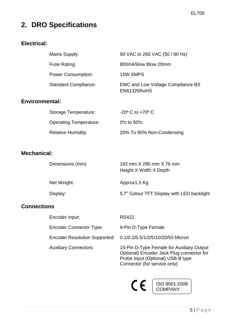
2. DRO Specifications
Electrical:
Mains Supply: 90 VAC to 265 VAC (50 / 60 Hz)
Fuse Rating: 800mASlow Blow 20mm
Power Consumption: 15W SMPS
Standard Compliance: EMC and Low Voltage Compliance BS
EN61326RoHS
Environmental:
Storage Temperature: -20º C to +70º C
Operating Temperature: 0ºc to 50ºc
Relative Humidity: 20% To 85% Non-Condensing
Mechanical:
Dimensions (mm) 192 mm X 290 mm X 76 mm
Height X Width X Depth
Net Weight: Approx1.5 Kg
Display: 5.7” Colour TFT Display with LED backlight
Connections
Encoder Input: RS422
Encoder Connector Type: 9-Pin D-Type Female
Encoder Resolution Supported: 0.1/0.2/0.5/1/2/5/10/20/50 Micron
Auxiliary Connectors: 15-Pin D-Type Female for Auxiliary Output Optional) Encoder Jack Plug connector for Probe input (Optional) USB B type Connector (for service only)
ISO 9001:2008 COMPANY
EL700
6 | P a g e
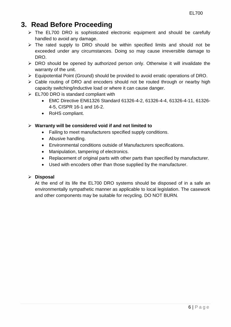
3. Read Before Proceeding The EL700 DRO is sophisticated electronic equipment and should be carefully
handled to avoid any damage.
The rated supply to DRO should be within specified limits and should not be
exceeded under any circumstances. Doing so may cause irreversible damage to
DRO.
DRO should be opened by authorized person only. Otherwise it will invalidate the
warranty of the unit.
Equipotential Point (Ground) should be provided to avoid erratic operations of DRO.
Cable routing of DRO and encoders should not be routed through or nearby high
capacity switching/inductive load or where it can cause danger.
EL700 DRO is standard compliant with
EMC Directive EN61326 Standard 61326-4-2, 61326-4-4, 61326-4-11, 61326-
4-5, CISPR 16-1 and 16-2.
RoHS compliant.
Warranty will be considered void if and not limited to
Failing to meet manufacturers specified supply conditions.
Abusive handling.
Environmental conditions outside of Manufacturers specifications.
Manipulation, tampering of electronics.
Replacement of original parts with other parts than specified by manufacturer.
Used with encoders other than those supplied by the manufacturer.
Disposal
At the end of its life the EL700 DRO systems should be disposed of in a safe an
environmentally sympathetic manner as applicable to local legislation. The casework
and other components may be suitable for recycling. DO NOT BURN.
EL700
7 | P a g e
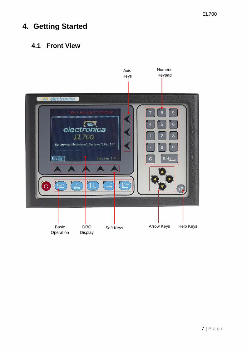
4. Getting Started
4.1 Front View
Basic
Operation
s
DRO
Display
Axis
Keys
Soft Keys
Numeric
Keypad
Arrow Keys Help Keys
EL700
8 | P a g e
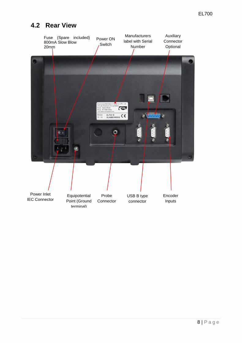
4.2 Rear View
Encoder
Inputs
Manufacturers
label with Serial
Number
Power Inlet
IEC Connector Equipotential
Point (Ground
terminal)
Power ON
Switch
Fuse (Spare included) 800mA Slow Blow 20mm
Probe
Connector
USB B type
connector
Auxiliary
Connector
Optional
EL700
9 | P a g e
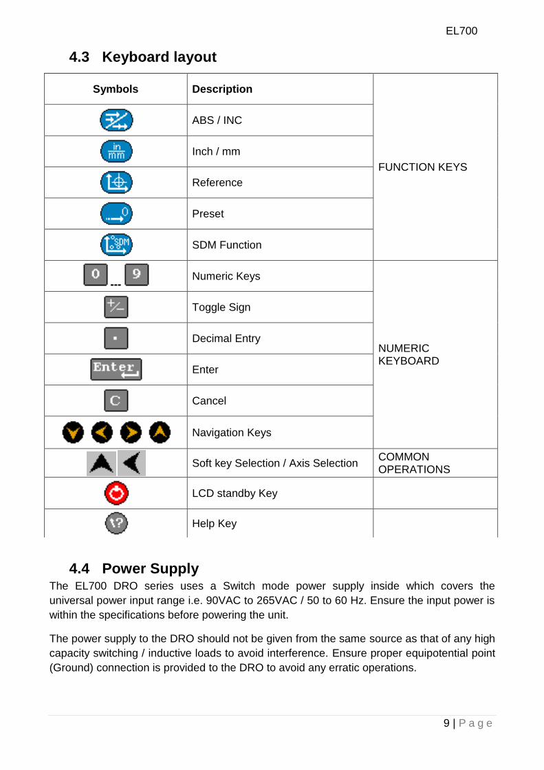
4.3 Keyboard layout
4.4 Power Supply The EL700 DRO series uses a Switch mode power supply inside which covers the
universal power input range i.e. 90VAC to 265VAC / 50 to 60 Hz. Ensure the input power is
within the specifications before powering the unit.
The power supply to the DRO should not be given from the same source as that of any high
capacity switching / inductive loads to avoid interference. Ensure proper equipotential point
(Ground) connection is provided to the DRO to avoid any erratic operations.
Symbols Description
FUNCTION KEYS
ABS / INC
Inch / mm
Reference
Preset
SDM Function
--- Numeric Keys
NUMERIC KEYBOARD
Toggle Sign
Decimal Entry
Enter
Cancel
Navigation Keys
Soft key Selection / Axis Selection
COMMON OPERATIONS
LCD standby Key
Help Key
EL700
10 | P a g e
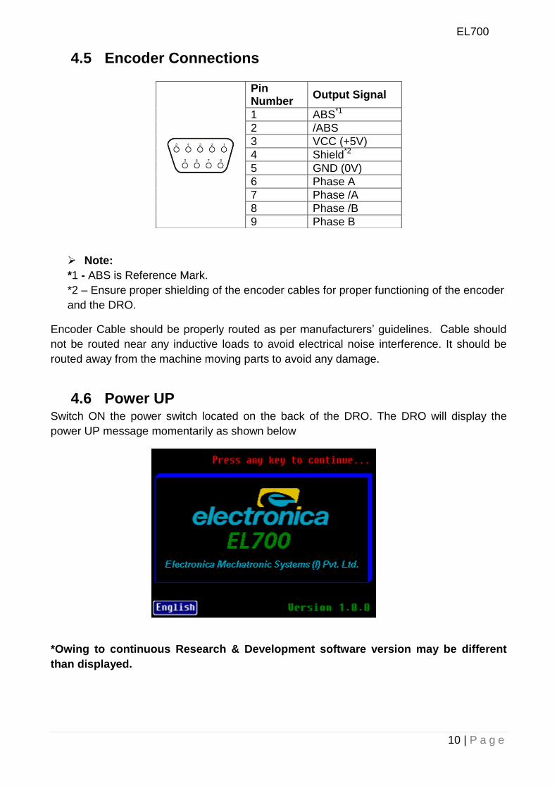
4.5 Encoder Connections
Note:
*1 - ABS is Reference Mark.
*2 – Ensure proper shielding of the encoder cables for proper functioning of the encoder
and the DRO.
Encoder Cable should be properly routed as per manufacturers‟ guidelines. Cable should
not be routed near any inductive loads to avoid electrical noise interference. It should be
routed away from the machine moving parts to avoid any damage.
4.6 Power UP Switch ON the power switch located on the back of the DRO. The DRO will display the
power UP message momentarily as shown below
*Owing to continuous Research & Development software version may be different
than displayed.
Pin Number
Output Signal
1 ABS*1
2 /ABS
3 VCC (+5V)
4 Shield*2
5 GND (0V)
6 Phase A
7 Phase /A
8 Phase /B
9 Phase B
EL700
11 | P a g e
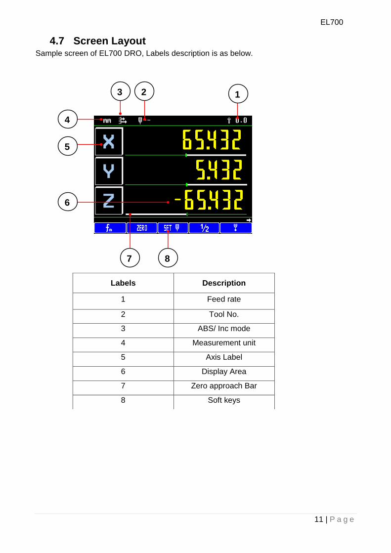
4.7 Screen Layout Sample screen of EL700 DRO, Labels description is as below.
Labels Description
1 Feed rate
2 Tool No.
3 ABS/ Inc mode
4 Measurement unit
5 Axis Label
6 Display Area
7 Zero approach Bar
8 Soft keys
1 2 3
4
5
6
7 8
EL700
12 | P a g e
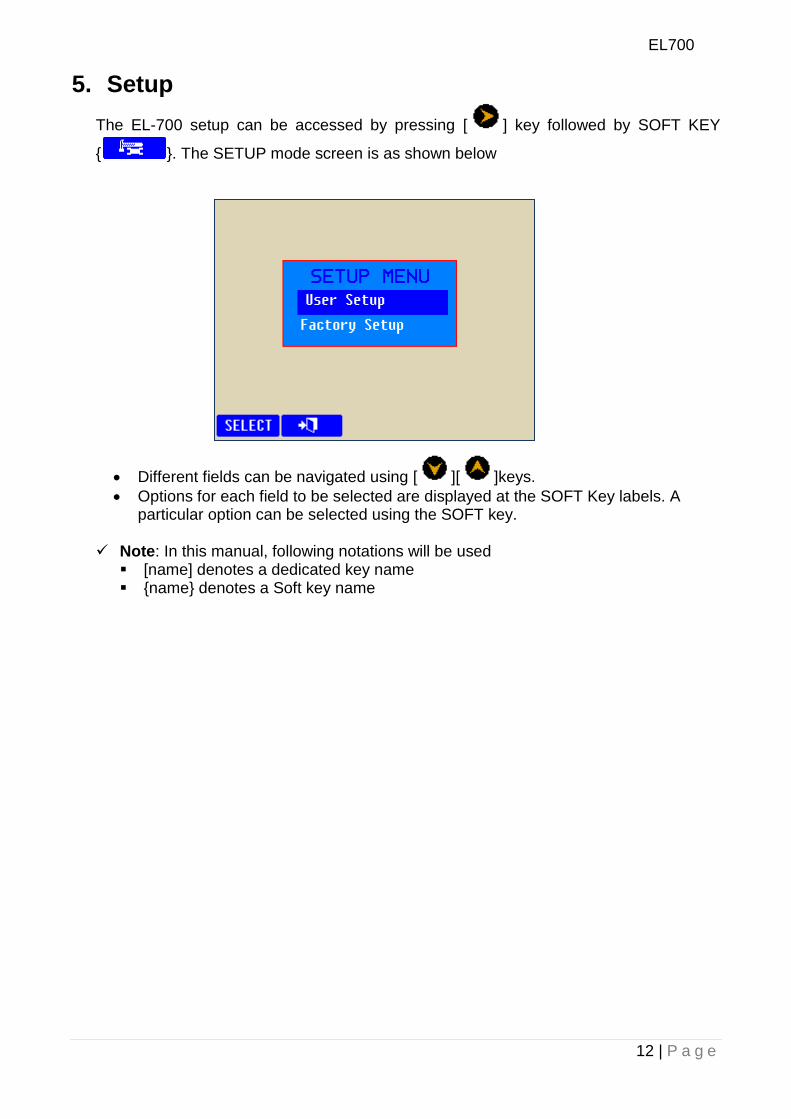
5. Setup
The EL-700 setup can be accessed by pressing [ ] key followed by SOFT KEY
{ }. The SETUP mode screen is as shown below
Different fields can be navigated using [ ][ ]keys.
Options for each field to be selected are displayed at the SOFT Key labels. A particular option can be selected using the SOFT key.
Note: In this manual, following notations will be used
[name] denotes a dedicated key name {name} denotes a Soft key name
EL700
13 | P a g e
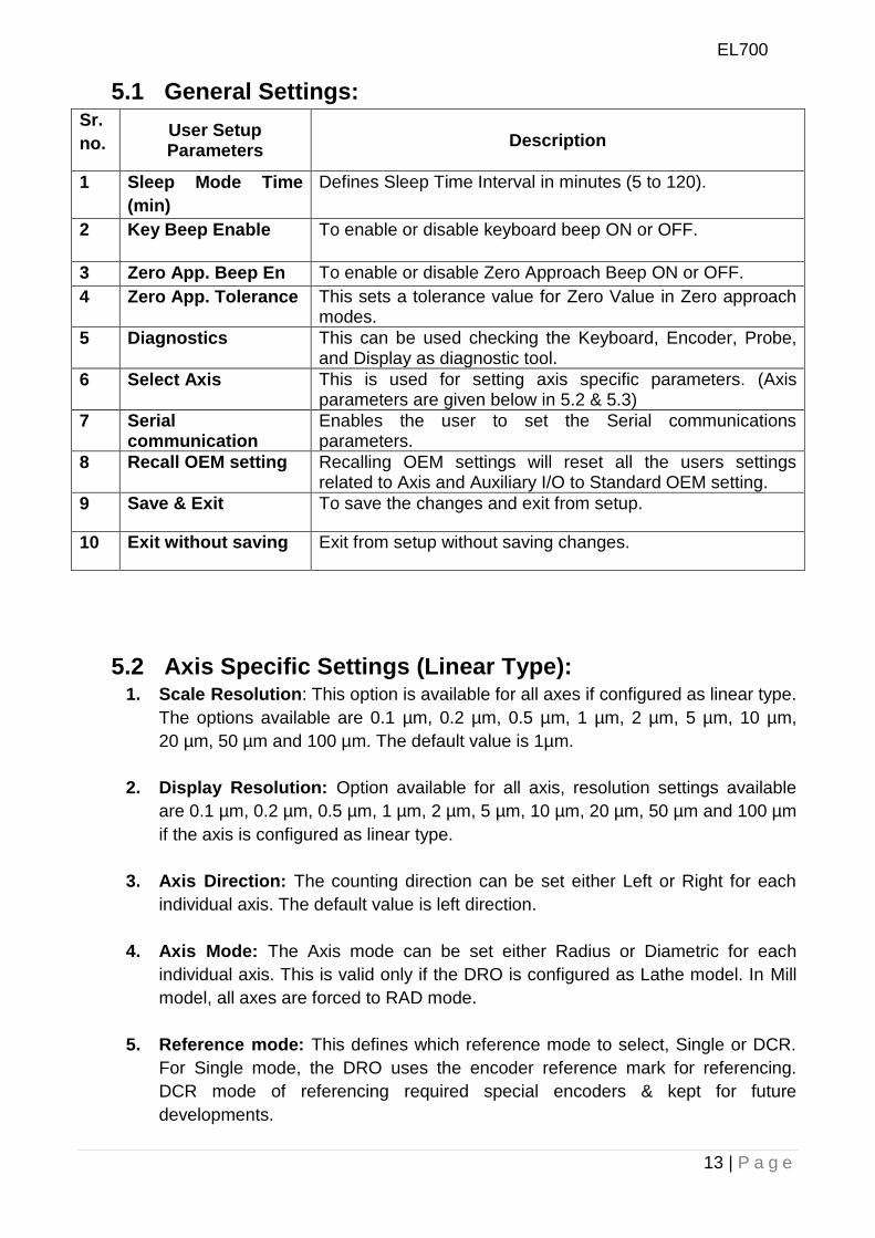
5.1 General Settings: Sr.
no. User Setup Parameters
Description
1 Sleep Mode Time
(min)
Defines Sleep Time Interval in minutes (5 to 120).
2 Key Beep Enable To enable or disable keyboard beep ON or OFF.
3 Zero App. Beep En To enable or disable Zero Approach Beep ON or OFF.
4 Zero App. Tolerance This sets a tolerance value for Zero Value in Zero approach modes.
5 Diagnostics This can be used checking the Keyboard, Encoder, Probe, and Display as diagnostic tool.
6 Select Axis This is used for setting axis specific parameters. (Axis parameters are given below in 5.2 & 5.3)
7 Serial communication
Enables the user to set the Serial communications parameters.
8 Recall OEM setting Recalling OEM settings will reset all the users settings related to Axis and Auxiliary I/O to Standard OEM setting.
9 Save & Exit To save the changes and exit from setup.
10 Exit without saving Exit from setup without saving changes.
5.2 Axis Specific Settings (Linear Type): 1. Scale Resolution: This option is available for all axes if configured as linear type.
The options available are 0.1 µm, 0.2 µm, 0.5 µm, 1 µm, 2 µm, 5 µm, 10 µm,
20 µm, 50 µm and 100 µm. The default value is 1µm.
2. Display Resolution: Option available for all axis, resolution settings available
are 0.1 µm, 0.2 µm, 0.5 µm, 1 µm, 2 µm, 5 µm, 10 µm, 20 µm, 50 µm and 100 µm
if the axis is configured as linear type.
3. Axis Direction: The counting direction can be set either Left or Right for each
individual axis. The default value is left direction.
4. Axis Mode: The Axis mode can be set either Radius or Diametric for each
individual axis. This is valid only if the DRO is configured as Lathe model. In Mill
model, all axes are forced to RAD mode.
5. Reference mode: This defines which reference mode to select, Single or DCR.
For Single mode, the DRO uses the encoder reference mark for referencing.
DCR mode of referencing required special encoders & kept for future
developments.
EL700
14 | P a g e
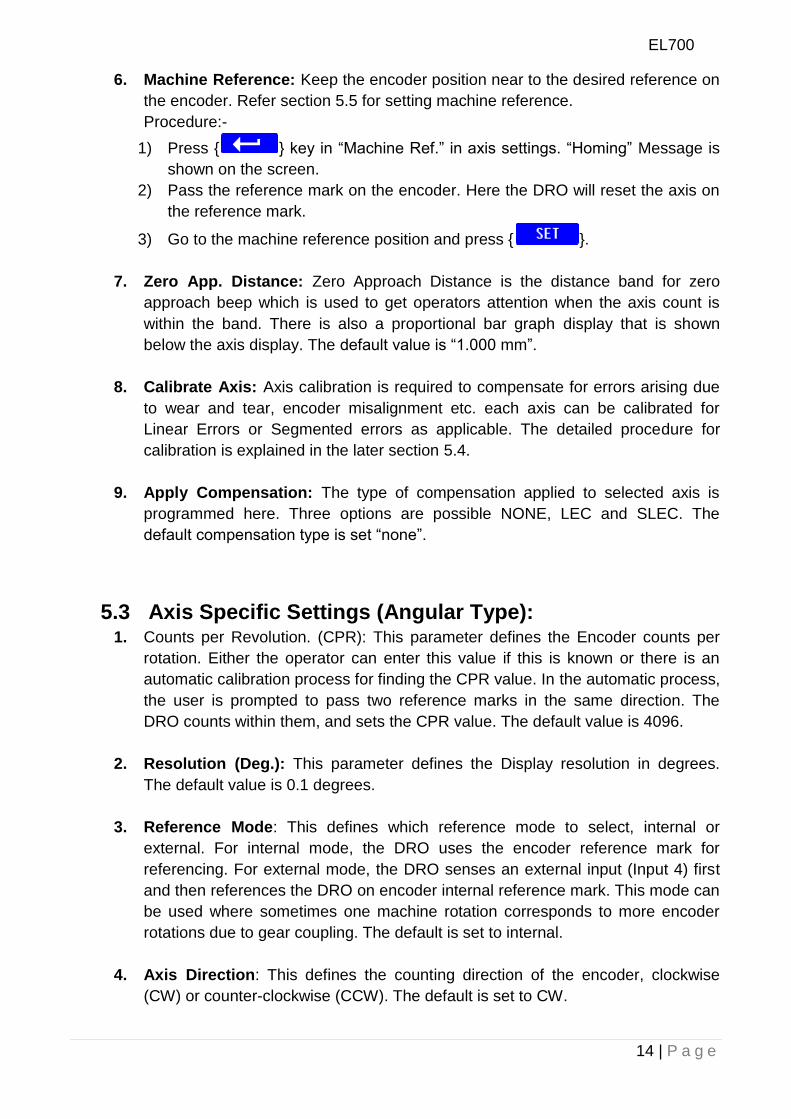
6. Machine Reference: Keep the encoder position near to the desired reference on
the encoder. Refer section 5.5 for setting machine reference.
Procedure:-
1) Press { } key in “Machine Ref.” in axis settings. “Homing” Message is
shown on the screen.
2) Pass the reference mark on the encoder. Here the DRO will reset the axis on
the reference mark.
3) Go to the machine reference position and press { }.
7. Zero App. Distance: Zero Approach Distance is the distance band for zero
approach beep which is used to get operators attention when the axis count is
within the band. There is also a proportional bar graph display that is shown
below the axis display. The default value is “1.000 mm”.
8. Calibrate Axis: Axis calibration is required to compensate for errors arising due
to wear and tear, encoder misalignment etc. each axis can be calibrated for
Linear Errors or Segmented errors as applicable. The detailed procedure for
calibration is explained in the later section 5.4.
9. Apply Compensation: The type of compensation applied to selected axis is
programmed here. Three options are possible NONE, LEC and SLEC. The
default compensation type is set “none”.
5.3 Axis Specific Settings (Angular Type): 1. Counts per Revolution. (CPR): This parameter defines the Encoder counts per
rotation. Either the operator can enter this value if this is known or there is an
automatic calibration process for finding the CPR value. In the automatic process,
the user is prompted to pass two reference marks in the same direction. The
DRO counts within them, and sets the CPR value. The default value is 4096.
2. Resolution (Deg.): This parameter defines the Display resolution in degrees.
The default value is 0.1 degrees.
3. Reference Mode: This defines which reference mode to select, internal or
external. For internal mode, the DRO uses the encoder reference mark for
referencing. For external mode, the DRO senses an external input (Input 4) first
and then references the DRO on encoder internal reference mark. This mode can
be used where sometimes one machine rotation corresponds to more encoder
rotations due to gear coupling. The default is set to internal.
4. Axis Direction: This defines the counting direction of the encoder, clockwise
(CW) or counter-clockwise (CCW). The default is set to CW.
EL700
15 | P a g e
5. Count Mode: Under this parameter there are two options:
Rollover: The angle rolls back to zero after 360.
Continuous: The angle continues accumulating after 360.
The default is set to Continuous mode.
6. Machine reference: There are two types of reference mode, as described In
section 5.3.3
a. Internal reference: -This is similar to that in linear. Only thing the value
is set in degrees.
b. External mode: - The DRO senses an external input first and then
references the DRO on encoder internal reference mark.
7. Display Mode: The angular axis is configurable for two possible options.
a. DDMMSS – Degrees: Minutes: Seconds (00.00.00).
b. DDDEC – Decimal Degrees (0.0000).
The default mode is DDMMSS.
8. Axis Lock: Two options are possible for this parameter.
a. Axis Lock ON
b. Axis Lock OFF.
Axis Lock ON prevents the operator from axis setting in absolute mode. Only the
operator can perform referencing. The default value is Axis Lock OFF.
9. Zero App. Angle: This is similar to the Zero Approach distance in linear mode.
Only the setting is in angular mode. The default value is 10.00.00.
10. Zero App. Tolerance: This is similar to the Zero approach tolerance in linear
mode. Only the setting is in angular mode. The default value is 0.00.00.
Note
The changes made in the setup mode should be saved by using “Save and Exit”.
Note that the options for each Menu item are displayed on the Soft key label.
User has to press the correct soft key for required settings.
EL700
16 | P a g e
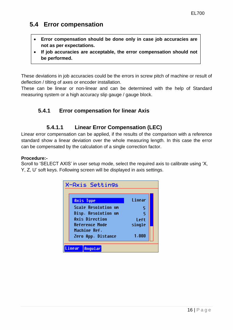
5.4 Error compensation
These deviations in job accuracies could be the errors in screw pitch of machine or result of
deflection / tilting of axes or encoder installation.
These can be linear or non-linear and can be determined with the help of Standard
measuring system or a high accuracy slip gauge / gauge block.
5.4.1 Error compensation for linear Axis
5.4.1.1 Linear Error Compensation (LEC)
Linear error compensation can be applied, if the results of the comparison with a reference
standard show a linear deviation over the whole measuring length. In this case the error
can be compensated by the calculation of a single correction factor.
Procedure:- Scroll to „SELECT AXIS‟ in user setup mode, select the required axis to calibrate using „X,
Y, Z, U‟ soft keys. Following screen will be displayed in axis settings.
Error compensation should be done only in case job accuracies are
not as per expectations.
If job accuracies are acceptable, the error compensation should not
be performed.
EL700
17 | P a g e
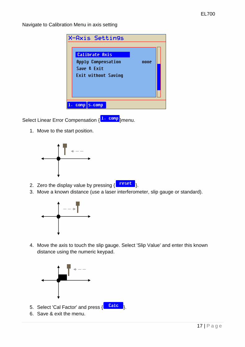
Navigate to Calibration Menu in axis setting
Select Linear Error Compensation { }menu.
1. Move to the start position.
2. Zero the display value by pressing { }.
3. Move a known distance (use a laser interferometer, slip gauge or standard).
4. Move the axis to touch the slip gauge. Select 'Slip Value' and enter this known
distance using the numeric keypad.
5. Select 'Cal Factor' and press { }.
6. Save & exit the menu.
EL700
18 | P a g e
Machine Reference
point
Home Reference
point
Travel
1 2 3 4 5 ERROR
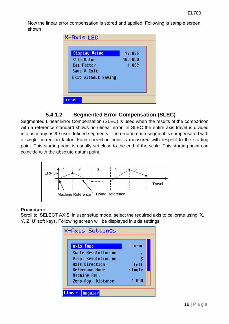
Now the linear error compensation is stored and applied. Following is sample screen
shown
5.4.1.2 Segmented Error Compensation (SLEC)
Segmented Linear Error Compensation (SLEC) is used when the results of the comparison
with a reference standard shows non-linear error. In SLEC the entire axis travel is divided
into as many as 99 user defined segments. The error in each segment is compensated with
a single correction factor. Each correction point is measured with respect to the starting
point. This starting point is usually set close to the end of the scale. This starting point can
coincide with the absolute datum point.
Procedure:- Scroll to „SELECT AXIS‟ in user setup mode, select the required axis to calibrate using „X,
Y, Z, U‟ soft keys. Following screen will be displayed in axis settings.
EL700
19 | P a g e
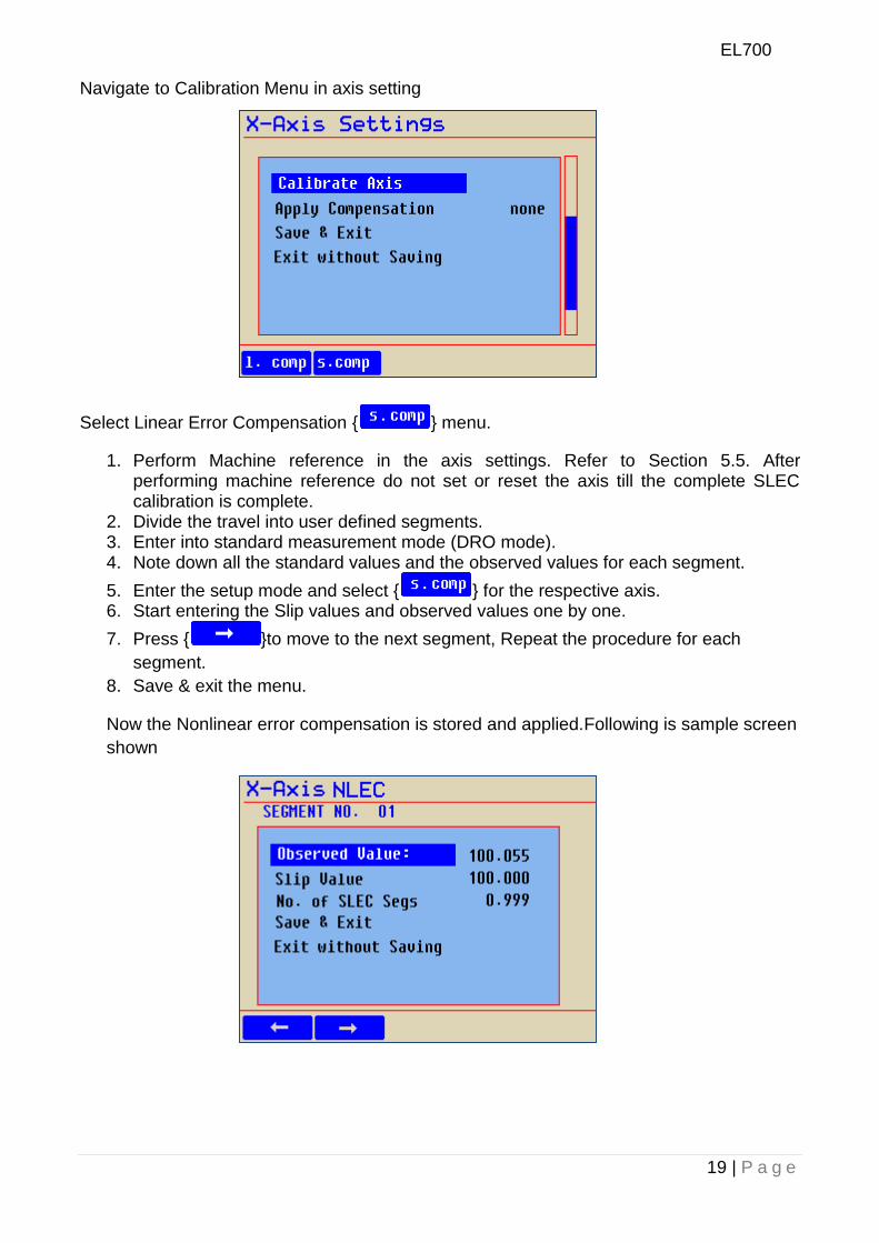
Navigate to Calibration Menu in axis setting
Select Linear Error Compensation { } menu.
1. Perform Machine reference in the axis settings. Refer to Section 5.5. After performing machine reference do not set or reset the axis till the complete SLEC calibration is complete.
2. Divide the travel into user defined segments. 3. Enter into standard measurement mode (DRO mode). 4. Note down all the standard values and the observed values for each segment.
5. Enter the setup mode and select { } for the respective axis. 6. Start entering the Slip values and observed values one by one.
7. Press { }to move to the next segment, Repeat the procedure for each
segment.
8. Save & exit the menu.
Now the Nonlinear error compensation is stored and applied.Following is sample screen
shown
EL700
20 | P a g e
5.5 Machine reference Machine referencing is used when datum is not at the reference mark on encoder but at a
fixed distance from reference mark.
Setting the machine reference
Scroll to „Select Axis‟ in user setup, select axis „X.Y, Z, U‟ from the soft keys. In axis setting
keys Select machine Ref. & follow the steps below.
1. Press { } when 'Machine Ref.' is highlighted.
The screen displays the message 'homing...‟ Move the slider to the reference point
on encoder.
Mark this reference position for future use.
2. Once the reference mark is sensed screen will display 'Set MC Ref.' Message.
3. Now travel to the desired position on the machine till machine reference point is
achieved.
4. Press the { } key.
The axis machine reference is now saved in DRO. To use this reference as your absolute
zero in operations, you will have to recall machine reference by pressing [ ] key.
This is very important when you use segmented axis compensation.
EL700
21 | P a g e
6. Primary functions
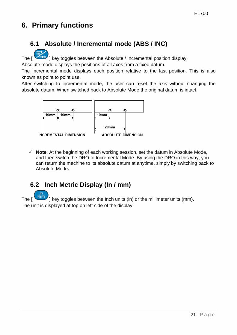
6.1 Absolute / Incremental mode (ABS / INC)
The [ ] key toggles between the Absolute / Incremental position display.
Absolute mode displays the positions of all axes from a fixed datum.
The Incremental mode displays each position relative to the last position. This is also
known as point to point use.
After switching to incremental mode, the user can reset the axis without changing the
absolute datum. When switched back to Absolute Mode the original datum is intact.
Note: At the beginning of each working session, set the datum in Absolute Mode,
and then switch the DRO to Incremental Mode. By using the DRO in this way, you can return the machine to its absolute datum at anytime, simply by switching back to Absolute Mode.
6.2 Inch Metric Display (In / mm)
The [ ] key toggles between the Inch units (in) or the millimeter units (mm).
The unit is displayed at top on left side of the display.
EL700
22 | P a g e
6.3 Axis Set/Reset This function is used to set the axis with a known value or to Zero the axis.
6.3.1 Axis Set: -
This function is used to set the axis with a known value.
Press { } key to switch DRO in set mode, Select the axis to set be pressing the
[ ]. Enter the numeric value to be set using numeric keypad and press[ ] to
confirm. Incorrect numeric entries can be cancelled one by one using [ ] key.
6.3.2 Axis Reset: -
This function is used to Zero the axis.
Press { } key to switch DRO in reset mode, Press the [ ] key to be reset.
When axis Set/Reset function is activated in ABS mode, it will redefine the datum of
the travel, and then it is not possible to restore the old datum.
6.4 Half Function This function is used to find the center of a work piece by halving the displayed distance on
the selected axis.
Press { } key followed by [ ]key will half the value of axis display.
It is recommended to use this function in INC mode. If you press this key in ABS
mode, it will change the datum point of the axis.
EL700
23 | P a g e
6.5 Probe Measurement
The probe function { } allows the operator to set an axis value or measure a work-
piece feature. There are different modes of operation for this.
The basic modes of operation are:
a. Datum Axis.
b. Linear Measurement mode
c. Angle Measurement mode
d. Diameter Measurement mode
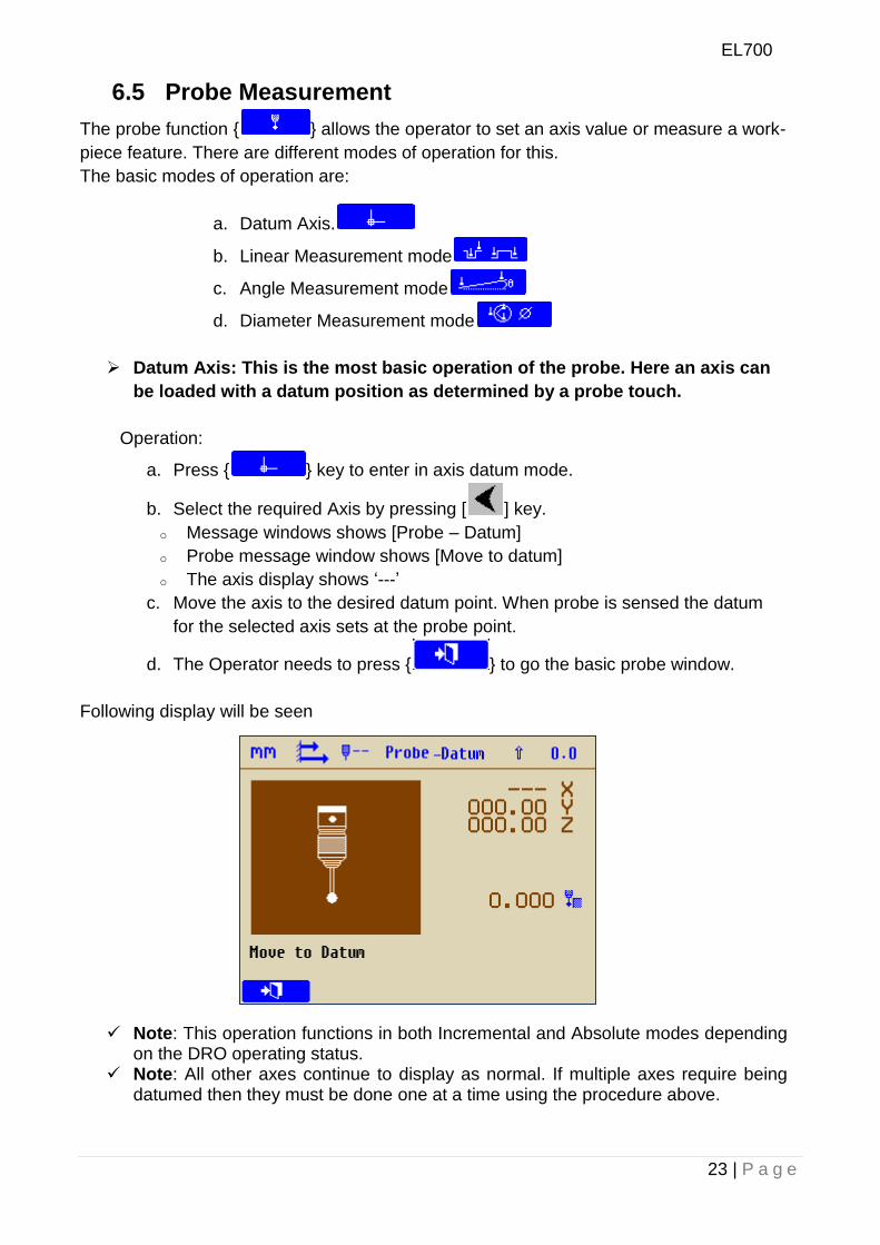
Datum Axis: This is the most basic operation of the probe. Here an axis can
be loaded with a datum position as determined by a probe touch.
Operation:
a. Press { } key to enter in axis datum mode.
b. Select the required Axis by pressing [ ] key.
o Message windows shows [Probe – Datum]
o Probe message window shows [Move to datum]
o The axis display shows „---‟
c. Move the axis to the desired datum point. When probe is sensed the datum
for the selected axis sets at the probe point.
d. The Operator needs to press { } to go the basic probe window.
Following display will be seen
Note: This operation functions in both Incremental and Absolute modes depending on the DRO operating status.
Note: All other axes continue to display as normal. If multiple axes require being datumed then they must be done one at a time using the procedure above.
EL700
24 | P a g e
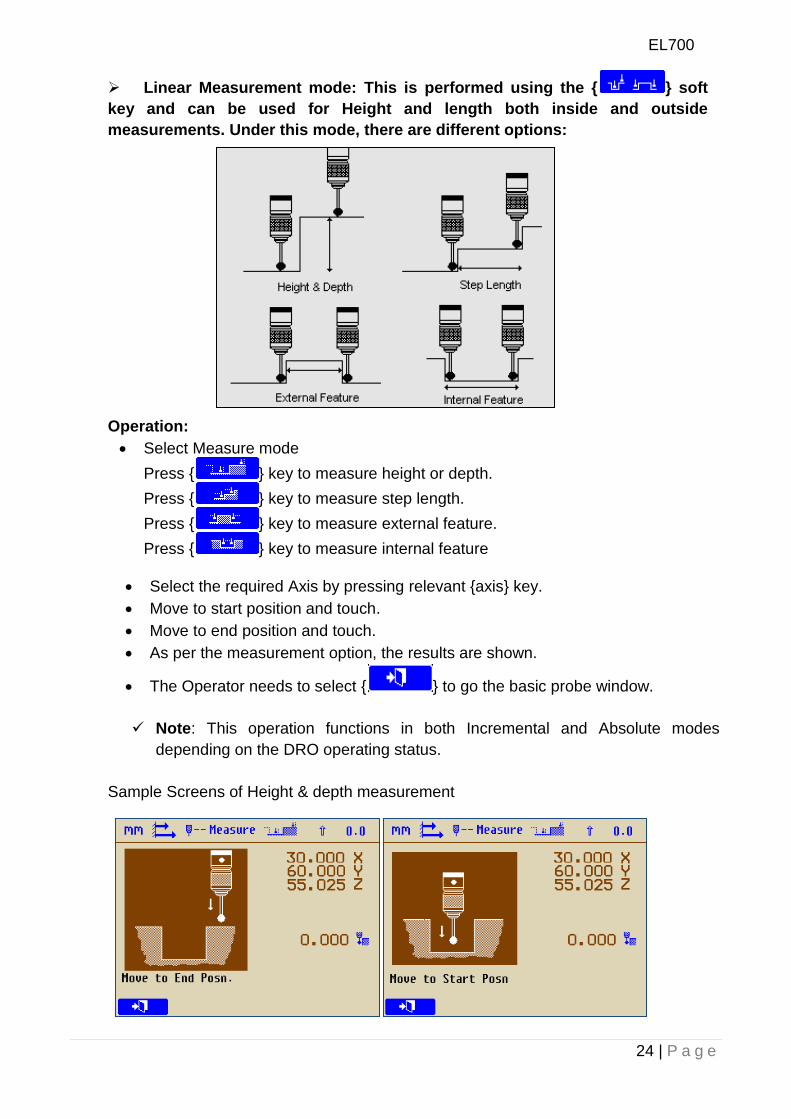
Linear Measurement mode: This is performed using the { } soft
key and can be used for Height and length both inside and outside
measurements. Under this mode, there are different options:
Operation:
Select Measure mode
Press { } key to measure height or depth.
Press { } key to measure step length.
Press { } key to measure external feature.
Press { } key to measure internal feature
Select the required Axis by pressing relevant {axis} key.
Move to start position and touch.
Move to end position and touch.
As per the measurement option, the results are shown.
The Operator needs to select { } to go the basic probe window.
Note: This operation functions in both Incremental and Absolute modes
depending on the DRO operating status.
Sample Screens of Height & depth measurement
EL700
25 | P a g e
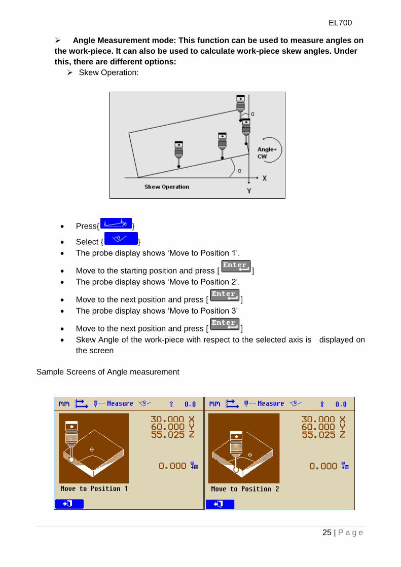
Angle Measurement mode: This function can be used to measure angles on
the work-piece. It can also be used to calculate work-piece skew angles. Under
this, there are different options:
Skew Operation:
Press{ }
Select { }
The probe display shows „Move to Position 1‟.
Move to the starting position and press [ ]
The probe display shows „Move to Position 2‟.
Move to the next position and press [ ]
The probe display shows „Move to Position 3‟
Move to the next position and press [ ]
Skew Angle of the work-piece with respect to the selected axis is displayed on
the screen
Sample Screens of Angle measurement
EL700
26 | P a g e
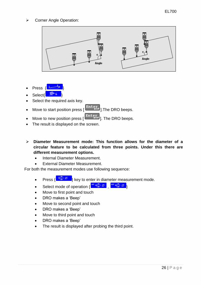
Corner Angle Operation:
Press { }
Select{ }
Select the required axis key.
Move to start position press [ ].The DRO beeps.
Move to new position press [ ]. The DRO beeps.
The result is displayed on the screen.
Diameter Measurement mode: This function allows for the diameter of a
circular feature to be calculated from three points. Under this there are
different measurement options.
Internal Diameter Measurement.
External Diameter Measurement.
For both the measurement modes use following sequence:
Press { } key to enter in diameter measurement mode.
Select mode of operation { , }
Move to first point and touch
DRO makes a „Beep‟
Move to second point and touch
DRO makes a „Beep‟
Move to third point and touch
DRO makes a „Beep‟
The result is displayed after probing the third point.
EL700
27 | P a g e
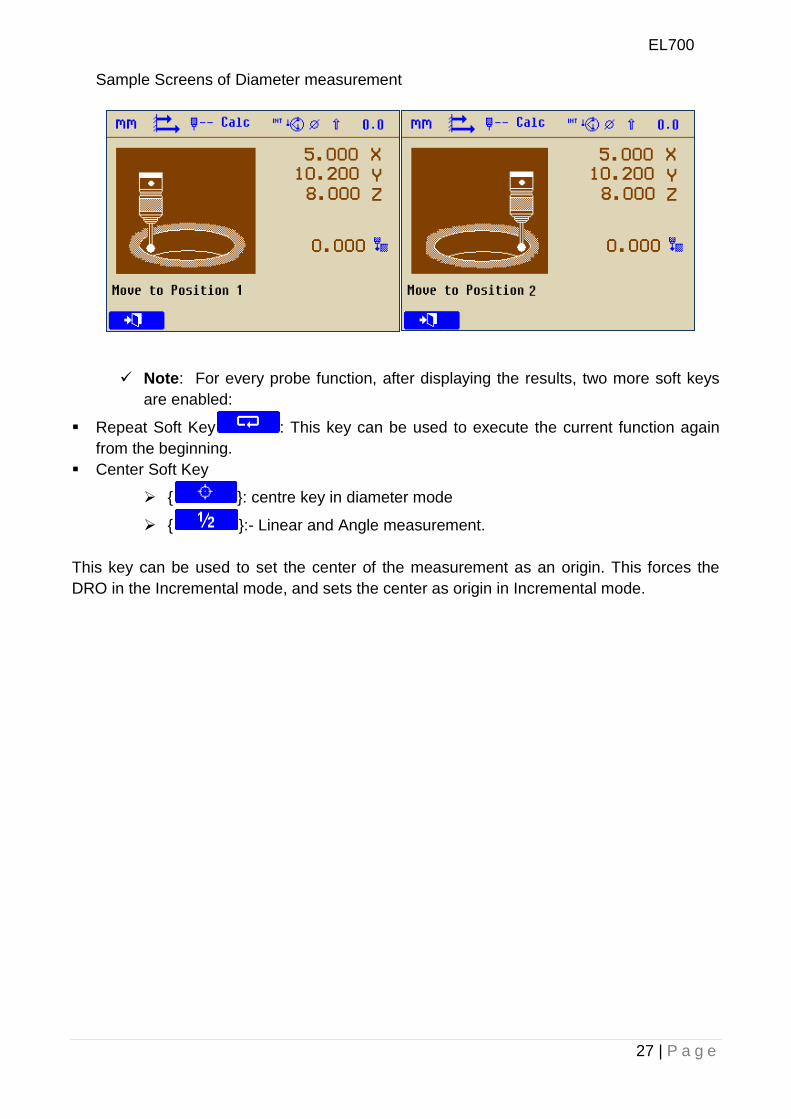
Sample Screens of Diameter measurement
Note: For every probe function, after displaying the results, two more soft keys
are enabled:
Repeat Soft Key : This key can be used to execute the current function again
from the beginning.
Center Soft Key
{ }: centre key in diameter mode
{ }:- Linear and Angle measurement.
This key can be used to set the center of the measurement as an origin. This forces the
DRO in the Incremental mode, and sets the center as origin in Incremental mode.
EL700
28 | P a g e
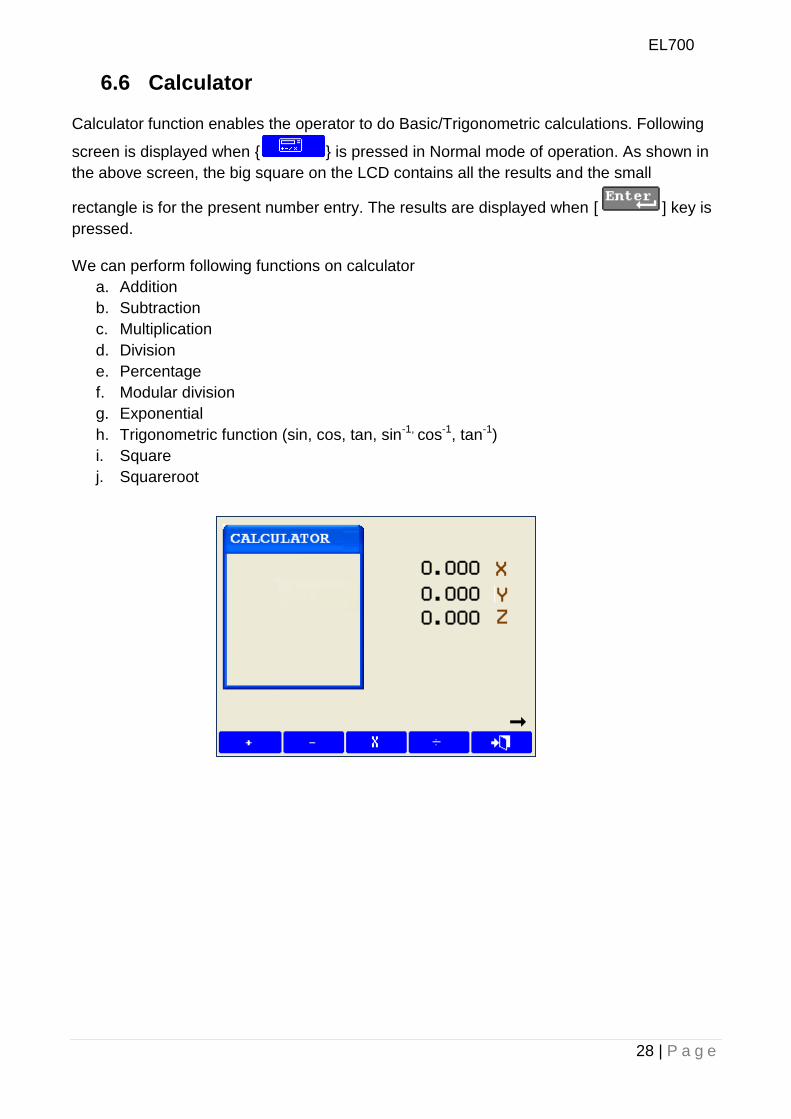
6.6 Calculator
Calculator function enables the operator to do Basic/Trigonometric calculations. Following
screen is displayed when { } is pressed in Normal mode of operation. As shown in
the above screen, the big square on the LCD contains all the results and the small
rectangle is for the present number entry. The results are displayed when [ ] key is
pressed.
We can perform following functions on calculator
a. Addition
b. Subtraction
c. Multiplication
d. Division
e. Percentage
f. Modular division
g. Exponential
h. Trigonometric function (sin, cos, tan, sin-1, cos-1, tan-1)
i. Square
j. Squareroot
EL700
29 | P a g e
6.7 Setting Reference This function allows user to set a machine zero point. With this machine zero point users
can restore the work coordinates even if the machine is moved when the DRO is in OFF
condition. Generally each encoder has reference marks present at every specified interval.
One of these reference marks is used to recall the same datum point every time.
This function works only in ABS mode. It will not be executed in INC mode.
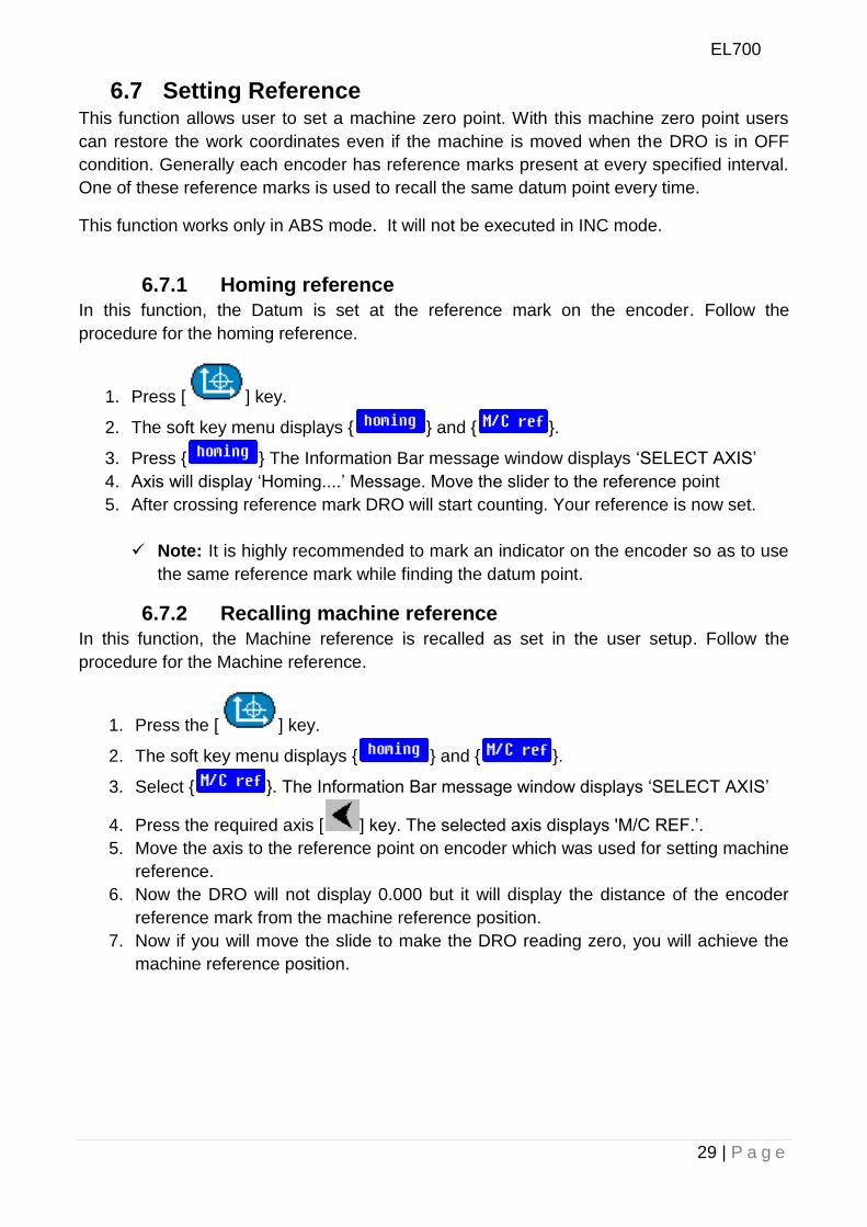
6.7.1 Homing reference
In this function, the Datum is set at the reference mark on the encoder. Follow the
procedure for the homing reference.
1. Press [ ] key.
2. The soft key menu displays { } and { }.
3. Press { } The Information Bar message window displays „SELECT AXIS‟
4. Axis will display „Homing....‟ Message. Move the slider to the reference point
5. After crossing reference mark DRO will start counting. Your reference is now set.
Note: It is highly recommended to mark an indicator on the encoder so as to use
the same reference mark while finding the datum point.
6.7.2 Recalling machine reference
In this function, the Machine reference is recalled as set in the user setup. Follow the
procedure for the Machine reference.
1. Press the [ ] key.
2. The soft key menu displays { } and { }.
3. Select { }. The Information Bar message window displays „SELECT AXIS‟
4. Press the required axis [ ] key. The selected axis displays 'M/C REF.‟.
5. Move the axis to the reference point on encoder which was used for setting machine
reference.
6. Now the DRO will not display 0.000 but it will display the distance of the encoder
reference mark from the machine reference position.
7. Now if you will move the slide to make the DRO reading zero, you will achieve the
machine reference position.
EL700
30 | P a g e
7. Secondary Functions
7.1 Preset The Preset function provides a simple mechanism for stepping through repeat positions
using the work-to-zero principle. It also takes into account positioning errors for repeated
points. The first time that you enter the function, the previous move error is set to zero. In
this way pressing only { } recalls any previous axis preset value.
Axis preset values are not maintained after a power cycle. The setting of the axis preset
value does take into account the error of any previous move. The value that you enter is the
step move value.
Pressing { } again recalls the axis preset value and takes into account the error of
any previous movement. Pressing { } after a power cycle results in a zero value.
The value of the axis Preset value that you enter is maintained until power-off. In this way
pressing after returning to the Preset function after exiting it previously, recalls the previous
axis-preset, without error adjustment as the error is set to zero on initial entry.
The values displayed do not affect the axis positions and the axis datum is restored when
you exit the Preset mode function.
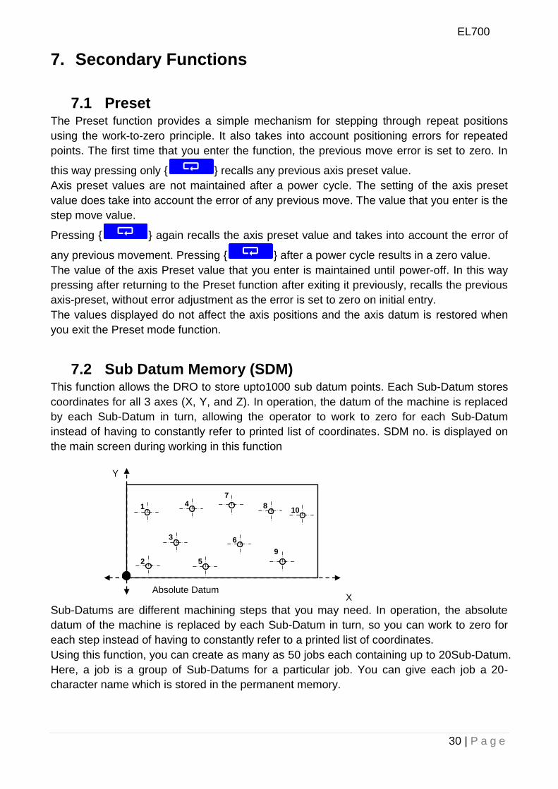
7.2 Sub Datum Memory (SDM) This function allows the DRO to store upto1000 sub datum points. Each Sub-Datum stores
coordinates for all 3 axes (X, Y, and Z). In operation, the datum of the machine is replaced
by each Sub-Datum in turn, allowing the operator to work to zero for each Sub-Datum
instead of having to constantly refer to printed list of coordinates. SDM no. is displayed on
the main screen during working in this function
Sub-Datums are different machining steps that you may need. In operation, the absolute
datum of the machine is replaced by each Sub-Datum in turn, so you can work to zero for
each step instead of having to constantly refer to a printed list of coordinates.
Using this function, you can create as many as 50 jobs each containing up to 20Sub-Datum.
Here, a job is a group of Sub-Datums for a particular job. You can give each job a 20-
character name which is stored in the permanent memory.
Absolute Datum X
Y
1
2
3
4
5
7
8
9
10
6
EL700
31 | P a g e
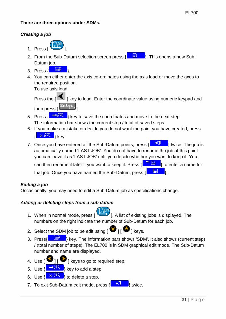
There are three options under SDMs.
Creating a job
1. Press [ ].
2. From the Sub-Datum selection screen press { }. This opens a new Sub-
Datum job.
3. Press { }.
4. You can either enter the axis co-ordinates using the axis load or move the axes to
the required position.
To use axis load:
Press the [ ] key to load. Enter the coordinate value using numeric keypad and
then press [ ].
5. Press { } key to save the coordinates and move to the next step.
The information bar shows the current step / total of saved steps.
6. If you make a mistake or decide you do not want the point you have created, press
{ } key.
7. Once you have entered all the Sub-Datum points, press { } twice. The job is
automatically named „LAST JOB‟. You do not have to rename the job at this point
you can leave it as „LAST JOB‟ until you decide whether you want to keep it. You
can then rename it later if you want to keep it. Press { } to enter a name for
that job. Once you have named the Sub-Datum, press { }.
Editing a job
Occasionally, you may need to edit a Sub-Datum job as specifications change.
Adding or deleting steps from a sub datum
1. When in normal mode, press [ ]. A list of existing jobs is displayed. The
numbers on the right indicate the number of Sub-Datum for each job.
2. Select the SDM job to be edit using [ ] [ ] keys.
3. Press{ } key. The information bars shows 'SDM'. It also shows (current step)
/ (total number of steps). The EL700 is in SDM graphical edit mode. The Sub-Datum
number and name are displayed.
4. Use [ ] [ ] keys to go to required step.
5. Use { } key to add a step.
6. Use { } to delete a step.
7. To exit Sub-Datum edit mode, press { } twice.
EL700
32 | P a g e
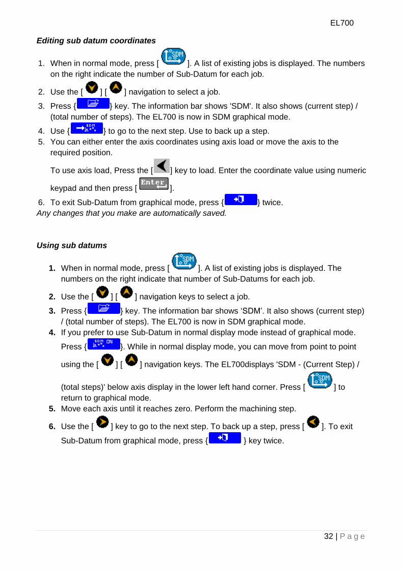
Editing sub datum coordinates
1. When in normal mode, press [ ]. A list of existing jobs is displayed. The numbers
on the right indicate the number of Sub-Datum for each job.
2. Use the [ ] [ ] navigation to select a job.
3. Press { } key. The information bar shows 'SDM'. It also shows (current step) /
(total number of steps). The EL700 is now in SDM graphical mode.
4. Use { } to go to the next step. Use to back up a step.
5. You can either enter the axis coordinates using axis load or move the axis to the
required position.
To use axis load, Press the [ ] key to load. Enter the coordinate value using numeric
keypad and then press [ ].
6. To exit Sub-Datum from graphical mode, press { } twice.
Any changes that you make are automatically saved.
Using sub datums
1. When in normal mode, press [ ]. A list of existing jobs is displayed. The
numbers on the right indicate that number of Sub-Datums for each job.
2. Use the [ ] [ ] navigation keys to select a job.
3. Press { } key. The information bar shows „SDM‟. It also shows (current step)
/ (total number of steps). The EL700 is now in SDM graphical mode.
4. If you prefer to use Sub-Datum in normal display mode instead of graphical mode.
Press { }. While in normal display mode, you can move from point to point
using the [ ] [ ] navigation keys. The EL700displays 'SDM - (Current Step) /
(total steps)' below axis display in the lower left hand corner. Press [ ] to
return to graphical mode.
5. Move each axis until it reaches zero. Perform the machining step.
6. Use the [ ] key to go to the next step. To back up a step, press [ ]. To exit
Sub-Datum from graphical mode, press { } key twice.
EL700
33 | P a g e
8. Machine Specific Functions
8.1 Milling Machine Specific Functions:-
If the DRO is of Mill type, following functions are available on { } key:
Bolt Hole (Circular and Arc)
Line Hole
Grid
Frame
Arc Contouring
R-Function
Slot
Polar Coordinates
Axis Summing
Zero approach
Job timer
Shrinkage factor
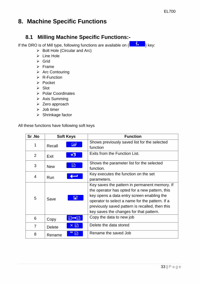
All these functions have following soft keys
Sr .No Soft Keys Function
1 Recall Shows previously saved list for the selected
function
2 Exit Exits from the Function List.
3 New Shows the parameter list for the selected
function.
4 Run Key executes the function on the set
parameters.
5 Save
Key saves the pattern in permanent memory. If
the operator has opted for a new pattern, this
key opens a data entry screen enabling the
operator to select a name for the pattern. If a
previously saved pattern is recalled, then this
key saves the changes for that pattern.
6 Copy Copy the data to new job
7 Delete Delete the data stored
8 Rename Rename the saved Job
EL700
34 | P a g e
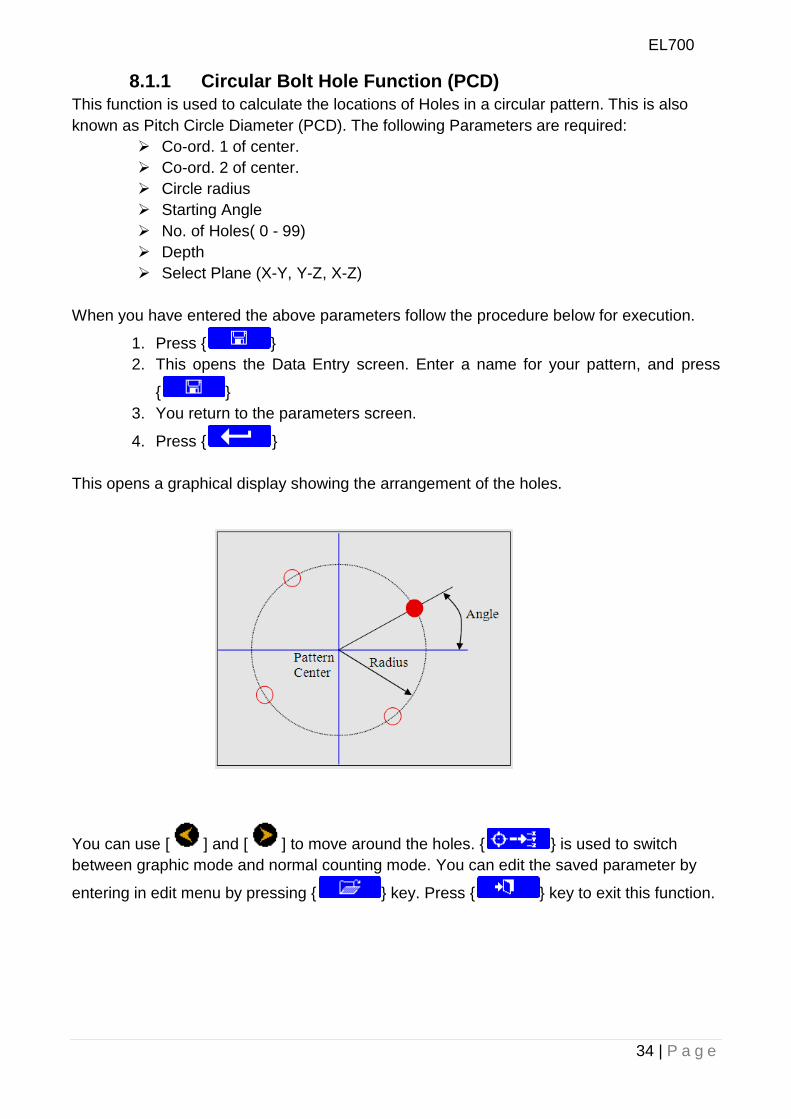
8.1.1 Circular Bolt Hole Function (PCD)
This function is used to calculate the locations of Holes in a circular pattern. This is also
known as Pitch Circle Diameter (PCD). The following Parameters are required:
Co-ord. 1 of center.
Co-ord. 2 of center.
Circle radius
Starting Angle
No. of Holes( 0 - 99)
Depth
Select Plane (X-Y, Y-Z, X-Z)
When you have entered the above parameters follow the procedure below for execution.
1. Press { }
2. This opens the Data Entry screen. Enter a name for your pattern, and press
{ }
3. You return to the parameters screen.
4. Press { }
This opens a graphical display showing the arrangement of the holes.
You can use [ ] and [ ] to move around the holes. { } is used to switch
between graphic mode and normal counting mode. You can edit the saved parameter by
entering in edit menu by pressing { } key. Press { } key to exit this function.
EL700
35 | P a g e
Radius
End Point
Start Point
Arc Center
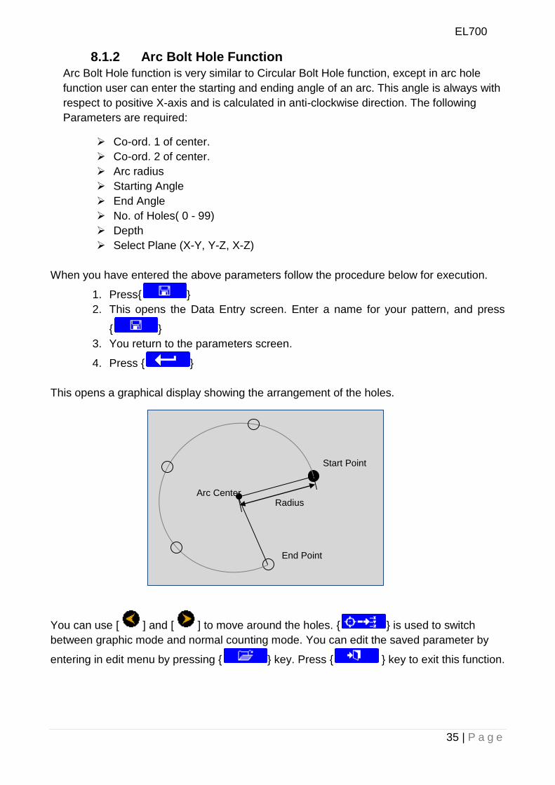
8.1.2 Arc Bolt Hole Function
Arc Bolt Hole function is very similar to Circular Bolt Hole function, except in arc hole
function user can enter the starting and ending angle of an arc. This angle is always with
respect to positive X-axis and is calculated in anti-clockwise direction. The following
Parameters are required:
Co-ord. 1 of center.
Co-ord. 2 of center.
Arc radius
Starting Angle
End Angle
No. of Holes( 0 - 99)
Depth
Select Plane (X-Y, Y-Z, X-Z)
When you have entered the above parameters follow the procedure below for execution.
1. Press{ }
2. This opens the Data Entry screen. Enter a name for your pattern, and press
{ }
3. You return to the parameters screen.
4. Press { }
This opens a graphical display showing the arrangement of the holes.
You can use [ ] and [ ] to move around the holes. { } is used to switch
between graphic mode and normal counting mode. You can edit the saved parameter by
entering in edit menu by pressing { } key. Press { } key to exit this function.
EL700
36 | P a g e
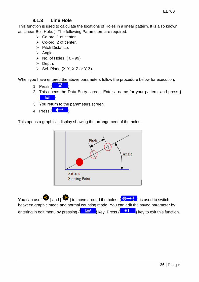
8.1.3 Line Hole
This function is used to calculate the locations of Holes in a linear pattern. It is also known
as Linear Bolt Hole. ). The following Parameters are required:
Co-ord. 1 of center.
Co-ord. 2 of center.
Pitch Distance.
Angle.
No. of Holes. ( 0 - 99)
Depth.
Sel. Plane (X-Y, X-Z or Y-Z).
When you have entered the above parameters follow the procedure below for execution.
1. Press { }
2. This opens the Data Entry screen. Enter a name for your pattern, and press {
}
3. You return to the parameters screen.
4. Press { }
This opens a graphical display showing the arrangement of the holes.
You can use[ ] and [ ] to move around the holes. { } is used to switch
between graphic mode and normal counting mode. You can edit the saved parameter by
entering in edit menu by pressing { } key. Press { } key to exit this function.
EL700
37 | P a g e
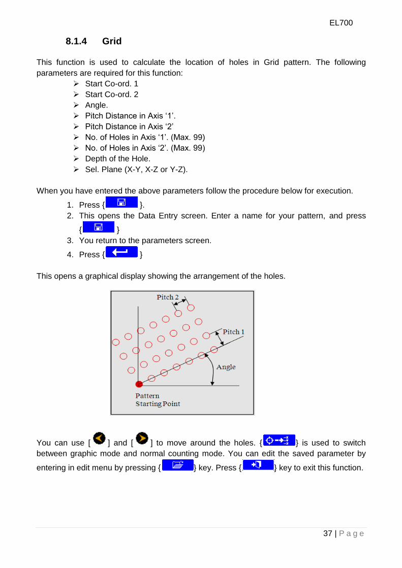
8.1.4 Grid
This function is used to calculate the location of holes in Grid pattern. The following
parameters are required for this function:
Start Co-ord. 1
Start Co-ord. 2
Angle.
Pitch Distance in Axis „1‟.
Pitch Distance in Axis „2‟
No. of Holes in Axis „1‟. (Max. 99)
No. of Holes in Axis „2‟. (Max. 99)
Depth of the Hole.
Sel. Plane (X-Y, X-Z or Y-Z).
When you have entered the above parameters follow the procedure below for execution.
1. Press { }.
2. This opens the Data Entry screen. Enter a name for your pattern, and press
{ }
3. You return to the parameters screen.
4. Press { }
This opens a graphical display showing the arrangement of the holes.
You can use [ ] and [ ] to move around the holes. { } is used to switch
between graphic mode and normal counting mode. You can edit the saved parameter by
entering in edit menu by pressing { } key. Press { } key to exit this function.
EL700
38 | P a g e
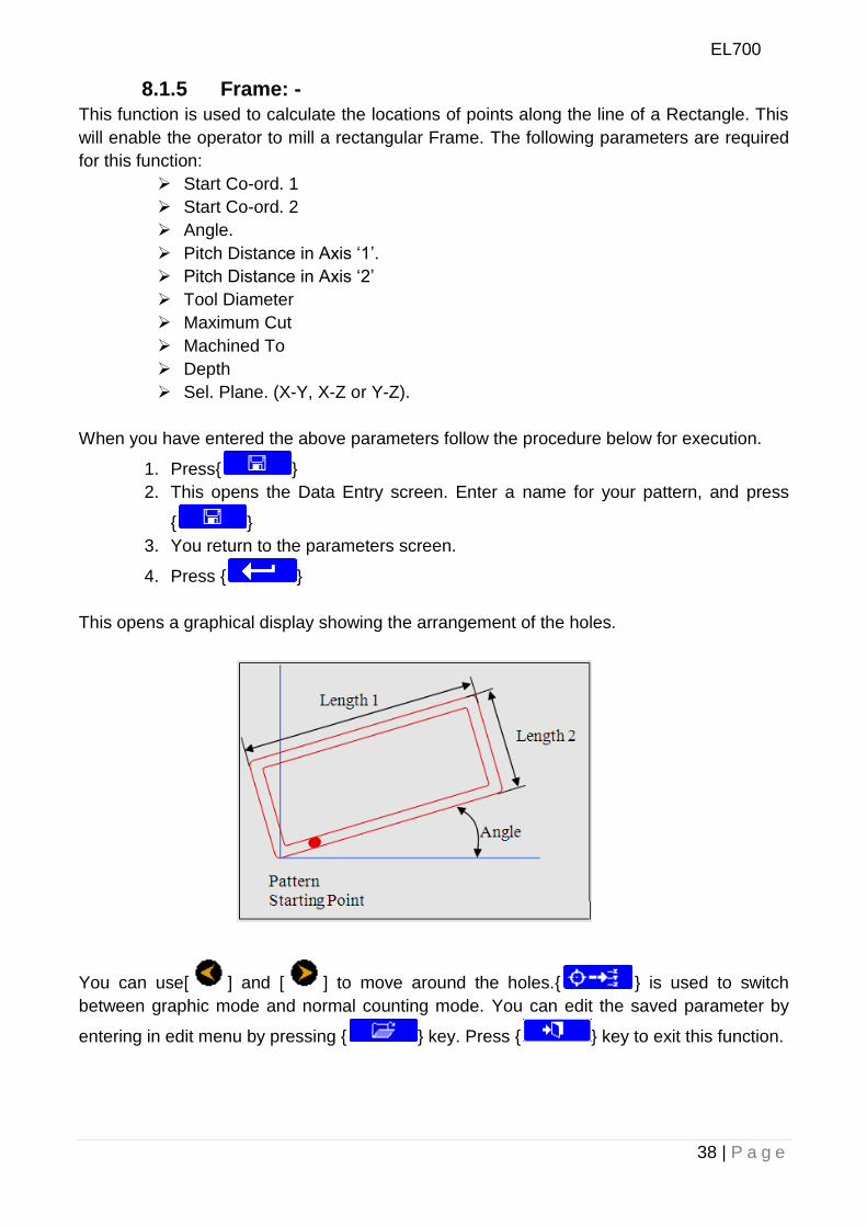
8.1.5 Frame: -
This function is used to calculate the locations of points along the line of a Rectangle. This
will enable the operator to mill a rectangular Frame. The following parameters are required
for this function:
Start Co-ord. 1
Start Co-ord. 2
Angle.
Pitch Distance in Axis „1‟.
Pitch Distance in Axis „2‟
Tool Diameter
Maximum Cut
Machined To
Depth
Sel. Plane. (X-Y, X-Z or Y-Z).
When you have entered the above parameters follow the procedure below for execution.
1. Press{ }
2. This opens the Data Entry screen. Enter a name for your pattern, and press
{ }
3. You return to the parameters screen.
4. Press { }
This opens a graphical display showing the arrangement of the holes.
You can use[ ] and [ ] to move around the holes.{ } is used to switch
between graphic mode and normal counting mode. You can edit the saved parameter by
entering in edit menu by pressing { } key. Press { } key to exit this function.
EL700
39 | P a g e
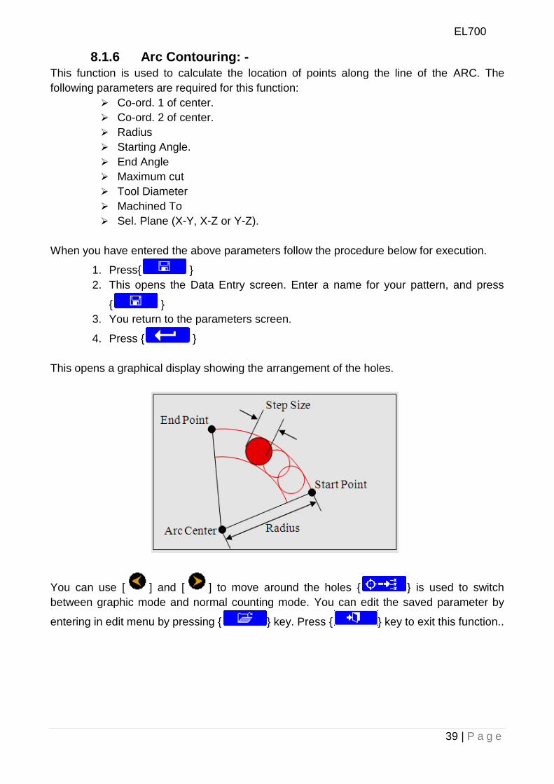
8.1.6 Arc Contouring: -
This function is used to calculate the location of points along the line of the ARC. The
following parameters are required for this function:
Co-ord. 1 of center.
Co-ord. 2 of center.
Radius
Starting Angle.
End Angle
Maximum cut
Tool Diameter
Machined To
Sel. Plane (X-Y, X-Z or Y-Z).
When you have entered the above parameters follow the procedure below for execution.
1. Press{ }
2. This opens the Data Entry screen. Enter a name for your pattern, and press
{ }
3. You return to the parameters screen.
4. Press { }
This opens a graphical display showing the arrangement of the holes.
You can use [ ] and [ ] to move around the holes { } is used to switch
between graphic mode and normal counting mode. You can edit the saved parameter by
entering in edit menu by pressing { } key. Press { } key to exit this function..
EL700
40 | P a g e
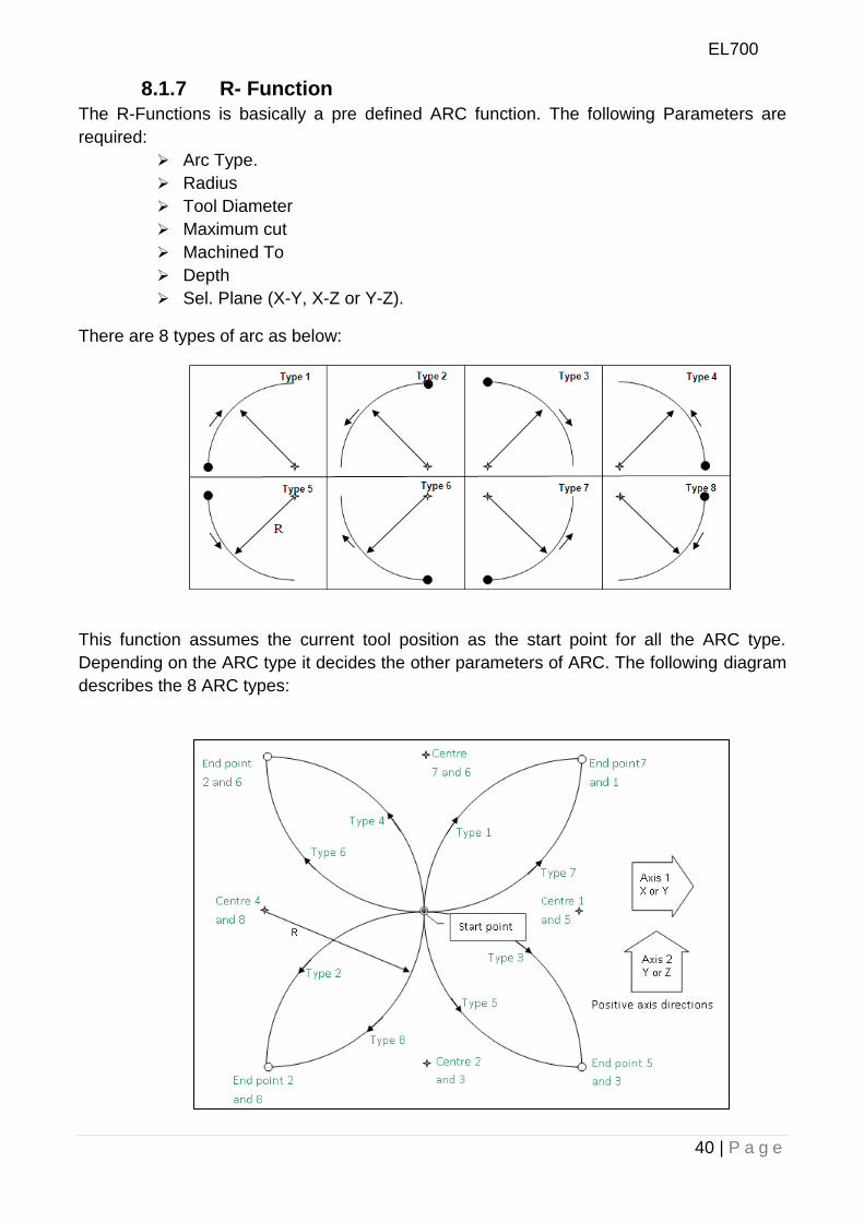
8.1.7 R- Function
The R-Functions is basically a pre defined ARC function. The following Parameters are
required:
Arc Type.
Radius
Tool Diameter
Maximum cut
Machined To
Depth
Sel. Plane (X-Y, X-Z or Y-Z).
There are 8 types of arc as below:
This function assumes the current tool position as the start point for all the ARC type.
Depending on the ARC type it decides the other parameters of ARC. The following diagram
describes the 8 ARC types:
EL700
41 | P a g e
When you have entered the above parameters follow the procedure below for execution.
1. Press { }
2. This opens the Data Entry screen. Enter a name for your pattern, and press
{ }
3. You return to the parameters screen.
4. Press { }
You can use [ ] and [ ] to move around the holes. { } is used to switch
between graphic mode and normal counting mode. You can edit the saved parameter by
entering in edit menu by pressing { } key. Press { } key to exit this function.
EL700
42 | P a g e
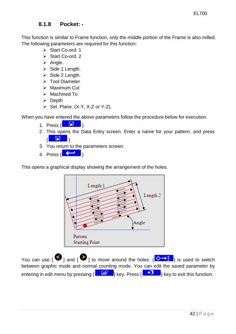
8.1.8 Pocket: -
This function is similar to Frame function, only the middle portion of the Frame is also milled.
The following parameters are required for this function:
Start Co-ord. 1
Start Co-ord. 2
Angle.
Side 1 Length.
Side 2 Length.
Tool Diameter
Maximum Cut
Machined To
Depth
Sel. Plane. (X-Y, X-Z or Y-Z).
When you have entered the above parameters follow the procedure below for execution.
1. Press { }
2. This opens the Data Entry screen. Enter a name for your pattern, and press
{ }
3. You return to the parameters screen.
4. Press { }
This opens a graphical display showing the arrangement of the holes.
You can use [ ] and [ ] to move around the holes. { } is used to switch
between graphic mode and normal counting mode. You can edit the saved parameter by
entering in edit menu by pressing { } key. Press { } key to exit this function.
EL700
43 | P a g e
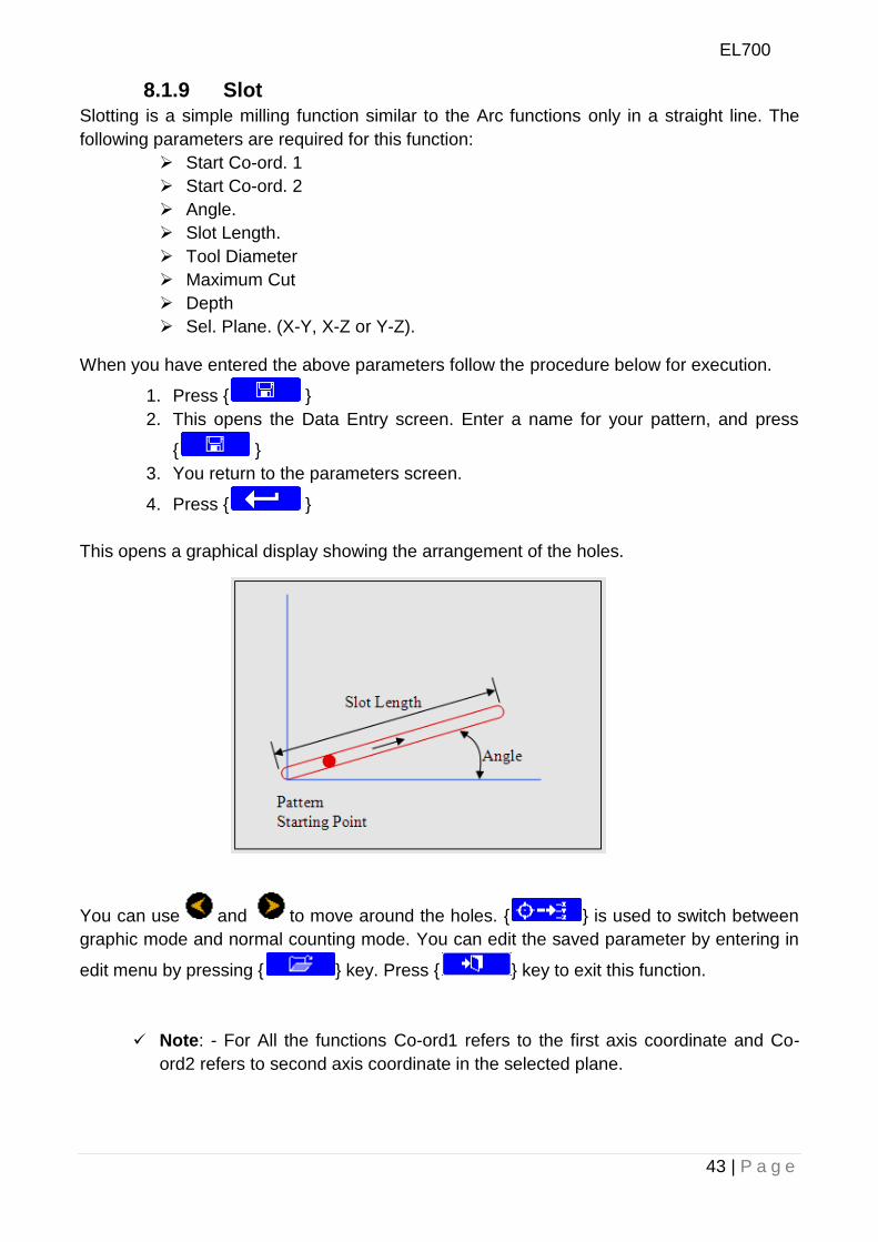
8.1.9 Slot
Slotting is a simple milling function similar to the Arc functions only in a straight line. The
following parameters are required for this function:
Start Co-ord. 1
Start Co-ord. 2
Angle.
Slot Length.
Tool Diameter
Maximum Cut
Depth
Sel. Plane. (X-Y, X-Z or Y-Z).
When you have entered the above parameters follow the procedure below for execution.
1. Press { }
2. This opens the Data Entry screen. Enter a name for your pattern, and press
{ }
3. You return to the parameters screen.
4. Press { }
This opens a graphical display showing the arrangement of the holes.
You can use and to move around the holes. { } is used to switch between
graphic mode and normal counting mode. You can edit the saved parameter by entering in
edit menu by pressing { } key. Press { } key to exit this function.
Note: - For All the functions Co-ord1 refers to the first axis coordinate and Co-
ord2 refers to second axis coordinate in the selected plane.
EL700
44 | P a g e
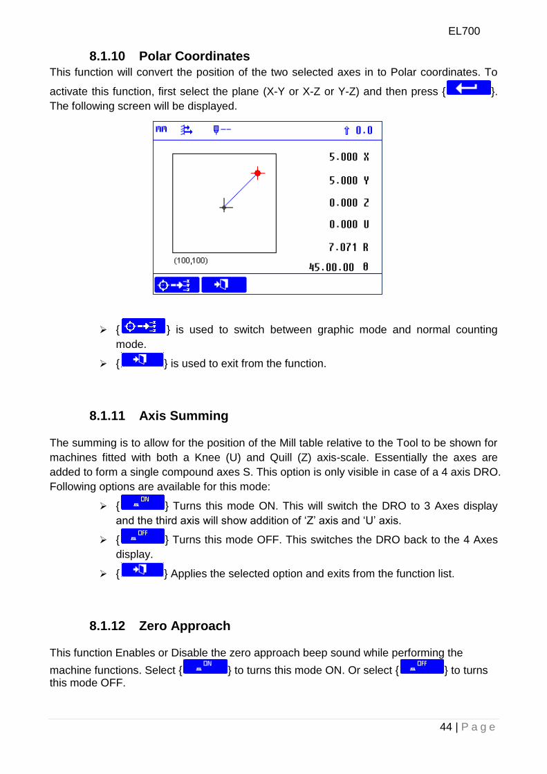
8.1.10 Polar Coordinates
This function will convert the position of the two selected axes in to Polar coordinates. To
activate this function, first select the plane (X-Y or X-Z or Y-Z) and then press { }.
The following screen will be displayed.
{ } is used to switch between graphic mode and normal counting
mode.
{ } is used to exit from the function.
8.1.11 Axis Summing
The summing is to allow for the position of the Mill table relative to the Tool to be shown for
machines fitted with both a Knee (U) and Quill (Z) axis-scale. Essentially the axes are
added to form a single compound axes S. This option is only visible in case of a 4 axis DRO.
Following options are available for this mode:
{ } Turns this mode ON. This will switch the DRO to 3 Axes display
and the third axis will show addition of „Z‟ axis and „U‟ axis.
{ } Turns this mode OFF. This switches the DRO back to the 4 Axes
display.
{ } Applies the selected option and exits from the function list.
8.1.12 Zero Approach
This function Enables or Disable the zero approach beep sound while performing the
machine functions. Select { } to turns this mode ON. Or select { } to turns this mode OFF.
EL700
45 | P a g e
8.1.13 Job Timer
This is a Timer utility and can be used by the operator to get the Time / Rate for completing
a particular Job. This has following Soft Keys:
{ } Starts the Job Timer.
{ } Stops the Job Timer.
{ } Resets the Job Timer.
{ } Exits from the function list.
{ } This enables the operator to enter the machining rate in units per
hour for the machine on which the DRO is operating. If this is set to zero, the
main DRO screen shows the Job Timer; otherwise it shows the machining
cost which is denoted by “#”.
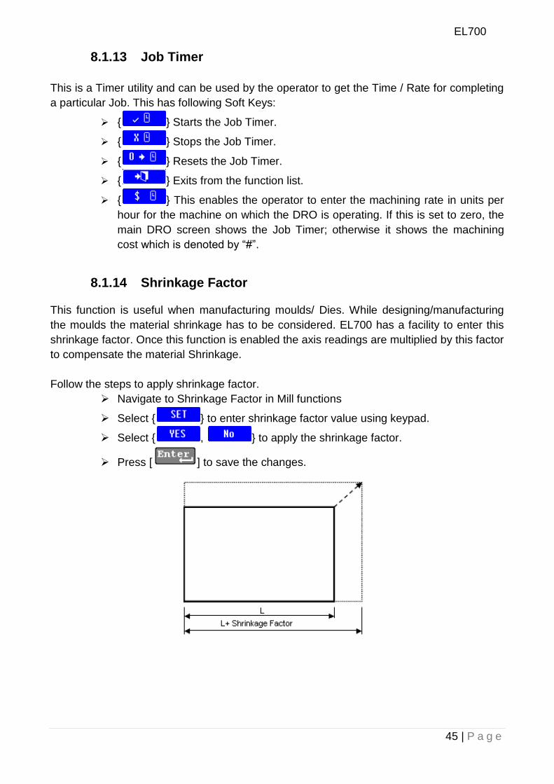
8.1.14 Shrinkage Factor
This function is useful when manufacturing moulds/ Dies. While designing/manufacturing
the moulds the material shrinkage has to be considered. EL700 has a facility to enter this
shrinkage factor. Once this function is enabled the axis readings are multiplied by this factor
to compensate the material Shrinkage.
Follow the steps to apply shrinkage factor.
Navigate to Shrinkage Factor in Mill functions
Select { } to enter shrinkage factor value using keypad.
Select { , } to apply the shrinkage factor.
Press [ ] to save the changes.
EL700
46 | P a g e
8.1.15 Tools
Mill mode
In Mill mode, you use this function to program the different tool parameters, such as
Diameter, Length, RPM (max) and Speed (max).These parameters can then be referred to
in different machining functions, such as Arc contouring and Grid.
When you press { }, the DRO shows the list of previously saved tools. It has the
following soft keys:
{ } creates a new tool setup. Maximum 99 new tools can be created.
The Data Entry screen is displayed so you can enter a tool name. A maximum
of 20 characters is allowed for a tool name.
{ } Applies the selected tool. The information stored under that tool
can then be used by the other functions. When you apply a specific tool, its
tool number is displayed on the main screen, for example T01.This number
also appears next to the tool name.
{ } Exits from the tool list to the main screen.
{ } Deletes the selected tool from the list. You are prompted to confirm
this before the tool is deleted.
{ } Edits the tool parameters under the selected tool.
{ } Renames the tool.
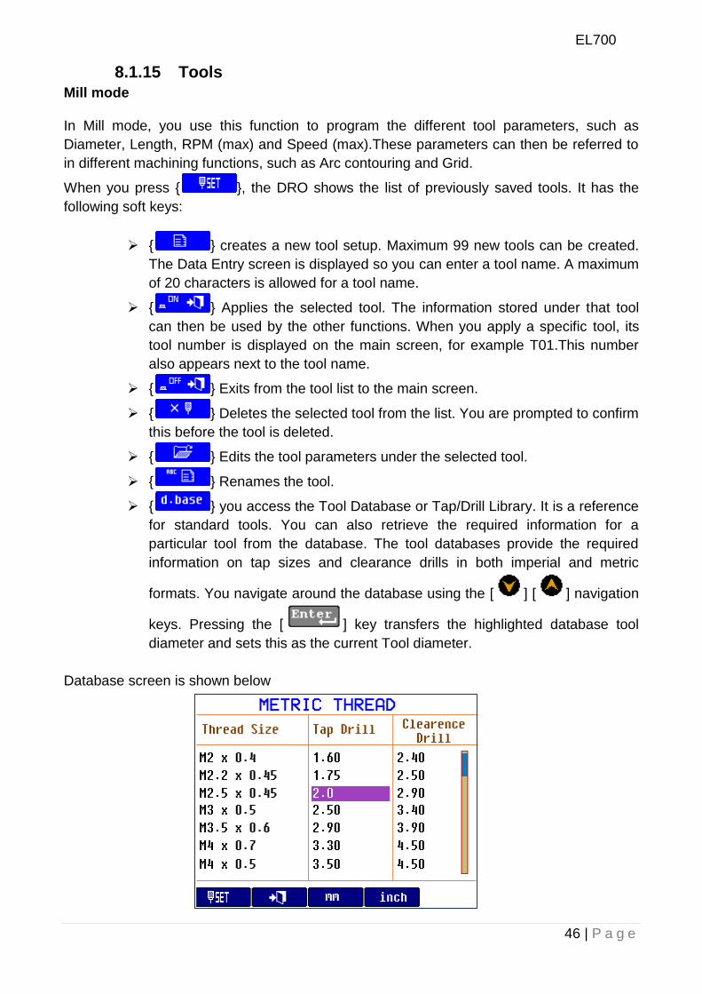
{ } you access the Tool Database or Tap/Drill Library. It is a reference
for standard tools. You can also retrieve the required information for a
particular tool from the database. The tool databases provide the required
information on tap sizes and clearance drills in both imperial and metric
formats. You navigate around the database using the [ ] [ ] navigation
keys. Pressing the [ ] key transfers the highlighted database tool
diameter and sets this as the current Tool diameter.
Database screen is shown below
EL700
47 | P a g e
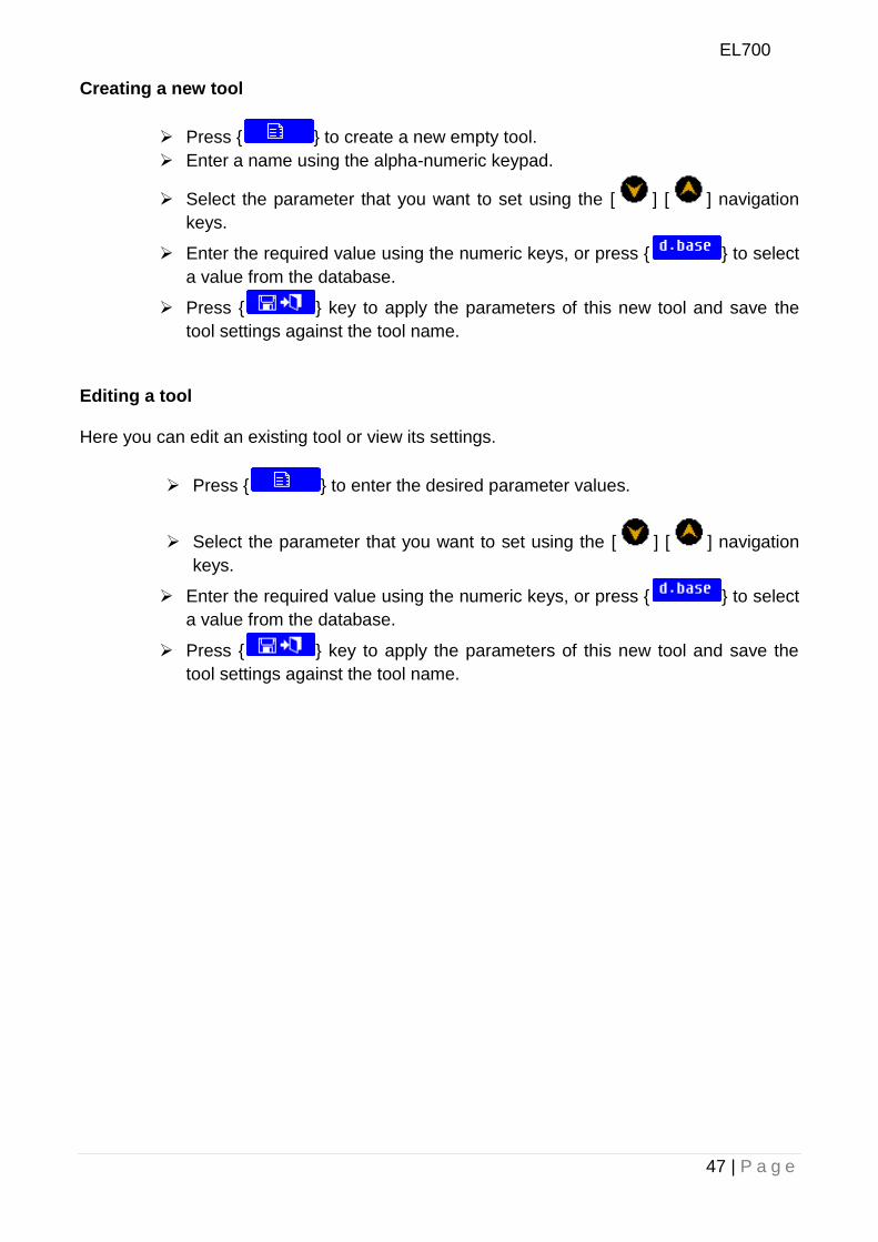
Creating a new tool
Press { } to create a new empty tool.
Enter a name using the alpha-numeric keypad.
Select the parameter that you want to set using the [ ] [ ] navigation
keys.
Enter the required value using the numeric keys, or press { } to select
a value from the database.
Press { } key to apply the parameters of this new tool and save the
tool settings against the tool name.
Editing a tool
Here you can edit an existing tool or view its settings.
Press { } to enter the desired parameter values.
Select the parameter that you want to set using the [ ] [ ] navigation
keys.
Enter the required value using the numeric keys, or press { } to select
a value from the database.
Press { } key to apply the parameters of this new tool and save the
tool settings against the tool name.
EL700
48 | P a g e
8.2 Lathe Machine Specific Functions:-
The following functions are available on { } when you select Lathe Machine:
Summing
Vectoring
Taper
Tools
Zero Approach (Refer section 8.1.12 From Mill Functions)
Job Timer (Refer section 8.1.13 From Mill Functions)
Shrinkage Factor (Refer section 8.1.14 From Mill Functions)
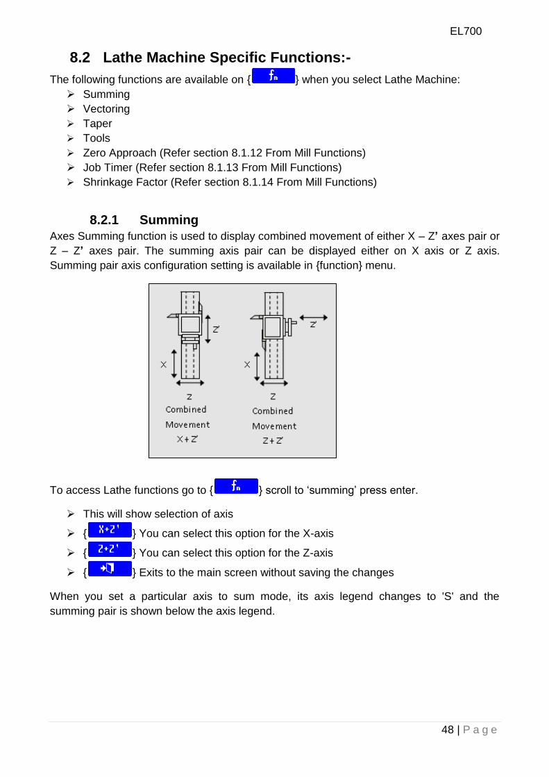
8.2.1 Summing
Axes Summing function is used to display combined movement of either X – Z’ axes pair or
Z – Z’ axes pair. The summing axis pair can be displayed either on X axis or Z axis.
Summing pair axis configuration setting is available in {function} menu.
To access Lathe functions go to { } scroll to „summing‟ press enter.
This will show selection of axis
{ } You can select this option for the X-axis
{ } You can select this option for the Z-axis
{ } Exits to the main screen without saving the changes
When you set a particular axis to sum mode, its axis legend changes to 'S' and the
summing pair is shown below the axis legend.
EL700
49 | P a g e
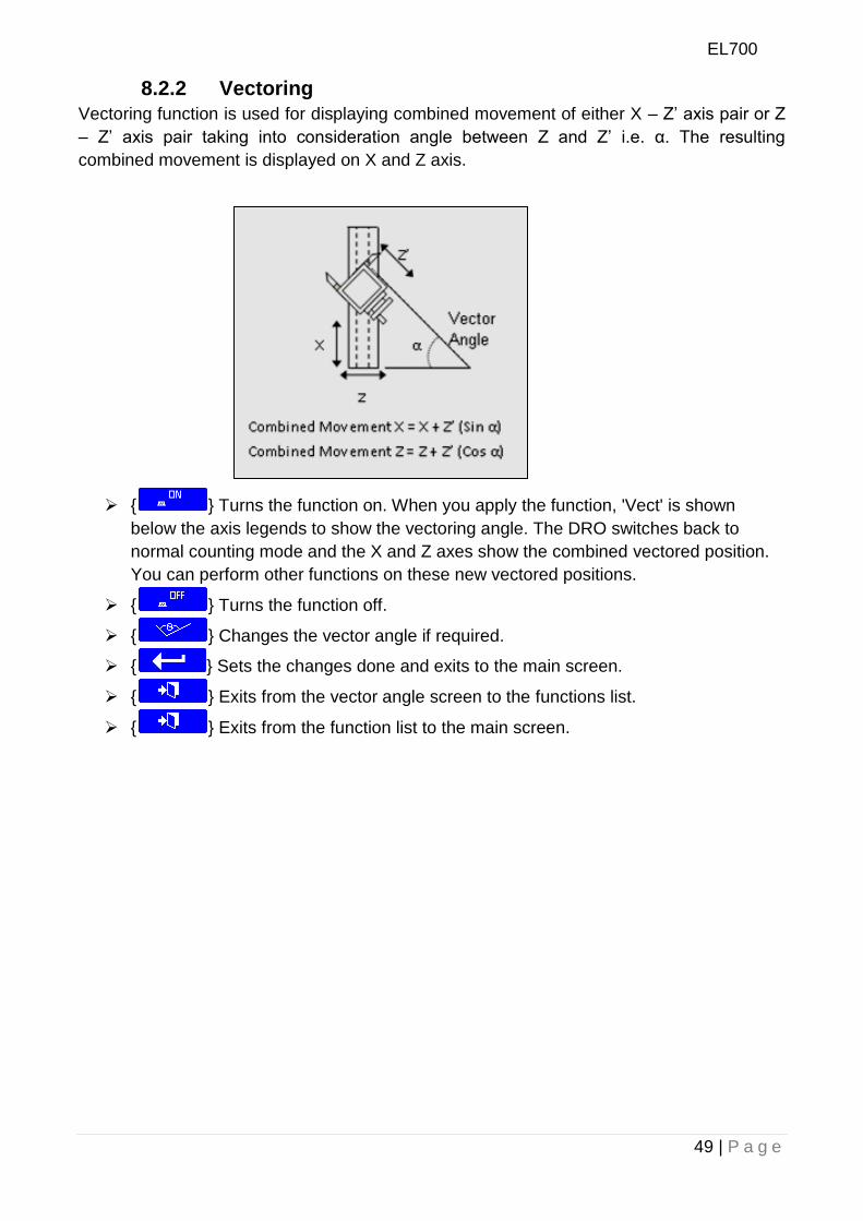
8.2.2 Vectoring
Vectoring function is used for displaying combined movement of either X – Z‟ axis pair or Z
– Z‟ axis pair taking into consideration angle between Z and Z‟ i.e. α. The resulting
combined movement is displayed on X and Z axis.
{ } Turns the function on. When you apply the function, 'Vect' is shown
below the axis legends to show the vectoring angle. The DRO switches back to
normal counting mode and the X and Z axes show the combined vectored position.
You can perform other functions on these new vectored positions.
{ } Turns the function off.
{ } Changes the vector angle if required.
{ } Sets the changes done and exits to the main screen.
{ } Exits from the vector angle screen to the functions list.
{ } Exits from the function list to the main screen.

EL700
50 | P a g e
8.2.3 Taper
Taper function allows user to calculate taper of the job. Measurements carried out in Taper
function are Radius of taper and Angle θ° of taper. Taper on axis setting is available in DRO
setup menu. This will select where to display taper angle.
Following soft keys are available:
{ } This key can be used to start the Taper function. The operator can
select the datum by pressing { } key. The display shows taper distance
(R) and taper angle () with reference to the selected datum position.
{ } Exits from the function list to the main screen.
8.2.4 Tools
Lathe mode
In Lathe mode, you use this function to program the different tool parameters, such as Diameter, Length, RPM (max) and Speed (max).These parameters can then be referred to in different machining functions, such as Arc contouring and Grid.
When you press { }, the DRO shows the list of previously saved tools. It has the
following soft keys:
{ } creates a new tool setup. Maximum 99 new tools can be created.
The Data Entry screen is displayed so you can enter a tool name. A maximum
of 20 characters is allowed for a tool name.
{ } Applies the selected tool. The information stored under that tool
can then be used by the other functions. When you apply a specific tool, its
tool number is displayed on the main screen, for example T01.This number
also appears next to the tool name.
{ } Exits from the tool list to the main screen.
{ } Deletes the selected tool from the list. You are prompted to confirm
this before the tool is deleted.
EL700
51 | P a g e
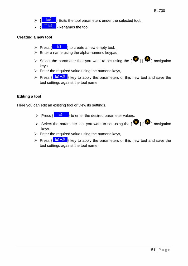
{ } Edits the tool parameters under the selected tool.
{ } Renames the tool.
Creating a new tool
Press { } to create a new empty tool.
Enter a name using the alpha-numeric keypad.
Select the parameter that you want to set using the [ ] [ ] navigation
keys.
Enter the required value using the numeric keys,
Press { } key to apply the parameters of this new tool and save the
tool settings against the tool name.
Editing a tool
Here you can edit an existing tool or view its settings.
Press { } to enter the desired parameter values.
Select the parameter that you want to set using the [ ] [ ] navigation
keys.
Enter the required value using the numeric keys,
Press { } key to apply the parameters of this new tool and save the
tool settings against the tool name.
EL700
52 | P a g e
9. Troubleshooting
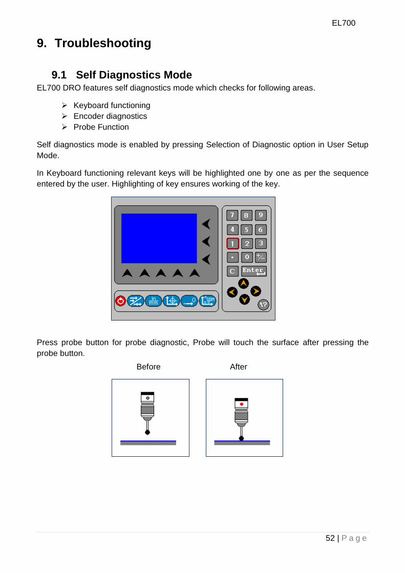
9.1 Self Diagnostics Mode EL700 DRO features self diagnostics mode which checks for following areas.
Keyboard functioning
Encoder diagnostics
Probe Function
Self diagnostics mode is enabled by pressing Selection of Diagnostic option in User Setup
Mode.
In Keyboard functioning relevant keys will be highlighted one by one as per the sequence
entered by the user. Highlighting of key ensures working of the key.
Press probe button for probe diagnostic, Probe will touch the surface after pressing the
probe button.
Before After
EL700
53 | P a g e
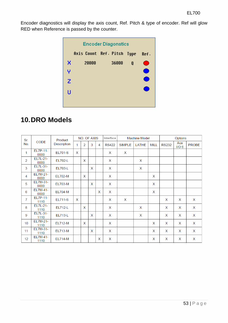
Encoder diagnostics will display the axis count, Ref. Pitch & type of encoder. Ref will glow
RED when Reference is passed by the counter.
10. DRO Models
EL700
54 | P a g e
Revision Date: 13-12-2011
Code No.: 0073-14-1650
Data Subject to change without notice.
Electronica Mechatronic Systems (India) Pvt. Ltd., Unit No. 37&44, Electronic Co-operative Estate, Pune-Satara road, Pune – 411009 Maharashtra, India Phone: +91 (020) 2422 4440, 2422 9398, Fax: +91 (020) 2422 1881 Email: [email protected] Web: www.electronicaems.com