Embed Size (px)
Citation preview
en
s
107_1542_TMA_0432_00_04 (20848).fm Page -1 Tuesday, January 10, 2012 4:42 PM
Elcometer107 • 1542
Cross Hatch Cutter
Operating Instruction
Ren
is a registered tradeAll other trademarks acknowledged
© Copyright Elcometer Limited. 200All rights reserved. No part of this Do transcribed, stored (in a retrievalsystem or otherwise) or translated i means (electronic, mechanical,magnetic, optical, manual or otherw of Elcometer Limited.A copy of this Instruction Manual is via www.elcometer.com.
Doc No. TMA-0432 Issue 04Text with Cover No. 20848
107_1542_TMA_0432_00_04 (20848).fm Page 0 Tuesday, January 10, 2012 4:42 PM
mark of Elcometer Limited..
9-2012.cument may be reproduced, transmitted,nto any language, in any form or by anyise) without the prior written permission available for download on our Website
R
1
en
Page
. . . . . . . . . . . . . . . . . . . . . . . . 2
. . . . . . . . . . . . . . . . . . . . . . . . 4
. . . . . . . . . . . . . . . . . . . . . . . . 5
. . . . . . . . . . . . . . . . . . . . . . . . 7
. . . . . . . . . . . . . . . . . . . . . . . 12
. . . . . . . . . . . . . . . . . . . . . . . 13
. . . . . . . . . . . . . . . . . . . . . . . 13
. . . . . . . . . . . . . . . . . . . . . . . 13
. . . . . . . . . . . . . . . . . . . . . . . 14
. . . . . . . . . . . . . . . . . . . . . . . 15
107_1542_TMA_0432_00_04 (20848).fm Page 1 Tuesday, January 10, 2012 4:42 PM
CONTENTS
Section
1 About this instrument. . . . . . . . . . . . . . . . . . . . . . . . . . . . . . . . . . . . . 2 Selecting the correct cutter blade . . . . . . . . . . . . . . . . . . . . . . . . . . . 3 Adjusting the cutter blades . . . . . . . . . . . . . . . . . . . . . . . . . . . . . . . . 4 Test procedure . . . . . . . . . . . . . . . . . . . . . . . . . . . . . . . . . . . . . . . . . . 5 ISO/JIS and ASTM standards. . . . . . . . . . . . . . . . . . . . . . . . . . . . . . . 6 Storage. . . . . . . . . . . . . . . . . . . . . . . . . . . . . . . . . . . . . . . . . . . . . . . . . 7 Maintenance . . . . . . . . . . . . . . . . . . . . . . . . . . . . . . . . . . . . . . . . . . . . 8 Technical specification. . . . . . . . . . . . . . . . . . . . . . . . . . . . . . . . . . . . 9 Spares . . . . . . . . . . . . . . . . . . . . . . . . . . . . . . . . . . . . . . . . . . . . . . . . . 10 Related equipment . . . . . . . . . . . . . . . . . . . . . . . . . . . . . . . . . . . . . . .
en
e to Elcometer.pection equipment for coatingsevelopment through application
rchase of this product you now. For more information visit our
for assessing the adhesion or
e made at right angles to eachually by comparing the grid of
coating.
llowing International Standards:CA T6, ISO 2409 supersedes
107_1542_TMA_0432_00_04 (20848).fm Page 2 Tuesday, January 10, 2012 4:42 PM
2
R
Thank you for your purchase of this Elcometer Cross Hatch Cutter. WelcomElcometer are world leaders in the design, manufacture and supply of insand concrete. Our products cover all aspects of coating inspection, from dto post application inspection.This Elcometer Cross Hatch Cutter is a world beating product. With the puhave access to the worldwide service and support network of Elcometerwebsite at www.elcometer.com
1 ABOUT THIS INSTRUMENT
The Elcometer Cross Hatch Cutter is a simple but effective instrument resistance to separation of coatings from substrates.The instrument is ideal for smooth coatings on flat surfaces.The cutter scores through the coating down to the substrate. Two cuts arother resulting in a grid of small squares. Adhesion is then assessed vissquares against Standards.A range of cutting blades is available for different thicknesses and types of
1.1 STANDARDSThe Elcometer Cross Hatch Cutter can be used in accordance with the foAS 1580.408.4, AS 3894.9, ASTM D3359-B, EN 13523-6 supersedes ECBS 3900-E6 & NF T30-038, ISO 16276-2, JIS K 5600-5-6.
R
3
en
ckage. Please ensure that thisnsult your local Environmental
lease take some time to readour Elcometer supplier if you
2
542 Cross Hatch Cutterauge for setting cutting blades
wrenchnstructions
e basic kit plus:
se
107_1542_TMA_0432_00_04 (20848).fm Page 3 Tuesday, January 10, 2012 4:42 PM
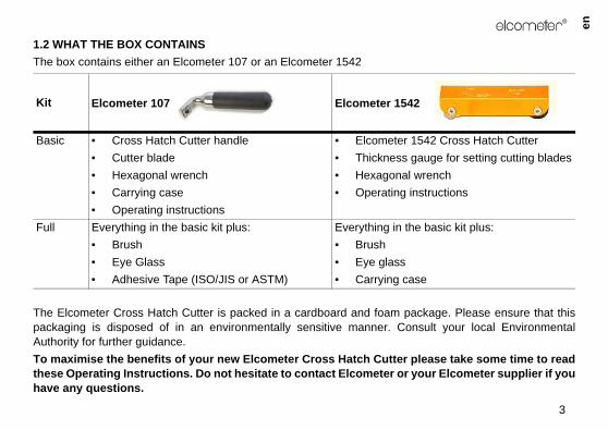
1.2 WHAT THE BOX CONTAINSThe box contains either an Elcometer 107 or an Elcometer 1542
The Elcometer Cross Hatch Cutter is packed in a cardboard and foam papackaging is disposed of in an environmentally sensitive manner. CoAuthority for further guidance.To maximise the benefits of your new Elcometer Cross Hatch Cutter pthese Operating Instructions. Do not hesitate to contact Elcometer or yhave any questions.
Kit Elcometer 107 Elcometer 154
Basic • Cross Hatch Cutter handle• Cutter blade• Hexagonal wrench• Carrying case• Operating instructions
• Elcometer 1• Thickness g• Hexagonal • Operating i
Full Everything in the basic kit plus:• Brush• Eye Glass• Adhesive Tape (ISO/JIS or ASTM)
Everything in th• Brush• Eye glass• Carrying ca
en
orrect blade.
r of cuts
ISO/JIS - Soft substrates (wood, plaster)
2 mm - 6 cuts2 mm - 6 cuts3 mm - 6 cuts
107_1542_TMA_0432_00_04 (20848).fm Page 4 Tuesday, January 10, 2012 4:42 PM
4
R
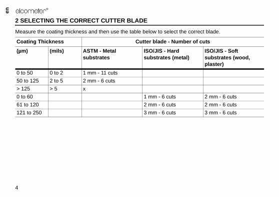
2 SELECTING THE CORRECT CUTTER BLADE
Measure the coating thickness and then use the table below to select the c
Coating Thickness Cutter blade - Numbe
(µm) (mils) ASTM - Metal substrates
ISO/JIS - Hard substrates (metal)
0 to 50 0 to 2 1 mm - 11 cuts50 to 125 2 to 5 2 mm - 6 cuts> 125 > 5 x0 to 60 1 mm - 6 cuts61 to 120 2 mm - 6 cuts121 to 250 3 mm - 6 cuts
R
5
en
x1
x2
x3
x4
y1
y2
y3
y4
107_1542_TMA_0432_00_04 (20848).fm Page 5 Tuesday, January 10, 2012 4:42 PM
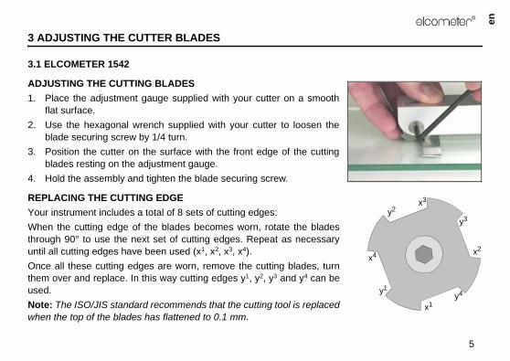
3 ADJUSTING THE CUTTER BLADES
3.1 ELCOMETER 1542
ADJUSTING THE CUTTING BLADES1. Place the adjustment gauge supplied with your cutter on a smooth
flat surface.2. Use the hexagonal wrench supplied with your cutter to loosen the
blade securing screw by 1/4 turn.3. Position the cutter on the surface with the front edge of the cutting
blades resting on the adjustment gauge.4. Hold the assembly and tighten the blade securing screw.
REPLACING THE CUTTING EDGEYour instrument includes a total of 8 sets of cutting edges:When the cutting edge of the blades becomes worn, rotate the bladesthrough 90° to use the next set of cutting edges. Repeat as necessaryuntil all cutting edges have been used (x1, x2, x3, x4).Once all these cutting edges are worn, remove the cutting blades, turnthem over and replace. In this way cutting edges y1, y2, y3 and y4 can beused.Note: The ISO/JIS standard recommends that the cutting tool is replacedwhen the top of the blades has flattened to 0.1 mm.
en
er blade
107_1542_TMA_0432_00_04 (20848).fm Page 6 Tuesday, January 10, 2012 4:42 PM
6
R
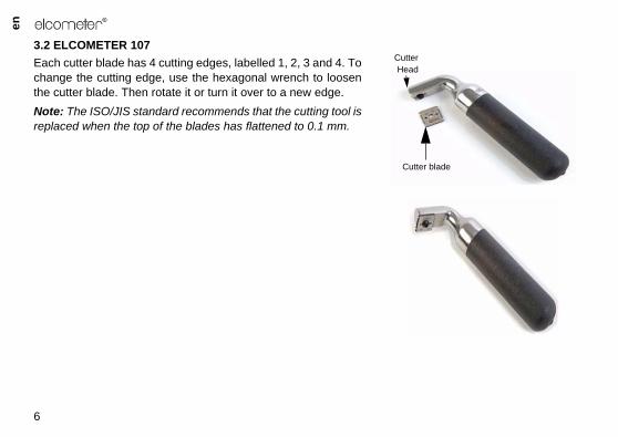
3.2 ELCOMETER 107Each cutter blade has 4 cutting edges, labelled 1, 2, 3 and 4. Tochange the cutting edge, use the hexagonal wrench to loosenthe cutter blade. Then rotate it or turn it over to a new edge.Note: The ISO/JIS standard recommends that the cutting tool isreplaced when the top of the blades has flattened to 0.1 mm.
Cutt
CutterHead
R
7
en
ool on the sample, press down tool towards you in one
t to make a series of parallel ly 20 mm long. Apply sufficient e that you cut through the strate.
107_1542_TMA_0432_00_04 (20848).fm Page 7 Tuesday, January 10, 2012 4:42 PM
4 TEST PROCEDURE
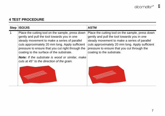
Step ISO/JIS ASTM1 Place the cutting tool on the sample, press down
gently and pull the tool towards you in one steady movement to make a series of parallel cuts approximately 20 mm long. Apply sufficient pressure to ensure that you cut right through the coating to the surface of the substrate.Note: If the substrate is wood or similar, makecuts at 45° to the direction of the grain.
Place the cutting tgently and pull thesteady movemencuts approximatepressure to ensurcoating to the sub
en
ool on the sample at 90° to the t step (1) to create a lattice ting.
move detached flakes or .
oating.
107_1542_TMA_0432_00_04 (20848).fm Page 8 Tuesday, January 10, 2012 4:42 PM
8
R
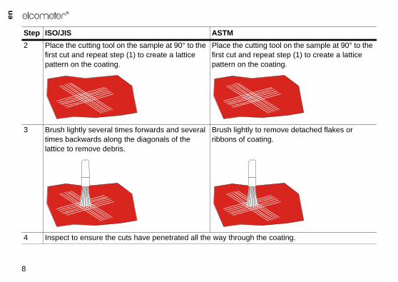
2 Place the cutting tool on the sample at 90° to the first cut and repeat step (1) to create a lattice pattern on the coating.
Place the cutting tfirst cut and repeapattern on the coa
3 Brush lightly several times forwards and several times backwards along the diagonals of the lattice to remove debris.
Brush lightly to reribbons of coating
4 Inspect to ensure the cuts have penetrated all the way through the c
Step ISO/JIS ASTM
R
9
en
adhesive tape (see “Spares” ove and discard two complete
tape. Remove an additional steady rate and cut a piece mm from this length.ce of tape over the lattice and using a finger. Rub the tape aser on the end of a pencil to sion between the tape and the
107_1542_TMA_0432_00_04 (20848).fm Page 9 Tuesday, January 10, 2012 4:42 PM
5 If the substrate is soft, jump to step (10).If the substrate is hard or wood, proceed to the next step (6)
-
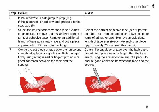
6 Select the correct adhesive tape (see “Spares” on page 14). Remove and discard two complete turns of adhesive tape. Remove an additional length of tape at a steady rate and cut a piece approximately 75 mm from this length.
Select the correcton page 14). Remturns of adhesivelength of tape at aapproximately 75
7 Centre the cut piece of tape over the lattice and smooth into place using a finger. Rub the tape firmly using a finger nail or finger tip to ensure good adhesion between the tape and the coating.
Centre the cut piesmooth into placefirmly using the erensure good adhecoating.
Step ISO/JIS ASTM
en
s (± 30 seconds) of applying the tape by pulling in a single an angle of 180° to the coating
180°
107_1542_TMA_0432_00_04 (20848).fm Page 10 Tuesday, January 10, 2012 4:42 PM
10
R
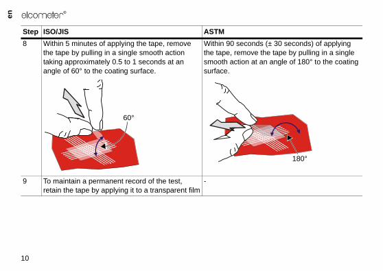
8 Within 5 minutes of applying the tape, remove the tape by pulling in a single smooth action taking approximately 0.5 to 1 seconds at an angle of 60° to the coating surface.
Within 90 secondthe tape, remove smooth action at surface.
9 To maintain a permanent record of the test, retain the tape by applying it to a transparent film
-
Step ISO/JIS ASTM
60°
R
11
en
ing adhesion by viewing theg an illuminated magnifier.
ce of cuts with the ISO/JIS andshown in “ISO/JIS and ASTMe 12.
107_1542_TMA_0432_00_04 (20848).fm Page 11 Tuesday, January 10, 2012 4:42 PM
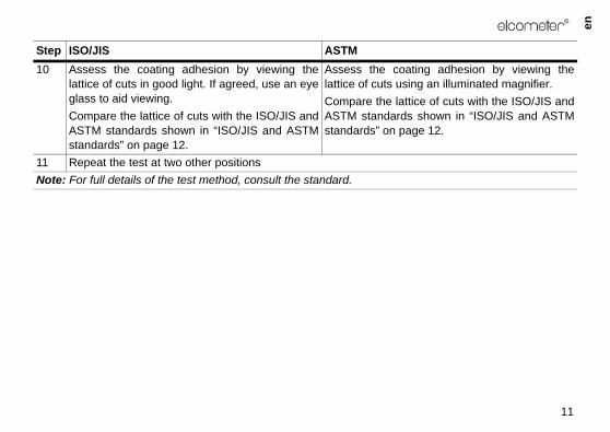
10 Assess the coating adhesion by viewing thelattice of cuts in good light. If agreed, use an eyeglass to aid viewing.Compare the lattice of cuts with the ISO/JIS andASTM standards shown in “ISO/JIS and ASTMstandards” on page 12.
Assess the coatlattice of cuts usinCompare the lattiASTM standards standards” on pag
11 Repeat the test at two other positionsNote: For full details of the test method, consult the standard.
Step ISO/JIS ASTM
en
ning a copy of the latest version
ISO/JIS ASTMres of the lattice 0 5B
uts. A cross cut 1 4B
ons of the cuts. tly greater than
2 3B
olly in large f the squares. A tly greater than
3 2B
ons and/or significantly cted.
4 1B
ation 4 (1B). 5 0B
107_1542_TMA_0432_00_04 (20848).fm Page 12 Tuesday, January 10, 2012 4:42 PM
12
R
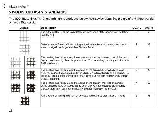
5 ISO/JIS AND ASTM STANDARDS
The ISO/JIS and ASTM Standards are reproduced below. We advise obtaiof these Standards.
Surface DescriptionThe edges of the cuts are completely smooth; none of the squais detached.
Detachment of flakes of the coating at the intersections of the carea not significantly greater than 5% is affected.
The coating has flaked along the edges and/or at the intersectiA cross cut area significantly greater than 5%, but not significan15% is affected.
The coating has flaked along the edges of the cuts partly or whribbons, and/or it has flaked partly or wholly on different parts ocross cut area significantly greater than 15%, but not significan35%, is affected.The coating has flaked along the edges of the cuts in large ribbsome squares have detached partly or wholly. A cross cut areagreater than 35%, but not significantly greater than 65%, is affe
Any degree of flaking that cannot be classified even by classific
R
13
en
service under normal operatingunder these conditions.plier.
omponents. In the unlikely eventer or directly to Elcometer.
542minium handlemm x 35 mm
5")
107_1542_TMA_0432_00_04 (20848).fm Page 13 Tuesday, January 10, 2012 4:42 PM
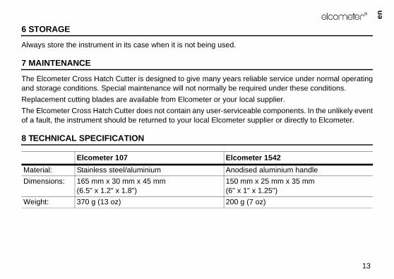
6 STORAGE
Always store the instrument in its case when it is not being used.
7 MAINTENANCE
The Elcometer Cross Hatch Cutter is designed to give many years reliableand storage conditions. Special maintenance will not normally be required Replacement cutting blades are available from Elcometer or your local supThe Elcometer Cross Hatch Cutter does not contain any user-serviceable cof a fault, the instrument should be returned to your local Elcometer suppli
8 TECHNICAL SPECIFICATION
Elcometer 107 Elcometer 1Material: Stainless steel/aluminium Anodised aluDimensions: 165 mm x 30 mm x 45 mm
(6.5" x 1.2" x 1.8")150 mm x 25(6" x 1" x 1.2
Weight: 370 g (13 oz) 200 g (7 oz)
en
lcometer supplier or direct from
107_1542_TMA_0432_00_04 (20848).fm Page 14 Tuesday, January 10, 2012 4:42 PM
14
R
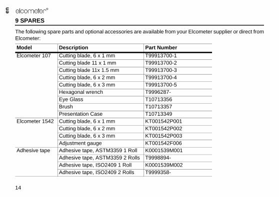
9 SPARES
The following spare parts and optional accessories are available from your EElcometer:
Model Description Part NumberElcometer 107 Cutting blade, 6 x 1 mm T99913700-1
Cutting blade 11 x 1 mm T99913700-2Cutting blade 11x 1.5 mm T99913700-3Cutting blade, 6 x 2 mm T99913700-4Cutting blade, 6 x 3 mm T99913700-5Hexagonal wrench T9996287-Eye Glass T10713356Brush T10713357Presentation Case T10713349
Elcometer 1542 Cutting blade, 6 x 1 mm KT001542P001Cutting blade, 6 x 2 mm KT001542P002Cutting blade, 6 x 3 mm KT001542P003Adjustment gauge KT001542F006
Adhesive tape Adhesive tape, ASTM3359 1 Roll K0001539M001Adhesive tape, ASTM3359 2 Rolls T9998894-Adhesive tape, ISO2409 1 Roll K0001539M002Adhesive tape, ISO2409 2 Rolls T9999358-
R
15
en
e range of other coating testingit from the following Elcometer
elcometer.com
107_1542_TMA_0432_00_04 (20848).fm Page 15 Tuesday, January 10, 2012 4:42 PM
10 RELATED EQUIPMENT
In addition to the Elcometer Cross Hatch Cutter, Elcometer produces a widequipment. Users of the Elcometer Cross Hatch Cutter may also benefproduct ranges:• Elasticity and Resistance Deformation Testers• Paint Inspection Gauges• Coatings Thickness Gauges• Appearance Testers• Washability, Brushability and Abrasion TestersFor further information contact Elcometer, your local supplier or visit www.


![[HATCH! PROGRAM] HATCH! FAIR Overview](https://img.pdfslide.net/doc/110x75/554bf5e9b4c9055a368b553f/hatch-program-hatch-fair-overview.jpg)