Embed Size (px)
Citation preview
lable at ScienceDirect
Vacuum 86 (2012) 953e959
Contents lists avai
Vacuum
journal homepage: www.elsevier .com/locate/vacuum
Electrical and mechanical properties of nano-structured TiN coatings depositedby vacuum cold spray
Y.-Y. Wang a,*, Y. Liu a, C.-J. Li a, G.-J. Yang a, K. Kusumoto b
a State Key Laboratory for Mechanical Behavior of Materials, Xi’an Jiaotong University, Shaanxi 710049, ChinabDepartment of Mechanical Systems Engineering, Engineering Faculty of Gunma University, Gunma 376 0052, Japan
a r t i c l e i n f o
Article history:Received 31 October 2010Received in revised form16 May 2011Accepted 22 June 2011
Keywords:TiN coatingVacuum cold sprayElectrical propertyMicrohardnessFracture toughnessPorosity
* Corresponding author. Tel.: þ86 29 82665299; faE-mail address: [email protected] (Y.-Y. W
0042-207X/$ e see front matter � 2011 Elsevier Ltd.doi:10.1016/j.vacuum.2011.06.026
a b s t r a c t
Titanium nitride (TiN) coatings were fabricated by vacuum cold spray (VCS) process at room temperaturewith nano-sized starting powder (about 20 nm in size). The microstructure of the powder and coatingwas examined by scanning electron microscope and X-ray diffraction. The porosity and pore distributionof the VCS TiN coatings were measured by the N2 adsorption-desorption method. The microhardness andfracture toughness of the coatings were evaluated by using the micro-indentation technique. The sheetresistance and electrical resistivity of the coatings were characterized by the four-point probe method.The results show that the sheet resistance of coatings is significantly reduced from 13565 to 127 U withincreasing the coating thickness. A minimum electrical resistivity of 1.8 � 10�3 U m is achieved. The VCSTiN coatings with high porosity ranging from 58.3 to 67.6% exhibit low hardness of 279e490 HV andrelatively good fracture toughness of about 3.12 MPa m1/2.
� 2011 Elsevier Ltd. All rights reserved.
1. Introduction
Titanium nitride (TiN) coatings are extensively used formachining tool protection, decoration and diffusion barriers due totheir superior properties, such as high hardness, good wear andcorrosion resistances and unique electrical characteristics [1]. Theconventional preparation technologies of TiN coatings mainly focuson physical vapor deposition (PVD), chemical vapor deposition(CVD) and reactive plasma spraying (RPS). However, PVD and CVDprocesses have relatively low deposition efficiency as well asdifficult control of the ratio of Ti/N. Even though RPS can providehigher deposition efficiency, the high temperature oxidation cannot be ignored during the process [2e4].
In order to figure out the problem, a new approach for ceramiccoating fabrication at room temperature is needed urgently.Vacuum cold spray is a novel and promising spray technologywhich enables deposition on various substrates such as metals,ceramics and plastics. The method is based on shock-loadingsolidification. In the process, ultralfine ceramic particles are accel-erated up to a very high velocity by carrier gas through a micro-orifice nozzle and subsequently impact and form a coating ontoa substrate in a chamber at vacuum circumstances at room
x: þ86 29 83237910.ang).
All rights reserved.
temperature. Because the solid ceramic powder is mixed witha carrier gas to form an aerosol flow, the technique is also calledaerosol deposition (AD) method. VCS has received considerableconcerns for its outstanding advantages: (1) Due to the low depo-sition temperature (room temperature), the microstructure of thefeedstock can be transferred into the as-deposited coating withoutany crystal grain growth or structural changes. (2) The high depo-sition efficiency (ranged from several mm/min to several tens of mm/min) [5,6].
Sintered ceramic powders with a particle size range of about0.08e2 mmare typically used as the deposition particles to fabricatedense coating due to room temperature impact consolidation(RTIC) [6]. In this paper, a tentative exploration concerning nano-sized powders of 20 nm in size used as feedstock during vacuumcold spray process was designed. The effects of particle size, gasflow and deposition chamber pressure on the microstructure aswell as the electrical and mechanical properties of the VCS TiNcoatings were investigated.
2. Experimental materials and procedures
2.1. Materials
The feedstock was commercially available nano-sized TiNpowders. The morphology is shown in Fig. 1. It is found that the
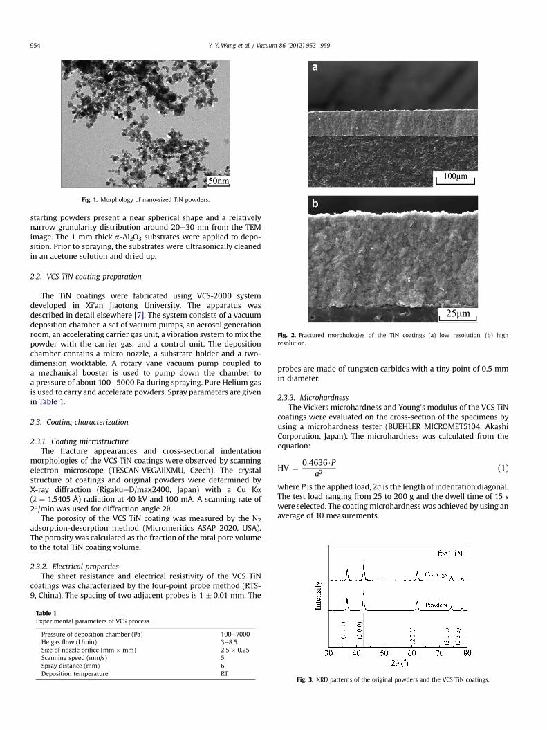
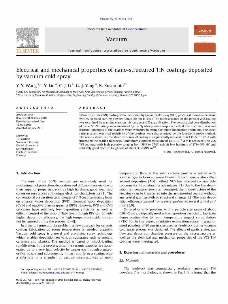
Fig. 1. Morphology of nano-sized TiN powders.
Fig. 2. Fractured morphologies of the TiN coatings (a) low resolution, (b) highresolution.
Y.-Y. Wang et al. / Vacuum 86 (2012) 953e959954
starting powders present a near spherical shape and a relativelynarrow granularity distribution around 20e30 nm from the TEMimage. The 1 mm thick a-Al2O3 substrates were applied to depo-sition. Prior to spraying, the substrates were ultrasonically cleanedin an acetone solution and dried up.
2.2. VCS TiN coating preparation
The TiN coatings were fabricated using VCS-2000 systemdeveloped in Xi’an Jiaotong University. The apparatus wasdescribed in detail elsewhere [7]. The system consists of a vacuumdeposition chamber, a set of vacuum pumps, an aerosol generationroom, an accelerating carrier gas unit, a vibration system tomix thepowder with the carrier gas, and a control unit. The depositionchamber contains a micro nozzle, a substrate holder and a two-dimension worktable. A rotary vane vacuum pump coupled toa mechanical booster is used to pump down the chamber toa pressure of about 100e5000 Pa during spraying. Pure Helium gasis used to carry and accelerate powders. Spray parameters are givenin Table 1.
2.3. Coating characterization
2.3.1. Coating microstructureThe fracture appearances and cross-sectional indentation
morphologies of the VCS TiN coatings were observed by scanningelectron microscope (TESCAN-VEGAIIXMU, Czech). The crystalstructure of coatings and original powders were determined byX-ray diffraction (RigakueD/max2400, Japan) with a Cu Ka(l ¼ 1.5405 Å) radiation at 40 kV and 100 mA. A scanning rate of2�/min was used for diffraction angle 2q.
The porosity of the VCS TiN coating was measured by the N2adsorption-desorption method (Micromeritics ASAP 2020, USA).The porosity was calculated as the fraction of the total pore volumeto the total TiN coating volume.
2.3.2. Electrical propertiesThe sheet resistance and electrical resistivity of the VCS TiN
coatings was characterized by the four-point probe method (RTS-9, China). The spacing of two adjacent probes is 1 � 0.01 mm. The
Table 1Experimental parameters of VCS process.
Pressure of deposition chamber (Pa) 100e7000He gas flow (L/min) 3e8.5Size of nozzle orifice (mm � mm) 2.5 � 0.25Scanning speed (mm/s) 5Spray distance (mm) 6Deposition temperature RT
probes are made of tungsten carbides with a tiny point of 0.5 mmin diameter.
2.3.3. MicrohardnessThe Vickers microhardness and Young’s modulus of the VCS TiN
coatings were evaluated on the cross-section of the specimens byusing a microhardness tester (BUEHLER MICROMET5104, AkashiCorporation, Japan). The microhardness was calculated from theequation:
HV ¼ 0:4636$Pa2
(1)
where P is the applied load, 2a is the length of indentation diagonal.The test load ranging from 25 to 200 g and the dwell time of 15 swere selected. The coatingmicrohardness was achieved by using anaverage of 10 measurements.
Fig. 3. XRD patterns of the original powders and the VCS TiN coatings.

Fig. 4. Effect of coating thickness on the sheet resistance of VCS TiN coatings.
Table 3Sheet resistance of TiN coatings vs. gas flow at deposition chamberpressure of 2500 Pa.
Gas flow (L/min) Sheet resistance (U)
3 >106
4.5 63416 9547.5 140
Y.-Y. Wang et al. / Vacuum 86 (2012) 953e959 955
2.3.4. Young’s modulusThe Knoop indentation test provides a practical way to deter-
mine the Young’s modulus of coating from the measurement of theresidual imprint diagonals ratio. The principle of this method isbased on the elastic response of materials when a loading indenteris applied to the specimen. A rough estimate of Young’s moduluscan be obtained with an empirical relationship [8]:
b0
a0¼ b
a� a
HVE
(2)
where HV is the corresponding hardness, the long diagonal a is 7.11times larger than the short one b, b’/a’ is the ratio of the remainingimprint diagonals. The constant a is 0.45. Knoop indentations wereperformed on the cross-section of the coatings at a load of 50 g, theb’/a’ values were obtained by using an average of 5 Knoopindentations.
2.3.5. Fracture toughnessThe indentation test is applied to the fracture toughness (KIC)
determination. The Vickers load is put on a polished cross-sectionof the coating and the cracks are induced from the corners ofindentations. The following formula is utilized for the determina-tion of the fracture toughness [9]:
KIC ¼ 0:016ðE=HÞ1=2�P=C3=2
�(3)
where E is the Young’s modulus of the coating, H the hardness ofthe coating, C the crack length, and P the applied load.
3. Results
3.1. Microstructure of TiN coatings
The coatings were deposited with various gas flows andchamber pressures to obtain a series of thickness ranging from 10to 100 mm. Fig. 2 shows the typical fractured morphologies of theVCS TiN coatings deposited on Al2O3 substrates. Clearly, the
Table 2Sheet resistance of TiN coatings vs. deposition chamber pressure at gas flow of 3 L/min.
Deposition chamber pressure (Pa) Sheet resistance (U)
100 5323200 21,248400 73,692600 >106
1000 >106
5000 >106
coatings were uniform in thickness and presented good adhesion tothe substrate.
3.2. Crystal structure of VCS TiN coatings
Fig. 3 shows the XRD patterns of the original powders and theVCS TiN coatings. The two X-ray diffraction lines are perfectlymatched. Peak broadening due to nano-sized crystal grain in thepowders does not disappear and there is not any new peak in thecoatings. It is indicated that the nano-structure of the ceramicpowder retains in the as-deposited coating without any crystalgrain growth or structural changes because the ceramic particlesare deposited in a solid state to form the coatings at roomtemperature.
3.3. Electrical properties of VCS TiN coatings
The sheet resistance of the VCS TiN coatings remarkably reducesfrom 13565 to 127Uwith increasing the coating thickness from 5 to27 mm (shown in Fig. 4). The minimum sheet resistance of VCS TiNcoating is lower than that of the TiN film deposited by CVD [10].Obviously, VCS is an excellent approach to control the sheet resis-tance of coating by adjusting the coating thickness.
Gas flow was kept at 3 L/min and the deposition chamberpressures were regulated. The effect of the deposition chamberpressures on the sheet resistance of coating is listed in Table 2. Theresult reveals that the sheet resistance of the coating with thicknessof 12 mm increaseswith increasing the chamber pressure.When thechamber pressure is over 600 Pa, the sheet resistance exceeds themaximum range of the four-point-probe apparatus RTS-9. The datalisted in Table 3 shows the relationship between the sheet resis-tance of the coatings with thickness of 25 mm and the gas flowswhen the chamber pressure was kept at 2500 Pa. It indicates that
Fig. 5. Effect of the chamber pressure and gas flow on the electrical resistivity of theVCS TiN coatings.
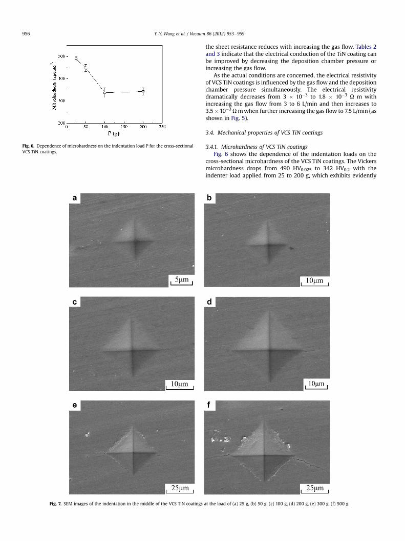
Fig. 6. Dependence of microhardness on the indentation load P for the cross-sectionalVCS TiN coatings.
Fig. 7. SEM images of the indentation in the middle of the VCS TiN coatings
Y.-Y. Wang et al. / Vacuum 86 (2012) 953e959956
the sheet resistance reduces with increasing the gas flow. Tables 2and 3 indicate that the electrical conduction of the TiN coating canbe improved by decreasing the deposition chamber pressure orincreasing the gas flow.
As the actual conditions are concerned, the electrical resistivityof VCS TiN coatings is influenced by the gas flow and the depositionchamber pressure simultaneously. The electrical resistivitydramatically decreases from 3 � 10�3 to 1.8 � 10�3 U m withincreasing the gas flow from 3 to 6 L/min and then increases to3.5�10�3Umwhen further increasing the gas flow to 7.5 L/min (asshown in Fig. 5).
3.4. Mechanical properties of VCS TiN coatings
3.4.1. Microhardness of VCS TiN coatingsFig. 6 shows the dependence of the indentation loads on the
cross-sectional microhardness of the VCS TiN coatings. The Vickersmicrohardness drops from 490 HV0.025 to 342 HV0.2 with theindenter load applied from 25 to 200 g, which exhibits evidently
at the load of (a) 25 g, (b) 50 g, (c) 100 g, (d) 200 g, (e) 300 g, (f) 500 g.
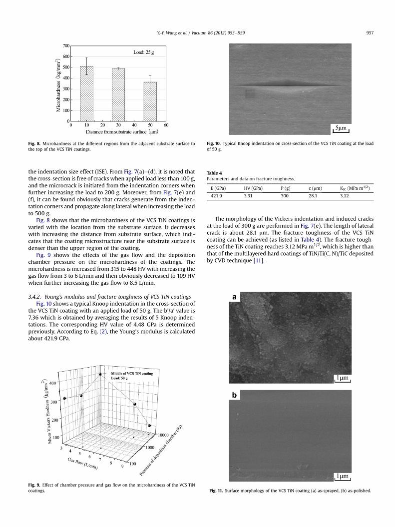
Fig. 8. Microhardness at the different regions from the adjacent substrate surface tothe top of the VCS TiN coatings.
Fig. 10. Typical Knoop indentation on cross-section of the VCS TiN coating at the loadof 50 g.
Table 4Parameters and data on fracture toughness.
E (GPa) HV (GPa) P (g) c (mm) KIC (MPa m1/2)
421.9 3.31 300 28.1 3.12
Y.-Y. Wang et al. / Vacuum 86 (2012) 953e959 957
the indentation size effect (ISE). From Fig. 7(a)e(d), it is noted thatthe cross-section is free of cracks when applied load less than 100 g,and the microcrack is initiated from the indentation corners whenfurther increasing the load to 200 g. Moreover, from Fig. 7(e) and(f), it can be found obviously that cracks generate from the inden-tation corners and propagate along lateral when increasing the loadto 500 g.
Fig. 8 shows that the microhardness of the VCS TiN coatings isvaried with the location from the substrate surface. It decreaseswith increasing the distance from substrate surface, which indi-cates that the coating microstructure near the substrate surface isdenser than the upper region of the coating.
Fig. 9 shows the effects of the gas flow and the depositionchamber pressure on the microhardness of the coatings. Themicrohardness is increased from 315 to 448 HV with increasing thegas flow from 3 to 6 L/min and then obviously decreased to 109 HVwhen further increasing the gas flow to 8.5 L/min.
3.4.2. Young’s modulus and fracture toughness of VCS TiN coatingsFig. 10 shows a typical Knoop indentation in the cross-section of
the VCS TiN coating with an applied load of 50 g. The b’/a’ value is7.36 which is obtained by averaging the results of 5 Knoop inden-tations. The corresponding HV value of 4.48 GPa is determinedpreviously. According to Eq. (2), the Young’s modulus is calculatedabout 421.9 GPa.
Fig. 9. Effect of chamber pressure and gas flow on the microhardness of the VCS TiNcoatings.
The morphology of the Vickers indentation and induced cracksat the load of 300 g are performed in Fig. 7(e). The length of lateralcrack is about 28.1 mm. The fracture toughness of the VCS TiNcoating can be achieved (as listed in Table 4). The fracture tough-ness of the TiN coating reaches 3.12 MPa m1/2, which is higher thanthat of the multilayered hard coatings of TiN/Ti(C, N)/TiC depositedby CVD technique [11].
Fig. 11. Surface morphology of the VCS TiN coating (a) as-sprayed, (b) as-polished.
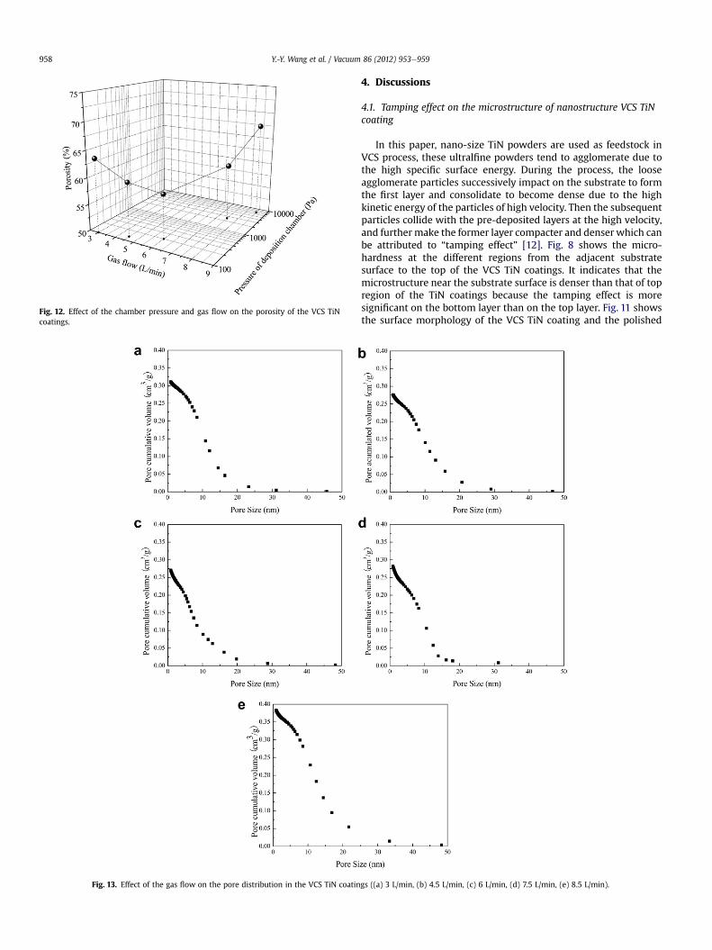
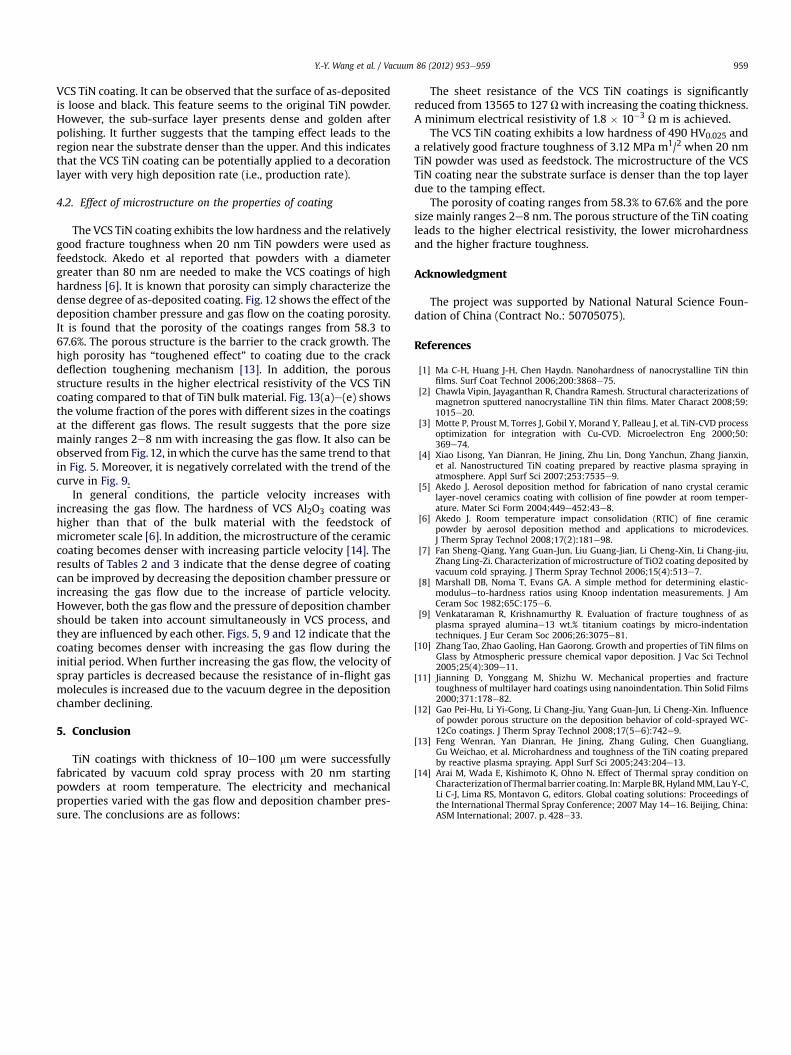
Fig. 12. Effect of the chamber pressure and gas flow on the porosity of the VCS TiNcoatings.
Fig. 13. Effect of the gas flow on the pore distribution in the VCS TiN coatin
Y.-Y. Wang et al. / Vacuum 86 (2012) 953e959958
4. Discussions
4.1. Tamping effect on the microstructure of nanostructure VCS TiNcoating
In this paper, nano-size TiN powders are used as feedstock inVCS process, these ultralfine powders tend to agglomerate due tothe high specific surface energy. During the process, the looseagglomerate particles successively impact on the substrate to formthe first layer and consolidate to become dense due to the highkinetic energy of the particles of high velocity. Then the subsequentparticles collide with the pre-deposited layers at the high velocity,and furthermake the former layer compacter and denser which canbe attributed to “tamping effect” [12]. Fig. 8 shows the micro-hardness at the different regions from the adjacent substratesurface to the top of the VCS TiN coatings. It indicates that themicrostructure near the substrate surface is denser than that of topregion of the TiN coatings because the tamping effect is moresignificant on the bottom layer than on the top layer. Fig. 11 showsthe surface morphology of the VCS TiN coating and the polished
gs ((a) 3 L/min, (b) 4.5 L/min, (c) 6 L/min, (d) 7.5 L/min, (e) 8.5 L/min).
Y.-Y. Wang et al. / Vacuum 86 (2012) 953e959 959
VCS TiN coating. It can be observed that the surface of as-depositedis loose and black. This feature seems to the original TiN powder.However, the sub-surface layer presents dense and golden afterpolishing. It further suggests that the tamping effect leads to theregion near the substrate denser than the upper. And this indicatesthat the VCS TiN coating can be potentially applied to a decorationlayer with very high deposition rate (i.e., production rate).
4.2. Effect of microstructure on the properties of coating
The VCS TiN coating exhibits the low hardness and the relativelygood fracture toughness when 20 nm TiN powders were used asfeedstock. Akedo et al reported that powders with a diametergreater than 80 nm are needed to make the VCS coatings of highhardness [6]. It is known that porosity can simply characterize thedense degree of as-deposited coating. Fig. 12 shows the effect of thedeposition chamber pressure and gas flow on the coating porosity.It is found that the porosity of the coatings ranges from 58.3 to67.6%. The porous structure is the barrier to the crack growth. Thehigh porosity has “toughened effect” to coating due to the crackdeflection toughening mechanism [13]. In addition, the porousstructure results in the higher electrical resistivity of the VCS TiNcoating compared to that of TiN bulk material. Fig. 13(a)e(e) showsthe volume fraction of the pores with different sizes in the coatingsat the different gas flows. The result suggests that the pore sizemainly ranges 2e8 nm with increasing the gas flow. It also can beobserved from Fig. 12, inwhich the curve has the same trend to thatin Fig. 5. Moreover, it is negatively correlated with the trend of thecurve in Fig. 9.
In general conditions, the particle velocity increases withincreasing the gas flow. The hardness of VCS Al2O3 coating washigher than that of the bulk material with the feedstock ofmicrometer scale [6]. In addition, the microstructure of the ceramiccoating becomes denser with increasing particle velocity [14]. Theresults of Tables 2 and 3 indicate that the dense degree of coatingcan be improved by decreasing the deposition chamber pressure orincreasing the gas flow due to the increase of particle velocity.However, both the gas flow and the pressure of deposition chambershould be taken into account simultaneously in VCS process, andthey are influenced by each other. Figs. 5, 9 and 12 indicate that thecoating becomes denser with increasing the gas flow during theinitial period. When further increasing the gas flow, the velocity ofspray particles is decreased because the resistance of in-flight gasmolecules is increased due to the vacuum degree in the depositionchamber declining.
5. Conclusion
TiN coatings with thickness of 10e100 mm were successfullyfabricated by vacuum cold spray process with 20 nm startingpowders at room temperature. The electricity and mechanicalproperties varied with the gas flow and deposition chamber pres-sure. The conclusions are as follows:
The sheet resistance of the VCS TiN coatings is significantlyreduced from 13565 to 127 Uwith increasing the coating thickness.A minimum electrical resistivity of 1.8 � 10�3 U m is achieved.
The VCS TiN coating exhibits a low hardness of 490 HV0.025 anda relatively good fracture toughness of 3.12 MPa m1/2 when 20 nmTiN powder was used as feedstock. The microstructure of the VCSTiN coating near the substrate surface is denser than the top layerdue to the tamping effect.
The porosity of coating ranges from 58.3% to 67.6% and the poresize mainly ranges 2e8 nm. The porous structure of the TiN coatingleads to the higher electrical resistivity, the lower microhardnessand the higher fracture toughness.
Acknowledgment
The project was supported by National Natural Science Foun-dation of China (Contract No.: 50705075).
References
[1] Ma C-H, Huang J-H, Chen Haydn. Nanohardness of nanocrystalline TiN thinfilms. Surf Coat Technol 2006;200:3868e75.
[2] Chawla Vipin, Jayaganthan R, Chandra Ramesh. Structural characterizations ofmagnetron sputtered nanocrystalline TiN thin films. Mater Charact 2008;59:1015e20.
[3] Motte P, Proust M, Torres J, Gobil Y, Morand Y, Palleau J, et al. TiN-CVD processoptimization for integration with Cu-CVD. Microelectron Eng 2000;50:369e74.
[4] Xiao Lisong, Yan Dianran, He Jining, Zhu Lin, Dong Yanchun, Zhang Jianxin,et al. Nanostructured TiN coating prepared by reactive plasma spraying inatmosphere. Appl Surf Sci 2007;253:7535e9.
[5] Akedo J. Aerosol deposition method for fabrication of nano crystal ceramiclayer-novel ceramics coating with collision of fine powder at room temper-ature. Mater Sci Form 2004;449e452:43e8.
[6] Akedo J. Room temperature impact consolidation (RTIC) of fine ceramicpowder by aerosol deposition method and applications to microdevices.J Therm Spray Technol 2008;17(2):181e98.
[7] Fan Sheng-Qiang, Yang Guan-Jun, Liu Guang-Jian, Li Cheng-Xin, Li Chang-jiu,Zhang Ling-Zi. Characterization of microstructure of TiO2 coating deposited byvacuum cold spraying. J Therm Spray Technol 2006;15(4):513e7.
[8] Marshall DB, Noma T, Evans GA. A simple method for determining elastic-moduluseto-hardness ratios using Knoop indentation measurements. J AmCeram Soc 1982;65C:175e6.
[9] Venkataraman R, Krishnamurthy R. Evaluation of fracture toughness of asplasma sprayed aluminae13 wt.% titanium coatings by micro-indentationtechniques. J Eur Ceram Soc 2006;26:3075e81.
[10] Zhang Tao, Zhao Gaoling, Han Gaorong. Growth and properties of TiN films onGlass by Atmospheric pressure chemical vapor deposition. J Vac Sci Technol2005;25(4):309e11.
[11] Jianning D, Yonggang M, Shizhu W. Mechanical properties and fracturetoughness of multilayer hard coatings using nanoindentation. Thin Solid Films2000;371:178e82.
[12] Gao Pei-Hu, Li Yi-Gong, Li Chang-Jiu, Yang Guan-Jun, Li Cheng-Xin. Influenceof powder porous structure on the deposition behavior of cold-sprayed WC-12Co coatings. J Therm Spray Technol 2008;17(5e6):742e9.
[13] Feng Wenran, Yan Dianran, He Jining, Zhang Guling, Chen Guangliang,Gu Weichao, et al. Microhardness and toughness of the TiN coating preparedby reactive plasma spraying. Appl Surf Sci 2005;243:204e13.
[14] Arai M, Wada E, Kishimoto K, Ohno N. Effect of Thermal spray condition onCharacterization of Thermal barrier coating. In:Marple BR,HylandMM, LauY-C,Li C-J, Lima RS, Montavon G, editors. Global coating solutions: Proceedings ofthe International Thermal Spray Conference; 2007 May 14e16. Beijing, China:ASM International; 2007. p. 428e33.