Embed Size (px)
Citation preview
FOR REFERENCE ONLYUNOFFICIAL COPIES ARE NOT CONTROLLED.
Page 1ECH- 0.0 - Table of Contents | Rev. No. 4, Effective: 04/27/2016
ECH- 0.0Chapter
Table of Contents
ELECTRICAL CONTRACTORS
HANDBOOK(ECH)
Subject
Table of Contents
Effective: 04/27/2016 Revision Number: 4
Electric Rules and Regulations Effective Date
1.0 General Information 03/16/2015
2.0 Character of Service 03/16/2015
3.0 Service Facilities 03/16/2015
4.0 Overhead Service Drops and Underground Service Laterals (Non-Network) 03/16/2015
5.0 Meters and Meter Equipment 03/16/2015
6.0 Non-Network Overhead and Underground Distribution Extensions 03/16/2015
7.0 Low-Voltage AC Network System 03/16/2015
8.0 Rights and Responsibilities 03/16/2015
9.0 Motors and Starting Requirements 03/16/2015
10.0 Power Factor Correction Rule 03/16/2015
11.0 Emergency Electric Service 03/16/2015
12.0 Customer-Owned Optional Standby Electric Generating Equipment 03/16/2015
13.0 Customer-Owned Parallel Electric Generating Equipment 03/16/2015
14.0 Charges for Overhead Drops and Underground Service Laterals 03/16/2015
15.0 MGE Electric Distribution Engineering Department Directory 02/11/2016
16.0 Service Details 03/16/2015
17.0 Meter Numbers 04/27/2016
18.0 Miscellaneous Forms 03/16/2015
FOR REFERENCE ONLYUNOFFICIAL COPIES ARE NOT CONTROLLED.
Page 2ECH- 1.0 - General Information | Rev. No. 0, Effective: 03/16/2015
ECH- 1.0Chapter
Electric Rules and Regulations
ELECTRICAL CONTRACTORS
HANDBOOK(ECH)
Subject
General Information
Effective: 03/16/2015 Revision Number: 0
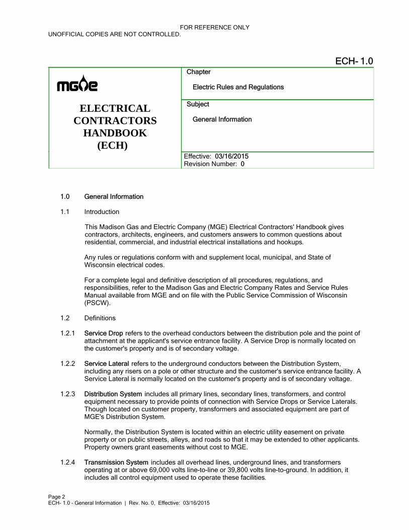
1.0 General Information
1.1 Introduction
This Madison Gas and Electric Company (MGE) Electrical Contractors' Handbook gives contractors, architects, engineers, and customers answers to common questions about residential, commercial, and industrial electrical installations and hookups.
Any rules or regulations conform with and supplement local, municipal, and State of Wisconsin electrical codes.
For a complete legal and definitive description of all procedures, regulations, and responsibilities, refer to the Madison Gas and Electric Company Rates and Service Rules Manual available from MGE and on file with the Public Service Commission of Wisconsin (PSCW).
1.2 Definitions
1.2.1 Service Drop refers to the overhead conductors between the distribution pole and the point of attachment at the applicant's service entrance facility. A Service Drop is normally located on the customer's property and is of secondary voltage.
1.2.2 Service Lateral refers to the underground conductors between the Distribution System, including any risers on a pole or other structure and the customer's service entrance facility. A Service Lateral is normally located on the customer's property and is of secondary voltage.
1.2.3 Distribution System includes all primary lines, secondary lines, transformers, and control equipment necessary to provide points of connection with Service Drops or Service Laterals. Though located on customer property, transformers and associated equipment are part of MGE's Distribution System.
Normally, the Distribution System is located within an electric utility easement on private property or on public streets, alleys, and roads so that it may be extended to other applicants. Property owners grant easements without cost to MGE.
1.2.4 Transmission System includes all overhead lines, underground lines, and transformers operating at or above 69,000 volts line-to-line or 39,800 volts line-to-ground. In addition, it includes all control equipment used to operate these facilities.
FOR REFERENCE ONLYUNOFFICIAL COPIES ARE NOT CONTROLLED.
Page 3ECH- 1.0 - General Information | Rev. No. 0, Effective: 03/16/2015
1.3 Determine Location of Electric Facilities in Area of Proposed Work
Prior to performing any excavation, grading, blasting, construction, erection, or demolition work within MGE's service territory, call Diggers Hotline at 1-800-242-8511 or 811 or visit www.diggershotline.com to obtain the location of our facilities and other participating utility facilities. We will provide facility location prints and field-locating services promptly.
It is necessary for you to place the request 72 hours (three working days) in advance of nonemergency excavation as required in Section 182.0175 of the Wisconsin Statutes. Make an additional request for location of facilities when the project is delayed or interrupted for ten or more workdays or when changes are made in the proposed construction.
You, as the contractor, are responsible for maintaining the stakes and markings placed by our locating personnel who mark the location of our existing facilities. If the markings are inadvertently destroyed or additional work is to be performed which requires re-staking of your project area, call Diggers Hotline at 1-800-242-8511 or 811 again.
When emergency excavation is necessary, call Diggers Hotline at 1-800-242-8511 or 811 during normal working hours. If there is an emergency outside of normal working hours, call 608-252-7111 or 1-800-245-1123. MGE locating personnel will respond promptly and field locate our facilities for you.
An emergency location is defined as an underground locate request where excavating or demolition must begin prior to the standard three business days. An emergency exists only when one or more of the following conditions exists:
The unforeseen excavation which, if not performed, could result in the loss of life or limb.a.The excavation is required to repair a service outage.b.Excavation is required prior to three business days in order to prevent property damage.c.An unstable condition exists which may result in any of the conditions listed above (for d.example, a leak in any service main or a fault in a primary or secondary wire and/or cable).
When calling in an emergency excavation, inform the operator that an emergency situation exists and be prepared to explain which of the above conditions is in effect. The operator will prepare the ticket for immediate transmission and issue a start date equal to the time the excavation is scheduled to commence.
1.3.1 Placement of Facilities Adjacent to Electric Distribution
Facilities being installed to cross existing underground electric distribution wires and/or conduit (operating at less than 39,800 volts to ground) at or near an angle of 90 degrees must maintain a minimum clearance of 6 inches. Contact MGE Engineering for review of the circumstances involved in all these installations.
Facilities that are to be installed parallel or nearly parallel to existing underground electric distribution wires and/or conduit must provide a minimum of 12 inches of horizontal clearance. Unless it is planned to shore the ditch, increase the horizontal clearance 12 inches for each12 inches of depth of ditch below the level of the existing facilities.
Contact MGE Engineering for review of the circumstances involved in all these installations.
Aboveground appurtenances, poles, buildings, etc., placed adjacent to overhead electric facilities must conform to the clearances specified in the Wisconsin Administrative Code which has adopted, with some changes, the National Electric Safety Code and the National
FOR REFERENCE ONLYUNOFFICIAL COPIES ARE NOT CONTROLLED.
Page 4ECH- 1.0 - General Information | Rev. No. 0, Effective: 03/16/2015
Electric Code. If you have any question as to the clearance required, call MGE Engineering.
If you are engineering a project or planning to bid on a project that may jeopardize existing MGE electric facilities, call MGE at 608-252-7373 for assistance in providing relocation costs or coordination of work activities.
1.3.2 Placement of Facilities Adjacent to Electric Transmission
Facilities being installed to cross existing underground electric transmission facilities (operating at 39,800 or more volts to ground) must maintain an 18-inch minimum clearance. Contact MGE Engineering for review of the circumstances involved in all these installations.
Facilities that are going to be installed parallel or nearly parallel to existing underground electric transmission cables or conduit must maintain a minimum horizontal clearance of 18 inches. Unless it is planned to shore the ditch, increase the horizontal clearance 12 inches for each 12 inches of depth of the ditch below the level of the transmission line.
Aboveground appurtenances, poles, buildings, etc., placed adjacent to overhead electric facilities must conform to the clearances specified in the Wisconsin Administrative Code which has adopted the National Electric Safety Code and the National Electric Code. If you have any question as to the clearance required, call MGE Engineering.
If you are engineering a project or planning to bid on a project which may jeopardize existing MGE electric transmission facilities, call MGE at 608-252-5644 for assistance in providing relocation costs or coordination of work activities.
1.3.3 Excavation Near Underground Electric Facilities
After the location of all underground electric facilities has been determined, make sure all machine operators, foremen, and supervisors on the project are aware of their location. Do not forget new people on the job. They will not know the facilities are there unless you tell them.
Excavations crossing or adjacent to electric facilities must conform with all applicable federal, state, and local codes and ordinances.
Use caution when excavating near underground electric facilities to ensure no damage is inflicted to the cable jacketing or concentric neutral wires. Do not use poured concrete within 18 inches of underground electric cables due to the deterioration it causes to the insulation medium on the cables. This deterioration is not immediate but occurs over time. The length of time to cable failure depends on many factors including strength of concrete, water table, and other environmental conditions.
Do not use any power-operated excavating or earth-moving equipment within 18 inches of the underground facility and the cutting edge of the tool. This is covered in Section 182.0175 of the Wisconsin Statutes. If you are within 18 inches of the underground facility, it will be necessary to hand dig around it to prevent damage.
Shoring, sloping, and/or some equivalent means meeting OSHA requirements must be used to prevent caving or movement of ditch banks adjacent to underground electric facilities.
Provide proper supports when excavating near or under electric facilities. These supports are not to damage the facilities they are supporting. If you are uncertain as to what is required, call MGE Engineering.
Do not attempt to bore past an underground electric facility without adequately determining sufficient clearance exists. It is recommended that facilities be exposed as necessary to
FOR REFERENCE ONLYUNOFFICIAL COPIES ARE NOT CONTROLLED.
Page 5ECH- 1.0 - General Information | Rev. No. 0, Effective: 03/16/2015
prevent damage. Note: Even a simple underground electric service is capable of causing severe injury and/or death if handled improperly.
On all excavations adjacent to MGE underground electric transmission facilities, an MGE representative is to be present. Call 608-252-7188 to coordinate this inspection work.
1.3.4 Construction Near Overhead Electric Facilities
After the location of overhead electric facilities has been determined, make sure all machine operators, foremen, and supervisors on the project are aware of their location. Do not consider any overhead wire to be insulated. Do not park tall equipment or create a load/unload area under overhead conductors.
Any time you leave the traveled portion of a road, you must consider that the overhead line clearance may not be sufficient for your tall equipment. Any overhead electric conductor including 120/240-volt service is sufficient to cause severe injury and/or death if contacted.
OSHA requires that you maintain a minimum safety clearance of 10 feet when using backhoe excavators or boom lifts, erecting scaffolding, raising dump boxes on vehicles, and during use of any tall equipment near overhead electric facilities.
Contact the MGE Construction Department if crane operations could get closer than 20 feet to the overhead electric facilities. The crane operator shall comply with OSHA 1926.1408 and 1926.1409 if the crane could get closer than 20 feet to an overhead conductor.
When excavating is to be performed adjacent to overhead poles and/or structures, leave a minimum of 2 feet of ground at the ground line of the pole along with a one-to-one slope from that point to the new grade level. Other arrangements can be made by contacting MGE Construction Engineering.
If you believe any structure, permanent or temporary, will be in conflict or close proximity to overhead conductors or a Service Drop, contact MGE Construction Engineering.
1.3.5 Blasting Near Any Electric Facility
Do not perform blasting operations in the vicinity of any MGE facilities until we have been notified and measured, satisfactory to us, for safe control of the blasting and so that protection of all MGE facilities have been taken. Such measures will include preplanned emergency procedures.
When blasting operations are performed, they shall be done only by a licensed blaster and strictly in accordance with all local, state, and federal codes and regulations. Liability for any damage remains the responsibility of the party performing the blasting.
1.3.6 Backfilling in the Area Near Underground Electric Facilities
Report any scrapes, cuts, abrasions, or broken underground cables and/or conduit that have occurred while the facilities are exposed. Call MGE at 608-252-7111 to report any damage and have the underground facilities inspected prior to backfilling. We will inspect and make necessary repairs as warranted.
Where excavation removes the original ground under concrete conduit and manhole systems, backfill the area below this facility with pit run or washed sand compacted mechanically in 6-inch lifts to provide the same or better support than was there prior to the excavation.
Replace the sand where excavation removes the original thermal sand from around underground transmission facilities. MGE personnel on the site will make the determination
FOR REFERENCE ONLYUNOFFICIAL COPIES ARE NOT CONTROLLED.
Page 6ECH- 1.0 - General Information | Rev. No. 0, Effective: 03/16/2015
on whether the backfill is appropriate.
Compact the backfill above the facilities by mechanical compaction in accordance with MGE specifications.
1.3.7 Grading and Landscaping Work
When grading or landscaping work is planned which involves the lowering of existing grades, determine the depth of the underground facilities in the area by hand excavation under MGE guidance before the work commences. Raising or lowering of underground electric facilities due to grade changes is at the cost of the party changing the grade.
1.4 Certificate of Inspection Required Before Connection
MGE requires a Certificate of Inspection from the authorized electrical inspector of the appropriate town, village, or city before connecting new or modified services.
If the area or facility is not required by law to have an authorized electrical inspector, MGE will accept, in lieu of the Certificate of Inspection, a signed and notarized affidavit from the electrical contractor which certifies the wiring conforms to the Wisconsin State Electrical Code.
1.5 Before Applying for Service Connections
Service connections and extensions are made in accordance with filed rules and regulations. However, MGE recommends that before you apply for service or prepare wiring plans, you give attention to the following:
1.5.1 Contact the MGE Electric Construction Engineering Department as soon as you begin planning for your facility.
1.5.2 Applications
Apply for service as far in advance as possible of the date service is required. You may apply for service at the MGE General Office Facility or at:
http://www.mge.com/images/PDF/Forms/AppNewServiceInstall.pdf.
Provide the date your service is required.
Completely identify property location including name and address and lot and block number, and provide site plans when possible.
For commercial and industrial buildings, MGE needs the architect's and engineer's names and telephone numbers, the type of building, and the planned load.
In areas not served by municipal sewer and water, include a copy of septic and water system prints.
1.5.3 Voltages
Check with MGE about the availability of 120/208-volt or 277/480-volt three-phase, four-wire service.
Check the low-voltage network map (see NET-1 ) to determine if you are served by the underground low-voltage network system which covers the downtown Madison area (see Section A 7).
FOR REFERENCE ONLYUNOFFICIAL COPIES ARE NOT CONTROLLED.
Page 7ECH- 1.0 - General Information | Rev. No. 0, Effective: 03/16/2015
1.5.4 Underground Service
Check or inquire about primary or secondary services.
Review Section 19.16 of the Madison General Ordinances entitled "Underground Utility Entrance Facilities" concerning underground entrance requirements.
1.5.5 Metering
Check if there are proposed metered locations greater than 200 amps. If so, a transformer-rated meter socket is required.
1.5.6 Underground Vaults in the Network Area
Customers with present or prospective loads of 75 KW or more must provide transformer vaults approved by MGE and meet all applicable specifications and governmental codes (see Section A 7).
1.5.7 New Residential or Commercial Developments
Check municipal streetlighting requirements for new plats.
FOR REFERENCE ONLYUNOFFICIAL COPIES ARE NOT CONTROLLED.
Page 8ECH- 2.0 - Character of Service | Rev. No. 0, Effective: 03/16/2015
ECH- 2.0Chapter
Electric Rules and Regulations
ELECTRICAL CONTRACTORS
HANDBOOK(ECH)
Subject
Character of Service
Effective: 03/16/2015 Revision Number: 0
2.0 Character of Service
MGE distributes electric current to residential, commercial, and network customers as follows:
2.1 Residential, Commercial, and Network
Transformers supplied by MGE are typically available at 120/240 and 120/208 volts,277/480 volts, 120/208 (low-voltage network), and 277/480 (spot network). Transformers are standard ratio and standard impedance single- and three-phase oil-cooled types only.
2.2 Residential and Commercial
2.2.1 Single-phase, 60-cycle alternating current is available at 120/240 volts or, in special circumstances, 120/208 volts over a three-wire service.
2.2.2 Customers outside the low-voltage network system who provide us with acceptable space for transformer installations may obtain three-phase 120/208 volts or 277/480 volts over a four-wire service subject to the following minimum 15-minute demand: 120/208 volts, 75 KW; 277/480 volts, 150 KW.
2.3 Commercial Only
2.3.1 Three-phase, 60-cycle alternating current may be supplied at 2,400/4,160 volts for large power installations over a four-wire service. This service is available at limited locations and at MGE's discretion.
2.3.2 Three-phase, 60-cycle alternating current at 7,970/13,800 volts over a four-wire service is available at limited locations and at MGE's discretion.
2.4 Network Only
2.4.1 Sixty- (60) cycle alternating current may be supplied at 120/208 volts over a three-wire or four-wire service.
2.4.2 Three-phase, four-wire, 277/480-volt spot network service is provided only upon MGE's specific written approval where:
The customer requests it,

FOR REFERENCE ONLYUNOFFICIAL COPIES ARE NOT CONTROLLED.
Page 9ECH- 2.0 - Character of Service | Rev. No. 0, Effective: 03/16/2015
The 15-minute demand exceeds 750 KW,
Suitable multiple 13.8-KV circuits are available at the proposed site, and
The customer provides necessary transformer space.
FOR REFERENCE ONLYUNOFFICIAL COPIES ARE NOT CONTROLLED.
Page 10ECH- 3.0 - Service Facilities | Rev. No. 0, Effective: 03/16/2015
ECH- 3.0Chapter
Electric Rules and Regulations
ELECTRICAL CONTRACTORS
HANDBOOK(ECH)
Subject
Service Facilities
Effective: 03/16/2015 Revision Number: 0
3.0 Service Facilities
3.1 Service Entrance Specifications
MGE specifies, in writing, customers' service entrance locations, including service entrance conduit sizes, quantity, and termination points.
3.2 For each customer's building or premise, MGE supplies:
No more than one Service Drop or Service Lateral;
No more than one class of service;
No more than one meter; and
Service to no more than one service entrance, main disconnect, or MGE-approved
metering device.
3.2.1 Exceptions:
When more than one point of delivery is necessary because of voltage regulation,
governmental requirements, or regulatory orders.
When more than one Service Drop or Service Lateral of the same class of service is
necessary to meet the load requirements of large installations.
When row houses and other multiple occupancy buildings comply with the State electrical
code by having areas separated by fire walls.
When an additional service or meter may be required to accommodate special approved
service rates.
Where multiple-occupancy buildings require separate meters for individual tenants, more
than one meter is allowed.
When total load exceeds 800 KW for single-metered commercial customers, two classes
of service are available.
FOR REFERENCE ONLYUNOFFICIAL COPIES ARE NOT CONTROLLED.
Page 11ECH- 4.0 - Overhead Service Drops and Underground Service Laterals (Non-Network) | Rev. No. 0, Effective: 03/16/2015
ECH- 4.0Chapter
Electric Rules and Regulations
ELECTRICAL CONTRACTORS
HANDBOOK(ECH)
Subject
Overhead Service Drops and Underground Service Laterals (Non-Network)
Effective: 03/16/2015 Revision Number: 0
4.0 Overhead Service Drops and Underground Service Laterals (Non-Network)
4.1 Requirements
4.1.1 MGE installs, owns, and maintains all Service Drops and Service Laterals.
4.1.2 For overhead Service Drops, the applicant's service entrance facility must be located at a point readily accessible to the Distribution System and at a height to provide for proper code clearance of the Service Drop wire.
Where it is necessary to cross adjacent property, the applicant must make arrangements with the landowner for MGE to obtain the proper easements.
The applicant must also obtain the proper location for the service head from MGE and provide suitable anchorage for supporting the Service Drop on the building.
4.1.3 If the present or prospective load is 75 KW or more, MGE specifies that the applicant must provide either:
A transformer vault with vehicle access constructed in accordance with all applicable codes.
Space for the installation of self-enclosed, pad-mounted transformers and switchgear with vehicle access and in accordance with Wisconsin State Electrical Code (PSC 114.317).
In high-rise buildings, conduit extensions, space for the installation of transformers, primary cables, and associated switchgear and, upon our request, suitable space on-site outside the building for the installation of high-voltage fused disconnecting equipment.
4.2 Location of Service
All Service Drops and Service Laterals will be extended from the MGE Distribution System to the customer's service entrance facility over the most direct and properly engineered route as determined by MGE. The customer's service entrance point will be specified by MGE.
4.3 Customer Contribution for Service Facilities
Single-phase Service Drops or laterals will be provided up to 120 feet free and three-phase Service Drops or laterals will receive up to 50 feet free. This is measured from the Distribution
FOR REFERENCE ONLYUNOFFICIAL COPIES ARE NOT CONTROLLED.
Page 12ECH- 4.0 - Overhead Service Drops and Underground Service Laterals (Non-Network) | Rev. No. 0, Effective: 03/16/2015
System to the customer's service entrance facility using the most direct and properly engineered route as determined by MGE. The customer will pay an incremental cost per foot for all additional footage to the customer's specified service entrance point. See MIS-10 and MIS-11 for costs and methods for determining these charges.
4.4 Rights-of-Way, Easements, and Maintenance of Grade
The applicant or developer is responsible for furnishing MGE with rights-of-way and easements within reasonable time to meet service requirements. The right-of-way must be cleared of trees, stumps, and other obstructions prior to installation. After installation, the right-of-way may be used by the grantor in any way that does not interfere with MGE's ability to maintain its electrical facilities at any time.
The right-of-way must be graded within 6 inches of final grade and be maintained by the applicant during utility construction. Future changes or relocations of our facilities due to changes in grade will be at the property owner's expense.
FOR REFERENCE ONLYUNOFFICIAL COPIES ARE NOT CONTROLLED.
Page 13ECH- 5.0 - Meters and Meter Equipment | Rev. No. 0, Effective: 03/16/2015
ECH- 5.0Chapter
Electric Rules and Regulations
ELECTRICAL CONTRACTORS
HANDBOOK(ECH)
Subject
Meters and Meter Equipment
Effective: 03/16/2015 Revision Number: 0
5.0 Meters and Meter Equipment
5.1 Customer Responsibility
Customers are responsible for furnishing and installing all wiring for meter installations, including such associated facilities as meter sockets, meter enclosures, meter test block enclosures, current transformer enclosures, etc., as required for the appropriate type of metering installations specified in this section. Meter sockets must be approved by MGE for the particular type of service and comply with local and state codes.
5.2 Access
5.2.1 In outdoor installations, locate meters where access won't promote damage to lawns, gardens, or shrubbery.
5.2.2 Meters must be installed in accessible areas with a minimum of 3 feet of frontal clearance so MGE personnel can read and test them without causing customer inconvenience or a safety hazard to MGE personnel.
5.2.3 For multiple-unit residential, commercial, and industrial customers such as apartments, office buildings, stores, and factories, meters should be located in easily accessible portions of the buildings.
Where there are a number of meters, they must be grouped together and have the sockets marked to indicate the portions of the buildings supplied by each meter.
Where meters are mounted side by side, leave at least a 7-inch space between each meter and the nearest adjacent piece of equipment to permit testing and adjusting. Use of a 6-inch space section may be required to meet this requirement.
5.3 Mounting and Location
5.3.1 Meters mounted inside or outside must be between 4 and 6 feet above final grade. Final grade must be established before the meters can be set.
Exception: Pedestal-type meter sockets and multiple meter stacks must be between 3 and 6 feet above final grade for outside installations.
FOR REFERENCE ONLYUNOFFICIAL COPIES ARE NOT CONTROLLED.
Page 14ECH- 5.0 - Meters and Meter Equipment | Rev. No. 0, Effective: 03/16/2015
Exception: Multiple meter stacks must be between 2 and 6 feet above final grade for inside installations and between 2.5 and 6 feet above final grade for outside installations.
5.3.2 Meters must be located in such a manner as not to interfere with gas piping or gas metering (see MIS-2 to determine minimum clearance required).
5.3.3 Meter mountings must be secure, free of vibrations, and installed plumb.
5.3.4 Meters must be free from unusual temperature and moisture conditions.
5.3.5 All single and two-family residential buildings must have the meter installation in an accessible area outside the structure. Other buildings that are not easily accessible to MGE personnel during normal working hours must also have an outside meter installation.
5.3.6 In areas subject to damage from falling ice or debris, installation of an ice shield is required (see MIS-12 ).
5.4 Removal and Relocation
5.4.1 Only MGE employees may set, remove, or relocate meters.
5.4.2 On jobs where it is necessary to temporarily disconnect or relocate a meter, contact MGE New Construction Services at 608-252-7373 at least two days before the work is to be done.
5.4.3 Where new wiring has been done, inspection permits and/or signed and notarized affidavits are required before MGE will set the meter.
5.4.4 MGE will seal all meter switches, meter sockets, enclosures, and meters at the time of installation. If a seal is broken in the event of an emergency, contact MGE New Construction Services within 48 hours for resealing.
5.5 Residential
Note: In the network area, a switch-fuse-meter sequence is required.
5.5.1 Horn-type bypass or manual sealable lever-operated bypass for self-contained meter sockets with a meter-switch-fuse sequence for:
Single-phase installations of 320 amperes or less (see RES-1 , RES-2 , RES-3 ,
RES-4 , and RES-5 ).
Three-phase installations of 100 amperes or less (see COM-1 ).
Multiple metering installations for two to six units (see RES-7 ). All apartments having
more than six units should contact MGE (see RES-8 ).
5.5.2 Transformer-rated meter sockets and current transformers may require switch-fuse-meter sequence for:
Single-phase installations over 320 amperes of actual load (see RES-6 ).
Three-phase installations over 200 amperes of actual load (see COM-7 ).
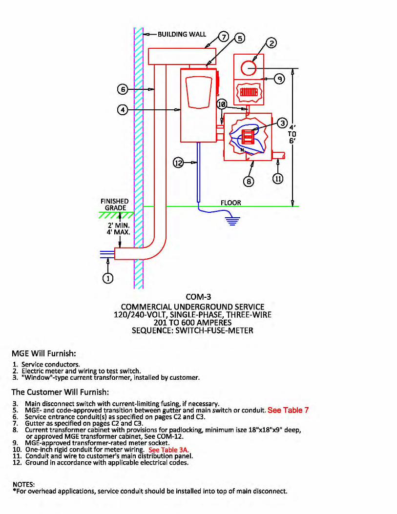
Single-metered and single-phase installations of over 200 amperes for single or
multiple-family residential units (see COM-3 ).
Single-metered and three-phase installations of over 200 amperes for single- or
FOR REFERENCE ONLYUNOFFICIAL COPIES ARE NOT CONTROLLED.
Page 15ECH- 5.0 - Meters and Meter Equipment | Rev. No. 0, Effective: 03/16/2015
multiple-family residential units (see COM-7 ).
5.5.3 Underground Service
For underground service of 200 amperes or less, you must use a meter socket rated for
200 amperes with horn-type or manual sealable lever bypass with meter-switch-fuse sequence (see RES-1 and RES-2 ).
Underground services over 200 amperes must have either:
Current transformer installations with switch-fuse-meter sequenceo(see COM-3 ).Optional 320-ampere meter pedestal (see RES-5 ).oOptional metering transformer cabinets for services from 201 to 600 amperes oand 250 volts or less with single-meter installation and meter-switch-fuse sequence. An outdoor metering transformer cabinet installation is required for residential applications. A main service disconnect must be used ahead of the metering cabinet for use on the AC low-voltage network (see RES-6 ).
5.5.4 Farm Services - Pole Top
Pole-top disconnects of 200 amperes or 400 amperes, single-phase, 120/240-volt with space for a current transformer are permitted. If the option of a standby generator breaker is selected, it must be configured in a break-before-make switch sequence.
The metering sequence will be meter-switch-fuse. For customer-owned generating equipment connections, see Section 12, Customer-Owned Optional Standby Electric Generating Equipment (see MIS-7 and MIS-8 ).
5.5.5 Off-Peak Water Heating Installation
Wiring for residential off-peak water heating installation must include a socket for the off-peak meter. Use a meter-switch-fuse sequence (see RES-9 , RES-9A , and RES-9B ).
5.6 Commercial and Industrial
Note: All services of 460 volts or more must be switch-fuse-meter sequence.
5.6.1 Manual sealable, lever-operated bypass, self-contained heavy-duty jaw-released meter sockets with a meter-switch-fuse sequence for:
Single-phase installations of 100 amperes or less (see COM-1 ).
Three-phase installations of 100 amperes or less (see COM-1 .
5.6.2 Manual sealable, lever-operated bypass, self-contained heavy-duty jaw-released meter sockets with a switch-fuse-meter sequence for:
Single-phase installations for 101 to 200 amperes (see COM-2 ).
Three-phase installations for 101 to 200 amperes (see COM-2 ).
5.6.3 Transformer-rated meter sockets and current transformers with switch-fuse-meter sequence for:
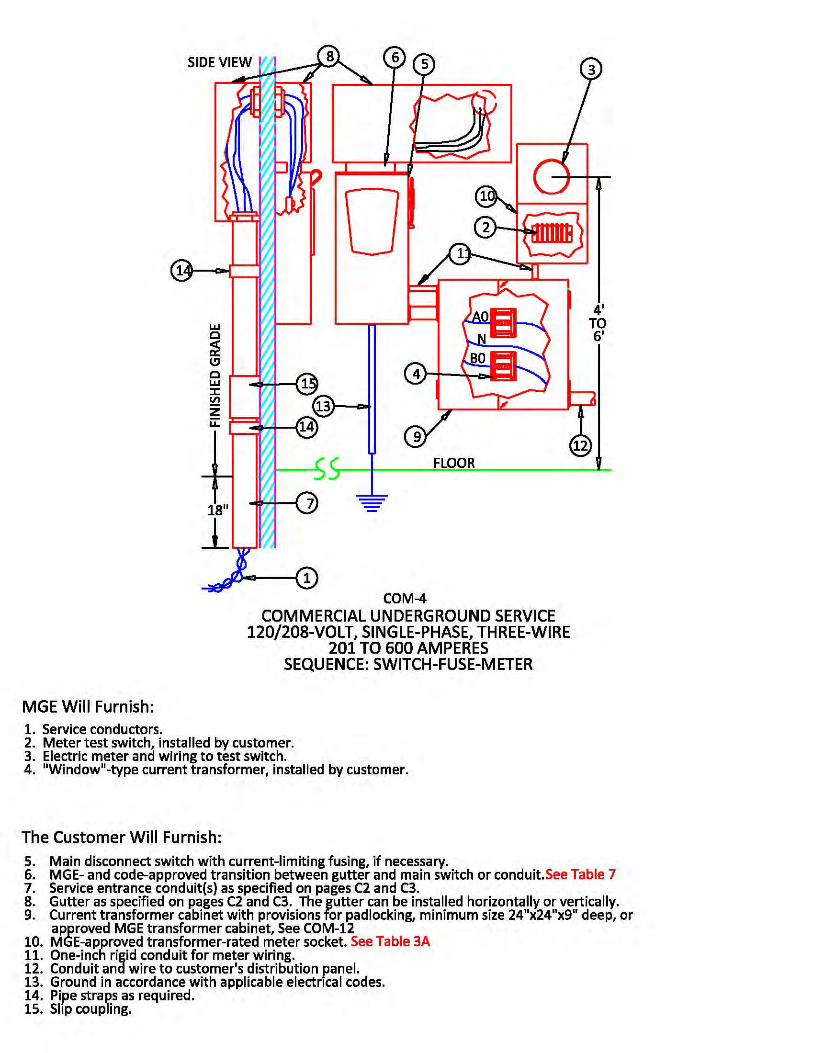
Single-phase installations over 200 amperes for commercial and industrial customers
(see COM-3 and COM-4 ).
FOR REFERENCE ONLYUNOFFICIAL COPIES ARE NOT CONTROLLED.
Page 16ECH- 5.0 - Meters and Meter Equipment | Rev. No. 0, Effective: 03/16/2015
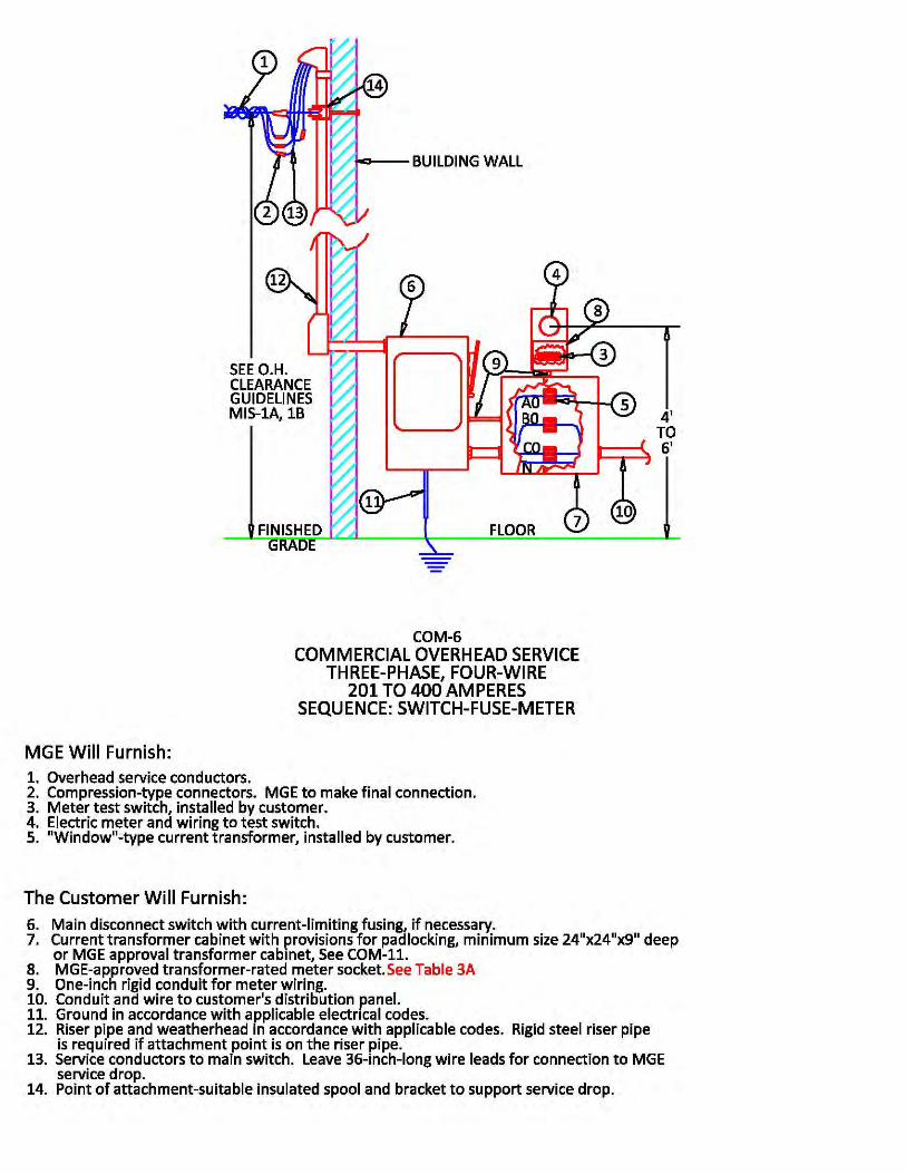
Three-phase installations over 200 amperes for commercial and industrial customers
(see COM-6 , COM-7 , and COM-13 ).
5.6.4 For multiple-meter installations in commercial and industrial buildings, a main building disconnect is required (see COM-8 , COM-9 , and COM-10 ).
5.6.5 Optional metering transformer cabinets for services of 250 volts or less with single-meter installation and meter-switch-fuse sequence. Commercial or industrial single-metered customers with total service capacity of not more than 2,000 amperes may use an indoor or outdoor metering transformer cabinet installation.
The customer must provide an MGE-approved cabinet and install it and associated service entrance equipment in accordance with all applicable codes (see COM-11 and COM-12
). THIS DOES NOT APPLY TO THE AC LOW -VOLTAGE NETWORK AREA.
5.6.6 Three-phase, primary-metered service supplied at 4,160 volts four-wire or 13,800 volts four-wire is available at limited locations and at MGE's discretion. Customers taking service at primary voltage must provide all the necessary switchgear for metering and fused protection of the primary side of the transformers.
A switch-fuse-meter sequence must be used. Drawings of primary metered switchgear must be approved by MGE Construction Engineering prior to purchase (see COM-14 ).
FOR REFERENCE ONLYUNOFFICIAL COPIES ARE NOT CONTROLLED.
Page 17ECH- 6.0 - Non-Network Overhead and Underground Distribution Extensions | Rev. No. 0, Effective: 03/16/2015
ECH- 6.0Chapter
Electric Rules and Regulations
ELECTRICAL CONTRACTORS
HANDBOOK(ECH)
Subject
Non-Network Overhead and Underground Distribution Extensions
Effective: 03/16/2015 Revision Number: 0
6.0 Non-Network Overhead and Underground Distribution Extensions
6.1 To Extend Service
Upon written request, MGE will extend its Distribution System to provide service to new customers in accordance with the following rules and regulations.
6.2 Definition of Distribution System
The Distribution System includes all primary lines, secondary lines, transformers, and control equipment necessary to provide points of connection with Service Drops or Service Laterals. Though located on customer property, transformers and associated equipment are part of MGE's Distribution System.
Normally, the Distribution System is located within an electric utility easement on private property or public streets, alleys, and roads so that it may be extended to other applicants. Property owners grant easements without cost to MGE.
Service voltages supplied by MGE are typically available at 120/240 and 120/208 volts (residential), 120/208 (low-voltage network) and 277/480 (spot network), and all of the above for commercial applications. Transformers are standard ratio and standard impedance single- and three-phase oil-cooled types only.
6.3 MGE's Responsibility
MGE designs and installs the distribution facilities in the most safe, reliable, environmentally accepted manner and at the lowest reasonable cost following accepted engineering and planning practices as determined by MGE.
6.4 Items Included in Costs of Extension
If a service extension is required, the customer may be responsible for the cost. The customer's calculated cost of the required extension (to be paid in advance) will not include individual transformers or increased transformer capacity but will include the cost of:
6.4.1 Extension of primary and secondary facilities (overhead and/or underground), including excavation and restoration.
FOR REFERENCE ONLYUNOFFICIAL COPIES ARE NOT CONTROLLED.
Page 18ECH- 6.0 - Non-Network Overhead and Underground Distribution Extensions | Rev. No. 0, Effective: 03/16/2015
6.4.2 Reconstruction of existing facilities, including changing from single phase to three phase or construction of new feeders made necessary solely by addition of such customers.
6.4.3 Tree trimming and rights-of-way clearing.
6.4.4 Abnormal trenching costs.
6.4.5 Securing easements.
6.4.6 Moving conflicting facilities.
6.4.7 Overtime expenses. Note: For load increases, only the overtime portion of labor applies.
6.4.8 All other costs associated with making the extension, including applicable overheads.
6.5 Definition of Allowances
The average embedded cost for providing a service to an individual customer is used to determine any applicable allowances. MGE determines the average embedded cost allowance (AECA) for the following classes of customers:
6.5.1 Energy-Only Basis
These are generally residential and small commercial customers requesting extensions to serve their facilities on individual lots of multi-lot plats. MGE calculates its average embedded cost of the distribution facilities by dividing the overall depreciated embedded cost by the total number of customers billed in that classification.
6.5.2 Demand and Energy Basis
These are generally commercial customers with demand greater than 20 KW. Their average embedded cost on a per-kilowatt-of-demand basis is calculated by dividing the overall depreciated embedded cost by the total kilowatt demand for this customer class.
6.5.3 Streetlighting Facilities
The average embedded costs are determined on a per-fixture basis by dividing the overall depreciated embedded cost by the total number of fixtures involved.
6.6 Allowances
MGE recomputes and files the AECA annually on March 1. For current information, call MGE Construction Engineering.
6.7 Application of Allowances
MGE applies the allowances to each class of customer as follows:
6.7.1 Energy-Only Customers
The requesting customer receives allowances only for lots having structures beyond the foundation stage that take a Service Drop or Service Lateral directly from the distribution extension being made.
The customer pays the total cost of the extension as previously described, less the average embedded cost per customer multiplied by the number of customers to be served by the extension. The cost is computed on an estimated basis, and the requesting customer makes
FOR REFERENCE ONLYUNOFFICIAL COPIES ARE NOT CONTROLLED.
Page 19ECH- 6.0 - Non-Network Overhead and Underground Distribution Extensions | Rev. No. 0, Effective: 03/16/2015
an advance deposit in that amount.
Refunds, on an average embedded-cost-per-customer basis, are made to the original customer who made the deposit as new customers take Service Drops or Service Laterals within five years of the original extension completion. The refund equals whichever is greater - the AECA in effect at the time the contributed extension was installed or the AECA in effect at the time the meter was set.
In either case, MGE reduces the refund by its costs incurred designing and installing the distribution facilities for the second customer. The total refund never exceeds the original total amount paid, and no interest is paid on refunds.
MGE sends a contract letter specifying the terms and conditions for any refunds to the original contributor.
6.7.2 Demand Plus Energy Customers
Customers requesting service that requires rearrangement of or new distribution facilities pay in advance the total cost of the rearrangement or new extension, less the AECA per KW of demand multiplied by the customer's estimated average billed demand. The cost is estimated, and a deposit equal to the estimate is made in advance.
Upon completion of the work, the project is reviewed to determine whether it is within the original scope. If the project is out of scope, an appropriate refund or additional bill will be submitted to the original contributor.
The customer's estimated average billed demand is determined by using 40 percent of the customer's stated service entrance facility rating. It is based on MGE's experience with the relationship between a customer's actual load and the size of the service entrance.
For customers requesting an increase in facilities, the cost is the total distribution facility construction cost as defined in Section 6.4, less an allowance equal to the incremental increase in demand multiplied by the average embedded-cost-per-KW, less the accumulated depreciation of the removed facilities, less the salvage value of the facilities removed.
The cost is estimated, and the customer makes a contribution equal to that estimate in advance. Upon completion of the work, the project is reviewed to determine whether it is within the original scope. If the project is out of scope, an appropriate refund or additional bill will be submitted to the original contributor.
After a deposit has been received, MGE will send a contract letter specifying the possibility of refunds to the customer. It explains the circumstances under which refunds may occur as a result of the addition of new customers taking Service Drops or Service Laterals off the extension within five years of the completion of the original extension.
The refund equals the greater of the AECA in effect at the time the contributed extension was installed or the AECA in effect at the time the meter was set. In either case, MGE reduces the refund by its costs to design and install the distribution facilities for the second customer. The total refund never exceeds the original total amount paid, and no interest is paid on refunds.
6.7.3 Streetlight Extensions
For streetlight extensions, Service Drops, or Service Laterals, the cost to the requesting party is the total cost of the facilities needed to provide service to the streetlights, less the AECA per fixture. MGE collects this cost in advance on an estimated basis.
Final appropriate refunds or additional bills are submitted to the original contributor upon
FOR REFERENCE ONLYUNOFFICIAL COPIES ARE NOT CONTROLLED.
Page 20ECH- 6.0 - Non-Network Overhead and Underground Distribution Extensions | Rev. No. 0, Effective: 03/16/2015
completion of the installation. MGE treats each request for service and/or extension individually for payment.
6.7.4 More Than One Rate Class
For extensions to more than one customer where some are billed on energy only and some on demand and energy, MGE determines the total allowance by either allocating certain costs of the extension to each class separately or by adding the allowances together to derive one total allowance to offset one total cost. MGE chooses the method that minimizes confusion over payment and/or refund policies.
6.8 Upgrade of Distribution Facilities
For customers who require distribution facility upgrades, MGE determines allowances as follows:
6.8.1 Demand Schedule
Customers served under a demand rate schedule receive an embedded cost allowance. The KW of demand used in computing the allowance is the customer's estimated average billed demand after the upgrade, less the customer's estimated average billed demand before the upgrade.
6.8.2 Customers Transferring to a Different Energy-Only Subclassification
If a customer changes energy-only subclassifications after the upgrade, the customer receives an allowance equal to the difference between the two average embedded cost allowances.
6.8.3 Customers Transferring to a Demand Classification
If a customer transfers from an energy only to a demand plus energy classification after the upgrade, the customer receives an AECA. The KWs of demand to be used in determining the allowance is the customer's estimated average billed demand after the upgrade, less an estimate of the customer's prior average billed demand (based on calculations described in Sections 6.7.1 and 6.7.2).
6.9 Relocation and Rebuilding of Existing Facilities
Submit a written request to relocate service and distribution facilities at the customer's expense, including replacement of overhead with underground.
MGE computes the estimate by calculating the total cost of the proposed work, including applicable overheads and incidental charges, less the accumulated depreciation of the removed facilities, less their salvage value. The cost is estimated, and a contribution equal to the estimate is made in advance.
MGE refunds the contribution as additional customers attach to the facilities unless the additional customers require a new extension. The refund will be equal to the greater of the AECA in effect at the time the contributed extension was installed or the AECA in effect at the time the meter was set.

FOR REFERENCE ONLYUNOFFICIAL COPIES ARE NOT CONTROLLED.
Page 21ECH- 6.0 - Non-Network Overhead and Underground Distribution Extensions | Rev. No. 0, Effective: 03/16/2015
In either case, this refund is reduced by MGE's costs incurred designing and installing the distribution facilities for the second customer. Refunds are made for up to five years after the completion of the changes to the facilities. The total refund never exceed the original total amount paid and no interest is paid on refunds.
FOR REFERENCE ONLYUNOFFICIAL COPIES ARE NOT CONTROLLED.
Page 22ECH- 7.0 - Low-Voltage AC Network System | Rev. No. 0, Effective: 03/16/2015
ECH- 7.0Chapter
Electric Rules and Regulations
ELECTRICAL CONTRACTORS
HANDBOOK(ECH)
Subject
Low-Voltage AC Network System
Effective: 03/16/2015 Revision Number: 0
7.0 Low-Voltage AC Network System (see NET-1 )
7.1 Definitions
7.1.1 A Service Lateral in the network system is defined as the underground secondary facilities between the nearest splicing point on the underground low-voltage network system and the supply end of the customer's service entrance facilities. The Service Laterals are installed in conduit and normally are only to serve loads that are less than 75 KW.
7.1.2 The low-voltage network Distribution System includes primary lines, ducts, manholes, conduits, transformers, and all other facilities that are part of the system. Some of these facilities may be located on the customer's premises.
7.2 Payment for Service Laterals
The customer will pay in advance $5 per foot for that part of the Service Lateral as defined above that is located between that customer's lot line and service entrance facilities.
7.3 Network Residential Metering
7.3.1 Horn-type bypass or manual-sealable lever-operated bypass for self-contained meter sockets with a switch-fuse-meter sequence for:
Single-phase installations of 200 amperes or less (see NET-2 ).
Three-phase installations of 200 amperes or less (see NET-2 ).
Multiple-metering installations for two to six units (see NET-3 ). All apartments having
more than six units should contact MGE (see NET-5 ).
7.3.2 Transformer-rated meter sockets and current transformers with switch-fuse-meter sequence for:
Single-phase installations over 200 amperes (see NET-7 ).
Three-phase installations over 200 amperes (see NET-6 ).
7.4 Network Commercial and Industrial Metering
FOR REFERENCE ONLYUNOFFICIAL COPIES ARE NOT CONTROLLED.
Page 23ECH- 7.0 - Low-Voltage AC Network System | Rev. No. 0, Effective: 03/16/2015
7.4.1 Manual-sealable lever-operated bypass self-contained heavy-duty jaw-released meter sockets with a switch-fuse-meter sequence for:
Single-phase installations of 200 amperes or less (see NET-2 ).
Three-phase installations of 200 amperes or less (see NET-2 ).
7.4.2 Transformer-rated meter sockets and current transformers with switch-fuse-meter sequence for:
Single-phase installations over 200 amperes for commercial and industrial customers
(see NET-7 ).
Three-phase installations over 200 amperes for commercial and industrial customers
(see NET-6 ).
7.4.3 For multiple-meter installations in large commercial and industrial buildings, a main building disconnect is required (see NET-4 and NET-5 ).
7.5 Transformer Vaults
If the present or prospective load is 75 KW or more, MGE specifies the applicant must provide either:
A transformer vault with vehicle access constructed in accordance with all applicable codes with a minimum 16' D x 18' W x 10' H with two 32" x 32" clear manways and a 6' x 8' equipment-way opening for access and 3 square inches of free air ventilation per KVA of transformer capacity (see MIS-3 ).
In high-rise buildings, conduit extensions, space for the installation of transformers, primary cables, and associated switchgear and, upon MGE's request, suitable space on-site outside the building for the installation of high-voltage fused disconnecting equipment.
Upon customer request, MGE will furnish transformer vault plans and specifications, including space and ventilation requirements, but the customer's architects and engineers must be responsible for structural design. Such plans must be submitted to MGE prior to construction.
7.6 New Buildings
New building construction for which Service Laterals are provided must include MGE-approved wall openings for service ducts at locations MGE specifies.
FOR REFERENCE ONLYUNOFFICIAL COPIES ARE NOT CONTROLLED.
Page 24ECH- 8.0 - Rights and Responsibilities | Rev. No. 0, Effective: 03/16/2015
ECH- 8.0Chapter
Electric Rules and Regulations
ELECTRICAL CONTRACTORS
HANDBOOK(ECH)
Subject
Rights and Responsibilities
Effective: 03/16/2015 Revision Number: 0
8.0 Rights and Responsibilities
8.1 Continuity of Service
MGE uses reasonable diligence to provide an uninterrupted and regular supply of service. MGE is not liable for any interruptions, deficiencies, or imperfections of service. MGE may temporarily suspend the delivery of service when necessary for the purpose of making repairs, changes, and improvements upon any part of the system.
8.2 Balanced Load
The customer is responsible to balance load over the phases as equally as commercial practice will permit and maintain this balance over time.
8.3 Superposition of Electric Energy on Utility System
Where the customer's equipment couples electric energy to their electric system for equipment control, carrier current transmission, signal systems, broadcasting, communication, or any other purpose, the customer shall install equipment suitable to prevent this energy from being imposed upon or entering MGE's electric system.
8.4 Losses Due to Service Disconnection
MGE is not liable for any losses, injuries, or damages to persons or property due to disconnection of service in accordance with the disconnection rule found on page E71 of the Rules and Regulations on file with the PSCW.
8.5 Customer's Responsibility for Damage to MGE Equipment
The customer is responsible for all damage to MGE facilities or equipment caused by the customer or his permittees, including compensation for consumed energy not recorded on the meter.
8.6 Access to Customer Premises
MGE's authorized agents will have access to customer premises at all reasonable times for the purpose of reading meters, making repairs, inspections, investigations, removing MGE property, or any other purpose incident to providing service.
FOR REFERENCE ONLYUNOFFICIAL COPIES ARE NOT CONTROLLED.
Page 25ECH- 8.0 - Rights and Responsibilities | Rev. No. 0, Effective: 03/16/2015
8.7 Abnormal Trenching Costs
The applicant shall pay in advance an amount equal to the estimated extra cost of trenching and hand digging through any area where normal plowing and trenching methods cannot be used; e.g., ledge rock, boulders, landfill, trees, heavy underbrush, watercourses, etc.
Winter charges will apply for any service and/or distribution extension installed between December 1 and March 31 unless the application for service and/or request for distribution extension is received prior to November 1 and the premise and/or site is ready for installation prior to December 1.
The premise and/or site is ready for installation when the following items are satisfied:
All applicable service sketches and easements signed by the customer/owner and a.received by MGE.All applicable deposits received by MGE.b.The entire trench route cleared and graded to within 6 inches of final grade.c.A physical electric service entrance location installed on or in the building. This can d.consist of a pedestal, transocket, and a minimum of the required service entrance conduits stubbed out from the foundation wall or securely mounted on the building.
Note: A mark showing the proposed service location on the foundation or building does not qualify as ready for installation.
8.8 Installations Under and Through Private Paved and Landscaped Areas
Except for damage caused by MGE's negligence, MGE is not liable for damage to trees, shrubs, fences, sidewalks, or other obstructions incident to the installation, repair, or maintenance of its electric facilities. The applicant is responsible for lawn and landscape restoration except as noted above.
If MGE is requested to provide additional landscaping or other services, the applicant is responsible for associated costs. Excavation and backfilling are MGE's responsibility. The backfill will consist of the original soil when possible.
8.9 Installation of Facilities
The character, location, and method of installation of MGE-constructed facilities will be at MGE's discretion and conform to specifications MGE prepares. Any exceptions MGE consents to will be at the customer's expense.
8.10 Applicability of Governmental Codes
All facilities installed, whether by the customer or MGE, will comply with the appropriate provisions of the applicable governmental codes.
8.11 Extraordinary Investment
If an investment in an extension appears extraordinary to MGE, or where extensive enlargement or changes to existing distribution or other facilities required to accommodate the customer do not appear to be economically justified, MGE may require the customer to pay us that portion of the capital expenditure not economically justified by the anticipated annual revenue. Such payments will be made before construction.

FOR REFERENCE ONLYUNOFFICIAL COPIES ARE NOT CONTROLLED.
Page 26ECH- 8.0 - Rights and Responsibilities | Rev. No. 0, Effective: 03/16/2015
In addition, MGE may require a specific contract with the customer to pay operating and maintenance expenses.
FOR REFERENCE ONLYUNOFFICIAL COPIES ARE NOT CONTROLLED.
Page 27ECH- 9.0 - Motors and Starting Requirements | Rev. No. 0, Effective: 03/16/2015
ECH- 9.0Chapter
Electric Rules and Regulations
ELECTRICAL CONTRACTORS
HANDBOOK(ECH)
Subject
Motors and Starting Requirements
Effective: 03/16/2015 Revision Number: 0
9.0 Motors and Starting Requirements
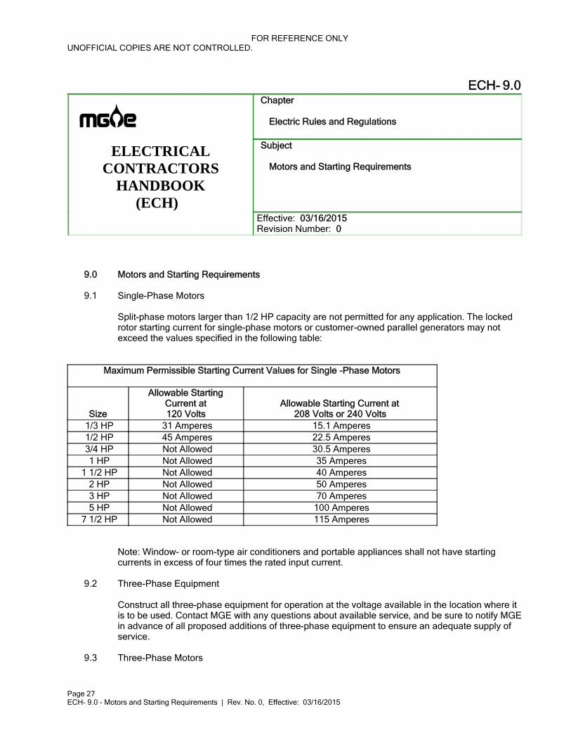
9.1 Single-Phase Motors
Split-phase motors larger than 1/2 HP capacity are not permitted for any application. The locked rotor starting current for single-phase motors or customer-owned parallel generators may not exceed the values specified in the following table:
Maximum Permissible Starting Current Values for Single -Phase Motors
Size
Allowable StartingCurrent at120 Volts
Allowable Starting Current at208 Volts or 240 Volts
1/3 HP 31 Amperes 15.1 Amperes 1/2 HP 45 Amperes 22.5 Amperes 3/4 HP Not Allowed 30.5 Amperes 1 HP Not Allowed 35 Amperes
1 1/2 HP Not Allowed 40 Amperes 2 HP Not Allowed 50 Amperes 3 HP Not Allowed 70 Amperes 5 HP Not Allowed 100 Amperes
7 1/2 HP Not Allowed 115 Amperes
Note: Window- or room-type air conditioners and portable appliances shall not have starting currents in excess of four times the rated input current.
9.2 Three-Phase Equipment
Construct all three-phase equipment for operation at the voltage available in the location where it is to be used. Contact MGE with any questions about available service, and be sure to notify MGE in advance of all proposed additions of three-phase equipment to ensure an adequate supply of service.
9.3 Three-Phase Motors
FOR REFERENCE ONLYUNOFFICIAL COPIES ARE NOT CONTROLLED.
Page 28ECH- 9.0 - Motors and Starting Requirements | Rev. No. 0, Effective: 03/16/2015
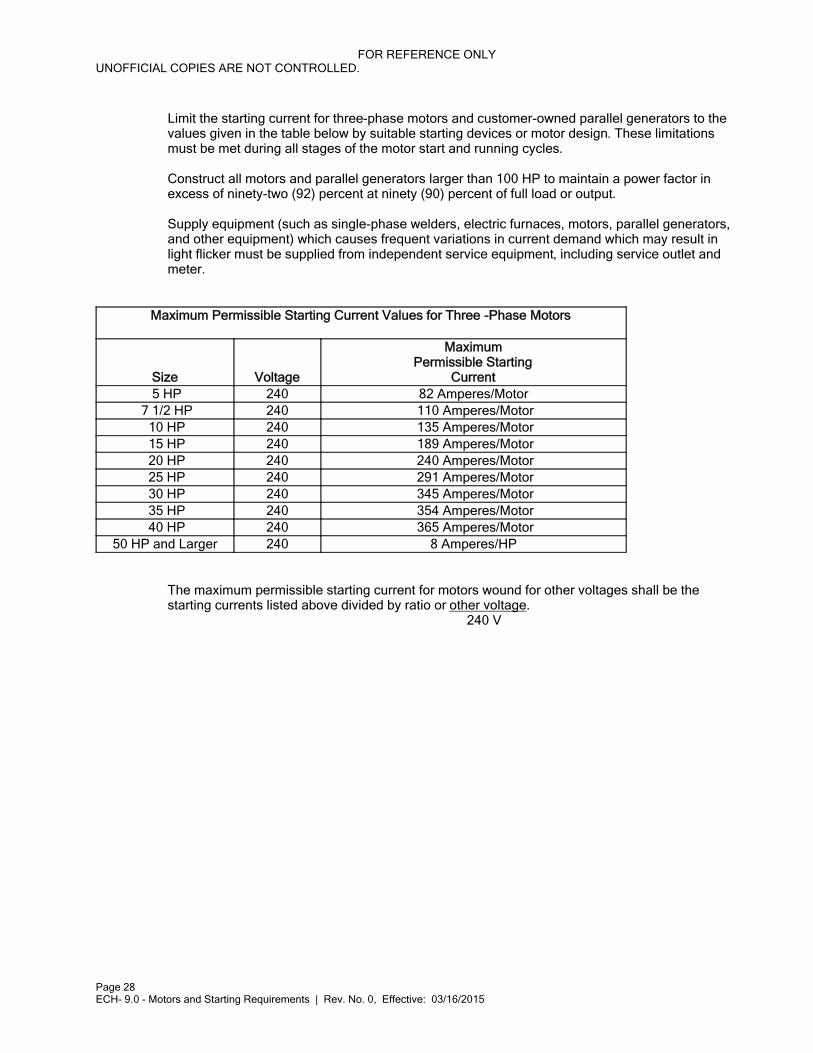
Limit the starting current for three-phase motors and customer-owned parallel generators to the values given in the table below by suitable starting devices or motor design. These limitations must be met during all stages of the motor start and running cycles.
Construct all motors and parallel generators larger than 100 HP to maintain a power factor in excess of ninety-two (92) percent at ninety (90) percent of full load or output.
Supply equipment (such as single-phase welders, electric furnaces, motors, parallel generators, and other equipment) which causes frequent variations in current demand which may result in light flicker must be supplied from independent service equipment, including service outlet and meter.
Maximum Permissible Starting Current Values for Three -Phase Motors
Size Voltage
MaximumPermissible Starting
Current 5 HP 240 82 Amperes/Motor
7 1/2 HP 240 110 Amperes/Motor 10 HP 240 135 Amperes/Motor 15 HP 240 189 Amperes/Motor 20 HP 240 240 Amperes/Motor 25 HP 240 291 Amperes/Motor 30 HP 240 345 Amperes/Motor 35 HP 240 354 Amperes/Motor 40 HP 240 365 Amperes/Motor
50 HP and Larger 240 8 Amperes/HP
The maximum permissible starting current for motors wound for other voltages shall be the starting currents listed above divided by ratio or other voltage.
240 V
FOR REFERENCE ONLYUNOFFICIAL COPIES ARE NOT CONTROLLED.
Page 29ECH- 10.0 - Power Factor Correction Rule | Rev. No. 0, Effective: 03/16/2015
ECH- 10.0Chapter
Electric Rules and Regulations
ELECTRICAL CONTRACTORS
HANDBOOK(ECH)
Subject
Power Factor Correction Rule
Effective: 03/16/2015 Revision Number: 0
10.0 Power Factor Correction Rule
For non-incandescent lighting, the customer is responsible to maintain a power factor to a level of at least:
Ninety (90) percent lagging for illumination or decorative purposes.
Eighty-five (85) percent lagging for advertising purposes, except that no correction is required for any complete sign supplied from a single auxiliary transformer rated at 225 volt amperes or less.
Commercial and industrial customers must maintain a power factor on peak of not less than eighty-five (85) percent or be subject to a penalty as dictated by filed rates.
The power factor is determined by the wattmeter-voltmeter-ammeter method.
FOR REFERENCE ONLYUNOFFICIAL COPIES ARE NOT CONTROLLED.
Page 30ECH- 11.0 - Emergency Electric Service | Rev. No. 0, Effective: 03/16/2015
ECH- 11.0Chapter
Electric Rules and Regulations
ELECTRICAL CONTRACTORS
HANDBOOK(ECH)
Subject
Emergency Electric Service
Effective: 03/16/2015 Revision Number: 0
11.0 Emergency Electric Service
In commercial or network installations where code requires an emergency service connection on the line side of the building main disconnect (as with emergency lighting or fire pumps), MGE will provide a separate service for this. Metering must be according to MGE-approved metering guidelines.
FOR REFERENCE ONLYUNOFFICIAL COPIES ARE NOT CONTROLLED.
Page 31ECH- 12.0 - Customer-Owned Optional Standby Electric Generating Equipment | Rev. No. 0, Effective: 03/16/2015
ECH- 12.0Chapter
Electric Rules and Regulations
ELECTRICAL CONTRACTORS
HANDBOOK(ECH)
Subject
Customer-Owned Optional Standby Electric Generating Equipment
Effective: 03/16/2015 Revision Number: 0
12.0 Customer-Owned Optional Standby Electric Generating Equipment
The purpose of optional standby electric generating equipment is to provide an alternate source of electric power for farms and commercial facilities during power outages to minimize inconvenience or product damage. A standby generator must be connected to the customer's electric system through an approved double-throw break-before-make disconnect switch (see MIS-8 and MIS-9 ). This system will be electrically and mechanically interconnected so the customer's generation cannot feed back into MGE's system.
FOR REFERENCE ONLYUNOFFICIAL COPIES ARE NOT CONTROLLED.
Page 32ECH- 13.0 - Customer-Owned Parallel Electric Generating Equipment | Rev. No. 0, Effective: 03/16/2015
ECH- 13.0Chapter
Electric Rules and Regulations
ELECTRICAL CONTRACTORS
HANDBOOK(ECH)
Subject
Customer-Owned Parallel Electric Generating Equipment
Effective: 03/16/2015 Revision Number: 0
13.0 Customer-Owned Parallel Electric Generating Equipment
13.1 Application and Contract
Before interconnecting a generating system with the MGE system, MGE must receive and approve an application and a contract specifying technical connection and operating aspects for the parallel generating facility. MGE will follow the guidelines of PSC 119 for this review.
13.2 Lockable Load Break Disconnect Switch
MGE requires a lockable load break disconnect switch between generators and the MGE system. A fused cutout switch may be substituted in installations interconnected at greater than 600 volts. Switches must be accessible so MGE can isolate the generating facility from the MGE system when necessary.
13.3 Separate Distribution Transformers
MGE requires separate distribution transformers for generating facilities which may threaten safety or interfere with other customers' services. This should not be necessary for induction-type generators with capacities of 5 KW or less or generating units of 10 KW or less which utilize line-commutated inverters. Ordinarily, single-phase generators should be limited to a capacity of 10 KW or less.
13.4 Automatic Isolation
Each generating facility must have a system for automatically isolating the generator upon loss of the MGE supply, unless MGE wants local generation to supply isolated load. For synchronous and induction generators, this protection ordinarily consists of overcurrent protection, fuse or circuit breaker, plus a voltage- or frequency-controlled contactor to automatically disconnect the unit whenever its output voltage or frequency drifts outside predetermined limits, such as plus or minus ten (10) percent of the rated values. Other suitable protective systems may be accepted.
13.5 Disconnection Upon Request
Customers must disconnect the parallel generation upon request. MGE may isolate the generating facility:
FOR REFERENCE ONLYUNOFFICIAL COPIES ARE NOT CONTROLLED.
Page 33ECH- 13.0 - Customer-Owned Parallel Electric Generating Equipment | Rev. No. 0, Effective: 03/16/2015
For maintenance or repair of MGE facilities.
During system emergencies.
When the generating facility is operating in a hazardous manner or affects service to
other customers or nearby communication systems or circuits.
13.6 Access
Generating facilities must be accessible to MGE personnel at reasonable times for testing isolation and protection equipment, evaluating power quality, and isolating sources of electric service or communication systems problems.
13.7 Rights and Responsibilities
The owner of a generating facility is responsible for protecting owner-installed equipment and adherence to all applicable codes. Certain generating equipment, such as that utilizing line-commutated inverters, sometimes requires an isolation transformer.
A generating facility's power output must be compatible with normal electrical service and not cause that service to fall outside the prescribed limits of PSCW rules and other standard limitations.
A generating facility must not affect the service or equipment of other customers or produce undesirable levels of harmonics in the MGE power supply.
The owner of a generating facility that is or proposes to be interconnected with the MGE system may appeal to the PSCW if any of MGE's requirements are considered excessive or unreasonable. Such an appeal will be reviewed and the customer notified of the PSCW's determination.
FOR REFERENCE ONLYUNOFFICIAL COPIES ARE NOT CONTROLLED.
Page 34ECH- 14.0 - Charges for Overhead Drops and Underground Service Laterals | Rev. No. 0, Effective: 03/16/2015
ECH- 14.0Chapter
Electric Rules and Regulations
ELECTRICAL CONTRACTORS
HANDBOOK(ECH)
Subject
Charges for Overhead Drops and Underground Service Laterals
Effective: 03/16/2015 Revision Number: 0
14.0 Charges for Overhead Drops and Underground Service Laterals
14.1 Temporary Service
MGE will charge $72 for providing a 120/240-volt, single-phase temporary service up to 100 amperes for construction purposes at a location selected by MGE where facilities currently exist. The service head must be located on a satisfactory temporary support provided by the applicant. This support must be located so that wires will not have to be spliced when moved to the permanent location and provide the clearance required by state code (see MIS-5 and MIS-6 ).
For any other location, voltage, or load selected by the applicant, the estimated cost of installing and removing the distribution facilities for temporary service will be paid in advance by the applicant. All temporaries which are larger than 100 amperes or are greater than 277 volts will follow MGE's commercial service rules.
14.2 Permanent Service
No charge will be made for permanent overhead Service Drops and underground Service Laterals meeting the aforementioned definitions and all MGE rules and applicable codes unless there is extraordinary investment or abnormal trenching costs. The customer will pay the portion of the extraordinary investment and abnormal trenching above the cost of a normal service as determined by MGE.
14.3 Upgrade of Service Facilities
No charge will be made for upgrading a Service Drop or Lateral with a larger Service Drop or Lateral.
MGE will require a contribution from a customer requesting to have an overhead Service Drop upgraded to an underground Service Lateral. The contribution will be equal to the cost of the underground Service Lateral, less the cost of an equivalent overhead Service Drop.

FOR REFERENCE ONLYUNOFFICIAL COPIES ARE NOT CONTROLLED.
Page 35ECH- 14.0 - Charges for Overhead Drops and Underground Service Laterals | Rev. No. 0, Effective: 03/16/2015
However, if the change is a result of a substantial increase in consumption or extensive building modifications, then the change will be treated as a request from a new customer for the purpose of calculating the contribution.
FOR REFERENCE ONLYUNOFFICIAL COPIES ARE NOT CONTROLLED.
Page 36ECH- 15.0 - MGE Electric Distribution Engineering Department Directory | Rev. No. 1, Effective: 02/11/2016
ECH- 15.0Chapter
Electric Rules and Regulations
ELECTRICAL CONTRACTORS
HANDBOOK(ECH)
Subject
MGE Electric Distribution Engineering Department Directory
Effective: 02/11/2016 Revision Number: 1
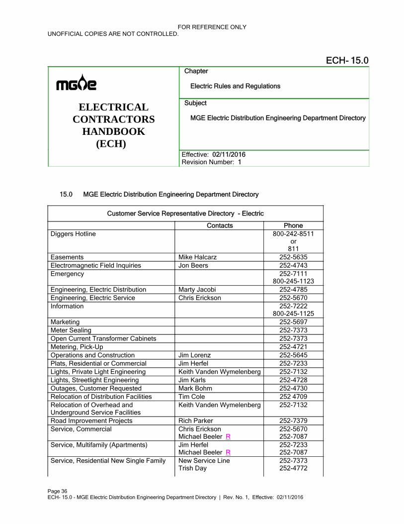
15.0 MGE Electric Distribution Engineering Department Directory
Customer Service Representative Directory - Electric
Contacts PhoneDiggers Hotline 800-242-8511
or811
Easements Mike Halcarz 252-5635Electromagnetic Field Inquiries Jon Beers 252-4743Emergency 252-7111
800-245-1123Engineering, Electric Distribution Marty Jacobi 252-4785Engineering, Electric Service Chris Erickson 252-5670Information 252-7222
800-245-1125Marketing 252-5697Meter Sealing 252-7373Open Current Transformer Cabinets 252-7373Metering, Pick-Up 252-4721Operations and Construction Jim Lorenz 252-5645Plats, Residential or Commercial Jim Herfel 252-7233Lights, Private Light Engineering Keith Vanden Wymelenberg 252-7132Lights, Streetlight Engineering Jim Karls 252-4728Outages, Customer Requested Mark Bohm 252-4730Relocation of Distribution Facilities Tim Cole 252 4709Relocation of Overhead andUnderground Service Facilities
Keith Vanden Wymelenberg 252-7132
Road Improvement Projects Rich Parker 252-7379Service, Commercial Chris Erickson
Michael Beeler R252-5670252-7087
Service, Multifamily (Apartments) Jim HerfelMichael Beeler R
252-7233252-7087
Service, Residential New Single Family New Service LineTrish Day
252-7373252-4772
FOR REFERENCE ONLYUNOFFICIAL COPIES ARE NOT CONTROLLED.
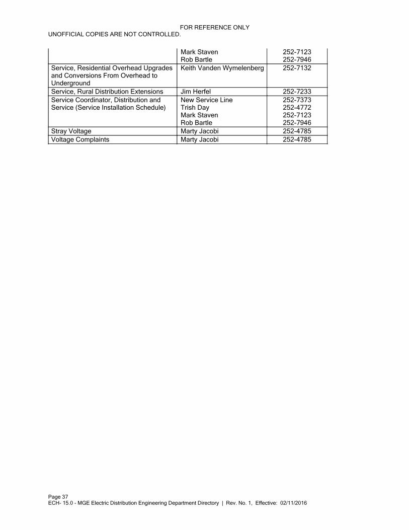
Page 37ECH- 15.0 - MGE Electric Distribution Engineering Department Directory | Rev. No. 1, Effective: 02/11/2016
Mark StavenRob Bartle
252-7123252-7946
Service, Residential Overhead Upgrades and Conversions From Overhead to Underground
Keith Vanden Wymelenberg 252-7132
Service, Rural Distribution Extensions Jim Herfel 252-7233Service Coordinator, Distribution and Service (Service Installation Schedule)
New Service LineTrish DayMark StavenRob Bartle
252-7373252-4772252-7123252-7946
Stray Voltage Marty Jacobi 252-4785Voltage Complaints Marty Jacobi 252-4785
FOR REFERENCE ONLYUNOFFICIAL COPIES ARE NOT CONTROLLED.
Page 38ECH- 16.0 - Service Details | Rev. No. 0, Effective: 03/16/2015
ECH- 16.0Chapter
Electric Rules and Regulations
ELECTRICAL CONTRACTORS
HANDBOOK(ECH)
Subject
Service Details
Effective: 03/16/2015 Revision Number: 0
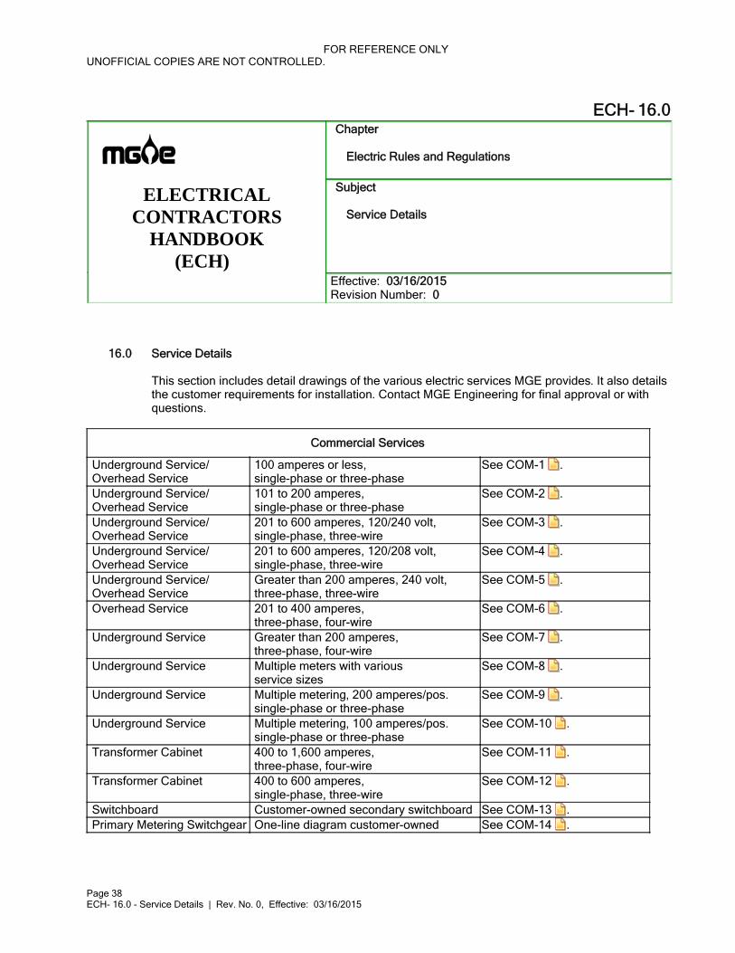
16.0 Service Details
This section includes detail drawings of the various electric services MGE provides. It also details the customer requirements for installation. Contact MGE Engineering for final approval or with questions.
Commercial Services
Underground Service/Overhead Service
100 amperes or less,single-phase or three-phase
See COM-1 .
Underground Service/Overhead Service
101 to 200 amperes,single-phase or three-phase
See COM-2 .
Underground Service/Overhead Service
201 to 600 amperes, 120/240 volt,single-phase, three-wire
See COM-3 .
Underground Service/Overhead Service
201 to 600 amperes, 120/208 volt,single-phase, three-wire
See COM-4 .
Underground Service/Overhead Service
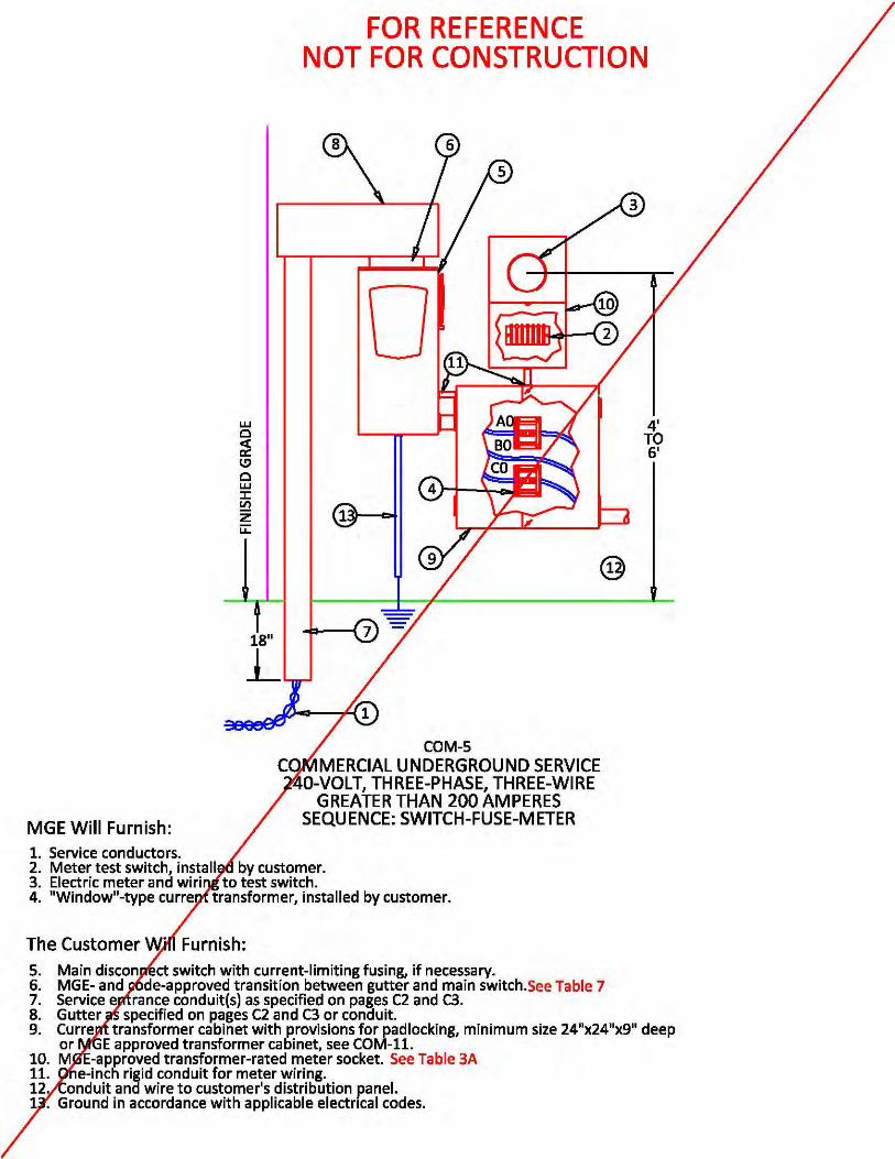
Greater than 200 amperes, 240 volt,three-phase, three-wire
See COM-5 .
Overhead Service 201 to 400 amperes,three-phase, four-wire
See COM-6 .
Underground Service Greater than 200 amperes,three-phase, four-wire
See COM-7 .
Underground Service Multiple meters with variousservice sizes
See COM-8 .
Underground Service Multiple metering, 200 amperes/pos.single-phase or three-phase
See COM-9 .
Underground Service Multiple metering, 100 amperes/pos.single-phase or three-phase
See COM-10 .
Transformer Cabinet 400 to 1,600 amperes,three-phase, four-wire
See COM-11 .
Transformer Cabinet 400 to 600 amperes,single-phase, three-wire
See COM-12 .
Switchboard Customer-owned secondary switchboard See COM-13 .Primary Metering Switchgear One-line diagram customer-owned See COM-14 .
FOR REFERENCE ONLYUNOFFICIAL COPIES ARE NOT CONTROLLED.
Page 39ECH- 16.0 - Service Details | Rev. No. 0, Effective: 03/16/2015
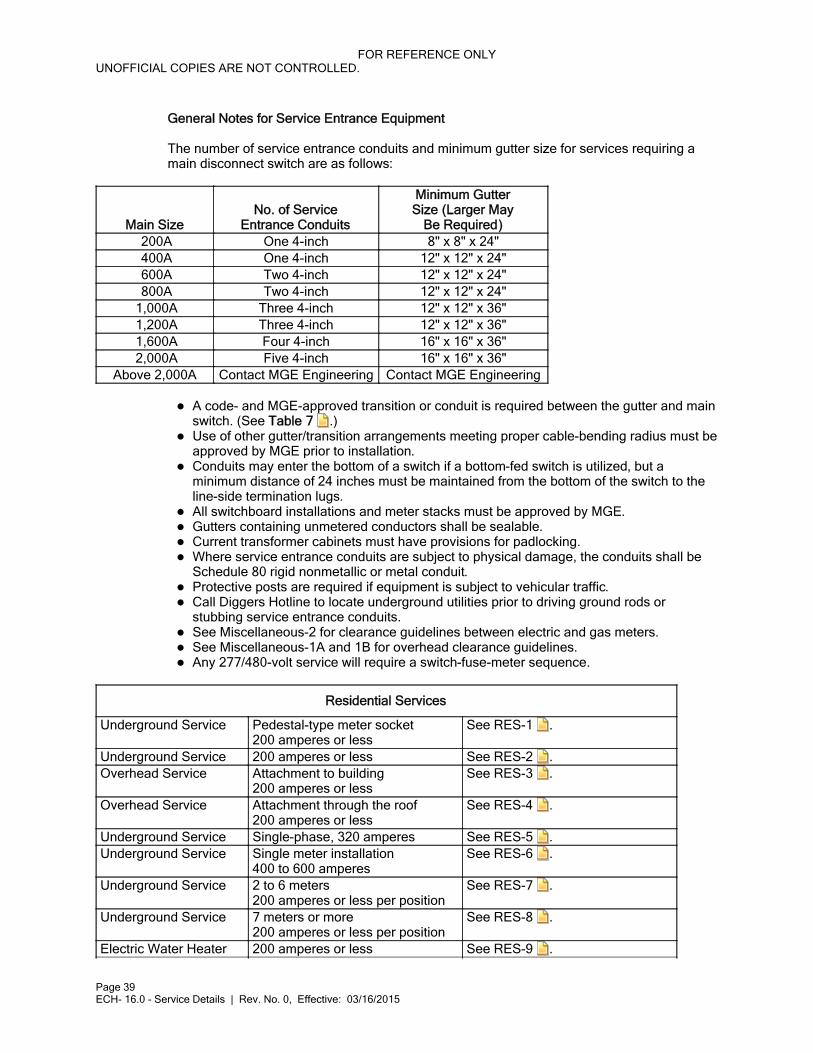
General Notes for Service Entrance Equipment
The number of service entrance conduits and minimum gutter size for services requiring a main disconnect switch are as follows:
Main SizeNo. of Service
Entrance Conduits
Minimum GutterSize (Larger May
Be Required) 200A One 4-inch 8" x 8" x 24" 400A One 4-inch 12" x 12" x 24" 600A Two 4-inch 12" x 12" x 24" 800A Two 4-inch 12" x 12" x 24"
1,000A Three 4-inch 12" x 12" x 36" 1,200A Three 4-inch 12" x 12" x 36" 1,600A Four 4-inch 16" x 16" x 36" 2,000A Five 4-inch 16" x 16" x 36"
Above 2,000A Contact MGE Engineering Contact MGE Engineering
A code- and MGE-approved transition or conduit is required between the gutter and main
switch. (See Table 7 .)Use of other gutter/transition arrangements meeting proper cable-bending radius must be
approved by MGE prior to installation.Conduits may enter the bottom of a switch if a bottom-fed switch is utilized, but a
minimum distance of 24 inches must be maintained from the bottom of the switch to the line-side termination lugs.All switchboard installations and meter stacks must be approved by MGE.
Gutters containing unmetered conductors shall be sealable.
Current transformer cabinets must have provisions for padlocking.
Where service entrance conduits are subject to physical damage, the conduits shall be
Schedule 80 rigid nonmetallic or metal conduit.Protective posts are required if equipment is subject to vehicular traffic.
Call Diggers Hotline to locate underground utilities prior to driving ground rods or
stubbing service entrance conduits.See Miscellaneous-2 for clearance guidelines between electric and gas meters.
See Miscellaneous-1A and 1B for overhead clearance guidelines.
Any 277/480-volt service will require a switch-fuse-meter sequence.
Residential Services
Underground Service Pedestal-type meter socket 200 amperes or less
See RES-1 .
Underground Service 200 amperes or less See RES-2 . Overhead Service Attachment to building
200 amperes or less See RES-3 .
Overhead Service Attachment through the roof 200 amperes or less
See RES-4 .
Underground Service Single-phase, 320 amperes See RES-5 . Underground Service Single meter installation
400 to 600 amperes See RES-6 .
Underground Service 2 to 6 meters 200 amperes or less per position
See RES-7 .
Underground Service 7 meters or more 200 amperes or less per position
See RES-8 .
Electric Water Heater 200 amperes or less See RES-9 .
FOR REFERENCE ONLYUNOFFICIAL COPIES ARE NOT CONTROLLED.
Page 40ECH- 16.0 - Service Details | Rev. No. 0, Effective: 03/16/2015
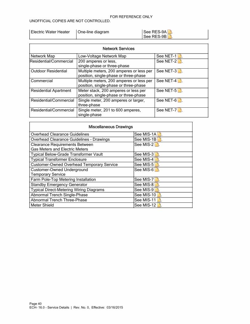
Electric Water Heater One-line diagram See RES-9A . See RES-9B .
Network Services
Network Map Low-Voltage Network Map See NET-1 .Residential/Commercial 200 amperes or less,
single-phase or three-phaseSee NET-2 .
Outdoor Residential Multiple meters, 200 amperes or less per position, single-phase or three-phase
See NET-3 .
Commercial Multiple meters, 200 amperes or less per position, single-phase or three-phase
See NET-4 .
Residential Apartment Meter stack, 200 amperes or less per position, single-phase or three-phase
See NET-5 .
Residential/Commercial Single meter, 200 amperes or larger, three-phase
See NET-6 .
Residential/Commercial Single meter, 201 to 600 amperes, single-phase
See NET-7 .
Miscellaneous Drawings
Overhead Clearance Guidelines See MIS-1A . Overhead Clearance Guidelines - Drawings See MIS-1B . Clearance Requirements Between Gas Meters and Electric Meters
See MIS-2 .
Typical Below-Grade Transformer Vault See MIS-3 . Typical Transformer Enclosure See MIS-4 . Customer-Owned Overhead Temporary Service See MIS-5 . Customer-Owned Underground Temporary Service
See MIS-6 .
Farm Pole-Top Metering Installation See MIS-7 . Standby Emergency Generator See MIS-8 . Typical Direct-Metering Wiring Diagrams See MIS-9 . Abnormal Trench Single-Phase See MIS-10 . Abnormal Trench Three-Phase See MIS-11 . Meter Shield See MIS-12 .

FOR REFERENCE ONLYUNOFFICIAL COPIES ARE NOT CONTROLLED.
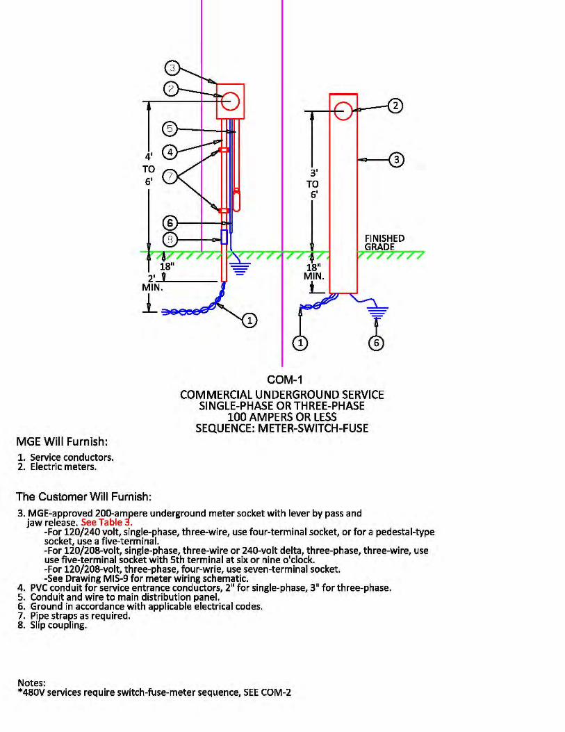
Page 41 16.0 - Service Details, Figure 16-1 - COM-1 | Rev. No. 0, Effective: 03/16/2015
Effective Date: 03/16/2015Revision No.: 016.0 - Service DetailsFigure 16-1 - COM-1
Double click on the icon and open the document.
COM-1.pdfCOM-1.pdf

FOR REFERENCE ONLYUNOFFICIAL COPIES ARE NOT CONTROLLED.
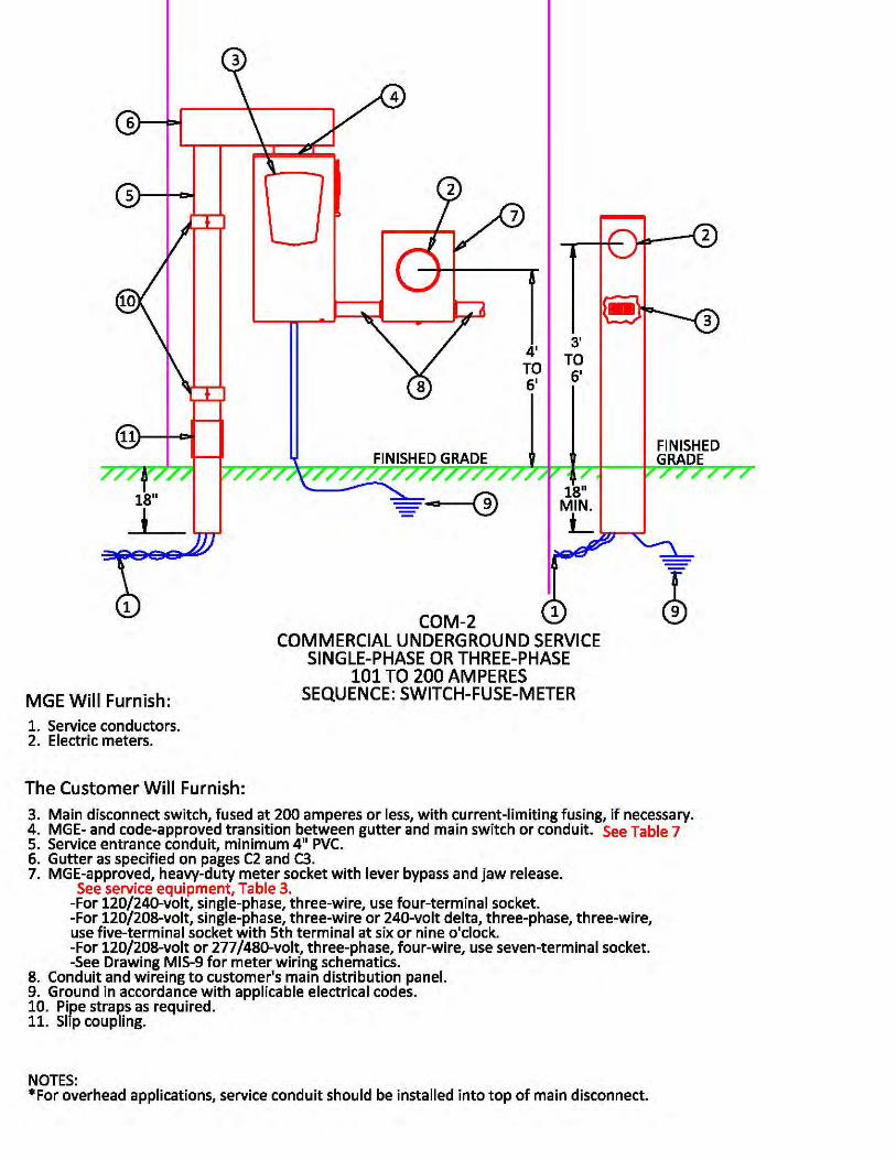
Page 42 16.0 - Service Details, Figure 16-2 - COM-2 | Rev. No. 0, Effective: 03/16/2015
Effective Date: 03/16/2015Revision No.: 016.0 - Service DetailsFigure 16-2 - COM-2
Double click on the icon and open the document.
COM-2.pdfCOM-2.pdf

FOR REFERENCE ONLYUNOFFICIAL COPIES ARE NOT CONTROLLED.
Page 43 16.0 - Service Details, Figure 16-3 - COM-3 | Rev. No. 0, Effective: 03/16/2015
Effective Date: 03/16/2015Revision No.: 016.0 - Service DetailsFigure 16-3 - COM-3
Double click on the icon and open the document.
COM-3.pdfCOM-3.pdf

FOR REFERENCE ONLYUNOFFICIAL COPIES ARE NOT CONTROLLED.
Page 44 16.0 - Service Details, Figure 16-4 - COM-4 | Rev. No. 0, Effective: 03/16/2015
Effective Date: 03/16/2015Revision No.: 016.0 - Service DetailsFigure 16-4 - COM-4
Double click on the icon and open the document.
COM-4.pdfCOM-4.pdf

FOR REFERENCE ONLYUNOFFICIAL COPIES ARE NOT CONTROLLED.
Page 45 16.0 - Service Details, Figure 16-5 - COM-5 | Rev. No. 0, Effective: 03/16/2015
Effective Date: 03/16/2015Revision No.: 016.0 - Service DetailsFigure 16-5 - COM-5
Double click on the icon and open the document.
COM-5.pdfCOM-5.pdf

FOR REFERENCE ONLYUNOFFICIAL COPIES ARE NOT CONTROLLED.
Page 46 16.0 - Service Details, Figure 16-6 - COM-6 | Rev. No. 0, Effective: 03/16/2015
Effective Date: 03/16/2015Revision No.: 016.0 - Service DetailsFigure 16-6 - COM-6
Double click on the icon and open the document.
COM-6.pdfCOM-6.pdf

FOR REFERENCE ONLYUNOFFICIAL COPIES ARE NOT CONTROLLED.
Page 47 16.0 - Service Details, Figure 16-7 - COM-7 | Rev. No. 0, Effective: 03/16/2015
Effective Date: 03/16/2015Revision No.: 016.0 - Service DetailsFigure 16-7 - COM-7
Double click on the icon and open the document.
COM-7.pdfCOM-7.pdf
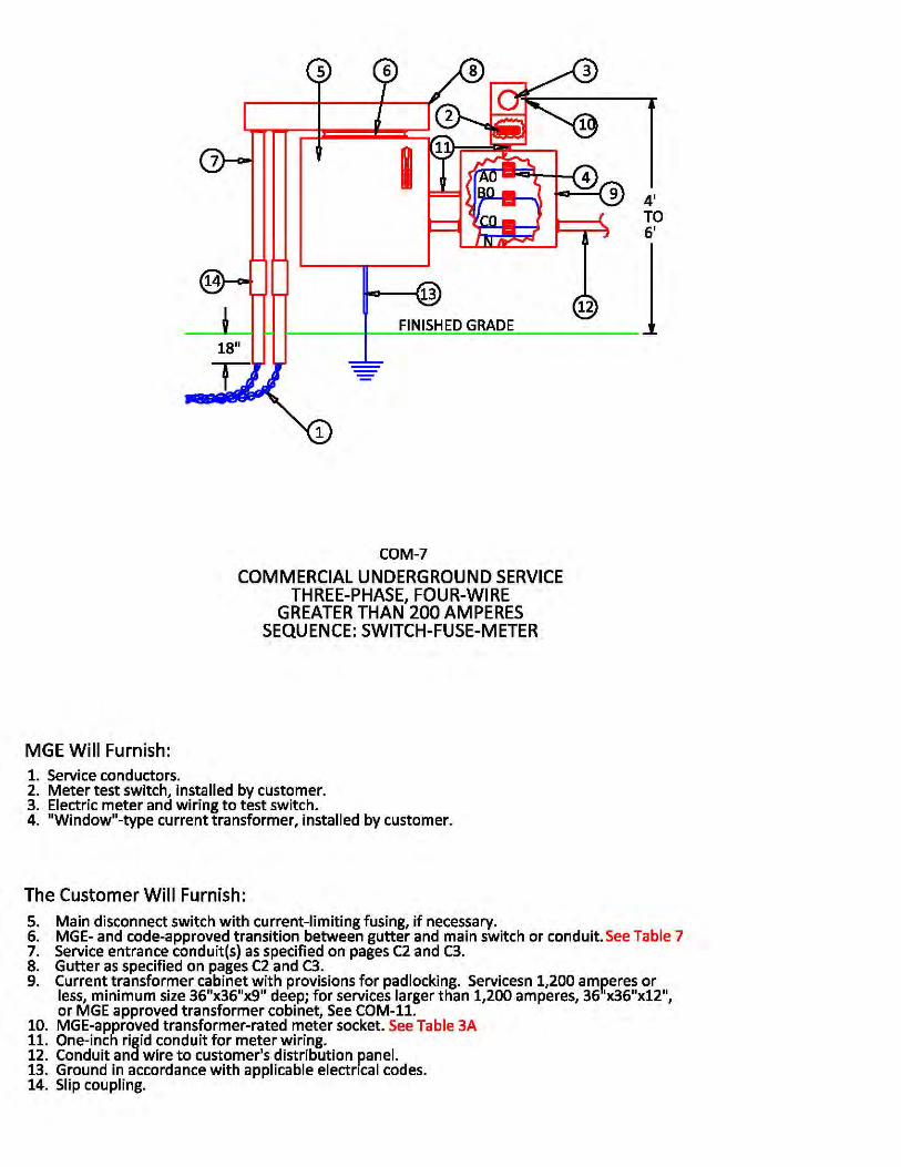

FOR REFERENCE ONLYUNOFFICIAL COPIES ARE NOT CONTROLLED.
Page 48 16.0 - Service Details, Figure 16-8 - COM-8 | Rev. No. 0, Effective: 03/16/2015
Effective Date: 03/16/2015Revision No.: 016.0 - Service DetailsFigure 16-8 - COM-8
Double click on the icon and open the document.
COM-8.pdfCOM-8.pdf
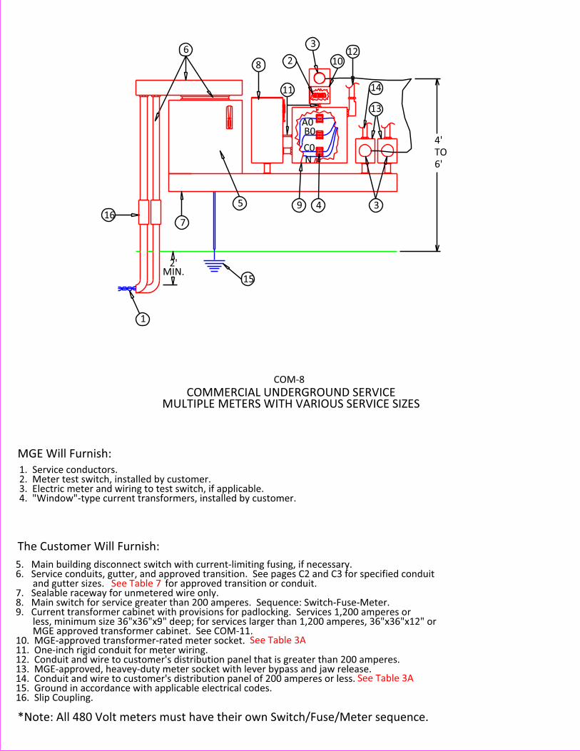

FOR REFERENCE ONLYUNOFFICIAL COPIES ARE NOT CONTROLLED.
Page 49 16.0 - Service Details, Figure 16-9 - COM-9 | Rev. No. 0, Effective: 03/16/2015
Effective Date: 03/16/2015Revision No.: 016.0 - Service DetailsFigure 16-9 - COM-9
Double click on the icon and open the document.
COM-9.pdfCOM-9.pdf
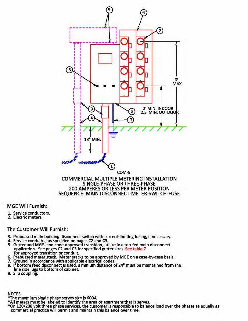

FOR REFERENCE ONLYUNOFFICIAL COPIES ARE NOT CONTROLLED.
Page 50 16.0 - Service Details, Figure 16-10 - COM-10 | Rev. No. 0, Effective: 03/16/2015
Effective Date: 03/16/2015Revision No.: 016.0 - Service DetailsFigure 16-10 - COM-10
Double click on the icon and open the document.
COM-10.pdfCOM-10.pdf
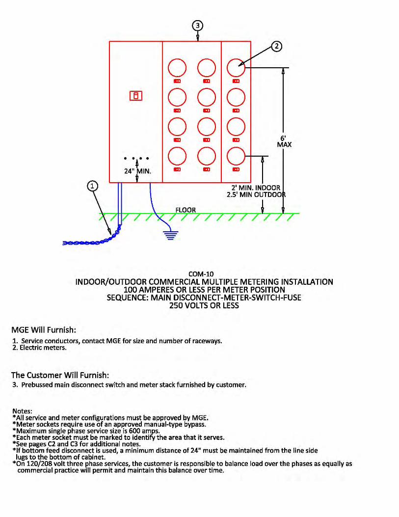

FOR REFERENCE ONLYUNOFFICIAL COPIES ARE NOT CONTROLLED.
Page 51 16.0 - Service Details, Figure 16-11 - COM-11 | Rev. No. 0, Effective: 03/16/2015
Effective Date: 03/16/2015Revision No.: 016.0 - Service DetailsFigure 16-11 - COM-11
Double click on the icon and open the document.
COM-11.pdfCOM-11.pdf
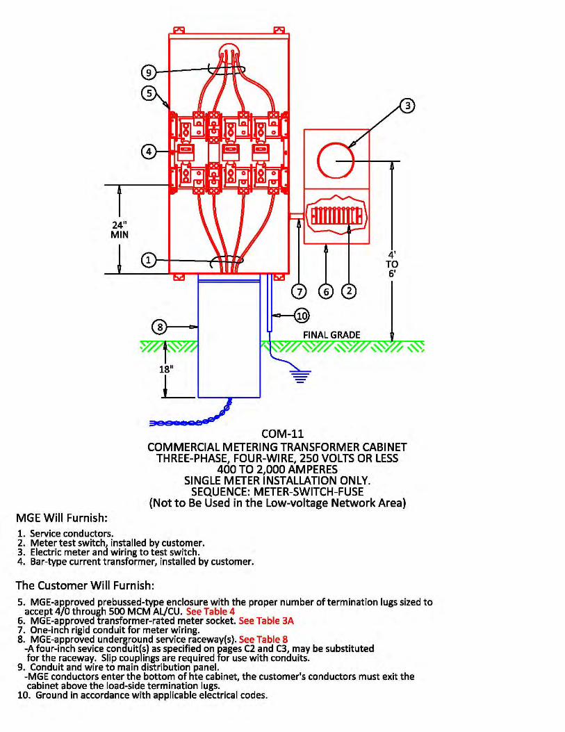

FOR REFERENCE ONLYUNOFFICIAL COPIES ARE NOT CONTROLLED.
Page 52 16.0 - Service Details, Figure 16-12 - COM-12 | Rev. No. 0, Effective: 03/16/2015
Effective Date: 03/16/2015Revision No.: 016.0 - Service DetailsFigure 16-12 - COM-12
Double click on the icon and open the document.
COM-12.pdfCOM-12.pdf
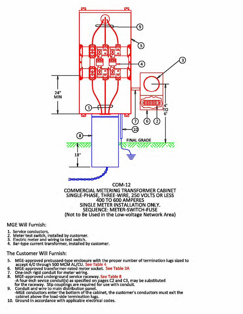

FOR REFERENCE ONLYUNOFFICIAL COPIES ARE NOT CONTROLLED.
Page 53 16.0 - Service Details, Figure 16-13 - COM-13 | Rev. No. 0, Effective: 03/16/2015
Effective Date: 03/16/2015Revision No.: 016.0 - Service DetailsFigure 16-13 - COM-13
Double click on the icon and open the document.
COM-13.pdfCOM-13.pdf
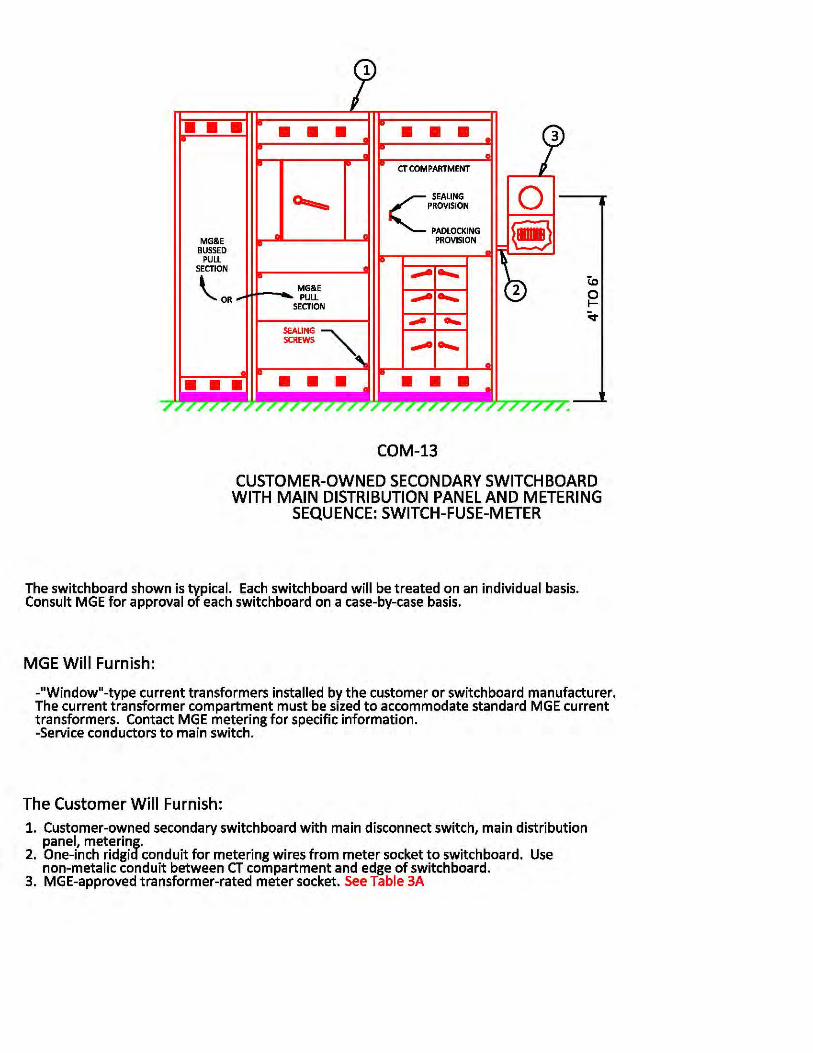
FOR REFERENCE ONLYUNOFFICIAL COPIES ARE NOT CONTROLLED.
Page 54 16.0 - Service Details, Figure 16-14 - COM-14 | Rev. No. 0, Effective: 03/16/2015
Effective Date: 03/16/2015Revision No.: 016.0 - Service DetailsFigure 16-14 - COM-14
Double click on the icon and open the document.
COM-14.pdfCOM-14.pdf
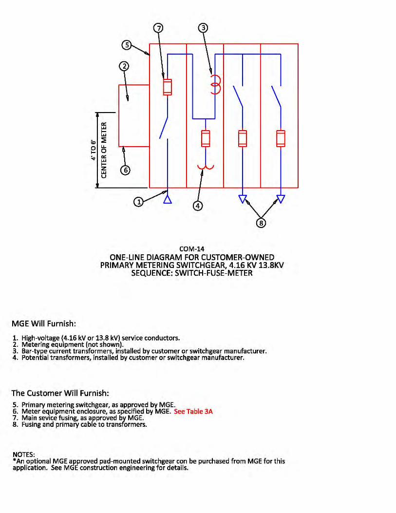

FOR REFERENCE ONLYUNOFFICIAL COPIES ARE NOT CONTROLLED.
Page 55 16.0 - Service Details, Figure 16-15 - RES-1 | Rev. No. 0, Effective: 03/16/2015
Effective Date: 03/16/2015Revision No.: 016.0 - Service DetailsFigure 16-15 - RES-1
Double click on the icon and open the document.
RES-1.pdfRES-1.pdf
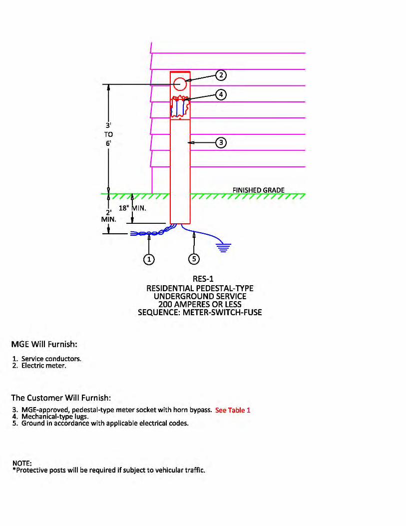

FOR REFERENCE ONLYUNOFFICIAL COPIES ARE NOT CONTROLLED.
Page 56 16.0 - Service Details, Figure 16-16 - RES-2 | Rev. No. 0, Effective: 03/16/2015
Effective Date: 03/16/2015Revision No.: 016.0 - Service DetailsFigure 16-16 - RES-2
Double click on the icon and open the document.
RES-2.pdfRES-2.pdf
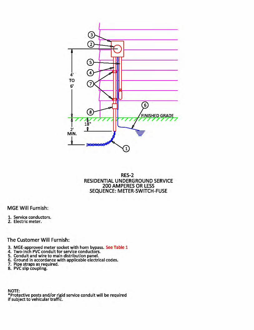

FOR REFERENCE ONLYUNOFFICIAL COPIES ARE NOT CONTROLLED.
Page 57 16.0 - Service Details, Figure 16-17 - RES-3 | Rev. No. 0, Effective: 03/16/2015
Effective Date: 03/16/2015Revision No.: 016.0 - Service DetailsFigure 16-17 - RES-3
Double click on the icon and open the document.
RES-3.pdfRES-3.pdf
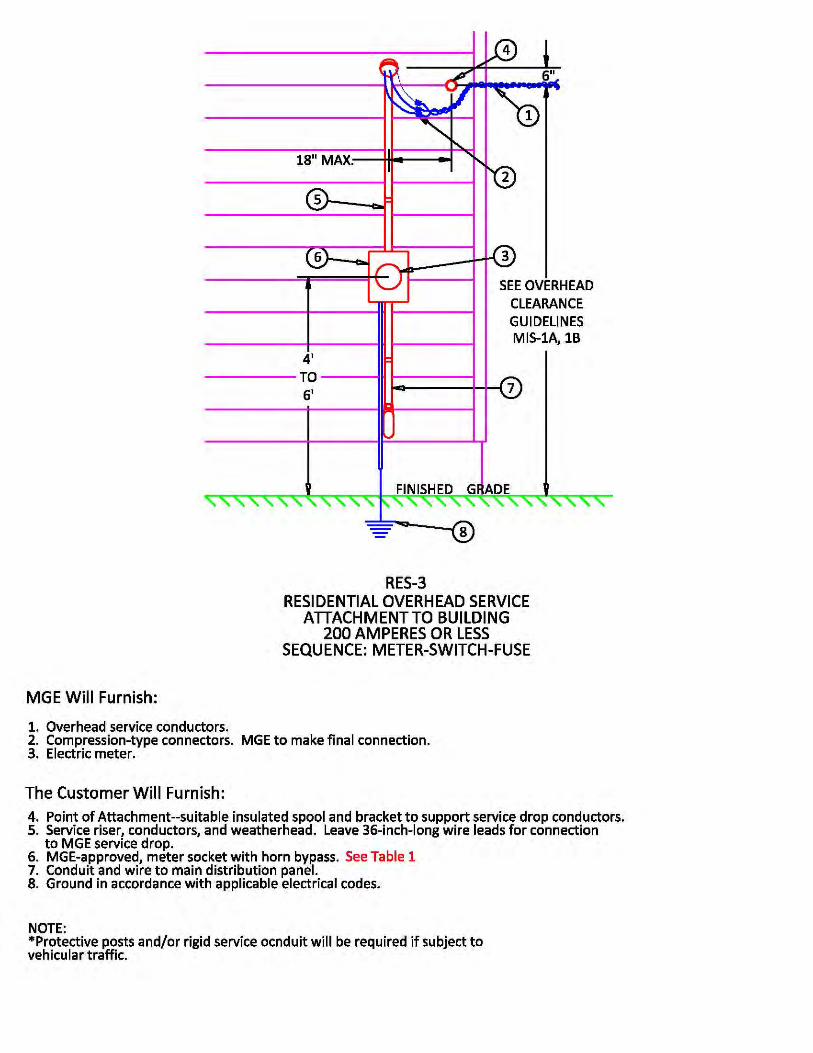
FOR REFERENCE ONLYUNOFFICIAL COPIES ARE NOT CONTROLLED.
Page 58 16.0 - Service Details, Figure 16-18 - RES-4 | Rev. No. 0, Effective: 03/16/2015
Effective Date: 03/16/2015Revision No.: 016.0 - Service DetailsFigure 16-18 - RES-4
Double click on the icon and open the document.
RES-4.pdfRES-4.pdf
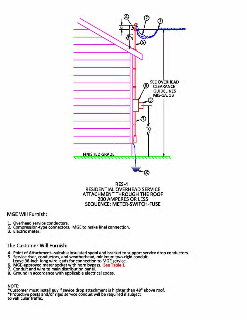

FOR REFERENCE ONLYUNOFFICIAL COPIES ARE NOT CONTROLLED.
Page 59 16.0 - Service Details, Figure 16-19 - RES-5 | Rev. No. 0, Effective: 03/16/2015
Effective Date: 03/16/2015Revision No.: 016.0 - Service DetailsFigure 16-19 - RES-5
Double click on the icon and open the document.
RES-5.pdfRES-5.pdf
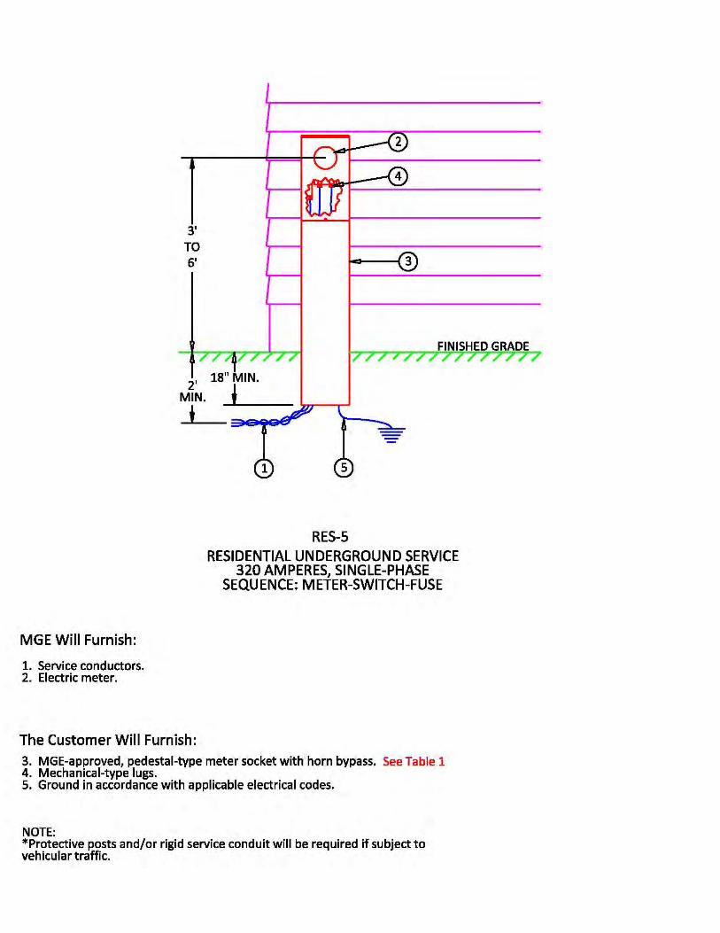

FOR REFERENCE ONLYUNOFFICIAL COPIES ARE NOT CONTROLLED.
Page 60 16.0 - Service Details, Figure 16-20 - RES-6 | Rev. No. 0, Effective: 03/16/2015
Effective Date: 03/16/2015Revision No.: 016.0 - Service DetailsFigure 16-20 - RES-6
Double click on the icon and open the document.
RES-6.pdfRES-6.pdf
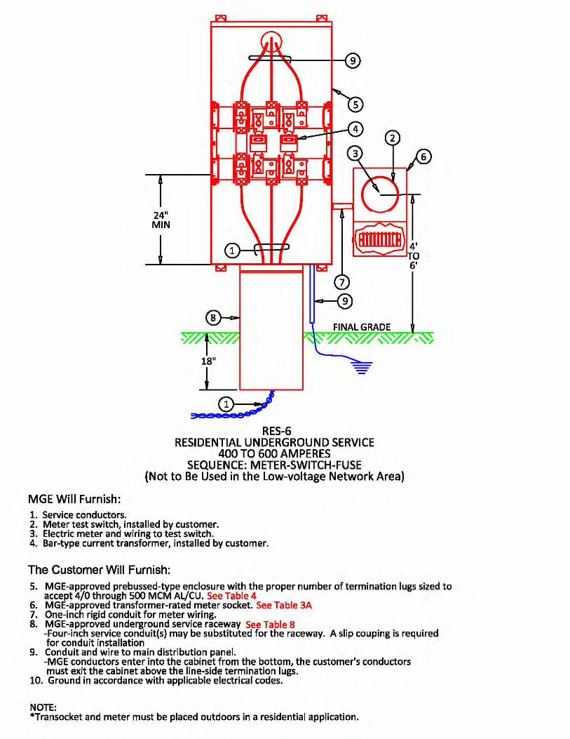

FOR REFERENCE ONLYUNOFFICIAL COPIES ARE NOT CONTROLLED.
Page 61 16.0 - Service Details, Figure 16-21 - RES-7 | Rev. No. 0, Effective: 03/16/2015
Effective Date: 03/16/2015Revision No.: 016.0 - Service DetailsFigure 16-21 - RES-7
Double click on the icon and open the document.
RES-7.pdfRES-7.pdf
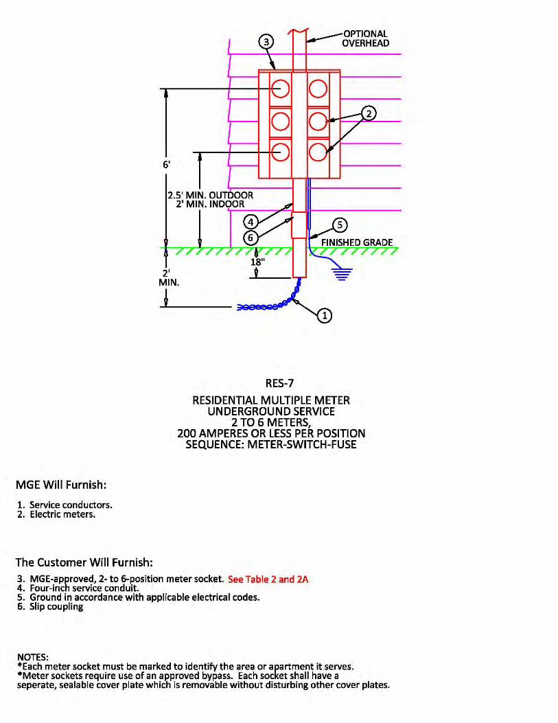
FOR REFERENCE ONLYUNOFFICIAL COPIES ARE NOT CONTROLLED.
Page 62 16.0 - Service Details, Figure 16-22 - RES-8 | Rev. No. 0, Effective: 03/16/2015
Effective Date: 03/16/2015Revision No.: 016.0 - Service DetailsFigure 16-22 - RES-8
Double click on the icon and open the document.
RES-8.pdfRES-8.pdf
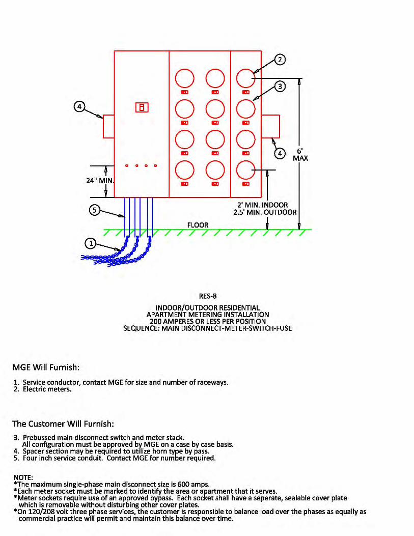

FOR REFERENCE ONLYUNOFFICIAL COPIES ARE NOT CONTROLLED.
Page 63 16.0 - Service Details, Figure 16-23 - RES-9 | Rev. No. 0, Effective: 03/16/2015
Effective Date: 03/16/2015Revision No.: 016.0 - Service DetailsFigure 16-23 - RES-9
Double click on the icon and open the document.
RES-9.pdfRES-9.pdf
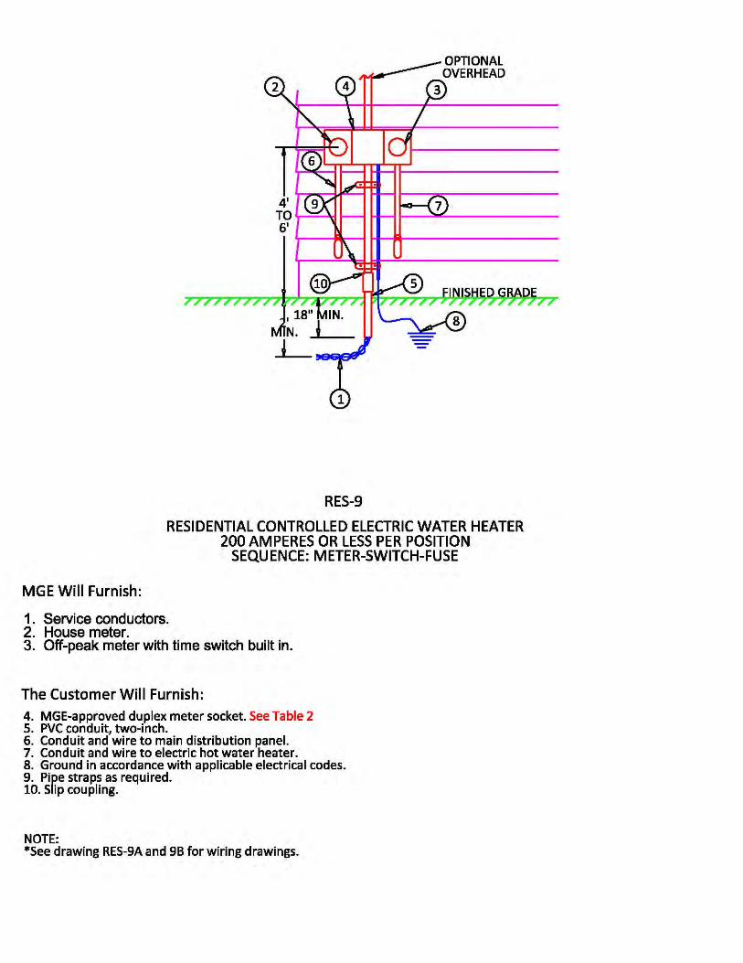

FOR REFERENCE ONLYUNOFFICIAL COPIES ARE NOT CONTROLLED.
Page 64 16.0 - Service Details, Figure 16-24 - RES-9A | Rev. No. 0, Effective: 03/16/2015
Effective Date: 03/16/2015Revision No.: 016.0 - Service DetailsFigure 16-24 - RES-9A
Double click on the icon and open the document.
RES-9A.pdfRES-9A.pdf
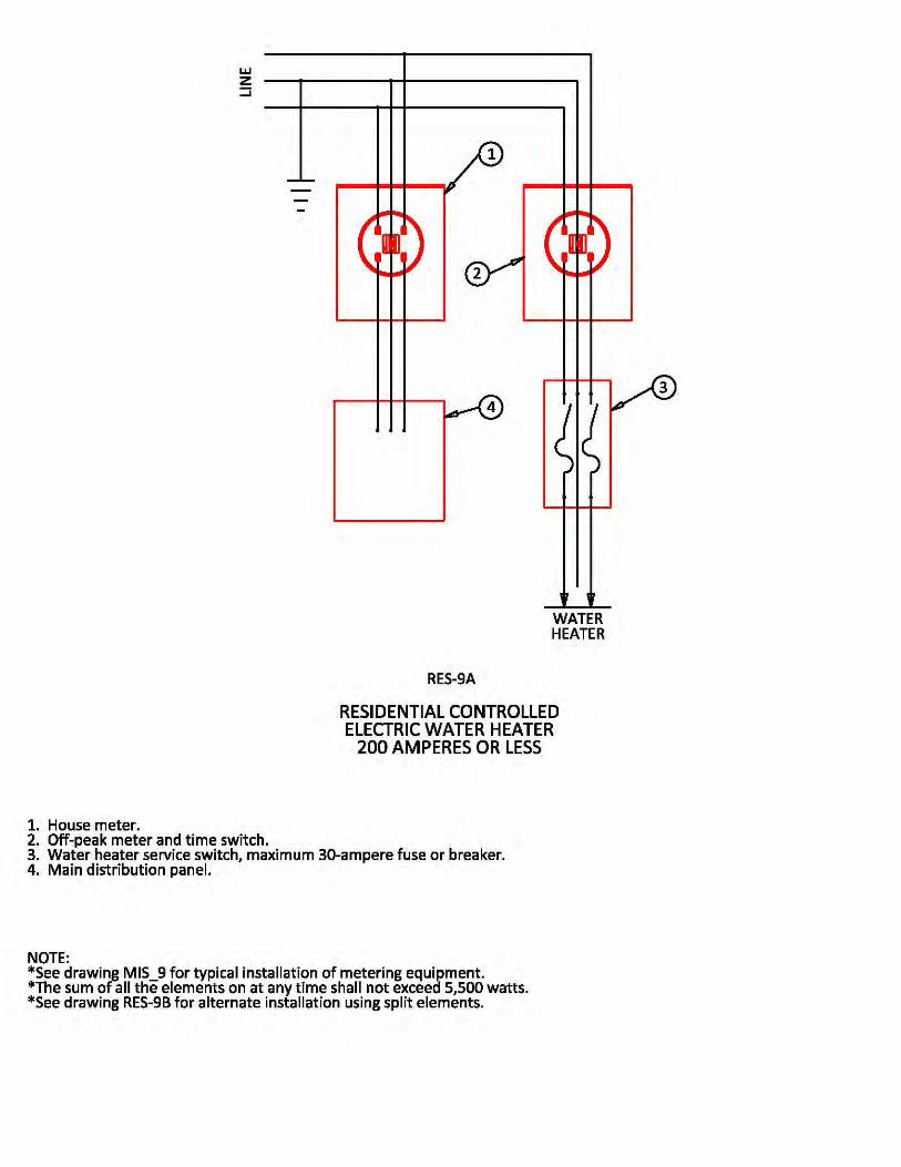

FOR REFERENCE ONLYUNOFFICIAL COPIES ARE NOT CONTROLLED.
Page 65 16.0 - Service Details, Figure 16-25 - RES-9B | Rev. No. 0, Effective: 03/16/2015
Effective Date: 03/16/2015Revision No.: 016.0 - Service DetailsFigure 16-25 - RES-9B
Double click on the icon and open the document.
RES-9B.pdfRES-9B.pdf
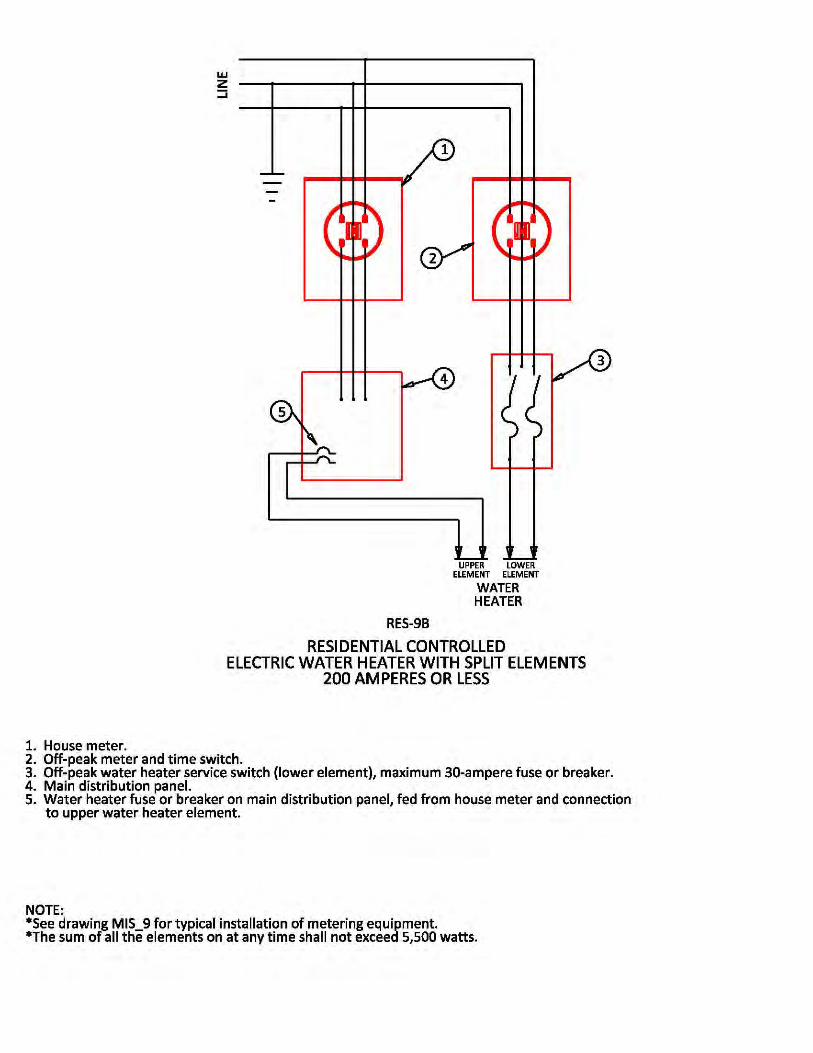

FOR REFERENCE ONLYUNOFFICIAL COPIES ARE NOT CONTROLLED.
Page 66 16.0 - Service Details, Figure 16-26 - NET-1 | Rev. No. 0, Effective: 03/16/2015
Effective Date: 03/16/2015Revision No.: 016.0 - Service DetailsFigure 16-26 - NET-1
Double click on the icon and open the document.
NET-1.pdfNET-1.pdf
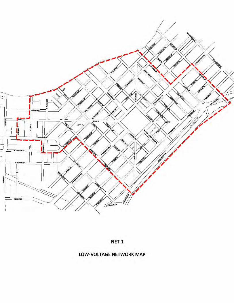

FOR REFERENCE ONLYUNOFFICIAL COPIES ARE NOT CONTROLLED.
Page 67 16.0 - Service Details, Figure 16-27 - NET-2 | Rev. No. 0, Effective: 03/16/2015
Effective Date: 03/16/2015Revision No.: 016.0 - Service DetailsFigure 16-27 - NET-2
Double click on the icon and open the document.
NET-2.pdfNET-2.pdf
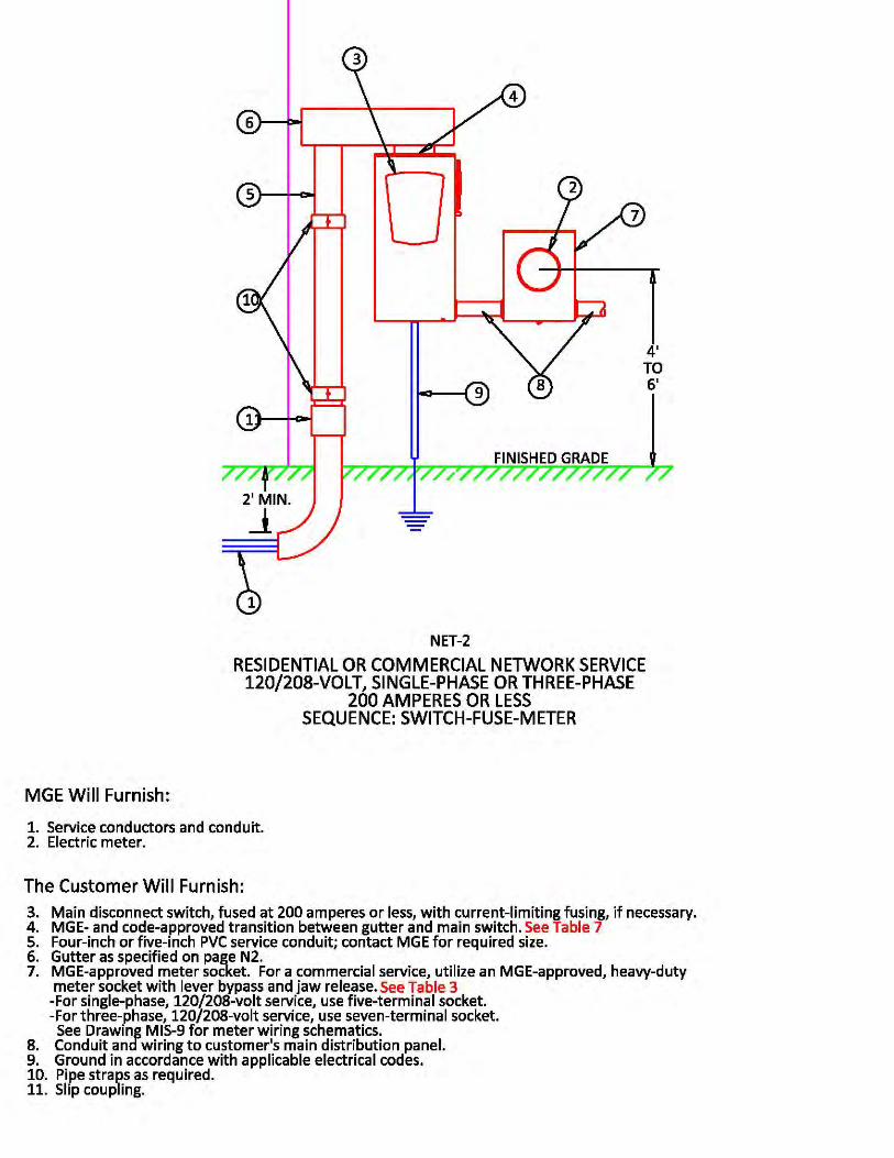

FOR REFERENCE ONLYUNOFFICIAL COPIES ARE NOT CONTROLLED.
Page 68 16.0 - Service Details, Figure 16-28 - NET-3 | Rev. No. 0, Effective: 03/16/2015
Effective Date: 03/16/2015Revision No.: 016.0 - Service DetailsFigure 16-28 - NET-3
Double click on the icon and open the document.
NET-3.pdfNET-3.pdf
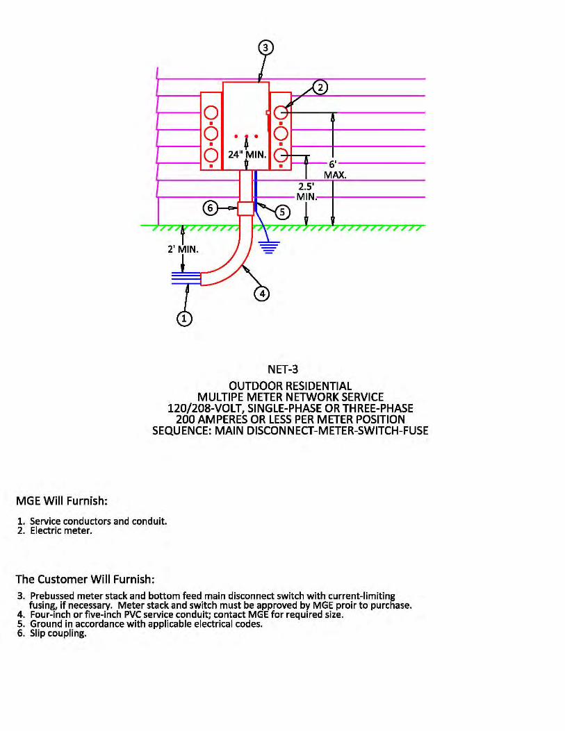

FOR REFERENCE ONLYUNOFFICIAL COPIES ARE NOT CONTROLLED.
Page 69 16.0 - Service Details, Figure 16-29 - NET-4 | Rev. No. 0, Effective: 03/16/2015
Effective Date: 03/16/2015Revision No.: 016.0 - Service DetailsFigure 16-29 - NET-4
Double click on the icon and open the document.
NET-4.pdfNET-4.pdf
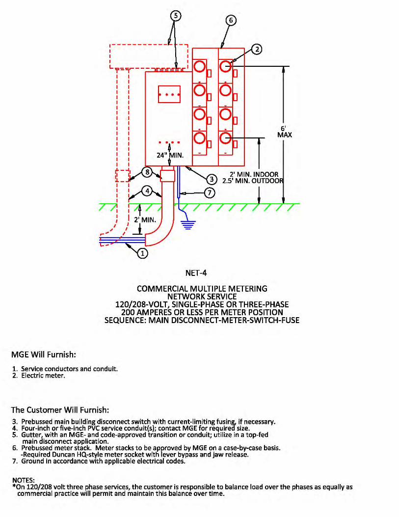

FOR REFERENCE ONLYUNOFFICIAL COPIES ARE NOT CONTROLLED.
Page 70 16.0 - Service Details, Figure 16-30 - NET-5 | Rev. No. 0, Effective: 03/16/2015
Effective Date: 03/16/2015Revision No.: 016.0 - Service DetailsFigure 16-30 - NET-5
Double click on the icon and open the document.
NET-5.pdfNET-5.pdf
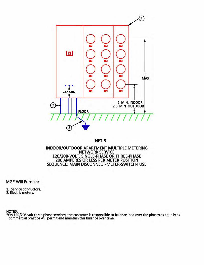

FOR REFERENCE ONLYUNOFFICIAL COPIES ARE NOT CONTROLLED.
Page 71 16.0 - Service Details, Figure 16-31 - NET-6 | Rev. No. 0, Effective: 03/16/2015
Effective Date: 03/16/2015Revision No.: 016.0 - Service DetailsFigure 16-31 - NET-6
Double click on the icon and open the document.
NET-6.pdfNET-6.pdf
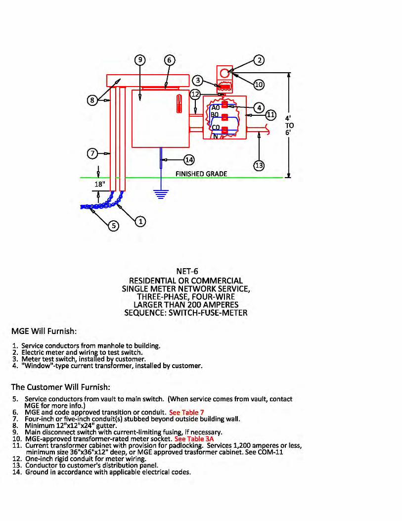

FOR REFERENCE ONLYUNOFFICIAL COPIES ARE NOT CONTROLLED.
Page 72 16.0 - Service Details, Figure 16-32 - NET-7 | Rev. No. 0, Effective: 03/16/2015
Effective Date: 03/16/2015Revision No.: 016.0 - Service DetailsFigure 16-32 - NET-7
Double click on the icon and open the document.
NET-7.pdfNET-7.pdf
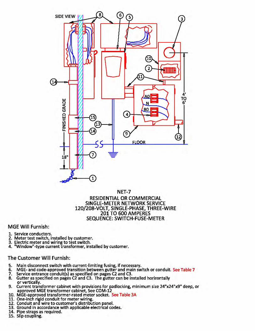

FOR REFERENCE ONLYUNOFFICIAL COPIES ARE NOT CONTROLLED.
Page 73 16.0 - Service Details, Figure 16-33 - MIS-1A | Rev. No. 0, Effective: 03/16/2015
Effective Date: 03/16/2015Revision No.: 016.0 - Service DetailsFigure 16-33 - MIS-1A
Double click on the icon and open the document.
MIS-1A.pdfMIS-1A.pdf
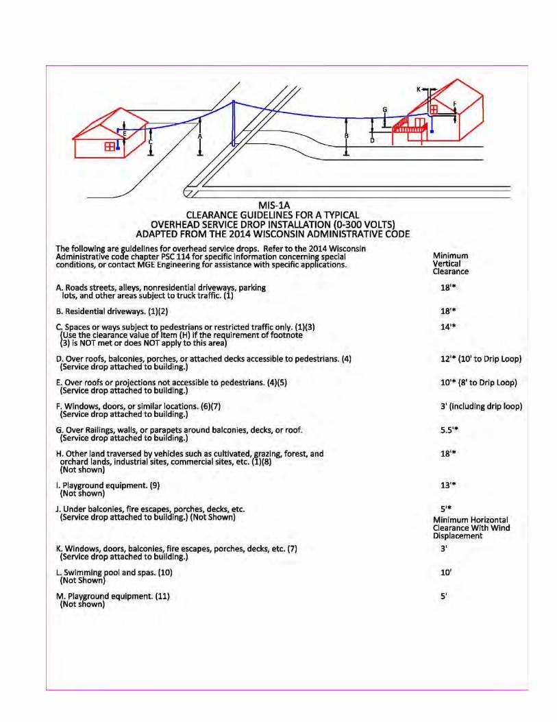


FOR REFERENCE ONLYUNOFFICIAL COPIES ARE NOT CONTROLLED.
Page 74 16.0 - Service Details, Figure 16-34 - MIS-1B | Rev. No. 0, Effective: 03/16/2015
Effective Date: 03/16/2015Revision No.: 016.0 - Service DetailsFigure 16-34 - MIS-1B
Double click on the icon and open the document.
MIS-1B.pdfMIS-1B.pdf
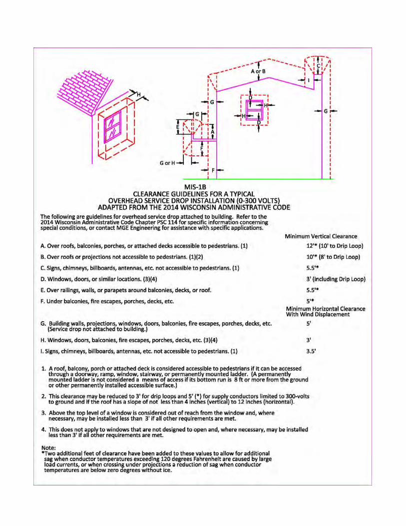

FOR REFERENCE ONLYUNOFFICIAL COPIES ARE NOT CONTROLLED.
Page 75 16.0 - Service Details, Figure 16-35 - MIS-2 | Rev. No. 0, Effective: 03/16/2015
Effective Date: 03/16/2015Revision No.: 016.0 - Service DetailsFigure 16-35 - MIS-2
Double click on the icon and open the document.
MIS-2.pdfMIS-2.pdf
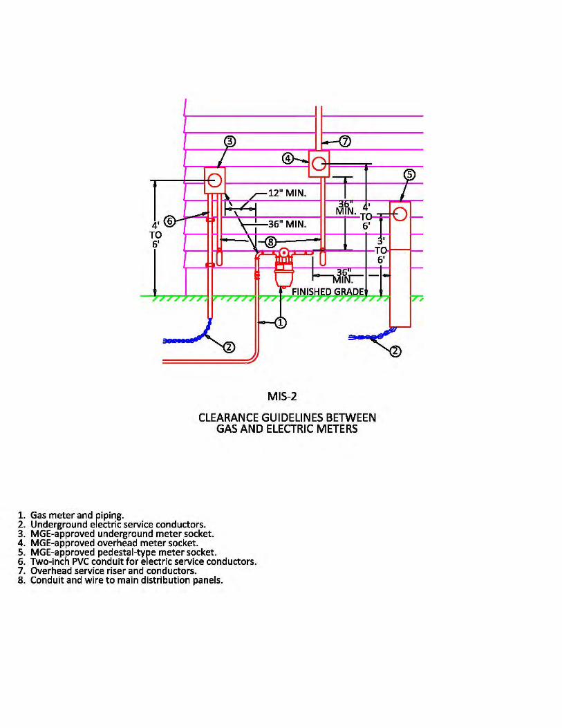

FOR REFERENCE ONLYUNOFFICIAL COPIES ARE NOT CONTROLLED.
Page 76 16.0 - Service Details, Figure 16-36 - MIS-3 | Rev. No. 0, Effective: 03/16/2015
Effective Date: 03/16/2015Revision No.: 016.0 - Service DetailsFigure 16-36 - MIS-3
Double click on the icon and open the document.
MIS-3.pdfMIS-3.pdf
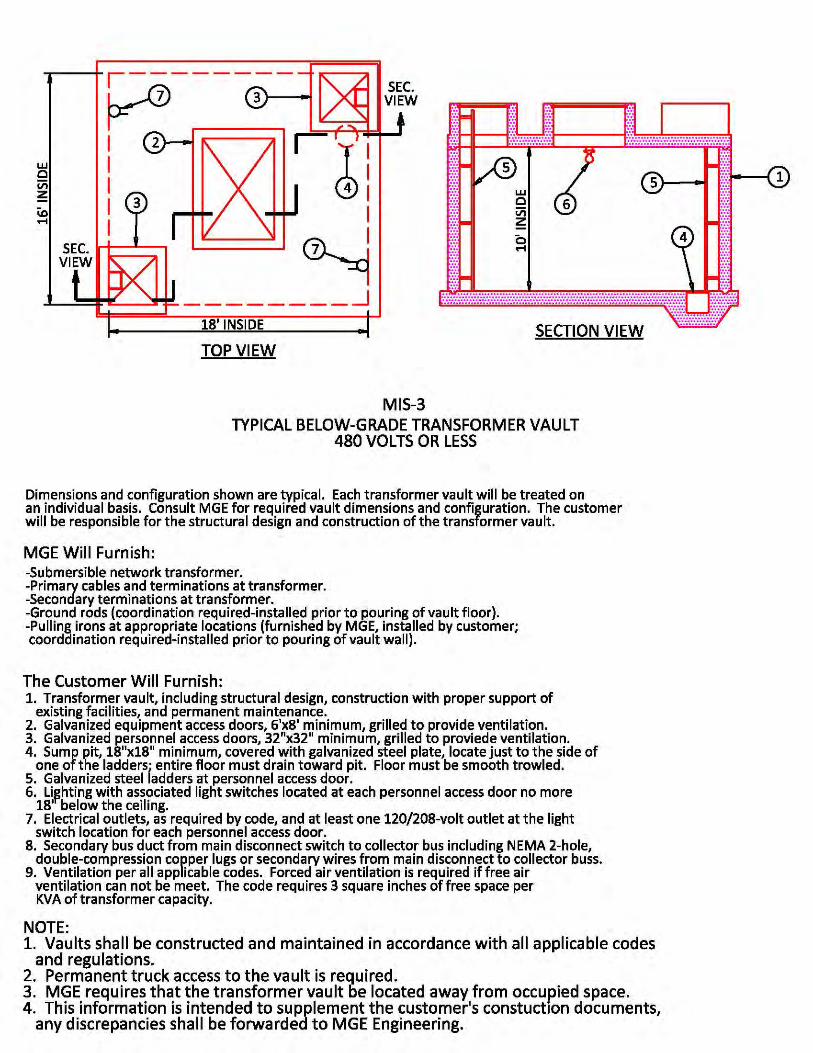
FOR REFERENCE ONLYUNOFFICIAL COPIES ARE NOT CONTROLLED.
Page 77 16.0 - Service Details, Figure 16-37 - MIS-4 | Rev. No. 0, Effective: 03/16/2015
Effective Date: 03/16/2015Revision No.: 016.0 - Service DetailsFigure 16-37 - MIS-4
Double click on the icon and open the document.
MIS-4.pdfMIS-4.pdf
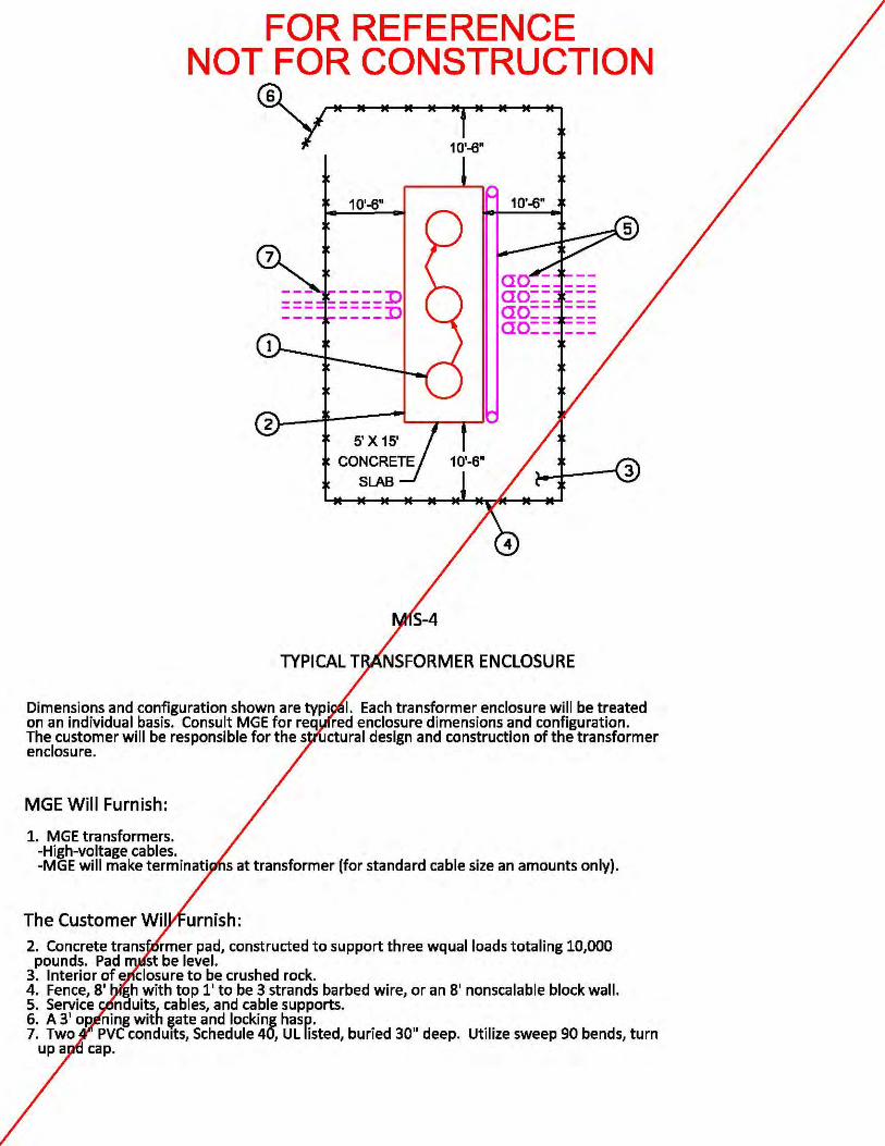

FOR REFERENCE ONLYUNOFFICIAL COPIES ARE NOT CONTROLLED.
Page 78 16.0 - Service Details, Figure 16-38 - MIS-5 | Rev. No. 0, Effective: 03/16/2015
Effective Date: 03/16/2015Revision No.: 016.0 - Service DetailsFigure 16-38 - MIS-5
Double click on the icon and open the document.
MIS-5.pdfMIS-5.pdf
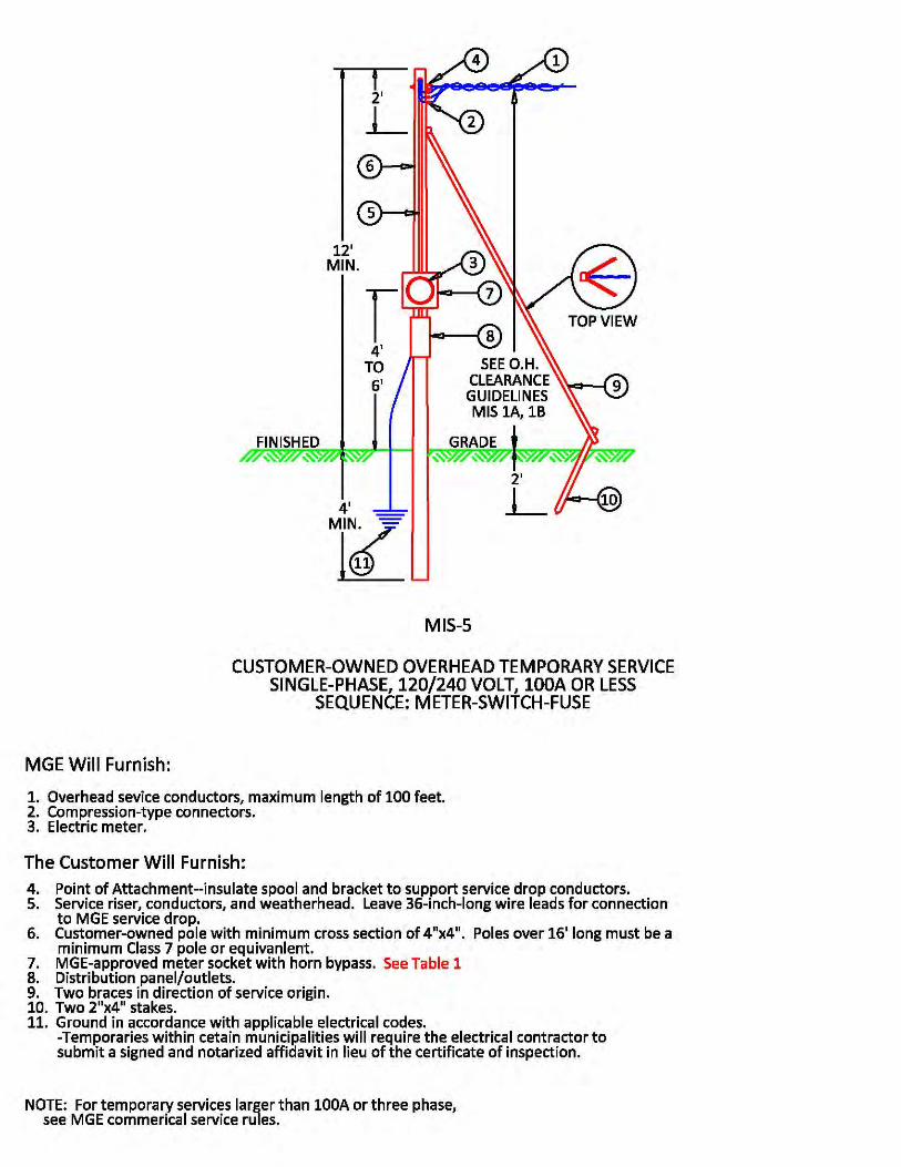

FOR REFERENCE ONLYUNOFFICIAL COPIES ARE NOT CONTROLLED.
Page 79 16.0 - Service Details, Figure 16-39 - MIS-6 | Rev. No. 0, Effective: 03/16/2015
Effective Date: 03/16/2015Revision No.: 016.0 - Service DetailsFigure 16-39 - MIS-6
Double click on the icon and open the document.
MIS-6.pdfMIS-6.pdf
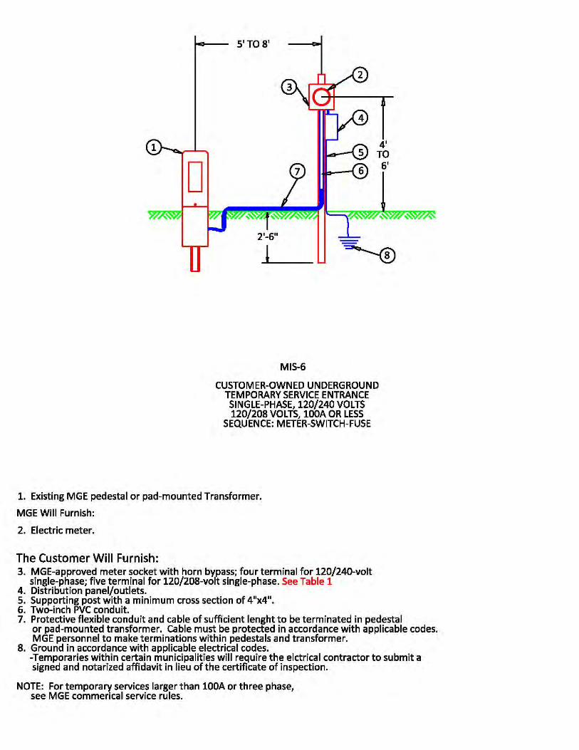

FOR REFERENCE ONLYUNOFFICIAL COPIES ARE NOT CONTROLLED.
Page 80 16.0 - Service Details, Figure 16-40 - MIS-7 | Rev. No. 0, Effective: 03/16/2015
Effective Date: 03/16/2015Revision No.: 016.0 - Service DetailsFigure 16-40 - MIS-7
Double click on the icon and open the document.
MIS-7.pdfMIS-7.pdf
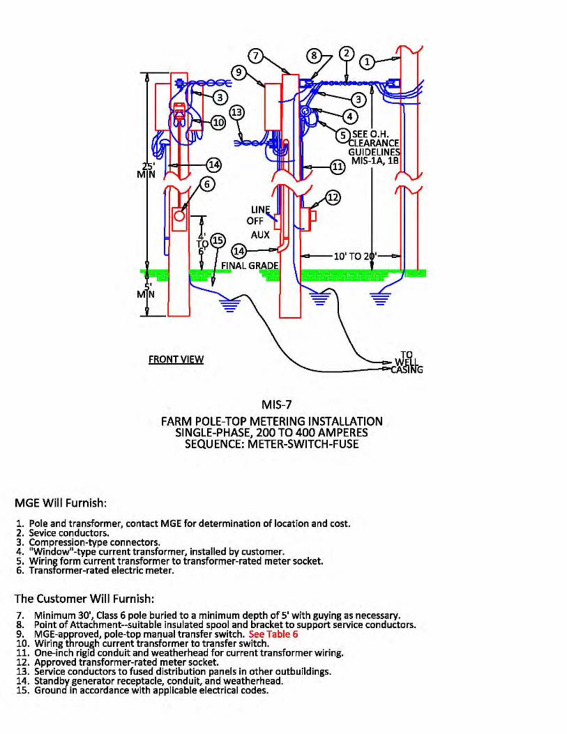
FOR REFERENCE ONLYUNOFFICIAL COPIES ARE NOT CONTROLLED.
Page 81 16.0 - Service Details, Figure 16-41 - MIS-8 | Rev. No. 0, Effective: 03/16/2015
Effective Date: 03/16/2015Revision No.: 016.0 - Service DetailsFigure 16-41 - MIS-8
Double click on the icon and open the document.
MIS-8.pdfMIS-8.pdf
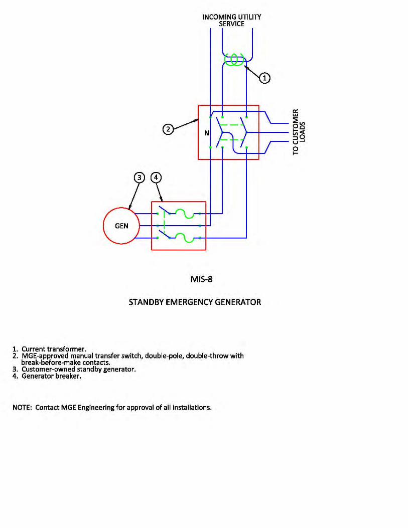

FOR REFERENCE ONLYUNOFFICIAL COPIES ARE NOT CONTROLLED.
Page 82 16.0 - Service Details, Figure 16-42 - MIS-9 | Rev. No. 0, Effective: 03/16/2015
Effective Date: 03/16/2015Revision No.: 016.0 - Service DetailsFigure 16-42 - MIS-9
Double click on the icon and open the document.
MIS-9.pdfMIS-9.pdf
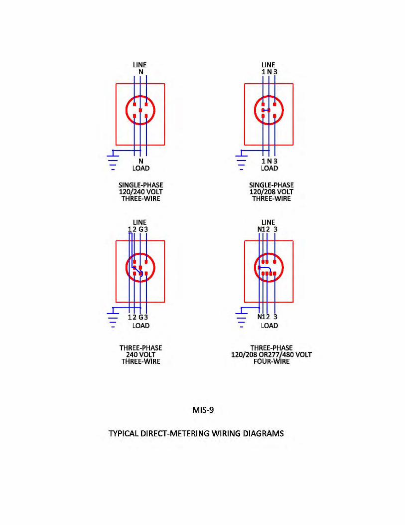

FOR REFERENCE ONLYUNOFFICIAL COPIES ARE NOT CONTROLLED.
Page 83 16.0 - Service Details, Figure 16-43 - MIS-10 | Rev. No. 0, Effective: 03/16/2015
Effective Date: 03/16/2015Revision No.: 016.0 - Service DetailsFigure 16-43 - MIS-10
Double click on the icon and open the document.
MIS-10.pdfMIS-10.pdf
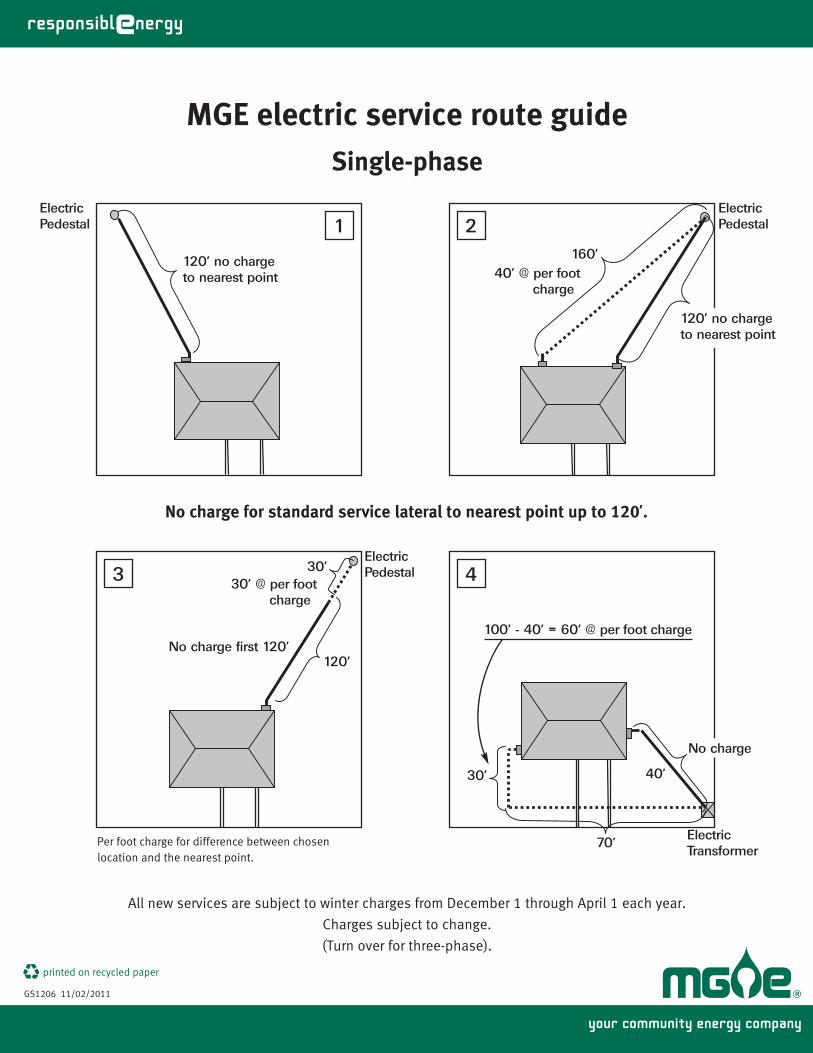
your community energy company
printed on recycled paper
MGE electric service route guideSingle-phase
GS1206 11/02/2011
All new services are subject to winter charges from December 1 through April 1 each year.
Charges subject to change.
(Turn over for three-phase).
No charge for standard service lateral to nearest point up to 120’.
120’ no chargeto nearest point
ElectricPedestal
ElectricPedestal
160’40’ @ per foot charge
120’ no chargeto nearest point
ElectricPedestal
ElectricTransformer
120’
30’30’ @ per foot charge
70’
30’
100’ - 40’ = 60’ @ per foot charge
No charge
No charge first 120’
40’
Per foot charge for difference between chosenlocation and the nearest point.
21
3 4

FOR REFERENCE ONLYUNOFFICIAL COPIES ARE NOT CONTROLLED.
Page 84 16.0 - Service Details, Figure 16-44 - MIS-11 | Rev. No. 0, Effective: 03/16/2015
Effective Date: 03/16/2015Revision No.: 016.0 - Service DetailsFigure 16-44 - MIS-11
Double click on the icon and open the document.
MIS-11.pdfMIS-11.pdf
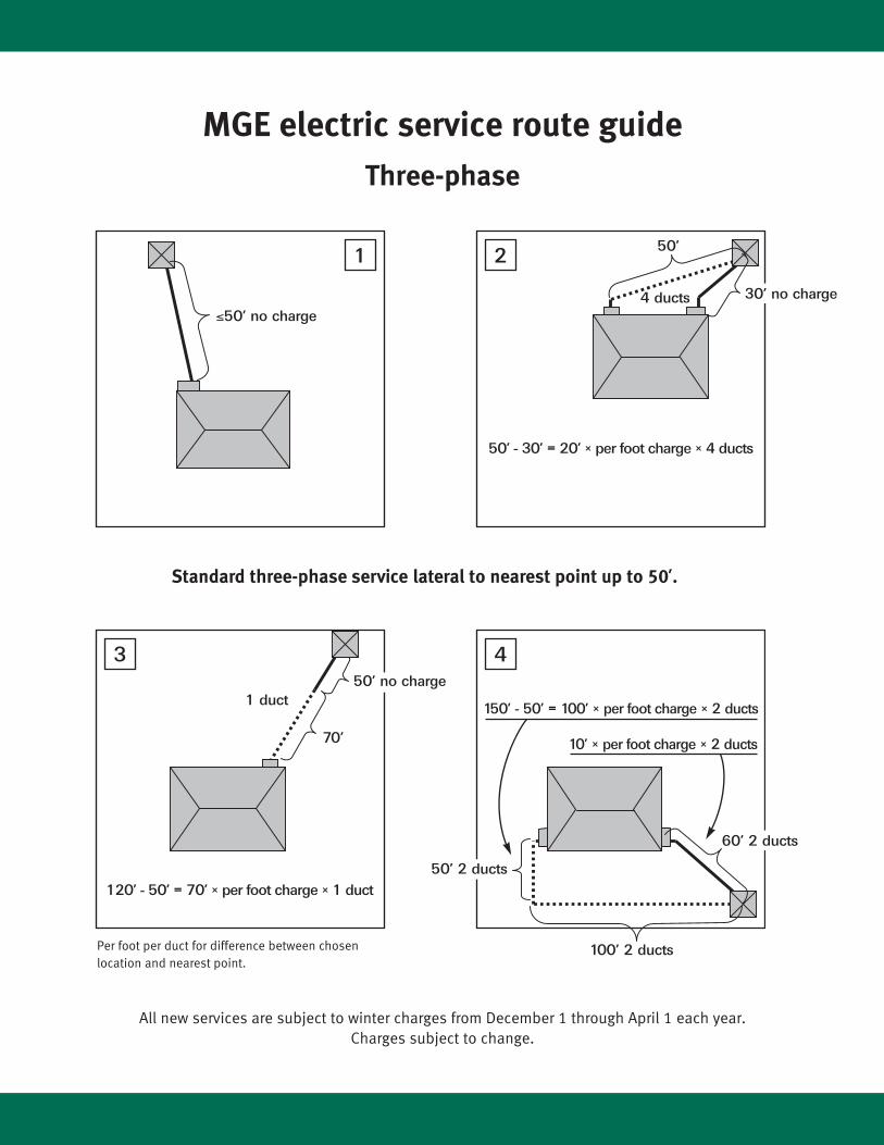
MGE electric service route guideThree-phase
All new services are subject to winter charges from December 1 through April 1 each year.Charges subject to change.
Standard three-phase service lateral to nearest point up to 50’.
4 ducts
50’ - 30’ = 20’ × per foot charge × 4 ducts
50’
≤50’ no charge
30’ no charge
120’ - 50’ = 70’ × per foot charge × 1 duct
150’ - 50’ = 100’ × per foot charge × 2 ducts
50’ no charge
70’
1 duct
100’ 2 ducts
50’ 2 ducts
60’ 2 ducts
10’ × per foot charge × 2 ducts
Per foot per duct for difference between chosenlocation and nearest point.
1 2
3 4

FOR REFERENCE ONLYUNOFFICIAL COPIES ARE NOT CONTROLLED.
Page 85 16.0 - Service Details, Figure 16-45 - MIS-12 | Rev. No. 0, Effective: 03/16/2015
Effective Date: 03/16/2015Revision No.: 016.0 - Service DetailsFigure 16-45 - MIS-12
Double click on the icon and open the document.
MIS-12.pdfMIS-12.pdf
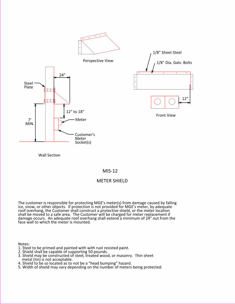
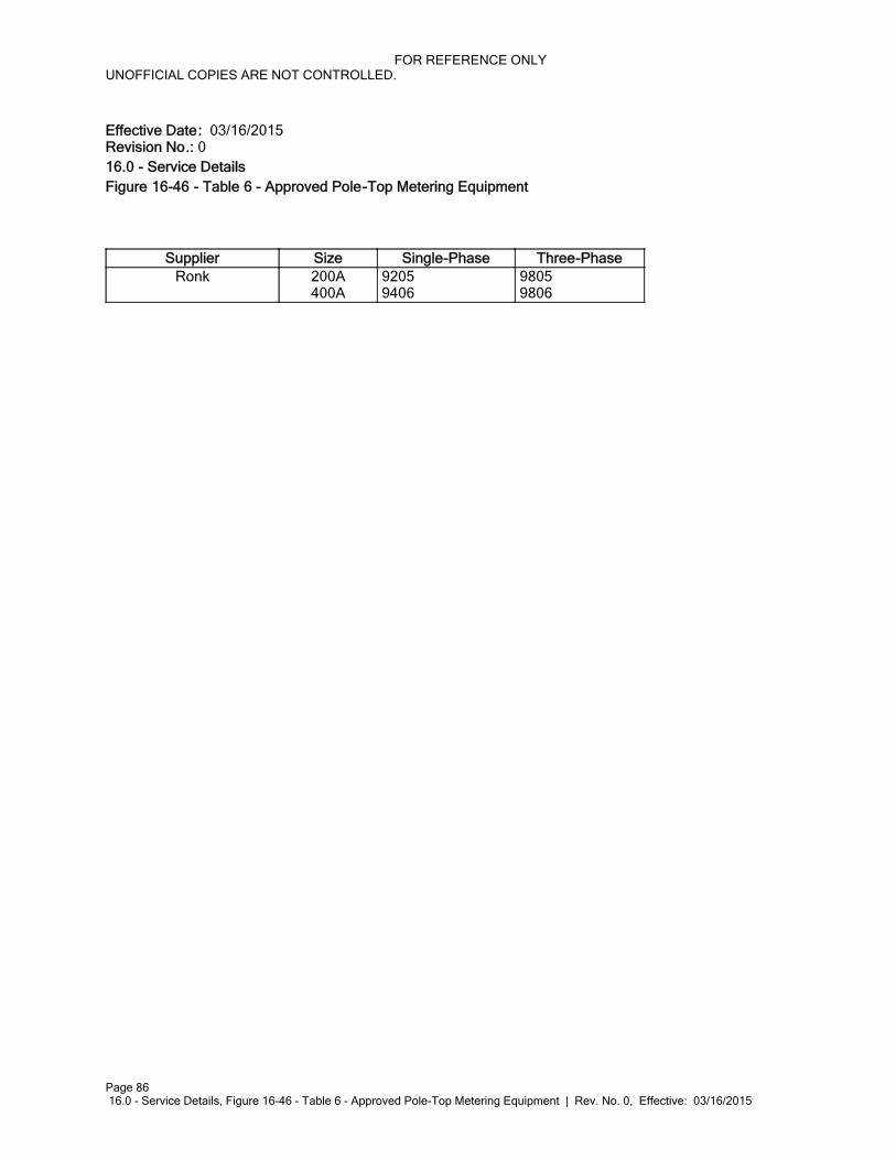
FOR REFERENCE ONLYUNOFFICIAL COPIES ARE NOT CONTROLLED.
Page 86 16.0 - Service Details, Figure 16-46 - Table 6 - Approved Pole-Top Metering Equipment | Rev. No. 0, Effective: 03/16/2015
Effective Date: 03/16/2015Revision No.: 016.0 - Service DetailsFigure 16-46 - Table 6 - Approved Pole-Top Metering Equipment
Supplier Size Single-Phase Three-PhaseRonk 200A
400A 9205 9406
9805 9806
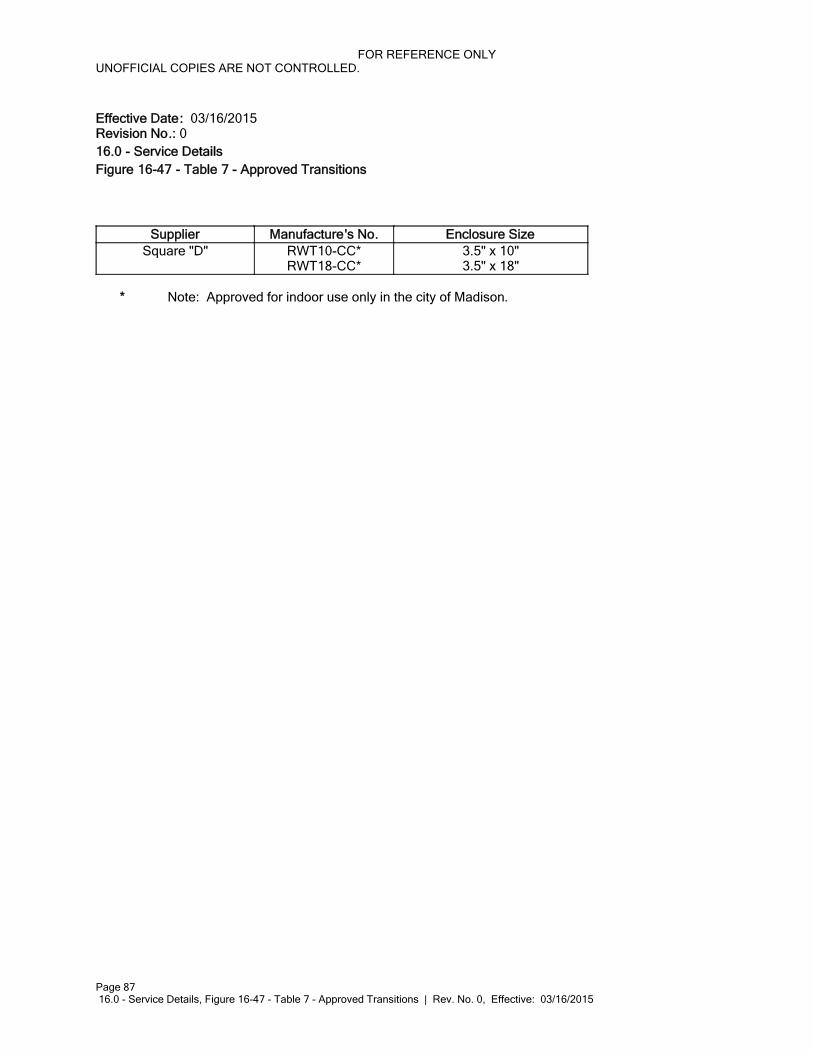
FOR REFERENCE ONLYUNOFFICIAL COPIES ARE NOT CONTROLLED.
Page 87 16.0 - Service Details, Figure 16-47 - Table 7 - Approved Transitions | Rev. No. 0, Effective: 03/16/2015
Effective Date: 03/16/2015Revision No.: 016.0 - Service DetailsFigure 16-47 - Table 7 - Approved Transitions
Supplier Manufacture's No. Enclosure SizeSquare "D" RWT10-CC*
RWT18-CC*3.5" x 10"3.5" x 18"
* Note: Approved for indoor use only in the city of Madison.
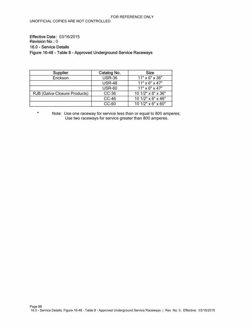
FOR REFERENCE ONLYUNOFFICIAL COPIES ARE NOT CONTROLLED.
Page 88 16.0 - Service Details, Figure 16-48 - Table 8 - Approved Underground Service Raceways | Rev. No. 0, Effective: 03/16/2015
Effective Date: 03/16/2015Revision No.: 016.0 - Service DetailsFigure 16-48 - Table 8 - Approved Underground Service Raceways
Supplier Catalog No. SizeErickson USR-36 11" x 6" x 36"
USR-48 11" x 6" x 47"USR-60 11" x 6" x 47"
RJB (Galva-Closure Products) CC-36 10 1/2" x 6" x 36"CC-46 10 1/2" x 6" x 46"CC-60 10 1/2" x 6" x 60"
* Note: Use one raceway for service less than or equal to 800 amperes; Use two raceways for service greater than 800 amperes.
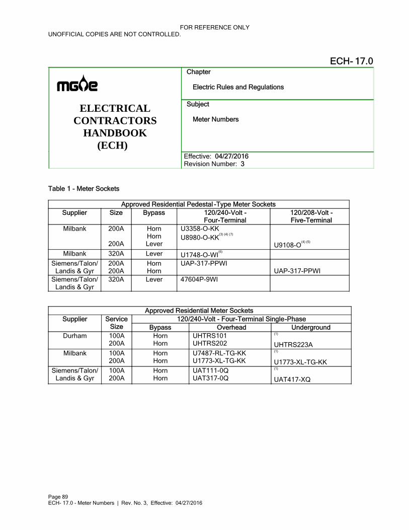
FOR REFERENCE ONLYUNOFFICIAL COPIES ARE NOT CONTROLLED.
Page 89ECH- 17.0 - Meter Numbers | Rev. No. 3, Effective: 04/27/2016
ECH- 17.0Chapter
Electric Rules and Regulations
ELECTRICAL CONTRACTORS
HANDBOOK(ECH)
Subject
Meter Numbers
Effective: 04/27/2016 Revision Number: 3
Table 1 - Meter Sockets
Approved Residential Pedestal -Type Meter SocketsSupplier Size Bypass 120/240-Volt -
Four-Terminal120/208-Volt -Five-Terminal
Milbank 200A
200A
HornHornLever
U3358-O-KKU8980-O-KK
(3) (4) (7)
U9108-O(4) (5)
Milbank 320A Lever U1748-O-WI(6)
Siemens/Talon/Landis & Gyr
200A200A
HornHorn
UAP-317-PPWIUAP-317-PPWI
Siemens/Talon/Landis & Gyr
320A Lever 47604P-9WI
Approved Residential Meter Sockets120/240-Volt - Four-Terminal Single-PhaseSupplier Service
Size Bypass Overhead UndergroundDurham 100A
200AHornHorn
UHTRS101UHTRS202
(1)
UHTRS223AMilbank 100A
200AHornHorn
U7487-RL-TG-KKU1773-XL-TG-KK
(1)
U1773-XL-TG-KKSiemens/Talon/
Landis & Gyr100A200A
HornHorn
UAT111-0QUAT317-0Q
(1)
UAT417-XQ
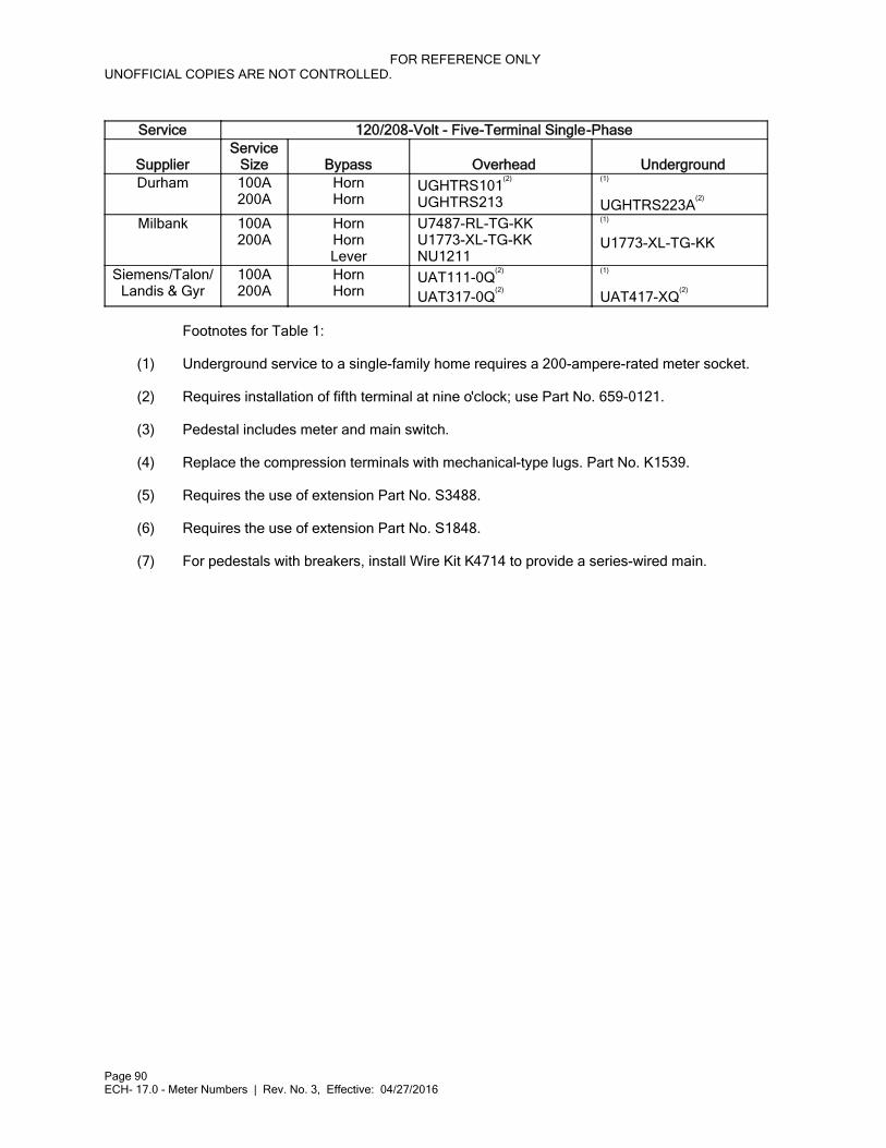
FOR REFERENCE ONLYUNOFFICIAL COPIES ARE NOT CONTROLLED.
Page 90ECH- 17.0 - Meter Numbers | Rev. No. 3, Effective: 04/27/2016
Service 120/208-Volt - Five-Terminal Single-Phase
SupplierService
Size Bypass Overhead UndergroundDurham 100A
200AHornHorn
UGHTRS101(2)
UGHTRS213
(1)
UGHTRS223A(2)
Milbank 100A200A
HornHornLever
U7487-RL-TG-KKU1773-XL-TG-KKNU1211
(1)
U1773-XL-TG-KK
Siemens/Talon/Landis & Gyr
100A200A
HornHorn
UAT111-0Q(2)
UAT317-0Q(2)
(1)
UAT417-XQ(2)
Footnotes for Table 1:
(1) Underground service to a single-family home requires a 200-ampere-rated meter socket.
(2) Requires installation of fifth terminal at nine o'clock; use Part No. 659-0121.
(3) Pedestal includes meter and main switch.
(4) Replace the compression terminals with mechanical-type lugs. Part No. K1539.
(5) Requires the use of extension Part No. S3488.
(6) Requires the use of extension Part No. S1848.
(7) For pedestals with breakers, install Wire Kit K4714 to provide a series-wired main.
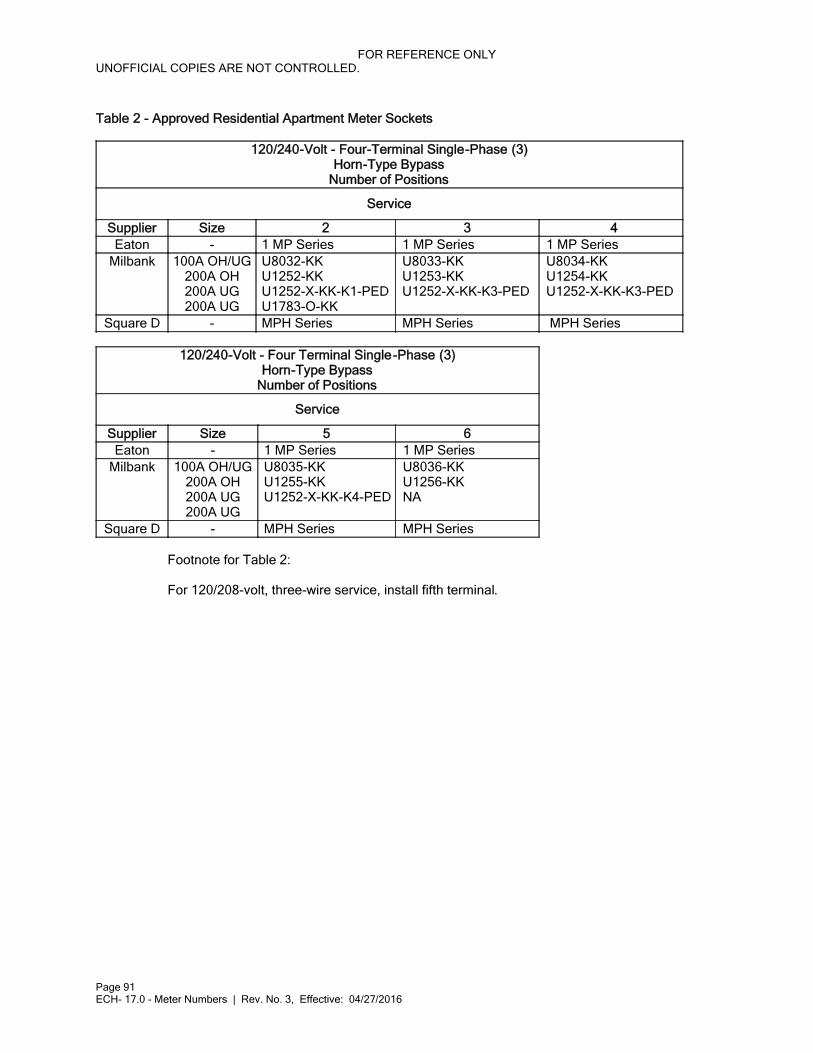
FOR REFERENCE ONLYUNOFFICIAL COPIES ARE NOT CONTROLLED.
Page 91ECH- 17.0 - Meter Numbers | Rev. No. 3, Effective: 04/27/2016
Table 2 - Approved Residential Apartment Meter Sockets
120/240-Volt - Four-Terminal Single-Phase (3)Horn-Type Bypass
Number of Positions
Service
Supplier Size 2 3 4Eaton - 1 MP Series 1 MP Series 1 MP Series
Milbank 100A OH/UG200A OH200A UG200A UG
U8032-KKU1252-KKU1252-X-KK-K1-PEDU1783-O-KK
U8033-KKU1253-KKU1252-X-KK-K3-PED
U8034-KKU1254-KKU1252-X-KK-K3-PED
Square D - MPH Series MPH Series MPH Series
120/240-Volt - Four Terminal Single-Phase (3)Horn-Type Bypass
Number of Positions
Service
Supplier Size 5 6Eaton - 1 MP Series 1 MP Series
Milbank 100A OH/UG200A OH200A UG200A UG
U8035-KKU1255-KKU1252-X-KK-K4-PED
U8036-KKU1256-KKNA
Square D - MPH Series MPH Series
Footnote for Table 2:
For 120/208-volt, three-wire service, install fifth terminal.
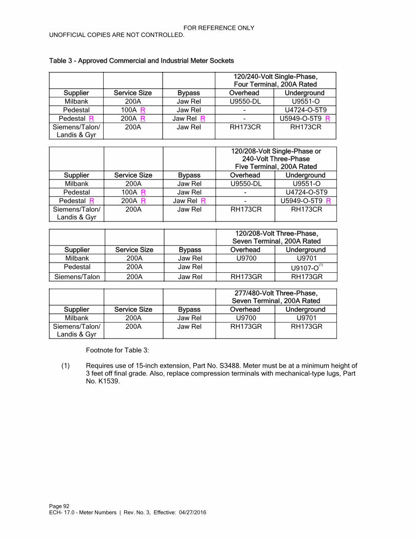
FOR REFERENCE ONLYUNOFFICIAL COPIES ARE NOT CONTROLLED.
Page 92ECH- 17.0 - Meter Numbers | Rev. No. 3, Effective: 04/27/2016
Table 3 - Approved Commercial and Industrial Meter Sockets
120/240-Volt Single-Phase,Four Terminal, 200A Rated
Supplier Service Size Bypass Overhead UndergroundMilbank 200A Jaw Rel U9550-DL U9551-OPedestal 100A R Jaw Rel - U4724-O-5T9
Pedestal R 200A R Jaw Rel R - U5949-O-5T9 RSiemens/Talon/
Landis & Gyr200A Jaw Rel RH173CR RH173CR
120/208-Volt Single-Phase or240-Volt Three-Phase
Five Terminal, 200A RatedSupplier Service Size Bypass Overhead UndergroundMilbank 200A Jaw Rel U9550-DL U9551-OPedestal 100A R Jaw Rel - U4724-O-5T9
Pedestal R 200A R Jaw Rel R - U5949-O-5T9 RSiemens/Talon/
Landis & Gyr200A Jaw Rel RH173CR RH173CR
120/208-Volt Three-Phase,Seven Terminal, 200A Rated
Supplier Service Size Bypass Overhead UndergroundMilbank 200A Jaw Rel U9700 U9701Pedestal 200A Jaw Rel U9107-O
(1)
Siemens/Talon 200A Jaw Rel RH173GR RH173GR
277/480-Volt Three-Phase,Seven Terminal, 200A Rated
Supplier Service Size Bypass Overhead UndergroundMilbank 200A Jaw Rel U9700 U9701
Siemens/Talon/Landis & Gyr
200A Jaw Rel RH173GR RH173GR
Footnote for Table 3:
(1) Requires use of 15-inch extension, Part No. S3488. Meter must be at a minimum height of3 feet off final grade. Also, replace compression terminals with mechanical-type lugs, PartNo. K1539.
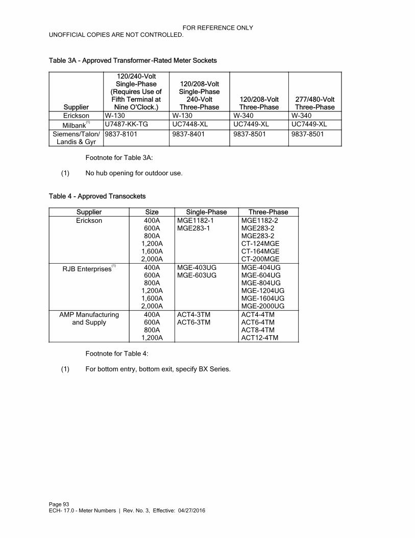
FOR REFERENCE ONLYUNOFFICIAL COPIES ARE NOT CONTROLLED.
Page 93ECH- 17.0 - Meter Numbers | Rev. No. 3, Effective: 04/27/2016
Table 3A - Approved Transformer -Rated Meter Sockets
Supplier
120/240-VoltSingle-Phase
(Requires Use ofFifth Terminal atNine O'Clock.)
120/208-VoltSingle-Phase
240-VoltThree-Phase
120/208-VoltThree-Phase
277/480-VoltThree-Phase
Erickson W-130 W-130 W-340 W-340
Milbank(1) U7487-KK-TG UC7448-XL UC7449-XL UC7449-XL
Siemens/Talon/Landis & Gyr
9837-8101 9837-8401 9837-8501 9837-8501
Footnote for Table 3A:
(1) No hub opening for outdoor use.
Table 4 - Approved Transockets
Supplier Size Single-Phase Three-PhaseErickson 400A
600A800A
1,200A1,600A2,000A
MGE1182-1MGE283-1
MGE1182-2MGE283-2MGE283-2CT-124MGECT-164MGECT-200MGE
RJB Enterprises(1) 400A
600A800A
1,200A1,600A2,000A
MGE-403UGMGE-603UG
MGE-404UGMGE-604UGMGE-804UGMGE-1204UGMGE-1604UGMGE-2000UG
AMP Manufacturingand Supply
400A600A800A
1,200A
ACT4-3TMACT6-3TM
ACT4-4TMACT6-4TMACT8-4TMACT12-4TM
Footnote for Table 4:
(1) For bottom entry, bottom exit, specify BX Series.
FOR REFERENCE ONLYUNOFFICIAL COPIES ARE NOT CONTROLLED.
Page 94ECH- 18.0 - Miscellaneous Forms | Rev. No. 0, Effective: 03/16/2015
ECH- 18.0Chapter
Electric Rules and Regulations
ELECTRICAL CONTRACTORS
HANDBOOK(ECH)
Subject
Miscellaneous Forms
Effective: 03/16/2015 Revision Number: 0
Documents listed in this section are corporate forms that can be found at www.mge.com.

FOR REFERENCE ONLYUNOFFICIAL COPIES ARE NOT CONTROLLED.
Page 95 18.0 - Miscellaneous Forms, Figure 18-1 - Application for New Service Installation, Form No. 1160 | Rev. No. 0, Effective: 03/16/20
Effective Date: 03/16/2015Revision No.: 018.0 - Miscellaneous FormsFigure 18-1 - Application for New Service Installation , Form No. 1160
Click on the link to go to Form No. 1160, Application for New Service Installation.
Click here to open the Application for New Service Installation form on MGE's website.
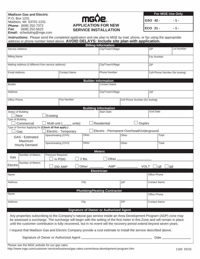
Any properties subscribing to the Company’s natural gas service inside an Area Development Program (ADP) zone may be assessed a surcharge. The surcharge will begin with the setting of the first meter in this Zone and will remain in place until the customer contribution is fully recovered, but in no event will the recovery period extend beyond seven years.
1160 02/15
GSO
ECO
42 -
21 -
- 1 -
- 1 - APPLICATION FOR NEW SERVICE INSTALLATION
Service Address City/Town/Village Lot NumberZIP
Billing Name
Mailing Address (if different from service address)
Fax Number
Contact Name
Address
Builder InformationBuilder
Office Phone Fax Number
City/Town/Village ZIP
For MGE Use Only
I request that Madison Gas and Electric Company provide a cost estimate to install the service described above.
Signature of Owner or Authorized Agent Date
Madison Gas and ElectricP.O. Box 1231Madison, WI 53701-1231Phone: (608) 252-7373Fax: (608) 252-5623
Instructions: Please send the completed application and site plan to MGE by mail, phone, or fax using the appropriateaddress or phone number listed above. AVOID DELAYS: Include site plan with application.
City/Town/Village ZIP
Building InformationStart Date
Office Phone
Address
NamePlumbing/Heating Contractor
Contact Name
Office Phone
Address
NameElectrician
Number of MetersElectric
2 lbs. ¼ PSIGPressure RequiredNumber of Meters
Gas
Meters
Multi-unit (_____ units)Commercial Duplex
Contact Name
200 AMP Other
Other
Status of BuildingNew Existing
AMP 1Ø 3ØVOLT
City
City
ZIP
ZIP
Billing Information
Email Address
Contact Name
Cell Phone Number (for texting)
GAS - Estimated Maximum
Hourly Demand
Spaceheating (CFH)
Spaceheating (CFH)
Other
Other
Other
Other
Total
Total
Signature of Owner or Authorized Agent
ResidentialType of Building
Electric - Permanent Overhead/UndergroundElectric - TemporaryGasType of Service Applying for (Check all that apply.)
Email: [email protected]
End Date
Please see the MGE website for our gas rates. http://www.mge.com/customer-service/business/gas-rates-comm/area-development-program.htm
Cell Phone Number (for texting)
Phone Number
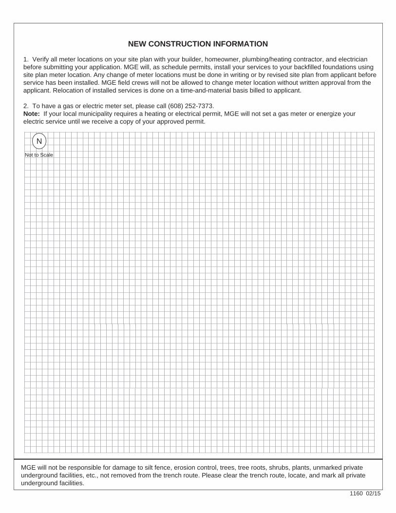
1160 02/15
NEW CONSTRUCTION INFORMATION
1. Verify all meter locations on your site plan with your builder, homeowner, plumbing/heating contractor, and electrician before submitting your application. MGE will, as schedule permits, install your services to your backfilled foundations using site plan meter location. Any change of meter locations must be done in writing or by revised site plan from applicant before service has been installed. MGE field crews will not be allowed to change meter location without written approval from the applicant. Relocation of installed services is done on a time-and-material basis billed to applicant. 2. To have a gas or electric meter set, please call (608) 252-7373. Note: If your local municipality requires a heating or electrical permit, MGE will not set a gas meter or energize your electric service until we receive a copy of your approved permit.
MGE will not be responsible for damage to silt fence, erosion control, trees, tree roots, shrubs, plants, unmarked private underground facilities, etc., not removed from the trench route. Please clear the trench route, locate, and mark all private underground facilities.
Not to Scale
N

FOR REFERENCE ONLYUNOFFICIAL COPIES ARE NOT CONTROLLED.
Page 96 18.0 - Miscellaneous Forms, Figure 18-2 - Affidavit of Electrical Work Completed, Form No. 0613 | Rev. No. 0, Effective: 03/16/201
Effective Date: 03/16/2015Revision No.: 018.0 - Miscellaneous FormsFigure 18-2 - Affidavit of Electrical Work Completed , Form No. 0613
Click on the icon to go to Form No. 0613, Affidavit of Electrical Work Completed.
Click here to open the Affidavit of Electrical Work Completed form on MGE's website.
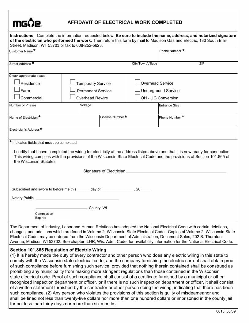
AFFIDAVIT OF ELECTRICAL WORK COMPLETED
Street Address City/Town/Village
Check appropriate boxes:
Instructions: Complete the information requested below. Be sure to include the name, address, and notarized signature of the electrician who performed the work. Then return this form by mail to Madison Gas and Electric, 133 South Blair Street, Madison, WI 53703 or fax to 608-252-5623.
Notary Public
County, WICommissionExpires
Subscribed and sworn to before me this ______ day of ________________, 20_____
Signature of Electrician
Residence
Farm
Commercial
Temporary Service
Permanent Service
Overhead Rewire
Overhead Service
Underground Service
OH - UG Conversion
Number of Phases Voltage Entrance Size
Name of Electrician Phone Number
I certify that I have completed the wiring for electricity at the address listed above and that it is now ready for connection. This wiring complies with the provisions of the Wisconsin State Electrical Code and the provisions of Section 101.865 of the Wisconsin Statutes.
0613 08/09
The Department of Industry, Labor and Human Relations has adopted the National Electrical Code with certain deletions, changes, and additions which are found in Volume 2, Wisconsin State Electrical Code. Copies of Volume 2, Wisconsin State Electrical Code, may be ordered from the Wisconsin Department of Administration, Document Sales, 202 S. Thornton Avenue, Madison WI 53702. See chapter ILHR, Wis. Adm. Code, for availability information for the National Electrical Code.
Section 101.865 Regulation of Electric Wiring (1) It is hereby made the duty of every contractor and other person who does any electric wiring in this state to comply with the Wisconsin state electrical code, and the company furnishing the electric current shall obtain proof of such compliance before furnishing such service; provided that nothing therein contained shall be construed as prohibiting any municipality from making more stringent regulations than those contained in the Wisconsin state electrical code. Proof of such compliance shall consist of a certificate furnished by a municipal or other recognized inspection department or officer, or if there is no such inspection department or officer, it shall consist of a written statement furnished by the contractor or other person doing the wiring, indicating that there has been such compliance. (2) Any person who violates the provisions of this section is guilty of misdeameanor and shall be fined not less than twenty-five dollars nor more than one hundred dollars or imprisoned in the county jail for not less than thirty days nor more than six months.
ZIP
Customer Name
Electrician's Address
Indicates fields that must be completed
*
*
Phone Number *
*
*
**License Number
*