Embed Size (px)
Citation preview

Electrical Power and Energy Systems 64 (2015) 761–770
Contents lists available at ScienceDirect
Electrical Power and Energy Systems
journal homepage: www.elsevier .com/locate / i jepes
An improved particle swarm optimization based maximum power pointtracking strategy with variable sampling time
http://dx.doi.org/10.1016/j.ijepes.2014.07.0740142-0615/� 2014 Elsevier Ltd. All rights reserved.
⇑ Corresponding author. Tel.: +60 17 378 4010.E-mail addresses: [email protected] (S.M. Mirhassani), saad@um.
edu.my (S. Mekhilef).1 Tel.: +60 37 967 6851; fax: +60 37 967 5316.
Seyed Mohsen Mirhassani a,⇑, Sayedeh Zahra Mirbagheri Golroodbari a,Sayedeh Mina Mirbagheri Golroodbari a, Saad Mekhilef b,1
a Department of Electrical of Engineering, University of Malaya, 50603 Kuala Lumpur, Malaysiab Power Electronics and Renewable Energy Research Laboratory (PEARL), Department of Electrical of Engineering, University of Malaya, 50603 Kuala Lumpur, Malaysia
a r t i c l e i n f o
Article history:Received 13 November 2013Received in revised form 21 July 2014Accepted 23 July 2014
Keywords:Maximum power point trackingParticle swarm optimizationPartially shaded conditionVariable sampling time
a b s t r a c t
This paper presents an improved maximum power point tracking (MPPT) strategy for photovoltaic (PV)systems based on particle swarm optimization (PSO). The capability of the PSO algorithm to cope withpartially shaded conditions (PSCs) is the primary motivation of this research. Unlike conventionalPSO-based MPPT systems, a variable sampling time strategy (VSTS) based on the investigation of thedynamic behavior of converter current is deployed to increase system tracking time. The performanceof the proposed system is evaluated using MATLAB simulation and experimentation, in which a digitalsignal controller is used to implement the proposed algorithm on a real boost converter connected toa PV simulator. The main advantage of the proposed algorithm is fast and accurate performance underdifferent conditions, including PSCs.
� 2014 Elsevier Ltd. All rights reserved.
Introduction
The increasing demand for energy and the limited capacity offossil fuel resources have motivated numerous studies on alterna-tive renewable energy resources in recent decades. Among the dif-ferent renewable energy resources, photovoltaic (PV) solar energy,particularly in a grid-connected configuration, has attracted con-siderable interests because of its availability, low maintenancedemand, and environment friendliness. Despite all its benefits,the high investment cost required by this technology makesextracting a large amount of available power from PV panels nec-essary. As a result, maximum power point tracking (MPPT) strate-gies should be deployed to ensure the tracking of the maximumpower point (MPP) of nonlinear PV characteristics. The major chal-lenges of MPPT lie in its dependence on the environmental param-eters of the PV curve (i.e., temperature and insolation dependence)and in the local peaks created on the PV curve as a result of par-tially shaded PV panels (Fig. 2c) [1,2]. Partially shaded condition(PSC) will be discussed in the next section.
Several MPPT strategies have been suggested in literature. Thesestrategies can be classified into off-line and on-line approaches.
Off-line approaches estimate the location of the MPP based on theopen circuit voltage or short circuit current of the panel and onthe standard test information provided by the manufacturer [3,4].However, the nonlinear dependence of PV characteristics on celltemperature and solar insolation is a major road block against thefunctionality of these approaches. Such dependence results in sig-nificant errors in MPPT in some situations. On-line approaches focuson the information being acquired while energy is transferred fromthe PV, such that any estimation based on standard test informationwill be unnecessary, and the controller easily adapts itself to anyvariation of the aforementioned parameters. Among the on-lineapproaches, perturb and observe (P&O) [5–7] and incremental con-ductance (IC) [8–10] are two well-known MPPT strategies. In addi-tion to imposing an inevitable tradeoff between tracking speed andfluctuation of extracted power, these strategies cannot differentiatebetween global and local MPP when PSC causes a multi-peak P–V,thus resulting in the tracking of a local peak that may not be the glo-bal MPP. Furthermore, typical P&O strategies suffer from the loss ofcorrect direction of the MPP location in case of rapid changes in solarinsolation [11]. From the control perspective, MPPT strategies canalso be classified into direct [e.g., hill climbing (HC)] and indirectapproaches (e.g., P&O and IC). Direct approaches take control ofthe duty cycle of the converter switch, whereas the output of theindirect algorithm is a reference value for the PV voltage or current.In this case, an additional control loop [i.e., proportional integralderivative (PID) controller] is needed to adapt the duty cycle to
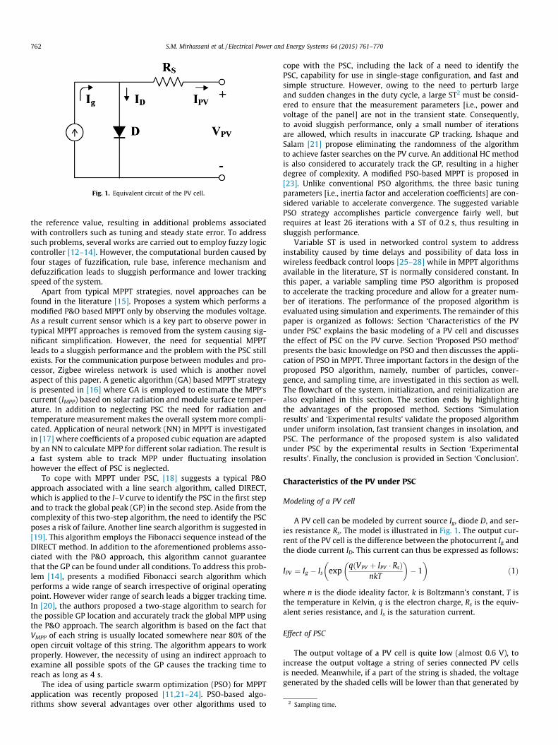
Fig. 1. Equivalent circuit of the PV cell.
2 Sampling time.
762 S.M. Mirhassani et al. / Electrical Power and Energy Systems 64 (2015) 761–770
the reference value, resulting in additional problems associatedwith controllers such as tuning and steady state error. To addresssuch problems, several works are carried out to employ fuzzy logiccontroller [12–14]. However, the computational burden caused byfour stages of fuzzification, rule base, inference mechanism anddefuzzification leads to sluggish performance and lower trackingspeed of the system.
Apart from typical MPPT strategies, novel approaches can befound in the literature [15]. Proposes a system which performs amodified P&O based MPPT only by observing the modules voltage.As a result current sensor which is a key part to observe power intypical MPPT approaches is removed from the system causing sig-nificant simplification. However, the need for sequential MPPTleads to a sluggish performance and the problem with the PSC stillexists. For the communication purpose between modules and pro-cessor, Zigbee wireless network is used which is another novelaspect of this paper. A genetic algorithm (GA) based MPPT strategyis presented in [16] where GA is employed to estimate the MPP’scurrent (IMPP) based on solar radiation and module surface temper-ature. In addition to neglecting PSC the need for radiation andtemperature measurement makes the overall system more compli-cated. Application of neural network (NN) in MPPT is investigatedin [17] where coefficients of a proposed cubic equation are adaptedby an NN to calculate MPP for different solar radiation. The result isa fast system able to track MPP under fluctuating insolationhowever the effect of PSC is neglected.
To cope with MPPT under PSC, [18] suggests a typical P&Oapproach associated with a line search algorithm, called DIRECT,which is applied to the I–V curve to identify the PSC in the first stepand to track the global peak (GP) in the second step. Aside from thecomplexity of this two-step algorithm, the need to identify the PSCposes a risk of failure. Another line search algorithm is suggested in[19]. This algorithm employs the Fibonacci sequence instead of theDIRECT method. In addition to the aforementioned problems asso-ciated with the P&O approach, this algorithm cannot guaranteethat the GP can be found under all conditions. To address this prob-lem [14], presents a modified Fibonacci search algorithm whichperforms a wide range of search irrespective of original operatingpoint. However wider range of search leads a bigger tracking time.In [20], the authors proposed a two-stage algorithm to search forthe possible GP location and accurately track the global MPP usingthe P&O approach. The search algorithm is based on the fact thatVMPP of each string is usually located somewhere near 80% of theopen circuit voltage of this string. The algorithm appears to workproperly. However, the necessity of using an indirect approach toexamine all possible spots of the GP causes the tracking time toreach as long as 4 s.
The idea of using particle swarm optimization (PSO) for MPPTapplication was recently proposed [11,21–24]. PSO-based algo-rithms show several advantages over other algorithms used to
cope with the PSC, including the lack of a need to identify thePSC, capability for use in single-stage configuration, and fast andsimple structure. However, owing to the need to perturb largeand sudden changes in the duty cycle, a large ST2 must be consid-ered to ensure that the measurement parameters [i.e., power andvoltage of the panel] are not in the transient state. Consequently,to avoid sluggish performance, only a small number of iterationsare allowed, which results in inaccurate GP tracking. Ishaque andSalam [21] propose eliminating the randomness of the algorithmto achieve faster searches on the PV curve. An additional HC methodis also considered to accurately track the GP, resulting in a higherdegree of complexity. A modified PSO-based MPPT is proposed in[23]. Unlike conventional PSO algorithms, the three basic tuningparameters [i.e., inertia factor and acceleration coefficients] are con-sidered variable to accelerate convergence. The suggested variablePSO strategy accomplishes particle convergence fairly well, butrequires at least 26 iterations with a ST of 0.2 s, thus resulting insluggish performance.
Variable ST is used in networked control system to addressinstability caused by time delays and possibility of data loss inwireless feedback control loops [25–28] while in MPPT algorithmsavailable in the literature, ST is normally considered constant. Inthis paper, a variable sampling time PSO algorithm is proposedto accelerate the tracking procedure and allow for a greater num-ber of iterations. The performance of the proposed algorithm isevaluated using simulation and experiments. The remainder of thispaper is organized as follows: Section ‘Characteristics of the PVunder PSC’ explains the basic modeling of a PV cell and discussesthe effect of PSC on the PV curve. Section ‘Proposed PSO method’presents the basic knowledge on PSO and then discusses the appli-cation of PSO in MPPT. Three important factors in the design of theproposed PSO algorithm, namely, number of particles, conver-gence, and sampling time, are investigated in this section as well.The flowchart of the system, initialization, and reinitialization arealso explained in this section. The section ends by highlightingthe advantages of the proposed method. Sections ‘Simulationresults’ and ‘Experimental results’ validate the proposed algorithmunder uniform insolation, fast transient changes in insolation, andPSC. The performance of the proposed system is also validatedunder PSC by the experimental results in Section ‘Experimentalresults’. Finally, the conclusion is provided in Section ‘Conclusion’.
Characteristics of the PV under PSC
Modeling of a PV cell
A PV cell can be modeled by current source Ig, diode D, and ser-ies resistance Rs. The model is illustrated in Fig. 1. The output cur-rent of the PV cell is the difference between the photocurrent Ig andthe diode current ID. This current can thus be expressed as follows:
IPV ¼ Ig � Is expq VPV þ IPV � Rsð Þ
nkT
� �� 1
� �ð1Þ
where n is the diode ideality factor, k is Boltzmann’s constant, T isthe temperature in Kelvin, q is the electron charge, Rs is the equiv-alent series resistance, and Is is the saturation current.
Effect of PSC
The output voltage of a PV cell is quite low (almost 0.6 V), toincrease the output voltage a string of series connected PV cellsis needed. Meanwhile, if a part of the string is shaded, the voltagegenerated by the shaded cells will be lower than that generated by
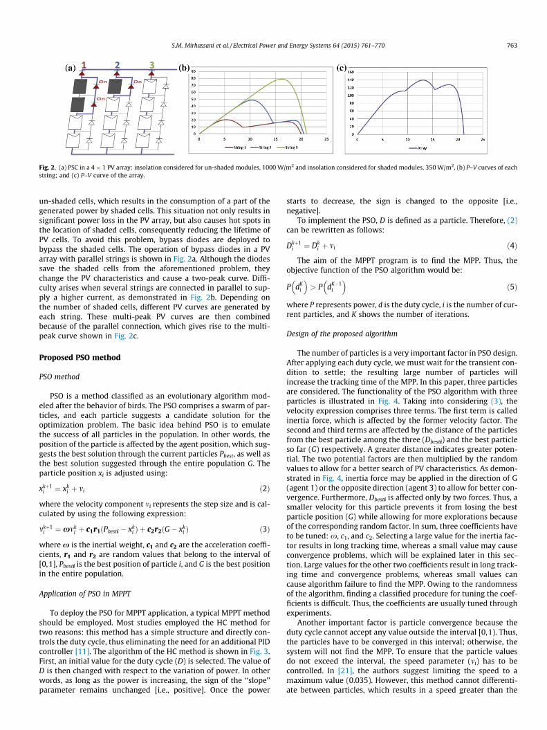
Fig. 2. (a) PSC in a 4 � 1 PV array: insolation considered for un-shaded modules, 1000 W/m2 and insolation considered for shaded modules, 350 W/m2, (b) P–V curves of eachstring; and (c) P–V curve of the array.
S.M. Mirhassani et al. / Electrical Power and Energy Systems 64 (2015) 761–770 763
un-shaded cells, which results in the consumption of a part of thegenerated power by shaded cells. This situation not only results insignificant power loss in the PV array, but also causes hot spots inthe location of shaded cells, consequently reducing the lifetime ofPV cells. To avoid this problem, bypass diodes are deployed tobypass the shaded cells. The operation of bypass diodes in a PVarray with parallel strings is shown in Fig. 2a. Although the diodessave the shaded cells from the aforementioned problem, theychange the PV characteristics and cause a two-peak curve. Diffi-culty arises when several strings are connected in parallel to sup-ply a higher current, as demonstrated in Fig. 2b. Depending onthe number of shaded cells, different PV curves are generated byeach string. These multi-peak PV curves are then combinedbecause of the parallel connection, which gives rise to the multi-peak curve shown in Fig. 2c.
Proposed PSO method
PSO method
PSO is a method classified as an evolutionary algorithm mod-eled after the behavior of birds. The PSO comprises a swarm of par-ticles, and each particle suggests a candidate solution for theoptimization problem. The basic idea behind PSO is to emulatethe success of all particles in the population. In other words, theposition of the particle is affected by the agent position, which sug-gests the best solution through the current particles Pbest, as well asthe best solution suggested through the entire population G. Theparticle position xi is adjusted using:
xkþ1i ¼ xk
i þ mi ð2Þ
where the velocity component mi represents the step size and is cal-culated by using the following expression:
mkþ1i ¼ xmk
i þ c1r1ðPbesti � xki Þ þ c2r2ðG� xk
i Þ ð3Þ
where x is the inertial weight, c1 and c2 are the acceleration coeffi-cients, r1 and r2 are random values that belong to the interval of[0,1], Pbesti is the best position of particle i, and G is the best positionin the entire population.
Application of PSO in MPPT
To deploy the PSO for MPPT application, a typical MPPT methodshould be employed. Most studies employed the HC method fortwo reasons: this method has a simple structure and directly con-trols the duty cycle, thus eliminating the need for an additional PIDcontroller [11]. The algorithm of the HC method is shown in Fig. 3.First, an initial value for the duty cycle (D) is selected. The value ofD is then changed with respect to the variation of power. In otherwords, as long as the power is increasing, the sign of the ‘‘slope’’parameter remains unchanged [i.e., positive]. Once the power
starts to decrease, the sign is changed to the opposite [i.e.,negative].
To implement the PSO, D is defined as a particle. Therefore, (2)can be rewritten as follows:
Dkþ1i ¼ Dk
i þ mi ð4Þ
The aim of the MPPT program is to find the MPP. Thus, theobjective function of the PSO algorithm would be:
P dKi
� �> P dK�1
i
� �ð5Þ
where P represents power, d is the duty cycle, i is the number of cur-rent particles, and K shows the number of iterations.
Design of the proposed algorithm
The number of particles is a very important factor in PSO design.After applying each duty cycle, we must wait for the transient con-dition to settle; the resulting large number of particles willincrease the tracking time of the MPP. In this paper, three particlesare considered. The functionality of the PSO algorithm with threeparticles is illustrated in Fig. 4. Taking into considering (3), thevelocity expression comprises three terms. The first term is calledinertia force, which is affected by the former velocity factor. Thesecond and third terms are affected by the distance of the particlesfrom the best particle among the three (Dbesti) and the best particleso far (G) respectively. A greater distance indicates greater poten-tial. The two potential factors are then multiplied by the randomvalues to allow for a better search of PV characteristics. As demon-strated in Fig. 4, inertia force may be applied in the direction of G(agent 1) or the opposite direction (agent 3) to allow for better con-vergence. Furthermore, Dbesti is affected only by two forces. Thus, asmaller velocity for this particle prevents it from losing the bestparticle position (G) while allowing for more explorations becauseof the corresponding random factor. In sum, three coefficients haveto be tuned: x, c1, and c2. Selecting a large value for the inertia fac-tor results in long tracking time, whereas a small value may causeconvergence problems, which will be explained later in this sec-tion. Large values for the other two coefficients result in long track-ing time and convergence problems, whereas small values cancause algorithm failure to find the MPP. Owing to the randomnessof the algorithm, finding a classified procedure for tuning the coef-ficients is difficult. Thus, the coefficients are usually tuned throughexperiments.
Another important factor is particle convergence because theduty cycle cannot accept any value outside the interval [0,1). Thus,the particles have to be converged in this interval; otherwise, thesystem will not find the MPP. To ensure that the particle valuesdo not exceed the interval, the speed parameter (mi) has to becontrolled. In [21], the authors suggest limiting the speed to amaximum value (0.035). However, this method cannot differenti-ate between particles, which results in a speed greater than the

Fig. 3. HC algorithm.
Fig. 4. PSO algorithm with three particles (a) at the middle of the execution time and (b) at the end of the execution time.
764 S.M. Mirhassani et al. / Electrical Power and Energy Systems 64 (2015) 761–770
maximum value and causes longer tracking time. In this study, theinverse tangent function is used to retain the speed within a safemargin. While allowing for the implementation of greater speedterms with respect to the distance of the particle to the desiredvalue, this function ensures that the value generated by the ran-dom coefficients is within the interval. The speed expression isdescribed below. To reduce computation time, the function canbe estimated by a lookup table.
mkþ1i ¼ 2
parctanðxmk
i þ c1r1ðDbesti � Dki Þ þ c2r2ðG� Dk
i ÞÞ ð6Þ
where Dbesti is the duty cycle that results in the maximum poweramong the three particles, and G is the duty cycle that results inthe maximum power through the entire population.
The last factor to be considered is sampling time. After applyingeach particle, the controller should wait for the power to settle.Thus, after applying each duty cycle, a delay occurs during the exe-cution of the MPP program. Most authors considered a FSTS3
3 Fixed Sampling Time Strategy.
[11,21–24]. However, the settling time of the system varies withthe step size. For instance, the settling time of the power after per-turbing 20% change in the duty cycle is not the same as the valuefor perturbing only 5% change. By contrast, as the program loop exe-cutes, the particles become close to one another (Fig. 4b), which indi-cates that applying a variable sampling time strategy (VSTS) canaccelerate the tracking procedure significantly.
State space model of the system
To study the effect of step size on settling time, the state space(SS) model of the system will be derived in this section. The sche-matic of the system under study is demonstrated in Fig. 5. Toderive a linearized SS model, the PV is considered as a constantindependent current source. The SS model can be derived easilyby applying KVL in loops 1 and 2 and KCL in nodes 1 and 2 inthe two following instances:
� The switch is on and the diode is off (Ton)� The switch is off and the diode is on (Toff)
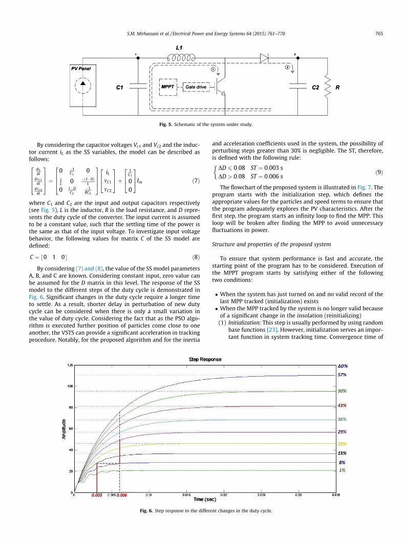
Fig. 5. Schematic of the system under study.
S.M. Mirhassani et al. / Electrical Power and Energy Systems 64 (2015) 761–770 765
By considering the capacitor voltages Vc1 and Vc2 and the induc-tor current iL as the SS variables, the model can be described asfollows:
diLdt
dmC1dt
dmC2dt
2664
3775 ¼
0 �1C1
01L 0 �ð1�DÞ
L
0 1�DC2
�1RC2
2664
3775
iL
mC1
mC2
264
375þ
1C1
00
264
375Iin ð7Þ
where C1 and C2 are the input and output capacitors respectively(see Fig. 5), L is the inductor, R is the load resistance, and D repre-sents the duty cycle of the converter. The input current is assumedto be a constant value, such that the settling time of the power isthe same as that of the input voltage. To investigate input voltagebehavior, the following values for matrix C of the SS model aredefined:
C ¼ ½0 1 0 � ð8Þ
By considering (7) and (8), the value of the SS model parametersA, B, and C are known. Considering constant input, zero value canbe assumed for the D matrix in this level. The response of the SSmodel to the different steps of the duty cycle is demonstrated inFig. 6. Significant changes in the duty cycle require a longer timeto settle. As a result, shorter delay in perturbation of new dutycycle can be considered when there is only a small variation inthe value of duty cycle. Considering the fact that as the PSO algo-rithm is executed further position of particles come close to oneanother, the VSTS can provide a significant acceleration in trackingprocedure. Notably, for the proposed algorithm and for the inertia
Fig. 6. Step response to the differe
and acceleration coefficients used in the system, the possibility ofperturbing steps greater than 30% is negligible. The ST, therefore,is defined with the following rule:
DD 6 0:08 ST ¼ 0:003 sDD > 0:08 ST ¼ 0:006 s
�ð9Þ
The flowchart of the proposed system is illustrated in Fig. 7. Theprogram starts with the initialization step, which defines theappropriate values for the particles and speed terms to ensure thatthe program adequately explores the PV characteristics. After thefirst step, the program starts an infinity loop to find the MPP. Thisloop will be broken after finding the MPP to avoid unnecessaryfluctuations in power.
Structure and properties of the proposed system
To ensure that system performance is fast and accurate, thestarting point of the program has to be considered. Execution ofthe MPPT program starts by satisfying either of the followingtwo conditions:
� When the system has just turned on and no valid record of thelast MPP tracked (initialization) exists� When the MPP tracked by the system is no longer valid because
of a significant change in the insolation (reinitializing)(1) Initialization: This step is usually performed by using random
base functions [23]. However, initialization serves an impor-tant function in system tracking time. Convergence time of
nt changes in the duty cycle.
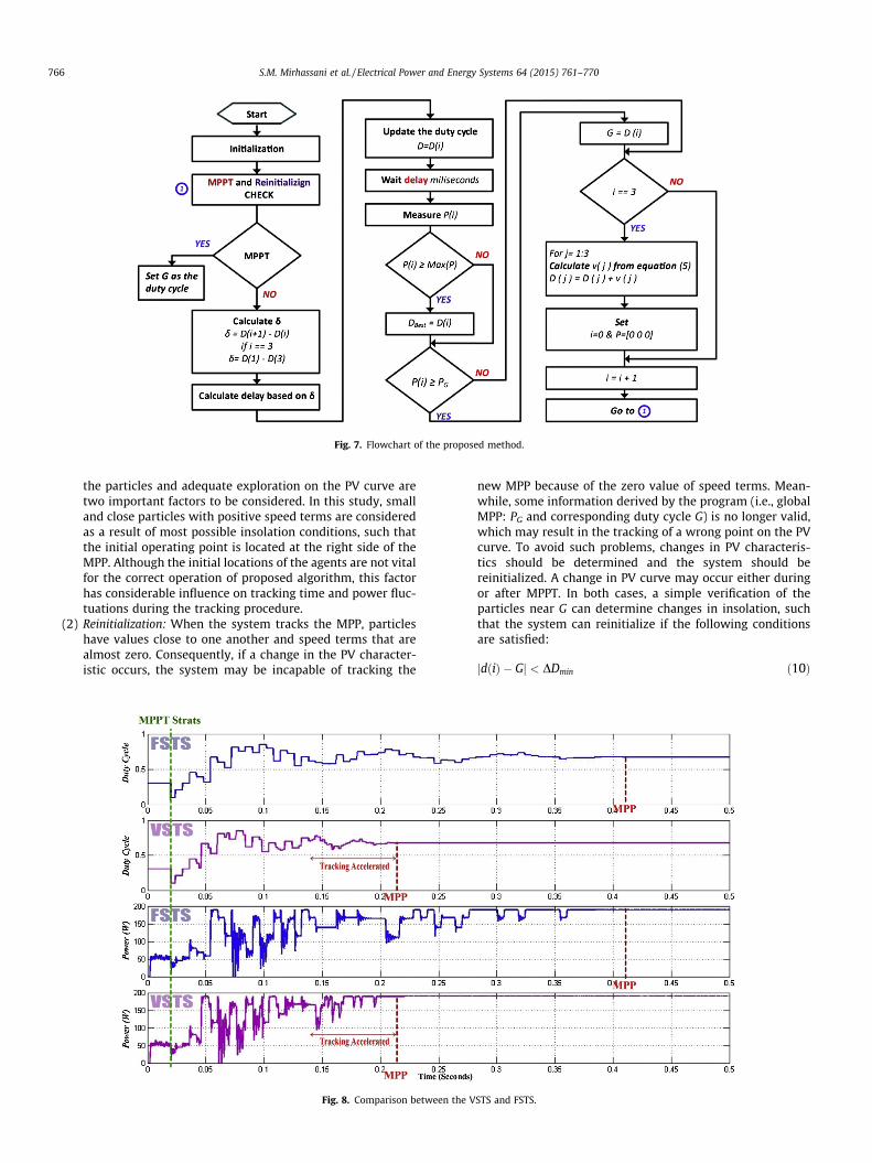
Fig. 7. Flowchart of the proposed method.
766 S.M. Mirhassani et al. / Electrical Power and Energy Systems 64 (2015) 761–770
the particles and adequate exploration on the PV curve aretwo important factors to be considered. In this study, smalland close particles with positive speed terms are consideredas a result of most possible insolation conditions, such thatthe initial operating point is located at the right side of theMPP. Although the initial locations of the agents are not vitalfor the correct operation of proposed algorithm, this factorhas considerable influence on tracking time and power fluc-tuations during the tracking procedure.
(2) Reinitialization: When the system tracks the MPP, particleshave values close to one another and speed terms that arealmost zero. Consequently, if a change in the PV character-istic occurs, the system may be incapable of tracking the
Fig. 8. Comparison betwee
new MPP because of the zero value of speed terms. Mean-while, some information derived by the program (i.e., globalMPP: PG and corresponding duty cycle G) is no longer valid,which may result in the tracking of a wrong point on the PVcurve. To avoid such problems, changes in PV characteris-tics should be determined and the system should bereinitialized. A change in PV curve may occur either duringor after MPPT. In both cases, a simple verification of theparticles near G can determine changes in insolation, suchthat the system can reinitialize if the following conditionsare satisfied:
n the V
jdðiÞ � Gj < DDmin ð10Þ
STS and FSTS.
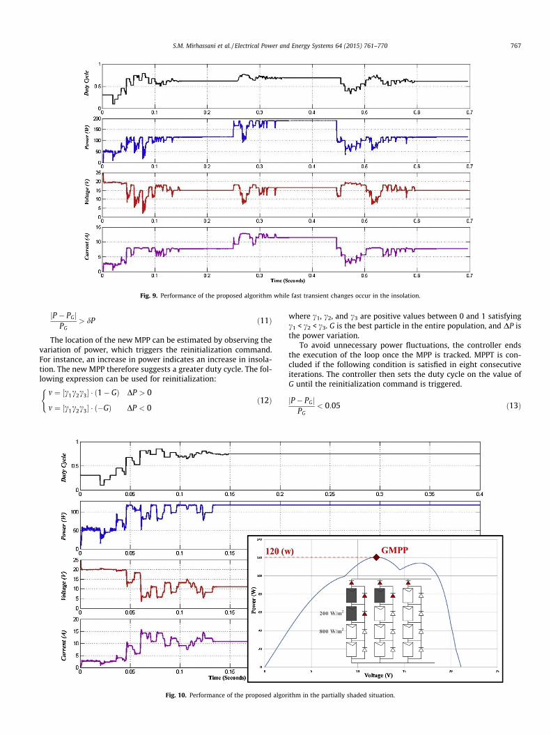
Fig. 9. Performance of the proposed algorithm while fast transient changes occur in the insolation.
S.M. Mirhassani et al. / Electrical Power and Energy Systems 64 (2015) 761–770 767
jP � PGjPG
> dP ð11Þ
The location of the new MPP can be estimated by observing thevariation of power, which triggers the reinitialization command.For instance, an increase in power indicates an increase in insola-tion. The new MPP therefore suggests a greater duty cycle. The fol-lowing expression can be used for reinitialization:
m ¼ ½c1c2c3� � ð1� GÞ DP > 0
m ¼ ½c1c2c3� � ð�GÞ DP < 0
(ð12Þ
Fig. 10. Performance of the proposed algor
where c1, c2, and c3 are positive values between 0 and 1 satisfyingc1 < c2 < c3. G is the best particle in the entire population, and DP isthe power variation.
To avoid unnecessary power fluctuations, the controller endsthe execution of the loop once the MPP is tracked. MPPT is con-cluded if the following condition is satisfied in eight consecutiveiterations. The controller then sets the duty cycle on the value ofG until the reinitialization command is triggered.
jP � PGjPG
< 0:05 ð13Þ
ithm in the partially shaded situation.
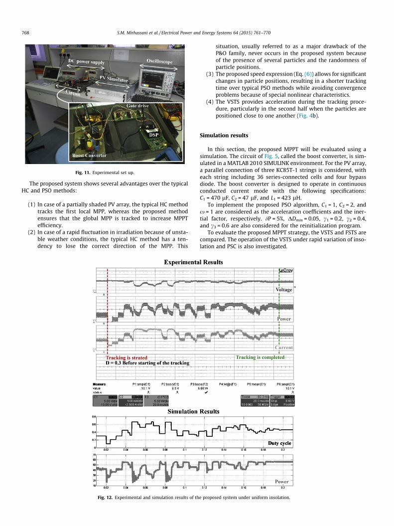
Fig. 11. Experimental set up.
768 S.M. Mirhassani et al. / Electrical Power and Energy Systems 64 (2015) 761–770
The proposed system shows several advantages over the typicalHC and PSO methods:
(1) In case of a partially shaded PV array, the typical HC methodtracks the first local MPP, whereas the proposed methodensures that the global MPP is tracked to increase MPPTefficiency.
(2) In case of a rapid fluctuation in irradiation because of unsta-ble weather conditions, the typical HC method has a ten-dency to lose the correct direction of the MPP. This
Fig. 12. Experimental and simulation results of th
situation, usually referred to as a major drawback of theP&O family, never occurs in the proposed system becauseof the presence of several particles and the randomness ofparticle positions.
(3) The proposed speed expression (Eq. (6)) allows for significantchanges in particle positions, resulting in a shorter trackingtime over typical PSO methods while avoiding convergenceproblems because of special nonlinear characteristics.
(4) The VSTS provides acceleration during the tracking proce-dure, particularly in the second half when the particles arepositioned close to one another (Fig. 4b).
Simulation results
In this section, the proposed MPPT will be evaluated using asimulation. The circuit of Fig. 5, called the boost converter, is sim-ulated in a MATLAB 2010 SIMULINK environment. For the PV array,a parallel connection of three KC85T-1 strings is considered, witheach string including 36 series-connected cells and four bypassdiode. The boost converter is designed to operate in continuousconducted current mode with the following specifications:C1 = 470 lF, C2 = 47 lF, and L1 = 423 lH.
To implement the proposed PSO algorithm, C1 = 1, C2 = 2, andx = 1 are considered as the acceleration coefficients and the iner-tial factor, respectively. dP = 5%, DDmin = 0.05, c1 = 0.2, c2 = 0.4,and c3 = 0.6 are also considered for the reinitialization program.
To evaluate the proposed MPPT strategy, the VSTS and FSTS arecompared. The operation of the VSTS under rapid variation of inso-lation and PSC is also investigated.
e proposed system under uniform insolation.
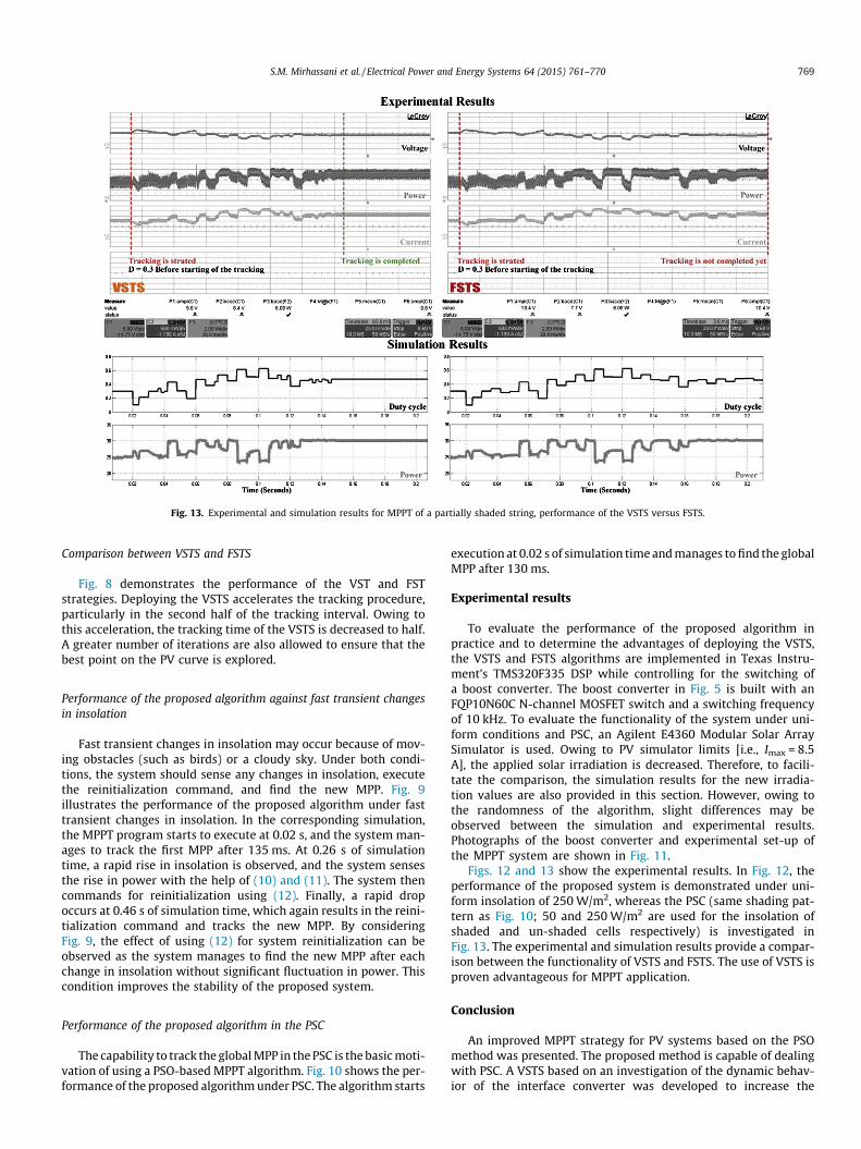
Fig. 13. Experimental and simulation results for MPPT of a partially shaded string, performance of the VSTS versus FSTS.
S.M. Mirhassani et al. / Electrical Power and Energy Systems 64 (2015) 761–770 769
Comparison between VSTS and FSTS
Fig. 8 demonstrates the performance of the VST and FSTstrategies. Deploying the VSTS accelerates the tracking procedure,particularly in the second half of the tracking interval. Owing tothis acceleration, the tracking time of the VSTS is decreased to half.A greater number of iterations are also allowed to ensure that thebest point on the PV curve is explored.
Performance of the proposed algorithm against fast transient changesin insolation
Fast transient changes in insolation may occur because of mov-ing obstacles (such as birds) or a cloudy sky. Under both condi-tions, the system should sense any changes in insolation, executethe reinitialization command, and find the new MPP. Fig. 9illustrates the performance of the proposed algorithm under fasttransient changes in insolation. In the corresponding simulation,the MPPT program starts to execute at 0.02 s, and the system man-ages to track the first MPP after 135 ms. At 0.26 s of simulationtime, a rapid rise in insolation is observed, and the system sensesthe rise in power with the help of (10) and (11). The system thencommands for reinitialization using (12). Finally, a rapid dropoccurs at 0.46 s of simulation time, which again results in the reini-tialization command and tracks the new MPP. By consideringFig. 9, the effect of using (12) for system reinitialization can beobserved as the system manages to find the new MPP after eachchange in insolation without significant fluctuation in power. Thiscondition improves the stability of the proposed system.
Performance of the proposed algorithm in the PSC
The capability to track the global MPP in the PSC is the basic moti-vation of using a PSO-based MPPT algorithm. Fig. 10 shows the per-formance of the proposed algorithm under PSC. The algorithm starts
execution at 0.02 s of simulation time and manages to find the globalMPP after 130 ms.
Experimental results
To evaluate the performance of the proposed algorithm inpractice and to determine the advantages of deploying the VSTS,the VSTS and FSTS algorithms are implemented in Texas Instru-ment’s TMS320F335 DSP while controlling for the switching ofa boost converter. The boost converter in Fig. 5 is built with anFQP10N60C N-channel MOSFET switch and a switching frequencyof 10 kHz. To evaluate the functionality of the system under uni-form conditions and PSC, an Agilent E4360 Modular Solar ArraySimulator is used. Owing to PV simulator limits [i.e., Imax = 8.5A], the applied solar irradiation is decreased. Therefore, to facili-tate the comparison, the simulation results for the new irradia-tion values are also provided in this section. However, owing tothe randomness of the algorithm, slight differences may beobserved between the simulation and experimental results.Photographs of the boost converter and experimental set-up ofthe MPPT system are shown in Fig. 11.
Figs. 12 and 13 show the experimental results. In Fig. 12, theperformance of the proposed system is demonstrated under uni-form insolation of 250 W/m2, whereas the PSC (same shading pat-tern as Fig. 10; 50 and 250 W/m2 are used for the insolation ofshaded and un-shaded cells respectively) is investigated inFig. 13. The experimental and simulation results provide a compar-ison between the functionality of VSTS and FSTS. The use of VSTS isproven advantageous for MPPT application.
Conclusion
An improved MPPT strategy for PV systems based on the PSOmethod was presented. The proposed method is capable of dealingwith PSC. A VSTS based on an investigation of the dynamic behav-ior of the interface converter was developed to increase the

770 S.M. Mirhassani et al. / Electrical Power and Energy Systems 64 (2015) 761–770
accuracy and improve the tracking time of the system. The initial-ization and reinitialization steps of the proposed algorithm werestudied, and the advantages of this strategy over conventionalPSO-based methods and other MPPT strategies were highlighted.The performance of the proposed system was validated using MAT-LAB simulation and an experimentation system comprising a digi-tal signal controller, a boost converter, and a PV simulator. Fast andaccurate performance under different conditions, including PSC,was proven as the main advantage of the proposed algorithm.
Acknowledgement
The authors would like to thank Ministry of Higher Education ofMalaysia and University of Malaya for providing financial supportunder the research Grant No: UM.C/HIR/MOHE/ENG/D000024
References
[1] Drif M, Perez P, Aguilera J, Aguilar J. A new estimation method of irradiance ona partially shaded PV generator in grid-connected photovoltaic systems.Renew Energy 2008;33:2048–56.
[2] Seyedmahmoudian M, Mekhilef S, Rahmani R, Yusof R, Renani ET. Analyticalmodeling of partially shaded photovoltaic systems. Energies 2013;6:128–44.
[3] Masoum MA, Dehbonei H, Fuchs EF. Theoretical and experimental analyses ofphotovoltaic systems with voltage and current-based maximum power-pointtracking. IEEE Trans Energy Convers 2002;17:514–22.
[4] Noguchi T, Togashi S, Nakamoto R. Short-current pulse-based maximum-power-point tracking method for multiple photovoltaic-and-converter modulesystem. IEEE Trans Ind Electron 2002;49:217–23.
[5] Tafticht T, Agbossou K, Doumbia M, Chériti A. An improved maximum powerpoint tracking method for photovoltaic systems. Renew Energy2008;33:1508–16.
[6] Mellit A, Rezzouk H, Messai A, Medjahed B. FPGA-based real timeimplementation of MPPT-controller for photovoltaic systems. Renew Energy2011;36:1652–61.
[7] Palizban O, Mekhilef S. Modeling and control of photovoltaic panels baseperturbation and observation MPPT method. In: Control system, computingand engineering (ICCSCE), 2011 IEEE international conference, 2011. p.393–8.
[8] Safari A, Mekhilef S. Simulation and hardware implementation of incrementalconductance MPPT with direct control method using Cuk converter. IEEE TransInd Electron 2011;58:1154–61.
[9] Tey KS, Mekhilef S. Modified incremental conductance MPPT algorithm tomitigate inaccurate responses under fast-changing solar irradiation level. SolEnergy 2014;101:333–42.
[10] Mirbagheri SZ, Mekhilef S, Mirhassani SM. MPPT with Inc., Cond method usingconventional interleaved boost converter. Energy Proc 2013;42:24–32.
[11] Ishaque K, Salam Z, Amjad M, Mekhilef S. An improved particle swarmoptimization (PSO)–Based MPPT for PV with reduced steady-state oscillation.IEEE Trans Power Electron 2012;27:3627–38.
[12] Chekired F, Larbes C, Rekioua D, Haddad F. Implementation of a MPPT fuzzycontroller for photovoltaic systems on FPGA circuit. Energy Proc2011;6:541–9.
[13] Algazar MM, Al-Monier H, EL-halim HA, Salem MEEK. Maximum power pointtracking using fuzzy logic control. Int J Electr Power Energy Syst2012;39:21–8.
[14] Ramaprabha R, Balaji M, Mathur B. Maximum power point tracking of partiallyshaded solar PV system using modified Fibonacci search method with fuzzycontroller. Int J Electr Power Energy Syst 2012;43:754–65.
[15] Moon S, Kim S-J, Seo J-W, Park J-H, Park C, Chung C-S. Maximum power pointtracking without current sensor for photovoltaic module integrated converterusing Zigbee wireless network. Int J Electr Power Energy Syst 2014;56:286–97.
[16] Dahmane M, Bosche J, El-Hajjaji A, Pierre X. MPPT for photovoltaic conversionsystems using genetic algorithm and robust control. IEEE, American ControlConference (ACC) 2013. p. 6595–6600.
[17] Liu Y-H, Liu C-L, Huang J-W, Chen J-H. Neural-network-based maximumpower point tracking methods for photovoltaic systems operating under fastchanging environments. Sol Energy 2013;89:42–53.
[18] Nguyen TL, Low K-S. A global maximum power point tracking schemeemploying DIRECT search algorithm for photovoltaic systems. IEEE Trans IndElectron 2010;57:3456–67.
[19] Ahmed NA, Miyatake M. A novel maximum power point tracking forphotovoltaic applications under partially shaded insolation conditions. ElectrPower Syst Res 2008;78:777–84.
[20] Patel H, Agarwal V. Maximum power point tracking scheme for PV systemsoperating under partially shaded conditions. IEEE Trans Ind Electron2008;55:1689–98.
[21] Ishaque K, Salam Z. A deterministic particle swarm optimization maximumpower point tracker for photovoltaic system under partial shading condition.IEEE Trans Ind Electron 2013;60:3195–206.
[22] Liu Y, Xia D, He Z. MPPT of a PV system based on the particle swarmoptimization. In: Electric utility deregulation and restructuring and powertechnologies (DRPT), IEEE on 2011 4th international conference, 2011. p.1094–6.
[23] Liu Y-H, Huang S-C, Huang J-W, Liang W-C. A particle swarm optimization-based maximum power point tracking algorithm for PV systems operatingunder partially shaded conditions, 2012.
[24] Miyatake M, Veerachary M, Toriumi F, Fujii N, Ko H. Maximum power pointtracking of multiple photovoltaic arrays: a PSO approach. IEEE Trans AerospaceElectron Syst 2011;47:367–80.
[25] Yang F, Zhang H, Hui G, Wang S. Mode-independent fuzzy fault-tolerantvariable sampling stabilization of nonlinear networked systems with bothtime-varying and random delays. Fuzzy Sets Syst 2012;207:45–63.
[26] Yang F, Zhang H. T–S model-based relaxed reliable stabilization of networkedcontrol systems with time-varying delays under variable sampling. Int J FuzzySyst 2011;13:260–9.
[27] Yang F, Zhang H, Liu Z, Li R. Delay-dependent resilient-robust stabilisation ofuncertain networked control systems with variable sampling intervals. Int JSyst Sci 2014;45:497–508.
[28] Yang F, Zhang H, Wang Y. An enhanced input-delay approach to sampled-datastabilization of T–S fuzzy systems via mixed convex combination. NonlinearDyn 2014;75:501–12.