Embed Size (px)
Citation preview

1
Electrochemical Camp 2012
Chapter 6Potential Sweep Method
Speaker : Yu-Yan LiAdvisor : Kuo-Chuan Ho
Aug, 6th, 2012
Electro-Optical Materials Lab., Dept. Chem. Eng., NTU

2
Outline
•Introduction to Linear Sweep Method (LSV) and Cyclic Voltammetry (CV)
•Three cases (rev, quasi-rev, irrev)•Detection limit of LSV•Multi-component system•Electrode reaction coupled with chemical
reaction (Chapter 12)•Application
Electro-Optical Materials Lab., Dept. Chem. Eng., NTU

3
6.1 Introduction•What is Linear Sweep voltammetry (LSV)?
Electro-Optical Materials Lab., Dept. Chem. Eng., NTU
Cottrell eq. (i-t)
Voltage ramp
Limiting Current Plateau (i-E)
Linear sweep voltammetry (LSV)

4
Linear Sweep Method (LSV)
•Why there is a peak?
Electro-Optical Materials Lab., Dept. Chem. Eng., NTU
Surface concentration
E→ Ep+
Co(0,t) → 0
E→ Ep-
Depletion effect results in small i

5
Linear Sweep Method (LSV)
Electro-Optical Materials Lab., Dept. Chem. Eng., NTU
Reduction begins and current starts to flow
A +e- →A‧
Mass transfer of A reaches maximum rate
Nonfaradaic current flowCo approaches to zero and
diffuse layer grows

6
Cyclic Voltammetry (CV)
Electro-Optical Materials Lab., Dept. Chem. Eng., NTU
Reverse the potential scan Reduction
Oxidation

7
6.2 Nernstian (Reversible) Systems
•Scanning potential•Planar electrode
Electro-Optical Materials Lab., Dept. Chem. Eng., NTU
(5.4.2)(5.4.3)(5.4.4)(5.4.5)(5.4.6)

8
Reversible Systems
•Time-dependent form
•Laplace transform → Convolution theorem
Electro-Optical Materials Lab., Dept. Chem. Eng., NTU
(6.2.2)
(6.2.3)
9
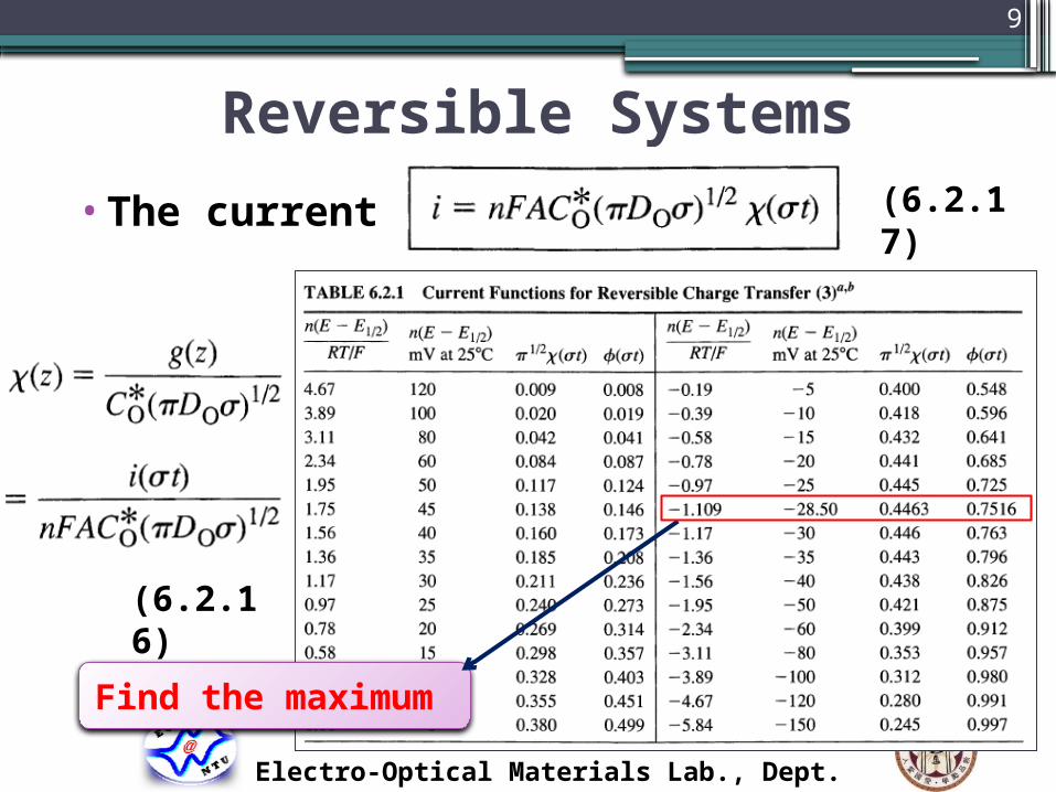
Reversible Systems
•The current
Electro-Optical Materials Lab., Dept. Chem. Eng., NTU
Find the maximum
(6.2.17)
(6.2.16)

10
Reversible Systems
•Peak current (at 25 )℃
•Peak potential
•Half-peak potential
Electro-Optical Materials Lab., Dept. Chem. Eng., NTU
ipA
A cm2
Co* mol/cm3
Docm2/sec
ν V/sec
(6.2.19)
(6.2.20)
(6.2.21)

11
Reversible Systems
Electro-Optical Materials Lab., Dept. Chem. Eng., NTU
(6.2.22)
ip ∝ ν1/2
i ∝ ν1/2
Ep ≠Ep(ν)
For reversible rxn

12
Detection limit of LSV• [Definition] The ratio of charging to Faradaic current
•<Assumption> Absence of adsorption/desorption influence either double
layer or Faradaic process
Electro-Optical Materials Lab., Dept. Chem. Eng., NTU
Faradaic current
Chargingcurrent

13
Detection limit of LSV•Capacitance of double layer
Electro-Optical Materials Lab., Dept. Chem. Eng., NTU
For DME
noise
signal

14
Detection limit of LSV•Effect of double layer charging at different sweep
rate
Electro-Optical Materials Lab., Dept. Chem. Eng., NTU
ν ↑ → ic /ip ↑Co* ↓ → ic /ip ↑The noise grows!

15
6.3 Totally Irreversible Systems
• Irreversible reaction•Boundary condition
•The current
Electro-Optical Materials Lab., Dept. Chem. Eng., NTU
(6.3.1)
(6.3.6)

16
Totally Irreversible Systems
•Peak current
•Peak potential
Electro-Optical Materials Lab., Dept. Chem. Eng., NTU
ip ∝ ν1/2
i ∝ ν1/2
Ep =Ep(ν)
For totally irrev.
(6.3.8)
(6.3.10)
(6.3.11)

17
6.4 Quasi-reversible Systems
•Boundary condition
•Parameter Λ
Electro-Optical Materials Lab., Dept. Chem. Eng., NTU
Do=DR=D
Λ ↑ , easy to reach equilibrium ( k0 ↑)
(6.4.4&5)
(6.4.2)

18
Quasi-reversible Systems
•Peak current
•Peak potential
Electro-Optical Materials Lab., Dept. Chem. Eng., NTU
For quasi-rev
ip ∝ ν1/2 (6.4.7)
(6.4.7)(6.4.8)

19
Summary
•Zone boundary for LSV
Electro-Optical Materials Lab., Dept. Chem. Eng., NTU
Reversible (Nernstian)Λ ≥ 15
k0 ≥0.3 ν1/2 cm/s
Quasi-reversible15 ≥ Λ ≥ 10-2(1+ )𝝰
0.3 ν1/2≥ k0 ≥2x10⁻⁵ν1/2 cm/s
Irreversible10-2(1+ ) 𝝰 ≥ Λ
k0 ≤ 2x10⁻⁵ν1/2 cm/s
Λ = Λ(ν)
20
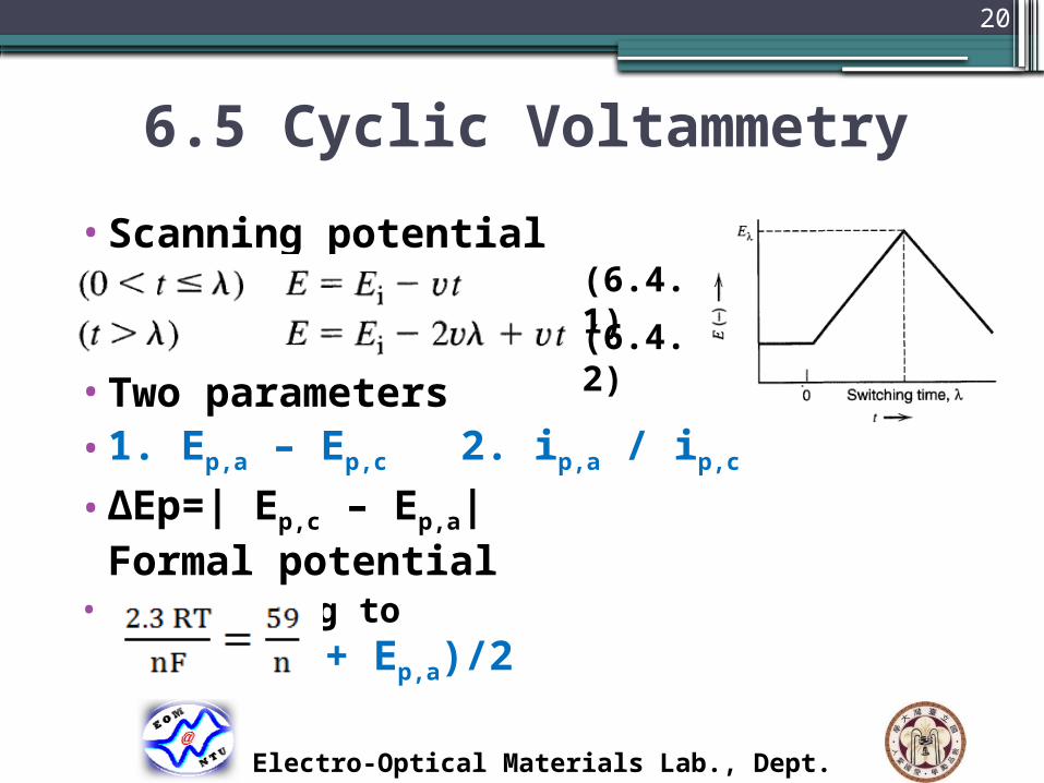
6.5 Cyclic Voltammetry
•Scanning potential
•Two parameters•1. Ep,a – Ep,c 2. ip,a / ip,c
•ΔEp=| Ep,c – Ep,a| Formal potential
• approaching to E0’= (Ep,c + Ep,a)/2
Electro-Optical Materials Lab., Dept. Chem. Eng., NTU
(6.4.1)(6.4.2)
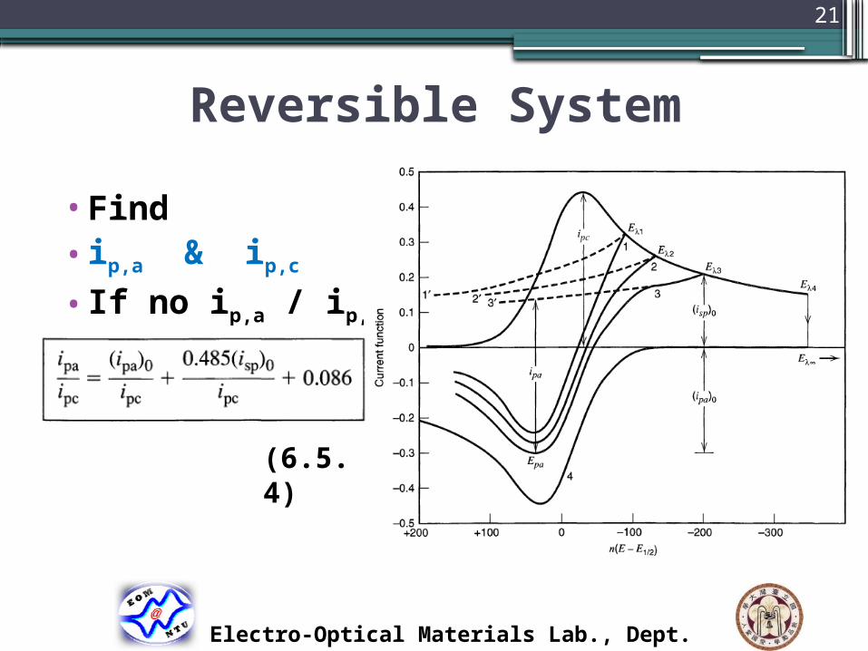
21
Reversible System
•Find• ip,a & ip,c
• If no ip,a / ip,c
Electro-Optical Materials Lab., Dept. Chem. Eng., NTU
(6.5.4)

22
Quasi-reversible System
•Wave shape & ΔEp f(∝ ν, α,k0,Eλ)
•Equivalent parameter
•For 0.3 <α< 0.7 the ΔEp is nearly
independent of α
•Ψ↑ as k0 ↑ or ν ↓ then ΔEp ↓
Electro-Optical Materials Lab., Dept. Chem. Eng., NTU
(6.5.5)
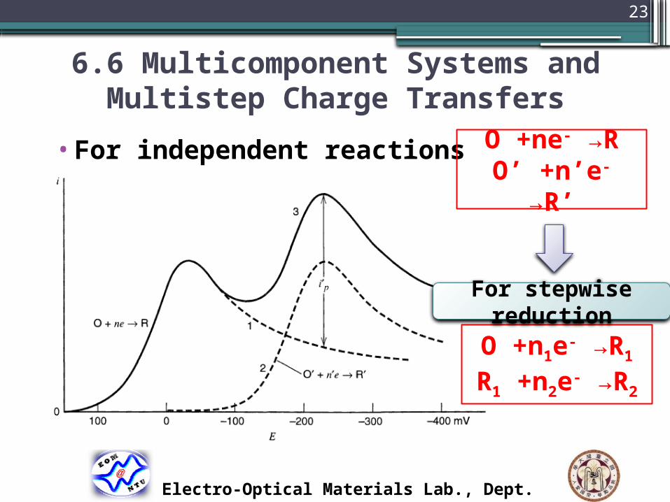
23
6.6 Multicomponent Systems and Multistep Charge Transfers
•For independent reactions
Electro-Optical Materials Lab., Dept. Chem. Eng., NTU
O +ne- →RO’ +n’e- →R’
O +n1e- →R1
R1 +n2e- →R2
For stepwise reduction

24
Peak Search
Electro-Optical Materials Lab., Dept. Chem. Eng., NTU
Method for obtaining baseline for measurement of ip’ of second wave
Method of allowing current of first wave to decay before scanning second wave

25
Electrode reaction coupled with chemical reaction (Chapter 12)
1. O +ne- R 5. ⇌2. O +ne- →R3. 6. 4. 7. 8.
O +ne- R⇌R Z⇌
O +ne- R⇌R → Z
O +ne- R⇌R +Z →O
O +ne- → RR +Z →O
Z O ⇌O +ne- R⇌
Z O ⇌O +ne- → R
Er
Ei
CrEr
CrEi
ErCr
ErCi
ErCi’
EiCi’
Electro-Optical Materials Lab., Dept. Chem. Eng., NTUCatalytic

26
CV Application –Diffusion control or Kinetic control
•Diffusion control
•Surface reaction control
Electro-Optical Materials Lab., Dept. Chem. Eng., NTU
(6.2.19)
(14.3.12)
For diffusion control ip ∝ ν1/2
For surface reaction controlip ∝ ν

27
CV Application – Surface reaction control
•PEDOT/FAD Electrode (達人‘ s work)
Electro-Optical Materials Lab., Dept. Chem. Eng., NTU
0 40 80 120 160 200-300
-200
-100
0
100
200
300
Ipa
Y=1.15X, R2= 0.998 Ipc
Y=-1.34X, R2= -0.998
Curr
ent den
sity
(A
cm
-2)
Scan rate (mV s-1)-0.6 -0.5 -0.4 -0.3 -0.2 -0.1 0.0 0.1 0.2
-0.5
-0.4
-0.3
-0.2
-0.1
0.0
0.1
0.2
0.3
0.4
3.125 to 200 mV s-1
3.125 to 200 mV s-1
Cur
rent
den
sity
(m
Acm
-2)
E (V vs. Ag/AgCl/sat'd KCl)
Modified electrode – surface reaction control

28
CV Application – Diffusion control
Electro-Optical Materials Lab., Dept. Chem. Eng., NTU
Diffusion control
29
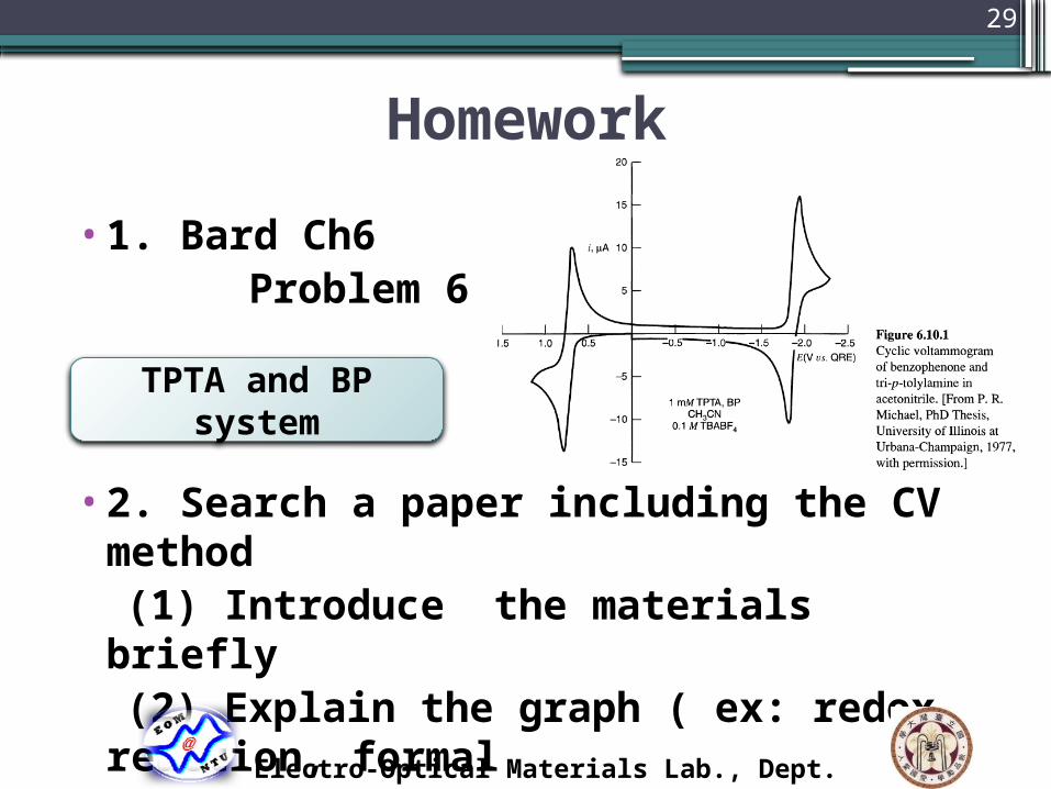
Homework
•1. Bard Ch6 Problem 6.6
•2. Search a paper including the CV method (1) Introduce the materials briefly (2) Explain the graph ( ex: redox reaction, formal potential, reversible/irreversible……)
TPTA and BP system
Electro-Optical Materials Lab., Dept. Chem. Eng., NTU

30
Reference1. J. Bard and L. R. Faulkner, Electrochemical methods: fundamentals
and applications, 2nd ed., John Wiley & Sons, Inc., New York (2001).
2. Applied Electrochemistry Notes (嘉筠、仲偉)
3. Handout of Ch 6 (瑋翰)
4. Joseph Wang, Analytical
Electrochemistry, 3rd ed., John Wiley
& Sons, Inc., (2006)
5. 達人學長’ s work
6. M. Y. Yen et al., RSC Adv., 2012, 2, 2725-2728.
Electro-Optical Materials Lab., Dept. Chem. Eng., NTU
Thanks for your attention!