Embed Size (px)
Citation preview
Electrochemical Impedance of Ion-Exchange Membranes in TernarySolutions with Two CounterionsA. A. Moya*
Departamento de Física, Universidad de Jaen, Edificio A-3, Campus Universitario de Las Lagunillas - 23071 Jaen, Spain
ABSTRACT: This paper aims to study the electrochemical impedance of a systemconsisting of an ion-exchange membrane and two diffusion boundary layers on bothsides of the membrane bathed in ternary electrolyte solutions with two counterions.An approximate analytical expression has been arranged for the impedance of anideal ion-exchange membrane system for counterions with identical charge numberon the basis of the Nernst−Planck−Donnan equations under electroneutrality. Theelectrochemical impedance for different values of the direct electric current of ion-exchange membrane systems with univalent ions has been numerically obtainedfrom the Nernst−Planck and Poisson equations. The results have been comparedwith the approximate analytical expressions in different arrangements of practicalinterest, including conventional electrodialysis, bi-ionic conditions, and reverseelectrodialysis. Our results provide new insights into the role played by thegeneralized expressions of the transport numbers, electrolyte diffusion coefficients,limiting electric currents, and membrane resistance in the interpretation of electrochemical impedances of ion-exchangemembranes in ternary electrolyte solutions with two counterions. Moreover, new physical insights emerge from the analysis ofthe conductive contribution to the total impedance of the system.
1. INTRODUCTIONCharacterization of electrodiffusive ionic transport processes bymeans of electrochemical impedance spectroscopy techniques iscurrently a classical issue in physical chemistry. The availablenumerical simulation programs, precise instrumentation, andinteresting technological applications have provided new insightsin the field of impedance spectroscopy of ion-exchangemembrane systems. Such membranes find a wide range ofapplication in the fields of ion-selective electrodes used aschemical sensors and brackish water or seawater desalination.1
Recently, there is also an increasing interest in applications forrenewable energy sources such as reverse electrodialysis.2
Moreover, the ion-exchange membranes are used as separatorsin low-temperature fuel cells and rechargeable batteries,especially in redox flux batteries.3 An ion-exchange membranesystem is constituted by a layer of material with inner electriccharge that separates two solution phases. Conventionalmembranes present fixed or mobile ionic sites, and they arepartially permeable or fully impermeable to at least one dissolvedionic component. An ion-exchange membrane is ideal when thefluxes of the co-ions through it are zero.Since the work of Sistat et al.,4 a number of papers dealing with
the electrochemical impedance of systems constituted by an ion-exchange membrane and two diffusion boundary layers (DBLs)adjacent to the membrane have appeared in the literature. Theseworks include studies on the effect of the displacement electriccurrent,5 the diffusion coefficients dependent on the ionicconcentrations,6 and the highest values of the direct componentof the electric current7,8 on the impedance of ideal ion-exchangemembrane systems by using the Nernst−Planck−Donnanequations under electroneutrality. Moreover, the influence of
the capacitance of the diffuse double layers,9 degree ofinhomogeneity of the membrane fixed-charge,10,11 directcomponent of the electric current,12 degree of asymmetry ofthe bathing concentrations,13 smallest values of the fixed-chargeconcentration,14 and rectangular structure of fluidic nano-channels15 on the impedance of nonideal ion-exchangemembranes have been studied in depth on the basis of theNernst−Planck and Poisson equations. However, these previousstudies deal with only the ionic transport processes of a singlebinary electrolyte.Multi-ionic transport through ion-exchange membranes is also
of interest, particularly in studies on bi-ionic electric potential ofmembranes,16−18 water dissociation in anion-exchange mem-branes,19,20 or ionic transport through bipolar membranes.21,22
Recently, the dynamic of the electric potential in both multi-ionicliquid junctions23,24 and infinitesimal membranes25 and theimpact of adding salts on the steady-state and transient electricalproperties of electrolytic cells26 and Li-ion rechargeablebatteries27 have also been analyzed. Moreover, a detailed studyon the electrochemical impedance of ion-selective electrodesunder membrane control, i.e., by ignoring the DBLs adjacent tothe membrane, has been presented for multi-ion systems.28,29
Although the study of the steady-state multi-ionic electricpotential in ion-exchange membrane systems under equilibriumconditions is a classical issue in the literature,30−35 to ourknowledge, theoretical studies on the electrochemical impedanceof such systems with at least three dissolved ions have not yet
Received: November 3, 2013Revised: January 12, 2014
Article
pubs.acs.org/JPCC
© XXXX American Chemical Society A dx.doi.org/10.1021/jp4108238 | J. Phys. Chem. C XXXX, XXX, XXX−XXX
been reported. Multi-ionic transport process through ion-exchange membranes is conditioned by the ionic partitioning,36
but it seems desirable to know the conditions in which theimpedance plots can be interpreted by using single electricelements in a way similar to that in binary electrolyte solutions. Itis the main purpose of this paper to contribute to this area byperforming a novel theoretical study of the characteristics of theelectrochemical impedance of ion-exchange membranes im-mersed in ternary electrolyte solutions with two counterions.The particular system under study is constituted by a
membrane with negative fixed charge and two DBLs on bothsides of the membrane, being considered the ionic transport of amixture of two binary electrolytes with common anion. Anapproximate analytical expression is arranged for the electro-chemical impedance of an ideal ion-exchange membrane systemwhere the counterions present identical charge number on thebasis of the Nernst−Planck flux equations, Donnan equilibriumrelations at the interfaces, electroneutrality condition, and thehypothesis of constant relative ionic composition of all thespecies into the DBLs. The electrochemical impedance of an ion-exchange membrane system is also numerically obtained fromthe Nernst−Planck and Poisson equations including the diffusedouble layers at the interfaces by using the network simulationmethod,37−39 which is mainly based on a finite differencescheme; it is of a nature similar to those successfully used inmixed conductors40−42 and batteries.43,44 The numerical resultsobtained for the impedance are then compared with theapproximate analytical expressions. The steady-state voltage−current characteristics and the electrochemical impedance fordifferent values of the direct electric current of ion-exchangemembrane systems are investigated in different situations ofpractical interest with univalent ions. First, we consider amembrane placed between two solutions with the same chemicalcomposition because these systems find application in the field ofconventional electrodialysis. Second, we choose an ion-exchangemembrane under bi-ionic conditions because of its interest in thefield of electrochemical sensors. Finally, a membrane placedbetween two solutions with different salt concentrations isconsidered because this is the appropriate arrangement to obtaina salinity gradient in the field of energy production throughreverse electrodialysis.The obtained numerical results are in good agreement with the
approximate analytical solutions, and they show that it is possibleto employ the single electric elements used in ion-exchangemembranes with binary electrolytes to interpret the electro-chemical impedance plots obtained with membranes in ternarysolutions, which consist of a high-frequency arc associated withthe migration processes and the electric displacement currentand a low-frequency arc associated with the electrolyte diffusionprocess. Our results provide new insights in relation to the use ofthe generalized expressions of the transport numbers, electrolytediffusion coefficients, limiting electric currents, and resistance ofthe membrane in the interpretation of electrochemicalimpedances of ion-exchange membranes in ternary electrolytesolutions with two counterions. Moreover, new physical insightsemerge from the analysis of the conductive contribution to thetotal impedance of the system, which appears to be significant atvalues of the dc current close to the limiting current.
2. THEORETICAL BASIS2.1. Ionic Transport in Ion-Exchange Membrane
Systems. Let us consider an ion-exchange membrane thatextends from x = 0 to x = d and two DBLs adjacent to the
membrane lying from x= −δL to x = 0 and from x = d to x = d +δR. Themembrane is bathed by two bulk solutions constituted bya mixture of two binary electrolytes with a common anion, and itwill be assumed to have a negative fixed-charge. Ionic transportprocess is supposed to be one-dimensional and perpendicular tothe membrane|solution interface, with x the direction oftransport. In accord with previous works on ionic transportthrough ion-exchange membranes,45−49 the dimensionlessequations (see Appendix A) determining the behavior of thesystem at time t are the laws of mass conservation or continuityequations
∂∂
= −∂
∂=
J x t
xc x t
ti
( , ) ( , ), 1, 2, 3i i
(1)
the Nernst−Planck flux equations written for dilute solutions
ϕ= −∂
∂+ ∂
∂⎡⎣⎢
⎤⎦⎥J x t D
c x tx
z c x tx tx
( , )( , )
( , )( , )
i ipi
i i(2)
and the Poisson equation
∑ θ∂∂
= −=
⎡⎣⎢⎢
⎤⎦⎥⎥
x tx
z c x t xD( , )
( , ) ( )i
i i1
3
(3)
where
ε ε ϕ= = − ∂∂
x t E x tx tx
D( , ) ( , )( , )
(4)
Here Ji(x,t), Dip, ci(x,t), and zi denote the ionic flux, the diffusioncoefficient, the molar concentration, and the charge number ofion i, respectively. We consider the ions i = 1 and i = 2 to be thecations and i = 3 to be the anion. In this work, the ion diffusioncoefficients are different in the DBLs and in the ion-exchangemembrane, andDiS andDiM stand for the diffusion coefficients ofion i in the solution (S) and membrane (M) phases, respectively.The electric potential is represented by ϕ(x,t), electricpermittivity by ε, electric displacement by D(x,t), and electricfield by E(x,t). The constants F, R, and T have their usualmeanings: Faraday constant, ideal gas constant, and absolutetemperature, respectively. θ(x) is the fixed-charge concentration,which is presumed known and expressed in a general way as afunction of position, x. In this case, it is given by
θ
δ
δ
=
− ≤ <
− ≤ ≤< ≤ +
⎧⎨⎪
⎩⎪x
x
X x d
d x d
( )
0, 0
, 0
0,
L
R (5)
where the membrane fixed-charge concentration, X, is assumedto be homogeneously distributed inside the membrane.On the other hand, the faradaic electric current, If, is
∑==
I x t z J x t( , ) ( , )i
i if1
3
(6a)
and the displacement electric current, Id, is given by
ε= ∂∂
= ∂∂
I x tx tt
E x tt
D( , )
( , ) ( , )d (6b)
Now, the total electric current, I, is the sum of the faradaic anddisplacement currents
= +I x t I x t I x t( , ) ( , ) ( , )f d (7a)
The Journal of Physical Chemistry C Article
dx.doi.org/10.1021/jp4108238 | J. Phys. Chem. C XXXX, XXX, XXX−XXXB
However, from the above equations one obtains
∂∂
=I x tx
( , )0
(7b)
i.e., I is not a function of x.50 Thus, the total electric current canbe evaluated at an arbitrary point such as x = −δL, and it can bewritten as
∑ δδ
= − +−
=
I t z J td t
dtD
( ) ( , )( , )
ii i
1
3
LL
(7c)
In order to study the response of the membrane system to anexternally applied electric current perturbation, the boundaryconditions can be expressed as
δ γ− = = −c t czz
c( , )1 L 1L 3
1L
L
(8a)
δ γ+ = = −c d t czz
c( , )1 R 1R 3
1R
R
(8b)
δ γ− = = − −c t czz
c( , ) (1 )2 L 2L 3
2L
L
(9a)
δ γ+ = = − −c d t czz
c( , ) (1 )2 R 2R 3
2R
R
(9b)
δ− = =c t c c( , )3 L 3L L
(10a)
δ+ = =c d t c c( , )3 R 3R R
(10b)
∑δδ
−= − −
=
d tdt
I t z J tD( , )
( ) ( , )i
i iL
1
3
L(11a)
ϕ δ+ =d t( , ) 0R (11b)
eqs 8−11 specify all the conditions to be imposed on the solutionof the Nernst−Planck and Poisson equations. In these equations,cL and cR are the total concentrations of the common co-ion intothe left and right solutions, while γL and γR are the ratios of thebathing concentration of the binary electrolyte containing thecounterion of charge z1 to the total anion concentration in theleft and right solutions, respectively. In this way, eqs 8−10indicate that the system is electrically neutral at the outerboundaries of the DBLs. In eq 11a, I(t) is the externally appliedelectric current, and it is used to calculate the value of the electricdisplacement at the outer boundary of the left DBL. Equation11b defines the reference level for the electric potential at theouter boundary of the right DBL.2.2. Electric Current Perturbation. It is well-known that
under small-signal ac conditions, the system variables may beseparated into steady-state and time-dependent parts by usingthe algebra of complex numbers. In particular, the co-ionconcentration and the electric potential can be written as
= + ωc x t c x c x( , ) ( ) ( )e j t3 DC 0 (12a)
ϕ ϕ ϕ= + ωx t x x( , ) ( ) ( )e j tDC 0 (12b)
where j = (−1)1/2 is the imaginary unit and ω is the circular orangular frequency, which can be written as a function of theconventional frequency, f
ω π= f2 (13)
To study the electrochemical impedance, the externallycontrolled electric current through the system is expressed as
= + ωI t I I( ) e j tDC 0 (14a)
and the electric potential at the outer boundary of the left DBL,ϕM(t) = ϕ(−δL,t), can be written as
ϕ ϕ ϕ= + ωt( ) e j tM MDC M0 (14b)
The electrochemical impedance, Z, is a complex quantity givenby the following equation:51
ωϕ
=Z jI
( ) M0
0 (15a)
and it can be expressed in the Euler or polar and rectangularforms as follows:
ω ω ω= | | = +ϕZ j Z Z jZ( ) e ( ) ( )jr i (15b)
where |Z|, φ, Zr, and Zi are modulus, phase, and real andimaginary parts of the impedance, respectively.
3. IDEAL ION-EXCHANGE MEMBRANE SYSTEMS3.1. General Governing Equations. Single analytical
expressions for a great number of variables can be easily obtainedin an ideal membrane system, i.e., a systemwith amembrane fullyimpermeable to the co-ions, by assuming the general followinghypothesis:52,53
• Electrical neutrality into the two DBLs and the membrane.• Constant relative ionic composition of all the species in the
DBLs.• Zero co-ion flux through the membrane.• Constant and linearly varying with position concen-
trations of the counterions inside the membrane, if theypresent identical valence.
• Electric potential obeying the Donnan equilibriumrelations at the two membrane−solution interfaces.
3.1.1. Diffusion Boundary Layers. We will denote by c theanionic (co-ion) concentration, and we will suppose that theionic concentrations in a DBL present the relative proportionthat is the same as that in the bathing solution:
γ γ= − = − − =czz
c czz
c c c(1 )K K13
12
3
23
(16)
If we define the transport number of ion i in the solution K (K = Lfor the left and K = R for the right solution), tiK, as the ratio of theconductivity of ion i to that of the solution
=∑ =
tz c D
z c Dii i i
i i i iK
2S
13 2
S (17a)
the following relation is obeyed:
+ + =t t t 11K 2K 3K (17b)
So, from eqs 2−4 and 6a, one obtains that the electric field in theDBL K, EK, is given by
γ γ=
− − −+E
D D Dz D
tdc
cdxt
z cDI
(1 )K
3S K 1S K 2S
3 3S3K
3K
32
3Sf
(18)
the co-ion flux obeys the continuity equation
The Journal of Physical Chemistry C Article
dx.doi.org/10.1021/jp4108238 | J. Phys. Chem. C XXXX, XXX, XXX−XXXC
∂∂
= − ∂∂
J
xct
3
(19a)
and it can be written as
= − +J Ddcdx
tz
I3 SK3K
3f
(19b)
where DSK is the electrolyte diffusion coefficient in the DBL K,and it is given by
= − + −D z zD t
zz z
D tz
( ) ( )SK 1 33S 1K
12 3
3S 2K
2 (20)
3.1.2. Membrane. Because the concentrations of thecounterions inside the membrane, c1 and c2, are related bymeans of the electrical neutrality condition
+ =z c z c X1 1 2 2 (21)
the ionic transport inside the membrane can be described by thefollowing equations:
∂∂
= −∂∂
J
xct
1 1(22a)
and
= −∂∂
+J Dcx
z D c E1 1M1
1 1M 1 m (22b)
where Em is now the electric field inside the membrane and it isrelated with the faradaic electric current through the system by
= − −∂∂
+ +
−
I z D Dcx
z D c z D X
z z D c E
( ) (
)
f 1 1M 2M1
12
1M 1 2 2M
1 2 2M 1 m (23)
Now we can calculate the ionic concentrations at the innerboundaries of the membrane, c (0)1 and c d( )1 , from the electricalneutrality condition
+ =
+ =
z c z c X
z c z c X1 1L 2 2L
1 1R 2 2R (24a)
and the Donnan equilibrium relations at the interfaces
=
=
zc
c zc
c
zc
c d zc
c d
1ln
(0)1
ln(0)
1ln
( )1
ln( )
1
1L
1 2
2L
2
1
1R
1 2
2R
2 (24b)
It is a well-known fact that the properties of the ionic transportprocesses through membranes strongly depend of the chargenumber of the ions because of the ionic partition at the interfaces.If both counterions present identical value of the charge number,z1 = z2, the ionic partitioning is
γ γ
γ γ
= = −
= = −
cXz
cXz
cXz
cXz
(1 )
(1 )
1L L1
2L L1
1R R1
2R R1 (24c)
whatever the remaining conditions may be. In this situation, theionic concentrations inside the membrane are not a function oftime. At this point, it must be noted that the partition coefficientshave not been incorporated into the theoretical description for
the sake of simplicity. In fact, it has been considered that thespecific ionic partition coefficients between the external and themembrane solutions are unity.36
3.2. Steady State. Because an ideal membrane system is thatin which the co-ion flux is zero, from eq 19b one obtains in thesteady state
=dcdx
tz D
I3K
3 SKDC
(25a)
The limiting electric current in a DBL is obtained when thesteady-state concentration gradient reaches its maximum value inthat DBL. From eq 25a with c(x = −δL) = cL and c(x = 0) = 0 orwith c(x = d) = 0 and c(x = d + δR) = cR, one obtains that thelimiting electric current in the DBL K is:
δ= −I
z D ctK3 SK
K
3K K (25b)
and eq 25a can be written as
δ= −dc
dxI cIDC
K
K K (25c)
If one denotes by βK the ratio of the dc electric current to itslimiting value
β =IIKDC
K (26)
from eq 25c, one finds that the anionic concentration in the leftDBL is
βδ
δ= −
+⎛⎝⎜
⎞⎠⎟c x c
x( ) 1DC
LL
L
L (27)
Then, by using eq 18, the electric potential difference in theneutral zone of the left DBL is
∫ϕ β= = −δ−
E xz
d1
ln(1 )DCL
0
L3
LL (28a)
while the Donnan equilibrium potential difference at the leftinterface is
ϕ = =z
cc z
cc
1ln
(0)1
ln(0)DC
dL
1
1L
1 2
2L
2 (28b)
Now, the anionic concentration in the right DBL is
βδ
δ= −
− −⎛⎝⎜
⎞⎠⎟c x c
x d( ) 1DC
RR
R
R (29)
the electric potential difference in the neutral zone of the rightDBL is
∫ϕ β= = − +δ+
E xz
d1
ln(1 )d
d
DCR
R3
R
R
(30a)
while the Donnan potential difference at the right interface isgiven by
ϕ = =z
c dc d z
c dc d
1ln
( )( )
1ln
( )( )DC
dR
1
1
1 2
2
2 (30b)
On the other hand, the electric potential difference throughthe membrane is
The Journal of Physical Chemistry C Article
dx.doi.org/10.1021/jp4108238 | J. Phys. Chem. C XXXX, XXX, XXX−XXXD
∫ϕ = E xdd
DCm
0m (31a)
and by supposing that the ionic concentrations vary linearly withposition inside the membrane
= +−
c x cc c
dx( )i i
i iL
R L(31b)
and by using eq 23, one finds
ϕ =+ ∑ −
∑ −
∑
∑=
=
=
=
I d z D c c
z D c c
z D c
z D c
( )
( )lni i i i i
i i i i i
i i i i
i i i iDCm DC 1
2M R L
12 2
M R L
12 2
M R
12 2
M L
(31c)
which coincides with the known expression for the equilibriummembrane potential34 when IDC = 0 and it constitutes anextended expression of the membrane potential to include thepolarization concentration. In this way, the steady-state electricpotential of the membrane system must be obtained as the sumof the several terms associated with the left DBL, the membrane,and the right DBL
ϕ ϕ ϕ ϕ ϕ ϕ= + + + +MDC DCL
DCdL
DCm
DCR
DCdR
(32a)
and it can be expressed as
ϕββ
ϕ ϕ ϕ= −+−
+ Δ + Δ +⎛⎝⎜
⎞⎠⎟z z
1 1ln
1
1MDC1 3
R
L1 2 DC
m
(32b)
where
ϕγγ
γγ
Δ = =−−z
c
c z
c
c1
ln1
ln(1 )
(1 )11
RR
LL
2
RR
LL
(32c)
and
ϕΔ = =z
cc z
cc
1ln
1ln2
1
1L
1R 2
2L
2R (32d)
It must be noted that it is preferable to use these two above terms,Δϕ1 and Δϕ2, in the theoretical description in order to includethose situations in which γL or γR take the values 0 or 1, such asoccurs for example with bi-ionic membranes.One of the more important steady-state values describing the
impedance of a system is the dc resistance, which is defined as thederivative of the electric potential with respect the electriccurrent. In the general case, this resistance is difficult to obtainbecause the ionic concentrations inside the membrane dependon the electric current due to the ionic partitioning. Now, if oneconsiders counterions presenting identical charge number, z1 =z2, the ionic concentrations inside the membrane are given by theionic partitioning of eq 24c, they are not a function of the dcelectric current, and the dc resistance of the system, RDC, can beexpressed as
ϕβ
β
= = −−
++
+
⎛⎝⎜
⎞⎠⎟⎛⎝⎜⎜
⎞⎠⎟⎟
RI z z I
I
d
d1 1 1
(1 )
1(1 )
R
DCMDC
DC 1 3 L L
R RM
(33a)
where the membrane resistance, RM, is given by
=∑ −
∑
∑=
=
=
Rd
z D c c
z D c
z D c( )ln
i i i i i
i i i i
i i i iM
12 2
M R L
12 2
M R
12 2
M L (33b)
Moreover, if we consider a membrane placed between twosolutions with identical chemical composition (γL = γR), thepotential difference through the membrane can be obtained fromeq 31c, and it is expressed as
ϕ ϕ= − Δ + R IDCm
2 M DC (34a)
where the resistance of the membrane is
=∑ =
Rd
z D ci i i iM
12 2
M L (34b)
In this way, the steady-state potential of the membrane systemcan be expressed as
ϕββ
= −+−
+ +⎛⎝⎜
⎞⎠⎟z z z
cc
R I1 1
ln1
11
lnMDC1 3
R
L 1
R
L M DC
(34c)
and the dc resistance of the membrane system is given by eq 33a.3.3. Alternating Current. 3.3.1. Low Frequency. In the low-
frequency range, the displacement electric current can beconsidered zero. Then, because the continuity equation for theanion in the DBL K is
∂∂
= −∂∂
= ∂∂
ct
J
xD
cx
3SK
2
2 (35a)
by considering eq 12a, one obtains
ω =j c Dc
xdd0 SK
202 (35b)
and by using the following boundary conditions
δ= − =c x( ) 00 L (36a)
δ= −
=
⎛⎝⎜
⎞⎠⎟
cx
I cI
dd x
0
0
0L
L L (36b)
the general solution of eq 35b in the left DBL is
α
α
α= −
δδ+( )
c xI cI
( )sinh
cosh
x
00
L
L L
L
L
L
L
(36c)
where
α δω
ω= = Λj
DjL L
SLL
(36d)
From eq 28a after several arrangements, is obtained that the accomponent of the electric field in the left DBL, EL0, is:
γ γ=
− − −
+ −⎛⎝⎜
⎞⎠⎟
ED D D
z Dt
xc
ct I
z D ct Iz D
cc
(1 )
dd
L03S L 1S L 2S
3 3S3L
0
DC
3L 0
32
3S DC
3L DC
32
3S
0
DC2
(37a)
the electric potential difference in the neutral zone of the leftDBL is
∫ϕ =δ−
E xd0L
0
L0L (37b)
The Journal of Physical Chemistry C Article
dx.doi.org/10.1021/jp4108238 | J. Phys. Chem. C XXXX, XXX, XXX−XXXE
while the Donnan potential difference at the left interface can beevaluated only for counterions with identical value of the chargenumber, z1 = z2, because in other cases the ionic concentrationsinside the membrane are a function of time, and it is given by
ϕβ
αα
= −==
=−z
c xc x z
II
1 ( 0)( 0)
1(1 )
tanh0dL
1
0
DC 1
0
L L
L
L
(37c)
From the integration of eq 37b, one obtains that the impedanceof the left DBL is
ϕ ϕ=
+= + +Z
IZ Z ZL
0L
0dL
0dL mL cL
(38a)
where the diffusion impedance, ZdL, which comes not only fromthe diffusion in the DBL but also from the Donnan equilibriumrelation, is
γ γβ
αα
= −− − −
−
⎛⎝⎜
⎞⎠⎟Z
zD D D
z Dt
I1 (1 ) 1
(1 )tanh
dL1
3S 1S 2S
3 3S3L
L L
L
L
(38b)
the ohmic impedance, ZmL, is
δ ββ
= −−
Zt
z D c
ln(1 )mL
L 3L
32
3SL
L
L (38c)
and the impedance of conduction, ZcL, is
∫δ βα α
α ξβ ξ
ξ=−
Zt
z D c1
coshsinh( )
(1 )dcL
3L L L
32
3SL
L L 0
1L
L2
(38d)
where ξ = (x + δL)/δL is an integration variable. In this way, aspointed out by Sistat et al.,4 the impedance of a DBL presentsthree contributions: ZdL is due to the variation in electricpotential by a change in concentration profile; ZmL is due to thevariation in electric potential by a change in electric current whenassuming the concentration profile does not change; and ZcL isdue to the variation in electric potential by a change inconcentration profile produced by an electric current. It is worthnoting that the conductive impedance does not have an analyticalsolution and must be numerically obtained,4 but its limits at thelowest and highest frequencies are
δ ββ β
=−
+−ω→
⎡⎣⎢⎢
⎤⎦⎥⎥Z
tz D c
limln(1 ) 1
10cL
L 3L
32
3SL
L
L L (39a)
=ω→∞
Zlim 0cL (39b)
If we calculate the limits of the impedance of the left DBL, ZL, atthe lowest and the highest frequencies, we find that the geometricresistance of the left DBL, RacL, is given by:
δ ββ
= = −−
ω→∞R Z
tz D c
limln(1 )
acL LL 3L
32
3SL
L
L (40a)
and the dc resistance of the left DBL, RDCL, is
β= = −
−ω→
⎛⎝⎜
⎞⎠⎟R Z
z z Ilim
1 1 1(1 )DCL
0L
1 3 L L (40b)
In this way, by assuming that the frequency dependence of theconduction impedance is similar to that of the diffusionimpedance,4,7,8 the impedance of the left DBL can be written as
αα
= + −Z R R R( )tanh
L acL DCL acLL
L (40c)
Now, by using the following boundary conditions
δ= + =c x d( ) 00 R (41a)
δ= −
=
⎛⎝⎜
⎞⎠⎟
cx
I cI
dd x d
0 0R
R R (41b)
the general solution of eq 33b in the right DBL is
α
α
α= −
δδ
− −( )c x
I cI
( )sinh
cosh
x d
00
R
R R
R
R
R
R
(41c)
where
α δω
ω= = Λj
DjR R
SRR
(41d)
Now, the ac component of the electric field in the right DBL, ER0,is
γ γ=
− − −
+ −⎛⎝⎜
⎞⎠⎟
ED D D
z Dt
xc
ct I
z D ct Iz D
cc
(1 )
dd
R03S R 1S R 2S
3 3S3R
0
DC
3R 0
32
3S DC
3R DC
32
3S
0
DC2
(42a)
the electric potential difference in the neutral zone of the rightDBL is
∫ϕ =δ+
E xdd
d
0R
R0R
(42b)
while the Donnan potential difference for counterions withidentical valence at the right interface is
ϕβ
αα
= −==
=+z
c x dc x d z
II
1 ( )( )
1(1 )
tanh0dR
1
0
DC 1
0
R R
R
R
(42c)
From the integration of eq 41b, one obtains that the impedanceof the right DBL is
ϕ ϕ=
+= + +Z
IZ Z ZR
0R
0dR
0dR mR cR
(43a)
where the diffusion impedance, ZdR, is
γ γβ
αα
= −− − −
+
⎛⎝⎜
⎞⎠⎟Z
zD D D
z Dt
I1 (1 ) 1
(1 )tanh
dR1
3S R 1S R 2S
3 3S3R
R R
R
R
(43b)
the ohmic impedance, ZmR, is
δ ββ
=+
Zt
z D c
ln(1 )mR
R 3R
32
3SR
R
R (43c)
and the impedance of conduction, ZcR, is
∫δ βα α
α ξβ ξ
ξ=−−
Zt
z D c1
coshsinh( )
(1 )dcR
3R R R
32
3SR
R R 1
0R
R2
(43d)
where ξ = (x − d − δR)/δR is the integration variable. Now, thelimits of the conduction impedance of the right DBL at thelowest and highest frequencies are
The Journal of Physical Chemistry C Article
dx.doi.org/10.1021/jp4108238 | J. Phys. Chem. C XXXX, XXX, XXX−XXXF
δ ββ β
= −+
−+ω→
⎡⎣⎢⎢
⎤⎦⎥⎥Z
tz D c
limln(1 ) 1
10cR
R 3R
32
3SR
R
R R (44a)
=ω→∞
Zlim 0cR (44b)
From the evaluation of the limits of the impedance of the rightDBL at the lowest and highest frequencies, we find that thegeometric resistance of the right DBL, RacR, is given by
δ ββ
= =+
ω→∞R Z
tz D c
limln(1 )
acR RR 3R
32
3SR
R
R (45a)
and the dc resistance of the right DBL, RDCR, is
β= = −
+ω→
⎛⎝⎜
⎞⎠⎟R Z
z z Ilim
1 1 1(1 )DCR
0R
1 3 R R (45b)
In this way, by assuming that the frequency dependence of theconductive impedance is similar to that of the diffusionimpedance, the impedance of the right DBL can be written as
αα
= + −Z R R R( )tanh
R acR DCR acRR
R (45c)
Finally, the electric potential difference through themembraneis
∫ϕ = =E x R Idd
0m
0m0 M 0 (46)
Now, because we ignore the displacement current in the low-frequency range, the impedance ZW can be obtained from thefollowing equation:
ϕ ϕ ϕ=
+ += + +Z
IZ R ZW
0L
0m
0R
0L M R
(47a)
In this way, the low-frequency diffusion impedance of the totalion-exchange membrane system, ZW, can be written as:
αα
αα
= + − + −Z R R Rtanh
R Rtanh
( ) ( )W ac DCL acLL
LDCR acR
R
R
(47b)
where
= + +R R R Rac M acL acR (47c)
and the dc resistance of the system at the limit of the lowestfrequencies is
β β= = −
−+
+
+ = + +
ω→
⎛⎝⎜
⎞⎠⎟⎛⎝⎜⎜
⎞⎠⎟⎟R Z
z z I I
R R R R
lim1 1 1
(1 )1
(1 )
R
DC0
W1 3 L L R R
M DCL DC M (47d)
which agrees with eq 33a obtained from the steady-state analysis.It must be taken into account that the low-frequency
impedance is the superposition of the Warburg impedancescorresponding to the left and right DBLs, and the characteristicsfrequencies are
π=
Λf
2.542dL
L (48a)
and
π=
Λf
2.542dR
R (48b)
It is worth noting that the low-frequency impedance of an ion-exchange membrane system can be considered as that of a singleelectric circuit constituted by the series association of fiveelements: the ohmic resistances of the left and right DBLs, themembrane resistance, and the two Warburg elements corre-sponding to the left and right DBLs.
3.3.2. High Frequency. In the high-frequency range, one canassume c0 = 0 along the system. Then, by taking into account eqs4 and 7a, one obtains by integration of eq 18 the followingexpressions:
ϕωε
ϕδ
ϕωε
ϕ ϕωε
ϕδ
= + = + = +IR
jR
jd R
j00L
acL
0L
L
0m
M
0m
0R
acR
0R
R(49a)
Because the high-frequency or geometric impedance is given by
ϕ ϕ ϕ=
+ +Z
Ig0L
0m
0R
0 (49b)
one finds the following expression:
ω ω ω=
++
++
+Z
Rj R C
Rj R C
Rj R C1 1 1g
acL
acL gL
M
M gM
acR
acR gR
(49c)
where the geometric capacitances areεδ
=CgLL (50a)
ε=CdgM (50b)
εδ
=CgRR (50c)
In this way, this geometric impedance is the superposition of thethree simple geometric impedances of the left DBL, membrane,and right DBL, the characteristic frequencies being
π=f
R C1
2gLacL gL (51a)
π=f
R C1
2gMacM gM (51b)
π=f
R C1
2gRacR gR (51c)
It must be noted that the high-frequency impedancecorresponds to that of an electric circuit constituted by theseries association of three single RC parallel branches. Moreover,it must be also noted that the capacitance of the diffuse doublelayer, such as included into the classical Randles circuit describingthe impedance of the mass- and charge-transfer processes in anelectrochemical interface,5 has been neglected in our study. Inthe case of a ternary electrolyte, the diffuse double-layercapacitance at the left, CdlL, and the right interfaces, CdlR, aregiven by
ε= + +C z c z c z c( )dlL 12
1L
22
2L
32
3L
(52a)
ε= + +C z c z c z c( )dlR 12
1R
22
2R
32
3R
(52b)
In the Randles circuit, each one of them appears connected inparallel with the Warburg impedance of the corresponding DBL.
The Journal of Physical Chemistry C Article
dx.doi.org/10.1021/jp4108238 | J. Phys. Chem. C XXXX, XXX, XXX−XXXG
However, we have checked that they exert a very poor influencebecause there is no charge-transfer resistance in the interfacesand the length of the systems will be considered to be muchgreater than the Debye length.54
4. RESULTS AND DISCUSSIONIn this paper, the numerical results are obtained by using thenetwork simulation method, which is briefly described inAppendix B, and they are presented for ion-exchange membranesplaced between two solutions varying the chemical composition,γL and γR, the co-ion concentration, cL and cR, and the directcomponent of the electric current, IDC. In the considered system,the counterions present identical values for the charge number, z1= z2 = 1, and the following other parameters: z3 =−1, X = 10, d =1000, δL = δR = 1000, ε = 1, D1S = 1000, D2S = 1500, D3S = 1500,D1M = 100, D2M = 150, and D3M = 150. This system couldcorrespond to a membrane immersed in a mixture of NaCl andKCl. The ionic diffusion coefficients in the membrane have beenchosen as a tenth of those in the solutions for the sake ofsimplicity. In particular, this choice involves that the ratio of thediffusion coefficients of the ions in the membrane takes a valuethat is the same as that in the solutions.4.1. Effect of Changing the Chemical Composition in
an Unbiased Symmetric System. First, we will study theelectrochemical impedance of the ion-exchange membranesystem above-described when the membrane is placed betweentwo symmetric solutions with identical chemical composition, γL= γR = γ, and salt concentrations cL = cR = 0.1 for IDC = 0 anddifferent values of γ. This arrangement is typical in experimentalstudies on the electrochemical properties of ion-exchangemembranes used in electromembrane processes based onconventional electrodialysis with multi-ionic electrolytes.55−58
Figure 1 gives the complex-plane impedance plots for three
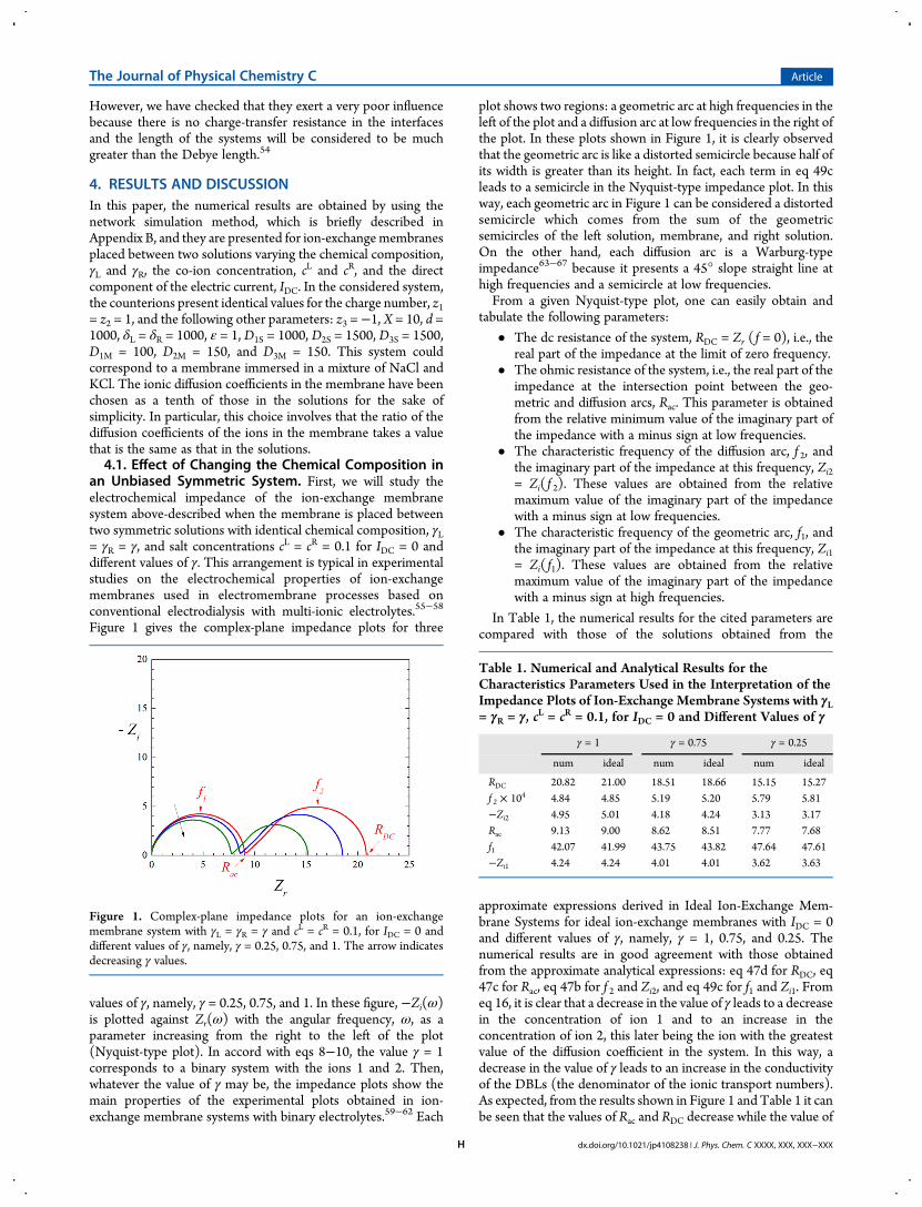
values of γ, namely, γ = 0.25, 0.75, and 1. In these figure, −Zi(ω)is plotted against Zr(ω) with the angular frequency, ω, as aparameter increasing from the right to the left of the plot(Nyquist-type plot). In accord with eqs 8−10, the value γ = 1corresponds to a binary system with the ions 1 and 2. Then,whatever the value of γ may be, the impedance plots show themain properties of the experimental plots obtained in ion-exchange membrane systems with binary electrolytes.59−62 Each
plot shows two regions: a geometric arc at high frequencies in theleft of the plot and a diffusion arc at low frequencies in the right ofthe plot. In these plots shown in Figure 1, it is clearly observedthat the geometric arc is like a distorted semicircle because half ofits width is greater than its height. In fact, each term in eq 49cleads to a semicircle in the Nyquist-type impedance plot. In thisway, each geometric arc in Figure 1 can be considered a distortedsemicircle which comes from the sum of the geometricsemicircles of the left solution, membrane, and right solution.On the other hand, each diffusion arc is a Warburg-typeimpedance63−67 because it presents a 45° slope straight line athigh frequencies and a semicircle at low frequencies.From a given Nyquist-type plot, one can easily obtain and
tabulate the following parameters:
• The dc resistance of the system, RDC = Zr ( f = 0), i.e., thereal part of the impedance at the limit of zero frequency.
• The ohmic resistance of the system, i.e., the real part of theimpedance at the intersection point between the geo-metric and diffusion arcs, Rac. This parameter is obtainedfrom the relative minimum value of the imaginary part ofthe impedance with a minus sign at low frequencies.
• The characteristic frequency of the diffusion arc, f 2, andthe imaginary part of the impedance at this frequency, Zi2= Zi( f 2). These values are obtained from the relativemaximum value of the imaginary part of the impedancewith a minus sign at low frequencies.
• The characteristic frequency of the geometric arc, f1, andthe imaginary part of the impedance at this frequency, Zi1= Zi( f1). These values are obtained from the relativemaximum value of the imaginary part of the impedancewith a minus sign at high frequencies.
In Table 1, the numerical results for the cited parameters arecompared with those of the solutions obtained from the
approximate expressions derived in Ideal Ion-Exchange Mem-brane Systems for ideal ion-exchange membranes with IDC = 0and different values of γ, namely, γ = 1, 0.75, and 0.25. Thenumerical results are in good agreement with those obtainedfrom the approximate analytical expressions: eq 47d for RDC, eq47c for Rac, eq 47b for f 2 and Zi2, and eq 49c for f1 and Zi1. Fromeq 16, it is clear that a decrease in the value of γ leads to a decreasein the concentration of ion 1 and to an increase in theconcentration of ion 2, this later being the ion with the greatestvalue of the diffusion coefficient in the system. In this way, adecrease in the value of γ leads to an increase in the conductivityof the DBLs (the denominator of the ionic transport numbers).As expected, from the results shown in Figure 1 and Table 1 it canbe seen that the values of Rac and RDC decrease while the value of
Figure 1. Complex-plane impedance plots for an ion-exchangemembrane system with γL = γR = γ and cL = cR = 0.1, for IDC = 0 anddifferent values of γ, namely, γ = 0.25, 0.75, and 1. The arrow indicatesdecreasing γ values.
Table 1. Numerical and Analytical Results for theCharacteristics Parameters Used in the Interpretation of theImpedance Plots of Ion-Exchange Membrane Systems with γL= γR = γ, cL = cR = 0.1, for IDC = 0 and Different Values of γ
γ = 1 γ = 0.75 γ = 0.25
num ideal num ideal num ideal
RDC 20.82 21.00 18.51 18.66 15.15 15.27f 2 × 10⁴ 4.84 4.85 5.19 5.20 5.79 5.81−Zi2 4.95 5.01 4.18 4.24 3.13 3.17Rac 9.13 9.00 8.62 8.51 7.77 7.68f1 42.07 41.99 43.75 43.82 47.64 47.61−Zi1 4.24 4.24 4.01 4.01 3.62 3.63
The Journal of Physical Chemistry C Article
dx.doi.org/10.1021/jp4108238 | J. Phys. Chem. C XXXX, XXX, XXX−XXXH
f1 increases as γ decreases. Moreover, because the electrolytediffusion coefficient obtained from eq 20 increases as the value ofγ decreases, the characteristic frequency of the diffusion arc, f 2,increases as the value of γ decreases, as it can beseen in Table 1. Itis worth highlighting that other authors9,15 consider a thirdcharacteristic frequency in the system, which is associated withthe frequency corresponding to the value obtained for the ohmicresistance, Rac, at the intersection point of the geometric anddiffusion arcs. However, this frequency is of the order of thegeometric average of f1 and f 2, ( f1 f 2)
1/2, and it is not explicitlyconsidered in this work.4.2. Effect of the dc Current in a Symmetric System.
Now, we will study the electrochemical impedance of the ion-exchange membrane system above-described when the mem-brane is placed between two symmetric solutions with identicalchemical composition, γL = γR = γ = 0.5, and salt concentrations,cL = cR = 0.1, for different values of the dc current, IDC. To choosethe appropriate values of the dc component of the electriccurrent, previously we have obtained and represented in Figure 2
the steady-state voltage−current characteristic of the system. Inthis figure, the curve corresponding to the ideal system has alsobeen represented by means of a dotted line. In this case, from eq34c, one can obtain that this curve obeys the following simplifiedrelation:
ϕ = + − − +⎛⎝⎜
⎞⎠⎟
⎛⎝⎜
⎞⎠⎟
II
II
R I2 ln 1 2 ln 1MDCDC
R
DC
LM DC
(53a)
where the resistance of the membrane, RM, is given by
=+
Rd
D D X2
( )M1M 2M (53b)
and the values of the limiting electric currents are IL = IR = 0.25.The numerical and analytical results are in good agreementexcept for the highest values of the electric current because of thenonideal behavior of the chosen system. In Figure 2 it can beappreciated that the slope of the steady-state voltage−currentcurve obtained from the numerical simulation of the Nernst−Planck and Poisson equations is smaller than that correspondingto an ideal ion-exchange membrane system.
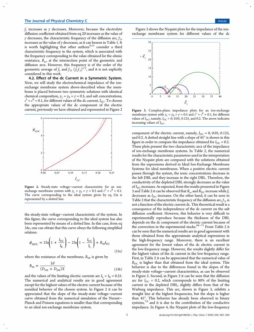
Figure 3 shows the Nyquist plots for the impedance of the ion-exchange membrane system for different values of the dc
component of the electric current, namely, IDC = 0, 0.05, 0.125,and 0.2. A dotted straight line with a slope of 45° is shown in thisfigure in order to compare the impedance obtained for IDC = 0.2.These plots present the two characteristic arcs of the impedanceof ion-exchange membrane systems. In Table 2, the numericalresults for the characteristic parameters used in the interpretationof the Nyquist plots are compared with the solutions obtainedfrom the expressions derived in Ideal Ion-Exchange MembraneSystems for ideal membranes. When a positive electric currentpasses through the system, the ionic concentrations decrease inthe left DBL and they increase in the right DBL. Therefore, theconductivity of the depleted DBL strongly decreases as the valueof IDC increases. As expected, from the results presented in Figure3 and Table 2 it can be observed that Rac and RDC increase while f1decreases as IDC increases. On the other hand, it can be seen inTable 2 that the characteristic frequency of the diffusion arc, f 2, isnot a function of the electric current dc. This theoretical result is aconsequence of the independence of the dc current on the saltdiffusion coefficient. However, this behavior is very difficult toexperimentally reproduce because the thickness of the DBLdepends on the dc component of the electric current because ofthe convection in the experimental stacks.68−71 From Table 2 itcan be seen that the numerical results are in good agreement withthose obtained from the approximate analytical expressions inthe high-frequency range. Moreover, there is an excellentagreement for the lowest values of the dc electric current inthe low-frequency range. However, the results slightly differ forthe highest values of the dc current in the low-frequency range.First, in Table 2 it can be appreciated that the numerical value ofRDC is higher than that obtained from the ideal system. Thisbehavior is due to the differences found in the slopes of thesteady-state voltage−current characteristics, as can be observedin Figure 2. Second, in Figure 3 it can be seen that the diffusionarc for IDC = 0.2, which corresponds to 80% of the limitingcurrent in the depleted DBL, slightly differs from that of theWarburg impedance. This arc, shown in Figure 3, exhibits astraight line at the highest frequencies, but the slope is higherthan 45°. This behavior has already been observed in binarysystems,7,8 and it is due to the contribution of the conductiveimpedance. In Figure 4, the Nyquist plots of the low-frequency
Figure 2. Steady-state voltage−current characteristic for an ion-exchange membrane system with γL = γR = γ = 0.5 and cL = cR = 0.1.The curve corresponding to the ideal system given by eq 53a isrepresented by a dotted line.
Figure 3. Complex-plane impedance plots for an ion-exchangemembrane system with γL = γR = γ = 0.5 and cL = cR = 0.1, for differentvalues of IDC, namely, IDC = 0, 0.05, 0.125, and 0.2. The arrow indicatesincreasing values of IDC.
The Journal of Physical Chemistry C Article
dx.doi.org/10.1021/jp4108238 | J. Phys. Chem. C XXXX, XXX, XXX−XXXI
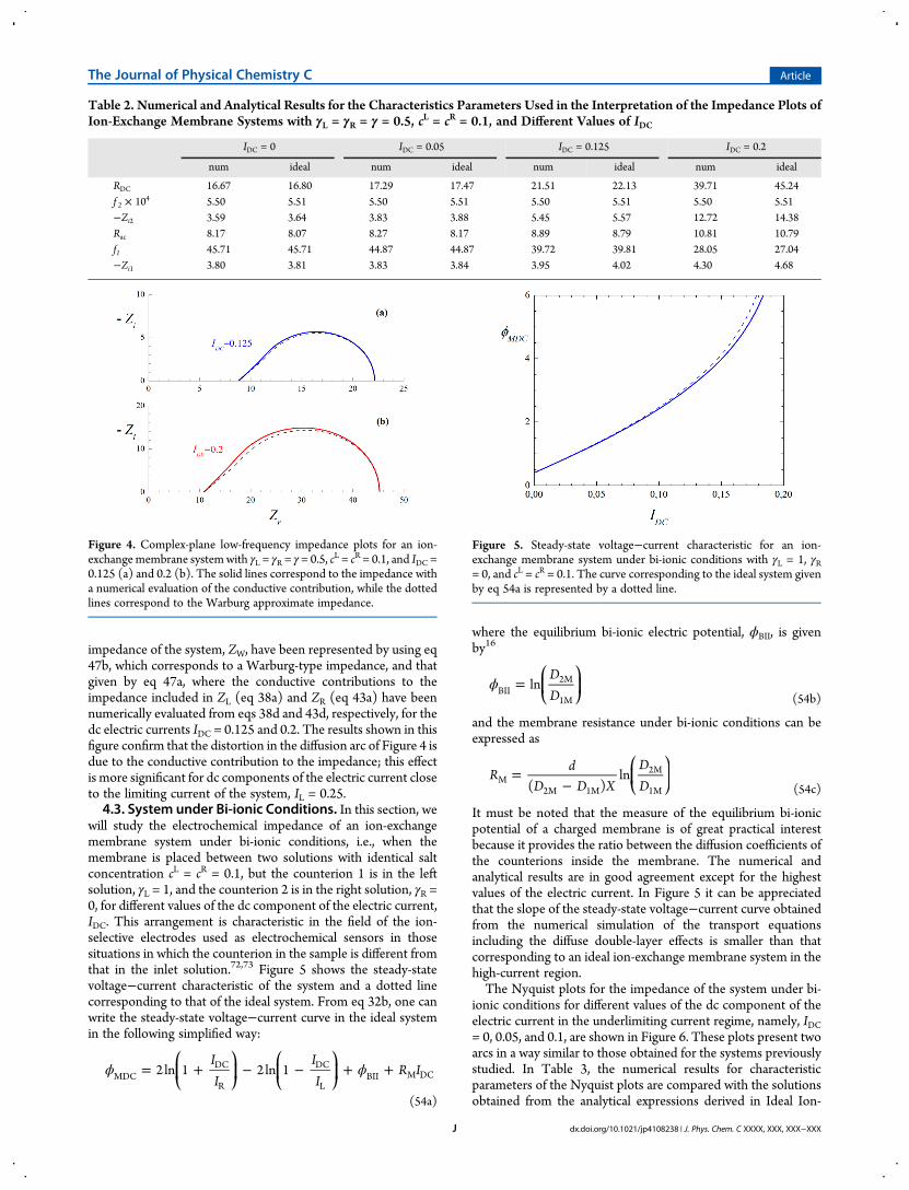
impedance of the system, ZW, have been represented by using eq47b, which corresponds to a Warburg-type impedance, and thatgiven by eq 47a, where the conductive contributions to theimpedance included in ZL (eq 38a) and ZR (eq 43a) have beennumerically evaluated from eqs 38d and 43d, respectively, for thedc electric currents IDC = 0.125 and 0.2. The results shown in thisfigure confirm that the distortion in the diffusion arc of Figure 4 isdue to the conductive contribution to the impedance; this effectis more significant for dc components of the electric current closeto the limiting current of the system, IL = 0.25.4.3. System under Bi-ionic Conditions. In this section, we
will study the electrochemical impedance of an ion-exchangemembrane system under bi-ionic conditions, i.e., when themembrane is placed between two solutions with identical saltconcentration cL = cR = 0.1, but the counterion 1 is in the leftsolution, γL = 1, and the counterion 2 is in the right solution, γR =0, for different values of the dc component of the electric current,IDC. This arrangement is characteristic in the field of the ion-selective electrodes used as electrochemical sensors in thosesituations in which the counterion in the sample is different fromthat in the inlet solution.72,73 Figure 5 shows the steady-statevoltage−current characteristic of the system and a dotted linecorresponding to that of the ideal system. From eq 32b, one canwrite the steady-state voltage−current curve in the ideal systemin the following simplified way:
ϕ ϕ= + − − + +⎛⎝⎜
⎞⎠⎟
⎛⎝⎜
⎞⎠⎟
II
II
R I2 ln 1 2 ln 1MDCDC
R
DC
LBII M DC
(54a)
where the equilibrium bi-ionic electric potential, ϕBII, is givenby16
ϕ =⎛⎝⎜
⎞⎠⎟
DD
lnBII2M
1M (54b)
and the membrane resistance under bi-ionic conditions can beexpressed as
=−
⎛⎝⎜
⎞⎠⎟R
dD D X
DD( )
lnM2M 1M
2M
1M (54c)
It must be noted that the measure of the equilibrium bi-ionicpotential of a charged membrane is of great practical interestbecause it provides the ratio between the diffusion coefficients ofthe counterions inside the membrane. The numerical andanalytical results are in good agreement except for the highestvalues of the electric current. In Figure 5 it can be appreciatedthat the slope of the steady-state voltage−current curve obtainedfrom the numerical simulation of the transport equationsincluding the diffuse double-layer effects is smaller than thatcorresponding to an ideal ion-exchange membrane system in thehigh-current region.The Nyquist plots for the impedance of the system under bi-
ionic conditions for different values of the dc component of theelectric current in the underlimiting current regime, namely, IDC= 0, 0.05, and 0.1, are shown in Figure 6. These plots present twoarcs in a way similar to those obtained for the systems previouslystudied. In Table 3, the numerical results for characteristicparameters of the Nyquist plots are compared with the solutionsobtained from the analytical expressions derived in Ideal Ion-
Table 2. Numerical and Analytical Results for the Characteristics Parameters Used in the Interpretation of the Impedance Plots ofIon-Exchange Membrane Systems with γL = γR = γ = 0.5, cL = cR = 0.1, and Different Values of IDC
IDC = 0 IDC = 0.05 IDC = 0.125 IDC = 0.2
num ideal num ideal num ideal num ideal
RDC 16.67 16.80 17.29 17.47 21.51 22.13 39.71 45.24f 2 × 10⁴ 5.50 5.51 5.50 5.51 5.50 5.51 5.50 5.51−Zi2 3.59 3.64 3.83 3.88 5.45 5.57 12.72 14.38Rac 8.17 8.07 8.27 8.17 8.89 8.79 10.81 10.79f1 45.71 45.71 44.87 44.87 39.72 39.81 28.05 27.04−Zi1 3.80 3.81 3.83 3.84 3.95 4.02 4.30 4.68
Figure 4. Complex-plane low-frequency impedance plots for an ion-exchangemembrane systemwith γL = γR = γ = 0.5, c
L = cR = 0.1, and IDC =0.125 (a) and 0.2 (b). The solid lines correspond to the impedance witha numerical evaluation of the conductive contribution, while the dottedlines correspond to the Warburg approximate impedance.
Figure 5. Steady-state voltage−current characteristic for an ion-exchange membrane system under bi-ionic conditions with γL = 1, γR= 0, and cL = cR = 0.1. The curve corresponding to the ideal system givenby eq 54a is represented by a dotted line.
The Journal of Physical Chemistry C Article
dx.doi.org/10.1021/jp4108238 | J. Phys. Chem. C XXXX, XXX, XXX−XXXJ
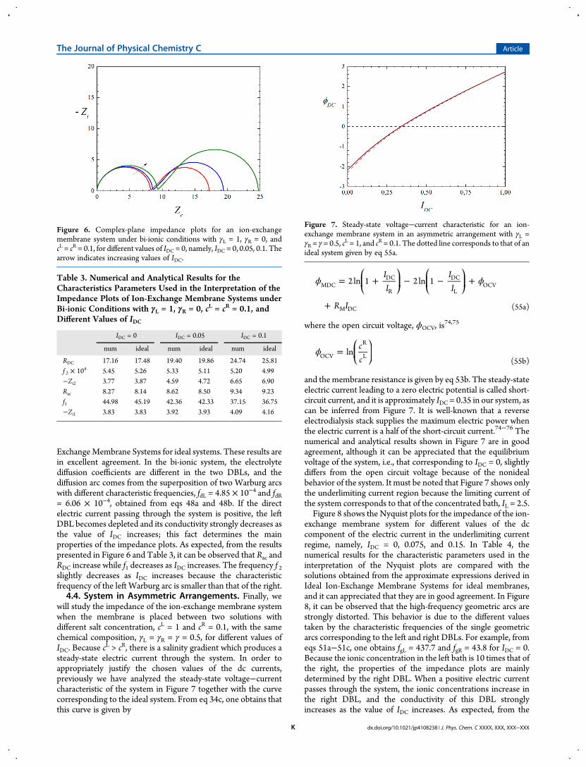
ExchangeMembrane Systems for ideal systems. These results arein excellent agreement. In the bi-ionic system, the electrolytediffusion coefficients are different in the two DBLs, and thediffusion arc comes from the superposition of two Warburg arcswith different characteristic frequencies, fdL = 4.85 × 10⁻⁴ and fdR= 6.06 × 10⁻⁴, obtained from eqs 48a and 48b. If the directelectric current passing through the system is positive, the leftDBL becomes depleted and its conductivity strongly decreases asthe value of IDC increases; this fact determines the mainproperties of the impedance plots. As expected, from the resultspresented in Figure 6 and Table 3, it can be observed that Rac andRDC increase while f1 decreases as IDC increases. The frequency f 2slightly decreases as IDC increases because the characteristicfrequency of the left Warburg arc is smaller than that of the right.4.4. System in Asymmetric Arrangements. Finally, we
will study the impedance of the ion-exchange membrane systemwhen the membrane is placed between two solutions withdifferent salt concentration, cL = 1 and cR = 0.1, with the samechemical composition, γL = γR = γ = 0.5, for different values ofIDC. Because c
L > cR, there is a salinity gradient which produces asteady-state electric current through the system. In order toappropriately justify the chosen values of the dc currents,previously we have analyzed the steady-state voltage−currentcharacteristic of the system in Figure 7 together with the curvecorresponding to the ideal system. From eq 34c, one obtains thatthis curve is given by
ϕ ϕ= + − − +
+
⎛⎝⎜
⎞⎠⎟
⎛⎝⎜
⎞⎠⎟
II
II
R I
2 ln 1 2 ln 1MDCDC
R
DC
LOCV
M DC (55a)
where the open circuit voltage, ϕOCV, is74,75
ϕ =⎛⎝⎜
⎞⎠⎟
cc
lnOCV
R
L(55b)
and the membrane resistance is given by eq 53b. The steady-stateelectric current leading to a zero electric potential is called short-circuit current, and it is approximately IDC = 0.35 in our system, ascan be inferred from Figure 7. It is well-known that a reverseelectrodialysis stack supplies the maximum electric power whenthe electric current is a half of the short-circuit current.74−76 Thenumerical and analytical results shown in Figure 7 are in goodagreement, although it can be appreciated that the equilibriumvoltage of the system, i.e., that corresponding to IDC = 0, slightlydiffers from the open circuit voltage because of the nonidealbehavior of the system. It must be noted that Figure 7 shows onlythe underlimiting current region because the limiting current ofthe system corresponds to that of the concentrated bath, IL = 2.5.Figure 8 shows the Nyquist plots for the impedance of the ion-
exchange membrane system for different values of the dccomponent of the electric current in the underlimiting currentregime, namely, IDC = 0, 0.075, and 0.15. In Table 4, thenumerical results for the characteristic parameters used in theinterpretation of the Nyquist plots are compared with thesolutions obtained from the approximate expressions derived inIdeal Ion-Exchange Membrane Systems for ideal membranes,and it can appreciated that they are in good agreement. In Figure8, it can be observed that the high-frequency geometric arcs arestrongly distorted. This behavior is due to the different valuestaken by the characteristic frequencies of the single geometricarcs corresponding to the left and right DBLs. For example, fromeqs 51a−51c, one obtains fgL = 437.7 and fgR = 43.8 for IDC = 0.Because the ionic concentration in the left bath is 10 times that ofthe right, the properties of the impedance plots are mainlydetermined by the right DBL. When a positive electric currentpasses through the system, the ionic concentrations increase inthe right DBL, and the conductivity of this DBL stronglyincreases as the value of IDC increases. As expected, from the
Figure 6. Complex-plane impedance plots for an ion-exchangemembrane system under bi-ionic conditions with γL = 1, γR = 0, andcL = cR = 0.1, for different values of IDC = 0, namely, IDC = 0, 0.05, 0.1. Thearrow indicates increasing values of IDC.
Table 3. Numerical and Analytical Results for theCharacteristics Parameters Used in the Interpretation of theImpedance Plots of Ion-Exchange Membrane Systems underBi-ionic Conditions with γL = 1, γR = 0, cL = cR = 0.1, andDifferent Values of IDC
IDC = 0 IDC = 0.05 IDC = 0.1
num ideal num ideal num ideal
RDC 17.16 17.48 19.40 19.86 24.74 25.81f 2 × 10⁴ 5.45 5.26 5.33 5.11 5.20 4.99−Zi2 3.77 3.87 4.59 4.72 6.65 6.90Rac 8.27 8.14 8.62 8.50 9.34 9.23f1 44.98 45.19 42.36 42.33 37.15 36.75−Zi1 3.83 3.83 3.92 3.93 4.09 4.16
Figure 7. Steady-state voltage−current characteristic for an ion-exchange membrane system in an asymmetric arrangement with γL =γR = γ = 0.5, c
L = 1, and cR = 0.1. The dotted line corresponds to that of anideal system given by eq 55a.
The Journal of Physical Chemistry C Article
dx.doi.org/10.1021/jp4108238 | J. Phys. Chem. C XXXX, XXX, XXX−XXXK
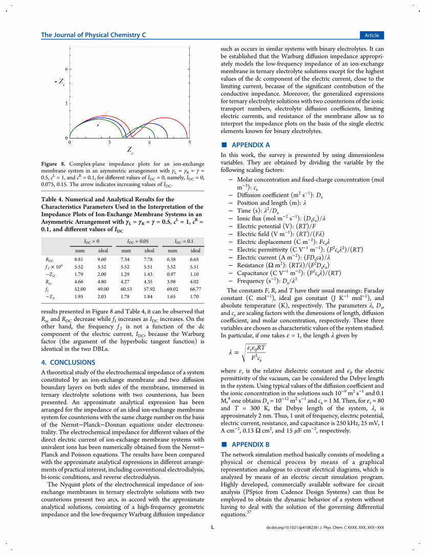
results presented in Figure 8 and Table 4, it can be observed thatRac and RDC decrease while f1 increases as IDC increases. On theother hand, the frequency f 2 is not a function of the dccomponent of the electric current, IDC, because the Warburgfactor (the argument of the hyperbolic tangent function) isidentical in the two DBLs.
4. CONCLUSIONSA theoretical study of the electrochemical impedance of a systemconstituted by an ion-exchange membrane and two diffusionboundary layers on both sides of the membrane, immersed internary electrolyte solutions with two counterions, has beenpresented. An approximate analytical expression has beenarranged for the impedance of an ideal ion-exchange membranesystem for counterions with the same charge number on the basisof the Nernst−Planck−Donnan equations under electroneu-trality. The electrochemical impedance for different values of thedirect electric current of ion-exchange membrane systems withunivalent ions has been numerically obtained from the Nernst−Planck and Poisson equations. The results have been comparedwith the approximate analytical expressions in different arrange-ments of practical interest, including conventional electrodialysis,bi-ionic conditions, and reverse electrodialysis.The Nyquist plots of the electrochemical impedance of ion-
exchange membranes in ternary electrolyte solutions with twocounterions present two arcs, in accord with the approximateanalytical solutions, consisting of a high-frequency geometricimpedance and the low-frequency Warburg diffusion impedance
such as occurs in similar systems with binary electrolytes. It canbe established that the Warburg diffusion impedance appropri-ately models the low-frequency impedance of an ion-exchangemembrane in ternary electrolyte solutions except for the highestvalues of the dc component of the electric current, close to thelimiting current, because of the significant contribution of theconductive impedance. Moreover, the generalized expressionsfor ternary electrolyte solutions with two counterions of the ionictransport numbers, electrolyte diffusion coefficients, limitingelectric currents, and resistance of the membrane allow us tointerpret the impedance plots on the basis of the single electricelements known for binary electrolytes.
■ APPENDIX AIn this work, the survey is presented by using dimensionlessvariables. They are obtained by dividing the variable by thefollowing scaling factors:
− Molar concentration and fixed-charge concentration (molm−3): ca
− Diffusion coefficient (m2 s−1): Da
− Position and length (m): λ− Time (s): λ2/Da
− Ionic flux (mol m−2 s−1): (Daca)/λ− Electric potential (V): (RT)/F− Electric field (V m−1): (RT)/(Fλ)− Electric displacement (C m−2): Fcaλ− Electric permittivity (C V−1 m−1): (F2caλ
2)/(RT)− Electric current (A m−2): (FDaca)/λ− Resistance (Ω m2): (RTλ)/(F2Daca)− Capacitance (C V−1 m−2): (F2caλ)/(RT)− Frequency (s−1): Da/λ
2
The constants F, R, and T have their usual meanings: Faradayconstant (C mol−1), ideal gas constant (J K−1 mol−1), andabsolute temperature (K), respectively. The parameters λ, Da,and ca are scaling factors with the dimensions of length, diffusioncoefficient, and molar concentration, respectively. These threevariables are chosen as characteristic values of the system studied.In particular, if one takes ε = 1, the length λ given by
λε ε
=RT
F cr 0
2a
where εr is the relative dielectric constant and ε0 the electricpermittivity of the vacuum, can be considered the Debye lengthin the system. Using typical values of the diffusion coefficient andthe ionic concentration in the solutions such 10−9 m2 s−1 and 0.1M,4 one obtainsDa = 10
−12 m2 s−1 and ca = 1 M. Then, for εr = 80and T = 300 K, the Debye length of the system, λ, isapproximately 2 nm. Thus, 1 unit of frequency, electric potential,electric current, resistance, and capacitance is 250 kHz, 25 mV, 1A cm−2, 0.13 Ω cm2, and 15 μF cm−2, respectively.
■ APPENDIX BThe network simulation method basically consists of modeling aphysical or chemical process by means of a graphicalrepresentation analogous to circuit electrical diagrams, which isanalyzed by means of an electric circuit simulation program.Highly developed, commercially available software for circuitanalysis (PSpice from Cadence Design Systems) can thus beemployed to obtain the dynamic behavior of a system withouthaving to deal with the solution of the governing differentialequations.37
Figure 8. Complex-plane impedance plots for an ion-exchangemembrane system in an asymmetric arrangement with γL = γR = γ =0.5, cL = 1, and cR = 0.1, for different values of IDC = 0, namely, IDC = 0,0.075, 0.15. The arrow indicates increasing values of IDC.
Table 4. Numerical and Analytical Results for theCharacteristics Parameters Used in the Interpretation of theImpedance Plots of Ion-Exchange Membrane Systems in anAsymmetric Arrangement with γL = γR = γ = 0.5, cL = 1, cR =0.1, and different values of IDC
IDC = 0 IDC = 0.05 IDC = 0.1
num ideal num ideal num ideal
RDC 8.81 9.60 7.34 7.78 6.38 6.65f 2 × 10⁴ 5.52 5.52 5.52 5.51 5.52 5.51−Zi2 1.79 2.00 1.29 1.43 0.97 1.10Rac 4.66 4.80 4.27 4.35 3.98 4.02f1 52.00 49.00 60.53 57.92 69.02 66.77−Zi1 1.95 2.03 1.78 1.84 1.65 1.70
The Journal of Physical Chemistry C Article
dx.doi.org/10.1021/jp4108238 | J. Phys. Chem. C XXXX, XXX, XXX−XXXL
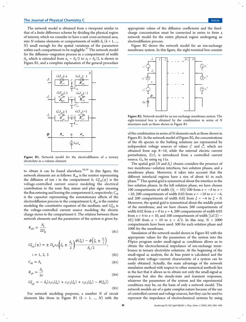
The network model is obtained from a viewpoint similar tothat of a finite difference scheme by dividing the physical regionof interest, which we consider to have a unit cross-sectional area,into N volume elements or compartments of width δk (k = 1, ...,N) small enough for the spatial variations of the parameterswithin each compartment to be negligible.37 The network modelfor the diffusion−migration process in a compartment of widthδk, which is extended from xk − δk/2 to xk + δk/2, is shown inFigure B1, and a complete explanation of the general procedure
to obtain it can be found elsewhere.38,39 In this figure, thenetwork elements are as follows: Rdik is the resistor representingthe diffusion of ion i in the compartment k; GJeik(±) is thevoltage-controlled current source modeling the electricalcontribution to the ionic flux, minus and plus signs meaningthe flux entering and leaving the compartment k, respectively;Cdkis the capacitor representing the nonstationary effects of theelectrodiffusion process in the compartment k; Rpk is the resistormodeling the constitutive equation of the medium; and GJpk isthe voltage-controlled current source modeling the electriccharge stores in the compartment k. The relation between thosenetwork elements and the parameters of the system is given by:
δ=R
D2dikk
ip (B1)
ξδ ϕ ξ ϕ ξ
δ± = ± ±
− ±
=
δ⎛⎝⎜
⎞⎠⎟
( )GJ D z c
i
( )2
( )
/2,
1, 2, 3
eik ip i i kk k k
k
2k
(B2)
δ=Cdk k (B3)
δε
=R2pk
k(B4)
δ ξ ξ ξ θ ξ= − + + −GJ z c z c z c[ ( ) ( ) ( ) ( )]pk k k k k k1 1 2 2 3 3
(B5)
For network modeling purposes, a number N of circuitelements like those in Figure B1 (k = 1, ..., N) with the
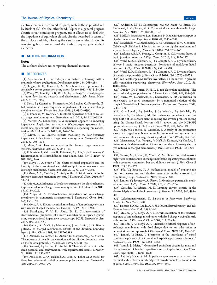
appropriate values of the diffusion coefficients and the fixed-charge concentration must be connected in series to form anetwork model for the entire physical region undergoing anelectrodiffusion process.Figure B2 shows the network model for an ion-exchange
membrane system. In this figure, the eight-terminal box consists
of the combination in series ofN elements such as those shown inFigure B1. In the networkmodel of Figure B2, the concentrationsof the ith species in the bathing solutions are represented byindependent voltage sources of values ci
L and ciR, which are
obtained from eqs 8−10, while the external electric currentperturbation, I(τ), is introduced from a controlled currentsource, GI, by using eq 11a.The spatial grid (N and δk) chosen considers the presence of
two membrane−solution interfaces, two solution phases, and amembrane phase. Moreover, it takes into account that thedifferent interfacial regions have a size of about 4λ in eachphase.45 This spatial grid is symmetrical about the interface in thetwo solution phases. In the left solution phase, we have chosen100 compartments of width (δL − 10)/100 from x = −δ to x =−10, 200 compartments of width 0.03 from x = −10 to x = −4,and 200 compartments of width 0.02 from ξ = −4 to ξ = 0.Moreover, the spatial grid is symmetrical about the middle pointof the membrane, and we have chosen 200 compartments ofwidth 0.02 from x = 0 to x = 4, 200 compartments of width 0.03from x = 4 to x = 10, and 100 compartments of width [(d/2) −10]/100 from x = 10 to x = d/2. In this way, N = 2000compartments have been used: 500 for each solution phase and1000 for the membrane.Simulation of the network model shown in Figure B2 with the
appropriate values for the parameters of the system into thePSpice program under small-signal ac conditions allows us toobtain the electrochemical impedance of ion-exchange mem-branes in ternary electrolyte solutions. At the beginning of thesmall-signal ac analysis, the dc bias point is calculated and thesteady-state voltage−current characteristic of a system can beeasily obtained. Actually, the main advantage of the networksimulation method with respect to other numerical methods liesin the fact that it allows us to obtain not only the small-signal acresponse but also the steady-state and transient responses,whatever the parameters of the system and the experimentalconditions may be, on the basis of only a network model. Thenetwork models are of a quite complex nature because of the useof controlled current and voltage sources, but they can be used torepresent the impedance of electrochemical systems by using
Figure B1. Network model for the electrodiffusion of a ternaryelectrolyte in a volume element.
Figure B2.Network model for an ion-exchange membrane system. Theeight-terminal box is obtained by the combination in series of Nstructures such us those shown in Figure B1.
The Journal of Physical Chemistry C Article
dx.doi.org/10.1021/jp4108238 | J. Phys. Chem. C XXXX, XXX, XXX−XXXM
electric elements distributed in space, such as those pointed outby Buck et al.77 On the other hand, PSpice is a general purposeelectric circuit simulation program, and it allows us to deal withthe impedance of equivalent electric circuits described in terms ofthe Laplace variable, allowing the simulation of electric circuitscontaining both lumped and distributed frequency-dependentelements.
■ AUTHOR INFORMATION
NotesThe authors declare no competing financial interest.
■ REFERENCES(1) Strathmann, H. Electrodialysis: A mature technology with amultitude of new applications. Desalination 2010, 264, 268−288.(2) Logan, B. E.; Elimelech, M. Membrane-based processes forsustainable power generation using water. Nature 1012, 488, 313−319.(3) Wang, W.; Luo, Q.; Li, B.; Wei, X.; Li, L.; Yang, Z. Recent progressin redox flow battery research and development. Adv. Funct. Mater.2013, 23, 970−986.(4) Sistat, P.; Kozmai, A.; Pismenskaya, N.; Larchet, C.; Pourcelly, G.;Nikonenko, V. Low-frequency impedance of an ion-exchangemembrane system. Electrochim. Acta 2008, 53, 6380−6390.(5) Nikonenko, V.; Kozmai, A. Electrical equivalent circuit of an ion-exchange membrane system. Electrochim. Acta 2011, 56, 1262−1269.(6) Mareev, A.; Nikonenko, V. A numerical appoach to modelingimpedance: Application to study a Warburg-type spectrum in amembrane system with diffusion coefficients depending on concen-tration. Electrochim. Acta 2012, 81, 268−274.(7) Moya, A. A. Electric circuits modelling the low-frequencyimpedance of ideal ion-exchange membrane systems. Electrochim. Acta2012, 62, 296−304.(8) Moya, A. A. Harmonic analysis in ideal ion-exchange membranesystems. Electrochim. Acta 2013, 90, 1−11.(9) Rubinstein, I.; Zaltzman, B.; Futerman, A.; Gitis, V.; Nikonenko, V.Reexamination of electrodiffusion time scales. Phys. Rev. E 2009, 79(021506), 1−6.(10) Moya, A. A. Study of the electrochemical impedance and thelinearity of the current−voltage relationship in inhomogeneous ion-exchange membranes. Electrochim. Acta 2010, 55, 2087−2092.(11) Moya, A. A.; Moleon, J. A. Study of the electrical properties of bi-layer ion-exchange membrane systems. J. Electroanal. Chem. 2010, 647,53−59.(12)Moya, A. A. Influence of dc electric current on the electrochemicalimpedance of ion-exchange membrane systems. Electrochim. Acta 2011,56, 3015−3022.(13) Moya, A. A. Electrochemical impedance of ion-exchangemembranes in asymmetric arrangements. J. Electroanal. Chem. 2011,660, 153−162.(14) Moya, A. A. Electrochemical impedance of ion-exchange systemswith weakly charged membranes. Ionics 2013, 19, 1271−1283.(15) Nandigana, V. V. R.; Aluru, N. R. Characterization ofelectrochemical properties of a micro-nanochannel integrated systemusing computational impedance spectroscopy (CIS). Electrochim. Acta2013, 105, 514−523.(16) Guirao, A.; Mafe, S.; Manzanares, J. A.; Ibanez, J. A. Biionicpotential of charged membranes: Effects of the diffusion boundarylayers. J. Phys. Chem. 1995, 99, 3387−3393.(17) Dammak, L.; Larchet, C.; Auclair, B.; Manzanares, J. A.; Mafe, S.The influence of the salt concentration and the difusion boundary layerson the bi-ionic potetial. J. Membr. Sci. 1996, 119, 81−90.(18) Dammak, L.; Larchet, C.; Auclair, B. Theoretical study of the bi-ionic potential and confrontation with experimental results. J. Membr.Sci. 1999, 155, 193−207.(19) Danielsson, C.-O.; Dahlkild, A.; Velin, A.; Behm, M. A model forthe enhanced water dissociation on monopolar membranes. Electrochim.Acta 2009, 54, 2983−2991.
(20) Andersen, M. B.; Soestbergen, M.; van Mani, A.; Bruus, H.;Biesheuvel, P. M.; Bazant, M. Z. Current-induced membrane discharge.Phys. Rev. Lett. 2012, 109 (108301), 1−5.(21)Mafe, S.; Manzanares, J. A.; Ramírez, P. Model for ion transport inbipolar membranes. Phys. Rev. A 1990, 42, 6245−6248.(22) Kovalchuk, V. I.; Zholkovskij, E. K.; Aksenenko, E. V.; Gonzalez-Caballero, F.; Dukhin, S. S. Ionic transport across bipolar membrane andadjacent Nernst layers. J. Membr. Sci. 2006, 284, 255−266.(23) Dickinson, E. J. F.; Freitag, L.; Compton, R. G. Dynamic theory ofliquid junction potentials. J. Phys. Chem. B 2010, 114, 187−197.(24) Ward, K. R.; Dickinson, E. J. F.; Compton, R. G. Dynamic theoryof type 3 liquid junction potentials: Formation of multilayer liquidjunctions. J. Phys. Chem. B 2010, 114, 4521−4528.(25) Ward, K. R.; Dickinson, E. J. F.; Compton, R. G. Dynamic theoryof membrane potentials. J. Phys. Chem. B 2010, 114, 10763−10773.(26) van Soestbergen, M.Diffuse layer effects on the current in galvaniccells containing supporting electrolyte. Electrochim. Acta 2010, 35,1848−1854.(27) Danilov, D.; Notten, P. H. L. Li-ion electrolyte modeling: Theimpact of adding supportive salts. J. Power Sources 2009, 189, 303−308.(28) Kucza, W.; Danielewski, M.; Lewenstam, A. EIS simulations forion-selective site-based membranes by a numerical solution of thecoupled Nernst-Planck-Poisson equations. Electrochem. Commun. 2006,8, 416−420.(29) Grysakowski, B.; Jasielec, J. J.; Wierzba, B.; Solkalski, T.;Lewentam, A.; Danielewski, M. Electrochemical impedance spectros-copy (EIS) of ion sensors direct modeling and inverse problem solvingusing the Nernst-Planck-Poisson (NPP) model and the HGS(FP)optimization strategy. J. Electroanal. Chem. 2011, 662, 143−149.(30) Higa, M.; Tanioka, A.; Miyasaka, K. A study of ion permeationacross a charged membrane in multicomponent ion systems as afunction of membrane charge density. J. Membr. Sci. 1990, 49, 145−169.(31) Manzanares, J. A.; Vergara, J.; Mafe, S.; Kontturi, K.; Viinikka, P.Potentiometric determination of transport numbers of ternary electro-lyte systems in charged membranes. J. Phys. Chem. B 1998, 102, 1301−1307.(32) Tasaka, M.; Kiyono, R.; Yoo, D.-S. Membrane potential across ahigh water content anion-exchange membrane separating two solutionswith a common counterion but two different co-ions. J. Phys. Chem. B1999, 103, 173−177.(33) Fila, V.; Bouzek, K. A mathematical model of multiple iontransport across an ion-selective membrane under current loadconditions. J. Appl. Electrochem. 2003, 33, 675−684.(34) Lanteri, Y.; Szymczyk, A.; Fievet, P. Membrane potential in multi-ionic mixtures. J. Phys. Chem. B 2009, 113, 9197−9204.(35) Geraldes, V.; Afonso, M. D. Limiting current density in theelectrodialysis of multi-ionic solutions. J. Membr. Sci. 2010, 360, 499−508.(36) Lakshminarayanaiah, N. Equations of Membrane Biophysics;Academic: New York, 1984.(37) Bockris, J.O’M. ; Reddy, A. K. N.Modern Electrochemistry, 2nd ed.;Plenum Press: New York, 1998; Vol. 1.(38) Moleon, J. A.; Moya, A. A. Network simulation of the electricalresponse of ion-exchange membranes with fixed charge varying linearlywith position. J. Electroanal. Chem. 2008, 613, 23−34.(39) Moleon, J. A.; Moya, A. A. Transient electrical response of ion-exchange membranes with fixed-charge due to ion adsorption. Anetwork simulation approach. J. Electroanal. Chem. 2009, 633, 306−313.(40) Jamnik, J.; Maier, J. Treatment of the impedance of mixedcondutors equivalent circuit model and explicit approximate solutions. J.Electrochem. Soc. 1999, 146, 4183−4188.(41) Jamnik, J.; Maier, J. Generalised equivalent circuits for mass andcharge transport: Chemical capacitance and its implications. Phys. Chem.Chem. Phys. 2001, 3, 1668−1678.(42) Lai, W.; Haile, S. M. Impedance spectroscopy as a tool forchemical and electrochemical analysis of mixed conductors: A case studyof ceria. J. Am. Ceram. Soc. 2005, 88, 2979−2997.
The Journal of Physical Chemistry C Article
dx.doi.org/10.1021/jp4108238 | J. Phys. Chem. C XXXX, XXX, XXX−XXXN
(43) Lai, W.; Ciucci, F. Small-signal apparent diffusion impedance ofintercalation battery electrodes. J. Electrochem. Soc. 2011, 158, A115−A121.(44) Ciucci, F.; Lai, W. Electrochemical impedance spectroscopy ofphase trasition materials. Electrochim. Acta 2012, 81, 205−215.(45) Manzanares, J. A.; Murphy, W. D.; Mafe, S.; Reiss, H. Numericalsimulation of the nonequilibrium diffuse double layer in ion-exchangemembranes. J. Phys. Chem. 1993, 97, 8524−8530.(46) Moya, A. A.; Horno, J. Application of the network simulationmethod to ionic transport in ion-exchange membranes including diffusedouble-layer effects. J. Phys. Chem. B 1999, 103, 10791−10799.(47) Sokalski, T.; Lingenfelter, P.; Lewenstam, A. Numerical solutionof the coupled Nernst−Planck and Poisson equations for liquid junctionand ion selective membrane potentials. J. Phys. Chem. B 2003, 107,2443−2452.(48) Volgin, V. M.; Davydov, A. D. Ionic transport through ion-exchange and bipolar membranes. J. Membr. Sci. 2005, 259, 110−121.(49) Morf, W. E.; Pretsch, E.; De Rooij, N. F. Computer simulation ofion-selective membrane electrodes and related systems by finite-difference procedures. J. Electroanal. Chem. 2007, 602, 43−54.(50) Brumleve, T. R.; Buck, R. P. Numerical solution of the Nernst-Planck and Poisson equation system with applications to membraneelectrochemistry and solid state physics. J. Eleactroanal. Chem. 1978, 90,1−31.(51) Barsoukov, E.; Macdonald, J. R. Impedance Spectroscopy: Theory,Experiment and Applications; Wiley: New York, 2005.(52) Helfferich, F. Ion Exchange; McGraw-Hill: NY, 1962.(53) Konturri, K.; Murtomaki, L.; Manzanares, J. A. Ionic TransportProcesses in Electrochemistry and Membrane Science; Oxford UniversityPress: New York, 2008.(54) Brumleve, T. R.; Buck, R. P. Transmission line equivalent circuitmodels for electrochemical impedances. J. Electroanal. Chem. 1981, 126,73−104.(55) Pourcelly, G.; Sistat, P.; Chapotot, A.; Gavach, C.; Nikonenko, V.Self diffusion and conductivity in Nafion membranes in contact withNaCl + CaCl2 solutions. J. Membr. Sci. 1996, 110, 69−78.(56) Murata, T.; Tanioka, A. Ion transport across a polyelectrolyte-adsorbed cellulose triacetate membrane in the multicomponent ionicsystems. J. Colloid Interface Sci. 1999, 209, 362−367.(57) Chaudhury, S.; Agarwal, C.; Pandey, A. K.; Goswami, A. Self-diffusion of ions in Nafion-117 membrane having mixed ioniccomposition. J. Phys. Chem. B 2012, 116, 1605−1611.(58) Kim, Y.; Walker, W. S.; Lawler, D. F. Competitive separation of di-vs. mono-valent cations in electrodialysis: Effects of the boundary layerproperties. Water Res. 2012, 46, 2042−2056.(59) Benavente, J.; Zhang, X.; Garcia Valls, R. Modification ofpolysulfone membranes with polyethylene glycol and lignosulfate:Electrical characterization by impedance spectroscopy measurements. J.Colloid Interface Sci. 2005, 285, 273−280.(60) Park, J.-S.; Choi, J.-H.; Woo, J.-J.; Moon, S.-H. An electricalimpedance spectroscopic (EIS) study on transport characteristics of ion-exchange membrane systems. J. Colloid Interface Sci. 2006, 300, 655−662.(61) Dlugolecki, P.; Ogonowski, P.; Metz, S. J.; Saakes, M.; Nijmeijer,K.; Wessling, M. On the resistances of membrane, diffusion boundarylayer and double layer in ion exchange membrane transport. J. Membr.Sci. 2010, 349, 369−379.(62) Zhang, W.; Spichiger, U. E. An impedance study of Mg2+-selectivemembranes. Electrochim. Acta 2000, 45, 2259−2266.(63) Franceschetti, D. R.; Macdonald, J. R.; Buck, R. P. Interpretationof finite-length-Warburg-type impedances in supported and unsup-ported electrochemical cells with kinetically reversible electrodes. J.Electrochem. Soc. 1991, 138, 1368−1371.(64) Jacobsen, T.; West, K. Diffusion impedance in planar, cylindricaland spherical symmetry. Electrochim. Acta 1995, 40, 255−262.(65) Diard, J.-P.; Le Gorrec, B.; Montella, C. Linear diffusionimpedance. General expression and applications. J. Electroanal. Chem.1999, 471, 126−131.
(66) Freger, V. Diffusion impedance and equivalent circuit of amultilayer film. Electrochem. Commun. 2005, 7, 957−961.(67) Bisquert, J.; García-Belmonte, G.; Fabregat-Santiago, F.; Bueno,P. R. Theoretical models for ac impedance of finite diffusion layersexhibiting low frequency dispersion. J. Electroanal. Chem. 1999, 475,152−163.(68) Sistat, P.; Pourcelly, G. Chronopotentiometric response of an ion-exchange membrane in the underlimiting current-range. Transportphenomena within the diffusion layers. J. Membr. Sci. 1997, 123, 121−131.(69) Larchet, C.; Nouri, S.; Auclair, B.; Dammak, L.; Nikonenko, V.Application of chronopotentiometry to determine the thickness ofdiffusion layer adjacent to an ion-exchange membrane under naturalconvection. Adv. Colloid Interface Sci. 2008, 139, 45−61.(70) Kozmai, A. E.; Nikonenko, V. V.; Pismenskaya, N. D.; Mareev, S.A.; Belova, E. I.; Sistat, P. Use of electrochemical impedancespectroscopy for determining the diffusion layer thickness at the surfaceof ion-exchanger membranes. Pet. Chem. 2012, 52, 614−624.(71) Moya, A. A.; Sistat, P. Chronoamperometric response of ion-exchange membrane systems. J. Membr. Sci. 2013, 444, 412−419.(72) Morf, W. E.; Pretsch, E.; De Rooij, N. F. Theoretical treatmentand numerical simulation of potential and concentration profiles inextremely thin non-electroneutral membranes used for ion-selectiveelectrodes. J. Electroanal. Chem. 2010, 641, 45−56.(73) Sokalski, T.; Lewenstam, A. Application of Nernst-Planck andPoisson equations for interpretation of liquid-junction and membranepotentials in real-time and space domains. Electrochem. Commun. 2001,3, 107−112.(74) Post, J. W.; Hamelers, H. V. M.; Buuisman, C. J. N. Energyrecovery from controlled mixing salt and fresh water with a reverseelectrodialysis system. Environ. Sci. Technol. 2008, 42, 5785−5790.(75) Dlugolecki, P.; Gambier, A.; Nijmeier, K.; Wessling, M. Practicalpotential of reverse electrodialysis as process for sustainable energygeneration. Environ. Sci. Technol. 2009, 43, 6888−6894.(76) Vermaas, D. A.; Saakes, M.; Nijmeijer, K. Doubled power densityfrom salinity gradients at reduced intermembrane distance. Environ. Sci.Technol. 2011, 45, 7089−7095.(77) Buck, R. P.; Mundt, C. Aperiodic equivalent circuit for chargepermeable thin-layer cells of symmetric, asymmetric types. J. Chem. Soc.,Faraday Trans. 1996, 92, 3947−3955.
The Journal of Physical Chemistry C Article
dx.doi.org/10.1021/jp4108238 | J. Phys. Chem. C XXXX, XXX, XXX−XXXO