Embed Size (px)
Citation preview
RSC Advances
PAPER
Ope
n A
cces
s A
rtic
le. P
ublis
hed
on 0
5 Se
ptem
ber
2017
. Dow
nloa
ded
on 1
2/5/
2021
4:5
7:24
PM
. T
his
artic
le is
lice
nsed
und
er a
Cre
ativ
e C
omm
ons
Attr
ibut
ion
3.0
Unp
orte
d L
icen
ce.
View Article OnlineView Journal | View Issue
Electromagnetic
aCollege of Chemistry, Chemical Engineering
2999 North Renmin Road, Songjiang Distri
[email protected]; Fax: +86-21-67792608;bState Key Laboratory for Modication of
College of Materials Science and Engineer
China 201620
Cite this: RSC Adv., 2017, 7, 42891
Received 20th July 2017Accepted 21st August 2017
DOI: 10.1039/c7ra08002f
rsc.li/rsc-advances
This journal is © The Royal Society of C
wave absorption polyimide fabricprepared by coating with core–shellNiFe2O4@PANI nanoparticles
Yu Wang,a Wei Wang,a Meifang Zhub and Dan Yu *ab
The nickel ferrite@polyaniline/polyimide (NiFe2O4@PANI/PI) fabric was prepared by coating the PI fabric
with core–shell NiFe2O4@PANI nanoparticles to obtain an excellent microwave absorption performance.
Firstly, a microwave absorbing agent was fabricated by dispersing the pre-synthesized core–shell
NiFe2O4@PANI nanoparticles into epoxy monomer, in which the covalent bonding between epoxy
groups and amine groups from PANI made them uniformly disperse. Then the agent was coated on to
the PI fabric to a thickness of 0.12 mm. The results of field effect-transmission electron microscopy and
scanning electron microscopy demonstrated the core–shell structure of NiFe2O4@PANI and the
composite structure of the NiFe2O4@PANI/PI fabric. The resultant fabric possessed a high microwave
attenuation property with a minimum reflection loss value of �19.2 dB (>90% attenuation) at 16.1 GHz
and the effective absorption bandwidth was 5.1 GHz. This high performance was attributed to the
uniform dispersion of core–shell NiFe2O4@PANI nanoparticles, better impedance matching and intensive
synergistic effect between dielectric loss caused by the PANI shell and magnetic loss from the NiFe2O4
core. The favorable flexibility, processability and high tensile properties gave the composite fabric a long
service time under pressure or foldable conditions. Furthermore, this process was environmentally
friendly as no organic solvent was used in the whole process and the NiFe2O4@PANI/PI fabric could
potentially be applied in microwave absorbing fields.
1. Introduction
The electromagnetic (EM) wave pollution from the proliferationof widespread electronics and instruments not only interruptsthe usual functions of electronic devices but also inuencespeople's health. Therefore, EM wave pollution has been a majorconcern and the worldwide demand for EM shielding textiles inthe electronic and military industries as well as for the use ofprotective garments has increased dramatically because of theirpopular light-weight and exible features.1–4 According to themechanism of EM shielding, EM shielding textiles should havethe capability of reection or absorption. Currently, to reect,those fabrics are mainly prepared by combining fabricswith metals (copper, gold, nickel, silver)5–9 or metalliccompounds10–12 to obtain excellent electrical conductivity,which leads to high EM shielding effectiveness; however, theirapplications are limited because of high processing costs, heavyweight and secondary pollution. To give absorption properties,
and Biotechnology, Donghua University,
ct, Shanghai, PR China 201620. E-mail:
Tel: +86-21-67792456
Chemical Fibers and Polymer Materials,
ing, Donghua University, Shanghai, PR
hemistry 2017
the composite fabrics should have dielectric and/or magneticloss which may be supplied using coating materials possessinghigh permittivity or permeability, for example, carbon materials(carbon nanotubes (CNTs), carbon bers, carbon black, gra-phene, graphite),13–17 conductive polymers (polyaniline (PANI),polypyrrole),18–20 magnetic particles (iron(II,III) (Fe3O4), cobal-t(II,III) oxide (Co3O4), cobalt ferrite (CoFe2O4), nickel ferrite(NiFe2O4), iron(III) oxide (Fe2O3), carbonyl iron)21–26 anddielectric/magnetic hybrid particles,16 all of which allow the EMenergy to be attenuated in the absorbing medium. Nevertheless,many problems have not been solved yet such as poor absorp-tion capacity, narrow absorption band and agglomerationeffects from the EM wave absorbing llers.
Usingmicrowave theory,27 the attenuation of EMwave energycan be accomplished by the reection of the material surface,the absorption and the multiple internal reections from thematerial itself. The entire absorption is an ideal method toattenuate the EM wave energy and now it can be achieved byimproving the impedance matching and enhancing dielectricand magnetic loss. NiFe2O4 has already shown an unparalleledapplication potential in the eld of EMwave absorption becauseof its low production cost, high permeability and permittivity,but its homogenous dispersion in resins is difficult to realizebecause of its poor interfacial compatibility/bonding.27–29
Surface modication is a common method to solve this
RSC Adv., 2017, 7, 42891–42899 | 42891
RSC Advances Paper
Ope
n A
cces
s A
rtic
le. P
ublis
hed
on 0
5 Se
ptem
ber
2017
. Dow
nloa
ded
on 1
2/5/
2021
4:5
7:24
PM
. T
his
artic
le is
lice
nsed
und
er a
Cre
ativ
e C
omm
ons
Attr
ibut
ion
3.0
Unp
orte
d L
icen
ce.
View Article Online
dispersion problem through surfactants30 and polymers.31 PANIhas also been considered as an ideal EM wave absorbingmaterial in coordination with the dielectric loss and improvesthe dispersion of llers because of the presence of amine andimine groups in its structure.19,32,33 Additionally, epoxy resin isusually applied to complement the intrinsic characteristics ofPANI as an EMwave absorbing matrix on account of its low cost,good chemical, mechanical and thermal stabilities.34 Thus,selecting PANI as a medium to make core–shell NiFe2O4@PANInanoparticles, can not only improve the EM absorbing perfor-mance, but also solve the nanoparticles' dispersion problem inepoxy resin because of the chemical bonding of epoxy groupswith amine groups.
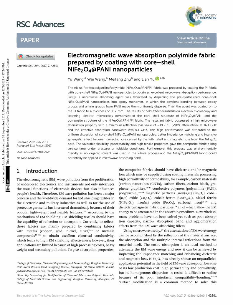
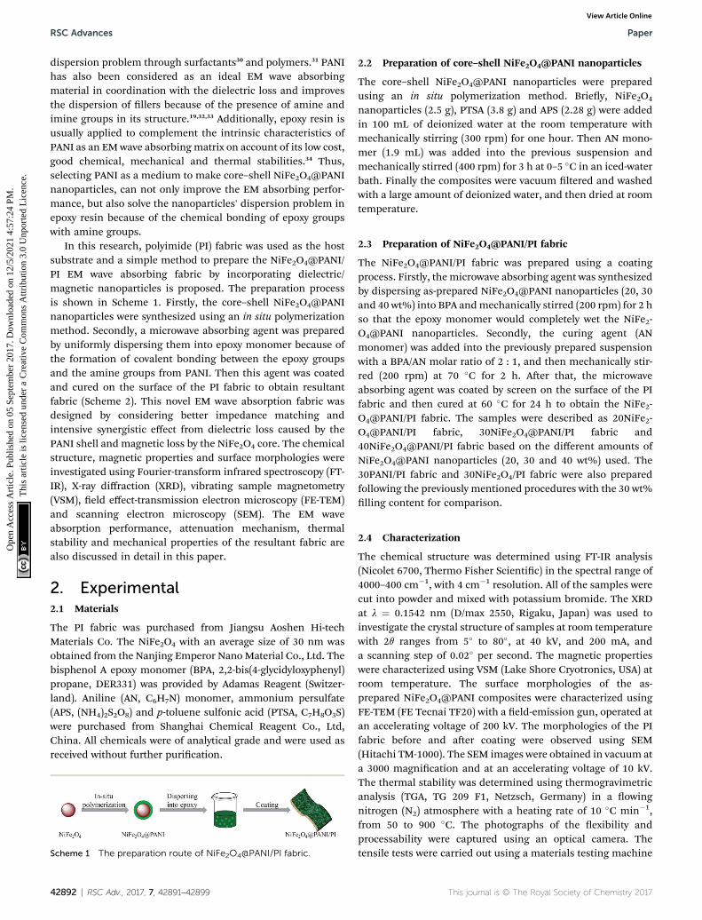
In this research, polyimide (PI) fabric was used as the hostsubstrate and a simple method to prepare the NiFe2O4@PANI/PI EM wave absorbing fabric by incorporating dielectric/magnetic nanoparticles is proposed. The preparation processis shown in Scheme 1. Firstly, the core–shell NiFe2O4@PANInanoparticles were synthesized using an in situ polymerizationmethod. Secondly, a microwave absorbing agent was preparedby uniformly dispersing them into epoxy monomer because ofthe formation of covalent bonding between the epoxy groupsand the amine groups from PANI. Then this agent was coatedand cured on the surface of the PI fabric to obtain resultantfabric (Scheme 2). This novel EM wave absorption fabric wasdesigned by considering better impedance matching andintensive synergistic effect from dielectric loss caused by thePANI shell and magnetic loss by the NiFe2O4 core. The chemicalstructure, magnetic properties and surface morphologies wereinvestigated using Fourier-transform infrared spectroscopy (FT-IR), X-ray diffraction (XRD), vibrating sample magnetometry(VSM), eld effect-transmission electron microscopy (FE-TEM)and scanning electron microscopy (SEM). The EM waveabsorption performance, attenuation mechanism, thermalstability and mechanical properties of the resultant fabric arealso discussed in detail in this paper.
2. Experimental2.1 Materials
The PI fabric was purchased from Jiangsu Aoshen Hi-techMaterials Co. The NiFe2O4 with an average size of 30 nm wasobtained from the Nanjing Emperor Nano Material Co., Ltd. Thebisphenol A epoxy monomer (BPA, 2,2-bis(4-glycidyloxyphenyl)propane, DER331) was provided by Adamas Reagent (Switzer-land). Aniline (AN, C6H7N) monomer, ammonium persulfate(APS, (NH4)2S2O8) and p-toluene sulfonic acid (PTSA, C7H8O3S)were purchased from Shanghai Chemical Reagent Co., Ltd,China. All chemicals were of analytical grade and were used asreceived without further purication.
Scheme 1 The preparation route of NiFe2O4@PANI/PI fabric.
42892 | RSC Adv., 2017, 7, 42891–42899
2.2 Preparation of core–shell NiFe2O4@PANI nanoparticles
The core–shell NiFe2O4@PANI nanoparticles were preparedusing an in situ polymerization method. Briey, NiFe2O4
nanoparticles (2.5 g), PTSA (3.8 g) and APS (2.28 g) were addedin 100 mL of deionized water at the room temperature withmechanically stirring (300 rpm) for one hour. Then AN mono-mer (1.9 mL) was added into the previous suspension andmechanically stirred (400 rpm) for 3 h at 0–5 �C in an iced-waterbath. Finally the composites were vacuum ltered and washedwith a large amount of deionized water, and then dried at roomtemperature.
2.3 Preparation of NiFe2O4@PANI/PI fabric
The NiFe2O4@PANI/PI fabric was prepared using a coatingprocess. Firstly, the microwave absorbing agent was synthesizedby dispersing as-prepared NiFe2O4@PANI nanoparticles (20, 30and 40 wt%) into BPA andmechanically stirred (200 rpm) for 2 hso that the epoxy monomer would completely wet the NiFe2-O4@PANI nanoparticles. Secondly, the curing agent (ANmonomer) was added into the previously prepared suspensionwith a BPA/AN molar ratio of 2 : 1, and then mechanically stir-red (200 rpm) at 70 �C for 2 h. Aer that, the microwaveabsorbing agent was coated by screen on the surface of the PIfabric and then cured at 60 �C for 24 h to obtain the NiFe2-O4@PANI/PI fabric. The samples were described as 20NiFe2-O4@PANI/PI fabric, 30NiFe2O4@PANI/PI fabric and40NiFe2O4@PANI/PI fabric based on the different amounts ofNiFe2O4@PANI nanoparticles (20, 30 and 40 wt%) used. The30PANI/PI fabric and 30NiFe2O4/PI fabric were also preparedfollowing the previously mentioned procedures with the 30 wt%lling content for comparison.
2.4 Characterization
The chemical structure was determined using FT-IR analysis(Nicolet 6700, Thermo Fisher Scientic) in the spectral range of4000–400 cm�1, with 4 cm�1 resolution. All of the samples werecut into powder and mixed with potassium bromide. The XRDat l ¼ 0.1542 nm (D/max 2550, Rigaku, Japan) was used toinvestigate the crystal structure of samples at room temperaturewith 2q ranges from 5� to 80�, at 40 kV, and 200 mA, anda scanning step of 0.02� per second. The magnetic propertieswere characterized using VSM (Lake Shore Cryotronics, USA) atroom temperature. The surface morphologies of the as-prepared NiFe2O4@PANI composites were characterized usingFE-TEM (FE Tecnai TF20) with a eld-emission gun, operated atan accelerating voltage of 200 kV. The morphologies of the PIfabric before and aer coating were observed using SEM(Hitachi TM-1000). The SEM images were obtained in vacuum ata 3000 magnication and at an accelerating voltage of 10 kV.The thermal stability was determined using thermogravimetricanalysis (TGA, TG 209 F1, Netzsch, Germany) in a owingnitrogen (N2) atmosphere with a heating rate of 10 �C min�1,from 50 to 900 �C. The photographs of the exibility andprocessability were captured using an optical camera. Thetensile tests were carried out using a materials testing machine
This journal is © The Royal Society of Chemistry 2017
Scheme 2 The related mechanism of preparation.
Paper RSC Advances
Ope
n A
cces
s A
rtic
le. P
ublis
hed
on 0
5 Se
ptem
ber
2017
. Dow
nloa
ded
on 1
2/5/
2021
4:5
7:24
PM
. T
his
artic
le is
lice
nsed
und
er a
Cre
ativ
e C
omm
ons
Attr
ibut
ion
3.0
Unp
orte
d L
icen
ce.
View Article Online
(H5K-S, Tinius Olsen, USA) according to the Chinese standardGB 9997-88 at 25 �C and 65% relative humidity. Each samplewas tested 10 times and the average value was taken as theresult. The relative complex permittivity (3r ¼ 30 � j300) andrelative complex permeability (mr ¼ m0 � jm00) were tested ona vector network analyzer (Anritsu 37269D, USA) using the waveguide method in the frequency range of 12.4–18.0 GHz. All thetest samples were cut into dimensions of 15.9� 8� 2 mm3. Thereection loss (RL) coefficients and attenuation constant (a)were calculated according to transmission line theory.
3. Results and discussion3.1 Structure and magnetic analysis
The chemical structure was veried using FT-IR spectra andthese are shown in Fig. 1(a). For the neat PANI, the absorptionpeaks at 1580 cm�1 and 1497 cm�1 were attributed to the C]Cstretching vibration of the quinoid ring skeleton (Q) and thebenzenoid ring skeleton (B), respectively. The intensity of thesetwo peaks could give information about the degree of oxidationof the emeraldine form.20 The strong absorption peak at1127 cm�1 was assigned to the B–Q–B stretching vibration,revealing that the conductive form of PANI was present.35 Thepeak at 1299 cm�1 was associated to the C–N stretching vibra-tion of the benzene ring. These absorption peaks (1580, 1497,1299 and 1127 cm�1) were also observed in the spectrum ofNiFe2O4@PANI nanoparticles, but had a slight shi (about 3–8 cm�1) compared with the spectrum of neat PANI, suggestingthat the surface of the NiFe2O4 was successfully functionalizedby the PANI. Additionally, for the cured 30NiFe2O4/epoxy, theabsorption peak around 1235 cm�1 was derived from the C–O–Cstretching vibration which also presented in the spectrum of thecured 30NiFe2O4@PANI/epoxy. Furthermore, it is worth notingthat the terminal epoxy groups were observed at 912 cm�1 in thespectrum of cured 30NiFe2O4/epoxy, but it had nearly dis-appeared in the spectrum of cured 30NiFe2O4@PANI/epoxy.This result could be explained by the fact that the aminegroups with a reactive hydrogen atom from the PANI have
This journal is © The Royal Society of Chemistry 2017
reacted with the epoxy groups, which was benecial to theuniform dispersion of NiFe2O4@PANI nanoparticles in theepoxy resin.
The XRD patterns of NiFe2O4 and NiFe2O4@PANI nano-particles are shown in Fig. 1(b). By comparison, it was clearlyseen that these peaks of NiFe2O4 and NiFe2O4@PANI nano-particles had no signicant difference except for the intensityand all the diffraction peaks were located at 2q¼ 18.64�, 30.49�,35.85�, 37.55�, 43.58�, 53.11�, 57.58�, 63.21� and 75.09�, corre-sponding to the (111), (220), (311), (222), (400), (422), (511),(400) and (533) cubic spinel of NiFe2O4 (JCPDS card no. 10-0325), respectively. The spectra of Fig. 1(a) and (b) conrmedthe coexistence of NiFe2O4 and PANI and suggest that theintroduction of PANI had a negligible inuence on the crystal-line structure of the NiFe2O4 nanoparticles.26 Additionally, it isbelievable that the magnetic properties may be conducive tobalancing the impedance matching condition between thecomplex permittivity and complex permeability.16 So the inves-tigation of magnetic properties plays an important role inunderstanding the EM wave attenuation performance and themagnetic hysteresis loops of NiFe2O4 and NiFe2O4@PANI areshown in Fig. 1(c). As can be seen in Fig. 1(c), both samplesexhibited a typical hysteresis loop in their magnetic behaviorand the saturation magnetization (Ms) values of NiFe2O4 andNiFe2O4@PANI were 36.4 emu g�1 and 28.9 emu g�1, respec-tively. Although the Ms value of NiFe2O4@PANI was slightlydecreased because of the addition of non-magnetic PANI, onbasis of research investigation,16,25 it is believed that the effectsof dispersion improvement and impedance matching conditionoriginating from PANI are important in enhancing the micro-wave absorption. The inset image of Fig. 1(c) shows themagnetic performance of NiFe2O4@PANI nanoparticles, whichcould be attracted when a magnet was placed beside a bottlelled with NiFe2O4@PANI nanoparticles dispersed in deionizedwater. Furthermore, the magnetic hysteresis loops of bothsamples showed an S-like shape and the enlarged magnetiza-tion hysteresis loops are shown in Fig. 1(d), which demonstratesthat the NiFe2O4@PANI maintained the same coercivity (Hc) of
RSC Adv., 2017, 7, 42891–42899 | 42893
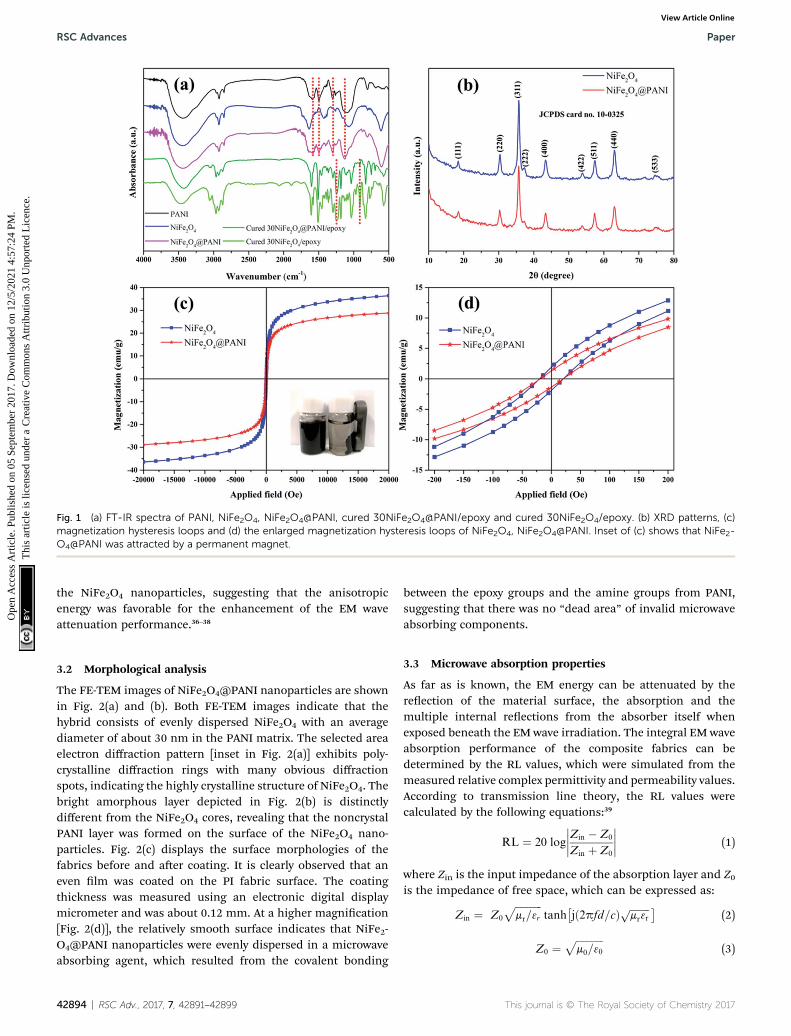
Fig. 1 (a) FT-IR spectra of PANI, NiFe2O4, NiFe2O4@PANI, cured 30NiFe2O4@PANI/epoxy and cured 30NiFe2O4/epoxy. (b) XRD patterns, (c)magnetization hysteresis loops and (d) the enlarged magnetization hysteresis loops of NiFe2O4, NiFe2O4@PANI. Inset of (c) shows that NiFe2-O4@PANI was attracted by a permanent magnet.
RSC Advances Paper
Ope
n A
cces
s A
rtic
le. P
ublis
hed
on 0
5 Se
ptem
ber
2017
. Dow
nloa
ded
on 1
2/5/
2021
4:5
7:24
PM
. T
his
artic
le is
lice
nsed
und
er a
Cre
ativ
e C
omm
ons
Attr
ibut
ion
3.0
Unp
orte
d L
icen
ce.
View Article Online
the NiFe2O4 nanoparticles, suggesting that the anisotropicenergy was favorable for the enhancement of the EM waveattenuation performance.36–38
3.2 Morphological analysis
The FE-TEM images of NiFe2O4@PANI nanoparticles are shownin Fig. 2(a) and (b). Both FE-TEM images indicate that thehybrid consists of evenly dispersed NiFe2O4 with an averagediameter of about 30 nm in the PANI matrix. The selected areaelectron diffraction pattern [inset in Fig. 2(a)] exhibits poly-crystalline diffraction rings with many obvious diffractionspots, indicating the highly crystalline structure of NiFe2O4. Thebright amorphous layer depicted in Fig. 2(b) is distinctlydifferent from the NiFe2O4 cores, revealing that the noncrystalPANI layer was formed on the surface of the NiFe2O4 nano-particles. Fig. 2(c) displays the surface morphologies of thefabrics before and aer coating. It is clearly observed that aneven lm was coated on the PI fabric surface. The coatingthickness was measured using an electronic digital displaymicrometer and was about 0.12 mm. At a higher magnication[Fig. 2(d)], the relatively smooth surface indicates that NiFe2-O4@PANI nanoparticles were evenly dispersed in a microwaveabsorbing agent, which resulted from the covalent bonding
42894 | RSC Adv., 2017, 7, 42891–42899
between the epoxy groups and the amine groups from PANI,suggesting that there was no “dead area” of invalid microwaveabsorbing components.
3.3 Microwave absorption properties
As far as is known, the EM energy can be attenuated by thereection of the material surface, the absorption and themultiple internal reections from the absorber itself whenexposed beneath the EM wave irradiation. The integral EM waveabsorption performance of the composite fabrics can bedetermined by the RL values, which were simulated from themeasured relative complex permittivity and permeability values.According to transmission line theory, the RL values werecalculated by the following equations:39
RL ¼ 20 log
����Zin � Z0
Zin þ Z0
���� (1)
where Zin is the input impedance of the absorption layer and Z0is the impedance of free space, which can be expressed as:
Zin ¼ Z0
ffiffiffiffiffiffiffiffiffiffiffimr=3r
ptanh
�jð2pfd=cÞ ffiffiffiffiffiffiffiffi
mr3rp �
(2)
Z0 ¼ffiffiffiffiffiffiffiffiffiffiffim0=30
p(3)
This journal is © The Royal Society of Chemistry 2017
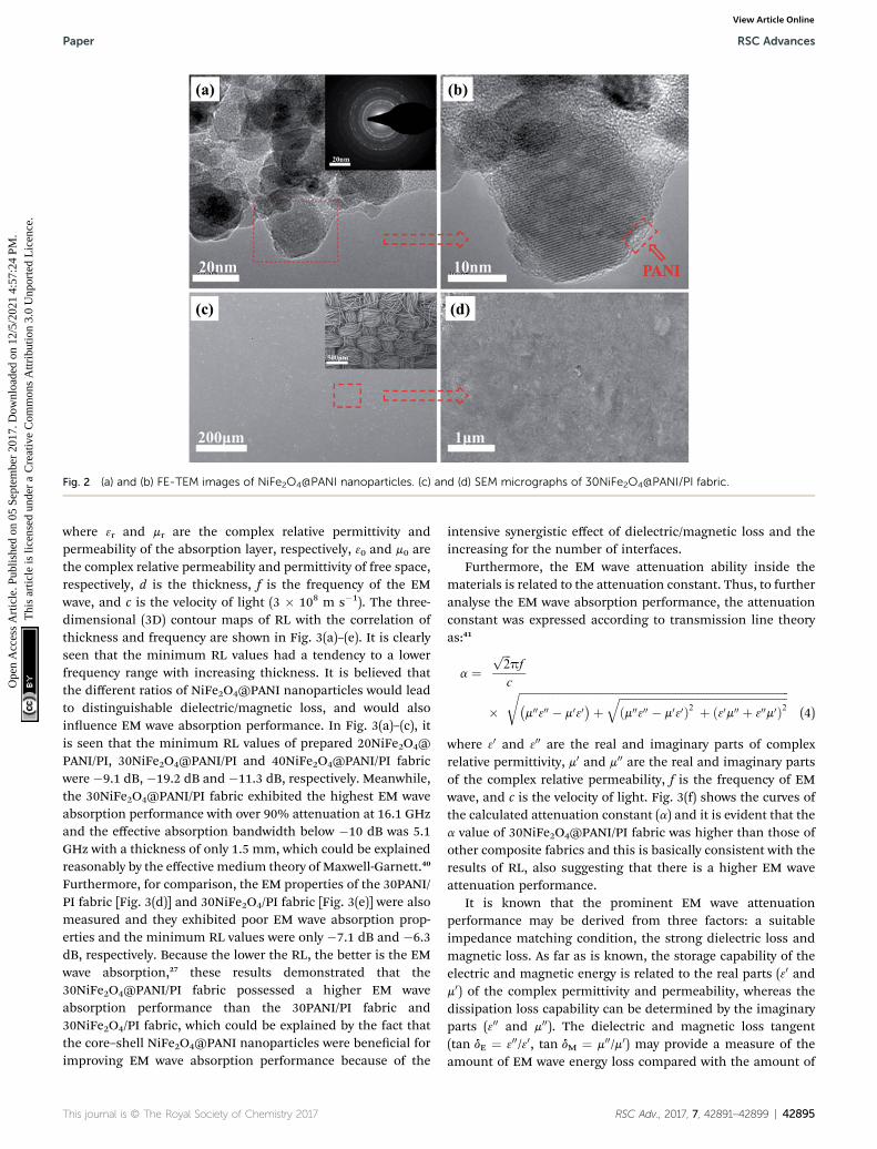
Fig. 2 (a) and (b) FE-TEM images of NiFe2O4@PANI nanoparticles. (c) and (d) SEM micrographs of 30NiFe2O4@PANI/PI fabric.
Paper RSC Advances
Ope
n A
cces
s A
rtic
le. P
ublis
hed
on 0
5 Se
ptem
ber
2017
. Dow
nloa
ded
on 1
2/5/
2021
4:5
7:24
PM
. T
his
artic
le is
lice
nsed
und
er a
Cre
ativ
e C
omm
ons
Attr
ibut
ion
3.0
Unp
orte
d L
icen
ce.
View Article Online
where 3r and mr are the complex relative permittivity andpermeability of the absorption layer, respectively, 30 and m0 arethe complex relative permeability and permittivity of free space,respectively, d is the thickness, f is the frequency of the EMwave, and c is the velocity of light (3 � 108 m s�1). The three-dimensional (3D) contour maps of RL with the correlation ofthickness and frequency are shown in Fig. 3(a)–(e). It is clearlyseen that the minimum RL values had a tendency to a lowerfrequency range with increasing thickness. It is believed thatthe different ratios of NiFe2O4@PANI nanoparticles would leadto distinguishable dielectric/magnetic loss, and would alsoinuence EM wave absorption performance. In Fig. 3(a)–(c), itis seen that the minimum RL values of prepared 20NiFe2O4@PANI/PI, 30NiFe2O4@PANI/PI and 40NiFe2O4@PANI/PI fabricwere �9.1 dB, �19.2 dB and �11.3 dB, respectively. Meanwhile,the 30NiFe2O4@PANI/PI fabric exhibited the highest EM waveabsorption performance with over 90% attenuation at 16.1 GHzand the effective absorption bandwidth below �10 dB was 5.1GHz with a thickness of only 1.5 mm, which could be explainedreasonably by the effective medium theory of Maxwell-Garnett.40
Furthermore, for comparison, the EM properties of the 30PANI/PI fabric [Fig. 3(d)] and 30NiFe2O4/PI fabric [Fig. 3(e)] were alsomeasured and they exhibited poor EM wave absorption prop-erties and the minimum RL values were only �7.1 dB and �6.3dB, respectively. Because the lower the RL, the better is the EMwave absorption,27 these results demonstrated that the30NiFe2O4@PANI/PI fabric possessed a higher EM waveabsorption performance than the 30PANI/PI fabric and30NiFe2O4/PI fabric, which could be explained by the fact thatthe core–shell NiFe2O4@PANI nanoparticles were benecial forimproving EM wave absorption performance because of the
This journal is © The Royal Society of Chemistry 2017
intensive synergistic effect of dielectric/magnetic loss and theincreasing for the number of interfaces.
Furthermore, the EM wave attenuation ability inside thematerials is related to the attenuation constant. Thus, to furtheranalyse the EM wave absorption performance, the attenuationconstant was expressed according to transmission line theoryas:41
a ¼ffiffiffi2
ppf
c
�ffiffiffiffiffiffiffiffiffiffiffiffiffiffiffiffiffiffiffiffiffiffiffiffiffiffiffiffiffiffiffiffiffiffiffiffiffiffiffiffiffiffiffiffiffiffiffiffiffiffiffiffiffiffiffiffiffiffiffiffiffiffiffiffiffiffiffiffiffiffiffiffiffiffiffiffiffiffiffiffiffiffiffiffiffiffiffiffiffiffiffiffiffiffiffiffiffiffi�m00300 � m030
�þffiffiffiffiffiffiffiffiffiffiffiffiffiffiffiffiffiffiffiffiffiffiffiffiffiffiffiffiffiffiffiffiffiffiffiffiffiffiffiffiffiffiffiffiffiffiffiffiffiffiffiffiffiffiffiffiffiffiffiffiffiðm00300 � m030Þ2 þ ð30m00 þ 300m0Þ2
qr(4)
where 30 and 300 are the real and imaginary parts of complexrelative permittivity, m0 and m00 are the real and imaginary partsof the complex relative permeability, f is the frequency of EMwave, and c is the velocity of light. Fig. 3(f) shows the curves ofthe calculated attenuation constant (a) and it is evident that thea value of 30NiFe2O4@PANI/PI fabric was higher than those ofother composite fabrics and this is basically consistent with theresults of RL, also suggesting that there is a higher EM waveattenuation performance.
It is known that the prominent EM wave attenuationperformance may be derived from three factors: a suitableimpedance matching condition, the strong dielectric loss andmagnetic loss. As far as is known, the storage capability of theelectric and magnetic energy is related to the real parts (30 andm0) of the complex permittivity and permeability, whereas thedissipation loss capability can be determined by the imaginaryparts (300 and m00). The dielectric and magnetic loss tangent(tan dE ¼ 300/30, tan dM ¼ m00/m0) may provide a measure of theamount of EM wave energy loss compared with the amount of
RSC Adv., 2017, 7, 42891–42899 | 42895
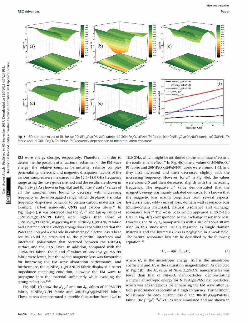
Fig. 3 3D contour maps of RL for (a) 20NiFe2O4@PANI/PI fabric, (b) 30NiFe2O4@PANI/PI fabric, (c) 40NiFe2O4@PANI/PI fabric, (d) 30PANI/PIfabric and (e) 30NiFe2O4/PI fabric. (f) Frequency dependence of the attenuation constants.
RSC Advances Paper
Ope
n A
cces
s A
rtic
le. P
ublis
hed
on 0
5 Se
ptem
ber
2017
. Dow
nloa
ded
on 1
2/5/
2021
4:5
7:24
PM
. T
his
artic
le is
lice
nsed
und
er a
Cre
ativ
e C
omm
ons
Attr
ibut
ion
3.0
Unp
orte
d L
icen
ce.
View Article Online
EM wave energy storage, respectively. Therefore, in order todetermine the possible attenuation mechanism of the EM waveenergy, the relative complex permittivity, relative complexpermeability, dielectric and magnetic dissipation factors of thevarious samples were measured in the 12.4–18.0 GHz frequencyrange using the wave guidemethod and the results are shown inFig. 4(a)–(e). As shown in Fig. 4(a) and (b), the 30 and 300 values ofall the samples were found to decrease with increasingfrequency in the investigated range, which displayed a similarfrequency dispersion behavior to certain carbon materials, forexample, carbon nanocoils, CNTs and carbon bers.42 InFig. 4(a)–(c), it was observed that the 30, 300 and tan dE values of30NiFe2O4@PANI/PI fabric were higher than those of30NiFe2O4/PI fabric, suggesting that 30NiFe2O4@PANI/PI fabrichad a better electrical energy storage/loss capability and that thePANI shell played a vital role in enhancing dielectric loss. Theseresults could be attributed to the plentiful interfaces andinterfacial polarization that occurred between the NiFe2O4
surface and the PANI layer. In addition, compared with the30PANI/PI fabric, the 30 and 300 values of 30NiFe2O4@PANI/PIfabric were lower, but the added magnetic loss was favourablefor improving the EM wave absorption performance, andfurthermore, the 30NiFe2O4@PANI/PI fabric displayed a betterimpedance matching condition, allowing the EM wave topropagate into the material sufficiently while avoiding thestrong reection.43,44
Fig. 4(d)–(f) show the m0, m00 and tan dM values of 30PANI/PIfabric, 30NiFe2O4/PI fabric and 30NiFe2O4@PANI/PI fabric.These curves demonstrated a specic uctuation from 12.4 to
42896 | RSC Adv., 2017, 7, 42891–42899
18.0 GHz, which might be attributed to the small size effect andthe connement effect.45 In Fig. 4(d), the m0 values of 30NiFe2O4/PI fabric and 30NiFe2O4@PANI/PI fabric were around 1.02, andthey rst increased and then decreased slightly with theincreasing frequency. However, for m00 in Fig. 4(e), the valueswere around 0 and then decreased slightly with the increasingfrequency. The negative m00 value demonstrated that themagnetic energy was mainly radiated outwards. It is known thatthe magnetic loss mainly originates from several aspects:hysteresis loss, eddy current loss, domain wall resonance loss(multi-domain materials), natural resonance and exchangeresonance loss.46 The weak peak which appeared at 15.2–18.0GHz in Fig. 4(f) corresponded to the exchange resonance loss.However, the NiFe2O4 nanoparticles with a size of about 30 nmused in this study were usually regarded as single domainmaterials and the hysteresis loss is negligible in a weak eld.The natural resonance loss can be described by the followingequation:47
Ha ¼ 4|K1|/3m0Ms (5)
where Ha is the anisotropic energy, |K1| is the anisotropiccoefficient and Ms is the saturation magnetization. As depictedin Fig. 1(b), the Ms value of NiFe2O4@PANI nanoparticles waslower than that of NiFe2O4 nanoparticles, demonstratinga higher anisotropic energy for NiFe2O4@PANI nanoparticles,which was advantageous for enhancing the EM wave attenua-tion performance especially at a high frequency. Furthermore,to estimate the eddy current loss of the 30NiFe2O4@PANI/PIfabric, the f�1(m0)�2m00 values were simulated and are shown in
This journal is © The Royal Society of Chemistry 2017
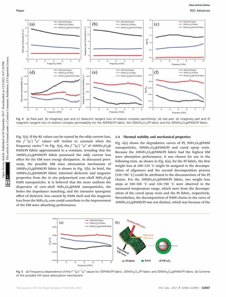
Fig. 4 (a) Real part, (b) imaginary part and (c) dielectric tangent loss of relative complex permittivity, (d) real part, (e) imaginary part and (f)magnetic tangent loss of relative complex permeability for the 30PANI/PI fabric, the 30NiFe2O4/PI fabric and the 30NiFe2O4@PANI/PI fabric.
Paper RSC Advances
Ope
n A
cces
s A
rtic
le. P
ublis
hed
on 0
5 Se
ptem
ber
2017
. Dow
nloa
ded
on 1
2/5/
2021
4:5
7:24
PM
. T
his
artic
le is
lice
nsed
und
er a
Cre
ativ
e C
omm
ons
Attr
ibut
ion
3.0
Unp
orte
d L
icen
ce.
View Article Online
Fig. 5(a). If the RL values can be caused by the eddy current loss,the f�1(m0)�2m00 values will incline to constant when thefrequency varies.21 In Fig. 5(a), the f�1(m0)�2m00 of 30NiFe2O4@PANI/PI fabric approximated to a constant, revealing that the30NiFe2O4@PANI/PI fabric possessed the eddy current losseffect for the EM wave energy dissipation. As discussed previ-ously, the possible EM wave attenuation mechanism of30NiFe2O4@PANI/PI fabric is shown in Fig. 5(b). In brief, the30NiFe2O4@PANI/PI fabric inherited dielectric and magneticproperties from the in situ polymerized core–shell NiFe2O4@PANI nanoparticles. It is believed that the more uniform thedispersion of core–shell NiFe2O4@PANI nanoparticles, thebetter the impedance matching, and the intensive synergisticeffect of dielectric loss caused by PANI shell and the magneticloss from the NiFe2O4 core could contribute to the improvementof the EM wave absorbing performance.
Fig. 5 (a) Frequency dependence of the f�1(m0)�2m00 values for 30PANI/PIof the possible EM wave attenuation mechanism.
This journal is © The Royal Society of Chemistry 2017
3.4 Thermal stability and mechanical properties
Fig. 6(a) shows the degradation curves of PI, NiFe2O4@PANInanoparticles, 30NiFe2O4@PANI/PI and cured epoxy resin.Because the 30NiFe2O4@PANI/PI fabric had the highest EMwave absorption performance, it was chosen for use in thefollowing tests. As shown in Fig. 6(a), for the PI fabric, the rstweight loss at 200–230 �C might be assigned to the decompo-sition of oligomers and the second decomposition process(550–700 �C) could be attributed to the disconnection of the PIchains. For the 30NiFe2O4@PANI/PI fabric, two weight losssteps at 300–500 �C and 550–700 �C were observed in themeasured temperature range, which were from the decompo-sition of the cured epoxy resin and the PI fabric, respectively.Nevertheless, the decomposition of PANI chains in the curve of30NiFe2O4@PANI/PI was not distinct, which was because of the
fabric, 30NiFe2O4/PI fabric and 30NiFe2O4@PANI/PI fabric. (b) Scheme
RSC Adv., 2017, 7, 42891–42899 | 42897
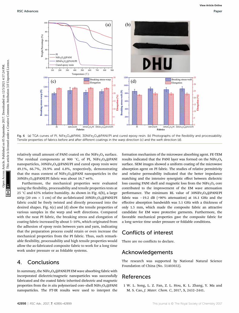
Fig. 6 (a) TGA curves of PI, NiFe2O4@PANI, 30NiFe2O4@PANI/PI and cured epoxy resin. (b) Photographs of the flexibility and processability.Tensile properties of fabrics before and after different coatings in the warp direction (c) and the weft direction (d).
RSC Advances Paper
Ope
n A
cces
s A
rtic
le. P
ublis
hed
on 0
5 Se
ptem
ber
2017
. Dow
nloa
ded
on 1
2/5/
2021
4:5
7:24
PM
. T
his
artic
le is
lice
nsed
und
er a
Cre
ativ
e C
omm
ons
Attr
ibut
ion
3.0
Unp
orte
d L
icen
ce.
View Article Online
relatively small amount of PANI coated on the NiFe2O4 surface.The residual components at 900 �C, of PI, NiFe2O4@PANInanoparticles, 30NiFe2O4@PANI/PI and cured epoxy resin were49.1%, 66.7%, 39.9% and 4.8%, respectively, demonstratingthat the mass content of NiFe2O4@PANI nanoparticles in the30NiFe2O4@PANI/PI fabric was about 16.7 wt%.
Furthermore, the mechanical properties were evaluatedusing the exibility, processability and tensile properties tests at25 �C and 65% relative humidity. As shown in Fig. 6(b), a largestrip (20 cm � 5 cm) of the as-fabricated 30NiFe2O4@PANI/PIfabric could be freely twisted and directly processed into thedesired shapes. Fig. 6(c) and (d) show the tensile properties ofvarious samples in the warp and we directions. Comparedwith the neat PI fabric, the breaking stress and elongation ofcoating fabric increased by about 5–10%, which originated fromthe adhesion of epoxy resin between yarn and yarn, indicatingthat the preparation process could retain or even increase themechanical properties from the PI fabric. Thus, such remark-able exibility, processability and high tensile properties wouldallow the as-fabricated composite fabric to work for a long timework under pressure or as foldable systems.
4. Conclusions
In summary, the NiFe2O4@PANI/PI EMwave absorbing fabric withincorporated dielectric/magnetic nanoparticles was successfullyfabricated and the coated fabric inherited dielectric and magneticproperties from the in situ polymerized core–shell NiFe2O4@PANInanoparticles. The FT-IR results were used to interpret the
42898 | RSC Adv., 2017, 7, 42891–42899
formationmechanism of the microwave absorbing agent. FE-TEMresults indicated that the PANI layer was formed on the NiFe2O4
surface. SEM images showed a uniform coating of the microwaveabsorption agent on PI fabric. The studies of relative permittivityand relative permeability indicated that the better impedancematching and the intensive synergistic effect between dielectricloss causing PANI shell and magnetic loss from the NiFe2O4 corecontributed to the improvement of the EM wave attenuationperformance. The minimum RL value of 30NiFe2O4@PANI/PIfabric was �19.2 dB (>90% attenuation) at 16.1 GHz and theeffective absorption bandwidth was 5.1 GHz with a thickness ofonly 1.5 mm, which made the composite fabric an attractivecandidate for EM wave protective garments. Furthermore, thefavorable mechanical properties gave the composite fabric fora long service time under pressure or foldable conditions.
Conflicts of interest
There are no conicts to declare.
Acknowledgements
The research was supported by National Natural ScienceFoundation of China (No. 51403032).
References
1 W. L. Song, L. Z. Fan, Z. L. Hou, K. L. Zhang, Y. Ma andM. S. Cao, J. Mater. Chem. C, 2017, 5, 2432–2441.
This journal is © The Royal Society of Chemistry 2017
Paper RSC Advances
Ope
n A
cces
s A
rtic
le. P
ublis
hed
on 0
5 Se
ptem
ber
2017
. Dow
nloa
ded
on 1
2/5/
2021
4:5
7:24
PM
. T
his
artic
le is
lice
nsed
und
er a
Cre
ativ
e C
omm
ons
Attr
ibut
ion
3.0
Unp
orte
d L
icen
ce.
View Article Online
2 A. Haji, R. S. Rahbar and A. M. Shoushtari, Appl. Surf. Sci.,2014, 311, 593–601.
3 S. T. Hsiao, C. C. Ma, W. H. Liao, Y. S. Wang, S. M. Li,Y. C. Huang, R. B. Yang and W. F. Liang, ACS Appl. Mater.Interfaces, 2014, 6, 10667–10678.
4 K. Cheng, S. Ramakrishna and K. Lee, Composites, Part A,2000, 31, 1039–1045.
5 Y. Lu, L. Xue and F. Li, Appl. Surf. Sci., 2011, 257, 3135–3139.6 D. Yu, W. Li, W. Wang and J. Zhang, Fibers Polym., 2015, 16,23–30.
7 S. Mu, H. Xie, W. Wang and D. Yu, Appl. Surf. Sci., 2015, 353,608–614.
8 M. S. Ozen, E. Sancak, N. Soin, T. H. Shah and E. Siores, J.Text. Inst., 2015, 107, 912–922.
9 S. Bi, H. Zhao, L. Hou and Y. Lu, Appl. Surf. Sci., 2017, 419,465–475.
10 M. Ramesan, Polym. Eng. Sci., 2014, 54, 438–445.11 X.-S. Hu, Y. Shen, L.-H. Xu, L.-M. Wang, L.-s. Lu and
Y.-t. Zhang, Appl. Surf. Sci., 2016, 385, 162–170.12 C. Y. Lee, D. E. Lee, C. K. Jeong, Y. K. Hong, J. H. Shim, J. Joo,
M. S. Kim, J. Y. Lee, S. H. Jeong and S. W. Byun, Polym. Adv.Technol., 2002, 13, 577–583.
13 Y. Yang, M. C. Gupta, K. L. Dudley and R. W. Lawrence, NanoLett., 2005, 5, 2131–2134.
14 C. Feng, X. Liu, Y. Sun, C. Jin and Y. Lv, RSC Adv., 2014, 4,22710–22715.
15 S. Das, G. Nayak, S. Sahu, P. Routray, A. Roy and H. Baskey, J.Eng., 2014, 2014.
16 J. Fang, Z. Chen, W. Wei, Y. Li, T. Liu, Z. Liu, X. Yue andZ. Jiang, RSC Adv., 2015, 5, 50024–50032.
17 Z. Lu, L. Ma, J. Tan, H. Wang and X. Ding, Nanoscale, 2016, 8,16684–16693.
18 M. S. Kim, H. K. Kim, S. W. Byun, S. H. Jeong, Y. K. Hong,J. S. Joo, K. T. Song, J. K. Kim, C. J. Lee and J. Y. Lee,Synth. Met., 2002, 126, 233–239.
19 X. D. Yang, K. Q. Lei and J. Y. Hu, Russ. J. Appl. Chem., 2014,87, 909–915.
20 D. Chen, Y. E. Miao and T. Liu, ACS Appl. Mater. Interfaces,2013, 5, 1206–1212.
21 J. Wang, H. Zhou, J. Zhuang and Q. Liu, Phys. Chem. Chem.Phys., 2015, 17, 3802–3812.
22 Z. Guo, S. E. Lee, H. Kim, S. Park, H. T. Hahn, A. B. Karki andD. P. Young, Acta Mater., 2009, 57, 267–277.
23 X. Huang, J. Zhang, Z. Liu, T. Sang, B. Song, H. Zhu andC. Wong, J. Alloys Compd., 2015, 648, 1072–1075.
24 J. Feng, F. Pu, Z. Li, X. Li, X. Hu and J. Bai, Carbon, 2016, 104,214–225.
This journal is © The Royal Society of Chemistry 2017
25 W.-p. Li, L.-q. Zhu, J. Gu and H.-c. Liu, Composites, Part B,2011, 42, 626–630.
26 M. Fu, Q. Jiao and Y. Zhao, J. Mater. Chem. A, 2013, 1, 5577–5586.
27 S. P. Pawar, M. Gandi and S. Bose, RSC Adv., 2016, 6, 37633–37645.
28 W. Wang, C. Zang and Q. Jiao, J. Magn. Magn. Mater., 2015,378, 261–266.
29 L. Li, G. Li, R. L. Smith and H. Inomata, Chem. Mater., 2000,12, 3705–3714.
30 X. Wang, C. Zhang, X. Wang and H. Gu, Appl. Surf. Sci., 2007,253, 7516–7521.
31 Y. Kang and T. A. Taton, J. Am. Chem. Soc., 2003, 125, 5650–5651.
32 P. Saini, V. Choudhary, N. Vijayan and R. Kotnala, J. Phys.Chem. C, 2012, 116, 13403–13412.
33 P. Liu, Y. Huang, J. Yan and Y. Zhao, J. Mater. Chem. C, 2016,4, 6362–6370.
34 W. Yang, S. Yu, R. Sun and R. Du, Ceram. Int., 2012, 38, 3553–3562.
35 D. Yu, Y. Wang, T. Hao, W. Wang and B. Liu, J. Ind. Text.,2017, 1–15.
36 J. Guo, X. Wang, P. Miao, X. Liao, W. Zhang and B. Shi, J.Mater. Chem., 2012, 22, 11933–11942.
37 J. Zhu, S. Wei, N. Haldolaarachchige, D. P. Young andZ. Guo, J. Phys. Chem. C, 2011, 115, 15304–15310.
38 X. Li, J. Feng, H. Zhu, C. Qu, J. Bai and X. Zheng, RSC Adv.,2014, 4, 33619–33625.
39 Y. Sun, J. Xu, W. Qiao, X. Xu, W. Zhang, K. Zhang, X. Zhang,X. Chen, W. Zhong and Y. Du, ACS Appl. Mater. Interfaces,2016, 8, 31878–31886.
40 J. V. Mantese, A. L. Micheli, D. F. Dungan, R. G. Geyer,J. Baker-Jarvis and J. Grosvenor, J. Appl. Phys., 1996, 79,1655–1660.
41 L. Yuan, L. Xiangxuan, L. Rong, W. Wu andW. Xuanjun, RSCAdv., 2015, 5, 8713–8720.
42 Y. Du, W. Liu, R. Qiang, Y. Wang, X. Han, J. Ma and P. Xu,ACS Appl. Mater. Interfaces, 2014, 6, 12997–13006.
43 W.-L. Song, X.-T. Guan, L.-Z. Fan, Y.-B. Zhao, W.-Q. Cao,C.-Y. Wang and M.-S. Cao, Carbon, 2016, 100, 109–117.
44 J. Liu, R. Che, H. Chen, F. Zhang, F. Xia, Q. Wu andM.Wang,Small, 2012, 8, 1214–1221.
45 H. Wang, Z. Yan, J. An, J. He, Y. Hou, H. Yu, N. Ma, G. Yu andD. Sun, RSC Adv., 2016, 6, 92152–92158.
46 Y. Wang, W. Wang and D. Yu, Appl. Surf. Sci., 2017, 425, 518–525.
47 J.-Q. Zhu, X.-J. Zhang, S.-W. Wang, G.-S. Wang and P.-G. Yin,RSC Adv., 2016, 6, 88104–88109.
RSC Adv., 2017, 7, 42891–42899 | 42899