Embed Size (px)
Citation preview
Technology Student AssociationNational Conference and Competitions
Electronic Research and Experimentation
Internet Controlled Robotic Arm
Baltimore, MarylandJune 28 – July 2, 2010
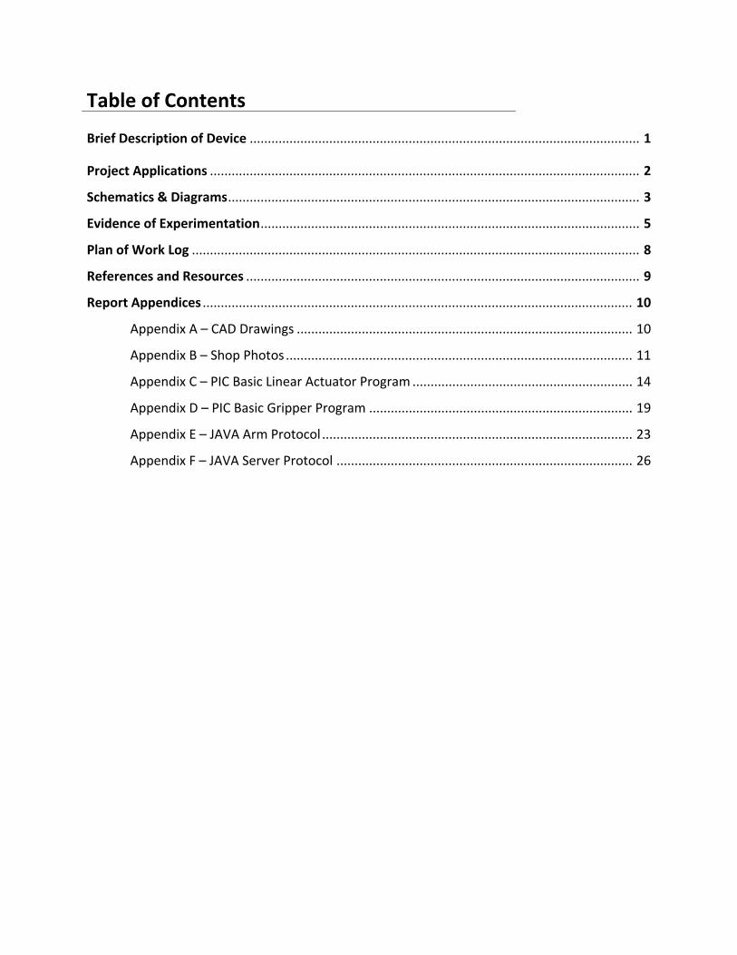
Table of Contents
Brief Description of Device ............................................................................................................ 1
Project Applications ....................................................................................................................... 2
Schematics & Diagrams .................................................................................................................. 3
Evidence of Experimentation ......................................................................................................... 5
Plan of Work Log ............................................................................................................................ 8
References and Resources ............................................................................................................. 9
Report Appendices ....................................................................................................................... 10
Appendix A – CAD Drawings ............................................................................................. 10
Appendix B – Shop Photos ................................................................................................ 11
Appendix C – PIC Basic Linear Actuator Program ............................................................. 14
Appendix D – PIC Basic Gripper Program ......................................................................... 19
Appendix E – JAVA Arm Protocol ...................................................................................... 23
Appendix F – JAVA Server Protocol .................................................................................. 26
Page 1
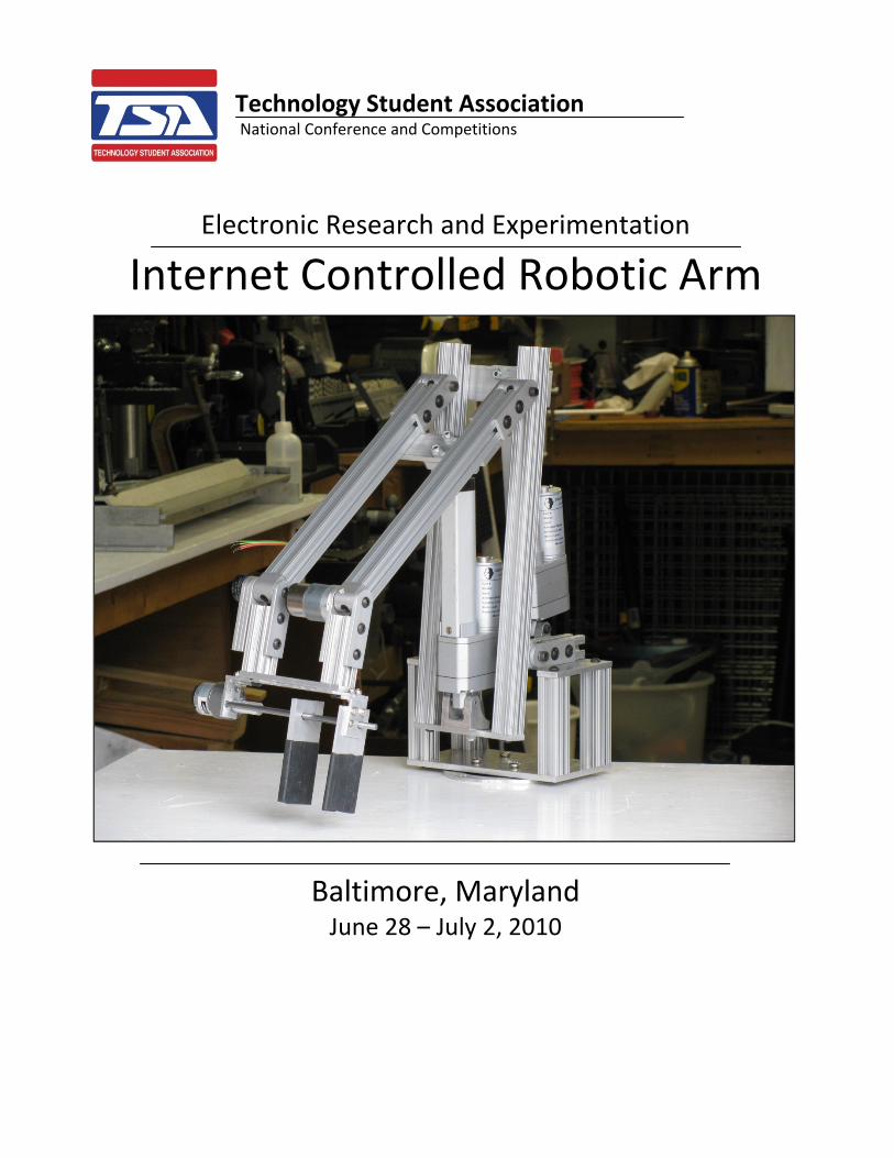
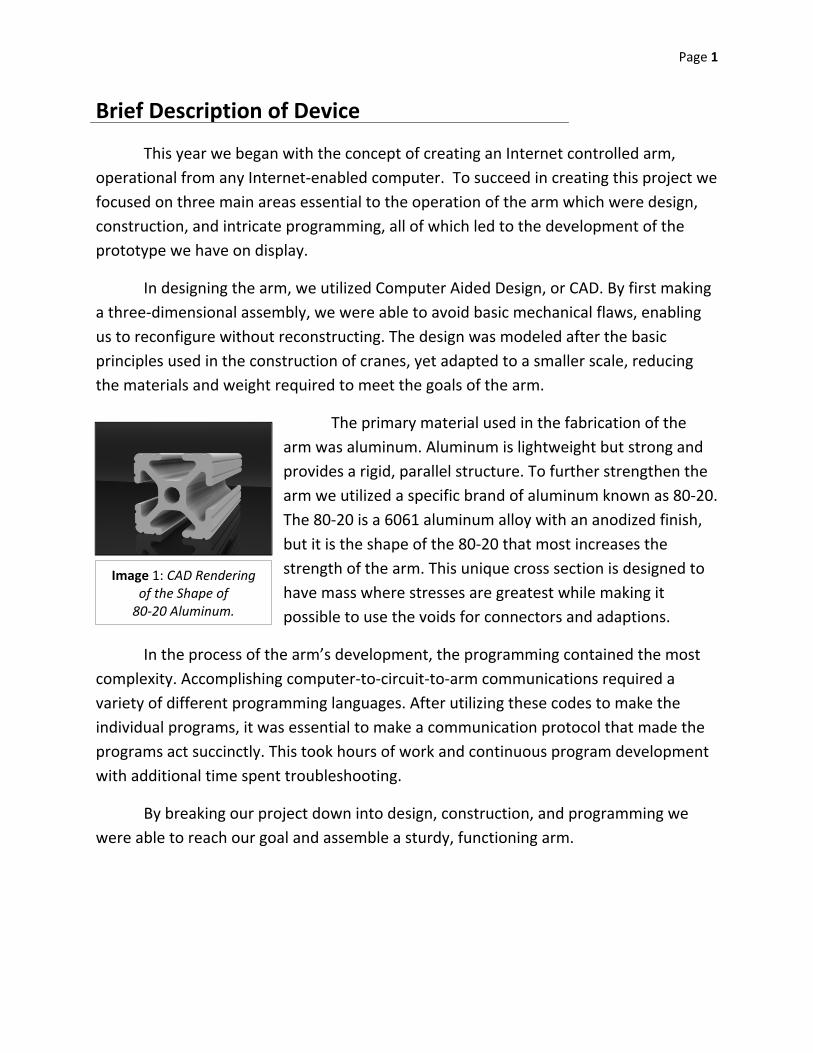
Image 1: CAD Rendering of the Shape of 80‐20 Aluminum.
Brief Description of Device
This year we began with the concept of creating an Internet controlled arm,
operational from any Internet‐enabled computer. To succeed in creating this project we
focused on three main areas essential to the operation of the arm which were design,
construction, and intricate programming, all of which led to the development of the
prototype we have on display.
In designing the arm, we utilized Computer Aided Design, or CAD. By first making
a three‐dimensional assembly, we were able to avoid basic mechanical flaws, enabling
us to reconfigure without reconstructing. The design was modeled after the basic
principles used in the construction of cranes, yet adapted to a smaller scale, reducing
the materials and weight required to meet the goals of the arm.
The primary material used in the fabrication of the
arm was aluminum. Aluminum is lightweight but strong and
provides a rigid, parallel structure. To further strengthen the
arm we utilized a specific brand of aluminum known as 80‐20.
The 80‐20 is a 6061 aluminum alloy with an anodized finish,
but it is the shape of the 80‐20 that most increases the
strength of the arm. This unique cross section is designed to
have mass where stresses are greatest while making it
possible to use the voids for connectors and adaptions.
In the process of the arm’s development, the programming contained the most
complexity. Accomplishing computer‐to‐circuit‐to‐arm communications required a
variety of different programming languages. After utilizing these codes to make the
individual programs, it was essential to make a communication protocol that made the
programs act succinctly. This took hours of work and continuous program development
with additional time spent troubleshooting.
By breaking our project down into design, construction, and programming we
were able to reach our goal and assemble a sturdy, functioning arm.

Page 2
Project Applications
Mechanical arms are a basic necessity in many robotic applications. A functional
robot is usually equipped with some sort of arm that utilizes a gripper or a claw device,
enabling the robot to accomplish a wider variety of different tasks. From this starting
point there were several different applications for an Internet controlled robotic arm.
It was immediately apparent that this kind of robot would be ideally suited for
several different types of medical applications. When we began researching, we found
several examples of robots capable of precise movements while being controlled
remotely from a distance. This would allow specialists in particular surgeries to be able
to perform out‐of‐country operations without even having to leave their location. This
could provide more immediate results for many different types of surgeries.
In commercial industries, this kind of robot would be extremely useful with a
human interface. It would be very lucrative for international manufacturers to have a
robot that could be controlled from a distance from the actual area of production. This
would allow wireless access to the robot and bypass hazards in areas unsafe to humans.
It would also allow for centralization of industrial processors which increases efficiency
in production. Industrial applications and designs could vary, but the basic idea of
Internet communication would be valuable and effective.
Whether via satellite, hard line, or Wi‐Fi, the Internet is accessible from almost
anywhere on the planet. It is because of this availability that the Internet has grown so
swiftly and facilitated many technological advances. By utilizing the Internet’s
capabilities, we will be able to control this robot from almost anywhere in the world to
accomplish a variety of specialized applications.
Page 3
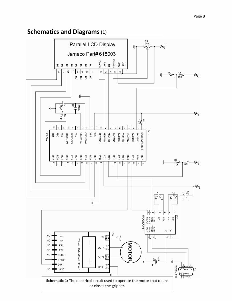
Schematic 1: The electrical circuit used to operate the motor that opens or closes the gripper.
Schematics and Diagrams (1)
Page 4
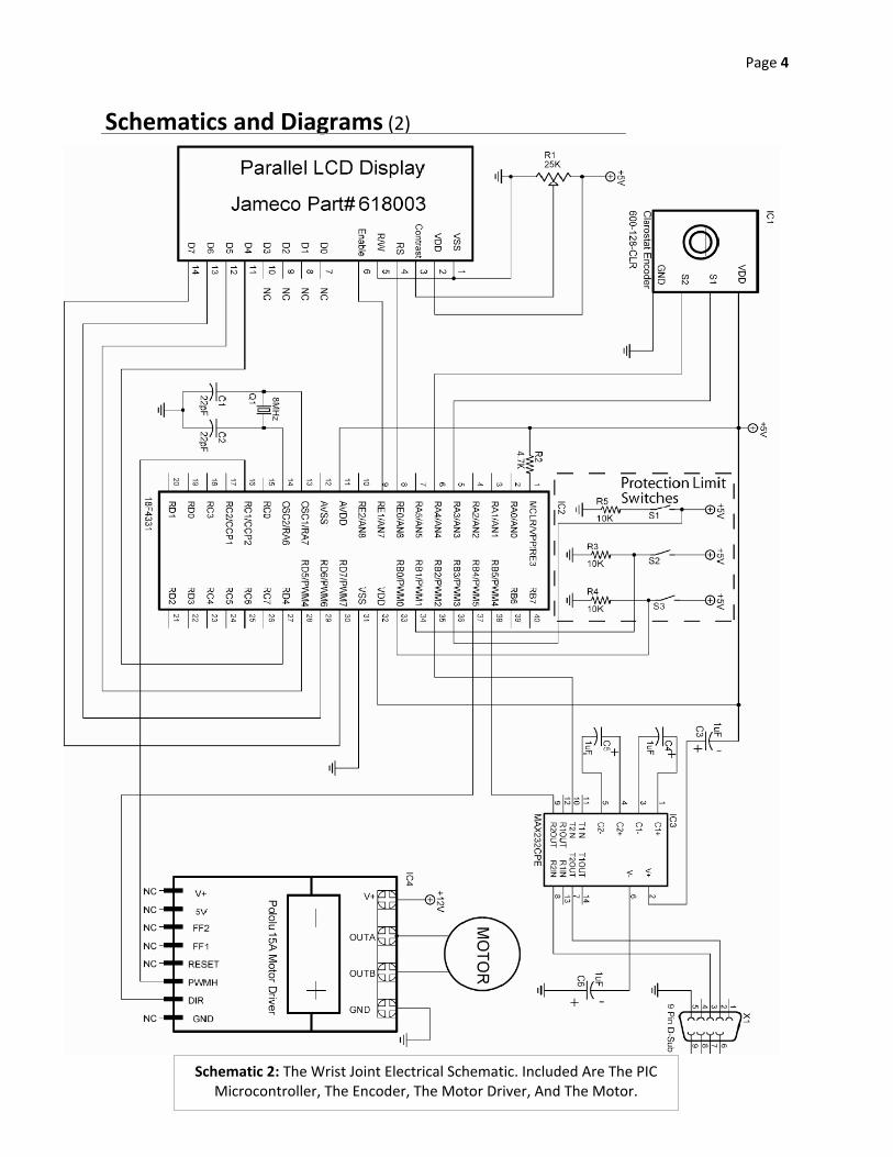
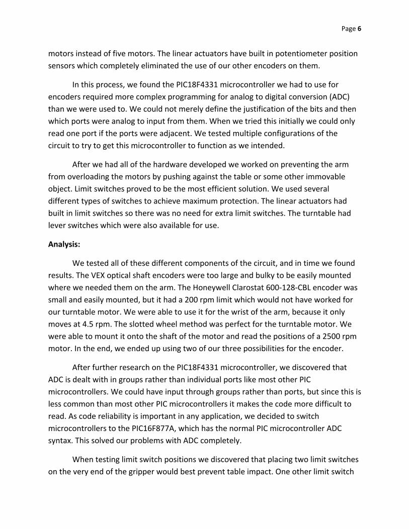
Schematic 2: The Wrist Joint Electrical Schematic. Included Are The PIC Microcontroller, The Encoder, The Motor Driver, And The Motor.
Schematics and Diagrams (2)

Page 5
Evidence of Experimentation
Components:
The circuit of the Internet arm consists of several types of components that
interact with each other to make the arm move. The first component is the brains of the
arm which consists of four Programmable Integrated Circuits, or PIC Microcontrollers.
Another type is the MAX32CPE RS‐232 serial driver/receiver which lets the PIC
microcontrollers receive commands from the server. The third type of component in the
circuit is the motor drivers. These permit the PIC microcontroller to move the motors.
The final type of component of the arm is the position sensors and limit switches. These
allow the PIC microcontrollers to detect the positions of the motors and prevent the
arm from injuring itself.
These components interact in various ways. When the circuit sends commands to
the server, the server sends this to the RS232 integrated circuit (IC). The RS232 IC
receives commands from the server and forwards them to PIC microcontroller. The
microcontroller then moves the motors in the correct direction, using the position
sensors to keep track of how much they have moved and how much further they have
to go. If while the motors are moving one of the limit switches is triggered, the arm
ceases its movements and waits for a command to reverse.
Ideas and Testing:
When constructing the circuit initially, we did not know which sensors we would
be using. This led to experimenting with the different types of sensors and
microcontrollers to fit these sensors. The first sensor with which we experimented was
the position sensor. We also had to experiment with different PIC microcontrollers to fit
our position sensors. Finally we experimented with limit switches and their placement
for complete motor overload protection. In our initial mechanical design we intended to
use motors at each joint, which would only require rotational sensing. In order to detect
the position of each motor we chose to use quadrature encoder position sensors. As
different encoders have different resolutions, we had to experiment with several
different models to determine which best fit our needs. We had three different models
of encoders to test. The first was a VEX optical shaft encoder. We also had a Honeywell
Clarostat 600‐128‐CBL encoder and finally a few 48 slot encoder wheels and readers for
them. This resulted in a design change to use two linear actuators and three normal
Page 6
motors instead of five motors. The linear actuators have built in potentiometer position
sensors which completely eliminated the use of our other encoders on them.
In this process, we found the PIC18F4331 microcontroller we had to use for
encoders required more complex programming for analog to digital conversion (ADC)
than we were used to. We could not merely define the justification of the bits and then
which ports were analog to input from them. When we tried this initially we could only
read one port if the ports were adjacent. We tested multiple configurations of the
circuit to try to get this microcontroller to function as we intended.
After we had all of the hardware developed we worked on preventing the arm
from overloading the motors by pushing against the table or some other immovable
object. Limit switches proved to be the most efficient solution. We used several
different types of switches to achieve maximum protection. The linear actuators had
built in limit switches so there was no need for extra limit switches. The turntable had
lever switches which were also available for use.
Analysis:
We tested all of these different components of the circuit, and in time we found
results. The VEX optical shaft encoders were too large and bulky to be easily mounted
where we needed them on the arm. The Honeywell Clarostat 600‐128‐CBL encoder was
small and easily mounted, but it had a 200 rpm limit which would not have worked for
our turntable motor. We were able to use it for the wrist of the arm, because it only
moves at 4.5 rpm. The slotted wheel method was perfect for the turntable motor. We
were able to mount it onto the shaft of the motor and read the positions of a 2500 rpm
motor. In the end, we ended up using two of our three possibilities for the encoder.
After further research on the PIC18F4331 microcontroller, we discovered that
ADC is dealt with in groups rather than individual ports like most other PIC
microcontrollers. We could have input through groups rather than ports, but since this is
less common than most other PIC microcontrollers it makes the code more difficult to
read. As code reliability is important in any application, we decided to switch
microcontrollers to the PIC16F877A, which has the normal PIC microcontroller ADC
syntax. This solved our problems with ADC completely.
When testing limit switch positions we discovered that placing two limit switches
on the very end of the gripper would best prevent table impact. One other limit switch

Page 7
was necessary to detect when the gripper was fully open, and two more were needed to
prevent the wrist from over extending itself. The linear actuators had built‐in limit
switches and the turntable switches proved to be the most convenient and fortunately
were placed such that they could be soldered to without any modification. Mounting
separate limit switches would have been far more complicated to mount and less cost
effective.

Page 8
Plan of Work Log Date Task & Comments Time Team
9/10/2009‐9/21/2009
We worked on CAD designs for the arm, we sketched the connecting base plates for the joints on Solidworks. Also
included was a Delrin CAD. The main components we selected were aluminum, delrin, and 80/20 because of their
light weight and strength. We began GUI encoder programming, changed an osscilator out. We made a simple GUI
with Swing JAVA
6 Hours
King
Shepard
Sorrels
Spencer
10/8/2009 Completed part two of the rotational base for the internet arm. We also worked on a second gripper prototype. 3 HoursKing
Shepard
10/26/2009‐10/29/2009
We started the server‐side Java program, creating comunication protocol. Working on serial communication with
the PIC microcontroller. We are currently using a socket to communicate over a LAN. We worked further on the
user side communications (GUI) for the internet arm. We established new panels and began layout, but had
difficulty with the layout. We redrilled and remounted the base motor. Also, the platform was cut to regulation
size, and two 30 degree angles were cut to fit the posterboard. We worked further on serial communications and
learned how to identify necassary ports.
6.5 Hours
King
Shepard
Spencer
11/19/2009 We succesfully programmed serial communication link to operate servo 3 Hours Spencer
12/7/2009‐12/10/2009
Testing: we were able to turn a servo motor via PIC microcontroller, and also flash an LED on and off from a PC. We
assembled three main segment joints with modified hinges and created a skeleton frame of the arm on Solidworks
and finished CAD work of the main table. We outputted the motor encoder target PIC microcontrollers from the PC.
A motor controller H‐bridge was blown out.
8.5 Hours
King
Shepard
Sorrels
Spencer
12/14/2009‐12/17/09
We fixed the motor drivers and worked on outputting integers over a LAN.We worked on designing CAD variations
of the pulley design, for operating the arm. We successfully outputted a 16‐bit number over the network to
command a motor with an encoder. We were able to report the position back to the server.
5.5 hours
King
Shepard
Spencer
1/7/2010‐1/14/2010
CAD designs continue to change, while the GUI and socket communication work continued. We constructed the
base of the arm based on the CAD. From this a physical testing prototype was constructed. A motor position was
outputted to a PIC microcontroller, but are having difficulties with multiple command strings.
10 Hours
King
Shepard
Spencer
1/18/2010‐1/21/2010We are having continuing problems with command strings, however have come close to solving it. Two motors now
work with PIC Microcontrollers6.5 Hours Spencer
1/25/2010‐1/28/2010
We have finally decided to switche the pulley system with linear actuators. The reduces PIC Micrcontrollers to two
and two serial communicators. We have encoutered difficulties with which we can find no solution thus are
continuing testing.
5.5 HoursShepard
Spencer
2/1/2010‐2/4/2010 We made design changes to account for the change to linear actuators. The CAD model was updated for changes. 5.5 Hours Spencer
2/8/2010‐2/12/2010 The computer we had been using for Pic Basic Programming had an unknown glitch when compiling. 6.5 Hours Spencer
2/15/2010‐2/18/2010 New serial ports were installed for more motor communication, and server protocol was made for receiving 7 Hours Spencer
2/22/2010‐2/25/2010We mounted the third section of the arm on CAD and constructed the segment. Encountered Macro error with
motor communication that has not been solved yet6.5 Hours
King
Spencer
3/1/2010‐3/4/2010The arm base was completed and cooling fans were added to the base for colling the electronics. The gripper for
the arm, a leadscrew system, was mounted to the arm7 Hours
Shepard
Spencer
3/8/2010‐3/11/2010The final circuit was completed, but burned two LCDs out with high amperage. The fram of the arm with motors is
completed, now we are placing sensors on specific areas of the arm.8 Hours
Shepard
Spencer
3/15/2010‐3/18/2010 The finalised circuit was debugged and commands from computer work. We wired limit switches on the arm. 6 Hours Spencer
3/22/2010‐3/25/2010 Added astetics to the arm and worked on encoder brackts. 4.5 Hours Shepard
4/1/2010‐4/6/2010 Completed encoder and shaft brackets, set upt testing prototypes. Wrist limit switches programmed. 6 Hours Shepard
4/8/2010‐4/12/2010 Created brackets for specialised limit switches on the end of the arm and mounted on gripper plate 6 HoursKing
Spencer
4/13/2010‐4/18/2010 Began final documentation and poster, while programming limit switches and making final changes 7 HoursKing
Spencer
4/19/2010‐4/21/2010 Finalised the poster and technical report for the State Conference 10 Hours King
5/3/2010‐5/10/2010Began work on the transition from LAN communication to Internet communication. We researched webcams for
use on the arm, and ordered 3 Microsoft LifeCam Cinema webcams to begin experimenting with8 Hours
King
Spencer
5/10/2010‐5/17/2010Continued work on programming changes from LAN to Internet communication and also began work on the final
housing for the arm inside of our shop. 7.5 Hours Spencer
5/17/2010‐5/24/2010
Successfully were able to control two of the motors of the arm over the internet. Received a new leadscrew for the
gripper of the arm and adapted it to our existing gripper. This resulted in higher speed and a smoother running
gripper
7 Hours
King
Shepard
Spencer
5/24/2010‐5/31/2010
Were completely able to control the arm over the internet utilising the GUI. Now we have begun work on
incoporating webcams into the GUI for remote control over the internet. The gripper is finished and work has
begun again on the final housing of the arm
7.5 Hours
King
Shepard
Spencer
6/1/2010‐6/8/2010
We began testing with webcams using JMF studio and FMJ studio; media java programs, possibly being adapted to
transmit our webcams. However it can not trnasmit webcams that utilise the same driver, which means we must
purchase two other webcams of different manufaturers.
8.5 Hours Spencer
6/8/2010‐6/15/2010We have finished the final housing of the arm in the shop. We have stopped using JMF and FMJ studios and are
writing our own programs, since these two programs are outdated, and non compatible.10 Hours
King
Shepard
Spencer
6/15/2010‐6/22/2010Have made two webcams function over the GUI as well as reconfirmed that the arm works over the internet. We
have begun working on documentation and posters; updating them from the state versions.12 Hours
King
Shepard
Spencer
Page 9
References
Honeywell Sensing and Control. (2006). Clarostat encoder data sheet. Retrieved
June 26, 2010, from: http://www.alliedelec.com/Images/Products/
Datasheets/BM/CLAROSTAT/CLAROSTAT_INDUSTRIAL‐CONTROL_
7530059.PDF
LTI‐Civil. (2007). Overview package class library. Retrieved June 26,2010, from:
http://lti‐civil.org/doc/index.html
MicroEngineering. Labs, Inc. (2005). PICBASIC PRO compiler. Colorado Springs,
CO: microEngineering Labs, Inc.
Sun Microsystems. (2010a). The really big index. Retrieved June 26, 2010 from:
http://java.sun.com/docs/books/tutorial/reallybigindex.html
Sun Microsystems. (2010b). Java 6 API specification library. Retrieved June 26,
2010, from: http://java.sun.com/javase/6/docs/api/
Resources
Dr. Tim Davis, University Professor of Computer Sciences
David Kundinger, Senior, Mechanical Engineering
Chris Kennedy, Senior, Aeronautical Engineering
Page 10
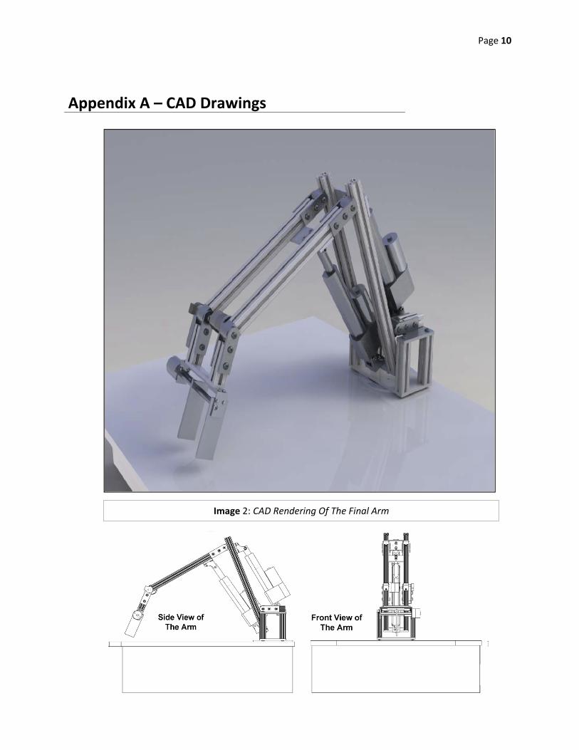
Image 2: CAD Rendering Of The Final Arm
Appendix A – CAD Drawings
Page 11
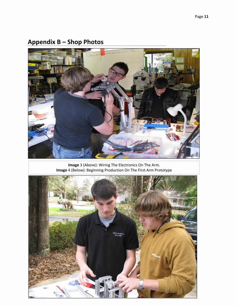
Image 3 (Above): Wiring The Electronics On The Arm. Image 4 (Below): Beginning Production On The First Arm Prototype
Appendix B – Shop Photos
Page 12
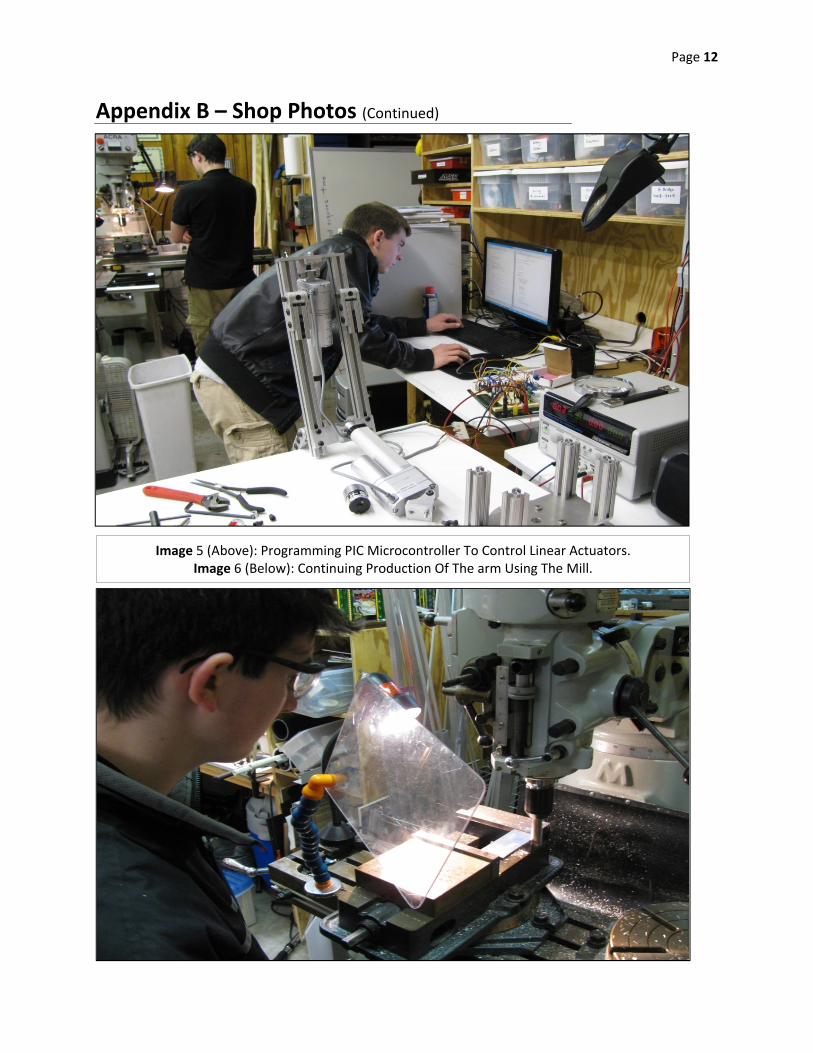
Image 5 (Above): Programming PIC Microcontroller To Control Linear Actuators. Image 6 (Below): Continuing Production Of The arm Using The Mill.
Appendix B – Shop Photos (Continued)
Page 13
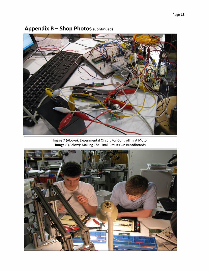
Image 7 (Above): Experimental Circuit For Controlling A Motor Image 8 (Below): Making The Final Circuits On Breadboards
Appendix B – Shop Photos (Continued)
Page 14
Appendix C – Linear Actuator Program
Page 15
Appendix C – Linear Actuator Program (Continued)
Page 16
Appendix C – Linear Actuator Program (Continued)
Page 17
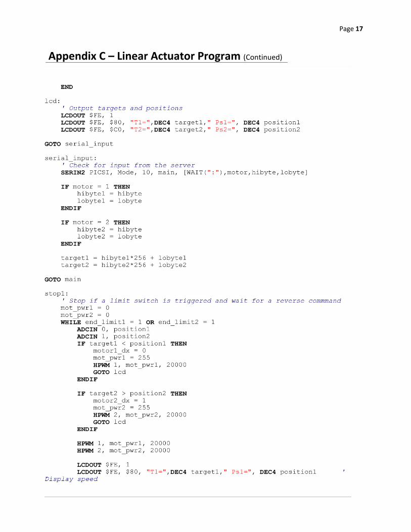
Appendix C – Linear Actuator Program (Continued)
Page 18
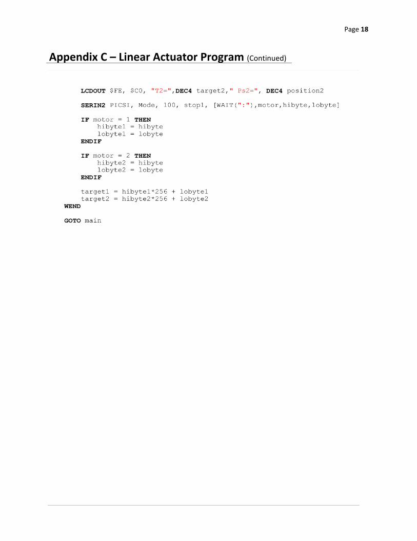
Appendix C – Linear Actuator Program (Continued)
Page 19
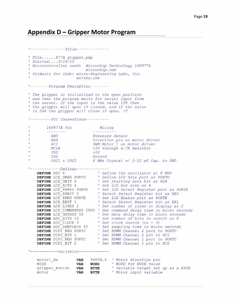
Appendix D – Gripper Motor Program
Page 20
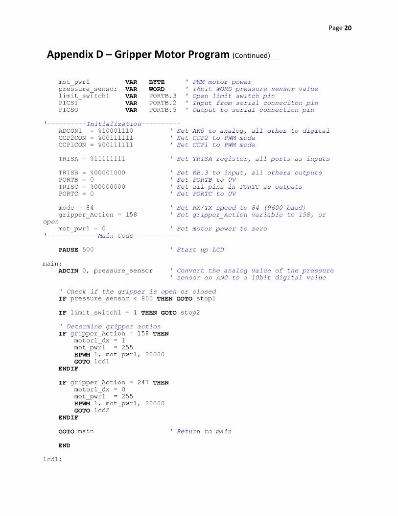
Appendix D – Gripper Motor Program (Continued)
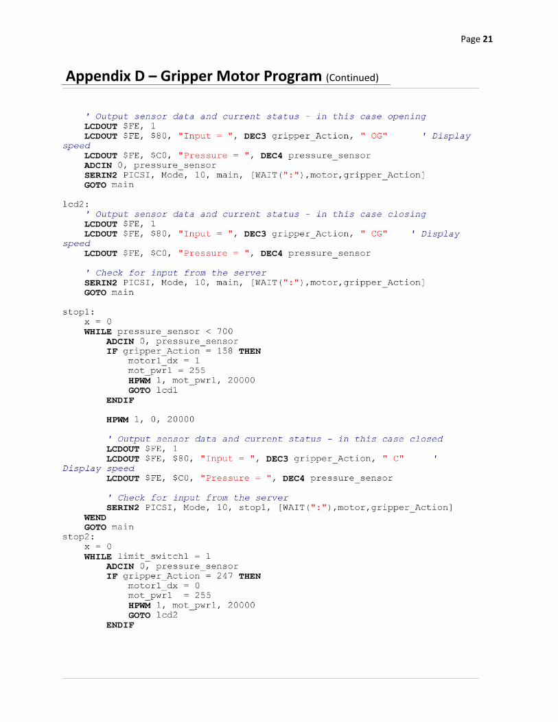
Page 21
Appendix D – Gripper Motor Program (Continued)
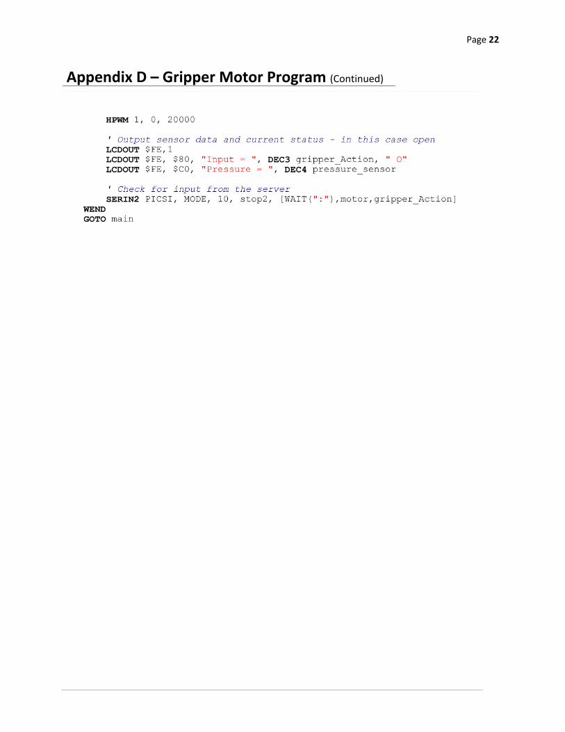
Page 22
Appendix D – Gripper Motor Program (Continued)
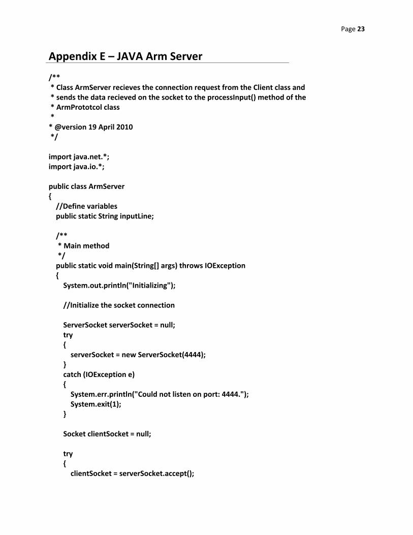
Page 23
Appendix E – JAVA Arm Server
/** * Class ArmServer recieves the connection request from the Client class and * sends the data recieved on the socket to the processInput() method of the * ArmPrototcol class * * @version 19 April 2010 */ import java.net.*; import java.io.*; public class ArmServer { //Define variables public static String inputLine; /** * Main method */ public static void main(String[] args) throws IOException { System.out.println("Initializing"); //Initialize the socket connection ServerSocket serverSocket = null; try { serverSocket = new ServerSocket(4444); } catch (IOException e) { System.err.println("Could not listen on port: 4444."); System.exit(1); } Socket clientSocket = null; try { clientSocket = serverSocket.accept();
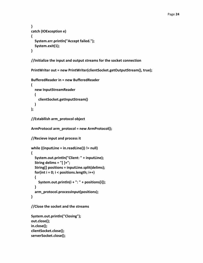
Page 24
} catch (IOException e) { System.err.println("Accept failed."); System.exit(1); } //Initialize the input and output streams for the socket connection PrintWriter out = new PrintWriter(clientSocket.getOutputStream(), true); BufferedReader in = new BufferedReader ( new InputStreamReader ( clientSocket.getInputStream() ) ); //Establlish arm_protocol object ArmProtocol arm_protocol = new ArmProtocol(); //Recieve input and process it while ((inputLine = in.readLine()) != null) { System.out.println("Client: " + inputLine); String delims = "[ ]+"; String[] positions = inputLine.split(delims); for(int i = 0; i < positions.length; i++) { System.out.println(i + ": " + positions[i]); } arm_protocol.processInput(positions); } //Close the socket and the streams System.out.println("Closing"); out.close(); in.close(); clientSocket.close(); serverSocket.close();

Page 25
} }
Page 26
Appendix F – JAVA Server Protocol
/** * Class ArmProtocol recieves the data from class ArmServer and * sends it through the RS232 serial COM ports to the microcontrollers * * @version 19 April 2010 */ import gnu.io.CommPort; import gnu.io.CommPortIdentifier; import gnu.io.SerialPort; import gnu.io.SerialPortEvent; import gnu.io.SerialPortEventListener; import java.io.*; import java.io.IOException; import java.io.InputStream; import java.io.OutputStream; import java.net.*; public class ArmProtocol { //instance variables int[] oldPositions; SerialPort serialPort1,serialPort2,serialPort3,serialPort4; InputStream in1, in2, in3, in4; OutputStream out1, out2, out3, out4; /** * Constructor for ArmProtocol objects */ ArmProtocol() { oldPositions = new int[4]; for(int position : oldPositions) { position = 0; } try {
Page 27
connect("COM1"); } catch(Exception e){} try { connect("COM2"); } catch(Exception e){} try { connect("COM7"); } catch(Exception e){} try { connect("COM8"); } catch(Exception e){} } /** * Method connect initializes the COM port identified in portName * * @param portName Port to be initialized * @return void */ void connect ( String portName) throws Exception { CommPortIdentifier portIdentifier = CommPortIdentifier.getPortIdentifier(portName); if ( portIdentifier.isCurrentlyOwned() ) { System.out.println("Error: Port is currently in use"); } else { if(portName.equalsIgnoreCase("COM1")) { CommPort commPort = portIdentifier.open("PIC1",2000); if ( commPort instanceof SerialPort ) { System.out.println("Setting up COM1"); serialPort1 = (SerialPort) commPort;
Page 28
serialPort1.setSerialPortParams(9600,SerialPort.DATABITS_8,SerialPort.STOPBITS_1,SerialPort.PARITY_NONE); in1 = serialPort1.getInputStream(); out1 = serialPort1.getOutputStream(); serialPort1.addEventListener(new SerialReader(in1)); serialPort1.notifyOnDataAvailable(true); } else { System.out.println("Error: Only serial ports are handled by this example."); } } if(portName.equals("COM2")) { CommPort commPort = portIdentifier.open("PIC2",2000); if ( commPort instanceof SerialPort ) { System.out.println("Setting up COM2"); serialPort2 = (SerialPort) commPort; serialPort2.setSerialPortParams(9600,SerialPort.DATABITS_8,SerialPort.STOPBITS_1,SerialPort.PARITY_NONE); in2 = serialPort2.getInputStream(); out2 = serialPort2.getOutputStream(); serialPort2.addEventListener(new SerialReader(in2)); serialPort2.notifyOnDataAvailable(true); } else { System.out.println("Error: Only serial ports are handled by this example."); } } if(portName.equals("COM7")) { CommPort commPort = portIdentifier.open("PIC3",2000); if ( commPort instanceof SerialPort ) { System.out.println("Setting up COM7"); serialPort3 = (SerialPort) commPort;
Page 29
serialPort3.setSerialPortParams(9600,SerialPort.DATABITS_8,SerialPort.STOPBITS_1,SerialPort.PARITY_NONE); in3 = serialPort3.getInputStream(); out3 = serialPort3.getOutputStream(); serialPort3.addEventListener(new SerialReader(in3)); serialPort3.notifyOnDataAvailable(true); } else { System.out.println("Error: Only serial ports are handled by this example."); } } if(portName.equals("COM8")) { CommPort commPort = portIdentifier.open("PIC4",2000); if ( commPort instanceof SerialPort ) { System.out.println("Setting up COM8"); serialPort4 = (SerialPort) commPort; serialPort4.setSerialPortParams(9600,SerialPort.DATABITS_8,SerialPort.STOPBITS_1,SerialPort.PARITY_NONE); in4 = serialPort4.getInputStream(); out4 = serialPort4.getOutputStream(); serialPort4.addEventListener(new SerialReader(in4)); serialPort4.notifyOnDataAvailable(true); } else { System.out.println("Error: Only serial ports are handled by this example."); } } } } /** * Class SerialReader recieves any input from the PIC microcontrollers. * It is currently unused as communication only is transmitted, not * recieved. */
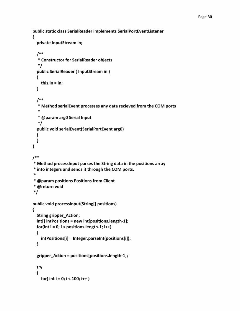
Page 30
public static class SerialReader implements SerialPortEventListener { private InputStream in; /** * Constructor for SerialReader objects */ public SerialReader ( InputStream in ) { this.in = in; } /** * Method serialEvent processes any data recieved from the COM ports * * @param arg0 Serial Input */ public void serialEvent(SerialPortEvent arg0) { } } /** * Method processInput parses the String data in the positions array * into integers and sends it through the COM ports. * * @param positions Positions from Client * @return void */ public void processInput(String[] positions) { String gripper_Action; int[] intPositions = new int[positions.length‐1]; for(int i = 0; i < positions.length‐1; i++) { intPositions[i] = Integer.parseInt(positions[i]); } gripper_Action = positions[positions.length‐1]; try { for( int i = 0; i < 100; i++ )
Page 31
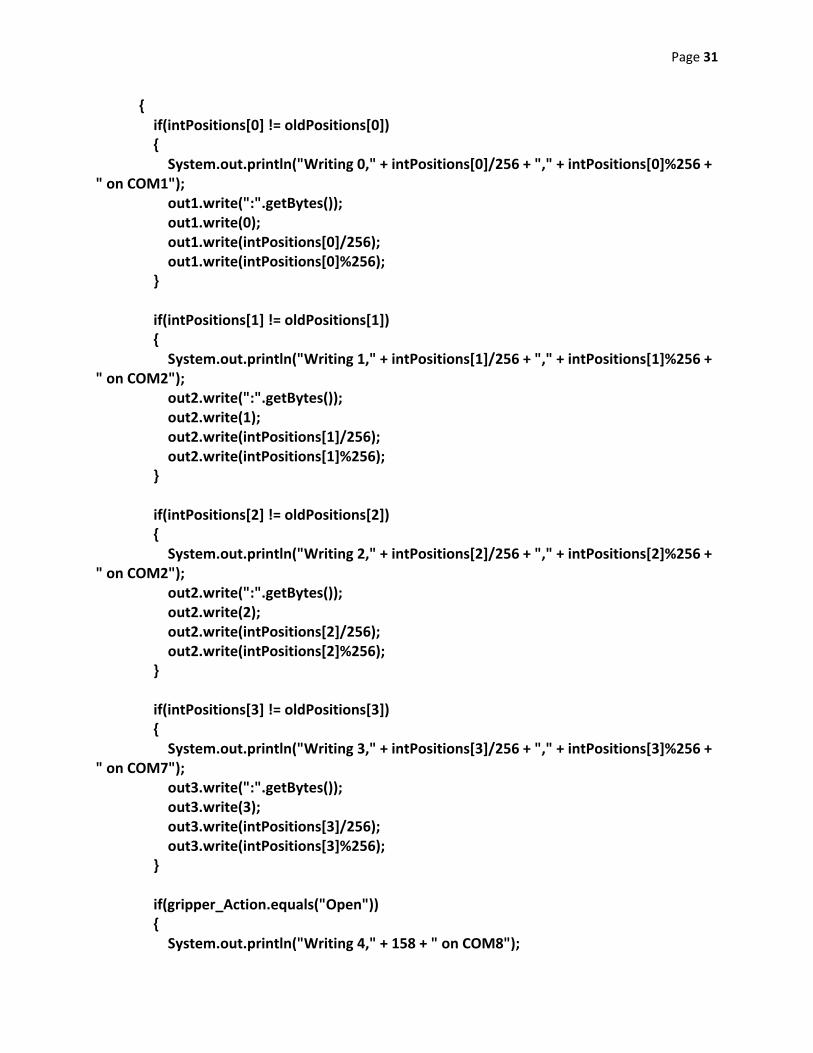
{ if(intPositions[0] != oldPositions[0]) { System.out.println("Writing 0," + intPositions[0]/256 + "," + intPositions[0]%256 + " on COM1"); out1.write(":".getBytes()); out1.write(0); out1.write(intPositions[0]/256); out1.write(intPositions[0]%256); } if(intPositions[1] != oldPositions[1]) { System.out.println("Writing 1," + intPositions[1]/256 + "," + intPositions[1]%256 + " on COM2"); out2.write(":".getBytes()); out2.write(1); out2.write(intPositions[1]/256); out2.write(intPositions[1]%256); } if(intPositions[2] != oldPositions[2]) { System.out.println("Writing 2," + intPositions[2]/256 + "," + intPositions[2]%256 + " on COM2"); out2.write(":".getBytes()); out2.write(2); out2.write(intPositions[2]/256); out2.write(intPositions[2]%256); } if(intPositions[3] != oldPositions[3]) { System.out.println("Writing 3," + intPositions[3]/256 + "," + intPositions[3]%256 + " on COM7"); out3.write(":".getBytes()); out3.write(3); out3.write(intPositions[3]/256); out3.write(intPositions[3]%256); } if(gripper_Action.equals("Open")) { System.out.println("Writing 4," + 158 + " on COM8");
Page 32
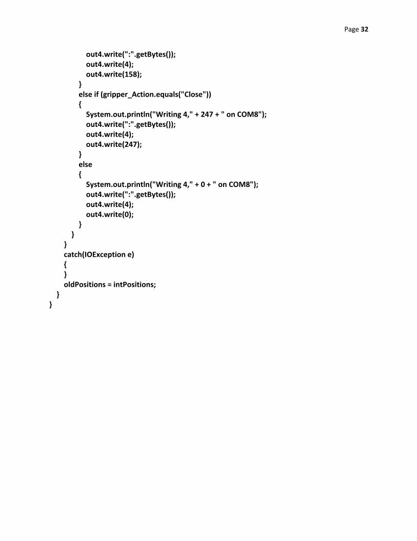
out4.write(":".getBytes()); out4.write(4); out4.write(158); } else if (gripper_Action.equals("Close")) { System.out.println("Writing 4," + 247 + " on COM8"); out4.write(":".getBytes()); out4.write(4); out4.write(247); } else { System.out.println("Writing 4," + 0 + " on COM8"); out4.write(":".getBytes()); out4.write(4); out4.write(0); } } } catch(IOException e) { } oldPositions = intPositions; } }
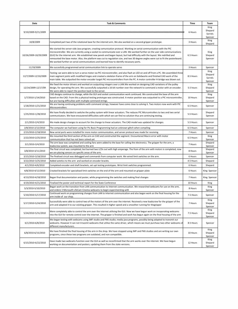
Date Task & Comments Time Team
9/10/2009‐9/21/2009 ############################################################################################################# 6 Hours
King
Shepard
Sorrels
Spencer
10/8/2009 Completed part two of the rotational base for the internet arm. We also worked on a second gripper prototype. 3 HoursKing
Shepard
10/26/2009‐10/29/2009
We started the server‐side Java program, creating comunication protocol. Working on serial communication with the PIC
microcontroller. We are currently using a socket to communicate over a LAN. We worked further on the user side communications
(GUI) for the internet arm. We established new panels and began layout, but had difficulty with the layout. We redrilled and
remounted the base motor. Also, the platform was cut to regulation size, and two 30 degree angles were cut to fit the posterboard.
We worked further on serial communications and learned how to identify necassary ports.
6.5 Hours
King
Shepard
Spencer
11/19/2009 We succesfully programmed serial communication link to operate servo 3 Hours Spencer
12/7/2009‐12/10/2009
Testing: we were able to turn a servo motor via PIC microcontroller, and also flash an LED on and off from a PC. We assembled three
main segment joints with modified hinges and created a skeleton frame of the arm on Solidworks and finished CAD work of the
main table. We outputted the motor encoder target PIC microcontrollers from the PC. A motor controller H‐bridge was blown out.
8.5 Hours
King
Shepard
Sorrels
Spencer
12/14/2009‐12/17/09
We fixed the motor drivers and worked on outputting integers over a LAN.We worked on designing CAD variations of the pulley
design, for operating the arm. We successfully outputted a 16‐bit number over the network to command a motor with an encoder.
We were able to report the position back to the server.
5.5 hours
King
Shepard
Spencer
1/7/2010‐1/14/2010
CAD designs continue to change, while the GUI and socket communication work continued. We constructed the base of the arm
based on the CAD. From this a physical testing prototype was constructed. A motor position was outputted to a PIC microcontroller,
but are having difficulties with multiple command strings.
10 Hours
King
Shepard
Spencer
1/18/2010‐1/21/2010We are having continuing problems with command strings, however have come close to solving it. Two motors now work with PIC
Microcontrollers6.5 Hours Spencer
1/25/2010‐1/28/2010We have finally decided to switche the pulley system with linear actuators. The reduces PIC Micrcontrollers to two and two serial
communicators. We have encoutered difficulties with which we can find no solution thus are continuing testing.5.5 Hours
Shepard
Spencer
2/1/2010‐2/4/2010 We made design changes to account for the change to linear actuators. The CAD model was updated for changes. 5.5 Hours Spencer
2/8/2010‐2/12/2010 The computer we had been using for Pic Basic Programming had an unknown glitch when compiling. 6.5 Hours Spencer
2/15/2010‐2/18/2010 New serial ports were installed for more motor communication, and server protocol was made for receiving 7 Hours Spencer
2/22/2010‐2/25/2010We mounted the third section of the arm on CAD and constructed the segment. Encountered Macro error with motor
communication that has not been solved yet6.5 Hours
King
Spencer
3/1/2010‐3/4/2010The arm base was completed and cooling fans were added to the base for colling the electronics. The gripper for the arm, a
leadscrew system, was mounted to the arm7 Hours
Shepard
Spencer
3/8/2010‐3/11/2010The final circuit was completed, but burned two LCDs out with high amperage. The fram of the arm with motors is completed, now
we are placing sensors on specific areas of the arm.8 Hours
Shepard
Spencer
3/15/2010‐3/18/2010 The finalised circuit was debugged and commands from computer work. We wired limit switches on the arm. 6 Hours Spencer
3/22/2010‐3/25/2010 Added astetics to the arm and worked on encoder brackts. 4.5 Hours Shepard
4/1/2010‐4/6/2010 Completed encoder and shaft brackets, set upt testing prototypes. Wrist limit switches programmed. 6 Hours Shepard
4/8/2010‐4/12/2010 Created brackets for specialised limit switches on the end of the arm and mounted on gripper plate 6 Hours King Spencer
4/13/2010‐4/18/2010 Began final documentation and poster, while programming the switches and making final changes 7 Hours King Spencer
4/19/2010‐4/21/2010 Finalised the poster and technical report for the State Conference 10 Hours King
5/3/2010‐5/10/2010Began work on the transition from LAN communication to Internet communication. We researched webcams for use on the arm,
and ordere 3 Microsoft LifeCam Cinema webcams to begin experimenting with8 Hours
King
Spencer
5/10/2010‐5/17/2010Continued work on programming changes from LAN to Internet communication and also began work on the final housing for the
arm inside of our shop. 7.5 Hours Spencer
5/17/2010‐5/24/2010Successfully were able to control two of the motors of the arm over the internet. Received a new leadscrew for the gripper of the
arm and adapted it to our existing gripper. This resulted in higher speed and a smoother running for thegripper7 Hours
King
Shepard
Spencer
5/24/2010‐5/31/2010Were completely able to control the arm over the internet utilising the GUI. Now we have begun work on incoporating webcams
into the GUI for remote control over the internet. The gripper is finished and work has begun again on the final housing of the arm7.5 Hours
King
Shepard
Spencer
6/1/2010‐6/8/2010
We began testing with webcams using JMF studio and FMJ studio; media java programs, possibly being adapted to transmit our
webcams. However it can not trnasmit webcams that utilise the same driver, which means we must purchase two other webcams of
different manufacturers.
8.5 Hours Spencer
6/8/2010‐6/15/2010We have finished the final housing of the arm in the shop. We have stopped using JMF and FMJ studios and are writing our own
programs, since these two programs are outdated, and non compatible.10 Hours
King
Shepard
Spencer
6/15/2010‐6/22/2010Have made two webcams function over the GUI as well as reconfirmed that the arm works over the internet. We have begun
working on documentation and posters; updating them from the state versions.12 Hours
King
Shepard
Spencer