Embed Size (px)
Citation preview
THERMO ELECTRON CORPORATION
ELECTROPORATION
OPTIMISATION GUIDE
Thermo Electron Corporation Bioscience Technologies Division USA and rest of world: (001) 866 984 3766 UK and Europe: +44 (0) 1256 817282 Internet: www.thermo.com/molecularbiology Email: [email protected]
STOCK CODE: EPES006
FS31999
© Thermo Electron Corporation 2003 Issue 4.0, June 2003 i i
International Sales, Service & Technical Support
UK and Europe: +44 (0) 1256 817282
USA and rest of the world +1 866 984 3766
WARNING
• Products offered by Thermo are exclusively intended for research and to be
used by Scientists familiar with the potential hazards. • This document aims at giving advice for operation and does not involve any
responsibility for Thermo. • Thermo reserves the right to modify its products at any time and without prior
notice.
© Thermo Electron Corporation 2003 Issue 4.0, June 2003 i i i
THERMO ELECTRON ELECTROPORATION OPTIMISATION GUIDE
TABLE OF CONTENTS
Page CHAPTER I: INTRODUCTION 7
CHAPTER II: ELECTROPORATION-MOST IMPORTANT PARAMETERS 3
Electrical Factors 3
Other Parameters 3
CHAPTER III: BACTERIAL ELECTROPORATION 5
Introduction 5 How to Prepare Bacteria for Electroporation 5
Electroporation of E.Coli 6 Output Voltage and Electric Field Using 1&2mm Cuvettes 7 Optimization Advice for Gram-Bacteria 7
Optimization Advice for Gram+Bacteria 7 General Optimization Advice for Bacteria 8 Troubleshooting ~ Bacterial Electroporation 8
CHAPTER IV: MAMMALIAN CELL ELECTROPORATION 11
Introduction 11 Cell Harvesting 11 Standard Cell Line Electroporation 12
Optimization Advice for Mammalian Cell Lines 13 Optimization Advice for Primary Mammalian Cells 13 General Optimization Advice for Mammalian Cells 14
Troubleshooting ~ Mammalian Cell Electroporation 15
CHAPTER V: YEAST ELECTROPORATION 19
Yeast Preparation for Electroporation 17 Electroporation 17
Optimization Advice for Yeast 18 General Optimization Advice for Yeast 18 Troubleshooting ~ Yeast Electroporation 19
CHAPTER VI: SPECIAL APPLICATIONS 21
Fish, birds and other eukaryotic cell electroporation 21 Standard parameters for using the optipulse option 21 Tissue electroporation using 10mm cuvettes 22
CHAPTER VII: INTACT PLANT ELECTROPORATION 23
© Thermo Electron Corporation 2003 Issue 4.0, June 2003 iv
Plant Preparation 23
Plant Bud Electroporation 24 General Optimization Advice for Intact Plant 24
CHAPTER VIII: PLANT PROTOPLAST ELECTROPORATION 27
Plant Protoplast Preparation 27
Plant Protoplast Electroporation 27 General Optimization Advice For Plant Protoplast 27
CHAPTER IX: PROTEIN, OLIGO AND SMALL MOLECULE ELECTROPORATION29
CHAPTER X: DNA PURIFICATION 31
Introduction 31
Purification of Closed Circular DNA 31 Removal of RNA From Preparation of Plasmid DNA 32 Desalting of Ligation Mix 33
CHAPTER XI: DOUBLE & OPTIPULSE 35
DoublePulse® Electroporation 35 Energy Level Single Pulse versus DoublePulse 35 OptiPulse™ 36
CHAPTER XII: MEDIUM AND BUFFERS 38
LB Medium (Luria-Bertani Medium) 36 SOB Medium 36 SOC Medium 36
2x HEPES-Buffered Saline 37 Phosphate-Buffered Saline (PBS) 37 1M Tris 37
TE 37 STE (Also Called TEN) 37 STET 38
TNT 38
CHAPTER XIII: GENERAL INFORMATION 40
The Cleanliness of the Glassware and Plasticware. 40 Transfection Principle 40
Transient Transfection 40 Stable Transfection 40 Primary Cells and Cell Lines 40
Primary Cell Culture 40 Finite Cell Line 41 Established Cell Line 41
Adherent and Suspension Cells 41 Adherent Cells 41 Suspension Cells 41
Media and Supplements 41 Serum 41 Transfection Methods 41
Plasmid DNA Quality 42 Conformation and Concentration of DNA 42 Genetic Reporter Systems 42
Commonly Used Reporter Genes 42
© Thermo Electron Corporation 2003 Issue 4.0, June 2003 v
Chloramphenicol Acetyltransferase 42 Firefly Luciferase 42 B-Galactosidase 43 Human Growth Hormone (HGH) 43 Green Fluorescent Protein 43
CHAPTER XIV: ELECTRICAL BASICS 43
Electric Field 43 Capacitor 44
Pulse Energy 44 Pulse Time 44 Basic Designs for Low Voltage Application 45
Total Resistance and Pulse Time 46 Basic Design for High Voltage Application 46
CHAPTER XV: ORDERING INFORMATION 40

© Thermo Electron Corporation 2003 Issue 4.0, June 2003 vi
© Thermo Electron Corporation 2003 Issue 4.0, June 2003 vii
THERMO ELECTRON ELECTROPORATION
OPTIMISATION GUIDE
CHAPTER I: INTRODUCTION
During electroporation a trans-membrane electric field is induced by an external electric field, usually a short Direct Current (DC) pulse being applied to the cell suspension. This trans-membrane electric field induces local destabilisationi of the cell membrane, commonly called electropores ii. During the destabilisation period, the membrane is highly permeable to small molecules iii like ions and water, but also to macromolecules as large as DNA iv. If suitable electrical pulse parameters are used, the cells will recover, the electropores reseal spontaneously and continued growth is ensured. The actual mechanism is still not fully understood, other than the thermal motion for small molecules. For the macromolecule transport, it is known that the polarity is important and involved in the electrophoretic movement of the DNAv,vi into the cell.

© Thermo Electron Corporation 2003 Issue 4.0, June 2003 2
© Thermo Electron Corporation 2003 Issue 4.0, June 2003 3
THERMO ELECTRON ELECTROPORATION
OPTIMISATION GUIDE
CHAPTER II: ELECTROPORATION-MOST IMPORTANT PARAMETERS
Electrical Factors
Cell permeability induced by electroporation is dependent on the following parameters: The electric field (E) and pulse duration (τ) depends on the reciprocal of cell diameter (see chapter 13 for electrical background). The electric field to get efficient electroporation varies from 450V.cm-1 for large insect cell to 12.5 kV.cm-1 and higher for bacteria. The electric field and pulse duration has to be above the lower working limitvii. Pore number and pore diameter increase with the product of the electric field and pulse duration. However, if the upper working limit is reached this causes the cell to be irreversibly damaged. Other Parameters
Results will also depend on the following parameters: The purity of the molecule to be transferred. Impurities that will be transferred into the cells during electroporation have potential unpredictable side effects, and generally will increase cell mortality. In chapter 10 we describe techniques for DNA purification. The purity of water and other chemicals in contact with the cells during the electroporation process is also critical for the same reasons described here as above. Freshly prepared 18~MOhms water (MilliQ®) should be used whenever it is possible. The chemicals used for the preparation of the samples should be of molecular biology grade and usage should be restricted to electroporation only. The cleanness of the vessel in contact with sample is also very important. Detergents are known to dramatically decrease transformation efficiency. Disposable vessels should be used wherever it is possible. In any case, vessels contaminated with detergents should be avoided for the preparation of the samples and to store these chemicals, including water. The quality of the electroporation cuvette used is extremely important. Top quality cuvettes should be used for critical experiments. Reusing the cuvette is common but the transformation efficiency will decrease over a period of time because the oxidation of the aluminium will change the electroporation conditions by adding an extra serial resistance into the circuit. Steam1 sterilisation speed-up the oxidation process and should be avoided. Reusing
1 Some cuvette manufacturers suggest this type of sterilisation. We strongly recommend not to use this method!
© Thermo Electron Corporation 2003 Issue 4.0, June 2003 4
the cuvette increases the risk of contamination and more seriously increases the risk to transfer a wrong DNA. Post electroporation events. Due to the electrolysis of the electroporation buffer, after the pulse the cells are in a very hostile environment and must be diluted and transferred as quickly as possible (less than 30 seconds) in the appropriate outgrowth medium. Cell preparation and growth phase. Cell preparation is very important. Fast growing cells are usually considered better for electroporation2.
2 However it is now possible to electroporate efficiently quiescent cells with the InSitu electroporation system from Thermo
© Thermo Electron Corporation 2003 Issue 4.0, June 2003 5
THERMO ELECTRON ELECTROPORATION
OPTIMISATION GUIDE
CHAPTER III: BACTERIAL ELECTROPORATION
Introduction
The conditions for electroporation efficiency vary between different cell types. However, for most of the bacteria the optimum electric field is 12,5kV.cm-1 or 18,0kV.cm-1, and the optimum pulse time is 5ms. Usually you will use an output voltage of 2.5kV with the 2mm cuvettes and 1.8kV with the 1mm cuvettes.
How to Prepare Bacteria for Electroporation
This is an optimised protocol for E.Coli. Please adapt it according to the bacteria strain used. 1. Prepare a 10ml pre-culture on LB medium. For best results, avoid
using over-night pre-culture. 2. Dilute pre-culture as follows: 4 ml in 200-ml of fresh LB pre-
warmed at 37°C. 3. Grow the cells at 37°C. 4. When OD(600)=0.6 is reached, chill the culture on ice as quickly
as possible. 5. Centrifuge in disposable tubes (50ml disposable type) for 5
minutes at 3000 rpm. 6. Re-suspend the pellets in 25ml freshly prepared water3 (MilliQ®
quality) at ice temp. 7. Repeat steps 5 & 6 twice more. 8. Re-suspend the pooled pellets in 400µl (cell concentration should
be 1 x 10¹⁰ cells x ml-1) freshly prepared water (MilliQ® quality) at ice temp.
9. Check the final volume and add 10% of glycerol (molecular biology grade).
10. Use immediately or aliquot the electrocompetent cells to 100µl in 10% glycerol and freeze at minus 70°.
The following advice is valid for any kind of bacteria cells: Fast growing cells usually give better results Temperature decrease after stopping the cell growth must be as fast as possible. Carry out all post growing steps rapidly. Water quality is vital; we recommend you only use freshly prepared 18MΩ, stored in detergent free clean vessels, or ideally in a disposable vessel. 3 Never store this type of water in vessels, which have been washed with detergent. Disposable vessels are strongly recommended for best result.
© Thermo Electron Corporation 2003 Issue 4.0, June 2003 6
All chemicals used should be dedicated to electrocompetent cell preparation and of a molecular biology g rade.
Electroporation of E.Coli
1. Defrost an aliquot of electrocompetent cells. 2. Load an Eppendorf tube chilled on ice with 40µl4 of cell
suspension. 3. Add 1 to 5µl of ligation mix (DNA). 4. Mix well and keep on ice for 1 minute. 5. Select 2500 Volt as the output voltage. 6. Load a 2mm cuvette chilled on ice with the cell suspension.
Avoid putting your finger on the aluminium electrodes or it will dramatically increase the temperature of the sample and increase the risk of arcing.
7. Trigger the pulse immediately.
Cuvette 2mm Voltage 2500 Volts Capacitor 25µF5 Shunt Resistor 201R
8. As soon as possible (less than 30 seconds) re-suspend the cells
in the cuvette with 1ml SOC medium (the quality of the SOC is important).
9. Transfer the cells in an appropriate vessel and incubate at 37°C for 1 hour.
10. Plate the cells on the selective medium. 11. After approximately 24 hours read the results. The following advice is valid for all bacteria cells: Prior to electroporation samples and cuvettes must be stored on ice. Transfer the cuvette loaded with the samples shortly before you trigger the pulse. Avoid putting your finger on the aluminium electrodes or it will dramatically increase the temperature of the sample and increase the risk of arcing. As soon as possible (less than 30 seconds) re-suspend the cells in the cuvette with 1ml of outgrowth medium. Some ligation mix will need a desalting procedure prior to use (see chapter 10.4).
4 If you are using Thermo electroporation cuvettes you will be able to reduce the volume to 20µl with the 2mm model (Cat.# ECU-102) and to 10µl with the 1mm model (Cat.# ECU-101). These extremely low volumes are possible because of the special V-shape design of Thermo cuvette. If you are using commercial electrocompetent cells you will achieve significant economy.
5 25µF and 200R is the most common combination of capacitor and resistor to get the 5ms optimal pulse time. Some equipment are offering other combination resulting in 5ms pulse (EasyjecT Prima and Optima 15µF and 335R, Biorad MicroPulser® 10µF and 500R, EC-630 from BTX 40µF and +/- 130R
© Thermo Electron Corporation 2003 Issue 4.0, June 2003 7
Output Voltage and Electric Field Using 1&2mm Cuvettes
Output Voltage Cuvette Used Electric Field 1 800 Volts 1mm 18 000 V.cm-1
2 500 Volts 1mm 25 000 V.cm-1 1 800 Volts 2mm 9 000 V.cm-1 2 500 Volts 2mm 12 500 V.cm-1
Optimisation Advice for Gram-Bacteria
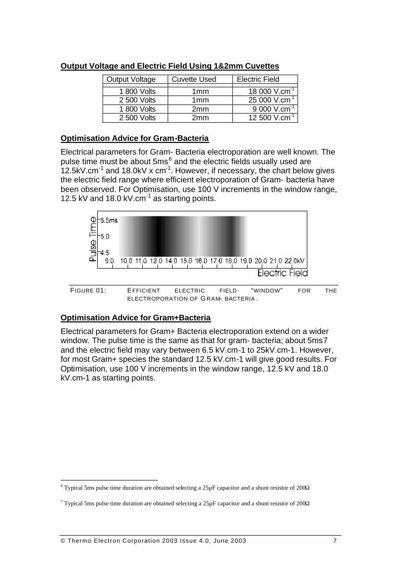
Electrical parameters for Gram- Bacteria electroporation are well known. The pulse time must be about 5ms6 and the electric fields usually used are 12.5kV.cm-1 and 18.0kV x cm-1. However, if necessary, the chart below gives the electric field range where efficient electroporation of Gram- bacteria have been observed. For Optimisation, use 100 V increments in the window range, 12.5 kV and 18.0 kV.cm-1 as starting points.
F IGURE 01: EFFICIENT ELECTRIC FIELD “WINDOW” FOR THE ELECTROPORATION OF G RAM- BACTERIA .
Optimisation Advice for Gram+Bacteria
Electrical parameters for Gram+ Bacteria electroporation extend on a wider window. The pulse time is the same as that for gram- bacteria; about 5ms7 and the electric field may vary between 6.5 kV.cm-1 to 25kV.cm-1. However, for most Gram+ species the standard 12.5 kV.cm-1 will give good results. For Optimisation, use 100 V increments in the window range, 12.5 kV and 18.0 kV.cm-1 as starting points.
6 Typical 5ms pulse time duration are obtained selecting a 25µF capacitor and a shunt resistor of 200Ω
7 Typical 5ms pulse time duration are obtained selecting a 25µF capacitor and a shunt resistor of 200Ω
© Thermo Electron Corporation 2003 Issue 4.0, June 2003 8
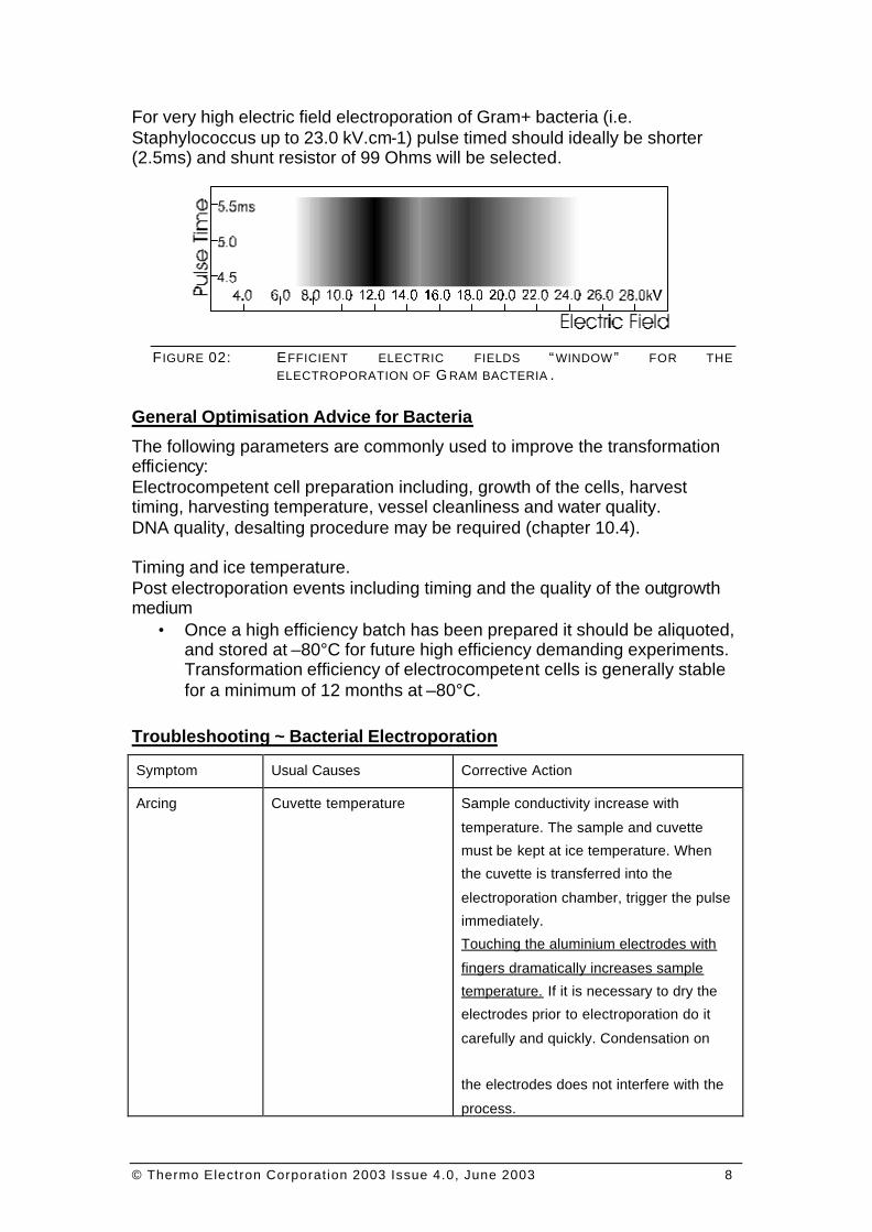
For very high electric field electroporation of Gram+ bacteria (i.e. Staphylococcus up to 23.0 kV.cm-1) pulse timed should ideally be shorter (2.5ms) and shunt resistor of 99 Ohms will be selected.
F IGURE 02: EFFICIENT ELECTRIC FIELDS “ WINDOW ” FOR THE ELECTROPORATION OF G RAM BACTERIA .
General Optimisation Advice for Bacteria
The following parameters are commonly used to improve the transformation efficiency: Electrocompetent cell preparation including, growth of the cells, harvest timing, harvesting temperature, vessel cleanliness and water quality. DNA quality, desalting procedure may be required (chapter 10.4). Timing and ice temperature. Post electroporation events including timing and the quality of the outgrowth medium
• Once a high efficiency batch has been prepared it should be aliquoted, and stored at –80°C for future high efficiency demanding experiments. Transformation efficiency of electrocompetent cells is generally stable for a minimum of 12 months at –80°C.
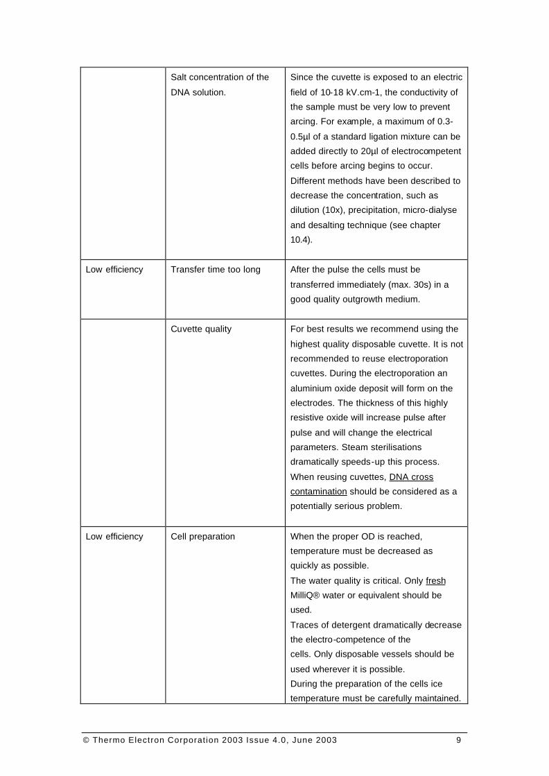
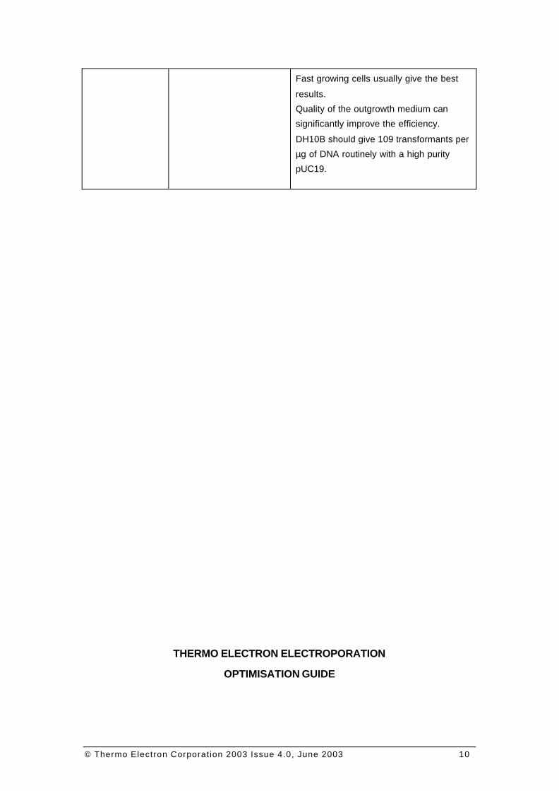
Troubleshooting ~ Bacterial Electroporation
Symptom Usual Causes Corrective Action
Arcing Cuvette temperature Sample conductivity increase with
temperature. The sample and cuvette
must be kept at ice temperature. When
the cuvette is transferred into the
electroporation chamber, trigger the pulse
immediately.
Touching the aluminium electrodes with
fingers dramatically increases sample
temperature. If it is necessary to dry the
electrodes prior to electroporation do it
carefully and quickly. Condensation on
the electrodes does not interfere with the
process.
© Thermo Electron Corporation 2003 Issue 4.0, June 2003 9
Salt concentration of the
DNA solution.
Since the cuvette is exposed to an electric
field of 10-18 kV.cm-1, the conductivity of
the sample must be very low to prevent
arcing. For example, a maximum of 0.3-
0.5µl of a standard ligation mixture can be
added directly to 20µl of electrocompetent
cells before arcing begins to occur.
Different methods have been described to
decrease the concentration, such as
dilution (10x), precipitation, micro-dialyse
and desalting technique (see chapter
10.4).
Low efficiency Transfer time too long After the pulse the cells must be
transferred immediately (max. 30s) in a
good quality outgrowth medium.
Cuvette quality For best results we recommend using the
highest quality disposable cuvette. It is not
recommended to reuse electroporation
cuvettes. During the electroporation an
aluminium oxide deposit will form on the
electrodes. The thickness of this highly
resistive oxide will increase pulse after
pulse and will change the electrical
parameters. Steam sterilisations
dramatically speeds-up this process.
When reusing cuvettes, DNA cross
contamination should be considered as a
potentially serious problem.
Low efficiency Cell preparation When the proper OD is reached,
temperature must be decreased as
quickly as possible.
The water quality is critical. Only fresh
MilliQ® water or equivalent should be
used.
Traces of detergent dramatically decrease
the electro-competence of the
cells. Only disposable vessels should be
used wherever it is possible.
During the preparation of the cells ice
temperature must be carefully maintained.
© Thermo Electron Corporation 2003 Issue 4.0, June 2003 10
Fast growing cells usually give the best
results.
Quality of the outgrowth medium can
significantly improve the efficiency.
DH10B should give 109 transformants per
µg of DNA routinely with a high purity
pUC19.
THERMO ELECTRON ELECTROPORATION
OPTIMISATION GUIDE
© Thermo Electron Corporation 2003 Issue 4.0, June 2003 11
CHAPTER IV: MAMMALIAN CELL ELECTROPORATION
Introduction
The conditions for electroporation efficiency vary between cell types. However, for most of the mammalian cells lines 8 the optimum electric field is 650 V.cm-1 with a pulse time of a few tens of milli-secondsviii. Usually you will use an output voltage of 250 V and a capacitor value of 1500µF with the 4mm cuvette loaded with 800µl of cell suspension.
Cell Harvesting
It is highly recommended to use the normal harvesting procedure. Any change could affect the cell capability to survive the electroporation treatment.
1. Harvest the cells as normal using the standard laboratory procedure. Do not attempt for example to reduce the trypsin concentration or exposure time.
2. Wash the cells twice in growth medium by pelleting (50g for 10 minutes) to remove contaminating trypsin.
3. Re-suspend them in 50ml of growing medium at room temperature.
4. Carefully count the cells. The concentration of the cells in the electroporation medium should be carefully controlled to obtain reproducible transfection efficiencies.
5. Pellets aliquots of 5.106cells in 1.5ml Eppendorf tubes at 50g for 10 minutes.
6. For each sample, mix in a 1.5ml Eppendorf tube9, 30µg of purified DNA10 (only for the first trials, adjust the DNA concentration), and adjust the final volume to 800µl with growing medium or even better with OptiBuffer (Cat # EKIT-E1).
7. Re-suspend the cells in the electroporation medium and incubate at room temperature for 1 to 3 minutes maximum.
8 Primary cells usually require higher electric field i.e. 750.cm-1
9 You can prepare the sample into the cuvette but is more difficult to mix.
10 See DNA purification section in this book, Chapter X.
© Thermo Electron Corporation 2003 Issue 4.0, June 2003 12
The following advice is valid for any kind of mammalian cells: Fast growing cells usually give better results. For cells growing adherent11, we recommend to harvest at 50% to 70% confluence. Operations following trypsinisation must be done in the shortest time possible. Trypsinisation removes some of the membrane embedded proteins, increasing membrane fluidity and easing pores resealing after the pulse, thus usually increasing cell survival after electroporation. Water quality is important; we recommend you only use freshly prepared 18MΩ, stored in detergent free clean vessels, or better in a disposable vessel. All chemicals used should be dedicated to cell culture and preparation and should be a molecular biology grade. Standard Cell Line Electroporation
1. Transfer the cell suspension into the cuvette at room temperature. 2. Trigger the pulse immediately.
Cuvette 4mm Voltage 250 Volts Capacitor 1500µF Shunt Resistor …… (Infinite)
3. Immediately (less then 30 seconds is recommended after the
pulse) transfer the cell suspension to a dish containing pre-warmed culture medium with serum.
The following advice is valid for all mammalian cells: DNA quality is critical. We recommend CsCl centrifugation followed by the NaCl centrifugation. However, good quality endotoxin free purification kits can be a suitable alternative (see chapter 10.2 and 10.3). DNA concentration required can be relatively high. When DNA is purified as recommended the electroporation efficiency increases linearly with the DNA concentration. Mammalian cell electroporation should be done at room temperature, which increases membrane fluidity and eases pore resealing after the pulse, thus usually increasing cell survival. The electroporation medium can be critical for successful electroporation. We recommend using the normal growing medium with or without serum. Thermo
11 However it is now possible to electroporate efficiently quiescent cells with the InSitu electroporation system from Thermo
© Thermo Electron Corporation 2003 Issue 4.0, June 2003 13
OptiBuffer, which mimics cytoplasm composition, may also greatly improve12 electroporation efficiency. After the electrical pulse it is critical to transfer the cells in fresh medium within seconds. During the pulse electrolyses will dramatically change the buffer composition. The medium will change in a very hostile environment for the treated cells and could result in a dramatic decrease of the experiment efficiency. Never incubate cells in the cuvette after the pulse. Optimisation Advice for Mammalian Cell Lines
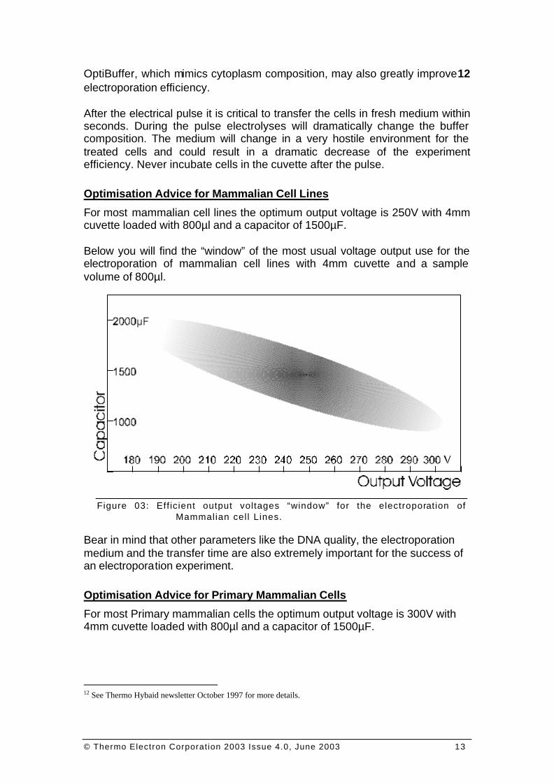
For most mammalian cell lines the optimum output voltage is 250V with 4mm cuvette loaded with 800µl and a capacitor of 1500µF. Below you will find the “window” of the most usual voltage output use for the electroporation of mammalian cell lines with 4mm cuvette and a sample volume of 800µl.
Figure 03: Eff icient output voltages “window” for the electroporation of Mammalian cel l Lines.
Bear in mind that other parameters like the DNA quality, the electroporation medium and the transfer time are also extremely important for the success of an electroporation experiment. Optimisation Advice for Primary Mammalian Cells
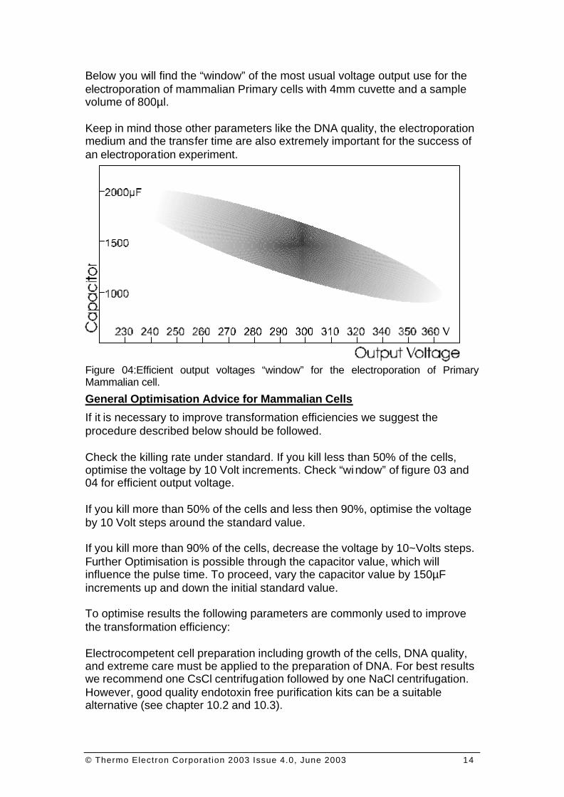
For most Primary mammalian cells the optimum output voltage is 300V with 4mm cuvette loaded with 800µl and a capacitor of 1500µF.
12 See Thermo Hybaid newsletter October 1997 for more details.
© Thermo Electron Corporation 2003 Issue 4.0, June 2003 14
Below you will find the “window” of the most usual voltage output use for the electroporation of mammalian Primary cells with 4mm cuvette and a sample volume of 800µl. Keep in mind those other parameters like the DNA quality, the electroporation medium and the transfer time are also extremely important for the success of an electroporation experiment. Figure 04:Efficient output voltages “window” for the electroporation of Primary Mammalian cell.
General Optimisation Advice for Mammalian Cells
If it is necessary to improve transformation efficiencies we suggest the procedure described below should be followed. Check the killing rate under standard. If you kill less than 50% of the cells, optimise the voltage by 10 Volt increments. Check “window” of figure 03 and 04 for efficient output voltage. If you kill more than 50% of the cells and less then 90%, optimise the voltage by 10 Volt steps around the standard value. If you kill more than 90% of the cells, decrease the voltage by 10~Volts steps. Further Optimisation is possible through the capacitor value, which will influence the pulse time. To proceed, vary the capacitor value by 150µF increments up and down the initial standard value. To optimise results the following parameters are commonly used to improve the transformation efficiency: Electrocompetent cell preparation including growth of the cells, DNA quality, and extreme care must be applied to the preparation of DNA. For best results we recommend one CsCl centrifugation followed by one NaCl centrifugation. However, good quality endotoxin free purification kits can be a suitable alternative (see chapter 10.2 and 10.3).
© Thermo Electron Corporation 2003 Issue 4.0, June 2003 15
Electroporation medium quality is also very important. During the process the cells will be highly exposed to the external medium. It is recommended to use your usual growth medium supplemented as necessary with serum or even better, OptiBuffer. Post electroporation events including timing and the quality of the outgrowth medium
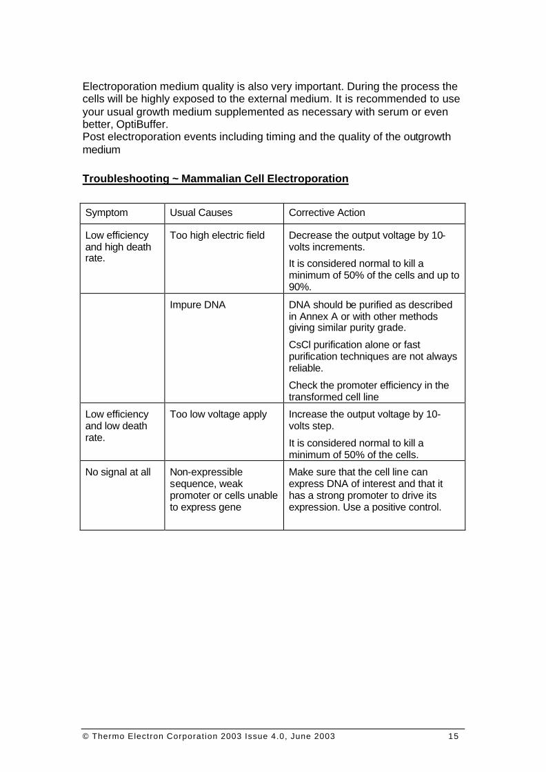
Troubleshooting ~ Mammalian Cell Electroporation
Symptom Usual Causes Corrective Action
Low efficiency and high death rate.
Too high electric field Decrease the output voltage by 10-volts increments.
It is considered normal to kill a minimum of 50% of the cells and up to 90%.
Impure DNA DNA should be purified as described in Annex A or with other methods giving similar purity grade.
CsCl purification alone or fast purification techniques are not always reliable.
Check the promoter efficiency in the transformed cell line
Low efficiency and low death rate.
Too low voltage apply Increase the output voltage by 10-volts step.
It is considered normal to kill a minimum of 50% of the cells.
No signal at all Non-expressible sequence, weak promoter or cells unable to express gene
Make sure that the cell line can express DNA of interest and that it has a strong promoter to drive its expression. Use a positive control.

© Thermo Electron Corporation 2003 Issue 4.0, June 2003 16
THERMO ELECTRON ELECTROPORATION
© Thermo Electron Corporation 2003 Issue 4.0, June 2003 17
OPTIMISATION GUIDE
CHAPTER V: YEAST ELECTROPORATION
The protocol has been optimised for Saccharomyces cerevisae is valid for most yeast strains. However, growth conditions, growing medium, outgrowth medium and selection methods will need to be adapted.
Yeast Preparation for Electroporation
1. Inoculate 500ml YPD broth in a 2 – 1 flask. Grow with vigorous shaking at 30°C to OD600mm = 1.3 -1.5 (approximately 1 x 10¹⁰ cells/ml).
2. Harvest the culture by centrifugation and resuspend in 100ml YPD broth. Add 2.0ml sterile 1M HEPES, pH 8.0 (20mM final concentration) and then add 2.5ml sterile 1M dithiothreitol (DTT; 25mM final concentration) while swirling gently. Incubate 15 min at 30°C with gentle shaking.
3. Bring to 500ml with Milli-Q H2O. 4. Concentrate the cells approximately 1000-fold with several
centrifugations, re-suspending the successive pellets as follows: 1st pellet: 500ml Milli-Q H2O 2nd pellet: 250ml Milli-Q H2O 3rd pellet: 20ml 1M sorbitol 4th pellet: 0.5ml 1M sorbitol Resuspension should be vigorous. The rotor, the speed and exact duration of centrifuge spins are not critical. All solutions should be ice-cold. Final volume of resuspended yeast should be about 1.0 -1.5ml.
5. Re-suspend the cells in an appropriate volume of washing solution so as to reach an OD600 of 400. This means that the final volume should be 1/400 to 1/200 of the initial culture volume. The cells can be kept on ice for several hours without any loss of transformation frequency.
Electroporation
1. In a cold 1.5ml Eppendorf tube mix together the DNA (optimum amount of DNA is 100ng) and 40µl of yeast suspension. Keep on ice for 3 minutes.
2. Transfer the DNA/Yeast mixture in a cold 2mm-electroporation cuvette. The quality of the DNA influences strongly the transformation frequency. Incubate on ice for 5 minutes.
© Thermo Electron Corporation 2003 Issue 4.0, June 2003 18
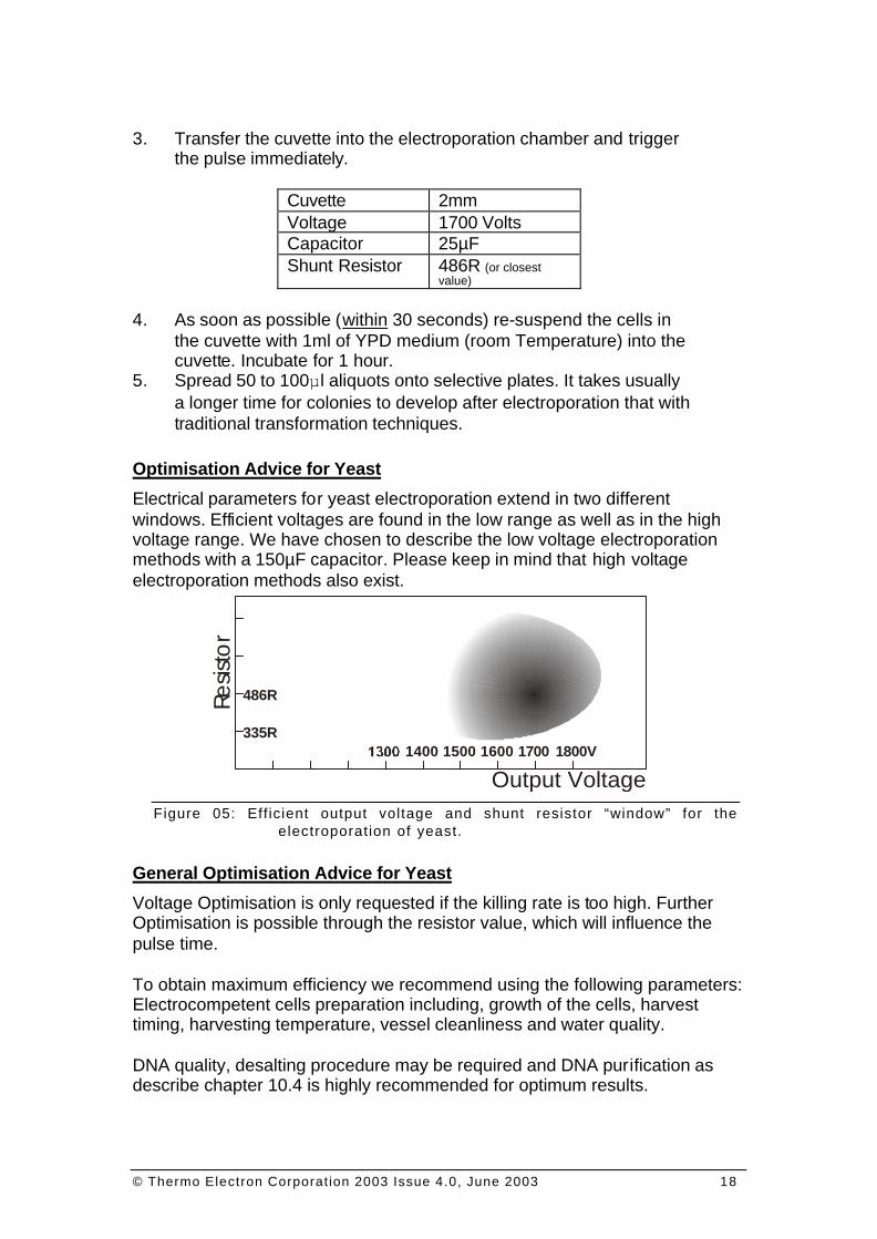
3. Transfer the cuvette into the electroporation chamber and trigger
the pulse immediately.
Cuvette 2mm Voltage 1700 Volts Capacitor 25µF Shunt Resistor 486R (or closest
value)
4. As soon as possible (within 30 seconds) re-suspend the cells in the cuvette with 1ml of YPD medium (room Temperature) into the cuvette. Incubate for 1 hour.
5. Spread 50 to 100µl aliquots onto selective plates. It takes usually a longer time for colonies to develop after electroporation that with traditional transformation techniques.
Optimisation Advice for Yeast
Electrical parameters for yeast electroporation extend in two different windows. Efficient voltages are found in the low range as well as in the high voltage range. We have chosen to describe the low voltage electroporation methods with a 150µF capacitor. Please keep in mind that high voltage electroporation methods also exist.
Figure 05: Eff icient output voltage and shunt resistor “window” for the electroporation of yeast.
General Optimisation Advice for Yeast
Voltage Optimisation is only requested if the killing rate is too high. Further Optimisation is possible through the resistor value, which will influence the pulse time. To obtain maximum efficiency we recommend using the following parameters: Electrocompetent cells preparation including, growth of the cells, harvest timing, harvesting temperature, vessel cleanliness and water quality. DNA quality, desalting procedure may be required and DNA purification as describe chapter 10.4 is highly recommended for optimum results.
Resis
tor
486R
335R
Output Voltage1600 1700 1800V1400 1500
© Thermo Electron Corporation 2003 Issue 4.0, June 2003 19
Timing and ice temperature during cell preparation and electroporation. Post electroporation events including timing and the quality of the outgrowth medium. Electroporated cells must be transferred within 30 seconds following the pulse into fresh outgrowth medium. Water quality is important; we recommend you only use freshly prepared 18MΩ, stored in detergent free cleanliness vessels, or better in disposable vessel. Chemicals grade. All chemicals used should be dedicated to cells culture and preparation and should be of molecular biology grade. Troubleshooting ~ Yeast Electroporation
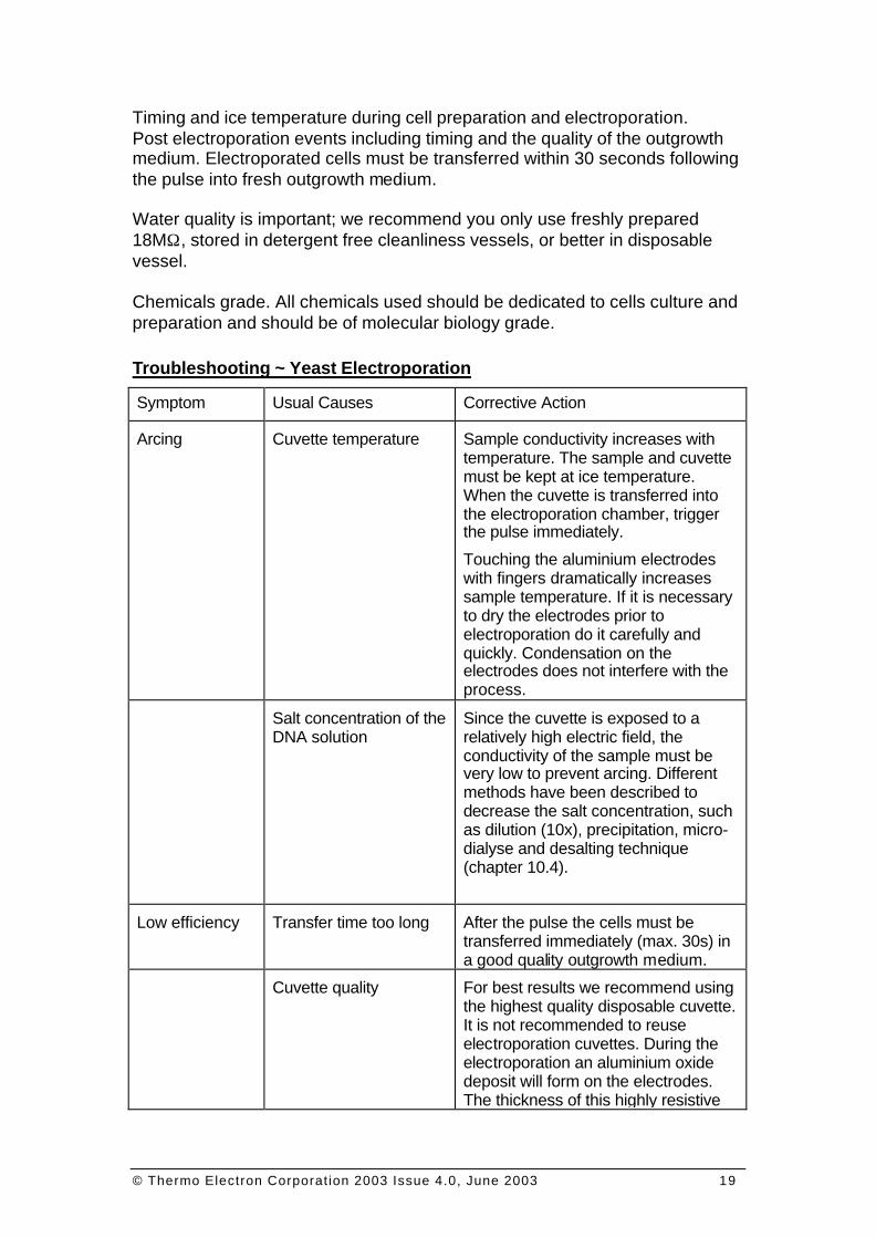
Symptom Usual Causes Corrective Action
Arcing Cuvette temperature Sample conductivity increases with temperature. The sample and cuvette must be kept at ice temperature. When the cuvette is transferred into the electroporation chamber, trigger the pulse immediately.
Touching the aluminium electrodes with fingers dramatically increases sample temperature. If it is necessary to dry the electrodes prior to electroporation do it carefully and quickly. Condensation on the electrodes does not interfere with the process.
Salt concentration of the DNA solution
Since the cuvette is exposed to a relatively high electric field, the conductivity of the sample must be very low to prevent arcing. Different methods have been described to decrease the salt concentration, such as dilution (10x), precipitation, micro-dialyse and desalting technique (chapter 10.4).
Low efficiency Transfer time too long After the pulse the cells must be transferred immediately (max. 30s) in a good quality outgrowth medium.
Cuvette quality For best results we recommend using the highest quality disposable cuvette. It is not recommended to reuse electroporation cuvettes. During the electroporation an aluminium oxide deposit will form on the electrodes. The thickness of this highly resistive
© Thermo Electron Corporation 2003 Issue 4.0, June 2003 20
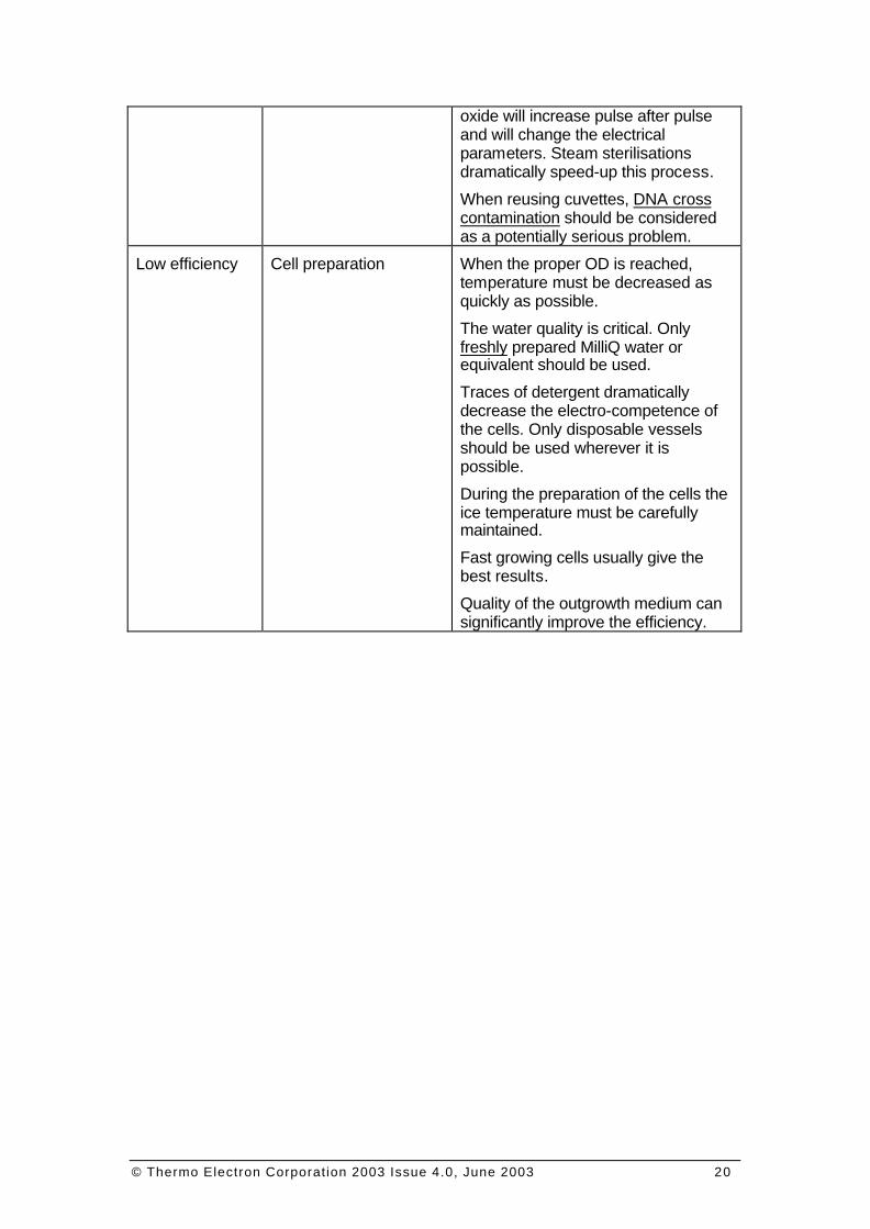
oxide will increase pulse after pulse and will change the electrical parameters. Steam sterilisations dramatically speed-up this process.
When reusing cuvettes, DNA cross contamination should be considered as a potentially serious problem.
Low efficiency Cell preparation When the proper OD is reached, temperature must be decreased as quickly as possible.
The water quality is critical. Only freshly prepared MilliQ water or equivalent should be used.
Traces of detergent dramatically decrease the electro-competence of the cells. Only disposable vessels should be used wherever it is possible.
During the preparation of the cells the ice temperature must be carefully maintained.
Fast growing cells usually give the best results.
Quality of the outgrowth medium can significantly improve the efficiency.
© Thermo Electron Corporation 2003 Issue 4.0, June 2003 21
THERMO ELECTRON ELECTROPORATION
OPTIMISATION GUIDE
CHAPTER VI: SPECIAL APPLICATIONS
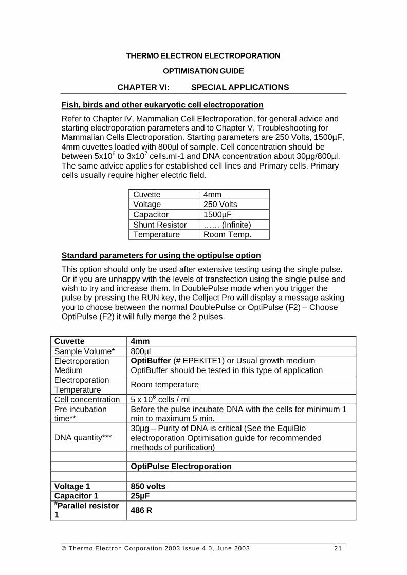
Fish, birds and other eukaryotic cell electroporation
Refer to Chapter IV, Mammalian Cell Electroporation, for general advice and starting electroporation parameters and to Chapter V, Troubleshooting for Mammalian Cells Electroporation. Starting parameters are 250 Volts, 1500µF, 4mm cuvettes loaded with 800µl of sample. Cell concentration should be between 5x10⁶ to 3x10⁷ cells.ml-1 and DNA concentration about 30µg/800µl. The same advice applies for established cell lines and Primary cells. Primary cells usually require higher electric field.
Cuvette 4mm Voltage 250 Volts Capacitor 1500µF Shunt Resistor …… (Infinite) Temperature Room Temp.
Standard parameters for using the optipulse option
This option should only be used after extensive testing using the single pulse. Or if you are unhappy with the levels of transfection using the single pulse and wish to try and increase them. In DoublePulse mode when you trigger the pulse by pressing the RUN key, the Cellject Pro will display a message asking you to choose between the normal DoublePulse or OptiPulse (F2) – Choose OptiPulse (F2) it will fully merge the 2 pulses.
Cuvette 4mm Sample Volume* 800µl Electroporation Medium
OptiBuffer (# EPEKITE1) or Usual growth medium OptiBuffer should be tested in this type of application
Electroporation Temperature
Room temperature
Cell concentration 5 x 10⁶ cells / ml Pre incubation time**
Before the pulse incubate DNA with the cells for minimum 1 min to maximum 5 min.
DNA quantity*** 30µg – Purity of DNA is critical (See the EquiBio electroporation Optimisation guide for recommended methods of purification)
OptiPulse Electroporation Voltage 1 850 volts Capacitor 1 25µF #Parallel resistor 1 486 R
© Thermo Electron Corporation 2003 Issue 4.0, June 2003 22
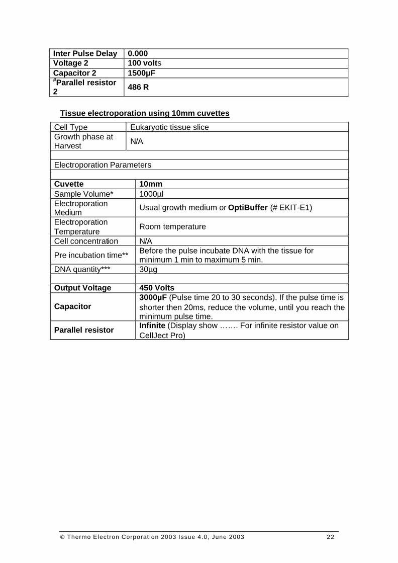
Inter Pulse Delay 0.000 Voltage 2 100 volts Capacitor 2 1500µF #Parallel resistor 2 486 R
Tissue electroporation using 10mm cuvettes
Cell Type Eukaryotic tissue slice Growth phase at Harvest N/A
Electroporation Parameters Cuvette 10mm Sample Volume* 1000µl Electroporation Medium
Usual growth medium or OptiBuffer (# EKIT-E1)
Electroporation Temperature
Room temperature
Cell concentration N/A
Pre incubation time** Before the pulse incubate DNA with the tissue for minimum 1 min to maximum 5 min.
DNA quantity*** 30µg Output Voltage 450 Volts
Capacitor 3000µF (Pulse time 20 to 30 seconds). If the pulse time is shorter then 20ms, reduce the volume, until you reach the minimum pulse time.
Parallel resistor Infinite (Display show ……. For infinite resistor value on CellJect Pro)
© Thermo Electron Corporation 2003 Issue 4.0, June 2003 23
THERMO ELECTRON ELECTROPORATION
OPTIMISATION GUIDE
CHAPTER VII: INTACT PLANT ELECTROPORATION
Plant Preparation
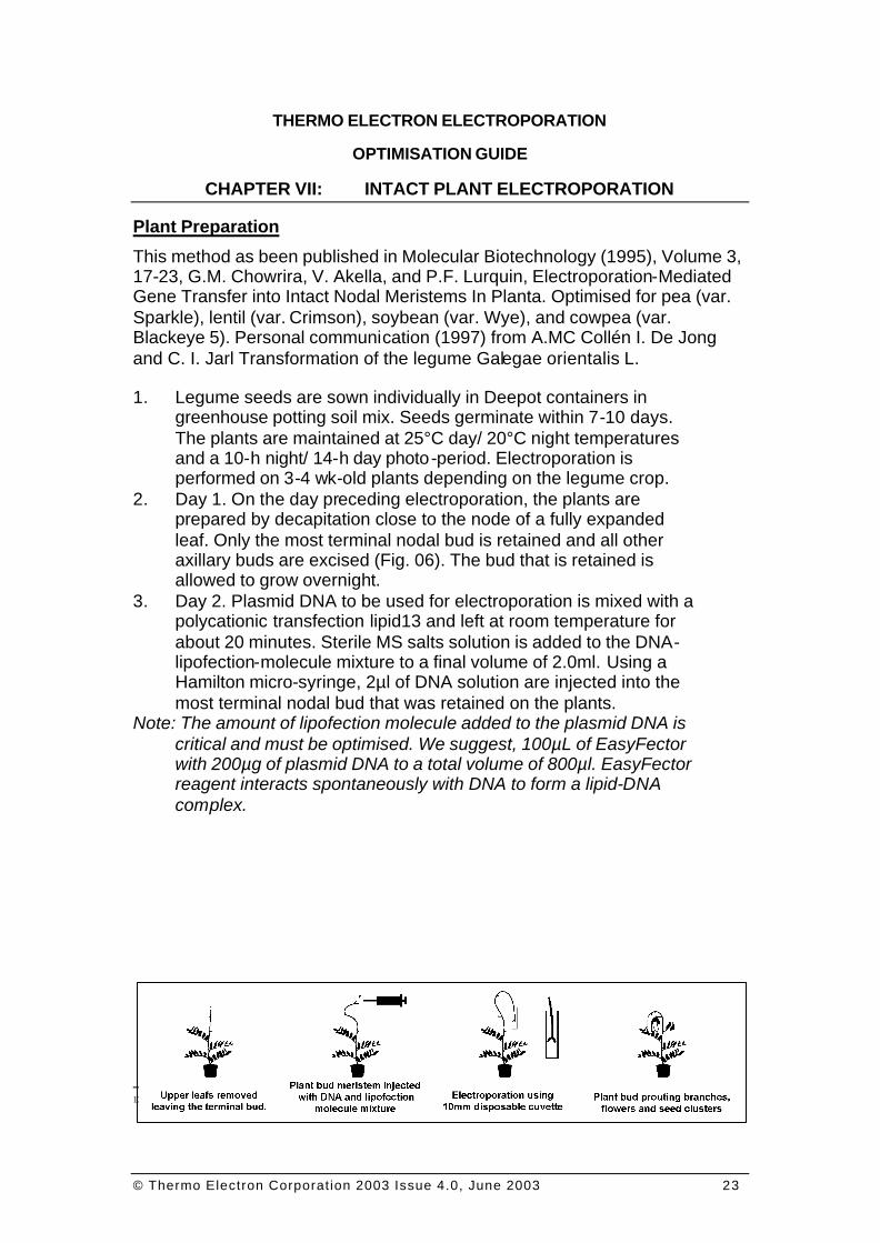
This method as been published in Molecular Biotechnology (1995), Volume 3, 17-23, G.M. Chowrira, V. Akella, and P.F. Lurquin, Electroporation-Mediated Gene Transfer into Intact Nodal Meristems In Planta. Optimised for pea (var. Sparkle), lentil (var. Crimson), soybean (var. Wye), and cowpea (var. Blackeye 5). Personal communication (1997) from A.MC Collén I. De Jong and C. I. Jarl Transformation of the legume Galegae orientalis L. 1. Legume seeds are sown individually in Deepot containers in
greenhouse potting soil mix. Seeds germinate within 7-10 days. The plants are maintained at 25°C day/ 20°C night temperatures and a 10-h night/ 14-h day photo-period. Electroporation is performed on 3-4 wk-old plants depending on the legume crop.
2. Day 1. On the day preceding electroporation, the plants are prepared by decapitation close to the node of a fully expanded leaf. Only the most terminal nodal bud is retained and all other axillary buds are excised (Fig. 06). The bud that is retained is allowed to grow overnight.
3. Day 2. Plasmid DNA to be used for electroporation is mixed with a polycationic transfection lipid13 and left at room temperature for about 20 minutes. Sterile MS salts solution is added to the DNA-lipofection-molecule mixture to a final volume of 2.0ml. Using a Hamilton micro-syringe, 2µl of DNA solution are injected into the most terminal nodal bud that was retained on the plants.
Note: The amount of lipofection molecule added to the plasmid DNA is critical and must be optimised. We suggest, 100µL of EasyFector with 200µg of plasmid DNA to a total volume of 800µl. EasyFector reagent interacts spontaneously with DNA to form a lipid-DNA complex.
13 Thermo commercialises 2 polycationic lipids: EasyFector cat. # ETR-E1 and PrimeFector cat. # ETR-P1.
© Thermo Electron Corporation 2003 Issue 4.0, June 2003 24
F IGURE 06: INTACT PLANT BUD ELECTROPORATION.
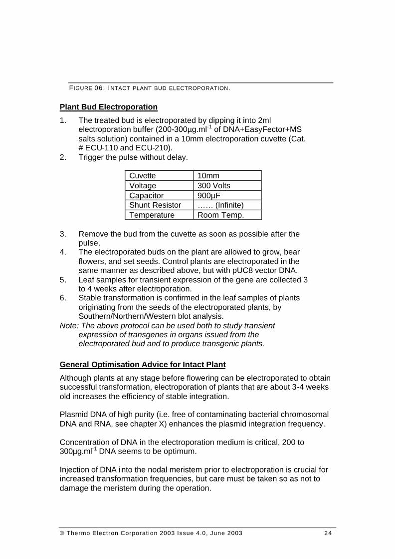
Plant Bud Electroporation
1. The treated bud is electroporated by dipping it into 2ml electroporation buffer (200-300µg.ml-1 of DNA+EasyFector+MS salts solution) contained in a 10mm electroporation cuvette (Cat. # ECU-110 and ECU-210).
2. Trigger the pulse without delay.
Cuvette 10mm Voltage 300 Volts Capacitor 900µF Shunt Resistor …… (Infinite) Temperature Room Temp.
3. Remove the bud from the cuvette as soon as possible after the
pulse. 4. The electroporated buds on the plant are allowed to grow, bear
flowers, and set seeds. Control plants are electroporated in the same manner as described above, but with pUC8 vector DNA.
5. Leaf samples for transient expression of the gene are collected 3 to 4 weeks after electroporation.
6. Stable transformation is confirmed in the leaf samples of plants originating from the seeds of the electroporated plants, by Southern/Northern/Western blot analysis.
Note: The above protocol can be used both to study transient expression of transgenes in organs issued from the electroporated bud and to produce transgenic plants.
General Optimisation Advice for Intact Plant
Although plants at any stage before flowering can be electroporated to obtain successful transformation, electroporation of plants that are about 3-4 weeks old increases the efficiency of stable integration. Plasmid DNA of high purity (i.e. free of contaminating bacterial chromosomal DNA and RNA, see chapter X) enhances the plasmid integration frequency. Concentration of DNA in the electroporation medium is critical, 200 to 300µg.ml-1 DNA seems to be optimum. Injection of DNA into the nodal meristem prior to electroporation is crucial for increased transformation frequencies, but care must be taken so as not to damage the meristem during the operation.

© Thermo Electron Corporation 2003 Issue 4.0, June 2003 25
Following electroporation, although the plant is recovering and the electroporated meristem is growing to form a branch, growth from all the auxiliary buds below the electroporated meristem should be discouraged by excising them regularly.

© Thermo Electron Corporation 2003 Issue 4.0, June 2003 26
© Thermo Electron Corporation 2003 Issue 4.0, June 2003 27
THERMO ELECTRON ELECTROPORATION
OPTIMISATION GUIDE
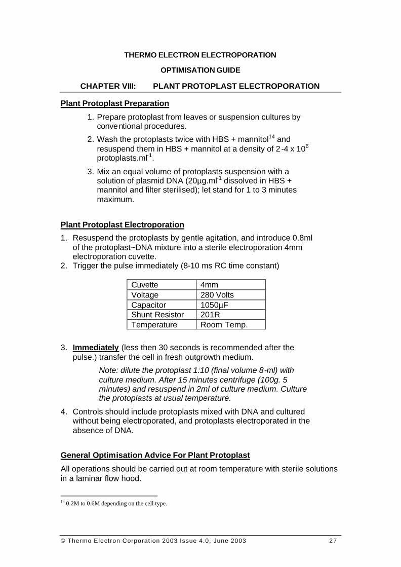
CHAPTER VIII: PLANT PROTOPLAST ELECTROPORATION
Plant Protoplast Preparation
1. Prepare protoplast from leaves or suspension cultures by conventional procedures.
2. Wash the protoplasts twice with HBS + mannitol14 and resuspend them in HBS + mannitol at a density of 2 -4 x 10⁶ protoplasts.ml-1.
3. Mix an equal volume of protoplasts suspension with a solution of plasmid DNA (20µg.ml-1 dissolved in HBS + mannitol and filter sterilised); let stand for 1 to 3 minutes maximum.
Plant Protoplast Electroporation
1. Resuspend the protoplasts by gentle agitation, and introduce 0.8ml of the protoplast~DNA mixture into a sterile electroporation 4mm electroporation cuvette.
2. Trigger the pulse immediately (8-10 ms RC time constant)
Cuvette 4mm Voltage 280 Volts Capacitor 1050µF Shunt Resistor 201R Temperature Room Temp.
3. Immediately (less then 30 seconds is recommended after the pulse.) transfer the cell in fresh outgrowth medium.
Note: dilute the protoplast 1:10 (final volume 8-ml) with culture medium. After 15 minutes centrifuge (100g. 5 minutes) and resuspend in 2ml of culture medium. Culture the protoplasts at usual temperature.
4. Controls should include protoplasts mixed with DNA and cultured without being electroporated, and protoplasts electroporated in the absence of DNA.
General Optimisation Advice For Plant Protoplast
All operations should be carried out at room temperature with sterile solutions in a laminar flow hood.
14 0.2M to 0.6M depending on the cell type.
© Thermo Electron Corporation 2003 Issue 4.0, June 2003 28
Water quality is important; we recommend you only use freshly prepared 18MΩ, stored in detergent free clean vessels, or better in a disposable vessel.
All chemicals used should be dedicated to cell culture and preparation and should be a molecular biology grade. DNA quality is critical. We only recommend the CsCl centrifugation followed by the NaCl centrifugation (chapter 10.2 and 10.3). Other purification techniques to prepare transfection grade DNA are slowly emerging.
© Thermo Electron Corporation 2003 Issue 4.0, June 2003 29
THERMO ELECTRON ELECTROPORATION
OPTIMISATION GUIDE
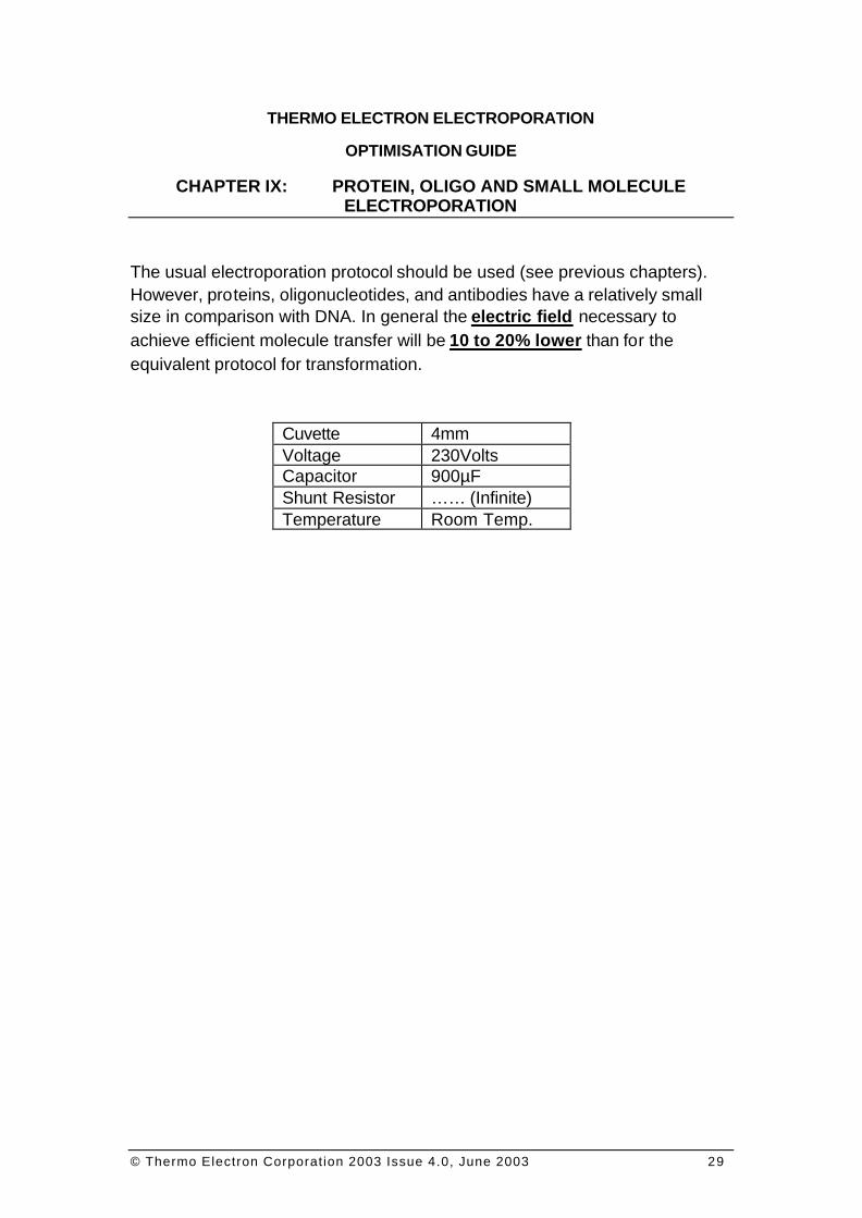
CHAPTER IX: PROTEIN, OLIGO AND SMALL MOLECULE ELECTROPORATION
The usual electroporation protocol should be used (see previous chapters). However, proteins, oligonucleotides, and antibodies have a relatively small size in comparison with DNA. In general the electric field necessary to achieve efficient molecule transfer will be 10 to 20% lower than for the equivalent protocol for transformation.
Cuvette 4mm Voltage 230Volts Capacitor 900µF Shunt Resistor …… (Infinite) Temperature Room Temp.

© Thermo Electron Corporation 2003 Issue 4.0, June 2003 30
THERMO ELECTRON ELECTROPORATION
© Thermo Electron Corporation 2003 Issue 4.0, June 2003 31
OPTIMISATION GUIDE
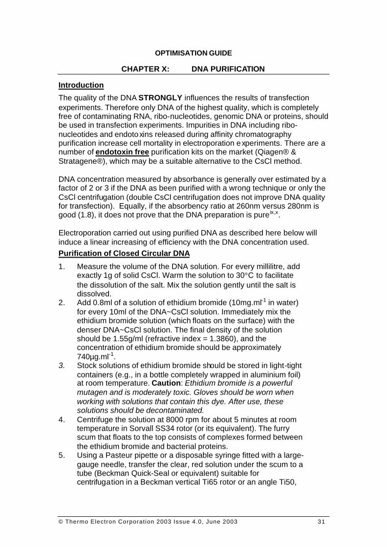
CHAPTER X: DNA PURIFICATION
Introduction
The quality of the DNA STRONGLY influences the results of transfection experiments. Therefore only DNA of the highest quality, which is completely free of contaminating RNA, ribo-nucleotides, genomic DNA or proteins, should be used in transfection experiments. Impurities in DNA including ribo-nucleotides and endotoxins released during affinity chromatography purification increase cell mortality in electroporation experiments. There are a number of endotoxin free purification kits on the market (Qiagen® & Stratagene®), which may be a suitable alternative to the CsCl method. DNA concentration measured by absorbance is generally over estimated by a factor of 2 or 3 if the DNA as been purified with a wrong technique or only the CsCl centrifugation (double CsCl centrifugation does not improve DNA quality for transfection). Equally, if the absorbency ratio at 260nm versus 280nm is good (1.8), it does not prove that the DNA preparation is pure ix,x. Electroporation carried out using purified DNA as described here below will induce a linear increasing of efficiency with the DNA concentration used. Purification of Closed Circular DNA
1. Measure the volume of the DNA solution. For every millilitre, add exactly 1g of solid CsCl. Warm the solution to 30°C to facilitate the dissolution of the salt. Mix the solution gently until the salt is dissolved.
2. Add 0.8ml of a solution of ethidium bromide (10mg.ml-1 in water) for every 10ml of the DNA~CsCl solution. Immediately mix the ethidium bromide solution (which floats on the surface) with the denser DNA~CsCl solution. The final density of the solution should be 1.55g/ml (refractive index = 1.3860), and the concentration of ethidium bromide should be approximately 740µg.ml-1.
3. Stock solutions of ethidium bromide should be stored in light-tight containers (e.g., in a bottle completely wrapped in aluminium foil) at room temperature. Caution: Ethidium bromide is a powerful mutagen and is moderately toxic. Gloves should be worn when working with solutions that contain this dye. After use, these solutions should be decontaminated.
4. Centrifuge the solution at 8000 rpm for about 5 minutes at room temperature in Sorvall SS34 rotor (or its equivalent). The furry scum that floats to the top consists of complexes formed between the ethidium bromide and bacterial proteins.
5. Using a Pasteur pipette or a disposable syringe fitted with a large-gauge needle, transfer the clear, red solution under the scum to a tube (Beckman Quick-Seal or equivalent) suitable for centrifugation in a Beckman vertical Ti65 rotor or an angle Ti50,
© Thermo Electron Corporation 2003 Issue 4.0, June 2003 32
Ti65, or Ti70 rotor (or their equivalent). Fill the remainder of the tube with light paraffin oil and seal the tube.
6. Centrifuge the density gradients at 45,000 rpm for 16 hours (Vti65), 45,000 rpm for 48 hours (Ti50), 60,000 rpm for 24 hours (Ti65), or 60,000 rpm for 24 hours (Ti70.1) at 20°C.
7. Two bands of DNA, located in the centre of the gradient should be visible in ordinary light. The upper band, which usually contains less material, consists of linear bacterial (chromosomal) DNA and nicked circular plasmid DNA; the lower band consists of closed circular plasmid DNA. The deep-red pellet on the bottom of the tube consists of ethidium bromide~RNA complexes. The material between the CsCl solution and the paraffin oil is protein. NOTE: CsCl-Ethidium bromide gradients in Beckman Quick-Seal tubes can accommodate up to 4mg of closed circular plasmid DNA without becoming overloaded. If more plasmid DNA is present, it spreads into a wide band that overlaps with chromosomal DNA. This problem, which arises only with plasmids that replicate to extremely high levels, can be avoided by dividing such plasmid preparations between two gradients. If overloading does occur, collect the entire band of DNA, adjust the volume of the solution to 15 ml with CsCl solution (ρ = 1.58g.ml-1), and re-centrifuge the DNA to equilibrium in two centrifuge tubes.
8. Collect the bands of DNA. Insert a 21-gauge hypodermic needle into the top of the tube to allow air to enter. To minimise the possibility of contamination, first collect the upper band (chromosomal DNA) through an 18-gauge hypodermic needle as follows; Carefully wipe the outside of the tube with ethanol to remove any grease or oil, and then attach a piece of Scotch Tape to the outside of the tube. Insert an 18-gauge hypodermic needle (bevelled side up) into the tube through the tape so that the open, bevelled side of the needle is positioned just below the band of chromosomal DNA and parallel to it. Collect the viscous DNA into a disposable tube, and then seal the end of the hypodermic needle with a plug of modelling clay. Leaving the second needle in place, insert a third hypodermic needle (18-gauge) through the tape and collect the lower band of plasmid DNA into a glass or plastic tube. Remove ethidium .
Removal of RNA From Preparation of Plasmid DNA
For some it is essential to obtain DNA preparations that are free of contaminating RNA. Although the weight of such contaminants in plasmid DNA prepared by equilibrium centrifugation in CsCl-Ethidium bromide gradients is small, the number of RNA molecules can be relatively large and can contribute significantly to the total number of 5’ termini. RNA can be removed from plasmid preparations by the following method. This is an unpublished protocol of B. Seed. 1. Add 0.1 volume of 3M sodium acetate (pH 5.2) and precipitate the
nucleic acids with 2 volumes of ethanol for 30 minutes at 4°C.
© Thermo Electron Corporation 2003 Issue 4.0, June 2003 33
2. Recover the nucleic acids by centrifugation at > 10,000g for 15 minutes at 4°C. Drain off as much of the supernatant as possible, and then store the open tube on the bench to allow the last traces of ethanol to evaporate.
3. Dissolve the pellet in TE (pH 8.0) at a concentration of at least 100µg.ml-1.
4. Add DNAse-free pancreatic RNAse (see Appendix B) to a final concentration of 10µg.ml-1.
5. Incubate the mixture for 1 hour at room temperature. 6. Add 4ml of TE (pH 8.0) containing 1M NaCl to a Beckman
SW50.1 centrifuge tube or its equivalent). Using an automatic pipetting device equipped with a disposable tip, layer up to 1ml of the RNAse-treated plasmid preparation on top of the 1 M NaCl solution. If necessary, fill the tube with TE (pH 8.0). Centrifuge at 40,000 rpm for 6 hours at 20°C in a Beckman SW50.1 rotor (or its equivalent). The plasmid DNA sediments drop to the bottom of the tube while the ribo-oligonucleotides remain in the supernatant.
7. Discard the supernatant. Re-dissolve the pellet of plasmid DNA in 5.0ml of TE (pH 8.0). Add 50µl of 3M sodium acetate and recover the DNA by precipitation with 2 volumes of ethanol for 10 minutes at 4°C and centrifugation at >10,000g for 15 minutes at 4°C.
Desalting of Ligation Mix
This method has been published in BioTechniques 21:1024 (December 1996) by Alexey M. Atrazhev and John F. Elliott. Since the cuvette is exposed to an electric field of 10-18 kV/cm, the conductivity of the sample must be very low to prevent arcing. For example, a maximum of 0.3-0.5µl of a standard ligation mixture (typically 10-50µl total volume) can be added directly to 20µL of electrocompetent cells before arcing begins to occur. Various protocols have beep proposed to desalt DNA in a small volume, including: traditional ethanol-precipitation, rinsing and re-suspension; gel filtration on micro-columns or drop dialysis through membranes. This method requires minimal manipulation of the DNA, which is a significant advantage for ligation involving large DNA fragments. 1. Fill an Eppendorf tube with 1.5ml of molten 1% agarose in 100mM
glucose. 2. Before gelling, vertically immerse a 200µl plastic micropipette tip
into the surface of the agarose through a pre-formed hole in the lid (created for example by drilling a small hole).
3. After the agarose solidifies remove the tip to leave a conical shaped well of approximately 30-l00µl volume, depending on how far the tip has been immersed into the agarose.
4. Load the completed ligation reaction into the "well" using a micropipette and incubated for 90 minutes on ice to let the salt diffuse into the agarose.
© Thermo Electron Corporation 2003 Issue 4.0, June 2003 34
5. Carefully remove the liquid mixture from the well, and a portion of it is directly electroporated into bacteria.
THERMO ELECTRON ELECTROPORATION OPTIMISATION GUIDE
CHAPTER XI: DOUBLE & OPTIPULSE
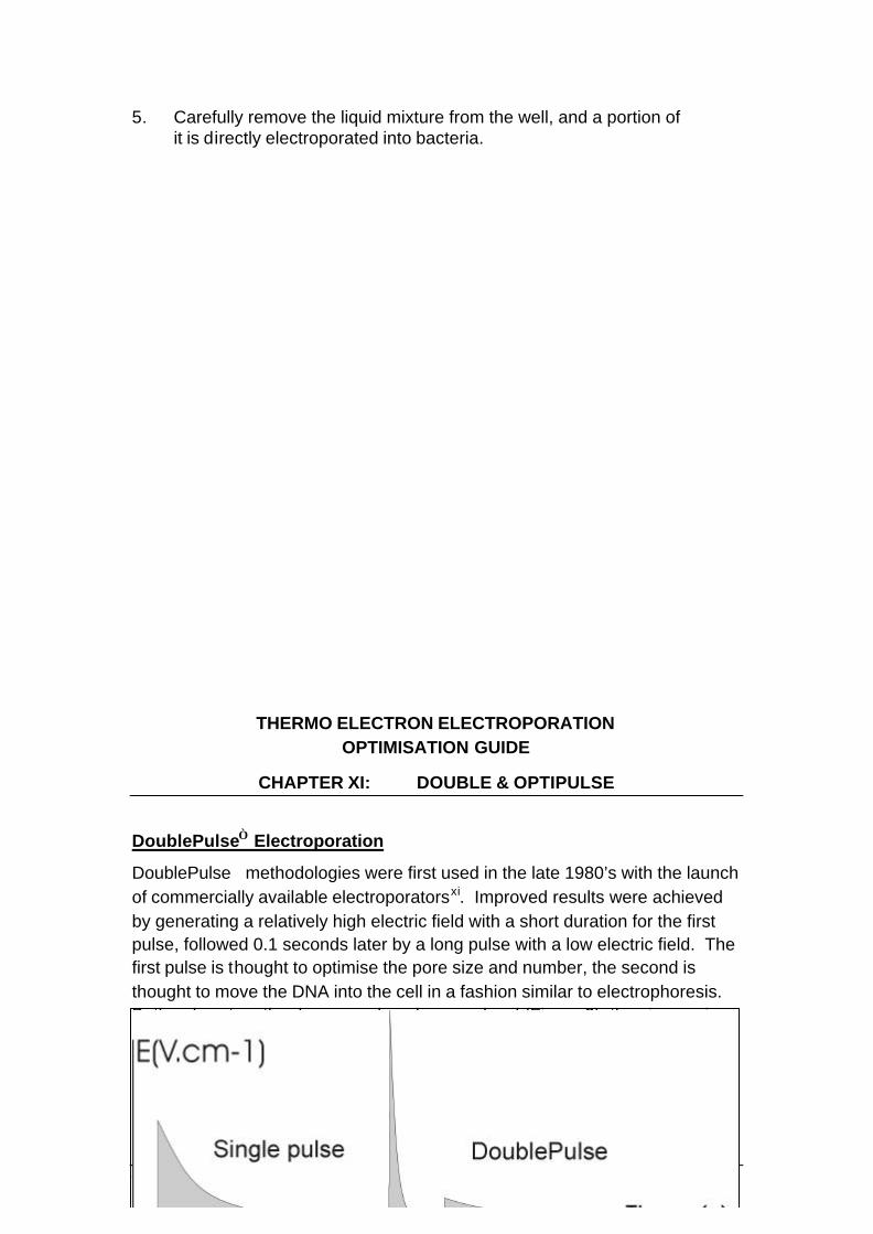
DoublePulse Electroporation
DoublePulse methodologies were first used in the late 1980’s with the launch of commercially available electroporatorsxi. Improved results were achieved by generating a relatively high electric field with a short duration for the first pulse, followed 0.1 seconds later by a long pulse with a low electric field. The first pulse is thought to optimise the pore size and number, the second is thought to move the DNA into the cell in a fashion similar to electrophoresis. Both pulses together have a reduced energy level (Figure 2), thus increasing cell survival.
Figure 2: Single pulse and DoublePulse electroporation.
© Thermo Electron Corporation 2003 Issue 4.0, June 2003 35
Energy Level Single Pulse versus DoublePulse
Energy levels used can be calculated using the following formula:
P=0.5 x CV2
Single Pulse: Typical parameters = 250 volts and 1000µF
P= 0.5 x 1000.10-6 x 2502 = 31.25 Joule
DoublePulse: Typical parameters = 750 volts and 25µF & 100 volts and 1500µF P= (0.5 x 25.10-6 x 7502) + (0.5 x 1,5.10-3 x 1002) = 14.53 J
From these figures it can clearly be seen that the energy level used from this example is 50% of a single pulse method.
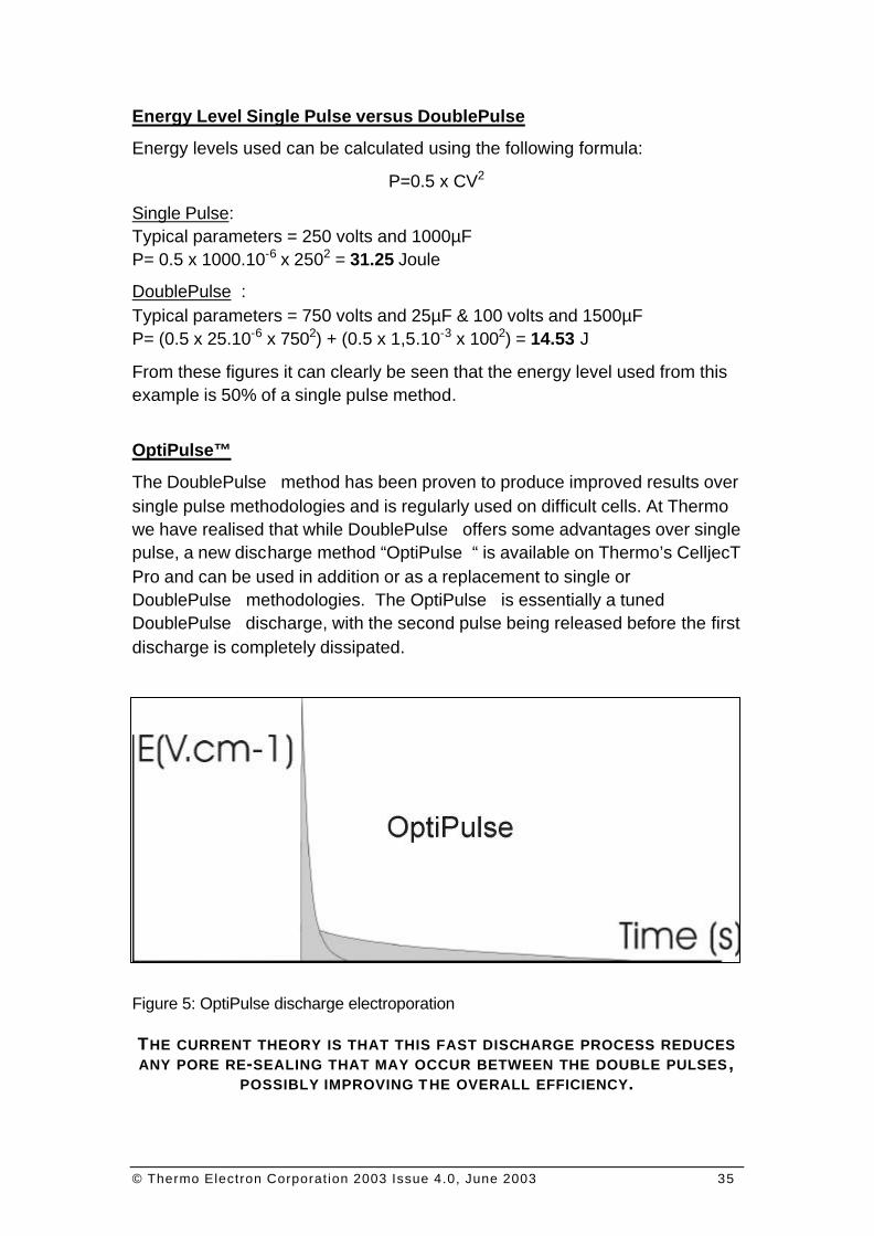
OptiPulse™
The DoublePulse method has been proven to produce improved results over single pulse methodologies and is regularly used on difficult cells. At Thermo we have realised that while DoublePulse offers some advantages over single pulse, a new discharge method “OptiPulse“ is available on Thermo’s CelljecT Pro and can be used in addition or as a replacement to single or DoublePulse methodologies. The OptiPulse is essentially a tuned DoublePulse discharge, with the second pulse being released before the first discharge is completely dissipated.
Figure 5: OptiPulse discharge electroporation THE CURRENT THEORY IS THAT THIS FAST DISCHARGE PROCESS REDUCES ANY PORE RE-SEALING THAT MAY OCCUR BETWEEN THE DOUBLE PULSES ,
POSSIBLY IMPROVING T HE OVERALL EFFICIENCY.
© Thermo Electron Corporation 2003 Issue 4.0, June 2003 36
THERMO ELECTRON ELECTROPORATION OPTIMISATION GUIDE
CHAPTER XII: MEDIUM AND BUFFERS
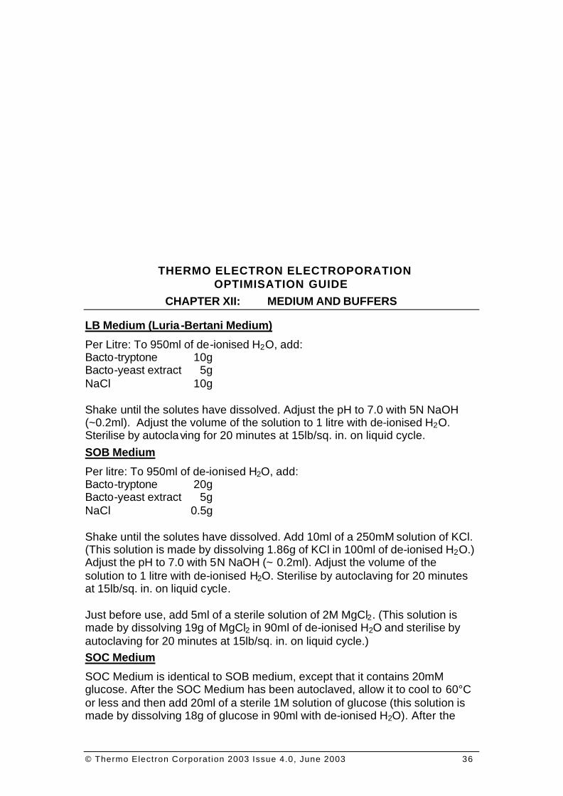
LB Medium (Luria-Bertani Medium)
Per Litre: To 950ml of de-ionised H2O, add: Bacto-tryptone 10g Bacto-yeast extract 5g NaCl 10g Shake until the solutes have dissolved. Adjust the pH to 7.0 with 5N NaOH (~0.2ml). Adjust the volume of the solution to 1 litre with de-ionised H2O. Sterilise by autoclaving for 20 minutes at 15lb/sq. in. on liquid cycle. SOB Medium
Per litre: To 950ml of de-ionised H2O, add: Bacto-tryptone 20g Bacto-yeast extract 5g NaCl 0.5g Shake until the solutes have dissolved. Add 10ml of a 250mM solution of KCl. (This solution is made by dissolving 1.86g of KCl in 100ml of de-ionised H2O.) Adjust the pH to 7.0 with 5N NaOH (~ 0.2ml). Adjust the volume of the solution to 1 litre with de-ionised H2O. Sterilise by autoclaving for 20 minutes at 15lb/sq. in. on liquid cycle. Just before use, add 5ml of a sterile solution of 2M MgCl2. (This solution is made by dissolving 19g of MgCl2 in 90ml of de-ionised H2O and sterilise by autoclaving for 20 minutes at 15lb/sq. in. on liquid cycle.) SOC Medium
SOC Medium is identical to SOB medium, except that it contains 20mM glucose. After the SOC Medium has been autoclaved, allow it to cool to 60°C or less and then add 20ml of a sterile 1M solution of glucose (this solution is made by dissolving 18g of glucose in 90ml with de-ionised H2O). After the
© Thermo Electron Corporation 2003 Issue 4.0, June 2003 37
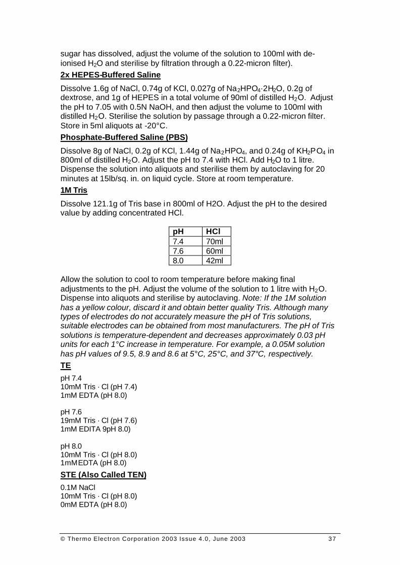
sugar has dissolved, adjust the volume of the solution to 100ml with de-ionised H2O and sterilise by filtration through a 0.22-micron filter). 2x HEPES-Buffered Saline
Dissolve 1.6g of NaCl, 0.74g of KCl, 0.027g of Na2HPO4·2H2O, 0.2g of dextrose, and 1g of HEPES in a total volume of 90ml of distilled H2O. Adjust the pH to 7.05 with 0.5N NaOH, and then adjust the volume to 100ml with distilled H2O. Sterilise the solution by passage through a 0.22-micron filter. Store in 5ml aliquots at -20°C. Phosphate-Buffered Saline (PBS)
Dissolve 8g of NaCl, 0.2g of KCl, 1.44g of Na2HPO4, and 0.24g of KH2PO4 in 800ml of distilled H2O. Adjust the pH to 7.4 with HCl. Add H2O to 1 litre. Dispense the solution into aliquots and sterilise them by autoclaving for 20 minutes at 15lb/sq. in. on liquid cycle. Store at room temperature. 1M Tris
Dissolve 121.1g of Tris base in 800ml of H2O. Adjust the pH to the desired value by adding concentrated HCl.
pH HCl 7.4 70ml 7.6 60ml 8.0 42ml
Allow the solution to cool to room temperature before making final adjustments to the pH. Adjust the volume of the solution to 1 litre with H2O. Dispense into aliquots and sterilise by autoclaving. Note: If the 1M solution has a yellow colour, discard it and obtain better quality Tris. Although many types of electrodes do not accurately measure the pH of Tris solutions, suitable electrodes can be obtained from most manufacturers. The pH of Tris solutions is temperature-dependent and decreases approximately 0.03 pH units for each 1°C increase in temperature. For example, a 0.05M solution has pH values of 9.5, 8.9 and 8.6 at 5°C, 25°C, and 37°C, respectively. TE
pH 7.4 10mM Tris · Cl (pH 7.4) 1mM EDTA (pH 8.0) pH 7.6 19mM Tris · Cl (pH 7.6) 1mM EDITA 9pH 8.0) pH 8.0 10mM Tris · Cl (pH 8.0) 1mM EDTA (pH 8.0) STE (Also Called TEN)
0.1M NaCl 10mM Tris · Cl (pH 8.0) 0mM EDTA (pH 8.0)

© Thermo Electron Corporation 2003 Issue 4.0, June 2003 38
STET
0.1M NaCl 10mM Tris · Cl (pH 8.0) 1mM EDTA 9pH 8.0) 5% Triton X-100
TNT
10mM Tris · Cl (pH 8.0) 150mM NaCl 0.05% Tween 20

© Thermo Electron Corporation 2003 Issue 4.0, June 2003 39
THERMO ELECTRON ELECTROPORATION
© Thermo Electron Corporation 2003 Issue 4.0, June 2003 40
OPTIMISATION GUIDE
CHAPTER XIII: GENERAL INFORMATION
The Cleanliness of the Glassware and Plasticware.
Because the presence of trace amounts of detergent or other chemicals greatly reduces the efficiency of transformation, it is best to set aside a batch of glassware that is used for no other purpose than transfection. This glassware should be washed and rinsed by hand, filled with pure water (MilliQ or equivalent), and sterilised by autoclaving. The water should be discarded just before the glassware is used. Transfection Principle
This is the delivery of foreign molecules such as DNA or RNA into living cells. This technique has become a powerful tool for the study and control of gene expression. Different transfection techniques can be used; transient transfection and stable transfection. Transient Transfection
When cells are transiently transfected, the DNA is introduced into the cell, but does not integrate into the chromosome. This means that many copies of the gene can be present. Transcription of the reporter gene can be analysed within 24 to 96 hours after introduction of the DNA. Transient transfection is most efficient when supercoiled plasmid DNA is used. Stable Transfection
With stable transfection, the transfected DNA is either integrated into the genome or maintained as an episome. Stable transfection involving integration of the DNA is most efficient when linearised plasmid DNA is used, since linearisation facilitates recombination of the DNA with the cell chromosome. Cells that have successfully integrated the DNA of interest can be distinguished by using detectable markers. Frequently used detectable markers are the genes encoding aminoglycoside phosphotransferase (APH; neor gene) or hygrornycin B phosphotransferase (HPH). Other detectable markers are the genes encoding adenosine deaminase (ADA), dihydrofolate reductase (DHFR), thymidine kinase or xanthine-guanine phosphoribosyl tranferase (XGPRT; gpt gene). Primary Cells and Cell Lines
Cells or cell lines vary greatly with respect to their growth behaviour and nutritional requirements. Optimisation of the cell culture work is therefore necessary to ensure that cells are healthy and in Prol condition for transfection. Primary Cell Culture
Primary cell cultures arise from the outgrowth of migrating cells from a piece of tissue or by enzymatic, chemical, or mechanical dispersal of the tissue. Primary cell cultures are morphologically most similar to the parent tissue.
© Thermo Electron Corporation 2003 Issue 4.0, June 2003 41
Finite Cell Line
Finite cell lines are formed after the first sub-culturing of a Primary cell culture, and can be propagated and sub-cultured several times. Established Cell Line
There is a limit to the number of generations that a finite cell line can be propagated. After that it will either die out or acquire a stable, heritable alteration, giving rise to an established cell line (i.e.: Hela cells). Adherent and Suspension Cells
Cell cultures or cell lines grow as an adherent layer(s) or in suspension depending on their origin. Adherent Cells
Adherent cells are anchorage-dependent and propagate as a mono or multi layer(s) attached to the culture vessel. This attachment is essential for proliferation. Most cells derived from tissues are anchorage-dependent. Suspension Cells
Suspension cells are able to survive and proliferate without attachment. Hematopoeïtic cells, transformed cell lines, and cells from malignant tumours can be grown in suspension. Media and Supplements
Media are composed of a mixture of essential salts, nutrients, and buffering agents. Alternatively, packaged premixed powders are available. Most media purchased are guaranteed to be mycoplasma and endotoxin free. Supplements to the media must include glutamine and can include non-essential amino acids, sodium pyruvate and antibiotics. Some common media include F12, DMEM, RPMI 1640, DMEM/F12, MEM, S-MEM. Serum
In most cases media are supplemented shortly before use with serum. Foetal calf serum (FCS) is often used, but for some applications less expensive sera like horse- or calf serum can be used. Generally serum is a partially undefined material, which contains growth and attachment factors and may show considerable variation in the ability to support growth of particular cells. Variations in the serum quality can also lead to variation in transfection efficiency. In general, it is advisable to test a small batch of serum from a reputable supplier with a control cell line and assay before performing transfection experiments. Once a given batch has been shown to yield satisfactory and reproducible results, additional sera from the same lot should be purchased. Transfection Methods
Of the variety of different transfection methods, DEAE-dextran, calcium phosphate, electroporation, and liposome-mediated transfection are the most commonly used. Each individual method has its characteristic advantages and disadvantages and the choice of transfection method strongly influences transfection results. If you are not sure of the most adequate technique do not hesitate to contact us for some advice.
© Thermo Electron Corporation 2003 Issue 4.0, June 2003 42
Plasmid DNA Quality
The quality of the plasmid DNA STRONGLY influences the results of transfection experiments. Therefore only plasmid DNA of the highest quality, which is completely free of contaminating RNA, genomic DNA or proteins, should be used. We consider that DNA purified as described in chapter 10 gives the best results. Conformation and Concentration of DNA
Although both linear and circular DNA can be transfected by electroporation, higher levels of stable transformation are obtained when linear DNA is used. Effective transfection has been obtained with concentrations of DNA ranging from 1µg/ml to 80µg/ml. Genetic Reporter Systems
After cloning a gene of interest, transfection is a useful tool to determine how cis-acting sequences, such as promoters and enhancers, and trans-acting factors, such as transcription factors, act together to control eukaryotic gene expression. The reporter gene provides an indirect way of measuring how such regulatory sequences influence gene expression. Reporter genes are also useful in serving as controls. Transfection efficiencies between transfection experiments can be standardised by comparing the expression of the reporter gene product. In choosing a suitable reporter system, several considerations should be taken into account. First, the reporter gene should be absent from the cells used in the study or easily distinguished from the native form of the gene. Second, the assay for the reporter gene product should be quick, easy, sensitive, and inexpensive. In particular, a broad linear range is important to enable detection of both small and large changes in the reporter gene expression. Finally, the presence of the reporter gene should not affect the physiology of the cells being used. Commonly Used Reporter Genes Chloramphenicol Acetyltransferase
The prokaryotic enzyme chloramphenicol acetyltransferase (CAT) is commonly used as a reporter. This enzyme catalyses the transfer of acetyl-groups from acetyl-coenzyrne-A to chloramphenicol. In the common CAT assay, cell lysates prepared from transfected cells are incubated with 14C-Iabeled chloramphenicol. The resulting acetylated and unacetylated forms of chloramphenicol are separated by thin-layer chromatography. A qualitative estimate of CAT activity can be obtained simply by exposing the plates to X-ray film. For quantitative analysis, the separated bands can be scraped from the thin-layer plate and the levels of radioactivity measured in a scintillation counter. Firefly Luciferase
Luciferase catalyses a bioluminescent reaction involving the substrate luciferin, ATP, Mg2+, and molecular oxygen. When these components are
© Thermo Electron Corporation 2003 Issue 4.0, June 2003 43
mixed with cell lysates containing luciferase, a flash of light is emitted. Light signals are detected using a luminometer or a liquid scintillation counter. B-Galactosidase
The prokaryotic enzyme B-galactosidase can be assayed calorimetrically using the substrate o-nitrophenyl-3-D-galactopyranoside (ONPG). The hydrolysis of ONPG by B-galactosidase yields a yellow-coloured product, o -nitrophenol, which can be measured photometrically. Human Growth Hormone (HGH)
The assay for human growth hormone is based on immprimalogical detection of hGH secreted by transfected cells. Specific 125I-Iabeled antibodies against hGH are used and results are monitored in a scintillation counter. Green Fluorescent Protein
Green fluorescent protein (GFP), originally isolated from the jellyfish Aequorea Victoria, has the ability to absorb blue light and emit green light. This unique protein can be expressed in mammalian cells and protein expression can be visually monitored in living cells. Although the system provides a convenient way to detect protein expression without a specific assay, quantitative analysis is limited. This reporter gene system is best suited for InSitu detection of gene expression, such as localisation studies of fusion proteins within cells. Other Reporter Systems
• Secreted alkaline phosphatase • 8-glucuronidase (GUS)
THERMO ELECTRON ELECTROPORATION OPTIMISATION GUIDE
CHAPTER XIV: ELECTRICAL BASICS
Electric Field
The electric field 15, E, is expressed in Volts per centimetre. It can be calculated with the following formula: E = V.d-1
15 For the Gram-negative bacteria E.Coli the electric field necessary to achieve good transformation efficiency is 12,5kV * cm -1. To achieve this electric field it will be necessary to set up the output voltage of the electroporation system at 2500V with 2mm cuvette (2500 * 0.2-1) or to 1250V with 1mm cuvette (1250 * 0.1-1).
© Thermo Electron Corporation 2003 Issue 4.0, June 2003 44
V is the output voltage (Volt) of the electroporation apparatus and d is the distance (centimetre) between the electrodes of the electroporation cuvette. Capacitor
Electronic components that usually look like a canister inside of which it is possible to store electrical charges (electrons). The unit to measure the capacity of a capacitor is called Farad (F). Practically all electroporation capacitor values will vary from a few µF to a couple of thousands µF. Pulse Energy
The energy (P) stored in a capacitor can be calculated with the following formula: P = 0.5.C.V2
The energy is expressed in Joule (J) while the capacitor is expressed in Farad and the voltage in Volts. The energy will vary dramatically with the voltage while being less influenced by the capacitor value. This explains why it is necessary to use a shunt resistor in high voltage16 electroporation to avoid destruction of the sample. Pulse Time
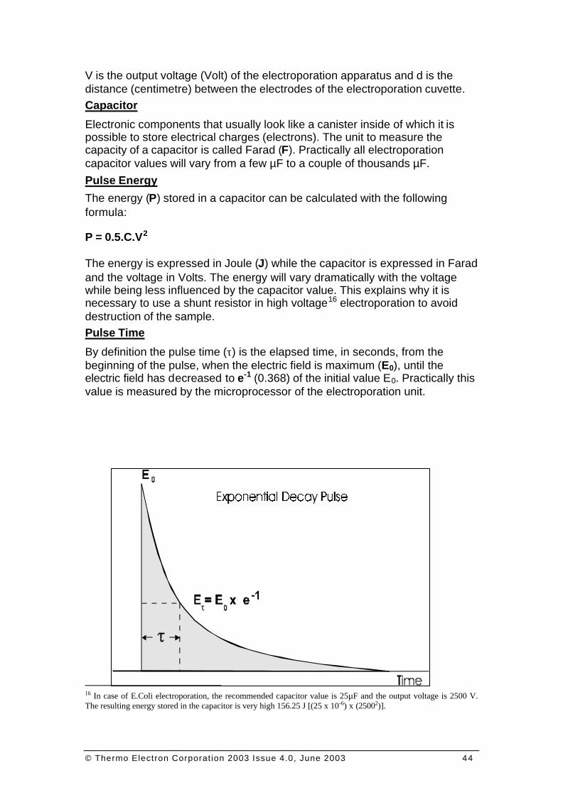
By definition the pulse time (τ) is the elapsed time, in seconds, from the beginning of the pulse, when the electric field is maximum (E0), until the electric field has decreased to e-1 (0.368) of the initial value E0. Practically this value is measured by the microprocessor of the electroporation unit.
16 In case of E.Coli electroporation, the recommended capacitor value is 25µF and the output voltage is 2500 V. The resulting energy stored in the capacitor is very high 156.25 J [(25 x 10-6) x (25002)].
© Thermo Electron Corporation 2003 Issue 4.0, June 2003 45
FI G U R E 07: EXPON ENTIAL DECAY PULSE ; PULSE T IME
The pulse time can be calculated for an ideal system using the following formula:
τ = R.C
Pulse time17 (τ) is expressed in seconds (s) when the resistance value is expressed in Ohms (Ω or R) and the capacitance value in Farad.
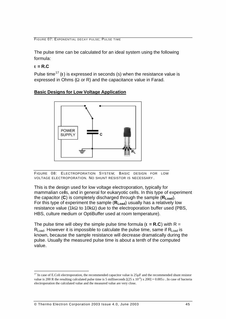
Basic Designs for Low Voltage Application
F IGURE 08: ELECTROPORATION SYSTEM; BASIC DESIGN FOR LOW VOLTAGE ELECTROPORATION. NO SHUNT RESISTOR IS NECESSARY .
This is the design used for low voltage electroporation, typically for mammalian cells, and in general for eukaryotic cells. In this type of experiment the capacitor (C) is completely discharged through the sample (RLoad). For this type of experiment the sample (RLoad) usually has a relatively low resistance value (1kΩ to 10kΩ) due to the electroporation buffer used (PBS, HBS, culture medium or OptiBuffer used at room temperature). The pulse time will obey the simple pulse time formula (τ = R.C) with R = RLoad. However it is impossible to calculate the pulse time, same if RLoad is known, because the sample resistance will decrease dramatically during the pulse. Usually the measured pulse time is about a tenth of the computed value.
17 In case of E.Coli electroporation, the recommended capacitor value is 25µF and the recommended shunt resistor value is 200 R the resulting calculated pulse time is 5 milliseconds [(25 x 10-6) x 200] = 0.005s.In case of bacteria electroporation the calculated value and the measured value are very close.
© Thermo Electron Corporation 2003 Issue 4.0, June 2003 46
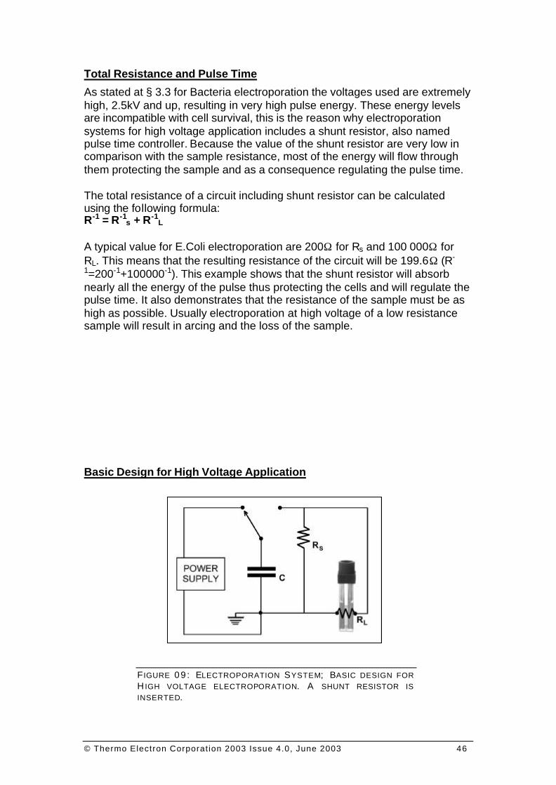
Total Resistance and Pulse Time
As stated at § 3.3 for Bacteria electroporation the voltages used are extremely high, 2.5kV and up, resulting in very high pulse energy. These energy levels are incompatible with cell survival, this is the reason why electroporation systems for high voltage application includes a shunt resistor, also named pulse time controller. Because the value of the shunt resistor are very low in comparison with the sample resistance, most of the energy will flow through them protecting the sample and as a consequence regulating the pulse time. The total resistance of a circuit including shunt resistor can be calculated using the following formula: R-1 = R-1
s + R-1L
A typical value for E.Coli electroporation are 200Ω for Rs and 100 000Ω for RL. This means that the resulting resistance of the circuit will be 199.6Ω (R-
1=200-1+100000-1). This example shows that the shunt resistor will absorb nearly all the energy of the pulse thus protecting the cells and will regulate the pulse time. It also demonstrates that the resistance of the sample must be as high as possible. Usually electroporation at high voltage of a low resistance sample will result in arcing and the loss of the sample.
Basic Design for High Voltage Application
F IGURE 0 9 : ELECTROPORATION SYSTEM; BASIC DESIGN FOR H IGH VOLTAGE ELECTROPORATION. A SHUNT RESISTOR IS INSERTED.
© Thermo Electron Corporation 2003 Issue 4.0, June 2003 47
This is the design used for high voltage electroporation, typically for Bacteria cells, and in general for prokaryotic cell. In this type of experiment the capacitor (C) is discharged through the sample (RL) and a shunt resistor (Rs). For this type of experiment the sample (RL) usually has a very high resistance value (> 50kΩ) due to the electroporation buffer used (usually 18 MΩ water at ice temperature).
THERMO ELECTRON ELECTROPORATION
OPTIMISATION GUIDE
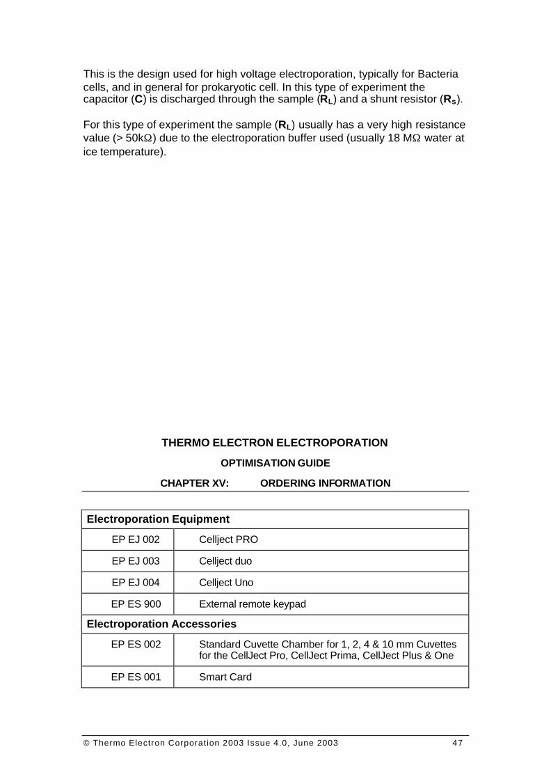
CHAPTER XV: ORDERING INFORMATION
Electroporation Equipment
EP EJ 002 Cellject PRO
EP EJ 003 Cellject duo
EP EJ 004 Cellject Uno
EP ES 900 External remote keypad
Electroporation Accessories
EP ES 002 Standard Cuvette Chamber for 1, 2, 4 & 10 mm Cuvettes for the CellJect Pro, CellJect Prima, CellJect Plus & One
EP ES 001 Smart Card
© Thermo Electron Corporation 2003 Issue 4.0, June 2003 48
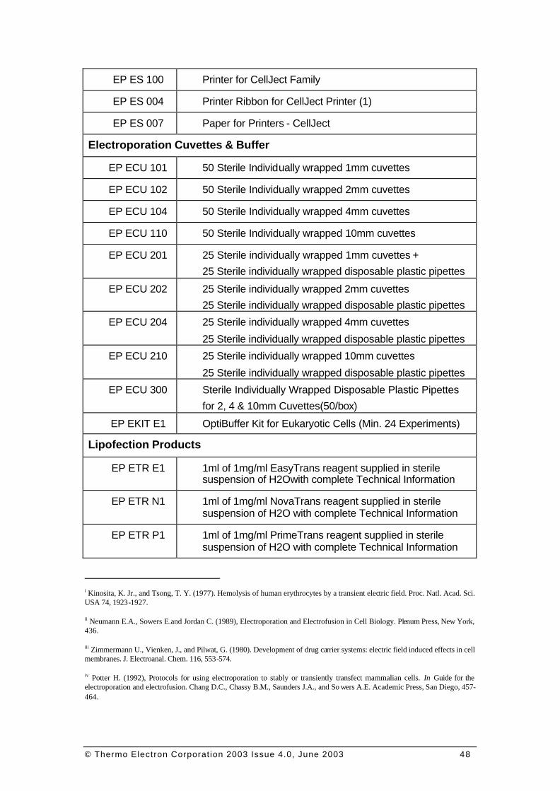
EP ES 100 Printer for CellJect Family
EP ES 004 Printer Ribbon for CellJect Printer (1)
EP ES 007 Paper for Printers - CellJect
Electroporation Cuvettes & Buffer
EP ECU 101 50 Sterile Individually wrapped 1mm cuvettes
EP ECU 102 50 Sterile Individually wrapped 2mm cuvettes
EP ECU 104 50 Sterile Individually wrapped 4mm cuvettes
EP ECU 110 50 Sterile Individually wrapped 10mm cuvettes
EP ECU 201 25 Sterile individually wrapped 1mm cuvettes +
25 Sterile individually wrapped disposable plastic pipettes
EP ECU 202 25 Sterile individually wrapped 2mm cuvettes
25 Sterile individually wrapped disposable plastic pipettes
EP ECU 204 25 Sterile individually wrapped 4mm cuvettes
25 Sterile individually wrapped disposable plastic pipettes
EP ECU 210 25 Sterile individually wrapped 10mm cuvettes
25 Sterile individually wrapped disposable plastic pipettes
EP ECU 300 Sterile Individually Wrapped Disposable Plastic Pipettes
for 2, 4 & 10mm Cuvettes(50/box)
EP EKIT E1 OptiBuffer Kit for Eukaryotic Cells (Min. 24 Experiments)
Lipofection Products
EP ETR E1 1ml of 1mg/ml EasyTrans reagent supplied in sterile suspension of H2Owith complete Technical Information
EP ETR N1 1ml of 1mg/ml NovaTrans reagent supplied in sterile suspension of H2O with complete Technical Information
EP ETR P1 1ml of 1mg/ml PrimeTrans reagent supplied in sterile suspension of H2O with complete Technical Information
i Kinosita, K. Jr., and Tsong, T. Y. (1977). Hemolysis of human erythrocytes by a transient electric field. Proc. Natl. Acad. Sci. USA 74, 1923-1927.
ii Neumann E.A., Sowers E.and Jordan C. (1989), Electroporation and Electrofusion in Cell Biology. Plenum Press, New York, 436.
iii Zimmermann U., Vienken, J., and Pilwat, G. (1980). Development of drug carrier systems: electric field induced effects in cell membranes. J. Electroanal. Chem. 116, 553-574.
iv Potter H. (1992), Protocols for using electroporation to stably or transiently transfect mammalian cells. In Guide for the electroporation and electrofusion. Chang D.C., Chassy B.M., Saunders J.A., and So wers A.E. Academic Press, San Diego, 457-464.
© Thermo Electron Corporation 2003 Issue 4.0, June 2003 49
v Sukharev S.I., Klenchin V.A., Serov S.M., Chernomordik L.V., Chizmadzhev Yu A. (1992), Electroporation and electrophoretic DNA transfer into cells. The effect of DNA interaction with electropores. Biophys J 63 (5), 1320-1327.
vi Tien-An Yang, William C. Heiser and John M. Sedivy (1995), Efficient InSitu electroporation of mammalian cells grown on microporous membranes. Nucleic Acids Research, 23 (15), 2803-2810.
vii Hendrick Wolf, Marie Pierre Rols, Elvira Boldt, Eberhard Neumann and Justin Teissié (1994), Control by Pulse Parameters of Electric Field-Mediated gene Transfer in mammalian cells. Biophysical Journal, 66, 524-531.
viii Christopher Baum, Peter Forster, Susanna Hegewisch-Becker and Klaus Harbers (1994), An Optimized Electroporation Protocol Applicable to a Wide Range of Cell Lines. BioTechniques, 17 (6), 1058-1062.
ix J.M. Teare, R. Islam, R. Flanagan, S. Gallagher, M.G. Davies and C. Grabau (June 1997) Biotechniques 22 (6), 1170-1174.
x William W. Wilfinger, Karol Mackey and Piotr Chomczynski (March 1997), BioTechniques, 22 (3), 474-481.
xi The CelljecT from Thermo Hybaid, launched 1990, was replaced by the CelljecT Pro in 1992.