Embed Size (px)
Citation preview
Electrospinning of Nanofibre Yarns using Rotating
Ring Collector
By
Muhammad Nadeem Shuakat
(B.Sc. Textile Engineering,
MS Fibre & Polymer Engineering)
Submitted in fulfilment of the requirements for the degree of
Doctor of Philosophy
Deakin University
(August, 2014)
DEAKIN UNIVERSITY ACCESS TO THESIS - A
I am the author of the thesis entitled
Electrospinning of Nanofibre Yarns using Rotating Ring Collector
Submitted for the degree of
This thesis may be made available for consultation, loan and limited copying in accordance with the Copyright Act 1968.
'I certify that I am the student named below and that the information provided in the
form is correct' Full Name: Muhammad Nadeem Shuakat Signed: ................................. .………………………………………………..
Date: 20 August 2014
DEAKIN UNIVERSITY
CANDIDATE DECLARATIONI certify the following about the thesis entitled
“Electrospinning of Nanofibre Yarns Using Rotating Ring
Collector.”
Submitted for the degree of
Doctor of Philosophy
a. I am the creator of all or part of the whole work(s) (including content and layout) and that where reference is made to the work of others, due acknowledgment is given.
b. The work(s) are not in any way a violation or infringement of any copyright, trademark, patent, or other rights whatsoever of any person.
c. That if the work(s) have been commissioned, sponsored or supported by any organisation, I have fulfilled all of the obligations required by such contract or agreement.
I also certify that any material in the thesis which has been accepted for a degree or diploma by
any university or institution is identified in the text.
I certify that I am the student named below and that the information provided in the form is
correct'
Full Name................Muhammad Nadeem Shuakat............................
Signed ......................................................…...................……………
Date..........................20 August 2014...................................…………
Dedications
First and foremost, I thank and dedicate this thesis to my God, my Lord,
The Most Merciful, The Most Kind,
Almighty “ALLAH”
For all the blessings and kindness upon me, (which I knew or not), for giving me inner
strength and strong faith in HIM, to complete this thesis (may HE accept it).
Secondly I would humbly dedicate this work to my parents (Shuakat Ali & Akbari
bibi) who strongly opposed my decision to purse my Ph.D. studies, but later, kindly
consented to fulfil my dream. You are the best parents, you are illiterate but still have
light of knowledge, God bless you, here and hereafter. I am also grateful to the rest of
my family who believed in me and supported on every step in my life with their moral
and monetary encouragement.
Here, I also wish to specially thank to my best friend in Pakistan, Mr. Akram Badshah
Butt, for his time to time emotional and moral support.
Especially I dedicate this thesis to my little angels, my daughters
(Habiba, Haiqa &Yusra)
They suffered the most while I was away and could not be with them during the
festivals where every child had their dad with them. I really value your tears which
you shed in the absence of Daddy. Sorry and thanks for being so good and so loving.
Finally I will dedicate my work to my lovely wife, Gulnaz & her family. She and her
family shared all the bad and good times with me. She is blessing from Allah. She was
brought a smile when I was sad and down, keeping me up and doing my thesis. She
taught me the true meanings of love and sacrifice.
Love you Gul, until I die even after that.
Acknowledgments I am indebted to a number of people who kept me motivated, sane, up and doing my
tasks in the shady and dark times of my Ph.D. I would thank Deakin University,
for giving me the opportunity to pursue my Ph.D., by providing me with a DUPRS
(Deakin University Postgraduate Research Scholarship).
First and foremost, I am thankful to Professor Tong Lin and Professor Xungai
Wang. It is both an honour and pleasure working with you, in completing my .Ph.D.
Professor Wang has been kind enough to give me free hand to work on a topic of
my choice. He has always been keen and eager to listen to my ideas and let me work
on them. Prof. Lin’s continuous support and extra ordinary patience led me to
complete this thesis. He was continuously demanding and challenging to get the
impossible job done. His advice and encouragement has been a valuable asset to me.
He has broadened my knowledge and skills in the field of nanotechnology and
nanofibres. In short, both of my supervisors have been excellent and kind in bringing
the best out of me. Thank you Xungai and Tong for your trust and belief in me.
I would thank Mr. Usman Ali for his help in building the electrospinning setup, Dr.
Jian Fang for his assistance with the Scanning Electron Microscopy analysis, Dr.
Haitao Niu and Mr. Badar Munir Zaidi for their assistance in modelling work. I
especially thank Mr. Alex Orokity, Rob Lovett and Graeme Keating for their
technical support in the design and modification of the yarn electrospinning setup.
Without their support, I would not have been able to develop this setup.
I would also wish to thank all the friends and colleagues in Australian Future Fibres
Research & Innovation Centre (AFFRIC) and Institute for Frontier Materials (IFM)
at Deakin University, for their upkeep and inspiration during my stay here. I enjoyed
the smiling and thanking culture in Australia, which introduced me to the new facet
of life. I loved being here, this is such a wonderful continent.
Finally, I would again express my gratitude to my lovely parents, brothers, sister,
daughters and devoted wife for supporting me every step of my student life.
Abstract
Nanofibres possess remarkable properties. A variety of techniques can produce
nanofibres but electrospinning stands distinct in terms of its simplicity and versatility.
Electrospun nanofibres have gained enormous attention over recent decades. Electrospun
nanofibres are predominantly produced in the form of randomly oriented web, which is
fragile and difficult to tailor into 3D complex structures. It is anticipated that the nanofibre
yarns have improved mechanical properties and can be easily converted into fibrous
structures. A few electrospinning setups have been reported to produce nanofibre yarns,
such as electrospinning over a liquid bath, solid collector plate, or on funnel type
collectors. In these setups, typically they electrospin and twist nanofibres in one place.
As a result, pile up on already twisted yarn on winder often occurs, which results in
beaded, fused or hooked nanofibres. It is a challenge to produce nanofibre yarns without
hooked nanofibres.
In this PhD project, a novel ring collector was used to convert newly electrospun
nanofibres into a yarn. This setup has been designed to separate electrospinning from yarn
drafting/twisting in two distinct zones. Three different types of electrospinning systems,
i.e. needle based, needleless, and needle/needleless hybrid, were employed to produce
nanofibres. Their effect on the nanofibre generation and morphology was examined.
Capability of these generators to produce stable inverted nanofibrous cone and continuous
nanofibre yarn from this cone was also investigated. The effect of processing parameters
such as electrospinning setup, voltage and distance on nanofibre generation, their
morphology, cone development, cone stability, yarn fabrication and continuity were also
studied.
Conjugated dual-needle and needle/needleless hybrid systems demonstrated their
ability to produce nanofibre yarns. Yarns with controllable diameters and twists levels
could be produced. The hybrid system could produce yarn at much higher rates than the
needle based system. The mechanical properties of electrospun nanofibre yarns from
these setups were also assessed. Nanofibre yarns showed improved mechanical properties
when compared to randomly-orientated and aligned nanofibre webs.
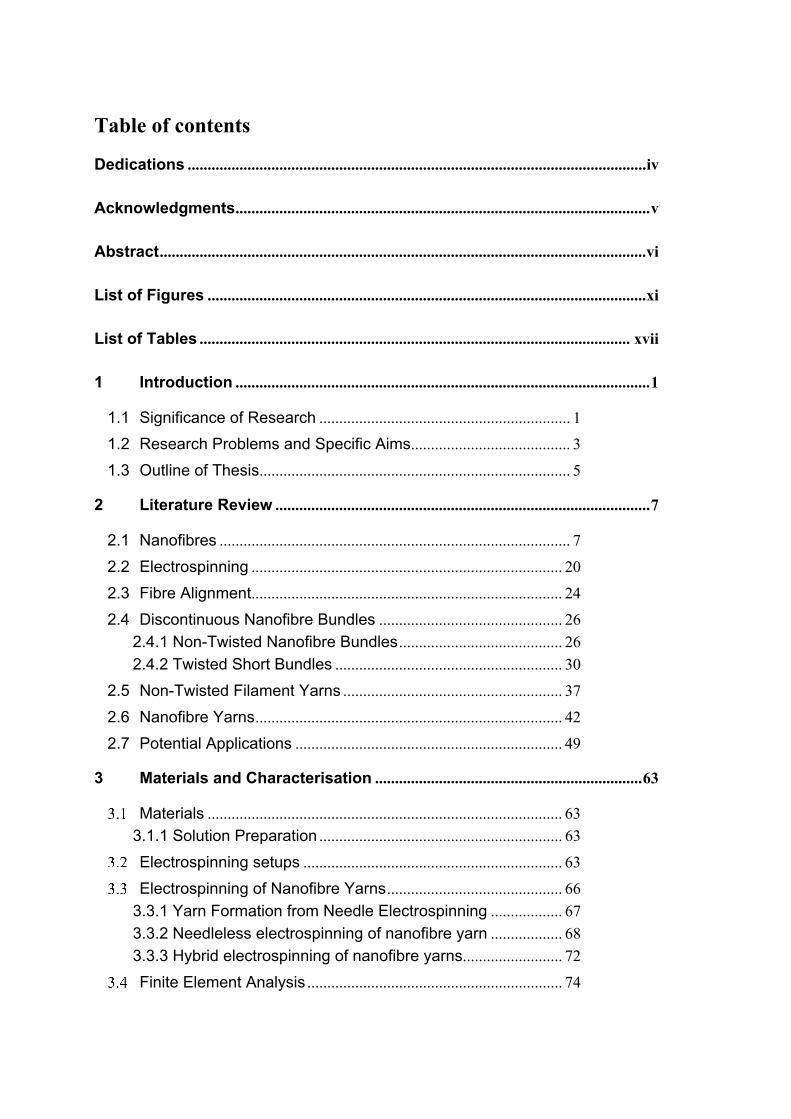
Table of contents
Dedications ................................................................................................................... iv
Acknowledgments ........................................................................................................ v
Abstract .......................................................................................................................... vi
List of Figures .............................................................................................................. xi
List of Tables ............................................................................................................ xvii
1 Introduction ........................................................................................................ 1
1.1 Significance of Research ............................................................... 1
1.2 Research Problems and Specific Aims ........................................ 3
1.3 Outline of Thesis.............................................................................. 5
2 Literature Review .............................................................................................. 7
2.1 Nanofibres ........................................................................................ 7
2.2 Electrospinning .............................................................................. 20
2.3 Fibre Alignment.............................................................................. 24
2.4 Discontinuous Nanofibre Bundles .............................................. 26 2.4.1 Non-Twisted Nanofibre Bundles ......................................... 26 2.4.2 Twisted Short Bundles ......................................................... 30
2.5 Non-Twisted Filament Yarns ....................................................... 37
2.6 Nanofibre Yarns ............................................................................. 42
2.7 Potential Applications ................................................................... 49
3 Materials and Characterisation ................................................................... 63
Materials ......................................................................................... 63 3.1.1 Solution Preparation ............................................................. 63
Electrospinning setups ................................................................. 63
Electrospinning of Nanofibre Yarns ............................................ 66 3.3.1 Yarn Formation from Needle Electrospinning .................. 67 3.3.2 Needleless electrospinning of nanofibre yarn .................. 68 3.3.3 Hybrid electrospinning of nanofibre yarns ......................... 72
Finite Element Analysis ................................................................ 74
Characterisations ........................................................................... 75 3.5.1 Scanning Electron Microscopy (SEM) ................................ 75 3.5.2 Mechanical Properties of Nanofibre Yarns ........................ 76
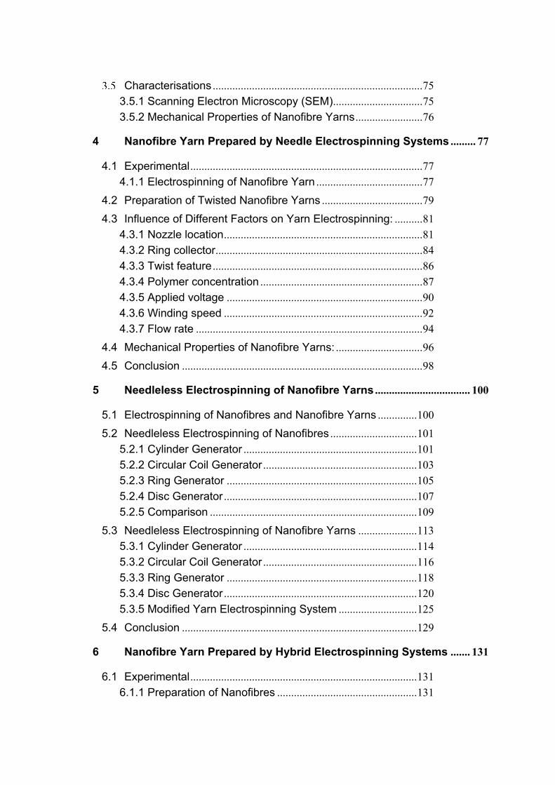
4 Nanofibre Yarn Prepared by Needle Electrospinning Systems ......... 77
4.1 Experimental ................................................................................... 77 4.1.1 Electrospinning of Nanofibre Yarn ...................................... 77
4.2 Preparation of Twisted Nanofibre Yarns .................................... 79
4.3 Influence of Different Factors on Yarn Electrospinning: .......... 81 4.3.1 Nozzle location ....................................................................... 81 4.3.2 Ring collector .......................................................................... 84 4.3.3 Twist feature ........................................................................... 86 4.3.4 Polymer concentration .......................................................... 87 4.3.5 Applied voltage ...................................................................... 90 4.3.6 Winding speed ....................................................................... 92 4.3.7 Flow rate ................................................................................. 94
4.4 Mechanical Properties of Nanofibre Yarns: ............................... 96
4.5 Conclusion ...................................................................................... 98
5 Needleless Electrospinning of Nanofibre Yarns .................................. 100
5.1 Electrospinning of Nanofibres and Nanofibre Yarns .............. 100
5.2 Needleless Electrospinning of Nanofibres ............................... 101 5.2.1 Cylinder Generator .............................................................. 101 5.2.2 Circular Coil Generator ....................................................... 103 5.2.3 Ring Generator .................................................................... 105 5.2.4 Disc Generator ..................................................................... 107 5.2.5 Comparison .......................................................................... 109
5.3 Needleless Electrospinning of Nanofibre Yarns ..................... 113 5.3.1 Cylinder Generator .............................................................. 114 5.3.2 Circular Coil Generator .......................................................1165.3.3 Ring Generator .................................................................... 118 5.3.4 Disc Generator ..................................................................... 120 5.3.5 Modified Yarn Electrospinning System ............................ 125
5.4 Conclusion .................................................................................... 129
6 Nanofibre Yarn Prepared by Hybrid Electrospinning Systems ....... 131
6.1 Experimental ................................................................................. 131 6.1.1 Preparation of Nanofibres .................................................. 131
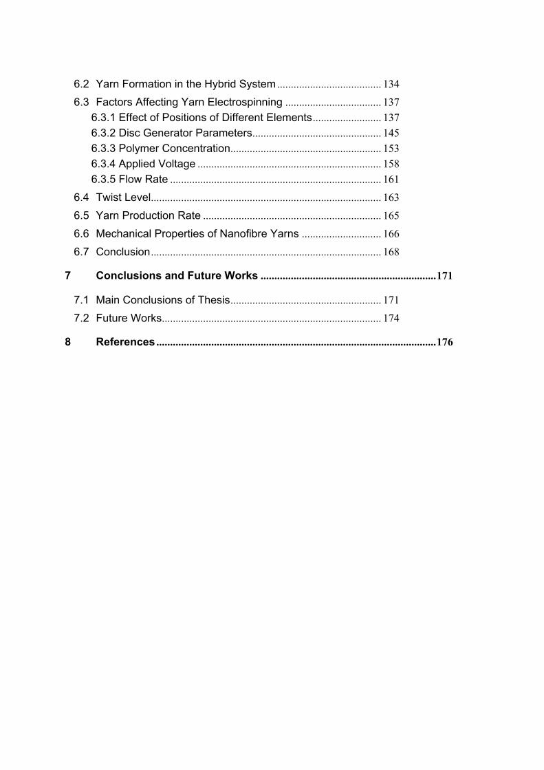
6.2 Yarn Formation in the Hybrid System ...................................... 134
6.3 Factors Affecting Yarn Electrospinning ................................... 137 6.3.1 Effect of Positions of Different Elements ......................... 137 6.3.2 Disc Generator Parameters ............................................... 145 6.3.3 Polymer Concentration ....................................................... 153 6.3.4 Applied Voltage ................................................................... 158 6.3.5 Flow Rate ............................................................................. 161
6.4 Twist Level .................................................................................... 163
6.5 Yarn Production Rate ................................................................. 165
6.6 Mechanical Properties of Nanofibre Yarns ............................. 166
6.7 Conclusion .................................................................................... 168
7 Conclusions and Future Works ................................................................ 171
7.1 Main Conclusions of Thesis ....................................................... 171
7.2 Future Works ................................................................................ 174
8 References ...................................................................................................... 176
List of Figures
Figure 2.1 Present and future trend of global nanofibre consumption. ................. 8
Figure 2.2 Classification of nanofibre bundles. ....................................................... 11
Figure 2.3 (a) Setup for generating polymer spikes from a solution on a ferro-
magneto fluid [196], (b) Nanofibre generator of the Nanospider® (c) Bubble
electrospinning, [198] and (d) Needleless conical wire coil generator [199]. ..... 21
Figure 2.4 Needleless generators and their electric field profiles (a) and (d) disc
generator, (b) and (e) cylinder generator, and (c) and (f) circular coil generator
[207]. .............................................................................................................................. 23
Figure 2.5 Fibre alignment using (a) high speed rotating collector [212], (b) sharp
edge collector [214], (c) frame electrode [215] and (d) parallel electrode [216]. 24
Figure 2.6 Intensified electric field using (a) sharp needle encompassed in a drum
cylinder [213], (b) parallel sharp edge plates [217] and (c) sharp edge needle
placed at an angle [217]. ............................................................................................. 25
Figure 2.7 Photograph showing short nanofibre bundles over sharp blade edges
[217]. .............................................................................................................................. 27
Figure 2.8 Schematic of short nanofibre bundles over a rotary fin collector [228].
........................................................................................................................................ 29
Figure 2.9 (a) SEM image of short PVDF-HFP nanofibre bundle prepared by
twisting a nanofibre strip, (b) & (c) effect of twist on (b) bundle strength and (c)
bundle diameter[232] . ................................................................................................. 32
Figure 2.10 (a) Schematic for twist insertion and (b) SEM images of twisted
nanofibre bundle [218]. ............................................................................................... 33
Figure 2.11 Twisted single PEO nanofibre produced by auxiliary electrode. [40].
........................................................................................................................................ 34
Figure 2.12 (a) Schematic diagram for producing short nanofibre bundles[41], (b)
hollow hemi-sphere and sharp rod setup for nanofibre bundle collection, and (c)
SEM image of collected semi conducting metal oxide nanofibre bundle [236]. . 35
Figure 2.13 (a) Schematic setup consisting two needle nozzle generators over a
sharp needle collector for micro-rope manufacturing. (b) SEM image of twisted
micro-ropes [39]. ........................................................................................................... 36
Figure 2.14 Photograph of continuous non-twisted PLA/PAN and SWCNTs
filament yarn [42] .......................................................................................................... 38
Figure 2.15 (a) Schematic for conjugated needle and roller system. (b) SEM
image of non-twisted nanofibre filament yarn [44]. ................................................. 38
Figure 2.16 (a) Schematic of self-bundling by needle. (b) PAN nanofibre filament
yarn using organic salt [238]. ...................................................................................... 39
Figure 2.17 Non-twisted filament yarn from (a) single nozzle and circular disc
[242], multiple nozzles electro-spinning over, (b) disc and (c) conveyer belt. .... 40
Figure 2.18 (a) Schematic for collecting continuous nanofibre filament on liquid
bath [243], (b) SEM image of nanofibre filament yarn [244]. ................................. 41
Figure 2.19 (a) Schematic of bar manipulated electric field. (b) SEM image of
PAN nanofibre yarn [246]. ........................................................................................... 42
Figure 2.20 (a) Schematic double disc setup for simultaneously twist insertion
and winding. (b) SEM image of twisted nanofibre yarn [248]. ............................... 43
Figure 2.21 (a) Schematic of liquid vortex, (b) resultant twisted nanofibre yarn.
[251]. ............................................................................................................................... 45
Figure 2.22 (a) Schematic diagram of twisted nanofibre yarn developed by
vertical funnel and single needle generator, (b) SEM image of twisted nanofibre
yarn. [46] ........................................................................................................................ 46
Figure 2.23 Effect of funnel rotation speed on yarn twist level of nanofibre yarns.
......................................................................................................................................... 47
Figure 2.24 (a) Schematic diagram of horizontal funnel and double needle
generators. (b) Highly twisted PAN nanofibre yarn [47]. ........................................ 47
Figure 2.25 Photograph showing change of fibrous cone shape using tube with
(a) large diameter and (b) small diameter [252]. ..................................................... 48
Figure 2.26 (a) Continuous twistless PLLA-Zein/Zein nanofibre filament yarn [45],
(b) schematic of tapered and twisted yarn. (c) twisted NiO/ZnO nanofibre yarn.
[236, 237]. ...................................................................................................................... 49
Figure 2.27 (a) Biscrolled nanofibre single nanofibre yarn, plied nanofibre yarn
and nanofibre braided structure. (b) Solid state supercapacitor woven into glove.
[255] ................................................................................................................................ 51
Figure 2.28 (a) A paddle attached to biscrolled yarn to visualize torque in the
nanofibre yarn. (b) Niobium twisted yarn [257]. ...................................................... 52
Figure 2.29 (a) Woven PCL fabric [243], (b) Zein/PLLA composite nanofibre
yarns based plain weave fabric [45], (c) double layer plain weave composite fabric
of PAN (upper layer) and PVDF-HFP (bottom layer) nanofibre yarn. (d) single
jersey knitted fabric using PVD F-HFP nanofibre yarn and polypropylene
multifilament 251. ............................................................................................................ 54
Figure 3.1 Schematic for basic needle based electrospinning setup. ................. 64
Figure 3.2 Schematic for needleless generator based electrospinning setup. .. 65
Figure 3.3 Schematic illustration of needle based nanofibre yarn electrospinning
setup. .............................................................................................................................. 67
Figure 3.4 Needleless electrospinning setups for preparation of nanofibre yarns
(a) cylinder generator (b) circular coil generator (c) ring generator and (d) disc
generator. ...................................................................................................................... 69
Figure 3.5 Yarn electrospinning setup with an auxiliary electrode. ...................... 70
Figure 3.6 Yarn electrospinning setup with air jet enhancement. ........................ 71
Figure 3.7 Hybrid electrospinning setup for nanofibre yarn fabrication. .............. 73
Figure 3.8 Photograph of Neoscope JCM 5000 bench top SEM machine. ........ 75
Figure 3.9 Photograph of FAVIMAT with Robot 2 creel, showing pneumatic jaws
in magnified view. ......................................................................................................... 76
Figure 4.1 a) Schematic illustration of yarn electrospinning setup, b) photograph
of fibrous cone formed on ring collector, and c) inset shows nanofibre yarn
collected on a spool. .................................................................................................... 79
Figure 4.2 Schematic showing details of nozzle placement. ................................. 82
Figure 4.3 Effect of ring collector speed on a) fibre and yarn diameters, b) twist
level features. ................................................................................................................ 85
Figure 4.4 Effect of polymer concentration on nanofibre and yarn diameter
(Applied voltage = 13 kV, Ring collector speed 1200 rpm; total volume flow rate
3.0 ml/h, flow rate ratio for positive/negative nozzles 2.1:0.9). ............................. 87
Figure 4.5 Effect of Voltage on nanofibre and yarn diameter (polymer
concentration 17.0 %, ring collector speed 1200 rpm; total volume flow rate 3.0
ml/h, flow rate ratio for positive/negative nozzles 2.1:0.9). .................................... 91
Figure 4.6 Effect of winder speed on nanofibre and yarn diameter, (polymer
concentration 17.0 %, 13kV applied voltage , Ring collector speed 1200 rpm; total
volume flow rate 3.0 ml/h, flow rate ratio for positive/negative nozzles 2.1:0.9).
......................................................................................................................................... 93
Figure 4.7 Effect of flow rate on nanofibre and yarn diameter, (polymer
concentration 17.0 %, applied voltage = 13kV, Ring collector speed 1200 rpm;
flow rate ratio for positive/negative nozzles 2.1:0.9). .............................................. 95
Figure 4.8 a) Typical stress ~ strain curves of randomly-orientated nanofibre web,
aligned nanofibre web and nanofibre yarn and b) effect of twist level on stress
and strain of typical nanofibre yarns. ......................................................................... 97
Figure 5.1 SEM images of nanofibres produced from cylinder generator at
different magnification levels. ................................................................................... 102
Figure 5.2 SEM images of nanofibres produced using circular coil as fibre
generator. ..................................................................................................................... 104
Figure 5.3 SEM images for nanofibres generated by ring generator at different
magnification levels. ................................................................................................... 106
Figure 5.4 SEM images for nanofibres produced by disc generator. ............................ 108
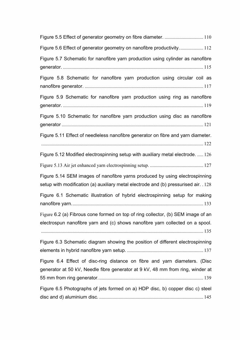
Figure 5.5 Effect of generator geometry on fibre diameter. ................................ 110
Figure 5.6 Effect of generator geometry on nanofibre productivity. ................... 112
Figure 5.7 Schematic for nanofibre yarn production using cylinder as nanofibre
generator. .................................................................................................................... 115
Figure 5.8 Schematic for nanofibre yarn production using circular coil as
nanofibre generator. .................................................................................................. 117
Figure 5.9 Schematic for nanofibre yarn production using ring as nanofibre
generator. .................................................................................................................... 119
Figure 5.10 Schematic for nanofibre yarn production using disc as nanofibre
generator ..................................................................................................................... 121
Figure 5.11 Effect of needleless nanofibre generator on fibre and yarn diameter.
...................................................................................................................................... 122
Figure 5.12 Modified electrospinning setup with auxiliary metal electrode. ..... 126
Figure 5.13 Air jet enhanced yarn electrospinning setup. ............................................ 127
Figure 5.14 SEM images of nanofibre yarns produced by using electrospinning
setup with modification (a) auxiliary metal electrode and (b) pressurised air. . 128
Figure 6.1 Schematic illustration of hybrid electrospinning setup for making
nanofibre yarn. ............................................................................................................ 133
Figure 6.2 (a) Fibrous cone formed on top of ring collector, (b) SEM image of an
electrospun nanofibre yarn and (c) shows nanofibre yarn collected on a spool.
...................................................................................................................................... 135
Figure 6.3 Schematic diagram showing the position of different electrospinning
elements in hybrid nanofibre yarn setup. ............................................................... 137
Figure 6.4 Effect of disc-ring distance on fibre and yarn diameters. (Disc
generator at 50 kV, Needle fibre generator at 9 kV, 48 mm from ring, winder at
55 mm from ring generator. ...................................................................................... 139
Figure 6.5 Photographs of jets formed on a) HDP disc, b) copper disc c) steel
disc and d) aluminium disc. ...................................................................................... 145
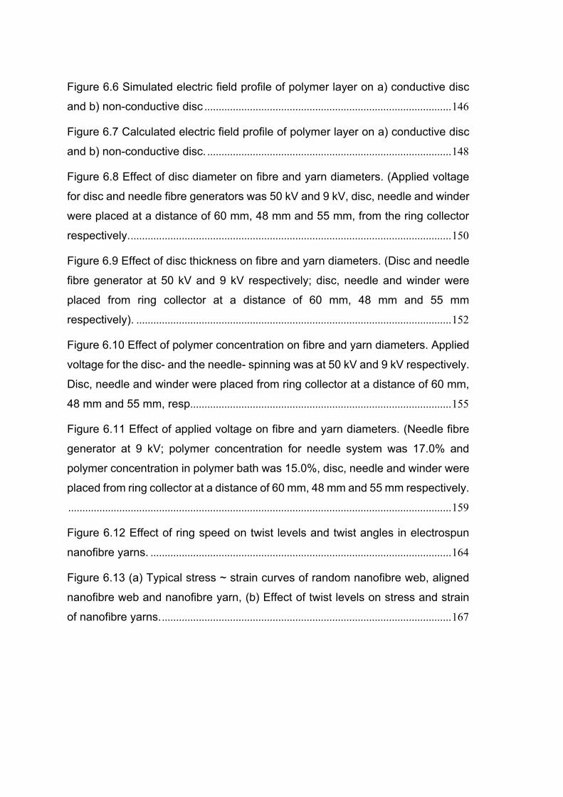
Figure 6.6 Simulated electric field profile of polymer layer on a) conductive disc
and b) non-conductive disc ....................................................................................... 146
Figure 6.7 Calculated electric field profile of polymer layer on a) conductive disc
and b) non-conductive disc. ...................................................................................... 148
Figure 6.8 Effect of disc diameter on fibre and yarn diameters. (Applied voltage
for disc and needle fibre generators was 50 kV and 9 kV, disc, needle and winder
were placed at a distance of 60 mm, 48 mm and 55 mm, from the ring collector
respectively. ................................................................................................................. 150
Figure 6.9 Effect of disc thickness on fibre and yarn diameters. (Disc and needle
fibre generator at 50 kV and 9 kV respectively; disc, needle and winder were
placed from ring collector at a distance of 60 mm, 48 mm and 55 mm
respectively). ............................................................................................................... 152
Figure 6.10 Effect of polymer concentration on fibre and yarn diameters. Applied
voltage for the disc- and the needle- spinning was at 50 kV and 9 kV respectively.
Disc, needle and winder were placed from ring collector at a distance of 60 mm,
48 mm and 55 mm, resp ............................................................................................ 155
Figure 6.11 Effect of applied voltage on fibre and yarn diameters. (Needle fibre
generator at 9 kV; polymer concentration for needle system was 17.0% and
polymer concentration in polymer bath was 15.0%, disc, needle and winder were
placed from ring collector at a distance of 60 mm, 48 mm and 55 mm respectively.
....................................................................................................................................... 159
Figure 6.12 Effect of ring speed on twist levels and twist angles in electrospun
nanofibre yarns. .......................................................................................................... 164
Figure 6.13 (a) Typical stress ~ strain curves of random nanofibre web, aligned
nanofibre web and nanofibre yarn, (b) Effect of twist levels on stress and strain
of nanofibre yarns. ...................................................................................................... 167
List of Tables
Table 2.1 Different nanofibre making techniques ................................................... 12
Table 2.2 Commonly used polymer materials in electrospinning ......................... 13
Table 4.1 Effect of nozzle distances on yarn formation*........................................ 83
Table 4.2 Effect of polymer concentration on yarn electrospinning ..................... 89
Table 5.1 Effect of generator geometry on fibre morphology, cone stability and
yarn formation. ............................................................................................................ 123
Table 6.1 Effect of nanofibre generators and winder position on cone stability and
yarn formation. ............................................................................................................ 141
Table 6.2 Effect of polymer concentration on yarn electrospinning ................... 157

- 1 -
C H A P T E R O N E
1 Introduction
1.1 Significance of Research
Nanofibres have a diameter in the range of nanometres, and possess large
surface to mass ratio. They exhibit superior physiochemical properties to their
micrometre counterparts. The unique characteristics together with the
functionalities from the material itself have offered huge potential for nanofibres
to be used in a number of areas e.g., filters, sensors, drug delivery, biomedical,
protective clothing, catalysis energy generation and storage. Although the
concept of electrospinning was observed a century ago, it has not received any
attention until very recently.
Nanofibres are predominantly produced in the form of randomly oriented
fibrous web, which are fragile and require sophisticated technology to process
them. By converting nanofibres into continuous twisted nanofibre yarns, their
strength improves and they can be easily tailored into complex 3D structures.
These complex 3D structures are anticipated to exhibit novel functionalities. It
is anticipated that the fabrics developed from nanofibre yarns would be softer,
lighter, tougher, flexible and more absorbent than traditional fabrics. Owing to
interconnected pores, these fabrics would possess increased number of
capillaries; helping in better wicking, superior drug release and enhanced
proliferation of cells. Therefore, fabrics produced from nanofibre yarns could be
a good candidate in wound dressings, scaffolds, sanitary products, composite
reinforcement, high efficiency filters and wearable electronics.
Chapter 1: [Introduction and Research Aims]
In some instances, the formation of short twisted nanofibre bundles or
cut strip webs after electrospinning have been reported. Continuous non-twisted
nanofibre yarns have also been produced using non-solvent liquid baths.
Nanofibres were directly deposited on the liquid surface and wound into yarns.
Using vortex at the bath base resulted in twisted nanofibre yarns. Although liquid
bath helped in neutralizing nanofibres, it adversely affected nanofibre
morphology, orientation and ingredients. It was also very difficult to control
twist and uniformity in as-prepared yarns, and only insoluble polymers could be
processed. Direct deposition of nanofibres over solid collectors and twisting
them into nanofibres without utilizing liquid bath is extremely encouraging. The
yarns produced from these setups demonstrated well defined twists and superior
mechanical properties.
Recently, usage of conical funnel or rotary tube as transient collector had
greatly increased yarn production rates. During electrospinning nanofibres were
manually dragged to the winder to form a fibrous cone over collector periphery.
The funnel rotation inserted twists, while cone apex was continuously drafted to
form nanofibre yarn. This setup could produce nanofibre yarns with controllable
fibre/yarn diameters and twist levels. However, the nanofibre generation and
yarn forming were carried out in the same zone, the already twisted yarns was
contaminated with later electrospun nanofibres. Consequently, fused, beaded
and hooked nanofibres were observed, deteriorating yarn quality.
Chapter 1: [Introduction and Research Aims]
1.2 Research Problems and Specific Aims
The electrospinning setups reported so far generate nanofibres and yarn
in the same region. Consequently, the yarns produced from these systems show
beads, fused and hooked nanofibres, which deteriorate fibre morphology,
alignment and overall yarn quality. It is still a challenge to produce nanofibre
yarn without beads, fused or hooked nanofibre structure. Therefore, the overall
objective of this PhD study is to find a new way to electrospin nanofibre yarn. It
is preferable that nanofibre and yarn are formed in two distinct zones, such that
the above mentioned problems are eliminated. The new setup will prevent
beaded, fused or hooked nanofibre formation and exclude these defects in final
nanofibre yarn. Accordingly, the research focuses on three specific aims as
described below:
Specific Aim 1: To develop a novel needle electrospinning setup
capable of electrospin nanofibres and convert nanofibres into a yarn in a
zone beyond fibre generating area; and study the structure-property
relationship.
Needleless electrospinning is anticipated to have higher nanofibre
production rate than needle electrospinning. Although considerable work has
been carried out in nanofibre yarn fabrication, most of nanofibre yarns are
prepared using needle based electrospinning technique. These yarn
electrospinning techniques typically have a low yarn electrospinning rate.
Nanofibre yarns prepared by needleless electrospinning technique is highly
desired to have higher yarn production rate, but needleless yarn electrospinning
Chapter 1: [Introduction and Research Aims]
technique has not been reported in research literature. The second specific aim
of this PhD thesis is:
Specific Aim 2: Production of nanofibre yarn using needleless
electrospinning setup, and elucidating the effect of fibre generator on fibre
and yarn morphology.
As nanofibre yarn manufacturing is still in its early stages, it is not
surprising to note that no nanofibre yarn is prepared from a hybrid system
combining both needle and needleless electrospinning system. It is interesting to
see whether hybrid electrospinning system can be used to produce nanofibre
yarns. This leads to the third specific aim of this research:
Specific Aim 3: To use a combination of needle and needleless
electrospinning systems for nanofibre yarn production, and evaluate effects
of processing parameters on yarn formation.
In short, this project mainly revolves around the development of novel
electrospinning setup for production of nanofibre yarns, and effects of
electrospinning parameters on yarn formation.
Chapter 1: [Introduction and Research Aims]
1.3 Outline of Thesis
Apart from this introduction chapter, this thesis includes further six
chapters as detailed below:
Chapter 2 is a literature review summarizing the recent progress in the
nanofibres, nanofibre-making techniques, polymer materials and their solvents
used for electrospinning, applications of nanofibres, nanofibre alignment,
techniques used for formation of nanofibre bundles and nanofibre yarns, and
potential applications of nanofibre yarns.
Chapter 3 details polymer materials and solvents used in this research,
basic electrospinning for nanofibre production, novel needle, needleless and
hybrid yarn electrospinning setups, and characterisation techniques.
Chapter 4 deals with the development of a novel needle yarn
electrospinning system. Effect of material and processing parameters on
nanofibre morphology, fibrous cone and nanofibre yarn were investigated.
Mechanical properties of nanofibre yarn was also studied and compared with
aligned nanofibre web and nanofibre nonwoven. Effect of twist levels on yarn
tensile property was also examined.
Chapter 5 describes experiment results about needleless electrospinning
using cylinder, circular coil, ring and disc as fibre generator. Nanofibre
production, fibre morphology, fibrous cone formulation and possibility of
nanofibre yarn production using needleless generators was assessed. Effect of
Chapter 1: [Introduction and Research Aims]
auxiliary electrode and compressed air system on quick drying of nanofibres and
yarn fabrications were also evaluated.
Chapter 6 reports the usage of hybrid electrospinning system in
combination of needle and needleless electrospinning to produce nanofibre yarn.
Impact of different processing parameters on nanofibres, cone stability and
continuous yarn assembling was studied. Mechanical properties of nanofibre
yarns and effect of twist levels on yarn tensile properties were also evaluated.
Chapter 7 The chapter sums up the entire work done in this project. This
chapter also proposes future works in this specific area.
- 7 -
C H A P T E R T W O
2 Literature Review
2.1 Nanofibres
Nanofibres also known as superfine fibres have diameter smaller than 1
micron 1 and aspect ratio (length to diameter ratio) at least 100:1 2. Nanofibres
show considerably improved physiochemical properties in comparison to fibres
of greater diameter. They possess high surface-to-mass ratio and excellent pore
inter-connectivity. Nanofibres have shown enormous potential for applications
in areas as diverse as filtration 3, sensor 4, drug delivery 5-7, biomedical 8-11,
protective clothing 12, catalysis 13,14, energy storage 15 and generation 16-18.
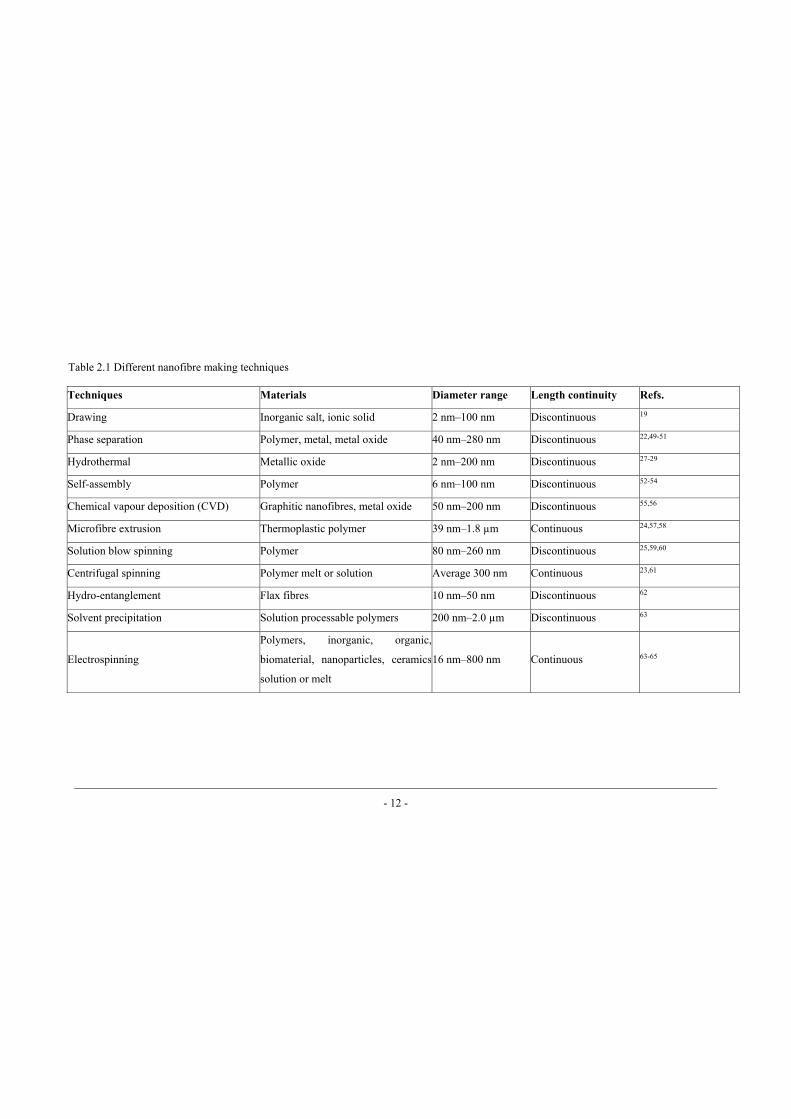
Several techniques have been developed to produce nanofibres, such as drawing
19,20, template-synthesis 21, phase-separation 22, centrifugal-spinning 23, bi-
component extrusion 24, solution blowing 25, chemical vapour deposition 26, and
hydrothermal 27-29. Table 2.1 describes different nanofibre making techniques,
materials and fibre dimensional features.
Electrospinning is a simple but efficient technique to produce nanofibres. This
technique involves drawing a polymer fluid under a strong electric field into fine
filaments, which deposit randomly on the collector to form a nonwoven web in
the most cases. During electrospinning, “Taylor-cone” is developed from the
fluid surface, and jet ejects from Taylor-cone when the electric force is strong
enough to overcome the surface tension of the fluid. The charged jet typically
undergoes a whipping movement due to the intensive interaction with the
Chapter 2: [Literature Review]
external electric field, stretching itself thinner. With this technique, nanofibres
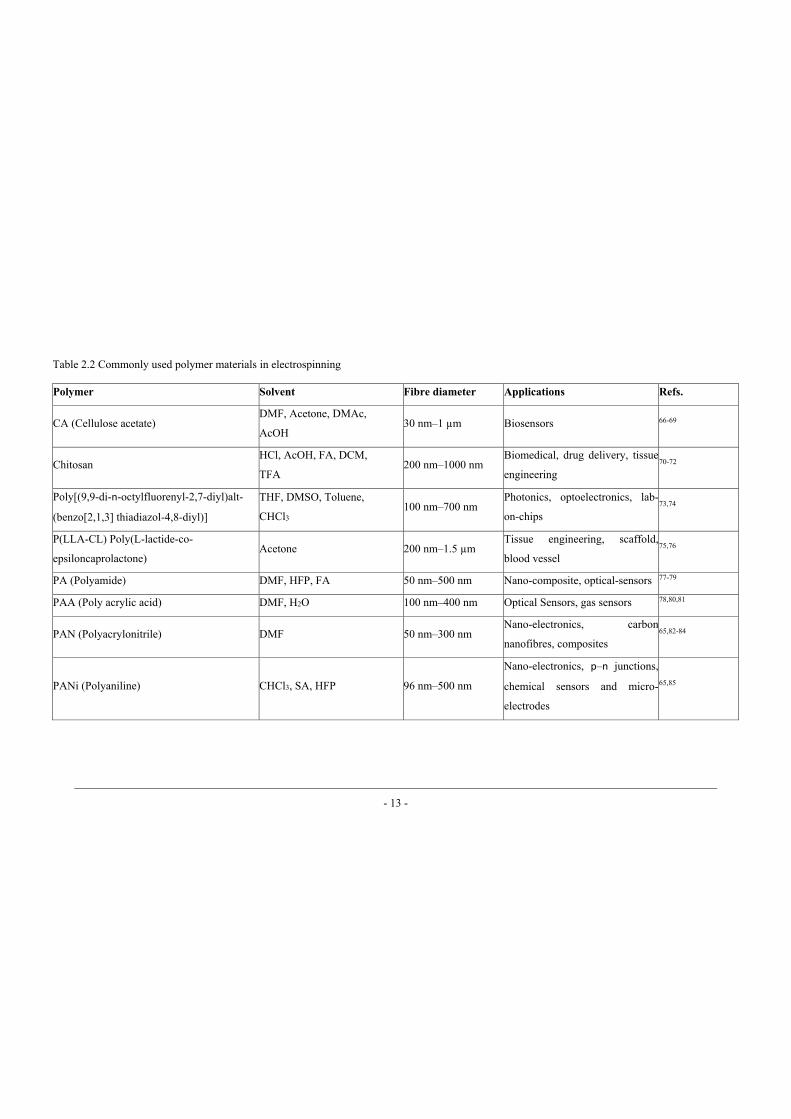
are prepared from a number of polymers. Table 2.2 enlists polymer materials
mainly used for electrospinning of nanofibres.
Electrospinning has become a popular fibre-making technique since
1995, although the concept of drawing liquid with electric force was known as
early as 16th century. Practical success of using electrostatic force to spin a liquid
into fibres was first patented by Formhals et al. 30,31 in 1930s. In the patents, the
formation of yarns from polymer solutions with a motive to replace expensive
silk fibres was also claimed. The invention of nylon (polyamides) and eruption
of World War II subdued electrospinning as it could not compete with the bulk
production of nylon and later polyester.
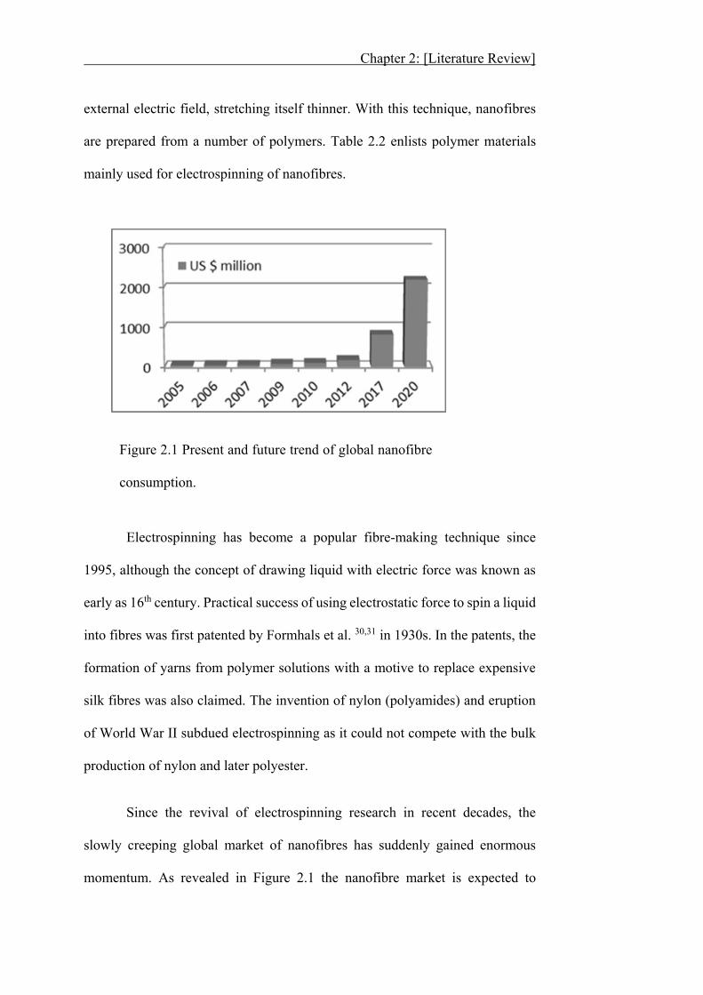
Since the revival of electrospinning research in recent decades, the
slowly creeping global market of nanofibres has suddenly gained enormous
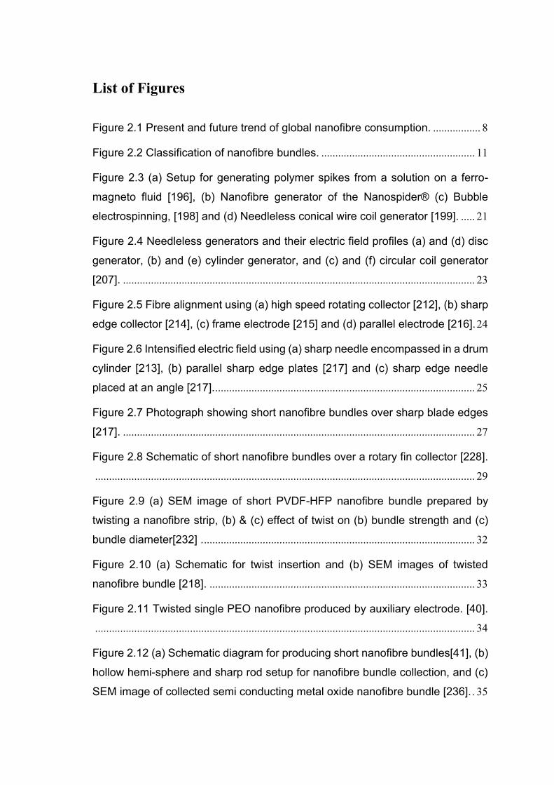
momentum. As revealed in Figure 2.1 the nanofibre market is expected to
Figure 2.1 Present and future trend of global nanofibre
consumption.
Chapter 2: [Literature Review]
increase 1,200% in less than a decade. It was predicted that chemical and
mechanical sectors will utilize 70% of total nanofibre production, while energy
and electronics sectors will encompass a major share of remaining nanofibres 32.
Ever increasing consumption of nanofibres will definitely require scaling
up of nanofibre production. However, low production, frangibility and random
arrangement of nanofibres have been identified as bottle-necks in nanofibre
commercialization. Most of the initial researches in electrospinning were
focused on preparation and characterisation of randomly-oriented nanofibre
webs 33. A recent study conducted on tissue engineering has revealed that cells
show better proliferation on aligned nanofibrous structures 34. In addition,
aligned nanofibre bundles have been demonstrated to have better mechanical
strength than randomly-oriented nanofibre webs35.
The pursuit for enhanced strength and bulk production of nanofibres
encouraged researchers to find new methods to produce aligned nanofibre yarns.
While a lot of papers reported on non-twisted 36-38 or twisted 39-41 nanofibre
bundles and yarns 42-48, not a single study was found covering all the aspects of
nanofibre mass production, alignment and formation of nanofibre bundles/yarns.
In this chapter, two major electrospinning techniques, needle and
needleless electrospinning, and fibre alignment are briefly described. Detailed
accounts on different techniques for producing aligned short fibre bundles (in
either twisted or non-twisted form), continuous filament yarn, and nanofibre
yarns are elaborated. It is expected that this literature review provides overall
understanding of underlying concepts for producing nanofibres on a mass scale,
Chapter 2: [Literature Review]
electrospun nanofibre bundle and yarn formation, and assistance in planning
future research in the field of electrospun nanofibre yarns and their subsequent
structures.
Owing to the enormous application potential, electrospun nanofibres
have attracted wide interests from researchers with diversified backgrounds, in
both textile and non-textile fields. Fibre and yarn terminologies are occasionally
used interchangeably, which create misunderstanding. For example, yarn was
used in some papers to describe fibre filaments, while nanofibre filaments were
used to describe nanofibre yarns in some others. To eliminate this confusion, it
is necessary to clarify these terms.
Filament: A fibre of indefinite length.
Fibre bundle: An assembly of small fibres aligned in a specific direction.
Filament yarn: A long non-twisted array of one or more filaments.
Yarn: A long continuous length of interlocked (twisted) fibres.
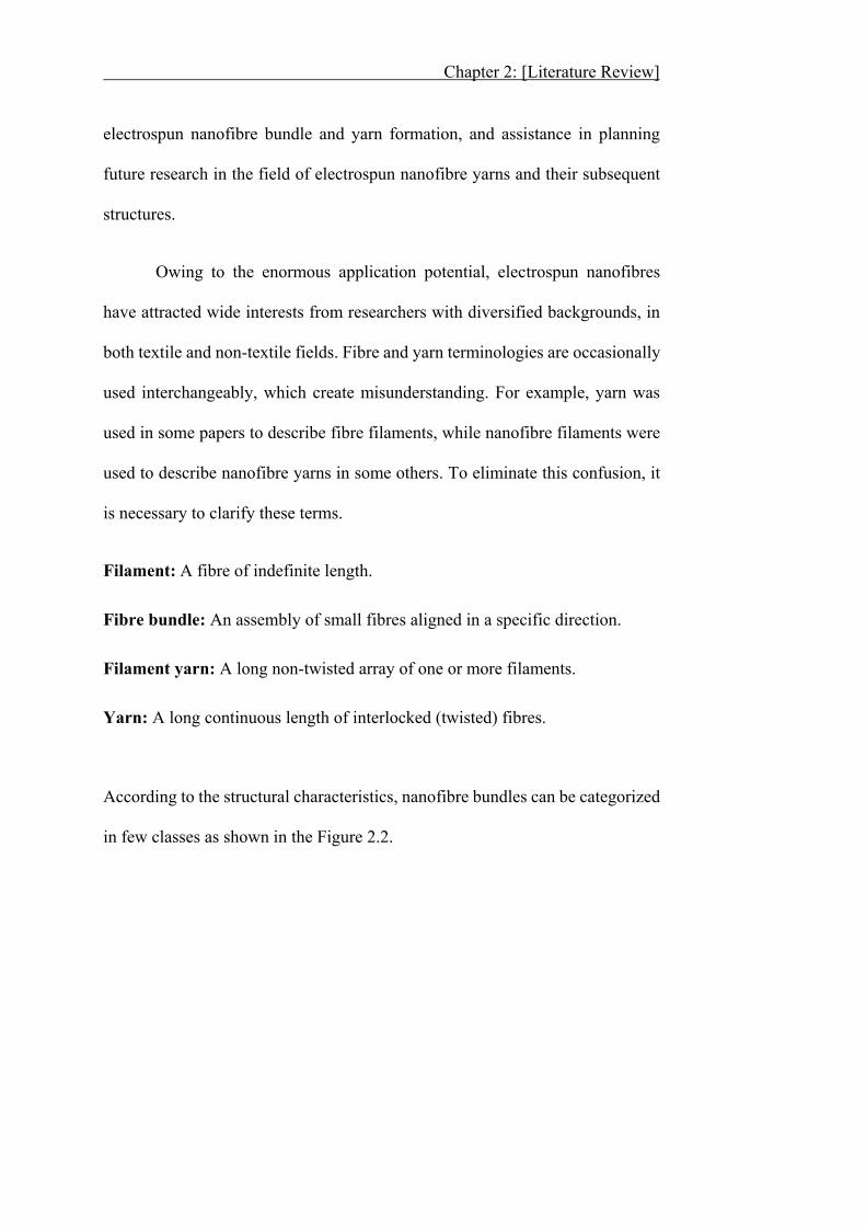
According to the structural characteristics, nanofibre bundles can be categorized
in few classes as shown in the Figure 2.2.
Chapter 2: [Literature Review]
Figure 2.2 Classification of nanofibre bundles.
- 12 -
Techniques Materials Diameter range Length continuity Refs.
Drawing Inorganic salt, ionic solid 2 nm–100 nm Discontinuous 19
Phase separation Polymer, metal, metal oxide 40 nm–280 nm Discontinuous 22,49-51
Hydrothermal Metallic oxide 2 nm–200 nm Discontinuous 27-29
Self-assembly Polymer 6 nm–100 nm Discontinuous 52-54
Chemical vapour deposition (CVD) Graphitic nanofibres, metal oxide 50 nm–200 nm Discontinuous 55,56
Microfibre extrusion Thermoplastic polymer 39 nm–1.8 μm Continuous 24,57,58
Solution blow spinning Polymer 80 nm–260 nm Discontinuous 25,59,60
Centrifugal spinning Polymer melt or solution Average 300 nm Continuous 23,61
Hydro-entanglement Flax fibres 10 nm–50 nm Discontinuous 62
Solvent precipitation Solution processable polymers 200 nm–2.0 μm Discontinuous 63
Electrospinning
Polymers, inorganic, organic,
biomaterial, nanoparticles, ceramics
solution or melt
16 nm–800 nm Continuous 63-65
Table 2.1 Different nanofibre making techniques
- 13 -
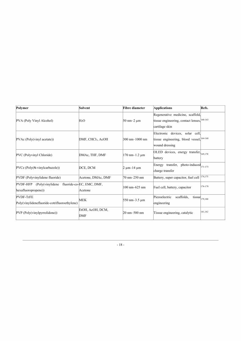
Polymer Solvent Fibre diameter Applications Refs.
CA (Cellulose acetate) DMF, Acetone, DMAc,
AcOH 30 nm–1 μm Biosensors 66-69
Chitosan HCl, AcOH, FA, DCM,
TFA 200 nm–1000 nm
Biomedical, drug delivery, tissue
engineering 70-72
Poly[(9,9-di-n-octylfluorenyl-2,7-diyl)alt-
(benzo[2,1,3] thiadiazol-4,8-diyl)]
THF, DMSO, Toluene,
CHCl3 100 nm–700 nm
Photonics, optoelectronics, lab-
on-chips 73,74
P(LLA-CL) Poly(L-lactide-co-
epsiloncaprolactone) Acetone 200 nm–1.5 μm
Tissue engineering, scaffold,
blood vessel 75,76
PA (Polyamide) DMF, HFP, FA 50 nm–500 nm Nano-composite, optical-sensors 77-79
PAA (Poly acrylic acid) DMF, H2O 100 nm–400 nm Optical Sensors, gas sensors 78,80,81
PAN (Polyacrylonitrile) DMF 50 nm–300 nm Nano-electronics, carbon
nanofibres, composites 65,82-84
PANi (Polyaniline) CHCl3, SA, HFP 96 nm–500 nm
Nano-electronics, p–n junctions,
chemical sensors and micro-
electrodes
65,85
Table 2.2 Commonly used polymer materials in electrospinning
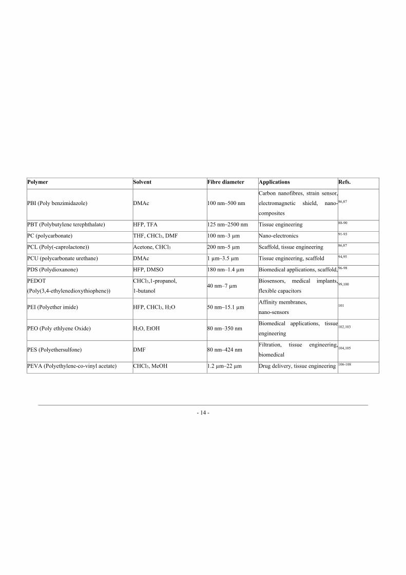
- 14 -
Polymer Solvent Fibre diameter Applications Refs.
PBI (Poly benzimidazole) DMAc 100 nm–500 nm
Carbon nanofibres, strain sensor,
electromagnetic shield, nano-
composites
86,87
PBT (Polybutylene terephthalate) HFP, TFA 125 nm–2500 nm Tissue engineering 88-90
PC (polycarbonate) THF, CHCl3, DMF 100 nm–3 μm Nano-electronics 91-93
PCL (Poly(-caprolactone)) Acetone, CHCl3 200 nm–5 μm Scaffold, tissue engineering 86,87
PCU (polycarbonate urethane) DMAc 1 μm–3.5 μm Tissue engineering, scaffold 94,95
PDS (Polydioxanone) HFP, DMSO 180 nm–1.4 μm Biomedical applications, scaffold, 96-98
PEDOT
(Poly(3,4-ethylenedioxythiophene))
CHCl3,1-propanol,
1-butanol 40 nm–7 μm
Biosensors, medical implants,
flexible capacitors 99,100
PEI (Polyether imide) HFP, CHCl3, H2O 50 nm–15.1 μm Affinity membranes,
nano-sensors 101
PEO (Poly ethlyene Oxide) H2O, EtOH 80 nm–350 nm Biomedical applications, tissue
engineering 102,103
PES (Polyethersulfone) DMF 80 nm–424 nm Filtration, tissue engineering,
biomedical 104,105
PEVA (Polyethylene-co-vinyl acetate) CHCl3, MeOH 1.2 μm–22 μm Drug delivery, tissue engineering 106-108
- 15 -
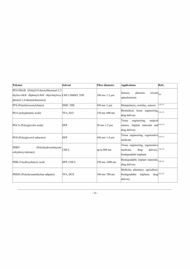
Polymer Solvent Fibre diameter Applications Refs.
PFO-PBAB (Poly[(9,9-dioctylfluorenyl-2,7-
diyl)co-(N,N -diphenyl)-N,N -di(p-butyloxy-
phenyl)-1,4-diaminobenzene])
CHCl3 DMSO, THF 180 nm–1.5 μm Sensors, photonic circuits
optoelectronic 109
PFS (Poly(ferrocenylsilane)) DMF, THF, 450 nm–2 μm Manipulators, switches, sensors 110,111
PGA (polyglutamic acid)) TFA, H2O 150 nm–600 nm Biomedical, tissue engineering,
drug delivery 112,113
PGCA (Poly(glycolic acid)) HFP 50 nm–1.5 μm
Tissue engineering, surgical
sutures, implant materials and
drug delivery
114,115
PGS (Poly(glycerol sebacate)) HFP 450 nm–1.4 μm Tissue engineering, regenerative
medicine 116,117
PHBV (Poly(hydroxybutyrate-
cohydroxyvalerate)) CHCl3 up to 800 nm
Tissue engineering, regenerative
medicine, drug delivery,
biodegradable implants
118,119
PHB (3-hydroxybutyric acid) HFP, CHCl3 250 nm–1000 nm Biodegradable implant materials,
drug delivery 120,121
PHMA (Poly(hexamethylene adipate)) TFA, DCE 100 nm–700 nm
Medicine, pharmacy, agriculture,
biodegradable implants, drug
delivery
122,123
- 16 -
Polymer Solvent Fibre diameter Applications Refs.
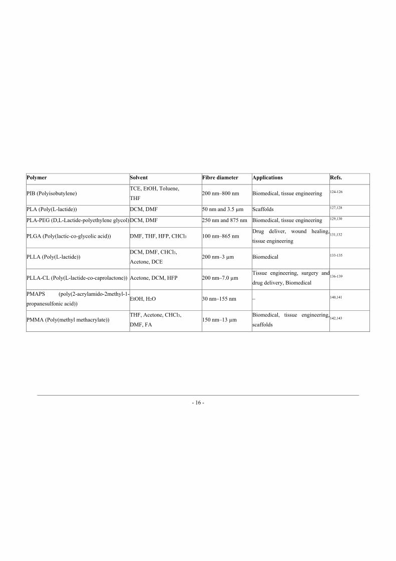
PIB (Polyisobutylene) TCE, EtOH, Toluene,
THF 200 nm–800 nm Biomedical, tissue engineering 124-126
PLA (Poly(L-lactide)) DCM, DMF 50 nm and 3.5 μm Scaffolds 127,128
PLA-PEG (D,L-Lactide-polyethylene glycol) DCM, DMF 250 nm and 875 nm Biomedical, tissue engineering 129,130
PLGA (Poly(lactic-co-glycolic acid)) DMF, THF, HFP, CHCl3 100 nm–865 nm Drug deliver, wound healing,
tissue engineering 131,132
PLLA (Poly(L-lactide)) DCM, DMF, CHCl3,
Acetone, DCE 200 nm–3 μm Biomedical 133-135
PLLA-CL (Poly(L-lactide-co-caprolactone)) Acetone, DCM, HFP 200 nm–7.0 μm Tissue engineering, surgery and
drug delivery, Biomedical 136-139
PMAPS (poly(2-acrylamido-2methyl-1-
propanesulfonic acid)) EtOH, H2O 30 nm–155 nm – 140,141
PMMA (Poly(methyl methacrylate)) THF, Acetone, CHCl3,
DMF, FA 150 nm–13 μm
Biomedical, tissue engineering,
scaffolds 142,143
- 17 -
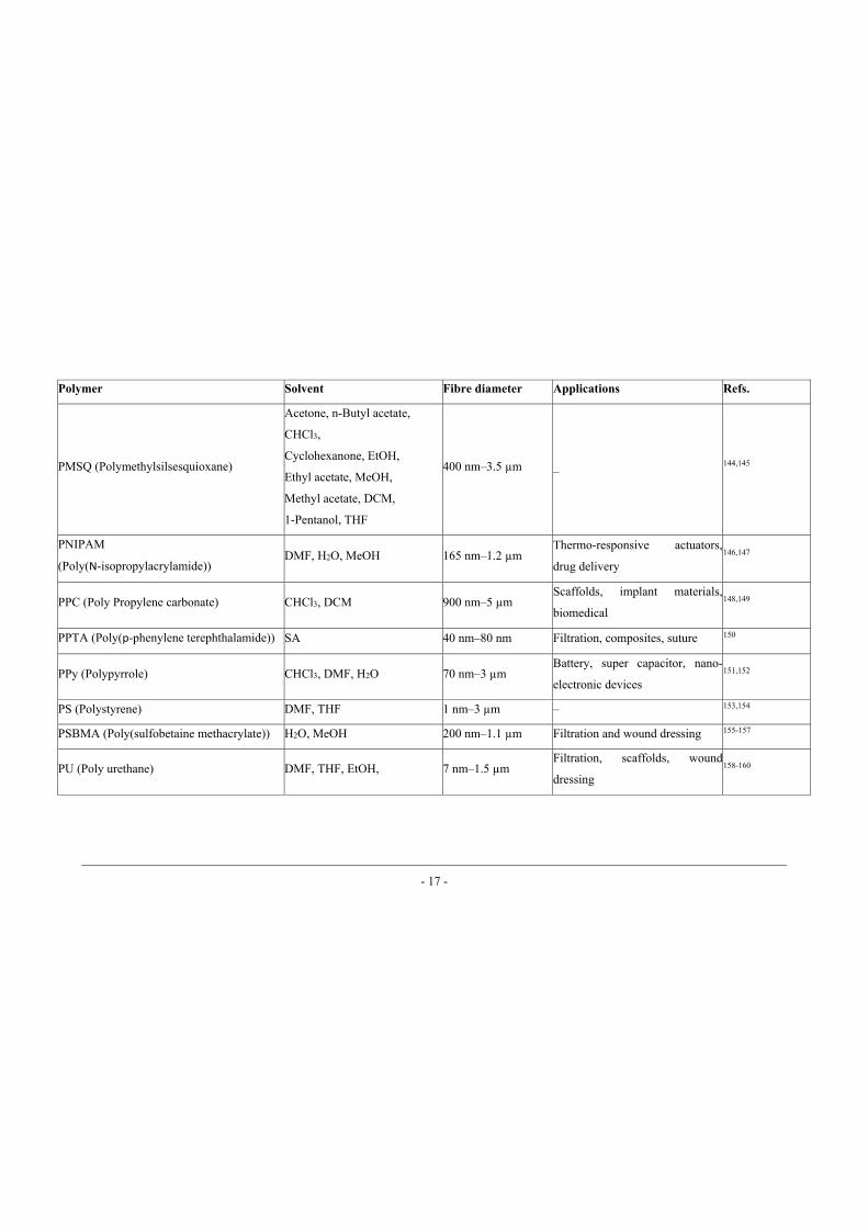
Polymer Solvent Fibre diameter Applications Refs.
PMSQ (Polymethylsilsesquioxane)
Acetone, n-Butyl acetate,
CHCl3,
Cyclohexanone, EtOH,
Ethyl acetate, MeOH,
Methyl acetate, DCM,
1-Pentanol, THF
400 nm–3.5 μm _ 144,145
PNIPAM
(Poly(N-isopropylacrylamide)) DMF, H2O, MeOH 165 nm–1.2 μm
Thermo-responsive actuators,
drug delivery 146,147
PPC (Poly Propylene carbonate) CHCl3, DCM 900 nm–5 μm Scaffolds, implant materials,
biomedical 148,149
PPTA (Poly(p-phenylene terephthalamide)) SA 40 nm–80 nm Filtration, composites, suture 150
PPy (Polypyrrole) CHCl3, DMF, H2O 70 nm–3 μm Battery, super capacitor, nano-
electronic devices 151,152
PS (Polystyrene) DMF, THF 1 nm–3 μm – 153,154
PSBMA (Poly(sulfobetaine methacrylate)) H2O, MeOH 200 nm–1.1 μm Filtration and wound dressing 155-157
PU (Poly urethane) DMF, THF, EtOH, 7 nm–1.5 μm Filtration, scaffolds, wound
dressing 158-160
- 18 -
Polymer Solvent Fibre diameter Applications Refs.
PVA (Poly Vinyl Alcohol) H2O 50 nm–2 μm
Regenerative medicine, scaffold,
tissue engineering, contact lenses,
cartilage skin
160-163
PVAc (Poly(vinyl acetate)) DMF, CHCl3, AcOH 300 nm–1000 nm
Electronic devices, solar cell,
tissue engineering, blood vessel,
wound dressing
164-168
PVC (Polyvinyl Chloride) DMAc, THF, DMF 170 nm–1.2 μm OLED devices, energy transfer,
battery 169,170
PVCz (Poly(N-vinylcarbazole)) DCE, DCM 2 μm–14 μm Energy transfer, photo-induced
charge transfer 171-173
PVDF (Polyvinylidene fluoride) Acetone, DMAc, DMF 70 nm–250 nm Battery, super capacitor, fuel cell 174,175
PVDF-HFP (Poly(vinylidene fluoride-co-
hexafluoropropene))
EC, EMC, DMF,
Acetone 100 nm–625 nm Fuel cell, battery, capacitor 176-178
PVDF-TrFE
Poly(vinylidenefluoride-cotrifluoroethylene) MEK 550 nm–3.5 μm
Piezoelectric scaffolds, tissue
engineering 179,180
PVP (Poly(vinylpyrrolidone)) EtOH, AcOH, DCM,
DMF 20 nm–500 nm Tissue engineering, catalytic 181,182
- 19 -
Note:
1,2-dichloroethane DCE Ethylmethyl carbonate EMC 1,1,1,3,3,3-hexafluoro-2-propanol HFP Formic acid FA Acetic acid AcOH Methanol MeOH Chloroform CHCl3 Methylethylketone MEK Di chloroacetic acid DCA Sulfuric Acid SA Dichloromethane DCM Tetrahydrofuran THF Diluted hydrochloric acid HCl Trichloroethylene TCE Dimethyl sulfoxide DMSO Trifluoroacetic acid TFA Dimethylacetamide DMAc Water H2O Dimethylformamide DMF Ethylene carbonate EC Ethanol EtOH Ethylene dichloride EDC
Chapter 2: [Literature Review]
- 20 -
2.2 Electrospinning
Electrospinning has a number of advantages over other nanofibre making
techniques. This technique can produce long continuous fibres with controllable
diameter ranging from nanometers to microns. A wide variety of materials
including polymers, inorganic compounds, biomaterials, nanoparticles and
ceramics can be utilized to produce electrospun nanofibres. Fibrous membranes
made of electrospun nanofibres are highly porous with excellent pore
interconnectivity. Modified electrospinning techniques can produce nanofibres in a
number of different configurations, including sheath-core, side-by-side, islands-in-
a-sea and hollow nanofibres. Electrospinning parameters can be controlled easily
to produce nanofibres with desired surface morphology, fibre structure, component
and fibrous architecture.
Although electrospinning has proved its supremacy over other nanofibre
producing techniques, conventional needle electrospinning can only produce a
limited amount of nanofibres ranging from 0.1 to 1.0 gram per hour 183 or process
polymer solution with a flow rate of 1.0–5.0 mL/h 184. Some researchers increased
nanofibre production using gas-blowing 185-187, multi-jets 188-191 or multiple needles
192-195. Even with these techniques, the fibre productivity could only be increased to
a certain extent beyond that electrospinning process was adversely affected.
Needleless electrospinning was developed as an alternative for production
of nanofibres on much larger scale than conventional needle electrospinning. It not
only breaks the production limitation of electrospinning from needle nozzle 183, but
Chapter 2: [Literature Review]
- 21 -
also eliminates problems of inter-jet repulsion, needle-clogging and huge-space
requirement to setup a multi-needle system 192.
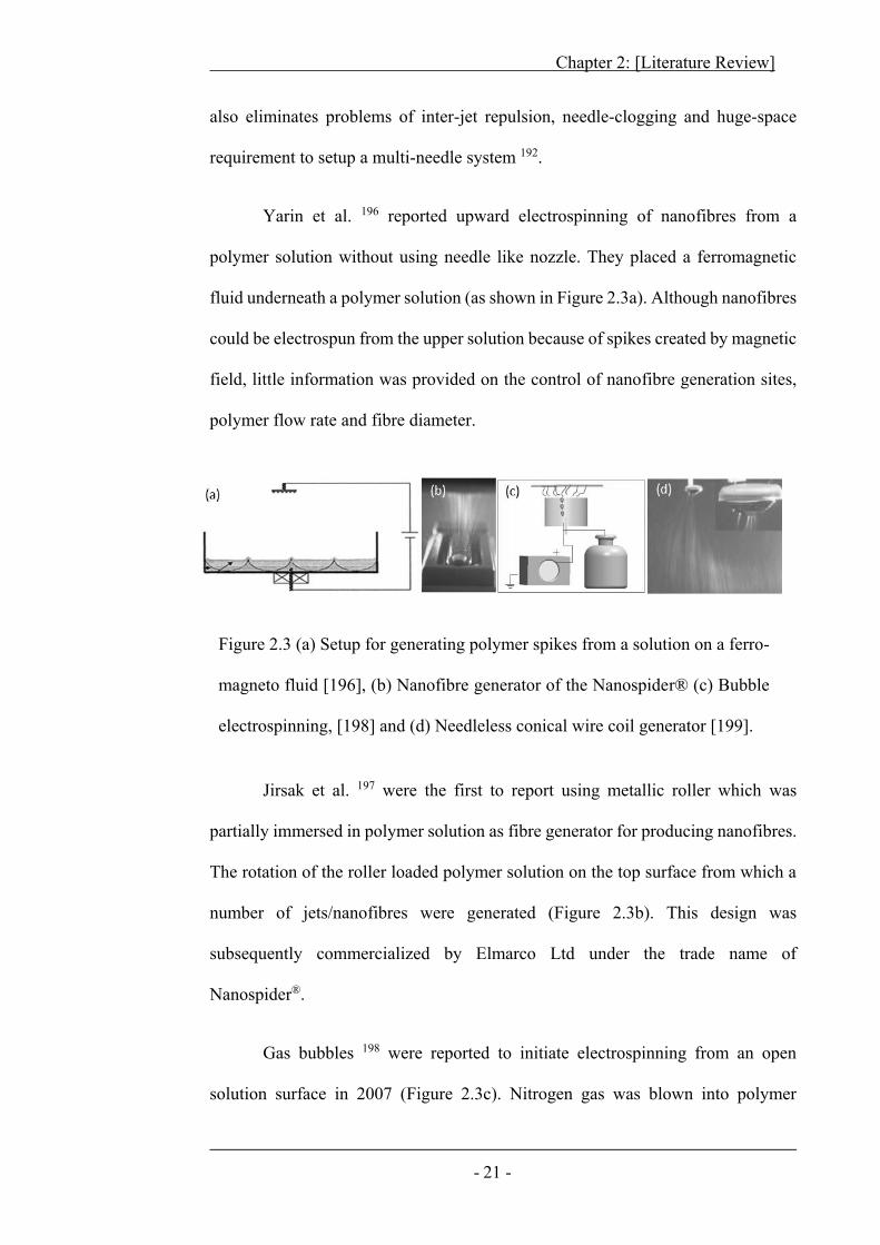
Yarin et al. 196 reported upward electrospinning of nanofibres from a
polymer solution without using needle like nozzle. They placed a ferromagnetic
fluid underneath a polymer solution (as shown in Figure 2.3a). Although nanofibres
could be electrospun from the upper solution because of spikes created by magnetic
field, little information was provided on the control of nanofibre generation sites,
polymer flow rate and fibre diameter.
Figure 2.3 (a) Setup for generating polymer spikes from a solution on a ferro-
magneto fluid [196], (b) Nanofibre generator of the Nanospider® (c) Bubble
electrospinning, [198] and (d) Needleless conical wire coil generator [199].
Jirsak et al. 197 were the first to report using metallic roller which was
partially immersed in polymer solution as fibre generator for producing nanofibres.
The rotation of the roller loaded polymer solution on the top surface from which a
number of jets/nanofibres were generated (Figure 2.3b). This design was
subsequently commercialized by Elmarco Ltd under the trade name of
Nanospider®.
Gas bubbles 198 were reported to initiate electrospinning from an open
solution surface in 2007 (Figure 2.3c). Nitrogen gas was blown into polymer
Chapter 2: [Literature Review]
- 22 -
solution to form multiple jets and then nanofibres. In 2009, a conical wire coil was
used as a fibre generator to prepare nanofibres. In this setup, the polymer solution
was conveyed to the spinning sites under the action of gravity and guided by the
coil structure (Figure 2.3d). This system can produce high-quality nanofibres with
a significantly increased production rate compared with needle electrospinning 199.
Later on, a few fibre generators, for example, metal plate 200, splashing spinneret
201, rotary cone 202, cylinder 203, and bowel edge 204 were reported for needleless
electrospinning.
The influences of spinneret geometry on needleless electrospinning process
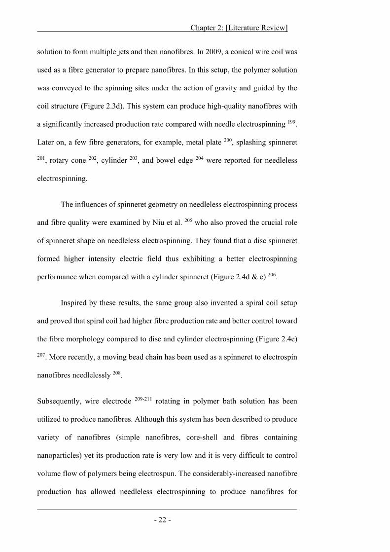
and fibre quality were examined by Niu et al. 205 who also proved the crucial role
of spinneret shape on needleless electrospinning. They found that a disc spinneret
formed higher intensity electric field thus exhibiting a better electrospinning
performance when compared with a cylinder spinneret (Figure 2.4d & e) 206.
Inspired by these results, the same group also invented a spiral coil setup
and proved that spiral coil had higher fibre production rate and better control toward
the fibre morphology compared to disc and cylinder electrospinning (Figure 2.4e)
207. More recently, a moving bead chain has been used as a spinneret to electrospin
nanofibres needlelessly 208.
Subsequently, wire electrode 209-211 rotating in polymer bath solution has been
utilized to produce nanofibres. Although this system has been described to produce
variety of nanofibres (simple nanofibres, core-shell and fibres containing
nanoparticles) yet its production rate is very low and it is very difficult to control
volume flow of polymers being electrospun. The considerably-increased nanofibre
production has allowed needleless electrospinning to produce nanofibres for
Chapter 2: [Literature Review]
- 23 -
practical applications. However, issues still remain in precisely controlling fibre
diameter, morphology and deposition, as well as polymer concentration during
needleless electrospinning.
Figure 2.4 Needleless generators and their electric field profiles (a) and
(d) disc generator, (b) and (e) cylinder generator, and (c) and (f) circular
coil generator [207].
Chapter 2: [Literature Review]
- 24 -
2.3 Fibre Alignment
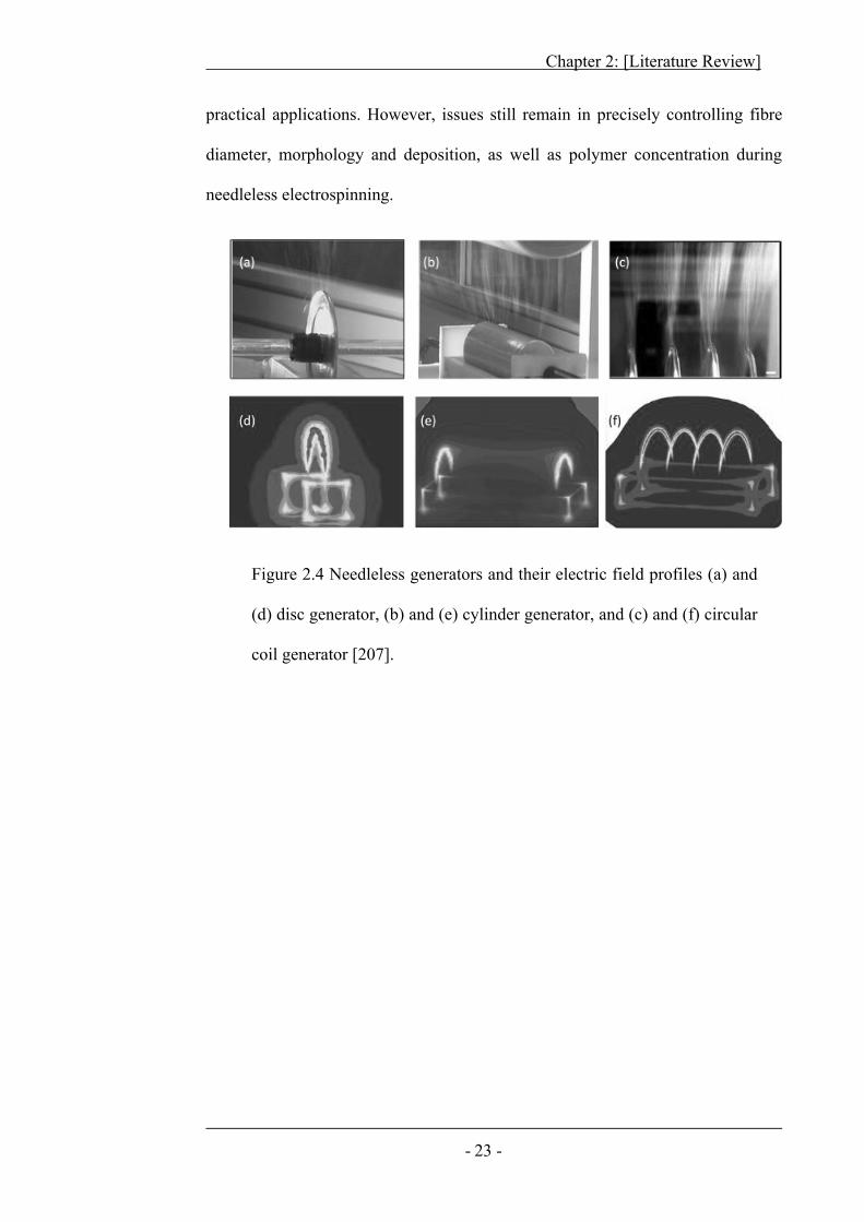
Early attempts to produce aligned nanofibres were carried out by collecting
nanofibres on high speed rotating collectors (Figure 2.5a & b) 212-214. The fibres
were taken away by rotating surface, forcing nanofibre deposition in much aligned
manner. Stationary collectors such as metal frame and parallel electrode were also
used for fibre alignment (Figure 2.5 c & d). A high degree of fibre alignment was
achieved between the electrodes. During electrospinning toward the parallel
electrodes, nanofibres tend to deposit on the surface where the electrical potential
is lowest. The attachment of the fibres on one of the electrodes leads to immediate
increase in the potential and the generation of a local field pushes the later deposited
fibre segment to align vertically on the electrode.
Figure 2.5 Fibre alignment using (a) high speed rotating collector [212], (b)
sharp edge collector [214], (c) frame electrode [215] and (d) parallel
electrode [216].
The fibres also preferably approach the second electrode, resulting in
bridging the fibre between the electrodes. In this way, up-coming nanofibres layer
up in aligned fashion. Apart from frame and parallel electrode stripe, blades, rings
and discs were also used for collecting aligned nanofibres. Such a gap-collection
resulted in aligned nanofibre bundles 215-223.
Chapter 2: [Literature Review]
- 25 -
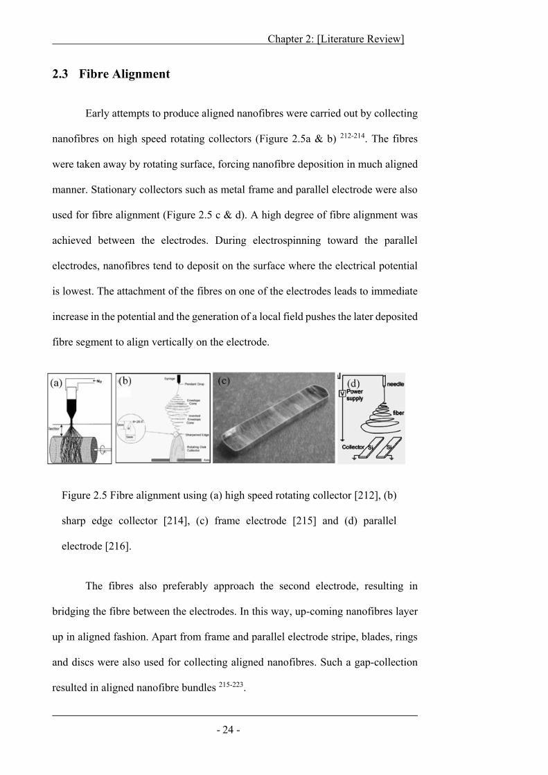
Some papers reported on preparation of aligned nanofibres using a rotating
roller in front of grounded sharp-edge counter electrode (Figure 2.6). The sharp-
edged configuration presents strong pointed electric field and attracts nanofibres
toward surface 213,217. The alignment direction of fibres on the roller collector can
be adjusted through the relative angle between the axis of the roller and the
electrospinning direction.
Figure 2.6 Intensified electric field using (a) sharp needle encompassed
in a drum cylinder [213], (b) parallel sharp edge plates [217] and (c)
sharp edge needle placed at an angle [217].
Chapter 2: [Literature Review]
- 26 -
2.4 Discontinuous Nanofibre Bundles
Recently, considerable efforts have been made to prepare yarns from
electrospun nanofibres. Early papers have focused on the production of short fibre
bundles, either twisted or non-twisted. Although some authors named these fibrous
structures as yarns, they are actually beyond the scope of yarns due to the lack of
basic features defined (section 2.1).
2.4.1 Non-Twisted Nanofibre Bundles
Fong et al. 224 produced aligned nanofibre bundles by swinging a grounded-
frame between nozzle and collector electrode. The vibrating frame forced
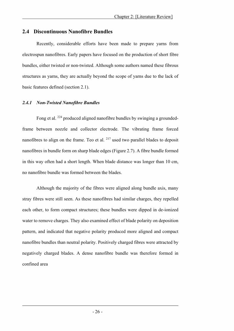
nanofibres to align on the frame. Teo et al. 217 used two parallel blades to deposit
nanofibres in bundle form on sharp blade edges (Figure 2.7). A fibre bundle formed
in this way often had a short length. When blade distance was longer than 10 cm,
no nanofibre bundle was formed between the blades.
Although the majority of the fibres were aligned along bundle axis, many
stray fibres were still seen. As these nanofibres had similar charges, they repelled
each other, to form compact structures; these bundles were dipped in de-ionized
water to remove charges. They also examined effect of blade polarity on deposition
pattern, and indicated that negative polarity produced more aligned and compact
nanofibre bundles than neutral polarity. Positively charged fibres were attracted by
negatively charged blades. A dense nanofibre bundle was therefore formed in
confined area
Chapter 2: [Literature Review]
- 27 -
Figure 2.7 Photograph showing short nanofibre bundles over
sharp blade edges [217].
Jalili et al. 225 analysed the effect of gap between two collector plates on the
formation of nanofibre bundles. It was indicated that the overall nanofibre density
decreased as distance between parallel plates increased, while the degree of
nanofibre alignment increased first with the increase in distance, and then declined
with a further increase in distance.
Some of the studies have mentioned the formation of self-assembled
bundles directly on the electrode collector 37,226. Intrinsic ionic conduction 37 or
conductivity induced by the addition of salt to polymer solution 226 were reported
to cause nanofibres to deposit perpendicularly to the collector, and further
electrospinning of fibres resulted in formation of loosely-packed bundles.
Most of electrospinning experiments have utilized DC (direct current)
power supply to produce nanofibres. Maheshwari et al. 227 used AC (alternate
current) power supply to electrospin nanofibre bundles. By using AC power supply
during electrospinning, polymer jet was split into multiple jets. Before reaching
collector electrode, these jets bundled together. It was suggested that change of
electric polarity from positive to negative weakened the electric field in single cycle
Chapter 2: [Literature Review]
- 28 -
of AC, thus hindering jet stretching. In next AC cycle, change of polarity, caused
jet split into multi-filament from previously inadequately stretched jet. As both
negative and positive charges were induced in multi-jets by polarity change in
single cycle, the fibres attracted each other to form a bundle in mid-air. In addition,
combination of negative and positive charges neutralized overall fibre bundle, fibre
bundles could be easily removed even with a small puff of air.
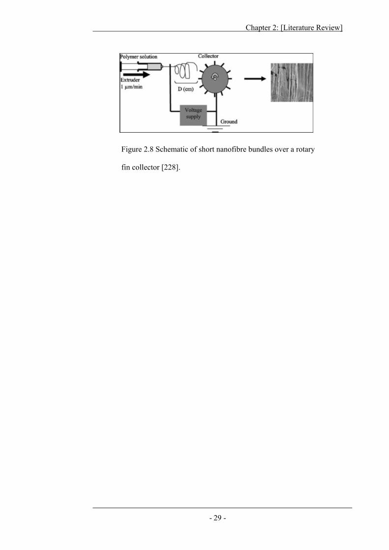
Afifi et al. 228 prepared aligned nanofibre bundles on a special rotary
collector with fins as illustrated in Figure 2.8. Needle nozzle was placed in front of
a rotating collector. Nanofibres aligned over the fins were removed as nanofibre
bundles. It was reported that collector rotary speed showed little effect on nanofibre
bundle formation. However, applied voltage and nozzle-collector distance were
important parameters affecting the formation of nanofibre bundle. It was also
indicated that heating and drafting improved mechanical properties and crystal
orientation of these nanofibre bundles.
Apart from needle electrospinning, needleless electrospinning has also been
reported to form nanofibre bundle on a stationary target. For example Chvojka et
al. 38 reported using Nanospider® with double comb-like target to collect nanofibre
bundles. Nanofibres had better alignment and more compact structure on the spikes
of same comb whereas nanofibres bridging between the two combs were randomly
arranged. These bundles had beaded-structures along with nanofibres, a typical
problem often seen in needleless electrospinning systems, as there is no control over
polymer flow rate, nanofibre generation sites and solvent evaporation from
needleless generators.
Chapter 2: [Literature Review]
- 29 -
Figure 2.8 Schematic of short nanofibre bundles over a rotary
fin collector [228].
Chapter 2: [Literature Review]
- 30 -
2.4.2 Twisted Short Bundles
In conventional fibre and textile areas, twists were often inserted into a fibre
bundle with the purpose of improving the mechanical strength, because twists can
compress the bundle and increase adhesion and friction between fibres. Moreover,
twists improve the bundle uniformity. Several works have been reported to insert
twists into nanofibre bundles either through a post-spinning process or during
electrospinning.
2.4.2.1 Post-electrospinning Twisting
A few groups have reported the preparation of twisted nanofibre bundles by
cutting electrospun web into narrow strips and subsequently twisting them 229-231.
Fennessey et al. 229 used fast rotating collector electrode to produce aligned PAN
nanofibre webs. These webs were utilized to prepare fibre bundles. After twisting,
these bundles were rinsed with de-ionized water to remove remaining charges. They
observed an initial increase in ultimate strength and modulus with increasing twist
angle. However with further increase in twist, the mechanical properties decreased.
Stainless-steel annular collector has been used to collect highly aligned
PAN nanofibres on its periphery 232. Circular edge condensed electric field on the
annular collector circumference, resulting in aligned deposition of nanofibres as
thick fibre bundle. These aligned nanofibre bundles were stretched and twisted by
careful removal from the collector to form short twisted bundles.
He et al. 233 used co-axial electrospinning to load a drug into fibre bundles.
Highly aligned PLLA nanofibres were electrospun and deposited on a fast rotating
wheel. These bundles were twisted and hot-stretched on a custom made stretching
Chapter 2: [Literature Review]
- 31 -
assembly to improve mechanical properties. Loading of drug into fibre showed
improvement in fibre mechanical properties. Drug particles in the fibre can act as a
filler to reinforce the fibres. The composite structure stiffened the fibres and
reduced the overall plasticity of the fibre bundle.
Moon et al. 230 studied the effect of carbonization temperatures, heating
rates, heat-exposure time and drawing ratio on ultimate strength of PAN nanofibre
bundles converted into carbon nanofibre bundles. The ultimate tensile strength of
PAN cut-strip-bundles after carbonization was 1.0 GPa, whereas the twisted PAN
nanofibre bundles after carbonization showed improved ultimate tensile strength of
1.7 GPa.
Uddin et al 234 added MWCNTs (multi walled carbon nanotubes) into PAN
nanofibres through electrospinning. They observed improvement of mechanical
performance when MWCNTs were well dispersed into the PAN nanofibres in the
cut-strip-twisted bundles.
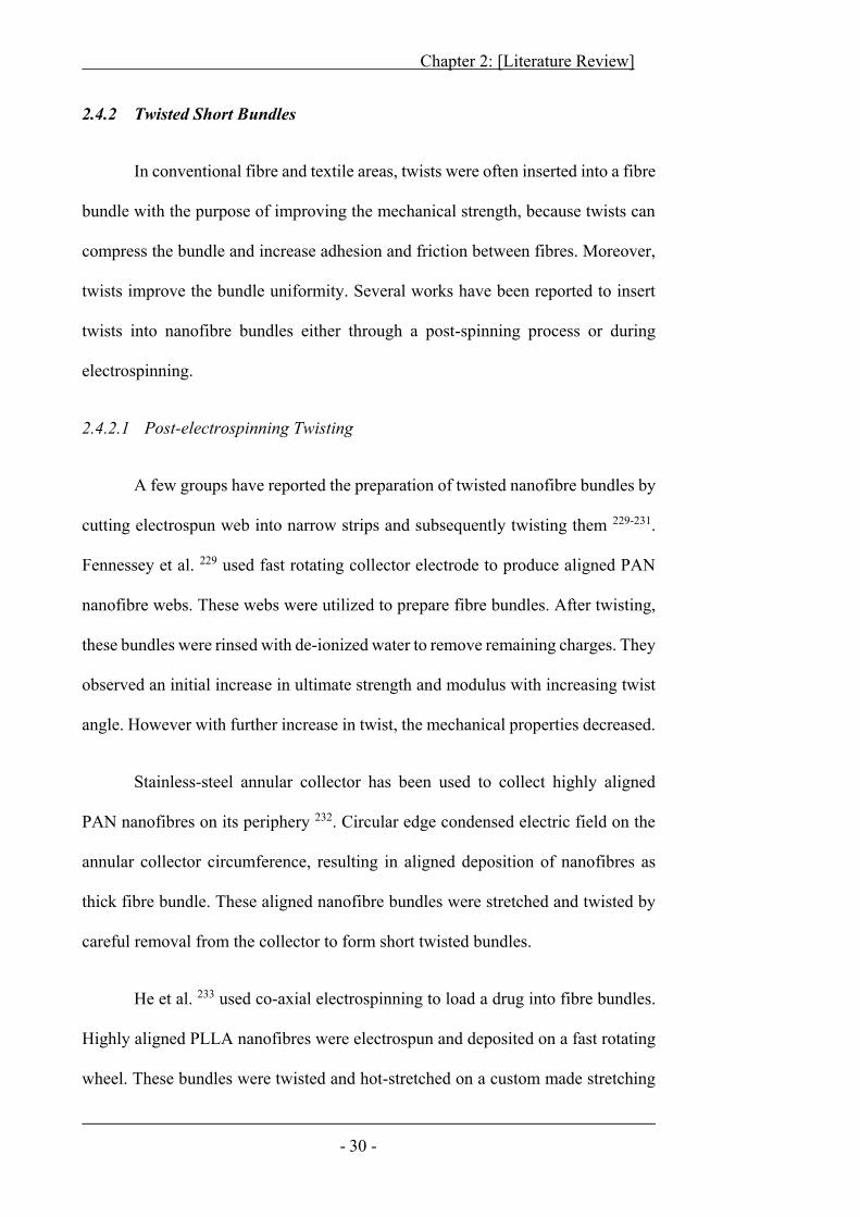
Zhou et al. 231 twisted short nanofibre bundles from PVDF-HFP nanofibre
web collected on a high-speed drum collector, and studied the effect of fibre
orientation, fibre diameter, morphology and twist level on the tensile strength
properties of bundles (Figure 2.9). It was found that fibre quality, diameter and
orientation played important roles in the final strength. Finer uniform fibres gave
better mechanical properties. Higher level of twist can be inserted in finer bead-free
fibres than beaded fibres. Yarn produced from strips cut parallel to fibre direction
had much higher tensile strength and modulus than strips cut perpendicular or at an
angle of 45o to the fibre orientation 231.
Chapter 2: [Literature Review]
- 32 -
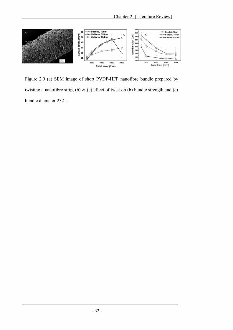
Figure 2.9 (a) SEM image of short PVDF-HFP nanofibre bundle prepared by
twisting a nanofibre strip, (b) & (c) effect of twist on (b) bundle strength and (c)
bundle diameter[232] .
Chapter 2: [Literature Review]
- 33 -
2.4.2.2 Direct Electrospinning
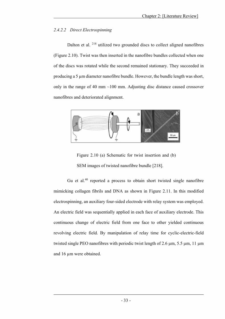
Dalton et al. 218 utilized two grounded discs to collect aligned nanofibres
(Figure 2.10). Twist was then inserted in the nanofibre bundles collected when one
of the discs was rotated while the second remained stationary. They succeeded in
producing a 5 μm diameter nanofibre bundle. However, the bundle length was short,
only in the range of 40 mm ~100 mm. Adjusting disc distance caused crossover
nanofibres and deteriorated alignment.
Figure 2.10 (a) Schematic for twist insertion and (b)
SEM images of twisted nanofibre bundle [218].
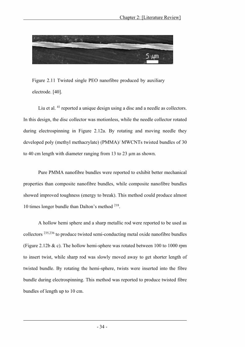
Gu et al.40 reported a process to obtain short twisted single nanofibre
mimicking collagen fibrils and DNA as shown in Figure 2.11. In this modified
electrospinning, an auxiliary four-sided electrode with relay system was employed.
An electric field was sequentially applied in each face of auxiliary electrode. This
continuous change of electric field from one face to other yielded continuous
revolving electric field. By manipulation of relay time for cyclic-electric-field
twisted single PEO nanofibres with periodic twist length of 2.6 μm, 5.5 μm, 11 μm
and 16 μm were obtained.
Chapter 2: [Literature Review]
- 34 -
Liu et al. 41 reported a unique design using a disc and a needle as collectors.
In this design, the disc collector was motionless, while the needle collector rotated
during electrospinning in Figure 2.12a. By rotating and moving needle they
developed poly (methyl methacrylate) (PMMA)/ MWCNTs twisted bundles of 30
to 40 cm length with diameter ranging from 13 to 23 μm as shown.
Pure PMMA nanofibre bundles were reported to exhibit better mechanical
properties than composite nanofibre bundles, while composite nanofibre bundles
showed improved toughness (energy to break). This method could produce almost
10 times longer bundle than Dalton’s method 218.
A hollow hemi sphere and a sharp metallic rod were reported to be used as
collectors 235,236 to produce twisted semi-conducting metal oxide nanofibre bundles
(Figure 2.12b & c). The hollow hemi-sphere was rotated between 100 to 1000 rpm
to insert twist, while sharp rod was slowly moved away to get shorter length of
twisted bundle. By rotating the hemi-sphere, twists were inserted into the fibre
bundle during electrospinning. This method was reported to produce twisted fibre
bundles of length up to 10 cm.
Figure 2.11 Twisted single PEO nanofibre produced by auxiliary
electrode. [40].
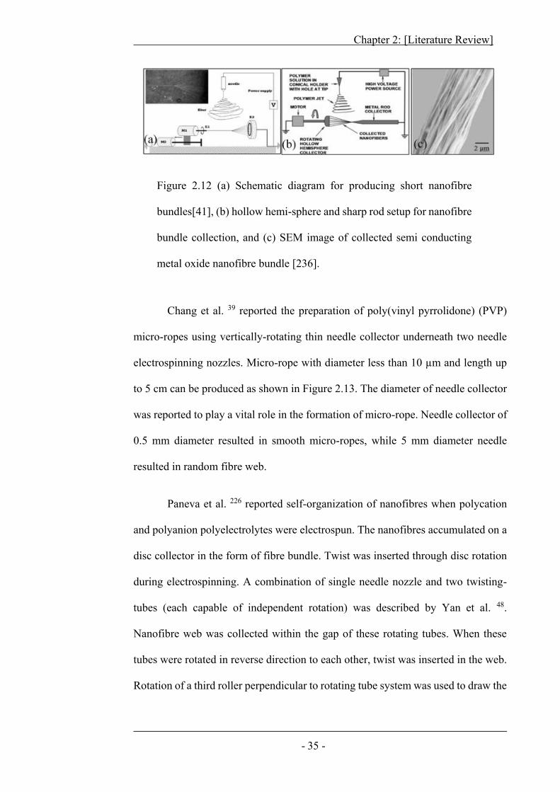
Chapter 2: [Literature Review]
- 35 -
Figure 2.12 (a) Schematic diagram for producing short nanofibre
bundles[41], (b) hollow hemi-sphere and sharp rod setup for nanofibre
bundle collection, and (c) SEM image of collected semi conducting
metal oxide nanofibre bundle [236].
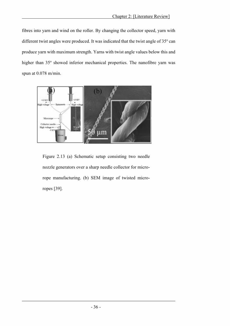
Chang et al. 39 reported the preparation of poly(vinyl pyrrolidone) (PVP)
micro-ropes using vertically-rotating thin needle collector underneath two needle
electrospinning nozzles. Micro-rope with diameter less than 10 μm and length up
to 5 cm can be produced as shown in Figure 2.13. The diameter of needle collector
was reported to play a vital role in the formation of micro-rope. Needle collector of
0.5 mm diameter resulted in smooth micro-ropes, while 5 mm diameter needle
resulted in random fibre web.
Paneva et al. 226 reported self-organization of nanofibres when polycation
and polyanion polyelectrolytes were electrospun. The nanofibres accumulated on a
disc collector in the form of fibre bundle. Twist was inserted through disc rotation
during electrospinning. A combination of single needle nozzle and two twisting-
tubes (each capable of independent rotation) was described by Yan et al. 48.
Nanofibre web was collected within the gap of these rotating tubes. When these
tubes were rotated in reverse direction to each other, twist was inserted in the web.
Rotation of a third roller perpendicular to rotating tube system was used to draw the
Chapter 2: [Literature Review]
- 36 -
fibres into yarn and wind on the roller. By changing the collector speed, yarn with
different twist angles were produced. It was indicated that the twist angle of 35o can
produce yarn with maximum strength. Yarns with twist angle values below this and
higher than 35o showed inferior mechanical properties. The nanofibre yarn was
spun at 0.078 m/min.
Figure 2.13 (a) Schematic setup consisting two needle
nozzle generators over a sharp needle collector for micro-
rope manufacturing. (b) SEM image of twisted micro-
ropes [39].
Chapter 2: [Literature Review]
- 37 -
2.5 Non-Twisted Filament Yarns
Two types of continuous nanofibre bundles were produced from electrospun
nanofibres. Non-twisted nanofibre bundles here also referred to as filament yarns,
while twisted continuous fibre bundles actually meet all the yarn characteristics. A
number of researchers have produced such nanofibre structures.
Ko et al. 42 reported a setup to prepare continuous nanofibre filament yarns.
They co-electrospun polylactic acid (PLA) and polyacrylonitrile (PAN) solution
containing SWCNTs (single wall carbon nanotubes) on a rotating cylindrical
collector. A continuous web was electrospun from a vertically placed
electrospinning nozzle. Fibres formed a suspended web in the air, which was
manually taken to the winder (Figure 2.14). Upcoming fibres deposited on the
previously deposited fibres. In this way, a continuous strand of nanofibres was
obtained. Although a schematic of twisted nanofibre yarn assembly was presented
in the paper, little detail was given.
Pan et al. 44 reported a conjugated system that can produce both positively
and negatively charged nanofibres simultaneously (Figure 2.15). Two needle
nozzles were independently connected to the positive and negative electrodes of
high voltage power supply. Oppositely charged nanofibres were electrospun from
the nozzles, which met in an intermediate area where charges were neutralized.
Upon drawing fibres from the fibre accumulation zone and transferring to a rotating
drum, aligned fibre filament yarn can be wound continuously
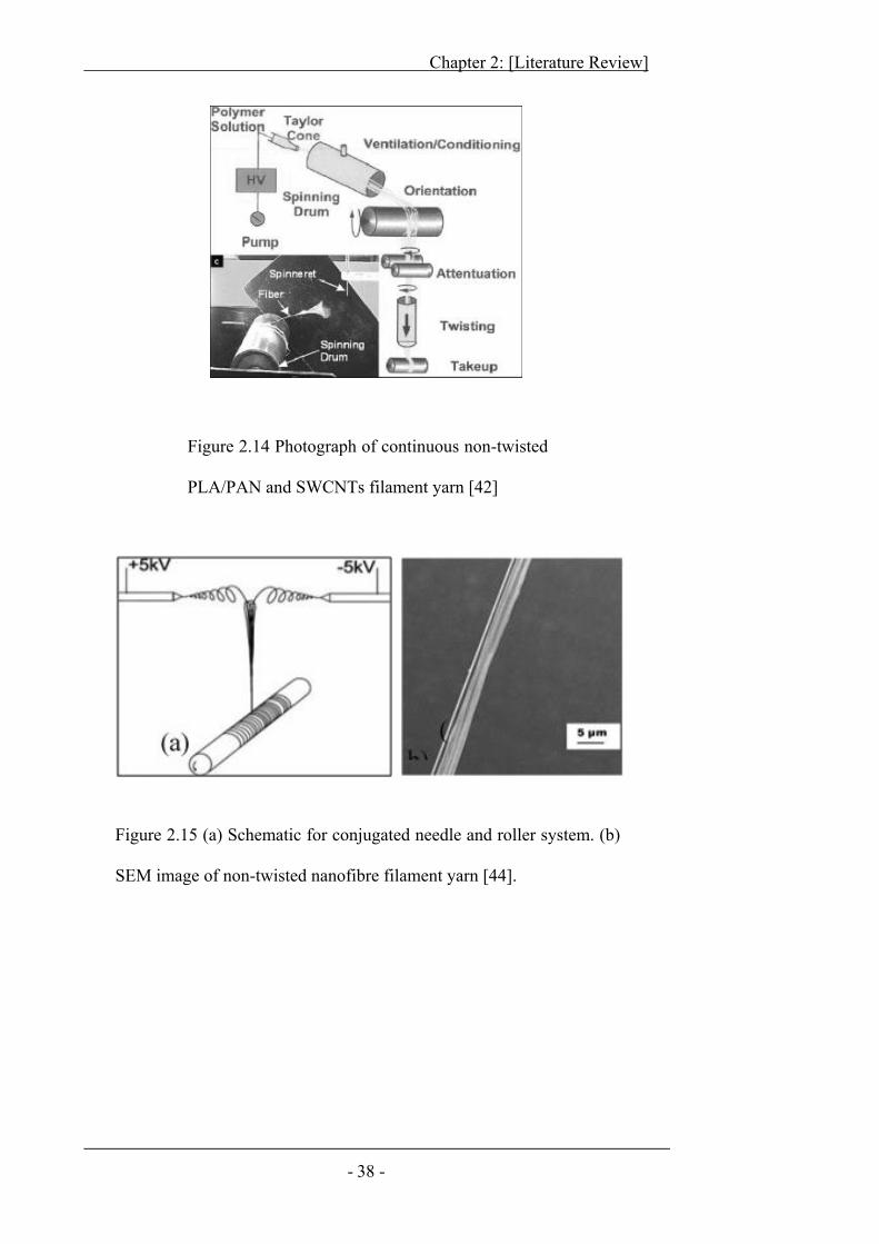
Chapter 2: [Literature Review]
- 38 -
Figure 2.14 Photograph of continuous non-twisted
PLA/PAN and SWCNTs filament yarn [42]
Figure 2.15 (a) Schematic for conjugated needle and roller system. (b)
SEM image of non-twisted nanofibre filament yarn [44].
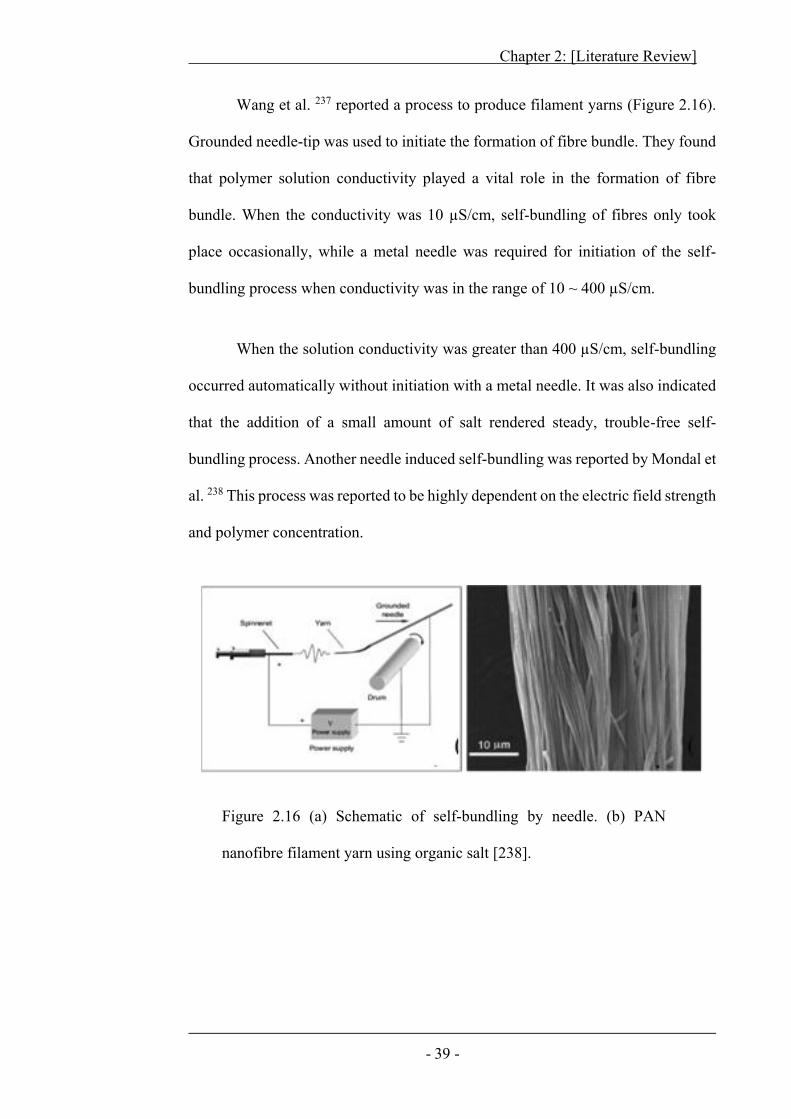
Chapter 2: [Literature Review]
- 39 -
Wang et al. 237 reported a process to produce filament yarns (Figure 2.16).
Grounded needle-tip was used to initiate the formation of fibre bundle. They found
that polymer solution conductivity played a vital role in the formation of fibre
bundle. When the conductivity was 10 μS/cm, self-bundling of fibres only took
place occasionally, while a metal needle was required for initiation of the self-
bundling process when conductivity was in the range of 10 ~ 400 μS/cm.
When the solution conductivity was greater than 400 μS/cm, self-bundling
occurred automatically without initiation with a metal needle. It was also indicated
that the addition of a small amount of salt rendered steady, trouble-free self-
bundling process. Another needle induced self-bundling was reported by Mondal et
al. 238 This process was reported to be highly dependent on the electric field strength
and polymer concentration.
Figure 2.16 (a) Schematic of self-bundling by needle. (b) PAN
nanofibre filament yarn using organic salt [238].
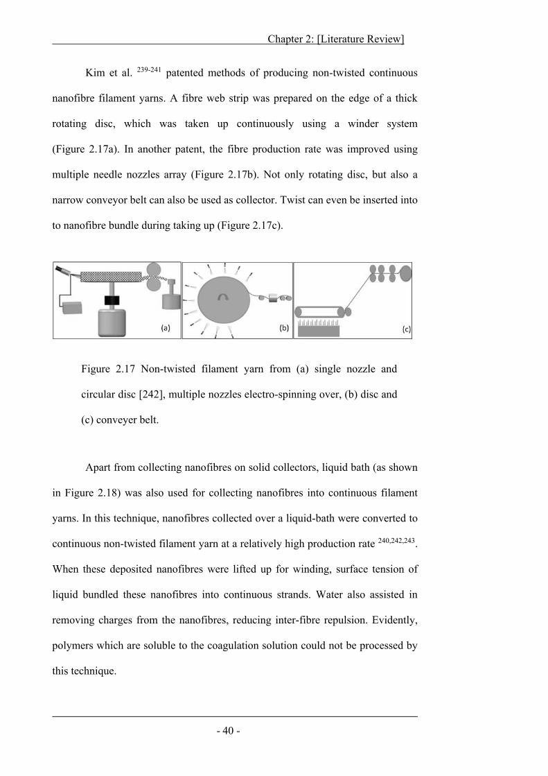
Chapter 2: [Literature Review]
- 40 -
Kim et al. 239-241 patented methods of producing non-twisted continuous
nanofibre filament yarns. A fibre web strip was prepared on the edge of a thick
rotating disc, which was taken up continuously using a winder system
(Figure 2.17a). In another patent, the fibre production rate was improved using
multiple needle nozzles array (Figure 2.17b). Not only rotating disc, but also a
narrow conveyor belt can also be used as collector. Twist can even be inserted into
to nanofibre bundle during taking up (Figure 2.17c).
Apart from collecting nanofibres on solid collectors, liquid bath (as shown
in Figure 2.18) was also used for collecting nanofibres into continuous filament
yarns. In this technique, nanofibres collected over a liquid-bath were converted to
continuous non-twisted filament yarn at a relatively high production rate 240,242,243.
When these deposited nanofibres were lifted up for winding, surface tension of
liquid bundled these nanofibres into continuous strands. Water also assisted in
removing charges from the nanofibres, reducing inter-fibre repulsion. Evidently,
polymers which are soluble to the coagulation solution could not be processed by
this technique.
Figure 2.17 Non-twisted filament yarn from (a) single nozzle and
circular disc [242], multiple nozzles electro-spinning over, (b) disc and
(c) conveyer belt.
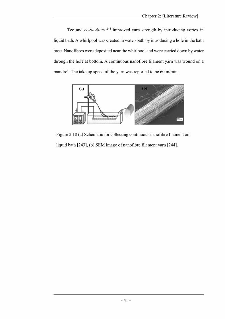
Chapter 2: [Literature Review]
- 41 -
Teo and co-workers 244 improved yarn strength by introducing vortex in
liquid bath. A whirlpool was created in water-bath by introducing a hole in the bath
base. Nanofibres were deposited near the whirlpool and were carried down by water
through the hole at bottom. A continuous nanofibre filament yarn was wound on a
mandrel. The take up speed of the yarn was reported to be 60 m/min.
Figure 2.18 (a) Schematic for collecting continuous nanofibre filament on
liquid bath [243], (b) SEM image of nanofibre filament yarn [244].
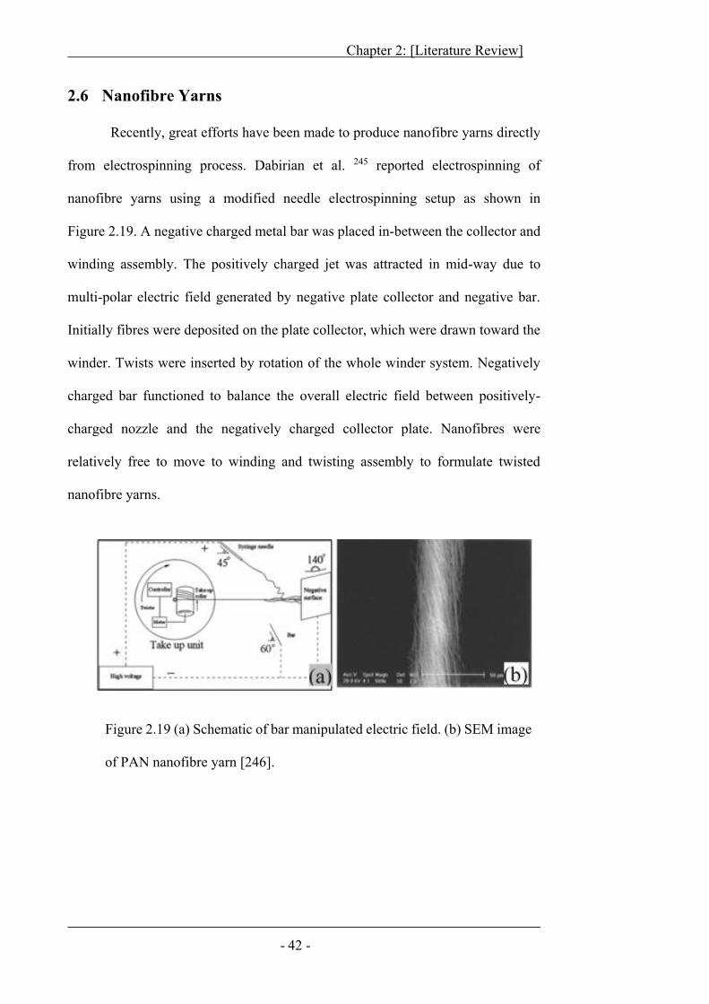
Chapter 2: [Literature Review]
- 42 -
2.6 Nanofibre Yarns
Recently, great efforts have been made to produce nanofibre yarns directly
from electrospinning process. Dabirian et al. 245 reported electrospinning of
nanofibre yarns using a modified needle electrospinning setup as shown in
Figure 2.19. A negative charged metal bar was placed in-between the collector and
winding assembly. The positively charged jet was attracted in mid-way due to
multi-polar electric field generated by negative plate collector and negative bar.
Initially fibres were deposited on the plate collector, which were drawn toward the
winder. Twists were inserted by rotation of the whole winder system. Negatively
charged bar functioned to balance the overall electric field between positively-
charged nozzle and the negatively charged collector plate. Nanofibres were
relatively free to move to winding and twisting assembly to formulate twisted
nanofibre yarns.
Figure 2.19 (a) Schematic of bar manipulated electric field. (b) SEM image
of PAN nanofibre yarn [246].
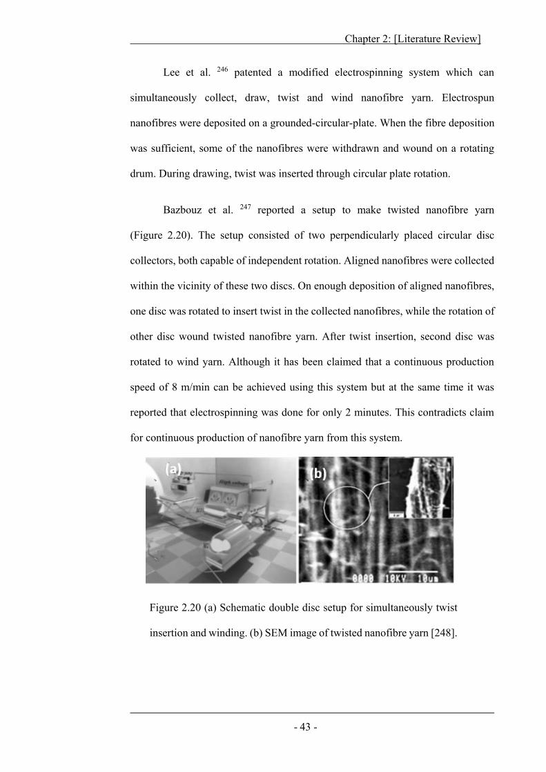
Chapter 2: [Literature Review]
- 43 -
Lee et al. 246 patented a modified electrospinning system which can
simultaneously collect, draw, twist and wind nanofibre yarn. Electrospun
nanofibres were deposited on a grounded-circular-plate. When the fibre deposition
was sufficient, some of the nanofibres were withdrawn and wound on a rotating
drum. During drawing, twist was inserted through circular plate rotation.
Bazbouz et al. 247 reported a setup to make twisted nanofibre yarn
(Figure 2.20). The setup consisted of two perpendicularly placed circular disc
collectors, both capable of independent rotation. Aligned nanofibres were collected
within the vicinity of these two discs. On enough deposition of aligned nanofibres,
one disc was rotated to insert twist in the collected nanofibres, while the rotation of
other disc wound twisted nanofibre yarn. After twist insertion, second disc was
rotated to wind yarn. Although it has been claimed that a continuous production
speed of 8 m/min can be achieved using this system but at the same time it was
reported that electrospinning was done for only 2 minutes. This contradicts claim
for continuous production of nanofibre yarn from this system.
Figure 2.20 (a) Schematic double disc setup for simultaneously twist
insertion and winding. (b) SEM image of twisted nanofibre yarn [248].
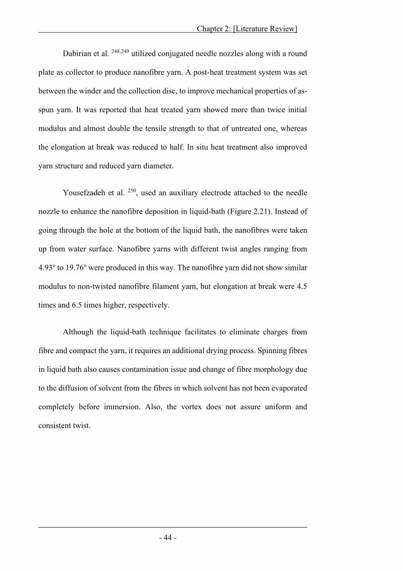
Chapter 2: [Literature Review]
- 44 -
Dabirian et al. 248,249 utilized conjugated needle nozzles along with a round
plate as collector to produce nanofibre yarn. A post-heat treatment system was set
between the winder and the collection disc, to improve mechanical properties of as-
spun yarn. It was reported that heat treated yarn showed more than twice initial
modulus and almost double the tensile strength to that of untreated one, whereas
the elongation at break was reduced to half. In situ heat treatment also improved
yarn structure and reduced yarn diameter.
Yousefzadeh et al. 250, used an auxiliary electrode attached to the needle
nozzle to enhance the nanofibre deposition in liquid-bath (Figure 2.21). Instead of
going through the hole at the bottom of the liquid bath, the nanofibres were taken
up from water surface. Nanofibre yarns with different twist angles ranging from
4.93o to 19.76o were produced in this way. The nanofibre yarn did not show similar
modulus to non-twisted nanofibre filament yarn, but elongation at break were 4.5
times and 6.5 times higher, respectively.
Although the liquid-bath technique facilitates to eliminate charges from
fibre and compact the yarn, it requires an additional drying process. Spinning fibres
in liquid bath also causes contamination issue and change of fibre morphology due
to the diffusion of solvent from the fibres in which solvent has not been evaporated
completely before immersion. Also, the vortex does not assure uniform and
consistent twist.
Chapter 2: [Literature Review]
- 45 -
The yarn collection on a solid surface not only improved yarn twist, but
fibre morphology also remained intact, which is better than the liquid-bath
collectors. However, the deposited nanofibres remained affixed on solid surface
while they were pulled and twisted to form yarn. No doubt, some friction and
tension is necessary to insert twist and draw nanofibres into proper nanofibre yarns,
but this restricted high speed yarn production.
The concept of intermediate collectors has been recently extended by some
researchers46,47,251,252. The intermediate collectors proved better alternative to
increase yarn production speed, but minimize nanofibre sticking issue. Afifi et al.
46 utilized single needle nozzle placed at an angle to vertical grounded funnel to
produce twisted nanofibre yarn (Figure 2.22).
Initially nanofibres deposited on funnel surface. With fibre accumulation,
web was formed on the vicinity of funnel. Manually drawing the web toward the
winder inserts twist. The effect of drawing on mechanical properties of nanofibre
yarn was assessed in this work. Electrospun yarn initially exhibited better
mechanical properties in comparison to un-stretched yarn with drawing, but further
drawing reduced the strength. The production speed of yarn from this system was
Figure 2.21 (a) Schematic of liquid vortex, (b) resultant twisted
nanofibre yarn. [251].
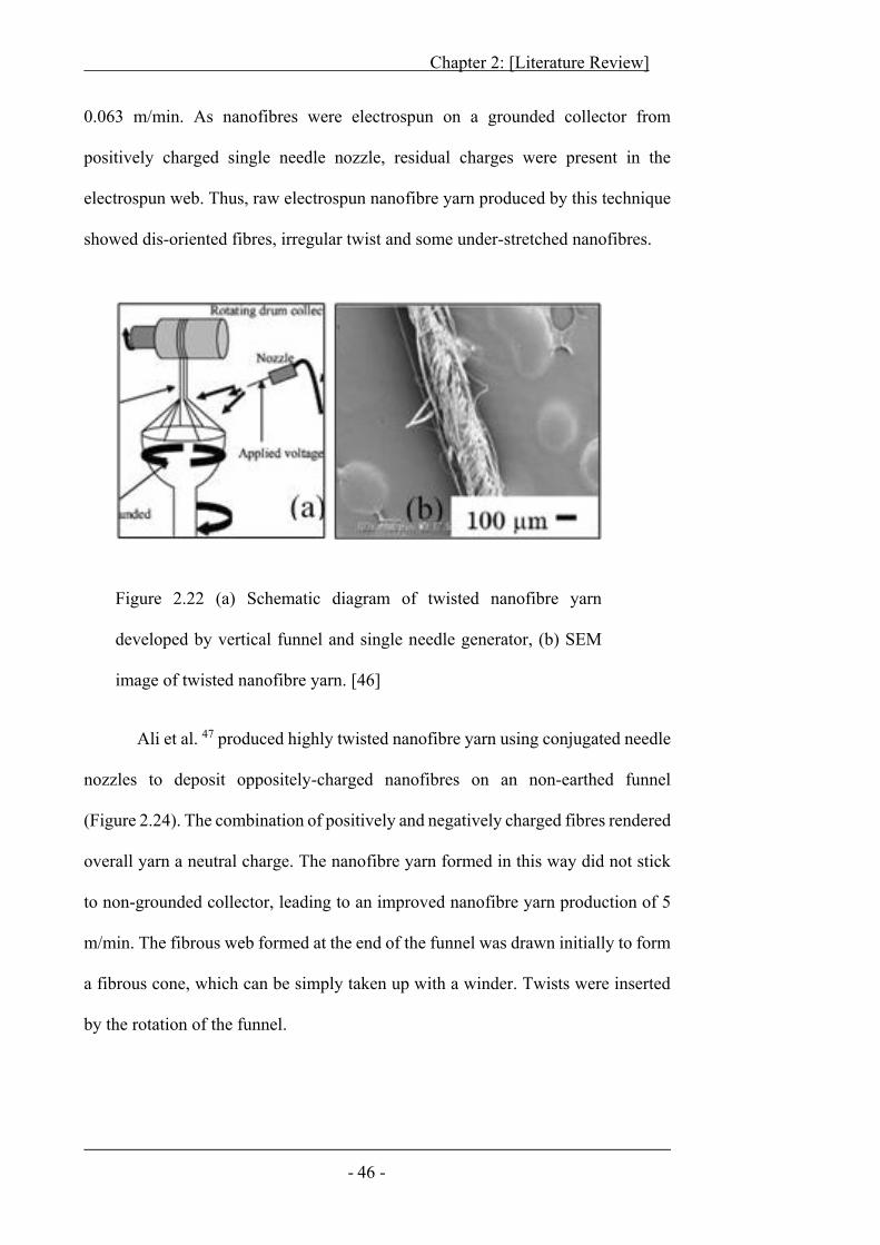
Chapter 2: [Literature Review]
- 46 -
0.063 m/min. As nanofibres were electrospun on a grounded collector from
positively charged single needle nozzle, residual charges were present in the
electrospun web. Thus, raw electrospun nanofibre yarn produced by this technique
showed dis-oriented fibres, irregular twist and some under-stretched nanofibres.
Ali et al. 47 produced highly twisted nanofibre yarn using conjugated needle
nozzles to deposit oppositely-charged nanofibres on an non-earthed funnel
(Figure 2.24). The combination of positively and negatively charged fibres rendered
overall yarn a neutral charge. The nanofibre yarn formed in this way did not stick
to non-grounded collector, leading to an improved nanofibre yarn production of 5
m/min. The fibrous web formed at the end of the funnel was drawn initially to form
a fibrous cone, which can be simply taken up with a winder. Twists were inserted
by the rotation of the funnel.
Figure 2.22 (a) Schematic diagram of twisted nanofibre yarn
developed by vertical funnel and single needle generator, (b) SEM
image of twisted nanofibre yarn. [46]
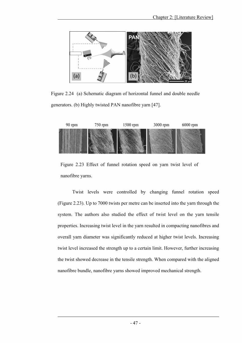
Chapter 2: [Literature Review]
- 47 -
Figure 2.23 Effect of funnel rotation speed on yarn twist level of
nanofibre yarns.
Twist levels were controlled by changing funnel rotation speed
(Figure 2.23). Up to 7000 twists per metre can be inserted into the yarn through the
system. The authors also studied the effect of twist level on the yarn tensile
properties. Increasing twist level in the yarn resulted in compacting nanofibres and
overall yarn diameter was significantly reduced at higher twist levels. Increasing
twist level increased the strength up to a certain limit. However, further increasing
the twist showed decrease in the tensile strength. When compared with the aligned
nanofibre bundle, nanofibre yarns showed improved mechanical strength.
Figure 2.24 (a) Schematic diagram of horizontal funnel and double needle
generators. (b) Highly twisted PAN nanofibre yarn [47].
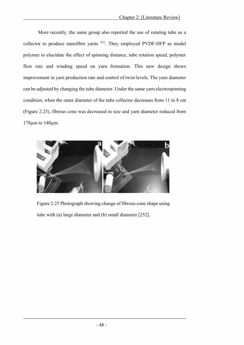
Chapter 2: [Literature Review]
- 48 -
More recently, the same group also reported the use of rotating tube as a
collector to produce nanofibre yarns 251. They employed PVDF-HFP as model
polymer to elucidate the effect of spinning distance, tube rotation speed, polymer
flow rate and winding speed on yarn formation. This new design shows
improvement in yarn production rate and control of twist levels. The yarn diameter
can be adjusted by changing the tube diameter. Under the same yarn electrospinning
condition, when the outer diameter of the tube collector decreases from 11 to 8 cm
(Figure 2.25), fibrous cone was decreased in size and yarn diameter reduced from
178μm to 140μm.
Figure 2.25 Photograph showing change of fibrous cone shape using
tube with (a) large diameter and (b) small diameter [252].
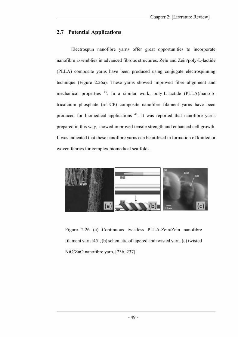
Chapter 2: [Literature Review]
- 49 -
2.7 Potential Applications
Electrospun nanofibre yarns offer great opportunities to incorporate
nanofibre assemblies in advanced fibrous structures. Zein and Zein/poly-L-lactide
(PLLA) composite yarns have been produced using conjugate electrospinning
technique (Figure 2.26a). These yarns showed improved fibre alignment and
mechanical properties 45. In a similar work, poly-L-lactide (PLLA)/nano-b-
tricalcium phosphate (n-TCP) composite nanofibre filament yarns have been
produced for biomedical applications 43. It was reported that nanofibre yarns
prepared in this way, showed improved tensile strength and enhanced cell growth.
It was indicated that these nanofibre yarns can be utilized in formation of knitted or
woven fabrics for complex biomedical scaffolds.
Figure 2.26 (a) Continuous twistless PLLA-Zein/Zein nanofibre
filament yarn [45], (b) schematic of tapered and twisted yarn. (c) twisted
NiO/ZnO nanofibre yarn. [236, 237].
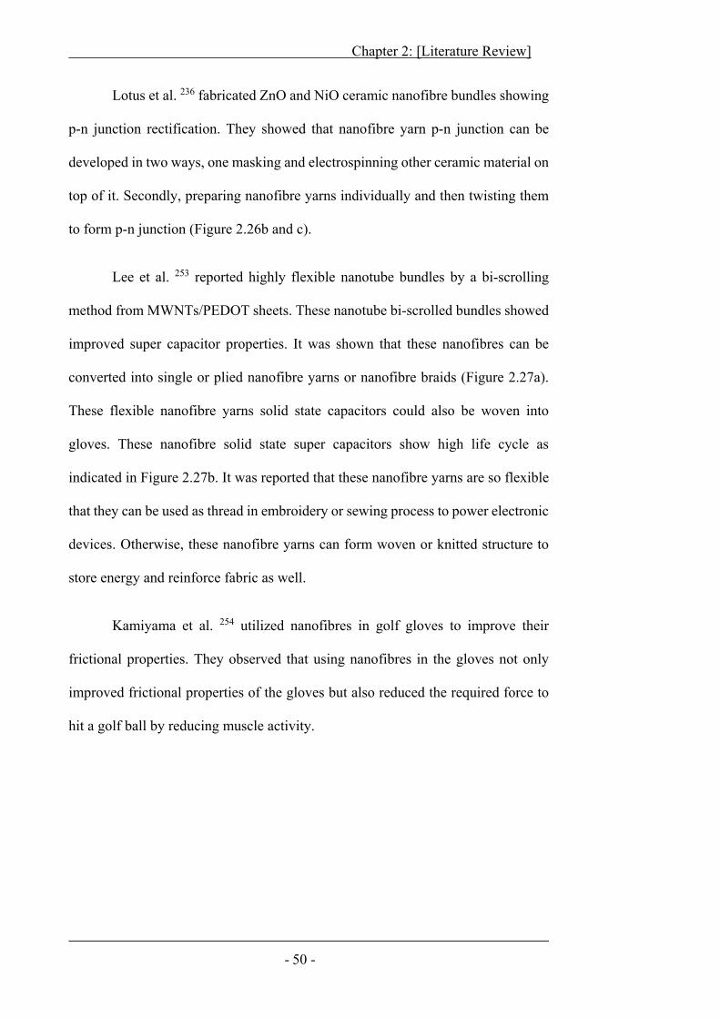
Chapter 2: [Literature Review]
- 50 -
Lotus et al. 236 fabricated ZnO and NiO ceramic nanofibre bundles showing
p-n junction rectification. They showed that nanofibre yarn p-n junction can be
developed in two ways, one masking and electrospinning other ceramic material on
top of it. Secondly, preparing nanofibre yarns individually and then twisting them
to form p-n junction (Figure 2.26b and c).
Lee et al. 253 reported highly flexible nanotube bundles by a bi-scrolling
method from MWNTs/PEDOT sheets. These nanotube bi-scrolled bundles showed
improved super capacitor properties. It was shown that these nanofibres can be
converted into single or plied nanofibre yarns or nanofibre braids (Figure 2.27a).
These flexible nanofibre yarns solid state capacitors could also be woven into
gloves. These nanofibre solid state super capacitors show high life cycle as
indicated in Figure 2.27b. It was reported that these nanofibre yarns are so flexible
that they can be used as thread in embroidery or sewing process to power electronic
devices. Otherwise, these nanofibre yarns can form woven or knitted structure to
store energy and reinforce fabric as well.
Kamiyama et al. 254 utilized nanofibres in golf gloves to improve their
frictional properties. They observed that using nanofibres in the gloves not only
improved frictional properties of the gloves but also reduced the required force to
hit a golf ball by reducing muscle activity.
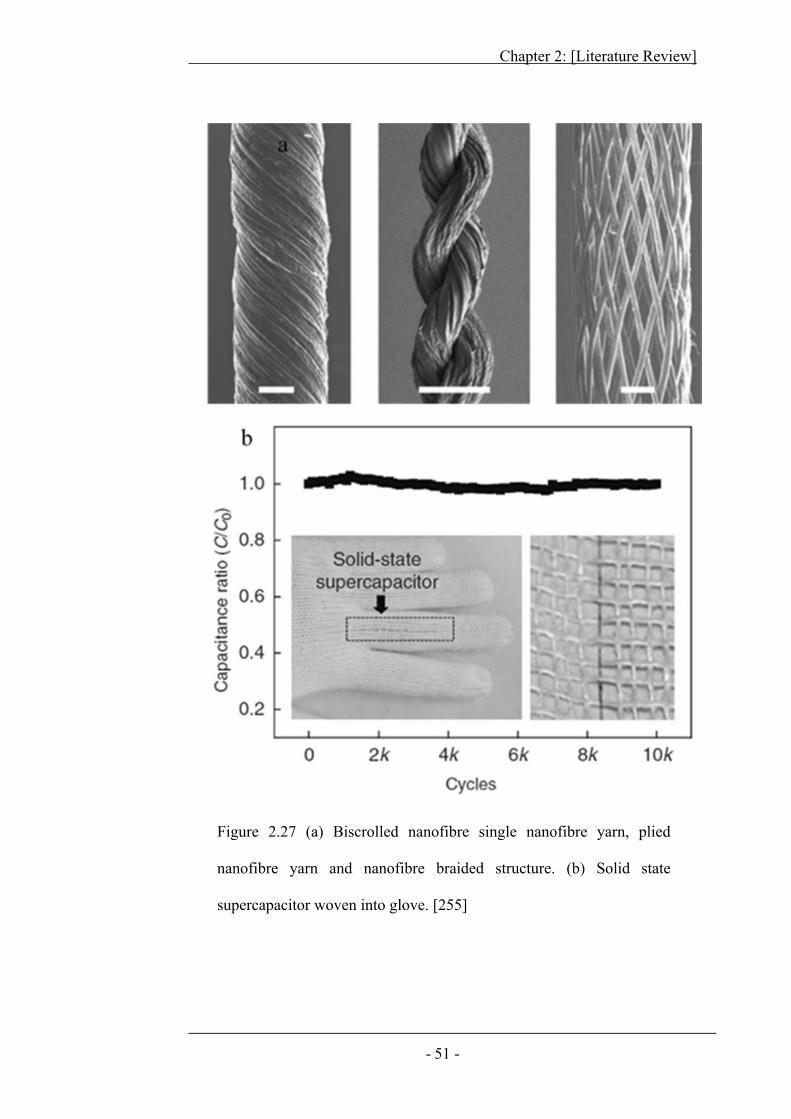
Chapter 2: [Literature Review]
- 51 -
Figure 2.27 (a) Biscrolled nanofibre single nanofibre yarn, plied
nanofibre yarn and nanofibre braided structure. (b) Solid state
supercapacitor woven into glove. [255]
Chapter 2: [Literature Review]
- 52 -
Mirvakili et al. 255 produced niobium (Nb) nanofibre short twisted bundles
using severe plastic deformation (SPD). These bundles possess higher mechanical
strength (0.4 to 1.1 Gpa) almost similar to carbon multi wall nanotube yarns and
showed improved electrical conductivity (3x10⁶ S/m) 100 times that of carbon
multi wall nanotube yarns (3x10⁴ S/m). It was also found that the thermal torsional
actuation of these nanofibre yarns required very low voltage (Figure 2.28). The low
voltage requirement was indicated to be due to high conductivity of Nb (niobium)
nanofibre yarns. These nanofibre yarns were proposed to be good candidate for heat
or electric field activated drug delivery, catheters, toys and miniature valves.
Figure 2.28 (a) A paddle attached to biscrolled yarn to visualize torque in the
nanofibre yarn. (b) Niobium twisted yarn [257].
Chapter 2: [Literature Review]
- 53 -
Khil et al. 242 developed woven structures from electrospun
polycaprolactone (PCL) nanofibre filament yarns for tissue engineered scaffolds
Figure 2.29a. Yao et al. 45 and Ali et al. 251 have also produced woven and knitted
fabrics utilizing nanofibre yarns Figure 2.29 b, c & d. Similarly, 3D fibrous
structures can be developed from nanofibre yarns using well-established fibrous
weaving or knitting technology. The dream of producing human organs in
laboratories might become a reality 8,256-262.
Fabrics produced from nanofibre yarns will be breathable yet lightweight,
robust and more lustrous. Well-defined porosity of fabrics made from nanofibre
yarns can be utilized in filters, protective clothing and wound dressings. The
interconnected pores in nanofibre yarns can assist in wicking and improved dye
ability. Nanofibres have diameter below the wavelength of visible light spectra,
making them transparent in normal light. This unique property can be utilized to
produce transparent protective composite sheets made from nanofibre yarns for
security and defence applications 263.
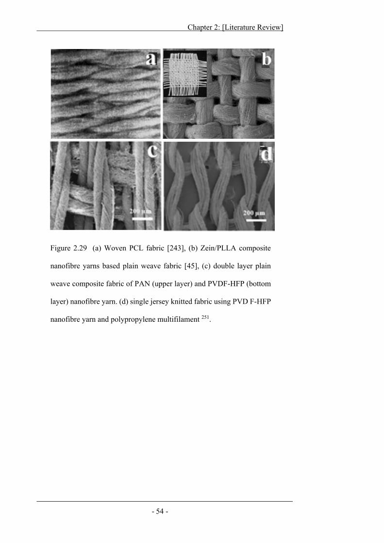
Chapter 2: [Literature Review]
- 54 -
Figure 2.29 (a) Woven PCL fabric [243], (b) Zein/PLLA composite
nanofibre yarns based plain weave fabric [45], (c) double layer plain
weave composite fabric of PAN (upper layer) and PVDF-HFP (bottom
layer) nanofibre yarn. (d) single jersey knitted fabric using PVD F-HFP
nanofibre yarn and polypropylene multifilament 251.
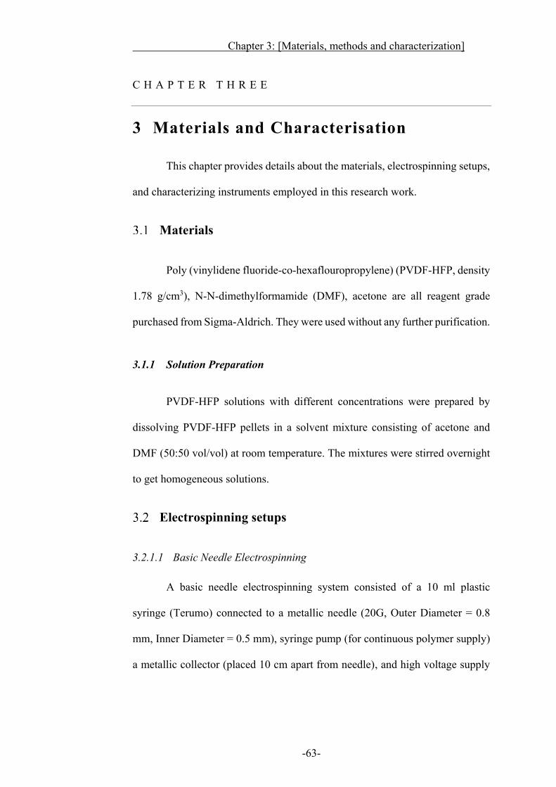
Chapter 3: [Materials, methods and characterization]
-63-
C H A P T E R T H R E E
3 Materials and Characterisation
This chapter provides details about the materials, electrospinning setups,
and characterizing instruments employed in this research work.
Materials
Poly (vinylidene fluoride-co-hexaflouropropylene) (PVDF-HFP, density
1.78 g/cm3), N-N-dimethylformamide (DMF), acetone are all reagent grade
purchased from Sigma-Aldrich. They were used without any further purification.
3.1.1 Solution Preparation
PVDF-HFP solutions with different concentrations were prepared by
dissolving PVDF-HFP pellets in a solvent mixture consisting of acetone and
DMF (50:50 vol/vol) at room temperature. The mixtures were stirred overnight
to get homogeneous solutions.
Electrospinning setups
3.2.1.1 Basic Needle Electrospinning
A basic needle electrospinning system consisted of a 10 ml plastic
syringe (Terumo) connected to a metallic needle (20G, Outer Diameter = 0.8
mm, Inner Diameter = 0.5 mm), syringe pump (for continuous polymer supply)
a metallic collector (placed 10 cm apart from needle), and high voltage supply
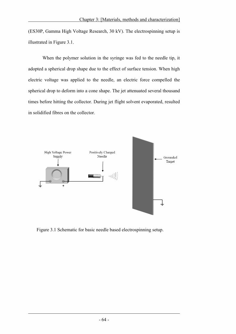
Chapter 3: [Materials, methods and characterization]
- 64 -
(ES30P, Gamma High Voltage Research, 30 kV). The electrospinning setup is
illustrated in Figure 3.1.
When the polymer solution in the syringe was fed to the needle tip, it
adopted a spherical drop shape due to the effect of surface tension. When high
electric voltage was applied to the needle, an electric force compelled the
spherical drop to deform into a cone shape. The jet attenuated several thousand
times before hitting the collector. During jet flight solvent evaporated, resulted
in solidified fibres on the collector.
Figure 3.1 Schematic for basic needle based electrospinning setup.
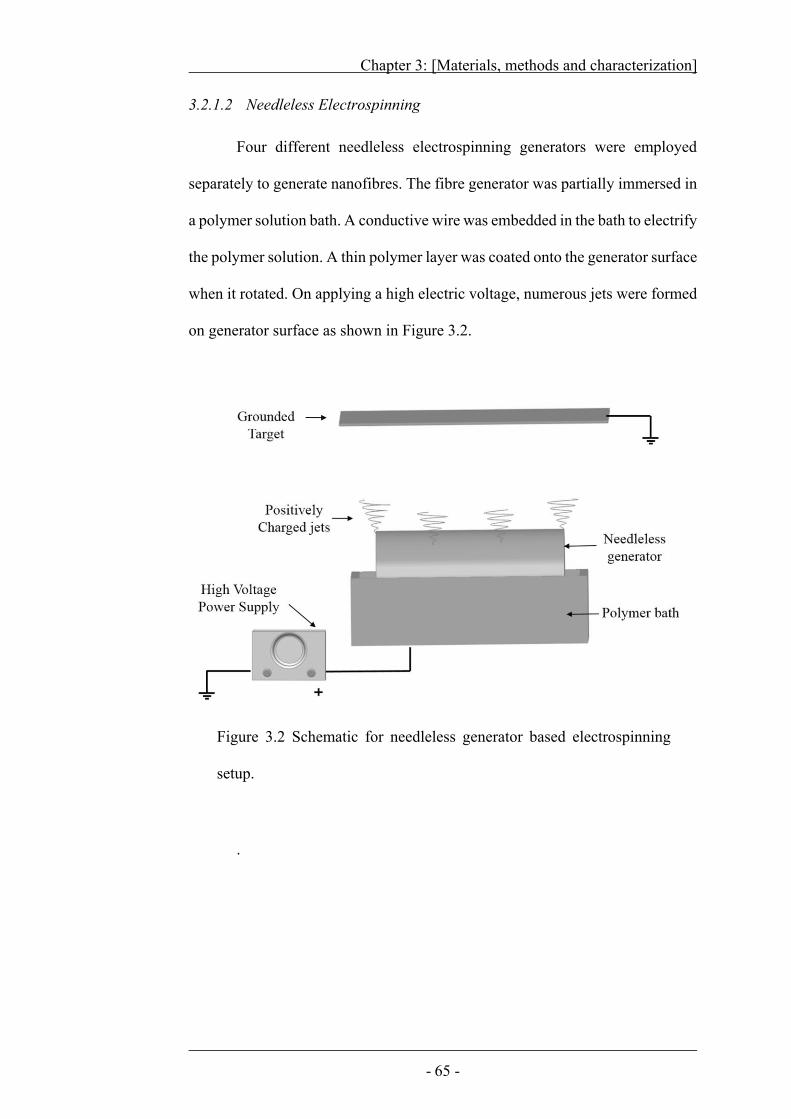
Chapter 3: [Materials, methods and characterization]
- 65 -
3.2.1.2 Needleless Electrospinning
Four different needleless electrospinning generators were employed
separately to generate nanofibres. The fibre generator was partially immersed in
a polymer solution bath. A conductive wire was embedded in the bath to electrify
the polymer solution. A thin polymer layer was coated onto the generator surface
when it rotated. On applying a high electric voltage, numerous jets were formed
on generator surface as shown in Figure 3.2.
.
Figure 3.2 Schematic for needleless generator based electrospinning
setup.
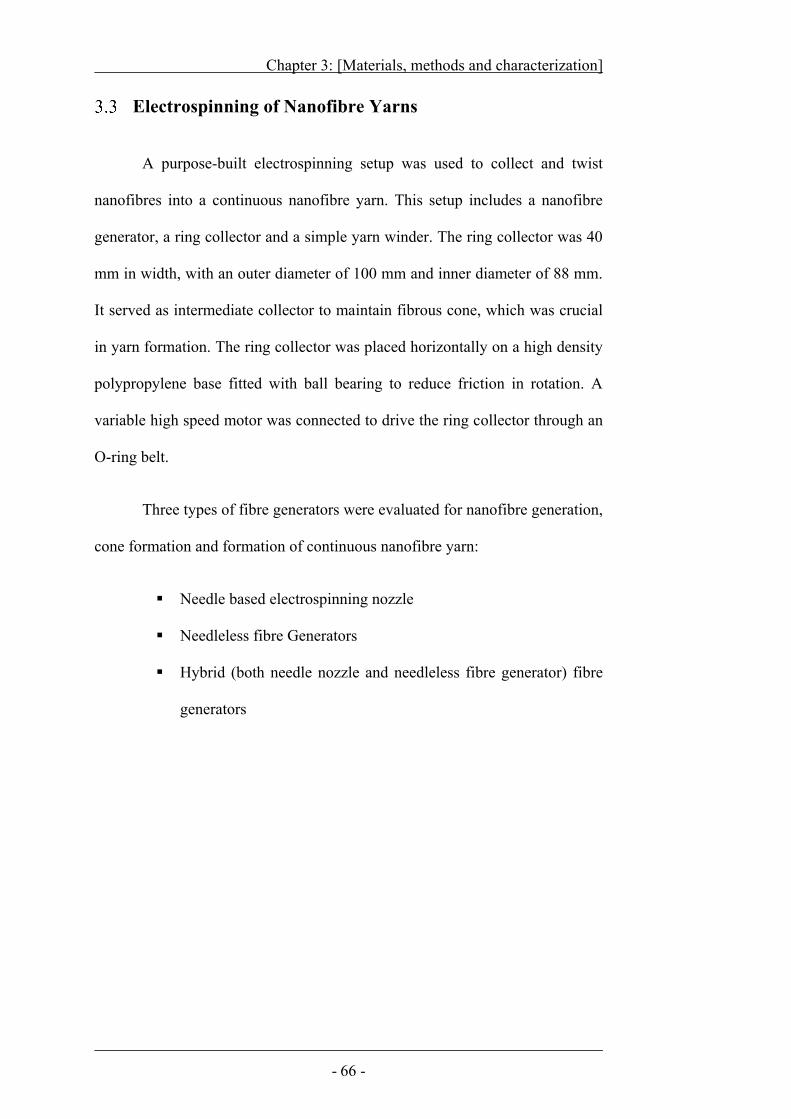
Chapter 3: [Materials, methods and characterization]
- 66 -
Electrospinning of Nanofibre Yarns
A purpose-built electrospinning setup was used to collect and twist
nanofibres into a continuous nanofibre yarn. This setup includes a nanofibre
generator, a ring collector and a simple yarn winder. The ring collector was 40
mm in width, with an outer diameter of 100 mm and inner diameter of 88 mm.
It served as intermediate collector to maintain fibrous cone, which was crucial
in yarn formation. The ring collector was placed horizontally on a high density
polypropylene base fitted with ball bearing to reduce friction in rotation. A
variable high speed motor was connected to drive the ring collector through an
O-ring belt.
Three types of fibre generators were evaluated for nanofibre generation,
cone formation and formation of continuous nanofibre yarn:
Needle based electrospinning nozzle
Needleless fibre Generators
Hybrid (both needle nozzle and needleless fibre generator) fibre
generators
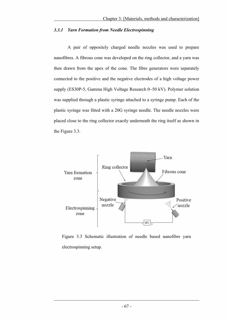
Chapter 3: [Materials, methods and characterization]
- 67 -
3.3.1 Yarn Formation from Needle Electrospinning
A pair of oppositely charged needle nozzles was used to prepare
nanofibres. A fibrous cone was developed on the ring collector, and a yarn was
then drawn from the apex of the cone. The fibre generators were separately
connected to the positive and the negative electrodes of a high voltage power
supply (ES30P-5, Gamma High Voltage Research 0~50 kV). Polymer solution
was supplied through a plastic syringe attached to a syringe pump. Each of the
plastic syringe was fitted with a 20G syringe needle. The needle nozzles were
placed close to the ring collector exactly underneath the ring itself as shown in
the Figure 3.3.
Figure 3.3 Schematic illustration of needle based nanofibre yarn
electrospinning setup.
Chapter 3: [Materials, methods and characterization]
- 68 -
3.3.2 Needleless electrospinning of nanofibre yarn
Needleless fibre generators such as cylinder, circular coil, ring and disc
were used for electrospinning of nanofibre yarns. Each fibre generator was
driven by a motor to vary the rotation speed. A conductive wire was embedded
into the polymer solution to apply high electric voltage to the polymer solution.
The needleless generator was partially immersed in polymer solution.
When it rotated, the polymer solution was loaded over the generator surface
(Figure 3.4). When the generator was rotated too slowly, i.e., 12 rpm, the amount
of polymer was not sufficient to coat entire spinneret surface. In this case, the
polymer solution thickness on the spinneret was not even. At a speed of 20 rpm,
the entire fibre generator was covered with a thin layer of polymer solution on
the surface, and the solution coating was smooth. A speed higher than 30 rpm
resulted in over coating of polymer solution due to drag and generator started
throwing away polymer solution.
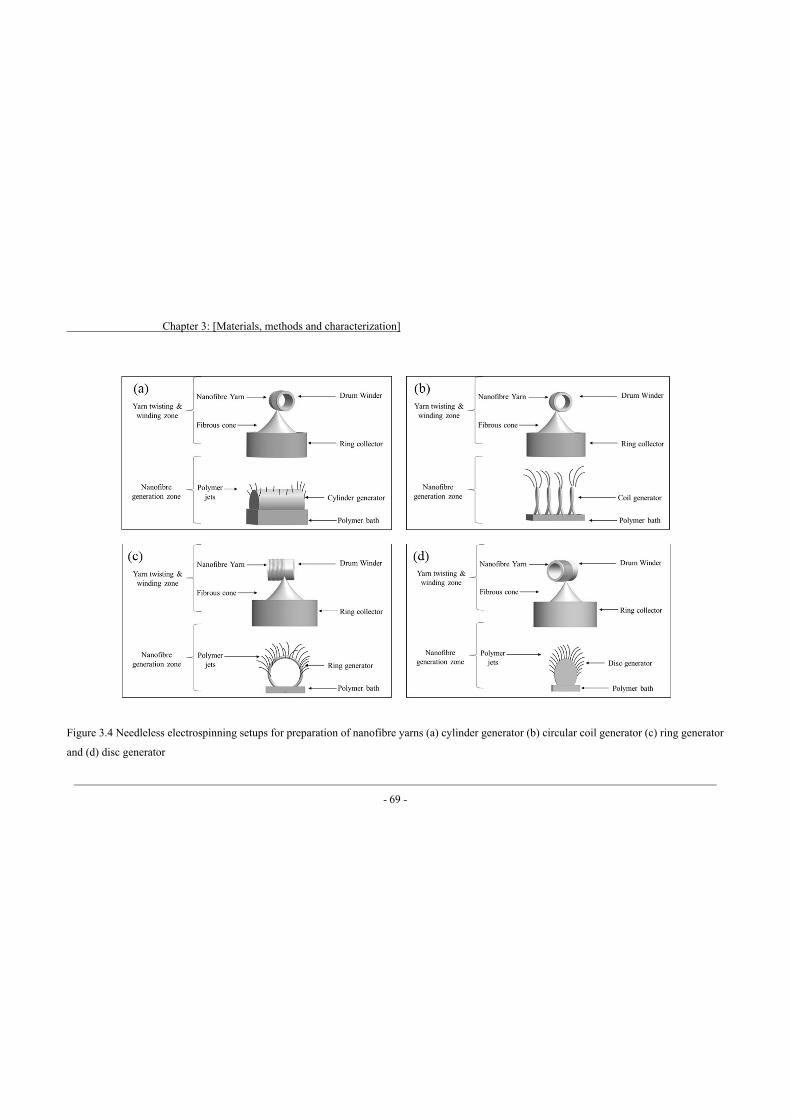
Chapter 3: [Materials, methods and characterization]
- 69 -
Figure 3.4 Needleless electrospinning setups for preparation of nanofibre yarns (a) cylinder generator (b) circular coil generator (c) ring generator
and (d) disc generator
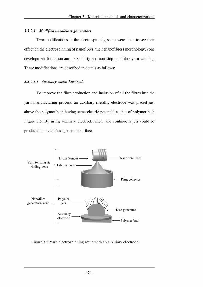
Chapter 3: [Materials, methods and characterization]
- 70 -
3.3.2.1 Modified needleless generators
Two modifications in the electrospinning setup were done to see their
effect on the electrospinning of nanofibres, their (nanofibres) morphology, cone
development formation and its stability and non-stop nanofibre yarn winding.
These modifications are described in details as follows:
3.3.2.1.1 Auxiliary Metal Electrode
To improve the fibre production and inclusion of all the fibres into the
yarn manufacturing process, an auxiliary metallic electrode was placed just
above the polymer bath having same electric potential as that of polymer bath
Figure 3.5. By using auxiliary electrode, more and continuous jets could be
produced on needleless generator surface.
Figure 3.5 Yarn electrospinning setup with an auxiliary electrode.
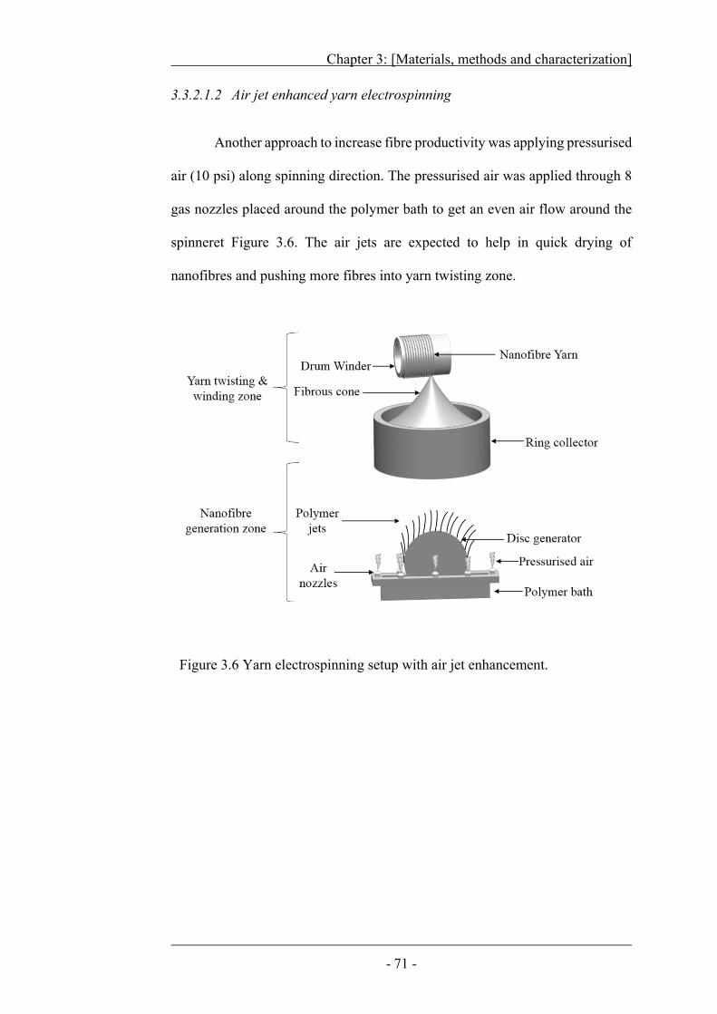
Chapter 3: [Materials, methods and characterization]
- 71 -
3.3.2.1.2 Air jet enhanced yarn electrospinning
Another approach to increase fibre productivity was applying pressurised
air (10 psi) along spinning direction. The pressurised air was applied through 8
gas nozzles placed around the polymer bath to get an even air flow around the
spinneret Figure 3.6. The air jets are expected to help in quick drying of
nanofibres and pushing more fibres into yarn twisting zone.
Figure 3.6 Yarn electrospinning setup with air jet enhancement.
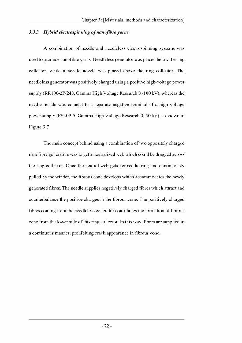
Chapter 3: [Materials, methods and characterization]
- 72 -
3.3.3 Hybrid electrospinning of nanofibre yarns
A combination of needle and needleless electrospinning systems was
used to produce nanofibre yarns. Needleless generator was placed below the ring
collector, while a needle nozzle was placed above the ring collector. The
needleless generator was positively charged using a positive high-voltage power
supply (RR100-2P/240, Gamma High Voltage Research 0~100 kV), whereas the
needle nozzle was connect to a separate negative terminal of a high voltage
power supply (ES30P-5, Gamma High Voltage Research 0~50 kV), as shown in
Figure 3.7
The main concept behind using a combination of two oppositely charged
nanofibre generators was to get a neutralized web which could be dragged across
the ring collector. Once the neutral web gets across the ring and continuously
pulled by the winder, the fibrous cone develops which accommodates the newly
generated fibres. The needle supplies negatively charged fibres which attract and
counterbalance the positive charges in the fibrous cone. The positively charged
fibres coming from the needleless generator contributes the formation of fibrous
cone from the lower side of this ring collector. In this way, fibres are supplied in
a continuous manner, prohibiting crack appearance in fibrous cone.
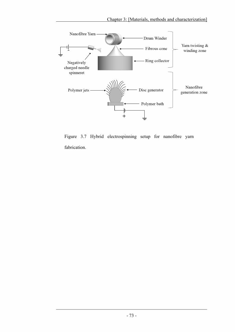
Chapter 3: [Materials, methods and characterization]
- 73 -
Figure 3.7 Hybrid electrospinning setup for nanofibre yarn
fabrication.
Chapter 3: [Materials, methods and characterization]
- 74 -
Finite Element Analysis
Electric field intensity profiles were calculated using a finite element
method with the aid of the COMSOL Multiphysics 3.5a Software in 3D
electrostatic mode. The yarn electrospinning setup (including ring collector, disc
generator, polymer solution and solution bath) were developed in 3D
SolidWorks and transformed into geometrical objects using a bi-interface for
COMSOL. The dimension and relative position of geometrical objects replicated
the real electrospinning setups. The sub-domain settings for relative permittivity
for different materials was set according to the values described in literature
264,265. The relative permittivity for air was set to 1. For polymer solution and
polymer bath, it was 84 and 2, respectively. For conductive disc relative
permittivity was set to -1300, while for non-conductive disc, it was fixed at 2.4.
The voltage boundary conditions were set by applying 50 kV electric potential
to the polymer solution. The voltage for ring collector and the rest of the
boundaries placed at infinity distance was set to V=0, and for remaining interior
boundaries, the condition of continuity n. (D1-D2) = 0 was applied. The
geometries were converted to mesh and calculations were performed in the
COMSOL. The disc with different materials (conductive and non-conductive)
was simulated using this software to evaluate their electric field intensity. The
constitutive relation D = ε0. εr. E was used along with E = - V to obtain the
equation, - .ε0. εr. = dρ. Here “E” represents electric field relative, while “ρ”
and “εr” stand for space charge density and permittivity of air, respectively.
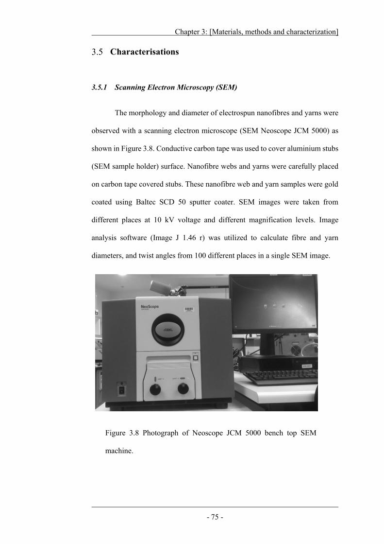
Chapter 3: [Materials, methods and characterization]
- 75 -
Characterisations
3.5.1 Scanning Electron Microscopy (SEM)
The morphology and diameter of electrospun nanofibres and yarns were
observed with a scanning electron microscope (SEM Neoscope JCM 5000) as
shown in Figure 3.8. Conductive carbon tape was used to cover aluminium stubs
(SEM sample holder) surface. Nanofibre webs and yarns were carefully placed
on carbon tape covered stubs. These nanofibre web and yarn samples were gold
coated using Baltec SCD 50 sputter coater. SEM images were taken from
different places at 10 kV voltage and different magnification levels. Image
analysis software (Image J 1.46 r) was utilized to calculate fibre and yarn
diameters, and twist angles from 100 different places in a single SEM image.
Figure 3.8 Photograph of Neoscope JCM 5000 bench top SEM
machine.
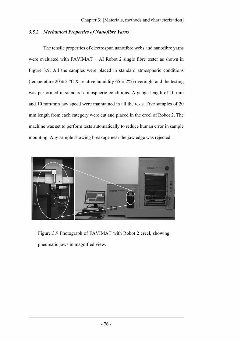
Chapter 3: [Materials, methods and characterization]
- 76 -
3.5.2 Mechanical Properties of Nanofibre Yarns
The tensile properties of electrospun nanofibre webs and nanofibre yarns
were evaluated with FAVIMAT + AI Robot 2 single fibre tester as shown in
Figure 3.9. All the samples were placed in standard atmospheric conditions
(temperature 20 ± 2 °C & relative humidity 65 ± 2%) overnight and the testing
was performed in standard atmospheric conditions. A gauge length of 10 mm
and 10 mm/min jaw speed were maintained in all the tests. Five samples of 20
mm length from each category were cut and placed in the creel of Robot 2. The
machine was set to perform tests automatically to reduce human error in sample
mounting. Any sample showing breakage near the jaw edge was rejected.
Figure 3.9 Photograph of FAVIMAT with Robot 2 creel, showing
pneumatic jaws in magnified view.
- 77-
C H A P T E R F O U R
4 Nanofibre Yarn Prepared by Needle
Electrospinning Systems
In this chapter, a novel electrospinning technique for continuous
electrospinning of nanofibre yarns has been described. A pair of positive and
negative needle generators along with intermediate ring collector and drum
winder were employed to fabricate nanofibre yarns. Nanofibres and their
electrospun yarns were examined under scanning electron microscope (SEM) to
observe their morphologies, diameters, and twist angles. Mechanical properties
of electrospun nanofibre yarns were tested to evaluate improvement in nanofibre
strength in yarn structure. The effect of different twist levels on tensile strength
and strain percentage of yarns thus produced was also investigated.
4.1 Experimental
4.1.1 Electrospinning of Nanofibre Yarn
A purpose-built electrospinning setup was used to prepare nanofibre
yarns, which comprised of two needle-based electrospinning systems, an
aluminium ring collector, and a simple drum winder as schematically illustrated
in Figure 4.1. The ring collector (40 mm in width, outer diameter = 100 mm,
inner diameter = 88 mm) was laid horizontally on a plastic plate fitted with a ball
bearing to reduce friction in rotation. A motor was connected to the ring collector
through an O-ring belt.
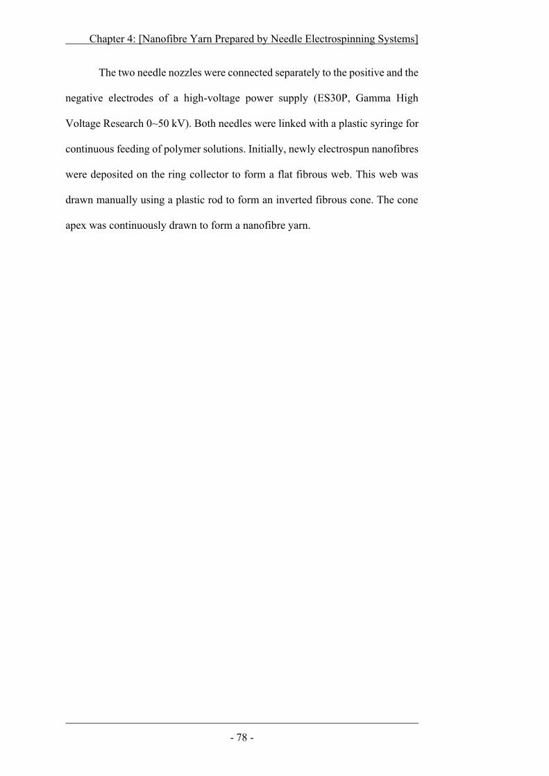
Chapter 4: [Nanofibre Yarn Prepared by Needle Electrospinning Systems]
- 78 -
The two needle nozzles were connected separately to the positive and the
negative electrodes of a high-voltage power supply (ES30P, Gamma High
Voltage Research 0~50 kV). Both needles were linked with a plastic syringe for
continuous feeding of polymer solutions. Initially, newly electrospun nanofibres
were deposited on the ring collector to form a flat fibrous web. This web was
drawn manually using a plastic rod to form an inverted fibrous cone. The cone
apex was continuously drawn to form a nanofibre yarn.
Chapter 4: [Nanofibre Yarn Prepared by Needle Electrospinning Systems]
- 79 -
4.2 Preparation of Twisted Nanofibre Yarns
Figure 4.1a schematically illustrates the setup for electrospinning of
nanofibre yarns. Two electrospinning systems, one positively charged and
another negatively charged, were employed to produce oppositely charged
nanofibres. Initially, when the ring collector was not moving, a fibrous web was
formed by deposition of nanofibres on the inside surface of the ring collector.
As soon as, the ring started rotating, flat web was formed on the periphery of
ring collector. A fibrous cone was then formed through drawing the fibrous web
at the central part along electrospinning direction (Figure 4.1b). By further
drawing nanofibres from the apex of the fibrous cone, a nanofibre yarn resulted,
which was taken up easily by the drum winder. It was noticed that the later-
formed fibres deposited inside the fibrous cone, and the ring collector separated
fibre twisting and yarn collection from electrospinning zone, which is
completely different from previously reported setups46,47,245,249,251,266,267.
Figure 4.1 a) Schematic illustration of yarn electrospinning setup, b)
photograph of fibrous cone formed on ring collector, and c) inset shows
nanofibre yarn collected on a spool.
Chapter 4: [Nanofibre Yarn Prepared by Needle Electrospinning Systems]
- 80 -
Under the scanning electron microscope (SEM) a number of fibres were
observed in the nanofibre yarn collected and all fibres looked uniform and
without binding or fusing with each other. These fibres had an average diameter
around 592 nm. The twist feature was clearly seen on the bundle surface, and the
nanofibres were oriented at an angle 54.4o along the yarn length, typical
characteristics of nanofibre yarns.
The deposition of both positively and negatively charged nanofibres on
the rotary ring collector was essential to form a neutral fibrous cone. To achieve
this, the two electrospinning systems must work simultaneously, and the
threshold voltage to ensure smooth running of both electrospinning systems was
found to be 13 kV. When just one of the nozzle systems worked, though
nanofibres were produced, however, nanofibres either stuck to the ring collector
surface or flew in all directions off the collector and no yarn was formed.
Chapter 4: [Nanofibre Yarn Prepared by Needle Electrospinning Systems]
- 81 -
4.3 Influence of Different Factors on Yarn Electrospinning:
4.3.1 Nozzle location
The nozzle location in the yarn electrospinning setup is an important
factor affecting electrospinning. When the two needle nozzles were placed
equidistant from the ring collector (30 mm), nanofibres produced by the positive
nozzle tended to deposit on the negative nozzle, and this led to end of
electrospinning from the negative nozzle. Thus in this case, only positively
charged nanofibres were produced and they affixed to the ring surface and
consequently yarn fabrication ceased.
Moving the negative nozzle close to the ring collector facilitated
deposition of nanofibres in the central region of the ring collector. In this case,
the negatively charged nanofibres reached middle of the ring collector prior to
positively charged fibres, resulting in charge neutralization of nanofibrous web
in central periphery of the ring collector. In the latter case, the negative and the
positive nozzles were set at 10 mm and 30 mm away from the ring collector,
respectively as shown in Figure 4.2.
Table 4.1 shows yarn electrospinning results for two nozzles locating at
different distances. When the needle nozzles were arranged in style I, no yarn
was formed. Most of the nanofibres deposited just on the inner surface of the
ring collector. This was presumably due to the electrostatic interaction between
the ring and the nanofibres was so strong to retain fibres on the ring surface.
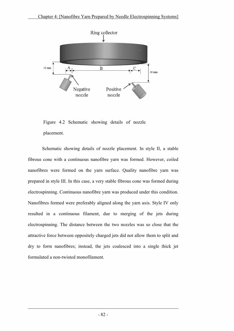
Chapter 4: [Nanofibre Yarn Prepared by Needle Electrospinning Systems]
- 82 -
Figure 4.2 Schematic showing details of nozzle
placement.
Schematic showing details of nozzle placement. In style II, a stable
fibrous cone with a continuous nanofibre yarn was formed. However, coiled
nanofibres were formed on the yarn surface. Quality nanofibre yarn was
prepared in style III. In this case, a very stable fibrous cone was formed during
electrospinning. Continuous nanofibre yarn was produced under this condition.
Nanofibres formed were preferably aligned along the yarn axis. Style IV only
resulted in a continuous filament, due to merging of the jets during
electrospinning. The distance between the two nozzles was so close that the
attractive force between oppositely charged jets did not allow them to split and
dry to form nanofibres; instead, the jets coalesced into a single thick jet
formulated a non-twisted monofilament.
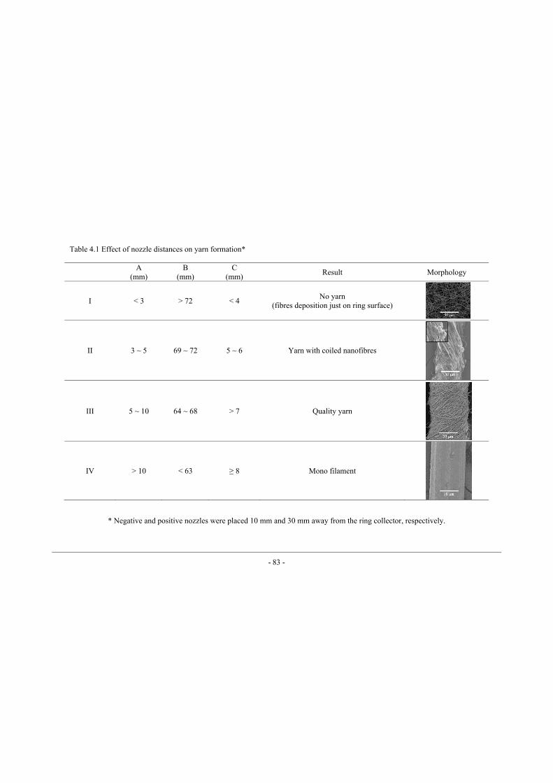
- 83 -
A (mm)
B (mm)
C (mm) Result Morphology
I < 3 > 72 < 4 No yarn (fibres deposition just on ring surface)
II 3 ~ 5 69 ~ 72 5 ~ 6 Yarn with coiled nanofibres
III 5 ~ 10 64 ~ 68 > 7 Quality yarn
IV > 10 < 63 ≥ 8 Mono filament
* Negative and positive nozzles were placed 10 mm and 30 mm away from the ring collector, respectively.
Table 4.1 Effect of nozzle distances on yarn formation*
Chapter 4: [Nanofibre Yarn Prepared by Needle Electrospinning Systems]
- 84 -
4.3.2 Ring collector
The Ring collector is the essential part of this yarn electrospinning setup,
and the rotation of the ring plays a key role in the formation of fibrous cone and
twist in nanofibre yarns. Without rotation, the ring can just collect nanofibres
along the inner surface, and no fibrous cone was formed.
The rotation of the ring collector affected yarn morphology. When ring
speed was below 430 rpm, only a few nanofibres went across the ring collector
without formation of yarn. A continuous fibrous web was formed when the ring
speed was above 500 rpm, but still no yarn was formed. When the speed was
higher than 660 rpm, a steady fibrous cone was generated and a continuous
strand of nanofibre yarn was wound. Nanofibre yarn was prepared without any
interruption when the speed was in the range of 660~1300 rpm. However, when
higher ring speed was employed, 1350 rpm for example, the fibrous cone became
unstable, and yarn breakage often took place.
The ring rotation speed also affected the fibrous cone height, the diameter
of fibre and yarn, and yarn twist feature. With the increase in ring speed from
100 to 430 rpm, the fibre and yarn diameters decreased dramatically (Figure 4.3).
When the ring speed was higher than 660 rpm, increasing the ring speed had no
significant effect on fibre/yarn diameter. Yarn produced at higher ring speed was
more compact and consisted of finer fibres. At 1350 rpm, a very short cone (just
half the produced at 880 rpm) was produced, which was not sufficient enough to
be outstretched into a continuous yarn.
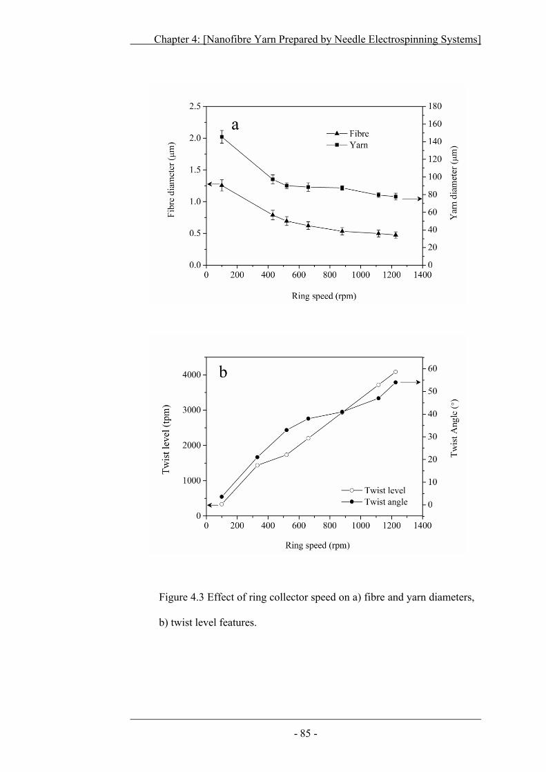
Chapter 4: [Nanofibre Yarn Prepared by Needle Electrospinning Systems]
- 85 -
Figure 4.3 Effect of ring collector speed on a) fibre and yarn diameters,
b) twist level features.
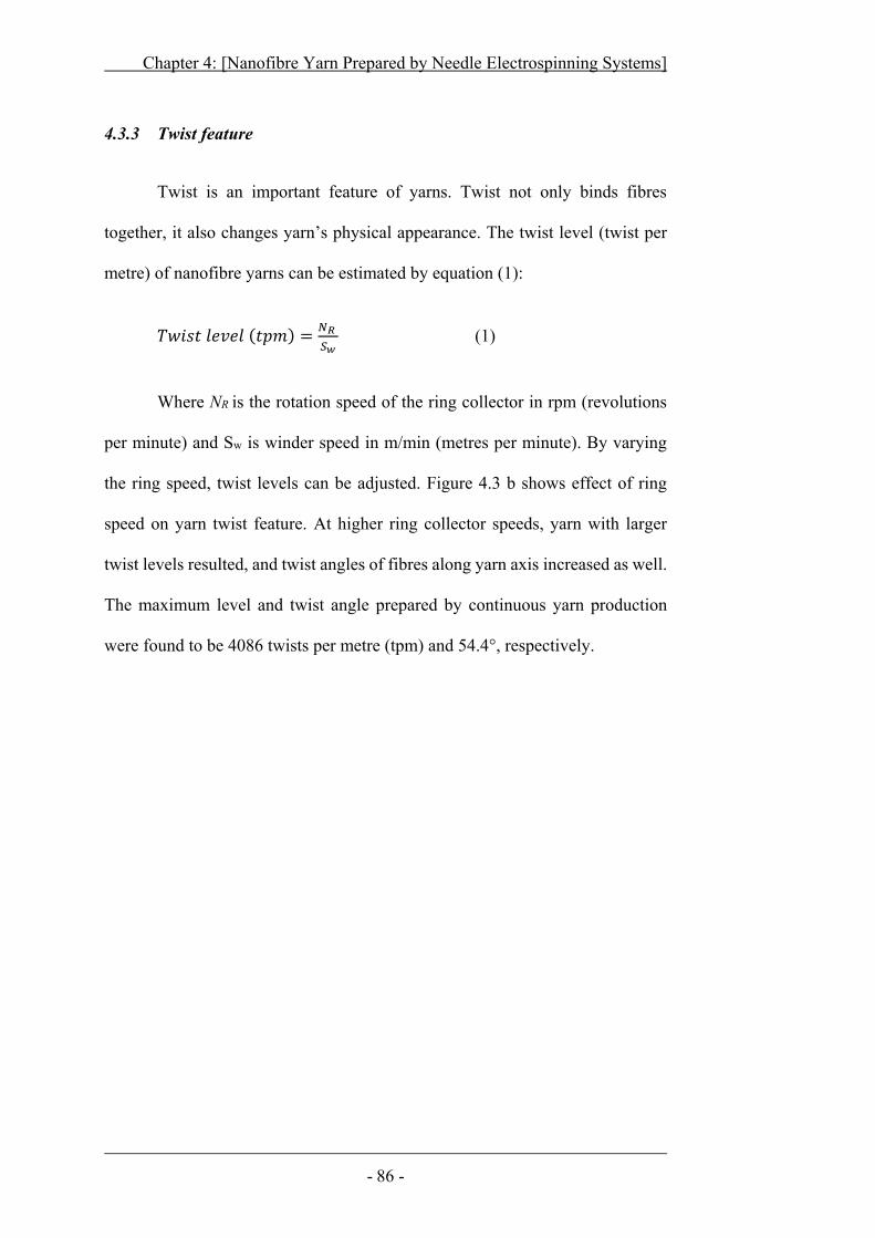
Chapter 4: [Nanofibre Yarn Prepared by Needle Electrospinning Systems]
- 86 -
4.3.3 Twist feature
Twist is an important feature of yarns. Twist not only binds fibres
together, it also changes yarn’s physical appearance. The twist level (twist per
metre) of nanofibre yarns can be estimated by equation (1):
(1)
Where NR is the rotation speed of the ring collector in rpm (revolutions
per minute) and Sw is winder speed in m/min (metres per minute). By varying
the ring speed, twist levels can be adjusted. Figure 4.3 b shows effect of ring
speed on yarn twist feature. At higher ring collector speeds, yarn with larger
twist levels resulted, and twist angles of fibres along yarn axis increased as well.
The maximum level and twist angle prepared by continuous yarn production
were found to be 4086 twists per metre (tpm) and 54.4°, respectively.
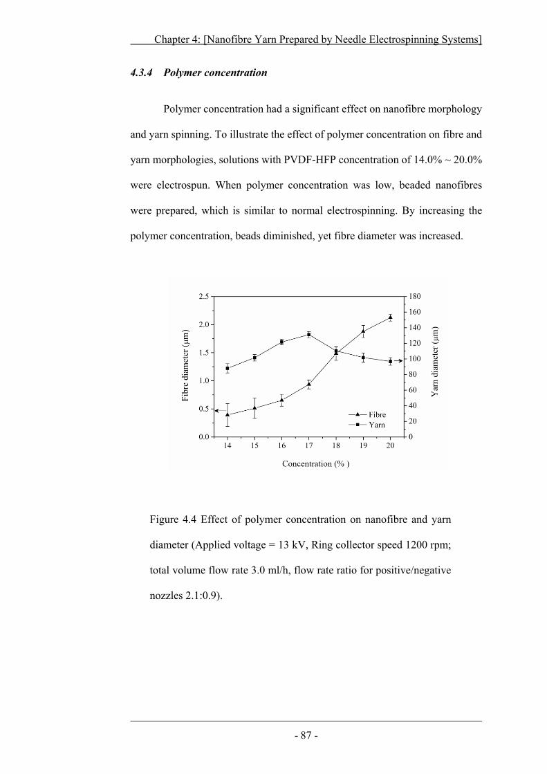
Chapter 4: [Nanofibre Yarn Prepared by Needle Electrospinning Systems]
- 87 -
4.3.4 Polymer concentration
Polymer concentration had a significant effect on nanofibre morphology
and yarn spinning. To illustrate the effect of polymer concentration on fibre and
yarn morphologies, solutions with PVDF-HFP concentration of 14.0% ~ 20.0%
were electrospun. When polymer concentration was low, beaded nanofibres
were prepared, which is similar to normal electrospinning. By increasing the
polymer concentration, beads diminished, yet fibre diameter was increased.
Figure 4.4 Effect of polymer concentration on nanofibre and yarn
diameter (Applied voltage = 13 kV, Ring collector speed 1200 rpm;
total volume flow rate 3.0 ml/h, flow rate ratio for positive/negative
nozzles 2.1:0.9).
Chapter 4: [Nanofibre Yarn Prepared by Needle Electrospinning Systems]
- 88 -
When the concentration was lower than 15.0%, an unstable cone was
formed and continuous yarn could not be collected, while higher polymer
concentration, such as 16.0% and 17.0%, led to a stable cone and continuous
yarn. Further increasing the polymer concentration, e.g. 18.0% ~ 20.0%, resulted
in coarser nanofibres and discontinuous nanofibre yarns
Figure 4.4 shows the effect of polymer concentration on nanofibre and
yarn diameters. Fibre diameter increased by increasing the polymer
concentration. The yarn diameter initially showed an increasing trend when
polymer concentration was gradually increased, while when further increasing
the polymer concentration beyond a certain point, a decline in yarn diameter was
observed. At lower polymer concentration, fibres with entrapped solvent were
produced. Some of fibres stuck on ring collector and remaining fibres went
through ring collector. Cone produced from lesser number and coalescence of
nanofibres resulted in yarn with lower diameter. At higher polymer
concentrations, the solution viscosity increased, fibres produced from such
concentrations were comparatively dry and well separated. These dry and well
separated fibres formed larger diameter yarn. Whereas, further increase in
polymer concentration, presented difficulty in electrospinning process. On such
higher concentrations coarser and fewer nanofibres were produced, thus the
number of fibres going through the ring collector were substantially decreased
and yarn formed showed decrease in diameter.
Table 4.2 summarizes the effect of polymer concentration on threshold
voltages, nanofibre morphology and yarn continuity.
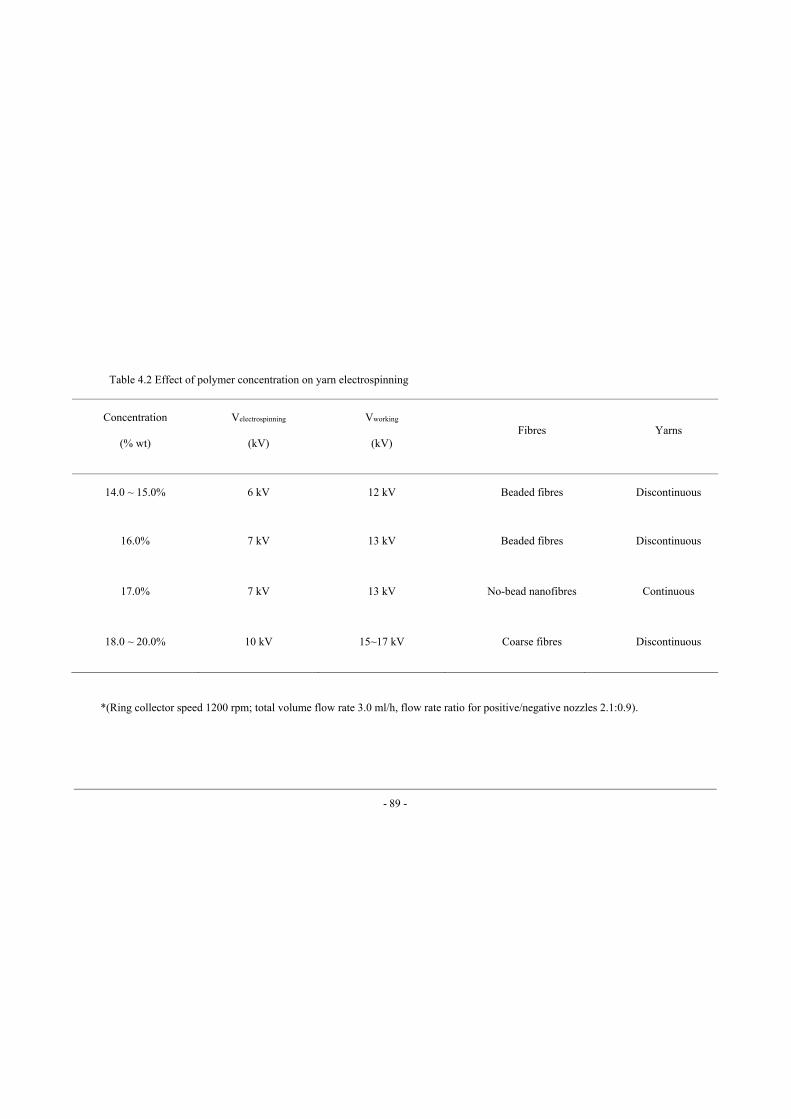
- 89 -
Concentration
(% wt)
Velectrospinning
(kV)
Vworking
(kV)
Fibres Yarns
14.0 ~ 15.0% 6 kV 12 kV Beaded fibres Discontinuous
16.0% 7 kV 13 kV Beaded fibres Discontinuous
17.0% 7 kV 13 kV No-bead nanofibres Continuous
18.0 ~ 20.0% 10 kV 15~17 kV Coarse fibres Discontinuous
*(Ring collector speed 1200 rpm; total volume flow rate 3.0 ml/h, flow rate ratio for positive/negative nozzles 2.1:0.9).
Table 4.2 Effect of polymer concentration on yarn electrospinning
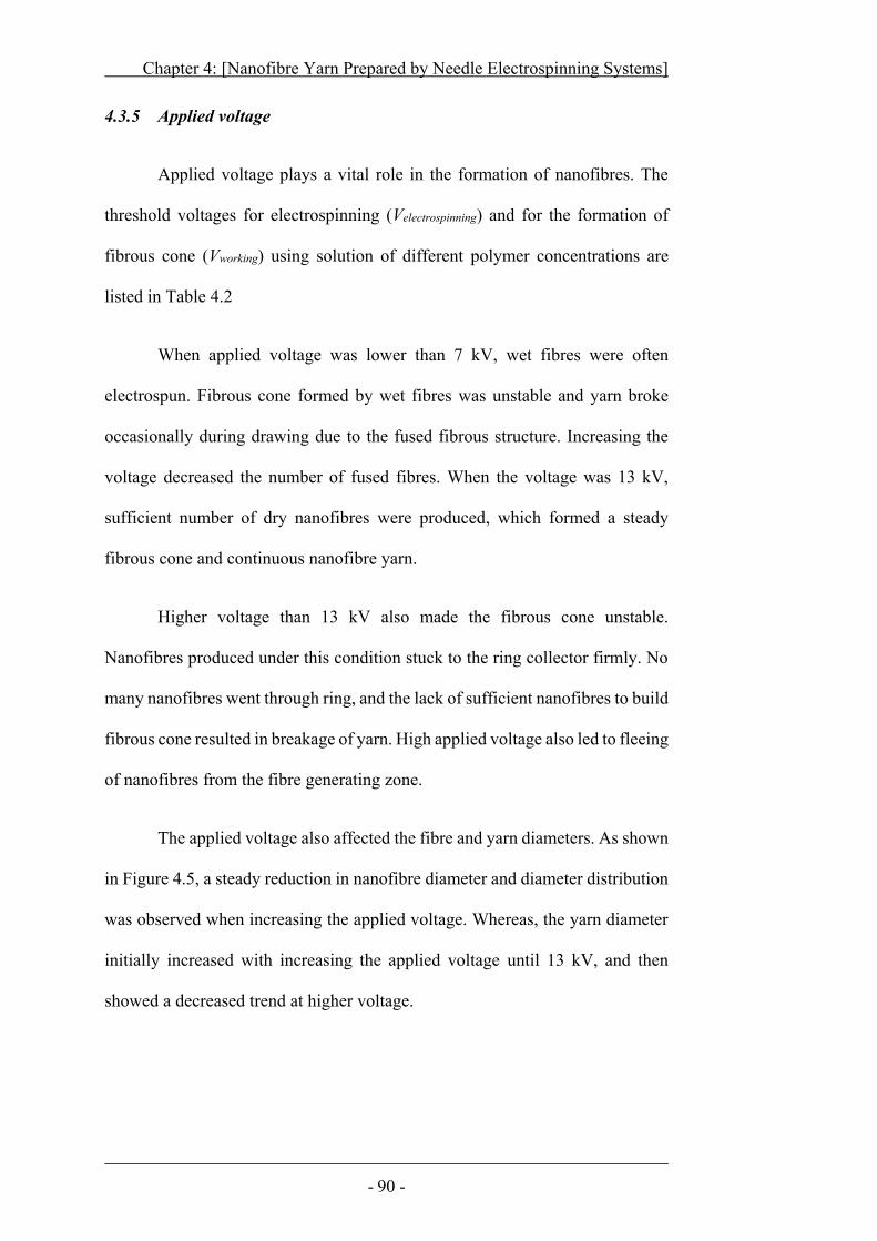
Chapter 4: [Nanofibre Yarn Prepared by Needle Electrospinning Systems]
- 90 -
4.3.5 Applied voltage
Applied voltage plays a vital role in the formation of nanofibres. The
threshold voltages for electrospinning (Velectrospinning) and for the formation of
fibrous cone (Vworking) using solution of different polymer concentrations are
listed in Table 4.2
When applied voltage was lower than 7 kV, wet fibres were often
electrospun. Fibrous cone formed by wet fibres was unstable and yarn broke
occasionally during drawing due to the fused fibrous structure. Increasing the
voltage decreased the number of fused fibres. When the voltage was 13 kV,
sufficient number of dry nanofibres were produced, which formed a steady
fibrous cone and continuous nanofibre yarn.
Higher voltage than 13 kV also made the fibrous cone unstable.
Nanofibres produced under this condition stuck to the ring collector firmly. No
many nanofibres went through ring, and the lack of sufficient nanofibres to build
fibrous cone resulted in breakage of yarn. High applied voltage also led to fleeing
of nanofibres from the fibre generating zone.
The applied voltage also affected the fibre and yarn diameters. As shown
in Figure 4.5, a steady reduction in nanofibre diameter and diameter distribution
was observed when increasing the applied voltage. Whereas, the yarn diameter
initially increased with increasing the applied voltage until 13 kV, and then
showed a decreased trend at higher voltage.
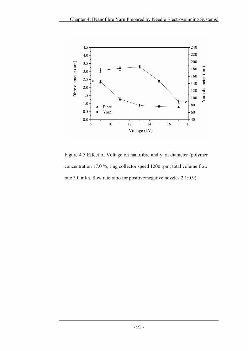
Chapter 4: [Nanofibre Yarn Prepared by Needle Electrospinning Systems]
- 91 -
Figure 4.5 Effect of Voltage on nanofibre and yarn diameter (polymer
concentration 17.0 %, ring collector speed 1200 rpm; total volume flow
rate 3.0 ml/h, flow rate ratio for positive/negative nozzles 2.1:0.9).
Chapter 4: [Nanofibre Yarn Prepared by Needle Electrospinning Systems]
- 92 -
4.3.6 Winding speed
Winding speed was also found to influence the stability of fibrous cone
and nanofibre/yarn diameters. At a winding speed lower than 60 m/h, the fibrous
cone jerked, slackening the yarn, sometimes caused the fibrous cone to break.
When winding speed was higher than 72 m/h, nanofibre yarn was wound with a
proper tension, and a good balance between cone formation and yarn winding
achieved ensuring the continuous withdrawal of nanofibres into yarn. However,
when the winding speed was beyond 200 m/h, vigorous drafting caused cone
breakage.
Figure 4.6 shows the effect of winding speed on nanofibre and yarn
diameters. Increasing the winding speed led to finer nanofibres and yarns. This
can be explained as that nanofibres were stretched at a higher winding speed. In
addition, the winding speed also affected yarn twist feature. When the ring was
kept at a constant speed, increasing the winding speed lowered twist levels in the
yarn. The change in twist can be referred to amount of time spent by yarn
spinning. It took more time in spinning when winding speed was low leading to
larger twist.
Chapter 4: [Nanofibre Yarn Prepared by Needle Electrospinning Systems]
- 93 -
Figure 4.6 Effect of winder speed on nanofibre and yarn diameter,
(polymer concentration 17.0 %, 13kV applied voltage , Ring collector
speed 1200 rpm; total volume flow rate 3.0 ml/h, flow rate ratio for
positive/negative nozzles 2.1:0.9).
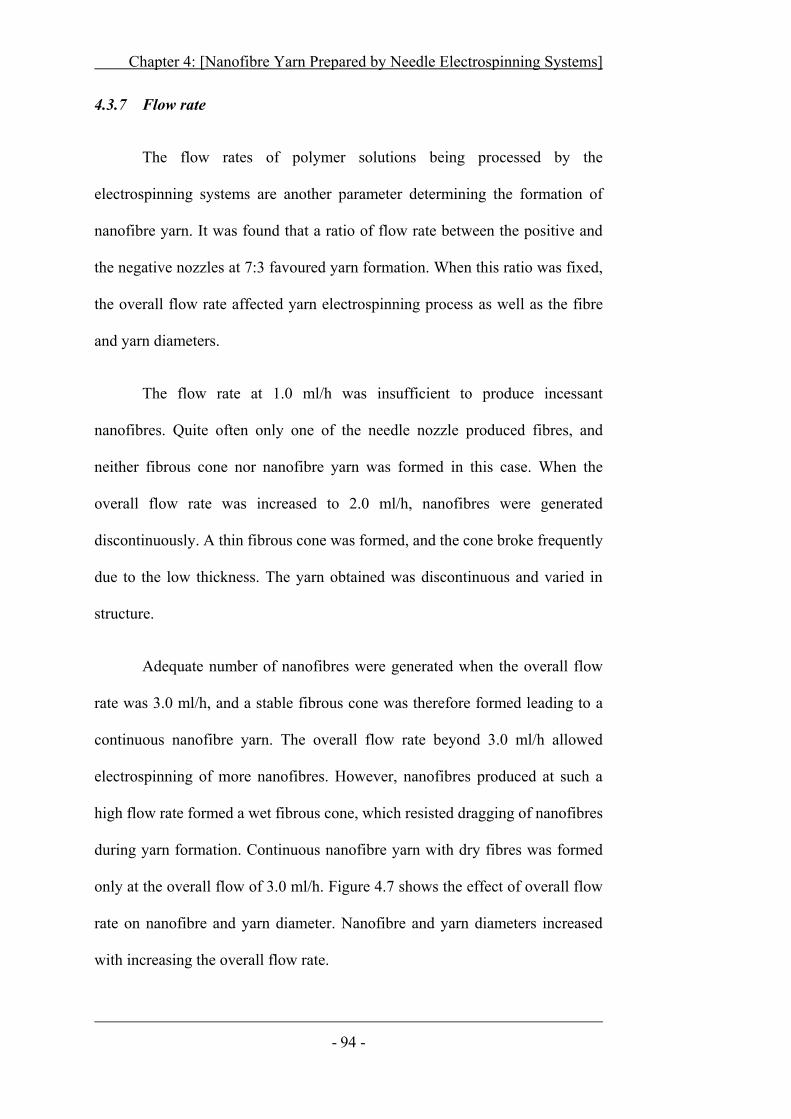
Chapter 4: [Nanofibre Yarn Prepared by Needle Electrospinning Systems]
- 94 -
4.3.7 Flow rate
The flow rates of polymer solutions being processed by the
electrospinning systems are another parameter determining the formation of
nanofibre yarn. It was found that a ratio of flow rate between the positive and
the negative nozzles at 7:3 favoured yarn formation. When this ratio was fixed,
the overall flow rate affected yarn electrospinning process as well as the fibre
and yarn diameters.
The flow rate at 1.0 ml/h was insufficient to produce incessant
nanofibres. Quite often only one of the needle nozzle produced fibres, and
neither fibrous cone nor nanofibre yarn was formed in this case. When the
overall flow rate was increased to 2.0 ml/h, nanofibres were generated
discontinuously. A thin fibrous cone was formed, and the cone broke frequently
due to the low thickness. The yarn obtained was discontinuous and varied in
structure.
Adequate number of nanofibres were generated when the overall flow
rate was 3.0 ml/h, and a stable fibrous cone was therefore formed leading to a
continuous nanofibre yarn. The overall flow rate beyond 3.0 ml/h allowed
electrospinning of more nanofibres. However, nanofibres produced at such a
high flow rate formed a wet fibrous cone, which resisted dragging of nanofibres
during yarn formation. Continuous nanofibre yarn with dry fibres was formed
only at the overall flow of 3.0 ml/h. Figure 4.7 shows the effect of overall flow
rate on nanofibre and yarn diameter. Nanofibre and yarn diameters increased
with increasing the overall flow rate.
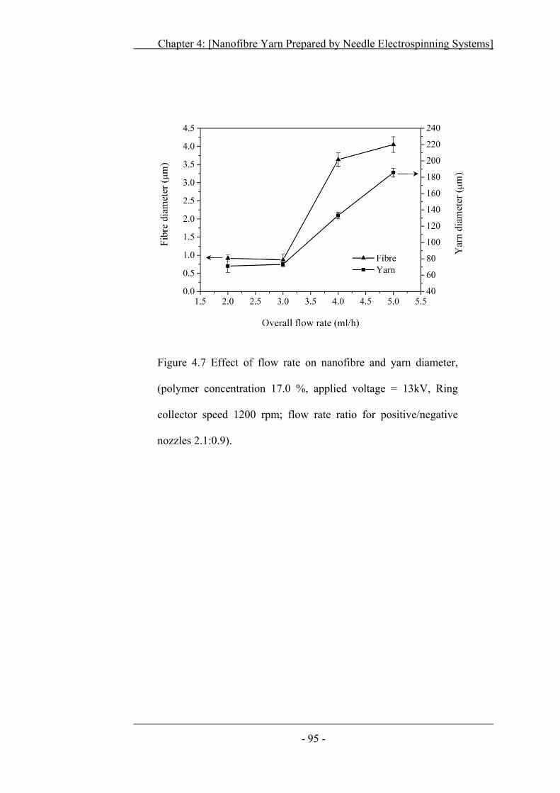
Chapter 4: [Nanofibre Yarn Prepared by Needle Electrospinning Systems]
- 95 -
Figure 4.7 Effect of flow rate on nanofibre and yarn diameter,
(polymer concentration 17.0 %, applied voltage = 13kV, Ring
collector speed 1200 rpm; flow rate ratio for positive/negative
nozzles 2.1:0.9).
Chapter 4: [Nanofibre Yarn Prepared by Needle Electrospinning Systems]
- 96 -
4.4 Mechanical Properties of Nanofibre Yarns:
The mechanical properties of nanofibre yarns were tested on FAVIMAT
(AI) + Robot2. For comparison, random and aligned nanofibre webs fabricated
using conventional electrospinning setup under same electrospinning parameters
were also tested. Nanofibre yarn showed a tensile strength and elongation at
break of 93.6 MPa and 242.6%, respectively. Whereas the randomly-orientated
nanofibre web and aligned nanofibre web showed tensile strength of 9.1 MPa
and 18.5 MPa with elongation at break of 68.3% and 103.8%, respectively
(Figure 4.8a).
Twists in nanofibre yarn helped in binding fibres within yarn and
improved overall fibre to fibre friction. This improved packaging of nanofibres
not only enhanced strength bearing properties of individual fibres but also
improved overall mechanical performance of nanofibre yarns. The tensile
properties were also affected by yarn twist level. As shown in Figure 4.8b, by
increasing the twist level, tensile strength and elongation at break both increased.
It can be anticipated from the fact that at higher the twist levels, higher packaging
of fibres enhanced fibre to fibre contact/friction. At higher twist levels,
individual fibres gained support from neighbouring fibres and showed higher
load bearing capacity with increased strained percentage.
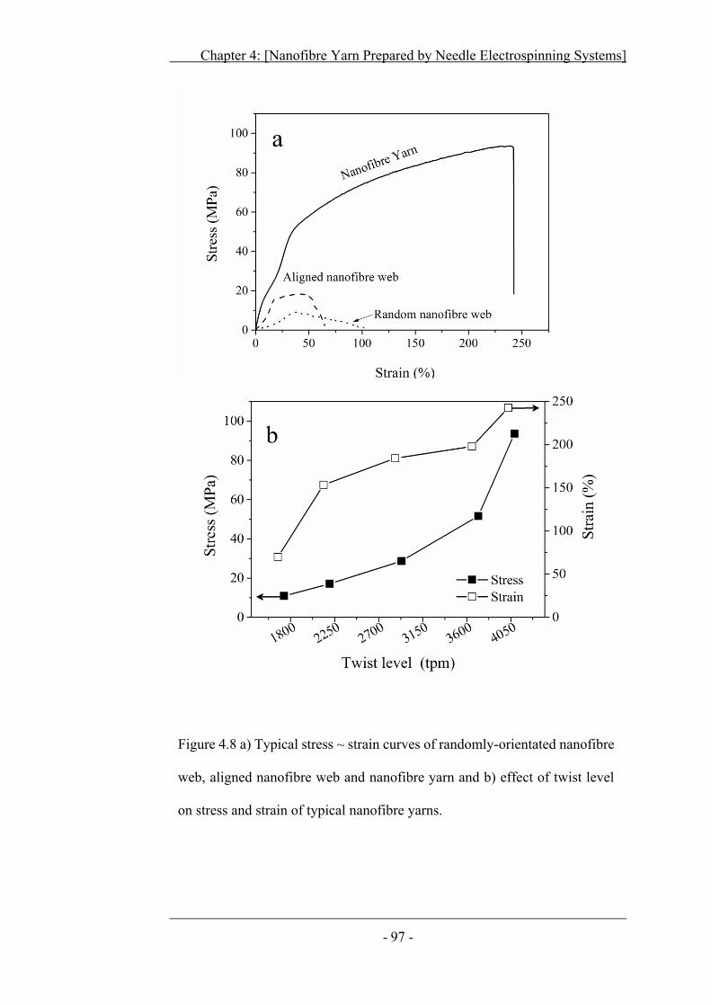
Chapter 4: [Nanofibre Yarn Prepared by Needle Electrospinning Systems]
- 97 -
Figure 4.8 a) Typical stress ~ strain curves of randomly-orientated nanofibre
web, aligned nanofibre web and nanofibre yarn and b) effect of twist level
on stress and strain of typical nanofibre yarns.

Chapter 4: [Nanofibre Yarn Prepared by Needle Electrospinning Systems]
- 98 -
4.5 Conclusion
In this chapter, a novel electrospinning system capable of producing
twisted, continuous nanofibre yarns has been demonstrated. The ring collector
in the system played a key role in formation of fibrous cone and nanofibre yarn.
The ring collector also separated nanofibre generation from yarn
formation/winding zone. By increasing the rotation speed of the ring collector
nanofibre and yarn diameter decreased, whereas twist angle was increased up to
54.4°.
The nozzle location, polymer concentration, applied voltage, flow rate
and winding rate also play roles in the formation of nanofibre yarn and yarn
dimension. The nozzles location was a crucial factor in the manufacturing of
nanofibre yarn. When nozzles were placed closed to ring collector, all the fibres
were deposited on ring surface and no yarn was formed. A coiled fibre yarn was
formulated when nozzles were placed at 69 to 72 mm. A properly dried and
twisted nanofibre yarn was fabricated when nozzle distance was 64 to 68 mm;
whereas, a monofilament yarn was created when nozzles were placed too close
to each other (i.e., less than 63 mm apart).
An increase in polymer concentration and polymer flow rate directly
affected the nanofibre diameter; however, increasing applied voltage, ring
collector and winder speed helped in reducing nanofibre diameter. Yarn
diameter initially increased by increasing polymer concentration and applied
voltage until reaching an optimum value of 17.0 % and 13 kV respectively and
then showed a declining trend. Higher ring collector and winder speeds showed
Chapter 4: [Nanofibre Yarn Prepared by Needle Electrospinning Systems]
- 99 -
a continuous decrease in yarn diameter, whereas larger polymer flow rates
produced coarser yarns. Ring collector and winder speed also directly affected
twist levels in nanofibre yarns. Higher twists could be obtained by keeping
winder speed constant and increasing the ring speed up to 1200 rpm beyond that
it was difficult to properly formulate fibrous cone and thus discontinuous
nanofibre yarn was obtained.
The nanofibre yarn showed much higher tensile strength and elongation
at break (93.6 MPa and elongation of 242.6%) than both aligned and randomly
orientated nanofibre webs (9.1 MPa and 18.5 MPa with elongation at break of
68.3% and 103.8%, respectively). Twist factor in nanofibre yarns also showed
direct influence on yarn strength and strain percentage. Higher twists in
nanofibre yarns helped in nanofibres compaction within yarn. This compaction
and increased fibre to fibre friction facilitated in achieving higher tensile strength
with increased strain percentage.
- 100 -
C H A P T E R F I V E
5 Needleless Electrospinning of Nanofibre
Yarns
In this chapter, four different nanofibre generators (i.e., cylinder, coil,
ring and disc) were used in combination with a transient ring collector and a
simple drum winder to prepare nanofibre yarns. The effect of the fibre generators
on nanofibres generation, morphology and yarn formation was examined.
5.1 Electrospinning of Nanofibres and Nanofibre Yarns
A stationary collector plate covered with aluminium foil was employed
to collect nanofibres during needleless electrospinning. The needleless
generators were immersed in a polymer bath solution, and the slow rotation of
the generators loaded polymer solution uniformly on the generator surface to
coat a uniform polymer layer on spinneret surface. A conductive wire was
embedded in the bottom of polymer solution bath. Electric field was applied to
the polymer solution through this conductive wire. On applying high electric
voltage to polymer solution and rotating the needleless generator, polymer jets
were formed on the fibre generator surface. These jets attenuated and deposited
on stationary collector plate. To properly electrospin nanofibres, needleless fibre
generator was placed at a distance of 60 mm; voltage was changed from 0 kV to
65 kV, and polymer concentration was varied from 9.0 % to 19.0%.
A novel electrospinning system comprising of a needleless generator, a
transient ring collector and a winder system was utilized to electrospin nanofibre
yarn, and the effect of nanofibre generators on yarn formation was evaluated.
Chapter 5: [Needleless Electrospinning of Nanofibre Yarns]
- 101 -
5.2 Needleless Electrospinning of Nanofibres
5.2.1 Cylinder Generator
Needleless electrospinning using cylinder as nanofibre generator has
already established by Elmarco Co. and many other researchers. A cylinder of
70 mm width and 50 mm diameter was used to produce nanofibres. Cylinder was
slowly rotated at a speed of 20 revolution per minute (rpm) in polymer bath to
evenly coat polymer over the cylinder surface. When high electric voltage was
applied, perturbations started appearing on cylinder surface mainly over cylinder
edges. At polymer concentrations lower than 13.0 %, jets could be seen even as
low voltage as 30 kV but these jets produced wet nanofibres and forming a film
instead of fibrous web.
When polymer concentration was 15.0 %, no jets were observed, unless
the electric voltage was above 37 kV (Table 5.1). Initially at this voltage, jets
appeared only from the cylinder edges; while flat part of cylinder showed no jet
formation. When electric voltage was increased up to 45 kV jets were randomly
formed from flat part. At 58 kV, nanofibres could be produced from overall
cylinder surface still, more jets were formed on cylinder edges. The average fibre
diameter was 1.147 μm, with a large variation in diameter ranging from 4.589
μm to 123 nm (Figure 5.1). Whereas at concentrations higher than 17.0 %,
threshold voltage increased to 47 kV, yet number of jets decreased and fibre
formation was greatly reduced from cylinder generator.
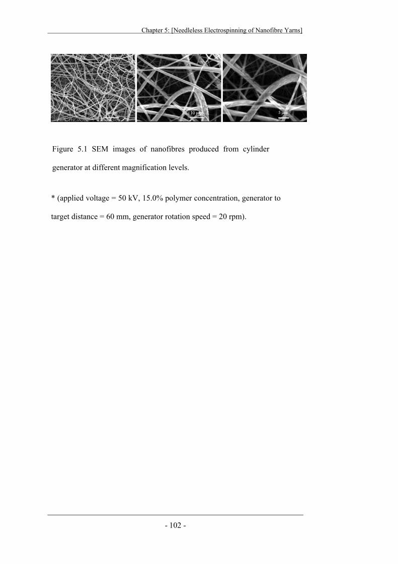
Chapter 5: [Needleless Electrospinning of Nanofibre Yarns]
- 102 -
Figure 5.1 SEM images of nanofibres produced from cylinder
generator at different magnification levels.
* (applied voltage = 50 kV, 15.0% polymer concentration, generator to
target distance = 60 mm, generator rotation speed = 20 rpm).
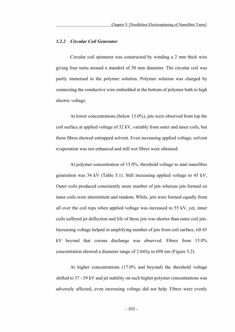
Chapter 5: [Needleless Electrospinning of Nanofibre Yarns]
- 103 -
5.2.2 Circular Coil Generator
Circular coil spinneret was constructed by winding a 2 mm thick wire
giving four turns around a mandrel of 50 mm diameter. The circular coil was
partly immersed in the polymer solution. Polymer solution was charged by
connecting the conductive wire embedded at the bottom of polymer bath to high
electric voltage.
At lower concentrations (below 13.0%), jets were observed from top the
coil surface at applied voltage of 32 kV, variably from outer and inner coils, but
these fibres showed entrapped solvent. Even increasing applied voltage, solvent
evaporation was not enhanced and still wet fibres were obtained.
At polymer concentration of 15.0%, threshold voltage to start nanofibre
generation was 34 kV (Table 5.1). Still increasing applied voltage to 45 kV,
Outer coils produced consistently more number of jets whereas jets formed on
inner coils were intermittent and random. While, jets were formed equally from
all over the coil tops when applied voltage was increased to 55 kV, yet, inner
coils suffered jet deflection and life of these jets was shorter than outer coil jets.
Increasing voltage helped in amplifying number of jets from coil surface, till 65
kV beyond that corona discharge was observed. Fibres from 15.0%
concentration showed a diameter range of 2.645μ to 698 nm (Figure 5.2).
At higher concentrations (17.0% and beyond) the threshold voltage
shifted to 37 ~39 kV and jet stability on such higher polymer concentrations was
adversely affected, even increasing voltage did not help. Fibres were evenly
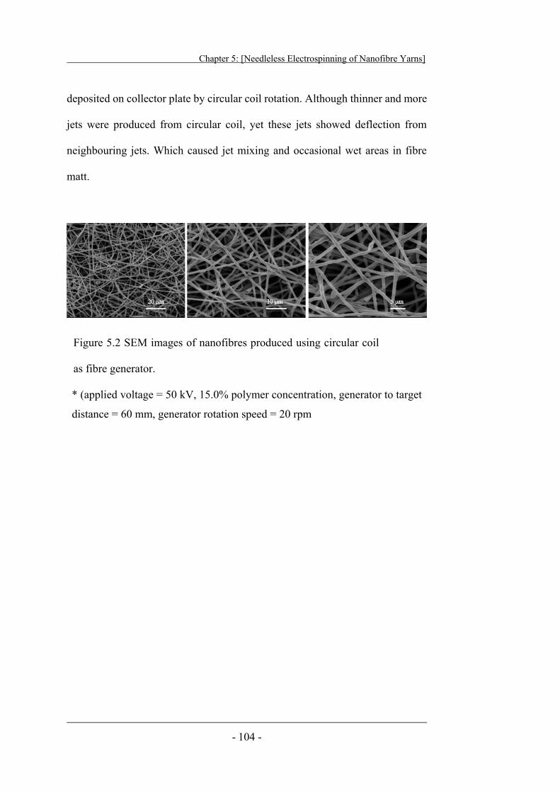
Chapter 5: [Needleless Electrospinning of Nanofibre Yarns]
- 104 -
deposited on collector plate by circular coil rotation. Although thinner and more
jets were produced from circular coil, yet these jets showed deflection from
neighbouring jets. Which caused jet mixing and occasional wet areas in fibre
matt.
Figure 5.2 SEM images of nanofibres produced using circular coil
as fibre generator.
* (applied voltage = 50 kV, 15.0% polymer concentration, generator to target
distance = 60 mm, generator rotation speed = 20 rpm
Chapter 5: [Needleless Electrospinning of Nanofibre Yarns]
- 105 -
5.2.3 Ring Generator
A 2 mm thick wire was folded around 50 mm mandrel to form a round
ring collector. On applying electric field, at lower concentrations (> 13.0%) ring
surface showed jet formation at low electric field i.e., 28 kV; moreover, jets were
produced from overall outer periphery of ring spinneret. Jets were also observed
to emerge from inner ring surface and interfered with jets from outer ring
surface.
The lower concentrations (≥ 13.0%) showed huge number of nanofibres
emerging from disc top at 27 kV, but similar to other generators, the fibres from
such lower concentrations were wet and fused. As described in Table 5.1, the
threshold voltage for 15.0% polymer concentration was greatly reduced to 31
kV. Numerous jets appeared on ring surface at an applied voltage of 49 kV. Fibre
diameter in web from 15.0% varied from very fine nanofibres 184 nm to 1.039
μm coarse fibres as shown in Figure 5.3.
The higher polymer concentrations (17.0 % ≤) it was difficult to produce
jets and nanofibres from ring surface. The jet interference influenced jet stability.
Jet positions variably moved from one place to another on ring surface.
Occasionally, partially, interconnected and wet nanofibres were observed in the
final nanofibre web.
Chapter 5: [Needleless Electrospinning of Nanofibre Yarns]
- 106 -
Figure 5.3 SEM images for nanofibres generated by ring generator
at different magnification levels.
*(applied voltage = 50 kV, 15.0% polymer concentration, generator
to target distance = 60 mm, generator rotation speed = 20 rpm).
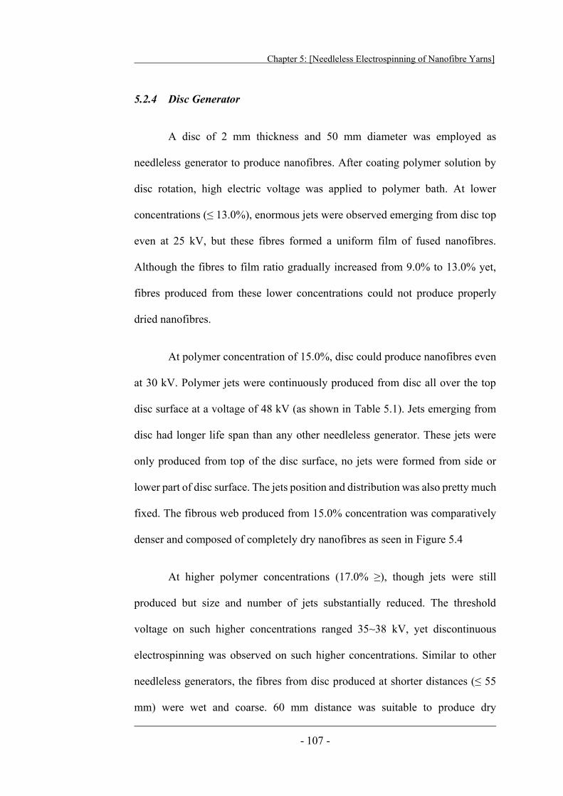
Chapter 5: [Needleless Electrospinning of Nanofibre Yarns]
- 107 -
5.2.4 Disc Generator
A disc of 2 mm thickness and 50 mm diameter was employed as
needleless generator to produce nanofibres. After coating polymer solution by
disc rotation, high electric voltage was applied to polymer bath. At lower
concentrations (≤ 13.0%), enormous jets were observed emerging from disc top
even at 25 kV, but these fibres formed a uniform film of fused nanofibres.
Although the fibres to film ratio gradually increased from 9.0% to 13.0% yet,
fibres produced from these lower concentrations could not produce properly
dried nanofibres.
At polymer concentration of 15.0%, disc could produce nanofibres even
at 30 kV. Polymer jets were continuously produced from disc all over the top
disc surface at a voltage of 48 kV (as shown in Table 5.1). Jets emerging from
disc had longer life span than any other needleless generator. These jets were
only produced from top of the disc surface, no jets were formed from side or
lower part of disc surface. The jets position and distribution was also pretty much
fixed. The fibrous web produced from 15.0% concentration was comparatively
denser and composed of completely dry nanofibres as seen in Figure 5.4
At higher polymer concentrations (17.0% ≥), though jets were still
produced but size and number of jets substantially reduced. The threshold
voltage on such higher concentrations ranged 35~38 kV, yet discontinuous
electrospinning was observed on such higher concentrations. Similar to other
needleless generators, the fibres from disc produced at shorter distances (≤ 55
mm) were wet and coarse. 60 mm distance was suitable to produce dry
Chapter 5: [Needleless Electrospinning of Nanofibre Yarns]
- 108 -
nanofibres, whereas higher electrospinning distance (65 mm ≥) affected fibre
deposition over ring collector.
Figure 5.4 SEM images for nanofibres produced by disc generator.
*(applied voltage = 50 kV, 15.0% polymer concentration, generator
to target distance = 60 mm, generator rotation speed = 20 rpm).
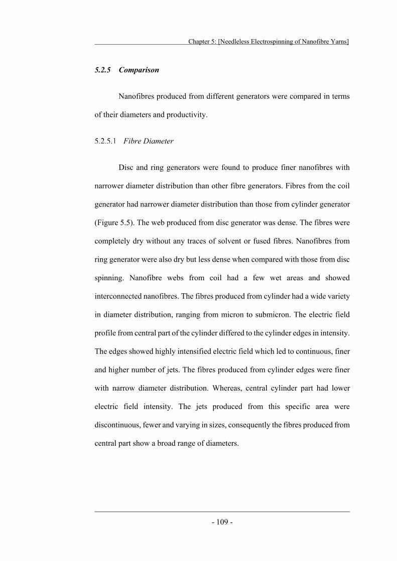
Chapter 5: [Needleless Electrospinning of Nanofibre Yarns]
- 109 -
5.2.5 Comparison
Nanofibres produced from different generators were compared in terms
of their diameters and productivity.
Fibre Diameter
Disc and ring generators were found to produce finer nanofibres with
narrower diameter distribution than other fibre generators. Fibres from the coil
generator had narrower diameter distribution than those from cylinder generator
(Figure 5.5). The web produced from disc generator was dense. The fibres were
completely dry without any traces of solvent or fused fibres. Nanofibres from
ring generator were also dry but less dense when compared with those from disc
spinning. Nanofibre webs from coil had a few wet areas and showed
interconnected nanofibres. The fibres produced from cylinder had a wide variety
in diameter distribution, ranging from micron to submicron. The electric field
profile from central part of the cylinder differed to the cylinder edges in intensity.
The edges showed highly intensified electric field which led to continuous, finer
and higher number of jets. The fibres produced from cylinder edges were finer
with narrow diameter distribution. Whereas, central cylinder part had lower
electric field intensity. The jets produced from this specific area were
discontinuous, fewer and varying in sizes, consequently the fibres produced from
central part show a broad range of diameters.
Chapter 5: [Needleless Electrospinning of Nanofibre Yarns]
- 110 -
Figure 5.5 Effect of generator geometry on fibre diameter.
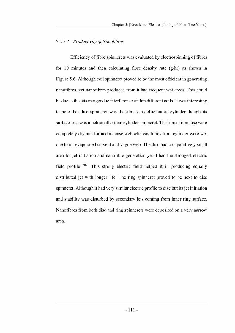
Chapter 5: [Needleless Electrospinning of Nanofibre Yarns]
- 111 -
Productivity of Nanofibres
Efficiency of fibre spinnerets was evaluated by electrospinning of fibres
for 10 minutes and then calculating fibre density rate (g/hr) as shown in
Figure 5.6. Although coil spinneret proved to be the most efficient in generating
nanofibres, yet nanofibres produced from it had frequent wet areas. This could
be due to the jets merger due interference within different coils. It was interesting
to note that disc spinneret was the almost as efficient as cylinder though its
surface area was much smaller than cylinder spinneret. The fibres from disc were
completely dry and formed a dense web whereas fibres from cylinder were wet
due to un-evaporated solvent and vague web. The disc had comparatively small
area for jet initiation and nanofibre generation yet it had the strongest electric
field profile 207. This strong electric field helped it in producing equally
distributed jet with longer life. The ring spinneret proved to be next to disc
spinneret. Although it had very similar electric profile to disc but its jet initiation
and stability was disturbed by secondary jets coming from inner ring surface.
Nanofibres from both disc and ring spinnerets were deposited on a very narrow
area.
Chapter 5: [Needleless Electrospinning of Nanofibre Yarns]
- 112 -
Figure 5.6 Effect of generator geometry on nanofibre
productivity.
Chapter 5: [Needleless Electrospinning of Nanofibre Yarns]
- 113 -
5.3 Needleless Electrospinning of Nanofibre Yarns
The novel ring was used as transient collector to evaluate different
needleless generators for formation of fibrous cone and yarn manufacturing. The
needleless generators were partially immersed in a polymer bath embedded with
a conductive wire. The wire was connected to a high electric voltage power
supply (Gamma High Voltage Research RR100-2P/240, 0 ~ 100 kV).
Polymer concentration for electrospinning of nanofibre yarn was fixed to
15.0%, as fibres generated from all the needleless generators showed good
electrospinning at this concentration. When needleless generator was slowly
rotated (20 rpm) in polymer bath, a thin polymer film was coated on it. On
applying voltage, the polymer solution was charged; a number of jets were
produced and fibres were deposited on ring collector. A web was formed on ring
opening and it was manually dragged to other side of ring. On transferring the
web to a simple drum winder, the fibrous web adopted a conical shape. The ring
rotation imparted twist in the web to form twisted nanofibre yarn. The freshly
generated fibres were deposited on inner fibrous cone. In this way, a continuous
nanofibre yarn was produced.
Chapter 5: [Needleless Electrospinning of Nanofibre Yarns]
- 114 -
5.3.1 Cylinder Generator
The cylinder was used for electrospinning nanofibres to formulate
fibrous cone and yarn (Figure 5.7). The nanofibres were variably produced from
centre and edge of cylinder. The jets varied greatly in shape and size from both
areas. Although the jets from outer cylinder area had longer life, they were
mostly diverted away from target. The jets emerging from central cylinder part
were few and did not last longer. The fibres from this part were generally focused
towards ring collector, but their production was intermittent. The web formed on
the ring opening was not uniform and showed wet areas. On dragging this web
to other side, most of the fibres stuck to ring collector. It was very difficult to
form a fibrous cone. The reason for discontinuous fibrous cone could be due to
the lack of fibres and inclusion of wet fibres.
Distance between cylinder and ring collector was varied between 30 mm
to 70 mm to see its effect on nanofibres and yarn formation. At lower distance
(≤ 45 mm) wet fibres were observed sticking to ring surface and no web was
formed on ring opening. At a distance of 60 mm, invariably wet and dry fibres
were seen. The web formed by fibres was distorted with thick and thin places.
On dragging this web to other side of ring collector, cone was formed
momentarily which resulted in small piece of nanofibre yarn. This could be
anticipated to the charge present on the web. As this web, was highly charged, it
diverted to ring collector and collapsed, ending yarn formation. Further
increasing distance beyond 60 mm, did not help in drying nanofibres rather fibres
flew away from target and no web was formed on ring opening.
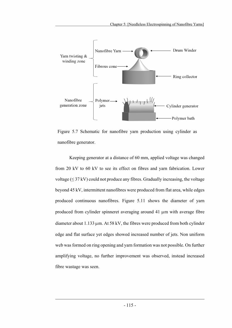
Chapter 5: [Needleless Electrospinning of Nanofibre Yarns]
- 115 -
Keeping generator at a distance of 60 mm, applied voltage was changed
from 20 kV to 60 kV to see its effect on fibres and yarn fabrication. Lower
voltage (≤ 37 kV) could not produce any fibres. Gradually increasing, the voltage
beyond 45 kV, intermittent nanofibres were produced from flat area, while edges
produced continuous nanofibres. Figure 5.11 shows the diameter of yarn
produced from cylinder spinneret averaging around 41 m with average fibre
diameter about 1.133 m. At 58 kV, the fibres were produced from both cylinder
edge and flat surface yet edges showed increased number of jets. Non uniform
web was formed on ring opening and yarn formation was not possible. On further
amplifying voltage, no further improvement was observed, instead increased
fibre wastage was seen.
Figure 5.7 Schematic for nanofibre yarn production using cylinder as
nanofibre generator.
Chapter 5: [Needleless Electrospinning of Nanofibre Yarns]
- 116 -
5.3.2 Circular Coil Generator
The circular coil generator was also used to generate nanofibres and
convert them in to nanofibre yarn. The fibres were produced from top edges of
all coil turns. The jets produced from outer coil were comparatively finer and
had longer life than inner coil turns. The fibres from outer coils were partially
flying away from target. Although fibres from inner coils were focused towards
ring collector, yet inner coil jets were instable and frequently distracted by outer
jets. Despite that the web formed on ring opening was better than cylinder
generator; it still contained fused fibres, which resisted dragging to other side
similar to cylinder generator. The fibrous cone was hard to form, resulting in
short pieces of yarns as shown in Table 5.1b.
The effect of distance, in the case of coil generator was similar to
cylinder. The wet fibres were electrospun when spinning distance was shorter
than 42 mm. Fibres morphology slowly improved with increasing distance to 55
mm, yet fibre loss occurred on higher distances (65 mm ≥). At lower applied
voltages (≥ 34 kV) the coil, behaved like a cylinder generator, i.e., outer coils
produced more jets and fibres, whereas, inner coils produced intermittent
nanofibres. Increasing applied voltage to 55 kV, all the coil tops started
generating fibres, still outer coils were more productive. Although increasing
voltage (60 kV ≥) augmented fibre production, the fibres produced on such high
voltage from outer coils went astray and could not reach ring collector. Whereas,
central coils suffered interference from outer coils and jets initiation was largely
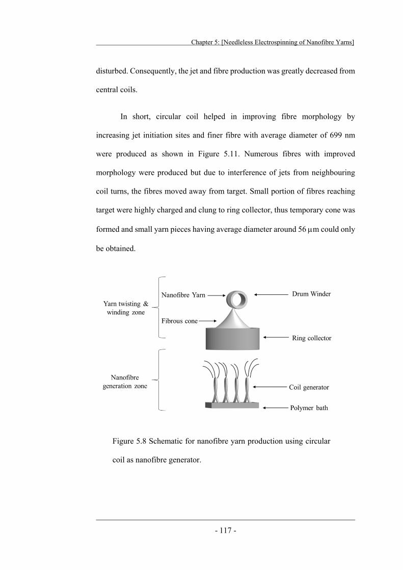
Chapter 5: [Needleless Electrospinning of Nanofibre Yarns]
- 117 -
disturbed. Consequently, the jet and fibre production was greatly decreased from
central coils.
In short, circular coil helped in improving fibre morphology by
increasing jet initiation sites and finer fibre with average diameter of 699 nm
were produced as shown in Figure 5.11. Numerous fibres with improved
morphology were produced but due to interference of jets from neighbouring
coil turns, the fibres moved away from target. Small portion of fibres reaching
target were highly charged and clung to ring collector, thus temporary cone was
formed and small yarn pieces having average diameter around 56 m could only
be obtained.
Figure 5.8 Schematic for nanofibre yarn production using circular
coil as nanofibre generator.
Chapter 5: [Needleless Electrospinning of Nanofibre Yarns]
- 118 -
5.3.3 Ring Generator
When ring generator was utilized to produce nanofibre to formulate
fibrous cone and nanofibre yarn (Figure 5.9), initially fairly distributed jets were
produced on ring surface. These jets were consistent and stayed longer on ring
surface in comparison to cylinder and coil generators. Secondary jets were
observed emerging from inner ring surface. The secondary jet initiation from
inner ring surface distracted jets on upper ring surface. Ultimately, disturbing jet
position and reducing jet stability. As majority of the fibres were dry and mainly
deposited on a narrow area on the ring, they formed a denser web and covered
most of ring area. To form a fibrous cone this web was manually pulled to other
side of ring collector. This web was highly charged and stuck to ring collector.
The fibrous cone was formed temporarily and cracked immediately after. A short
strand of twisted nanofibres formed as shown in Table 5.1 c.
The smaller ring to generator distances (≤ 40 mm) proved to be
inefficient and frequent wet fibrous area formed. When spinneret was beyond a
distance of 55 mm, nanofibres produced were dry with occasional wet and fused
fibres. The distances farther than 62 mm, did not help in further drying of
nanofibres, rather fibres movement away from ring collector was observed.
Keeping the spinneret distance at 60 mm, effect of voltage on fibre
morphology and movement was studied. When the applied voltage was lower
than 31 kV, hardly any jet could be seen ejecting from ring surface. Increasing
applied voltage to 40 kV, numerous jets started appearing on the ring top surface,
with few random jets issuing from inner ring surface. Increasing voltage to 49
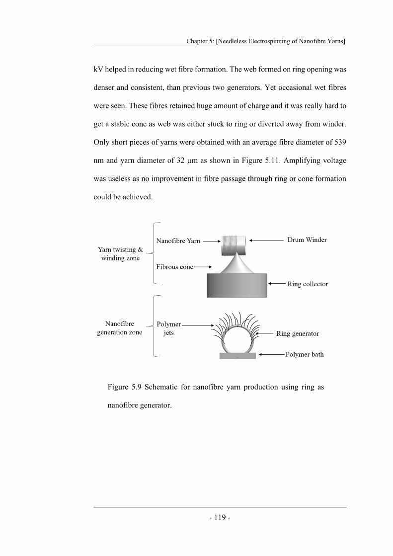
Chapter 5: [Needleless Electrospinning of Nanofibre Yarns]
- 119 -
kV helped in reducing wet fibre formation. The web formed on ring opening was
denser and consistent, than previous two generators. Yet occasional wet fibres
were seen. These fibres retained huge amount of charge and it was really hard to
get a stable cone as web was either stuck to ring or diverted away from winder.
Only short pieces of yarns were obtained with an average fibre diameter of 539
nm and yarn diameter of 32 μm as shown in Figure 5.11. Amplifying voltage
was useless as no improvement in fibre passage through ring or cone formation
could be achieved.
Figure 5.9 Schematic for nanofibre yarn production using ring as
nanofibre generator.
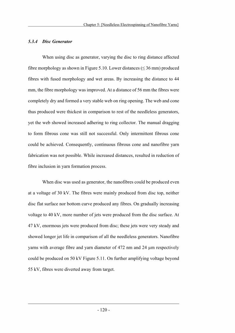
Chapter 5: [Needleless Electrospinning of Nanofibre Yarns]
- 120 -
5.3.4 Disc Generator
When using disc as generator, varying the disc to ring distance affected
fibre morphology as shown in Figure 5.10. Lower distances (≤ 36 mm) produced
fibres with fused morphology and wet areas. By increasing the distance to 44
mm, the fibre morphology was improved. At a distance of 56 mm the fibres were
completely dry and formed a very stable web on ring opening. The web and cone
thus produced were thickest in comparison to rest of the needleless generators,
yet the web showed increased adhering to ring collector. The manual dragging
to form fibrous cone was still not successful. Only intermittent fibrous cone
could be achieved. Consequently, continuous fibrous cone and nanofibre yarn
fabrication was not possible. While increased distances, resulted in reduction of
fibre inclusion in yarn formation process.
When disc was used as generator, the nanofibres could be produced even
at a voltage of 30 kV. The fibres were mainly produced from disc top, neither
disc flat surface nor bottom curve produced any fibres. On gradually increasing
voltage to 40 kV, more number of jets were produced from the disc surface. At
47 kV, enormous jets were produced from disc; these jets were very steady and
showed longer jet life in comparison of all the needleless generators. Nanofibre
yarns with average fibre and yarn diameter of 472 nm and 24 μm respectively
could be produced on 50 kV Figure 5.11. On further amplifying voltage beyond
55 kV, fibres were diverted away from target.
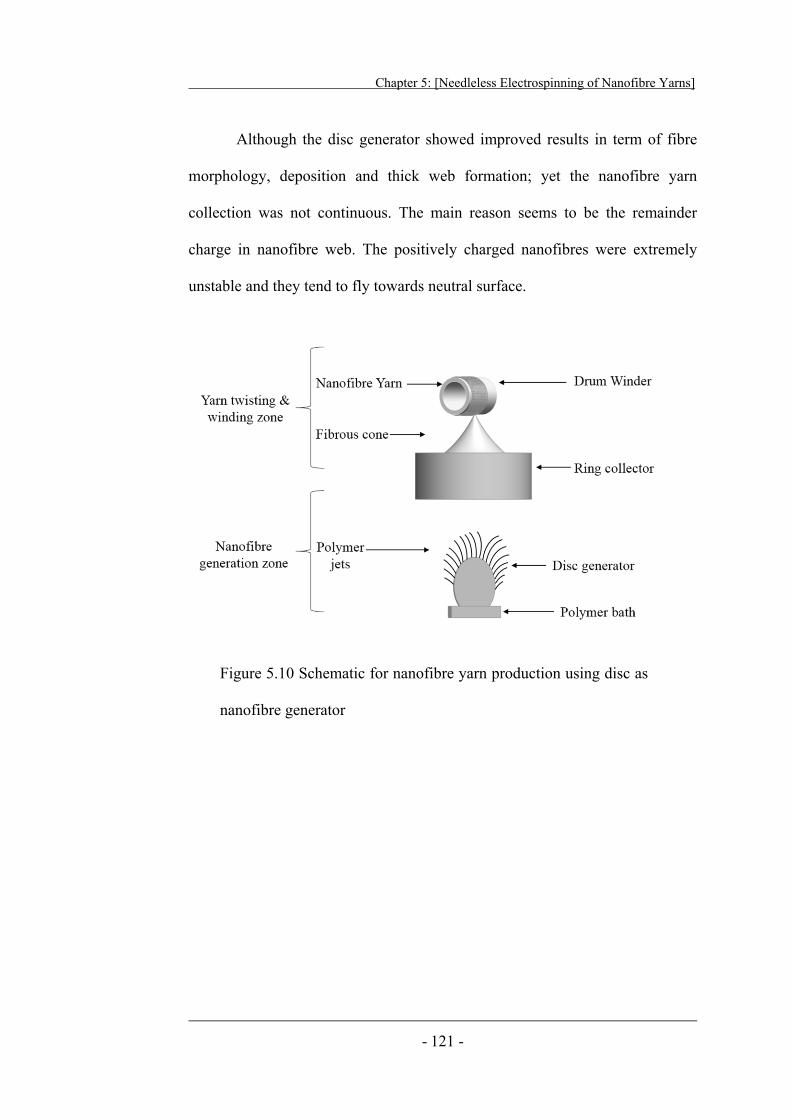
Chapter 5: [Needleless Electrospinning of Nanofibre Yarns]
- 121 -
Although the disc generator showed improved results in term of fibre
morphology, deposition and thick web formation; yet the nanofibre yarn
collection was not continuous. The main reason seems to be the remainder
charge in nanofibre web. The positively charged nanofibres were extremely
unstable and they tend to fly towards neutral surface.
Figure 5.10 Schematic for nanofibre yarn production using disc as
nanofibre generator
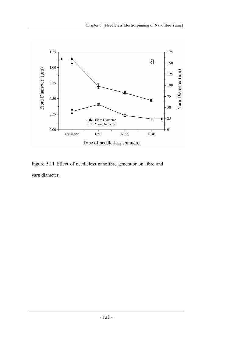
Chapter 5: [Needleless Electrospinning of Nanofibre Yarns]
- 122 -
Figure 5.11 Effect of needleless nanofibre generator on fibre and
yarn diameter.
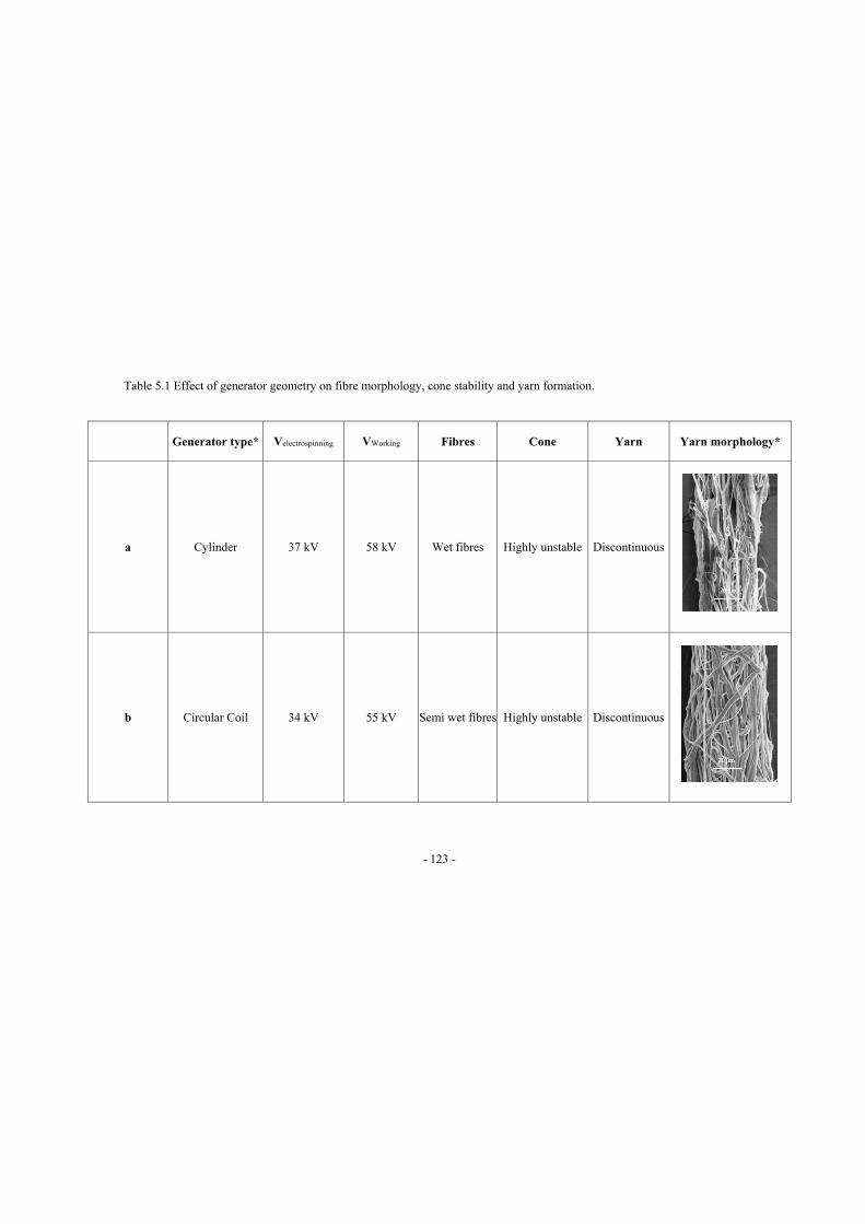
- 123 -
Table 5.1 Effect of generator geometry on fibre morphology, cone stability and yarn formation.
Generator type* Velectrospinning VWorking Fibres Cone Yarn Yarn morphology*
a Cylinder 37 kV 58 kV Wet fibres Highly unstable Discontinuous
b Circular Coil 34 kV 55 kV Semi wet fibres Highly unstable Discontinuous
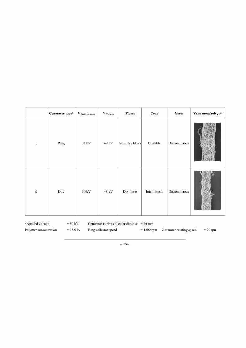
- 124 -
Generator type* Velectrospinning VWorking Fibres Cone Yarn Yarn morphology*
c Ring 31 kV 49 kV Semi dry fibres Unstable Discontinuous
d Disc 30 kV 48 kV Dry fibres Intermittent Discontinuous
*Applied voltage = 50 kV Generator to ring collector distance = 60 mm
Polymer concentration = 15.0 % Ring collector speed = 1200 rpm Generator rotating speed = 20 rpm
Chapter 5: [Needleless Electrospinning of Nanofibre Yarns]
- 125 -
5.3.5 Modified Yarn Electrospinning System
Auxiliary Metallic Electrode
Disc generator showed greater possibility to produce nanofibre yarn than
other needleless fibre generators, yet number of fibres forming fibrous cone were
not enough to produce a stable cone. Consequently nanofibre yarn fabrication
was not continuous. To provide sufficient fibres for yarn production, an auxiliary
metallic electrode was placed just above the polymer bath. The metal electrode
had the same electric potential as that of polymer bath (Figure 5.12).
It was noticed that by using auxiliary electrode, more and thicker jets
were produced on disc top. These jets could not properly stretch and dry, the
cone and as-prepared yarn had larger diameter but with fused fibre morphology
as shown in Figure 5.14. Continuous and proper yarn formation using auxiliary
electrode was not possible.
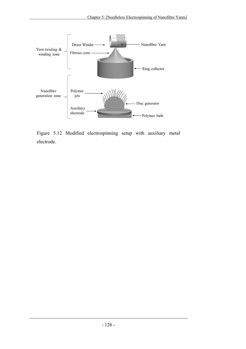
Chapter 5: [Needleless Electrospinning of Nanofibre Yarns]
- 126 -
Figure 5.12 Modified electrospinning setup with auxiliary metal
electrode.
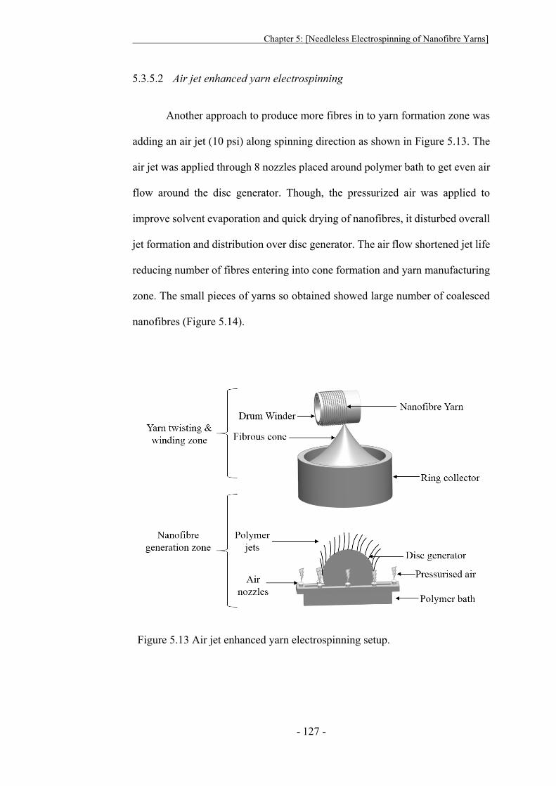
Chapter 5: [Needleless Electrospinning of Nanofibre Yarns]
- 127 -
Air jet enhanced yarn electrospinning
Another approach to produce more fibres in to yarn formation zone was
adding an air jet (10 psi) along spinning direction as shown in Figure 5.13. The
air jet was applied through 8 nozzles placed around polymer bath to get even air
flow around the disc generator. Though, the pressurized air was applied to
improve solvent evaporation and quick drying of nanofibres, it disturbed overall
jet formation and distribution over disc generator. The air flow shortened jet life
reducing number of fibres entering into cone formation and yarn manufacturing
zone. The small pieces of yarns so obtained showed large number of coalesced
nanofibres (Figure 5.14).
Figure 5.13 Air jet enhanced yarn electrospinning setup.
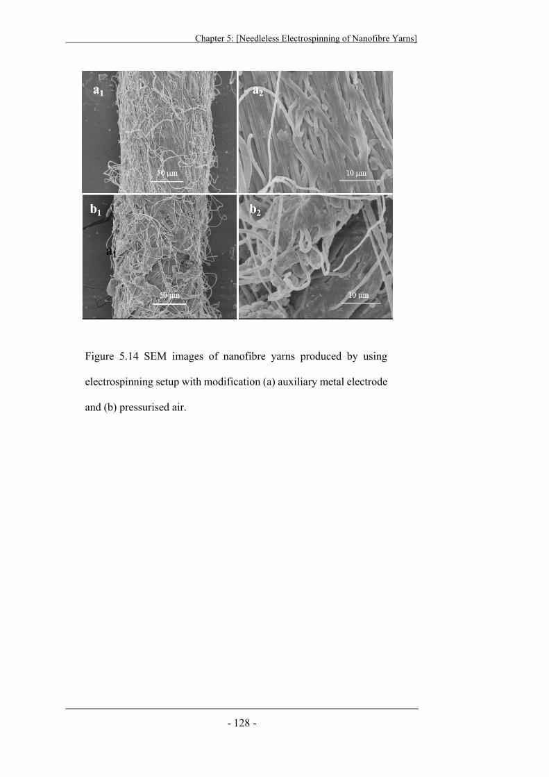
Chapter 5: [Needleless Electrospinning of Nanofibre Yarns]
- 128 -
Figure 5.14 SEM images of nanofibre yarns produced by using
electrospinning setup with modification (a) auxiliary metal electrode
and (b) pressurised air.
Chapter 5: [Needleless Electrospinning of Nanofibre Yarns]
- 129 -
5.4 Conclusion
In this chapter, use of needleless generators to produce nanofibre yarn
has been described. Four needleless generators (cylinder, coil, ring and disc)
were accessed to fabricate nanofibre yarn from the new developed
electrospinning setup. The needle generators were replaced with different
needleless generators.
The nanofibres produced from cylinder generators showed huge amount
of solvent entrapped inside the fibre. The majority of fibres were fused together
to form film on ring surface. The reasons for this include overall lower electric
field of cylinder generator, variations of electric field from edge to flat
cylindrical part, enormous amount of solution over cylinder surface. All these
factors produced wet fibres and distorted web on ring collector opening. The jet
sizes and positions varied from central cylinder to cylinder edge. The edges
produced frequent jets with long jet life, while, jets from central part were
scattered and discontinuous. The nanofibre yarn produced from cylinder
generator, was composed of almost all fused nanofibres. Due to wet and fused
fibres, it was very difficult to get web accumulation over ring opening;
consequently, no cone or yarn could be fabricated from cylinder generator.
The fibres produced from coil generator showed improved morphology
from cylinder yet it still contained fused fibres. The fibres were produced from
each coil individually, but at the same time, the jets from inner coils were
distracted by outer coils. Thus the jet interference caused fusing of jets from
different coils. The yarn produced from coil generator showed fused morphology
Chapter 5: [Needleless Electrospinning of Nanofibre Yarns]
- 130 -
of fibres. The web formed at the ring opening was distorted and had wet patches.
The cone could not be formed under these conditions and only very small piece
of yarn could be obtained.
The ring and disc generators both showed comparatively improved
nanofibre morphology in final nanofibre yarn. Although the outer jets were
slightly distracted by inner ring jets but overall web showed dry nanofibres. The
webs formed by both ring and disc generators on ring opening were thicker than
coil and cylinder generators. On dragging the web to fabricate yarn, the web
showed resistance. The highly charged web either stuck to ring collector or
drifted away from drum winder. The cone was momentarily formed and ruptured
from bottom near ring collector or top near drum winder. The disc generator
setup was modified to enhance nanofibre production by using auxiliary metal
electrode or enhanced air jets. The both modifications did not work. Instead, the
jet stability was affected and wet fused nanofibres were collected.
In conclusion, it was difficult to produce continuous nanofibre yarns
from needleless generators. Stable cone could not be achieved in any of the four
needleless generator systems. The cone stability was mainly disturbed either by
wet fibres or by large remaining charges in the final web. Therefore, needleless
generators alone could not be used to produce properly dried continuous
nanofibre yarn.
- 131 -
C H A P T E R S I X
6 Nanofibre Yarn Prepared by Hybrid
Electrospinning Systems
In this chapter, novel technique of using a ring collector and a hybrid
electrospinning system consisting of both needle and needleless fibre spinneret
was developed to prepare nanofibre yarns. By combining a disc-based fibre
generator with a needle generator, the system could produce nanofibre yarns at
considerably increased production rates. Effects of electrospinning setup, disc
parameters from the disc generator and processing factors on nanofibre
fibre/yarn morphology, diameter, yarn formation, twists levels and mechanical
properties were examined. A finite element method was also employed to
analyse the effect of different disc generator materials on electrospinning
capabilities.
6.1 Experimental
6.1.1 Preparation of Nanofibres
A purpose-built electrospinning setup was used to prepare nanofibre
yarns. The modified system comprised of one needle-based electrospinning, a
disc based needleless electrospinning, an intermediate ring collector, and a drum
winder, as schematically shown in Figure 6.1. The disc and the needle generators
were separately connected to the positive high-voltage power supply (RR100-
2P/240, Gamma High Voltage Research 0~100 kV) and negative high-voltage
power supply (ES30P, Gamma High Voltage Research 0~50 kV), respectively.
Chapter 6: [Nanofibre Yarn Prepared by Hybrid Electrospinning System]
- 132 -
The ring collector was 40 mm wide, with outer and inner diameter of 100 mm
and 88 mm, respectively. The ring collector was placed horizontally on a HDP
(high density polyethylene) base mounted with a ball bearing to lower friction
in rotation. A variable speed motor was connected to ring collector through an
O-ring belt to control rotation speed of ring collector.
The disc spinneret produced nanofibres upwards, while the needle
generator which was placed near the ring collector produced nanofibres from
top. The nanofibres were initially deposited on the ring collector surface. A
fibrous web was formed on ring aperture when ring rotated. An inverted fibrous
cone was formed by manually dragging this web using a plastic rod. The edge
of cone was drawn endlessly into nanofibre yarn.
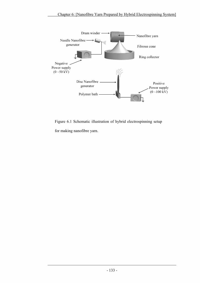
Chapter 6: [Nanofibre Yarn Prepared by Hybrid Electrospinning System]
- 133 -
Figure 6.1 Schematic illustration of hybrid electrospinning setup
for making nanofibre yarn.
Chapter 6: [Nanofibre Yarn Prepared by Hybrid Electrospinning System]
- 134 -
6.2 Yarn Formation in the Hybrid System
Figure 6.1 schematically illustrates the modified setup for
electrospinning of hybrid nanofibre yarns. The polymer solution was fed through
a syringe to the needle nozzle, while a solution was loaded on disc generator
from a solution bath underneath it. The needle generator was connected to a
negative high power supply whereas, polymer solution bath was electrically
charged by a positive high power supply. Two electrospinning systems produced
oppositely charged nanofibres.
Initially, when ring collector was not moving, most of the fibres got
deposited on ring surface, but no web was formed on ring opening. A fibrous
web was formed on ring opening when it rotated. An inverted fibrous cone was
then formed through drawing the fibrous web from the central part (Figure 6.2a).
The cone apex was continually drawn by the winder, while the ring collector
rotated at a high speed. In this way, a twisted nanofibre yarn was produced from
the system as shown in Figure 6.2b & c.
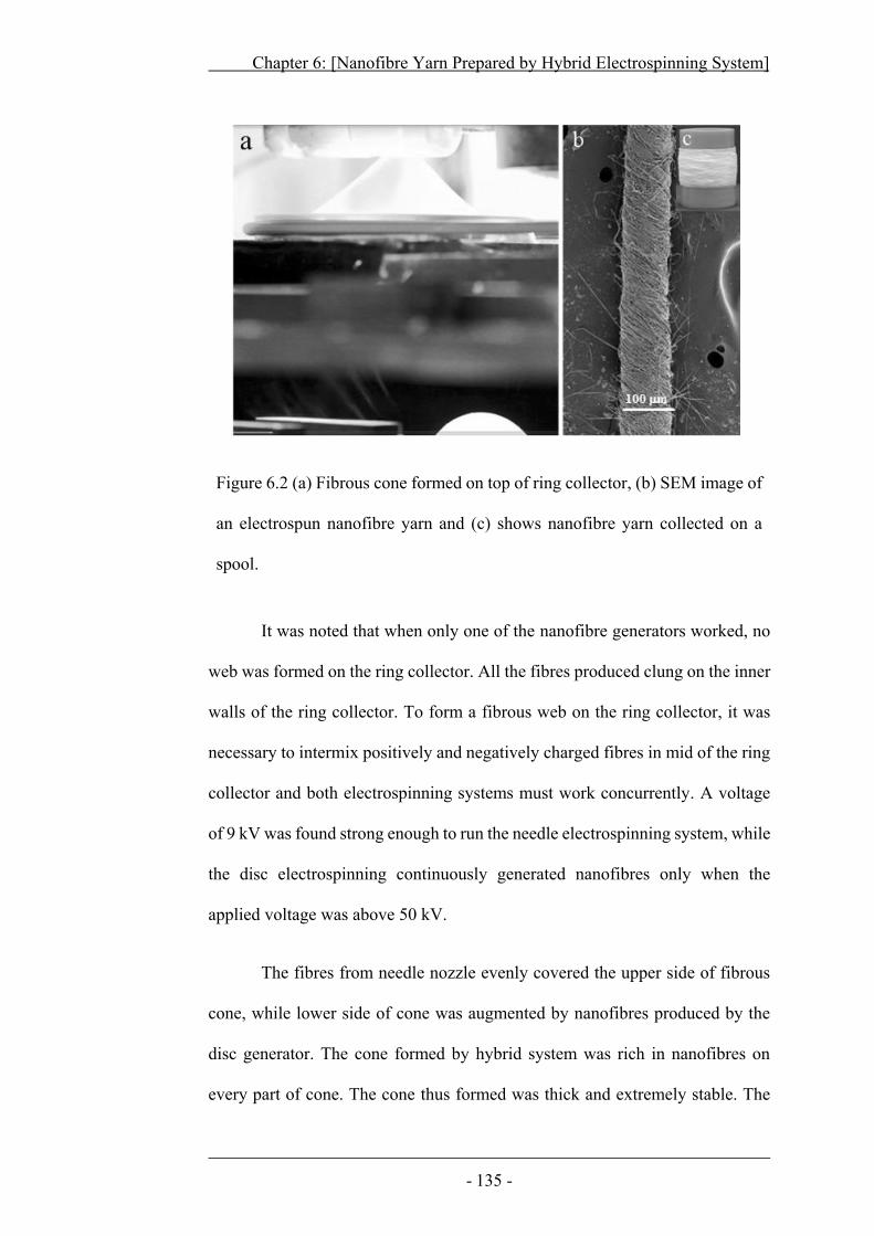
Chapter 6: [Nanofibre Yarn Prepared by Hybrid Electrospinning System]
- 135 -
Figure 6.2 (a) Fibrous cone formed on top of ring collector, (b) SEM image of
an electrospun nanofibre yarn and (c) shows nanofibre yarn collected on a
spool.
It was noted that when only one of the nanofibre generators worked, no
web was formed on the ring collector. All the fibres produced clung on the inner
walls of the ring collector. To form a fibrous web on the ring collector, it was
necessary to intermix positively and negatively charged fibres in mid of the ring
collector and both electrospinning systems must work concurrently. A voltage
of 9 kV was found strong enough to run the needle electrospinning system, while
the disc electrospinning continuously generated nanofibres only when the
applied voltage was above 50 kV.
The fibres from needle nozzle evenly covered the upper side of fibrous
cone, while lower side of cone was augmented by nanofibres produced by the
disc generator. The cone formed by hybrid system was rich in nanofibres on
every part of cone. The cone thus formed was thick and extremely stable. The
Chapter 6: [Nanofibre Yarn Prepared by Hybrid Electrospinning System]
- 136 -
cone apex could be drawn and drafted on higher winding speeds resulting in
increased production rates. The hybrid system was also capable of processing a
high volume (approximately 6.5 ml/h) of polymer solution, which was higher
than that of the previously designed needles generator (3.0 ml/h) and needleless
generator systems (4.5 ml/h).
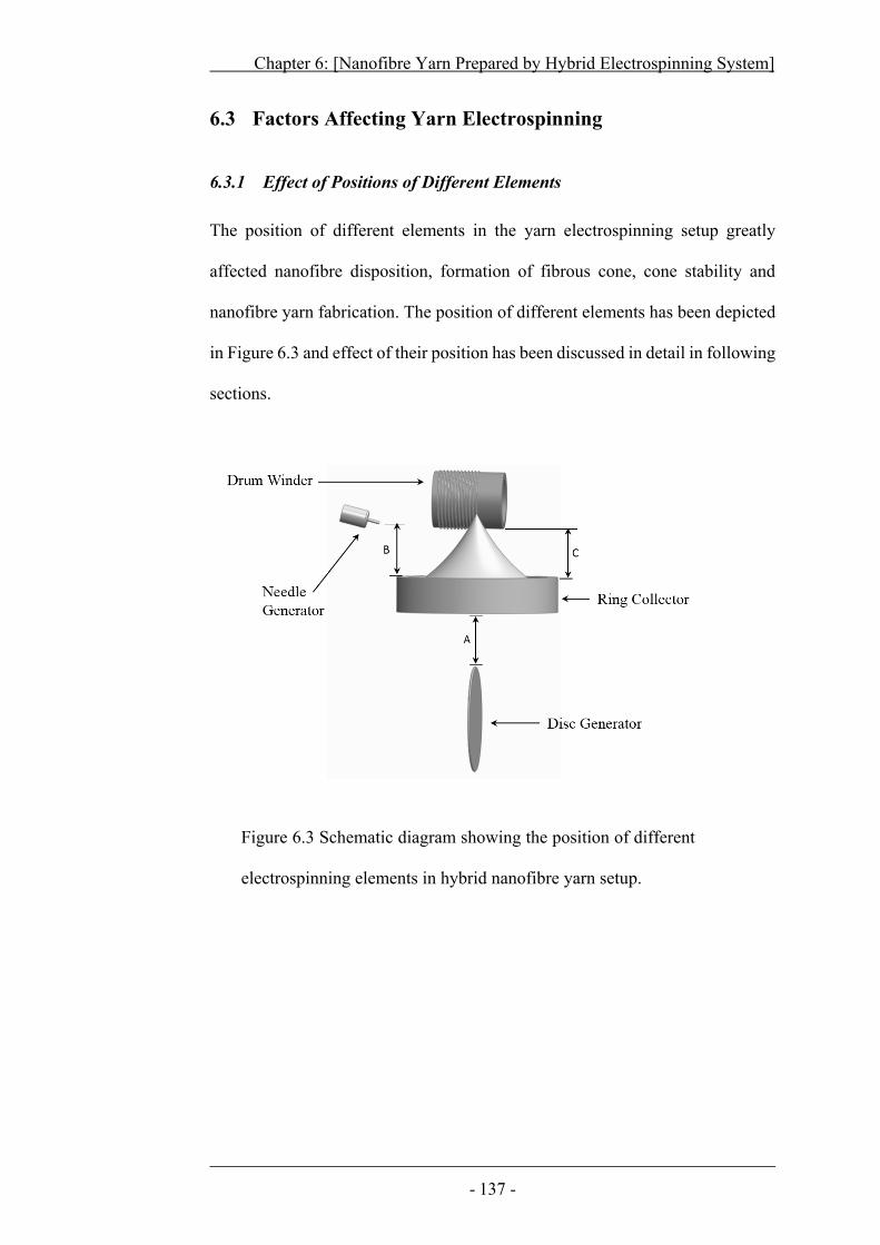
Chapter 6: [Nanofibre Yarn Prepared by Hybrid Electrospinning System]
- 137 -
6.3 Factors Affecting Yarn Electrospinning
6.3.1 Effect of Positions of Different Elements
The position of different elements in the yarn electrospinning setup greatly
affected nanofibre disposition, formation of fibrous cone, cone stability and
nanofibre yarn fabrication. The position of different elements has been depicted
in Figure 6.3 and effect of their position has been discussed in detail in following
sections.
Figure 6.3 Schematic diagram showing the position of different
electrospinning elements in hybrid nanofibre yarn setup.
Chapter 6: [Nanofibre Yarn Prepared by Hybrid Electrospinning System]
- 138 -
6.3.1.1 Disc generator position
The position of fibre generators was crucial for this yarn electrospinning
process. Table 6.1 summarizes the effect of nanofibre generators on the stability
of fibrous cone and yarn formation. It was important to position the disc
generator beneath the centre of the ring collector. In this way, the nanofibres
were deposited evenly on the ring collector. Asymmetrical distribution of
nanofibres resulted when the disc generator was move away from the central line
of the ring collector, which led to uneven deposition of nanofibres on ring open
and destabilized cone.
The distance between the disc and the ring collector played a key role in
determining the yarn formation. When the distance was less than 30 mm, wet
fibres formed, which struck inside the ring. As a result, no fibrous cone and
nanofibre yarn were prepared. Thin fibrous cone and discontinuous yarn could
be obtained when the disc-ring distance was between 32 mm to 49 mm. In this
case, most of the fibres were found to be fused together.
When the distance was in the range of 50 ~ 60 mm, a continuous cone
and incessant yarn was formed. Further increasing the distance to 62 ~ 68 mm
resulted in thinner cone with frequent yarn breakage. At such a high distance,
lots of nanofibres flew into the air, leaving only a small amount of nanofibres to
add onto the fibrous cone. However, no cone or yarn was produced when the
disc-ring distance was larger than 72 mm.
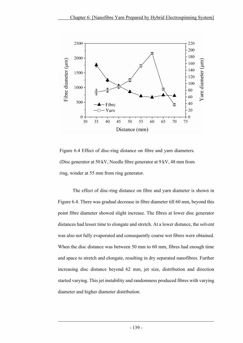
Chapter 6: [Nanofibre Yarn Prepared by Hybrid Electrospinning System]
- 139 -
Figure 6.4 Effect of disc-ring distance on fibre and yarn diameters.
(Disc generator at 50 kV, Needle fibre generator at 9 kV, 48 mm from
ring, winder at 55 mm from ring generator.
The effect of disc-ring distance on fibre and yarn diameter is shown in
Figure 6.4. There was gradual decrease in fibre diameter till 60 mm, beyond this
point fibre diameter showed slight increase. The fibres at lower disc generator
distances had lesser time to elongate and stretch. At a lower distance, the solvent
was also not fully evaporated and consequently coarse wet fibres were obtained.
When the disc distance was between 50 mm to 60 mm, fibres had enough time
and space to stretch and elongate, resulting in dry separated nanofibres. Further
increasing disc distance beyond 62 mm, jet size, distribution and direction
started varying. This jet instability and randomness produced fibres with varying
diameter and higher diameter distribution.
Chapter 6: [Nanofibre Yarn Prepared by Hybrid Electrospinning System]
- 140 -
With increasing the distance, the yarn diameter increased initially until
the distance reached 60 mm. The yarn diameter then decreased rapidly with
further increasing the distance. At lower distances, wet fibres resulted which
fused together, leading to yarns with smaller diameter. Gradually increasing the
disc-generator distance from 50 mm and above facilitated to produce dry, well
separated nanofibres. Yarns produced on these distances showed larger
diameters. On further increasing disc distance beyond 62 mm, fibres flew off the
target. Consequently the cone lacked nanofibres and the number of fibres in final
yarn dramatically reduced. The yarn produced on such high disc distances
showed a declined trend in diameter.
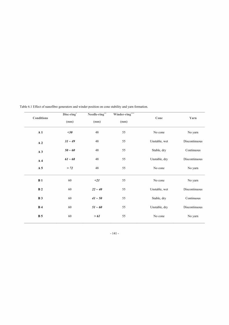
- 141 -
Conditions Disc-ring*
(mm)
Needle-ring**
(mm)
Winder-ring***
(mm) Cone Yarn
A 1 <30 48 55 No cone No yarn
A 2 31 ~ 49 48 55 Unstable, wet Discontinuous
A 3 50 ~ 60 48 55 Stable, dry Continuous
A 4 61 ~ 68 48 55 Unstable, dry Discontinuous
A 5 > 72 48 55 No cone No yarn
B 1 60 <21 55 No cone No yarn
B 2 60 22 ~ 40 55 Unstable, wet Discontinuous
B 3 60 41 ~ 50 55 Stable, dry Continuous
B 4 60 51 ~ 60 55 Unstable, dry Discontinuous
B 5 60 > 61 55 No cone No yarn
Table 6.1 Effect of nanofibre generators and winder position on cone stability and yarn formation.
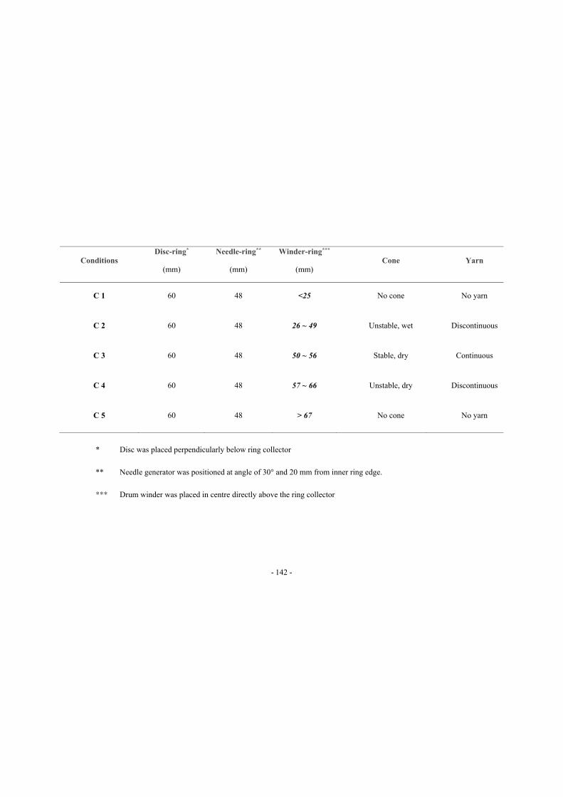
- 142 -
Conditions Disc-ring*
(mm)
Needle-ring**
(mm)
Winder-ring***
(mm) Cone Yarn
C 1 60 48 <25 No cone No yarn
C 2 60 48 26 ~ 49 Unstable, wet Discontinuous
C 3 60 48 50 ~ 56 Stable, dry Continuous
C 4 60 48 57 ~ 66 Unstable, dry Discontinuous
C 5 60 48 > 67 No cone No yarn
* Disc was placed perpendicularly below ring collector
** Needle generator was positioned at angle of 30° and 20 mm from inner ring edge.
*** Drum winder was placed in centre directly above the ring collector
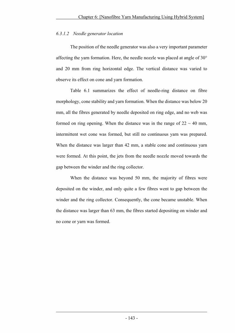
Chapter 6: [Nanofibre Yarn Manufacturing Using Hybrid System]
- 143 -
6.3.1.2 Needle generator location
The position of the needle generator was also a very important parameter
affecting the yarn formation. Here, the needle nozzle was placed at angle of 30°
and 20 mm from ring horizontal edge. The vertical distance was varied to
observe its effect on cone and yarn formation.
Table 6.1 summarizes the effect of needle-ring distance on fibre
morphology, cone stability and yarn formation. When the distance was below 20
mm, all the fibres generated by needle deposited on ring edge, and no web was
formed on ring opening. When the distance was in the range of 22 ~ 40 mm,
intermittent wet cone was formed, but still no continuous yarn was prepared.
When the distance was larger than 42 mm, a stable cone and continuous yarn
were formed. At this point, the jets from the needle nozzle moved towards the
gap between the winder and the ring collector.
When the distance was beyond 50 mm, the majority of fibres were
deposited on the winder, and only quite a few fibres went to gap between the
winder and the ring collector. Consequently, the cone became unstable. When
the distance was larger than 63 mm, the fibres started depositing on winder and
no cone or yarn was formed.
Chapter 6: [Nanofibre Yarn Prepared by Hybrid Electrospinning Systems]
- 144 -
6.3.1.3 Winder location
The ring-winder distance also affected cone and yarn formation. When
winder was placed less than 25 mm away from the ring collector, the wet
nanofibres generated from the needle nozzle were deposited on the winder, and
in this case, neither fibrous cone nor yarn was produced. When the distance was
in the range between 27 mm and 48 mm, fibres deposited partly on ring and
partly on winder, still no cone or yarn was formed.
At a distance of 50 mm, fibres from needle generator accumulated on gap
between the winder and the ring collector. At this stage, a very stable cone was
formed and a continuous yarn could be drawn. When the winder-ring distance
was larger than 58 mm, the cone frequently ruptured and discontinuous yarn was
produced. Larger distance beyond 68 mm disturbed the balance between
nanofibre generation, cone formation and yarn drawing. As result, the cone was
not formed and no yarn could be produced.
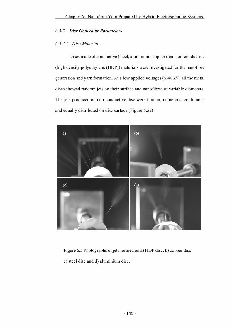
Chapter 6: [Nanofibre Yarn Prepared by Hybrid Electrospinning Systems]
- 145 -
6.3.2 Disc Generator Parameters
6.3.2.1 Disc Material
Discs made of conductive (steel, aluminium, copper) and non-conductive
(high density polyethylene (HDP)) materials were investigated for the nanofibre
generation and yarn formation. At a low applied voltages (≤ 40 kV) all the metal
discs showed random jets on their surface and nanofibres of variable diameters.
The jets produced on non-conductive disc were thinner, numerous, continuous
and equally distributed on disc surface (Figure 6.5a)
Figure 6.5 Photographs of jets formed on a) HDP disc, b) copper disc
c) steel disc and d) aluminium disc.
Chapter 6: [Nanofibre Yarn Prepared by Hybrid Electrospinning Systems]
- 146 -
Conversely, the jet formation on the metal discs was thicker, fewer,
discontinuous, and irregular mainly on disc top (Figure 6.5 b ~ d). When the
applied voltage was above 50 kV, a corona discharge took place on all the metal
discs. In contrast, the HDP disc could produce nanofibres without corona
discharge even up to 65 kV of applied voltage.
Figure 6.6 Simulated electric field profile of polymer layer on a) conductive
disc and b) non-conductive disc
Electric field analysis for different disc materials was performed using a
finite element method as shown in Figure 6.6. At the same applied voltage, the
electric field intensity around the disc top in case of conductive disc was greater
than that on the non-conductive disc. The electric field intensity at bottom in the
conductive disc was same as that at top. However, in the case of non-conductive
disc, the electric field at disc bottom was higher than that of disc top. This shows
that the conductive disc behaved as equipotential surface from one edge to other
edge.
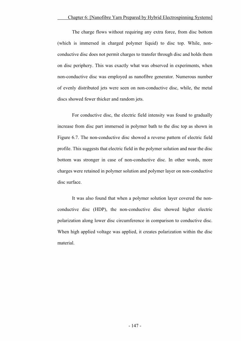
Chapter 6: [Nanofibre Yarn Prepared by Hybrid Electrospinning Systems]
- 147 -
The charge flows without requiring any extra force, from disc bottom
(which is immersed in charged polymer liquid) to disc top. While, non-
conductive disc does not permit charges to transfer through disc and holds them
on disc periphery. This was exactly what was observed in experiments, when
non-conductive disc was employed as nanofibre generator. Numerous number
of evenly distributed jets were seen on non-conductive disc, while, the metal
discs showed fewer thicker and random jets.
For conductive disc, the electric field intensity was found to gradually
increase from disc part immersed in polymer bath to the disc top as shown in
Figure 6.7. The non-conductive disc showed a reverse pattern of electric field
profile. This suggests that electric field in the polymer solution and near the disc
bottom was stronger in case of non-conductive disc. In other words, more
charges were retained in polymer solution and polymer layer on non-conductive
disc surface.
It was also found that when a polymer solution layer covered the non-
conductive disc (HDP), the non-conductive disc showed higher electric
polarization along lower disc circumference in comparison to conductive disc.
When high applied voltage was applied, it creates polarization within the disc
material.
Chapter 6: [Nanofibre Yarn Prepared by Hybrid Electrospinning Systems]
- 148 -
Figure 6.7 Calculated electric field profile of polymer layer on a) conductive
disc and b) non-conductive disc.
Chapter 6: [Nanofibre Yarn Prepared by Hybrid Electrospinning Systems]
- 149 -
6.3.2.2 Disc Diameter
The diameter of disc generator was found to affect fibre and yarn
diameters. To examine the effect of disc size on nanofibre and yarn diameter,
HDP (1 mm thick) discs with four different diameters (e.g. 50 mm, 60 mm, 70
mm and 80 mm) were employed. When disc size was small (e.g. 50 mm), fewer
jets were generated, leading to wet coarse fibres. These wet fibres were sticky
and hard to form a continuous cone, therefore, no continuous yarn was produced.
As the disc diameter was increased, number of jets on disc surface increased and
dry fibres were produced, which led to the formation of a stable cone and
continuous yarn production.
Figure 6.8 shows the effect of disc size on fibre and yarn diameters. By
increasing disc generator diameter, a declining trend was observed in nanofibre
diameter with maximum attenuation on 80 mm diameter disc. These results
comply with the work of other researchers who reported similar trends while
using discs of different diameters sizes 264,265. It was described in their work that
larger diameter discs showed higher electric field intensity in comparison to
small size discs. This high electric field intensity in non-conductive disc led to
more charges being accumulated on disc surface, increasing number of equally
spaced jets. The fibres were thus produced in higher productivity with lower
diameter. The yarn consisting of these finer well separated finer fibres showed
larger yarn diameters. Therefore, increasing the disc diameter led to steady
increase in the yarn diameters. The yarns produced from 80 mm disc had almost
4 times larger diameter than that fabricated from 50 mm disc.
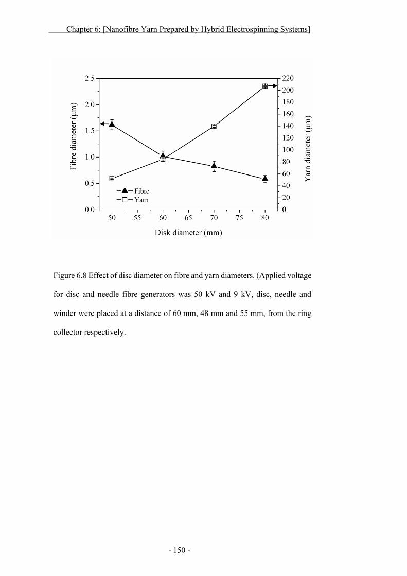
Chapter 6: [Nanofibre Yarn Prepared by Hybrid Electrospinning Systems]
- 150 -
Figure 6.8 Effect of disc diameter on fibre and yarn diameters. (Applied voltage
for disc and needle fibre generators was 50 kV and 9 kV, disc, needle and
winder were placed at a distance of 60 mm, 48 mm and 55 mm, from the ring
collector respectively.
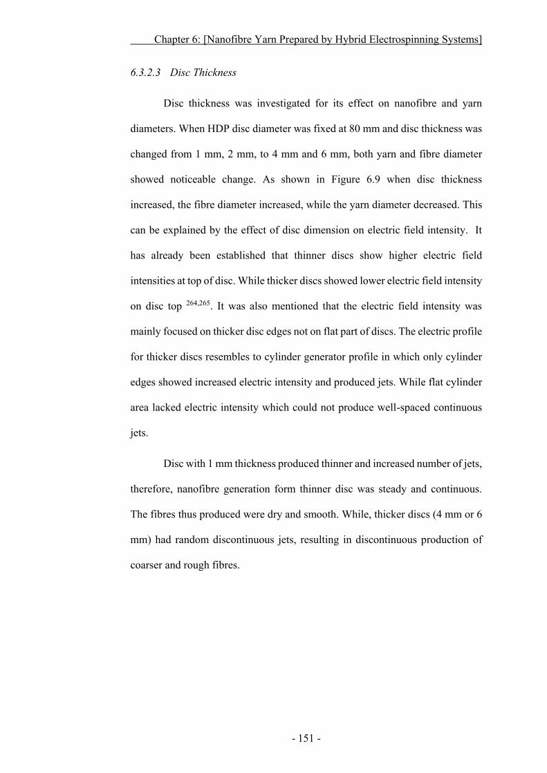
Chapter 6: [Nanofibre Yarn Prepared by Hybrid Electrospinning Systems]
- 151 -
6.3.2.3 Disc Thickness
Disc thickness was investigated for its effect on nanofibre and yarn
diameters. When HDP disc diameter was fixed at 80 mm and disc thickness was
changed from 1 mm, 2 mm, to 4 mm and 6 mm, both yarn and fibre diameter
showed noticeable change. As shown in Figure 6.9 when disc thickness
increased, the fibre diameter increased, while the yarn diameter decreased. This
can be explained by the effect of disc dimension on electric field intensity. It
has already been established that thinner discs show higher electric field
intensities at top of disc. While thicker discs showed lower electric field intensity
on disc top 264,265. It was also mentioned that the electric field intensity was
mainly focused on thicker disc edges not on flat part of discs. The electric profile
for thicker discs resembles to cylinder generator profile in which only cylinder
edges showed increased electric intensity and produced jets. While flat cylinder
area lacked electric intensity which could not produce well-spaced continuous
jets.
Disc with 1 mm thickness produced thinner and increased number of jets,
therefore, nanofibre generation form thinner disc was steady and continuous.
The fibres thus produced were dry and smooth. While, thicker discs (4 mm or 6
mm) had random discontinuous jets, resulting in discontinuous production of
coarser and rough fibres.
Chapter 6: [Nanofibre Yarn Prepared by Hybrid Electrospinning Systems]
- 152 -
Figure 6.9 Effect of disc thickness on fibre and yarn diameters. (Disc
and needle fibre generator at 50 kV and 9 kV respectively; disc,
needle and winder were placed from ring collector at a distance of 60
mm, 48 mm and 55 mm respectively).
The yarn continuity was also largely affected by disc thickness. The
thinner disc resulted in highly stable cone. Although fibres produced by thin disc
were fine, they formulated a yarn with large diameter. This could be due to the
fact that the electric field intensity on thin disc edge was higher when reducing
the disc thickness.
Chapter 6: [Nanofibre Yarn Prepared by Hybrid Electrospinning Systems]
- 153 -
6.3.3 Polymer Concentration
Similar to conventional electrospinning, modified yarn electrospinning
was also affected by polymer concentration. To elucidate the effect of polymer
concentration on fibre and yarn morphologies, PVDF-HFP solutions with
concentration varying from 9.0% to 19.0% were electrospun. Table 6.2
summarizes the effects of polymer concentration on threshold voltage for
electrospinning, fibre morphology, cone stability and continuity in yarn
formation.
When polymer concentration was in the range of 9.0% ~ 11.0%, polymer
viscosity was fairly low and a thin polymer layer thoroughly covered the disc
surface. A large number of jets could be seen at a voltage range of 25 ~ 28 kV.
Although it required 38 ~ 42 kV voltage to run electrospinning smoothly, wet
beaded fibres were generated and it was extremely difficult to produce fibrous
cone and nanofibre yarn.
As the polymer concentration was gradually increased to 13.0%, polymer
viscosity increased, the solution layer on disc was slightly thick. On applying
voltage above 45 kV, semi-continuous jets were produced from disc surface and
dry fibres with smaller beads were observed. At this point, cone stability showed
a little improvement, still yarn fabrication was not continuous. The 15.0%
polymer solution showed increased viscosity and uniform thick polymer
coverage on disc. At a voltage of 50 kV, the jet protrusion was distributed
thoroughly on disc surface. The nanofibres produced from this solution were dry
and bead-free. These dry and well separated fibres led to a steady cone and
incessant yarn production.
Chapter 6: [Nanofibre Yarn Prepared by Hybrid Electrospinning Systems]
- 154 -
At higher polymer concentrations (17.0% and above), polymer viscosity
was such high that the polymer coating on the disc surface became uneven,
leading to random and discontinuous jet initiation. Moreover, higher threshold
voltages (34 to 37 kV) were required to generate nanofibres. For steady
production of nanofibres, still higher voltages (54 to 57 kV) were required. Due
to increased polymer viscosity, the fibres thus produced were coarser and had a
lot of solvent rich areas. These highly charged, wet fibres were hard to go
through ring collector. As there were not enough fibres to support cone, no
continuous yarn was prepared.
Figure 6.10 shows the effect of polymer concentration on fibre and yarn
diameters. At a polymer concentration lower than 11.0%, beaded fibres were
produced. Increasing the polymer concentration to 13.0%, solution viscosity was
enhanced. As a result, reduced fibre beads and fused morphology were noticed.
Yet on such viscosity, coarse semi wet fibres were produced which could not
form a stable cone and yarn.
Bead free fibres could be obtained when the polymer concentration was
above 15.0%. At this point, the viscosity was high enough to produce dry and
well defined fibres, leading to a steady fibrous cone and continuous nanofibre
yarn. However, still when the polymer concentration was higher than 17.0%, the
viscosity was too high to electrospin the solution into fibres.
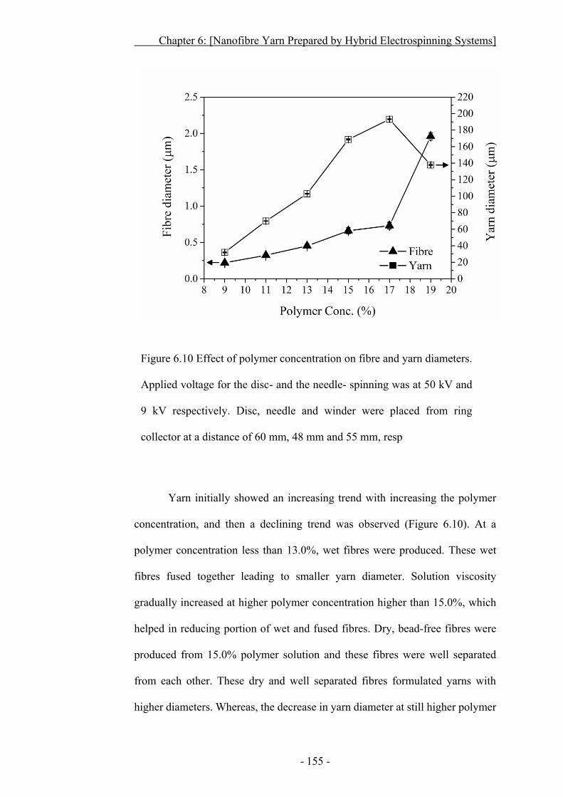
Chapter 6: [Nanofibre Yarn Prepared by Hybrid Electrospinning Systems]
- 155 -
Figure 6.10 Effect of polymer concentration on fibre and yarn diameters.
Applied voltage for the disc- and the needle- spinning was at 50 kV and
9 kV respectively. Disc, needle and winder were placed from ring
collector at a distance of 60 mm, 48 mm and 55 mm, resp
Yarn initially showed an increasing trend with increasing the polymer
concentration, and then a declining trend was observed (Figure 6.10). At a
polymer concentration less than 13.0%, wet fibres were produced. These wet
fibres fused together leading to smaller yarn diameter. Solution viscosity
gradually increased at higher polymer concentration higher than 15.0%, which
helped in reducing portion of wet and fused fibres. Dry, bead-free fibres were
produced from 15.0% polymer solution and these fibres were well separated
from each other. These dry and well separated fibres formulated yarns with
higher diameters. Whereas, the decrease in yarn diameter at still higher polymer
Chapter 6: [Nanofibre Yarn Prepared by Hybrid Electrospinning Systems]
- 156 -
concentrations (19.0%) can be associated to the difficulty in electrospinning. The
high viscosity made it difficult to electrospin nanofibres, as a result few and
coarse fibres were produced. These fibres were not enough to form cone and
yarn.
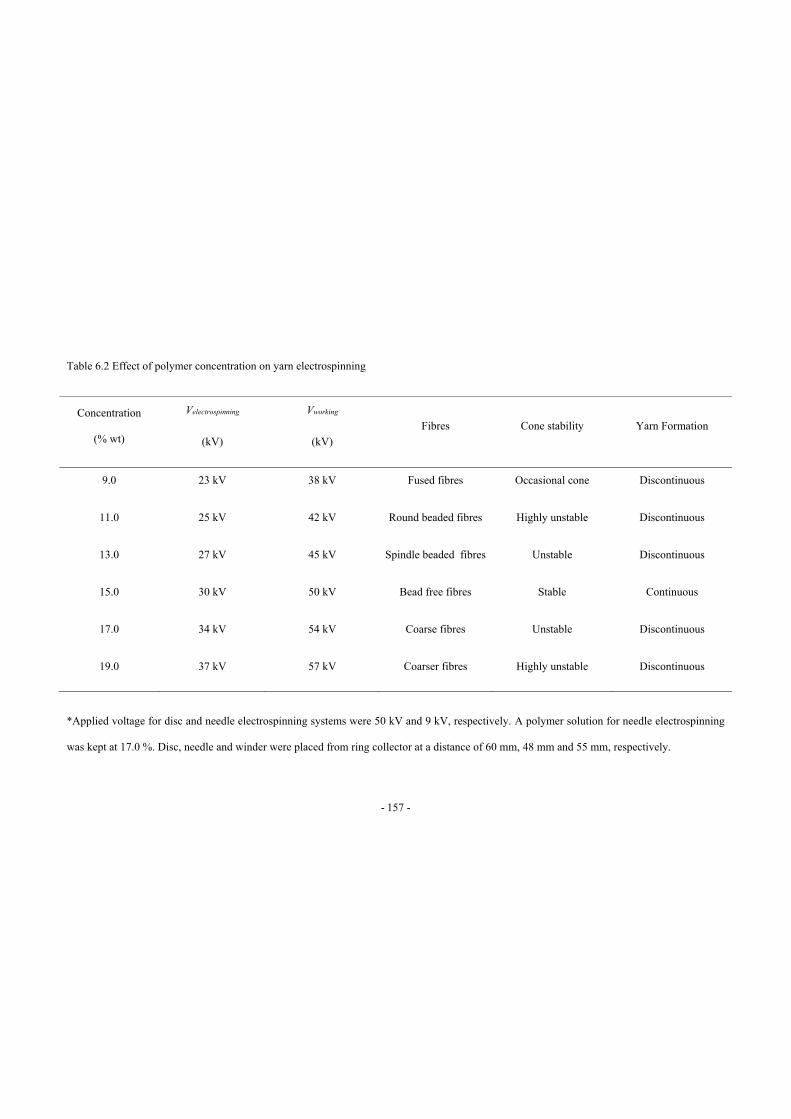
- 157 -
Table 6.2 Effect of polymer concentration on yarn electrospinning
Concentration
(% wt)
Velectrospinning
(kV)
Vworking
(kV)
Fibres Cone stability Yarn Formation
9.0 23 kV 38 kV Fused fibres Occasional cone Discontinuous
11.0 25 kV 42 kV Round beaded fibres Highly unstable Discontinuous
13.0 27 kV 45 kV Spindle beaded fibres Unstable Discontinuous
15.0 30 kV 50 kV Bead free fibres Stable Continuous
17.0 34 kV 54 kV Coarse fibres Unstable Discontinuous
19.0 37 kV 57 kV Coarser fibres Highly unstable Discontinuous
*Applied voltage for disc and needle electrospinning systems were 50 kV and 9 kV, respectively. A polymer solution for needle electrospinning
was kept at 17.0 %. Disc, needle and winder were placed from ring collector at a distance of 60 mm, 48 mm and 55 mm, respectively.
Chapter 6: [Nanofibre Yarn Prepared by Hybrid Electrospinning Systems]
- 158 -
6.3.4 Applied Voltage
Applied voltage plays a pivotal role in nanofibre and yarn production.
The threshold voltage for electrospinning (Velectrospinning) and for the formation of
fibrous cone (Vworking) are listed in Table 6.2. The effect of voltage on nanofibre
generation and yarn formulation was determined by varying the applied voltage
from 0 to 70 kV, keeping polymer concentration at 15.0%. At this condition,
stable cone, bead-free nanofibres, and continuous yarn were produced.
No jets or fibres were produced till the voltage reached 30 kV. At this
point, only a few jets appeared, but the fibres formed were wet and coarse.
Occasionally, wet cone was formed which led to discontinuous yarn production.
The solvent enriched fibres continued to produce even up to 42 kV. Fibrous cone
formed by wet fibres was unstable and yarn broke occasionally during drawing
due to the fused fibrous structure. Once the voltage was above 45 kV, dry fibres
were prepared. Increasing the voltage gradually decreased the number of beaded
and fused fibres.
When applied voltage was increased to 50 kV, plenty of dry nanofibres
were produced which formed steady fibrous cone and continuous nanofibre yarn.
Further increasing the voltage to 60 kV, a number of highly charged nanofibres
were produced. However, a large number of these highly charged fibres flew in
the air other than the target. The fibres which reached target firmly affixed to the
ring collector due to high charges on fibres. As a result, insufficient supply of
nanofibres caused cracked cone and discontinuous yarn.
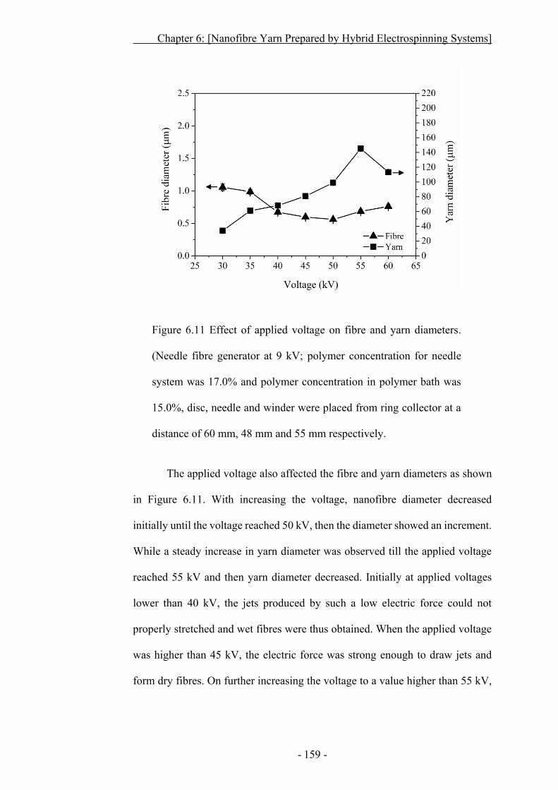
Chapter 6: [Nanofibre Yarn Prepared by Hybrid Electrospinning Systems]
- 159 -
Figure 6.11 Effect of applied voltage on fibre and yarn diameters.
(Needle fibre generator at 9 kV; polymer concentration for needle
system was 17.0% and polymer concentration in polymer bath was
15.0%, disc, needle and winder were placed from ring collector at a
distance of 60 mm, 48 mm and 55 mm respectively.
The applied voltage also affected the fibre and yarn diameters as shown
in Figure 6.11. With increasing the voltage, nanofibre diameter decreased
initially until the voltage reached 50 kV, then the diameter showed an increment.
While a steady increase in yarn diameter was observed till the applied voltage
reached 55 kV and then yarn diameter decreased. Initially at applied voltages
lower than 40 kV, the jets produced by such a low electric force could not
properly stretched and wet fibres were thus obtained. When the applied voltage
was higher than 45 kV, the electric force was strong enough to draw jets and
form dry fibres. On further increasing the voltage to a value higher than 55 kV,
Chapter 6: [Nanofibre Yarn Prepared by Hybrid Electrospinning Systems]
- 160 -
the electric force was so strong that it disturbed the stability and direction of jets.
The fibres produced on such a high voltage were coarse.
Yarn diameter was directly affected by the applied voltage. At voltages
lower than 40 kV, wet fibres fused together and formed smaller diameter yarns.
Yarn produced on higher applied voltages (45 kV≥) constituted of dry well
separated nanofibres. The yarns on such voltages showed gradual increase in
diameter. Although, applied voltages above 55 kV produced dry and well
separated nanofibres, it disturbed jet stability. The fibres produced on such high
voltages went astray. At this point, reduced amount of nanofibres were included
in fibrous cone and yarn diameter showed a declining trend. Moreover, cone
stability was highly unbalanced and yarn fabrication was not steady.
Chapter 6: [Nanofibre Yarn Prepared by Hybrid Electrospinning Systems]
- 161 -
6.3.5 Flow Rate
The amount of polymer solution processed into nanofibres through both
of the electrospinning system was another very critical factor in fibrous cone
development and yarn formation. The polymer flow in needle generator was
controlled through micro-syringe pump, while polymer flow rate from polymer
bath was difficult to control. The polymer coating over disc was partially
controlled by disc generator rotation and applied voltage, yet exact amount of
polymer converted into nanofibres could not be calculated. Disc rotation speeds
from 20~25 rpm helped in evenly loading of polymer solution on disc surface.
The jets produced at this point were evenly distributed and produced dry
nanofibres. At lower speeds (≤ 15 rpm) uneven coating was observed, while
higher speeds (30 rpm ≥) forced more polymer solution on the disc and started
throwing polymer away from disc. Speeds above or below 20 ~ 25 resulted in
irregular jet initiation and wet nanofibre formation.
For a stable cone formation it was necessary to get neutral web over ring
opening, when only disc or needle was producing fibres no proper web was
formed. When polymer flow rate from needle generator was ≤ 1.5 ml/h, not
enough fibres were produced from needle generator to neutralize the positive
fibres coming from disc generator. The web was highly charged and could not
formulate fibrous cone or nanofibre yarn. As the polymer flow rate was increased
to 2.5 ml/h, enough amount of fibres formed a smooth and neutral web on ring
opening. On manually dragging this web to drum winder a very stable cone was
achieved, which resulted in continuous nanofibre yarn formation. Further
increasing polymer flow to 3.0 ml/h and above, polymer dripping was observed.
Chapter 6: [Nanofibre Yarn Prepared by Hybrid Electrospinning Systems]
- 162 -
The fibres produced from needle on such higher polymer flow contained
entrapped solvent and fused fibres. The cone from these fibres, frequently
suffered splitting and adversely affected yarn formation.
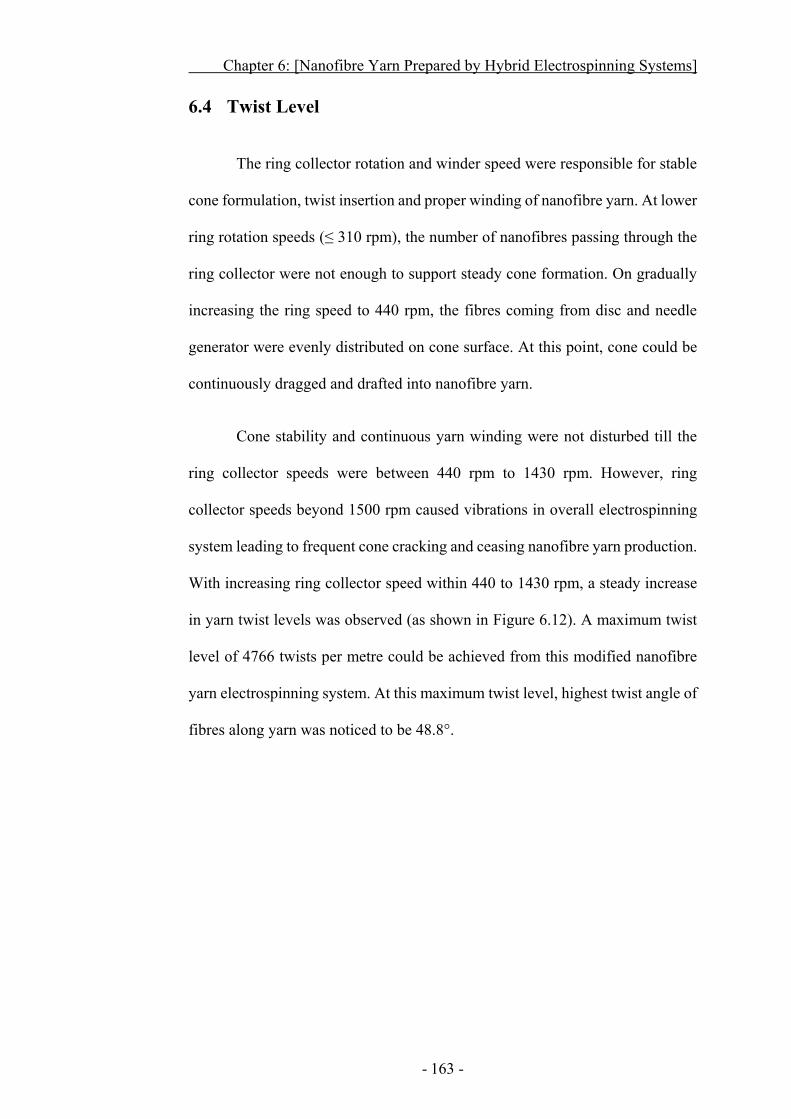
Chapter 6: [Nanofibre Yarn Prepared by Hybrid Electrospinning Systems]
- 163 -
6.4 Twist Level
The ring collector rotation and winder speed were responsible for stable
cone formulation, twist insertion and proper winding of nanofibre yarn. At lower
ring rotation speeds (≤ 310 rpm), the number of nanofibres passing through the
ring collector were not enough to support steady cone formation. On gradually
increasing the ring speed to 440 rpm, the fibres coming from disc and needle
generator were evenly distributed on cone surface. At this point, cone could be
continuously dragged and drafted into nanofibre yarn.
Cone stability and continuous yarn winding were not disturbed till the
ring collector speeds were between 440 rpm to 1430 rpm. However, ring
collector speeds beyond 1500 rpm caused vibrations in overall electrospinning
system leading to frequent cone cracking and ceasing nanofibre yarn production.
With increasing ring collector speed within 440 to 1430 rpm, a steady increase
in yarn twist levels was observed (as shown in Figure 6.12). A maximum twist
level of 4766 twists per metre could be achieved from this modified nanofibre
yarn electrospinning system. At this maximum twist level, highest twist angle of
fibres along yarn was noticed to be 48.8°.
Chapter 6: [Nanofibre Yarn Prepared by Hybrid Electrospinning Systems]
- 164 -
Figure 6.12 Effect of ring speed on twist levels and twist angles
in electrospun nanofibre yarns.
Chapter 6: [Nanofibre Yarn Prepared by Hybrid Electrospinning Systems]
- 165 -
6.5 Yarn Production Rate
Production rate of nanofibre yarns was determined by calculating surface
speed of winding drum. The drum winder was mounted on a small variable speed
motor. The winder speed was varied from 60 to 260 m/hr, to see its effect on
cone stability and y arn formation. It was noted that when winder speed was
lower than 65 m/h, the cone apex was slightly loose, causing jerks and yarn
rupturing at cone apex. Once the speed was increased beyond 90 m/h, a smooth
thick cone was formed and incessant yarn could be produced.
Yarn could be produced without any interruption at maximum winder
speed of 240 m/h. The improvement in yarn production was achieved by
additional nanofibre deposition from both upper and lower sides of the cone. The
disc generator supplied dry nanofibres from disc spinneret, which were evenly
and continuously spread over lower fibrous cone side by ring rotation. While
upper side was augmented by nanofibres coming from the needle generator. A
delicate balance between fibre deposition on cone and drafting of yarn by winder
existed at this stage. At a speed higher than 245 m/h, a lot of attenuation in yarn
and frequent cracks appeared on cone surface, thereby disturbing the balance
between fibre deposition and yarn drafting. On such high speeds, nanofibre
fabrication was not possible.
Chapter 6: [Nanofibre Yarn Prepared by Hybrid Electrospinning Systems]
- 166 -
6.6 Mechanical Properties of Nanofibre Yarns
The mechanical properties of nanofibre yarns were evaluated using
FAVIMAT (AI) + Robot 2. A gauge length of 10 mm and vertical jaw speed of
10 mm/min were employed to test at least 5 samples for each category. Samples
produced from random and aligned web produced under same conditions from
this modified system were also tested to compare overall improvement in
mechanical strength. Typical nanofibre yarn produced by the hybrid system
showed a tensile strength and strain percentage of 128.9 MPa and 222.1%
respectively. Randomly orientated and aligned webs showed a tensile strength
of 9.9 MPa and 22.5 MPa with strain percentage of 98.7 % and 84.6%,
respectively (Figure 6.13a).
Effect of twist levels on nanofibre yarns was also studied. Yarns with
different twist levels were prepared under the same operating condition. It was
found that yarn strength and strain percentage gradually increased with adding
more twists into the yarns, as shown in Figure 6.13b. The increment in twist
levels leads to firmly attached nanofibres and enhanced tensile strength.
Moreover, the number of nanofibres per yarn cross section increased. This
superior fibre to fibre adherence and higher number of nanofibres per yarn cross
section helped in achieving better mechanical properties in nanofibre yarns with
higher twist levels.
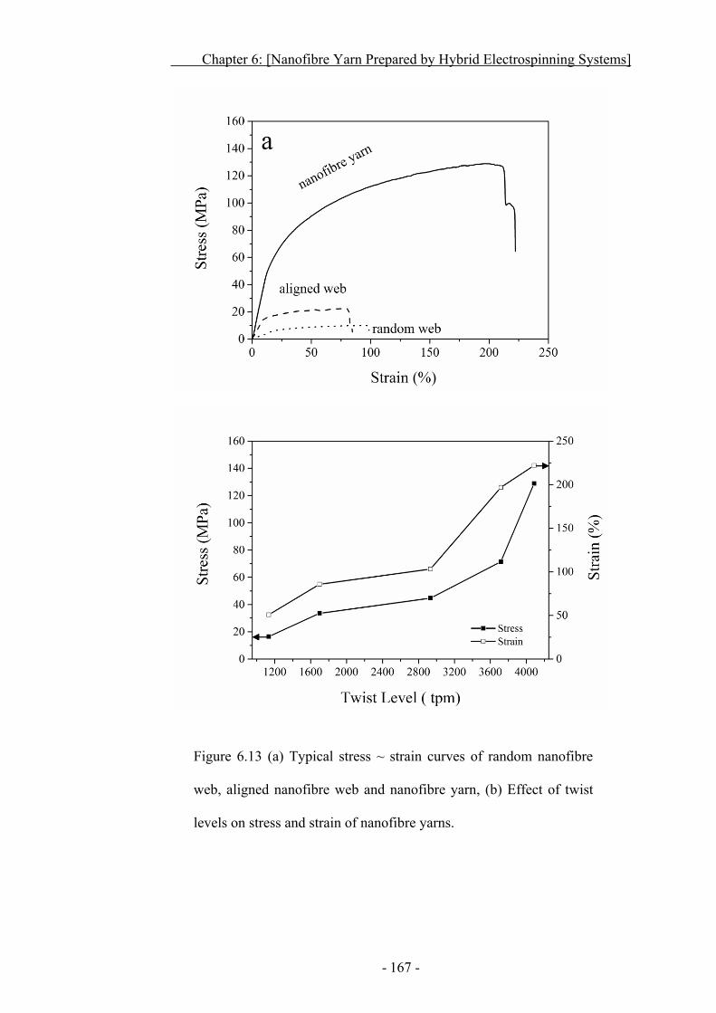
Chapter 6: [Nanofibre Yarn Prepared by Hybrid Electrospinning Systems]
- 167 -
Figure 6.13 (a) Typical stress ~ strain curves of random nanofibre
web, aligned nanofibre web and nanofibre yarn, (b) Effect of twist
levels on stress and strain of nanofibre yarns.
Chapter 6: [Nanofibre Yarn Prepared by Hybrid Electrospinning Systems]
- 168 -
6.7 Conclusion
In this chapter, hybrid electrospinning system was used to fabricate
nanofibre yarns. This hybrid system consisted of a needle and a needleless
nanofibre generators, a ring collector, and a simple drum winder. Effect of
different parameters, such as needle and needleless nanofibre generators and
processing factors on fibre morphology, cone stability and yarn fabrications
were studied.
The distance of different electrospinning elements (nanofibre generator,
needle nanofibre generator and drum winder) was found to be very crucial.
Positions of these electrospinning elements greatly affected the nanofibre
morphology, cone stability and yarn fabrication. At lower distances, there was
not enough time for to get completely dry nanofibres. These wet, coarse fibres
fused together on ring surface, thus no cone nor yarn were formed. Increasing
distance to a suitable point led to dry, well separated fibres. These dry and well
separated fibres helped in achieving highly stable cone and continual withdrawal
of nanofibre yarn. At higher distances, though dry fibres were obtained, they
went off the ring collector.
Parameters from disc fibre generator, including material, diameter and
thickness, were also found to have effects on fibres and yarn diameters. The disc
materials was evaluated for its conductivity and non-conductivity. Non-
conductive HDP (High Density Polyethylene) disc showed evenly distributed
thinner jets with longer life on overall upper disc surface. While conductive discs
(steel, copper and aluminium) produced fewer, thicker jets mostly on disc top.
Chapter 6: [Nanofibre Yarn Prepared by Hybrid Electrospinning Systems]
- 169 -
The disc diameter and thickness affected the nanofibre and yarn
diameters significantly. As the disc diameter was decreased, the number and size
of jets also varied. The smaller the disc, fewer, thicker and irregular were the
jets, which caused diameter of nanofibres increased. The cone stability and yarn
formation were adversely affected by thicker jets producing coarser fibres. The
larger diameter disc produced finer equally spaced jets and nanofibres with lower
diameters resulted in smooth cone and yarn formation.
At a polymer concentrations below 11.0%, fibres with beaded and fused
morphology were produced which ended up on ring surface and no cone or yarn
could be obtained. An increase in polymer concentration to 13.0%, gradually
reduced beads and fused fibres, yet coarser fibres were produced, still no
continuous cone or yarn was produced. At polymer concentration of 15.0%,
plenty of dry and well separated nanofibres rendered to a smooth cone and
continuous fabrication of nanofibre yarn. Beyond 15.0% concentration, the
threshold voltage for nanofibre generation was dramatically increased. On such
concentrations, the fibres still retained solvent and coarser wet fibres were
produced. These wet and fused fibres were generated at higher voltages and
contained higher charges. These fibres either flew off target or stuck to ring
surface. The cone suffered serious shortage of fibres and fibres included were
mostly wet, the cone could not exist and yarn formation ceased.
As at 15.0% polymer concentration, dry and well separated nanofibres
formed a stable cone and incessant yarn, keeping it fixed, the applied voltage
was varied to observe its effect on cone and yarn production. At lower applied
voltages, the electric force was not strong enough to properly stretch jets and wet
Chapter 6: [Nanofibre Yarn Prepared by Hybrid Electrospinning Systems]
- 170 -
fused nanofibres were obtained. These wet fibres did not form cone or yarn. An
applied voltage of 50 kV, demonstrated better fibre morphology, higher cone
stability and increased yarn productivity. Higher voltages did not favour steady
jets and balanced cone formation and yarn manufacturing was discontinuous.
Yarn produced from hybrid system was compared with random and
aligned nanofibre web produced under same conditions. The hybrid yarn showed
improved tensile strength of 128.9 MPa in comparison to aligned (22.5 MPa)
and random web (9.9MPa). The strain % of yarns under test were 222%, 84.6%
and 98.7% for hybrid yarn, random web and aligned nanofibre web. An
increment in twist levels was found to augment tensile properties of nanofibre
yarns. In hybrid electrospinning system, nanofibres were added on both lower
and upper cone surface from disc and needle generator respectively. The cone
formed from hybrid system was thickest and could be drafted at higher speeds
i.e., 240 m/h. This system proved to be more productive and continuous.
The yarn spinner has been developed and tested on laboratory scale.
However, further work on improvement of productivity will allow its application
in industry. With the development of commercial machine for yarn
electrospinning, nanofibre yarn could be used to prepare various fibrous
products for various purposes.
- 171 -
C H A P T E R S E V E N
7 Conclusions and Future Works
7.1 Main Conclusions of Thesis
In this Ph.D. research, a novel ring collector was developed to form
fibrous cone in a separate zone beyond the electrospinning nanofibre generation
site. This not only helped in improving yarn twisting and winding, also restricted
inclusion of beaded, hooked nanofibres. Effect of processing parameters and
material properties on yarn formation were studied. The main conclusions drawn
from this research are as follows:
1) The novel ring collector developed proved to be efficient to isolate
nanofibre generations from yarn twisting and winding. This helped in removing
fused and un-stretched nanofibres from nanofibre yarn. A pair of oppositely
charged needle nanofibre generators, placed near the lower edge of ring
collector, was utilized to produce nanofibres. To get continuous nanofibres, the
negative needle was place at 10 mm from ring collector while positive needle
was kept at 30 mm. The horizontal needle positioning greatly affected the fibre
morphology and continuation in yarn fabrication. Too far distance from needle
tips to ring collector resulted in nanofibre deposition over ring surface and no
cone or yarn was produced. Yarn with coiled nanofibres was obtained when
distance between the needles was further decreased. At an appropriate distance,
a high quality yarn consisting of well aligned and twisted nanofibres was
obtained. Further decreasing needle distance resulted in non-twisted
monofilament yarn.
Chapter 7: [Conclusions And Future Works]
- 172 -
2) By keeping a balance between the ring rotation speed and the winder
speed, a very stable cone could be formed. On continuously twisting and drafting
cone apex, a twisted nanofibre yarn was produced. The yarn twist level could be
varied within a range either by changing ring collector speed or by varying
winding speed. A continuous yarn with maximum twist level of 4086 tpm and
twist angle of 54.4o was obtained from this needle based electrospinning setup,
without disturbing the balance between nanofibre generation and cone
formation. This yarn showed improved tensile properties (93.6 MPa stress and
242.6% strain) in comparison with random-orientated nanofibre nonwoven (9.1
MPa stress and 103.8% strain) and aligned nanofibre web (18.5 MPa stress and
68.3% strain). The increment in twist level helped in achieving yarns with higher
mechanical properties.
3) Coarser nanofibres resulted from increasing polymer solution flow
rate increased polymer concentration, or decreasing winding rate. While
increasing the applied voltage, ring speed and winding rate assisted in reducing
fibre diameter, an optimum polymer concentration and applied voltage were
found to be 17.0% and 13 kV, respectively, while ring rotation. Winding rate of
120 m/h proved to be good enough for collecting smooth, twisted nanofibre yarn.
4) Needleless electrospinning using fibre generators, cylinder, circular
coil, ring and disc was used to produce nanofibres. Cylinder and coil produced
nanofibres had a fused fibrous morphology, while ring collector greatly reduced
fused fibres. The disc generator was found to be the only generator to produce
completely dry, non-fused nanofibres. Moreover, the disc and ring collector
Chapter 7: [Conclusions And Future Works]
- 173 -
produced finer fibres with narrow diameter distribution, while coarser fibres
with broader diameter distribution were obtained from cylinder and coil
generators. Coil generator seemed to be the most efficient in producing
nanofibres, but fibre mat contained wet and fused nanofibres. Although, cylinder
and disc productivities were comparable, the fibres from cylinder generator were
coarser and wet.
5) Needleless electrospinning was used to produce nanofibre yarns. A
polymer concentration of 15.0%, generator to ring distance of approximately 60
mm and applied voltage in the range of 48~58 kV were found to be appropriate
for needleless electrospinning of nanofibres. However, no needleless fibre
generator could formulate stable cone and continuous yarn. By introducing
auxiliary electrode or air jet, only led to small success in nanofibre yarn
preparation.
6) Hybrid electrospinning system composed of both needle and
needleless electrospinning was found to be suitable for production of nanofibre
yarns. The disc/needle system showed the best performance among the hybrid
system. When the applied voltage for the needle and the disc was respectively 9
kV and 50 kV, continuous nanofibres were produced. Nanofibre yarn could be
produced at appropriate positions. The conductivity of disc, disc size and disc
thickness were also important parameters for jet initiation, and determining the
diameters of nanofibres and yarns. Non-conductive disc produced numerous
well-distributed jets with longer life, while conductive disc resulted in fewer,
and thicker jets. The nanofibres formed from non-conductive disc were
Chapter 7: [Conclusions And Future Works]
- 174 -
completely dry and evenly covered the whole ring, whereas fibres from
conductive disc were wet and just deposited unevenly on the ring periphery. The
thinner and larger diameter discs produced larger diameter yarns with finer
nanofibres.
7) The combination of needle and disc electrospinning systems helped in
neutralizing charges over nanofibres and increased amount of nanofibres
inclusion in cone passing through the ring collector. The cone produced from
this hybrid electrospinning system was thicker than other setups. The cone apex
could be dragged and twisted at a substantially high speed. Consequently highly
twisted (4766 tpm) yarns were produced at a large production rate (up to 240
m/h).
7.2 Future Works
Future research in this area could be conducted in the following
directions:
1) Evaluation of the applicability of the yarn electrospinning technique
to other polymers. The work so far carried out in this project mainly
focused on PVDF-HFP. Different materials may lead to difference in
nanofibre yarn formation and mechanical properties.
2) This system is capable of electrospinning different materials
simultaneously. Nanofibre yarn consisting of different polymer
materials can easily be prepared by the yarn electrospinning system
developed.
Chapter 7: [Conclusions And Future Works]
- 175 -
3) Ring collector of different materials, shapes, and sizes should have
effect on nanofibre and yarn formation. How the parameters from
ring collector affect these properties is worthwhile to investigate.
4) An additional air suction or air propulsion system can be installed in
novel electrospinning setup. Such modification might assist in
quickly drying nanofibres. This modification may further improve
the nanofibre morphology and increase yarn productivity.
- 176 -
8 References
1 Bellan LM, Coates GW, Craighead HG. Poly (dicyclopentadiene) submicron fibers produced by electrospinning. Macromol Rapid Commun 2006; 27: 511-515.
2 Ramakrishna S, Fujihara K, Teo WE, Lim TC, Ma Z. An Introduction To Electrospinning And Nanofibers. Singapore: World Scientific; 2005. Available.
3 Wang X, Chen X, Yoon K, Fang D, Hsiao BS, Chu B. High flux filtration medium based on nanofibrous substrate with hydrophilic nanocomposite coating. Environ Sci Technol 2005; 39: 7684-7691.
4 Park JY, Choi S-W, Jung S-H, Kim SS. Synthesis of NiO Nanofibers and Their Gas Sensing Properties. J Nanosci Nanotechnol 2012; 12: 1288-1291.
5 Shi Y, Wei Z, Zhao H, Liu T, Dong A, Zhang J. Electrospinning of Ibuprofen-Loaded Composite Nanofibers for Improving the Performances of Transdermal Patches. J Nanosci Nanotechnol 2013; 13: 3855-3863.
6 Santos LG, Oliveira DC, Santos MS, Neves LMG, de Gaspi FO, Mendonca FA, Esquisatto MA, Santos GM, d'Avila M, Mei LHI. Electrospun Membranes of Poly (Lactic Acid)(PLA) Used as Scaffold in Drug Delivery of Extract of Sedum Dendroideum. J Nanosci Nanotechnol 2013; 13: 4694-4702.
7 Phiriyawirut M, Phaechamud T. Cellulose acetate electrospun fiber mats for controlled release of silymarin. J Nanosci Nanotechnol 2012; 12: 793-799.
8 Li WJ, Laurencin CT, Caterson EJ, Tuan RS, Ko FK. Electrospun nanofibrous structure: a novel scaffold for tissue engineering. J Biomed Mater Res 2002; 60: 613-621.
9 Huang L-Y, Liu T-Y, Liu K-H, Liu Y-Y, Chao C-S, Tung W-L, Yang M-C. Electrospinning of amphipathic chitosan nanofibers for surgical implants application. J Nanosci Nanotechnol 2012; 12: 5066-5070.
10 Kenawy E-R, Abdel-Hay FI, El-Newehy MH, Wnek GE. Processing of polymer nanofibers through electrospinning as drug delivery systems. Mater Chem Phys 2009; 113: 296-302.
11 Wu H, Fan J, Chu C-C, Wu J. Electrospinning of small diameter 3-D nanofibrous tubular scaffolds with controllable nanofiber orientations for vascular grafts. J Mater Sci: Mater Med 2010; 21: 3207-3215.
12 Kosal M. Applying Nanotechnology to Revolutionary Chemical and Biological Countermeasures Nanotechnology for Chemical and Biological Defense. In: Springer New York, 2009. p 29-87.
13 Serp P, Corrias M, Kalck P. Carbon nanotubes and nanofibers in catalysis. Appl Catal, A 2003; 253: 337-358.
14 Wu M-C, Toth G, Sapi A, Leino A-R, Konya Z, Kukovecz A, Su W-F, Kordas K. Synthesis and photocatalytic performance of titanium dioxide nanofibers and the fabrication of flexible composite films from nanofibers. J Nanosci Nanotechnol 2012; 12: 1421-1424.
References
- 177 -
15 Li J, Xie H, Li Y, Wang J. Fabrication of Graphene/Polyaniline Composite for High-Performance Supercapacitor Electrode. J Nanosci Nanotechnol 2013; 13: 1132-1135.
16 Choi SW, Jo SM, Lee WS, Kim YR. An electrospun poly (vinylidene fluoride) nanofibrous membrane and its battery applications. Adv Mater 2003; 15: 2027-2032.
17 Gao K, Hu X, Dai C, Yi T. Crystal structures of electrospun PVDF membranes and its separator application for rechargeable lithium metal cells. Mater Sci Eng B 2006; 131: 100-105.
18 Li C-J, Wang B, Wang J-N. Fabrication Characterization and Activity of a Solar Light Driven Photocatalyst: Cerium Doped TiO2 Magnetic Nanofibers. J Nanosci Nanotechnol 2012; 12: 2522-2528.
19 Ondarçuhu T, Joachim C. Drawing a single nanofibre over hundreds of microns. Europhys Lett 1998; 42: 215-220.
20 Jayaraman K, Kotaki M, Zhang Y, Mo X, Ramakrishna S. Recent advances in polymer nanofibers. J Nanosci Nanotechnol 2004; 4: 52-65.
21 Martin CR. Template Synthesis of Organic Microtubules. J Am Chem Soc 1990; 112: 8976-8977.
22 Ma PX, Zhang R. Synthetic nano-scale fibrous extracellular matrix. J Biomed Mater Res 1999; 46: 60-72.
23 Sarkar K, Gomez C, Zambrano S, Ramirez M, de Hoyos E, Vasquez H, Lozano K. Electrospinning to Forcespinning™. Mater Today 2010; 13: 12-14.
24 Nakata K, Fujii K, Ohkoshi Y, Gotoh Y, Nagura M, Numata M, Kamiyama M. Poly (ethylene terephthalate) Nanofibers Made by Sea–Island Type Conjugated Melt Spinning and Laser Heated Flow Drawing. Macromol Rapid Commun 2007; 28: 792-795.
25 Medeiros ES, Glenn GM, Klamczynski AP, Orts WJ, Mattoso LHC. Solution blow spinning: A new method to produce micro- and nanofibers from polymer solutions. J Appl Polym Sci 2009; 113: 2322-2330.
26 Chen Y, Lin Wang Z, Song Yin J, Johnson DJ, Prince R. Well-aligned graphitic nanofibers synthesized by plasma-assisted chemical vapor deposition. Chem Phys Lett 1997; 272: 178-182.
27 Xiao TD, Strutt ER, Benaissa M, Chen H, Kear BH. Synthesis of high active-site density nanofibrous MnO2-base materials with enhanced permeabilities. Nanostrcut Mater 1998; 10: 1051-1061.
28 Nair S, Tsapatsis M, A. Villaescusa L, A. Camblor M. Zeolite-[small beta] grown epitaxially on SSZ-31 nanofibers. Chem Commun 1999: 921-922.
29 Supothina S, Rattanakam R, Tawkaew S. Hydrothermal Synthesis and Photocatalytic Activity of Anatase TiO2 Nanofiber. J Nanosci Nanotechnol 2012; 12: 4998-5003.
30 Formhals A. Process and apparatus for preparing artificial threads. In: Patent No 1975504, Google Patents, 1934.
31 Formhals A. Method and apparatus for spinning. In: Patent No 2349950, Google Patents, 1944.
32 Margareth G. Nanofibers: Technologies and Developing Markets 2010 [cited 2012 10 Jan 2012]. NAN043B:[Available from:
References
- 178 -
http://www.bccresearch.com/report/nanofibers-technology-market-nan043b.html.
33 Huang ZM, Zhang YZ, Kotaki M, Ramakrishna S. A review on polymer nanofibers by electrospinning and their applications in nanocomposites. Compos Sci Technol 2003; 63: 2223-2253.
34 Johnson J, Ghosh A, Lannutti J. Microstructure property relationships in a tissue engineering scaffold. J Appl Polym Sci 2007; 104: 2919-2927.
35 Lee J, Deng Y. Increased mechanical properties of aligned and isotropic electrospun PVA nanofiber webs by cellulose nanowhisker reinforcement. Macromol Res 2012; 20: 1-8.
36 Deitzel J, Kleinmeyer J, Hirvonen J, Beck Tan N. Controlled deposition of electrospun poly (ethylene oxide) fibers. Polymer 2001; 42: 8163-8170.
37 Okuzaki H, Takahashi T, Hara Y, Yan H. Uniaxially aligned carbon nanofibers derived from electrospun precursor yarns. J Polym Sci Pol Phys 2008; 46: 305-310.
38 Chvojka J, Hinestroza J, Lukas D. Production of Poly (vinylalcohol) Nanoyarns Using a Special Saw-like Collector. FIBRES & TEXTILES IN EASTERN EUROPE 2013; 21: 28-31.
39 Chang G, Shen J. Fabrication of Microropes via Bi-electrospinning with a Rotating Needle Collector. Macromol Rapid Commun 2010; 31: 2151-2154.
40 Gu BK, Shin MK, Sohn KW, Kim SI, Kim SJ, Kim S-K, Lee H, Park JS. Direct fabrication of twisted nanofibers by electrospinning. Appl Phys Lett 2007; 90: 263902-263903.
41 Liu LQ, Eder M, Burgert I, Tasis D, Prato M, Wagner HD. One-step electrospun nanofiber-based composite ropes. Appl Phys Lett 2007; 90: 1-3.
42 Ko F, Gogotsi Y, Ali A, Naguib N, Ye H, Yang GL, Li C, Willis P. Electrospinning of Continuous Carbon Nanotube-Filled Nanofiber Yarns. Adv Mater 2003; 15: 1161-1165.
43 Li X, Yao C, Sun F, Song T, Li Y, Pu Y. Conjugate electrospinning of continuous nanofiber yarn of poly(L-lactide)/nanotricalcium phosphate nanocomposite. J Appl Polym Sci 2008; 107: 3756-3764.
44 Pan H, Li L, Hu L, Cui X. Continuous aligned polymer fibers produced by a modified electrospinning method. Polymer 2006; 47: 4901-4904.
45 Yao C, Li X, Song T. Preparation and characterization of zein and zein/poly L lactide nanofiber yarns. J Appl Polym Sci 2009; 114: 2079-2086.
46 Afifi AM, Nakano S, Yamane H, Kimura Y. Electrospinning of continuous aligning yarns with a 'funnel. Target. Macromol Mater Eng 2010; 295: 660-665.
47 Ali U, Zhou Y, Wang X, Lin T. Direct electrospinning of highly twisted, continuous nanofiber yarns. J Text Inst 2012; 103: 1-9.
48 Yan H, Liu L, Zhang Z. Continually fabricating staple yarns with aligned electrospun polyacrylonitrile nanofibers. Mater Lett 2011; 65: 2419-2421.
References
- 179 -
49 Tan EPS, Lim CT. Physical properties of a single polymeric nanofiber. Appl Phys Lett 2004; 84: 1603-1605.
50 Yang F, Murugan R, Ramakrishna S, Wang X, Ma YX, Wang S. Fabrication of nano-structured porous PLLA scaffold intended for nerve tissue engineering. Biomaterials 2004; 25: 1891-1900.
51 Yang XP, Li XL, Zhang L, Yang QF, Cai Q, Deng XL. Nanofibrosis of uncrystallizable poly(lactide-co-glycolide) via phase separation. Polym Adv Technol 2011; 22: 1078-1082.
52 de Moel K, Alberda van Ekenstein GOR, Nijland H, Polushkin E, ten Brinke G, Mäki-Ontto R, Ikkala O. Polymeric Nanofibers Prepared from Self-Organized Supramolecules. Chem Mater 2001; 13: 4580-4583.
53 Shimizu T, Iwaura R, Masuda M, Hanada T, Yase K. Internucleobase-Interaction-Directed Self-Assembly of Nanofibers from Homo- and Heteroditopic 1,ω-Nucleobase Bolaamphiphiles. J Am Chem Soc 2001; 123: 5947-5955.
54 Hartgerink JD, Beniash E, Stupp SI. Self-Assembly and Mineralization of Peptide-Amphiphile Nanofibers. Science 2001; 294: 1684-1688.
55 Chen Y, Wang ZL, Yin JS, Johnson DJ, Prince RH. Well-aligned graphitic nanofibers synthesized by plasma-assisted chemical vapor deposition. Chem Phys Lett 1997; 272: 178-182.
56 Merkulov VI, Lowndes DH, Wei YY, Eres G, Voelkl E. Patterned growth of individual and multiple vertically aligned carbon nanofibers. Appl Phys Lett 2000; 76: 3555-3557.
57 Fahmi AW, Bruenig H, Weidisch R, Stamm M. Organization of designed nanofibres assembled in filaments via flow alignment. Macromol Mater Eng 2005; 290: 136-142.
58 Ellison CJ, Phatak A, Giles DW, Macosko CW, Bates FS. Melt blown nanofibers: Fiber diameter distributions and onset of fiber breakup. Polymer 2007; 48: 3306-3316.
59 Guan KT, Zhuang XP, Yan GL, Cheng BW. Fabrication and Properties of Polyurethane Nanofibers Nonwoven by Solution Blowing. Adv Mater Res 2011; 332: 1339-1342.
60 Oliveira JE, Moraes EA, Costa RGF, Afonso AS, Mattoso LHC, Orts WJ, Medeiros ES. Nano and submicrometric fibers of poly(D,L-lactide) obtained by solution blow spinning: Process and solution variables. J Appl Polym Sci 2011; 122: 3396-3405.
61 Weitz RT, Harnau L, Rauschenbach S, Burghard M, Kern K. Polymer Nanofibers via Nozzle-Free Centrifugal Spinning. Nano Lett 2008; 8: 1187-1191.
62 Miao M, Shan M, Finn N, Schütz JA, Wood R, Ahern M. Improvement of filtration efficiency by fibre surface nanofibrillation. J Text Inst 2012; 103: 719-723.
63 Gangwal S, Wright M. Nanofibres: New scalable technology platform for producing polymeric nanofibres. Filtration + Separation 2013; 50: 30-33.
64 He J-H, Liu Y, Xu L, Yu J-Y, Sun G. BioMimic fabrication of electrospun nanofibers with high-throughput. Chaos, Solitons & Fractals 2008; 37: 643-651.
References
- 180 -
65 MacDiarmid AG, Jones WE, Norris ID, Gao J, Johnson AT, Pinto NJ, Hone J, Han B, Ko FK, Okuzaki H, Llaguno M. Electrostatically-generated nanofibers of electronic polymers. Synth Met 2001; 119: 27-30.
66 Sundarrajan S, Ramakrishan S. Fabrication of functionalized nanofiber membranes containing nanoparticles. J Nanosci Nanotechnol 2010; 10: 1139-1147.
67 Zhang L, Hsieh Y-L. Ultrafine cellulose acetate fibers with nanoscale structural features. J Nanosci Nanotechnol 2008; 8: 4461-4469.
68 Liu H, Hsieh Y-L. Ultrafine fibrous cellulose membranes from electrospinning of cellulose acetate. J Polym Sci, Part B: Polym Phys 2002; 40: 2119-2129.
69 Wang X, Kim Y-G, Drew C, Ku B-C, Kumar J, Samuelson LA. Electrostatic Assembly of Conjugated Polymer Thin Layers on Electrospun Nanofibrous Membranes for Biosensors. Nano Lett 2004; 4: 331-334.
70 Jiang H, Fang D, Hsiao B, Chu B, Chen W. Preparation and characterization of ibuprofen-loaded poly(lactide-co-glycolide)/poly(ethylene glycol)-g-chitosan electrospun membranes. J Biomater Sci, Polym Ed 2004; 15: 279-296.
71 Matsuda A, Kagata G, Kino R, Tanaka J. Preparation of chitosan nanofiber tube by electrospinning. J Nanosci Nanotechnol 2007; 7: 852-855.
72 Ohkawa K, Cha D, Kim H, Nishida A, Yamamoto H. Electrospinning of chitosan. Macromol Rapid Commun 2004; 25: 1600-1605.
73 Vohra V, Giovanella U, Tubino R, Murata H, Botta C. Electroluminescence from Conjugated Polymer Electrospun Nanofibers in Solution Processable Organic Light-Emitting Diodes. ACS Nano 2011; 5: 5572-5578.
74 Pagliara S, Vitiello MS, Camposeo A, Polini A, Cingolani R, Scamarcio G, Pisignano D. Optical Anisotropy in Single Light-Emitting Polymer Nanofibers. J Phys Chem C 2011; 115: 20399-20405.
75 Mo XM, Xu CY, Kotaki M, Ramakrishna S. Electrospun P(LLA-CL) nanofiber: a biomimetic extracellular matrix for smooth muscle cell and endothelial cell proliferation. Biomaterials 2004; 25: 1883-1890.
76 Xu CY, Inai R, Kotaki M, Ramakrishna S. Aligned biodegradable nanofibrous structure: a potential scaffold for blood vessel engineering. Biomaterials 2004; 25: 877-886.
77 Hou H, Jun Z, Reuning A, Schaper A, Wendorff JH, Greiner A. Poly(p-xylylene) Nanotubes by Coating and Removal of Ultrathin Polymer Template Fibers. Macromolecules 2002; 35: 2429-2431.
78 Wang X, Drew C, Lee S-H, Senecal KJ, Kumar J, Samuelson LA. Electrospun Nanofibrous Membranes for Highly Sensitive Optical Sensors. Nano Lett 2002; 2: 1273-1275.
79 Fong H, Liu W, Wang C-S, Vaia RA. Generation of electrospun fibers of nylon 6 and nylon 6-montmorillonite nanocomposite. Polymer 2001; 43: 775-780.
References
- 181 -
80 Wang X, Lee S-H, Drew C, Senecal KJ, Kumar J, Samuelson LA. Electrospun nanofibrous membranes for optical sensing. Polym Mater Sci Eng 2001; 85: 617-618.
81 Ding B, Kim J, Miyazaki Y, Shiratori S. Electrospun nanofibrous membranes coated quartz crystal microbalance as gas sensor for NH3 detection. Sens Actuators, B 2004; 101: 373-380.
82 Ge JJ, Hou H, Li Q, Graham MJ, Greiner A, Reneker DH, Harris FW, Cheng SZD. Assembly of Well-Aligned Multiwalled Carbon Nanotubes in Confined Polyacrylonitrile Environments: Electrospun Composite Nanofiber Sheets. J Am Chem Soc 2004; 126: 15754-15761.
83 Wang Y, Serrano S, Santiago-Aviles JJ. Conductivity measurement of electrospun PAN-based carbon nanofiber. J Mater Sci Lett 2002; 21: 1055-1057.
84 Li D, Wang Y, Xia Y. Electrospinning of Polymeric and Ceramic Nanofibers as Uniaxially Aligned Arrays. Nano Lett 2003; 3: 1167-1171.
85 Liu H, Kameoka J, Czaplewski DA, Craighead HG. Polymeric Nanowire Chemical Sensor. Nano Lett 2004; 4: 671-675.
86 Von GT, Thomas A, Greiner A, Antonietti M, Weber J. Electrospun silica - polybenzimidazole nanocomposite fibers. Macromol Mater Eng 2008; 293: 815-819.
87 Kim C, Kim YJ, Kim YA. Fabrication and structural characterization of electro-spun polybenzimidazole-derived carbon nanofiber by graphitization. Solid State Commun 2004; 132: 567-571.
88 Mathew G, Hong JP, Rhee JM, Leo DJ, Nah C. Preparation and anisotropic mechanical behavior of highly-oriented electrospun poly(butylene terephthalate) fibers. J Appl Polym Sci 2006; 101: 2017-2021.
89 Catalani LH, Collins G, Jaffe M. Evidence for Molecular Orientation and Residual Charge in the Electrospinning of Poly(butylene terephthalate) Nanofibers. Macromolecules 2007; 40: 1693-1697.
90 Mathew G, Hong JP, Rhee JM, Lee HS, Nah C. Preparation and characterization of properties of electrospun poly(butylene terephthalate) nanofibers filled with carbon nanotubes. Polym Test 2005; 24: 712-717.
91 Tsai P, Schreuder-Gibson HL. The role of fiber charging on co-electrospinning and the resident life of the residual charges from the electrospinning process. Adv Filtr Sep Technol 2003; 16: 340-353.
92 Krishnappa RVN, Desai K, Sung C. Morphological study of electrospun polycarbonates as a function of the solvent and processing voltage. J Mater Sci 2003; 38: 2357-2365.
93 Wei M, Lee J, Kang B, Mead J. Preparation of core-sheath nanofibers from conducting polymer blends. Macromol Rapid Commun 2005; 26: 1127-1132.
94 Raghunath J, Zhang H, Edirisinghe MJ, Darbyshire A, Butler PE, Seifalian AM. A new biodegradable nanocomposite based on polyhedral oligomeric silsesquioxane nanocages: cytocompatibility and investigation into electrohydrodynamic jet fabrication techniques for tissue-engineered scaffolds. Biotechnol Appl Biochem 2009; 52: 1-8.
References
- 182 -
95 Nezarati RM, Eifert MB, Cosgriff-Hernandez E. Effects of Humidity and Solution Viscosity on Electrospun Fiber Morphology. Tissue Eng, Part C 2013; 19: 810-819.
96 Boland ED, Coleman BD, Barnes CP, Simpson DG, Wnek GE, Bowlin GL. Electrospinning polydioxanone for biomedical applications. Acta Biomater 2005; 1: 115-123.
97 Thomas V, Zhang X, Vohra YK. A biomimetic tubular scaffold with spatially designed nanofibers of protein/PDS bio-blends. Biotechnol Bioeng 2009; 104: 1025-1033.
98 Quan S-L, Kang S-G, Qiu Z-C, Chen S-C, Yang K-K, Wang Y-Z, Chin I-J. Characterization of electrospun poly(p-dioxanone) and poly(p-dioxanone)/clay nanocomposite fibers. J Nanosci Nanotechnol 2011; 11: 1609-1612.
99 Abidian MR, Martin DC. Multifunctional nanobiomaterials for neural interfaces. Adv Funct Mater 2009; 19: 573-585.
100 Nguyen HD, Ko JM, Kim HJ, Kim SK, Cho SH, Nam JD, Lee JY. Electrochemical properties of poly(3,4-ethylenedioxythiophene) nanofiber non-woven web formed by electrospinning. J Nanosci Nanotechnol 2008; 8: 4718-4721.
101 Han SO, Son WK, Cho D, Youk JH, Park WH. Preparation of porous ultra-fine fibers via selective thermal degradation of electro spun polyether imide/poly(3-hydroxybutyrate-co-3-hydroxy valerate) fibers. Polym Degrad Stab 2004; 86: 257-262.
102 Reneker DH, Yarin AL, Fong H, Koombhongse S. Bending instability of electrically charged liquid jets of polymer solutions in electrospinning. J Appl Phys 2000; 87: 4531-4547.
103 Fong H, Chun I, Reneker DH. Beaded nanofibers formed during electrospinning. Polymer 1999; 40: 4585-4592.
104 Lin Y, Yao Y, Yang X, Wei N, Li X, Gong P, Li R, Wu D. Preparation of poly(ether sulfone) nanofibers by gas-jet/electrospinning. J Appl Polym Sci 2008; 107: 909-917.
105 Homaeigohar SS, Buhr K, Ebert K. Polyethersulfone electrospun nanofibrous composite membrane for liquid filtration. J Membr Sci 2010; 365: 68-77.
106 Alhusein N, Blagbrough IS, Bank PA. Electrospun matrices for localised controlled drug delivery: release of tetracycline hydrochloride from layers of polycaprolactone and poly(ethylene-co-vinyl acetate). Drug Delivery Transl Res 2012; 2: 477-488.
107 Arinstein A, Liu Y, Rafailovich M, Zussman E. Shifting of the melting point for semi-crystalline polymer nanofibers. EPL 2011; 93: 1-6.
108 Liu Y, Chen S, Zussman E, Korach CS, Zhao W, Rafailovich M. Diameter-Dependent Modulus and Melting Behavior in Electrospun Semicrystalline Polymer Fibers. Macromolecules 2011; 44: 4439-4444.
109 Fasano V, Polini A, Morello G, Moffa M, Camposeo A, Pisignano D. Bright Light Emission and Waveguiding in Conjugated Polymer Nanofibers Electrospun from Organic Salt Added Solutions. Macromolecules 2013; 46: 5935-5942.
References
- 183 -
110 Wang J-J, Dai L-X, Gao Q, Wu P-F, Wang X-B. Electrospun nanofibers of polyferrocenylsilanes with different substituents at silicon. Eur Polym J 2008; 44: 602-607.
111 McDowell JJ, Zacharia NS, Puzzo D, Manners I, Ozin GA. Electroactuation of Alkoxysilane-Functionalized Polyferrocenylsilane Microfibers. J Am Chem Soc 2010; 132: 3236-3237.
112 Wang S, Cao X, Shen M, Guo R, Banyai I, Shi X. Fabrication and morphology control of electrospun poly(γ-glutamic acid) nanofibers for biomedical applications. Colloids Surf, B 2012; 89: 254-264.
113 Tajima T, Ueno S, Yabu N, Sukigara S, Ko F. Fabrication and characterization of poly-γ-glutamic acid nanofiber. J Appl Polym Sci 2011; 122: 150-158.
114 Park KE, Kang HK, Lee SJ, Min B-M, Park WH. Biomimetic Nanofibrous Scaffolds: Preparation and Characterization of PGA/Chitin Blend Nanofibers. Biomacromolecules 2006; 7: 635-643.
115 Boland ED, Wnek GE, Simpson DG, Pawlowski KJ, Bowlin GL. Tailoring tissue engineering scaffolds using electrostatic processing techniques: a study of poly(glycolic acid) electrospinning. J Macromol Sci, Pure Appl Chem 2001; A38: 1231-1243.
116 Ifkovits JL, Devlin JJ, Eng G, Martens TP, Vunjak-Novakovic G, Burdick JA. Biodegradable Fibrous Scaffolds with Tunable Properties Formed from Photocrosslinkable Poly(glycerol sebacate). ACS Appl Mater Interfaces 2009; 1: 1878-1886.
117 Yi F, LaVan DA. Poly(glycerol sebacate) nanofiber scaffolds by core/shell electrospinning. Macromol Biosci 2008; 8: 803-806.
118 Zhu M, Zuo W, Yu H, Yang W, Chen Y. Superhydrophobic surface directly created by electrospinning based on hydrophilic material. J Mater Sci 2006; 41: 3793-3797.
119 Tong H-W, Wang M. Electrospinning of aligned biodegradable polymer fibers and composite fibers for tissue engineering applications. J Nanosci Nanotechnol 2007; 7: 3834-3840.
120 Kim GM, Michler GH, Henning S, Radusch HJ, Wutzler A. Thermal and spectroscopic characterization of microbial poly(3-hydroxybutyrate) submicrometer fibers prepared by electrospinning. J Appl Polym Sci 2007; 103: 1860-1867.
121 Ishii D, Lee W-K, Kasuya K-I, Iwata T. Fine structure and enzymatic degradation of poly[(R)-3-hydroxybutyrate] and stereocomplexed poly(lactide) nanofibers. J Biotechnol 2007; 132: 318-324.
122 Kang W-m, Cheng B-w, Li Q, Zhuang X-p. Morphology of biodegradable poly(hexamethylene adipate) (PHMA) nanofibers prepared by electrospinning. Adv Mater Res 2010; 87-88: 555-560.
123 Sun J, Bubel K, Chen F, Kissel T, Agarwal S, Greiner A. Nanofibers by Green Electrospinning of Aqueous Suspensions of Biodegradable Block Copolyesters for Applications in Medicine, Pharmacy and Agriculture. Macromol Rapid Commun 2010; 31: 2077-2083.
124 Cozzens D, Wei X, Faust R. Electrospinning of biostable polyisobutylene-based thermoplastic polyurethanes. J Polym Sci, Part B: Polym Phys 2013; 51: 452-459.
References
- 184 -
125 Sarkar S, Deevi S, Tepper G. Biased AC electrospinning of aligned polymer nanofibers. Macromol Rapid Commun 2007; 28: 1034-1039.
126 Carroll CP, Joo YL. Electrospinning of viscoelastic Boger fluids: modeling and experiments. Phys Fluids 2006; 18: 053102/053101-053102/053114.
127 Bognitzki M, Hou H, Ishaque M, Frese T, Hellwig M, Schwarte C, Schaper A, Wendorff JH, Greiner A. Polymer, metal, and hybrid nano- and mesotubes by coating degradable polymer template fibers (TUFT process). Adv Mater 2000; 12: 637-640.
128 Kim K, Yu M, Zong X, Chiu J, Fang D, Seo Y-S, Hsiao BS, Chu B, Hadjiargyrou M. Control of degradation rate and hydrophilicity in electrospun non-woven poly(d,l-lactide) nanofiber scaffolds for biomedical applications. Biomaterials 2003; 24: 4977-4985.
129 Kim K, Yu M, Zong X, Chiu J, Fang D, Seo Y-S, Hsiao BS, Chu B, Hadjiargyrou M. Control of degradation rate and hydrophilicity in electrospun non-woven poly(d,l-lactide) nanofiber scaffolds for biomedical applications. Biomaterials 2003; 24: 4977-4985.
130 Luu YK, Kim K, Hsiao BS, Chu B, Hadjiargyrou M. Development of a nanostructured DNA delivery scaffold via electrospinning of PLGA and PLA-PEG block copolymers. J Control Release 2003; 89: 341-353.
131 Min B-M, You Y, Kim J-M, Lee SJ, Park WH. Formation of nanostructured poly(lactic-co-glycolic acid)/chitin matrix and its cellular response to normal human keratinocytes and fibroblasts. Carbohydr Polym 2004; 57: 285-292.
132 Katti DS, Robinson KW, Ko FK, Laurencin CT. Bioresorbable nanofiber-based systems for wound healing and drug delivery: Optimization of fabrication parameters. J Biomed Mater Res, Part B 2004; 70B: 286-296.
133 Chen J-P, Li S-F, Chiang Y-P. Bioactive collagen-grafted poly-L-lactic acid nanofibrous membrane for cartilage tissue engineering. J Nanosci Nanotechnol 2010; 10: 5393-5398.
134 Zeng J, Chen X, Xu X, Liang Q, Bian X, Yang L, Jing X. Ultrafine fibers electrospun from biodegradable polymers. J Appl Polym Sci 2003; 89: 1085-1092.
135 Zong X, Kim K, Fang D, Ran S, Hsiao BS, Chu B. Structure and process relationship of electrospun bioabsorbable nanofiber membranes. Polymer 2002; 43: 4403-4412.
136 Kwon IK, Kidoaki S, Matsuda T. Electrospun nano- to microfiber fabrics made of biodegradable copolyesters: structural characteristics, mechanical properties and cell adhesion potential. Biomaterials 2005; 26: 3929-3939.
137 Mo XM, Xu CY, Kotaki M, Ramakrishna S. Electrospun P(LLA-CL) nanofiber: a biomimetic extracellular matrix for smooth muscle cell and endothelial cell proliferation. Biomaterials 2004; 25: 1883-1890.
138 Murugan R, Huang ZM, Yang F, Ramakrishna S. Nanofibrous scaffold engineering using electrospinning. J Nanosci Nanotechnol 2007; 7: 4595-4603.
References
- 185 -
139 Nikkola L, Seppala J, Harlin A, Ndreu A, Ashammakhi N. Electrospun multifunctional diclofenac sodium releasing nanoscaffold. J Nanosci Nanotechnol 2006; 6: 3290-3295.
140 Kim SJ, Shin KM, Kim SI. The effect of electric current on the processing of nanofibers formed from poly(2-acrylamido-2-methyl-1-propane sulfonic acid). Scr Mater 2004; 51: 31-35.
141 Lee CK, Kim SI, Kim SJ. The influence of added ionic salt on nanofiber uniformity for electrospinning of electrolyte polymer. Synth Met 2005; 154: 209-212.
142 Dong H, Nyame V, MacDiarmid AG, Jones WE, Jr. Polyaniline/poly(methyl methacrylate) coaxial fibers: The fabrication and effects of the solution properties on the morphology of electrospun core fibers. J Polym Sci, Part B: Polym Phys 2004; 42: 3934-3942.
143 Megelski S, Stephens JS, Chase DB, Rabolt JF. Micro- and nanostructure surface morphology on electrospun polymer fibers. Macromolecules 2002; 35: 8456-8466.
144 Xiang H, Zhang L, Wang Z, Yu X, Long Y, Zhang X, Zhao N, Xu J. Multifunctional polymethylsilsesquioxane (PMSQ) surfaces prepared by electrospinning at the sol-gel transition: Superhydrophobicity, excellent solvent resistance, thermal stability and enhanced sound absorption property. J Colloid Interface Sci 2011; 359: 296-303.
145 Luo CJ, Nangrejo M, Edirisinghe M. A novel method of selecting solvents for polymer electrospinning. Polymer 2010; 51: 1654-1662.
146 Okuzaki H, Kobayashi K, Hishiki F, Su S-J, Yan H. Thermo-responsive nanofiber mats fabricated by electrospinning of poly(N-isopropylacrylamide-co-stearyl acrylate). J Nanosci Nanotechnol 2011; 11: 5193-5198.
147 Chen H, Hsieh Y-L. Ultrafine hydrogel fibers with dual temperature- and pH-responsive swelling behaviors. J Polym Sci, Part A: Polym Chem 2004; 42: 6331-6339.
148 Zhang J, Qi H, Wang H, Hu P, Ou L, Guo S, Li J, Che Y, Yu Y, Kong D. Engineering of vascular grafts with genetically modified bone marrow mesenchymal stem cells on poly (propylene carbonate) graft. Artif Organs 2006; 30: 898-905.
149 Welle A, Kroeger M, Doering M, Niederer K, Pindel E, Chronakis IS. Electrospun aliphatic polycarbonates as tailored tissue scaffold materials. Biomaterials 2007; 28: 2211-2219.
150 Srinivasan G, Reneker DH. Structure and morphology of small diameter electrospun aramid fibers. Polym Int 1995; 36: 195-201.
151 Chronakis IS, Grapenson S, Jakob A. Conductive polypyrrole nanofibers via electrospinning: Electrical and morphological properties. Polymer 2006; 47: 1597-1603.
152 Kang TS, Lee SW, Joo J, Lee JY. Electrically conducting polypyrrole fibers spun by electrospinning. Synth Met 2005; 153: 61-64.
153 Koombhongse S, Liu W, Reneker DH. Flat polymer ribbons and other shapes by electrospinning. J Polym Sci, Part B: Polym Phys 2001; 39: 2598-2606.
References
- 186 -
154 Casper CL, Stephens JS, Tassi NG, Chase DB, Rabolt JF. Controlling Surface Morphology of Electrospun Polystyrene Fibers: Effect of Humidity and Molecular Weight in the Electrospinning Process. Macromolecules 2004; 37: 573-578.
155 Lalani R, Liu L. Electrospun zwitterionic poly(sulfobetaine methacrylate) for nonadherent, superabsorbent, and antimicrobial wound dressing applications. Biomacromolecules 2012; 13: 1853-1863.
156 Li Q, Wang Z, Zhao Q, Wang L, Wang S, Kong D. Tissue engineering scaffold electrospun from poly(ϵ-caprolactone)-b-poly(sulfobetaine methacrylate) block copolymers with improved hydrophilicity and good cytocompatibility. e-Polym 2012: 050.
157 Lalani R, Liu L. Synthesis, characterization, and electrospinning of zwitterionic poly(sulfobetaine methacrylate). Polymer 2011; 52: 5344-5354.
158 Kim B-S, Kimura N, Kim H-K, Watanabe K, Kim I-S. Thermal Insulation, Antibacterial and Mold Properties of Breathable Nanofiber-Laminated Wallpapers. J Nanosci Nanotechnol 2011; 11: 4929-4933.
159 Demir MM, Yilgor I, Yilgor E, Erman B. Electrospinning of polyurethane fibers. Polymer 2002; 43: 3303-3309.
160 Theron SA, Zussman E, Yarin AL. Experimental investigation of the governing parameters in the electrospinning of polymer solutions. Polymer 2004; 45: 2017-2030.
161 Ding B, Kim H-Y, Lee S-C, Lee D-R, Choi K-J. Preparation and characterization of nanoscaled poly(vinyl alcohol) fibers via electrospinning. Fibers Polym 2002; 3: 73-79.
162 Wang C, Li ZY, Li D, Yang QB, Hong Y. Preparation and stability of the nanochains consisting of copper nanoparticles and PVA nanofiber. Int J Nanosci 2002; 1: 471-476.
163 Koski A, Yim K, Shivkumar S. Effect of molecular weight on fibrous PVA produced by electrospinning. Mater Lett 2004; 58: 493-497.
164 Bao Q, Zhang H, Yang JX, Wang S, Tang DY, Jose R, Ramakrishna S, Lim CT, Loh KP. Graphene-Polymer Nanofiber Membrane for Ultrafast Photonics. Adv Funct Mater 2010; 20: 782-791.
165 Kim B-S, Song H-M, Lee C-S, Lee S-G, Son Y-A. Preparation of luminescing nanocrystal and its application to electrospinning. Fibers Polym 2008; 9: 534-537.
166 Jannesari M, Varshosaz J, Morshed M, Zamani M. Composite poly(vinyl alcohol)/poly(vinyl acetate) electrospun nanofibrous mats as a novel wound dressing matrix for controlled release of drugs. Int J Nanomed 2011; 6: 993-1003.
167 Park J-Y, Shim W-G, Lee I-H. Modeling and optimization of electrospun polyvinylacetate (PVAc) nanofibers by response surface methodology (RSM). J Nanosci Nanotechnol 2011; 11: 1359-1363.
168 Mu Jo S, Yeon Song M, Rack Ahn Y, Rae Park C, Young Kim D. Nanofibril Formation of Electrospun TiO2 Fibers and its Application to Dye Sensitized Solar Cells. Journal of Macromolecular Science, Part A 2005; 42: 1529-1540.
References
- 187 -
169 Lee KH, Kim HY, Ryu YJ, Kim KW, Choi SW. Mechanical behavior of electro spun fiber mats of poly(vinyl chloride)/polyurethane polyblends. J Polym Sci, Part B: Polym Phys 2003; 41: 1256-1262.
170 Gupta P, Wilkes GL. Some investigations on the fiber formation by utilizing a side-by-side bicomponent electrospinning approach. Polymer 2003; 44: 6353-6359.
171 Baba A, Nakatsukasa T, Baba A, Shinbo K, Kato K, Kaneko F. Fabrication of fluorescence tunable electrospun conjugated polycarbazole fibers containing gold nanoparticles. J Nanosci Nanotechnol 2011; 11: 4289-4294.
172 Kim HS, Lee KB, Lyoo WS. Preparation of high molecular weight poly(vinyl carbazole) web by electrospinning. Polym Polym Compos 2009; 17: 127-132.
173 Balderas U, Falcony C, Moggio I, Arias E, Mondragon M. A photoluminescence study of electrospun fibers of conjugated poly[2-methoxy-5-(2'-ethylhexyloxy)-1,4-phenylenevinylene] blended with poly(9-vinylcarbazole). Polymer 2013; 54: 2062-2066.
174 Choi SW, Jo SM, Lee WS, Kim Y-r. An electrospun poly(vinylidene fluoride) nanofibrous membrane and its battery applications. Adv Mater 2003; 15: 2027-2032.
175 Seoul C, Kim YT, Baek CK. Electrospinning of poly(vinylidene fluoride)/dimethylformamide solutions with carbon nanotubes. J Polym Sci, Part B: Polym Phys 2003; 41: 1572-1577.
176 Ding Y, Zhang P, Long Z, Jiang Y, Xu F, Di W. The ionic conductivity and mechanical property of electrospun P(VdF-HFP)/PMMA membranes for lithium ion batteries. J Membr Sci 2009; 329: 56-59.
177 Park S-H, Kim J-U, Lee S-Y, Lee W-K, Lee J-K, Kim M-R. Dye-sensitized solar cells using polymer electrolytes based on poly(vinylidene fluoride-hexafluoro propylene) nanofibers by electrospinning method. J Nanosci Nanotechnol 2008; 8: 4889-4894.
178 Bansal D, Meyer B, Salomon M. Gelled membranes for Li and Li-ion batteries prepared by electrospinning. J Power Sources 2008; 178: 848-851.
179 Lee Y-S, Collins G, Livingston AT. Neurite extension of primary neurons on electrospun piezoelectric scaffolds. Acta Biomater 2011; 7: 3877-3886.
180 Weber N, Lee YS, Shanmugasundaram S, Jaffe M, Arinzeh TL. Characterization and in vitro cytocompatibility of piezoelectric electrospun scaffolds. Acta Biomater 2010; 6: 3550-3556.
181 Yang Q, Li Z, Hong Y, Zhao Y, Qiu S, Wang C, Wei Y. Influence of solvents on the formation of ultrathin uniform poly(vinylpyrrolidone) nanofibers with electrospinning. J Polym Sci, Part B: Polym Phys 2004; 42: 3721-3726.
182 Li D, Xia Y. Direct Fabrication of Composite and Ceramic Hollow Nanofibers by Electrospinning. Nano Lett 2004; 4: 933-938.
183 Dosunmu O, Chase G, Kataphinan W, Reneker D. Electrospinning of polymer nanofibres from multiple jets on a porous tubular surface. Nanotechnology 2006; 17: 1123.
References
- 188 -
184 Salem D. Electrospinning of nanofibers and the charge injection method: Woodhead Publishing, Cambridge, 2007.
185 Lin Y, Yao Y, Yang X, Wei N, Li X, Gong P, Li R, Wu D. Preparation of poly (ether sulfone) nanofibers by gas jet/electrospinning. J Appl Polym Sci 2008; 107: 909-917.
186 Zhou W, Li Z, Zhang Q, Liu Y, Wei F, Luo G. Gas Flow-Assisted Alignment of Super Long Electrospun Nanofibers. J Nanosci Nanotechnol 2007; 7: 2667-2673.
187 Chu B, Hsiao BS, Fang D, Okamoto A. Electro-blowing technology for fabrication of fibrous articles and its applications of hyaluronan. In: Patent No 2005/033381 A2, Google Patents, 2010.
188 Vaseashta A. Controlled formation of multiple Taylor cones in electrospinning process. Appl Phys Lett 2007; 90: 093115.
189 Paruchuri S, Brenner MP. Splitting of a liquid jet. Phys Rev Lett 2007; 98: 134502.
190 Kong CS, Lee SG, Lee SH, Lee KH, Noh HW, Yoo WS, Kim HS. Electrospinning Instabilities in the Drop Formation and Multi-Jet Ejection Part II: Various Nozzle Diameters for PVA (Polyvinyl Alcohol) Polymer Solution. J Macromol Sci Phys 2011; 50: 528-539.
191 Duby MH, Deng W, Kim K, Gomez T, Gomez A. Stabilization of monodisperse electrosprays in the multi-jet mode via electric field enhancement. J Aerosol Sci 2006; 37: 306-322.
192 Theron S, Yarin A, Zussman E, Kroll E. Multiple jets in electrospinning: experiment and modeling. Polymer 2005; 46: 2889-2899.
193 Kim GH, Cho YS, Kim WD. Stability analysis for multi-jets electrospinning process modified with a cylindrical electrode. Eur Polym J 2006; 42: 2031-2038.
194 Varesano A, Carletto RA, Mazzuchetti G. Experimental investigations on the multi-jet electrospinning process. MATER PROCESS TECH 2009; 209: 5178-5185.
195 Liu Y, Guo L. Homogeneous field intensity control during multi-needle electrospinning via finite element analysis and simulation. J Nanosci Nanotechnol 2013; 13: 843-847.
196 Yarin AL, Zussman E. Upward needleless electrospinning of multiple nanofibers. Polymer 2004; 45: 2977-2980.
197 Jirsak O, Sysel P, Sanetrnik F, Hruza J, Chaloupek J. Polyamic Acid Nanofibers Produced by Needleless Electrospinning. Journal of Nanomaterials 2010; 2010.
198 Liu Y, He JH. Bubble electrospinning for mass production of nanofibers. INT J NONLIN SCI NUM 2007; 8: 393-396.
199 Wang X, Niu H, Lin T. Needleless Electrospinning of nanofibers with a conical wire coil. Polym Eng Sci 2009; 49: 1582-1586.
200 Thoppey NM, Bochinski JR, Clarke LI, Gorga RE. Unconfined fluid electrospun into high quality nanofibers from a plate edge. Polymer 2010; 51: 4928-4936.
201 Tang S, Zeng Y, Wang X. Splashing needleless electrospinning of nanofibers. Polym Eng Sci 2010; 50: 2252-2257.
References
- 189 -
202 Lu B, Wang Y, Liu Y, Duan H, Zhou J, Zhang Z, Wang Y, Li X, Wang W, Lan W, Xie E. Superhigh-Throughput Needleless Electrospinning Using a Rotary Cone as Spinneret. Small 2010; 6: 1612-1616.
203 Wu D, Huang X, Lai X, Sun D, Lin L. High throughput tip-less electrospinning via a circular cylindrical electrode. J Nanosci Nanotechnol 2010; 10: 4221-4226.
204 Thoppey N, Bochinski J, Clarke L, Gorga R. Edge electrospinning for high throughput production of quality nanofibers. Nanotechnology 2011; 22: 345301.
205 Niu H, Lin T, Wang X. Needleless electrospinning. I. A comparison of cylinder and disk nozzles. J Appl Polym Sci 2009; 114: 3524-3530.
206 Niu H, Wang X, Lin T. Needleless electrospinning: developments and performances. In. Nanofibers-Production, Properties and Functional Applications InTech, 2011. p 17-36.
207 Niu H, Wang X, Lin T. Needleless electrospinning: influences of fibre generator geometry. J Text Inst 2012; 103: 787-794.
208 Green TB, King SL, Li L. Fine fiber electro-spinning equipment, filter media systems and methods. In. US2011/0223330 A1, United States: US Patents, 2011.
209 Brettmann BK, Tsang S, Forward KM, Rutledge GC, Myerson AS, Trout BL. Free surface electrospinning of fibers containing microparticles. Langmuir 2012; 28: 9714-9721.
210 Forward KM, Rutledge GC. Free surface electrospinning from a wire electrode. Chem Eng J 2012; 183: 492-503.
211 Forward KM, Flores A, Rutledge GC. Production of core/shell fibers by electrospinning from a free surface. Chem Eng Sci 2013; 104: 250-259.
212 Ding B, Kim HY, Lee SC, Shao CL, Lee DR, Park SJ, Kwag GB, Choi KJ. Preparation and characterization of a nanoscale poly (vinyl alcohol) fiber aggregate produced by an electrospinning method. J Polym Sci Pol Phys 2002; 40: 1261-1268.
213 Sundaray B, Subramanian V, Natarajan T, Xiang RZ, Chang CC, Fann WS. Electrospinning of continuous aligned polymer fibers. Appl Phys Lett 2004; 84: 1222.
214 Teo W, Kotaki M, Mo X, Ramakrishna S. Porous tubular structures with controlled fibre orientation using a modified electrospinning method. Nanotechnology 2005; 16: 918.
215 Dersch R, Liu T, Schaper AK, Greiner A, Wendorff JH. Electrospun nanofibers: Internal structure and intrinsic orientation. J Polym Sci, Part A: Polym Chem 2003; 41: 545-553.
216 Li D, Wang Y, Xia Y. Electrospinning of polymeric and ceramic nanofibers as uniaxially aligned arrays. Nano Lett 2003; 3: 1167-1171.
217 Teo W, Ramakrishna S. Electrospun fibre bundle made of aligned nanofibres over two fixed points. Nanotechnology 2005; 16: 1878.
218 Dalton PD, Klee D, Möller M. Electrospinning with dual collection rings. Polymer 2005; 46: 611-614.
219 Dersch, R., Graeser, M., Greiner, A., Wendorff, H. J. Electrospinning of Nanofibres: Towards New Techniques, Functions, and Applications. Aust J Chem 2007; 60: 719-728.
References
- 190 -
220 Rafique J, Yu J, Yu J, Fang G, Wong KW, Zheng Z, Ong HC, Lau WM. Electrospinning highly aligned long polymer nanofibers on large scale by using a tip collector. Appl Phys Lett 2007; 91: 063126.
221 Bazbouz MB, Stylios GK. Alignment and optimization of nylon 6 nanofibers by electrospinning. J Appl Polym Sci 2008; 107: 3023-3032.
222 Ishii Y, Sakai H, Murata H. A new electrospinning method to control the number and a diameter of uniaxially aligned polymer fibers. Mater Lett 2008; 62: 3370-3372.
223 Liu L, Dzenis YA. Analysis of the effects of the residual charge and gap size on electrospun nanofiber alignment in a gap method. Nanotechnology 2008; 19: 355307.
224 Fong H, Liu W, Wang CS, Vaia RA. Generation of electrospun fibers of nylon 6 and nylon 6-montmorillonite nanocomposite. Polymer 2002; 43: 775-780.
225 Jalili R, Morshed M, Ravandi SAH. Fundamental parameters affecting electrospinning of PAN nanofibers as uniaxially aligned fibers. J Appl Polym Sci 2006; 101: 4350-4357.
226 Paneva D, Manolova N, Rashkov I, Penchev H, Mihai M, Dragan E. Self-Organization Of Fibers Into Yarns During Electrospinning Of Polycation/Polyanion Polyelectrolyte Pairs. DIG J NANOMATER BIOS 2010; 5: 811-819.
227 Maheshwari S, Chang H-C. Assembly of Multi-Stranded Nanofiber Threads through AC Electrospinning. Adv Mater 2009; 21: 349-354.
228 Afifi AM, Nakajima H, Yamane H, Kimura Y, Nakano S. Fabrication of Aligned Poly(L-lactide) Fibers by Electrospinning and Drawing. Macromol Mater Eng 2009; 294: 658-665.
229 Fennessey SF, Farris RJ. Fabrication of aligned and molecularly oriented electrospun polyacrylonitrile nanofibers and the mechanical behavior of their twisted yarns. Polymer 2004; 45: 4217-4225.
230 Moon SC, Farris RJ. Strong electrospun nanometer-diameter polyacrylonitrile carbon fiber yarns. Carbon 2009; 47: 2829-2839.
231 Zhou Y, Fang J, Wang X, Lin T. Strip twisted electrospun nanofiber yarns: Structural effects on tensile properties. J Mater Res 2012; 27: 537-544.
232 Liu, K. C, Sun, J. R, Lai, K., Sun, Q. C, Wang, W. Y. Preparation of short submicron-fiber yarn by an annular collector through electrospinning. Mater Lett 2008; 62: 4467-4469.
233 He CL, Huang ZM, Han XJ. Fabrication of drug-loaded electrospun aligned fibrous threads for suture applications. J Biomed Mater Res A 2009; 89: 80-95.
234 Uddin NM, Ko F, Xiong J, Farouk B, Capaldi F. Process, Structure, and Properties of Electrospun Carbon Nanotube-Reinforced Nanocomposite Yarns. Research Letters in Materials Science 2009; 2009: 1-5.
235 Lotus AF, Bender ET, Evans EA, Ramsier RD, Reneker DH, Chase GG. Electrical, structural, and chemical properties of semiconducting metal oxide nanofiber yarns. J Appl Phys 2008; 103: 024910-024910-024916.
References
- 191 -
236 Lotus AF, Bhargava S, Bender ET, Evans EA, Ramsier RD, Reneker DH, Chase GG. Electrospinning route for the fabrication of p-n junction using nanofiber yarns. J Appl Phys 2009; 106: 14303-14307.
237 Wang X, Zhang K, Zhu M, Yu H, Zhou Z, Chen Y, Hsiao BS. Continuous polymer nanofiber yarns prepared by self-bundling electrospinning method. Polymer 2008; 49: 2755-2761.
238 Mondal A, Borah R, Mukherjee A, Basu S, Jassal M, Agrawal AK. Electrospun self-assembled nanofiber yarns. J Appl Polym Sci 2008; 110: 603-607.
239 Kim HY. Process of preparing continuous filament composed of nanofibers. In: Patent No. PCT/KR04/00188, Google Patents, 2004.
240 Kim HY, Gil MS, Jung YH, Kim HJ, Lee BS. Process of preparing continuous filament composed of nano fiber. In: Patent No PCT/KR03/01460, Google Patents, 2008.
241 Kim HY. Method of manufacturing a continuous filament by electrospinning. In: Patent Number PCT /KR2006/000963, Google Patents, 2010.
242 Khil MS, Bhattarai SR, Kim HY, Kim SZ, Lee KH. Novel fabricated matrix via electrospinning for tissue engineering. J Biomed Mater Res Part B Appl Biomater 2005; 72B: 117-124.
243 Smit E, Bűttner U, Sanderson RD. Continuous yarns from electrospun fibers. Polymer 2005; 46: 2419-2423.
244 Teo W-E, Gopal R, Ramaseshan R, Fujihara K, Ramakrishna S. A dynamic liquid support system for continuous electrospun yarn fabrication. Polymer 2007; 48: 3400-3405.
245 Dabirian, F., Hosseini, Y., Ravandi, Hosseini SA. Manipulation of the electric field of electrospinning system to produce polyacrylonitrile nanofiber yarn. J Text Inst 2007; 98: 237 - 241.
246 Lee JR, Jee SY, Kim HJ, Hong YT, Kim S, Park SJ. Filament Bundle Type Nano Fiber and Manufacturing Method Thereof. In. US2010/0021732 A1, United States: Korea Research Institute of Chemical Technology (Daejun, KR), 2008.
247 Bazbouz MB, Stylios GK. Novel mechanism for spinning continuous twisted composite nanofiber yarns. Eur Polym J 2008; 44: 1-12.
248 Dabirian, F., Hosseini, A. S. Novel method for nanofibre yarn production using two differently charged nozzles. Fibres Test East Eur 2009; 74: 45-47.
249 Dabirian F, Ravandi S, Sanatgar R, Hinestroza J. Manufacturing of twisted continuous PAN nanofiber yarn by electrospinning process. FIBER POLYM 2011; 12: 610-615.
250 Yousefzadeh M, Latifi M, Teo WE, Amani Tehran M, Ramakrishna S. Producing continuous twisted yarn from well aligned nanofibers by water vortex. Polym Eng Sci 2011; 51: 323-329.
251 Ali U, Wang X, Lin T. Direct Electrospinning of Nanofiber Yarns. AATCC Review 2012; 103: 57-63.
252 He J, Qi K, Zhou Y, Cui S. Multiple conjugate electrospinning method for the preparation of continuous polyacrylonitrile nanofiber yarn. J Appl Polym Sci 2013: n/a-n/a.
References
- 192 -
253 Lee JA, Shin MK, Kim SH, Cho HU, Spinks GM, Wallace GG, Lima MD, Lepró X, Kozlov ME, Baughman RH, Kim SJ. Ultrafast charge and discharge biscrolled yarn supercapacitors for textiles and microdevices. Nat Commun 2013; 4: 1970.
254 Kamiyama M, Soeda T, Nagajima S, Tanaka K. Development and application of high-strength polyester nanofibers. Polym J 2012; 44: 987-994.
255 Mirvakili SM, Pazukha A, Sikkema W, Sinclair CW, Spinks GM, Baughman RH, Madden JDW. Niobium Nanowire Yarns and their Application as Artificial Muscles. Adv Funct Mater 2013; 23: 4311-4316.
256 Stankus JJ, Soletti L, Fujimoto K, Hong Y, Vorp DA, Wagner WR. Fabrication of cell microintegrated blood vessel constructs through electrohydrodynamic atomization. Biomaterials 2007; 28: 2738-2746.
257 Zhu Y, Leong MF, Ong WF, Chan-Park MB, Chian KS. Esophageal epithelium regeneration on fibronectin grafted poly (L-lactide-co-caprolactone)(PLLC) nanofiber scaffold. Biomaterials 2007; 28: 861-868.
258 Kim KH, Jeong L, Park HN, Shin SY, Park WH, Lee SC, Kim TI, Park YJ, Seol YJ, Lee YM. Biological efficacy of silk fibroin nanofiber membranes for guided bone regeneration. J Biotechnol 2005; 120: 327-339.
259 Li C, Vepari C, Jin HJ, Kim HJ, Kaplan DL. Electrospun silk-BMP-2 scaffolds for bone tissue engineering. Biomaterials 2006; 27: 3115-3124.
260 Lee IS, Kwon OH, Meng W, Kang IK, Ito Y. Nanofabrication of microbial polyester by electrospinning promotes cell attachment. Macromol Res 2004; 12: 374-378.
261 Li WJ, Danielson KG, Alexander PG, Tuan RS. Biological response of chondrocytes cultured in three dimensional nanofibrous poly (ϵcaprolactone) scaffolds. Journal of Biomedical Materials Research Part A 2003; 67: 1105-1114.
262 Park K, Ju YM, Son JS, Ahn KD, Han DK. Surface modification of biodegradable electrospun nanofiber scaffolds and their interaction with fibroblasts. J Biomater Sci Polym Ed 2007; 18: 369-382.
263 Parlak O, Demir MM. Toward Transparent Nanocomposites Based on Polystyrene Matrix and PMMA-Grafted CeO2 Nanoparticles. ACS Appl Mater Interfaces 2011; 3: 4306-4314.
264 Wang X. Needleless electrospinning of nanofibrous structures. In. Center for Material and Fibre Innovation: Deakin University, Australia, 2010.
265 Niu H. Electrospinning of polymers for functional nanofibres. In: Deakin University, Australia., 2010.
266 Hajiani F, Jeddi AAA, Gharehaghaji A. An investigation on the effects of twist on geometry of the electrospinning triangle and polyamide 66 nanofiber yarn strength. FIBER POLYM 2012; 13: 244-252.
267 He JX, Qi K, Zhou YM, Cui SZ. Fabrication of continuous nanofiber yarn using novel multi nozzle bubble electrospinning. Polym Int 2014.


![Electrospinning for Bone Tissue Engineering · solution electrospinning and melt electrospinning to produce a 3D cell-invasive scaffold has been described [20]. While melt electrospinning](https://img.pdfslide.net/doc/110x75/5e2f2481450bb928ad6e34c6/electrospinning-for-bone-tissue-engineering-solution-electrospinning-and-melt-electrospinning.jpg)