Embed Size (px)
Citation preview
Electrothermal MOSFET ModelsRapid Prototyping of Automotive Electronic Systems
September 2021

public
Introduction
• Andy Berry
• Principal Application Engineer
• Norman Stapelberg
• Senior International Product Marketing Manager
nexperia.com2
public
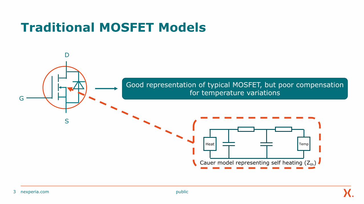
Traditional MOSFET Models
nexperia.com3
D
S
G
Good representation of typical MOSFET, but poor compensation for temperature variations
TempHeat
Cauer model representing self heating (Zth)

public
Traditional MOSFET Models
nexperia.com4
D
S
G
TempHeatTem
p
Hea
t
Cauer model representing self heating (Zth)
public
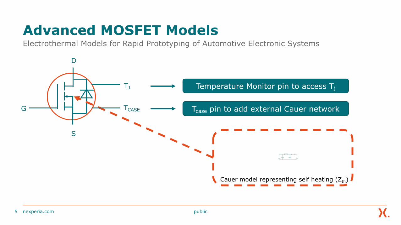
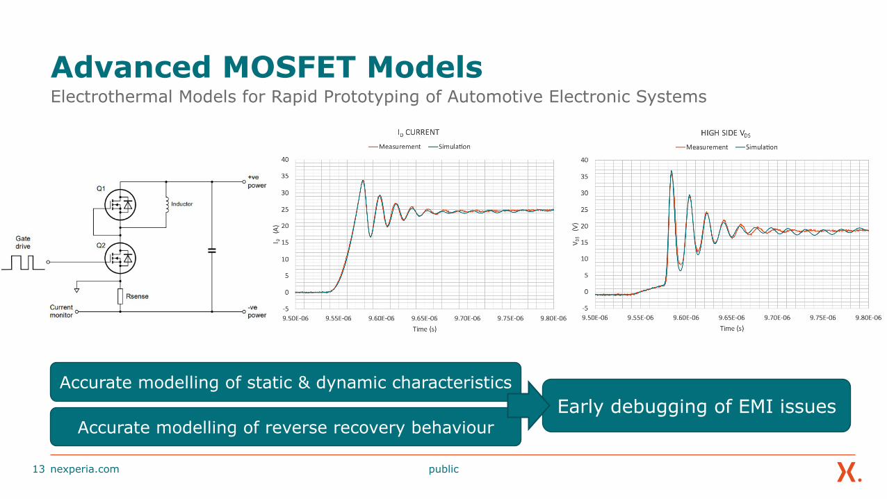
Advanced MOSFET ModelsElectrothermal Models for Rapid Prototyping of Automotive Electronic Systems
nexperia.com5
D
S
G
Tem
p
Hea
t
Cauer model representing self heating (Zth)
Temperature Monitor pin to access TjTJ
TCASE Tcase pin to add external Cauer network
public
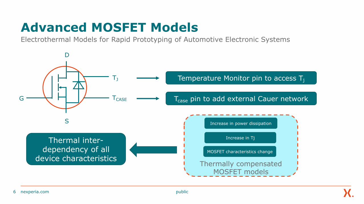
Advanced MOSFET ModelsElectrothermal Models for Rapid Prototyping of Automotive Electronic Systems
nexperia.com6
D
S
G
Temperature Monitor pin to access TjTJ
TCASE Tcase pin to add external Cauer network
Thermal inter-dependency of all
device characteristics Thermally compensated
MOSFET models
Increase in power dissipation
Increase in Tj
MOSFET characteristics change
public
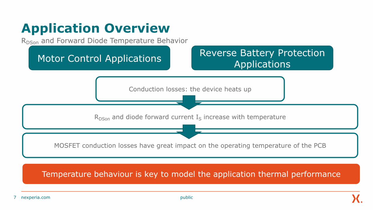
Application OverviewRDSon and Forward Diode Temperature Behavior
nexperia.com7
Motor Control Applications
Temperature behaviour is key to model the application thermal performance
Reverse Battery Protection Applications
Conduction losses: the device heats up
RDSon and diode forward current IS increase with temperature
MOSFET conduction losses have great impact on the operating temperature of the PCB
public
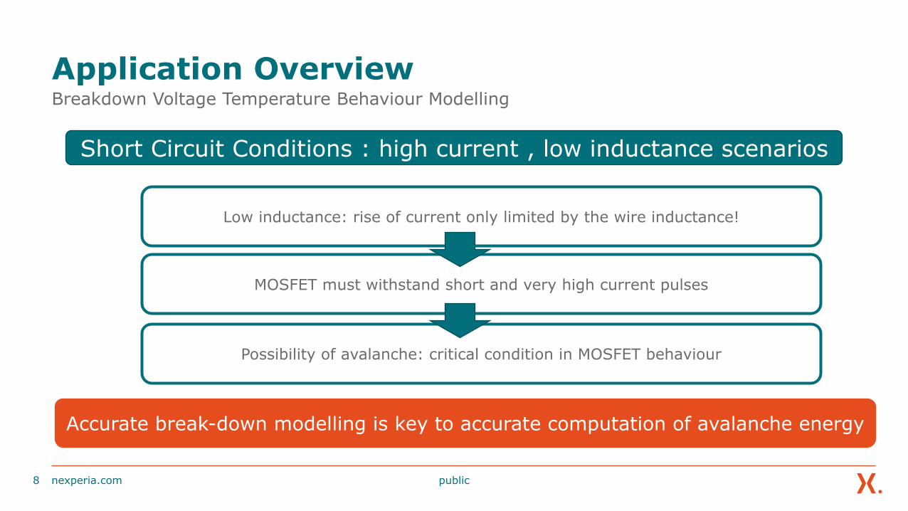
Application OverviewBreakdown Voltage Temperature Behaviour Modelling
nexperia.com8
Short Circuit Conditions : high current , low inductance scenarios
Accurate break-down modelling is key to accurate computation of avalanche energy
Low inductance: rise of current only limited by the wire inductance!
MOSFET must withstand short and very high current pulses
Possibility of avalanche: critical condition in MOSFET behaviour

public
Application OverviewBody Diode Reverse Recovery Modelling
nexperia.com9
Motor Control Applications
During dead-time both MOSFETS are off: free-wheel current flows in the low side body diode
QRR ACCUMULATES
public
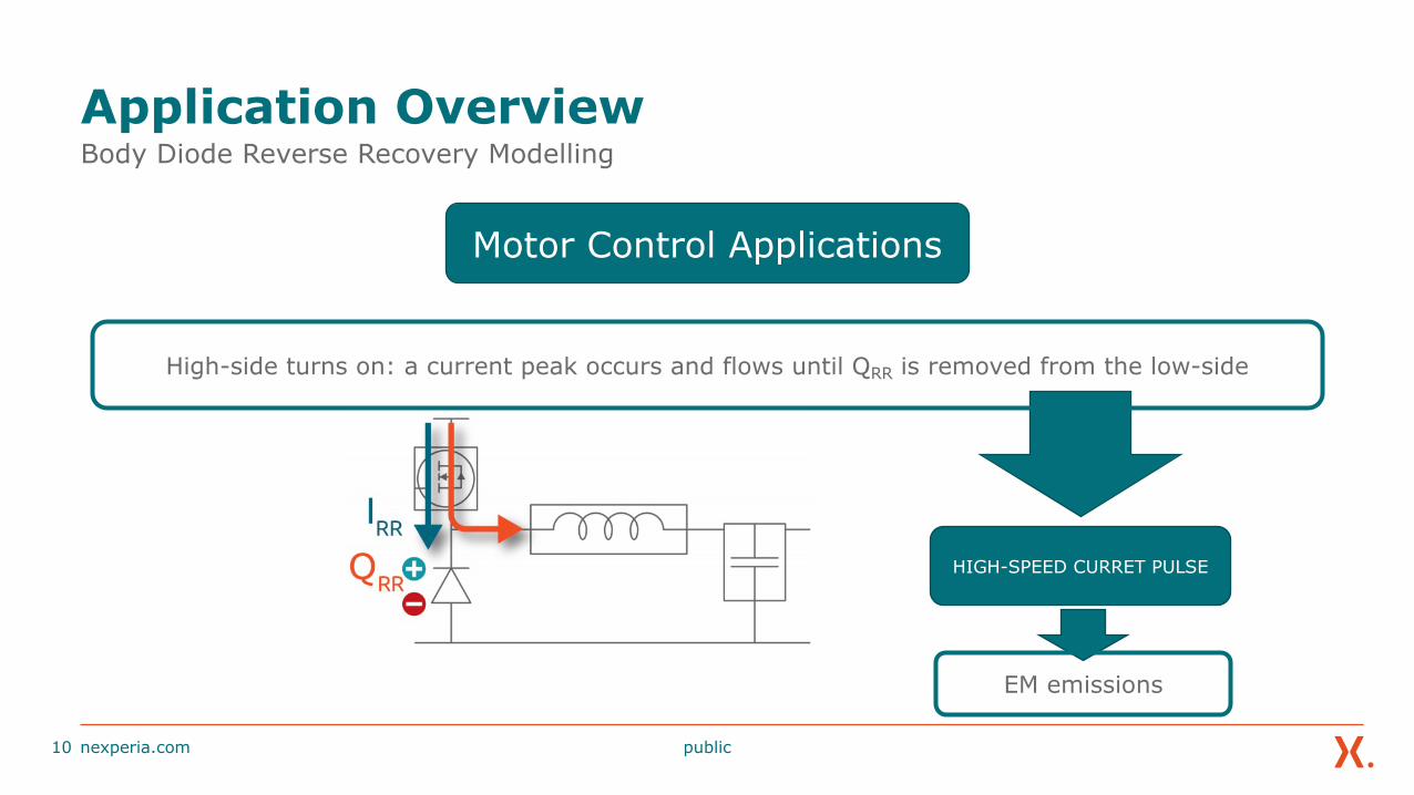
Application OverviewBody Diode Reverse Recovery Modelling
nexperia.com10
Motor Control Applications
High-side turns on: a current peak occurs and flows until QRR is removed from the low-side
HIGH-SPEED CURRET PULSE
EM emissions
public
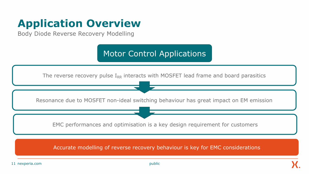
The reverse recovery pulse IRR interacts with MOSFET lead frame and board parasitics
Application OverviewBody Diode Reverse Recovery Modelling
nexperia.com11
Accurate modelling of reverse recovery behaviour is key for EMC considerations
EMC performances and optimisation is a key design requirement for customers
Motor Control Applications
Resonance due to MOSFET non-ideal switching behaviour has great impact on EM emission
public
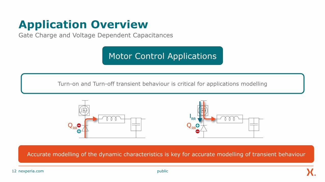
Application OverviewGate Charge and Voltage Dependent Capacitances
nexperia.com12
Motor Control Applications
Turn-on and Turn-off transient behaviour is critical for applications modelling
Accurate modelling of the dynamic characteristics is key for accurate modelling of transient behaviour
public
Advanced MOSFET ModelsElectrothermal Models for Rapid Prototyping of Automotive Electronic Systems
nexperia.com13
Early debugging of EMI issuesAccurate modelling of static & dynamic characteristics
Accurate modelling of reverse recovery behaviour
public
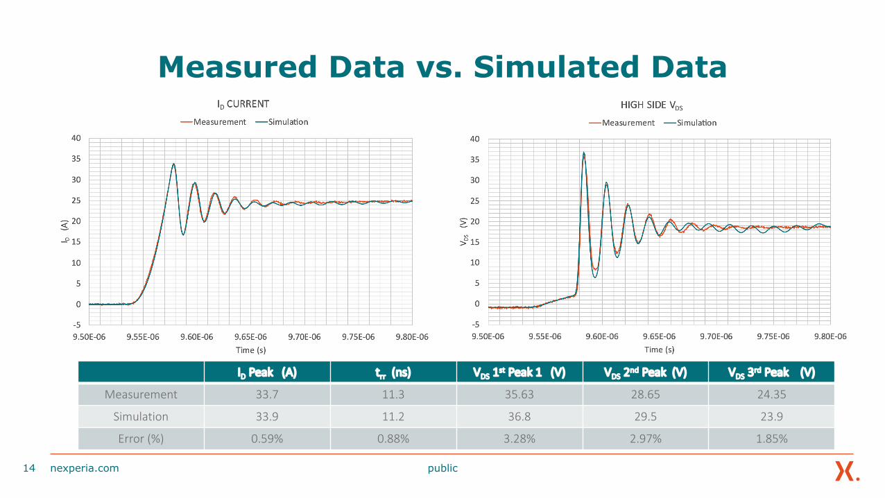
Measured Data vs. Simulated Data
nexperia.com14
ID Peak (A) trr (ns) VDS 1st Peak 1 (V) VDS 2nd Peak (V) VDS 3rd Peak (V)
Measurement 33.7 11.3 35.63 28.65 24.35
Simulation 33.9 11.2 36.8 29.5 23.9
Error (%) 0.59% 0.88% 3.28% 2.97% 1.85%

public
Nexperia Resources
• Models coming soon and will be available on our website
• Please visit nexperia.com/mosfets
nexperia.com15

Please share your questions and insights