Embed Size (px)
DESCRIPTION
PDHLibrary.com - you can take this course on our website by answering 20-40 questions. this course is available for any engineer looking to meet the pdh hours requirement. Engineering PDH - PDHLibrary.comEm 1110-2-3506 - Grouting Technology 1
Citation preview
CECW-EG
EngineerManual
1110-2-3506
Department of the ArmyU.S. Army Corps of Engineers
Washington, DC 20314-1000
EM 1110-2-3506
20 January 1984
Engineering and Design
GROUTING TECHNOLOGY
Distribution Restriction StatementApproved for public release; distribution is unlimited.
DAEN-ECE-G
Engineer ManualNo. 1110-2-3506
Department OF THE AR~U. S. Army Corps of Engineers
Washington, 0. C. 20314
EY 1110-2-3506
20 January 1984
Engineering and DesignGROUTING TECqNOL05Y
1. Purpose. This manual provides technical criteria and gutdance for civilworks grouting applications. Information on procedures, materials, andequipment for use in planning and executing a groutl~g project is included,and types of problems that might be solved by grouting are discussed. MethodSof grouting that have proven to be effective are described and various typesof grouts and their proportions are listed.
2. Applicability. This manual is applicable to all field operatingactivities having civil works responsibilities.
3. Discussion. Grouting in civil works activities is performed as: (a) anincrement of permanent construction, (b) a post-construction remedtaltreatment, and (c) an Increment of expedient construction or repair.
FOR THE COMMANDER:
flColo 1, Corps of EngineersCh f of Staff
E~ineer Manual
No. EM 1110-2-3506
DEPMT~NT OF ~ ARMY ~ 1110-2-3506U. S. Army Corps of EngineersWashington, D. C. 20314
Engineering and DesignGROUTING TECHNOLOGY
Table of Contents
Subject
CHAPTER 1.
CHAPTER 2.
CHAPTER 3.
CHAPTER4.
INTRODUCTION
Purpose and ScopeApplicabilityReferencesChangesGeneral ConsiderationsTerminology
PURPOSES AND LIMITATIONS OF GROUTING
PurposesLimitationsSelection of Methods of
GEOLOGIC CONSIDERATIONSAND DESIGN
Rock TypesStructural GeologyGeohydrologyInvestigation MethodsTest Grouting
PLANNING AND PROCEDURES
ConsiderationsPlanning ConsiderationsQuality ManagementGrout Hole DrillingTypes of TreatmentGrouting tlethodsFoundation Drainage
Treatment
FOR INVESTIGATION
20 January 1984
Paragraph
1-11-21-31-41-51-6
2-12-22-3
3-13-23-33-43-5
4-14-24-34-44-54-64“7
w
1-11-11-11-11-11-1
2-12-12-2
3-13-33-43-63-8
4-14-24-24-34-64-134-19
This manual supersedes EM 1110-2-3501 dated 1 Jul 66 and EM 1110-2-3503dated 19 Aug 63.
i
EM 1110-2-3506
20Jan 84
Subject
CHAPTER 5.
CHAPTER 6.
CHAPTER 7.
CHAPTER 8.
CHAPTER 9.
CHAPTER 10.
GROUT ~TERIALS
Grout MaterialsPortland Cement Grout MixturesSpecial Cements and MixturesMixture AdjustmentsChemical GroutsAsphalt GroutsClay Grouts
EQUIPMENTIntroductionDrilling and Grouting EquipmentSpecial Monitoring Equipmellt
APPLICATION TO WATER RETENTION STRUCTURES
Concrete DamsEarth and Rockfill Dams
APPLICATION TO TUNNELS, SHAFTS, ANDCMBERS
General ApplicationsPurposes of GroutingApplications
APPLICATION TO NAVIGATION STRUCTURES
GeneralFoundation TreatmentRepairsGrout Curtain Through the Lock Area
APPLICATION TO BUILDING FOUNDATIONS
GeneralPregrouting InvestigationSoil StabilizationRock Foundations
CHAPTER 11. PRECISION AND SPECIALTY GROUTING
General StatementScopeApplications
Paragraph
5-15-25-35-45-55-65-7
6-16-26-3
7-17-2
8-18-28-3
9-19-29-39-4
-
5-15-55-95-1o5-145-155-15
6-16-16-29
7-17-5
8-18-18-1
9-19-19-19-2
1o-1 10-110-2 10-110-3 10-110-4 10-3
11-1 11-111-2 11-111-3 11-1
ii
EM 1110-2-350fI
20 Jan 84
Subject
CHAPTER 12.
CHAPTER 13.
CHAPTER 14.
CHAPTER 15.
APPENDIX A.
APPENDIX B.
APPENDIX C.
APPENDIX b.
PERFORMANCE OF WORX
General ConsiderationsContractsHired Labor
FIELD PROCEDURES
General ConsiderationsDrilling OperationGrouting OperationsCompletion of Grouting
METHODS OF ESTIMATING
General ConsiderationsTest GroutingGrouting RecordsEvaluation of Exploration Borings“Unit Take” EstimatesBid Items
RECORDS AND REPORTS
GeneralRecords
REFERENCES AND BIBLIOGRAPHY
ReferencesBibliography
EXAMPLE: FIELD PROCEDURE FORCLARENCE CANNON DAN
PRESSURE COMPUTATION SAMPLES
PHYSICAL CHARACTERISTICS OF SANDED GROUTS
Paragraph
12-112-212-3
13-113-213-313-4
14-114-214-314-414-514-6
15-115-2
A-1A-2
*
12-112-112-1
13-113-113-313-9
14-114-114-114-514-114-2
15-115-6
A-1A-3
B-1
c-1
D-1
iii
EM 1110-2-3506
20Jan 84
CHAPTER 1INTRODUCTION
1-1. -“ This manual provides technical criteria and guidance for civilworks grouting applications. Information on procedures, materials, and equip-ment for use in planning and executing a grouting project is included, andtypes of problems that might be solved by grouting are discussed. Methods ofgrouting that have proven to be effective are described and various types ofgrout and their proportions are listed. The manual discusses grouts composedprimarily of cementitious suspensions and additives although other types arementioned.
1-2. Applicability-. This manual is applicable to all field operating activi-ties responsible for the design and construction of civil projects.
1-3. References. See Appendix A for list of references.
1-4. -“ Users of this manual are encouraged to submit recommendedchanges or comments to ‘improveit. Comments should be keyed to the specificpage, paragraph, and line of the text in which the change is recommended. Rea-sons should be provided for each comment to ensure understanding and completeevaluation. Cements should be prepared using DA Form 2028 (RecommendedChanges to Publications) and forwarded directly to HQUSACE (DAEN-ECE-G) WASH DC20314.
1-5. General Considerations. Grouting in civil works activities is performedas: (a) an increment of permanent construction, (b) a postconstruction re-medial treatment, and (c) an increment of expedient construction or repair.Examples of permanent construction are curtain grouting in the foundations fora dam and ground stabilization of foundation materials for large buildings.%xamples of postconstruction remedial treatment include grouting voids underconcrete structures and reducing leakage through a dam foundation or abutment.Grouting is used for both temporary and permanent treatments. It should beconsidered in combination with other appropriate types of treatment for bestresults. Other types of treatment may include excavation, compaction, con-crete cutoff walls, slurry trenches, impervious blankets, drainage blanketsand filter zones, relief wells, drilled drains, sheet pile cutoff, dental con-crete, grouting and drainage tunnels and galleries, underpinning, and struc-tural foundations. Purposes of expedient grouting include repair of roadwaysand cofferdams, and stability and groundwater control during construction.
1-6. Terminology.
a. Alkali-Aggregate Reaction. Chemical reaction in grout between alka-lies (sodium and potassium) from portland cement or other sources and certainconstituents of some aggregates; under certain conditions, deleterious expan-sion of the grout may result.
1-1
Etl1110-2-350620Jan 84
b. Aquiclude. A body of relatively impermeable rock or soil that iscapable of absorbing water slowly but functions as an upper or lower boundaryof an aquifer and does not transmit groundwater rapidly enough to supply awell or spring.
. Aquifer. A stratum or zone below the surface of the earth capable ofprodu~ing water as from a well.
d. Aquitard. A confining bed that retards but does not prevent the flowof water to or from an adjacent aquifer; a leaky confining bed.
e. Area Grouting. Grouting of a shallow zone in a particular area thatutilizes holes arranged in a pattern or grid. This type of grouting is some-times referred to as blanket or consolidation grouting.
f. Bentonite. A clay composed principally of minerals of the ❑ontmoril-lonite group, characterized by high adsorption and very large volume changewith wetting.
g“ Blanket Grouting. As stated in e above.
h. Bursting Pressure (Grouting Equipment). The pressure at which equip-ment becomes inoperative.
i. Cement Factor. Quantity of cement contained in a unit volume ofgrout, expressed as weight or volume.
j. Cementitious Factor. Quantity of cement and cementitious materialscontained in a unit volume of concrete, grout, or mortar, expressed as weightor volume.
k. Circuit Grouting.lating from the pump to the
P-.
Grouting in a continuous manner with a grout ci-rcu-bottom of the zone to be treated and back to the
1. Coefficient of Permeability (to Water). As stated in ad below.
m. Colloidal Grout. A grout that has an artificially induced cohesive-.—ness, or the ability to retain the dispersed solid particles in suspension;i.e., a grout mixture that does not settle or bleed.
n. Consolidation Grouting. As stated in e above.
o. False Set. The rapid development of rigidity in a freshly mixedgrout without the evolution of much heat. Such rigidity can be dispelled andplasticity can be regained by further mixing without the addition of water.Premature stiffening, hesitation set, early stiffening, and rubber set areother terms that refer to the same phenomenon.
1-2
P. Final Set. A degree of stiffening of a grout mixtureinitial set, generally stated as an empirical value indicatinghours and minutes that is required for cement paste to stiffenresist the penetration of a weighted test needle.
EM 1110-2-350620Jan 84
greater thanthe time insufficiently to
q. Flash Set. The rapid development of rigidity in a freshly mixedgrout, usually with the evolution of considerable heat, and rigidity cannot bedispelled nor can plasticity be regained by further mixing without the addi-tion of water; also referred to as quick set or grab set.
r. Free Water. Water that is free to move through a soil mass under theinfluence of gravity. Other terms are gravitational water, groundwater, andphreatic water.
s. Grout. A mixture of cementitious or noncementitious material, withor without aggregate, to which sufficient water or other fluid is added toproduce a flowing consistency.
t. Grout Placement. The introduction of grout by gravity or pressureinto voids; usually accomplished by grouting through pipes placed in themedium to be grouted or through drilled open holes penetrating the medium.
u. Grout Take. The volume of grout placed.
v. Heat of Hydration, Heat generated by chemical reactions of cementi-tious materials with water, such as that evolved during the setting and harden-ing of portland cement.
w. Hydrofracturing. The fracturing of an embankment or undergroundstrata by pumping water under a pressure in excess of the tensile strength andminor principal stress.
x. Hydrostatic Head. The pressure produced by the height of a fluidabove a given point.
Y. Initial Set. A degree of stiffening of a grout mixture generallystated as an empirical value indicating the time in hours and minutes that isrequired for cement paste to stiffen sufficiently to resist the penetration ofa weighted test needle.
z. Neat Cement Grout. A fluid mixture of cement and water or the hard-ened equivalent of such mixtures. Also called neat slurry.
aa. Packers. Expandable mechanical or pneumatic devices used to seal ahole or isolate portions of a hole.
ab. Perched Groundwater. Any groundwater separated by unsaturated rockfrom an underlying body of groundwater.
1-3
EM 1110-2-350620Jan W
ac. Perched Water Table. The water table above an impermeable bed under-lain by unsaturated rock or soil of sufficient permeability to allow ❑ovementof groundwater.
ad. Permeability (Laboratory) (to Water, Coefficient of). The rate ofdischarge of water under laminar flow conditions through a unit cross-sectionalarea of a porous medium under a unit hydraulic gradien~ and standard tempera-ture conditions, usually 20°C.
. Pore Pressure. Stress transmitted through the pore water (waterfilli~~ voids). Also called neutral stress and pore-water pressure.
af. Pressure Testing. Test performed to measure the rate at which watercan be forced into a hole under a specific pressure.
ag. Pressure Washing. A process of washing between holes to remove mudand loose material from cracks and seams in the rock. In effect, it is asluicing operation whereby water or air and water alternately are introducedunder pressure into a hole and allowed to vent into adjacent cracks or escapefrom one or more adjacent holes.
ah. Primary Hole. The first series of holes to be drilled and grouted,usually at the maximum allcwable spacing.
ai. Primary Permeability. The permeability of intact rock, rather thanpermeability due to fracturing.
aj. Primary Porosity. The porosity that develops during final stages ofsedimentation or that was present within the sedimentary particles at the timeof deposition.
ak. Refusal. The point during grout injection when little or no groutis accepted under the maximum allowable pressure ‘orother specifiedconditions.
al. Secondary Hole. The second series of holes to be drilled andgrouted, spaced midway between primary holes. ,
am. Section. A linear or areal subdivision of the grout treatment pat-tern without regard to the depth of treatment.
an. ~. An area where water oozes from the earth.
ao. Series Grouting. Similar to stage grouting, except each successivelydeeper zone is grouted by means of a newly drilled hole, eliminating the needfor washing grout out before drilling the hole deeper.
ap.holes are
Split Spacing. The procedure by which additional grout injectionlocated equidistant from previously grouted holes.
1-4
EM 1110-2-3506
20 Jan $4
aq. w“ A stage is one complete operational cycle of drilling,cleaning, pressure washing, pressure testing, pressure grouting, and groutcleanout within a zone. Depths of stages in any hole depend on conditionsencountered in drilling that dictate where drilling should stop and groutingcommence.
ar. Stage Grouting. The grouting of progressively deeper zones instages. Previously emplaced grout is removed prior to hardening, the hole isdrilled to a deeper depth, and another stage is emplaced.
Stop Grouting. The grouting of a hole beginning at the lowest zone(bott~~i after the hole is drilled to total depth. Packers are used to iso-late the zone to be grouted.
at. Sulfate Attack. Harmful or deleterious reactions between sulfatesin soil or groundwater and grout.
au. Tertiary Hole. The third series of holes to be drilled and grouted,spaced midway between previously grouted primary and secondary holes.
av. Thixotropy. The property of a material that enables it to stiffenin a short period, on standing, and to regain its initial viscosity by mechan-ical agitation; the process is reversible.
aw. Time of Setting.
(1) Final setting time. The time required for a freshly mixed grout toachieve final set (harden).
(2) Initial setting time. The time required for a freshly mixed groutto achieve initial set.
ax. Unit Weight. The weight of freshly mixed grout per unit volume,often expressed as pounds per cubic foot.
ay. Viscosity. Friction within a liquid due to mutual adherence of itsparticles; i.e., the “thickness” of a mixture.
az. Void Ratio. The ratio of the volume of void space to the volume ofsolid particles in a given soil ❑ass.
ba. Washing. The physical act of cleaning a hole by circulating eitherwater, water and air, acid washes, or water and dissolved chemical substances,through drill rods or tremie pipe in an open hole.
bb. Water/Cement Ratio (Cement Only). The ratio of the amount of waterto the amount of cement in a grout mixture, expressed by weight or volume.
1-5
EM 1110-2-350620Jan 84
bc. Water/Cement Ratio (Total Cementitious Materials). The ratio of theamount of water to the amount of total cementitious materials in a grout mix-ture, expressed by weight or volume.
bd. Water Table. The upper surface of a saturation zone, except wherethat surface is formed by an impermeable body.
be. Working Pressure. The pressure adjudged best for any particular setof conditions encountered during grouting. Factors influencing the determina-tion are size of voids to be filled, depth of zone to be grouted, lithology ofarea to be grouted, grout viscosity, and resistance of the formation to frac-ture or uplift.
bf. Zone. A predetermined subdivision of the overall depth of grouttreatment. A single zone may make up the full depth of treatment, or thedepth of treatment may be divided into several zones.
1-6
EM 1110-2-350620 Jan W
CNAPTER 2PURPOSES AND LIMITATIONS OF GROUTING
2-1. Purposes. Pressure grouting involves the injection under pressure of aliquid or suspension into the voids of a soil or rock mass or into voids be-tween these materials and an existing structure. The injected grout musteventually form either a gel or a solid within the treated voids, or thegrouting process must result in the deposition of suspended solids in thesevoids. The primary purposes of pressure grouting a soil or rock mass are toimprove the strength and durability of the mass and/or to reduce the perme-ability of the mass. This manual provides guidance in the’use of pressuregrouting as a means to improve existing or anticipated subsurface conditions.Information on procedures, materials, and equipment for use in planning andexecuting a grouting project is included, and types of problems that might besolved by pressure grouting are discussed. Methods of pressure grouting thathave proven to be effective are describedtheir properties are listed.
, and various types of grouts and
a. Permeability Reduction. Grouting applications relating to perme-ability reduction include: (1) in association with other measures, reductionof hydrostatic forces acting on the base of water retention structures and ontumel linings; (2) reduction of reservoir water loss; (3) in association withother measures, inhibition of internal erosion of foundation and embankmentmaterials; and (4) facilitation of excavation by stabilization, consolidation,andjor water control. For those applications involving structural safety(i.e. hydrostatic force reduction and erosion inhibition) grouting is not tobe considered as the sole defense. Multiple defenses, such as grouting in as-sociation with drains and/or filters, are to be used.
b. Improvement of Mechanical Properties. Grouting applications relatingto mechanical property improvement include: (1) enhancement of bearing capac-ity, and (2) consolidation of overburden or highly fractured rocks to facili-tate surface or underground excavations.
c. Void Filling. Grouting may be necessary to fill both surface and sub-surface voids.
d. Stabilization and Lifting. Grouting is used for the stabilization offoundations and for lifting and stabilization of footings, slabs, andpavements.
2-2. Limitations. There are two general types of limitations that apply togrouting: (1) limitations inherent in the physical nature of the grouting ma-terials and in the physical and chemical properties of the materials that thegrout will contact, and (2) limitations on grouting operations and methods.Specifically, grouting limitations are delineated in the following paragraphs.
2-1
EM 1110-2-350620Jan 84
a. Physical Limitations. Some physical limitations on cement groutingeffectiveness are:
(1) The maximum and minimum size and geometry of voids to be grouted.
(2) The particle size of the cement, bentonite, or other solid constitu-ents in the grout mix.
(3) The presence of minerals in the groundwater or foundation materialsthat have a detrimental effect on grout strength, setting time, volume, orpermanency.
(4) The possible noncompatibility of grouting materials used in the ❑ix.
(5) The presence of clay or other erodible materials in the foundationthat cannot be completely removed by washing.
(6) Settlement of cement particles from suspension in the grout.
(7) The presence of unknown subsurface features or conditions detri-❑ental to the grouting program.
b. Limitations. Examples of limitations to grouting effectiveness re-lated to field operations and methods include:
(1)
(2)
(3)turely or
(4)
(5)
Uplift and damage to foundations resulting from excessive pressures.
Use of improper drilling and grouting equipment.
Improper plugging of foundation voids by thickening the mix prema-by unsuitable injection methods.
Improper hole spacing or orientation of grout holes.
Failure to utilize experienced geological and inspection personnelto supervise and inspect drilling and grouting operations.
2-3. Selection of Methods of Treatment. Grouting is one method of treatingsubsurface materials to reduce permeability or improve strength and stability.However, other methods of treatment ❑ay be required in addition to or in lieuof grouting. As stated, where structural safety is involved, the multiple de-fense approach will be required. The selection of grouting as the method oftreatment should be based on an evaluation of all pertinent aspects of theproblem, including engineering needs, subsurface conditions, and economicconsiderations.
2-2
EM 1110-2-350620 Ja? 84
CNAPTER 3GEOLOGIC CONSIDERATIONS FOR INVESTIGATION AND DESIGN
3-1. Rock Types. The differing properties of various rock types by nature oftheir origin, lithology, and structure will influence the grouting conditionsat a particular site. A thorough knowledge of the rock types present at thesite, and their geologic history, is therefore essential for the design andtreatment of the foundation. The exploration and grouting programs must beadapted to the site geologic conditions. Different rocks with the same gen-eral fracture permeability and void characteristics can be loosely groupedtogether. Examples of some of the more common rock types are listed, togetherwith those general characteristics that could influence required foundationtreatment.
a. Crystalline. Crystalline rock is an inexact but ’convenientterm thatidentifies igneous and metamorphic as opposed to sedimentary rocks.
(1) Intrusive igneous rocks include granites, syenites, diorites, andgabbros. Some features commonly found in these rocks are sheet jointing,shear zones, dikes, and sills.
(2) Jointing in three directions is characteristic of intrusive. Oneset is usually near-horizontal (sheet or uplift jointing), and the other twoare near-vertical and generally normal to each other. The spacing of sheetjoints is frequently close near the surface but increases with depth.
(3) Grout take normally occurs in the joints and the fractures, and thevolume is dependent on the size and continuity of the openings along the frac-tures. Certain metamorphic rocks such as gneisses would react in a mannersimilar to that of the granites. Grout takes in schists and slates are de-pendent on the ~resence and characteristics of associated jointing or finefracturing. Most quartzites are highly fractured and would readily acceptgrout. Marble is a crystalline rock but should also be considered in thecategory of karstic formations since solution cavities should be anticipated.
b. Volcanics. Volcanics generally include the extrusive igneous rocks.Felsites, a group of very dense, fine-grained rocks, are extrusive and near-surface equivalents of granites, syenites, and other related crystalline rocks.In addition to granite-like jointing they may also exhibit columnar structure.Basalts are a group of very dense, dark, igneous rock. The jointing may beplaty or columnar. Basalts in many flows commonly exhibit columns with threeto six sides. Pumice and scoria are often associated with basalts. Pyro-clastics, such as agglomerates and tuffs, are materials formed by explosivevolcanic activity and consist of fragments torn loose by such explosions, ordeposits of wind-borne ash. Large-scale engineering operations in pyroclasticrocks are ~enerallv difficult. Volcanics require extensive examination before.engineering characteristicstreatment. The presence of
can be determined and will usually require specialcolumnar jointing in lava flows tends to lower the
3-1
EM 1110-2-350620Jan 84
strength of the mass as a whole, and extensive grouting can be expected. Per-meabilities may be great in lava flows due to the extensive jointing whichnormally is present and due to the presence of piped vesicles and gas cavities.These features may transmit copious flows of water. In some cases, however,the joints are tight and/or filled and the rock mass may have a very low per-meability. Each case must be evaluated individually to determine the need forand effectiveness of grouting.
c. Soluble Rocks. Limestone, dolomite, gypsum, anhydrite, and haliteare i~cluded in this group. The principal defect in this rock group is volu-bility in varying degrees that can ultimately cause high mass permeability,slump, collapse, and sinks~’resulting in karst topography.
(1) Limestones and dolomites are the most widespread of the soluble sedi-ments. These rocks may be vuggy and may display a wide range of permeabilityas a unit. Limestone and dolomite are generally jointed and usually exhibittwo or three distinct sets of jointing. Solutioning is frequently well de-veloped along bedding planes and joints, and contacts with other rock types.Joints and cavities may be either filled or open and the sizeDependent upon the extent of jointing and cavities, extensivegrouting can be anticipated.
(2) Anhydrite is pure calcium sulfate whereas gypsum isform. Both are soft and fairly soluble in water. Both typesand have a varying number and size of solution cavities. Theare filled with clay or other reworked material. Grout takespresence and characteristics of the joints and cavities.
may vary greatly.treatment and
the hydratedmay be jointedcavities oftendepend on the
(3) Halite (rock salt) is soft and soluble in water. The ext~emelysoluble halite is not found in outcrop but may be found at depth. The princi-pal engineering significance of halite is the effect its presence or proximitymay have on the proposed project, such as solutioning and subsidence, in addi-tion to effects on groundwater.
(4) Grouting in solutioned limestone and dol~ite often meets with amixed degree of success. Grouting will frequently dramatically reduce initialseepage. However, the seepage often has a tendency to increase with timeafter grouting is completed. The increased seepage is attributed to the ero-sion of void-filling materials that were not adequately removed before grout-ing. The erosion or piping of this unconsolidated material creates seepagewindows in the grout curtain that become progressively larger and more pro-lific with time.
d. Clastic Sedimentary Rocks. Conglomerates, sandstones, siltstones,and shales are the principal types of elastic sedimentary rocks. The physicalproperties of sandstone, siltstone, and conglomerate depend on the degree andtype of cementation. These coarser elastics may be tight and impermeable, ormay be sufficiently porous and permeable to need treatment. Jointing would be
3-2
EM 1110-2-350620Jan W
the main concern in impermeable elastics as to need for treatment. The finerelastics, such as claystones and shales, are made up of clay minerals, variousoxides, silica, fine particles of ordinary minerals, and some amount of col-loidal and organic materials. These elastics may contain a great amount ofwater. Two shale types are cementation shale and compaction shale. Compac-tion shales usually contain no joints capable of being grouted. Cementedshales are more resistant to change and have engineering properties superiorto those of the compaction type. Cemented to slightly metamorphosed shalesare sufficiently brittle to react to structural changes and develop jointssimilar to those in sandstone.
e. Unconsolidated Materials. Unconsolidated materials include residualoverburden derived from the weathering of the parent rock. Residual soils arein situ as opposed to transported sediments. The properties of the materialsreflect to a certain extent the properties of the original material. Finerderivations of the parent rock, such as clays and silts, are generally impervi-ous and would not require grouting. However, in certain instances where solu-ble rocks underlie the overburden, voids or very soft and loose materialcaused from the collapse of the overburden into the solution channels may re-quire treatment. Transported sediments may include outwash deposits and al-luvial deposits generally found in stream valleys, terrace deposits, and mostglacial deposits. If the project design does not require removal of these de-posits, grouting or other treatment may be required to reduce or control per-❑eability and improve stability. Soil samples should be investigated by labo-ratory tests for permeability, gradation, and density.
3-2. Structural Geology.
a. Structure. The term “rock structure” refers to the spatial relation-ships of rocks and their discontinuitiesmany ways.
, and affects engineering projects inFolds and faults influence the selection of dam sites, and even
such seemingly small matters as the spacing of joints may have an importantbearing on the distribution of uplift pressures.
b. Folds. A common type of deformation is folding. The folded rocksoften show considerable fracturing along the axis of the fold. The severityof engineering problems is dependent upon the complexity of the fold with re-lation to the type and geometry of the proposed structures and would includeexcavation, stability, and leakage problems.
c. Faults. Faults are fractures along which masses of rock have beenmoved in a direction parallel to the fault surface. The movement may varyfrom a few centimeters or less to many kilometers.
(1) Faults very rarely show a clean and uncomplicated break. The rockswill normally exhibit folding, fracturing, crushing, and grinding. Sometimesthe wallsThe rocks
exhibit polished and smoothly striated surfaces called slickensides.on the opposite sides of the fault surface may occasionally be
3-3
EM 1110-2-350620 Jan M
broken into angular fragments referred to as fault breccia. In addition tothese mechanical effects, faults may result in channels for circulating wateror may be impermeable and form groundwater barriers.
(2) Recognition of faults is of great importance because faults repre-sent zones of weakness in the crust of the earth, and the presence of thesezones would affect the engineering properties of a site, including seismologi-cal considerations, excavation, tunnel support, dam stability, and leakageproblems.
d. Joints. Joints are almost universally present and are of consider-able engineering importance for that reason. Joints offer channels for ground-water circulation, and joints below the groundwater table may greatly increasewater problems. Joints may also exert an important influence on weatheringand excavation characteristics.
e. Grouting Considerations. Since many rock types have a low primarypermeability but a relatively high fracture and joint permeability, the im-portance of grouting the structural defects is apparent. The type of struc-tural feature (e.g. fault, fold, joint) will dictate to a large extent thetype and extent of excavation treatment and the grouting methods. The spacingand nature of the fractures (e.g. open, weathered, solutioned) influence thetype of grout treatment selected, such as consolidation grouting and curtaingrouting. The selection of a single-line or multiple-line curtain and thegrout hole spacing are also affected. The orientation (dip and strike) ofthese features in relation to a structure influences the planned angle anddirection of the grout holes and the drain holes. The depth of the fracturesaffects the depth of a grout curtain. The grout holes should intersect allthe features, and each inclined or vertical feature should ideally be inter-sected by several holes at different depths. Faults may be gouge filled andimpermeable, thereby forming a barrier, or may be open and carry groundwater.Joints may be filled or open, may have weathered or nonweathered faces, andmay intersect and be connected over a wide area. The condition of the jointswould affect the drilling, the cleaning, the pressure testing, and the grout-ing of the hole. Since structural features influence the grouting program soprofoundly, the site exploration should be sufficiently thorough to base thedesign on actual site conditions.
3-3. Geohydrology. Almost all engineering projects are affected by subsur-face water. The importance of subsurface water is especially obvious in re-spect to water retention structures. A thorough understanding of the regionaland site specific groundwater conditions is necessary to safely design, con-struct, and operate these projects. A brief discussion of a few generalprinciples follows. Application of the principles to specific problems suchas foundation treatment and grouting can”then be determined.
a. Porosity and Permeability. Almost all rocks contain pore spaces tosome extent. To be permeable, however, pore spaces in rock must be
3-4
interconnectedsandstones are
EM 1110-2-350620 Ja? M
and sufficiently large to allow the passage of water. Mostboth porous and permeable. Shale, on the other hand, has a
high porosity but the pores are limited to capillary sizes and water passagethrough the shale is extremely slow. Although intact shale is porous but im-permeable, joints and other fractures permit the passage of water even thoughthe water cannot readily pass through the interior of the joint-bounded rocks.Even in regions where the bedrock is granite or a similarly massive and imper-meable rock, water occurs in fractures at least in limited quantities and tosome depth. Understanding the nature of the joint system is of crucial im-portance in areas such as these.
b. Groundwater.
(1) Groundwater is the water in the zone of saturation. The upper limitof this zone is referred to as the water table. The depth to the water tablemay vary considerably depending on site conditions. The groundwater may befound either in continuous bodies or in several separate strata, and the thick-ness may vary considerably. Local saturated zones that may occur above themain water table are termed perched water.
(2) Local geology, permeability of the formations, including solutioningand fracturing, and recharge and movement within the zone are factors that af-fect aquifer characteristics. Any mass of permeable rock material from whicha significant amount of water can be recovered is called an aquifer. Aquifersmay be unconfined or confined. An unconfined aquifer occurs when the upperlimit of the aquifer coincides with the water table, since the surface of thewater is at atmospheric pressure. The hydraulic pressure at any level underthis system is the same as the depth from the water table to the subject depthand may be expressed as hydraulic head in feet of water. Water under artesianconditions is under hydrostatic pressure and therefore rises in a well. Whenthe pressure is sufficient to bring the water above the ground surface, aflowing artesian well occurs. Water that rises only to an intermediate levelis a nonflowing artesian well. .
(3) Artesian water also occurs in a similar fashion in jointed bedrock.Certain sets of joints may be more openly developed, and a large amount ofwater may gather in the joints under artesian conditions. A drill may passthrough a few hundred feet of impermeable rock in which the joints are few andtightly closed. When the permeable, jointed zone is reached, the hydrostaticpressure at that depth causes the water to rise. The number of joints, aswell as the degree of opemess, normally decreases with depth, and the chance.of penetrating a water-bearing zone is generally greatest in the upper portionof the bedrock.
c. =“ Any natural surface emergence of water from a subterraneancourse is a spring. Many small springs represent water from rain or snow fromhigher ground that moves under gravitational force to a place of emergence.The course and flow rate of a spring depend on the permeability and structure
3-5
EM 1110-2-350620Jan W
of the material through which the water moves. Some springs flow upward witha measurable force, indicating that they are under pressure. Springs are mostcommon in sandstones, cavernous carbonate rocks, vesicular lava flows, andhighly jointed or fractured rocks of any kind. Some of the largest springsdevelop along the borders of karst regions.
d. Water Quality. The quality of the groundwater is primarily due tothe mineralogical character of the reservoir rocks and their degree of volu-bility in water. The groundwater in limestone areas usually contains a largeproportion of dissolved carbonates. Rock salt (halite) furnishes a readysource of chlorides, while gypsums and anhydrites supply quantities of sul-fates. Water containing humic and other acids, dissolved sulfates, chlorides,and similar chemicals may act corrosively on steel and iron and may be in-jurious to grout and concrete. Ferrous iron in water may oxidize into an un-sightly limonitic stain in certain cases. Iron may also lead to developmentof growths of iron bacteria. The source of the ferrous iron is generallyrocks that contain pyrite or marcasite (iron sulfides). These minerals arecommon in many shales, especially carbonaceous shales. Water from suchsources may also contain hydrogen sulfide. In areas where coal mining has oc-curred, both ground and surface water may be highly acidic.
e. Grouting Considerations.
(1) Since groundwater conditions have an important effect on design andconstruction, the regional and local conditions must be studied during the in-vestigation stages so that potential’problems may be evaluated. The groutingprogram should be designed for the existing groundwater conditions as well asfor postconstruction conditions. Different methods and procedures may be em-ployed, depending on the formation permeability, the depth to water table, andthe type of aquifer present (confined and unconfined). These conditionsaffect the type of grout, the grouting procedure, the depth and extent oftreatment, the spacing of holes, the need for a multiple- or single-line groutcurtain, and the pressures that should be used.
(2) Aquifer conditions also have a direct bearing on the need for andtype of drainage required. The chemistry of the groundwater should be con-sidered with respect to the materials to be used in the proposed structure andto the grout to be used. Samples should be tested for pH and the chemistryanalyzed. Springs in the construction area ❑ay require special treatment, in-cluding special grouting methods.
3-4. Investigation Methods.
a. Back~round.
(1) Investigations must be oriented toward identifying both the normaland the abnormal conditions and the discontinuities of even the smallestdegree, because these conditions may control the design of the structure.
3-6
EM 1110-2-3506?O Jan ~
Special drilling procedures and equipment with detailed attention to the dis-continuties and anomalies may be required. Besides the grouting design, theinvestigations are also used to determine the type and extent of excavation,groundwater conditions, and foundation preparation and treatment required.
(2) The type and scope of the drilling program are determined by thetype of the proposed project and by the geology. The staged investigationsmay emphasize certain geologic features, such as stratigraphy and structure,groundwater investigations, or foundation analysis. Therefore, a variety ofinvestigative methods may be required. These may include seismic and elec-trical resistivity surveys, core holes of all sizes, noncored holes, calyxholes for in situ foundation inspection, downhole logging techniques, swab
‘ests~ PumP tests? pressure tests, and borehole photography. Each holedrilled should be designed to give the maximum information possible that ispertinent to the situation.
b. Site Conditions. Since grouting and drainage requirements and pro-cedures are primarily based on geological conditions at a particular site andproposed structure, the exploration program must be comprehensive and accurate.If investigations confirm the presence of certain adverse geological condi-tions, treatment by excavation, grouting, or relocation of the site may needto be considered. The adverse conditions may include such things as the pres-ence of soluble rocks, evidence of solution activity, prominent open joints,broken or intensively jointed rock, sheet jointing, open bedding planes, fault-ing, or unusual groundwater conditions. Besides drilling at the site as de-scribed in para c., and where no outcrop exist at the site, observations ofthe same formations should be made at nearby outcrops to get a better feel forjoint and fracture spacing, continuity, and openings.
c. Drilling. Specific information on subsurface conditions is needed toplan the grouting program. To determine the scope and to estimate the costsof drilling and grouting operations in rock, information should be availableon: overall geologic structure and stratigraphy; orientation, attitude, andspacing of joints; joint openings including type of any filler; boundaries ofrock types; location of faults; location of broken zones, depth to sound rock,and position of water table. Sufficient drilling should be performed todelineate the above features. Tools such as borehole and television camerasand geophysical logging instruments should be used where needed to define sub-surface conditions. Extensive use should be made of angle holes to give themaximum information possible concerning high angle jointing and faulting, par-ticularly on the abutments where sheet or relief joints often occur. Eachhole should be pressure tested and/or pumped to determine not only water takebut to isolate the water-bearing or open zones in the hole. Therefore thehole should either be tested as it is drilled or tested by the use of astraddle packer after drilling is completed. If artesian conditions are en-countered, these zones should be isolated and tested.
3-7

EM 1110-2-3506~0 Jan 84
3-5. Test Grouting.
a. General. Field grouting tests prior to detailed design are very im-portant. They provide the most accurate information for designing the completegrout program and for estimating the quantities to be required. The grouttest can also be very valuab~e in evaluating the effectiveness that may be ex-pected from the complete curtain. The grout test can also provide informationas to which drilling method is most adaptable to the rock formation to begrouted.
(1) A test performed in each different geologic environment that the con-struction grouting will encounter is usually advisable if the differences aresignificant.
(2) The grout test may range froloa very simple test of several dif-ferent grout mixtures pumped into a few holes to determine the amount of eachmix that can be injected, to a very comprehensive test that uses observationwells and pump tests before and after to evaluate the effectiveness of thegrouting. The type of test selected shouldsize of project, and complexity of geologicbe supervised in the field by the-geologistfinal grouting program. Testing should notvated during the project construction.
be based upon information needed,conditions. The grout test shouldresponsible for designing theinclude rock which will be exca-
b. Single Line Test Curtain.
(1) The simplest grouting test is to drill and grout a line of holesalong the proposed grout line. Very careful records should be kept of eachoperation involved in the test. It is normally advisable to begin the grout-ing with a thin ❑ixture, such as six parts water to one part cement, thengradually thicken the mixture if the hole continues to take grout. Care mustbe taken not to inject the hole with a mixture that is too thick and will stopthe hole from taking grout prematurely. If this appears to be happening, im-mediately thin the mixture being pumped.
(2) Grouting of one hole is not an adequate grout test. Geologic condi-tions are normally far too variable for one hole to be representative. Thenumber of holes used for a grouting test must be based on the designer’s judg-ment and knowledge of the geologic conditions, but normally would includesplit spaced holes, that is, holes spaced equidistant between previouslygrouted holes.
(3) The main benefit from a single line grout test is to obtain an indi-cation of the amount of grout the formation will take for estimating purposesand primary and split spacing distances. It also provides design informationon drilling and grouting procedures to use.
3-8
EM 1110-2-3506~~ Jan ~
c. Circle Grouting.
(1) A more comprehensive grout test is performed by grouting an areaaround a test well. This test will provide all of the information describedin Q above and will also allow an evaluation of grouting effectiveness by run-ning pump tests before and after in the observati~well.
(2) A test should be made with a radius of about 25 feet depending onrock properties. The grout holes drilled around the circumference of thecircle should be spaced as planned for the final grout curtain. The holesshould be drilled and grouted according to the split-spacing proceduresnormally followed in grouting.
(3) At least two lines of piezometers should be installed along linesradiating from the test well, which should be drilled at the center of thecircle. It is normally of most benefit for a dam project to align the pi-ezometer lines essentially parallel to the anticipated lines of flow from theimpounded lake. Good locations for piezometers are one inside the circle, onein the grout curtain, and two outside the circle on each line.
(4) Pump tests should be made before and after the grout is placed. Thedifferences in the permeability between the two tests are a reflection of theeffectiveness of the grouting. The test well and the piezometers will some-times become grouted up during the grouting operation, and reinstallation willbe necessary after the grout is placed and before the final pump test isperformed.
d. Multiple Line Grouting. A satisfactory grout test may be performedin some cases by drilling two or more lines of grout holes along the proposedgrout curtain and a test well adjacent to the grout curtain. The test wellshould be pump tested before and after the grouting operation. A line of pi-ezometers should be installed across the curtain to measure drawdown beforeand after grouting. The well or the piezometers may become clogged during theplacement of grout, in which case new ones should be installed. Most of theinformation available from circle grouting tests is also available from thistest. Multiple line grouting has the advantage of requiring fewer grout holesand less space to perform the test than required for circle grouting.
e. Observation Wells and Piezometers. Test wells and piezometers areuseful in evaluating the effectiveness of the grout curtain.
(1) Well depth should be somewhat less than that ofthe well is cored, the core should be carefully logged tofractured zones. The well should be pressure tested withlocate permeable zones in the hole.
the grout holes. Ifnote the location ofstraddle packers to
(2) Piezometers or observation wells should be installed so that thecone of depression can be established and the permeabilities of the rock
3-9

EM 1110-2-350620Jan W
formation can be computed for the pumping tests before and after grout place-ment. The piezometers can normally be installed in smaller diameter holessuch as NW (75.7 millimeters in diameter). Their depths, like those of thetest wells, should be somewhat less than the depth of the grout holes, sincethe purpose of the piezometers ~.s=toprovide an indication of the effect ofthe grout curtain on the permeability of the rock in which it is installed.The piezometers should be installed so that they are open to most of the col-umn of rock in the hole. It is frequently acceptable to install piezometersby setting and grouting the casing into firm rock, then drilling to theplanned depth and leaving the rock portion of the hole in open communication.The casing is left in place to serve as the piezometer pipe. Obtaining a sealbetween the casing and the rock is very important in this type of installation.This type of piezometer is actually a small-diameter observation well.
(3) A more sensitive piezometer installation consists of a small-diameter porous tube, or wellpoint, approximately 2-1/2 feet long connected toa small-diameter riser pipe. The porous tube, or wellpoint, is set near thebottom of the drilled hole, and sand is placed in the hole below, around, andabove the tube. A seal of bentonite pellets is installed above the poroustube or wellpoint. This type of piezometer has two advantages over the open-hole installation described in (2) above: (a) It is considerably less likelyto become grouted up during grouting operations because the grout will nottravel far through the sand pack, and (b) it reflects changes more quickly inthe water table in the surrounding rock because much less storage area isavailable for water in the hole.
f. Exploratory Holes. Exploratory holes drilled into the grout curtainare frequently advisable to evaluate grout intrusion into the fractures andfissures in the rock. It may be necessary to drill large-diameter core tofully recover grout in the fractures for evaluation. The chemical phenol-phthalein (C20H1404) may be used to identify traces of grout in rock core.
The exploratory holes should be pressure tested.
g“ Evaluation of Results. Where test grouting is above the existingstatic water level, drawdown pump tests cannot be used to evaluate results.Consideration of the grout mixtures and pressures used, the reduction of takewith split spacing, pump-in test results beforehand after grouting, and coreholes as discussed in paragraph ~ are the principal methods for evaluation.Geophysical methods have also been used, but are not as reliable. In evaluat-ing reduction of take with split spacing, it is helpful to reduce the data to“unit take” such as take expressed as cubic feet of grout per foot of drill
;ole.
h. Determination of Drilling Procedures. One important piece of designinformation that should be obtained from a test grouting program is an evalua-tion of the best drilling method to be used to drill the grout holes at thatparticular site. Rotary and percussion drilling techniques should be
3-1o

EM 1110-2-350620 Jal~84.-
evaluated. Various grout hole diameters should also be tried and evaluated.If these parameters are established during the test grouting program, they canbe specified for the complete program and should eliminate the possibility ofexpensive contract modifications.
3-11
EM 1110-2-350620Ja~ M
CHAPTER 4PMING AND PROCEDURES
4-1. Considerations. The need for grouting should be determined early in the.planning stage of a project and should be governed by the requirements for theparticular structure and geologic setting. Grouting to reduce seepage thatmight have an adverse effect on performance of a structure is the most commondesign purpose for grouting. Grouting also provides thorough exploration ofpossible adverse conditions. If foundation seepage is not detrimental to thestructure, a deep grout curtain may not be necessary. Economics may dictategrouting to reduce water losses in cases where water is valuable, such as inan upper reservoir of a pumped storage project.
a. Geologic Considerations. Plans for a grouting program should bebased on the knowledge obtained during exploratory investigations of the geo-logic conditions. The design of grouting programs should never be based on apredetermined formula, but should be selected to accomplish the design purposeof the grouting in the geologic setting at hand. Geologic considerations arerequired from the initial planning stage through the completion and evaluationstages of the grouting program.
b. Program Objectives. The planning of grouting operations and tech-niques is not oniy influenced by the subsurface conditions encountered, butalso by the purpose and objectives of the grouting program. Is the groutingintended to be a permanent treatment, or is it a temporary construction ex-pedient? Is the tightest cutoff obtainable neededthat acceptable?
, or is something less thanShould the maximum amount of grout possible be injected into
the rock regardless of spread, or should an effort be made to restrict thespread to reasonable limits, or should it be restricted to very narrow limits?The answers to these questions and the effects of the often overriding factorsof time and cost form the basis for planning drilling and grouting operations.The treatment of a reservoir to permanently store a liquid pollutant is an ex-ample of one extreme. Sufficient time and money must be allocated and everyeffort and decision designed to provide the tightest seal possible, otherwisethe project cannot be successful. At the other extreme, a grouting programmay be conceived to reduce, but not necessarily to stop, seepage into an exca-vation during construction as a measure to save on dewatering costs. Timewill be a factor if grouting delays other work. Cost is a factor, since thesaving on dewatering costs must be a ceiling for grouting costs. Permanenceof treatment is not vital in this case, and grouting techniques are directedtoward constructing the most effective cutoff possible for a specified expendi-ture of time and ❑oney. The objectives of most grouting operations fall be-tween the examples cited above. The objectives for all grouting should beclearly defined so that the designer, geologist, project engineer, and in-spector will understand them and can then contribute to their realization.
4-1
EM 1110-2-350620 Jan 84
4-2. Planning Considerations.
a. After the need for and purpose of grouting has been determined, theplanning of a grouting program can begin. Planning should consist of:
(1) Making a study of exploratory investigations and using the informa-tion to determine the extent, method, and parameters for the safe and effici-ent injection of grout into the foundation and that will provide the optimalhole orientations, depth, and spacing.
(2) Determining at what project construction stage the grouting shouldbe done.
(3) Preparing suitable plans and specifications that will represent siteconditions and work to be performed.
(4) Estimating drilling quantities and amount of grout materialsrequired.
b. Unforeseen geological conditions may necessitate modification of thegrouting program after grouting operations are under way. Therefore, flexi-bility should be provided as an integral part of planning and should be pre-served through the completion of the grouting.
c. Grouting is usually on the critical path of construction, and, withparticular weather restraints, there is a tendency to modify or curtail grout-ing as a construction expedient. Once the determination is made that groutingis a required part of design, it cannot become secondary to any time orscheduling restrictions.
4-3. Quality Management. It is extremely difficult to determine the qualityof the end product.resulting from a grouting operation. As a consequence, theportions of a construction contract dealing with grouting almost invariablyspecify a very detailed construction procedure. The specified detailed con-struction procedure and the difficulty in determining the quality of the post-grouting end product combine to make the grouting quality management programextremely important.
Quality of Personnel. Guidance for Corps personnel staffing on CivilWorksa~onstruction Projects is contained in ER 415-2-100. Staffing for grout-ing work shall be with qualified personnel, preferably with key personnelhaving prior grouting experience. The staff shall include an engineeringgeologist or geotechnical engineer and one or more technicians qualified toperform the day-to-day supervision of grouting activities. The geologist orengineer shall be experienced in grouting and foundation design. Depending onthe complexity of the project other technical specialists may be required.These specialists shall either be assigned directly to the project or beavailable for prolonged and frequent temporary assignments from other
4-2
EM 1110-2-3506~0 Jarl~
organizations. On large projects, assignments in the early stages of groutingmay be arranged so that inexperienced personnel can observe the action anddecisions made by an experienced staff. Thus, a competent team can be trainedthat will operate at maximum efficiency at a later time when the work is infull swing. Some grouting operations, however, may not involve a large organi-zation, and the grouting technician will not have anyone with experience inthe peculiarities of this work to whom he can turn quickly for advice andcounsel. Only experienced construction personnel should be given su,chassignments.
b. Grouting Records. Under most contract requirements, the contractorwill keep daily records of all items for measurement and payment. These itemsshould be reconciled on a daily basis and agreement reached between the con-tractor and Government on all measured quantities. Disputes over paymentitems should be reconciled as soon as possible between responsible representa-tives of the contractor and the Government. The contracting officer will keeprecords of all grouting operations, including but not limited to a log of thegrout holes, results of washing and pressure testing operations, time of eachchange of grouting operation, pressure, rate of pumping, amount of cement foreach change in water-cement ratio, and other data as deemed necessary. Theserecords are a valuable tool for the evaluation of each step of the groutingprogram. To facilitate control of the grouting program and provide a graphicpicture of the results for review, an up-to-date visual plot of the groutingoperations should be maintained. A fur~her detailed discussion of groutingrecords and reports is contained in Chapter 15.
4-4. Grout Hole Drilling.
a. Location. The location for the grout holes is determined by the typeof structure to be grouted, geologic conditions, and purpose of the grouting.
b. Hole Size. The diameter of grout hole selected will be based uponthe type and condition of the rock to be grouted and the depth and inclinationof the hole. The grout hole required should normally be specified as the mini-mum acceptable diameter. The contractor may elect to drill a larger diameterhole. Minimum hole sizes normally specified range from 38 to 76 millimeters(1.5-3 inches). Except where percussion drilling is used, the smaller diameterholes may be preferred because of their lower cost.
c. Selection of Minimum Hole Size. Hard rock with widely spaced, rela-tively clean fractures may be successfully grouted through EW (38 millimeters)holes: Larger diameter holes are required for successful drilling and grout-ing in rock of poorer quality. Conditions to be considered are rock forma-tions that (1) tend to cave in, (2) contain fractures filled with unconsoli-dated material, or (3) contain open joints and fractures which may be intrudedby drill cuttings. The larger diameter holes will allow the insertion of awash pipe or tremie pipe in the hole with sufficient space between the pipeand the wall of the hole for removal of cuttings or grout and for washing or
4-3
EM 1110-2-350620Ja~ 84
backfilling. Larger diameter holes may also be required to produce astraighter hole. Drift due to smaller diameter and more flexible drill rods❑ay be excessive. Other factors affecting minimum hole size include holedepth, anticipated grout mixture, and method of grouting.
d. =“ The spacing, as well as the pattern, of grout holes shouldbe based on geologic conditions, the results expected to be obtai’ned,and thepurpose for which the grouting is being done. The spacing will be influencedby the characteristics of the foundation and, in the case of curtain grouting,by the hydrostatic head to which it will be subjected. Primary hole spacingsshould be sufficiently wide so that connections between grout holes do notnormally occur. In practice, primary hole spacing commonly varies from 10 to40 feet. Final spacing between 2-1/2 and 10 feet is common ftorcurtain groutholes. Aside from primary hole spacing and the ❑aximum allowable spacing,however, grout hole spacing cannot be predetermined satisfactorily. The finalspacing should be determined during the grouting operations on the basis ofthe results being obtained from these operations. Holes in cqrtain grouting,for example, may still take considerable quantities of grout after hole spac-ing has been reduced to an anticipated minimum interval, and the spacingshould be reduced further until the section or area is considered to begrouted satisfactorily. Curtain grout holes on some projects have been spacedas close as 1 foot on center.
e. Depth. The depths to which grout holes are drilled should be gov-erned by conditions in the foundation rock, and for curtain grouting, by thehydrostatic head to which the foundation rock will be subjected: Depths for agrout curtain should be sufficient to minimize seepage and assist in the reduc-tion of uplift and the need for extensive drainage facilities. Where condi-tions permit, grout holes should bottom in sound, relatively impervious rock.Depths should never be based simply on precedent.
f. Direction. Grout holes for curtain grouting of concrete dams are com-monly inclined in an upstream direction, and drilling and grouting is donefrom a gallery. Inclining the holes allows them to intersect vertical orsteeply dipping fractures and joints that would not be intersected otherwise,and holes inclined in an upstream direction provide an adequate separation ofthe grout and drainage curtains. The direction in which to drill any grouthole should be based on the nature of the imperfections to be grouted, thepurpose of the grouting, and the environment under which the grouting is done.Grout holes should be drilled in such a direction and angle as to intersect asmany of the imperfections in the rock as possible for the prevailing condi-tions. Angle or horizontal grout holes should be incorporated in abutmentswhere needed.
g. Types of Drilling. Drilling experience gained during foundation in-vestigations should be considered in the selection of the type or types ofdrilling to be used in the grouting program. There are different types of
4-4
drilling which may be selected for grout hole drilling. Each has advantagesand disadvantages.
(1) Rotary drilling. Perhaps the most common type of drilling used ingrouting is rotary drilling. Clear water is normally used as the medium forremoval of drill cuttings. Diamond bits are usually used to advance the hole.In some cases the bits may be coring bits and in other cases they may be plugbits. In soft rock drilling, drag bits may be used. In those situationswhere it is especially important to prevent drill cuttings from intruding rockfractures, reverse circulation rotary drilling may be used. This technique ismore time consuming and expensive than conventional rotary drilling and shouldonly be specified in those cases where it is required for satisfactory groutinjection. An advantage of the rotary drilling method is that it permitsready identification of intervals in the foundation where drilling fluid islost, thus allowing the drilling to be stopped and the interval grouted beforethe fracture or fractures become clogged. Another advantage is that the holecan be washed clean after drilling without removal of the drill from the hole.Disadvantages of rotary drilling are that it may be more costly than percus-sion drilling, and drill cuttings tend to intrude into fractures by the pres-sure of the drilling fluid.
(2) Percussion drilling. A second type of drilling is percussion drill-ing. There are several variations of this technique. One method is to useblast-hole type drills with air aud/or water as the medium for removingcuttings. A second method is to use a down-the-hole hammer with air as themedium of cutting removal. Both types of drills have been used successfullyfor grout hole drilling. In cases where it is necessary to drill through azone or stratum which contains clay or silt that tends to ball up in the holeand block the passage of the air, small quantities of water may be injectedinto the air stream with a high pressure, low capacity pump. This oftengreatly improves performance of the drill through these intervals. In somecases it may also be useful to introduce a foaming agent with the water tofacilitate removal of clay cuttings. The advantages of this type of drillingare that it is normally less expensive than rotary drilling, hole advance isfaster, and there is less tendency to intrude rock fractures to significantdepths with drill cuttings in those cases where air rather than water is usedas the medium of cutting removal. A disadvantage is the tendency to smear thewall of the hole with cuttings in soft rock types. After the hole is com-pleted it should be thoroughly washed to remove any smeared cuttings. In somecases, fractures in soft rock are filled with cuttings which cannot be removedby washing. Another disadvantage is that circulation losses are usually notapparent where air alone is used, thus eliminating one of the main criteria onwhich a decision is made to stop and stage grout the hole after encountering afeature which needs grouting. Another disadvantage is the possibility of sub-jecting the hole to the full pressure of the compressed air should a blockageoccur above the bit. These pressures may be capable of lifting or jacking thefoundation due to intrusion of air along low angle fractures in the rock.This concern is magnified if the grout holes are being drilled through a
4-5
EM 1110-2-350620 Jan ~
completed embankment.the full air pressure
Blockages in the hole will subject the embankment toand will probably fracture the embankment fill. The use
of air drilling in embankments ~nd their foundations has now been prohibitedby the Corps of Engineers (ER 1110-2-1807).
4-5. Types of Treatment.
a. General Considerations. The types of grouting treatment applicableto civil construction fall into one of the following categories: (1) curtaingrouting, (2) area grouting (also referred to as consolidation, stabilization,or blanket grouting), (3) tunnel grouting, (4) cavity filling, (5) backfillingboreholes, (6) contact grouting, and (7) specialized applications. Treatmentby grouting is an important design feature of many dam and structural founda-tions. Grouting has also been effective many times as a remedial treatment tocorrect foundation deficiencies or to repair damage.
b, Curtain Grouting.
(1) Curtain grouting is performed to cut off seepage under dams or otherstructures, or reduce it to a point that it can be controlled economically bythe drainage installations. Control is accomplished by drilling and groutingone or more lines of grout holes in the foundation, usually parallel to thealignment of the dam or normal to the direction of water movement. A barrierto the movement of water in the foundation is constructed by filling the voidsor water passageways with grout. In theory, the barrier needs only to be acurtain of moderate width. In practice, however, the barrier obtained will bewider than necessary in some places and levelsat others.
, and possibly not wide enough
(2) The holes for curtain grouting may be drilledon either a single-line or a multiple-line arrangement. The grouting of a single line of holeswill ordinarily provide a satisfactory curtain for concrete dams that are con-structed on competent rock. The grout curtain is commonly located as far up-stream as possible in these cases. The exact location of the curtain is de-termined by the type of structure as well as by the foundation conditionspeculiar to the sites. The grout curtain for dams constructed on inferiorrock may consist of a multiple-line arrangement of grouted holes (Figures 7-1and 7-2). The holes in adjacent rows in a multiple-line arrangement should bestaggered with relation to each other. A triple line curtain should be in-stalled in the following sequence: install either the upstream or downstreamline, then the other; and lastly the center line. Distances between lines mayvary according to field conditions, but generally will not exceed 5 feet. Forembankment dams a multiple line should be considered in the upper zone beneaththe impervious core. If solutioned rock is present, or where joints or.fis-sures are fine, closely spaced, and erratic, a multiple-line curtain may needto be constructed to the full depth. A-single-line curtain is generally usedfor rim or upland grouting. However, specifications should be flexible enoughto add additional lines of grout holes at any location or depth as determinednecessary in the field.
4-6
EM 1110-2-350620Jan W
(3) Curtain grout holes may be vertical, inclined, horizontal, or anycombination thereof as discussed in paragraph 4-4. Grout curtains under em-bankment dams are generally located in a cutoff trench close to the embankmentimpervious core center line. Designs requiring an upstream location must con-sider the possible need for future grouting and the frequency of high poolsblocking access. Locations downstream of the impervious section increase up-lift pressures under the core. A good procedure at abutments is to inclinethe holes with a component into the abutment. Horizontal grout holes aresometimes very effective for grouting high angle fractures of limited verticalextent. The depths to which grout holes are drilled should be governed by thehydrostatic head to which the foundation will be subjected and by the geologicconditions in the foundation such as the depths of impervious rock. Depthsfor a grout curtain should be such that the seepage path is long enough tooffer sufficient resistance to seepage and to prevent the occurrence of highexit gradients near the downstream toe or excessively high uplift pressureunder the downstream portion of the dam. Grout holes should bottom in sound,relatively impervious rock where possible. Final depths should never be basedon precedent. A rule of thumb often used for preliminary plaming of holedepth is two-thirds the hydraulic height of the dam. Foundation rock perme-ability usually decreases with depth. Grouting done from the foundation sur-face, such as for embankment dams, should use low or near gravity pressuresfor the upper zone. Grouting through an embankment is sometimes necessary forremedial or deferred grouting. Special precautions should be taken in thesecases to avoid fracturing or eroding the embankment. Grouting through a fewfeet of fill is sometimes required to protect sensitive materials or forwinter grouting to insulate the foundation and the freshly placed grout nearthe surface. In these cases, a good practice is to remove the fill and per-form final foundation preparation after the grouting. Grouting of sensitivefoundations is sometimes accomplished before excavation of the final 2 or3 feet to limit freezing or exposure damage.
(4) Grouting from galleries is normally done after the structure is nearcompletion to take advantage of the surcharge so that higher pressures may beused. Drilling for drains should not be done until after grouting is finished.
c. Area Grouting.
(1) Area grouting usually consists of grouting a shallow zone in a par-ticular area utilizing holes arranged in a pattern or grid. The grouting isdone (a) to increase the supporting capacity of the rock or (b) to preventunderflow through weathered or partially disintegrated rock, highly fracturedrock, or horizontally stratified rock where curtain grouting would not be suf-ficiently effective. The grouting operation in the first instance is oftencalled “consolidation grouting.” Grouting in the second instance merges intomultiple-line curtain grouting. Deeper area grouting is sometimes done togrout specific geologic conditions, such as fault zones, or to consolidate sub-surface materials at shafts or deep structures. Area grouting near the sur-face is usually done with low or gravity pressures; however, where deeper
4-7
EM 1110-2-350620 Jan WG
zones are grouted, higher pressures can be used safely.
(2) Area grouting to increase the load-bearing capacity of foundationrock is sometimes used as a means of solidifying seamy but otherwise good rockand thereby decreasing the amount of rock excavation and the amount of con-crete backfill. However, the effectiveness of area grouting is questionableunder foundation conditions where the seams in the rock are filled with clay,and the clay must be removed before grout injection for consolidation groutingcan be effective. Because of the irregular pattern of the seams and the char-acter of the filling material, it is not possible to know how much of the clayactually is removed, and consequently, how effective the grouting has been.It will probably take less time, and may cost less, to excavate broken andseamy rock rather than to treat it by grouting.
(3) Treatment of stratified or seamy rock may result in wasting a largequantity of grout through joints and seams leading away from the foundationarea. This waste can be prevented by grouting a line of holes on the peripheryof the area at low pressure. Substantial savings may sometimes result fromtaking these precautions.
d. Tunnel Grouting.
(1) Grout treatment for tunnels ❑ay be for backpacking tunnel liners,consolidation of material surrounding the bore, seepage control, contactgrouting, or ring grouting. Preexcavation grouting may be required for con-solidation and water control. To accomplish grouting after tunnel excavation,imbedded pipes or formed holes are provided through the liner, if necessary.Pressure grouting for backpacking behind cast-in-place concrete liners shouldnot be done until 7 days after the placement of the liner. However, whereprecast concrete or steel ring liners are used, grouting should be accomp-lished as quickly as possible after liner placement. A sanded mixture isnormally required for grouting behind tunnel liners. Injection begins at theinvert and is moved up as grouting proceeds. The final step is contact grout-ing with neat cement grout at the crown after the liner grouting has been com-pleted and the grout has aged and shrunk.
(2) Ring curtain grouting is a treatment akin to curtain grouting undera dam in that it forms a grout barrier intended to reduce the possibility ofwater percolating from the reservoir along the tunnel bore. The stage-grouting method usually will produce the best results.
(3) The necessity for grout rings, the number of rings required, and thedepth and the spacing of holes in the rings all depend upon the type and theconditions of the rock through which the tunnel is excavated and the antici-pated hydrostatic head that will tend to develop seepage through the rock.The rings commonly are located on the extended line of the grout curtain underthe dam. Where the rock is fairly tight, however, grout rings may function
4-8
~ 1110-2-350620Jarl 84
more ●fficiently if they are only a short distance downstream from the controlstructure location.
(4) The grout rings are formed by drilling and grouting four or moreholes equally spaced around the tunnel bore. Split spacing procedures shouldbe used when there is significant grout take. Where multiple ring treatmentis required, holes in the alternate rings should be staggered radially. Therings should be as far as practicable from the transverse joints of the lining,especially if the joints do not contain water or grout stops, because leakageof grout from the joints may be difficult to control.
(5) For consolidation grouting or water control the holes generallyshould extend into the rock well beyond any fracturing that may have beencaused by tunnel driving and should intercept as many natural fractures, solu-tion openings, and similar imperfections as possible.
e. Cavity Filling.
(1) Cavity filling is one of the least standardizedtypes of grouting.The ●ffectiveness of grouting a clay-filled cavity is questionable; however,air- or water-filled cavities or large, open joints can successfully begrouted with cement grout. The extent of a cavity is not known after the pene-tration of a single grout hole. More exploration or drilling may be necessarybefore treatment can be determined. A thick, tremied grout, grouting of pre-placed aggregate, or other materials requiring specialized mixtures may berequired.
(2) When a cavity is encountered in drilling, the hole should be grouted.A sanded mixture is normally required to complete the grouting of the cavity.Intermittent grouting may be necessary.
(3) Intermittent grouting is the process of injecting some amount ofgrout into the hole and waiting several hours before injecting more grout.Several waiting periods may be necessary. During each injection period thelast batch of thick mortar grout injected into the hole should be followed bythe injection of water into the hole through the pump system. Grouting shouldresume, after the waiting period, with neat cement grout before returning toinjection of the mortar mix. The amount of grout to be injected during eachperiod is normally a predetermined limit. The maximum amount of grout to beinjected into a cavity through a single hole should also be predetermined be-fore considering other procedures.
(4) When refusal is reached, it is assumed that grout has at leastfilled the portion of the cavity penetrated by the grout hole. Additionalgrout holes are then drilled and grouted until the desired results areachieved.
(5) If pressures fail to build up or the cavity is obviously too large
4-9
EM 1110-2-350620Jan 84
to grout in this manner, grouting should continue beyond the cavity. Addi-tional exploration, consultation, evaluation, and design of remedial measurescan then take place without delaying the contractor. These measures may call’for specialized grouting procedures or materials such as foaming agents, posi-tive cutoff diaphragm or formed concrete wall, additional excavation, or someother solution. Tremie or gravity grouting is a method often successfullyused to grout cavities or large voids.
f. Backfilling Boreholes.
(1) Backfilling boreholes and grout holes are an important part of thegrouting program. These holes may act like relief wells under the reservoirhead, and if not properly grouted, they could contribute to seepage and piping.Holes in the rock foundation should be backfilled with grout that has a water-cement ratio of 1.0 to 0.7 and about 4 percent bentonite. A minimum diameter,l-inch delivery line with a steel section at the end is extended to the bottomof the hole after the line is completely full of grout. Grout is then pumpeduntil it flows from the hole, and the delivery line is slowly withdrawn whilepumping continues. If settlement of grout occurs, the holes are topped off orrebackfilled before fill is placed.
(2) The tremie method is also used to backfill holes in embankments orfill; however, the backfill ❑ix in these applications is designed to be moreplastic.
g“ Contact Grouting. Contact grouting is the injection of neat cementgrout at the contact of a concrete structure with an adjacent surface. Con-tact grouting fills the void at the contact that results from shrinkage. Con-tact grouting may be done through either header pipes installed for that pur-pose during construction, or drill holes. The header pipes or grout holes arethoroughly washed before the grouting operation. Grouting pressures may varybut the highest safe pressure should be used. Contact grouting is a sealingoperation intended to bring about a fully bonded contact between any concreteor steel structure and the adjacent rock. Shrinkage of the concrete as itsets or deflection of the loaded structure may produce seepage paths along thecontact. Contact grouting is advisable where such conditions are critical.This treatment is used most frequently in the abutment areas of concrete damsand in the crown areas of lined tunnels in rock. The grouting is usually donein both instances after the ❑ain structure has been completed. A typicalpiping arrangement for contact grouting is shown in figure 4-1.
h. Soil Grouting. The methods described in a through g, above, were de-veloped primarily for grouting rock, and may or may not be applicable forgrouting soil. Soil grouting is usually conducted to reduce or arrest watermovement and/or for increasing the bearing load of the soil, to reduce settle-❑ent, and to improve resistance of soil to erosion by water and/or rain. Theterm soil is used here in the broadest sense, and includes unconsolidatedgranular materials ranging from clays with increasing coarseness through fine,
4-1o
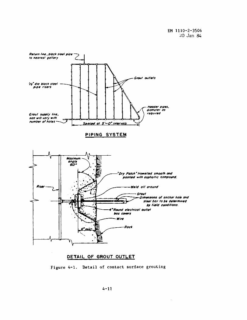
EM 1110-2-350620 Jan 84
Return Itne, block steel pipeto neorust gollery
Q-. A,
Gmt outlets
~t” dfo block S!Se!pipe risers
- ; :.a50&
Heoder pipes,
d!ometer os
Grout supply line, reoutred
size w)llrory w!thnumber of holes<
o t $-● interva
4
.
\
PIPING SYSTEM
>
-’IIIongle&kIlli60 ● ‘,Ill;
‘:,.*C11/.. 11
I
‘Qry patch ● ttowelled smooth md[l,
pointed with uspholtic compound.
‘;’;ti~~:::ofonc~~ho~~d
by field conditions.
“’i... ?“?=:’rico’mr’e’
Figure
‘~
DETAIL OF GROUT OUTLET
4-1. Detail of contact surface grouting
4-11
EM 1110-2-350620Jan 84
medium, and coarse silts; fine, medium, and coarse sands; and up to and in-cluding fine gravels. A method for determining the limits of groutability forthe coarser granular soils, i.e., medium sands through fine gravels, is de-scribed in paragraph 5-2e. Treatment of fine granular materials, i.e.,through coarse silts, is covered in EM 1110-2-3504. Methods of soil groutingare summarized as follows:
(1) Casing. A casing may be drilled, jetted, or pushed to the fulldepth to be treated and then withdrawn as grout is pumped into the soil. Theescape of grout up the contact surface of the casing and the soil may be aproblem. This method is used extensively in chemical grouting at shallowdepths.
(2) Grout sheath. In this method, a flush-joint grout pipe is groutedin, using a special brittle grout that prevents leakage up the outside of thepipe, The grout pipe is withdrawn a short distance, leaving a brittle groutsleeve below the pipe. Grout is pumped into the soil through cracks producedby the pressure of the grout in the brittle grout sleeve below the end of thegrout pipe.
(3) Pierced casing. A patented soil grouting method has been developedin which the casing is grouted in using a special grout. The casing can bepierced at any selected point by firing an explosive-impelled projectile froma device lowered into the casing.
(4) Tubes a manchette. In this method, a perforated pipe is groutedinto the hole with a special sleeve grout. The perforations are covered withshort sections of a rubber sleeve (manchettes) on the outside of the pipe thatact as one-way valves. Perforated sections of the pipe are placed oppositeinjection locations. A double packer is used to control the treatment loca-tion. The pressure on the grout pumped into the hole between the confiningpackers causes it to push past the small rubber sleeves covering the perfora-tions, rupture the sleeve grout, and enter the soil. This device is suitablefor injecting cement, clay, or chemical grout. The same holes and the samerubber-sleeved vents have been used in some instances for the injection ofeach of these grouts separately and in rotation into a soil. This permitseconomical treatment of soil containing large voids with an expensive chemicalgrout by first filling the large voids with less costly clay and cement grout.
(a) Clays and fine silts. Grouts in such ❑aterials can only displacethe grains by penetrating planes of weakness to form lenses or by compactingthe ❑aterials by forming grout bulbs. This type of grouting can be conductedusing cements or cements proportioned with other fine solids.
(b) Medium and coarse silts and fine sands. Granular material throughwhich water will ❑ove with relative ease will accept low viscosity chemicalgrouts to fill voids and form a more or less consolidated mass.
4-12
EM 1110-2-350620Jan U
(c) Coarse sands and gravels. High viscosity chemical grouts and highlyfluid cement slurries are usually found suitable for injection into suchmaterials.
(5) EM 1110-2-3504 provides detailed information relative to the in-fectivity limits that may be expected of various types of chemical and port-land cement grouts when they are injected into granular materials ranging fromnonplastic silt to fine gravel. The limits are also shown in figure 5-1.
i. Specialized Applications. Many specialized applications of groutingare currently in use. A discussion of some of these applications is presentedin Chapter 11. It is recommended that for specialized applications of grout-ing, or for any grouting using admixtures in the grout, laboratory tests beperformed on the grout and field test programs be considered. Chemical testsof groundwater or mixing water in areas of suspected mineralized water shouldalso be made, and the results should be used in the mix design.
4-6. Grouting Methods.
a. General Considerations. The best-known grouting methods are stagegrouting, stop grouting, series grouting, circuit grouting, and tremie orgravity grouting. In each method the split spacing procedure is followed todetermine final hole spacing. Holes for the initial or primary set aredrilled at the maximum spacing (10 to 40 feet) and grouted, and the spacing ofholes is reduced with each succeeding set until the criteria for completion ofgrouting are fulfilled. The holes for curtain grouting may be drilled oneither a single-line or a multiple-line arrangement (para 4-5). Usually thegrout curtain will be divided into horizontal reaches called sections. Thelength of the section is dependent on individual project characteristics, butmay be based on not including more than three or four primary holes. Drillingof grout holes should not be allowed in the same section where grouting isbeing done, and sometimes not in the adjacent section. The purpose of thisrestriction is to limit the number of open ungrouted holes that could acci-dentally be grouted by interconnection and to prevent the disturbance of un-cured grout by drilling fluids.
b. Stage Grouting.
(1) In the stage grouting method, progressively deeper zones are drilledand grouted in stages from the top of the grout hole. A stage of drilling iscompleted either when a predetermined depth of zone is reached or when a speci-fied condition is encountered. A single zone may include more than one stage.Primary holes in a given area are drilled to the first stage of depth, grout-ing is done at low pressure, and grout within the hole is subsequently removed
by jetting or other methods before it has sufficiently set to require redrill-ing. Similar stages of drilling and grouting are repeated as necessary toreach the bottom of the first zone.
4-13
EM 1110-2-350620 Jan ~
(2) After all first-zone grouting of primary holes in the section orarea has been completed and a minimum period of 24 hours has elapsed since thecompletion of grouting operations in any given hole, intermediate holes, lo-cated by the split spacing method, are drilled and grouted to the bottom ofthe first zone. Upon completion of all holes to the bottom of the first zoneand after a 24-hour period, the primary holes are drilled to the next stage ipthe second zone and grouted at higher pressures. The process of drilling, ‘washing, pressure testing, pressure washing, and grouting at progressivelyhigher pressures is continued until the ground is satisfactorily tight to therequired depth.
(3) The shallow zones of the grout curtain are initially grouted underlow pressure; however, during grouting of deeper zones under the stage grout-ing method, the shallow zone is subjected to progressively higher pressures.Theoretically, the zone can withstand the higher pressures because the voidsin the shallow zone should have been filled with grout during the low pressuregrouting of the shallow zone. Normally, there is little or no intrusion ofgrout into this zone under the higher pressures used for deeper zones and nofoundation lifting. There are exceptions, however, and the grout inspectormust be aware of the possibility and must be prepared to stop grouting imm-ediately to prevent heaving of the foundation.
(4) If any stage of a hole is found to be adequately tight as determinedby pressure testing, grouting of that stage may be omitted and the hole leftopen for drilling in the next lower stage.
c. Stop Grouting.
(1) Stop grouting, sometimes called “up-staging,” is a method wherebypackers or expansion plugs block off preselected portions of the holes whilethose portions are being grouted. The holes are drilled to their full depth,are pressure tested, and are grouted in successive stops or zones from the bot-tom up. (An exception to the requirement of drilling the hole to final depthis made when lost circulation or artesian conditions are encountered. Ineither of these cases, the hole is grouted prior to drilling to final depth.)Packers or expansion plugs are set in the holes at the top of the interval tobe grouted, blocking off the higher portions of the holes, and the intervalis pressure-tested and grouted. The lowest zone is grouted first. Thepackers are then raised to the top of the next higher stop, and grouting isrepeated. Grouting of holes of any one set (i.e., primary, secondary, etc.)should be completed for all zones in a particular section before drilling ofsplit-spaced holes for the next set is commenced. Grouting pressures areordinarily reduced with each higher stop because of less cover over the zonebeing grouted.
(2) Where grout communication from hole to hole is anticipated, a varia-tion of the stop grouting method may be employed utilizing a multiple packersystem. Experience has shown that holes grouted by transmission of grout from
4-14
EM 1110-2-350620 Jan ~
an adjacent hole or holes are only partially grouted, and therefore incomplete.The multiple packer procedure consists initially of the simultaneous use ofindividual packers in adjacent holes during pressure testing. The procedureinvolves testing at least two holes in advance of the hole to be grouted topredetermine the zones of possible grout take ahead of the grouting schedule.(Figure 4-2 shows examples of multiple packer settings under various condi-tions of water take.) The packers are left in each hole just above the lowesttake zone, and the hole is grouted under the maximum allowable pressure forthe zone. This allows the header to be shifted from hole to hole and thus in-creases the effectiveness of the job. This procedure reduces the costly re-quirement of redrilling and regrouping holes that have been grouted by trans-mission (interconnectionof holes). Knowledge of which adjacent holes acceptwater or grout is also helpful in determining the bottom hole depth for split-spaced holes.
d. Series Grouting. Series grouting is similar to stage grouting exceptthat each successively deeper zone is grouted by means of a newly drilled holeto eliminate the need for washing grout out of the hole before drilling deeper.Holes at regular intervals are drilled to the depth of the first zone and indi-vidually grouted from the top of rock at low pressure. The split-spacingmethod of reducing the grout hole interval is followed until the uppermostzone refuses grout at the permissible pressure. After the first zone has beencompleted, another series of holes is drilled into the second zone and groutedfrom the top of rock at higher pressures, following the same procedure as out-lined for the first zone. Additional series of holes may be drilled, depend-ing upon the final depth of grouting required. Maximum pressure is applied tothe deepest zone. The justification for using the higher pressures in thedeeper zones with this method is based upon the assumption that a blanket orbarrier, as provided by the previously grouted zones, prevents the escape ofgrout through, or the development of uplift in, the shallower zones. Some-times this does not occur and grout is intruded into the shallow rock underhigh pressure. If this occurs, the foundation may be lifted and grouting mustbe terminated or packers used.
e. Circuit Grouting. Circuit grouting requires the use of a double linegrouting system. The pump line is attached to a pipe that extends through anexpansion plug or packer or special header to within 5 feet of the bottom ofthe hole. Grout venting from this pipe fills the hole, flows through a secondopening in the expansion plug or header into the attached return line, and re-turns to the grout sump for recirculation. Thus, as soon as the pumping rateexceeds the rate at which grout is injected into the rock, the grout hole be-comes part of the grout circulation system. Circuit grouting may be used togrout a hole drilled to full depth as a one-time operation, or it may be usedas a modification of any of the other grouting methods described.
f. Gravity Grouting.
(1) Sometimes referred to as tremie grouting, gravity grouting is often
4-15
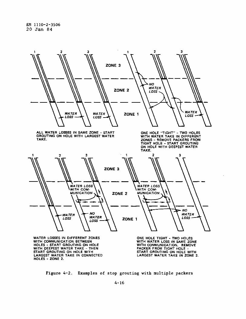
EM 1110-2-350620 Jan 84
1 2 3 1 2 3
ALL WATER LOSSES IN SAME ZONE -STARTGROUTING ON HOLE WITH LARGEST WATER
ONE HOLE “TIGHT” - TWO HOLESWITH WATER TAKE IN DIFFERENT
TAKE. ZONES - REMOVE PACKERS FROMTIGHT HOLE - START GROUTINGON HOLE WITH DEEPEST WATERTAKE.
1
——
WATER LOSSES IN DIFFERENT ZONES ONE HOLE TIGHT - TWO HOLESWITH COMMUNICATION BETWEEN WITH WATER LOSS IN SAME ZONEHOLES - START GROUTING ON HOLE WITH COMMUNICATION. REMOVEWITH DEEPEST WATER TAKE - THEN PACKER FROM TIGHT HOLE -START GROUTING ON HOLE WITH START GROUTING ON HOLE WITHLARGEST WATER TAKE IN CONNECTED LARGEST WATER TAKE IN ZONE 2.HOLES - ZONE 2.
Figure 4-2. Examples of stop grouting with multiple packers
4-16
EM 1110-2-350620 Jan 84
used in cases where large, open voids exist which will take grout freely. Ex-amples of this condition are found in soluble formations, basalt flows, andmine cavities. The gravity technique consists of drilling the hole to totaldepth, lowering a grout pipe to near the bottom of the hole, and pumping ingrout under near gravity pressure. When the pressure begins to build up, thegrout pipe is slowly raised and the grouting is continued. The procedure isrepeated until the hole is completely grouted. The grout pipe should be keptsubmerged in the grout at all times.
g“ Critique of Grouting Methods.
(1) Stage grouting.
(a) Advantages. All stage grouting, regardless of depth of zone, isdone from the top of the hole, usually through a short pipe or packer set inthe top of the hole. This method eliminates the need for deep packer settingsrequired for stop grouting. A smaller hole can sometimes be used for stagegrouting than that for stop grouting since no packer is involved. Stage grout-ing has a flexibility that permits special attention to be given to almost anylocal condition encountered, provided the specifications are written to permitpayment for the contractor’s efforts. Drill cuttings from lower zones cannotclog groutable openings in higher zones. The grouting of all zones is donethrough a single hole, making drilling costs much less than those for seriesgrouting, which requires a new hole for each cycle of drilling and grouting.Surface rock is subjected to increasing pressures and repeated application ofgrout from grouting of the deeper zones.
(b) Disadvantages. The principal disadvantage of stage grouting is thedanger of lifting or heaving the surface rock when grouting without a heavyconfining load. Heaving causes grout waste and may seriously damage the rockand/or any superjacent structure. Lifting occurs at comparatively low pres-sures when grout is actually injected into and displaces rock near the sur-face. Thinly bedded, horizontally stratified rocks and highly fractured rocksare easily lifted. A second major disadvantage of stage grouting, as comparedto stop grouting, is higher cost. A drill must be set up over each grout holeat least once for each zone in the hole, and grout lines must be connected tothe hole equally often. Both items add time and money costs to the job. Con-nections to grout holes are usually pay items, and more are required for stagegrouting. Labor is expended and grout is wasted for each stage of grout holethat is cleaned before deepening. Premature cleanout may result in flowbackof the grout injected into the rock, and this grout will also be wasted.
(2) Stop grouting.
(a) Advantages. This grouting method has several advantages: Imperfec-tions disclosed by drilling operations may be isolated by means of the expan-sion plug and given special treatment. Only one drill setup per hole is re-quired; pressure washing and testing may be concentrated in small segments of
4-17
EM 1110-2-350620 Jan 84
the holes by means of double expansion plugs, thereby improving the efficiencyof these operations; cleaning or drilling out holes after grouting is unneces-sary, less connections are required, and the method is ❑ore economical thanthe other methods.
(b) Disadvantages. Some disadvantages of stop grouting are: groutsometimes bypasses the grout stops, or expansion plugs, through vertical ornear vertical fractures or joints; a tight seal is difficult to obtain withexpansion plugs in fractured or broken rockhoneycombed rock;
, and in cavernous or solutionleaks into nearby holes may cause difficulties and may plug
fractures and seams and other imperfections in those holes above the zonebeing grouted; and sizes of holes that can be used for grouting are limited tothe sizes of packers or expansion plugs obtainable. Packers are frequentlylost due to their becoming grouted into the hole.
(3) Series grouting.
(a) Advantages. The advantages stated for stage grouting (except thelast listed) also apply to series grouting. Other advantages of series grout-ing are that all grouting is done from a new hole in freshly exposed rock, pro-viding maximum exposure of groutable voids, and grout injected into the rockis not lost by poorly timed cleanouts as in stage grouting.
(b) Disadvantages. The major disadvantages of stage grouting, which arethe danger of heaving and an increased expenditure of time and money, apply toseries grouting also. The increased amount of drilling makes series groutingthe most expensive of the methods described. There is a much greater dangerof heaving the surface rock with series grouting than in stage grouting.
(4) Circuit grouting.
(a) Advantages. Grout is kept alive in the entire hole until groutingis complete. Thus, small openings occurring below large ones can be groutedafter the large openings are filled. Caving holes can be grouted by jettingthe grout pipes through the caving zones. Holes can be flushed morethoroughly during the grouting operation in circuit grouting than by any othermethod. Caving or sloughing materials are removed from the hole by the risingcolumn of grout and later removed from the system by a screen placed betweenthe return line and sump.
(b) Disadvantages. If the packer is set near the top of the hole, theentire hole must be grouted at a sufficiently low pressure to prevent liftingof surface rock. If the packer is set several feet below the surface, theupper part of the rock is ungrouted. A larger hole must be provided to permitinstallation of the assembly. Excessive time is required to assemble anddisassemble grout pipe in the hole. In addition, the cost is higher than forstage or stop grouting.
4-18
EM 1110-2-350620 Jan 84
(5) Combining methods. No large grouting job is likely to be completedusing only one grouting method in the strictest sense of the definitions. Forexample, the drill water may be lost during the drilling of a hole for stopgrouting, and drilling must be stopped immediately and the hole grouted. Insuch cases it can be said that stop grouting is done by stages. In stagegrouting if the upper rock is so fractured that it cannot be sealed wellenough to withstand the higher pressures desired for the lower zones, it maybe necessary to grout the lower zones through a packer set below the fracturedrock. This is also a combinationof the stage and stop grouting methods. Insome cases circuit grouting may be used in fractured zones. A badly fracturedupper zone extended over a considerable area may require treatment by a gridof shallow holes grouted by the series or stage methods. The grid forms agrouted rock blanket before stop, stage, or series grouting is continued inthe lower zones of the area. Specifications should be flexible enough to per-mit the use of the method or methods best suited to whatever situation is en-countered and should provide a means of compensating the contractor for thework performed.
(6) Selection of method. Stage grouting and stop grouting are the twomost common methods of grouting. Service records show that effective resultscan be obtained by either method. If grouting is delaying another construc-tion operation and time is an important factor, stop grouting should be givenserious consideration. If higher pressures are needed in lower zones of thegrout hole than near the top, stop groutirigis the best suited method. Ex-amples of the latter are reservoir rims, dam abutments, mine shafts or othersimilar deep excavations, and underground structures grouted from the surface.Portions of grout holes must occasionally be drilled through rock above thehorizons requiring treatment. Since grouting the upper rock is unnecessary,stop grouting is well adapted to this situation. If sufficient rock overliesthe grouting horizon, the entire hole may be grouted with one stop and withonly low or gravity pressure at the collar of the hole. If the surface rockin the grouting area is thinly bedded and has a nearly horizontal attitude,stop grouting is the best method to avoid lifting. A stage of grouting isusually required if the drill water is lost before the hole reaches finaldepth. Stage grouting should be used to prevent natural muds formed by drillcuttings from shales or similar rocks from filling or obstructing groutableopenings at higher horizons. Consolidation of the upper rock may be desirableor necessary before any grouting at depth proceeds, and will necessitate thestage or series grouting method. If grouting the foundation of an existingstructure is desired at pressures comparable to the load imposed by the struc-ture, great care must be exercised to avoid heaving and tilting the structure.The danger of heaving is less if the rock is massive or medium bedded, thejoints are at high angles, or the strata are steeply dipping.
4-7. Foundation Drainage.
a. Galleries are generally provided in concrete dams for drilling,
4-19

EM 1110-2-350620 Jan 84
grouting, and drainage. Where possible, the minimum size of the galleryshould be 8 by 8 feet.
b. In addition to grouting, drainage may be required to control seepageand pressures in foundations or abutments. Foundation drainage features,filters, and other measures act together, or in combination with the groutcurtain (if present), to control seepage, reduce pressures, and prevent piping.Foundation drainage features include drilled drains, relief wells, drainageadits, drainage galleries, and pervious drains or filters.
c. Galleries have not been constructed in embankment dams built by theCorps of Engineers but may be considered for future projects.
d. Drainage is one of the most effective means of seepage control.Drains should not be drilled until after grouting has been completed. Whengrouting is necessary near existing drainage features, caution is necessary toavoid grouting the drains or wells. Effectiveness of the drainage featuresshould be checked after the grouting program, and the drains or wells shouldbe cleaned and/or rehabilitated and new drains or wells provided as necessary.
e. Foundation drains in galleries are frequently inclined downstream toincrease the distance between the drains and the grout holes. Drain holesshould be a minimum of 3 inches in diameter and may or may not be lined withslotted polyvinyl chloride or metal casing, depending on the geologic condi-tions and groundwater. Gravel or sand should never be used to fill the hole.
f. Drains in tunnels and abutments may be horizontal or inclined at anyangle. If drains are horizontal or inclined upward in shale or other sensi-tive materials, they should be provided with traps at the collar to preventair circulation in the hole and should be cased if necessary.
g. Drains should be designed so that they are accessible and can be peri-odically inspected and cleaned.
4-20
CHAPTER 5GROUT MATERIALS
5-1. Grout Materials.
a. Introduction. The user of portland cement grout must consider twomajor factors: (1) the compatibility of the individual materials and (2) theintended purpose of each of the constituents. The results of adding variousmaterials to the grout mixture will enable the user not only to develop a widerange of physical properties in the grout but also to make adjustments in thefield to meet changes in project conditions.
b. Portland Cements. The most common and best known hydraulic cementsused worldwide as the basic ingredient for cement grouts are portland cements.Some of the cements listed below may not be economically available in all sec-tions of the country. The availability of portland cement should be deter-mined before the type is specified. Types of portland cement produced, andthose which may be considered for use in grouting applications, are as follows:
(1) Type I portland cement. Type I is accepted as the general purposecement for use in the vast majority of grouting applications when specialproperties of other types are not required.
—.
(2) Type II portland cement. Type II is manufactured to resist moderatesulphate attack and to generate a slower rate of heat of hydration than thatexhibited by Type 1. ~.
(3) Type III portland cement. Type III is used when high early strengthsare desired, usually 2 weeks or less. It is considered for use in emergencyrepairs in instances that require grouting application or phases of groutingapplications to be put into service quickly. Since particle size-is smallerthan in other types, it is sometimes specified for grouting fine cracks.
(4) Type IV portland cement. Type IV generates less heat during hydra-tion than Type II cement. It develops strength at a much slower rate thanType I. It is considered for use in large mass grout placements when hightemperatures of heat of hydration are objectionable.
(5) Type V portland cement. Type V is manufactured for use in groutexposed to severe sulphate action. It is used principally when a high sul-phate content is present in soils or groundwaters.
(6) Air-entraining portland cement, Types IA, 11A, and 111A. Thesetypes correspond in composition to Types I, II, and III, respectively. Thesecements contain small quantities of air-entraining materials that are incorpo-rated by intergrinding them with the clinker during manufacture. They arerarely used in grouts and are only considered if a grout may be exposed tosevere freezing and thawing conditions.
5-1
EM 1110-2-350620 Jan 84
(7) Oil well cements. Cements manufactured for use in wells are subjectto wide ranges of temperature and pressure and consequently differ from theASTM types that are manufactured for use in a less harsh environment. In meet-ing well requirements the American Petroleum Institute (API) provides specifi-cations covering eight classes of oil-well cements, designated Classes A, B,C, D, E, F, G, and H. The API Classes A, B, and C correspond to ASTM Types I,II, and III. There are no corresponding API Classes for ASTM Types IV and V.
c. Pozzolans. These materials are siliceous or siliceous and aluminousthat in finely divided forms and in the presence of water chemically reactwith calcium hydroxide of portland cements to form compounds embodying ce-mentitious properties. Pozzolans may be divided into three classes.
(1) Class N. This class includes raw or calcined natural pozzolans,such as certain diatomaceous earths; opaline cherts and shales; tuffs andvolcanic ashes, such as pumicites, which may or may not be processed by cal-cination; and some clays and shales that require calcination to induce satis-factory properties.
(2) Class F and Class C. These are fly ashes that are finely dividedresidues resulting from combustion processes of ground or powdered coal. Flyash is the most commonly used pozzolan for grouts.
d. Admixtures. Any material other than water, fine aggregate, and hy-draulic cement added to the grout immediately before or during its mixing toalter its chemical or physical properties to a desired characteristic duringits fluid or plastic state is classified as an admixture. The principal mate-rials used for these purposes are as follows:
(1) Accelerators. The most widely used accelerator in grout mixtures iscalcium chloride (CaC12). Generally, calcium chloride can be safely used inamounts up to two percent by weight of the cement. It is mainly used whenearly stiffening and setting of grout mixtures are desired. Use of calciumchloride in instances where grout may be exposed to cold weather is effectivein minimizing the possibility of grout freezing during setting. This accelera-tor may aggrava~ sulphate attack, alkali-silica reaction, and in high concen-trations, it acts as a retarder. It should not be used when the grout is incontact with steel. Other accelerators include certain soluble carbonates,silicates, and triethanolamine. Granular and flaked calcium chloride can besuccessfully used if added to the grout by being dissolved in a portion of themix water.
(2) Retarders. The most commonly used retarders are organic chemicals,most likely lignosulfanic acid salts or hydroxylated carboxylic acid salts ormodifications of these additives. Retarders are used to offset the unde-sirable accelerating effects of high placement temperatures and to prolonggrout injection or placement time. A retarder may be required for tempera-tures above 70 degrees Fahrenheit.
5-2
(3) Water reducers. The kinds of materials used for retarders are essen-tially the same components for water reducers. They increase the pumpabilityof grout mixtures by increasing their fluidity and increase their strengths byreducing the water content of the mixtures while at the same time maintainingthe same degree of fluidity. Water reduction also decreases the permeabilityand porosity of portland cement grout mixtures.
(4) Aluminum powder. Aluminum powder is sometimes used in portland ce-ment grouts to produce shrinkage compensation or a slight to moderate amountof controlled expansion during the plastic state of the grout. This expansionis a result of the reaction of the alkalies of the cement with the aluminum,which produces a small amount of hydrogen gas in the grout. The amount andrate of the expansion is largely dependent on the temperature of the grout, thealkali content of the cement, and the type, fineness, and particle shape of thealuminum powder used. Unpolished, nonleafing powders of high purity and lowgrease have been found to be satisfactory in portland cement grouts. The ex-pansion occurs during the fluid state of the grout and is completed prior tofinal setting of the grout. Two or three grams, or about 1 teaspoonful, ofthe powder per sack of cement is generally used. Laboratory or field trialmixtures are essential prior to the use of aluminum powder in project work.
(5) Fluidifiers. Fluidifiers in grout mixtures inhibit early stiffening,hold fine particles in suspension, and produce a controlled amount of expan-sion prior to initial setting. The composition of the fluidifier may includeseveral constituents to produce the stipulated properties. The principal in-gredients are usually a gas-generating additive, a retarder, and a dispersingagent. Pumpability of portlandcement grout mixtures is improved by the addi-tion of small to moderate amounts of finely ground fly ash, rock flour, pumic-ites, diatomites, and bentonites. These admixtures, with the exception ofmost fly ashes, will usually require an increase in mixture water. Trial mix-tures should be tested for desired performance characteristics prior to usingthose materials in field work.
e. Fillers. Sometimes referred to as extenders, fillers are varioustypes of materials used in grout mixtures to replace various amounts of ce-ment, mainly for reasons of economy when substantial quantities of grout arerequired to fill large voids, trenches, and cavities, and to stem bore holes,shafts, and tunnels.
(1) Filler use. Caution should be exercised in the use of fillers asthey tend to increase the setting time of grouts, and in the case of highwater content grouts, may result in a high degree of shrinkage and strengthloss. Silts and clays require careful selection as they may contain excessiveamounts of organic ❑aterials. Accelerators and water-reducing admixturesshould be considered when fillers are used.
(2) Fine mineral fillers. Rock flour, clay, fly ash, silt, diatomite,pumice, barite, and others are fine mineral fillers.
5-3
EM 1110-2-35062U Jan 84
(3) Coarse fillers. Ordinary sand is the most common of all coarsegrout fillers and is usually screened to a desired gradation. Two parts ofsand to one part of cement by weight is the practical upper limit of sand con-tent in a grout mixture unless mineral fillers or admixtures are used. Othercoarse fillers where strength is not a consideration include shredded rubber,perlite, wood shavings and chips, shredded and chopped cellophane, crushedcottonseed hulls, mica flakes, steel, nylon and plastic fibers, plastic andpolystyrene beads, and others.
(4) Mineral fillers. Care is required in the selection of mineralfillers as materials for permanent work. The fillers generally used are sand,rock flour, and fly ash; the latter has become more commonly used in recentyears. Trial batches should be conducted when fillers are introduced in port-land cement mixtures.
(5) Fly ash. Fly ash may be used both as a filler and an admixture, andin both instances it will produce cementitious properties in the grout mixturewhen the finely divided siliceous residue reacts chemically with the portlandcement. The maximum amount of fly ash should not exceed 30 percent of thecement by weight as a replacement material of the cement if strength levelsmaintained at approximately the 28-day age are desired.
(6) Diatomite. Diatomite is made up of fossils of minute marine or-ganisms and is composed principally of silica. The fineness of processeddiatomite may range from three to 15 times finer than that of cement. It re-sembles fine powder in texture and appearance. Small amounts improve pump-ability in grouts; however, in large amounts as a filler material, a very highwater-cement,ratio will be required and it can be used only to fulfill jobrequirements for low-strength grouts.
(7) Pumicite. Pumicite is a processed material produced from the pul-verizing of volcanic ash, ashstone, tuff, or pumice. Pumicite serves not onlyas a filler, but in small amounts, it also promotes pumpability. Pumicitealso produces pozzolanic cementitious properties in the mixture. The mixturewater demand is higher than that of fly ash but not nearly as high as that re-quired by diatomite.
(8) Bentonite. Bentonite is a montmorillonite sodium base clay oftencalled gel, and has grown in use in recent years to improve the pumpability ingrouts. Advantages of using bentonite also include its tendency to reduceshrinkage and to prevent bleeding. Bentonite may also be used as a filler;however, the mixture water demand, like that of diatomite, increases consider-ably. Strength reductions are consequently quite high. Mixtures using ben-tonite prehydrated prior to being mixed in the grout require approximately75 percent less bentonite than those using bentonite introduced as a dryingredient.
5-4
EM 1110-2-350620 Jan 84
(9) Barite. A naturally occurring barium sulphate (BaS04), barite hasa specific gravity of approximately 4.5. Processed barite resembles bentonitein physical characteristics. Barite has an extremely high water demand whichresults in low strength development in grouts. Barite can serve as a fillerin small to moderate amounts when high density grouts are desirable and lowstrengths are acceptable.
f. Mixing Water. Water acceptable for drinking is generally acceptedfor use as the mixture water for grouts. The suspected presence of objection-able impurities, especially those in large concentrations, should be investi-gated. These impurities include dissolved sodium or potassium salts, alkalies,organic matter, mineral acids, sugars or sugar derivatives, and silts. Waterobtained from natural sources “onsite” must be tested (CRD-C 400) and approved.
5-2. Portland Cement Grout Mixtures.
a. Proportioning.
(1) The water-cement ratio in grouting mixtures should be carefullyconsidered. The ratio not only influences strength and workability but alsoaffects pumpability, viscosity, penetration, grout take, setting time, andpumping pressures. A high water-cement ratio may also adversely affect thelong-time durability of grouts used in various permanent types of groutingapplications.
(2) The volume basis is comonly used in the field for the sake of con-venience in that it eliminates batch weighings when precision weighing ofconstituents is not essential. Mixtures used in the field are frequently ex-pressed as the ratio of the volume of water in cubic feet to one sack ofcement having a “loose” volume of one cubic foot. The mixtures may range from6:1 to 0.6:1 for much field work. Mixtures as thin as 10:1 are sometimes em-ployed in rare cases; however, such admixtures as accelerators, retarders,fluidifiers, and water reducers may be required to modify these mixtures tomeet certain job conditions. The volume of fluid grout actually produced byany combination of properly proportioned materials is equal to the sum of theabsolute volume of cement plus absolute volume of filler material or signifi-cant amounts of admixtures plus volume of water. The absolute volume of one94-pound sack of cement (using an average specific gravity of 3.15 for port-land cement) is 0.478 cubic feet. Usually only approximations are necessaryand one sack of cement can be assumed to yield 0.5 cubic foot.
b. Neat Slurries. Mixtures with a high degree of fluidity, whichusually contain no sand and only cement and water and small amounts of modi-fiers that do not appreciably alter the fluidity characteristics of the mix-tures, are referred to as slurries. Such mixtures have a very low viscosityand sometimes are referred to as self-leveling, thin, or highly fluid.
c. Foamed Slurries. Sometimes referred to as cellular grout, foamed
5-5
EM 1110-2-350620 Jan 84
slurries are used in special applications, such as backpacking, for buriedhardened structures that will or might be subjected to impact or dynamic load-ing. This slurry is also used to protect monitoring instrumentation fromshock blast when it is used in tests associated with nuclear or high-explosivetesting and as a backfill material as well as a material that can be developedto control rates and amounts of permeability when such permeability is desired.This grout is also used in temporary construction because of its ease ofexcavation.
(1) Mixture. The slurry is composed of a water-portland cement mixtureto which a proprietary foam is added in various amounts to obtain a range ofstrength and density levels that will result in low stresses and high strains.The foam is provided in liquid form and is transformed using a foam generator.One manufacturer of a foaming product describes his product as a hydrolyzed,neutralized, stabilized protein foaming agent.
(2) Physical properties. Compressive strengths may range from 50 to1000 pounds per square inch and densities from 40 to 80 pounds per cubic foot.Type I or II cement is normally used in the neat phase of the slurry. Thewater-cement ratios normally range from 0.5 to 0.6 by weight.
d. Sanded Grouts. Sand in grouts is used mainly as a filler for reasonsof economy. Other benefits include lower water-cement ratios, less heat ofhydration, and less shrinkage. The higher the degree of sphericity of thesand, the better the pumpability becomes. Pumpability also increases with thefineness of the sand; however, a higher water content is required. Processedand bank run sands are usually screened over a No. 16 screen; however, theymay frequently be used “as is.” Natural or manufactured sand may also be used.A series of investigations was conducted by the U. S. Army Engineer WaterwaysExperiment Station (wES) covering the testing of sanded grouts. Physical char-acteristics of sanded grouts determined from these investigations are sum-marized in Appendix D. The investigations have indicated the following:
(1) Two parts of sand to one part of cement canbe pumped without theaid of admixtures at normal temperatures.
(2) Small amounts of diatomite appreciably increase the sand-carryingcapacity of grouts. Bentonite contents in excess of 10 percent by weight ofcement permit enormous amounts of sand in mixtures but result in very littlestrength development due to their extremely high water demand.
(3) Sand deficient in material passing the No. 100 sieve requires the,addition of finely divided mineral admixtures to increase the sand-carryingcapacity of the grout. Sand containing as much as 25 percent of fines passingthe No. 100 sieve can be successfully pumped at one to three ratios of cementto sand by volume or weight.
5-6
EM 1110-2-350620 Jan 84
(4) The addition of fine materials requires increases in water contentswhen a given degree of fluidity is desired.
(5) Sands manufactured from limestone and traprock can be successfullypumped.
(6) Limestone fines were more efficient pound for pound in promotingpumpability than was fly ash or loess.
(7) men 1.5 parts of fly ash and 1.0 part of diatomite were proportionedto one part of cement by weight in mixtures containing crushed limestone having10 percent fines passing the No. 100 sieve, 7.5 and 12.0 parts of sand could bepumped, respectively. High water contents and low strengths are also revealed.
(8) The quality of portland cement grout proportioned with 25 percentfly ash by weight of cement did not appear to be lower than similar grout with-out fly ash.
e. Groutabilitv Ratio. Groutabilitv ratio is an indication of the in-jectability of solid suspension grouts in~o granular materials. The “D” sizeis the designation given-to the percentage-p~ssing sieve size of a cement,sand, or gravel. A grout having 85 percent passing the No. 200 sieve is said
‘0 ‘ave a ’85of 74 microns, the sieve opening; and a sand having 15 percent
passing the No.16 ‘ieve ‘as a ’15
size of 1,190 microns. The Groutability
Ratio N is derived from these values and is expressed as D15/D85, which in
this instance results in 1,190/74 = 16. Caution should be exercised in ‘select-ing N. The N = D15/D85 ratio may be satisfactory in the above case where
N = 16. Groutability becomes questionable as N approaches 6, which is thevalue where filtering begins. N generally should be greater than 25 but insome cases may be as low as 15, depending upon physical properties of thegrout materials. Figure 5-1 gives a graphic interpretation of this equation.It shows (1) typical grain-size curves for portland cement, Boston blue clay,ordinary asphalt emulsion, and special Shellperm asphalt emulsion, and (2) thelower limits (D15) of sand groutable by the above-described grout materials.
f. Fluid Physical Properties. Fluidity is the major indication of thedegree of pumpability or nonpumpability that a grout will exhibit. In addi-tion to stiff-and thin, fluidity is expressed in the three follow~ng terms.High fluidity is a fluid mixture of the “self-leveling” type, is highly flow-able, often referred to as very thin, and is very low in viscosity. Moderatefluidity is a flowable mixture that is described as being within the limits offlowability having a moderate degree of viscosity. Minimum fluidity is astiff mixture classified as being in the plastic range, exhibiting a fewinches of slump, and described at times as being nonflowable or thick. Mea-surements of fluidity include grouts having time-of-efflux ranging between 10
5-7
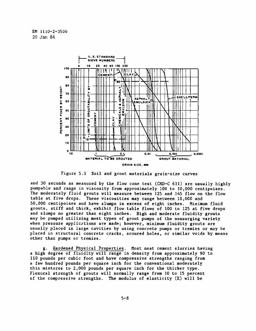
EM 1110-2-3506
20 Jan 84
I 00
90
aw 50zcb 40zwu 30K
:20
0
t-
U.S.STANDARDSIEVE NUMBERS
14 10 20 40 60 100 200
10 1 0.> 0.01
MATE2E GROUTED GROUT MATERIAL
GRAIN SIZE. MM
Figure 5.1 Soil and grout materials grain-size curves
and 30 seconds as measured by the flow cone test (CRD-C 611) are usually highlypumpable and range in viscosity from approximately 100 to 10,000 centipoises.The moderately fluid grouts will measure between 125 and 145 flow on the flowtable at five drops. These viscosities may range between 10,000 and50,000 centipoises and have slumps in excess of eight inches. Minimum fluidgrouts, stiff and thick, exhibit flow table flows of 100 to 125 at five dropsand slumps no greater than eight inches. High and moderate fluidity grouts❑ay be pumped utilizing most types of grout pumps of the nonsurging varietywhen pressure applic:~tionsare ❑ade; however, ❑inimum fluidity grouts areusually placed in large cavities by using concrete pumps or tremies or may beplaced in structural concrete cracks, scoured holes, or similar voids by meansother than pumps or tremies.
g“ Hardened Physical Properties. Host neat cement slurries havinga high degree of fluidity will range in density from approximately 90 to110 pounds per cubic foot and have-compressive-strengths ranging froma few hundred pounds per square inch for the conventional moderatelythin mixtures to 2,000 pounds per square inch for the thicker type.Flexural strength of grouts will normally range from 10 to 15 percentof the compressive strengths. The modulus of elasticity (E) will be
5-8
EM 1110-2-350620 Jan 84
approximately half of that exhibited for concrete of the same level ofstrength. The moderately fluid grouts usually have densities in the range of110 to 125 pounds per cubic foot and compressive strengths between 2,000 and3,000 pounds per square inch, and the minimum fluidity types willhave densi-ties ranging from 125 to 140 pounds per cubic foot and compressive strengthsbetween 3,000 and 6,000 pounds per square inch. In critical areas, such asfor ❑achine bases, laboratory strength tests may be conducted to determinesuitable mixes. Shrinkage, permeability (CRD-C 48), and creep tests may alsobe desirable.
5-3. Special Cements and Mixtures.
a. Expansive Cements. Expansive cements have become commercially avail-able in recent years principally for use in compensating for normal shrinkageoccurring during the first few weeks of curing and hardening of grouts. Thesetypes of expanding cements are not to be confused with the expansion obtainedby hydrogen, oxygen, or nitrogen gas liberation that occurs in grouts onlyduring the fluid phase. A chemical compound present in expansive cement is ananhydrous calcium sulfoaluminate, which in the presence of lime, calcium sul-fate, and water, hydrates to form ettringite and to produce the expansion.The bar method restrained expansion tests (American Society for Testing andMaterials (ASTM) C 878) of the cements will range from approximately 0.04 to0.10 percent. Grout mixtures containing these cements may be used undermachine bases or column bases, for bolt anchorage, in concrete cracks, behindtunnel and shaft liners, for borehole and tunnel stemming, and in similar ap-plications where drying shrinkage does not occur to a significant degree.These cements do exhibit early stiffening characteristics; consequently, re-tarding and water-reducing admixtures should be considered.
b. Gypsum Cements. Gypsum cements are generally quick setting, are com-monly used for pothole and chuckhole quick repair, and are sometimes selectedfor use in rock and anchor bolting. Because of their quick setting properties,gypsum cements are sometimes used when temperatures are near freezing. Aslight amount of expansion is normal in these t~es of cements. Caution ❑ustbe exercised in their use as durability is questionable when they are exposedto aggressive environments (i.e., freezing, salts, high temperatures, wettingand drying). Gypsum cements are available in a wide range of setting timesand strengths. Their behavior is quite variable from one brand to another.Gypsum cement is sometimes used as an admixture to accelerate the set of port-land cements as well as in small quantities to overcome false set problemsthat may occur in portland cements. Gypsum cements should be evaluated in thelaboratory before they are used, especially if the application will require adegree of permanence. They should not be used for permanent grout curtains indams.
tingsuch
c. Quick-Setting Cements. Cements that reveal an initial and final set-time of approximately one-half that exhibited by normally setting cements,as Type I or Type II, are considered quick setting. Gypsum, Type III,
5-9
EM 1110-2-350620 Jan 84
high alumina, and regulated-set cements, the latter containing haloaluminate,are the most commonly used when quick setting is required. High temperatureenvironments will further accelerate the setting time of these quick sets to apoint that may approach flash setting. Quick-set cements should be laboratoryand field tested prior to use.
d. Fluid and Hardened Properties. Expansive cement, gypsum, and quick-setting cements require somewhat higher water contents than other types as aresult of initial hydration, causing early stiffening. All must be batchedand placed quickly to avoid setting up in mixers, pumps, lines, or buckets.Generally, the mixtures are initially self-leveling; however, within secondsor ❑inutes, they begin to stiffen and set. Some gypsum cements will developcompressive strengths ranging up to 10,000 pounds per square inch in a ❑atterof a few days. Type III cement grouts normally develop in 7 to 10 days agestrengths that Types I, II, IV, and V develop in 28 days age. High aluminaand regulated-set cements behave somewhat like Type III; however, they aresomewhat quicker setting and higher in ultimate strength development.
5-4. Mixture Adjustments.
a. As noted in paragraph 5-2a the volume of fluid grout produced by anycombination of properly proportioned materials is equal to the sum of the ab-solute volume of the cement plus the absolute volume of filler material orsignificant amounts of admixtures plus the volume of water. The absolutevolume of loose ❑aterial (e.g. cement, fly ash, diatomite, bentonite, andsand) is always computed from weight and specific gravity:
Absolute Volume =
and volume of liquids is
Volume =
weight of loose materialspecific gravity x unit weight of water
computed:
weight of liquid.. .. . .. ..unlr.welgnc or Llqula
b. When it is desirable to maintain a given yield for a grout batch, orto increase or decrease the amount of water or loose materials, the precedingcomputations ❑ust be made in making such adjustments whether such adjustmentsare made for improving pumpability, for increasing or decreasing strength ofgrout mixtures, or for possible adjustment of density or other desired physi-cal properties. Strength ❑ay not be a controlling factor, as in much subsur-face water control grouting, and thiming and thickening of the basic mixturemay therefore be required to obtain the desired grout take at any given loca-tion of a downhole injection.
c. Figures 5-2, 5-3, and 5-4 are charts including portland cement con-tent of mixtures, and portland cement thickening and thinning, respectively.For either thiming or thickening, the cement content of a given volume of
5-1o
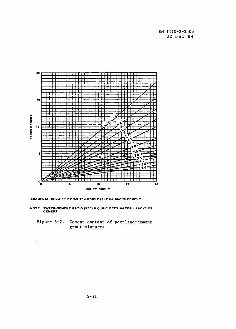
EM 1110-2-350620 Jan 84
“o 5 10 1s 20
CU FT GROUT
EXAMPLE: 10 CU FT OF 2.0 W/C GROUT (A) =4.0 SACKS CEMENT.
NOTE: WATER-CEMENT RATIO [W/Cl = CUBIC FEET WATER + SACKS OFCEMENT.
Figure 5-2. Cement contentgrout mixtures
of portland-cement
5-11
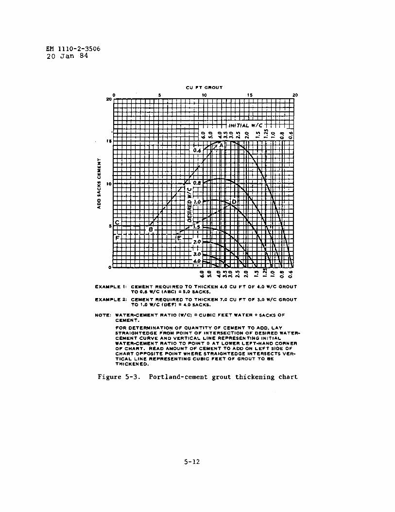
EM 1110-2-350620 Jan 84
Ex
Ex
CU FT GROUT
o 5 1020
$5 20
15
10
s
o
AMPLE 1: CEMENT REQUIRED TO THICKEN 4.0 CU FT OF 4.0 W/C GROUTTO 0.6 W/C (ABC) = 5.0 SACKS.
AMPLE 2: CEMENT REQUIRED TO THICKEN 7.0 CU FT OF 3.0 WIC GROUT
NOTE:
TO 1.0 WjC (DEF) = 4.0 SACKS.
WATER-CEMENT RATIO (W/C) = CUBIC FEET WATER + SACKS OFCEMENT.
FOR DETERMINATION OF QUANTITY OF CEMENT TO AOD. LAYSTRAIGHTEDGE FROM POINT OF INTERSECTION OF DE51RE0 WATER-CEMENT CURVE ANO VERTICAL LINE REPRESENTING INITIALWATER-CEMENT RATIO TO POINT O AT LOWER LEFT-HAND CORNEROF CHART. READ AMOUNT OF CEMENT TO AOD ON LEFT SIOE OFCHART OPPOSITE POINT WHERE STRAIGHTEDGE INTERSECTS VER-TICAL LINE REPRESENTING CUBIC FEET OF GROUT TO BETHICKENED.
Figure 5-3. Portland-cement grout thickening chart
5-12
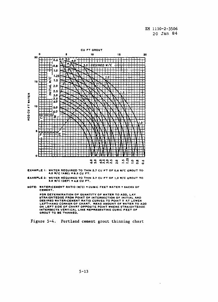
EM 1110-2-350620 Jan 84
CU FT GROUT
o 5 10 1s 20.20
!s
to I 1 1 , I1 I I II~6.0~ !>!=!?.!~.,
I I
s
o0.0 O.qoq o mxoaeWmvmmm&L-. -00
EXAMPLE 1: WATER REQUIRED TO THIN 2.7 CU FT OF 0.6 w/C GROUT TO4.0 w/c (ABC) = 8.3 CU FT.
EXAMPLE 2: WATER REQUIRED TO THIN 3.7 CU FT OF 1.0 W/C GROUT TO
NOTE:
3.0 w/c (DEF) = 4.9 cu FT.
WATER-CEMENT RATIO (W/C) =CUBIC FEET WATER + SACKS OFCEMENT.
FOR DETERMINATION OF QUANTITY OF WATER TO AOD, LAYSTRAIGHTEDGE FROM POINT OF INTERSECTION OF INITIAL ANDOESIRED WATER-CEMENT RATIO CURVES TO POINT O AT LOWERLEFT-HAND CORNER OF CHART. READ AMOUNT OF WATER TO ADDON LEFT SIDE OF CHART OPPOSITE POINT WHERE STRAIGHTEDGEINTERSECTS VERTICAL LINE REPRESENTING CUBIC FEET OFGROUT TO BE THINNED.
Figure 5-4. Portland cement grout thiming chart
5-13
EM 1110-2-350620 Jan 84
grout is first determined. The cubic feet of grout is divided by the cubicfeet of grout obtained from a one-sack batch, based on the absolute volume ofa sack of cement being approximately 0.5 cubic foot.
EXAMPLE: Find the number of sacks of cement in a 12.6-cubic-footbatchof 4:1 grout and in a 12.6-cubic-foot batch of 0.75:1 grout.
For 4:1 mixture
4 (cubic feet of water) + 0.5 (solid volume of 1 sack of cement)= 4.5 cubic feet. 12.6 + 4.5 = 2.8 sacks of cement
For 0.75:1 mixture
0.75 (cubic foot of water) + 0.5 (solid volume of 1 sack of cement)= 1.25 cubic feet. 12.6 + 1.25 = 10.1 sacks of cement
d. The measured thinning of a grout requires the addition of cubic feetof water equal in number to the number of sacks of cement in the grout to bethinned multiplied by the difference between the figures representing thewater in the water-cement ratios for the grout on hand and the mixture desired.
EWPLE : Determine cubic feet of water necessary to thin 7.2 cubic feetof 1:1 grout to 3:1 grout.
There are 4.8 sacks of cement in 7.2 cubic feet of 1:1 grout(7.2 + 1.5 = 4.8).
The difference between the figures representing the water in thewater-cement ratios of the two mixtures (3:1 and 1:1) is 2. Theamount of water needed to bring 7.2 cubic feet of a 1:1 mixture to a3:1 mixture is 9.6 (2 x 4.8 = 9.6).
e. The measured thickening of a grout is accomplished by subtracting theabsolute vclume of the sacks of cement in cubic feet from the cubic feet ofgrout to obtain the volume of water in the grout. Cement is then added togive the desired water-cement ratio with this volume of water. The adjustmentshould be made to the nearest whole sack so as to simplify batching operations.The following is an example of thickening:
Thicken a 5.6-cubic-foot mixture to a 1:1 mixture.
Mixture contains 4.8 cubic feet of water and 1.6 sacks of cement. Re-quired are 4.8 cubic feet of water and 4.8 sacks of cement for producinga 1:1 ratio. The addition of 3.2 sacks could be made; however, to avoidfractions of sacks of cement during batching, add 0.8 cubic foot of waterand 4.0 sacks of cement.
5-5. Chemical Grouts. ..
a. General Statement. Chemical grout provides the construction
5-14
EM 1110-2-350620 Jan 84
industry with a variety of benefits that are a result of improved gel-timinginjection control and extended infectivity limits as well as increases in thestrength development of various systems. Chemical grouts may be defined astrue solutions composed of two or more chemicals that react to foti soft,flexible gels, and semirigid and hard rigid gels.
b. Application Areas. Most chemical grout systems (e.g., acrylamides,silicates, and lignins) are used to increase the mass strength of soils and insubsurface water control. The great majority of applications are associatedwith foundation work. Epoxy and polyester resins are used not only in shallowcrack repairs in concrete and rock but also for the emplacement of rock boltsand anchors. Water-base resins, somewhat higher in viscosity than acrylamideand silicate types but much lower than the viscosities common in portlandcement grout, may be considered for grouting medium sands and coarse silts.Caution should be exercised in the use of chemical grouts since various sys-tems have toxic and caustic constituents. Environmental restrictions mayeliminate the use of certain chemicals for many grouting applications.
c. Self-Contained Systems. Self-contained two-component systems thatcould be classified as chemical grouts have recently become available. Thesesystems are designed primarily for the anchoring of tendons, rebars, androckbolts.
d. Reference. Engineer Manual EM 1110-2-3504 should be used as a guidewhen the use of chemical grouts is being considered. The manufacturer ofthose systems that appear to meet job requirements should be contacted forverification. Consideration should be given to conducting laboratory andfield evaluations of the system or systems being considered as likely candi-dates for a given application.
5-6. Asphalt Grouts. Asphalt grouts have occasionally been used in success-fully sealing moderate to large subsurface water flows in rock channels wherecement grouts failed, or where the use of cement grout was not consideredpractical because of the configuration of the area to be grouted and the vol-ume and velocity of the water flow. Hot asphalts and asphalt emulsions havebeen used to form barriers to water flow. Hot asphalts are generally heatedto approximately 400° F when used for grouting. Care should be exercised inmaintaining the heating temperature of a hot asphalt system below its reportedflash point. Asphalt emulsions, immiscible in water, are applied cold and aresuspended in water in colloidal form. Special chemicals are added to the mix-ture to cause “breaking,” which brings about flocculation and subsequent co-agulation in forming an effective grout. The control of coagulation time isan important factor to ensure that the proper amount of coagulation occurs atthe proper time at the desired subsurface location.
5-7. Clay Grouts. Fine clays are useful as fillers in lean portland cementgrouts. Benefits derived from their use include improved pumpability, in-fectivity, and economy. The two principal types of clays employed in grouting
5-15
EM 1110-2-350620 Jan 84
work are montmorillonite and kaolin. Attapulgite is a third type that is usedin salt domes and in seawater grouting or other areas of application wheremoderate to high saline conditions are present. Bentonite is used in groutmainly because of its gel swelling properties, which are not exhibited bykaolin.
5-16

EQUIPMENTCHAPTER 6
EM 1110-2-350620 Jan 84
6-1. Introduction. Guidance for selecting or approving the specializedequipment necessary for a grouting project is provided below, and operationalprinciples for the equipment are outlined and related to job requirements.Additional guidance for selection of drilling methods is contained inparagraph 4-4.
6-2. Drilling and Grouting Equipment.
a. Drill Rigs. In the selection of a drill, site considerations and jobdrilling/grouting requirements dictate the type and size of drill to be used.Drilling from the surface may require either a crawler, wheel, or skid mountedunit. On steep abutments a post drill which attaches to the grout nipple maybe the only feasible choice, and may be suitable for other drilling. A multi-purpose drill embodying auger, rotary, and rock coring capabilities is de-sirable (fig. 6-l). The size of drill is dependent on the depth and size ofholes and the type of formation drilled. Additional requirements may includestable outrigging and a highly visible and centralized control panel. Drill-ing from within an adit, tunnel, shaft, gallery, or buried structure usuallyrequires small, lightweight, and compact type drills (fig. 6-2 and 6-3). Fastrod coupling, 360-degree angle drilling, self towing, and multiple power op-tions are ❑ajor considerations for subsurface drills. Comparisons betweendrilling methods and equipment are discussed in paragraph 4-4.
b. Percussion Drilling. Percussion drills are operated by air- orhydraulic-driven hammers. The best known types are-the jackhammer, thedrifter, and the wagon drill. The drill proper consists of a hollow steel rod,which is fitted with a fixed or detachable bit on one end and a shank on theother.
(1) Operation. Percussion drills are used for drilling in rock. Thepercussion drill does not reciprocate. The shank fits loosely into the chuckat the forward end of the machine, where it is struck by a hammerlike pistonactuated by compressed air or hydraulic fluid. The air compressor capacitynecessary to operate a single-hammer drill ranges from 50 to 200 cubic feetper minute, depending upon the size of the drill cylinder and the pressure atwhich air is supplied. The bit remains in close contact with the rock at thebottom of the hole at all times during drilling except during the slight re-bound caused by impact of the hammer. Drills are provided with a mechanismthat causes the drill steel rod to rotate between blows of the hammer. cut-tings or sludge materials are removed from the hole by air or water thatpasses through the machine and down the hollow steel drill rod to the bottomof the hole, and then rises up the hole to the surface. Removal of cuttingsby water is sometimes preferred for grout hole drilling but is not mandatoryin all cases. In some instances, it may be desirable to remove cuttings by
6-1
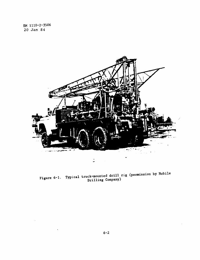
EM 1110-2-3506
20 Jan 84
/’
-.
%
-.
Figure 6-1. T~ical truck-mounted drill rig (permission by Mobile
Drilling Company)
6-2
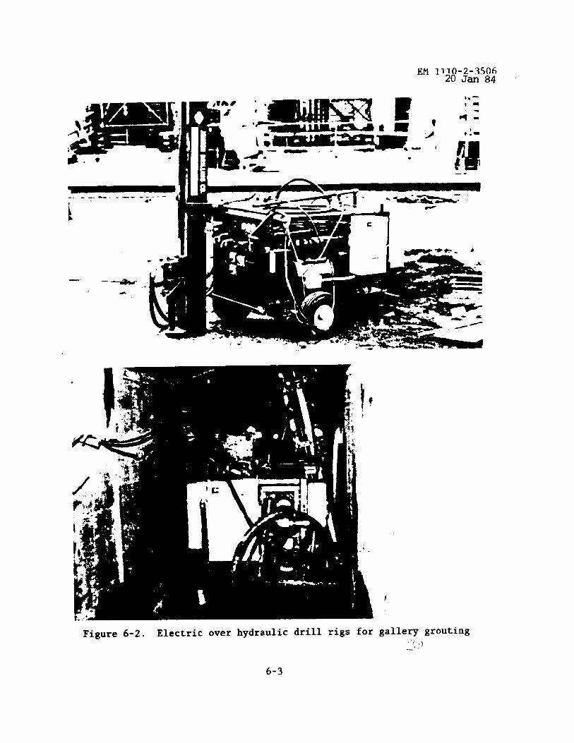
Figure 6-2. Electric over hydraulic drill rigs for
6-3
gallery grouting!,3—’
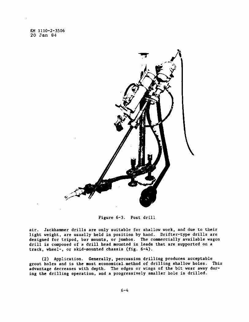
EM 1110-2-350620 Jan 84
*
Figure 6-3. Post drill
air. Jackhammer drills are only suitable for shallow work, and due to theirlight weight, are usually held in position by hand. Drifter-type drills aredesigned for tripod, bar mounts, or jumbos. The commercially available wagondrill is composed of a drill head mounted in leads that are supported on atrack, wheel-, or skid-mounted chassis (fig. 6-4).
(2) Application. Generally, percussion drilling produces acceptablegrout holes and is the most economical.method of drilling shallow holes. Thisadvantage decreases with depth. The edges or wings of the bit wear away dur-ing the drilling operation, and a progressively smaller hole is drilled.
6-4
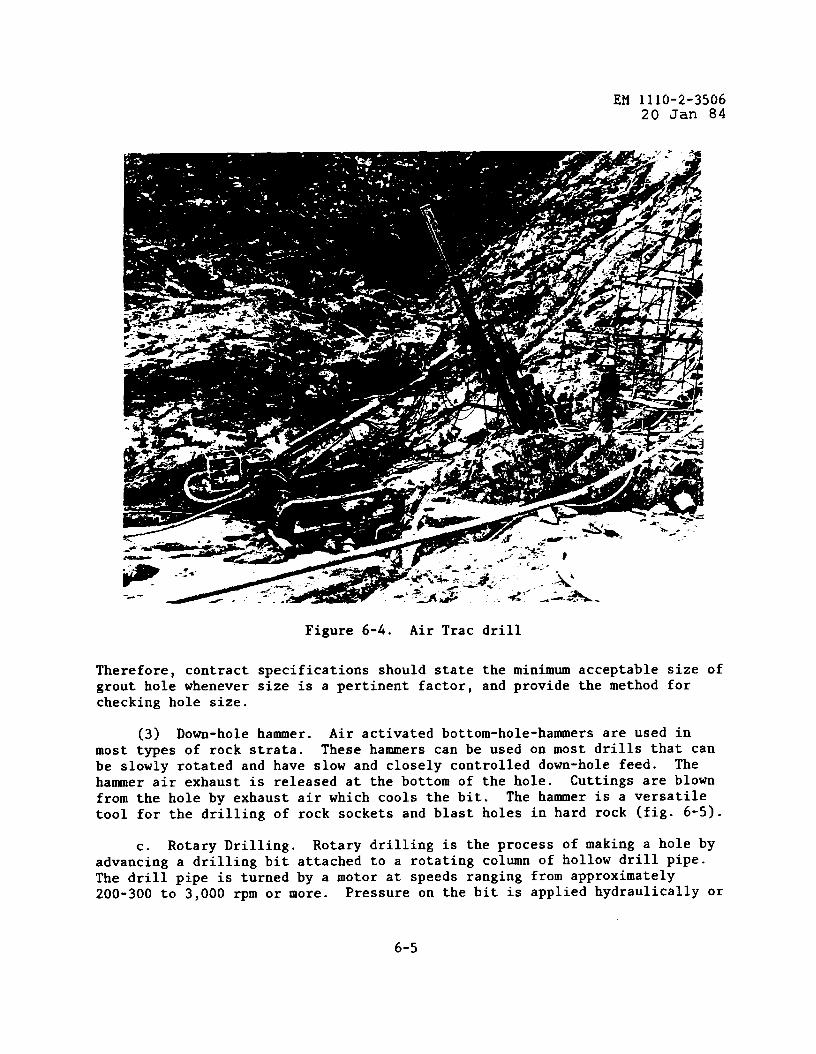
EM 1110-2-350620 Jan 84
Figure 6-4. Air Trac drill
Therefore, contract specifications should state the minimum acceptable size ofgrout hole whenever size is a pertinent factor, and provide the method forchecking hole size.
(3) Down-hole hammer. Air activated bottom-hole-hammers are used inmost types of rock strata. These hammers can be used on most drills that canbe slowly rotated and have slow and closely controlled down-hole feed. Thehammer air exhaust is released at the bottom of the hole. Cuttings are blownfrom the hole by exhaust air which cools the bit. The hammer is a versatiletool for the drilling of rock sockets and blast holes in hard rock (fig. 6-5).
c. Rotary Drilling. Rotary drilling is the process of making a hole byadvancing a drilling bit attached to a rotating column of hollow drill pipe.The drill pipe is turned by a motor at speeds ranging from approximately200-300 to 3,000 rpm or more. Pressure on the bit is applied hydraulically or
6-5
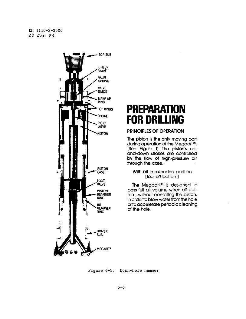
EM 1110-2-350620 Jan 84
PREPMATIONFOR DRILLINGPRINCIPLES OF OPERATION
The piston is the only moving padduring operation of the Megadril@,(See Figure 1) The piston’s up-and-down strokes are controlledby the flow of high-pressure airthrough the case,
With bit in extended position(tool off bottom)
The Megadril@ is designed topass full air volume when off bot-tom, without operating the piston,in order to blow water from the holeor to accelerate periodic cleaningof the hole.
Figure 6-5. Down-hole hammer
6-6
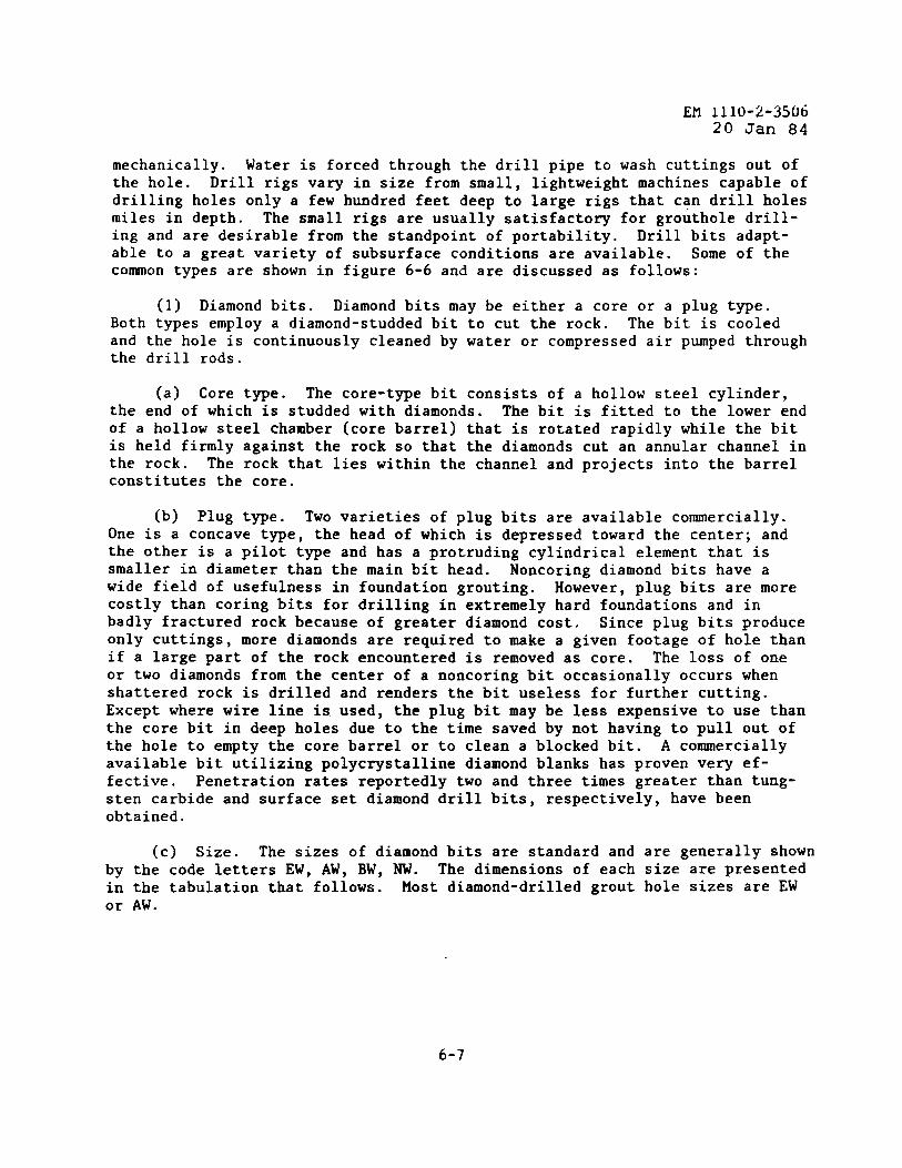
EM 1110-2-350620 Jan 84
mechanically. Water is forced through the drill pipe to wash cuttings out ofthe hole. Drill rigs vary in size from small, lightweight machines capable ofdrilling holes only a few hundred feet deep to large rigs that can drill holesmiles in depth. The small rigs are usually satisfactory for grouthole drill-ing and are desirable from the standpoint of portability. Drill bits adapt-able to a great variety of subsurface conditions are available. Some of thecommon types are shown in figure 6-6 and are discussed as follows:
(1) Diamond bits. Diamond bits may be either a core or a plug type.Both types employ a diamond-studded bit to cut the rock. The bit is cooledand the hole is continuously cleaned by water or compressed air pumped throughthe drill rods.
(a) Core type. The core-type bit consists of a hollow steel cylinder,the end of which is studded with diamonds. The bit is fitted to the lower endof a hollow steel chamber (core barrel) that is rotated rapidly while the bitis held firmly against the rock so that the diamonds cut an annular channel inthe rock. The rock that lies within the channel and projects into the barrelconstitutes the core.
(b) Plug type. Two varieties of plug bits are available commercially.One is a concave type, the head of which is depressed toward the center; andthe other is a pilot type and has a protruding cylindrical element that issmaller in diameter than the ❑ain bit head. Noncoring diamond bits have awide field of usefulness in foundation grouting. However, plug bits are morecostly than coring bits for drilling in extremely hard foundations and inbadly fractured rock because of greater diamond cost. Since plug bits produceonly cuttings, more diamonds are required to make a given footage of hole thanif a large part of the rock encountered is removed as core. The loss of oneor two diamonds from the center of a noncoring bit occasionally occurs whenshattered rock is drilled and renders the bit useless for further cutting.Except where wire line is used, the plug bit may be less expensive to use thanthe core bit in deep holes due to the time saved by not having to pull out ofthe hole to empty the core barrel or to clean a blocked bit. A commerciallyavailable bit utilizing polycrystalline diamond blanks has proven very ef-fective. Penetration rates reportedly two and three times greater than tung-sten carbide and surface set diamond drill bits, respectively, have beenobtained.
(c) Size. The sizes of diamond bits are standard and are generally shownby the code letters EW, AW, BW, NW. The dimensions of each size are presentedin the tabulation that follows. Most diamond-drilled grout hole sizes are EWor AW.
6-7
1
W 1110-2-350620 Jan 84-
LOHE -~PE . - . PUJG TYPE
DIAMOW BITS.,. ..
@,..@”g..~-., ..... ....ROCK BITS
FISHTAILBIT
DRAG #lTS
Figure 6-6. Drill bits
Size, inches Size, mCode Hole Core Hole Core—. ——EW 1-31/64 27/32 37.7 21.5AW 1-57/64 1-3/16 48.0 30.1BW 2-23/64 1-21/32 60.0 42.0Nw 2-63/64 2-5/32 75.7 54.7
Wire line bits listed below,~eld the same size hole but not the same sizecore as the bit shown above.
Size, inches Size, lmICode Hole Core Hole Core— — ——
AQ 1-57/64 1-1/16 48.0 27.0BQ 2-23/64 1-7/16 60.0 36.5NQ 2-63/64 1-7/8 75.7 47.6
(2) Hard ❑etal bits. Drill bits of hardened steel notched to resemblethe teeth of a saw can be placed on the core barrel to substitute for a morecostly diamond bit. In some soft rocks this type of bit makes a hole muchfaster, is not as easily blocked, and is much cheaper than a diamond bit. Theteeth of such bits are often faced with one of the alloys of tungsten carbide,or replaceable inserts of a hard alloy are welded into holes cut into the bitblank. The hard alloys can also be used to make a noncoring bit.
6-8
EM 1110-2-350620 Jan 84
(3) Roller rock bits. Rock bits,bottom of a hollow drill pipe column.
like diamond bits, are attached to theThe bit is made of toothed rollers or
cones, and each turns or rolls on the rock as the bit rotates with the drillpipe. Cutting is accomplished by crushing and chipping operations. The shape,attitude, and number of teeth and the number of rollers vary. Most bits havethree or four cones or rollers; some have two. The teeth and other parts ofthe bits subjected to intense abrasion are made of hard alloys. Cuttings andsludge are washed out of the hole by circulating water or drilling mud throughthe drill pipe and back to the surface between the drill pipe and the walls ofthe hole. The roller rock bit is not extensively used for grouthole drillingbecause the smallest available size is approximately the same as that of anNW-diamond bit.
(4) Drag and fishtail bits. The drag bit is a general service bit forrotary drilling. The bit is capable of drilling soft rock and most soils andis used extensively in foundation explorations and grouthole drilling. Thefishtail bit is so named because of its resemblance to a fish tail. The di-vided ends of the single-blade bit are curved away from the direction of rota-tion. Other drag bits have three or four bladesplaceable.
, which may or may not be re-The cutters or cutting edges of the blades are ❑ade of hardened
steel or are covered with hard alloys. Almost any desired size is available.
(5) Summary. Drill bit types and the materials in which they are gen-erally used are as follows:
Drill Bit Type
DiamondCore
Plug
Hard metal
Rock
Drag and fishtail
Percussion
Principal Use
Rock and concrete
Rock
Soft rock, hard clay,and cemented soils
Rock
Soft rock and soil
Rock and concrete
Not Suited for
Unconsolidated soils
Extremely hard rock,extremely soft rock,unconsolidatedsoils, and shatteredor fractured rock
Hard rock and uncon-solidated soils
Unconsolidated soilsand very hard rock
Hard rock
Unconsolidated soils
e. Auger Drills. The auger drilling rig powers either short, spiral-shaped tool; or drill rods wit~ continuou= heii~al fluting. The spiral-shapedtool is run on a torque bar and serves as a platform to remove cuttings. Thedrill rod acts as a screw conveyor to remove cuttings produced by an
6-9
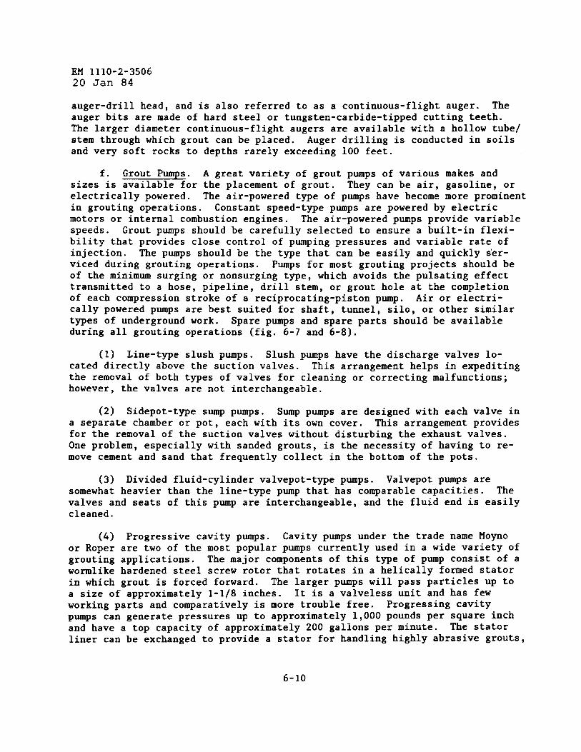
EM 1110-2-350620 Jan 84
auger-drill head, and is also referred to as a continuous-flight auger. Theauger bits are made of hard steel or tungsten-carbide-tipped cutting teeth.The larger diameter continuous-flight augers are available with a hollow tube/stem through which grout can be placed. Auger drilling is conducted in soilsand very soft rocks to depths rarely exceeding 100 feet.
f. Grout Pumps. A great variety of grout pumps of various makes andsizes is available for the placement of grout. They can be air, gasoline, orelectrically powered. The air-powered type of pumps have become more prominentin grouting operations. Constant speed-type pumps are powered by electricmotors or internal combustion engines. The air-powered pumps provide variablespeeds. Grout pumps should be carefully selected to ensure a built-in flexi-bility that provides close control of pumping pressures and variable rate ofinjection. The pumps should be the type that can be easily and quickly ser-viced during grouting operations. Pumps for most grouting projects should beof the minimum surging or nonsurging type, which avoids the pulsating effecttransmitted to a hose, pipeline, drill stem, or grout hole at the completionof each compression stroke of a reciprocating-piston pump. Air or electri-cally powered pumps are best suited for shaft, tumel, silo, or other similartypes of underground work. Spare pumps and spare parts should be availableduring all grouting operations (fig. 6-7 and 6-8).
(1) Line-type slush pumps. Slush pumps have the discharge valves lo-cated directly above the suction valves. This arrangement helps in expeditingthe removal of both types of valves for cleaning or correcting malfunctions;however, the valves are not interchangeable.
(2) Sidepot-type sump pumps. Sump pumps are designed with each valve ina separate chamber or pot, each with its own cover. This arrangement providesfor the removal of the suction valves without disturbing the exhaust valves.One problem, especially with sanded grouts, is the necessity of having to re-move cement and sand that frequently collect in the bottom of the pots.
(3) Divided fluid-cylinder valvepot-type pumps. Valvepot pumps aresomewhat heavier than the line-type pup that has comparable capacities. Thevalves and seats of this pump are interchangeable, and the fluid end is easilycleaned.
(4) Progressive cavity pumps. Cavity pumps under the trade name Moynoor Roper are two of the most popular pumps currently used in a wide variety ofgrouting applications. The major components of this type of pump consist of awormlike hardened steel screw rotor that rotates in a helically formed statorin which grout is forced forward. The larger pumps will pass particles up toa size of approximately 1-1/8 inches. It is a valveless unit and has fewworking parts and comparatively is more trouble free. Progressing cavity
Pws can generate pressures up to approximately 1,000 pounds per square inchand have a top capacity of approximately 200 gallons per minute. The statorliner can be exchanged to provide a stator for handling highly abrasive grouts,
6-10

Efl1110-2-350620 Jan 84
*. .
..
.
. .
0. SIDE-POT-TYPE PuMP .“
,
fCourfesyofWagenefPump Dfv/sion,.CantonSroKerCorp.c~n!on.onto Buliet,nNO W~-lMA )
Figure 6-7. Slush pUllkpS
6-11
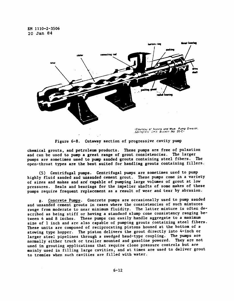
~ 1110-2-350620 Jan 84
Figure 6-8. Cutaway section of progressive cavity pump
chemical grouts, and petroleum products. These pumps are free of pulsationand can be used to pump a great range of grout consistencies. The largerPqs are sometimes used to pump sanded ~routs containing steel fibers. Theopen-throat types are the best suited for handling grouts containing fillers.
(5) Centrifugal pumps. Centrifugal pumps are sometimes used to pumphighly fluid sanded and unsanded cement grout. These pumps come in a varietyof sizes and makes and ard capable of pumping large volumes of grout at lowpressures. Seals and bearings for the impeller shafts of some ❑akes of thesepumps require frequent replacement as a result of wear and tear by abrasion.
g“ Concrete Pumps. Concrete pumps are occasionally used to pump sandedand unsanded cement grouts in cases where the consistencies of such mixturesrange from moderate to near minimum fluidity. The latter mixture is often de-scribed as being stiff or having a standard slump cone consistency ranging be-tween 4 and 8 inches. These pumps can easily handle aggregate to a maximumsize of 1 inch and are also capable of pumping grouts containing steel fibers.These units are composed of reciprocating pistons housed at the bottom of astowing type hopper. The piston delivers the grout directly into 4-inch orlarger steel pipelines through a swedged head-type coupling. The pum’Psarenormally either truck or trailer mounted and gasoline powered. They are notused in grouting applications that require close pressure controls but aremainly used in filling large cavities, and at times are used to deliver groutto tremies when such cavities are filled with water.
6-12
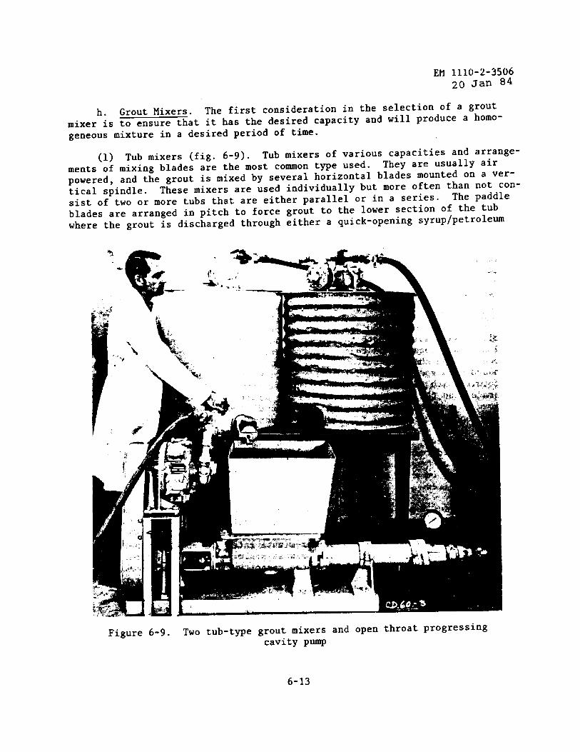
h.mixer is
EM 1110-2-350620 Jan 84
Grout Mixers. The first consideration in the selection of a groutto ensure that it has the desired capacity and will produce a homo-
geneous mixture in a desired period of time.
(1) Tub mixers (fig. 6-9). Tub mixers of various capacities and arrange-
ments of mixing blades are the most common type used. They are usually air
powered, and the grout is mixed by several horizontal blades mounted on a ver-
tical spindle. These mixers are used individually but more often than not con-sist of two or more tubs that are either parallel or in a series.
The paddle
blades are arranged in pitch to force grout to the lower section of the tubwhere the grout is discharged through either a quick-opening syrup/petroleum
Figure 6-9. Two tub-type grout ❑ixers and open throat progressingcavity pump
6-13
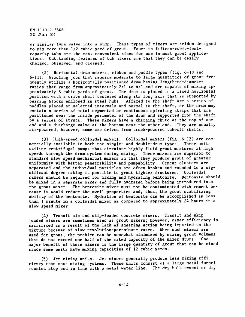
EM 1110-2-350620 Jan 84
or similar type valve into a sump. These types of mixers are seldom designedto mix more than 1/2 cubic yard of grout. Four- to fifteen-cubic-foot-capacity tubs are the most convenient sizes for use in most grout applica-tions. Outstanding features of tub mixers are that they can be easilycharged, observed, and cleaned.
(2) Horizontal drum mixers, ribbon and paddle types (fig. 6-10 and6-11). Grouting jobs that require moderate to large quantities of grout fre-quently utilize a horizontally positioned drum having length-to-diameterratios that range from approximately 2:1 to 4:1 and are capable of mixing ap-proximately 8 cubic yards of grout. The drum is placed in a fixed horizontalposition with a drive shaft centered along its long axis that is supported bybearing blocks enclosed in steel hubs. Affixed to the shaft are a series ofpaddles placed at selected intervals and normal to the shaft, or the drum maycontain a series of metal segmented or continuous spiraling strips that arepositioned near the inside perimeter of the drum and supported from the shaftby a series of struts. These mixers have a charging chute at the top of oneend and a discharge valve at the bottom near the other end. They are usuallyair-powered; however, some are driven from truck-powered takeoff shafts.
(3) High-speed colloidal mixers. Colloidal mixers (fig. 6-12) are com-mercially available in both the single- and double-drum types. These unitsutilize centrifugal pumps that circulate highly fluid grout mixtures at highspeeds through the drum system during mixing. These mixers are superior tostandard slow speed mechanical mixers in that they produce grout of greateruniformity with better penetrability and pumpability. Cement clusters areseparated and the individual particles are often broken and rounded to a sig-nificant degree making it possible to grout tighter fractures. Colloidalmixers should be required for mixing and hydrating bentonite. Bentonite shouldbe mixed in a separate mixer and fully hydrated before being introduced intothe grout mixer. The bentonite mixer must not be contaminated with cement be-cause it would reduce the swell properties and, thus, the grout stabilizingability of the bentonite. Hydration of bentonite can be accomplished in lessthan 1 ❑inute in a colloidal mixer as compared to approximately 24 hours in aslow speed mixer.
(4) Transit mix and skip-loaded concrete mixers. Transit and skip-loaded mixers are sometimes used as grout mixers; however, mixer efficiency issacrificed as a result of the lack of shearing action being imparted to themixture because of slow revolution-per-minute rates. When such mixers areused for grout, the problem can be somewhat minimized by mixing grout volumesthat do not exceed one half of the rated capacity of the mixer drums. Onemajor benefit of these mixers is the large quantity of grout that can be mixedsince some units have mixing capacities of 12 cubic yards.
(5) Jet mixing units. Jet mixers generally produce less mixing effi-ciency than most mixing systems. These units consist of a large metal funnelmounted atop and in line with a metal water line. The dry bulk cement or dry
6-14
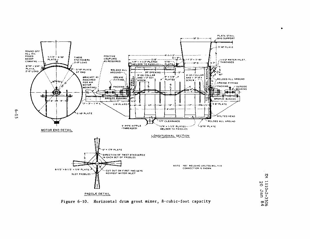
PLATE STEEL
T,
?4G
,+4 “ 4s.
‘.~-, wELOED ALL AROUND
b:,,,, GREAsE FITTING
‘.:’.:,~PACKl NGA ,.. OUTsl DE
BRONZE EuSHING-~,,. .‘.IIF
! ! 1 I 1’1 y,,,,, ~L&TEL !)4- PLATE-W ‘..--6 -.&.- -- 1’2. -- -..*.-. -- 12. .- . ..&.. –. ,2... -.&~.,,2,,.
P. . . . . . . . . . . . . . . .- . . ..- - 49-(12” ------ ------– -------- --- -
1 I )1. A b b -BOLTED NEAO
‘.~/2cLEARANc E ~. , ‘-WELDED ALL AROUND., ./’
I 3,- PIPE NIPPLE y.,- ,.
‘-.114” n !-1/2,, PLATE S-----(TUREAOEDI
-3/ 16,, PLATE
MOTOR END DETAIL WELDED TO PA ODLES
0-!12,, x 0.
i* ‘.6-q X tl~ PLATE
‘-DIRECTION OF TWIST ST AGGEREO~ IN EACH SET O!= PA ODLES
.1/2, x l/4,, pLATE.‘.-CUT OUT ON FIRST TWO SETS
SLOT PA ODLES ‘-’ NEAREST WATER INLET
LONGITUDINAL SECTION
NOTE 100- WELDING UNLESS BOLTED
CONNECTION IS SHOWN
PADOLE DETAIL
Figure 6-10. Horizontal drum grout mixer, 8-cubic-foot capacity
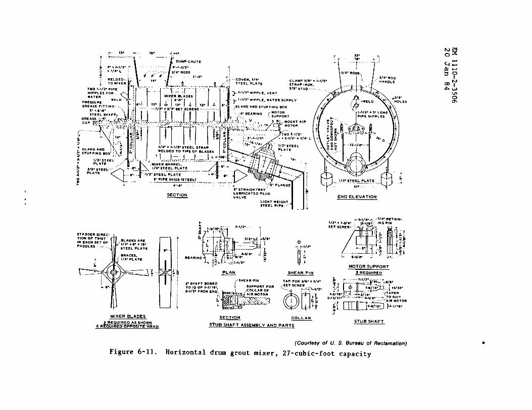
“ !/4. L ;
\
. . . . . . .. ,
/
~ ~. ~. -3!4.Roos 2,.5.WELDEO.. .Z . . . .
\S/4- ROO, j
TWO 1-1/2. PIP12MfippLEs FOR. ~
0m
GREASE FIT TIN G-. j“ , 16-.:. 112.1+112.
-,!. II ‘~ELLYEO TO TIPS Oi ❑ ,AD,. i & - /&
‘..MIxEROAISREL,. : e..S18. ST EEL-. ““ — .— –_Q P“-t14. 5TEEL PLATE---.4 z- ‘ ‘h , :.g, ::
PLATC& s.. -1/2. SrCCL pLATE
o fu a.S. PIPI! SKIDS I$TC12L)— —-—.—— ————
: i,, .
4,.s. .
- /-{
‘::5. FLANGE6. STRAIGISTWAV
SECTION LUORICATEO PLUG
VALVE END ELEVATION,, LIGHT WEIGHT
STEEL PIPE..<’i 1’.— 1
STAGGER OIREC-
+
TION 0? TWISTIM CACN SETOF .BLADES ARC
PAOOLCS .. . . . .. ..“814. MC. .16.
STEEL PLATE
WRACES,. ( 1/4. PLATE
e:-:.. )): .=____ ‘;.
. 6...
MOTORSUPPORT2 REQUIREDPLAN SHEAR PIN
TAP FOR 3/e. s S/6... SET SCREW
:..:< ).t/2.
60”
....
I’ iii f
MlxER BLAOES2 REQuIRED AS SHOWN
2 RmUIREO~lT E H~ND
SECTION COLLARSTUB SHAFT
STUB SHAFT ASSEMBLYANO PARTS
(Courtesy of U. S. Bureeu of Reclamation) ●
Figure 6-11. Horizontal drum grout mixer, 27-cubic-foot capacity
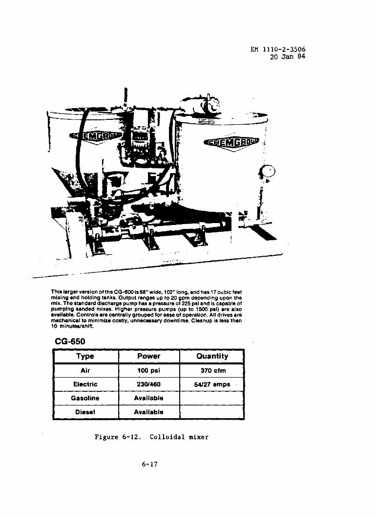
EM 1110-2-350620 Jan 84
,.
This larger version of the CG-600 is 68” wide, 102” long, and has 17 cubic feetmixing and holding tanks. Output ranges up to 20 gpm depending upon themix. The standard discharge pump has a pressure of 225 psi and is capable ofpumping sanded mixes. Higher pressure pumps (up to 1500 psi) are alsoavailable. Controls are centrally grouped for ease of operation. All drives aremechanical to minimke costly, unnecessary downtime. Cleanup is less than10 minutee/shift.
CG=650/
Type Power Quantity1
Air 100psi 370cfm
Electric 2301460 W27 amps
Gasoline Available
Diesel AvailableF
Figure 6-12. Colloidal mixer
6-17

EM 1110-2-350620Jan 84
bulk blended grout materials are continuously metered into the fumel by meansof a flapper valve. A forced stream of mixture water is continuously meteredby pipe just below the orifice of the funnel which causes shearing and tur-bulent mixing action. The resulting mixture is jetted into a holding tank, ismeasured for designed weight and fluidity, and, if needed, is adjusted for cor-rections to cement and water metering. When the mixture is properly adjusted,the suction side of large pumps picks up and transfers the grout to a dis-charge pump. Large volumes of grout can rapidly be placed using this method.This unit 1s some~imes used to place quick-~ett~ng mixtures;ing tanks are in the system. A sampling “T” for providing ais in line.
(6) Compressed-air tank ❑ixers. Compressed-air mixers
ho<ever, no hold-degree of control
are occasionallyused for accu~ate batching and mixing. Th~se types of mixers may range in c~-pacity from a few cubic feet to 500 cubic feet. Dry ❑aterials are fed to thetank through a pipe comection located at the tank side below the water level.Air and mixing water provided through vertical connections discharge into theinterior of the tank. The air-mixed grout is discharged from a connection lo-cated at the base of the mixing cone.
i. Agitator Holding Tanks. To provide a high volume and continuous in-jection of grout, two mixers are usually set up to alternately discharge intoan agitator holding tank that has a capacity at least two and preferably up tothree times the capacity of the mixil~gsystem. Tub or horizontal type mixersoperated at slow speeds are frequently used for agitating holding tanks. Agi-tator holding tanks can be similar in design to the tub-type mixers shown infigure 6-9. Volumes of grout used from the agitator holding tanks can be mea-sured by marks at different levels in the tanks.
j. Grout Lines. Two primary arrangements of grout piping are used tosupply grout from the pump to the hole. The simpler of the two, the single-line system, is used in a variety of grout placements. The system consists ofa pipe or a hose or 5 combination of both extending from the pump discharge tothe header at the hole collar. The pump speed controls the rate of grout in-jection. The second arrangement, which provides a circulating system, is com-posed of a double line, and one of the lines serves as a return line from theheader to the grout pump, sump, or holding tank. This line provides for thecontinuous circulation of the grout through the single line and pump. Thedouble-line system can also be used to meter a desired amount of grout down-hole by simply varying the openings of a valve on the return line withoutchanging pump speed. Pressure is controlled by one or more valves on the con-trol line. A circulating grout header should normally be required for founda-tion grouting.
(1) Hose lines most commonly used for discharge and suction are theflexible type, usually made of reinforced rubber or plastic. The inside diam-eter of these hoses for mostThe larger the diameter of a
grouting applications ranges from 1 to 2 inches.given type of hose, the less the working pressure.
6-18
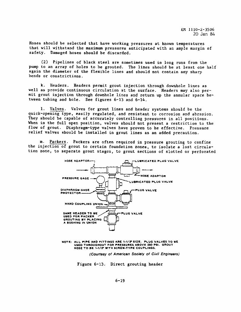
EM 1110-2-350620 Jan 84
Hoses should be selected that have working pressures at known temperaturesthat will withstand the maximum pressures anticipated with an ample margin ofsafety. Damaged hoses should be discarded.
(2) Pipelines of black steel are sometimes used in long runs from thepump to an array of holes to be grouted. The lines should be at least one halfagain the diameter of the flexible lines and should not contain any sharpbends or constrictions.
k. Headers. Headers permit grout injection through downhole lines aswell as provide continuous circulation at the surface. Headers may also per-mit grout injection through downhole lines and return up the annular space be-tween tubing and hole. See figures 6-13 and 6-14.
1. Valves. Valves for grout lines and header systems should be thequick-opening type, easily regulated, and resistant to corrosion and abrasion.They should be capable of accurately controlling pressures in all positions.When in the full open positionflow of grout.
, valves should not present a restriction to theDiaphragm-type valves have proven to be effective. Pressure
relief valves should be installed in grout lines as an added precaution.
m. Packers. Packers are often required in pressure grouting to confinethe injection of grout to certain foundation zones, to isolate a lost circula-tion zone, to separate grout stages, to grout sections of slotted or perforated
PRESSIJRE GAGE
DIAPHRAGM GAGE pLUG VALVEPROTECTOR
HAND COUPLING UNION
SAME HEADER TOBE
3
pLUG VALVEUSED FOR PACKERGROUTING BY PLACING
%
)!A BUSHING IN UNION
U
NOTE: ALL PIPE AND FITTINGS ARE l-1/?SIZE. PLUG VALVESTOBEUSEDTMROUGHOUT FOR PRESSURES ABOVEZSO PSI. GROUTHOSETOBE I-lIPWITH SCREW-TYPE COUPLINGS.
(CourtesyofAmericanSociety of Civil Engineers)
Figure 6-13. Direct grouting header
6-19
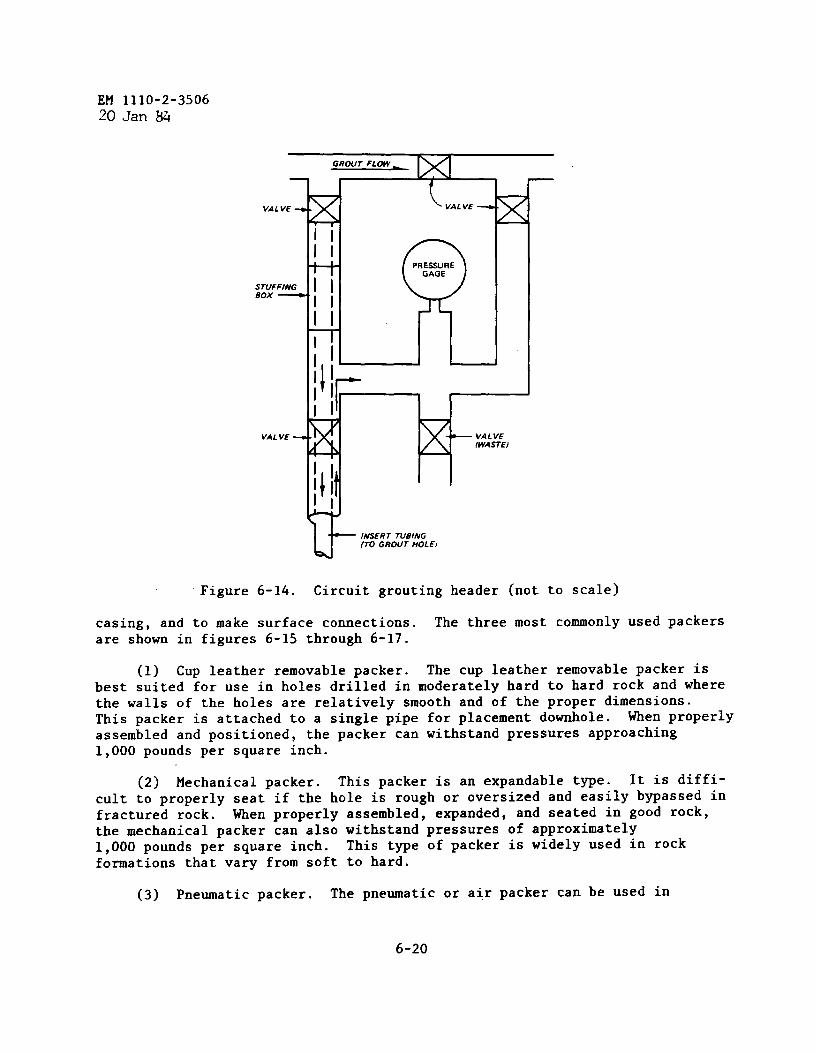
EM 1110-2-350620 Jan W
Figure 6-14. Circuit grouting header (not to scale)
casing, and to make surface comections. The three most commonly used packersare shown in figures 6-15 through 6-17.
(1) Cup leather removable packer. The cup leather removable packer isbest suited for use in holes drilled in moderately hard to hard rock and wherethe walls of the holes are relatively smooth and of the proper dimensions.This packer is attached to a single pipe for placement downhole. When properlyassembled and positioned, the packer can withstand pressures approaching1,000 pounds per square inch.
(2) Mechanical packer. This packer is an expandable type. It is diffi-cult to properly seat if the hole is rough or oversized and easily bypassed infractured rock. When properly assembled, expanded, and seated in good rock,the mechanical packer can also withstand pressures of approximately1,000 pounds per square inch. This type of packer is widely used in rockformations that vary from soft to hard.
(3) Pneumatic packer. The pneumatic or air packer can be used in
6-20
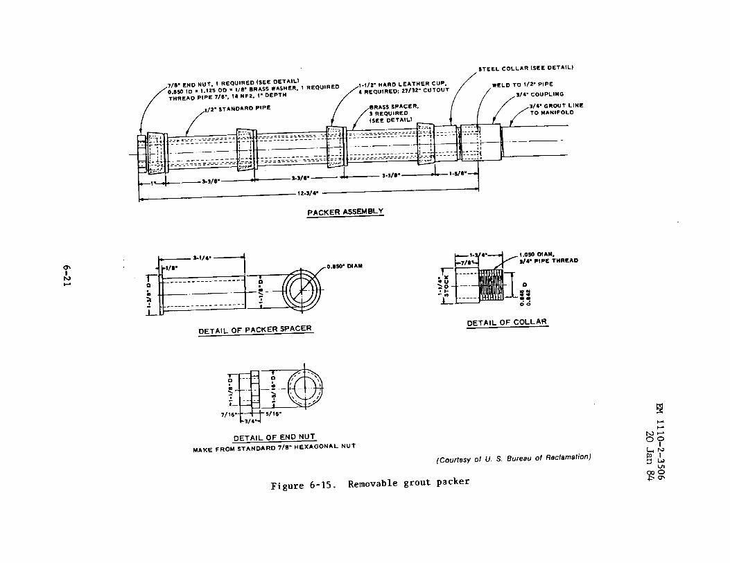
sTEEL COLLAR (SEE OETAIL)
7/9. ENo NUT, f REou!RED (sEE oETAIL)~ta~ 10 x 1.12s 00 x 1/8” BRASSWASHERo1 REQulREo
1-1/2” HARD LEATHER CUP. WELO 10 1/2” plpE4 REQUIREO: 27!S2” CuTou7
THREAD plpE 7/0”. 14 ‘F2’ 1“ ‘EPTH3/4- COUPLING
,/2’I ST ANOARo PIPE S/49 GROUT LINE10 MANIFOLD
________===-- , ---.----—----- ------------- ..— — -
!! .-----..— —. t ------------__ . ---—-----
--~~a-’”o
●
PACKER ASSEMBLY
DETAIL OF PACKER SPACER
1.0s001AM,S149 PIPE THREAD
o
::
66
DETAIL OF COLLAR
DETAIL OF END NUT
MAKE FROM STANDARD 7/8” HEXAGONAL NuT
(Courtesy 0/ U. S. Bureau of Reclamation)
Figure 6-15. Removable grout packer
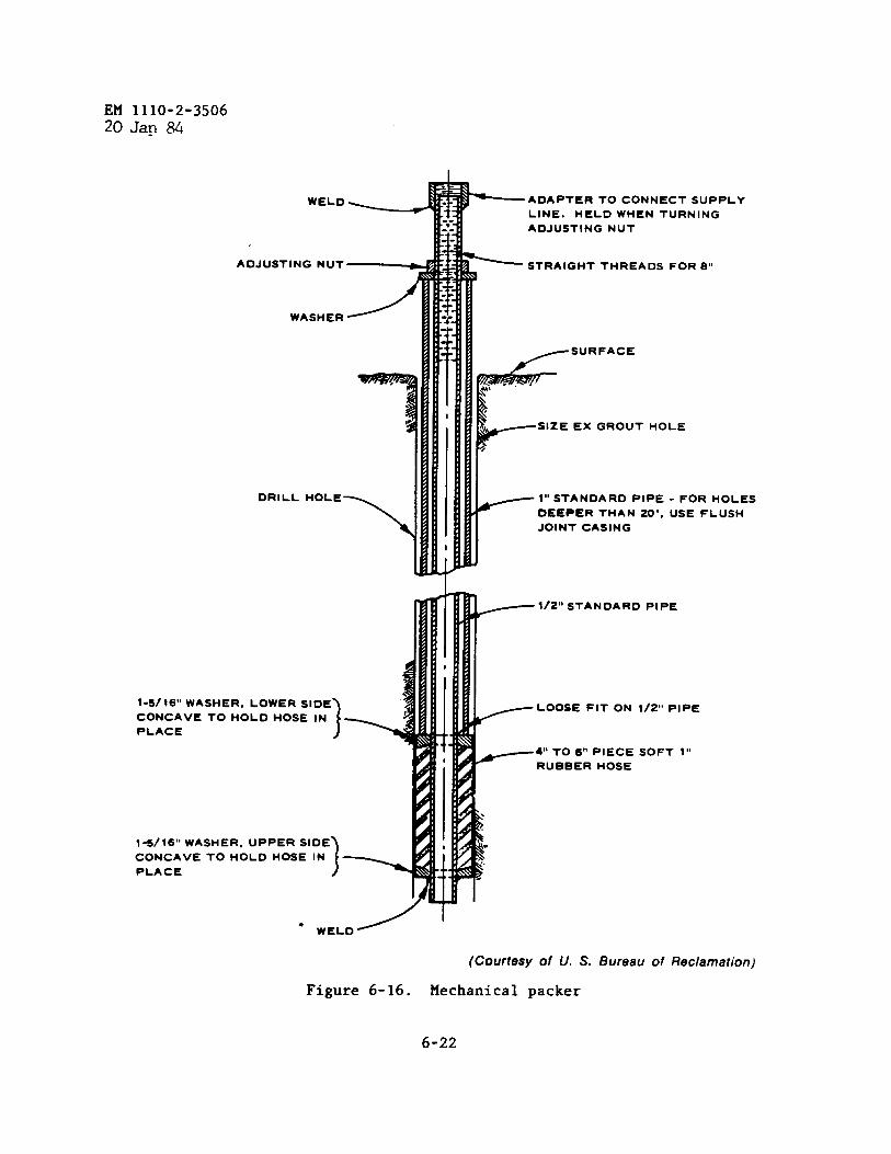
EM 1110-2-3506Z()J~g ~
ADJUSTING NUT—
~A~H’~~
DRILL HOLE
\
\1-s/16” WASHER. LOWER SIDE
CONCAVE TO HOLD HOSE IN
)4
I
PLACE
1-s/16” WASHER, UPPER SIDE) I
~ STRAIGHT THREADS FOR e“
F SIZE ‘X GROUT HOLE
>
_ 1“ STANDARD PIPE
DEEPER THAN 20’,
JOINT CASING
- FOR HOLES
USE FLUSH
~ 1/2” STANDARD PIP’
CONCAVE TO HOLD HOSE INPLACE J
3
.
● WELD
i 1< ‘00s’ FIT ON 1/2” PIPE
4“ TO 6“ PIECE SOFT III~RUB13ER HOSE
(Courtesy of U. S. Bureau of Reclamation)
Figure 6-16. Mechanical packer
6-22

EM 1110-2-350620Jan ~
ASSEMBLY
TAPE 3/ Sl- AIR SUPPLY
LINE TO PACKER PIPE ‘---- ~~,
t/2- sTANDARD PlpE. ..----.:;~.;~
[“my,~‘ k
CONNECTION-COPPER !1TuBE TO RuBBER TuBE ----.7.;,. ~
ii~~114- COPPER TuBE EM-EEDDEO IN SLOT IN SHELL
.k~ )OF 1/2- PIPE AND BRA ZED...
!: I ~ !4”””-
SECTION ALONG C
9P.-COMPRESSEO AIR BOTTLE; WITH REGULATOR
m
k“1 ;..3/8. AIR
r
-SUPPLY LINE
....SUPPLY HOSE-y .-RETURN LINE
PRESSURE ‘-@ 1: ;. “ALVE5GAGE ~d:..,
---PAC.ER C’-’”p
r:——-——,~
;b .
t: :;:,’;/
\
T S7ANOAR0 PIPE ‘-- ..:- , . ; ,coNcRETEEMOEOOEO INFOOTING
‘; j~’f”:f” ‘~FJGwALL
,7, ‘,-. ,.
>60, ”‘- ‘+
.,’. ~t1-3/8q MINIMUM”” ‘::OIAM HOLE f;,
,.
I
TYPICAL VIEW OF LAYOUT
CROSS SECTION OF AIR-PACKERRuBBER TUBE
LOW MODULUS OF ELASTICITY ANO
HIGH TENSILE STRENGTH
NOTE: LENGTH OF AIR-PACKER RUBBERTUOE vARIABLE.
GROUT SUPPLY LINE-3f4” RUEBERHOSE UP TO 60- DEPTH, AND 31*”PIPE FOR GREATER DEPTH liOLE.
OIAMETER OF PACKER ANO CON-NECTIONS TO ❑ E LESS THAN MI Nl-SSUM OIAMETER OF HOLE.
(Courtesy of
Figure 6-17. Air packer
U. S. Bureau of Reclamation)
6-23

EM 1110-2-350620 Jar)84
oversized holes because of its expansivity. As an example, an EM size may beseated in 3- or 4-inch-diameter hole or casing, providing that the hole condi-tion is good. The packer is well suited for use in soft, fractured, and thin-bedded rocks. Grout injection pressure should be less than packer inflationpressure to prevent bypass of the grout.
n. Centralizers. Centralizers are sometimes required to position casingor injection pipe in the center of holes, particularly when casing or pipe isto be a part of a permanent subsurface type of installation. Assembled leafsprings with limit rings serve as centralizers and provide a uniform annulusaround the casing or the pipe, which can then be properly filled with grout.The centralizers aid casing and pipe to negotiate irregularities and doglegs.Commercially available centralizers are fabricated with hinges to facilitatetheir attachment to casing or pipe strings (fig. 6-18).
Figure 6-18. Centralizers,Courtesy Halliburton, Inc.
o. Tube Wiping/Displacement Plugs. Tube plugs are used in special grout-ing applications for displacement of a measured amount of grout down a hole.A hard rubber plug with a series of rubber discs is forced down the inside ofa steel tube by a fluid head acting on a steel ball seated atop the plug. Theball and plug are discharged into grout or retained in a plug catcher attachedto the bottom of the drill tubing.,
P“ Asphalt Grouting Equipment. Portable asphalt heating kettles commonlyused by contractors for pavement crack sealing, roofing coatings, and similarapplications have served well in heating asphalt for grouting (fig. 6-19). Hotasphalt heating should be maintained below the flash point of the asphalt.
6-24
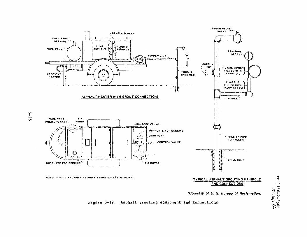
STEAMRELIEF
FuEL TANKOPENING---
FUEL TANK ““’f\
KEROSENiHEATER
—...
1-1 ,> BAFFLE SCREEN
,SUPPL
~ LINE,,4..
1----......._-.--–u.—_–_ -. / ....... ..hASPHALT HEATER WITH GROUT CONNECTIONS
FuEL TANK —..—— .— ----
PREsSURE GAGE .Pt;P f- )SHUTOFF VALVE~’---- -——.
:.. I 3/O”PLATEFOROECKING
L.-——2
NOTE: l-f/2”STANOARDPlPEAND FITTINGS EXCEPT AS SHOWN.
AIR MOTOR
—
VALVE----
~--<l
—
(Courtesy of U.S.
Figure 6-19. Asphalt grouting equipment and connections
PRESSUREGAGE-.
HEAVY OIL
l-NIPPLE
HEAVY GREASE
...‘NIPPLE OR PIPE
TO PACKER
i
T.---—.—7. 7TS
;: :
::?.
51; DRILL HOLE
:. .,.::’.
TYPICAL ASPHALT GROUTING MANIFOLD E
AND CONNECTIONS --
w-
Bureau ofRec/amation)o?~y‘g:
gz
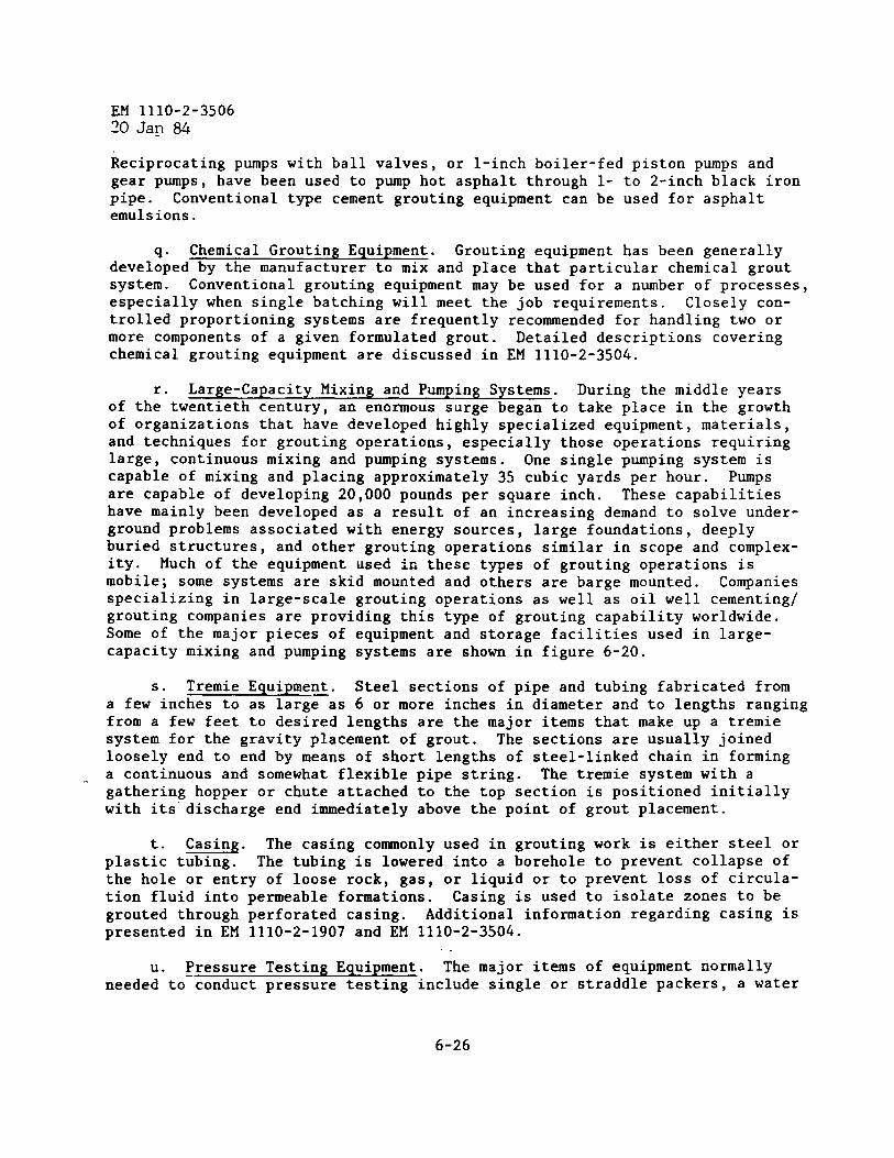
EM 1110-2-350620 Jan 84
Reciprocating pumps with ballgear pumps, have been used to
valves, or l-inch boiler-fed piston pumps andpump hot asphalt through 1- to 2-inch black iron
pipe. Conventional type cement grouting equipment can be used for asphaltemulsions.
q“ Chemical Grouting Equipment. Grouting equipment has been generallydeveloped by the manufacturer to mix and place that particular chemical groutsystem. Conventional grouting equipment may be used-for a number of pro~esses,especially when single batching will meet the job requirements. Closely con-trolled proportioning systems are frequently recommended for handling two ormore components of a given formulated grout. Detailed descriptions coveringchemical grouting equipment are discussed in EM 1110-2-3504.
r. Large-Capacity Mixing and Pumping Systems. During the middle yearsof the twentieth century, an enormous surge began to take place in the growthof organizations that have developed highly specialized equipment, materials,and techniques for grouting operations, especially those operations requiringlarge, continuous mixing and pumping systems. One single pumping system iscapable of mixing and placing approximately 35 cubic yards per hour. Pumpsare capable of developing 20,000 pounds per square inch. These capabilitieshave mainly been developed as a result of an increasing demand to solve under-ground problems associated with energy sources, large foundations, deeplyburied structures, and other grouting operations similar in scope and complex-ity. Much of the equipment used i~ these types of grouting operations ismobile; some systems are skid mounted and others are barge mounted. Companiesspecializing in large-scale grouting operations as well as oil well cementing/grouting companies are providing this type of grouting capability worldwide.Some of the major pieces of equipment and storage facilities used in large-capacity mixing and pumping systems are shown in figure 6-20.
s. Tremie Equipment. Steel sections of pipe and tubing fabricated froma few inches to as large—as 6 or more inches in diameter and to lengths rangingfrom a few feet to desired lengths are the major items that make up a tremiesystem for the gravity placement of grout. The sections are usually joinedloosely end to end by means of short lengths of steel-linked chain in forming
- a continuous and somewhat flexible pipe string. The tremie system with agathering hopper or chute attached to the top section is positioned initiallywith its discharge end immediately above the point of grout placement.
t. -“ The casing commonly used in grouting work is either steel orplastic tubing. The tubing is lowered into a borehole to prevent collapse ofthe hole or entry of loose rock, gas, or liquid or to prevent loss of circula-tion fluid into permeable formations. Casing is used to isolate zones to begrouted through perforated casing. Additional information regarding casing ispresented in EM 1110-2-1907 and EM 1110-2-3504.
u. ~ressure Testing Equipment. The major items of equipment normallyneeded to conduct pressure testing include single or straddle packers, a water
6-26
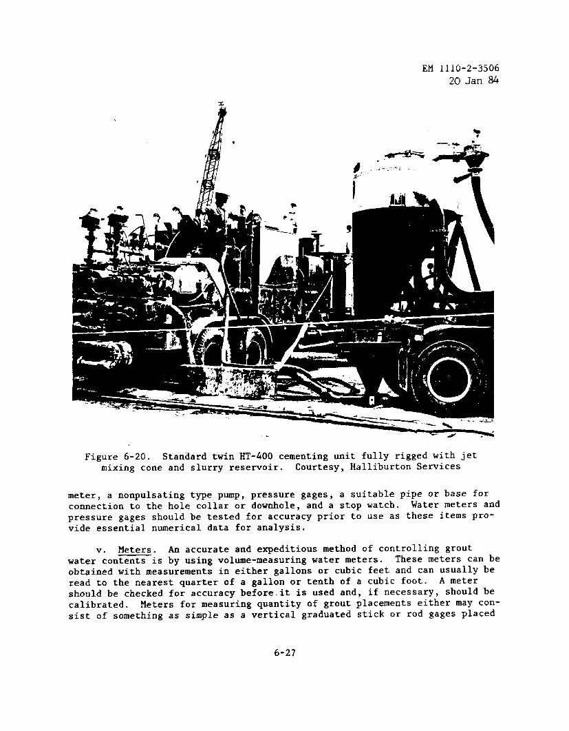
EM 1110-2-350620Jan %
Figure 6-20. Standard twin HT-400 cementing unit fully rigged with jetmixing cone and slurry reservoir. Courtesy, Halliburton Services
meter, a nonpulsating type pump, pressure gages, a suitable pipe or base forcomection to the hole collar or downhole, and a stop watch. Water meters and
pressure gages should be tested for accuracy prior to use as these items pro-vide essential numerical data for analysis.
v. Meters. An accurate and expeditious method of controlling groutwater contents is by using volume-measuring water meters. These meters can be
obtained with measurements in either gallons or cubic feet and can usually beread to the nearest quarter of a gallon or tenth of a cubic foot. A meter
should be checked for accuracy before.it is used and, if necessary, should becalibrated. Meters for measuring quantity of grout placements either may con-sist of something as simple as a vertical graduated stick or rod gages placed
6-27
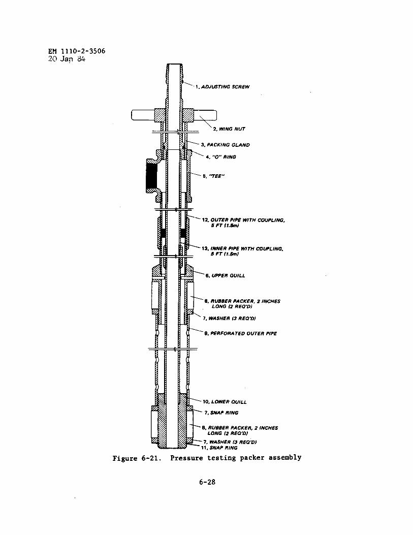
EM 1110-2-350620 Jan d4
1-1, ADJ~T/NG SCREW
R 2, WING NUT
F
3, PACKING GUND
4. “’O RING
‘- 6, ‘TEF’
—
F12. OUTER PIPE WITH COUPLING.
S FT (l.&n)
13, INNER PIPE WITH mlJPLING,6 FT fl.6m)
k“8. RUBBER PACKER,LONG (2 REO”D)
7, WASHER (3 REO”D)
2 INCHES
Ly 9, PERFORA TED OUTER PIPE
r
F10, LOWER QUILL
7, SNAP RING
K8, RUBBER PACKER. 2 INCHESLONG (2 REQ’D)
7. WASHER (3 REQ;D)11. SNAP RING
Figure 6-21. Pressure testing packer assembly
6-28
EM 1110-2-350620 Jan 84
in mixers or agitator trucks, or may use calibrated spindles placed in thegrout line and geared to counters or strip recorders (fig. 6-21). Thesemeters may be designed to measure barrels, cubic feet, gallons, or fractionsof these units.
w. Pressure Gages.
(1) Pressure gages are essential in virtually all types of grouting andpressure testing, and they must be reliable. Malfunctioning gages have re-sulted in damage to structures and rock formations as a result of excessivepressures. Gages should be tested for accuracy prior to use and periodicallyduring the work. The moving parts of the gage should be protected from dustand grit and from direct contact with the grout.
(2) Gages that are available commercially consist of diaphragm systemsto provide the necessary protection. A diaphragm glycerin-filled gage saveris shown in figure 6-22.
6-3. Special Monitoring Equipment. A structure has precise, measurable dimen-sions in virtually all respects; however, the foundation of the structure canonly be described in general terms. The quality of grout being placed in thefoundation and the location, ❑ovement, and behavior of grout in place may needconstant monitoring during a grouting operation. Some of the monitoringmethods in use are described below.
a. Grout Level Detection Equipment. Monitoring the progress and ade-quacy of subsurface grouting operations is extremely important under some cir-cumstances; i.e., grouting voids under structures which must be completelyfilled with grout. Such monitoring can be accomplished by grout level detec-tion systems that include electronic readouts from probes located in an arrayof satellite drill holes surrounding the grout injection hole. The probesusually consist of electrode pairs that measure capacitance or resistance offreshly placed grouts. These probes, prior to placement downhole, are cali-brated in air, water, mud, diluted grout, and the designed grout. With thesedata available, the system can be used to determine the quality of the groutbeing placed, and its vertical and lateral movements. The data also provideinformation relative to decisions to modify mixtures during placement, such asto use a quicker or slower setting mixture, to increase or decrease density,to add lost circulation material, and to incorporate tracers. Remote record-ings can be obtained on printers or oscilloscopes. One application of groutlevel detection equipment is presented in WES MP SL-79-23 (app A).
b. Downhole Temperature Measurements. Temperature profiles of the sub-surface area to be grouted are very helpful in furnishing information on theanticipated effects of temperatures on the setting times of grouts. Thermo-couples or thermistors left in place will indicate the presence of grout as aresult of te~erature rise caused by the hydration of the cement or the reac-tion of the catalyst system in chemical grouts.
6-29
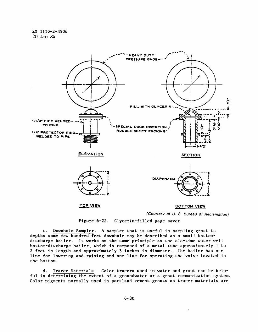
EM 1110-2-350620Jan 84
----,- -
I ==-- ‘W ‘HEAVY DUTY. .
PRESSURE GAGE--4’ L\
xm “$.l-1/2n PIPE WELDED ---
TO RING
1/4” PROTECTOR RINGS
WELOED TO PIPE
* T>
FILL WITH GLYCERIN -..-. 4
\ 0 -------------
-----~ ::=---T----.* ‘
/ --~-:-;i=
‘SPECIAL DUCK INSERTION ,IJ~--
% :& >RUBBER SHEET PACKING- s?---,
7-3-;
-:3-k
ELEVATION SECTION
DIAPHRAG
TOP VIEW BOTTOM VIEW
(Courtesy of U. S. Bureau of Reclamation)
Figure 6-22. Glycerin-filled gage saver
c. Downhole Sampler. A sampler that is useful in sampling grout todepths some few hundred feet downhole may be described as a small bottom-discharge bailer. It works on the same principle as the old-time water wellbottom-discharge bailer, which is composed of a metal tube approximately 1 to
2 feet in length and approximately 3 inches in diameter. The bailer has oneline for lowering and raising and one line for operating the valve located inthe bottom.
d. Tracer Materials. Color tracers used in water and grout can be help-ful in determining the extent of a groundwater or a grout communication system.Color pigments normally used in portland cement grouts as tracer materials are
6-30
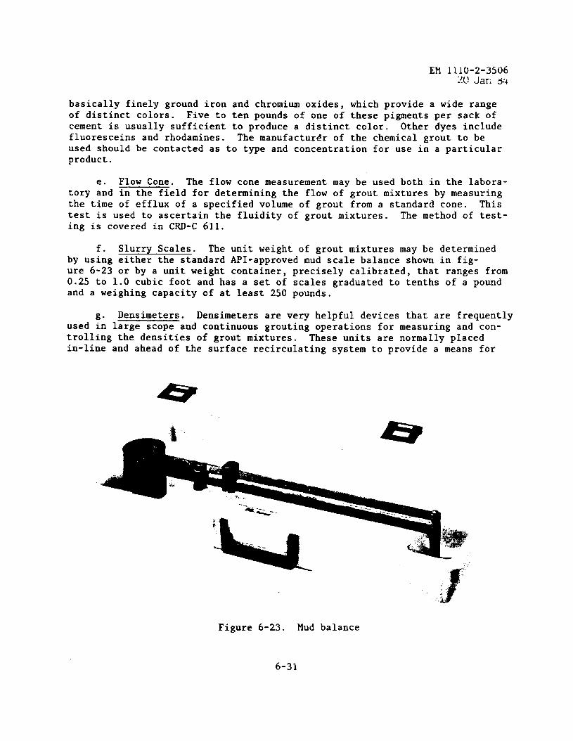
EM 1110-2-35061!(JJar,34
basically finely ground iron and chromium oxides, which provide a wide rangeof distinct colors. Five to ten pounds of one of these pigments per sack ofcement is usually sufficient to produce a distinct color. Other dyes includefluoresceins and rhodamines. The manufacturer of the chemical grout to beused should be contacted as to type and concentration for use in a particularproduct.
e. Flow Cone. The flow cone measurement may be used both in the labora-tory and in the field for determining the flow of grout mixtures by measuringthe time of efflux of a specified volume of grout from a standard cone. Thistest is used to ascertain the fluidity of grout mixtures. The method of test-ing is covered in CRD-C 611.
f. Slurry Scales. The unit weight of grout mixtures may be determinedby using either the standard API-approved mud scale balance shown in fig-ure 6-23 or by a unit weight container, precisely calibrated, that ranges from0.25 to 1.0 cubic foot and has a set of scales graduated to tenths of a poundand a weighing capacity of at least 250 pounds.
g“ Densimeters. Densimeters are very helpful devices that are frequentlyused in large scope and continuous grouting operations for measuring and con-trolling the densities of grout mixtures. These units are normally placedin-line and ahead of the surface recirculating system to provide a means for
Figure 6-23. Mud balance
6-31
EM 1110-2-350620Ja~ 84
adjusting mixtures to designed densities. The devices operate on variousprinciples; one such device is designed on the principle of a force-balancedU-tube; a second operates on a radioactive source. Both systems are equippedwith remote continuous readouts.,
h. Slmp Cone. The consistency of very thick grouts may be determinedby measuring the slump. The cone is a metal frustum that has a base ofeight inches, a top of four inches, and a vertical height of 12 inches. Thegrout is placed in the cone in three equal layers, and each layer is rodded25 times. The cone is removed vertically, and the slump of the grout is mea-sured in inches from the top of the slump cone to the top of the grout. Thismethod of test for slump is described in CRD-C 5.
i. Air Content Measurements. There are five methods that may be usedfor determining the air content of portland cement grout mixtures: gravi-metric, high pressure, micrometric, pressure, and volumetric. These methodsare described, respectively, in CRD-C 7, C 83, C 42, C 41, and C 8. MethodsCRD-C 7, C 41, and C 8 are for freshly mixed grout and CRD-C 83-58 and C 42-83are for hardened grout air contents, usually determined in the laboratory.
j. Time-of-Setting Apparatus. The initial and final sets of portlandcement grouts are determined by the use of a mechanical device known as theVicat apparatus. The apparatus is designed to measure with time the depth ofpenetration or no penetration of a blunt needle into a small cuplike receptaclecontaining a sample of the grout. This test can be conducted in the labora-tory or field. The method of test is described in CRD-C 614.
6-32
APPLICATION TO
7-1. Concrete Dams.
EM 1110-2-350620 Jan $4
CHAPTER 7WATER RETENTION STRUCTURES
a. Preparation for Grouting.
(1) Excavation for concrete structure foundations should be closely con-trolled to prevent damage to the rock. Final grade should be approached withgreat care to prevent damage by blasting and to minimize the necessity forfoundation treatment. If consolidation grouting is required, it should beperformed prior to final cleanup of the foundation. The cleaning and groutingof existing exploratory holes should also be performed at this time. The rocksurfaces should be cleaned sufficiently so that grout surface leaks can befound and caulked.
(2) Under some conditions where open fractures exist in the foundation,pipe embedded in the fracture prior to concrete placement, and running to thegallery for future grouting, may be desirable. At least two pipes shouldusually be set, so that one will provide a return and serve as a telltale dur-ing grout placement. Large solution cavities should be cleaned and eitherbackfilled with concrete, or with gravel and then grouted. Additional pipeshould be run to the gallery for future grouting. Just prior to concreteplacement the grout pipe and drain pipe shauld be set and run to the gallerygutter form.
(3) Exposed final rock surfaces that are subject to deterioration shouldbe protected within an established exposure time limit.
b. Grouting Patterns. A typical profile and section of a main grout cur-tain under a sizable concrete dam is shown in figure 7-1. The notes on thisfigure relative to the size and the spacing of holes and to the order of opera-tions will not apply to grouting under all concrete dams, but are generallyrepresentative of the more common practices. The extent of treatment may varyfrom no grouting to a multiple-line curtain and to area grouting treatment(B-holes in fig. 7-1) depending upon the particular project conditions. Thecurtain produced by drilling and grouting the C-holes in figure 7-1 preventsthe grout from traveling too far upstream from the dam and greatly reduces theamount of seepage flow in horizontally fractured formations. Grouting underpower plants and navigation lock structures is often done to effect a reduc-tion in uplift or to facilitate unwavering operations. A grout curtain supple-mented by a drainage system will normally suffice in both cases.
c. Schedule for Grouting Operations. The construction stage at which toperform foundation grouting is a matter of judgment and depends on the purposeof the grouting to be done, the foundation conditions, and the type of struc-ture. Area grouting is generally done before concrete placement. On theother hand, curtain grouting or grouting for leakage or uplift control is
7-1

TYPICAL PROFILE OF GROUT HOLES NEAR AxIS OF CONCRETE OAMALL emwl mats MOT SW*N
-q \b.ll iill
J--m41, I
SECTION A - A
#l ~, GA,LE.v
‘m
SECTION A-A
Figure 7-1., Multiple line cutoff.....
inom
EM 1110-2-3506ZOJan M
commonly done after concrete has been placed to a considerable height or evenafter the structure has been completed. This is especially true for highstructures where the superimposed load allows the use of grouting pressuresconsiderably higher than those that could be used before concrete”placement.The grouting should be done, however, before any appreciable reservoir storagetakes place to avoid grouting operations being performed against reservoirhead or in an environment of high groundwater velocity.
d. Grouting and Drainage Galleries.
(1) Plans for the larger dams generally include grouting galleries fromwhich holes for curtain grouting can be drilled and grouted. The galleriesprovide access to the hole locations and working space in which drilling andgrouting can proceed without interference with or interruption from other con-struction activities. Galleries also provide access to locations for addi-tional grouting, should any additional treatment be required after the projectbecomes operative. Access shafts to the gallery should be designed to accom-modate the grouting equipment.
(2) A gutter located along the upstream wall of the gallery along theline of grout holes will (a) carry away drill water and cuttings from thedrilling operations; (b) carry away wash water and waste grout from the grout-ing operations; (c) catch the discharge from drains that are usually locatedon monolith joints; and (d) permit.a visual check to be made on the flow fromeach drain hole after the dam is in service. A gutter along the downstreamgallery wall is also frequently provided and is advantageous in that (a) thedrain is located closer to the gutter, resulting in a shorter cross draineasier to keep clean and (b) separate flow rates can be determined from thefoundation drains, whereas the upstream gutter will collect flows from jointdrains. Weirs can be installed to monitor foundation flows. The guttersshould be sufficiently wide and shallow to accommodate the pipe on thegreatest angle required. The floor of the gallery should be as near the rocksurface as feasible to conserve on pipe or on drilling through concrete andto provide uplift relief at the lowest feasible elevation. However, the gal-lery floor should preferably not coincide with a lift joint. The galleryshould be located near the upstream side of the dam to provide the maximum re-duction in overall uplift.
(3) Galleries similar to those shown in figure 7-1 are also incorporatedin many lock structures to aid grouting operations. The lock filling and em-ptying conduit may be used in lieu of a gallery when the lock dimensions donot allow room for a grouting gallery. In any case, a delay in grouting opera-tions until some concrete has been placed is desirable.
(4) Failure to provide ready access for drilling of the grout holes canseriously affect the quality of the constructed grout curtain. Attempts havebeen made to provide access to grout holes without going to the expense of in-cluding galleries. However, the most effective means, which is always
7-3
EM 1110-2-350620 Jatl~
accessible, hastion from which
been to provide a gallery fairly close to the foundation eleva-the main curtain grouting and drainage operations can be per-
formed. The need for possible split spacing should be considered in thedesign of the concrete structure beneath the gallery,
e. -“
(1) Grouting from galleries or from intermediate concrete lift surfacesrequires the drilling of holes either through embedded pipe or through the con-crete with the hazard of encountering reinforcing steel in the drilling. Theformer procedure is preferable in that it allows the bottom of the pipe to beset so as to intersect observed fractures or other features to be grouted priorto concrete placement. Sections A-A in figure 7-1 show a satisfactory arrange-❑ent and size of piping where drilling and grouting are to be done from agallery.
(2) Although a clearance of 1/4 inch is considered ample for diamonddrilling, the use of pipe smaller than 2-1/2 inches in diameter for grout holesis inadvisable for embedment in concrete because of the possibility of bendingor other damage to the pipe during the concrete placement operations. Largerdiameter pipe may cause the drill rods to “whip” because of the unsupportedlength, which causes the bit to chatter. The decrease in velocity of the drillwater during drilling operations as the water flows upward from the grout holeinto the larger diameter pipe allows cuttings to accumulate at the bottom ofthe pipe. The cuttings may fall back into the hole when drilling is stoppedand the drill water is shut off, and the cuttings have been known to bind thedrill rods in the hole to the extent that rod removal is difficult. In stagegrouting operations, the larger the diameter of the embedded pipe the less thechance of being able to recenter the drill bit in the hole, where a previouslygrouted stage must be redrilled, and, thus, the greater the likelihood thatredrilling will be in rock instead of in grout. Smaller diameter pipe can beset inside previously installed larger pipe as a guide for the drilling. Thelarger diameter pipe also has the disadvantage of being more costly.
(3) Care should be used in positioning the guide pipes to be embedded inthe concrete, because the angle or alignment of each pipe fixes the directionof the hole that will be drilled through the pipe. Small deviations in align-ment will be greatly magnified in the lower reaches of the holes, especiallywhere deep holes are to be drilled, and wide gaps will be left in the lowerpart of the grout curtain. The lower ends of the pipes will need to beanchored firmly in place to maintain the alignment of the pipes during con-crete placement operations. Alignment may be maintained by grouting the pipeends into the foundation rock to a depth of about 6 inches, or by anchoringthe ends to rebars grouted into the foundation. The bottom of the pipe in thelatter instance is not embedded in the foundation, which allows the contact tobe grouted. Pipe ends are wrapped with burlap to prevent grout or concretefrom entering the pipe. The top of each pipe should also be secured duringconcrete placement to maintain alignment.
7-4
(4) The 12-inch nipplesgrout pipes should be wrapped
EM 1110-2-3506
20Jan ~
shown in figure 7-1 and 7-2 at the tops of thewith building paper or other material to prevent
bonding.- The nipples can-then be removed ~nd ~he holes can be plugged aftergrouting has been completed if that is considered desirable.
(5) Factors involved in setting the pipe include direction, angle, andspacing of the proposed holes. Where necessary, additional split spaced holescan be drilled through the concrete. Horizontal or near horizontal holes maybe required in steep abutment areas to properly grout relief joints. Holesare frequently fanned out in the abutment areas to provide complete coverageand overlap with grout holes outside the concrete structure, as shown infigure 7-1.
7-2. Earth and Rockfill Dams.
a. Grouting Patterns.
An embankment profile and sections illustrating typical grouting patternsare shown in figure 7-2. Additional guidance is given in EM 1110-2-2300.
b. Foundation Preparation for Grouting.
(1) Provisions should be made for a thorough cleanup of the rock surfaceto be grouted and adjacent areas on either side of the grouting operation.This cleanup allows mapping of the foundation and an evaluation of the grout-ing program as it progresses and facilitates observation of any surface leaksthat may occur. The cleaned area also aids in ascertaining the need for spe-cial grout holes to intersect and treat prominent or unique discontinuities.It should be noted that weathered, broken, highly jointed and fractured, orhorizontally bedded rock with soft seams may not be effectively treated bygrouting. Wherever possible this type of material should be removed.
(2) Although surface breakouts or leaks will indicate the distributionpattern of the grout at the foundation surface, such leaks are wasteful andmay not permit the development of the desired injection pressure buildup. Inthe interest of completely treating the critical upper surface, the followingmethods may be used to control surface leakage.
(a) Use of the accepted methods of rock foundation treatment discussedin paragraph 4-2b of EM 1110-2-2300 should be considered prior to grouting.
(b) Leave the foundation excavation several feet high and set the bottomof the nipples or packers at final grade. After grouting is complete, remove❑aterial to final grade, taking care not to disturb the grouted rock. Thisfacilitates treatment of the final upper surface of the foundation and pro-tects it from damage by grouting equipment. Construction of a temporary earthembankment along the grout curtain serves the same purpose, but may hinderwashing operations and will mask the leakage patterns.
7-5
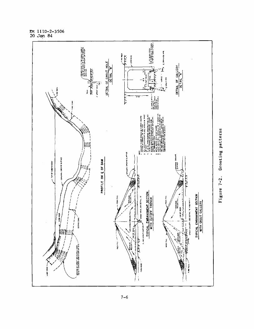
EM 1110-2-350620 Jan 84
EM 1110-2-350620 JW 84
(c) Caulk the leaks in the surface of the bedrock with wooden wedges,dry pack cement grout, oakum, burlap, or other materials.
(d) Pump a thick grout into the hole until it surfaces and fills thefissure, then discontinue the pumping until the grout is set up sufficientlyto plug the leak. If the effectiveness of subsequent grouting in lower zonesmay be questioned because of the tendency of the previous leaks to reopen andrelieve grouting pressure, set a packer near the bottom of the previouslygrouted zone. After the final depth is grouted, grout at full pressure fromthe pipe connection at the collar of the hole.
(e) Dike the leak and allow the grout with added accelerator to set up.
(f) Add additional shallow surface holes to distribute grout at shallowdepths.
c. Grout Hole Connectors. Grouting is usually done through pipe nipplesgrouted in the tops of the holes or through packers. Where rock is too softor friable to hold them, the nipples may be embedded in concrete. If problemswith nipples breaking loose are anticipated, the specifications should containprovisions for using a packer.
d. Area/Blanket/ConsolidationGrouting. Grout holes usually less than30 feet deep on a closely spaced grid pattern are often used in the upstreamportion of the foundation or under the entire impervious core contact area.This pattern consolidates the critical upper surface and treats any unseenweak zones, and affords better protection of the core from piping. The opera-tion should be accomplished prior to curtain grouting to take advantage ofpretreatment of the upper zone.
e. Grouting Through Embankments. In new dam construction the groutcurtain should be completed prior to construction of the embankment for thefollowing reasons:
(1) Hydraulic fracturing or washing of the embankment may occur if fluidis used in drilling.
(2) Drilling with air below the piezometric surface creates high differ-ential pressures in the hole, which may result in collapse of the hole orfracturing of the embankment.
(3) Washing and pressure testing are critical because of the danger oferosion at the embankment-foundation contact.
(4) No observations canbe made as to grout travel or treatment of spe-cific critical areas.
7-7
EM 1110-2-350620 JarI84
(5) The tight pattern of holes will probably not be constructed as de-signed because of deviations during drilling.
(6) Use of high grout pressure may heave and crack the embankment.
(7) Grout traveling downstream through the foundation may affectdrainage.
(8) Grouting through an embankment invariably involves higher costs.Grouting has been done through completed dams as a remedial measure. Casingshould always be used through the embankment and grouting should only be donethrough packers.
f. Grouting Galleries and Adits. Grouting and drainage galleries arecommon in concrete dams and have been used in earth- and rock-fill dams.Adits in abutments have been used for grouting and drainage on Corps dams.Adits and galleries are constructed prior to placement of the embankment asreinforced concrete structures in bedrock or as tunnels excavated in thefoundation or the abutments. Grouting galleries have been used as an expedientto allow the embankment to be constructed and grouting to be done during, orfollowing, completion of earthwork. See figure 7-2. Some possible benefitsfrom using adits and galleries in earth- and rock-fill dams are:
(1) Construction of the embankment canbe carried out independently ofthe grouting schedule.
(2) The advantages of grouting with the additional weight imposed on thefoundation (higher grout pressures) can be realized, while most of the objec-tion to grouting through the embankment can be eliminated.
(3) Adits are also excellent exploratory tools that give detailed dataon the nature of the rock discontinuities to be treated.
(4) Galleries and adits allow access to the foundation during and afterreservoir filling so that additional grouting can be plamed and results evalu-ated from direct observations.
(5) If galleries and adits are used for drainage holes, pressure can bepartially relieved immediately downstream of the grout curtain.
(6) Galleries and adits can be used to house foundation instrumentationoutlets. Design of the gallery and impervious section of the dam must con-sider that the full reservoir head will be dissipated through the core im-mediately above the gallery.
g. Grout Caps. Concrete grout caps have been used for earth dams, par-ticularly in areas of weak or highly fractured rock, to impede surface leakageand to provide anchorage for grout connections. Grout caps are constructed as
7-8
EM 1110-2-350620 Jan 84
concrete trenches encompassing all grout lines, and are usually 3 to 6 feetdeep, but may be large and deep enough to contain a grouting gallery forfuture inspection and remedial grouting. Use of a grout cap has the followingadvantages: (1) minimizes development of surface leaks, (2) provides a level-ing course for operations, (3) trench construction ensures treatment of theupper foundation by providing a positive cutoff and added protection for theembankment, (4) creates a wider grouted area by forcing grout to travel longerhorizontal distances, (5) tends to eliminate the ungrouted upper few feet,which may be experienced with nipples, and (6) eliminates problems with set-ting nipples (if nipples are set in concrete or drilled after completion).Disadvantages include (1) masking of breakouts, (2) rock damage during excava-tion for the cap, and (3) possible uplift or cracking creating seepage pathsthrough the concrete. Caution. A grout cap will not permit a significantgrout pressure increase in the upper zone of the grout curtain, and must bestrong enough to handle loads from the placing and compacting of overlyingfill.
h. Abutment Grouting. The same applications for general grouting applyto abutment grouting. When there is a change in orientation of holes fromthose of the adjacent foundation, additional grout holes should be fanned atthe change in attitude or the segments of the curtain overlapped to ensure thecontinuity of the grout curtain. All or part of the grout curtain can be con-structed from adits, usually at a higher cost but with the same potential bene-fits as described in e above. The surface from which grouting operations areperformed can be greatly improved through use of the treatments outlined inparagraph 4-2c, of EM 1110-2-2300, before grouting.
i. Reservoir Rim Grouting. Under certain geological and prbject opera-tion conditions, leakage from the reservoir may be a problem and require treat-ment. Loss of water through narrow ridges or through karst topography couldaffect the economics and safety of the project, and the regional groundwaterconditions. The potential for these conditions should be identified duringthe exploration and design stages. Methods include mapping the reservoir, ex-ploratory holes, a detailed groundwater survey, and pump tests to determinepotential leakage. If considered necessary, rim grouting should be includedas a part of the dam contract and should be designed to reduce leakage to anacceptable level. A decision to defer rim grouting until later might be madein some instances, and would be an acceptable alternative if access is assured.Monitoring in this case should be accomplished through the use of observationwells placed strategically around the rim.
j. Blasting. Special attention should be directed to limitations onblasting after grouting. It ❑ay be necessary to monitor the blasting and es-tablish limits for each project. As a rule, grouting should be accomplishedafter all blasting in the area has been completed.
7-9

EM 1110-2-35062U J~ 84
CHAPTER 8APPLICATION TO TUNNELS, SHAPTS, AND CHAMBERS
8-1. General Applications: The areas of application covered in this chapterhave found ever-increasing uses in civil projects. Subsurface structures re-quiring isolation from water and hardening for resistance to shock frequentlyare treated by grouting.
8-2. Purposes of Grouting. The purposes of grouting tunnels, shafts, andchambers are generally to consolidate the surrounding materials and to protectthe structures from the following:
a. Water infiltration.
b. Chemical attack.
C. Shocks.
d. Instability.
e. Radiation (waste disposal).
f. Uneven load transmittal or distribution.
8-3. Applications.
a. Tunnel Treatment. Water infiltration or unstable conditions duringdriving operations or into old sections of tunnels may require pressure grout-ing. The grouting is usually accomplished using portland cement or chemicalgrouts, or combinations of both.
(1) Grout holes. Holes are oriented to best intercept known or sus-pected fissures, weak zones, and fractures in rock. Size of drilled holes mayrange from AW (48 millimeters) to NW (75.7 millimeters). A primary system ofholes is initially drilled on selected spacing. Pneumatic or mechanicalpackers are placed near the collar of the hole. Water, sometimes dyed, isused to pressure test the area being prepared for grouting. Pressure gagesare placed in-line at the hole collar and at the pump discharge head. Groutis injected and carefully monitored for take and pressures. Split-spacing maybe required to accomplish additional grout injection. Grout mixtures, pres-sures, pumping rates, depth of grout holes, and drilling and grouting sequenceof the holes are determined in the field. In flowing water conditions the useof quick-setting grouts incorporating accelerators with the possible additionof fillers, such as chopped and shredded cellophane, shredded rubber, sawdust,crushed cottonseed hulls, and high-density fines, have in some instances com-pletely sealed or reduced the flow to acceptable levels. Chemical grouts havealso been very effective due to their controlled gel time. Applications for
8-1

EM 1110-2-350620 J= 84
seepage cutoff in dam projects are describzd in paragraph 5-5, and additionaldiscussion is given in EM 1110-2-2901.
(2) Equipment. Standard drilling and grouting equipment should be ofthe electric- or air-powered type normally used for underground work. Theequipment should be sufficiently durable, compact, and light for easy trans-port. Telephonic communications are frequently necessary between the headerand grout pump.
b. Shaft Treatment. Ring grouting is normally employed to seal a perme-able, water-bearing formation or rock fissures and fractures prior to shaftsinking. The treatment is accomplished by drilling s series of angled or ver-tical holes from the perimeter of the planned shaft. Combinations of portlandcement and chemical grouts may be employed for such applications. Before thegrout is injected, pumping tests are conducted using water to indicate grouttakes as well as to ascertain a range of gel times for the chemical grouts,assuming that these grouts may be pumped as easily or nearly as easily aswater. After the primary ring of holes is grouted, a second and possibly athird ring may be required. Split spacing of holes may subsequently be neces-sary in one or more of the rings to form an adequate ring curtain. As theshaft sinking advances, additional grouting may be required from inside theshaft if the degree of permeability encountered downshaft is judged to beundesirable.
c. Liner Grouting. Liner grouting is normally undertaken following theplacement of tunnel or shaft liners, which are usually constructed of concretebut may also be constructed of steel. Grouting of the space between linersand the formations in which liners are placed is referred to as backpack grout-ing. This grouting usually requires the use of portland cement grouts. Thegrout is injected from the invert of the liner for a tumel and displacedupward. Holes drilled above the injection points provide venting as well asdetermine the progress of grouting and may later be used as injection points.Backpack grouting at the tumel crown contact area requires that pressure bemaintained until hardening of the grout occurs to ensure intimate contact ofthe grout with the crown. Expansive cement grouts are frequently used to con-tact grout crowns after the backpack grout has hardened. For shaft linings, aseries of radial holes is drilled and grouted from the inside of the shaft.Hole spacing and sequence will vary, but usually split-spaced secondary holeswill be drilled and grouted. Closely monitored low to moderate pumping pres-sures are used to inject grout behind liners.
d. Consolidation Grouting. Where excavation of a tunnel or chamber hasloosened the surrounding rock, or caused ❑inor movements prior to lining place-ment, it may be necessary to consolidate the rock and fill open joints andfractures. In these cases grout holes can be drilled through the lining tothe depth of disturbance, and grouting accomplished as described in para-graph a above.
8-2
EM 1110-2-350620 Jan 84
e. Permanent Drain Holes. Permanent drain holes are drilled to inter-cept seepage through structures to relieve uplift and hydrostatic pressures.These holes should always be drilled after the completion of all grout injec-tions conducted in a particular area. Drain holes 3 inches in diameter willbe adequate for most conditions. The spacing of drain holes can range from afew feet to as much as 20 feet. The spacing is largely based on the perme-ability of the areas to be drained, and close spacing is required for areas oflow permeability.
8-3
EM 1110-2-350620 JW 84
CHAPTER 9APPLICATION TO NAVIGATION STRUCTURES
9-1. General. Grouting for navigation structures is ordinarily performedprior to, or during, the original construction to improve the foundation orreduce seepage and uplift pressures. Remedial grouting under slabs or founda-tions may also be required after construction as well as for wall repair ap-plications, The application of foundation grouting would be similar to thatdescribed for dams in chapter 7.
9-2. Foundation Treatment. The mass strength and permeability of the soil orrock of the foundation on which the structure is founded may require precon-struction improvement or subsequent remedial work. Treatment may be requiredboth for permanent work as well as temporary structures such as cofferdams.These improvements may be achieved by using various types of applications in-volving the injection of cement or chemical grouts or both. A laboratoryevaluation of the materials planned for use in the treatment is recommended,followed by onsite injection tests and core recovery from injected areas.Structures suffering foundation erosion can be grouted with the conventionalequipment and materials frequently used in grouting large voids. Special con-sideration should be given to the ability of the grout to seek its own level,the bonding properties of the grout injected into areas of exposed piling soas not to increase the dead weight of the structure, and the rate of flow ofthe water in the area to be grouted. Parts of chapters 7 and 10 of this manualdescribe various applications for foundation improvements. EM 1110-2-3504 isa recommended reference, as well as “Consolidation Grouting at an ExistingNavigation Lock,” by Neff, Sager, and Griffiths.
9-3. Repairs. Wall, slab, apron, and foundation repair of navigation struc-tures is often necessary. Special grouting applications are frequentlyrequired.
a. Vertical Concrete Walls. Cracks may develop and horizontal and ver-tical construction joints may become highly permeable in vertical concretewalls. Grouting methods are described in EM 1110-2-2002. Natural weathering,mainly freezing and thawing, often results in cracking and spalling; bargetraffic through locks also generally results in severe abrasion not only inthe upper section of guide walls but also of the main lock walls. Repairs maybe made by injecting water-insensitive epoxies. Repair of large cracks may beaccomplished by using fine, dry sands as a filler in epoxies. Spalled areaslocated on vertical walls often require forms to retain either a portland ce-ment grout or an epoxy/sand grout. Special epoxies are formulated for use inmuch patching work. As a result of advanced epoxy technology, a great varietyof epoxies are available for specific job requirements, such as infectivityinto dry or wet cracks and band of old concrete or grout to new grout. Amethod of repairing areas severely abraded by barge traffic involves placingsteel armor plates over the abraded areas by anchor bolting, sealing the bot-tom and end edges by caulking, and injecting portland cement grout through
9-1

EM 1110-2-350620 Jan 84
grouting nipples that are located near the bottom of the armor plate. Thisgrouting operation is conducted in compartmentalized sections provided betweenthe armor plate and the concrete face. For additional information on verticalwall repairs, refer to WES TR C-78-4 and WES Translation No. 65-4 (app A).
b. Slab and Apron Crack Repair. Repair for navigation structures is con-ducted using epoxies and portland cement grout applications. The WES publica-tion, “Maintenance and Repair Practices for Pavements, Facilities Engineers,”is a recommended reference.
c. Filling voids under slabs and aprons and stabilizing and jackingslabs are covered in paragraph 11-3d and e.
9-4. Grout Curtain Through the Lock Area. Conditions in the foundation oflocks will in many cases require the placement of a grout curtain. The methodof placement of such curtains is generally the same as that for curtainsplaced in the foundations of concrete dams. The emplacement of these curtainsis described in detail in paragraph 7-1. The grouts used in these curtainsmay be either portland cement, chemical, or both.
9-2
EM 1110-2-350620 Jan 84
CHAPTER 10APPLICATION TO BUILDING FOUNDATIONS
10-1. General. All buildings, regardless of type and design, must be foundedon and supported by competent soil or rock or the foundation must be modifiedto assure adequate support. Foundations may be in need of improvement forvarious reasons: e.g., to increase their strength or rigidity, to prevent theerosion of subsoil by adjacent water flow, to prevent cavity formation andsoil shrinkage occurring as a result of water drawdown, to prevent subsidenceand cavities created as a result of solution charnels in underlying limestone,to prevent unbalanced soil pressure conditions resulting from differences inelevations, and to prevent the erratic behavior of soft clays subject to chang-ing moisture conditions. This chapter is devoted to grouting of buildingfoundations which have been found to be in need of improvement.
10-2. Pregrouting Investigation.
a. Physical and Mechanical Properties. The physical and mechanicalproperties of foundations must be thoroughly investigated and well definedduring the planning of grouting treatments.
b. Field and Laboratory Testing. Investigations are normally conductedunder the direction and supervision of the foundation engineer responsible forthe design and construction of the foundation for the building. The majorfield tests may include standard penetration tests, visual classification ofsoils, grouting tests, geophysical explorations, and groundwater monitoring.Laboratory tests will normally include classification, moisture content,density, void ratio, chemical analysis of water, and strength tests.
10-3. Soil Stabilization. A number of treatment methods have been success-fully used to stabilize soil. Soil-cement and soil-asphalt ❑ixtures areproven methods; however, their uses are limited to surface treatments. Intru-sion grouting consists of mixing in-place soil and grout to form low strengthsoil-grout cylindrical piles. Compaction grouting consists of using verystiff consistency grout mixtures which, under closely controlled pressures,compact the soil by displacement. The grout remains a distinct mass in closecontact with the compacted soil.
a. Intrusion Grouting. This type of grouting consists of mixingin-place soil and cement grout to form soil-grout cylindrical piles. Thisprocedure requires specialized equipment which consists of a hollow tube withvanes at the lower end. These vanes are rotated slowly while being forcedinto the soil. This process permits either cement grout or chemical admix-tures to be introduce~ throug~form a piling system.
b. Compaction Grouting.using stiff consistency cement
the tube for subsequent mixing with the soil to
This method ofgrout mixtures
soil stabilization consists ofwhich are pumped to subswface
1o-1
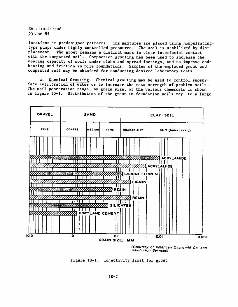
EM 1110-2-350620 Jan 84
locations in predesigned patterns. The mixtures are placed using nonpulsating-type pumps under highly controlled pressures. The soil is stabilized by dis-placement. The grout remains a distinct mass in close interracial contactwith the compacted soil. Compaction grouting has been used to increase thebearing capacity of soils under slabs and spread footings, and to improve end-earing and friction in pile foundations. Samples of the emplaced grout andcompacted soil may be obtained for conducting desired laboratory tests.
c. Chemical Grouting. Chemical grouting may be used to control subsur-face infiltration of water or to increase the mass strength of problem soils.The soil penetration range, by grain size, of the various chemicals is shownin figure 10-1. Distribution of the grout in foundation soils may, to a large
# I .U 0.01 0.001GRAIN S::E, MM ‘
(Courtesy of American Cyanamid Co. andHalliburton Services)
Figure 10-1. Infectivity limit for grout
10-2
EM 1110-2-350620 Jan 84
extent, be controlled by adjustment of the gel times. Generally, chemicalgrouts are considerably more expensive than the asphalt, cement, or claygrouts. Chemical grouting should be considered for those applications wheretheir use is warranted to obtain desired results and when it is economicallyjustified. Postgrouting field and laboratory testing programs should be con-ducted to determine the adequacy of the chemically grouted soil to support thefoundation of the planned structures. (EM 1110-2-3504, and “Soils Engineering,”R. H. Karol (app A).)
10-4. Rock Foundations. Grouting of rock foundations for buildings may bedesirable in cases where the foundation rock is solutioned limestone, where itis highly fractured and broken, or where it contains open joints. The grout-ing will not only consolidate the rock and add to the bearing strength, butwill aid in preventing piping of soils into the rock fractures and cavities.Grouting may also be used in jointed rock to consolidate the rock prior toblasting and excavating where close tolerances in excavation limits arerequired.
10-3
PRECISIONC~TER 11
AND SPECIALTY
EM 1110-2-350620 Jan 84
GROUTING
11-1. General Statement. Precision ~routinQ mav be defined as the Dlacementof a special type of grout in a well-~efined-are~ under a highly con~rolledapplication to meet rigid job requirements. Specialty grouting may be definedas those applications that deviate from conventional techniques. Precisionand specialty grouting operations require careful selection of grout mixturesand thorough planning. Thesigned such grouting tasks.
11-2. *“ Grouting cansion and specialty grouting
most experienced grouting personnel should be as-
be used in a variety of unique situations. Preci-may require only small amounts of grout, but the
outcome may be very significant.
a. This chapter is applicable in part to concrete structures; conse-quently, grouting techniques, ❑ixtures, materials, and equipment normallyutilized for concrete repair can be used on these structures. EM 1110-2-2002is a comprehensive manual covering many different types of materials, equip-ment, and repair techniques. This manual not only discusses the use of port-land cement grouts, but also concrete, asphalt, shotcrete, drypack, preplacedaggregate concrete, epoxy resins, protective surface coatings, and jointsealers used in repair work. The manual also contains discussion of crackrepair, major repairs, and surface repairs.
b. Civil projects that may include grouting as a part of original con-struction or for repair include highways, surfaces and underground powerhouses,large buildings, and flood control structures. Grouting may be required forrepairing and/or strengthening any of the structures listed as a method ofsatisfying immediate and long-range project needs.
11-3. Applications.
a. Tendon Grouting. The purposes of this type of precision grouting areto provide protection to the steel tendons as well as to provide good bond be-tween the tendons and the ducts, thereby improving the durability and load-carrying capacity of the structural member. Mixtures used in tendon groutingshould contain materials that provide protection of tendons from corrosion andare virtually free of components such as chlorides and sulfides that promotestress corrosion of tensioned steel tendons. The mixture should exhibitlittle or no bleeding and should be shrinkage compensating. The mixtureshould be easily pumped and free of fine aggregate to ensure maximum penetra-tion into small spaces between tendon strands. The grout should have pro-longed pumpability time to provide for recirculation during injection. Admix-tures should be used that contain water-reducing agents, controlled expansionadditives, and dispersant agents and that produce a grout that is thixotropicfor a limited time, shrinkageopment when added to portland
compensating, dense, and high in strength devel-cement ❑ixtures. Mixtures used for injection
11-1
EM 1110-2-350620 J~ 84
into tendon ducts should have high fluidity. Mixing equipment preferablyshould be of the continuous colloidal or high speed shearing type, and thepositive displacement, nonpulsating type of pump should be used for injection.
b. Machine Base Grouting. Civil projects sometimes include the groutingof extremely large steel plates that form the bearing base plates for genera-tors, turbines, roller mills, compressors, rails, column plates, and a varietyof production-type heavy machinery. The machine base plates are usually posi-tioned over concrete foundations and fixed by anchor bolts. Shims are used tolevel base plates, usually leaving 1 to 3 inches between the plate and con-crete foundation to be grouted. The space is formed on all sides to containthe grout, which is either poured or pumped beneath the plate from one sideonly to minimize possible entrapment of air. The grout placement is best ac-complished in one continuous operation. The selection of mixtures for useunder machine bases and similar placements is described in CRD-C 621 (app A).For very high strength grouts, additives such as silica fume may be consideredafter appropriate laboratory testing.
c. Rock Bolt Grouting. There are ❑any types of rock bolt anchoring sys-tems. EM 1110-1-2907 includes information on how to install and grout rockbolts.
d. Slab Stabilization. Slab stabilization is a method that utilizesgrout to fill voids beneath concrete slabs to minimize impact loading damage,~orrect faulty drainage, and prevent pumping at transvers~ joints and con--traction cracks. A variety of grout mixtures and mud-cement slurries are usedto accomplish this. The WES publication, “Maintenance and Repair Practicesfor Pavements, Facilities Engineer,” contains useful and detailed informationon slab stabilization.
(1) Grout mixtures composed of finely graded, clean sand and cement,with admixtures if needed, provide long-term stability beneath slabs, and haverecently been replacing mud-cement slurries.
(2) Mud-cement slurries tend to develop very little strength and canshrink, and prove to be unstable in wet conditions. Slab stabilization isusually conducted while old slabs are being prepared for resurfacing. Majoritems of equipment required are a core drill; a concrete or pug-type mortarmixer; a positive displacement, nonpulsating type grout pump; and associatedequipment and accessories.
e. Slab Jacking. Slab jacking is actually an extension of slab stabili-zation; however, the application is somewhat more involved. Slab jacking maybe described as a quick and economical method of raising a settled section toa desired elevation by pressure injecting cement grout or mud-cement mixturesunder the slabs.
(1) Purpose. The purpose of slab jacking is to (a) improve the riding
11-2
EM 1110-2-3506
20 Jan 84
qualities of the surface of the pavement, (b) prevent impact loading over theirregularities by fast-moving traffic, (c) correct faulty drainage, (d) pre-vent pumping at transverse joints, (e) lift or level other structures, and (f)prevent additional settlement.
(2) Mixtures. A grout mixture consisting of a finely graded, clean sandand cement, having approximately 20 percent cement and well-graded, clean,fine sand with about 30 percent or more fines passing the No. 200 sieve, canbe easily pumped and will develop adequate strength. The water content ofsuch a mixture must be one to produce a low-viscosity consistency, yet havesufficient viscosity to maintain the sand in suspension. In the case of mix-tures composed only of sand, cement, and water, various types of admixturesmay be added to the mixture to either accelerate, retard, or expand the grout;however, such additives should be used with extreme care and their effect onthe grout studied by testing in the laboratory prior to use in the field.
(3) Equipment. The minimum major items of equipment normally requiredto conduct a slab jacking operation efficiently are stated in d(2) above.
(4) Application.
(a) Extreme care must be exercised during slab jacking operations to pre-vent pyramiding of the grout under the slab in the immediate vicinity of theinjection hole. The grout should raise the slab slowly and with uniform pres-sure. To accomplish this, an array of holes must be drilled through the slabin a pattern that will permit the lateral flow of grout to penetrate all areasunder the slab, and the jacking rate should be slow enough to permit the groutto fill all existing voids properly and completely. Only general rules can beused in determining the location of holes for grout injection. The operatorlearns to space holes according to the particular job at hand. Holes gener-ally should not be placed closer than 18 inches to edges or joints. Theyshould be at locations spaced not more than 6 feet on center so that approxi-mately 25 to 30 square feet of slab is raised by pumping any one hole. Exces-sive pumping in any one location may result in cracking of the slab. A closerspacing arrangement of the holes will be required if the slab cracks. Addi-tional holes may occasionally be required to fill voids that have no communi-cation with each other. The diameter of the holes should be 1-1/4 to1-1/2 inches.
(b) If the grout is pumped too quickly, the slab may be cracked bypyra-miding. A thick slurry grout should be used initially for slab lifting. Athick grout should not be pumped at rates exceeding 1 cubic foot per minute.The pumping rate for low viscosity and thin grouts may be increased to as muchas 3 cubic feet per minute.
(c) When jacking is done from one hole, the grout injection should con-tinue until the grout appears in adjacent holes or the slab is raised to theproper grade. Adjacent holes may temporarily be sealed with wooden plugs,
11-3
EM 1110-2-350620 Jan 84
.
which can readily be removed following the setting of the grout. When thegrout nozzle is removed following the completion of slab jacking operations,all holes should be cleaned and filled with a stiff 1:3 cement-to-sand mortarmixture, which is tamped into place and floated to a smooth finish.
(d) Application of the slab jacking method must be carried out by com-petent, experienced crews. A slab-jacking crew generally consists of from 6to 10 people.
f. Lost Circulation Grouting. During the drilling of boreholes, drill-ing fluid circulation may be lost to a highly fractured zone or a weak orporous formation. In the event of lost circulation, materials may be added tobasic portland cement grout mixtures to block, bridge, or seal the openings inthe formation. The lost circulation materials most commonly used includesands of various types and gradations, cellophane flakes of controlled sizes,ground plastic, shredded rubber, and crushed cottonseed hulls. These mate-rials may be added to the cement slurry individually or in combinations; thelatter rarely exceeds two ❑aterials.
g. Preplaced Aggregate Grouting. Preplaced aggregate grouting involvesthe placement of a selected type and gradation of a coarse aggregate in formsor cavities and the injection of a sanded or unsanded portland cement groutinto the mass to fill the voids. This method is sometimes used for construct-ing “cast in place” piles, and for providing roof support for abandoned mines.Useful information in planning preplaced aggregate grouting is discussed inWES Technical Memorandum 6-380.
h. Postplaced Aggregate Grouting. The placement of grout into forms orcavities prior to the placement of the aggregate is a quick and economicalapplication. The grout ❑ixtures can also be proportioned with a lower watercontent since pumping into injection pipes is not necessary. The grout isinitially introduced into the placement area and is followed by the placementof the aggregate by clamshell, end loader, or other means. Maintaining agrout level above aggregate placement is important at all times except when“topping off” nears. Means should be provided to finish and cure the surface.
i. Foam Slurry Grouting. The constituents that compose foam slurriesand a range of physical properties are briefly described in paragraph 5-2c.Mixing and pumping systems generally consist of in-line metering foam genera-tors or transit mix trucks, tub mixers, and ribbon blenders. A measured amountof foam is introduced into a measured amount of cement slurry for homogeneousmixing. The advancing cavitation-type pump is best suited for pumping foamgrout. Injection lines four or five inches in diameter have been found to besatisfactory for the placement of foamed slurry grouts.
j. Saltwater Grouting. Saltwater grouting is conducted during the sink-ing and driving of shafts and tunnels in salt formations and behind boreholecasings that either terminate in cavities excavated into salt domes, or pass
11-4
EM 1110-2-350620 Jan 84
through salt formations for various purposes. Grouts developed for possibleuse in waste isolation in salt formations require extensive developmental workin providing a grout having a durability of extremely long life. The groutmixture used should contain approximately 3 pounds of soduim chloride (NaCl)in solution per gallon of mixture water to provide a brined, saturated mixturewater that will prevent dissolution of rock salt and contact faces. Amountsof salt in excess of approximately 3 pounds per gallon tend to retard portlandcement mixtures, whereas amounts less than 3 pounds per gallon may result in adegree of acceleration of the set. Salt-saturated mixture water should alsobe considered in grouts proposed for use in saline environments. Attapulgiteclay is used in lieu of bentonite in salt grouts.
k. High-Density Grout Placements. Structures constructed for nuclearand high-energy laser research and hazardous waste storage frequently requirehigh-density walls, ceilings, and floors. Such construction may be accom-plished by using the preplaced aggregate method; magnetite or ilmenite coarseand fine aggregates or other types of high-density aggregates are substitutedfor the conventional types of aggregates normally used. Particular attention❑ust be given to forming, which must be designed to support heavy loads and tobe essentially watertight.
1. Grouting Waste Disposal Wells. Extremely high durability groutsshould be developed for use in plugging hazardous waste disposal wells. Thisapplication requires portland cement grouts that are expansive, impermeable,and highly resistant to chemical attack. A waste disposal well may be pluggedwith grout by means of conventional oil well cementing equipment or similargrouting systems. The grout may be placed in a single stage or a number ofstages through the use of the drill stem and the draw-works of the drill rig.A variety of downhole tools are available for such operations, Extensivequality assurance is needed in this type of application.
m. Pile Jacketing. Bridge and causeway pilings frequently suffer exten-sive deterioration as a result of water erosiontion and growth.
, scouring, and marine infesta-An economical and expedient method of repairing these pilings
is encasement of the pilings in a protective jacket of grout. The jackets nor-mally consist of baglike nylon forms placed around steel reinforcing mesh thathas been attached to the damaged area of the steel, concrete, or wooden pilingto be jacketed. The nylon form is then filled with the grout. The grout mix-ture is normally proportioned using a sand filler and a grout fluidifier andmay contain Type III high early-strength cement when conditions ❑ay requireearly setting and strength development. This application, using conventionalportland cement grouting equipment, may be made both under and above water.
n. Grouting for Powerhouses and Deep-Buried Structures. Powerhouses,both above and below the surface, and deep-buried structures may requiregrouting. Void areas in the surrounding soil or rock adjacent to powerhousesor deep-buried structures can be grouted with well-designed grout mixtures tofurther enhance the stability and durability of the structures.
11-5
EM 1110-2-350620 Jan 84
0. Riprap Grouting. The stabilization of riprap placements may be im-proved by grouting the unconsolidated riprap. Riprap grouting may be accom-plished above and below water in providing slope protection for revetments,shoreline stabilization, levee facing, and similar projects. Riprap groutingapplications normally consist of the gravity or pump placement of fluid sanded-cement grouts into the voids existing in riprap. The mixtures may contain upto 3 to 4 parts of sand by weight of the cement. For the steeper slopes, moreviscous grout is required. The grout is usually filled to approximately 1/2to 3/4 of the depth of the voids and, where possible, topped out by broomingand cured by conventional methods.
11-6

EM 1110-2-350620 Jan 84
CHAPTER 12PERFORMANCE OF WORK
12-1. General Considerations. Grouting may be part of a general constructioncontract or may be performed by separate individual contract. Grouting pro-grams may also be accomplished by hired labor and Government-owned equipment.The type of procedure to employ is dependent upon the project complexity andcompletion schedule, existing economic conditions, technical and manpower con-siderations, organizational structure, and workload.
12-2. Contracts.
a. General Contract.
(1) Performing a grouting program under the general construction con-tract eliminates contractual difficulties that might arise from interferencebetween these operations and other construction activities. Furthermore, thegeneral contractor electing to perform the work with his own organization canuse his personnel for other job operations when the drilling and grouting workis slack. The costs for shop facilities, power, general supplies, transporta-tion, and administration will normally be less if the work is done by the gen-eral contractor rather than by separate contract.
(2) Most general contractors, however, do not have grouting equipment,and the grouting is sublet to subcontractors specializing in this type of work.A disadvantage to this type of contract is that, contractually, the Contract-ing Officer’s Representative (COR) is removed from the subcontractor (i.e.,the COR is not coordinating with the subcontractor) actually performing thegrouting and it makes it more difficult to administer and maintain control ofthe grouting operation.
b. Separate Contract. Accomplishing a grouting program under a separatecontract allows the grouting specialist to be the prime contractor, but mayprovide a situation whereby one contractor may interfere with the operationsof another, if the grouting operations are scheduled to be done concurrentlywith other contract work. For a dam project, large amounts of excavation maybe required prior to the grouting. However, if close coordination and coopera-tion are maintained with the contractors when the sequence of constructionoperations is being planned, an efficient separate contract grouting programmay be developed.
12-3. Hired Labor. The use of hired labor to accomplish the grouting programprovides greater flexibility of operations and quicker response in emergencysituations than can normally be obtained by contract. This is an importantconsideration in such work where the extent of treatment and the proceduresemployed are contingent upon the conditions encountered as the work progresses.Other advantages of performing the work with hired labor are:
12-1
EM 1110-2-350620 Jan 84
a. The Government-owned equipment is available for use on otherprojects.
b. The qualifications of the workmen are known.
c. More positive control of the work can be maintained.
12-2
EM 1110-2-350620 J~ 84
CHAPTER 13FIELD PROCEDURES
13-1. General Considerations.
a. Regardless of the number of exploratory borings or other preconstruc-tion investigations, information on the size and continuity of groutable,natural openings in rock below the surface will be relatively meager at thestart of grouting operations. The presence of groutable voids can be ascer-tained before grouting and can be verified by grouting, but the sizes, shapes,and interconnect;.onsof the voids will be largely conjectural. The art ofgrouting consists mainly of being able to satisfactorily treat these rela-tively unknown subsurface conditions without direct observations. One of thebenefits of most grouting programs is exploration. A carefully monitored andanalyzed drilling and grouting program can provide significant informationabout a foundation. It cannot be stressed too strongly, however, that thedata gathered must be correlated and analyzed to be of any benefit. The dis-cussions of grouting practices in this manual are intended as a guide, but arenot expected to replace experience,
b. Grouting procedures depend on the job, policy, objective, geology,contractor, field personnel, and individual judgment and preference. Pro-cedures subject to variations depending on field technique include drilling,washing, pressure testing, selection and adjustment of mixes, changing grout-ing pressures, flushing the holes and washing the pump system ’duringgrouting,use of delays, intermittent grouting, determining the need for additionalgrout holes, treatment of surface leaks, and maintaining up-to-date records ofdrilling, grouting, and monitoring.
c. Local adjustments of the angles, orientation, and spacing of groutholes should be made as necessary. New holes should be required as replace-ments for holes that are prematurely plugged. When adjustments to contractrequirements are ❑ade, the designers should participate in the decision. Theadjustments may include changing the spacing of primary holes, changing theangles and orientation of grout holes, or increasing or decreasing the grout-ing program.
d. Regardless of how well conceived and designed the grouting programis, the success of the program depends upon the field techniques used and upongood judgment by field personnel. Grouting techniques may not be subject tocontractor quality control and should be directed by the Corps field person-nel. For this reason, an experienced geologist should be in charge of thegrouting prpgram and he should be provided with an adequate staff.
13-2. Drilling Operation.
a. Since drilling is a vital and costly part of the foundation groutingprogram a record of all pertinent data should be kept by the inspector during
13-1

EM 1110-2-350620 J= 84
drilling operations. Entries in chronological order should be made in fieldbooks and should include all data of interest that would assist in the identi-fication of the physical characteristics of the formation examined and wouldaccount for all time spent in drilling. A sample core hole log sheet is shownin figure 15-5. A form for this purpose should be provided for the inspectorto enter data as the work progresses. Identification of material encounteredand other pertinent remarks of a geologist assigned to the project should alsobe included in the log. The following general information should be recorded-
(1) The hole number.
(2) Drilling time schedule.
(3) Names of drillers and inspectors.
(4) Size of hole and inclination.
(5) Stations or coordinates of hole.
(6) Type and identification number of bit used, and make of drillingrig.
(7) Elevations of start and of completion of drilling.
(8) Location and cause of core losses, such as open joints or beddingplanes, blocking of bit, grinding of intensely fractured rock, soft material,and gouge.
(9) Results of pressure tests.
(10) Location and nature of filled or open cavities.
(11) Sections of hole cemented, reasons for doing so, quantity of cementused, and water-cement ratio.
(12) Water table data at beginning and end of run and specific zones ofwater loss and gain.
b. Comments in regard to obtaining and recording data about drill mani-festations for respective columns in the log sheet are as follows:
(1) An attempt should be made to trap the return water in a vessel ofsome kind and measure the amount recovered during one minute. Record meterreading on water supply line over short time intervals to determine rate atwhich water is pumped through the tool string. The color of the water shouldbe recorded at intervals and at changes throughout the run.
13-2

EM 1110-2-350620 J* 84
(2) The drilling speed should be recorded as the penetration rate, i.e,the time taken to drill a run.
(3) The action of the drill rig, such as jerky, smooth, rough, or steady,should be recorded showing the limits of such action. Particular attentionshould be paid to the driller, as he may be drilling at a speed too fast toget a core or he may be drilling at a slow rate and wearing out soft material.The drill pressure should be recorded here.
(4) The driller’s log column should show the driller’s interpretation ofthe nature of the formation encountered as drilling progresses. The inspectorshould obtain the driller’s opinion without coaching or any discussion thatmight influence his statement regarding the matter. If the inspector dis-agrees with the driller, the reasons for doing so should be stated in the re-port but nothing should be said to change the views of the driller.
c. Non-Cored Holes: In holes drilled with percussion, plug, or othernon-coring bits, much of the data from drilling must be obtained from examina-tion of the drill cuttings and fluid. Valuable information can be gathered bycorrelating the drill action, color of drill water, and description of thecuttings.
d. It will be desirable to have the inspector turn in a transcript ofhis records at the end of each shift or hole drilled. The filled out formsand the core boxes will ordinarily be turned over to a geologist to completethe analysis and make up the final log sheet.
13-3. Grouting Operations.
a. Washing Holes.
(1) Washing of grout holes immediately prior to the injection of groutis necessary to a grouting program. The purposes of the washing are to removeall drill cuttings and mud from the grout holes and to flush cuttings, sand,clay, and silt from the fractures in the rock. These materials must be re-moved to the maximum extent possible so that the grout can be injected and sothat windows may not later be eroded in the grout curtain by the removal ofsilt and clay left in place in rock fractures at the time of the groutinjection.
(2) Open hole washing is normally done by inserting a small-diameterwash pipe to the bottom of the hole and injecting a jet of water, sometimes incombination with air, to wash out any material in the hole. This process ismandatory in percussion-drilled holes. There will be instances with rotary-drilled holes where it may be determined that the hole is sufficiently cleanedby washing through the drill rods for several minutes after drilling of thehole isopen to
complete. In anyits maximum depth
event, it is essential to verify that the holeand free of any obstructions just prior to an
13-3
is
EM 1110-2-350620 Jan 84
injection of grout. This ❑ay be done by measuringtape measure. An obstructed hole should be washedinjection.
hole depth with a weightedagain prior to grout
(3) After the open hole washing is completed, it is then necessary topressure wash the rock formation. The rock formation is washed either througha packer or a sealed comection at the collar of the hole. All adjacent groutholes are opened prior to the pressure washing to serve as exit points for thewater injected into the hole being pressure washed. Water and, in rare cases,air under pressure are injected into the hole. The washing should be con-tinued as long as the rate of water taken continues to increase or as long asmuddy water vents from adjacent holes or surface leaks. Air injected in shortbursts into the water is a method used to create turbulence and enhance theerosive action of the water. Air should only be used with extreme caution, incompetent rock. Reversing the direction of washing may also be helpful. Re-verse washing will ❑ake reconnection to the original hole and washing out ofthe hole necessary for a few minutes prior to grout injection. It is impor-tant to be constantly aware that excessive pressure can damage the foundationsand previously placed grout. Water pressure and air pressure should not ex-ceed the allowable grouting pressure during pressure washing.
b. Pressure Testing.
(1) Pressure testing is performed as part of the pressure washing opera-tion. Its purposes are to obtain an indication of the permeability of thefoundation, to determine the location of permeable zones, to verify seating ofthe packer for pressure washing, and to evaluate the effectiveness of thepressure washing. Adjacent holes are uncapped during the test to allow vent-ing of the water. Each grout hole must be pressure tested.
(2) The test should be initiated prior to pressure washing by injectingonly water into the hole for a ❑inimum of 10 ❑inutes under a steady pressure.The rate of inflow should be ❑easured each minute. After 10 minutes, and ifthe test indicates that passages in the formation are being opened by thewater, pressure washing should be initiated.
(3) After the pressure washing is completed, the pressure test shouldagain be performed for 10 minutes. Records of the before and after pressuretests should be kept and included in the Foundation Report.
(4) The allowable grouting pressure must not be exceeded during pressuretesting. Constant supervision must be maintained before and during the pres-sure testing and pressure washing operations.
c. The grouting equipment should generally be arranged to provide a con-tinuous circulation of grout throughout the system and to permit accuratepressure control regardless of how small the take ❑ightequipment and lines should be prevented by periodically
13-4
be. Fouling of theflushing the system
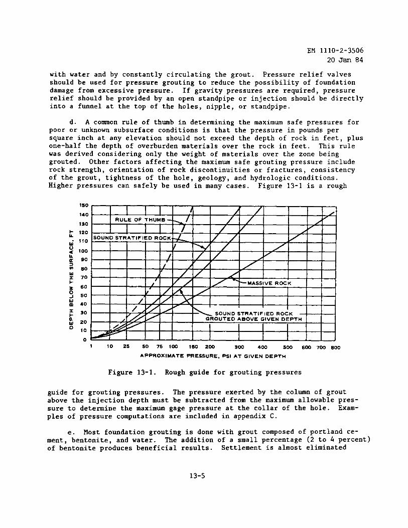
EM 1110-2-3506
20 Jan 84
with water and by constantly circulating the grout. Pressure relief valvesshould be used for pressure grouting to reduce the possibility of foundationdamage from excessive pressure. If gravity pressures are required, pressurerelief should be provided by an open standpipe or injection should be directlyinto a funnel at the top of the holes, nipple, or standpipe.
d. A common rule of thumb in determining the maximum safe pressures forpoor or unknown subsurface conditions is that the pressure in pounds persquare inch at any elevation should not exceed the depth of rock in feet, plusone-half the depth of overburden materials over the rock in feet. This rulewas derived considering only the weight of materials over the zone beinggrouted. Other factors affecting the maximum safe grouting pressure includerock strength, orientation of rock discontinuities or fractures, consistencyof the grout, tightness of the hole, geology, and hydrologic conditions.Higher pressures can safely be used in many cases. Figure 13-1 is a rough
1so
140
130
~ 120
~- 110
0< 100La 90>m 80ux 701-% 600J 50
I I I IRULE OF THUMB- \/
1/
1 1 I I / ySOUND STRATIFIED ROCK.
I !
/ 1/ / ‘
I r/{
A
‘MASSIVE ROCK
40 I
30 SOUND STRATIFIED ROCK
20GROUTED ABOVE GIVEN DEPTH
10
01 10 2s so 75 100 1s0 200 300 400 Soo 6m 700 800
APPROXIMATE PRE6SURE, PSl AT GIVEN DEPTH
Figure 13-1. Rough guide for grouting pressures
guide for grouting pressures. The pressure exerted by the column of groutabove the injection depth must be subtracted from the maximum allowable pres-sure to determine the maximum gage pressure at the collar of the hole. Exam-ples of pressure computations are included in appendix C.
e. Most foundation grouting is done with grout composed of portland ce-ment, bentonite, and water. The addition of a small percentage (2 to 4 percent)of bentonite produces beneficial results. Settlement is almost eliminated
13-5
EM 1110-2-350620 JarI84
without a significant reduction in strength or an increase in setting time.The grout is essentially nonshrinking and much superior results are achieved.Fluidizing agents may be added to reduce the viscosity of very thick grouts orfor sanded mixes. Water-cement ratios are normally specified by volume ofwater and dry volume of cement (i.e., 1 sack of cement is considered 1 cubicfoot). Figures 5-2 and 13-2 ❑ay be used for determining the cement content ofvarious neat cement grout mixes.
f. Thin initial mixes (6:1 or thinner) are usually recommended, espe-cially if the hole is dry or pressure tests indicate slow or small takes.Some formations that are quite pervious refuse 3:1 grout very quickly but willaccept 4:1 or 5:1 grout. This justifies beginning with a thin grout even inpervious conditions. If the hole accepts a few batches of the starting mixwithout pressure buildup, thicker mixes are required; however, if the pressurebuilds up, grouting may continue with the same ❑ix until refusal. It the rateof injection decreases and the pressure rises, the mix may need to be thinned.Figures 5-3 and 5-4 are charts that ❑ay be used in thickening and thinninggrout.
g. Mixtures are usually thickened by batching a new ❑ix in the mixer anddischarging it into the sump after most of the thinner grout has been in-jected. If immediate thickening of the mix is required, the hole is shut offtemporarily and cement is added to the sump. Mixing is accomplished by agita-tion of the sump and circulation through the pump and lines.
h. If the hole accepts a few more batches of the new thickened mix with-out pressure buildup, the next thicker mix is used. The process of thickeningthe grout continues until the pressure builds up, and then injection is con-tinued. The rate of injection into the hole is slowly cut back when the pres-sure tends to rise until the hole refuses to take grout at the maximum pres-sure or meets the specified refusal criteria. As the water-cement ratio de-creases, each integer change requires more cement. For example, going from2:1 to 1:1 requires 67 percent cement. Therefore, mixes of intermediate con-sistency (e.g., 2.5, 1.5, or 1.25) are used after a consistency of 3.0 or 2.0is obtained. If extremely thin (8:1 or thinner) grouts are used, a two-integerchange is normally used when thickening the grout, i.e., 10:1 to 8:1 to 6:1.When sudden refusal and pressure buildup are experienced, premature pluggingmay have occurred. If the hole is still taking a small amount of grout, watershould be pumped into it to reopen it if possible. After the water has beeninjected, a thimer grout mix may be required. If the hole is plugged, a newhole may be required. Other causes of sudden refusal include a blocked line,packer, or hole, a collapsed hole, or filled voids.
i. Rising pressures during grouting should be controlled so that theyslowly rise in increments until the desired injection pressure is reached. Ifthe injection rate suddenly increases with a drop in pressure when grouting atthe maximum safe pressure, lifting should be suspected and appropriate precau-tion taken.
13-6
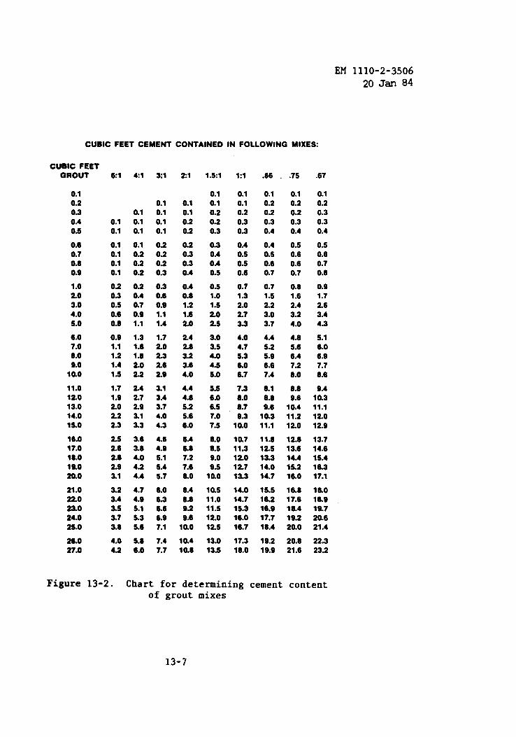
EM 1110-2-3506
20 Jan 84
CUBIC FEET CEMENT CONTAINED IN FOLLOWING MIXES:
CUBIC FEETGROUT
0.10.2030.40.6
0.60.70.80.9
1.0203.04.0S.o
6.07.06.0S.o
10.0
11.012013.014.01s.0
16.017.018.016.020.0
21.022023.024.02s.0
26.027.0
61 41 31
0.10.1 0.1
0.1 0.1 0.10.1 0.1 0.1
0.1 0.1 0.20.1 0.2 0.20.1 0.2 0.20.1 0.2 0.3
0.2 0.2 0.303 0.4 0.60.5 0.7 0.90.6 0.9 1.10.6 1.1 1.4
0.9 1.3 1.71.1 1.6 2.01.2 1.6 2.31.4 2.0 2.61.6 22 2.9
1.7 2.4 3.11.s 2.7 3.42.0 29 3.72.2 3.1 4.02.3 3.3 4.3
2S 3.6 4.62.6 3.6 4.92.6 4.0 S.12.9 4.2 S.43.1 4.4 S.7
3.2 4.7 6.03.4 4.6 6.33.5 S.1 6.63.7 S.3 6.93.6 S.6 7.1
4.0 5.6 7.44.2 6.0 7.7
21
0.10.10.20.2
0.20.30.30.4
0.40.61.21.620
242.83.23.64.0
4.44.6S.2S.66.0
6.45.67.27.6ao
6.46.60.2S.6
10.0
10.410.8
1.51
0.10.10.20.20.3
0.30.40.40.5
0.s1.01.s2.02.5
3.03.s4.04.s5.0
S.s6.06.S7.07.s
6.06.S9.09.5
10.0
10.511.011.5120125
13.013.5
1:1
0.10.10.20.30.3
0.40.s0.50.6
0.71.3202.723
4.04.7S.3S.o5.7
7.36.0279.3
10.0
10.711.312.012713.3
14.014.71S.316.016.7
17.316.0
.66 .7s
0.10.20.20.30.4
0.40.s0.60.7
0.71.52.23.03.7
4.4S.2S.96.67.4
&16.69.6
10.311.1
11.812.s13.314.014.7
1s.516.216.917.718.4
19.219.9
0.10.20.20.30.4
0.s0.60.60.7
0.61.62.43.24.0
4.6S.66.47.26.0
6.69.6
10.411.2120
12.613.614.415.216.0
16.817.616.419.220.0
20.621.6
.67
0.10.20.30.30.4
0.50.60.70.6
0.91.72.63.44.3
S.16.06.97.76.6
9.410.311.112.0129
13.714.615.416.317.1
16.016.919.720.621.4
22.323.2
Figure 13-2. Chart for determining cement contentof grout mixes
13-7

EM 1110-2-350620 JW 84
j. It is recommended that the pump system be flushed at intervals withwater when thick mixes (i.e., 2.0 or thicker) are used in the groutingprocedure. A few cubic feet of water should also be injected into the hole atthe same time.
k. A maximum pumping rate should be established for injecting grout torestrain grout travel within reasonable limits and to have better control ofthe job. Three cubic feet per minute is considered a reasonable maximum pump-ing rate for most foundation grouting. The rate of grout injection into thehole must be controlled by the Government. The maximum rate is only used whenthere is no pressure buildup. As the pressure rises, the injection rate isreduced. The rate of injection may also be reduced to restrain grout travelunder open-hole conditions. The specifications should clearly indicate thatthe rate of injection will be controlled by the Contracting Officer’s Repre-sentative and will vary from the specified refusal criteria to the maximumrate based on pressures and from 0.5 cubic foot per minute to the maximum rateregardless of pressures.
1. When pressures cannot be built up using the thickest mixes allowed,or when it is desirable to prevent grout from spreading too far, delays may beused. They may last from a few minutes to several hours. The amount of groutinjected per delay should be controlled to fulfill the intended purpose. Ifthe delays are very long and thick grout is being used, the hole and pump sys-tem should be flushed before each delay. The contractor’s efforts should alsobe allowed to be directed elsewhere during the delay. If the delays are shortand the contractor is required to stand by, provisions should be made in thecontract for payment for standby time. Delays of several hours are requiredin intermittent grouting for cavity filling. Intermediate, shorter delaysduring a single injection period may be required to build up the grout conefaster.
m. Upon the completion of grouting a hole, any grout left in the sumpshould be either wasted or thinned to the starting mix for the next hole.Grout that is not injected within 2 hours after mixing should be wasted, orsooner if the grout shows evidence of stiffening.
n. Split-spaced grout holes may be mandatory according to the contractspecifications, or may be required due to grout takes. Split-spaced holesshould normally be required on both sides of a hole that takes more grout thanthe established minimum for the job. Holes that are prematurely pluggedshould be replaced with new holes. Split-spacing criteria is discussed inpara. 13-4c.
o. Drilling and grouting should not be permitted in the same section con-currently. After grouting of a given order of holes is completed and 24 hourshas elapsed, the next order of holes may be drilled in the section as required.
P. Surveillance of the area should be made frequently during grouting tocheck for surface leaks and to collect monitoring data from other holes,
13-8
EM 1110-2-350620 J* 84
springs, piezometers, wells, and seeps. Records should be kept of any dis-colorations, changes in flow, or changes in water levels. Leaks are con-trolled, if necessary, by dikes or talking with materials such as oakum, woodwedges, or burlap. If the leaks are serious, an accelerator may be added tothe ponded grout within a diked area and a delay may be used to allow the groutto set. It the leak cannot be stopped, grouting may be continued at reducedpressure with a thicker mix. During grouting or after grouting is completedin each reach, exploratory coreholes should be drilled and pressure tested tocheck the adequacy of the grouting. These borings may indicate that condi-tions in all or parts of the formation already grouted will require additionalgrouting. In such event, the equipment must be returned and additional holesshould be drilled and grouted.
q. For winter grouting, all grout should be maintained at temperaturesabove 50°F until injected. The temperatures of mixing water should range from50° to 100°F when added to the grout mixer. Storage of grouting materialsshould be at temperatures above freezing. In addition, when grouting surfacerock, the surface temperature should be no colder than 40°F before and duringinjection and for a period of 5 days thereafter. Insulation, heated enclo-sures, and water heaters are frequently necessary.
r. In extremely hot weather, grout and grouting materials should be pro-tected from direct sunlight. It is desirable to maintain the grout at tempera-tures below 90°F. The higher temperatures not only increase water demand and,consequently, shrinkage but also accelerate the setting time of the grout,which decreases the working time.
s. Geologic sections and profiles should be kept up to date with drill-ing, testing, and grouting data, and records should be made of monitoring datato evaluate the ongoing grouting program. This information should also be in-cluded in the foundation report for future reference.
t. Evaluation of grouting effectiveness must be constant and continuousduring the program. It should be a joint effort between engineering and con-struction personnel. If problems develop, reaction should be expeditious.Flexibility must be maintained for making changes and improvements as the pro-gram progresses. Design changes of other project features are sometimes madebased on knowledge of foundation conditions gained during grouting.
13-4. Completion of Grouting.
a. Grouting may be continued to absolute refusal at the maximum groutingpressure, although this is not usually done. There are two methods that aremost frequently used to determine when grouting is complete. One specifiesthat grouting shall continue until the hole takes no grout at three-fourths ofthe maximum grouting pressure. The other requires that grouting continueuntil the hole takes grout at the rate of 1 cubic foot or less in 10 minutesmeasured over at least a 5-minute period. This is often modified according to
13-9
EM 1110-2-350620 Jan 84
the mix and/or pressure used. The second specification is more readily corre-lated with pressure test results than the first.
b. If there is doubt about the completeness of treatment in any zone orarea, a check hole or holes should be drilled. Such holes can be drilled torecover core for examination, or they may be drilled for study by the boreholecamera or television camera. However, a quicker and less expensive check canbe ❑ade by drilling and pressure testing another grout hole. If tight whenpressure tested with water, the rock is satisfactorily grouted; if the holetakes water, additional grouting is indicated. 1
c. The process of split-spacing should continue as long as there issignificant reduction in take with each new series of split-spaced holes,or until takes are not considered to be significant for the particularproject.
13-10
EM 1110-2-350620 JarI84
CHAPTER 14METHODS OF ESTIMATING
14-1. General Considerations. The work involved in a drilling and groutingprogram can only be approximated in advance of construction. Quantities areestimated for bidding purposes, but substantial variations are common. Thecontract specifications and bid items should be prepared so that the estimatedquantities for each of the bid items may vary substantially without affectingunit prices. However, a concerted effort must be made to estimate the quantityof drilling and of grouting materials (e.g., grout take) that will be required.
14-2. Test Grouting. For medium and large projects, probably the most re-
liable method for estimating grout take is to conduct a test grouting programas discussed in paragraph 3-5. The -sitechosen for testing should be geo-logically characteristic of what was found during subsurface exploration.
14-30 Grouting Records. A less reliable method for estimating quantities ofgrouting materials is to refer to grouting records from sites located in areasthat have similar geology and rock types. This method will give a generalfeel for the quantities; however, it will require extensive experience andknowledge of grouting on the part of the estimator to extrapolate the data toanother site. A major problem in utilizing this method is the possibility ofdiffering approaches or philosophies of the people doing the grouting. Indi-vidual grout specialists working in similar environments may place consider-ably different quantities of grout, according to their various techniques, buta satisfactory grout job can be achieved in each case.
14-4. Evaluation of Exploration Borings. The evaluation of the cores fromthe exploration program, as well as the results of the water pressure tests,is fundamental in the initial stages of preparing a grouting estimate. Utiliz-ing this method alone for estimating would be unreliable since it has beenproven that rock formations which take water during pressure testing fre-quently do not take grout.
14-5. “Unit Take” Estimates. A method frequently used during preparation ofdetailed estimates for drilling and grouting programs is called the “unit take”method. In the procedure used for this method the area to be grouted is di-vided into horizontal reaches and vertical zones of varying permeability,based on site geology and pressure test results. Estimates are made of thenumber of primary and split-spaced holes required to complete each area andzone. Grout take in cubic feet per foot of grout hole is assigned, as well asthe reduction in grout take for each split and zone. The amount of grout takein each series of split-spaced holes normally would be less than the precedingset of holes, and in multiple lines, take in each line less than a previouslygrouted line. Unless geologic conditions indicate otherwise, the unit takewould normally decrease with depth. Each zone of each hole is assigned an es-timated take in cubic feet of grout per linear foot of grout hole. A typicalestimate using this method may look like the following:
14-1
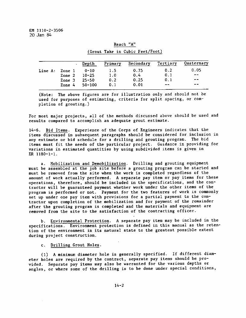
EM 1110-2-350620Jan 84
Reach “A”
(Grout Take in Cubic Feet/Foot)
Depth Primary Secondary Tertiary Quaternary
Line A: Zone 1 0-1o 1.5 0.75 0.2 0.05Zone 2 10-25 1.0 0.4 0.1 --
Zone 3 25-50 0.2 0.25 0.1 --
Zone 4 50-100 0.1 0.01 -- --
(Note: The above figures are for illustration only and should not beused for purposes of estimating, criteria for split spacing, or com-pletion of grouting.)
For most major projects, all of the methods discussed above should be used andresults compared to accomplish an adequate grout estimate.
14-6. Bid Items. Experience of the Corps of Engineers indicates that theitems discussed in subsequent paragraphs should be considered for inclusion inany estimate or bid schedule for a drilling and grouting program. The biditems must fit the needs of the particular project. Guidance in providing forvariations in estimated quantities by using subdivided items is given inER 1180-1-1.
a. Mobilization and Demobilization. Drilling and grouting equipmentmust be assembled at the job site before a grouting program can be started andmust be removed from the site when the work is completed regardless of theamount of work actually performed. A separate pay item or pay,items for theseoperations, therefore, should be included in the specifications, and the con-tractor will be guaranteed payment whether work under the other items of theprogram is performed or not. Payment for the two features of work is commonlyset up under one pay item with provisions for a partial payment to the con-tractor upon completion of the mobilization and for payment of the remainderafter the grouting program is completed and the materials and equipment areremoved from the site to the satisfaction of the contracting officer.
,b. Environmental Protection. A separate pay item may be included in the
specifications. Environment protection is defined in this manual as the reten-tion of the environment in its natural state to the greatest possible extentduring project construction.
c. Drilling Grout Holes.
(1) A minimum diameter hole is generally specified. If different diam-eter holes are required by the contract) separate pay items should be Pro-vided. Separate pay items may also be warranted for the various depths orangles, or where some of the drilling is to be done under special conditions,
14-2
EM 1110-2-350620 J= 84
such as from a gallery or tunnel. If it becomes necessary to drill the groutfrom a hole after set, through no fault of the contractor, a special paymentprovision for redrilling should be provided. This is usually specified asone-half of the cost of initially drilling the grout hole.
(2) The contract drawings and specifications should clearly indicate thedirection, maximum angle, maximum depths, and allowable deviation therefrom.
(3) The amount of drilling should be estimated on the basis of the jobas planned and shown on the drawings. The amount of drilling anticipated foreach drilling item should be shown.
d. Drilling Exploratory Holes. To determine the effectiveness of thegrout curtain or portions thereof during grouting operations it may be re-quired to drill exploratory holes at key locations. Drilling of exploratoryholes will be measured for payment on the basis of linear feet of holes ac-tually drilled. If a portion of exploratory or grout hole drilling is to bedone through overburden, a separate pay item should also be included for thisportion (see ~ above).
e. Pressure Washing and Pressure Testing. Preliminary washing of thegrout hole usually is included for payment as a part of the drilling opera-tions, and a separate pay item is not necessary.- Pressure washing and testingare essential parts of the grouting program and therefore should be paid foras a separate item. Quantities of pressure washing and pressure testingordinarily are measured for payment purposes in terms of units of time re-quired to do the work. Pressure washing and pressure testing are closely re-lated and the operations performed are similar; therefore, payments for bothoperations are commonly combined in one pay item. Although the extent ofpressure washing will depend on the conditions actually encountered, an approx-imation of the amount that will be required, as well as the amount of pressuretesting expected to be done, should be made for inclusion in the estimate.
f. Grout Placement. The pay item for placing grout should cover thelabor, the use of equipment, and the necessary supplies (other than groutingmaterials) required to mix and to inject the grout into the holes. The stage-grouting method, if it is employed, may also include cleaning grout from theholes at the completion of a grouting stage. Placing grout is frequently paidfor by volume of the grouting materials (except water) to be injected, i.e.,cubic feet of solids. An estimate of the quantity of grout must be made eventhough the actual amount is not known in advance. Payment for grout injectionby the hour may be better in many cases, and would include labor and use ofequipment to inject the grout into the holes. In cases where it is antici-pated that extensive use may be made of very thin mixes to grout fine frac-tures, an alternative method would be to pay for placement of total volumesincluding water. This would assure that a contractor is fairly compensatedfor long time periods placing small amounts of cement.
14-3
EM 1110-2-350620 Jan 84
s“ Connections to Grout Holes. The labor required to hook up to a grouthole is independent of the effort involved in placing grout, and a separatepayment may be desirable for each hookup or connection. The payment may con-sist of a fixed or bid price per grout hookup or comection.
h. Grout Materials. Separate pay items should be established for eachof the grout materials (except water) anticipated or planned to be used. Theestimated quantity of each, expressed by volume or weight, should be derivedfrom past experience, knowledge of the geologic conditions, and from testgrouting, if performed.
i. Pipe and Fittings. All pipe to be embedded in concrete or in rockthrough which holes will be drilled and grouted, and the fittings used in con-nection therewith, should be covered by one pay item regardless of the differ-ent sizes used. The quantity should be estimated on the basis of the numberof pounds of pipe and fittings that will be required.
j. Drilling Drain Holes. The drilling of drain holes should be coveredby separate items for each hole size. Should both drilling in the open andfrom galleries be required on the same job, separate items for these conditionsmay be desirable. The spacing and the depth of drain holes can ordinarily bepredetermined with a greater degree of accuracy than can grout holes. Thequantity for each item should be expressed in linear feet or meters.
14-4
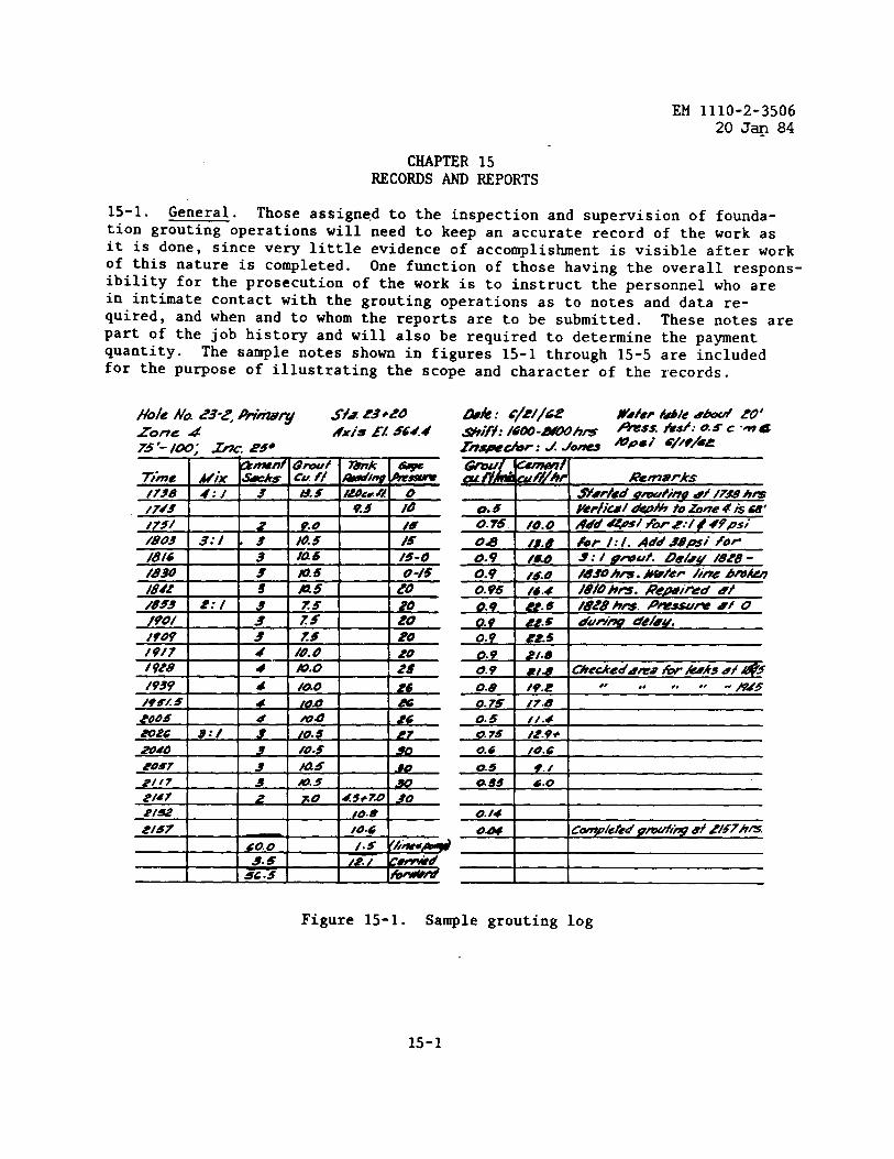
EM 1110-2-350620 J* 84
CHAPTER 15RECORDS AND REPORTS
15-1. General. Those assigned to the inspection and supervision of founda-tion grouting operations will need to keep an accurate record of the work asit is done, since very little evidence of accomplishment is visible after workof this nature is completed. One function of those having the overall respons-ibility for the prosecution of the work is to instruct the personnel who arein intimate contact with the grouting operations as to notes and data re-quired, and when and to whom the reports are to be submitted. These notes arepart of the job history and will also be required to determine the paymentquantity. The sample notes shown in figures 15-1 through 15-5 are includedfor the purpose of illustrating the scope and character of the records.
,-.Z-
/749 I I I I ..- , .-,*z/ . I A.
2/= 1 1 I I /0.8 I2/57 /0.6
-
O.a Iq.z *8 ,, ., ,. “ Hd5
0.75 /7.8
0.5 //.4a 7s /2.9+
0.6 /0.6
a5 r./ass 6.0
I I
Figure 15-1. Sample grouting log
15-1

EM 1110-2-3506
20 Jan 84
I I I I IZONE: z
HOLE N : 75 Cf ASS: Ptimry STAGF. I
QE V.Oi COLLdR: Sbo EllEv,Rock: 549STAGE i LEV. TdP: Sd/ iBOT: 15/5
I I I I II 1
TIME ELEV. ~ ORI UI MANIFESTATIONS
Z:mm 531 SmoobOpefotiIs . .
,“ mf-- 1 I 1 , ,.tky I
#:58 I 5/s 160’ I J* tO f~hI I I
Figure 15-2. Sample notes for noncoring drilling
15-2
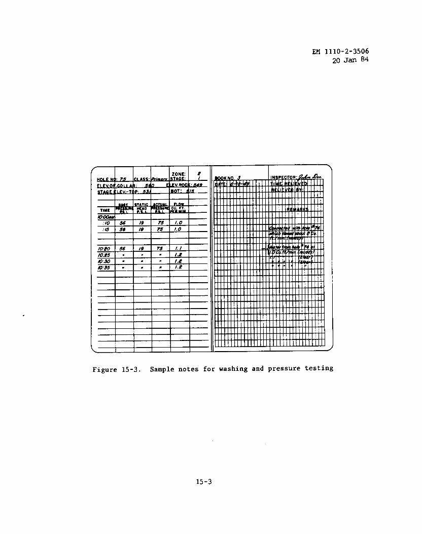
EM 1110-2-3506
20 Jan 84
I i I I 1
I 1 I 1I
z/O:E5 I - I m I . 1/91
=ml.l. l. I /..e 1
I 1 1 1 I
o S6i/9175] f./ 11 1 , . .-
.“. ”” I 1 , . .
m..?.~l.l,lm I /.2 I---- 1 I ,
, 1 1 1
Figure 15-3. Sample notes for washing and pressure testing
15-3
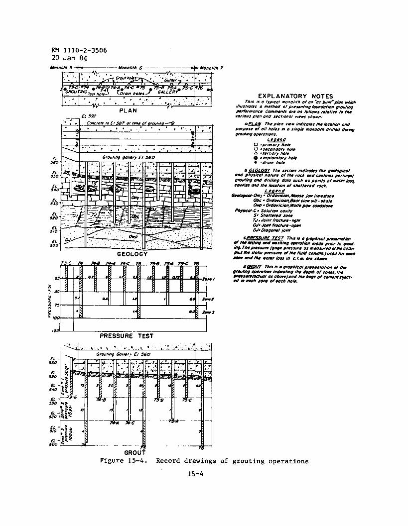
EM 1110-2-350620 Jan 84
~Oltlh5 ~— MMO~Ifh 6 --–- -—––&Monolith 7.
n 1 1 w 0
Y’”-?;,:n$h:h:y‘iz:E7P75-C“= “,, .~. “. ● .● ..,,....’ g, ..”
L“ “ “ ● ‘“’” 44A”.; “.” ● .’.”.
PLANEL 592—.
.-.
1 ‘:!
Cm?r@tOEl S87 Ottmeg rwfm. .* *”**, .“..- ~
GEOLOGY
,zs~-—~
PRESSURE TEST
.“
GROUf
EXPLANATORY NOTESrhis iso typ)colmnol,th o~on-osbudt-~mw~
dlustmks o method ofprewntmg twmdot#n gmut~
wnbrmonm. Commenk oroos bllowsmfotiuo hthovottousplonond srctmoi v)e~ shown:
a =~ Th* P~n V*W flndkotss M4 bcotim cndpurpose of o/1 holes m o smgk monoitth drilkd dumg
grouting opwot!ons.Legend
0 *pr!mo{y hokO =srcondory hokA =?Wt!ory hOk0 =explwotmy hoh● . droin hot.
b @EOLOGY The srct@ mdti~s the g~kolON ~hym”~l tloture 0/ thO rock Wld Cmtorns p,,t,mt
gmuti~ ond drillrng dofo such os points of wotff ~s~
cov~d & the focottin of shottered roch.
Figure 15-4. Record drawings of grouting operations
15-4

f- , ---I.-mcaw
● . .
EM 1110-2-350620 J- 84
U.k.<7
Figure 15-5. Core log sheet
15-5
EM 1110-2-350620 Jan 84
15-2. Records.
a. Figure 15-4 is presented as a suggested method of recording thegrouting accomplishments on as-built drawings. The drilling depths andthe zones are indicated in the geological section. The pressure testdata are indicated in the section designated as “Pressure Test,” and allremaining data on the grouting operations have been included in thesection marked “Grout.” Other methods allowing more detail and at a largerscale may be preferable.
b. Records and reports required for drilling and grouting are:
(1) Information for operational purpose. This constitutes factualdata on which to base decisions regarding the effectiveness of thegrouting accomplished. The information will be reviewed by designersand geologists assigned to the project in order to determine whether ornot departures should be made from the basic grouting plan.
(2) Records for payment. These data are used as a basis for de-termining the reimbursement due the contractor. The contractor willusually present a daily abstract of work accomplished indicating thelength of drilling and the number of bags of cement injected in groutingand include a list of holes for which minimum payment is expected. Theinspector’s reports will ordinarily be used as a check. The contractor,however, may not elect to keep any record of the work done, and paymentin that case will be based entirely on the inspector’s reports.
(3) Data for foundation record. These data are required for per-manent job records and for use in preparation of the “as built” drawingsand for inclusion in the final foundation report.
15-6
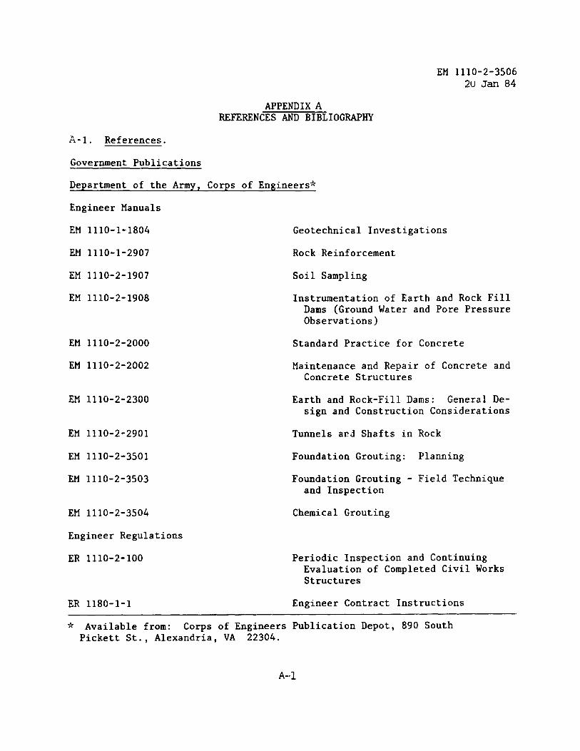
EM 1110-2-35062U Jan 84
APPENDIXAREFERENCES AND BIBLIOGRAPHY
A-1. References.
Government Publications
Department of the Army, Corps of Engineers*
Engineer Manuals
EM 1110-1-1804 Geotechnical Investigations
EM 1110-1-2907 Rock Reinforcement
EM 1110-2-1907 Soil Sampling
EM 1110-2-1908 Instrumentation of Earth and Rock FillDams (Ground Water and Pore PressureObservations)
EM 1110-2-2000 Standard Practice for Concrete
EM 1110-2-2002 Maintenance and Repair of Concrete andConcrete Structures
EM 1110-2-2300 Earth and Rock-Fill Dams: General De-sign and Construction Considerations
EM 1110-2-2901 Tunnels ax?dShafts in Rock
EM 1110-2-3501 Foundation Grouting: Planning
EM 1110-2-3503 Foundation Grouting - Field Techniqueand Inspection
EM 1110-2-3504 Chemical Grouting
Engineer Regulations
ER 1110-2-100 Periodic Inspection and ContinuingEvaluation of Completed Civil WorksStructures
ER 1180-1-1 Engineer Contract Instructions
* Available from: Corps of Engineers Publication Depot, 890 SouthPickett St., Alexandria, VA 22304.
A-1
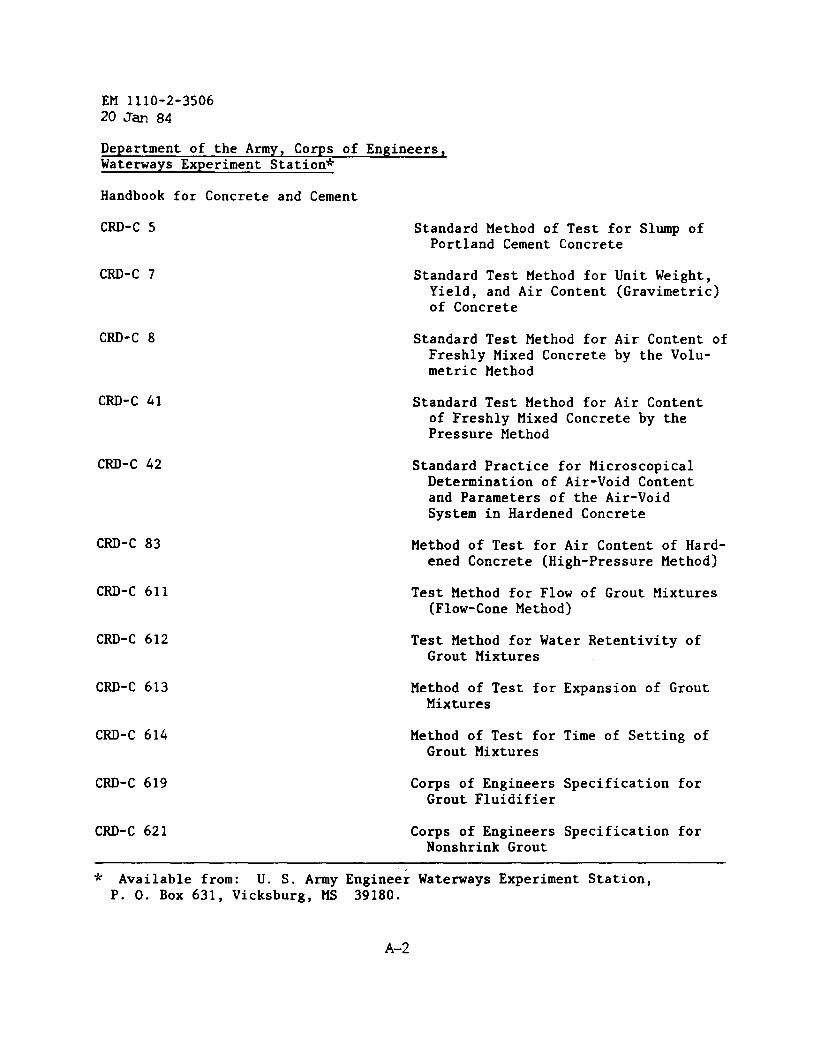
EM 1110-2-350620 Jan 84
Department of the Army, Corps of Engineers,Waterways Experiment Station*
Handbook for Concrete and Cement
CRD-C 5
CRD-C 7
CRD-C 8
CRD-C 41
CRD-C 42
CRD-C 83
CRD-C 611
CRD-C 612
CRD-C 613
CRD-C 614
CRD-C 619
CRD-C 621
Standard Method of Test for Slump ofPortland Cement Concrete
Standard Test Method for Unit Weight,Yield, and Air Content (Gravimetric)of Concrete
Standard Test Method for Air Content ofFreshly Mixed Concrete by the Volu-metric Method
Standard Test Method for Air Contentof Freshly Mixed Concrete by thePressure Method
Standard Practice for MicroscopicalDetermination of Air-Void Contentand Parameters of the Air-VoidSystem in Hardened Concrete
Method of Test for Air Content of Hard-ened Concrete (High-PressureMethod)
Test Method for Flow of Grout Mixtures(Flow-Cone Method)
Test Method for Water Retentivity ofGrout Mixtures
Method of Test forMixtures
Method of Test forGrout Mixtures
Corps of EngineersGrout Fluidifier
Corps of EngineersNonshrink Grout
Expansion of Grout
Time of Setting of
Specification for
Specification for
* Available from: U. S. Army Engineer Waterways Experiment Station,P. O. Box 631, Vicksburg, MS 39180.
A-2
EM 1110-2-350620 Jan 84
Miscellaneous PaperC-78-19
Miscellaneous Paper ,SL-79-23
Technical MemorandumNo. 6-380
_-Tech’i~~l ‘We~~No. 6-419, Reports 1through 5
Grouting of Scoured Foundation, OldRiver Low Sill Structure, Louisiana
Grouting Instrumentation, Old RiverLow Sill Control Structure
Investigation of Suitability of PrepaktConcrete for Mass and ReinforcedConcrete Structures
Tests of Sanded Grouts
Report 1 Influence of Chemicals andMineral Fines on Pumpability
Report 2 Influence of Sand Grading andAddition of Mineral Fines onPumpability
Report 3 Influence of Grading andSpecific Gravity of ManufacturedSal~dson Pumpability
Report 4 Influence of ManufacturedSands and Admixtures on Pumpability,and Evaluation of a Concrete Mixer
Report 5 Effects of Fly Ash in GroutingCoarse Sands and Fine Gravels
Maintenance and Repair Practices,Facilities Engineers
Technical ReportC-78-4, Report 1
Translation No. 65-4
. A-2.” Bibliography.
Aastrup, A. and S. Sallstrum,Non-Resistant Rock,” 7thport 69 (1961).
Maintenance and Preservation of ConcreteStructures, an Annotated Bibliography
Use of Resins for Repairing GroutingCracks and Waterproofing the Face ofa Dam
.-.
“Bergeforsen - A Swedish Power Plant Built onCongress on Large Dams, Rome, Question 25, Re-
. .
A-3
EM 1110-2-350620 Jan 84
Acker, R. C. and J. C. Jones, “Foundation and Abutment Treatment for RockfillDams,” Journal, Soil Mechanics and Foundation Division, ASCE, Vol 98,No. SM 10, Paper 9309, pp 995-1015, Ott (1972).
American Society of Civil Engineers, “Purpose or Need for Grouting in theTreatment of Foundations,” Proceedings, Engineering Foundation Conference,Pacific Grove, CA (1974).
American Society of Civil Engineers, “Grouting in Geotechnical Engineering,”Proceedings (1982).
American Society for Testing and Materials, Philadelphia, PA, Standard TestMethod for Restrained Expansion of Skrinkage Compensating Concrete, Desig-nation: C-878-78 (1978).
Bussey, W. H., “Control of Seepage Through Foundation and Abutments of Dams,”Foundation Evaluation and Treatment, Casagrande Geotechnique, Vol 11,No. 3, 1961, pp 161-182 (1961).
Cabanius, C. and R.(1958).
Cambefort, H., “TheGeol., Vol 10,
Margre, “The Serre-Poncon Dam,” Travaux, Paris, p. 43
Principle and Applications of Grouting,” Q. J1. Engrg.pp 57-95 (1977).
Clough, G. W., Development of Design Procedures for Stabilized Soil SupportSystems, U. S. Department of Commerce, PB 272 771.
Department of the Army, Corps of Engineers, Geophysical Exploration,EM 1110-1-1802.
Gelhart, High Earthfill Dam Foundation, Grouting Design and ConstructionProcedures, ASCE Natl. Mtg., Res Eng., New Orleans, LA, (1969).
Hernton, J. and T. Lenahan, Grouting in Soils, Vols 1 and 2, Federal HighwayAdministration, PB 259 043 and PB 259 044.
Jaworski, G. W., J. M. Duncan, and H. B. Seed, An Experimental Study of Hydrau-lic Fracturing, Report No. UCB/GT/79-02, University of California,Berkeley, CA, Ott (1949).
Jevdjevic, V. M., and B. M. Rajcevic, “Some Special Features of Designs andConstructions for Earth Dams and Rockfill Dams in Yugoslavia,” Journilz4th Congress on Large Dams, New Delhi, India, Vol 1, p. 153 (1951).
Karol, R. H., P.E., Soils and Soils Engineering, Prentice-Hall, Inc.
A-4
EM 1110-2-350620 Jan 84
Neff, T. L., J. W. Sager, and J. B. Griffiths, “Consolidation Grouting at anExisting Navigation Lock,” Grouting Geotechnical Engineering, ASCE (1982).,
Sherard, J. L., et al., Earth and Rockfill Dams, John Wiley & Sons, Inc.,New York (1963).
Sinclair, B., Estimation of Grout Absorption in Fractured Rock Foundations,Published on demand by Univ. Microfilms, Intl., Ann Arbor, Michigan, andLondon, England (1972).
Soil Mechanics Lecture Series: Design and Construction of Earth Structures(sponsored by Soil Mechanics and Foundation Division, Illinois Section,ASCE and Civ Eng Dept, Illinois Inst. of Tech., Chicago, IL, pp 93-115.
Tallard, G. R. and C. Caron, Chemical Grouts for Soils, Vols 1 and 2, FederalHighway Administration, Reports FHWA-RD-77-50 and FHWA-RD-7751, June(1977).
Thompson, T. F., “Foundation Treatment for Earth Dam,” Proceedings, ASCE (1954).
Underwood, L. B., “Engineering Classificationof Shale,” ASCE paper (1967).
U. S. Army Engineer Waterways Experiment Station, CE, Bibliography on Grouting,Miscellaneous Paper C-78-8, June (1978).
. Zeigler, T. W., Determination of Rock Mass Permeability, U. S. Army EngineerWaterways Experiment Station, Technical Report S-76-2.
A-5
.
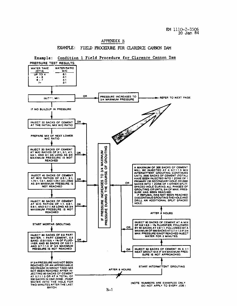
EM lll&2-350620 Jan 84
Example: Condition 1 Field Procedure for Clarence Cannon DamPRESSURE TEST RESULTS
E--T
tlNiT’”l. Ml? PRESSURE INCREASES TO
314MAXIMUM PRESSURE I REFER TO NEXT PAGE
IIF NO BUILDUP IN PRESSURE
1
PREPARE MIXOF NEXT LOWERW/C RATIO
4
INJECT 40SACKS OF CEMENT
k
AT W/C RATIOS OF 2.5:1, 2:1, OR1.75:1,1.5:1,AND 1.2S1ASLONGAS3/4MAXlMUM PRESSURE IS
NOT REACHED
+
INJECT 60 SACKS OF CEMENTAT WIC RATIOS OF 1:1, 0.9:1, OR0.8:1,AND0.7:1 AsLoNGAs3/4MAXIMUM PRESSURE IS NOT
REACHED
ISTART MORTAR GROUTING
,INJECT 30 SACKS OF0.9 PARTWATER, 1 PART CEMENT, 0.5SAND. [0.91:0.5) +l%OFFLUIO- &IFIER AND BOSACKS OF O.E1:lAND 0.7:1:1.5 IF 3/4 MAXIMUMPRESSURE IS NOT REACHED
I
t
OR
L
AMAXIMUMOF 300SACKS OF CEMENTWILL BE INJECTED AT A 0.7:1:1.5 MIXINTERMITTENT GROUTING CONTINUESUNTIL-SACKS OFCEMENT (TOTAL)HAVEBEENINJECTED INTOIZONEOF 1PRIMARYOR SECONDARY HOLEOR2GI0SACKS INTO I ZONE OF I OTHER SPLIT-SPACED HOLE DURING ALL PHASESOFGROUTINGORUNTIL W40FMAX.PRES-SURE HAS BEEN REACHEO.
IFREFUSALHAS NOTBEEN REACHEDDISCONTINUEGROUTING THEHOLEANDDRILL AN ADDITIONAL SPLIT SPACEDHOLE.
E
fAFTER 8HOURS
-i
INJECTSOSACKS OFCEMENTAT AMIXOF 0.9:1:0.5+ 1% FLUIDIFIER, FOLLOWED
OR BY 50 SACKS AT 0.61:1, FOLLOWED BY AMAXIMUMOF 500SACKSAT 0.7:1:1.5IF3/4MAX.PRESSUREISNOTREACHED INJECT
WATER FOR 2 MINUTES.
~
INJECT SOSACKS OF CEMENT IN A 1:1NEAT GROUT MIX IF 3/4 MAXIMUMPRES-
IF 3/4 PRESSURE HAS NOT BEENREACHEO OR AN APPRECIABLEDECREASE INGROUT TAKE HAS
::~~f:~~~::~:MJfi ~300SACKS IN ONE ZONE - PUMP
tSTART INTERMITTENT GROUTING
AFTER E HOURS I
WATER INTO THE HOLE FORTWO MINUTES AFTER THE LAST
BATCH
(NOTE: NUMBERS ARE EXAMPLES ONLYDO NOT APPLY TO EVERY JOB.)
B-1
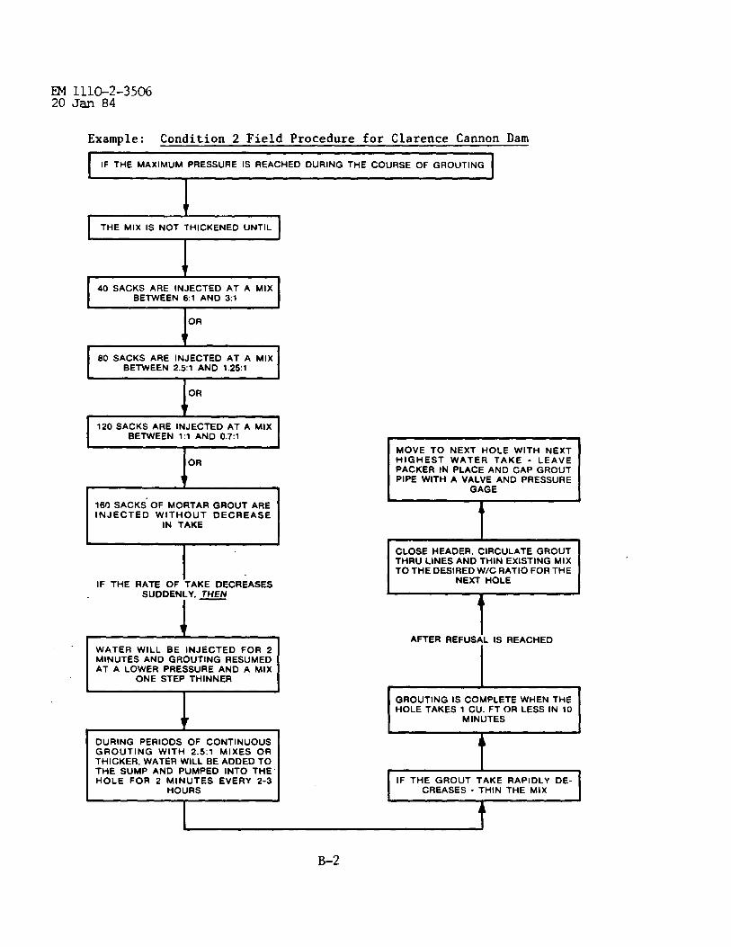
Example: Condition 2 Field Procedure for Clarence Cannon Dam
IIF THE MAXIMUM PRESSURE IS REACHED DURING THE COURSE OF GROUTING I
It
I THE MIX IS NOT THICKENED UNTILI
It
40 SACKS ARE INJECTED AT A MIXBETWEEN 61 AND 3:1
OR
1‘
80 SACKS ARE INJECTED AT A MIXBETWEEN 2.5:1 AND 1.25:1
I 120 SACKS ARE INJECTED ATA MIXBETWEEN 1:1 AND 0.7:1
IIOR
It
1
I160 SACKS’OF MORTAR GROUT AREINJECTED WITHOUT DECREASE
IN TAKEI
IF THE RATE OF-TAKE DECREASESSUDDENLY, THEN
l–
t
DURING PERIODS OF CONTINUOUSGROUTING WITH 2.5:1 MIXES ORTHICKER,WATER WILL BEADDED TOTHE SUMP AND PUMPED INTO THEHOLE FOR 2 MINUTES EVERY 2-3
HOURS
I
MOVE TO NEXT HOLE WITH NEXTHIGHEST WATER TAKE - LEAVEPACKER IN PLACE AND CAP GROUTPIPE WITH A VALVE AND PRESSURE
GAGE
r“THRU LINES ANO THIN EXISTING MIXTO THE DESIRED WIC RATlO FOR THE
1AFTER REFUSAL IS REACHED
II
GROUTING IS COMPLETE WHEN THEHOLE TAKES 1 CU. FT OR LESS IN 10
MINUTES I
I IF THE GROUT TAKE RAPIDLY DE-CREASES - THIN THE MIX I
1
B-2
EM 1110-2-350620 Jan 84
Example: Condition 3 Field Procedure for Clarence Cannon Dam
Once the rate of grout take has begun to steadily decrease, the mixtureshall not be thickened further.
If there is a rapid decrease in the rate of grout take, the mixtureshould be thinned.
B-3
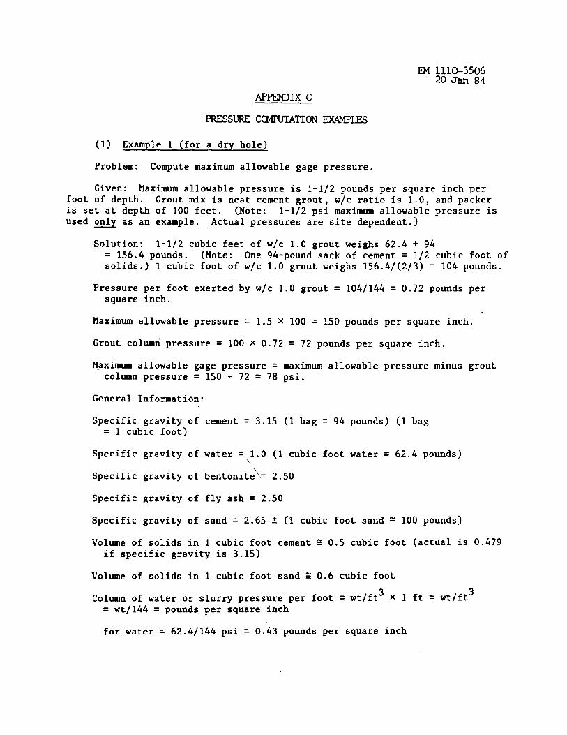
APPENDIX C.—
PRESSURE CmATION
(1) Example 1 (for a dry hole)
Problem: Compute maximum allowable gage pressure.
Given: Maximum allowable pressure is 1-1/2 pounds per square inch perfoot of depth. Grout mix is neat cement grout , w/c ratio is 1.0, and packeris set at depth of 100 feet. (Note: 1-1/2 psi maximum allowable pressure isused only as an example. Actual pressures a;e site dependent.) -
Solution: 1-1/2 cubic feet of w/c 1.0 grout weighs 62.4 + 94= 156.4 pounds. (Note: One 94-pound sack of cement = 1/2 cubic foot ofsolids.) 1 cubic foot of w/c 1.0 grout weighs 156.4/(2/3) = 104 pounds.
Pressure per foot exerted by w/c 1.0 grout = 104/144 = 0.72 pounds persquare inch.
Maximum allowable pressure = 1.S X 100 = 150 pounds per square inch.
Grout colti pressure = 100 X 0.72 = 72 pounds per square inch.
H.aximum allowable gage pressure = maximum allowable pressure minus groutcolumn pressure = 150 - 72 = 78 psi.
General Information:
Specific gravity of= 1 cubic foot)
Specific gravity of
Specific gravity of
Specific gravity of
Specific gravity of
Volume of solids inif specific gravity is 3.15)
cement = 3.15 (1 bag= 94 pounds) (1 bag
water = 1.0 (1 cubic foot water = 62.4 pounds)‘\
bentonit>’= 2.50
fly ash = 2.50
sand = 2.65 t (’1cubic foot sand = 100 pounds)
1 cubic foot cement ~ 0.5 cubic foot (actual is 0.479
Volume of solids in 1 cubic foot sand S 0.6 cubic foot
Column of water or slurry pressure per foot = wt/ft3 Xlft= wt/ ft3= wt/144 = pounds per square inch
for water = 62.4/144 psi = 0.43 pounds per square inch

m 111s2-350620 Jan 84
for 1:1 grout (above water table) = (62.4 + 94)/(1.5 x 144)= 0.724 pounds per square inch
for 1:1 grout (submerged) = (62.4 + 94)/(1.5 x 144) - (62.4/144)= 0.294 pounds per square inch
c-2
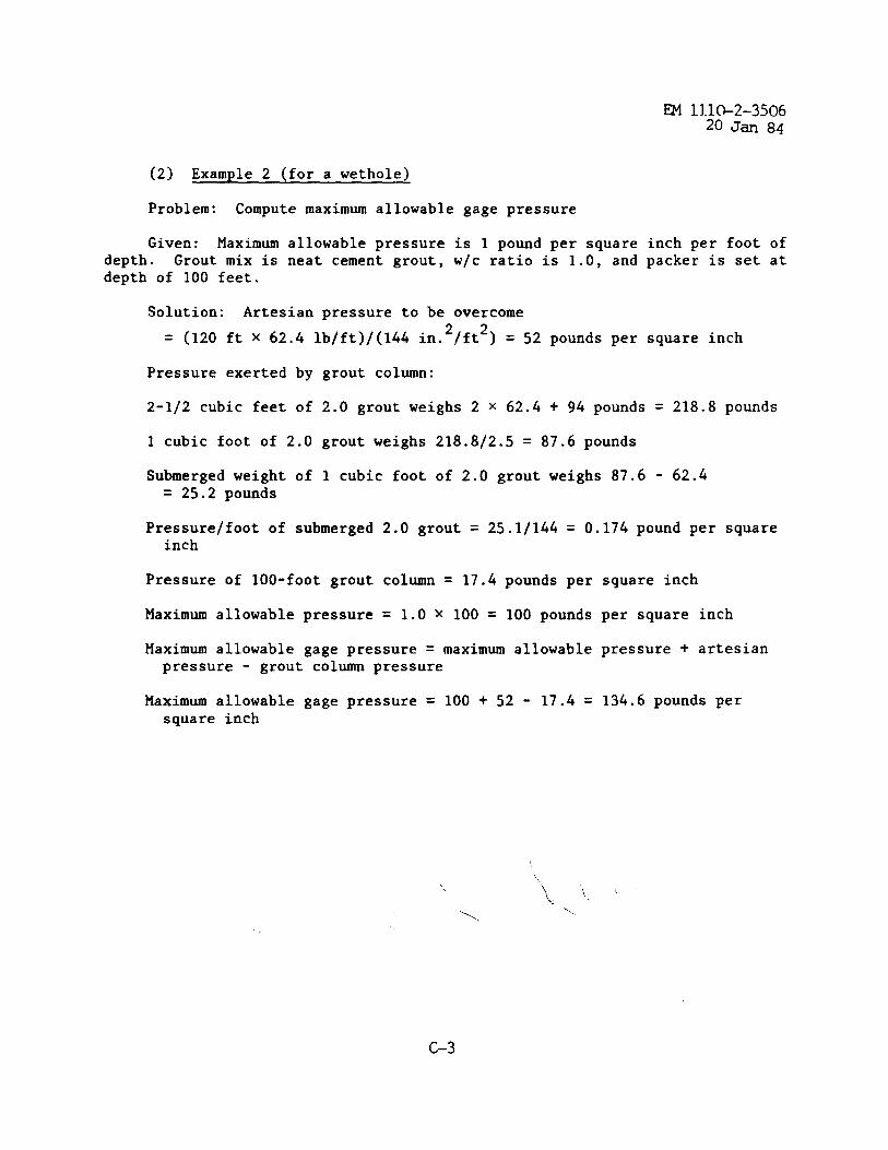
~ 11.l&2-350620 J- 84
(2) Example 2 (for a wethole)
Problem: Compute maximum allowable gage pressure
Given: Maximum allowable pressure is 1 pound per square inch per foot ofdepth. Grout mix is neat cement grout, w/c ratio is 1.0, and packer is set atdepth of 100 feet.
Solution: Artesian pressure to be overcome
= (120 ft x 62.4 lb/ft)/(144 in.2/ft2) = 52 pounds per square inch
Pressure exerted by grout column:
2-1/2 cubic feet of 2.0 grout weighs 2 x 62.4 + 94 pounds = 218.8 pounds
1 cubic foot of 2.0 grout weighs 218.8/2.5 = 87.6 pounds
Submerged weight of 1 cubic foot of 2.0 grout weighs 87.6 - 62.4= 25.2 pounds
Pressure/foot of submerged 2.0 grout = 25.1/144 = 0.174 pound per squareinch
Pressure of 100-foot grout column = 17.4 pounds per
Maximum allowable pressure = 1.0 x 100 = 100 pounds
Maximum allowable gage pressure = maximum allowablepressure - grout column pressure
Maximum allowable gage pressure = 100 + 52 - 17.4 =square inch
square inch
per square inch
pressure + artesian
134.6 pounds per
\/
‘/.‘..
c-3
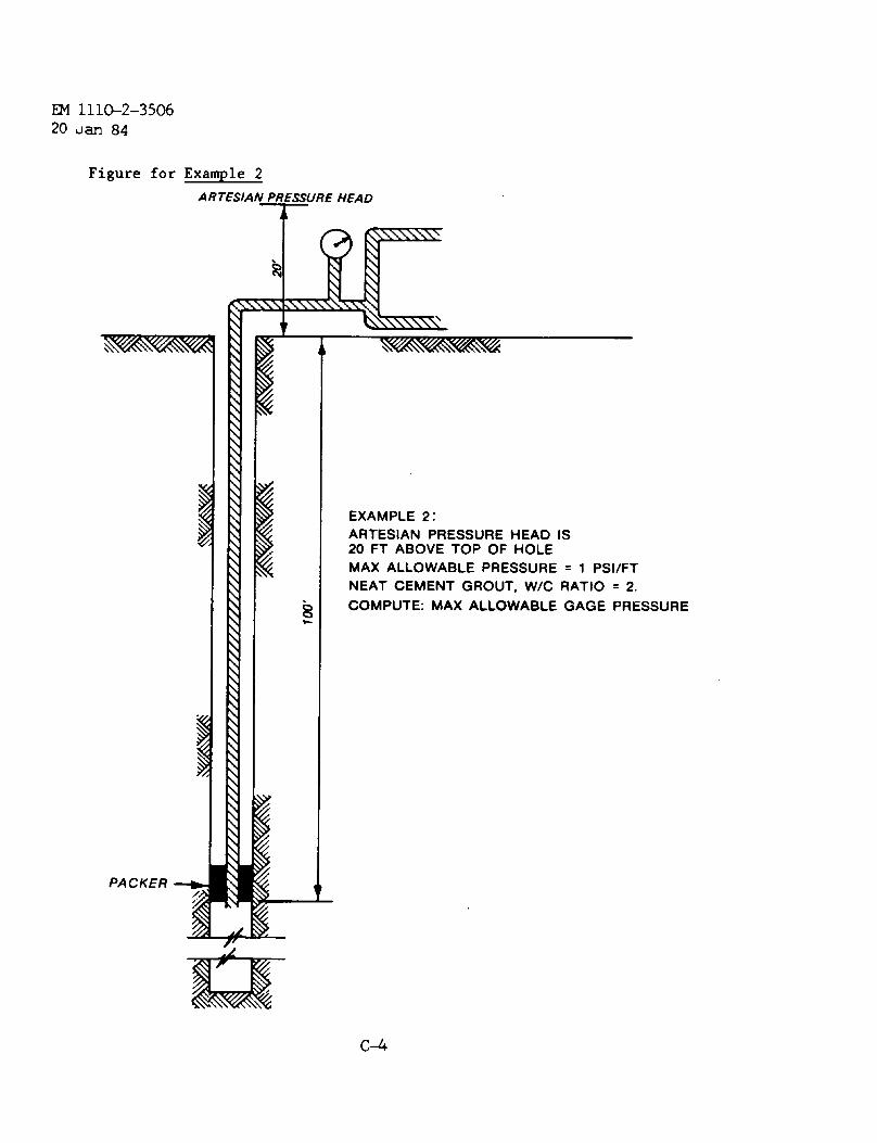
m 1110-2-350620 uan 84
Figure for Example 2
ARTESIAN PR-ESSURE HEAD
4
PACKER +
EXAMPLE 2:ARTESIAN PRESSURE HEAD IS20 FT ABOVE TOP OF HOLEMAX ALLOWABLE PRESSURE = 1 PS1/FTNEAT CEMENT GROUT, W/C RATIO = 2.
COMPUTE: MAX ALLOWABLE GAGE PRESSURE
c-4
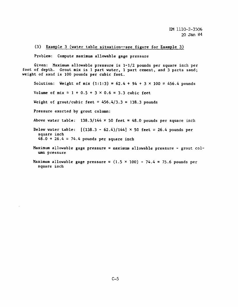
EM 1110-2-350620 Jan 84
(3) Example 3 (water table situation--see figure for Example 3)
Problem: Compute maximum allowable gage pressure
Given: Maximum allowable pressure is 1-1/2 pounds per square inch perfoot of depth. Grout mix is 1 part water, 1 part cement, and 3 parts sand;weight of sand is 100 pounds per cubic foot.
Solution: Weight of mix (1:1:3) = 62.4+ 94 + 3 x 100 = 456.4 pounds
Volume of mix = 1 + ().5+ 3 X 0.6 = 3.3 cubic feet
Weight of grout/cubic feet = 456.4/3.3 = 138.3 pounds
Pressure exerted by grout column:
Above water table: 138.3/144 x 50 feet = 48.0 pounds per square inch
Below water table: [(138.3 - 62.4)/144] x 50 feet = 26.4 pounds persquare inch48.0 + 26.4 = 74.4 pounds per square inch
Maximum allowable gage pressure = maximum allowable pressure - grout col-umn pressure
Maximum allowable gage pressure = (1.5 x 100) - 74.4 = 75.6 pounds persquare inch
c-5
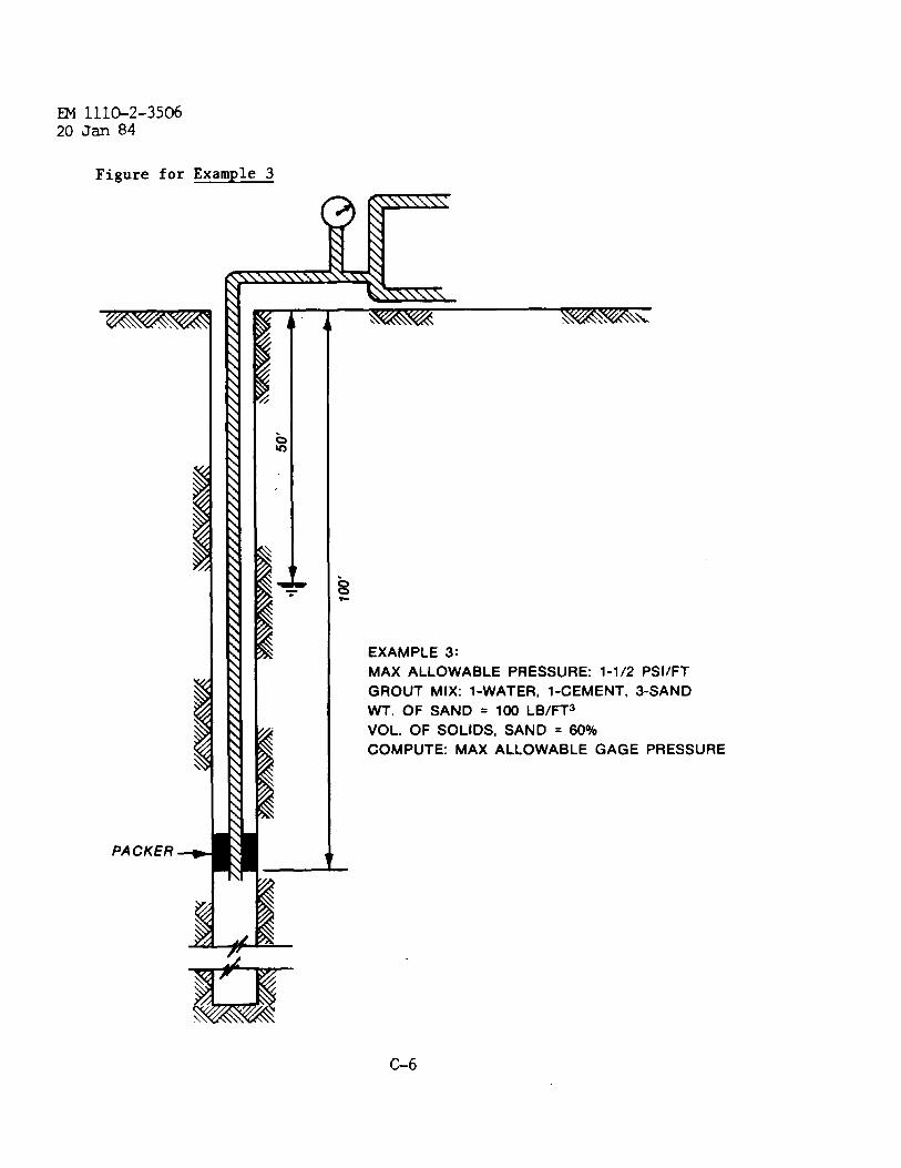
m 111G2-350620 Jan 84
Figure for Example 3
~
PACKER -
EXAMPLE 3:
MAX ALLOWABLE PRESSURE: 1-1/2 PS1/FT
GROUT MIX: l-WATER, l-CEMENT, 3-SAND
WT. OF SAND = 100 LB/FT3
VOL. OF SOLIDS, SAND = 60%
COMPUTE: MAX ALLOWABLE GAGE PRESSURE
C-6
~ llL&2-350620 Jan 84
(4) Example 4.
Rock is thinly bedded limestone with numerous bedding plane joints andshale partings.
Unit weight of rock yrock = 162 pounds per cubic foot
(~) What is recommended maximum grouting pressure?
Solution: 162/144 = 1.125 pounds per square inch per foot of depth
(Q) If water table is at 50 feet and the packer is set at 50 feet, whatis recommended gage pressure range?
Anticipated grout mix is cement grout , and water cement ratios may varyfrom 6.0 to 1.0.
Solution: For 1.0 grout, gage pressure = 1.125 - (62.4 + 94)/(1.5 x 144)= 0.4 pound per square inch per foot
For 6.0 grout, gage pressure = 1.125 - (6 x 62.4 + 94)/(6.5 x 144)= 0.5 pound per square inch per foot
At 50-foot depth, the range would be from 0.4 x 50 to 0.5 x 50, or 20 to25 pounds per square inch
C-7
EM 1110-2-3506
20 Jan 84
APPENDIX DPHYSICAL CHARACTERISTICS OF SANDED GROUTS
The physical data noted in Tables D-1 through D-4 and Figures D-1 and D-2covering the investigation of sanded grout mixtures are provided from WES Tech-nical Memorandum 6-419 to show the sand-carrying capacity of various pumpablemixtures as well as to furnish information regarding setting times andstrength development with age for such mixtures. The addition to these mix-tures of such additives as retarders, accelerators, water reducers, expansiveagents, and air-entraining agents will modify the fluid properties as well asthe hardened physical properties to meet various project requirements for newconstruction, remedial work, and grouting associated with research and de-velopment experiments.
D-1
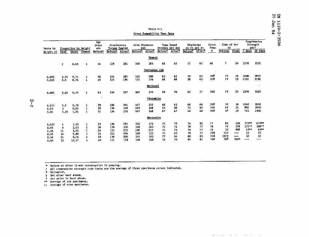
Table o-1
Grout Pumpability Test 13ata
u
Age C0mvre88ivem
St;ength zpait
-=
Griut Consistency Line PressureParts by
Pump Speed Discharge Grout Time of SetProportion by Weight mln Torque Degree psi Strokes per min Cu ft per hr Temp hr
Weip,ht of Sand Water Cement Before* Before* After* Before* After* Before* After* Before* After* F Initial Final.— .— —— —— —— —— —— —
Cement
183 65
Intrusion Aid
200 63170 68
Hethocel
170 69
niatcaite
152 68168 65148 67
Bentonite
172 71163 71215 71155 71163 77140 74
168
141155
65 57 63
6363
57
666569
821777778381
66
70*70*
70+
70*70+70*
77787270+70+70*
?
7s75
75
3s4535
8S7s35
7251225
713*
24
2423
23
182119
221271891
..-
1570 35352
2.252.5
2.25
2.533.25
‘46
11142432
0.65
0.710.74
0,72
0.790.951.01
1.352.033.555.889.76
12.17
1 26
30: 29
1 43
129
134133
130
130136134
136136133141138131
181
182194
5958
1400 28101130 2190
0.0050.020
0.002
0.0150.030.06
0.0250.050.100.200.300.40
62 1270 2625257 165 70
636067
667168
1240 2650860 18407.45 1900
1
11
292931
164148176
191210212204206178
147153147
152148
375** 670**175t+ 308tt
43** 634*
15 2510 10
-— ---
232624242940
707175636470
747879798884
190
140145140 500$
● Before or after 15-min interruption in pumping.t All compressive strennth CU~ tests are the average Of three specimns unless indicated.f Estimata.$ Set after ho(tr shown.I Set prior to hour shown.
** Average of six specimens.ft Average of nine specimens.
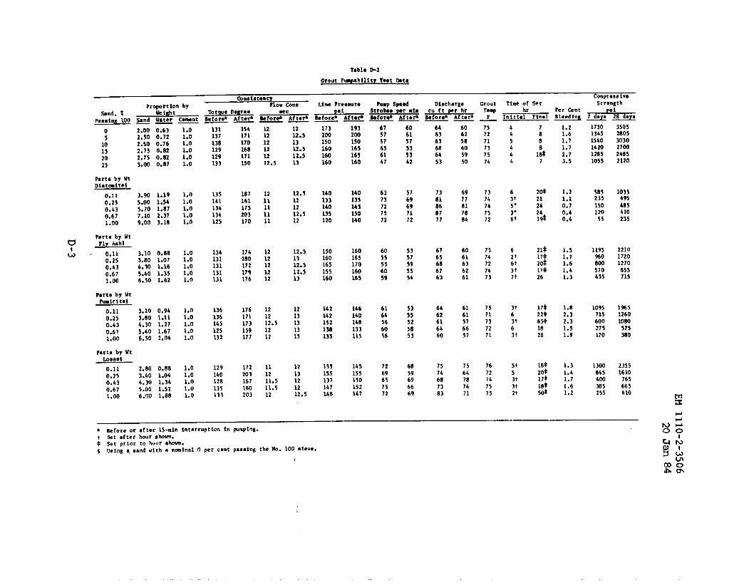
Tablo D-2
c90918tencvPropo rt ion by
Compress iveFlow mne Line Pres8ure Pump speed Discharge Grout Time of Set
%nd, Z w i8bt TOraue Degree ●ec Itmi StrohoStrength
mr ●in Cu ft wr h? Teq hr Per &ntPasa ing 100 Sand Ifarer @merit 8ef ore* Af te+
fls i8efore* Aftefl 8efore* Aftefl Sefore* Afte@ &fore* Afrer* F—— —— —— — —— — Initial Fi”sl Bleed- A M
o 2.00 0.63
5 2.50 0.7210 2.50 0.7615 2.75 0.S220 2.73 0.s225 3.00 0.s7
Parts by Wtoiat0aite5
0.11 3.90 1,19
0.25 5.00 1.540.’43 5.70 1.870.67 7.10 2.371.00 9.00 3.18
Parts by Wtu Fly kh!
& .“ 0.11 3.10 0.s80.25 3.80 1.070.43 4.3o 1.160.67 5.40 1.351.00 6.50 1.62
Parts by Wtruicitef
0.11 3.10 0.940.25 3.80 1.110.43 4.30 L.270.67 5.40 1.671.00 6.50 2.04
Parta by WtLQeess
0.11 2.80 0.88
0.25 3.40 1.040.43 4.30 1.34
0.67 5.00 1.521.00 6.00 1.88
1.01.01.01.01.01.0
1.01.01.01.01.0
1.01.01.01.01.0
1.01.01.01.01.0
1.01.01.01.01.0
131137138129129133
135141134134125
134131131131131
136136145125132
129140128135133
154171170168171230
187161175203170
17418017217$176
176171173159177
172203167180203
121212121212.5
1211
:;11
1212121212
121212.51212
111211.511.512
1212.51312.512.513
12.5121212.512
12.51312.512.513
1213131313
1213121212.5
173200150160160160
140133140135120
150160165155160
142142152138135
135155137147I&s
193200150165165160
140135145150140
160165170160165
14614014s133115
145155150152lb7
675757656147
6373727572
6055556059
6164566056
7269657572
606157535342
5769697172
5357595554
5355525853
6859696669
6463636S6453
7381868777
67656S6763
6462616460
75746873S3
606258605950
6977S17884
6061636261
6161576657
75647s7471
757271737574
7374747572
7374727473
7571737271
7672741575
44546h
6‘jtSt3?6t
6Zt6tjt7t
3t63t6It
5+53t3t2t
788
127
Z@21242414
21*17$2d17$26
17*22+6H1826
18+20$
17*18*
5&
1.21.61.71.72.73.5
1.21.10.70.40.4
1.51.71.61.41.3
1.82.32.31.51.9
1.31.41.71.61.2
173013451540142012851055
585235
150120
55
1195%0800570435
1095715600275170
1300845400385255
350528053030270024852120
1035495
485410235
221017201270
855715
1%512601080
575380
23551610
765665h 10
~fore or after 15-min interruption in pumptns. m-
Set after hour shown. 00
set prior to l~~ur shwn.
Using q sand with a nminnl O per cent paaaing the No. 100 sieve.
i!I
a)~Am
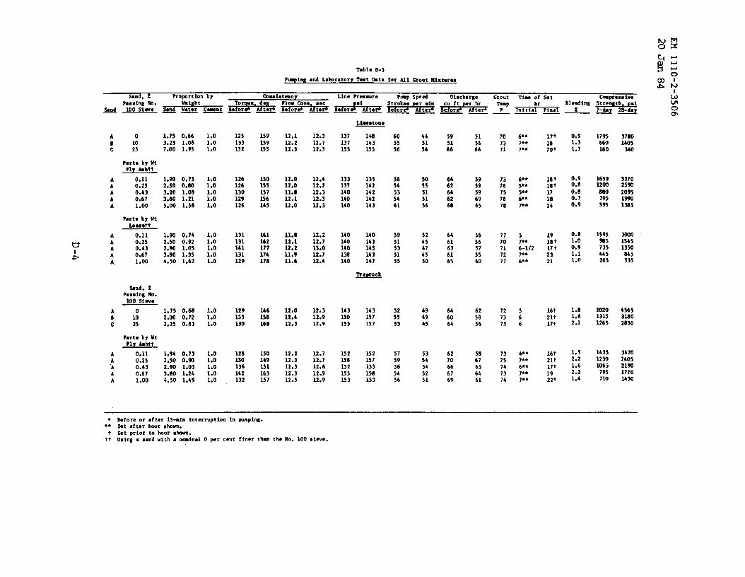
A o 1.7s 0.6610 3.25 1.0S
: 25 7.00 1.95
Parts by 4ftPly hhtt
A 0.11 1.90 0.73A 0.25 2.50 0.S0A 0.43 3.20 1.08A 0.67 3.80 1.21A 1.00 5.oO 1.58
Parts by WtLO*sstt
A 0.11 1.90 0.74A 0.25 2.50 0.92A 0.43 2.90 1.05A 0.67 3.80 1.35A, 1.00 4.5o 1.62
%nd, XPassing M.
100 S1W8
A 1.75 0.60B 1: 2.00 0.72c 25 2.25 0.83
Parta by 14tPly A6htt
A 0.11 1.94 0.73A 0.2s 2.50 0.90“A 0.43 2.90 1.03A 0.67 3.tfO 1.24A 1.00 4.50 1.49
1.01.01.0
1.01.01.01.01.0
1.01.01.01.01.0
1.01.01.0
1.01.01.01.01.0
125133232
126126130129126
131131141131129
129233130
128130136142132
1s9239355
150335257256145
161162177174178
146Ha168
150149251163157
12.112.212.3
12.012.011.812.112.0
11.812.112.211.911.6
12.0IZ.412.3
12.212.312.312.312.5
12.312.712.3
12.412.212.312.322.3
12.212.713.012.712.4
12.312.912.9
12.712.712.612.912.9
Lkatona
137 148237 143353 155
133 135137 142140 142140 142140 143
140 140140 143140 14513s 143140 147
143 143330 157235 157
232 1522.58 157232 153U5 158253 153
605556
5654535461
5951535155
525s53
5759565456
445154
so55515156
5245474550
494945
5354545251
59
;;
6462646268
6461636165
646064
6270666769
515666
5959596965
5656575560
625856
5867656461
707371
;:757878
7770717277
727375
7375747374
17t
1870+
18 t
18t171s24
1918 t17 t2321
16t21t17t
16t21*17t1922t
0.91.31.7
0.90.8
0.80.70.9
0.111.00.91.11.0
1.81.62.1
1.52.21.62.21.4
1795660160
16501200
Wo795595
1595%5735445265
202013231265
14352230106J
795710
37801405
340
337025W
209519m1325
300023451350
245535
456532s0283o
34202405219017701430
● Sefore or ●fter 23-in interruption in pumping.●* *t after hour ahOvn.
t Set prior to haur chaun.t+ using a sand with ● nminal O per cent finer tlun the P?o. 100 sieve.
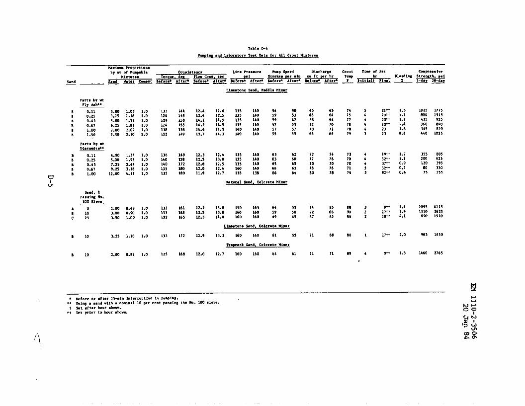
Table *4
P~ilts Snd Mborato?y Teat hta for A31 Grout Mixtures
Mxima ROOOrtiOnO
Sand—
Part# by utFly hw*
B 0.11B 0.25B 0.43B 0.67B 1.00B 1.50
Parts by -Diatait#*
B 0.11B 0.25B 0.43B 0.67
uB 1.00
&
tind; XPSSSIWb.
100 sieve
A oB 10c 25
B 10
B 10
b~ ut of P&pableHixturea
Sand water -men:.— —
3.00 1.03 1.03.75 1.1s 1.05.00 1.51 1.06.25 1.83 1.07.00 2.02 1.07.50 2.10 1.0
4.50 1.54 1.05.00 1.93 1.07.25 2.44 1.09.25 3.18 1.0
12.00 4.17 1.0
2.00 0.6B 1.03.00 0.9Q 1.03.50 1.00 1.0
3.25 1.10 1.0
2.00 0.82 1.0
Coon ictency Line Pre*mur*Torque. deu
Wp speed oi~charse Crout Ti-t of Set C.mpreaa ive. . . .
Before* Af te+——
133124129124138132
136140140135135
132133132
133
125
144149158255156149
149238172260180
16116S165
172
168
12.412.414.114.214.613.7
12.312.512.812.011.9
12.212.512.5
12.9
12.0
L&stone Snd. Pddlc Hi=?
12.6 135 140 5412.5 135 140 5914.5 135 140 5914.5 13s 140 5715.5 140 14014.3 140 140 ;;
12.4 13s 140 6313.0 135 140 6312.5 135 140 6512.4 140 140 6612.7 138 13s 66
Mtural Wnd. Cole-t* Plitir
13.0 150 163 6413.8 160 160 5914.0 160 160 69
505347555755
6260656364
555045
Lfnstone Mnd, tileratt Mixer
13.3 160 160 61 55
Trspr.aek Snd, Mleret ● Hi=r
12.7 160 160 64 61
65666B727066
72?1707s80
747267
71
71
636464707166
1476707078
656662
68
71
7475777s7879
1370707174
B89086
86
89
,
5hb443
44433
322
1
6
Zltt2fJtt20+tZlltt2323
19tt32tt37ff32++82tt
9tt17+t1s+ t
17tt
9tt
1.51.11.71.41.60.s
1.71.10.90.70.6
1.41.94.1
2.0
1.3
1025Soo435360345440
355200120
Iso75
20951310
S90
965
1460
17751515
92S84oS20
1025
B05625395330255
411526251910
1650
2765
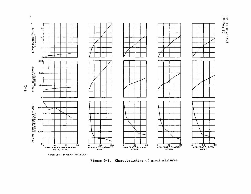
I
\
3.00
!.,,,,
2.00
.—
1.00
/ “
0
3000 -\ / \
\.
2000 -
1000
0 -0 10 20 30
SANO - PER CENT PASSINGNO. 100 SIEVE
1?
I
.
50 100:ER cENT * OIATOMITE
AODED
\
\
\
L ~
o so 100PER CENT” FLY ASH
AOOED
Figure D-1. Characteristics of
MH\\\
o so 100
PER CENT*PUMICITEA DDE O
erout mixtures
\ ,
k
\ \
o 100PER CEN’:*LOESS
ADOED
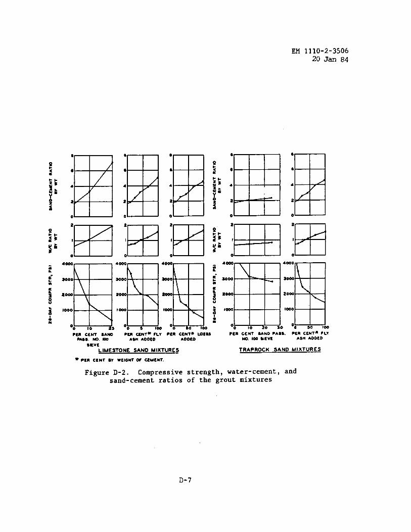
EM 1110-2-350620 Jan 84
8
9
4
2
0 @
2
I
o w
8
9
4
2
0 I
●
e
4
2
0 I
PtR CENT SAND ●cn c2NT* FLY ●Cn CENT* ~C22 Pcn CCNT 2AND ●ASS. PER C2NTn FLY
MS. No. 100 A2N ADDED AO020 w. m Sltvf ASH ADDED
SKVE
LIMESTONE SAND MIXTURES TRAPROCK SAND MIXTURES
* ●ER c~N~ By w~,c~ * ~M~Nr.
Figure D-2. Compressive strength, water-cement, andsand-cement ratios of the grout mixtures
D-7