Embed Size (px)
DESCRIPTION
Instalacion de Embrague 15.5
Citation preview
Measure Engine Flyw
heel Housing and Flywheel
Engine flywheel housing and flyw
heel must m
eet these specifications or there will be prem
ature clutch wear. Rem
ove old Pilot Bearing. All gauge contact surfaces m
ust be clean and dry. Use a dial indicator and check the following:
Measure
Clutch Adjustment and Lubricate
Flywheel Face Runout
Secure dial indicator base to flyw
heel housing face. Put gauge finger in contact w
ith flyw
heel face near the outer edge. Rotate flyw
heel one revolution. M
aximum
runout is .008" (.20 m
m).
Pilot Bearing Bore RunoutSecure dial indicator base to flyw
heel housing face. Position gauge finger so that it contacts pilot bearing bore. Rotate flyw
heel one revolution. M
aximum
runout is .005" (.13 m
m).
Flywheel Housing I.D.
RunoutSecure dial indicator base to crankshaft. Put gauge finger against flyw
heel housing pilot I.D. Rotate flyw
heel one revolution. M
aximum
runout is .008" (.20 m
m).
Flywheel Housing Face
RunoutSecure dial indicator base to flyw
heel near the outer edge. Put gauge finger in contact w
ith face of flyw
heel housing. Rotate flyw
heel one revolution. M
aximum
runout is .008" (.20 m
m).
Adjust ClutchNOTE: ServiceRanger softw
are is required to adjust the ECA clutch on an Eaton Electronic Clutch Actuator UltraShift Transmission.
Lubricate
3Double click on the transm
ission model under the
Advanced Products Functions to list the various com
mands
for the ECA.6Apply grease to the lube tube on the side of the clutch housing until grease purges from
the release bearing housing.
Connect ServiceRanger to the truck via the diagnostic port under the dashboard.
2Select the Advanced Products Functions category.
5Open the inspection cover and verify the lube tube is attached to the release bearing and the clutch housing, and is functional. After inspection is com
plete close the inspection cover to prevent contam
inants from entering the clutch
housing.
Select the Request Clutch Adjustment
comm
and to automatically initiate the
ECA to open and close the clutch five tim
es causing a clutch adjustment.
4
5
1
Measure
1Install Clutch to Flyw
heel2
Install Transmission
3Install ECA
4
Install a 15.5" Heavy-Duty ECA Clutch in 5 steps
Eaton® Fuller ® Heavy-Duty 15.5"
Adjustment-Free Clutch
1Eaton recomm
ends that the ECA Clutch use a lithium - com
plex base grease w
ith a minim
um of 325* F (163*C) operating range
meeting N.L.G.I. Grade 2 or 3 spec.
Copyright Eaton Corporation, 2010.All rights reserved.
CLMT-1400
03/11 WP
Note: Eaton requires a lube tube assembly to be
used on the Electronic Clutch Actuator Ultrashift Transm
ission System.
Note: Failed lube lines will prevent grease from
reaching the release bearing causing prem
ature clutch release bearing failure.
7Apply lube to the release yoke fingers to reduce w
ear to the pads on the release bearing housing.
8Apply grease to the cross shaft bushings through the grease zerk on the side of the clutch housing.
CAUTION: Failure to properly lubricate the bearing/bushing will result
in bearing and sleeve failures.
IMPORTANT: Do not lube the input shaft splines (never seize or grease).
Clutch Adjustment and Lubricate
5
NOTE: To remove the LCIB the transm
ission and the Electronic Clutch Actuator m
ust be removed. Refer to Installation Guide TRIG1110 for ECA and
transmission rem
oval.
Removal:
Installation:
12
Slide the LCIB onto the input shaft.1
Slide washers and nuts on to the bolts and
with the use of a torque w
rench tighten to 140–150 ft. lb. of torque.
2Re-install the release yoke to the cross-shaft by sliding the release yoke into the cross-shaft and w
ith the use of a torque w
rench tighten the two bolts to 35-45 ft. lb.
of torque.
3
Removal &
Installation of the Low Capacity Inertia Brake (LCIB)
ApendixA
Note: The input shaft may need to be
rotated to make sure it m
eshes with the
splines of the LCIB.
Note: The orientation of the LCIB is such that the tw
o drive straps are positioned toward the
bottom of the housing and are facing tow
ard the flyw
heel.
Remove the release yoke by
unscrewing the tw
o bolts and pulling it out of the cross-shaft.
Remove the LCIB by unscrew
ing two
nuts and sliding LCIB off of the input shaft. The tw
o nuts that were
removed should be retained for the
installation of the new Low
Capacity Inertia Brake.
Note: Refer to CLSM0200 for clutch rem
oval procedures. Shipping bolts must be used to properly rem
ove the clutch.
Fasten Transmission To Flyw
heel HousingTransm
ission installation and clutch set-up procedures.Install Clutch to Flyw
heelCAUTION: An assem
bled clutch weighs about 150 lbs. (68 kg).
Avoid the risk of injury. Use proper equipment w
hen lifting a clutch.
2
Install Transmission
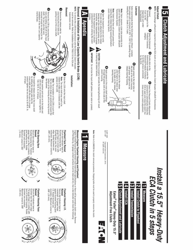
Cross Shaft And BushingsExcessive w
ear at these points can cause side loading on the sleeve bushing, bushing failures and yoke bridge contact w
ith the clutch in the release/open position.
Input ShaftW
ear (roughness) can reduce sleeve bushing life and cause it to becom
e dislodged.
Release YokeW
orn fingers can cause bushingw
ear and yoke interference when
the Electronic Clutch Actuator is at the released position.
Input Shaft SplinesAny w
ear on the splines will prevent
the driven discs from sliding freely,
causing poor clutch release (clutch drag). Slide discs full length of shaft to check for tw
isted shaft splines.Low
Capacity Inertia Brake (LCIB)Eaton requires that you replace the LCIB w
hen replacing the clutch. See Appendix A for LCIB rem
oval and installation instructions.
Check Transmission For W
earReplace any w
orn components.
3 Warning: Do not unbolt the interm
ediate plate from the cover assem
bly.
Progressively tighten mounting bolts in a
crisscross pattern starting with the low
er left bolt. Torque to 40–50 lbs. ft. (54–68 N•m
). Failure to do this could result in im
proper piloting of the clutch and cause clutch dam
age.
5
Slide the clutch assembly over the guide
studs and install six lock washers and
mounting bolts (7/16"x14 UNC x 2 1/4"
grade 5) finger tight. Replace studs with
remaining tw
o lock washers and bolts.
4
2
Insert aligning tool through bearing.1
1
3
4
5
6
7
8
2
Install second disc onto aligning tool. Follow the
orientation instructions on the disc.Install two 7/6" x 14 UNC x
5" studs into upper m
ounting holes. Install assem
bled clutch.
3
8Position the release bearing so the orientation of the lube fitting is in the 4 O'clock position.
Remove the
aligning tool.7
Remove four yellow
shipping bolts in an even 1/4 turn crisscross pattern.
6
NOTE: The ECA Clutch alignment tool is a 14 tooth shaft and is
1-3/4" longer than the standard shaft.
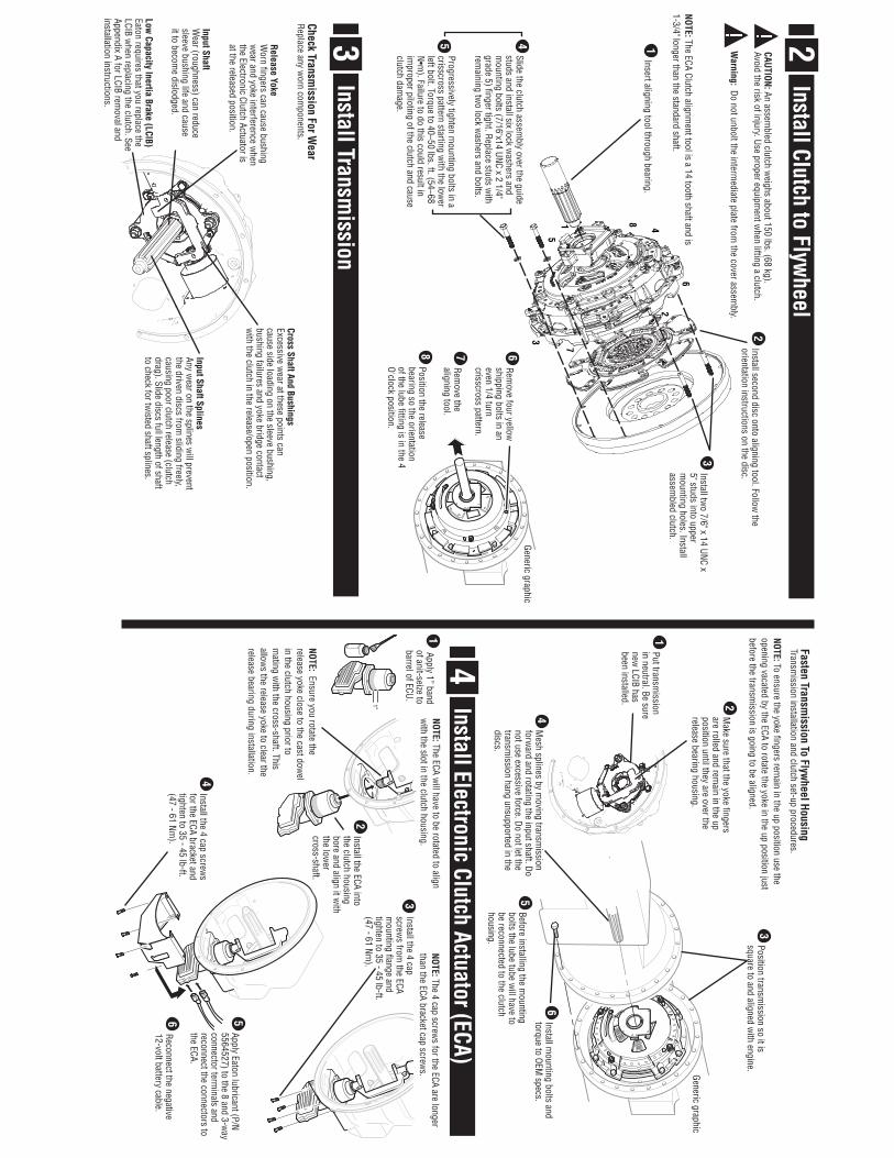
1Put transm
ission in neutral. Be sure new
LCIB has been installed.
3Position transm
ission so it is square to and aligned w
ith engine.
4M
esh splines by moving transm
ission forw
ard and rotating the input shaft. Do not use excessive force. Do not let the transm
ission hang unsupported in the discs.
6Install m
ounting bolts and torque to OEM
specs.
2M
ake sure that the yoke fingers are rolled and rem
ain in the up position until they are over the release bearing housing.
5Before installing the m
ounting bolts the lube tube w
ill have to be reconnected to the clutch housing.
NOTE: To ensure the yoke fingers remain in the up position use the
opening vacated by the ECA to rotate the yoke in the up position just before the transm
ission is going to be aligned.
Install Electronic Clutch Actuator (ECA)4
2Install the ECA into the clutch housing bore and align it w
ith the low
er cross-shaft.
3Install the 4 cap screw
s from the ECA
mounting flange and
tighten to 35 - 45 lb-ft. (47 - 61 Nm
).
4Install the 4 cap screw
s for the ECA bracket and tighten to 35 - 45 lb-ft. (47 - 61 Nm
).
5Apply Eaton lubricant (P/N 5564527) to the 8 and 3-w
ay connector term
inals and reconnect the connectors to the ECA.
6Reconnect the negative 12-volt battery cable.
NOTE: The ECA will have to be rotated to align
with the slot in the clutch housing.
NOTE: Ensure you rotate the release yoke close to the cast dow
el in the clutch housing prior to m
ating with the cross-shaft. This
allows the release yoke to clear the
release bearing during installation.
NOTE: The 4 cap screws for the ECA are longer
than the ECA bracket cap screws.
1 Apply 1” band of anit-seize to barrel of ECU.
1"
Generic graphic
Generic graphic