Embed Size (px)
Citation preview
IEEE TRANSACTIONS ON INSTRUMENTATION AND MEASUREMENT. VOL. 41. NO. 2. APRIL 1992 291
EM1 Shielding Measurements of Conductive Polymer Blends
Nick F. Colaneri and Lawrence W. Shacklette
Abstraet-Shielding efficiencies for a number of blends con- taining a variety of conductive fillers including intrinsically conductive polymers have been measured in the near-field with a dual-chamber box and in the far-field with a transmission line fixture. Although all samples tested satisfied the classical good- conductor approximation, most of them exhibited a crossover from being electrically thin (thickness < skin depth) to being electrically thick (thickness > skin depth) over the frequency range of interest, 1 MHz to 3 GHz. The theoretical relations for both near-field and far-field shielding which are prevalent in the literature do not accurately describe this region of cross- over. We have derived expressions which describe the behavior accurately over the entire range of interest. Far-field shielding emciencies as high as 70 dB at 1 GHz were measured for purely organic composites consisting of an intrinsically conductive polymer, polyaniline, dispersed in a thermoplastic matrix.
I. INTRODUCTION HE shielding effectiveness (SE) of a material is de- T fined as the ratio of transmitted power to incident
power. Hence, for SE measured in decibels (dB) it is given by :
SE = 10 log (?), where Pi is the incident power, and P, is the transmitted power. Because the time averaged power carried by an electromagnetic wave is proportional to the square of the rms electric field strength, SE can also be written as:
SE = 20 log (?), where Ei is the incident rms field strength, and E, is the transmitted rms field strength. It is estimated that to meet FCC Class B requirements for commercial applications, materials with a shielding effectiveness greater than about 40 dB should be adequate for use in electronics housings. Requirements for military applications are significantly higher, in the range between 80 dB and 100 dB. We em- phasize, however, that these numbers can only be used as guides for the selection and/or screening of candidate ma- terials. Final determination still requires fabrication and field testing of individual devices and housing combina- tions.
Manuscript received May 14, 1991; revised November 22, 1991. The authors are with Allied-Signal, Inc., Research and Technology,
IEEE Log Number 9106703. Monistown, NJ 07962.
Two different radiation regimes need to be distin- guished in discussing shielding problems: the near-field and the far-field (or plane wave). When the distance from source to shield is less than about one-sixth the free-space wavelength of the radiation to be shielded, the radiation is dominated by the lower multipole components of the source fields, and is said to be in the near-field limit. In this limit, the electric and magnetic fields can be effec- tively decoupled, so that we may focus on the distinct behavior of high and low impedance waves (the imped- ance of the wave is defined as the ratio of its electric field strength E to its magnetic field strength H). Long straight wires carrying high frequency currents give rise to pre- dominantly electric dipole radiation (high impedance waves), while the same currents in small circular wire loops emit predominantly magnetic dipole radiation (low impedance waves). The separable characteristics of these two types of radiation merge as the source-to-shield dis- tance increases (or, equivalently, as the source frequency increases). The far-field limit is determined by the con- dition that the source-to-shield distance be greater than the free-space wavelength. In this limit, independent of the detailed geometry of the source, the radiation is well- .approximated by plane waves, and its impedance is given by the impedance of free space, 2, = [ p , / ~ , l ” ~ = 377 a, where p, = 47r X lo-’ H/m is the permeability of free space, and E , = 107/(4nc2) F / m is the permittivity of free space (where c = 2.998 X 108.m/s is the velocity of light).
In this report we will apply theoretically derived rela- tions for far-field and. near-field shielding to the measured performance of thermoplastic blends which contain uni- formly dispersed conductive fillers. Our blends are com- posed of a matrix polymer, either polyvinyl chloride (PVC) or nylon, compounded with an inherently con- ducting polymer (ICP), which in these experiments is polyaniline. Such ICP’s, depending on the particular choice of polymer, can have conductivities in the range from 1 to lo5 S/cm [ l ] . Previous tests of ICP’s for EM1 shielding have shown promise, but prospects for appli- cations were limited by problems with environmental sta- bility and by the fact that the conductive polymers were not melt-processible in their conductive form [2]. Our melt-processible thermoplastic blends of PVC and poly- aniline have conductivities as high as 20 S/cm. Conduc- tivities in this range, which are an order of magnitude higher than those that can be obtained with carbon black,
0018-9456/92$03.00 0 1992 IEEE
292 lEEE TRANSACTIONS ON INSTRUMENTATION AND MEASUREMENT. VOL. 41. NO. 2. APRIL 1992
are sufficient to provide a high level of shielding peform- ance ( >> 40 dB). Transmission electron microscopy of thin sections and scanning electron microscopy of fracture surfaces reveal that a significant proportion of the poly- aniline in the blend is dispersed as very fine roughly spherical particles with a diameter in the range, 50-200 nm. These fine particles chain together to provide con- ductive links between the larger polyaniline particles, and thereby give a relatively uniform conductivity, especially when compared with metal-fiber-filled composites. Mold- ings of the polyaniline blends do not have the insulating surface skin which is characteristic of metal-flake or con- ductive-fiber-filled samples.
11. FAR-FIELD SHIELDING: THEORY The calculation of the EM1 shielding of plane electro-
magnetic radiation by a homogeneous conducting sheet of thickness, d, and conductivity, U , is a straightforward, if tedious, exercise in classical electromagnetic theory. This problem has been previously attacked through the use of a two-wire transmission in analogy. The expressions re- sulting from this approach are cumbersome and are use- fully approximated only for the case of thick shields [3]. Rather than using this approach we assume that the radia- tion falls on the sheet at normal incidence, and we write the electric field strength of the incident wave as:
7 (3) where k = 2r /X is the radiation wave vector, w = 2?rf = ck is its angular frequency, z is the distance measured from the surface of the sheet, and c is the time. We then apply the boundary conditions for reflection and trans- mission of the wave at each of the surfaces of the sheet, and derive an expression for the shielding by calculating the ratio of the amplitude of the transmitted field strength to that of the incident field strength, inserting the result into (2). The final expression is considerably simplified by making the classical “good conductor” approxima- tion, by assuming that U / W E , >> 0. For our purposes, this is an extremely good approximation throughout the frequency range of interest. For example, even if U is as low as 0.1 S/cm, then at a frequency of 1 GHz, U. /WE, is still of order lo2. Using this approximation, the far-field EM1 shielding as a function of U , U, and d is given by:
E = Elel(k-Uf)
SE = 10 log (! 4 [ (“) 2W€, [cosh ( y ) - COS (?)I + 2 J z 2WE, [si& ( y ) + sin (:)I + 2 [cosh ( y ) + cos (:)]I).
where
PO
(4)
is the “skin depth” of the conductor. The skin depth is a measure of the depth to which the radiation will penetrate within the material (with a decrease in intensity to 1 / e of its original strength).
For the materials examined in this report, the bulk con- ductivity is in the range 0.1 S/cm-10 S/cm. Under these circumstances, expression (4) has two limits of interest at megahertz to gigahertz frequencies. These limits can be taken as acceptable approximations to (4), depending on whether the frequency is higher or lower than that at which the thickness, d , equals the skin depth, 6. The crossover frequency, wc, at which d = 6 is determined from ( 5 ) :
2 0, = ~
upo d 2 ‘
For frequencies much lower than w, (the case of an “elec- trically thin” shield, d << 6), (4) becomes independent of frequency and reduces to:
/ r r \
SE = 20 log (1 + Z,U d/2) = 20 log 1 + - . (7) :is) where we have cast the expression alternatively in terms of the bulk conductivity, U , and the surface resistivity, R, = l / (ud) . At low frequencies, this expression provides a means of calculating the sample’s bulk ac conductivity from the measured value of its shield. From (7), U = (2/dZ,)(10SE/20 - 1).
For frequencies much above U, (i.e., when the thick- ness of the sheet greatly exceeds the skin depth, d >> 6), (4) reduces to the limiting form:
The first term on the right of this expression is the con- tribution to the shielding due to single reflections to the incident wave by the front and back surfaces of the sheet. The second term represents the attenuation by absorption as the wave passes through the sheet.’ At high frequencies (greater than about 2 4 , the second term dominates the first, and the shielding increases monotonically with fre- quency.
111. FAR-FIELD SHIELDING: MEASUREMENTS
To measure the EM1 shielding effectiveness of a sheet of conducting material in the far-field limit, in principle one need only interpose the test material between a source of plane waves and an appropriate detector. An ingenious method capable of testing small samples was developed at the Battelle National Laboratory in the late 1970’s [4]. It is based on the fact that inside a waveguide, the TEMm mode propagates as a series of plane wave fronts. The patented Battelle test cell design uses a waveguide con- sisting of a pair of coaxial cylinders, and therefore re- quires that samples be machined in the shape of an an- nulus. The inner and outer diameter surfaces of the samples were coated with silver paint to ensure good elec-
COLANERI AND SHACKLETTE: EM1 SHIELDING MEASUREMENTS
20
2') 3
-
trical contact. This procedure was found to be critical to obtain good data. The measurements reported here were made by us using a coaxial test cell provided by USTEK, Inc. in conjunction with a Hewlett-Packard HP 8753A network analyzer and HP85046A/B S-parameter test set. The test cell accommodates an annular sample of outer diameter 10 cm with a 4-cm diameter concentric hole. The samples were typically of order 3.2 mm thick.
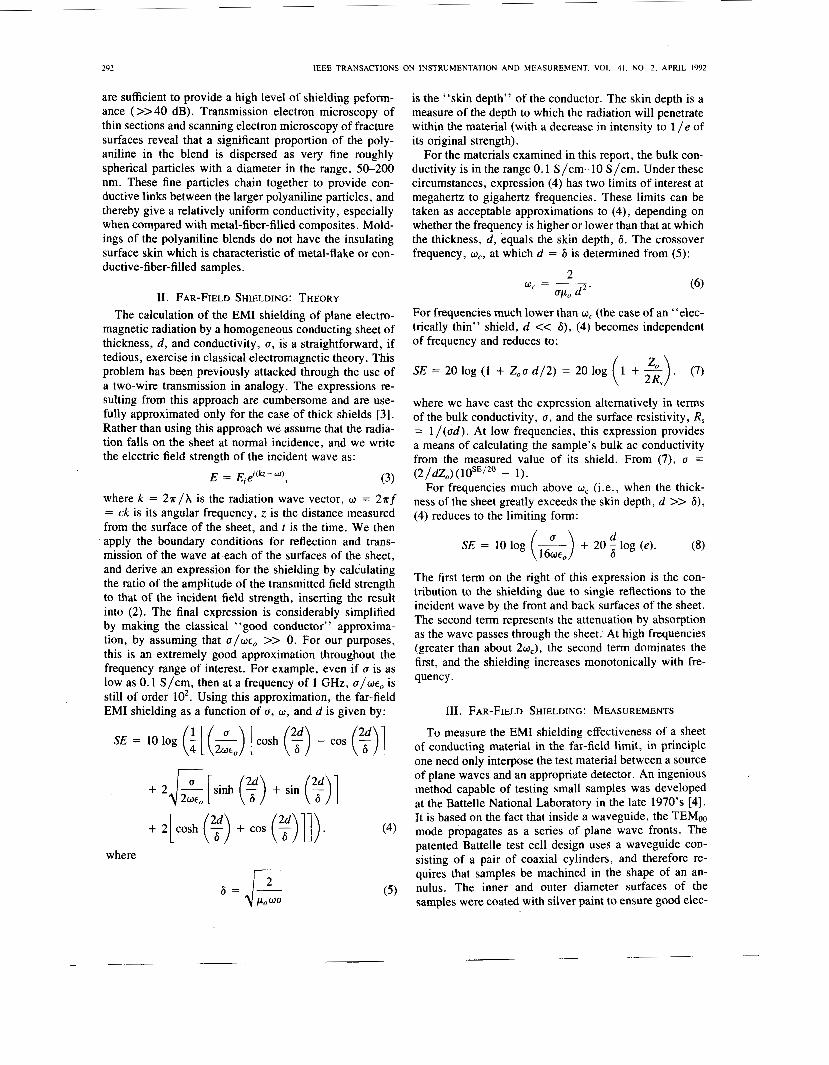
We measured the far-field shielding of a number of samples of conductive blends, representing composites with bulk conductivities between 0.1 S/cm and 10 S/cm. The far-field shielding effectiveness data for four of the samples with representative bulk conductivity values are shown in Fig. 1 where they are compared with the per- formance of the stainless-fiber-filled sample. These data show the behavior anticipated above in our theoretical discussion: the shielding effectiveness is frequency inde- pendent up to some limiting frequency (uc), after which it increases with increasing frequency. Equation (7) can be used to determine a value for a sample's bulk conduc- tivity from its low frequency shielding data (i.e., at fre- quencies less than about 10 MHz for our blends). The results of such calculations are compared in Table I with dc conductivity measurements made by two different methods, 4-in-line [ 5 ] , [6] and van der Pauw [7]. Al- though any given measurement has a precision of f5%, and theoretically both dc methods should give the same result for samples with uniform conductivity, the results are expected to differ for samples which have a lower con- ductivity near the surface or other nonuniformities in the conductivity. The 4-in-line measurement, which em- ployed a probe spacing of 1 mm, is expected to give added weight to the conductivity near the surface, where the van der Pauw will give a more uniformly weighted average. The agreement between the bulk conductivity determined from the shielding data and that measured by the conven- tional dc methods is good in all but one case. It was very difficult to make electrical contact with a small probe to the stainless steel fiber sample, rendering a conductivity determination by the 4-in-line method impossible. The sample evidently possessed a gross inhomogeneity in the distribution of fibers between the surface and the bulk.
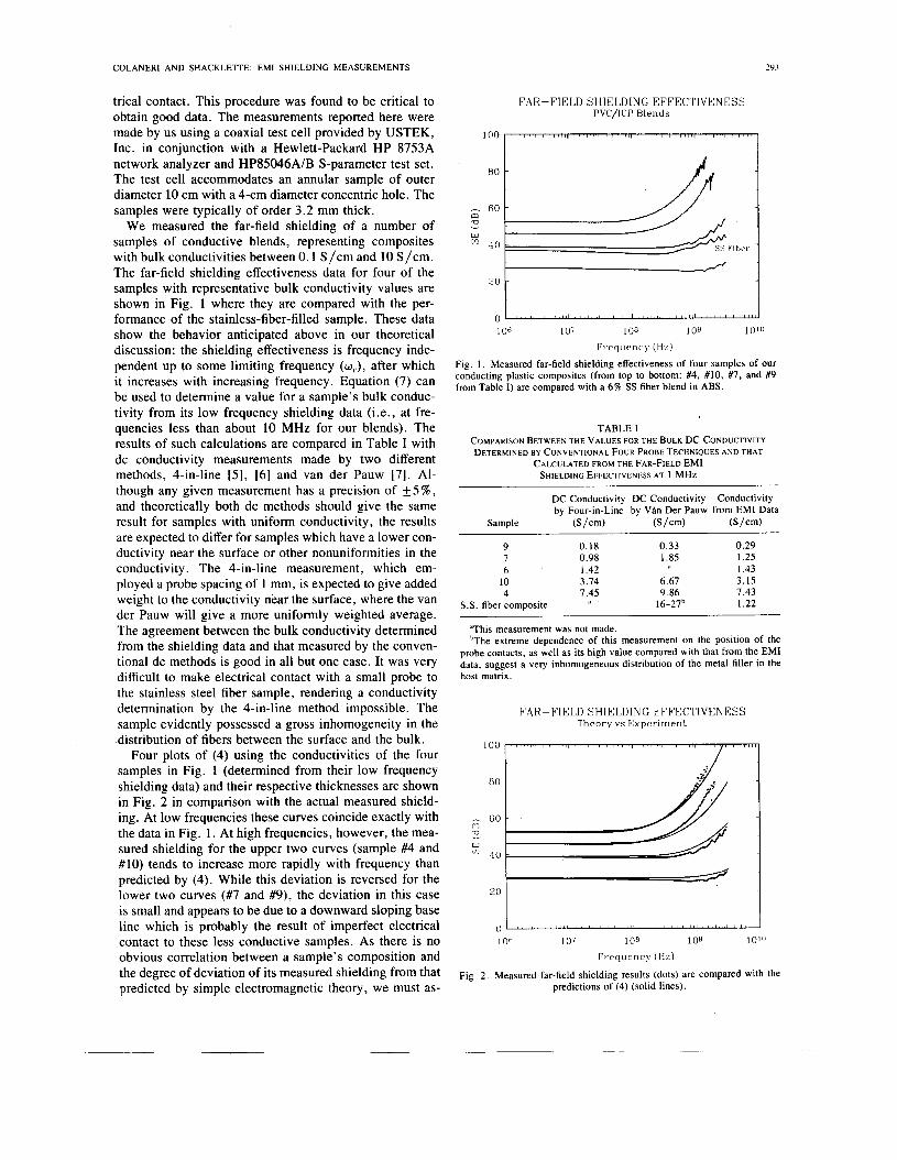
Four plots of (4) using the conductivities of the four samples in Fig. 1 (determined from their low frequency shielding data) and their respective thicknesses are shown in Fig. 2 in comparison with the actual measured shield- ing. At low frequencies these curves coincide exactly with the data in Fig. 1. At high frequencies, however, the mea- sured shielding for the upper two curves (sample #4 and #lo) tends to increase more rapidly with frequency than predicted by (4). While this deviation is reversed for the lower two curves (#7 and #9), the deviation in this case is small and appears to be due to a downward sloping base line which is probably the result of imperfect electrical contact to these less conductive samples. As there is no obvious correlation between a sample's composition and the degree of deviation of its measured shielding from that predicted by simple electromagnetic theory, we must as-
FAR-FIELD SHIELDING EFFECTIVENESS PVC/ICP Blends
TABLE I COMPARISON BETWEEN THE VALUES FOR THE BULK DC CONDUCTIVITY DETERMINED BY CONVENTIONAL FOUR PROBE TECHNIQUES A N D THAT
CALCULATED FROM THE FAR-FIELD EM1 SHIELDING EFFECTIVENESS AT 1 MHZ
DC Conductivity DC Conductivity Conductivity by Four-in-Line by Van Der Pauw from EM1 Data
Sample (S/cm) (S/cm) (S /cm)
9 0 .18 0 . 3 3 0 . 2 9 0 . 9 8 1.85 1.25
I .43 I 6 I .42
10 3.14 6.67 3.15 7 .45 9.86 7.43
16-27b 1.22 4
S.S. fiber composite
"This measurement was not made. hThe extreme dependence o f this measurement on the position o f the
probe contacts, as well as its high value compared with that from the EM1 data, suggest a very inhomogeneous distribution o f the metal filler in the host matrix
FAR-FIELD SHIELDING EFFECTIVENESS Theory v s Exper iment
294 IEEE TRANSACTIONS ON INSTRUMENTATION AND MEASUREMENT, VOL. 41. NO. 2. APRIL 1992
sume this deviation to be a consequence of some aspect of the blending process which influences the population of conductive particles which are electrically connected (percolated).
A deviation in measured shielding effectiveness from that predicted by simple electromagnetic theory can be interpreted as due to a dependence of the sample's bulk conductivity on frequency. In fact, a frequency-depen- dent conductivity is to be expected for a conducting ma- terial randomly dispersed in an insulating matrix, and has been the object of considerable research interest. In par- ticular, there has been a lot of recent work attempting to treat the problem using newly developed techniques of percolation theory [SI-[lo]. For a conducting composite, the theories suggest that above a frequency which depends on the reduced concentration of the conducting compo- nent (i.e., the difference between its concentration and the percolation threshold concentration), the conductivity in- creases as a power of the frequency: U - U" [SI-[ll]. Two different mechanisms are thought to contribute to this frequency dependence: polarization between linked clus- ters of the conducting component [ 121 and anomalous car- rier diffusion within the random clusters [13]. Qualita- tively, it can be understood by thinking of the dispersed conductor in the composite as a random network of resis- tive and capacitive links throughout the sample. The in- crease in conductivity with frequency arises from the in- crease in the capacitive contribution as frequency is increased.
Two principal methods of treating near-field shielding are discussed in the literature. One approach is to assume a specific source geometry and then use Maxwell's equa- tions to calculate explicitly the radiated electromagnetic fields with and without a planar shield in place [14]. The shielding effectiveness is then calculated from the field strengths using (2). This method results in exact, but un- wieldy, expressions for the shielding which must be ap- proximated in some way in order to make a detailed com- parison with experimental measurements [ 151. These expressions are particularly difficult to approximate in the case of electrically thin samples.
A second approach to near-field shielding involves a formal analogy between shielding problems and the the- ory of reflection and transmission of electromagnetic sig- nals at impedance mismatches in transmission lines [3]. In limiting cases where they can be compared, this method gives results which agree with those obtained by the method using the field equations, which was outlined above. The transmission line analogy is, however, much more suitable for our purposes. It is constructed by re- placing free space with a parallel wire transmission line whose impedance is the same as that of the wave to be shielded. In the case of plane waves this impedance is Z, = 377 ohms. For electric dipole radiation the wave impedance can be calculated from the expressions for the fields of a radiating dipole [16]. For source-to-shield dis- tances r much less than the free-space wavelength it is given by
IV. NEAR-FIELD SHIELDING: THEORY 1 kr
z, = -zo. A theoretical discussion of near-field shielding by a
(9)
sheet of conducting material contains more algebraic complications than that for far-field shielding. The nature of the electromagnetic fields incident on the shield, in ad- dition to depending on the source-to-shield distance, de- pends on the geometry of the source. Altering this ge- ometry changes the relative proportions of the different multipole components of the radiation, which changes the dependence of the shielding on the frequency, conductiv- ity, and source-to-shield distance. Also, as in the case of far-field shielding, the thickness of the weakly conducting sheets studied here plays a role.
Fortunately, the study of near-field shielding problems can be greatly simplified by the fact that, except for ex- ceptional source geometries, the fields are dominated by the lowest multipole contributions: electric and magnetic dipole radiation. Megahertz frequency magnetic dipole radiation is expected to be low enough in intensity to be ignored in most practical applications. The situation is
This expression must be used with caution, as the ap- proximation rapidly becomes inadequate for source-to- shield distances approaching one-sixth the wavelength. In the transmission line analogy, the radiation shield is re- placed by a series impedance placed along the transmis- sion line. The barrier impedance is complex and related to the surface impedance of the shield. It is given by
z B - - Z O L w E " ( ~ + i ) . (10)
With these definitions, the shielding effectiveness can again be calculated by working out the reflection and transmission coefficients for signals propagated along the line. The general result is given by
SE = 20 log (q sinh (ad) + cosh (ad) _ _
also simplified for our purposes because, as will be fur- ther discussed in the next section, the techniques used to measure near-field shielding do not permit anything'like the detailed comparison between theory and experiment possible in the far-field case. Our goal in this section,
where = z,/zB, and a = (1 + i ) / 6 is the complex propagation constant.
of far-field shielding, (11) is usually written in the limit of an electrically thick shield (d /6 >, 1 , U >, U c ) . xn this approximation, (11) becomes
in the
therefore, is to describe at least qualitatively the expected . \
frequency dependence of the near-field shielding effec- tiveness.
COLANERI AND SHACKLETTE: EM1 SHIELDING MEASUREMENTS 295
or
where we have used the fact that K >> 1. The first term on the right-hand side is easily interpreted as the shielding due to reflection, and the second as that due to absorption. The shielding from reflection is expected to decrease by 30 dB for each decade increase in the frequency. Of course, the total near-field shielding never gets smaller than the far-field shielding, since as the wavelength be- comes shorter at high frequencies, the near-field shielding approaches the far-field shielding as a limit. A closer comparison of (8) for far-field shielding and (13) for near- field shielding reveals that the expression in (1 3) exceeds that in (8) by a term which equals 20 log [clwr]. This term will be positive as long as c / w r > 1, or equivalently as long r < X/27r. The latter condition is immediately recognized as the condition for the near-field limit. Thus at wavelengths, X < 2nr, (13) loses its validity, and the shielding is described by the far-field expression of (8).
Like the situation for far-field shielding, (11) ap- proaches a limit with a different frequency dependence for electrically thin samples. As most of those samples of in- terest to us are electrically thin at frequencies of only a few megahertz, this limit is important for the interpreta- tion of our shielding data. It can be derived from (1 1) by making the approximation K >> 1, d / 6 << 1, and w << 0,. This gives
SE = 20 log (e Zoa d) = 20 log (G c z o E ) . (14)
In contrast to (13), this expression shows a decrease of 20 dB per decade of increase in the frequency or decade of increase in surface resistance, R, = ( l / ( a d). Without a detailed field calculation, therefore, we can conclude that the near-field shielding effectiveness is (very roughly) ex- pected to decrease by 20-30 dB for each decade increase in the frequency and 10-20 dB for each decade increase in resistance.
V . NEAR-FIELD SHIELDING: MEASUREMENTS
The most straightforward method of measuring the near-field shielding effectiveness of a sheet of material is to place it across an aperture between two shielded enclo- sures. In one enclosure, at a distance less than one-sixth the radiation wavelength, a source of rfradiation is placed. The other contains a receiver to determine the strength of the signal which is transmitted by the material. Typically, the pair of shielded enclosures is of relatively compact dimensions, of order 1 m3.
The chief drawback of this “two-chamber box” mea- surement technique is that the results are quite sensitive to the specific dimensions of the chambers and the aper- ture [ 171. The sensitivity to box dimensions is due to the fact that the normal modes of the source chamber deter-
mine its Q value, which affects the amount of radiation passing through the aperture independent of the SE of the test material. In addition, diffraction effects through the aperture play a role. To eliminate these uncertainties, the American Society for Testing and Materials (ASTM) has adopted a standard test based on a specific box geometry which results in measurements reproducible in different laboratories. The ASTM has also outlined a standard test procedure, consisting of near-field shielding measure- ments at four principle frequencies: 30 MHz, 100 MHz, 300 MHz, and 1 GHz [17], [18].
Near-field shielding measurements of our samples were performed for us by Radiation Sciences, Inc. of Harleys- ville, PA, using the ASTM method. The results of these measurements are presented in Table 11. The most notice- able feature is that the near-field shielding shows the ex- pected monotonic decrease with frequency except for an anomalously high value at 300 MHz. This deviation is a universal feature not only of our data, but of the two- chamber box data for various materials given in the lit- erature as well [17], [19], [20]. We believe that it is an instrumental effect, due to the particular choice of dimen- sions for the ‘‘standard” two-chamber box. Naturally, this problem makes the measured value of the near-field shielding at 300 MHz difficult to interpret. We noted in the dimension above that the value of the near-field shielding is expected to approach (from above) the far- field value at high frequencies. However, in almost all the samples for which we measured the far-field shielding, the shielding measured at 1 GHz was slightly higher than that measured at the same frequency using the two-cham- ber box (Table 11). It seems probable that this shortfall is a consequence of poor electrical contact between the sam- ple and the edges of the aperture inside the two-chamber box. Although such contact is sometimes facilitated by painting the edges of the sample with silver paint before mounting, this was not done for our measurements.
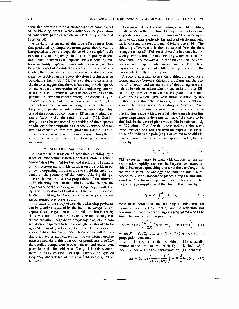
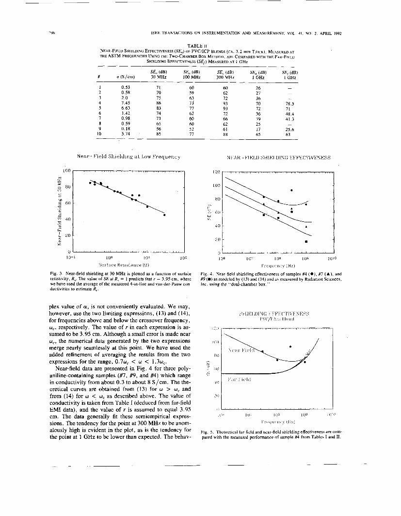
At 30 MHz we are well within the thin sample limit for all ofour blend samples. We can test the validity of (14) at low frequencies by plotting SE at 30 MHz versus R, as shown in Fig. 3. The slope of this measured data, -20.1 (with a standard deviation of 1.0) is indeed very close to that predicted by (14), -20 dB/decade increase in R,. We can determine the effective source-to-shield distance in the dual-chamber box used by Radiation Sciences from the intercept of the plot in Fig. 3 (at R, = 1 Q/sq). We calculate a value, r = 3.95 cm. The experimental setup actually places the source antenna right against the sur- face of the shield, but since there will also be multiple reflections of the source radiation within the box, it is not unreasonable that the effective source-to-shield distance will be slightly larger than the direct antenna-to-shield distance.
We now have in place sufficient tools to put together a semi-empirical expression for predicting the near-field shielding results from the dual-chamber box as a function of a, d , and w . Unlike the far-field case, the exact expres- sion for near-field shielding, (1 l ) , which contains a com-
IEEE TRANSACTIONS ON INSTRUMENTATION AND MEASUREMENT. VOL. 41. NO. 2. APRIL 1992
TABLE 11 NEAR-FIELD SHIELDING EFFECTIVENESS (SE,,) OF PVC/ICP BLENDS (CA. 3.2 mm THICK), MEASURED AT THE ASTM FREQUENCIES USING THE TWO-CHAMBER Box METHOD, A R E COMPARED W I T H THE FAR-FIELD
SHIELDING EFFECTIVENESS (SEf ) MEASURED AT 1 GHz
SE,, (dB) SE,, (dB) SE,, (dB) SE,, (dW SE, (dB) # (S/cm) 30 MHz 100 MHz 300 MHz 1 GHz 1 GHz
1 0.53 2 0.58 3 2.0 4 7.45 5 6.63 6 1.42 7 0.98 8 0.59 9 0.18
10 3.14
71 70 15 86 83 74 13 65 56 85
60 59
2 17 62 60 60 52 77
60 62 72 93 93 72 66 62 61 88
26 27 36 70 72 36 39 25 17 65
~
- -
- 78.5 71 48.4 41.3
25.6 63
-
Near-Field Shielding a t Low Frequency
10-1 100 101 102
S u r f a c e Res is tance (n)
Fig. 3. Near-field shielding at 30 MHz is plotted as a function of surface resistivity, R,. The value of SE at R, = 1 predicts that r = 3.95 cm, where we have used the average of the measured 4-in-line and van-der-Pauw con- ductivities to estimate R,.
plex value of a, is not conveniently evaluated. We may, however, use the two limiting expressions, (13) and (14), for frequencies above and below the crossover frequency, wc, respectively. The value of r in each expression is as- sumed to be 3.95 cm. Although a small error is made near cor, the numerical data- generated by the two expressions merge nearly seamlessly at this point. We have used the added refinement of averaging the results from the two expressions for the range, 0 . 7 ~ ~ < w < 1 . 3 ~ ~ .
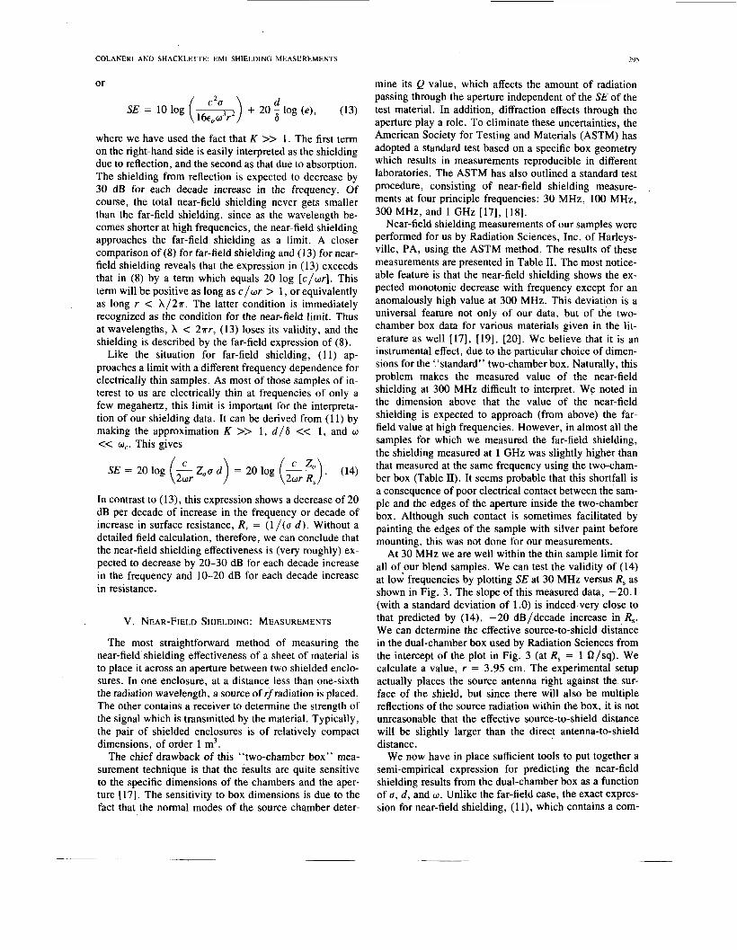
Near-field data are presented in Fig. 4 for three poly- aniline-containing samples (#7, #9, and #4) which range in conductivity from about 0.3 to about 8 S/cm. The the- oretical curves are obtained from (1 3) for w > w, and from (14) for w < w, as described above. The value of conductivity is taken from Table I (deduced from far-field EM1 data), and the value of r is assumed to equal 3.95 cm. The data generally fit these semiempirical expres- sions. The tendency for the point at 300 MHz to be anom- alously high is evident in the plot, as is the tendency for the point at 1 GHz to be lower than expected. The behav-
NEAR-FIELD SHIELDING EFFECTIVENESS
100 ~
80 ~ - m U
W cn - 60
4 0 ~
E O 1 1 0 106 107 108 109 10'0
F r e q u e n c \ (Hz)
Fig. 4. Near-field shielding effectiveness of samples #4 ( O ) , #7 (A), and #9 (H) as modeled by (13) and (14) and as measured by Radiation Sciences, Inc. using the "dual-chamber box."
I (I(' io; IO6 I 0 9
1 I c ( ~ l l t ' I l C ' \ ( l i z )
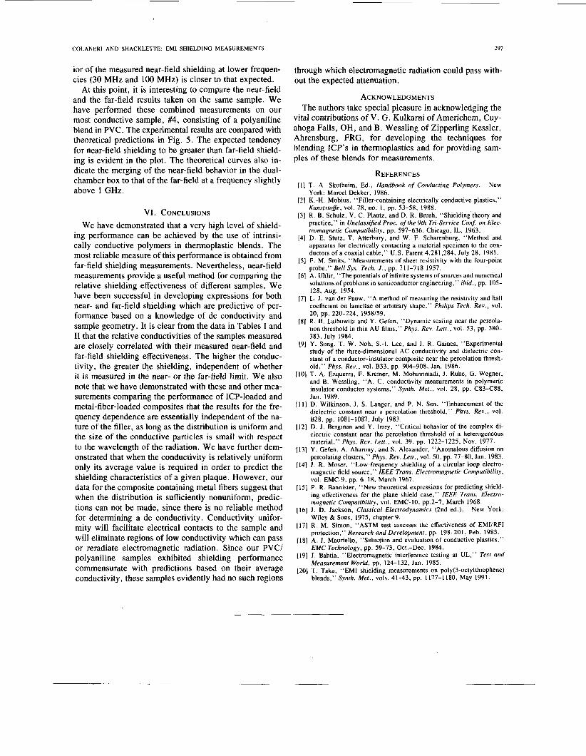
Fig. 5. Theoretical far-field and near-field shielding effectiveness are com- pared with the measured performance of sample #4 from Tables I and 11.
COLANERl AND SHACKLETTE: EM1 SHlELDING MEASUREMENTS
ior of the measured near-field shielding at lower frequen- cies (30 MHz and 100 MHz) is closer to that expected.
At this point, it is interesting to compare the near-field and the far-field results taken on the same sample. We have performed these combined measurements on our most conductive sample, #4, consisting of a polyaniline blend in PVC. The experimental results are compared with theoretical predictions in Fig. 5 . The expected tendency for near-field shielding to be greater than far-field shield- ing is evident in the plot. The theoretical curves also in- dicate the merging of the near-field behavior in the dual- chamber box to that of the far-field at a frequency slightly above 1 GHz.
VI. CONCLUSIONS We have demonstrated that a very high level of shield-
ing performance can be achieved by the use of intrinsi- cally conductive polymers in thermoplastic blends. The most reliable measure of this performance is obtained from far-field shielding measurements. Nevertheless, near-field measurements provide a useful method for comparing the relative shielding effectiveness of different samples. We have been successful in developing expressions for both near- and far-field shielding which are predictive of per- formance based on a knowledge of dc conductivity and sample geometry. It is clear from the data in Tables I and I1 that the relative conductivities of the samples measured are closely correlated with their measured near-field and far-field shielding effectiveness. The higher the conduc- tivity, the greater the shielding, independent of whether it is measured in the near- or the far-field limit. We also note that we have demonstrated with these and other mea- surements comparing the performance of ICP-loaded and metal-fiber-loaded composites that the results for the fre- quency dependence are essentially independent of the na- ture of the filler, as long as the distribution is uniform and the size of the conductive particles is small with respect to the wavelength of the radiation. We have further dem- onstrated that when the conductivity is relatively uniform only its average value is required in order to predict the shielding characteristics of a given plaque. However, our data for the composite containing metal fibers suggest that when the distribution is sufficiently nonuniform, predic- tions can not be made, since there is no reliable method for determining a dc conductivity. Conductivity unifor- mity will facilitate electrical contacts to the sample and will eliminate regions of low conductivity which can pass or reradiate electromagnetic radiation. Since our PVC/ polyaniline samples exhibited shielding performance commensurate with predictions based on their average conductivity, these samples evidently had no such regions
297
through which electromagnetic radiation could pass with- out the expected attenuation.
ACKNOWLEDGMENTS The authors take special pleasure in acknowledging the
vital contributions of V. G. Kulkami of Americhem, Cuy- ahoga Falls, OH, and B. Wessling of Zipperling Kessler, Ahrensburg, FRG, for developing the techniques for blending ICP’s in thermoplastics and for providing sam- ples of these blends for measurements.
REFERENCES T. A. Skotheim, Ed., Handbook of Conducting Polymers. New York: Marcel Dekker, 1986. K.-H. Mobius, “Filler-containing electrically conductive plastics,” Kunststofle, vol. 78, no. 1, pp. 53-58, 1988. R. B. Schulz, V. C. Plantz, and D. R. Brush, “Shielding theory and practice,” in Unclassified Proc. of the 9th Tri-Service Conf. on Elec- tromagnetic Compatibility, pp. 597-636, Chicago, IL, 1963. D. E. Stutz, T. Atterbury, and W. F. Scharenburg, “Method and apparatus for electrically contacting a material specimen to the con- ductors of a coaxial cable,” U.S. Patent 4,281,284, July 28, 1981. F. M. Smits, “Measurements of sheet resistivity with the four-point probe,” BellSys. Tech. J . , pp. 711-718 1957. A. Uhlir, “The potentials of infinite systems of sources and numerical solutions of problems in semiconductor engineering,” ibid., pp. 105- 128, Aug. 1954. L. J. van der Pauw, “A method of measuring the resistivity and hall coefficient on lamellae of arbitrary shape,” Phifips Tech. Rev., vol.
R. B. Laibowitz and Y. Gefen, “Dynamic scaling near the percola- tion threshold in thin AU films,’’ Phys. Rev. Lett., vol. 53, pp. 380- 383, July 1984. Y. Song, T. W. Noh, S . 4 . Lee, and J . R. Gaines, “Experimental study of the three-dimensional AC conductivity and dielectric con- stant of a conductor-insulator composite near the percolation thresh- old,” Phys. Rev., vol. B33, pp. 904-908, Jan. 1986. T. A. Ezquerra, F. Kremer, M. Mohammadi, 1. Ruhe, G. Wegner, and B. Wessling, “A. C. conductivity measurements in polymeric insulator conductor systems,’’ Synth. Met., vol. 28, pp. C83-C88, Jan. 1989.
20, pp. 220-224, 1958/59.
1111 D. Wilkinson, J. S . Langer, and P. N. Sen, “Enhancement of the dielectric constant near a oercolation threshold,” Phys. Rev., vol. 828, pp. 1081-1087, J U I ~ i983. D. J. Bergman and Y. Imry, “Critical behavior of the complex di- electric constant near the percolation threshold of a heterogeneous material,” Phys. Rev. Lett., vol. 39, pp. 1222-1225, Nov. 1977. Y. Gefen, A. Aharony, and S. Alexander, “Anomalous diffusion on percolating clusters,” Phys. Rev. Lett., vol. 50, pp. 77-80, Jan. 1983. 1. R. Moser, “Low-frequency shielding of a circular loop electro- magnetic field source,” IEEE Trans. Electromagnetic Compatibility, vol. EMC-9, pp. 6-18, March 1967. P. R. Bannister, “New theoretical expressions for predicting shield- ing effectiveness for the plane shield case,” lEEE Trans. Elecrro- magnetic Compatibility, vol. EMC-IO, pp.2-7, March 1968. 1. D. Jackson, Classical Electrodynamics (2nd ed.). New York: Wiley & Sons, 1975, chapter 9. R. M. Simon, “ASTM test assesses the effectiveness of EMURFI protection,” Research and Development, pp. 198-201, Feb. 1985. A. 1. Mauriello, “Selection and evaluation of conductive plastics,” EMC Technology, pp. 59-73, Oct.-Dec. 1984. J. Bahtia, “Electromagnetic interference testing at UL,” Test and Measurement World, pp. 124-132, Jan. 1985. T. Taka, “EM1 shielding measurements on poly(3-octylthiophene) blends,” Synrh. Met., vols. 41-43, pp. 1177-1180, May 1991.


![Electromagnetic Shielding Characterization of Conductive ...jpier.org/PIERM/pierm56/04.17011305.pdfpermeability [6], but it is expensive, heavy and not flexible at all. Coating the](https://img.pdfslide.net/doc/110x75/5f10aa237e708231d44a37fa/electromagnetic-shielding-characterization-of-conductive-jpierorgpiermpierm5604.jpg)