Embed Size (px)
Citation preview
ETSI EN 300 386 V1.6.1 (2012-09)
Electromagnetic compatibility and Radio spectrum Matters (ERM);
Telecommunication network equipment; ElectroMagnetic Compatibility (EMC) requirements
Harmonized European Standard
ETSI
ETSI EN 300 386 V1.6.1 (2012-09) 2
Reference REN/ERM-EMC-312
Keywords EMC, network, testing
ETSI
650 Route des Lucioles F-06921 Sophia Antipolis Cedex - FRANCE
Tel.: +33 4 92 94 42 00 Fax: +33 4 93 65 47 16
Siret N° 348 623 562 00017 - NAF 742 C
Association à but non lucratif enregistrée à la Sous-Préfecture de Grasse (06) N° 7803/88
Important notice
Individual copies of the present document can be downloaded from: http://www.etsi.org
The present document may be made available in more than one electronic version or in print. In any case of existing or perceived difference in contents between such versions, the reference version is the Portable Document Format (PDF).
In case of dispute, the reference shall be the printing on ETSI printers of the PDF version kept on a specific network drive within ETSI Secretariat.
Users of the present document should be aware that the document may be subject to revision or change of status. Information on the current status of this and other ETSI documents is available at
http://portal.etsi.org/tb/status/status.asp
If you find errors in the present document, please send your comment to one of the following services: http://portal.etsi.org/chaircor/ETSI_support.asp
Copyright Notification
No part may be reproduced except as authorized by written permission. The copyright and the foregoing restriction extend to reproduction in all media.
© European Telecommunications Standards Institute 2012.
All rights reserved.
DECTTM, PLUGTESTSTM, UMTSTM and the ETSI logo are Trade Marks of ETSI registered for the benefit of its Members. 3GPPTM and LTE™ are Trade Marks of ETSI registered for the benefit of its Members and
of the 3GPP Organizational Partners. GSM® and the GSM logo are Trade Marks registered and owned by the GSM Association.
ETSI
ETSI EN 300 386 V1.6.1 (2012-09) 3
Contents
Intellectual Property Rights ................................................................................................................................ 6
Foreword ............................................................................................................................................................. 6
1 Scope ........................................................................................................................................................ 7
2 References ................................................................................................................................................ 8
2.1 Normative references ......................................................................................................................................... 8
2.2 Informative references ...................................................................................................................................... 10
3 Definitions and abbreviations ................................................................................................................. 12
3.1 Definitions ........................................................................................................................................................ 12
3.2 Abbreviations ................................................................................................................................................... 14
4 Installation environment ......................................................................................................................... 14
5 Immunity: test methods .......................................................................................................................... 15
5.1 Electrostatic discharge ...................................................................................................................................... 15
5.2 Electrical fast transients/burst ........................................................................................................................... 15
5.3 Surges ............................................................................................................................................................... 15
5.3.1 Signal line ports .......................................................................................................................................... 15
5.3.2 AC power ports ........................................................................................................................................... 15
5.4 Immunity to continuous conducted signals ...................................................................................................... 16
5.4.1 Low frequency (≤ 150 kHz) ........................................................................................................................ 16
5.4.2 Radio frequency (> 150 kHz) ..................................................................................................................... 16
5.4.2.1 AC power port ....................................................................................................................................... 16
5.4.2.2 DC power port ....................................................................................................................................... 16
5.4.2.3 Signal line port ...................................................................................................................................... 16
5.5 Immunity to radiated electromagnetic fields .................................................................................................... 16
5.6 Immunity to power supply disturbances: AC and DC power ports .................................................................. 16
5.6.1 Test of immunity to low frequency disturbances: AC power ports ............................................................ 16
5.6.2 Test of immunity to low frequency disturbances: DC power ports ............................................................ 16
6 Emission: test methods ........................................................................................................................... 17
6.1 AC power port .................................................................................................................................................. 17
6.2 DC power port .................................................................................................................................................. 17
6.3 Telecommunication Port .................................................................................................................................. 17
6.4 Radiated emission............................................................................................................................................. 17
7 Test levels and limits .............................................................................................................................. 18
7.1 Emission ........................................................................................................................................................... 18
7.1.1 Enclosure port, Radiated electromagnetic field emissions .......................................................................... 18
7.1.2 AC ports ...................................................................................................................................................... 18
7.1.2.1 Conducted emissions ............................................................................................................................. 18
7.1.2.2 Current harmonics ................................................................................................................................. 18
7.1.2.3 Voltage fluctuations .............................................................................................................................. 18
7.1.3 DC ports, Conducted emissions .................................................................................................................. 18
7.1.4 Telecommunication ports, Conducted emissions ........................................................................................ 18
7.2 Immunity .......................................................................................................................................................... 19
7.2.1 Equipment operating in telecommunication centres ................................................................................... 19
7.2.1.1 Telecommunication centres, enclosure port .......................................................................................... 19
7.2.1.2 Telecommunication centres, ports for outdoor signal lines ................................................................... 20
7.2.1.3 Telecommunication centres, ports for indoor signal lines ..................................................................... 21
7.2.1.4 Telecommunication centres, AC power ports ....................................................................................... 22
7.2.1.5 Telecommunication centres, DC power ports ....................................................................................... 22
7.2.2 Equipment operating in locations other than telecommunication centres ................................................... 23
7.2.2.1 Other than telecommunication centres, enclosure port ......................................................................... 23
7.2.2.2 Other than telecommunication centres, ports for outdoor signal lines .................................................. 24
7.2.2.3 Other than telecommunication centres, ports for indoor signal lines .................................................... 25
7.2.2.4 Other than telecommunication centres, AC power ports ....................................................................... 26
ETSI
ETSI EN 300 386 V1.6.1 (2012-09) 4
7.2.2.5 Other than telecommunication centres, DC power ports ....................................................................... 27
8 General test configuration ...................................................................................................................... 28
9 General operational conditions during testing ........................................................................................ 28
9.1 Equipment configuration .................................................................................................................................. 28
9.2 Operation of multimedia network equipment ................................................................................................... 29
10 General immunity conditions ................................................................................................................. 29
10.1 General performance criteria ............................................................................................................................ 29
11 Switching equipment specific requirements ........................................................................................... 30
11.1 Test configuration............................................................................................................................................. 30
11.2 Operational conditions ..................................................................................................................................... 31
11.2.1 Emission ..................................................................................................................................................... 32
11.2.2 Immunity .................................................................................................................................................... 32
11.3 Specific immunity performance criteria ........................................................................................................... 32
11.3.1 Digital port performance criteria ................................................................................................................ 32
11.3.1.1 Performance criterion A (continuous phenomena) ................................................................................ 32
11.3.1.2 Performance criterion B (transient phenomena).................................................................................... 32
11.3.1.3 Performance criterion C (interruptions) ................................................................................................ 32
11.3.2 Analogue port performance criteria ............................................................................................................ 33
11.3.2.1 Performance criterion A (continuous phenomena) ................................................................................ 33
11.3.2.2 Performance criterion B (transient phenomena).................................................................................... 33
11.3.2.3 Performance criterion C (interruptions) ................................................................................................ 33
12 Transmission equipment specific requirements ..................................................................................... 33
12.1 Test configuration............................................................................................................................................. 33
12.2 Operational conditions ..................................................................................................................................... 34
12.2.1 Emission ..................................................................................................................................................... 34
12.2.2 Immunity .................................................................................................................................................... 34
12.3 Specific immunity performance criteria ........................................................................................................... 34
12.3.1 Digital signal ports ...................................................................................................................................... 34
12.3.1.1 Performance criterion A (continuous phenomena) ................................................................................ 35
12.3.1.2 Performance criterion B (transient phenomena).................................................................................... 35
12.3.1.3 Performance criterion C (interruptions) ................................................................................................ 35
12.3.2 Analogue voice frequency signal ports ....................................................................................................... 35
12.3.2.1 Performance criterion A (continuous phenomena) ................................................................................ 35
12.3.2.2 Performance criterion B (transient phenomena).................................................................................... 35
12.3.3 SDH and PDH interfaces ............................................................................................................................ 35
12.3.3.1 Tributary and aggregate interfaces ........................................................................................................ 35
12.3.4 ISDN interfaces .......................................................................................................................................... 36
12.3.4.1 Primary rate access ISDN interfaces ..................................................................................................... 36
12.3.4.2 Network termination NT1 for ISDN "U" interfaces .............................................................................. 36
12.3.4.3 Basic access ISDN interfaces ................................................................................................................ 36
12.3.5 Analogue interfaces .................................................................................................................................... 36
12.3.5.1 Trunk interfaces and leased line interfaces ........................................................................................... 36
12.3.5.2 Subscriber interfaces ............................................................................................................................. 36
12.3.6 V.10, V.11, V.24, V.28, V.36, X.24 and similar V.- and X.- series interfaces ........................................... 36
12.3.7 Ethernet and packet-data interfaces ............................................................................................................ 36
12.3.7.1 Performance criterion A (continuous phenomena) ................................................................................ 36
12.3.7.2 Performance criterion B (transient phenomena).................................................................................... 36
12.3.8 Service and maintenance interfaces ............................................................................................................ 36
12.3.9 Synchronization interfaces .......................................................................................................................... 37
12.3.9.1 Performance criterion A (continuous phenomena) ................................................................................ 37
12.3.9.2 Performance criterion B (transient phenomena).................................................................................... 37
12.3.10 Remote alarm interfaces ............................................................................................................................. 37
12.3.10.1 Performance criterion A (continuous phenomena) ................................................................................ 37
12.3.10.2 Performance criterion B (transient phenomena).................................................................................... 37
12.4 Digital Subscriber Line (DSL) Access Systems ............................................................................................... 37
12.4.1 Test configuration ....................................................................................................................................... 37
12.4.2 Operational conditions ................................................................................................................................ 38
12.4.3 Immunity .................................................................................................................................................... 38
12.4.4 Specific Immunity performance criteria ..................................................................................................... 38
ETSI
ETSI EN 300 386 V1.6.1 (2012-09) 5
12.4.4.1 Performance Criteria A (continuous phenomena) ................................................................................. 39
12.4.4.2 Performance Criteria B (transient phenomena) ..................................................................................... 39
12.4.4.3 Performance Criteria C (interruptions).................................................................................................. 39
13 Power supply equipment specific conditions ......................................................................................... 39
13.1 Test configuration............................................................................................................................................. 39
13.2 Operational conditions ..................................................................................................................................... 40
13.2.1 Emission ..................................................................................................................................................... 40
13.2.2 Immunity .................................................................................................................................................... 40
13.3 Specific immunity performance criteria ........................................................................................................... 41
13.3.1 Alternating current secondary interface ...................................................................................................... 41
13.3.1.1 Performance criterion A (continuous phenomena) ................................................................................ 41
13.3.1.2 Performance criterion B (transient phenomena).................................................................................... 41
13.3.2 Direct current secondary interface .............................................................................................................. 42
13.3.2.1 Performance criterion A (continuous phenomena) ................................................................................ 42
13.3.2.2 Performance criterion B (transient phenomena).................................................................................... 42
13.3.3 Control/signal interface ............................................................................................................................... 42
13.3.4 Tertiary supply interface ............................................................................................................................. 42
14 Supervisory equipment specific conditions ............................................................................................ 42
14.1 Test configuration............................................................................................................................................. 42
14.2 Operational conditions ..................................................................................................................................... 43
14.3 Specific immunity performance criteria ........................................................................................................... 43
14.3.1 Performance criterion A (continuous phenomena) ..................................................................................... 43
14.3.2 Performance criterion B (transient phenomena) ......................................................................................... 43
Annex A (normative): Surges: test method for ports of signal lines remaining within the building ........................................................................................................... 44
A.1 Test set-up for signal ports ..................................................................................................................... 44
Annex B (informative): Evaluation of test results ............................................................................... 46
Annex C (informative): Guidance on EMC performance requirements and methods of measurement for RF ports (in the sense of EN 50083 series) of multimedia network equipment ................................................................... 48
Annex D (informative): Bibliography ................................................................................................... 49
History .............................................................................................................................................................. 50
ETSI
ETSI EN 300 386 V1.6.1 (2012-09) 6
Intellectual Property Rights IPRs essential or potentially essential to the present document may have been declared to ETSI. The information pertaining to these essential IPRs, if any, is publicly available for ETSI members and non-members, and can be found in ETSI SR 000 314: "Intellectual Property Rights (IPRs); Essential, or potentially Essential, IPRs notified to ETSI in respect of ETSI standards", which is available from the ETSI Secretariat. Latest updates are available on the ETSI Web server (http://ipr.etsi.org).
Pursuant to the ETSI IPR Policy, no investigation, including IPR searches, has been carried out by ETSI. No guarantee can be given as to the existence of other IPRs not referenced in ETSI SR 000 314 (or the updates on the ETSI Web server) which are, or may be, or may become, essential to the present document.
Foreword This Harmonized European Standard (EN) has been produced by ETSI Technical Committee Electromagnetic compatibility and Radio spectrum Matters (ERM).
The present document has been produced by ETSI in response to a mandate from the European Commission issued under Directive 98/34/EC [i.23] as amended by Directive 98/48/EC [i.30].
The present document is intended to become a Harmonized Standard, the reference of which will be published in the Official Journal of the European Communities referencing the Council Directive on the approximation of the laws of the Member States relating to electromagnetic compatibility ("the EMC Directive") (2004/108/EC [i.24]).
National transposition dates
Date of adoption of this EN: 10 August 2012
Date of latest announcement of this EN (doa): 30 November 2012
Date of latest publication of new National Standard or endorsement of this EN (dop/e):
31 May 2013
Date of withdrawal of any conflicting National Standard (dow): 30 November 2015
ETSI
ETSI EN 300 386 V1.6.1 (2012-09) 7
1 Scope The present document covers the EMC requirements for non-radio equipment intended to be used within a public telecommunications network, which provides telecommunications between Network Termination Points (NTPs) (i.e. excluding terminal equipment beyond the NTPs). Examples of such equipment are:
• Switching equipment. Such equipment includes:
- local telephone exchanges;
- remote switching concentrators;
- international switches;
- telex switches;
- network packet switches;
- base station controllers, radio network controllers;
- network servers and gateways.
• Non-radio transmission equipment and ancillary equipment. Such equipment includes:
- multiplexers;
- line equipment and repeaters, e.g. equipment for:
Synchronous Digital Hierarchy (SDH);
Plesiochronous Digital Hierarchy (PDH);
Asynchronous Transfer Mode (ATM);
such as:
Digital Cross Connect systems;
network terminations;
transmission equipment used in the access network like xDSL.
• Power supply equipment. Such equipment includes:
- central power plant;
- end of suite power supplies;
- uninterruptible power supplies;
- stabilized AC power supplies; and
- other dedicated telecommunication network power supplies;
but excludes equipment which is uniquely associated with or integrated in other equipment.
ETSI
ETSI EN 300 386 V1.6.1 (2012-09) 8
• Supervisory equipment. Such equipment includes:
- network management equipment;
- operator access maintenance equipment;
- traffic measurement systems;
- line test units;
- functional test units.
The function of supervision may either be performed by independent equipment or form part of other telecommunication network equipment. If the function of supervision forms part of a telecommunication network equipment, the performance may be evaluated simultaneously with other functions (such as switching and transmission) during EMC testing.
The environmental classification locations used in the present document refers to TR 101 651 [i.22].
The requirements of the present document have been selected to ensure an adequate level of immunity for the apparatus covered by the scope of the present document. The levels do not, however, cover extreme cases which may occur at any location but with a low probability of occurrence. In special cases, situations may arise where the levels of disturbance may exceed the immunity test levels specified in the present document. In these instances, special mitigation measures may have to be employed.
General purpose equipment, which is used as a part of a telecommunication network, may be covered by the scope of other standards. For such equipment, if those other standards fully cover the requirements of the present document, no further assessment is necessary. Equipment for cabled distribution systems intended only for television and sound signals as defined in EN 50083-2 [3] and optical amplifiers as defined in ITU-T Recommendations G.661 [i.6] and G.662 [i.7] are outside the scope of the present document.
Equipment may provide different functions, i.e. switching equipment may also provide transmission functions and transmission equipment may provide storage capabilities etc. All available functions of the EUT are to be tested.
2 References References are either specific (identified by date of publication and/or edition number or version number) or non-specific. For specific references, only the cited version applies. For non-specific references, the latest version of the reference document (including any amendments) applies.
Referenced documents which are not found to be publicly available in the expected location might be found at http://docbox.etsi.org/Reference.
NOTE: While any hyperlinks included in this clause were valid at the time of publication ETSI cannot guarantee their long term validity.
2.1 Normative references The following referenced documents are necessary for the application of the present document.
[1] CENELEC EN 55016-1-2 (-2004 + Amendment 1: 2005 + Amendment 2: 2006): "Specification for radio disturbance and immunity measuring apparatus and methods -- Part 1-2: Radio disturbance and immunity measuring apparatus - Ancillary equipment - Conducted disturbances".
[2] Void.
[3] CENELEC EN 50083-2 (2006): "Cable networks for television signals, sound signals and interactive services -- Part 2: Electromagnetic compatibility for equipment".
[4] CENELEC EN 55022 (2010): "Information technology equipment - Radio disturbance characteristics - Limits and methods of measurement".
ETSI
ETSI EN 300 386 V1.6.1 (2012-09) 9
[5] CENELEC EN 61000-3-2 (2006 + Amendment 1: 2009 + Amendment 2: 2009): "Electromagnetic compatibility (EMC) -- Part 3-2: Limits - Limits for harmonic current emissions (equipment input current <= 16 A per phase)".
[6] CENELEC EN 61000-3-3 (2008): "Electromagnetic compatibility (EMC) -- Part 3-3: Limits - Limitation of voltage changes, voltage fluctuations and flicker in public low-voltage supply systems, for equipment with rated current <= 16 A per phase and not subject to conditional connection".
[7] CENELEC EN 61000-3-11 (2000): "Electromagnetic compatibility (EMC) -- Part 3-11: Limits - Limitation of voltage changes, voltage fluctuations and flicker in public low-voltage supply systems - Equipment with rated current <= 75 A and subject to conditional connection".
[8] CENELEC EN 61000-3-12 (2011): "Electromagnetic compatibility (EMC) -- Part 3-12: Limits - Limits for harmonic currents produced by equipment connected to public low-voltage systems with input current > 16 A and <= 75 A per phase".
[9] CENELEC EN 61000-4-2 (2009): "Electromagnetic compatibility (EMC) -- Part 4-2: Testing and measurement techniques - Electrostatic discharge immunity test".
[10] CENELEC EN 61000-4-3 (2006 + Amendment 1: 2008 + Amendment 2: 2010 + Interpretation Sheet: 2009 ): "Electromagnetic compatibility (EMC) -- Part 4-3: Testing and measurement techniques - Radiated, radio-frequency, electromagnetic field immunity test".
[11] CENELEC EN 61000-4-4 (2004 + Amendment 1: 2010): "Electromagnetic compatibility (EMC) -- Part 4-4: Testing and measurement techniques - Electrical fast transient/burst immunity test".
[12] CENELEC EN 61000-4-5 (2006): "Electromagnetic compatibility (EMC) -- Part 4-5: Testing and measurement techniques - Surge immunity test".
[13] CENELEC EN 61000-4-6 (2009): "Electromagnetic compatibility (EMC) -- Part 4-6: Testing and measurement techniques - Immunity to conducted disturbances, induced by radio-frequency fields".
[14] CENELEC EN 61000-4-11 (2004): "Electromagnetic compatibility (EMC) -- Part 4-11: Testing and measurement techniques - Voltage dips, short interruptions and voltage variations immunity tests".
[15] ETSI ETS 300 132-1 (1996): "Equipment Engineering (EE); Power supply interface at the input to telecommunications equipment; Part 1: Operated by alternating current (ac) derived from direct current (dc) sources".
[16] ETSI EN 300 132-2 (2011): "Environmental Engineering (EE); Power supply interface at the input to telecommunications and datacom (ICT) equipment; Part 2: Operated by -48 V direct current (dc)".
[17] IEC 60050-161 (1990): "International Electrotechnical Vocabulary. Chapter 161: Electromagnetic compatibility".
[18] IEC 60050-714 (1992): "International Electrotechnical Vocabulary - Chapter 714: Switching and signalling in telecommunications".
[19] ETSI EN 300 127 (1999): "Electromagnetic compatibility and Radio spectrum Matters (ERM); Radiated emission testing of physically large telecommunication systems".
[20] ITU-T Recommendation O.41 (1994): "Psophometer for use on telephone-type circuits".
[21] ITU-T Recommendation G.996.1 (2001 + Amendment 1: 2003): "Test procedures for digital subscriber line (DSL) transceivers".
[22] ETSI TS 101 135 (2000): "Transmission and Multiplexing (TM); High bit-rate Digital Subscriber Line (HDSL) transmission systems on metallic local lines; HDSL core specification and applications for combined ISDN-BA and 2 048 kbit/s transmission".
ETSI
ETSI EN 300 386 V1.6.1 (2012-09) 10
[23] ETSI TS 101 524-1 (2000): "Transmission and Multiplexing (TM); Access transmission system on metallic access cables; Symmetrical single pair high bitrate Digital Subscriber Line (SDSL); Part 1: Functional requirements".
[24] ETSI TS 101 270-1 (2005): "Transmission and Multiplexing (TM); Access transmission systems on metallic access cables; Very high speed Digital Subscriber Line (VDSL); Part 1: Functional requirements".
[25] ITU-T Recommendation G.992.1 (1999 + Annex H: 2000 + Corrigendum 1: 2001 + Corrigendum 2: 2002 + Amendment 1: 2003 + Corrigendum of Amendment 1: 2003): "Asymmetric digital subscriber line (ADSL) transceivers".
[26] ITU-T Recommendation G.992.3 (2009 + Corrigendum 1: 2009 + Amendment 1: 2010 + Amendment 2: 2010 + Amendment 3: 2010 + Corrigendum 2: 2011 + Amendment 4: 2011): "Asymmetric digital subscriber line transceivers 2 (ADSL2)".
[27] ITU-T Recommendation G.992.5 (2009 + Corrigendum 1: 2010): "Asymmetric digital subscriber line 2 transceivers (ADSL2) - Extended bandwidth ADSL2 (ADSL2plus)".
2.2 Informative references The following referenced documents are not necessary for the application of the present document but they assist the user with regard to a particular subject area.
[i.1] ETSI EN 300 011-1 (2000): "Integrated Services Digital Network (ISDN); Primary rate User Network Interface (UNI); Part 1: Layer 1 specification".
[i.2] ETSI EN 300 012-1 (2000): "Integrated Services Digital Network (ISDN); Basic User-Network Interface (UNI); Part 1: Layer 1 specification".
[i.3] ETSI EN 300 166 (2001): "Transmission and Multiplexing (TM); Physical and electrical characteristics of hierarchical digital interfaces for equipment using the 2 048 kbit/s - based plesiochronous or synchronous digital hierarchies".
[i.4] ETSI ETS 300 232 (1993 + Amendment 1: 1996): "Transmission and Multiplexing (TM); Optical interfaces for equipments and systems relating to the Synchronous Digital Hierarchy (SDH) [ITU-T Recommendation G.957 (1995), modified]".
[i.5] ISO/IEC 8802-3 (2000): "Information technology - Telecommunications and information exchange between systems - Local and metropolitan area networks - Specific requirements - Part 3: Carrier sense multiple access with collision detection (CSMA/CD) access method and physical layer specifications".
[i.6] ITU-T Recommendation G.661 (2007): "Definition and test methods for the relevant generic parameters of optical amplifier devices and subsystems".
[i.7] ITU-T Recommendation G.662 (2005): "Generic characteristics of optical amplifier devices and subsystems".
[i.8] ITU-T Recommendation G.712 (2001): "Transmission performance characteristics of pulse code modulation channels".
[i.9] ITU-T Recommendation G.812 (2004): "Timing requirements of slave clocks suitable for use as node clocks in synchronization networks".
[i.10] ITU-T Recommendation G.813 (2003): "Timing characteristics of SDH equipment slave clocks (SEC)".
[i.11] Void.
[i.12] ITU-T Recommendation G.961 (1993 + Erratum 1: 2000): "Digital transmission system on metallic local lines for ISDN basic rate access".
ETSI
ETSI EN 300 386 V1.6.1 (2012-09) 11
[i.13] ITU-T Recommendation O.150 (1996 + Corrigendum 1: 2002): "General requirements for instrumentation for performance measurements on digital transmission equipment".
[i.14] ITU-T Recommendation Q.552 (2001): "Transmission characteristics at 2-wire analogue interfaces of digital exchanges".
[i.15] ITU-T Recommendation V.10 (1993): "Electrical characteristics for unbalanced double-current interchange circuits operating at data signalling rates nominally up to 100 kbit/s".
[i.16] ITU-T Recommendation V.11 (1996): "Electrical characteristics for balanced double-current interchange circuits operating at data signalling rates up to 10 Mbit/s".
[i.17] ITU-T Recommendation V.24 (2000): "List of definitions for interchange circuits between Data Terminal Equipment (DTE) and Data Circuit-terminating Equipment (DCE)".
[i.18] ITU-T Recommendation V.28 (1993): "Electrical characteristics for unbalanced double-current interchange circuits".
[i.19] ITU-T Recommendation V.36 (1988): "Modems for synchronous data transmission using 60-108 kHz group band circuits".
[i.20] ITU-T Recommendation X.24 (1988): "List of definitions for interchange circuits between Data Terminal Equipment (DTE) and Data Circuit-terminating Equipment (DCE) on public data networks".
[i.21] ITU-T Recommendation X.25 (1996 + Corrigendum 1: 1998): "Interface between Data Terminal Equipment (DTE) and Data Circuit-terminating Equipment (DCE) for terminals operating in the packet mode and connected to public data networks by dedicated circuit".
[i.22] ETSI TR 101 651 (1999): "Electromagnetic compatibility and radio spectrum matters (ERM); Classification of the electromagnetic environment conditions for equipment in telecommunication networks".
[i.23] Directive 98/34/EC of the European Parliament and of the Council of 22 June 1998 laying down a procedure for the provision of information in the field of technical standards and regulations (EMC Directive).
[i.24] Council Directive 2004/108/EC of 15 December 2004 on the approximation of the laws of the Member States relating to electromagnetic compatibility and repealing Directive 89/336/EEC (EMC Directive).
[i.25] ITU-T Recommendation G.783 (2006 + Erratum 1: 2006 + Amendment 1: 2008 + Amendment 2: 2010): "Characteristics of synchronous digital hierarchy (SDH) equipment functional blocks".
[i.26] ITU-T Recommendation G.798 (2010 + Corrigendum 1: 2011 + Amendment 1: 2011): "Characteristics of optical transport network hierarchy equipment functional blocks".
[i.27] Directive 1999/5/EC of the European Parliament and of the Council of 9 March 1999 on radio equipment and telecommunications terminal equipment and the mutual recognition of their conformity (R&TTE Directive).
[i.28] IEEE 1284 (2000): "IEEE Standard Signalling Method for a Bidirectional Parallel Peripheral Interface for Personal Computers".
[i.29] IEEE 1394 (2008): "IEEE Standard for High Performance Serial Bus Bridges".
[i.30] Directive 98/48/EC of the European Parliament and of the Council of 20 July 1998 amending Directive 98/34/EC laying down a procedure for the provision of information in the field of technical standards and regulations.
ETSI
ETSI EN 300 386 V1.6.1 (2012-09) 12
3 Definitions and abbreviations
3.1 Definitions For the purposes of the present document, the terms and definitions given in IEC 60050-161 [17] and the following apply:
NOTE: The definitions taken from IEC 60050-161 [17] have reference in parentheses.
AC secondary interface: output port of an AC power supply
AC secondary voltage: output of the AC power supply at the AC secondary interface
NOTE: The AC secondary voltage may be either:
- a stabilized AC supply derived from a DC primary supply (e.g. where the power supply is an inverter); or
- derived from the AC primary supply (e.g. a stabilized power supply used where the quality of the primary supply is not sufficient to feed telecommunication equipment).
burst (161-02-07): sequence of a limited number of distinct pulses or an oscillation of limited duration
connection: temporary association of transmission channels or telecommunication circuits, switching or other functional units set up to provide for the transfer of information between two or more points in a telecommunication network (IEC 60050-714 [18])
continuous disturbance (161-02-11): electromagnetic disturbance the effects of which on a particular device or equipment cannot be resolved into a succession of distinct effects
DC secondary interface: output port of a DC power supply
DC secondary voltage: output of the DC power supply at the DC secondary interface
NOTE: The DC secondary voltage may be derived from the AC primary supply with or without a buffer battery.
duration (of a voltage change) (161-08-03): interval of time for the voltage to increase or decrease from the initial value to the final value
duration (of a pulse): interval of time between the instants at which the instantaneous value of a pulse reaches 50 % of the pulse magnitude for the first and last time
enclosure port: physical boundary of the Equipment Under Test (EUT) through which electromagnetic fields may emanate or on which they may impinge
environment, environmental conditions: electromagnetic conditions external to the equipment, to which it is subjected at a certain time
NOTE: The environmental conditions comprise a combination of single environmental parameters and their severity.
environmental parameters: present one or more properties of the electromagnetic environment
immunity (to a disturbance) (161-01-20): ability of a device, equipment or system to perform without degradation in the presence of an electromagnetic disturbance
impulsive disturbance (161-02-09): electromagnetic disturbance which, when incident on a particular device or equipment, manifests itself as a succession of distinct pulses or transients
interface "A": terminals at which a power supply is connected to the telecommunications equipment
multimedia network equipment: multimedia network equipment containing broadcast and telecommunication functions
ETSI
ETSI EN 300 386 V1.6.1 (2012-09) 13
nominal voltage: nominal value of voltage that designates the type of supply
normal service: service mode where telecommunications equipment operates within its specification
performance criterion: limits of acceptable behaviour of the equipment during and after the application of the electromagnetic phenomenon
NOTE: Performance criteria A apply for continuous phenomena; performance criteria B and C apply for transient phenomena; and performance criteria R apply for resistibility phenomena.
port: particular interface of the EUT with the external electromagnetic environment
power supply: power source (within the scope of the present document) to which telecommunications equipment is intended to be connected
primary supply: public mains or a locally generated AC or DC supply
public telecommunications network: telecommunication network operated by an entity required to publish its interface specifications under art. 4 of Directive 1999/5/EC [i.27]
pulse (161-02-02): abrupt variation of short duration of a physical quantity followed by a rapid return to the initial value
Radio Frequencies (RF): frequency range above 150 kHz
rise time (of a pulse) (161-02-05): interval of time between the instants at which the instantaneous value of a pulse first reaches a specified lower value and then a specified upper value
NOTE: Unless otherwise specified, the lower and upper values are fixed at 10 % and 90 % of the pulse magnitude.
secondary supply: supply to the telecommunications equipment (e.g. racks or system blocks), derived from the primary supply
surge (voltage) (161-08-11): transient voltage wave propagating along a line or a circuit and characterized by a rapid increase followed by a slower decrease of the voltage
system block: functional group of equipment depending for its operation and performance upon the secondary power supply
telecommunication network ports: telecommunications/network port point of connection for voice, data and signalling transfers intended to interconnect widely dispersed systems via such means as direct connection to multi-user telecommunications networks (e.g. public switched telecommunications networks (PSTN) integrated services digital networks (ISDN), x-type digital subscriber lines (xDSL), etc.), local area networks (e.g. Ethernet, Token Ring, etc.) and similar networks
NOTE 1: A port generally intended for interconnection of components of an ITE system under test (e.g. RS-232, IEEE 1284 [i.28] (parallel printer), Universal Serial Bus (USB), IEEE 1394 [i.29] ("Fire Wire"), etc.) and used in accordance with its functional specifications (e.g. for the maximum length of cable connected to it), is not considered to be a telecommunications/network port under this definition.
NOTE 2: See EN 55022 [4].
tertiary supply: supply to the telecommunications equipment derived from the secondary supply
transient (adjective or noun) (161-02-01): pertaining to or designating a phenomenon or a quantity which varies between two consecutive steady states during a time interval which is short compared with the timescale of interest
ETSI
ETSI EN 300 386 V1.6.1 (2012-09) 14
3.2 Abbreviations For the purposes of the present document, the following abbreviations apply:
AC Alternated Current ADSL Asymmetric Digital Subscriber Line AM Amplitude Modulation ATM Asynchronous Transfer Mode BSC Base Station Controller CATV CAble TeleVision CDN Coupling Decoupling Network CPU Central Processing Unit DC Direct Current DLU Digital Line Unit DSL Digital Subscriber Line EC European Commission EMC ElectroMagnetic Compatibility ESD ElectroStatic Discharge EUT Equipment Under Test HDSL High bit-rate Digital Subscriber Line ISDN Integrated Services Digital Network ITU-T International Telecommunication Union - Telecommunication Sector LTG Line Trunk Group NTPs Network Termination Points PDH Plesiochronous Digital Hierarchy POTS Plain Old Telephone Service PRBS Pseudo Random Bit Sequence PS Power Supply RF Radio Frequency rms root-mean-square RNC Radio Network Controller SDH Synchronous Digital Hierarchy SDSL Symmetrical single pair high bit rate Digital Subscriber Line SN Switching Network SPL Sound Pressure Level TE Telecommunication Equipment TLS Test Load Simulator Tr/Th Rise time (10 % to 90 %) and hold time (50 % to 50 %) of transient signal
NOTE: See EN 61000-4-4 [11].
TS Traffic Simulator VDSL Very high speed Digital Subscriber Line xDSL As such ADSL, HDSL, VDSL or SDSL
4 Installation environment The installation environments for the equipment covered by the present document are defined in TR 101 651 [i.22]. The environments defined are either:
• the telecommunication centre (major and minor);
• locations other than telecommunication centre e.g. within offices, customers' premises, outdoor locations, etc.
If no restrictions are specified in the product documentation for the installation environment, the equipment shall comply with the requirements of all environments, implying that the more severe test level shall be used when the test is performed.
ETSI
ETSI EN 300 386 V1.6.1 (2012-09) 15
5 Immunity: test methods Where reference is made in the present document to specific "test levels" to be used for the tests, it is implicitly required that the EUT shall also fulfil the compliance criteria when tested at "test levels" lower than those specified. This requirement does not apply, however, to tests for immunity to continuous phenomena.
Conducted immunity tests shall be applied to one port at a time.
Conducted immunity test shall not be applied to the signal ports that, according to the product documentation, are not permanently connected.
One signal port of each type found on the equipment shall be tested. If in normal installation practice multi-pair cables (e.g. 64 × balanced pairs) and composite cables (e.g. a combination of fibre and copper) are used, they may be tested as one single cable. Cables bundled for aesthetic or routing purposes are to be tested individually.
It may be determined from consideration of the electrical characteristics and usage of a particular equipment that some of the tests are inappropriate and therefore unnecessary. In such a case, it is required that both the decision and the justification not to apply any particular test to any particular port be recorded in the test report.
5.1 Electrostatic discharge The immunity test method and laboratory conditions are described in EN 61000-4-2 [9].
ESD shall be applied only to those points and surfaces of the EUT that are expected to be touched during normal operation including users access as specified in the user manual.
The application of discharges to any point of the equipment other than the electrostatic protection point, which is accessible only for maintenance purposes, is not required. The application of ESD to the contacts of open connectors is not required.
5.2 Electrical fast transients/burst The immunity test method and laboratory conditions are described in EN 61000-4-4 [11].
5.3 Surges
5.3.1 Signal line ports
This applies to both indoor and outdoor signal line ports.
The immunity test method to be used for signal line ports is described in the EN 61000-4-5 [12].
Annex A specifies an appropriate test method, dedicated to unshielded 4-wire balanced interface types with phantom DC power feeding and operating at bit rates up to and including 2 Mbit/s. This test method shall apply when the coupling/decoupling network specified in the EN 61000-4-5 [12] is not suitable for the bit rate of the signal port under test.
The test set up for shielded interface cables is specified in EN 61000-4-5 [12].
For ports connected to multi-conductor lines, for which the network according to annex A is not applicable, the networks according to EN 61000-4-5 [12] shall be used.
Where normal functioning cannot be achieved because of the impact of the CDN on the EUT, no immunity test shall be required.
5.3.2 AC power ports
The immunity test method to be used for AC power line ports is described in EN 61000-4-5 [12].
ETSI
ETSI EN 300 386 V1.6.1 (2012-09) 16
5.4 Immunity to continuous conducted signals
5.4.1 Low frequency (≤ 150 kHz)
No requirements.
5.4.2 Radio frequency (> 150 kHz)
5.4.2.1 AC power port
The test method to be used is described in EN 61000-4-6 [13].
Power ports, which according to the manufacturers specification are not intended to be connected to power supply equipment with a cable longer than 3 m, shall not be subjected to these tests.
5.4.2.2 DC power port
The test method to be used is described in EN 61000-4-6 [13].
Power ports, which according to the manufacturers specification are not intended to be connected to power supply equipment with a cable longer than 3 m, shall not be subjected to these tests. The coupling/decoupling network type M1 (see EN 61000-4-6 [13]) shall be used when the DC return lead at the EUT side is to be connected to the equipment protective earth. If the DC return lead is not connected to the equipment protective earth then the coupling/decoupling network M2 (see EN 61000-4-6 [13]) shall be used.
5.4.2.3 Signal line port
The test method to be used is described in EN 61000-4-6 [13].
It only applies when the overall cable length between the EUT and another item of active equipment may be greater than 3 m.
5.5 Immunity to radiated electromagnetic fields The test method to be used is described in EN 61000-4-3 [10].
5.6 Immunity to power supply disturbances: AC and DC power ports
5.6.1 Test of immunity to low frequency disturbances: AC power ports
Immunity to low frequency disturbances on the AC power ports, test methods are defined below.
Telecommunication equipment in telecommunication centres
• No requirements.
Telecommunication equipment, locations other than telecommunication centres
• The test method to be used is described in EN 61000-4-11 [14].
5.6.2 Test of immunity to low frequency disturbances: DC power ports
No requirements.
ETSI
ETSI EN 300 386 V1.6.1 (2012-09) 17
6 Emission: test methods Where not specified here, the EUT shall be configured, installed, arranged and operated in a manner consistent with normal operation.
6.1 AC power port For conducted emission on AC power port in the frequency range 0,15 MHz to 30 MHz, the test method specified in EN 55022 [4] shall apply.
For current harmonics emission the test methods of either EN 61000-3-2 [5] or EN 61000-3-12 [8] shall apply.
For voltage fluctuations (Flickers) the test methods of either EN 61000-3-3 [6] or EN 61000-3-11 [7] shall apply.
6.2 DC power port The measuring methods shall be those specified for the mains interface in EN 55022 [4].
Power ports, which according to the manufacturer's specification are not intended to be connected to the power supply equipment with a cable longer than 3 m, shall not be subjected to these tests.
The EUT shall be connected to the DC power supply through an artificial network to provide a defined impedance across EUT at the point of measurement and to provide isolation from the noise on the DC power supply lines.
The artificial network to be used is the one described in EN 55016-1-2 [1], clause 4:
• 0,15 MHz to 30 MHz: (50 Ω // 50 μH).
The DC return lead at the EUT side shall be connected to the protective earth if this is required by the equipment installation specification.
When the use of the artificial network is not suitable (e.g. when the artificial mains network with the current capacity of the EUT is not commercially available) the method described in EN 55016-1-2 [1] for the voltage probe (1 500 Ω) shall be used.
Radio Frequency (RF) noise not produced by the device under test shall be at least 6 dB below the appropriate test limit level.
6.3 Telecommunication Port For conducted emissions on telecommunications ports in the frequency range 0,15 MHz to 30 MHz, the test method specified in EN 55022 [4] shall apply.
Where measurement devices specified in EN 55022 [4] are not commercially available another suitable technique shall be used and detailed within the test report.
6.4 Radiated emission For radiated emission in the frequency range 30 MHz to 1 000 MHz the test method specified in the EN 55022 [4] shall apply.
For radiated emission in the frequency range 1 000 MHz to 6 000 MHz the test method and the conditional testing procedure specified in the EN 55022 [4] shall apply.
Where the EUT is considered to be physically large, the test methods and requirements prescribed by EN 300 127 [19] shall apply.
ETSI
ETSI EN 300 386 V1.6.1 (2012-09) 18
7 Test levels and limits The test levels are compiled in the following tables.
7.1 Emission
7.1.1 Enclosure port, Radiated electromagnetic field emissions
The limits defined in the EN 55022 [4] shall apply.
7.1.2 AC ports
7.1.2.1 Conducted emissions
The limits defined in the EN 55022 [4] shall apply.
7.1.2.2 Current harmonics
Current harmonics emission shall meet the requirements of either EN 61000-3-2 [5] or EN 61000-3-12 [8].
7.1.2.3 Voltage fluctuations
Voltage fluctuations (Flickers) shall meet the requirements of either EN 61000-3-3 [6] or EN 61000-3-11 [7].
7.1.3 DC ports, Conducted emissions
The class A limits for the mains interface defined in the EN 55022 [4] shall apply.
7.1.4 Telecommunication ports, Conducted emissions
The limits defined in the EN 55022 [4] shall apply.
ETSI
ETSI EN 300 386 V1.6.1 (2012-09) 19
7.2 Immunity
7.2.1 Equipment operating in telecommunication centres
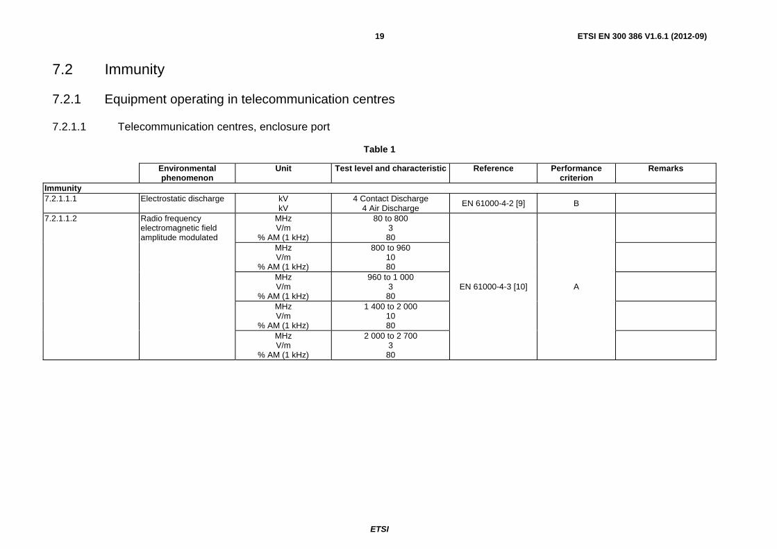
7.2.1.1 Telecommunication centres, enclosure port
Table 1
Environmental phenomenon
Unit Test level and characteristic Reference Performance criterion
Remarks
Immunity 7.2.1.1.1 Electrostatic discharge kV
kV 4 Contact Discharge
4 Air Discharge EN 61000-4-2 [9] B
7.2.1.1.2 Radio frequency electromagnetic field amplitude modulated
MHz V/m
% AM (1 kHz)
80 to 800 3
80
EN 61000-4-3 [10] A
MHz V/m
% AM (1 kHz)
800 to 960 10 80
MHz V/m
% AM (1 kHz)
960 to 1 000 3
80
MHz V/m
% AM (1 kHz)
1 400 to 2 000 10 80
MHz V/m
% AM (1 kHz)
2 000 to 2 700 3
80
ETSI
ETSI EN 300 386 V1.6.1 (2012-09) 20
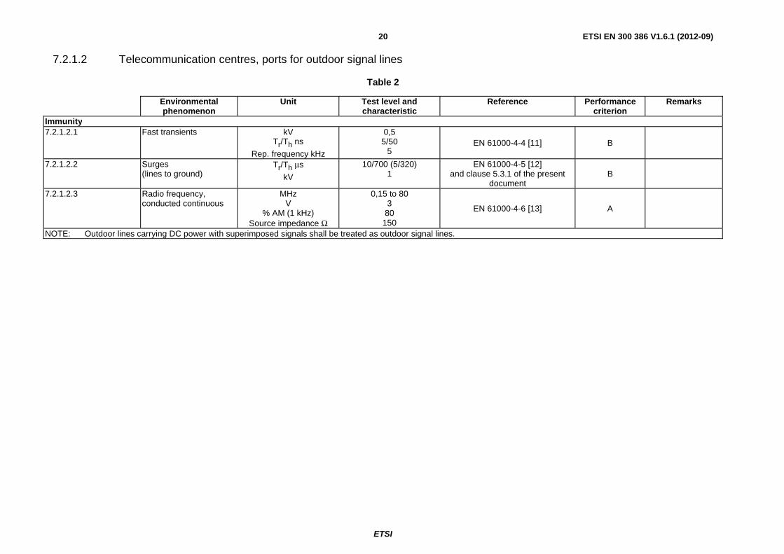
7.2.1.2 Telecommunication centres, ports for outdoor signal lines
Table 2
Environmental phenomenon
Unit Test level and characteristic
Reference Performance criterion
Remarks
Immunity 7.2.1.2.1 Fast transients kV
Tr/Th ns
Rep. frequency kHz
0,5 5/50
5 EN 61000-4-4 [11] B
7.2.1.2.2 Surges (lines to ground)
Tr/Th μs
kV
10/700 (5/320) 1
EN 61000-4-5 [12] and clause 5.3.1 of the present
document B
7.2.1.2.3 Radio frequency, conducted continuous
MHz V
% AM (1 kHz) Source impedance Ω
0,15 to 80 3
80 150
EN 61000-4-6 [13] A
NOTE: Outdoor lines carrying DC power with superimposed signals shall be treated as outdoor signal lines.
ETSI
ETSI EN 300 386 V1.6.1 (2012-09) 21
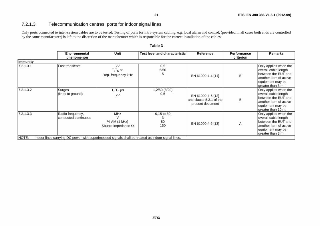
7.2.1.3 Telecommunication centres, ports for indoor signal lines
Only ports connected to inter-system cables are to be tested. Testing of ports for intra-system cabling, e.g. local alarm and control, (provided in all cases both ends are controlled by the same manufacturer) is left to the discretion of the manufacturer which is responsible for the correct installation of the cables.
Table 3
Environmental phenomenon
Unit Test level and characteristic Reference Performance criterion
Remarks
Immunity 7.2.1.3.1 Fast transients kV
TrTh ns
Rep. frequency kHz
0,5 5/50
5 EN 61000-4-4 [11] B
Only applies when the overall cable length between the EUT and another item of active equipment may be greater than 3 m.
7.2.1.3.2 Surges (lines to ground)
Tr/Th μs
kV
1,2/50 (8/20) 0,5
EN 61000-4-5 [12] and clause 5.3.1 of the
present document B
Only applies when the overall cable length between the EUT and another item of active equipment may be greater than 10 m.
7.2.1.3.3 Radio frequency, conducted continuous
MHz V
% AM (1 kHz) Source impedance Ω
0,15 to 80 3
80 150
EN 61000-4-6 [13] A
Only applies when the overall cable length between the EUT and another item of active equipment may be greater than 3 m.
NOTE: Indoor lines carrying DC power with superimposed signals shall be treated as indoor signal lines.
ETSI
ETSI EN 300 386 V1.6.1 (2012-09) 22
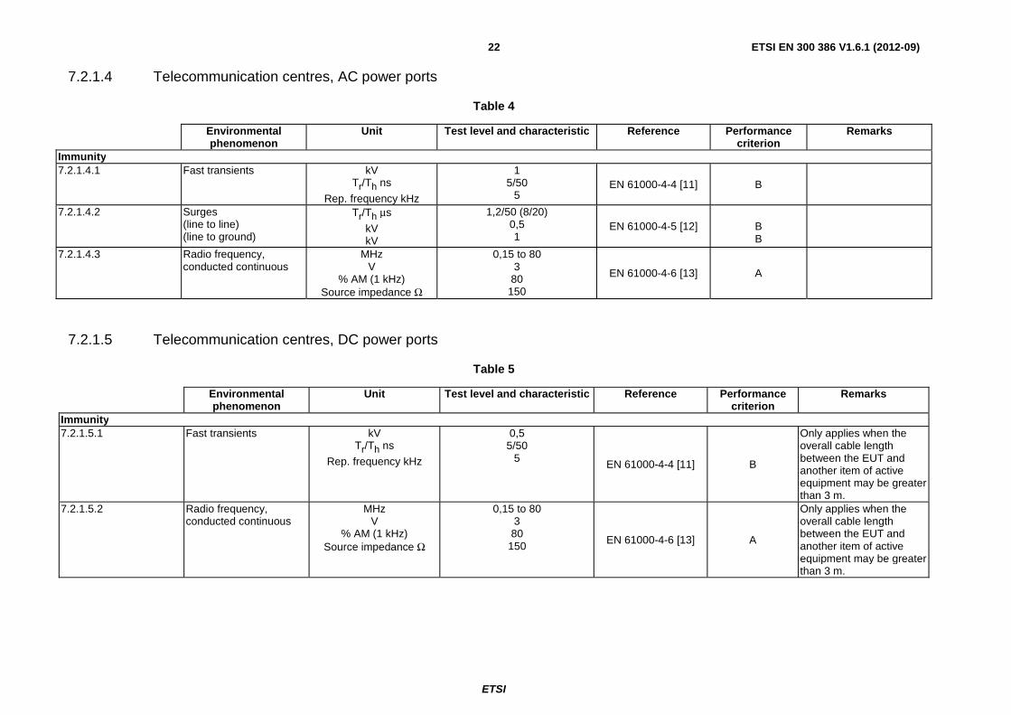
7.2.1.4 Telecommunication centres, AC power ports
Table 4
Environmental phenomenon
Unit Test level and characteristic Reference Performance criterion
Remarks
Immunity 7.2.1.4.1 Fast transients kV
Tr/Th ns
Rep. frequency kHz
1 5/50
5 EN 61000-4-4 [11] B
7.2.1.4.2 Surges (line to line) (line to ground)
Tr/Th μs
kV kV
1,2/50 (8/20) 0,5 1
EN 61000-4-5 [12]
B B
7.2.1.4.3 Radio frequency, conducted continuous
MHz V
% AM (1 kHz) Source impedance Ω
0,15 to 80 3
80 150
EN 61000-4-6 [13] A
7.2.1.5 Telecommunication centres, DC power ports
Table 5
Environmental phenomenon
Unit Test level and characteristic Reference Performance criterion
Remarks
Immunity 7.2.1.5.1 Fast transients kV
Tr/Th ns
Rep. frequency kHz
0,5 5/50
5 EN 61000-4-4 [11] B
Only applies when the overall cable length between the EUT and another item of active equipment may be greater than 3 m.
7.2.1.5.2 Radio frequency, conducted continuous
MHz V
% AM (1 kHz) Source impedance Ω
0,15 to 80 3 80
150 EN 61000-4-6 [13] A
Only applies when the overall cable length between the EUT and another item of active equipment may be greater than 3 m.
ETSI
ETSI EN 300 386 V1.6.1 (2012-09) 23
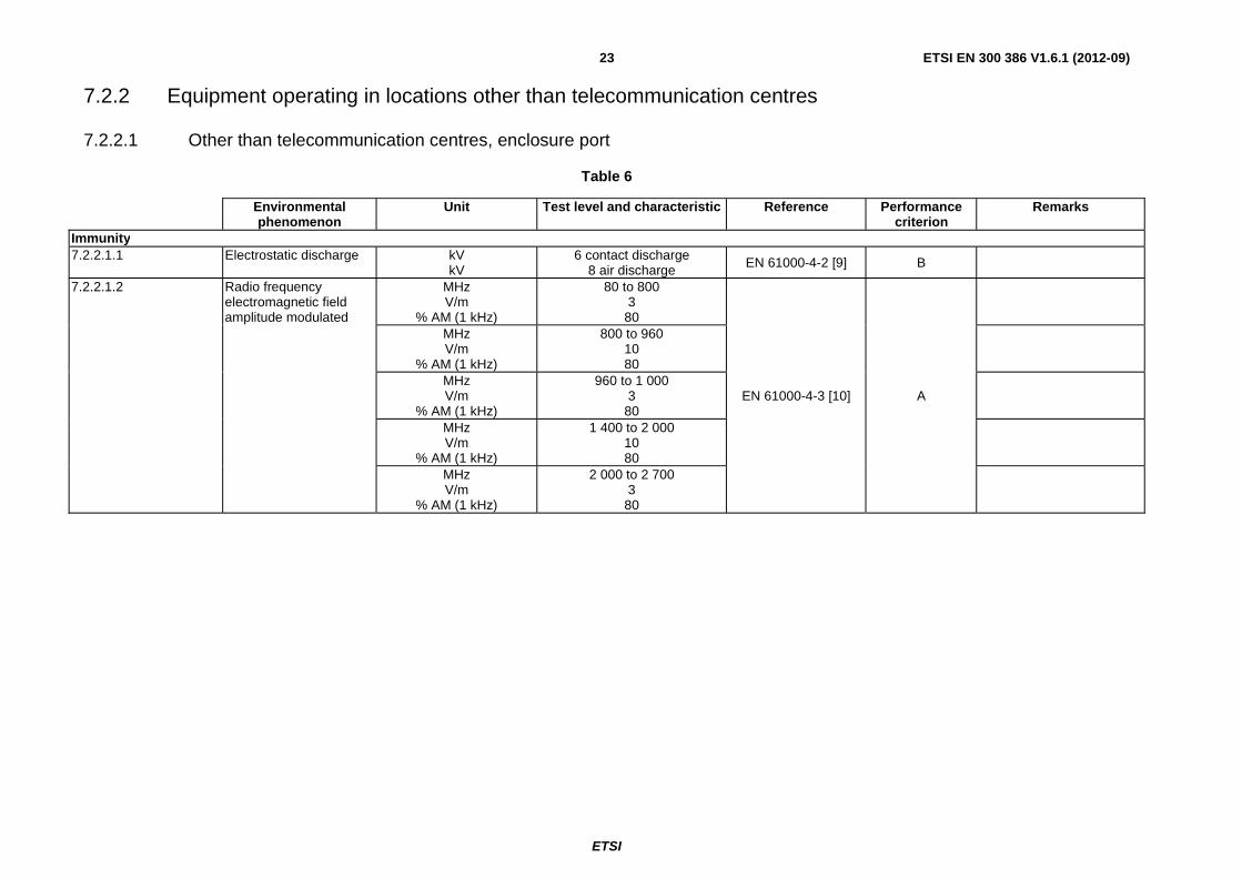
7.2.2 Equipment operating in locations other than telecommunication centres
7.2.2.1 Other than telecommunication centres, enclosure port
Table 6
Environmental phenomenon
Unit Test level and characteristic Reference Performance criterion
Remarks
Immunity 7.2.2.1.1 Electrostatic discharge kV
kV 6 contact discharge
8 air discharge EN 61000-4-2 [9] B
7.2.2.1.2 Radio frequency electromagnetic field amplitude modulated
MHz V/m
% AM (1 kHz)
80 to 800 3
80
EN 61000-4-3 [10] A
MHz V/m
% AM (1 kHz)
800 to 960 10 80
MHz V/m
% AM (1 kHz)
960 to 1 000 3
80
MHz V/m
% AM (1 kHz)
1 400 to 2 000 10 80
MHz V/m
% AM (1 kHz)
2 000 to 2 700 3
80
ETSI
ETSI EN 300 386 V1.6.1 (2012-09) 24
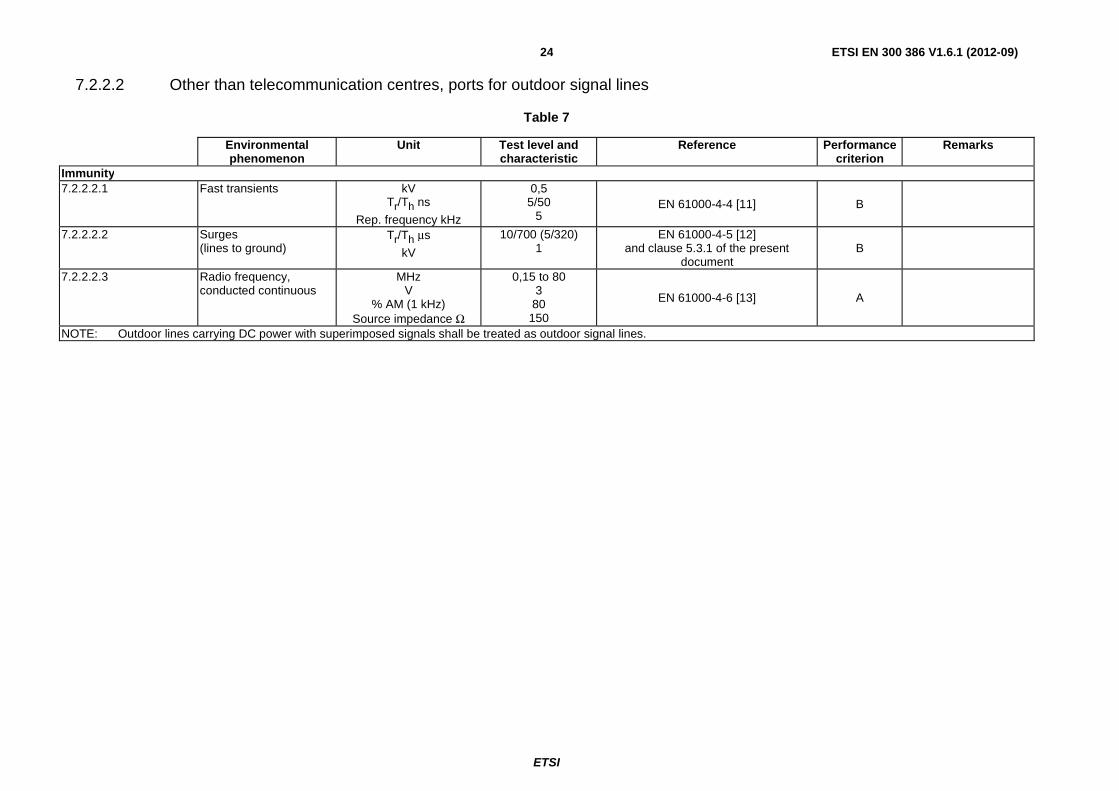
7.2.2.2 Other than telecommunication centres, ports for outdoor signal lines
Table 7
Environmental phenomenon
Unit Test level and characteristic
Reference Performance criterion
Remarks
Immunity 7.2.2.2.1 Fast transients kV
Tr/Th ns
Rep. frequency kHz
0,5 5/50
5 EN 61000-4-4 [11] B
7.2.2.2.2 Surges (lines to ground)
Tr/Th μs
kV
10/700 (5/320) 1
EN 61000-4-5 [12] and clause 5.3.1 of the present
document B
7.2.2.2.3 Radio frequency, conducted continuous
MHz V
% AM (1 kHz) Source impedance Ω
0,15 to 80 3
80 150
EN 61000-4-6 [13] A
NOTE: Outdoor lines carrying DC power with superimposed signals shall be treated as outdoor signal lines.
ETSI
ETSI EN 300 386 V1.6.1 (2012-09) 25
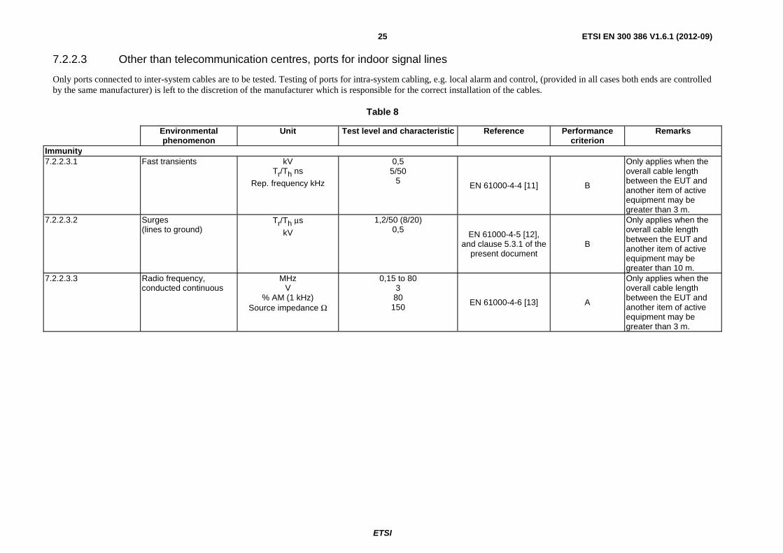
7.2.2.3 Other than telecommunication centres, ports for indoor signal lines
Only ports connected to inter-system cables are to be tested. Testing of ports for intra-system cabling, e.g. local alarm and control, (provided in all cases both ends are controlled by the same manufacturer) is left to the discretion of the manufacturer which is responsible for the correct installation of the cables.
Table 8
Environmental phenomenon
Unit Test level and characteristic Reference Performance criterion
Remarks
Immunity 7.2.2.3.1 Fast transients kV
Tr/Th ns
Rep. frequency kHz
0,5 5/50
5 EN 61000-4-4 [11] B
Only applies when the overall cable length between the EUT and another item of active equipment may be greater than 3 m.
7.2.2.3.2 Surges (lines to ground)
Tr/Th μs
kV
1,2/50 (8/20) 0,5
EN 61000-4-5 [12], and clause 5.3.1 of the
present document B
Only applies when the overall cable length between the EUT and another item of active equipment may be greater than 10 m.
7.2.2.3.3 Radio frequency, conducted continuous
MHz V
% AM (1 kHz) Source impedance Ω
0,15 to 80 3 80
150 EN 61000-4-6 [13] A
Only applies when the overall cable length between the EUT and another item of active equipment may be greater than 3 m.
ETSI
ETSI EN 300 386 V1.6.1 (2012-09) 26
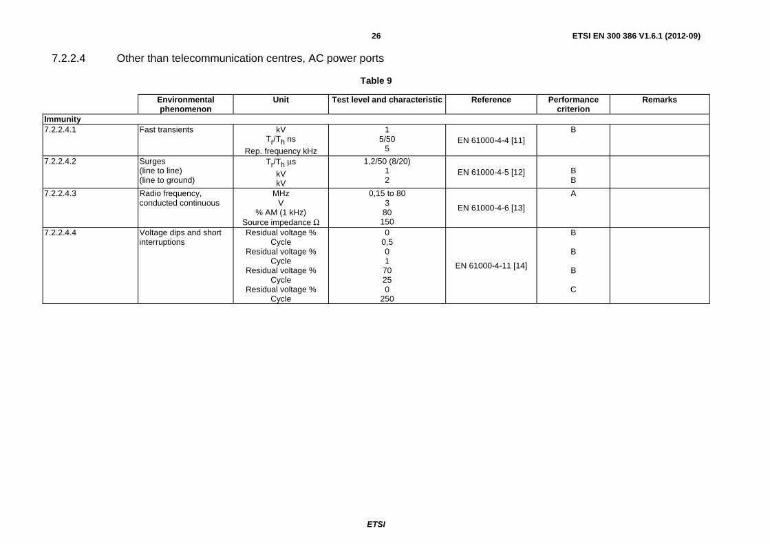
7.2.2.4 Other than telecommunication centres, AC power ports
Table 9
Environmental phenomenon
Unit Test level and characteristic Reference Performance criterion
Remarks
Immunity 7.2.2.4.1 Fast transients kV
Tr/Th ns
Rep. frequency kHz
1 5/50
5 EN 61000-4-4 [11]
B
7.2.2.4.2 Surges (line to line) (line to ground)
Tr/Th μs
kV kV
1,2/50 (8/20) 1 2
EN 61000-4-5 [12]
B B
7.2.2.4.3 Radio frequency, conducted continuous
MHz V
% AM (1 kHz) Source impedance Ω
0,15 to 80 3
80 150
EN 61000-4-6 [13]
A
7.2.2.4.4 Voltage dips and short interruptions
Residual voltage % Cycle
Residual voltage % Cycle
Residual voltage % Cycle
Residual voltage % Cycle
0 0,5 0 1
70 25 0
250
EN 61000-4-11 [14]
B
B
B
C
ETSI
ETSI EN 300 386 V1.6.1 (2012-09) 27
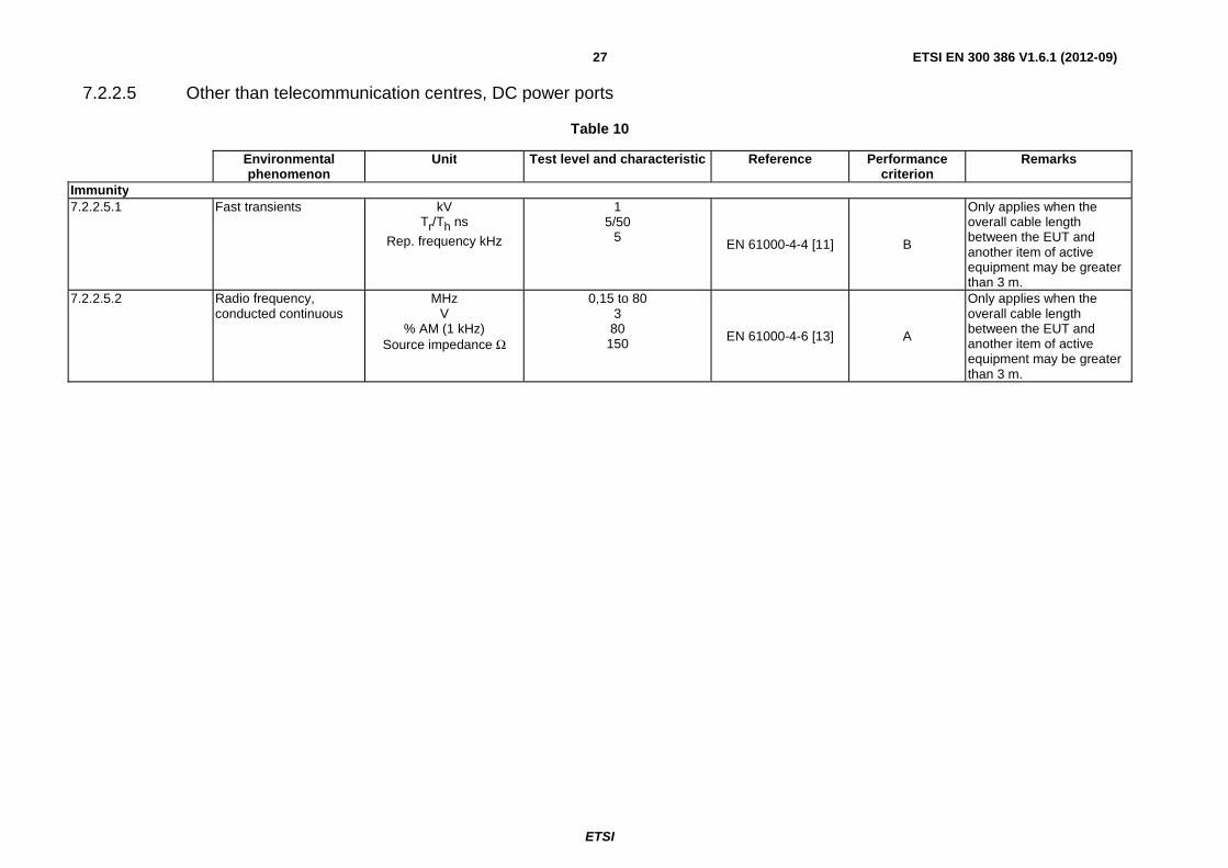
7.2.2.5 Other than telecommunication centres, DC power ports
Table 10
Environmental phenomenon
Unit Test level and characteristic Reference Performance criterion
Remarks
Immunity 7.2.2.5.1 Fast transients kV
Tr/Th ns
Rep. frequency kHz
1 5/50
5 EN 61000-4-4 [11] B
Only applies when the overall cable length between the EUT and another item of active equipment may be greater than 3 m.
7.2.2.5.2 Radio frequency, conducted continuous
MHz V
% AM (1 kHz) Source impedance Ω
0,15 to 80 3
80 150 EN 61000-4-6 [13] A
Only applies when the overall cable length between the EUT and another item of active equipment may be greater than 3 m.
ETSI
ETSI EN 300 386 V1.6.1 (2012-09) 28
8 General test configuration The EUT shall be configured and operated in accordance with the basic EMC standards.
The signal or control ports shall be correctly terminated either by auxiliary equipment necessary to exercise the ports or by their nominal impedance.
Adequate measures shall be taken to avoid any effects of unwanted signals on the measuring equipment used to monitor the performance of the EUT.
The equipment test conditions shall be as close as possible to the installed conditions, as defined by the manufacturer. Wiring shall be consistent with the manufacturer's recommended procedures, and the equipment shall be in its housing with all covers and access panels in place as in normal operation, unless otherwise stated. If the equipment is designed to be mounted in a rack or cabinet, it should be tested in this configuration.
Signal ports are divided into two categories:
• main signal ports which provide the telecommunications service (third party traffic);
• auxiliary signal ports, i.e. ports for alarms, maintenance, etc., which are only used by the operator or the service provider.
A sufficient number of ports shall be correctly terminated to ensure that the test is representative of normal operating conditions and the selection of ports shall be specified in the test report.
The earth connections of the EUT shall be connected to a reference earth according to the manufacturer's specifications.
Only cables that are permanently connected shall be included.
The types of the cables connected to the EUT shall be indicated in the test report.
The test configurations shall be recorded in the test report.
9 General operational conditions during testing The general operational conditions shall allow for appropriate measuring of the emission and for testing of immunity. Special exercising equipment and/or software may be used with the object of reducing the test time and to simulate traffic conditions.
The tests described shall be performed with the Equipment Under Test (EUT) powered up (i.e. connected to an appropriate power supply), and operating in a manner which is as representative of normal operation as possible.
Details on the evaluation of test results are given in annex B.
9.1 Equipment configuration Power and signal distribution, grounding, interconnecting cabling and physical placement of equipment of a test system shall simulate the typical application and usage in so far as is practicable, and shall be in accordance with the relevant product specifications of the manufacturer.
The configuration that tends to maximize the EUT's emission or minimize its immunity is not usually intuitively obvious and in most instances selection will involve some trial and error testing.
Where equipment may be connected with cables routed either overhead or from beneath (i.e. equipment mounted on a raised floor) the equipment shall be tested in a manner representative of an installation using overhead cable routing.
EXAMPLE: Interface cables may be moved or equipment re-orientated during initial stages of testing and the effects on the results observed.
ETSI
ETSI EN 300 386 V1.6.1 (2012-09) 29
Only configurations within the range of positions likely to occur in normal use need to be considered.
The configuration selected shall be fully detailed and documented in the test report, together with the justification for selecting that particular configuration.
9.2 Operation of multimedia network equipment Multimedia network equipment which is subjected simultaneously to different clauses of the present document and/or other standards shall be tested with each function operating in isolation, if this can be achieved without modifying the equipment internally. The equipment thus tested shall be deemed to have complied with the requirements of all clauses/standards when each function has satisfied the requirements of the relevant clause/standard.
For equipment for which it is not practical to test with each function operating in isolation, or where the isolation of a particular function would result in the equipment being unable to fulfil its primary function, the equipment shall be deemed to have complied if the relevant provisions of each clause/standard are taken into account, with the necessary functions operative.
In case of emission requirements, if the limits for the different functions are not identical, the highest limits for the functions in operation apply, taking into account the specific measurement conditions related to those (highest) limits.
EXAMPLE 1: For telecommunication equipment provided with an RF port for CATV distribution, this would mean that the emission requirements at the RF port shall be according to EN 50083-2 [3].
In case of immunity requirements, if the test levels for the different functions are not identical, the level for the function under test applies, taking into account the performance criteria for this function.
EXAMPLE 2: For telecommunication equipment provided with an RF port for CATV distribution, this would mean that the RF port shall be measured according to EN 50083-2 [3].
Field immunity of telecommunication functions shall be measured according to the present document. Field immunity of the distribution of television and sound signal functions shall be measured according to EN 50083-2 [3].
10 General immunity conditions If the minimum performance level or permissible performance loss is not specified in the following clauses or by the manufacturer, then either of these may be deduced from the product description and documentation, and what the user may reasonably expect from the apparatus if used as intended.
10.1 General performance criteria The general performance criteria apply for those ports for which no specific performance criteria are defined (e.g. auxiliary ports) in the present document.
Where the specific immunity criteria are not relevant or in appropriate, relevant justification shall be included in the test report highlighting how the EUT was fully exercised and met the general immunity criteria defined in this clause.
Performance criterion A:
The apparatus shall continue to operate as intended. No degradation of performance or loss of function is allowed below a performance level specified by the manufacturer when the apparatus is used as intended. In some cases the performance level may be replaced by a permissible loss of performance. If the minimum performance level or the permissible performance loss is not specified by the manufacturer, then either of these may be deduced from the product description and documentation and what the user may reasonably expect from the apparatus if used as intended.
ETSI
ETSI EN 300 386 V1.6.1 (2012-09) 30
Performance criterion B:
The apparatus shall continue to operate as intended after the test. No degradation of performance or loss of function is allowed below a performance level specified by the manufacturer, when the apparatus is used as intended. In some cases the performance level may be replaced by a permissible loss of performance. During the exposure to an electromagnetic phenomenon, degradation of performance is, however, allowed. No change of actual operating state or stored data is allowed. If the minimum performance level or the permissible performance loss is not specified by the manufacturer, then either of these may be deduced from the product description and documentation and what the user may reasonably expect from the apparatus if used as intended.
Performance criterion C:
Temporary loss of function is allowed, provided the function is self-recoverable or can be restored by the operation of the controls, or, in the case of switching equipment, by normal subsequent use.
11 Switching equipment specific requirements
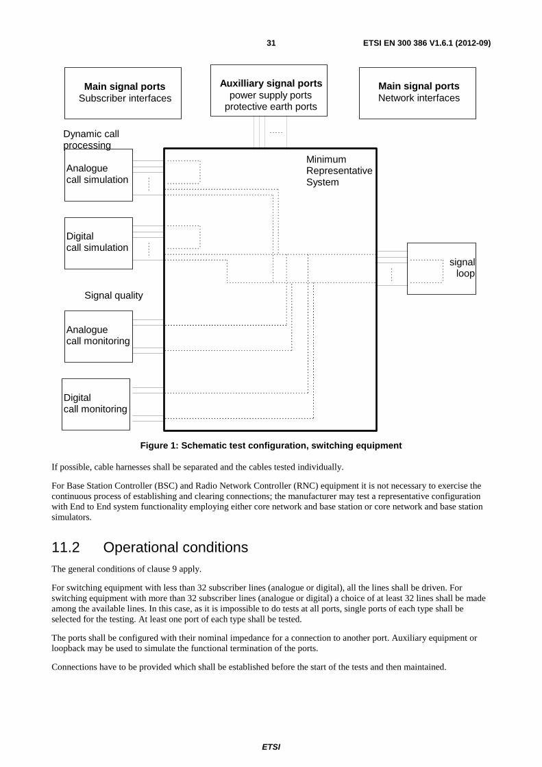
11.1 Test configuration For network switching equipment, two separate processes are monitored simultaneously, see figure 1. The first is the continuous process of establishing and clearing connections and the second is the stable situation of monitoring signal quality during testing. It is to be considered that at least a part of the set-up for both processes covers the full signal path from subscriber to the network. The signal loop at the network end can either be established by test equipment or by a simple cable loop. In the later case the simulation of normal grounding and connection practice is required.
The test equipment may be digital or analogue signal analyser as required. The test equipment may also loop back the test signal.
ETSI
ETSI EN 300 386 V1.6.1 (2012-09) 31
Main signal portsNetwork interfaces
Main signal portsSubscriber interfaces
Auxilliary signal portspower supply ports
protective earth ports
MinimumRepresentativeSystem
Analoguecall simulation
Digitalcall simulation
Digitalcall monitoring
Analoguecall monitoring
Signal quality
Dynamic callprocessing
signalloop
Figure 1: Schematic test configuration, switching equipment
If possible, cable harnesses shall be separated and the cables tested individually.
For Base Station Controller (BSC) and Radio Network Controller (RNC) equipment it is not necessary to exercise the continuous process of establishing and clearing connections; the manufacturer may test a representative configuration with End to End system functionality employing either core network and base station or core network and base station simulators.
11.2 Operational conditions The general conditions of clause 9 apply.
For switching equipment with less than 32 subscriber lines (analogue or digital), all the lines shall be driven. For switching equipment with more than 32 subscriber lines (analogue or digital) a choice of at least 32 lines shall be made among the available lines. In this case, as it is impossible to do tests at all ports, single ports of each type shall be selected for the testing. At least one port of each type shall be tested.
The ports shall be configured with their nominal impedance for a connection to another port. Auxiliary equipment or loopback may be used to simulate the functional termination of the ports.
Connections have to be provided which shall be established before the start of the tests and then maintained.
ETSI
ETSI EN 300 386 V1.6.1 (2012-09) 32
11.2.1 Emission
The general requirements for test methods are described in clause 6 of the present document.
11.2.2 Immunity
The general requirements for test methods are described in clause 5 of the present document.
Furthermore, for the immunity testing using continuous phenomena, the following selected frequencies shall be investigated in addition to the sweep:
• the clock frequencies inside the specified frequency band of the test;
• 434 MHz, 450 MHz, 850 MHz, 900 MHz, 1 800 MHz, 1 950 MHz, 2 100 MHz and 2 400 MHz (±1 %), (RF field);
• 13,56 MHz and 27,12 MHz (±1 %) (RF voltage).
11.3 Specific immunity performance criteria For the switching equipment the following main signal ports are recognized:
• analogue ports (e.g. analogue subscribers' lines, analogue interfaces to transmission equipment);
• digital ports (e.g. digital subscribers' lines (ISDN), digital connections to transmission equipment).
The interfaces shall operate as described in the following clauses.
11.3.1 Digital port performance criteria
11.3.1.1 Performance criterion A (continuous phenomena)
During the sweep:
• the established connections shall be maintained throughout testing and the transfer of information shall be within the limits of the manufacturer's specification;
• loss of frame alignment or loss of synchronization is not allowed during each individual exposure (if applicable).
For selected frequencies (see clause 11.2.2):
• it shall be possible to establish a connection between two ports;
• it shall be possible to clear a connection in a controlled manner.
11.3.1.2 Performance criterion B (transient phenomena)
The established connections shall be maintained throughout testing except in the case of surge immunity testing at 1 kV where disconnection is allowed on the port being tested:
• it shall be possible to establish a connection between two ports after the end of the transient disturbances;
• it shall be possible to clear a connection in a controlled manner after the end of the transient disturbances.
11.3.1.3 Performance criterion C (interruptions)
The general performance criterion C applies.
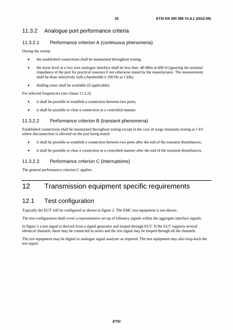
ETSI
ETSI EN 300 386 V1.6.1 (2012-09) 33
11.3.2 Analogue port performance criteria
11.3.2.1 Performance criterion A (continuous phenomena)
During the sweep:
• the established connections shall be maintained throughout testing;
• the noise level at a two wire analogue interface shall be less than -40 dBm at 600 Ω (ignoring the nominal impedance of the port for practical reasons) if not otherwise stated by the manufacturer. The measurement shall be done selectively with a bandwidth ≤ 100 Hz at 1 kHz;
• dialling tones shall be available (if applicable).
For selected frequencies (see clause 11.2.2):
• it shall be possible to establish a connection between two ports;
• it shall be possible to clear a connection in a controlled manner.
11.3.2.2 Performance criterion B (transient phenomena)
Established connections shall be maintained throughout testing except in the case of surge immunity testing at 1 kV where disconnection is allowed on the port being tested:
• it shall be possible to establish a connection between two ports after the end of the transient disturbances;
• it shall be possible to clear a connection in a controlled manner after the end of the transient disturbances.
11.3.2.3 Performance criterion C (interruptions)
The general performance criterion C applies.
12 Transmission equipment specific requirements
12.1 Test configuration Typically the EUT will be configured as shown in figure 2. The EMC test equipment is not shown.
The test configuration shall cover a representative set up of tributary signals within the aggregate interface signals.
In figure 2 a test signal is derived from a signal generator and looped through EUT. If the EUT supports several identical channels, these may be connected in series and the test signal may be looped through all the channels.
The test equipment may be digital or analogue signal analyser as required. The test equipment may also loop-back the test signal.
ETSI
ETSI EN 300 386 V1.6.1 (2012-09) 34
Mainsignalports
EUT
>>
<
<
Mainsignalports
TXTX
TXTX
RX
RXRX
RX
TESTEQUIPMENT
(e.g. Loop Back)
TESTEQUIPMENT
(sign. Analyser)
Figure 2: Schematic test configuration
12.2 Operational conditions The general conditions of clause 9 apply.
An appropriate test signal shall be used. The test signal shall be stated in the test report. The preferred test signal is the Pseudo Random Bit Sequence (PRBS) appropriate for the bit rate of the channel (ITU-T Recommendation O.150 [i.13]).
The modes of operation during testing shall be recorded in the test report.
12.2.1 Emission
The measurements shall be made in the operating mode, with the EUT producing the maximum emission, consistent with normal applications. The EUT load shall be adjusted within the range specified by manufacturer in order to maximize the emission.
Conducted emission shall be measured on the power input and output ports.
12.2.2 Immunity
Immunity tests shall be performed at nominal values of all signal conditions and with a typical value of line attenuation as declared by the manufacturer.
Conducted immunity testing shall be performed on power input and output ports and on signal ports.
For surge testing the conducted immunity tests shall be performed on auxiliary (signal) ports that are permanently connected in the normal installation.
12.3 Specific immunity performance criteria
12.3.1 Digital signal ports
The performance of the equipment shall be verified for digital signal ports:
• by measuring the number of induced bit errors on the main signal port during all exposures;
• by testing the functionality of the main signal port and the other signal ports after the exposure;
• by verifying that corruption of software and data held in memory has not occurred.
ETSI
ETSI EN 300 386 V1.6.1 (2012-09) 35
12.3.1.1 Performance criterion A (continuous phenomena)
The performance of the equipment shall be verified by measuring the additional errors induced due to the application of any electromagnetic phenomena. During the test sweep the established connection shall be maintained throughout the testing and the transfer of information shall be without any additional reproducible bit errors or loss of synchronization. If a degradation in performance is observed and the system is adaptive i.e. has the capability to automatically re-train in the presence of an interfering signal, then for Conducted Immunity tests only the following procedure shall be followed:
1) For each range of interfering frequencies where a degradation in performance is observed, three frequencies (beginning, middle and end) shall be identified.
2) At each of the frequencies identified in step 1, the interfering signal shall be turned on and the system allowed to re-train. If the system is able to re-train and then function without any additional reproducible bit errors or loss of synchronization then the system's performance is considered acceptable.
3) The frequencies identified in 1 and the data rates achieved in 2 shall be recorded in the test report.
12.3.1.2 Performance criterion B (transient phenomena)
Loss of frame alignment is not allowed during each individual exposure. No alarms shall be generated as a result of the electromagnetic stress.
The above does not apply to surge testing where some loss of frame alignment may be expected. For this test, the EUT shall operate as intended following the cessation of the exposure.
12.3.1.3 Performance criterion C (interruptions)
The general performance criterion C applies.
12.3.2 Analogue voice frequency signal ports
The performance of the equipment shall be verified for analogue voice frequency signal ports:
• by measuring the audio signal break-through (demodulated 1 kHz) on the signal port during continuous exposures in both signal path directions covering both analogue to digital conversion and digital to analogue conversion;
• by testing the functionality of the main signal port and the other signal ports after the transient exposures;
• by verifying that corruption of software and data held in memory has not occurred.
12.3.2.1 Performance criterion A (continuous phenomena)
The noise signal level received from the EUT measured in an impedance of 600 Ω shall not be greater than -40 dBm. The measurement shall be done selectively with a bandwidth ≤ 100 Hz at 1 kHz.
Connections shall be maintained throughout the test.
12.3.2.2 Performance criterion B (transient phenomena)
The established connections shall be maintained throughout testing except in the case of surge immunity testing at 1 kV where disconnection is allowed on the port being tested.
The EUT shall return automatically to normal performance after the cessation of the exposure.
12.3.3 SDH and PDH interfaces
12.3.3.1 Tributary and aggregate interfaces
The criteria specified in clause 12.3.1 apply to the interfaces specified in EN 300 166 [i.3] (electrical interface) and ETS 300 232 [i.4], ITU-T Recommendations G.783 [i.25] and G.798 [i.26] (optical interfaces).
ETSI
ETSI EN 300 386 V1.6.1 (2012-09) 36
12.3.4 ISDN interfaces
12.3.4.1 Primary rate access ISDN interfaces
The criteria specified in clause 12.3.1 apply to the interfaces specified in EN 300 011-1 [i.1].
12.3.4.2 Network termination NT1 for ISDN "U" interfaces
The criteria specified in clause 12.3.1 apply to the interfaces specified in ITU-T Recommendation G.961 [i.12].
12.3.4.3 Basic access ISDN interfaces
The criteria specified in clause 12.3.1 apply to the interfaces specified in EN 300 012-1 [i.2].
12.3.5 Analogue interfaces
12.3.5.1 Trunk interfaces and leased line interfaces
The criteria specified in clause 12.3.2 apply to the interfaces specified in ITU-T Recommendation G.712 [i.8].
12.3.5.2 Subscriber interfaces
The criteria specified in clause 12.3.2 apply to the interfaces specified in ITU-T Recommendation Q.552 [i.14].
12.3.6 V.10, V.11, V.24, V.28, V.36, X.24 and similar V.- and X.- series interfaces
The criteria specified in clause 12.3.1 apply to the interfaces specified in ITU-T Recommendations V.10 [i.15], V.11 [i.16], V.24 [i.17], V.28 [i.18], V.36 [i.19] and X.24 [i.20].
12.3.7 Ethernet and packet-data interfaces
To the interfaces specified in ISO/IEC 8802-3 [i.5] and ITU-T Recommendation X.25 [i.21], the criteria below apply.
12.3.7.1 Performance criterion A (continuous phenomena)
For interfaces which are intended for the transmission of third party data traffic, a selected port shall be connected to test equipment (e.g. a data communications analyser) as a single point-to-point data link. This will avoid excessive failed transmission attempts caused by data collisions and bus contention problems.
The interface shall be suitably exercised and monitored throughout the test period for errored frames.
No more than 5 % additional errored frames above the quiescent level shall be permitted during the exposure.
12.3.7.2 Performance criterion B (transient phenomena)
The established connections shall be maintained throughout testing except in the case of surge immunity testing at 1 kV where disconnection is allowed on the port being tested.
12.3.8 Service and maintenance interfaces
The functional performance of ports of this type not intended to be permanently connected and therefore not subjected to immunity testing shall be verified according to the manufacturer's specification following cessation of the electromagnetic exposure on other ports.
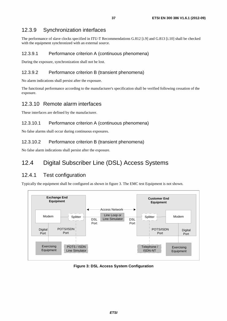
ETSI
ETSI EN 300 386 V1.6.1 (2012-09) 37
12.3.9 Synchronization interfaces
The performance of slave clocks specified in ITU-T Recommendations G.812 [i.9] and G.813 [i.10] shall be checked with the equipment synchronized with an external source.
12.3.9.1 Performance criterion A (continuous phenomena)
During the exposure, synchronization shall not be lost.
12.3.9.2 Performance criterion B (transient phenomena)
No alarm indications shall persist after the exposure.
The functional performance according to the manufacturer's specification shall be verified following cessation of the exposure.
12.3.10 Remote alarm interfaces
These interfaces are defined by the manufacturer.
12.3.10.1 Performance criterion A (continuous phenomena)
No false alarms shall occur during continuous exposures.
12.3.10.2 Performance criterion B (transient phenomena)
No false alarm indications shall persist after the exposure.
12.4 Digital Subscriber Line (DSL) Access Systems
12.4.1 Test configuration
Typically the equipment shall be configured as shown in figure 3. The EMC test Equipment is not shown.
Line Loop orLine SimulatorDSL
Port
Exchange EndEquipment
Customer EndEquipment
ExercisingEquipment
POTS / ISDNLine Simulator
Modem Modem
DigitalPort
ExercisingEquipment
DigitalPort
Access Network
DSLPort
Splitter
POTS/ISDNPort
Telephone /ISDN-NT
Splitter
POTS/ISDNPort
Figure 3: DSL Access System Configuration
ETSI
ETSI EN 300 386 V1.6.1 (2012-09) 38
For passband systems such ADSL and VDSL both ends of the equipment under test typically comprise a DSL modem and splitter/filter via which the POTS/ISDN port is presented. The modem and splitter may be separate units or combined into one unit.
For baseband systems such as HDSL and SDSL or passband systems where the DSL modem does not include the splitter then the equipment under test as shown in figure 3 will not include the parts denoted with a dotted line and hence measurements at the analogue port do not apply.
For the test setup, test loops shall be configured using a line simulator or real cable lengths.
12.4.2 Operational conditions
The general conditions of clause 9 shall apply.
The measurements shall be made with the digital transmission system trained up and operating at its nominal transmission rate such that the full frequency spectrum used by the system is utilized. If the system can be operated in asymmetric and symmetric modes then the testing shall be carried out for each of these modes of operation.
Immunity testing shall be performed at nominal values of all signal conditions and with a value of the line attenuation (i.e. using real cable or line simulator) such that the system will be operating at its minimum acceptable noise margin. (e.g. 6 dB noise margin relative to the system's nominal bit error ratio of 1E-7).
Further details on the noise margin can be found in the following documents:
ADSL ITU-T Recommendation G.996.1 [21] ITU-T Recommendation G.992.1 [25] ITU-T Recommendation G.992.3 [26] ITU-T Recommendation G.992.5 [27]
HDSL TS 101 135 [22] SDSL TS 101 524-1 [23] VDSL TS 101 270-1 [24]
Ports should be either terminated in their nominal impedance or connected to auxiliary equipment that simulates the functional termination of the port.
12.4.3 Immunity
The test methods are given in clause 5 of the present document. Conducted immunity testing shall be performed on all power input ports, DSL port and POTS/ISDN port. Testing on the digital port of the equipment need only be performed if the length of cable that can be attached to the port exceeds 3 m (10 m for surge tests).
12.4.4 Specific Immunity performance criteria
The performance of the equipment shall be verified by:
• Measuring the additional errors induced due to the application of any electromagnetic phenomena.
• Measuring the audio signal break-through (demodulated 1 kHz) at any POTS port whilst continuous interference phenomena are applied.
• Testing the functionality of the system at the cessation of test.
• Ensuring that any software or stored data corruption has not occurred.
• For ISDN ports the performance requirements of clause 12.3.4 shall apply.
ETSI
ETSI EN 300 386 V1.6.1 (2012-09) 39
12.4.4.1 Performance Criteria A (continuous phenomena)
• During the test sweep the established connection shall be maintained throughout the testing and the transfer of information shall be without any additional reproducible bit errors or loss of synchronization. If a degradation in performance is observed and the system is adaptive i.e. has the capability to automatically re-train in the presence of an interfering signal, then for Conducted Immunity tests only the following procedure shall be followed:
1) For each range of interfering frequencies where a degradation in performance is observed, three frequencies (beginning, middle and end) shall be identified.
2) At each of the frequencies identified in step 1, the interfering signal shall be turned on and the system is allowed to re-train. If the system is able to re-train and then function without any additional reproducible bit errors or loss of synchronization then the system's performance is considered acceptable.
3) The frequencies identified in 1 and the data rates achieved in 2 shall be recorded in the test report.
• During the test sweep the demodulated noise level at the POTS port shall be less than -40 dBm at 600 Ω (ignoring the nominal port impedance for practical reasons) if not otherwise stated by the manufacturer. The measurement shall be done selectively with a bandwidth ≤ 100 Hz at 1 kHz. As an alternative method the acoustic Sound Pressure Level (SPL) at the receiver of a telephone connected to the two-wire analogue interface shall not exceed 55 dB (SPL) when measured in a bandwidth ≤ 100 Hz at 1 kHz.
12.4.4.2 Performance Criteria B (transient phenomena)
The general performance criteria B shall apply in that errors are acceptable during the application of the test. However the application of the test shall not cause the system to lose the established connection or delay function (e.g. by re-train). At the cessation of the test the system shall continue to function in the state established prior to the application of the test, without user intervention.
The above performance criteria do not apply to surge testing. For this test, the EUT shall not lose the established connection and shall operate as intended following the cessation of the exposure.
12.4.4.3 Performance Criteria C (interruptions)
The general performance criteria C shall apply.
13 Power supply equipment specific conditions This clause is not applicable to power supplies i.e. DC-DC converters, AC-DC adapters and supplies incorporated within network equipment. It is intended for power supplies aimed at the generation of power for distribution within telecomm centres.
13.1 Test configuration Typically the EUT will be configured as shown in figures 4 and 5. The EMC test equipment is not shown.
The earth connections of the EUT shall be connected to a reference earth according to the manufacturer specifications.
The EUT load shall be resistive unless otherwise specified by the manufacturer.
For EUT with DC output and battery back-up, EMC tests shall be performed without the battery unless otherwise specified.
Uninterruptible power supplies shall also be tested whilst feeding from the battery only (AC mains off).
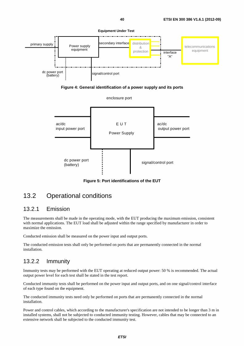
ETSI
ETSI EN 300 386 V1.6.1 (2012-09) 40
dc power port(battery)
Power supplyequipment
secondary interfaceprimary supply
signal/control port
Equipment Under Test
distribution&
protection interface"A"
telecommunicationsequipment
Figure 4: General identification of a power supply and its ports
enclosure port
signal/control port
E U T
Power Supplyinput power port output power port
dc power port(battery)
ac/dcac/dc
Figure 5: Port identifications of the EUT
13.2 Operational conditions
13.2.1 Emission
The measurements shall be made in the operating mode, with the EUT producing the maximum emission, consistent with normal applications. The EUT load shall be adjusted within the range specified by manufacturer in order to maximize the emission.
Conducted emission shall be measured on the power input and output ports.
The conducted emission tests shall only be performed on ports that are permanently connected in the normal installation.
13.2.2 Immunity
Immunity tests may be performed with the EUT operating at reduced output power: 50 % is recommended. The actual output power level for each test shall be stated in the test report.
Conducted immunity tests shall be performed on the power input and output ports, and on one signal/control interface of each type found on the equipment.
The conducted immunity tests need only be performed on ports that are permanently connected in the normal installation.
Power and control cables, which according to the manufacturer's specification are not intended to be longer than 3 m in installed systems, shall not be subjected to conducted immunity testing. However, cables that may be connected to an extensive network shall be subjected to the conducted immunity test.
ETSI
ETSI EN 300 386 V1.6.1 (2012-09) 41
13.3 Specific immunity performance criteria The ports of the power supply equipment (figure 6) that shall be monitored during the tests can be categorized as one of:
• DC secondary interface;
• AC secondary interface; or
• control/signal interface.
The manufacturer shall, at the time of submission of the equipment for test, supply the following information to be recorded in the test report:
• the primary functions of the power supply equipment to be tested;
• the intended functions of the power supply equipment, which shall be in accordance with the documentation accompanying the equipment and sales literature as appropriate;
• the auxiliary equipment to be combined with the power supply equipment;
• a list of ports, classified as AC/DC power port or control/signal port;
• the operating conditions.
13.3.1 Alternating current secondary interface
13.3.1.1 Performance criterion A (continuous phenomena)
During the exposure, the AC secondary range shall be in accordance with the normal service condition defined in ETS 300 132-1 [15].
The long-term voltage fluctuations at the AC secondary interface shall be within ±10 % of the nominal voltage.
During and after the exposure, the EUT shall operate without alarms, false alarm indications (power supply failure, protection failure, etc.) and false display indications.
13.3.1.2 Performance criterion B (transient phenomena)
Voltage interruptions at the AC secondary interface shall last no longer than 20 ms. The time between two voltage interruptions shall be no less than 10 s.
The voltage fluctuations at the AC secondary interface shall be in accordance with the requirements of ETS 300 132-1 [15]:
• for < 500 ms with respect to rms value: no worse than ±15 % of nominal value;
• for < 2 ms with respect to actual value: no worse than ±40 % of nominal value.
The frequency at the AC secondary interface shall not vary by more than ±3 Hz and shall return to the nominal value within 5 s.
Peaks with a duration shorter than 0,25 of one period (5 ms for a 50 Hz system), which appear during the exposure, are permissible.
After the exposure, the EUT shall operate without alarms or false alarm indications (power supply failure, protection failure, etc.) or false display indications.
Self recovery to normal performance shall occur at the cessation of the exposure.
ETSI
ETSI EN 300 386 V1.6.1 (2012-09) 42
13.3.2 Direct current secondary interface
13.3.2.1 Performance criterion A (continuous phenomena)
During the exposure, the DC secondary voltage range shall be in accordance with the normal service conditions defined in EN 300 132-2 [16].
The maximum level of wide band noise at the DC secondary interface shall not exceed the limits specified in table 11 of the present document (this requirement is taken from the EN 300 132-2 [16]).
Table 11: Level of wide band noise
Frequency Voltages 25 Hz to 5 kHz 10 mV Upsorms (measured over a 50 Ω impedance)
The reference method of measurement is with a psophometer conforming to ITU-T Recommendation O.41 [20].
During and after the exposure, the EUT shall operate without alarms or false alarm indications (power supply failure, protection failure, etc.) and false display indications.
13.3.2.2 Performance criterion B (transient phenomena)
After the exposure, the EUT shall operate without alarms or false alarm indications (power supply failure, protection failure, etc.) and false display indications:
• the DC secondary voltage during the exposure shall not exceed the following value:
- for -48 V DC nominal value: -60 V;
- for -60 V DC nominal value: -75 V;
• short peaks, which appear during the application of the tests, shall be ignored.
13.3.3 Control/signal interface
The control and signal ports need not be monitoring during the tests, because they are not considered to be primary functions.
13.3.4 Tertiary supply interface
To be considered only for special cases. Performance criteria should be derived from the product specifications.
14 Supervisory equipment specific conditions
14.1 Test configuration Exercising equipment e.g. a traffic simulator used for testing of other functions and equipment e.g. switching equipment can also be used as exercising equipment for supervisory equipment. Figure 6 shows two examples for a possible test configuration. The EMC test equipment is not shown.
Parts of the supervisory equipment (e.g. terminals) may be connected together but installed at locations other than the supervised equipment. For the purpose of EMC testing, these parts may be tested simultaneously and at the same location as the supervised equipment.
Example A shows a configuration with an external traffic simulator. In example B a test load simulator software is used. The use of either or both configurations is possible. The EMC tests shall be carried out during normal operation of supervisory equipment.
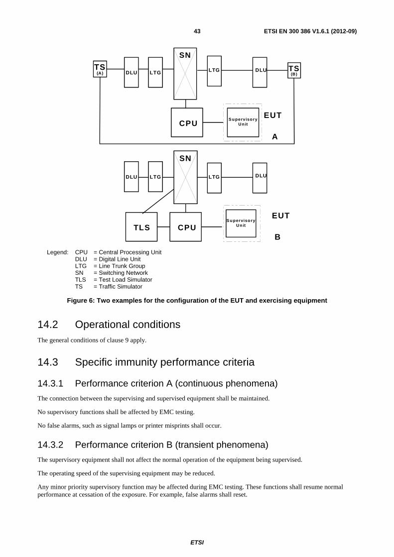
ETSI
ETSI EN 300 386 V1.6.1 (2012-09) 43
(B)TSTS
(A)
A
DLU LTG LTG DLU
CPUEUT
SN
S upervisoryUnit
DLU LTG LTG DLU
CPUTLSB
SN
S upervisoryUnit
EUT
Legend: CPU = Central Processing Unit DLU = Digital Line Unit LTG = Line Trunk Group SN = Switching Network TLS = Test Load Simulator TS = Traffic Simulator
Figure 6: Two examples for the configuration of the EUT and exercising equipment
14.2 Operational conditions The general conditions of clause 9 apply.
14.3 Specific immunity performance criteria
14.3.1 Performance criterion A (continuous phenomena)
The connection between the supervising and supervised equipment shall be maintained.
No supervisory functions shall be affected by EMC testing.
No false alarms, such as signal lamps or printer misprints shall occur.
14.3.2 Performance criterion B (transient phenomena)
The supervisory equipment shall not affect the normal operation of the equipment being supervised.
The operating speed of the supervising equipment may be reduced.
Any minor priority supervisory function may be affected during EMC testing. These functions shall resume normal performance at cessation of the exposure. For example, false alarms shall reset.
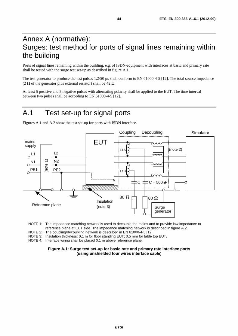
ETSI
ETSI EN 300 386 V1.6.1 (2012-09) 44
Annex A (normative): Surges: test method for ports of signal lines remaining within the building Ports of signal lines remaining within the building, e.g. of ISDN-equipment with interfaces at basic and primary rate shall be tested with the surge test set-up as described in figure A.1.
The test generator to produce the test pulses 1,2/50 μs shall conform to EN 61000-4-5 [12]. The total source impedance (2 Ω of the generator plus external resistor) shall be 42 Ω.
At least 5 positive and 5 negative pulses with alternating polarity shall be applied to the EUT. The time interval between two pulses shall be according to EN 61000-4-5 [12].
A.1 Test set-up for signal ports Figures A.1 and A.2 show the test set-up for ports with ISDN interface.
mainssupply
L1
N1
PE1
L2
N2
PE2(not
e 1)
Reference planeInsulation(note 3)
80 Ω 80 Ω
C C = 500nF
(note 2)
SimulatorCoupling Decoupling
EUT
Surgegenerator
L1A
L1B
NOTE 1: The impedance matching network is used to decouple the mains and to provide low impedance to reference plane at EUT side. The impedance matching network is described in figure A.2.
NOTE 2: The coupling/decoupling network is described in EN 61000-4-5 [12]. NOTE 3: Insulation thickness: 0,1 m for floor standing EUT; 0,5 mm for table top EUT. NOTE 4: Interface wiring shall be placed 0,1 m above reference plane.
Figure A.1: Surge test set-up for basic rate and primary rate interface ports (using unshielded four wires interface cable)
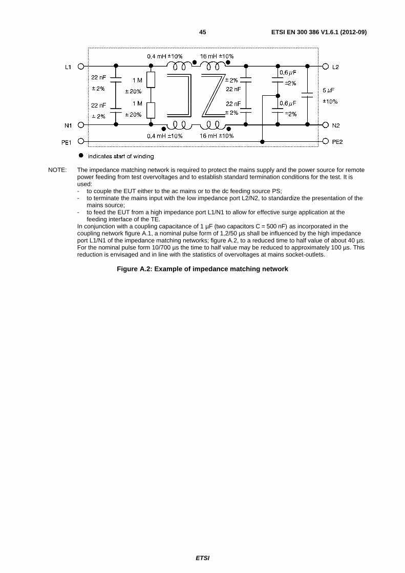
ETSI
ETSI EN 300 386 V1.6.1 (2012-09) 45
NOTE: The impedance matching network is required to protect the mains supply and the power source for remote power feeding from test overvoltages and to establish standard termination conditions for the test. It is used:
- to couple the EUT either to the ac mains or to the dc feeding source PS; - to terminate the mains input with the low impedance port L2/N2, to standardize the presentation of the
mains source; - to feed the EUT from a high impedance port L1/N1 to allow for effective surge application at the
feeding interface of the TE. In conjunction with a coupling capacitance of 1 µF (two capacitors C = 500 nF) as incorporated in the
coupling network figure A.1, a nominal pulse form of 1,2/50 µs shall be influenced by the high impedance port L1/N1 of the impedance matching networks; figure A.2, to a reduced time to half value of about 40 µs. For the nominal pulse form 10/700 µs the time to half value may be reduced to approximately 100 µs. This reduction is envisaged and in line with the statistics of overvoltages at mains socket-outlets.
Figure A.2: Example of impedance matching network
ETSI
ETSI EN 300 386 V1.6.1 (2012-09) 46
Annex B (informative): Evaluation of test results The test report will comprise:
a) a detailed description of the EUT, the physical aspects of the set-up and of the earthing conditions;
b) a list (and description) of the auxiliary equipment;
c) a detailed description of the operation modes and operational status of the EUT during emission testing;
d) the response of the EUT to the immunity test levels should be expressed in terms of the compliance criteria detailed in the present document;
e) a description of the test conditions (including temperature and relative humidity) and test results together with the method of test. If the method used differs from the preferred method, then the deviations should be recorded and justification made in the test report;
f) a statement of measurement uncertainty;
g) the calibration status of all test equipment used;
h) if an unrepeatable response occurs, this should be noted in the test report, but the response should not be taken into account in the assessment of the EUT.
Test reports
The work carried out by the testing laboratory will be covered by a report which accurately, clearly and unambiguously presents the test results and all other relevant information.
Each test report should include at least the following information:
a) name and address of testing laboratory and location where the test was carried out when different from the address of the testing laboratory;
b) unique identification of report (such as serial number) and of each page, and total number of pages of the report;
c) name and address of client;
d) description and identification of the test item;
e) date of receipt of test item and date(s) of performance of test;
f) identification of the test specification or description of the method or procedure;
g) description of sampling procedure, where relevant;
h) any deviations, additions to or exclusions from the test specification, and any other information relevant to a specific test;
i) identification of any non-standard test method or procedure utilized;
j) measurements, examinations and derived results, supported by tables, graphs, sketches and photographs as appropriate, and any failures identified;
k) a statement on measurement uncertainty (where relevant);
l) a signature and title or an equivalent marking of person(s) accepting technical responsibility for the test report and date of issue;
m) a statement to the effect that the test results relate only to the items tested;
ETSI
ETSI EN 300 386 V1.6.1 (2012-09) 47
n) a statement that the report cannot be reproduced except in full without the written approval of the testing laboratory.
Particular care and attention needs to be paid to the arrangement of the test report, especially with regard to presentation of the test data and ease of assimilation by the reader. The format should be carefully and specifically designed for each type of test carried out, but the headings should be standardized as far as possible.
Corrections or additions to a test report after issue can be made only by a further document suitably marked, e.g. "Amendment/Addendum to test report serial number... (or as otherwise identified)", and should meet the relevant requirements of the preceding clauses.
A test report should not include any advice or Recommendation arising from the test results.
Test results should be presented accurately, clearly, completely and unambiguously in accordance with instructions that may be part of the test methods.
Quantitative results should be given together with calculated or estimated uncertainty.
Test results obtained on items, which have been statistically selected from a larger lot, batch or production quantity, are frequently used to infer the properties of the lot, batch or production quantity. Any extrapolation of the test results to the properties of the lot, batch or production quantity should be contained in a separate document.
NOTE: Test results could be measured values, findings from the visual examination or practical use of the test item, derived results or any other type of observation from the testing activities. Test results may be supported by tables, photographs or graphical information of any kind appropriately identified.
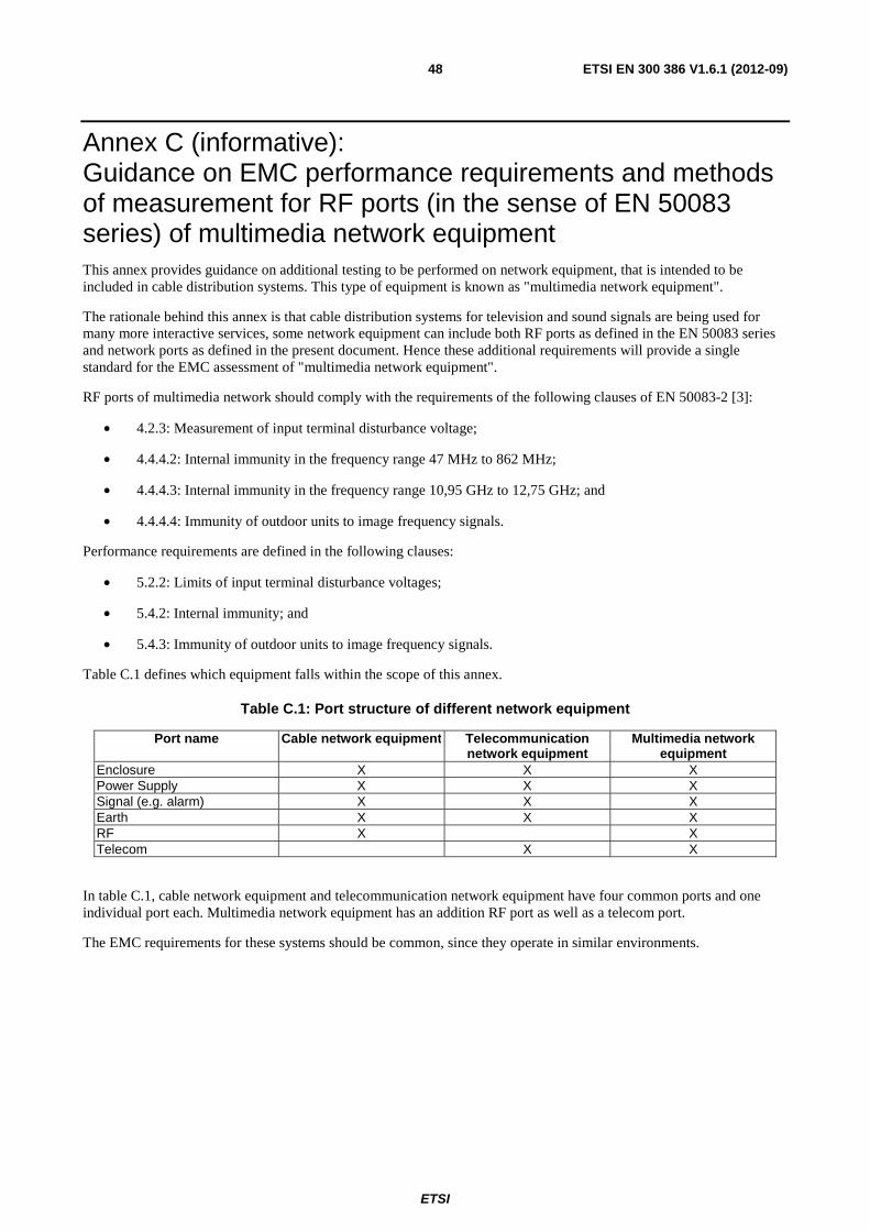
ETSI
ETSI EN 300 386 V1.6.1 (2012-09) 48
Annex C (informative): Guidance on EMC performance requirements and methods of measurement for RF ports (in the sense of EN 50083 series) of multimedia network equipment This annex provides guidance on additional testing to be performed on network equipment, that is intended to be included in cable distribution systems. This type of equipment is known as "multimedia network equipment".
The rationale behind this annex is that cable distribution systems for television and sound signals are being used for many more interactive services, some network equipment can include both RF ports as defined in the EN 50083 series and network ports as defined in the present document. Hence these additional requirements will provide a single standard for the EMC assessment of "multimedia network equipment".
RF ports of multimedia network should comply with the requirements of the following clauses of EN 50083-2 [3]:
• 4.2.3: Measurement of input terminal disturbance voltage;
• 4.4.4.2: Internal immunity in the frequency range 47 MHz to 862 MHz;
• 4.4.4.3: Internal immunity in the frequency range 10,95 GHz to 12,75 GHz; and
• 4.4.4.4: Immunity of outdoor units to image frequency signals.
Performance requirements are defined in the following clauses:
• 5.2.2: Limits of input terminal disturbance voltages;
• 5.4.2: Internal immunity; and
• 5.4.3: Immunity of outdoor units to image frequency signals.
Table C.1 defines which equipment falls within the scope of this annex.
Table C.1: Port structure of different network equipment
Port name Cable network equipment Telecommunication network equipment
Multimedia network equipment
Enclosure X X X Power Supply X X X Signal (e.g. alarm) X X X Earth X X X RF X X Telecom X X
In table C.1, cable network equipment and telecommunication network equipment have four common ports and one individual port each. Multimedia network equipment has an addition RF port as well as a telecom port.
The EMC requirements for these systems should be common, since they operate in similar environments.

ETSI
ETSI EN 300 386 V1.6.1 (2012-09) 49
Annex D (informative): Bibliography Council Directive 89/336/EEC of 3 May 1989 on the approximation of the laws of the Member States relating to electromagnetic compatibility.
CENELEC EN 61000-6-1 (2007): "Electromagnetic compatibility (EMC) -- Part 6-1: Generic standards - Immunity for residential, commercial and light-industrial environments".
ETSI
ETSI EN 300 386 V1.6.1 (2012-09) 50
History
Document history
Edition 1 December 1994 Publication as ETS 300 386-1
Corrigendum 1 April 1997 Corrigendum 1 to 1st Edition of ETS 300 386-1
V1.1.3 December 1997 Publication as EN 300 386-2 (Historical)
V1.2.1 March 2000 Publication
V1.3.1 September 2001 Publication
V1.3.2 May 2003 Publication
V1.3.3 April 2005 Publication
V1.4.1 April 2008 Publication
V1.5.1 October 2010 Publication
V1.6.1 April 2012 One-step Approval Procedure OAP 20120810: 2012-04-12 to 2012-08-10
V1.6.1 September 2012 Publication