Embed Size (px)
Citation preview
1
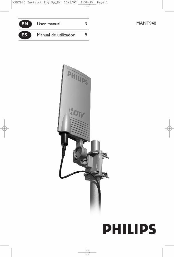
MANT940EN User manual 3
ES Manual de utilizador 9
MANT940 Instruct Eng Sp_SM 10/8/07 4:38 PM Page 1
EN
2
3 Safety Instructions4 Important Information5 Parts Included5 Mounting Instructions7 Connecting to Your TV8 Warranty8 Technical Support
Contents
STOPPhilips produces products of the highest quality. If you are havingtechnical problems, please call our accessory support help line at919-573-7854 before returning the product to the store. (please seepage 7 of this instruction manual for details “Before You Start”).
MANT940 Instruct Eng Sp_SM 10/8/07 4:38 PM Page 2
EN
3
Philips MANT940 Indoor/Outdoor UHF/VHF Television antenna
Antenna grounding and safety warning
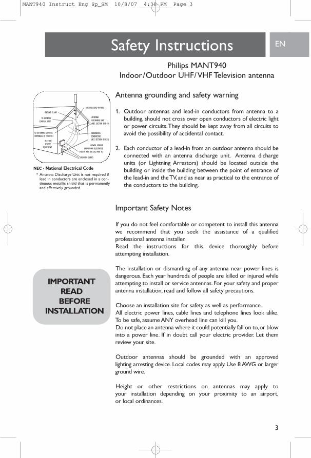
1. Outdoor antennas and lead-in conductors from antenna to abuilding, should not cross over open conductors of electric lightor power circuits.They should be kept away from all circuits toavoid the possibility of accidental contact.
2. Each conductor of a lead-in from an outdoor antenna should beconnected with an antenna discharge unit. Antenna dichargeunits (or Lightning Arrestors) should be located outside thebuilding or inside the building between the point of entrance ofthe lead-in and the TV, and as near as practical to the entrance ofthe conductors to the building.
Important Safety Notes
If you do not feel comfortable or competent to install this antennawe recommend that you seek the assistance of a qualified professional antenna installer.Read the instructions for this device thoroughly before attempting installation.
The installation or dismantling of any antenna near power lines isdangerous. Each year hundreds of people are killed or injured whileattempting to install or service antennas. For your safety and properantenna installation, read and follow all safety precautions.
Choose an installation site for safety as well as performance.All electric power lines, cable lines and telephone lines look alike.To be safe, assume ANY overhead line can kill you.Do not place an antenna where it could potentially fall on to,or blowinto a power line. If in doubt call your electric provider. Let themreview your site.
Outdoor antennas should be grounded with an approved lighting arresting device. Local codes may apply. Use 8 AWG or largerground wire.
Height or other restrictions on antennas may apply to your installation depending on your proximity to an airport,or local ordinances.
Safety Instructions
IMPORTANTREAD BEFORE
INSTALLATION
NEC - National Electrical Code* Antenna Discharge Unit is not required if
lead in conductors are enclosed in a con-tinuous metallic shield that is permanentlyand effectively grounded.
MANT940 Instruct Eng Sp_SM 10/8/07 4:38 PM Page 3
EN
4
Take the time to plan your installation procedure. Do all assemblywork on the antenna on the ground. Raise the completed antennaafter assembly.
Do NOT work on a wet, snowy or windy day or if a thunderstormis approaching. Do NOT use a metal ladder.
If the antenna assembly starts to fall, get away from it and let it fall.Remember that the antenna mast and cable are all excellent conduc-tors of electrical current.
Do NOT install the antenna by yourself. Be sure that there are twoother people available for help.
If any part of the antenna should come in contact with a power line. . . DON'T TOUCH IT OR TRY TO REMOVE IT YOURSELF. Callyour local power company immediately.They will remove it.
Should an electrical accident occur . . . DON'T TOUCH THE PERSON IN CONTACT WITH THE POWER LINE, or you too canbecome electrocuted. Instead, use a DRY board, stick, or rope topush or pull the victim away from the power lines and antenna.Onceclear, check the victim. If he has stopped breathing, immediatelyadminister cardiopulmonary resuscitation (CPR) and stay with him.Have someone else call for medical help.
Install wire antennas high enough that they will not be "walked into"by people.
Do not install antenna wire(s) over or under utility lines.
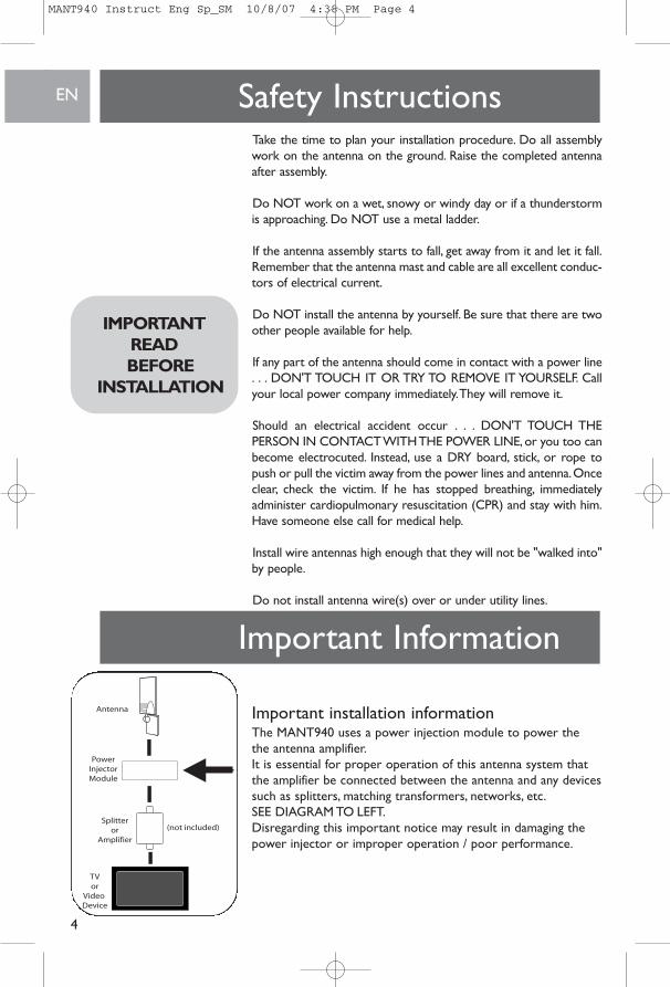
Important installation informationThe MANT940 uses a power injection module to power thethe antenna amplifier.It is essential for proper operation of this antenna system thatthe amplifier be connected between the antenna and any devicessuch as splitters, matching transformers, networks, etc.SEE DIAGRAM TO LEFT.Disregarding this important notice may result in damaging thepower injector or improper operation / poor performance.
Safety Instructions
IMPORTANTREAD BEFORE
INSTALLATION
Important Information
MANT940 Instruct Eng Sp_SM 10/8/07 4:38 PM Page 4
Parts included:
1. MANT940 Antenna . . . . . . . . . . . . . . . . . . . . 12. Power supply 120V to 6VDC . . . . . . . . . . . . 13. Wall / Mast Bracket . . . . . . . . . . . . . . . . . . . . 14. Nuts . . . . . . . . . . . . . . . . . . . . . . . . . . . . . . . . 25. U-Bolts . . . . . . . . . . . . . . . . . . . . . . . . . . . . . . 26. Mast clamps . . . . . . . . . . . . . . . . . . . . . . . . . . 27. Nuts with lock washers . . . . . . . . . . . . . . . . . 47. L-Bracket. . . . . . . . . . . . . . . . . . . . . . . . . . . . . 18. 2" Wood Screws . . . . . . . . . . . . . . . . . . . . . . . 49. 20' coax cable with connectors . . . . . . . . . . . 110. Weather Boot. . . . . . . . . . . . . . . . . . . . . . . . . 111. Power Injector . . . . . . . . . . . . . . . . . . . . . . . . 112. Plastic Anchors . . . . . . . . . . . . . . . . . . . . . . . . 4
Determining signal strengthBefore Installation determine the best location for optimum reception. It is important for the antenna to have an unobstructedpath to the transmitter.To determine the transmitter(s) location youcan consult the website http://www.antennaweb.org. For best resultsthe antenna should be facing the transmitter location.
For indoor wall mount installation:NOTE: Do all antenna assembly work on the ground beforeinstalling on a wall or an antenna mast.
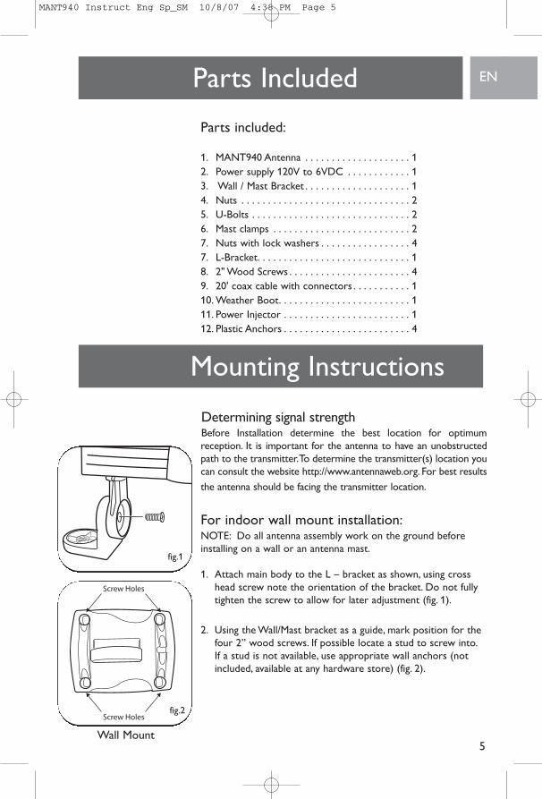
1. Attach main body to the L – bracket as shown, using crosshead screw note the orientation of the bracket. Do not fullytighten the screw to allow for later adjustment (fig. 1).
2. Using the Wall/Mast bracket as a guide, mark position for thefour 2” wood screws. If possible locate a stud to screw into.If a stud is not available, use appropriate wall anchors (notincluded, available at any hardware store) (fig. 2).
ENParts Included
5
Mounting Instructions
Wall Mount
fig.1
fig.2
MANT940 Instruct Eng Sp_SM 10/8/07 4:38 PM Page 5
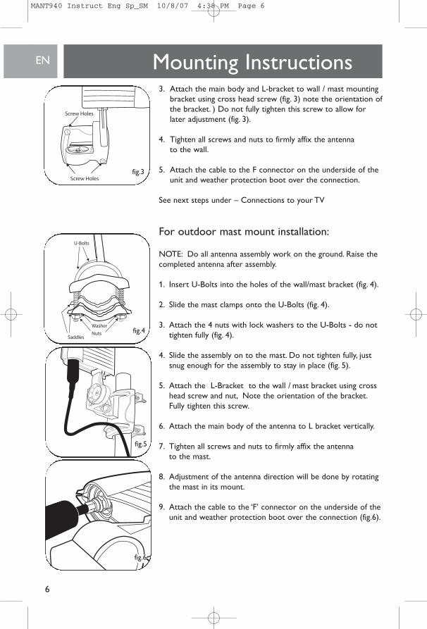
3. Attach the main body and L-bracket to wall / mast mountingbracket using cross head screw (fig. 3) note the orientation ofthe bracket. ) Do not fully tighten this screw to allow forlater adjustment (fig. 3).
4. Tighten all screws and nuts to firmly affix the antennato the wall.
5. Attach the cable to the F connector on the underside of theunit and weather protection boot over the connection.
See next steps under – Connections to your TV
For outdoor mast mount installation:
NOTE: Do all antenna assembly work on the ground. Raise thecompleted antenna after assembly.
1. Insert U-Bolts into the holes of the wall/mast bracket (fig. 4).
2. Slide the mast clamps onto the U-Bolts (fig. 4).
3. Attach the 4 nuts with lock washers to the U-Bolts - do nottighten fully (fig. 4).
4. Slide the assembly on to the mast. Do not tighten fully, justsnug enough for the assembly to stay in place (fig. 5).
5. Attach the L-Bracket to the wall / mast bracket using crosshead screw and nut, Note the orientation of the bracket.Fully tighten this screw.
6. Attach the main body of the antenna to L bracket vertically.
7. Tighten all screws and nuts to firmly affix the antenna to the mast.
8. Adjustment of the antenna direction will be done by rotatingthe mast in its mount.
9. Attach the cable to the ‘F’ connector on the underside of theunit and weather protection boot over the connection (fig.6).
EN Mounting Instructions
6
fig.3
fig.4
fig.5
fig.6
MANT940 Instruct Eng Sp_SM 10/8/07 4:38 PM Page 6
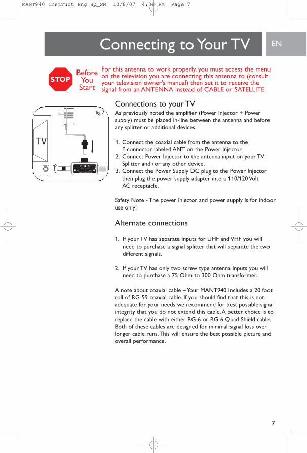
Connections to your TVAs previously noted the amplifier (Power Injector + Power supply) must be placed in-line between the antenna and beforeany splitter or additional devices.
1. Connect the coaxial cable from the antenna to the F connector labeled ANT on the Power Injector.
2. Connect Power Injector to the antenna input on your TV,Splitter and / or any other device.
3. Connect the Power Supply DC plug to the Power Injectorthen plug the power supply adapter into a 110/120 Volt AC receptacle.
Safety Note - The power injector and power supply is for indooruse only!
Alternate connections
1. If your TV has separate inputs for UHF and VHF you willneed to purchase a signal splitter that will separate the twodifferent signals.
2. If your TV has only two screw type antenna inputs you willneed to purchase a 75 Ohm to 300 Ohm transformer.
A note about coaxial cable – Your MANT940 includes a 20 footroll of RG-59 coaxial cable. If you should find that this is notadequate for your needs we recommend for best possible signalintegrity that you do not extend this cable.A better choice is toreplace the cable with either RG-6 or RG-6 Quad Shield cable.Both of these cables are designed for minimal signal loss overlonger cable runs.This will ensure the best possible picture andoverall performance.
ENConnecting to Your TV
7
fig.7
For this antenna to work properly, you must access the menuon the television you are connecting this antenna to (consultyour television owner’s manual) then set it to receive the signal from an ANTENNA instead of CABLE or SATELLITE.
STOPBefore
You Start
MANT940 Instruct Eng Sp_SM 10/8/07 4:38 PM Page 7
Limited Lifetime WarrantyPhilips warrants that this product shall be free from defects in mate-rial, workmanship and assembly, under normal use, in accordancewith the specifications and warnings, for as long as you own thisproduct.This warranty extends only to the original purchaser of theproduct, and is not transferable. To exercise your rights under thiswarranty, you must provide proof of purchase in the form of an orig-inal sales receipt that shows the product name and the date of pur-chase. For customer support or to obtain warranty service, pleasecall 919-573-7854.THERE ARE NO OTHER EXPRESS OR IMPLIEDWARRANTIES. Philips’ liability is limited to repair or, at its soleoption, replacement of the product. Incidental, special and conse-quential damages are disclaimed where permitted by law.This war-ranty gives you specific legal rights.You may also have other rightsthat vary from state to state.
Technical SupportFor Technical support send an email with the model number of theproduct and a detailed description of your problem to:
Email: [email protected]
©2007Accessories Service CenterPhilips Accessories and Computer Peripherals,Ledgewood, NJ 07852 USA
Quality assured in USA
Printed in China
EN Warranty
8
Technical Support
MANT940 Instruct Eng Sp_SM 10/8/07 4:38 PM Page 8
ES
9
10 Instrucciones de seguridadr11 Información importante12 Partes incluidas:13 Armado y montaje de la antena 114 Conexión de su TV15 Garantía limitada por vida15 Asistencia Técnica:
Contenido
PARADA
Philips fabrica productos de la mejor calidad. Si tiene algún problematécnico, llame a nuestra línea de ayuda de asistencia para accesoriosal 919-573-7854 antes de devolver el producto al establecimiento.(Consulte la página 14 de este manual de instrucciones para obtenerinformación "Antes de comenzar").
MANT940 Instruct Eng Sp_SM 10/8/07 4:38 PM Page 9
ES
10
Antena de televisión Philips MANT940 Interior / Exterior UHF / VHF
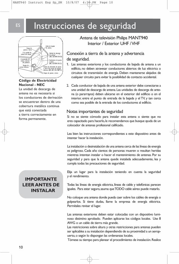
Conexión a tierra de la antena y advertencia de seguridad.1. Las antenas exteriores y los conductores de bajada de antena a un
edificio, no deben atravesar conductores abiertos de luz eléctrica ocircuitos de transmisión de energía. Deben mantenerse alejados decualquier circuito para evitar la posibilidad de contacto accidental.
2. Cada conductor de bajada de una antena exterior debe conectarse auna unidad de descarga de antena.Las unidades de descarga de ante-na (o pararrayos) deben ubicarse en el exterior del edificio o en elinterior, entre el punto de entrada de la bajada y el TV, y tan cercacomo sea posible de la entrada de los conductores al edificio.
Notas importantes de seguridad Si no se siente cómodo para instalar esta antena o siente que no eres capacitado para hacerlo, le recomendamos que busque ayuda de uncolocador de antenas profesional calificado.
Lea bien las instrucciones correspondientes a este dispositivo antes deintentar hacer la instalación.
La instalación o desinstalación de una antena cerca de las líneas de energíaes peligroso. Cada año cientos de personas mueren o resultan heridasmientras intentan instalar o hacer el mantenimiento de antenas. Por suseguridad y para que la antena quede instalada adecuadamente, lea ycumpla todas las precauciones de seguridad.
Elija un lugar para la instalación teniendo en cuenta la seguridad y el rendimiento.
Todas las líneas de energía eléctrica, líneas de cable y telefónicas pareceniguales. Para estar seguro,asuma que TODO cable aéreo puede matarlo.
No coloque una antena donde pueda caer sobre los cables de energía ogolpearlos. Si tiene dudas, llame la empresa de energía eléctrica.Permítales revisar el lugar.
Las antenas exteriores deben estar colocadas con un dispositivo lumi-noso distintivo aprobado. Pueden aplicarse los códigos locales. Use 8AWG o un cable de tierra más grande.Las restricciones sobre altura y otras restricciones para antenas puedenser aplicables a su instalación dependiendo de su proximidad a un aerop-uerto,o según lo dispongan las ordenanzas locales.Tómese su tiempo para planear el procedimiento de instalación.Realice
Instrucciones de seguridad
IMPORTANTELEER ANTES DE
INSTALAR
Código de ElectricidadNacional - NECLa unidad de descarga de antena no es necesaria si los conductores de derivaciónse encuentran dentro de unacobertura metálica continuaque está conectada a tierra correctamente enforma permanente.
MANT940 Instruct Eng Sp_SM 10/8/07 4:38 PM Page 10
ES
11
Instrucciones de seguridadSi el ensamblaje de la antena comienza a caer, aléjese de él y déjelocaer. Recuerde que la torre de la antena y el cable son excelentes conductores de corriente eléctrica.
NO instale la antena solo. Asegúrese de que haya dos personasdisponibles para ayudarle.
Si alguna parte de la antena entra en contacto con una línea deenergía…NO LA TOQUE NI INTENTE QUITARLA USTED MISMO.Llame a la empresa local de suministro de energía inmediatamente.Ellos la quitarán.
Si ocurre un accidente con la electricidad. . . NO TOQUE A LA PERSONA QUE ESTÁ EN CONTACTO CON LA LÍNEA DEENERGÍA o usted también quedará electrocutado.En lugar de ello,useuna madera,un palo o cuerda SECOS para empujar o jalar a la víctimay separarla de las líneas de energía y la antena. Una vez que haya separado a la víctima,revísela.Si ha dejado de respirar, inmediatamentepractique la resucitación cardio-pulmonar y quédese junto a ella.Pídalea otra persona que llame a la asistencia médica.
Instale las antenas de cable a una altura suficiente para que la gente no“tropiece” con ellas.
No instale cables de antena por encima o por debajo de cables de servicios públicos.
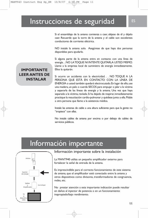
Información importante sobre la instalación
La MANT940 utiliza un pequeño amplificador externo para fortalecer la señal de entrada de la antena.
Es imprescindible para el correcto funcionamiento de este sistemade antena, que el amplificador esté conectado entre la antena yotros dispositivos como divisores, transformadores de congruencia,redes, etc.
No prestar atención a esta importante indicación puede resultaren daños al inyector de potencia o en un funcionamiento inapropiado/bajo rendimiento.
IMPORTANTELEER ANTES DE
INSTALAR
Información importante
MANT940 Instruct Eng Sp_SM 10/8/07 4:38 PM Page 11
ES
12
Piezas incluidas:1. Antena MANT940 . . . . . . . . . . . . . . . . . . . . . . .12. Alimentación 12V a 6VDC . . . . . . . . . . . . . . .13. Soporte de pared/mástil . . . . . . . . . . . . . . . . . .14. Tuercas . . . . . . . . . . . . . . . . . . . . . . . . . . . . . . . .25. Pernos en U . . . . . . . . . . . . . . . . . . . . . . . . . . .2 6. Abrazaderas de mástil . . . . . . . . . . . . . . . . . . . .27. Tuercas con arandelas de cerrojo . . . . . . . . . .48. Soporte en L . . . . . . . . . . . . . . . . . . . . . . . . . . .19. Tornillos para Madera de 2˝ . . . . . . . . . . . . . . .410. Cable coaxial de 20 ft. . . . . . . . . . . . . . . . . . . . .111. Capuchón protector . . . . . . . . . . . . . . . . . . . . .1 12. Inyector de potencia . . . . . . . . . . . . . . . . . . . . .113. Sujetadores plásticos . . . . . . . . . . . . . . . . . . . .4
Antes de la instalación determine el mejor lugar para una recepción óptima. Es importante que la antena tenga una ruta sin obstáculos hacia el transmisor. Para determinar la ubicacióndel transmisor puede consultar la página Web http://www.antennaweb.org. Para obtener los mejores resultadosla antena debe estar enfocada hacia la ubicación del transmisorcomo se muestra abajo.
Instrucciones generales para el armado y montaje de la antena.
Para instalación interior en pared:
NOTA: Realice todas las tareas de ensamblado de la antena en el piso antes de instalar la antena a la pared o el mástil de antena.
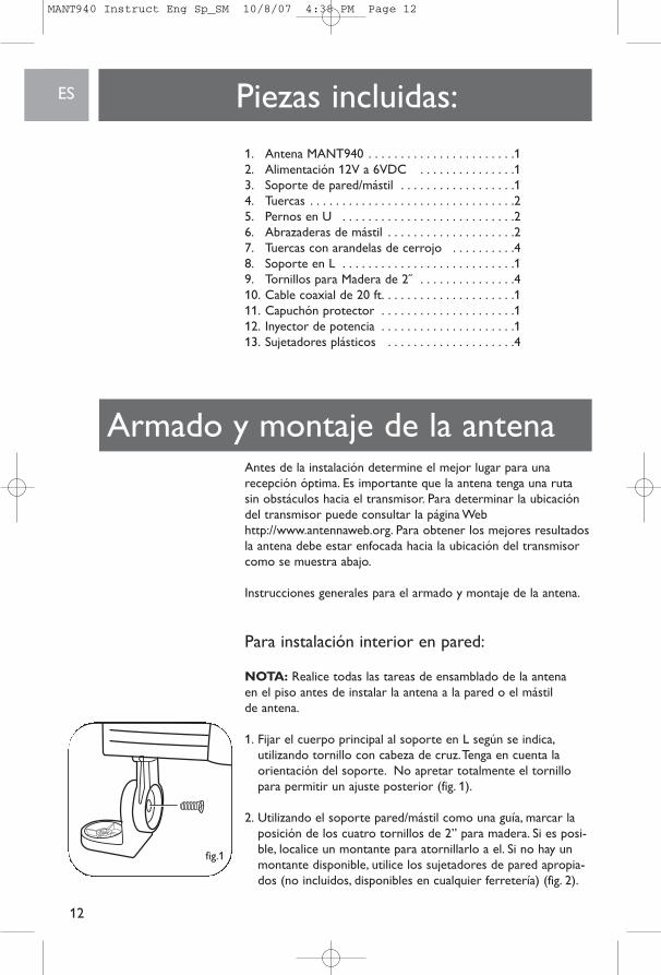
1. Fijar el cuerpo principal al soporte en L según se indica,utilizando tornillo con cabeza de cruz.Tenga en cuenta la orientación del soporte. No apretar totalmente el tornillopara permitir un ajuste posterior (fig. 1).
2. Utilizando el soporte pared/mástil como una guía, marcar laposición de los cuatro tornillos de 2” para madera. Si es posi-ble, localice un montante para atornillarlo a el. Si no hay unmontante disponible, utilice los sujetadores de pared apropia-dos (no incluidos, disponibles en cualquier ferretería) (fig. 2).
Armado y montaje de la antena
fig.1
MANT940 Instruct Eng Sp_SM 10/8/07 4:38 PM Page 12
ES
13
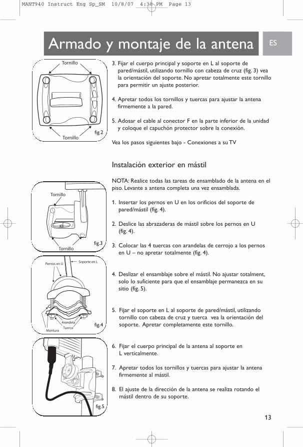
3. Fijar el cuerpo principal y soporte en L al soporte depared/mástil, utilizando tornillo con cabeza de cruz (fig. 3) veala orientación del soporte. No apretar totalmente este tornillopara permitir un ajuste posterior.
4. Apretar todos los tornillos y tuercas para ajustar la antenafirmemente a la pared.
5. Adosar el cable al conector F en la parte inferior de la unidady coloque el capuchón protector sobre la conexión.
Vea los pasos siguientes bajo - Conexiones a su TV
Instalación exterior en mástil
NOTA: Realice todas las tareas de ensamblado de la antena en elpiso. Levante a antena completa una vez ensamblada.
1. Insertar los pernos en U en los orificios del soporte depared/mástil (fig. 4).
2. Deslice las abrazaderas de mástil sobre los pernos en U (fig. 4).
3. Colocar las 4 tuercas con arandelas de cerrojo a los pernosen U – no apretar totalmente (fig. 4).
4. Deslizar el ensamblaje sobre el mástil. No ajustar totalment,solo lo suficiente para que el ensamblaje permanezca en susitio (fig. 5).
5. Fijar el soporte en L al soporte de pared/mástil, utilizandotornillo con cabeza de cruz y tuerca vea la orientación delsoporte. Apretar completamente este tornillo.
6. Fijar el cuerpo principal de la antena al soporte en L verticalmente.
7. Apretar todos los tornillos y tuercas para ajustar la antenafirmemente al mástil.
8. El ajuste de la dirección de la antena se realiza rotando elmástil dentro de su soporte.
Armado y montaje de la antena
fig.2
fig.3
fig.4
fig.5
MANT940 Instruct Eng Sp_SM 10/8/07 4:38 PM Page 13
ES
14
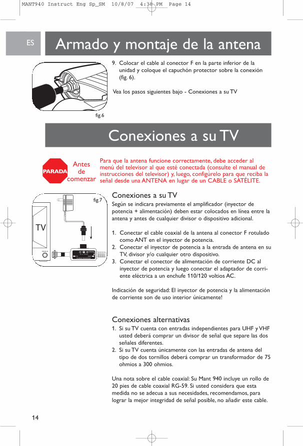
9. Colocar el cable al conector F en la parte inferior de launidad y coloque el capuchón protector sobre la conexión(fig. 6).
Vea los pasos siguientes bajo - Conexiones a su TV
Conexiones a su TVSegún se indicara previamente el amplificador (inyector depotencia + alimentación) deben estar colocados en línea entre laantena y antes de cualquier divisor o dispositivo adicional.
1. Conectar el cable coaxial de la antena al conector F rotuladocomo ANT en el inyector de potencia.
2. Conectar el inyector de potencia a la entrada de antena en suTV, divisor y/o cualquier otro dispositivo.
3. Conectar el conector de alimentación de corriente DC alinyector de potencia y luego conectar el adaptador de corri-ente eléctrica a un enchufe 110/120 voltios AC.
Indicación de seguridad: El inyector de potencia y la alimentaciónde corriente son de uso interior únicamente!
Conexiones alternativas1. Si su TV cuenta con entradas independientes para UHF y VHF
usted deberá comprar un divisor de señal que separe las dosseñales diferentes.
2. Si su TV cuenta únicamente con las entradas de antena deltipo de dos tornillos deberá comprar un transformador de 75ohmios a 300 ohmios.
Una nota sobre el cable coaxial: Su Mant 940 incluye un rollo de20 pies de cable coaxial RG-59. Si usted considera que estamedida no se adecua a sus necesidades, recomendamos, paralograr la mejor integridad de señal posible, no añadir este cable.
Armado y montaje de la antena
Conexiones a su TVfig.6
fig.7
Para que la antena funcione correctamente, debe acceder al menú del televisor al que esté conectada (consulte el manual deinstrucciones del televisor) y, luego, configúrelo para que reciba laseñal desde una ANTENA en lugar de un CABLE o SATÉLITE.
PARADAAntes
de comenzar
MANT940 Instruct Eng Sp_SM 10/8/07 4:38 PM Page 14
ES
15
Una mejor opción es sustituir el cable ya sea con RG-6 o RG-6 con blindaje cuádruple.Ambos cables han sido diseñadospara una pérdida de señal mínima en recorridos de cable más extensos. Esto asegurará la mejor imagen y rendimiento general posibles.
Garantía limitada de por vidaPhilips garantiza que este producto carece de defectos de material,manufactura o armado, bajo uso normal y de acuerdo con las especifi-caciones y advertencias, durante el tiempo que éste sea de supropiedad. Esta garantía cubre únicamente al comprador original delproducto y no es transferible. Para ejercer sus derechos bajo estagarantía, debe proporcionar una prueba de compra mediante una fac-tura original que muestre el nombre del producto y la fecha de com-pra. Por atención al cliente o para obtener servicio de garantía, sírvasellamar al 919-573-7854. NO EXISTEN OTRAS GARANTÍASIMPLÍCITAS O EXPLÍCITAS. Las obligaciones de Philips se limitan a lareparación o, a su sola opción, al reemplazo del producto. No se acep-tan reclamos por daños incidentales, especiales e indirectos, de acuer-do a lo permitido por la ley. Esta garantía le otorga a usted derechoslegales específicos. Usted también tener otros derechos que puedenvariar de estado a estado.
Correo electrónico:[email protected]
©2007Centro de Servicio de AccesoriosPhilips Accessories and Computer Peripherals,Ledgewood, NJ 07852 USA
Calidad comprobada en los EE.UU.
Imprimido en China
Conexiones a su TV
Asistencia Técnica
Garantía
MANT940 Instruct Eng Sp_SM 10/8/07 4:38 PM Page 15

Specifications are subject to change without noticeTrademarks are property of Philips Accessories and Computer Peripherals2007© Philips Accessories and Computer Peripherals, Ledgewood, NJ USA
www.philips.com
MANT940 Instruct Eng Sp_SM 10/8/07 4:38 PM Page 16


![[Care and Use Man Ual ] - Waters Corporation€¦ · · 2012-06-20[Care and Use Man Ual ] XBridge ™ Columns 3 Table 1: Empty Column Volumes in mL (multiply by 10 for flush solvent](https://img.pdfslide.net/doc/110x75/5aef1c417f8b9a572b8da07b/care-and-use-man-ual-waters-2012-06-20care-and-use-man-ual-xbridge-.jpg)