Embed Size (px)
Citation preview
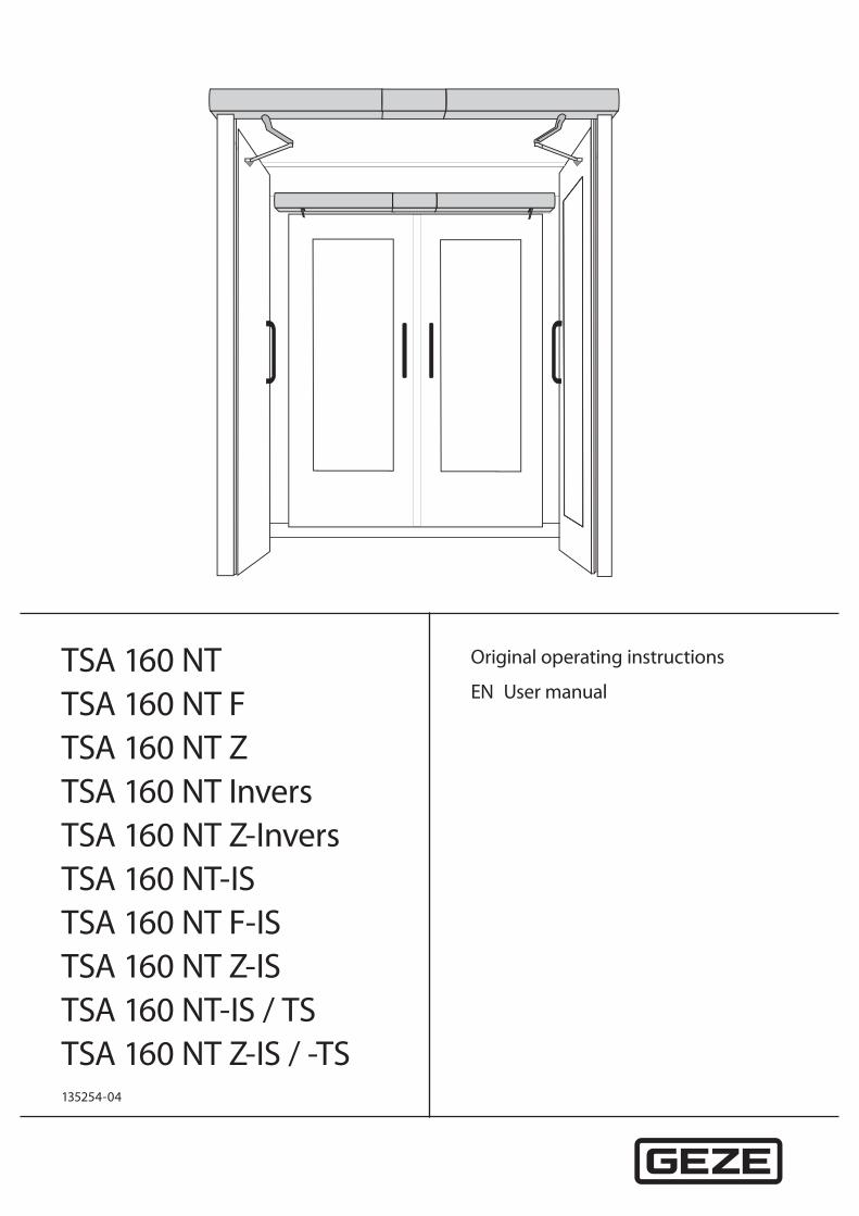
TSA 160 NTTSA 160 NT FTSA 160 NT ZTSA 160 NT InversTSA 160 NT Z-InversTSA 160 NT-ISTSA 160 NT F-ISTSA 160 NT Z-ISTSA 160 NT-IS / TSTSA 160 NT Z-IS / -TS
Original operating instructions
EN User manual
135254-04
TSA 160 NT
2
Contents
1 Introduction...............................................................................................................................................................31.1 Symbols and illustrations ..............................................................................................................................................................................31.2 Product liability .................................................................................................................................................................................................31.3 Special cases .......................................................................................................................................................................................................31.4 More detailed information ............................................................................................................................................................................31.5 Terms .....................................................................................................................................................................................................................4
2 Fundamental safety precautions .......................................................................................................................62.1 For the user .........................................................................................................................................................................................................62.2 For the service technician .............................................................................................................................................................................62.3 Intended use.......................................................................................................................................................................................................6
3 Description .................................................................................................................................................................73.1 Types of installation and versions ..............................................................................................................................................................73.2 Set-up ....................................................................................................................................................................................................................73.3 Overview of the modes of operation ........................................................................................................................................................83.4 Operating elements.........................................................................................................................................................................................83.5 Door in normal operation .......................................................................................................................................................................... 10
4 Operation .................................................................................................................................................................114.1 Selecting the mode of operation .............................................................................................................................................................11
5 Troubleshooting .....................................................................................................................................................13
6 Cleaning and maintenance ................................................................................................................................146.1 Cleaning .............................................................................................................................................................................................................146.2 Maintenance .....................................................................................................................................................................................................146.3 Inspection by an expert ...............................................................................................................................................................................15
7 Technical data .........................................................................................................................................................15
TSA 160 NT
3
Introduction
1 Introduction
1.1 Symbols and illustrations
Warning noticesWarning notices are used in these instructions to warn you of property damage and personal injury.
X Always read and observe these warning notices. X Observe all measures marked with the warning symbol and warning word .
Warning symbol Warning word Meaning
CAUTION Danger to persons. Non-compliance can result in minor to medium injuries.
Further symbols and illustrationsImportant information and technical notes are highlighted to explain correct operation.
Symbol Meaning
means “important note”; information about avoiding property damage
means “additional Information”The user's attention should be drawn to important addition information. There is no danger to persons or property, but it is particularly useful to read the additional information carefully.
X Symbol for an action: This means you have to do something.
X If there are several actions to be taken, keep to the given order.
1.2 Product liabilityIn compliance with the liability of the manufacturer for his products as defined in the German “Product Liability Act”, compliance with the information contained in this brochure (product information and intended use, misuse, product performance, product maintenance, obligations to provide information and instructions) must be en-sured. Failure to comply releases the manufacturer from his statutory liability.
1.3 Special casesIn certain cases, deviations from the information given in this user manual may occur. Examples: à special wiring à special function settings (parameters) à special software X Please contact the service technician responsible for further information.
1.4 More detailed informationInformation about commissioning and service can be found in the following documents: à wiring diagram TSA 160 NT à installation instructions TSA 160 NT
TSA 160 NT
4
Introduction
1.5 TermsTerm ExplanationHinge side The side of the door where the hinges from which the door leaf is suspended are located.
Usually that side of the door located in the opening direction.Opposite hinge side The side of the door facing the hinge side. Usually that side of the door located in the direc-
tion of closing movement.Active leaf The active leaf of a double-leaf door. When the door is used, the active leaf must open as
the first door leaf and close as the last door leaf.Passive leaf The secondary leaf of a double-leaf door. When the door is used, the passive leaf may not open
until the active leaf has left the closing position and must close again as the first door leaf.Activation device - inside (KI) Push button, switch or movement detector for activating the door drive.
The activation device is located within the room enclosed by the door.Activation function in the modes of operation AUTOMATIC and EXIT ONLY 1).The activation device does not have any function in the NIGHT/OFF mode of operation.
Activation device - out-side (KA)
Push button, switch or movement detector for activating the door drive.The activation device is located outside the room enclosed by the door.Activation function in the AUTOMATIC mode of operation. The activation device does not have any function in the EXIT ONLY 1) and NIGHT/OFF modes of operation.
Activation device authorised (KB)
Access control function (for example key switch or card reader) used by authorised persons to activate the door drive.The control function is active in the AUTOMATIC, EXIT ONLY1) and NIGHT/OFF modes of operation.
Activation device with current impulse function
Push button for opening and closing the door. Control function only in the AUTOMATIC and EXIT ONLY modes of operation1). The door is opened automatically when the button is first pressed and closed again automatically when the button is pressed the second time. The function can be activated during commissioning by parameter setting.
Push&Go When the door is pressed manually out of the closing position during an activated closing position inhibition, the door opens automatically as soon as a specific adjustable opening angle is exceeded.
Opening safety sensor (SIO) Presence detector (e.g. active infrared light switch) for protecting the swinging range of the door in the opening direction. As a rule the sensor is located on the hinge side of the door on the door leaf.
Closing safety sensor (SIS) Presence detector (for example active infrared light switch) for protecting the swinging range of the door in the closing direction. As a rule the sensor is located on the opposite hinge side of the door leaf.
Stop Self-locking switch with which immediate stopping of the door drive can be triggered in case of danger. The door drive remains in its current position until the user unlocks the stop switch again, thus terminating the stop situation.
Closing sequence control Electrical closing sequence control In normal operation of double-leaf door drives, the closing sequence of the door leaves is controlled by the control units of the door drives, with the passive leaf being closed first. The active leaf remains in the open position until the hold-open time of the passive leaf has expired. Only then does the active leaf begin to close.Integrated closing sequence control (-IS): In the event of a power failure for 2-leaf door systems, the closing sequence is controlled mechanically with TSA 160 NT-F-IS. The door leaves are closed by means of the power stor-age of the drives, with the active leaf being kept open by the integrated mechanical closing sequence control unit at approximately 30° opening angle before the closing position is reached. When the passive leaf has reached the closing position, it releases the active leaf by means of the mechanical elements of the integrated closing sequence control so that it can also close completely..
1) The EXIT ONLY mode of operation can only be selected with the optional mechanical programme switch.
TSA 160 NT
5
Introduction
Term ExplanationElectric strike Fail-secure electric strike
Available as AC or DC electric strike version. When the door drive is activated, the electric strike is switched on by the control unit of the door drive provided the door is in the closing position. The electric strike remains activated until the door has left the closing position.Fail-safe electric strikeDC electric strike version. The electric strike is switched off when the door drive is activated provided the door is in the closing position. The electric strike remains switched off until the door has left the closing position.
Bar feedback The bar feedback function is a contact integrated in the door catch that is activated when the door is locked mechanically by the tie bolt of the door lock. It signals to the control unit that the door is locked mechanically and can therefore not be opened by the door drive. In this case the control unit ignores the control commands of all the activation devices.
Reset Push button for restarting the drive after the operating voltage has been switched on or after a fire alarm has been terminated. When the push button is pressed, the self-retention integrated in the drive is activated, causing the drive to be activated.
Latching function When the door is closed in a de-energised state, the door leaf is impeded by the lock latch of the electric strike. To make sure the door can pass the lock latch safely during closing, an integrated limit switch is activated in the drive once a specific opening angle has been reached, reducing the braking strength. The door accelerates and closes into the lock at increased speed. In an energised state, this function is regulated by the drive control unit.
TSA 160 NT
6
Fundamental safety precautions
2 Fundamental safety precautions
2.1 For the userCarefully read and abide by this user manual before commissioning the door. Always observe the following safety instructions: à Operating, maintenance and repair conditions specified by GEZE must be observed. à The commissioning, mandatory installation, maintenance and repair work must be performed by experts
authorised by GEZE. à The connection to the mains voltage must be made by a professional electrician. à No changes may be made to the system without prior agreement from GEZE. à GEZE shall assume no liability for damage caused by unauthorised changes to the system. à The owner is responsible for safe operation of the system. à Have a service technician check the safe operation of the system at regular intervals. à Should safety devices be misaligned, thus preventing them from fulfilling their intended purpose, further
operation is not permissible. The service technician must be informed without delay. à Make sure that the safety stickers are attached visibly to any glass leaves and are in a legible state. à Protect the programme switch against unauthorised access. à Danger of injury by sharp edges on the drive when removing the cover à Danger of injury by parts hanging down à This appliance can be used by children aged from 8 years and above and persons with reduced physical,
sensory or mental capabilities or lack of experience and knowledge if they have been given supervision or instruction concerning use of the appliance in a safe way and understand the hazards involved.
à Children shall not play with the appliance. à Cleaning and user maintenance shall not be made by children without supervision.
2.2 For the service technician à GEZE does not accept any warranty for combinations with third-party products. à Only combine third-party products with original parts following agreement by GEZE. Furthermore, only origi-
nal GEZE parts may be used for repair and maintenance work. à The power connection and safety earth conductor test must be carried out in accordance DIN VDE 0100-610. à Use a customer-accessible 16-A overload cut-out that disconnects the system from the power supply as the
line-side disconnecting device.
2.3 Intended useThe TSA 160 NT swing door drives are designed for the automatic opening and closing of single action swing doors.
The above mentioned door drive is suitable à solely for use in dry rooms à in entrances and indoor areas of pedestrian traffic on commercial premises and in public areas à in private areas
The TSA 160 NT / TSA 160 NT IS/TS door drive à may be used in escape and rescue routes à must not be used on fire or smoke protection doors à must not be used for potentially explosive areas.
The TSA 160 NT F/ TSA 160 NT F-IS door drive à may be used in escape and rescue routes à may be used on fire or smoke protection doors à must not be used for potentially explosive areas.
The TSA 160 NT Invers door drive à is designed mainly for use on escape route doors and smoke and heat extraction system doors à must not be used for potentially explosive areas.
TSA 160 NT
7
Description
3 Description
3.1 Types of installation and versions
System parts and options à The door drive can be fitted in transom installation on the lintel on the hinge side or opposite hinge side. à The door drive is available as 1-leaf or 2-leaf version. à The TSA 160 NT F-IS and TSA 160 NT IS/TS systems can only be fitted in transom installation.
3.2 Set-up
The door system shown is only a schematic diagram.For technical reasons, we cannot show all of the possibilities here.The operating elements can be arranged individually.
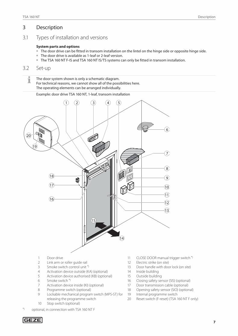
Example: door drive TSA 160 NT, 1-leaf, transom installation
1 Door drive2 Link arm or roller guide rail3 Smoke switch control unit *) 4 Activation device outside (KA) (optional)5 Activation device authorised (KB) (optional)6 Smoke switch *) 7 Activation device inside (KI) (optional)8 Programme switch (optional)9 Lockable mechanical program switch (MPS-ST) for
releasing the programme switch10 Stop switch (optional)
11 CLOSE DOOR manual trigger switch *)
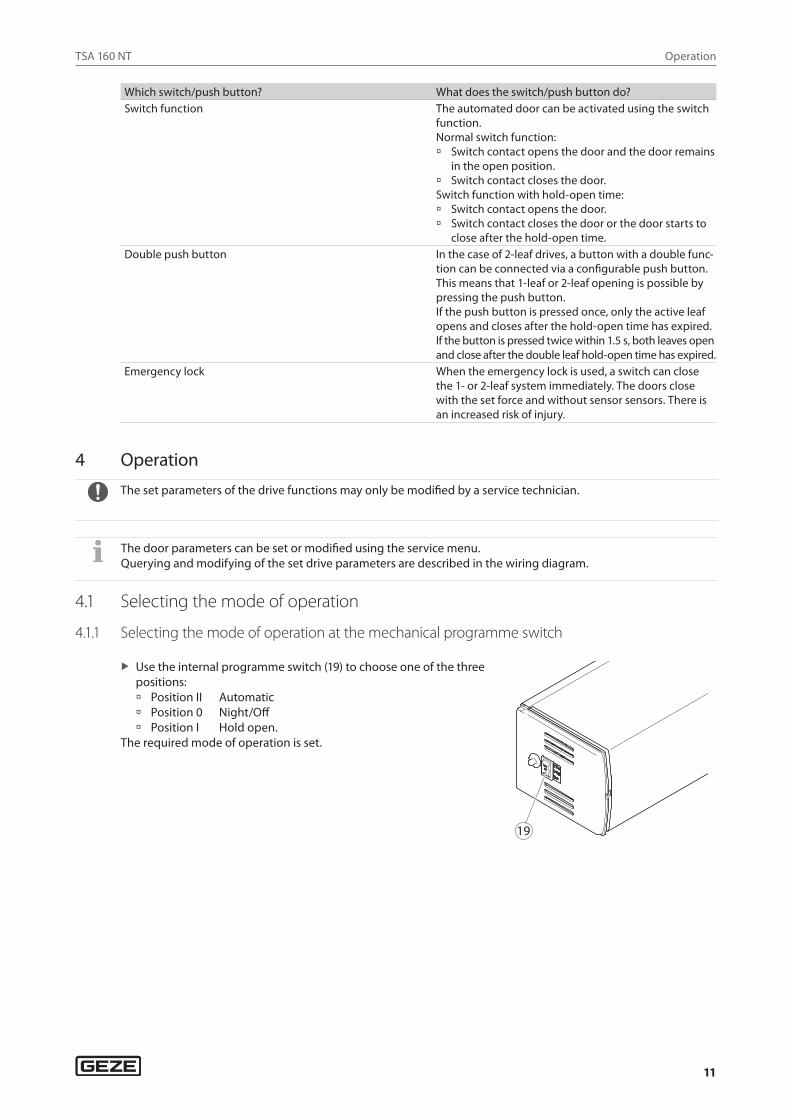
12 Electric strike (on site)13 Door handle with door lock (on site)14 Inside building15 Outside building 16 Closing safety sensor (SIS) (optional)17 Door transmission cable (optional)18 Opening safety sensor (SIO) (optional)19 Internal programme switch20 Reset switch (F-reset) (TSA 160 NT F only)
*) optional, in connection with TSA 160 NT F
TSA 160 NT
8
Description
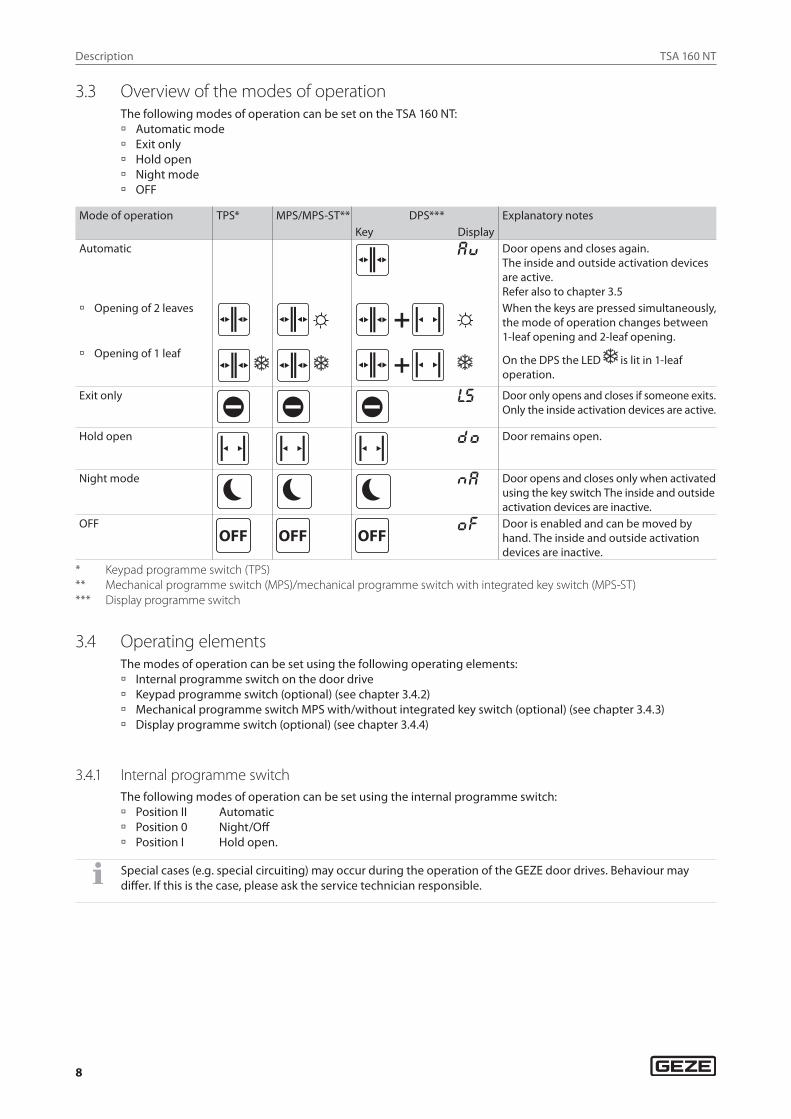
3.3 Overview of the modes of operationThe following modes of operation can be set on the TSA 160 NT: à Automatic mode à Exit only à Hold open à Night mode à OFF
Mode of operation TPS* MPS/MPS-ST** DPS*** Explanatory notesKey Display
Automatic aU Door opens and closes again.The inside and outside activation devices are active.Refer also to chapter 3.5
à Opening of 2 leaves When the keys are pressed simultaneously, the mode of operation changes between 1-leaf opening and 2-leaf opening.
à Opening of 1 leaf On the DPS the LED is lit in 1-leaf operation.
Exit only ls Door only opens and closes if someone exits.Only the inside activation devices are active.
Hold open DO Door remains open.
Night mode Na Door opens and closes only when activated using the key switch The inside and outside activation devices are inactive.
OFFOFF OFF OFF
Of Door is enabled and can be moved by hand. The inside and outside activation devices are inactive.
* Keypad programme switch (TPS)** Mechanical programme switch (MPS)/mechanical programme switch with integrated key switch (MPS-ST)*** Display programme switch
3.4 Operating elementsThe modes of operation can be set using the following operating elements: à Internal programme switch on the door drive à Keypad programme switch (optional) (see chapter 3.4.2) à Mechanical programme switch MPS with/without integrated key switch (optional) (see chapter 3.4.3) à Display programme switch (optional) (see chapter 3.4.4)
3.4.1 Internal programme switchThe following modes of operation can be set using the internal programme switch: à Position II Automatic à Position 0 Night/Off à Position I Hold open.
Special cases (e.g. special circuiting) may occur during the operation of the GEZE door drives. Behaviour may differ. If this is the case, please ask the service technician responsible.
TSA 160 NT
9
Description
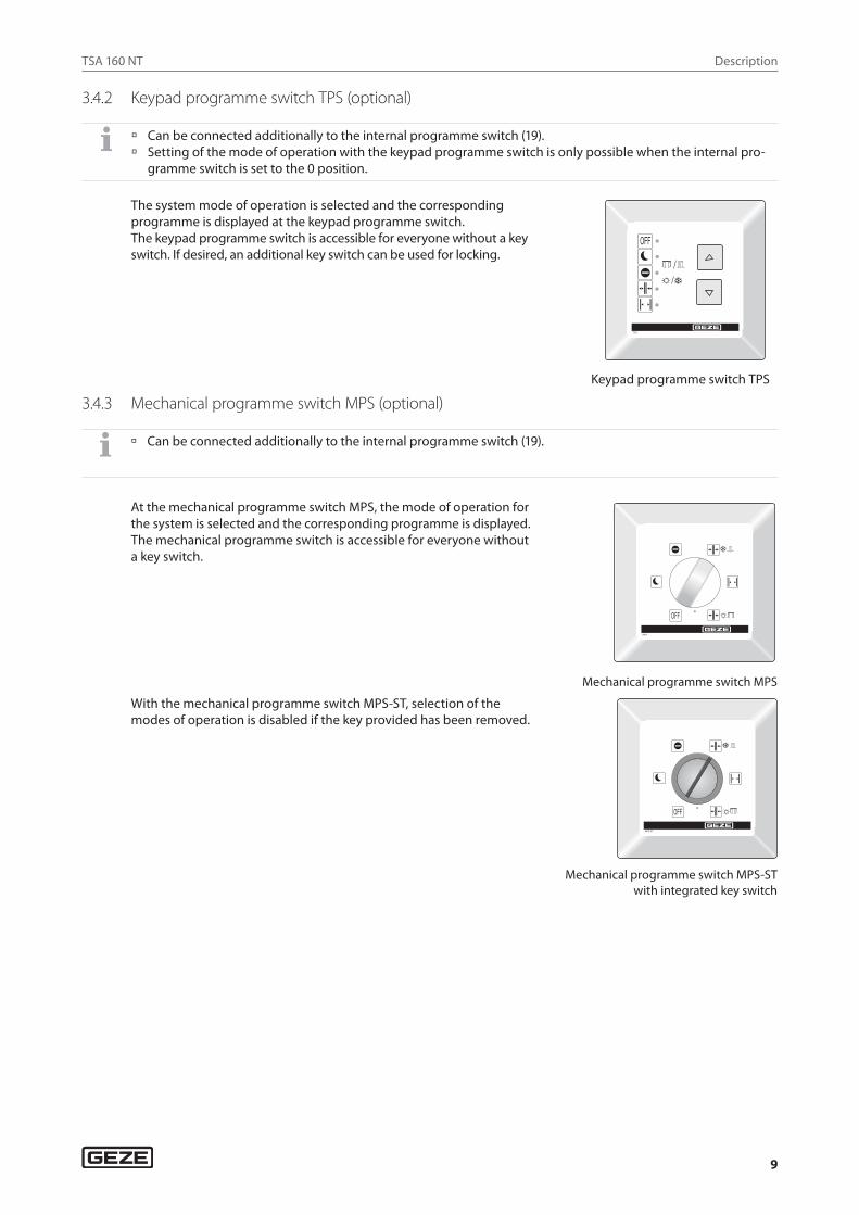
3.4.2 Keypad programme switch TPS (optional)
à Can be connected additionally to the internal programme switch (19). à Setting of the mode of operation with the keypad programme switch is only possible when the internal pro-
gramme switch is set to the 0 position.
The system mode of operation is selected and the corresponding programme is displayed at the keypad programme switch.The keypad programme switch is accessible for everyone without a key switch. If desired, an additional key switch can be used for locking.
Keypad programme switch TPS
3.4.3 Mechanical programme switch MPS (optional)
à Can be connected additionally to the internal programme switch (19).
At the mechanical programme switch MPS, the mode of operation for the system is selected and the corresponding programme is displayed.The mechanical programme switch is accessible for everyone without a key switch.
Mechanical programme switch MPS
With the mechanical programme switch MPS-ST, selection of the modes of operation is disabled if the key provided has been removed.
Mechanical programme switch MPS-ST with integrated key switch
TSA 160 NT
10
Description
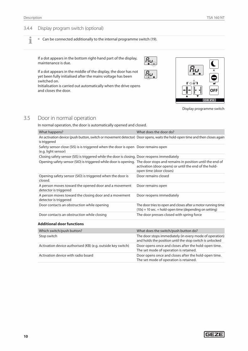
3.4.4 Display program switch (optional)
à Can be connected additionally to the internal programme switch (19).
If a dot appears in the bottom right-hand part of the display, maintenance is due.
OFF
Display programme switch
If a dot appears in the middle of the display, the door has not yet been fully initialised after the mains voltage has been switched on.Initialisation is carried out automatically when the drive opens and closes the door.
3.5 Door in normal operationIn normal operation, the door is automatically opened and closed.
What happens? What does the door do?An activation device (push button, switch or movement detector) is triggered
Door opens, waits the hold-open time and then closes again
Safety sensor close (SIS) is is triggered when the door is open (e.g. light sensor)
Door remains open
Closing safety sensor (SIS) is triggered while the door is closing. Door reopens immediatelyOpening safety sensor (SIO) is triggered while door is opening. The door stops and remains in position until the end of
activation (door opens) or until the end of the hold-open time (door closes)
Opening safety sensor (SIO) is triggered when the door is closed.
Door remains closed
A person moves toward the opened door and a movement detector is triggered
Door remains open
A person moves toward the closing door and a movement detector is triggered
Door reopens immediately
Door contacts an obstruction while opening The door tries to open and closes after a motor running time (10s) + 10 sec. + hold-open time (depending on setting)
Door contacts an obstruction while closing The door presses closed with spring force
Additional door functions
Which switch/push button? What does the switch/push button do?Stop switch The door stops immediately (in every mode of operation)
and holds the position until the stop switch is unlockedActivation device authorised (KB) (e.g. outside key switch) Door opens once and closes after the hold-open time.
The set mode of operation is retained.Activation device with radio board Door opens once and closes after the hold-open time.
The set mode of operation is retained.
TSA 160 NT
11
Operation
Which switch/push button? What does the switch/push button do?Switch function The automated door can be activated using the switch
function.Normal switch function: à Switch contact opens the door and the door remains
in the open position. à Switch contact closes the door.
Switch function with hold-open time: à Switch contact opens the door. à Switch contact closes the door or the door starts to
close after the hold-open time.Double push button In the case of 2-leaf drives, a button with a double func-
tion can be connected via a configurable push button. This means that 1-leaf or 2-leaf opening is possible by pressing the push button. If the push button is pressed once, only the active leaf opens and closes after the hold-open time has expired. If the button is pressed twice within 1.5 s, both leaves open and close after the double leaf hold-open time has expired.
Emergency lock When the emergency lock is used, a switch can close the 1- or 2-leaf system immediately. The doors close with the set force and without sensor sensors. There is an increased risk of injury.
4 Operation
The set parameters of the drive functions may only be modified by a service technician.
The door parameters can be set or modified using the service menu.Querying and modifying of the set drive parameters are described in the wiring diagram.
4.1 Selecting the mode of operation
4.1.1 Selecting the mode of operation at the mechanical programme switch
X Use the internal programme switch (19) to choose one of the three positions: à Position II Automatic à Position 0 Night/Off à Position I Hold open.
The required mode of operation is set.
��
TSA 160 NT
12
Operation
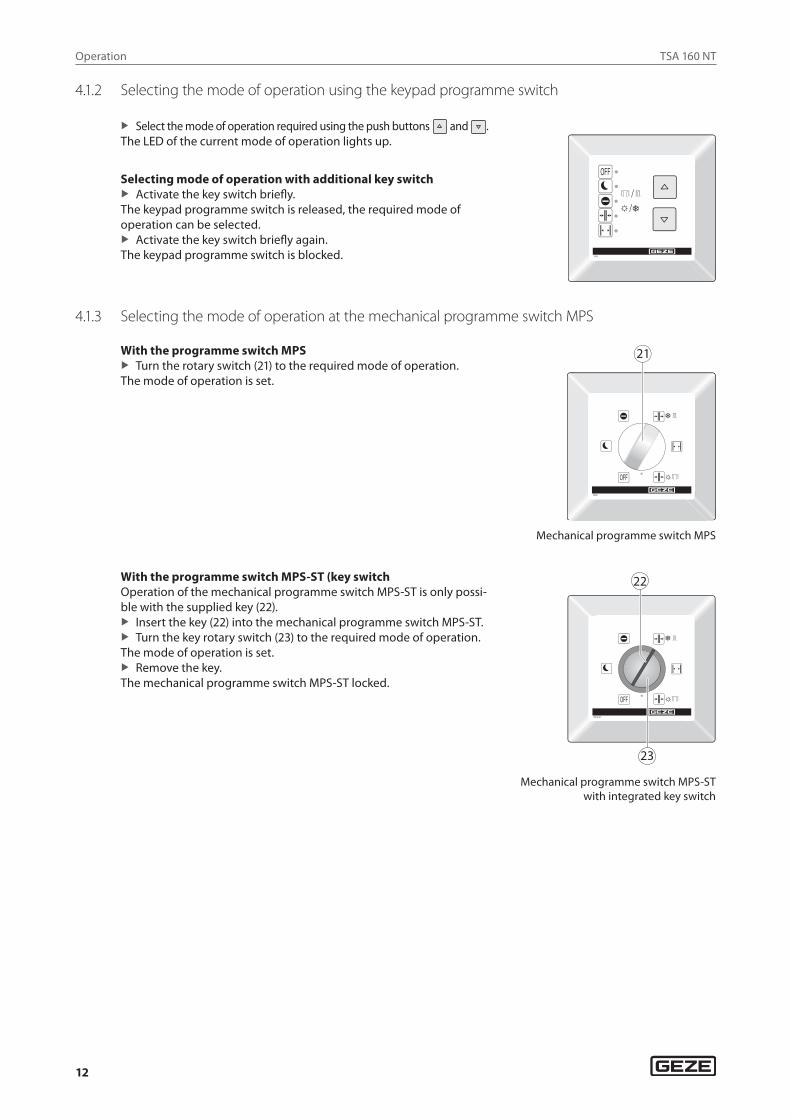
4.1.2 Selecting the mode of operation using the keypad programme switch
X Select the mode of operation required using the push buttons and . The LED of the current mode of operation lights up.
Selecting mode of operation with additional key switch X Activate the key switch briefly.
The keypad programme switch is released, the required mode of operation can be selected.
X Activate the key switch briefly again. The keypad programme switch is blocked.
4.1.3 Selecting the mode of operation at the mechanical programme switch MPS
With the programme switch MPS X Turn the rotary switch (21) to the required mode of operation.
The mode of operation is set.
21
Mechanical programme switch MPS
With the programme switch MPS-ST (key switchOperation of the mechanical programme switch MPS-ST is only possi-ble with the supplied key (22).
X Insert the key (22) into the mechanical programme switch MPS-ST. X Turn the key rotary switch (23) to the required mode of operation.
The mode of operation is set. X Remove the key.
The mechanical programme switch MPS-ST locked.
��
��
Mechanical programme switch MPS-ST with integrated key switch
TSA 160 NT
13
Troubleshooting
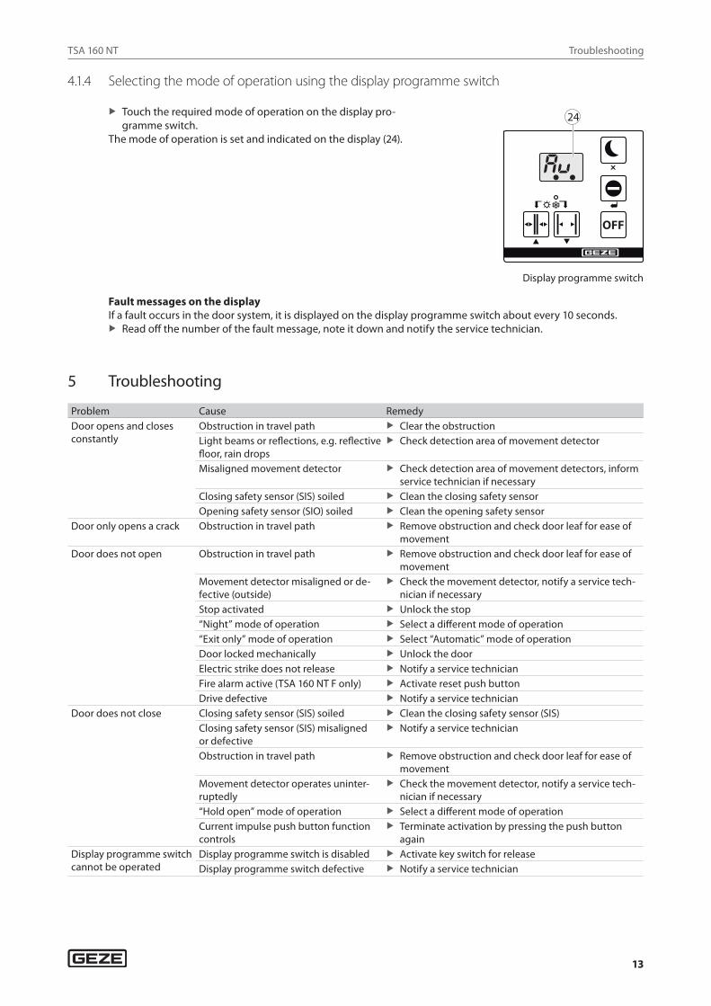
4.1.4 Selecting the mode of operation using the display programme switch
X Touch the required mode of operation on the display pro-gramme switch.
The mode of operation is set and indicated on the display (24).
OFF
24
Display programme switch
Fault messages on the displayIf a fault occurs in the door system, it is displayed on the display programme switch about every 10 seconds.
X Read off the number of the fault message, note it down and notify the service technician.
5 Troubleshooting
Problem Cause RemedyDoor opens and closes constantly
Obstruction in travel path X Clear the obstructionLight beams or reflections, e.g. reflective floor, rain drops
X Check detection area of movement detector
Misaligned movement detector X Check detection area of movement detectors, inform service technician if necessary
Closing safety sensor (SIS) soiled X Clean the closing safety sensorOpening safety sensor (SIO) soiled X Clean the opening safety sensor
Door only opens a crack Obstruction in travel path X Remove obstruction and check door leaf for ease of movement
Door does not open Obstruction in travel path X Remove obstruction and check door leaf for ease of movement
Movement detector misaligned or de-fective (outside)
X Check the movement detector, notify a service tech-nician if necessary
Stop activated X Unlock the stop“Night” mode of operation X Select a different mode of operation“Exit only” mode of operation X Select “Automatic” mode of operationDoor locked mechanically X Unlock the doorElectric strike does not release X Notify a service technicianFire alarm active (TSA 160 NT F only) X Activate reset push buttonDrive defective X Notify a service technician
Door does not close Closing safety sensor (SIS) soiled X Clean the closing safety sensor (SIS)Closing safety sensor (SIS) misaligned or defective
X Notify a service technician
Obstruction in travel path X Remove obstruction and check door leaf for ease of movement
Movement detector operates uninter-ruptedly
X Check the movement detector, notify a service tech-nician if necessary
“Hold open” mode of operation X Select a different mode of operationCurrent impulse push button function controls
X Terminate activation by pressing the push button again
Display programme switch cannot be operated
Display programme switch is disabled X Activate key switch for releaseDisplay programme switch defective X Notify a service technician
TSA 160 NT
14
Cleaning and maintenance
Problem Cause RemedyDisplay programme switch displays 8 8
Connection between display pro-gramme switch and control unit faulty
X Notify a service technician
Display programme switch or control unit defective
X Notify a service technician
Display programme switch is dark
Mains power failure X Check mains fuseConnection between display pro-gramme switch and control unit faulty
X Notify a service technician
Display programme switch or control unit defective
X Notify a service technician
Display of fault messages on the display programme switch
Fault in the door system X Note fault messages. Up to 10 different fault messag-es can occur in succession. The display changes about every 10 seconds.
X Notify a service technician
6 Cleaning and maintenance
CAUTION! Danger of injury due to impact and crushing.
X Disconnect the drive from the 230 V mains network before carrying out cleaning work. X Secure door leaves against accidental movement before carrying out cleaning work.
6.1 CleaningWhat is to be cleaned? How is it to be cleaned?Optical safety sensors (e.g. light switches) Wipe with moist cloth.Glass surfaces Wipe with a cold vinegar/water mixture; then dry.Stainless surfaces Wipe with non-scratching cloth.Coated surfaces Wipe with water and soap.Anodised surfaces Wipe with non-alkaline potassium soap (pH value 5.5…7)Mechanical programme switch Wipe with damp cloth. Do not use a cleaning agent..
6.2 MaintenanceThe owner must ensure that the system is working perfectly. To guarantee perfect operation, the door system must be serviced regularly by a service technician.Maintenance must be carried out at least once a year or according to the maintenance display on the display programme switch.Installation, maintenance and repair work must be performed by experts authorised by GEZE.
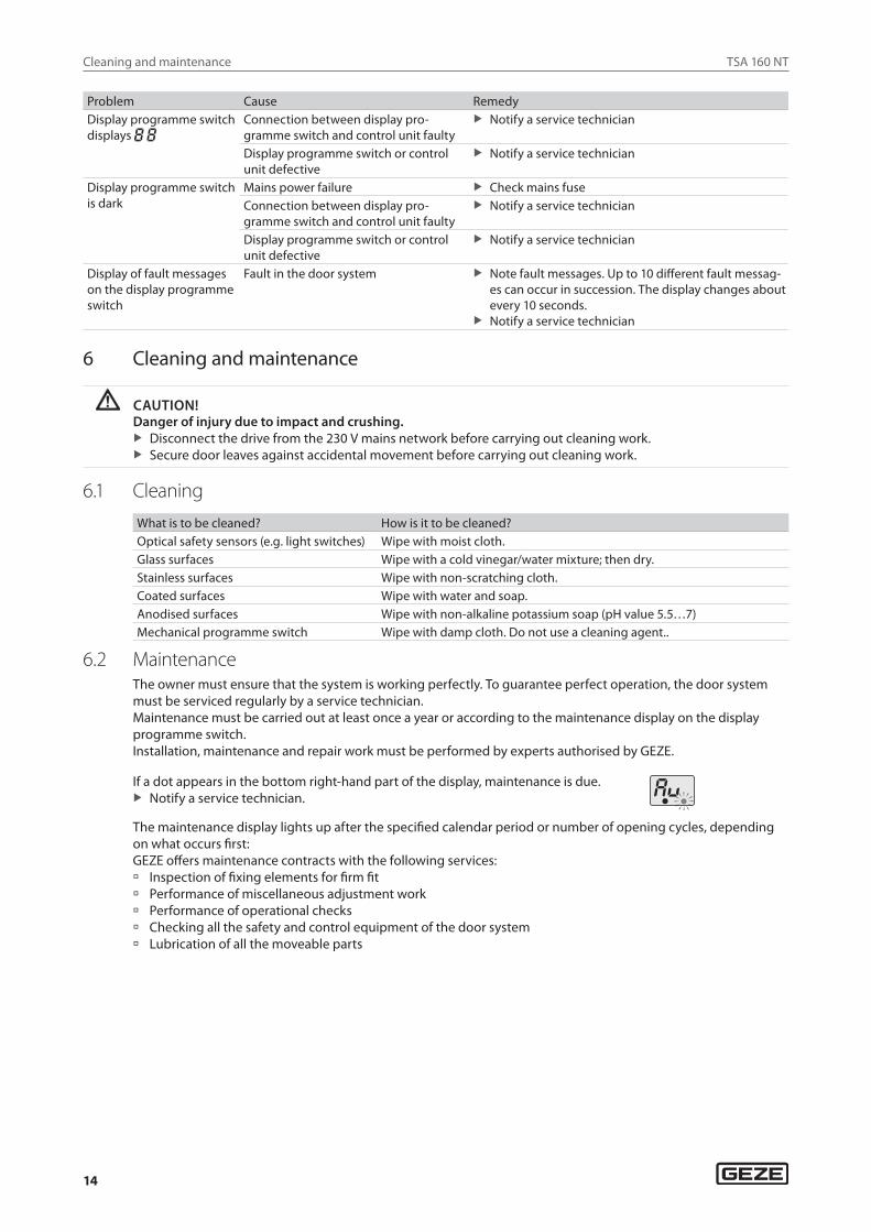
If a dot appears in the bottom right-hand part of the display, maintenance is due. X Notify a service technician.
The maintenance display lights up after the specified calendar period or number of opening cycles, depending on what occurs first:GEZE offers maintenance contracts with the following services: à Inspection of fixing elements for firm fit à Performance of miscellaneous adjustment work à Performance of operational checks à Checking all the safety and control equipment of the door system à Lubrication of all the moveable parts
TSA 160 NT
15
Technical data
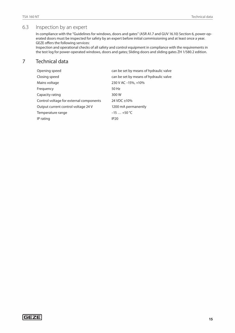
6.3 Inspection by an expertIn compliance with the “Guidelines for windows, doors and gates” (ASR A1.7 and GUV 16.10) Section 6, power-op-erated doors must be inspected for safety by an expert before initial commissioning and at least once a year.GEZE offers the following services:Inspection and operational checks of all safety and control equipment in compliance with the requirements in the test log for power-operated windows, doors and gates; Sliding doors and sliding gates ZH 1/580.2 edition.
7 Technical data
Opening speed can be set by means of hydraulic valve
Closing speed can be set by means of hydraulic valve
Mains voltage 230 V AC –15%, +10%
Frequency 50 Hz
Capacity rating 300 W
Control voltage for external components 24 VDC ±10%
Output current control voltage 24 V 1200 mA permanently
Temperature range –15 … +50 °C
IP rating IP20
GermanyGEZE GmbHNiederlassung Süd-WestTel. +49 (0) 7152 203 594E-Mail: [email protected]
GEZE GmbHNiederlassung Süd-OstTel. +49 (0) 7152 203 6440E-Mail: [email protected]
GEZE GmbHNiederlassung OstTel. +49 (0) 7152 203 6840E-Mail: [email protected]
GEZE GmbHNiederlassung Mitte/LuxemburgTel. +49 (0) 7152 203 6888E-Mail: [email protected]
GEZE GmbHNiederlassung WestTel. +49 (0) 7152 203 6770 E-Mail: [email protected]
GEZE GmbHNiederlassung NordTel. +49 (0) 7152 203 6600E-Mail: [email protected]
GEZE Service GmbHTel. +49 (0) 1802 923392E-Mail: [email protected]
AustriaGEZE AustriaE-Mail: [email protected]
Baltic StatesGEZE GmbH Baltic States officeE-Mail: [email protected]
BeneluxGEZE Benelux B.V.E-Mail: [email protected]
BulgariaGEZE Bulgaria - Trade E-Mail: [email protected]
ChinaGEZE Industries (Tianjin) Co., Ltd.E-Mail: [email protected]
GEZE Industries (Tianjin) Co., Ltd.Branch Office ShanghaiE-Mail: [email protected]
GEZE Industries (Tianjin) Co., Ltd.Branch Office GuangzhouE-Mail: [email protected]
GEZE Industries (Tianjin) Co., Ltd.Branch Office BeijingE-Mail: [email protected]
FranceGEZE France S.A.R.L.E-Mail: [email protected]
HungaryGEZE Hungary Kft.E-Mail: [email protected]
IberiaGEZE Iberia S.R.L.E-Mail: [email protected]
IndiaGEZE India Private Ltd.E-Mail: [email protected]
ItalyGEZE Italia S.r.lE-Mail: [email protected]
GEZE Engineering Roma S.r.lE-Mail: [email protected]
PolandGEZE Polska Sp.z o.o.E-Mail: [email protected]
RomaniaGEZE Romania S.R.L.E-Mail: [email protected]
RussiaOOO GEZE RUSE-Mail: [email protected]
Scandinavia – SwedenGEZE Scandinavia ABE-Mail: [email protected]
Scandinavia – NorwayGEZE Scandinavia AB avd. NorgeE-Mail: [email protected]
Scandinavia – DenmarkGEZE DanmarkE-Mail: [email protected]
SingaporeGEZE (Asia Pacific) Pte, Ltd.E-Mail: [email protected]
South AfricaGEZE South Africa (Pty) Ltd.E-Mail: [email protected]
SwitzerlandGEZE Schweiz AGE-Mail: [email protected]
TurkeyGEZE Kapı ve Pencere SistemleriE-Mail: [email protected]
UkraineLLC GEZE UkraineE-Mail: [email protected]
United Arab Emirates/GCCGEZE Middle EastE-Mail: [email protected]
United KingdomGEZE UK Ltd.E-Mail: [email protected]
GEZE GmbHReinhold-Vöster-Straße 21–2971229 LeonbergGermany
Tel.: 0049 7152 203 0Fax.: 0049 7152 203 310www.geze.com