Embed Size (px)
Citation preview
1Enabling Technologies for 3GPPLTE-Advanced Networks
Narcis Cardona, Jose F. Monserrat and Jorge CabrejasUniversitat Politecnica de Valencia, Spain
The specifications of Long Term Evolution (LTE) in 3rd Generation Partnership Project(3GPP) (Release 8) were just finished when work began on the new Long Term Evolu-tion Advanced (LTE-A) standard (Release 9 and beyond). LTE-A meets or exceeds therequirements imposed by International Telecommunication Union (ITU) to Fourth Gener-ation (4G) mobile systems, also called International Mobile Telecommunication Advanced(IMT-A). These requirements were unthinkable a few years ago, but are now a reality.Peak data rates of 1 Gbps with bandwidths of 100 MHz for the downlink, very lowlatency, more efficient interference management and operational cost reduction are clearexamples of why LTE-A is so appealing for operators. Moreover, the quality breakthroughaffects not only operators but also end users, who are going to experience standards ofquality similar to optical fiber. To reach these levels of capacity and quality, the interna-tional scientific community, in particular the 3GPP, are developing different technologicalenhancements on LTE. The most important technological proposals for LTE-A are: sup-port of wider bandwidth (carrier aggregation), advanced Multiple Input Multiple Output(MIMO) techniques, Coordinated Multipoint transmission or reception (CoMP), relaying,enhancements for Home eNodeB (HeNB) and machine-type communications. To analyzeboth the context of LTE-A and the new enabling technologies, this chapter is dividedas follows:
• Section 1.1: This section introduces LTE-A as an IMT-A technology.• Section 1.2: This section summarizes the main IMT-A features and its requirements in
terms of services, spectrum and performance.• Section 1.3: This section highlights LTE-A requirements. From a direct comparison with
the previous section, it is shown that they are more challenging than those establishedby the ITU for IMT-A.
LTE-Advanced and Next Generation Wireless Networks: Channel Modelling and Propagation, First Edition.Edited by Guillaume de la Roche, Andres Alayon Glazunov and Ben Allen.© 2013 John Wiley & Sons, Ltd. Published 2013 by John Wiley & Sons, Ltd.
COPYRIG
HTED M
ATERIAL
4 LTE-Advanced and Next Generation Wireless Networks
• Section 1.4: This section shows the technological proposals being studied in 3GPP:carrier aggregation, new transmission schemes in both uplink and downlink, CoMP,the use of relays, enhancements for HeNB and machine-type communications and otherimprovements related to the reduction of latency in the user and control plane.
1.1 Introduction
Along its standardization LTE was designed as an evolution of legacy Third Generation(3G) mobile systems due to the incorporation of a set of technological improvements,such as:
• Dynamic allocation of variable bandwidth.• New MIMO schemes.• New transmission schemes with multiple carriers, like Orthogonal Frequency Division
Multiplexing (OFDM) in the DownLink (DL) and DFT Spread- OFDM (DFTS-OFDM),also known as Single Carrier Frequency Division Multiple Access (SC-FDMA), in theUpLink (UL).
• Very low latency in the user and control plane.
All these new features represent a qualitative and quantitative leap in system perfor-mance that is motivated by different reasons. Market globalization and liberalization andthe increasing competence among vendors and operators coming from this new frameworkhas led to the emergence of new technologies. This fact comes together with the popular-ization of Institute of Electrical & Electronics Engineers (IEEE) 802 technologies withinthe mobile communications sector. Finally, end users are becoming more discerning anddemand new and better services such as Voice over IP (VoIP), video-conference, Push-to-talk over Cellular (PoC), multimedia messaging, multiplayer games, audio and videostreaming, content download of ring tones, video clips, virtual private network connec-tions, web browsing, email access, file transfer, and so on. It is precisely this increasingmarket demand and its enormous economic benefits, together with the new challengesthat come with the requirements in higher spectral efficiency and services aggregation thatraised the need to allocate new frequency channels to mobile communications systems.That is why the International Telecommunication Union – Radiocommunication Sector(ITU-R) WP 8F started in October 2005 the definition of the future 4G, also known asIMT-A, following the same model of global standardization used with 3G systems. Theobjective of IMT-A is to specify a set of requirements in terms of transmission capac-ity and quality of service, in such a way that if a certain technology fulfils all theserequirements it is included by the ITU in the IMT-A set of standards. This inclusionfirstly endorses technologies and motivates operators to invest in them, but furthermoreit allows these standards to make use of the frequency bands specially designated forIMT-A, which entails a great motivation for mobile operators to increase their offeredservices and transmission capacity. Given this economic outlook, the 3GPP establishedthe LTE standardization activity as an ongoing task to build up a framework for the evo-lution of the 3GPP radio technologies, concretely Universal Mobile TelecommunicationSystem (UMTS), towards 4G. The 3GPP divided this work into two phases: the formerconcerns the completion of the first LTE standard (Release 8), whereas the latter intends to
Enabling Technologies for 3GPP LTE-Advanced Networks 5
adapt LTE to the requirements of 4G through the specification of a new technology calledLTE-A (from Release 9 on). Following this plan, the LTE-A Study Item was launched inApril 2008 to analyze IMT-A requirements and pose conditions to the new standard:
• LTE-A would be an evolution of LTE. Therefore, backward compatibility betweenLTE-A and LTE Release 8 must be guaranteed.
• LTE-A requirements should exceed IMT-A ones, following the ITU-R agenda.• LTE-A would support higher peak data rates, with the aim of fulfilling ITU-R condi-
tions, focusing on low mobility users.
1.2 General IMT-Advanced Features and Requirements
IMT-A systems comprise new capabilities and new services, migrating towards an all-IP network. As happened with the IMT-2000 family of standards, it is expected thatIMT-A becomes, through a continuous evolution, the dominant technology designed tosupport new applications, products and services. Moreover, IMT-A systems must supportapplications for both low and high speed mobility and for different data rates. The maincharacteristics of IMT-A systems are:
• Ease of use of applications while maintaining a wide range of services at a reasonablecost.
• Compatibility with International Mobile Telecommunication (IMT) standards and withother fixed networks.
• Interconnection capacity with other radio access systems.• High quality mobile services.• Global roaming capabilities.• Peak data rates of 100 Mbps for high mobility users and 1 Gbps for low mobility users.
Requirements established by ITU-R can be classified in three main categories: ser-vices, spectrum and technical aspects. The aim of these requirements is not to limit theperformance of the candidate technologies, but to ensure that the IMT-A radio interfacetechnologies fulfil these minimum conditions to become a member of the 4G familyof standards.
1.2.1 Services
IMT-A requirements do not specify a set of services but a structure of services thatincludes service parameters, service classifications and some examples [1]. Capacityrequirements are based on the support of a wide range of services comprising basicconversational, advanced and low delay services.
1.2.2 Spectrum
The radio spectrum is a scarce resource that has a considerable economic and socialimportance. Albeit in the last analysis the governments of every nation must decide onthe spectrum allocation, global coordination of the spectrum usage is responsibility ofthe ITU, which, through spectrum regulation, aims to facilitate the global roaming and to
6 LTE-Advanced and Next Generation Wireless Networks
decrease equipment cost by means of global economies of scale. Since 1992, and in theframework of the ITU-R, United Nations have come to quite significant agreements at aglobal level to designate some specific frequency bands to IMT standards. With the aimof coordinating the global use of spectrum, every three to four years ITU-R holds theWorld Radiocommunication Conference (WRC), where ITU radio regulations that governspectrum distribution are adapted.
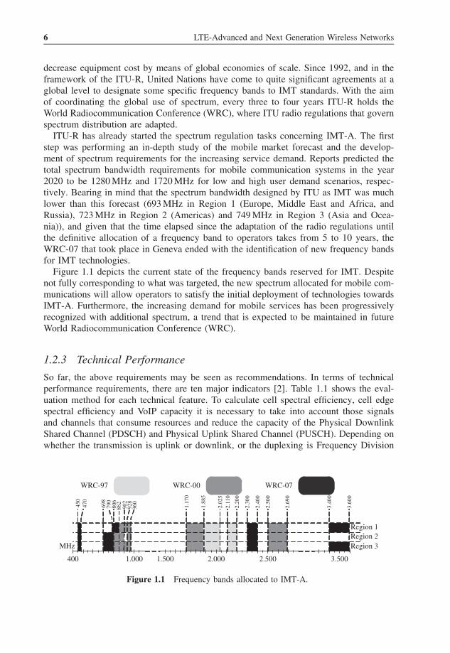
ITU-R has already started the spectrum regulation tasks concerning IMT-A. The firststep was performing an in-depth study of the mobile market forecast and the develop-ment of spectrum requirements for the increasing service demand. Reports predicted thetotal spectrum bandwidth requirements for mobile communication systems in the year2020 to be 1280 MHz and 1720 MHz for low and high user demand scenarios, respec-tively. Bearing in mind that the spectrum bandwidth designed by ITU as IMT was muchlower than this forecast (693 MHz in Region 1 (Europe, Middle East and Africa, andRussia), 723 MHz in Region 2 (Americas) and 749 MHz in Region 3 (Asia and Ocea-nia)), and given that the time elapsed since the adaptation of the radio regulations untilthe definitive allocation of a frequency band to operators takes from 5 to 10 years, theWRC-07 that took place in Geneva ended with the identification of new frequency bandsfor IMT technologies.
Figure 1.1 depicts the current state of the frequency bands reserved for IMT. Despitenot fully corresponding to what was targeted, the new spectrum allocated for mobile com-munications will allow operators to satisfy the initial deployment of technologies towardsIMT-A. Furthermore, the increasing demand for mobile services has been progressivelyrecognized with additional spectrum, a trend that is expected to be maintained in futureWorld Radiocommunication Conference (WRC).
1.2.3 Technical Performance
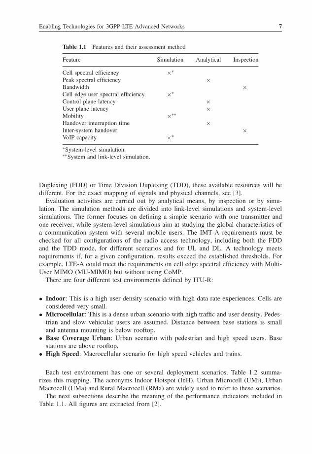
So far, the above requirements may be seen as recommendations. In terms of technicalperformance requirements, there are ten major indicators [2]. Table 1.1 shows the eval-uation method for each technical feature. To calculate cell spectral efficiency, cell edgespectral efficiency and VoIP capacity it is necessary to take into account those signalsand channels that consume resources and reduce the capacity of the Physical DownlinkShared Channel (PDSCH) and Physical Uplink Shared Channel (PUSCH). Depending onwhether the transmission is uplink or downlink, or the duplexing is Frequency Division
WRC-97 WRC-00 WRC-07
MHz
Region 1Region 2Region 3
400 1.000 1.500 2.000 2.500 3.500
450
470
698
790
806
862
902
928
960
1.17
0
1.88
5
2.02
52.
110
2.20
0
2.30
0
2.40
0
2.50
0
2.69
0
3.40
0
3.60
0
Figure 1.1 Frequency bands allocated to IMT-A.
Enabling Technologies for 3GPP LTE-Advanced Networks 7
Table 1.1 Features and their assessment method
Feature Simulation Analytical Inspection
Cell spectral efficiency ×∗Peak spectral efficiency ×Bandwidth ×Cell edge user spectral efficiency ×∗Control plane latency ×User plane latency ×Mobility ×∗∗Handover interruption time ×Inter-system handover ×VoIP capacity ×∗
∗System-level simulation.∗∗System and link-level simulation.
Duplexing (FDD) or Time Division Duplexing (TDD), these available resources will bedifferent. For the exact mapping of signals and physical channels, see [3].
Evaluation activities are carried out by analytical means, by inspection or by simu-lation. The simulation methods are divided into link-level simulations and system-levelsimulations. The former focuses on defining a simple scenario with one transmitter andone receiver, while system-level simulations aim at studying the global characteristics ofa communication system with several mobile users. The IMT-A requirements must bechecked for all configurations of the radio access technology, including both the FDDand the TDD mode, for different scenarios and for UL and DL. A technology meetsrequirements if, for a given configuration, results exceed the established thresholds. Forexample, LTE-A could meet the requirements on cell edge spectral efficiency with Multi-User MIMO (MU-MIMO) but without using CoMP.
There are four different test environments defined by ITU-R:
• Indoor: This is a high user density scenario with high data rate experiences. Cells areconsidered very small.
• Microcellular: This is a dense urban scenario with high traffic and user density. Pedes-trian and slow vehicular users are assumed. Distance between base stations is smalland antenna mounting is below rooftop.
• Base Coverage Urban: Urban scenario with pedestrian and high speed users. Basestations are above rooftop.
• High Speed: Macrocellular scenario for high speed vehicles and trains.
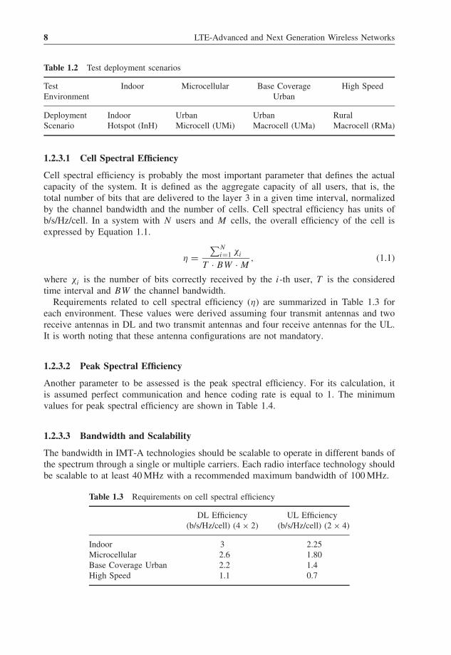
Each test environment has one or several deployment scenarios. Table 1.2 summa-rizes this mapping. The acronyms Indoor Hotspot (InH), Urban Microcell (UMi), UrbanMacrocell (UMa) and Rural Macrocell (RMa) are widely used to refer to these scenarios.
The next subsections describe the meaning of the performance indicators included inTable 1.1. All figures are extracted from [2].
8 LTE-Advanced and Next Generation Wireless Networks
Table 1.2 Test deployment scenarios
Test Indoor Microcellular Base Coverage High SpeedEnvironment Urban
Deployment Indoor Urban Urban RuralScenario Hotspot (InH) Microcell (UMi) Macrocell (UMa) Macrocell (RMa)
1.2.3.1 Cell Spectral Efficiency
Cell spectral efficiency is probably the most important parameter that defines the actualcapacity of the system. It is defined as the aggregate capacity of all users, that is, thetotal number of bits that are delivered to the layer 3 in a given time interval, normalizedby the channel bandwidth and the number of cells. Cell spectral efficiency has units ofb/s/Hz/cell. In a system with N users and M cells, the overall efficiency of the cell isexpressed by Equation 1.1.
η =∑N
i=1 χi
T · BW · M, (1.1)
where χi is the number of bits correctly received by the i-th user, T is the consideredtime interval and BW the channel bandwidth.
Requirements related to cell spectral efficiency (η) are summarized in Table 1.3 foreach environment. These values were derived assuming four transmit antennas and tworeceive antennas in DL and two transmit antennas and four receive antennas for the UL.It is worth noting that these antenna configurations are not mandatory.
1.2.3.2 Peak Spectral Efficiency
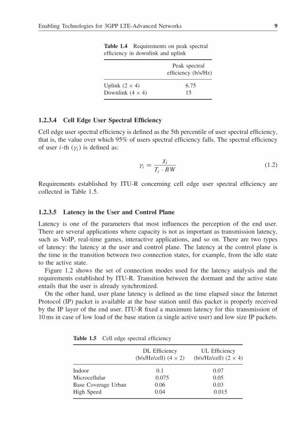
Another parameter to be assessed is the peak spectral efficiency. For its calculation, itis assumed perfect communication and hence coding rate is equal to 1. The minimumvalues for peak spectral efficiency are shown in Table 1.4.
1.2.3.3 Bandwidth and Scalability
The bandwidth in IMT-A technologies should be scalable to operate in different bands ofthe spectrum through a single or multiple carriers. Each radio interface technology shouldbe scalable to at least 40 MHz with a recommended maximum bandwidth of 100 MHz.
Table 1.3 Requirements on cell spectral efficiency
DL Efficiency UL Efficiency(b/s/Hz/cell) (4 × 2) (b/s/Hz/cell) (2 × 4)
Indoor 3 2.25Microcellular 2.6 1.80Base Coverage Urban 2.2 1.4High Speed 1.1 0.7
Enabling Technologies for 3GPP LTE-Advanced Networks 9
Table 1.4 Requirements on peak spectralefficiency in downlink and uplink
Peak spectralefficiency (b/s/Hz)
Uplink (2 × 4) 6.75Downlink (4 × 4) 15
1.2.3.4 Cell Edge User Spectral Efficiency
Cell edge user spectral efficiency is defined as the 5th percentile of user spectral efficiency,that is, the value over which 95% of users spectral efficiency falls. The spectral efficiencyof user i-th (γi) is defined as:
γi = χi
Ti · BW(1.2)
Requirements established by ITU-R concerning cell edge user spectral efficiency arecollected in Table 1.5.
1.2.3.5 Latency in the User and Control Plane
Latency is one of the parameters that most influences the perception of the end user.There are several applications where capacity is not as important as transmission latency,such as VoIP, real-time games, interactive applications, and so on. There are two typesof latency: the latency at the user and control plane. The latency at the control plane isthe time in the transition between two connection states, for example, from the idle stateto the active state.
Figure 1.2 shows the set of connection modes used for the latency analysis and therequirements established by ITU-R. Transition between the dormant and the active stateentails that the user is already synchronized.
On the other hand, user plane latency is defined as the time elapsed since the InternetProtocol (IP) packet is available at the base station until this packet is properly receivedby the IP layer of the end user. ITU-R fixed a maximum latency for this transmission of10 ms in case of low load of the base station (a single active user) and low size IP packets.
Table 1.5 Cell edge spectral efficiency
DL Efficiency UL Efficiency(b/s/Hz/cell) (4 × 2) (b/s/Hz/cell) (2 × 4)
Indoor 0.1 0.07Microcellular 0.075 0.05Base Coverage Urban 0.06 0.03High Speed 0.04 0.015

10 LTE-Advanced and Next Generation Wireless Networks
Less than 10 ms
Less than 100 ms
Active Dormant
Idle
Figure 1.2 Latency in the control plane.
1.2.3.6 Mobility
The proper management of mobility is another feature that ITU-R defined as critical forIMT-A systems. The requirements summarized in Table 1.6 are evaluated for differentscenarios and user velocity, both for DL and UL. Spectral efficiency values are assumedfor a 4 × 2 configuration in DL and 2 × 4 in UL.
1.2.3.7 Handover
Handover time is the time during which the user terminal cannot exchange packets withany base station since it is in the transfer phase from one cell to another. The requirementscan be divided into two cases, as shown in Table 1.7: if base stations are transmittingon the same frequency carrier or on different carriers, either in the same band or indifferent bands.
The handovers described so far are all within the same technology. However, it couldbe the case that the terminal had to move to another technology. IMT-A systems shouldbe able to ensure that such handovers are also supported.
Table 1.6 Spectral efficiency to assess mobility
Velocity Efficiency(km/h) (b/s/Hz/cell)
Indoor 10 1.0Microcellular 30 0.75Base Coverage Urban 120 0.55High Speed 350 0.25
Enabling Technologies for 3GPP LTE-Advanced Networks 11
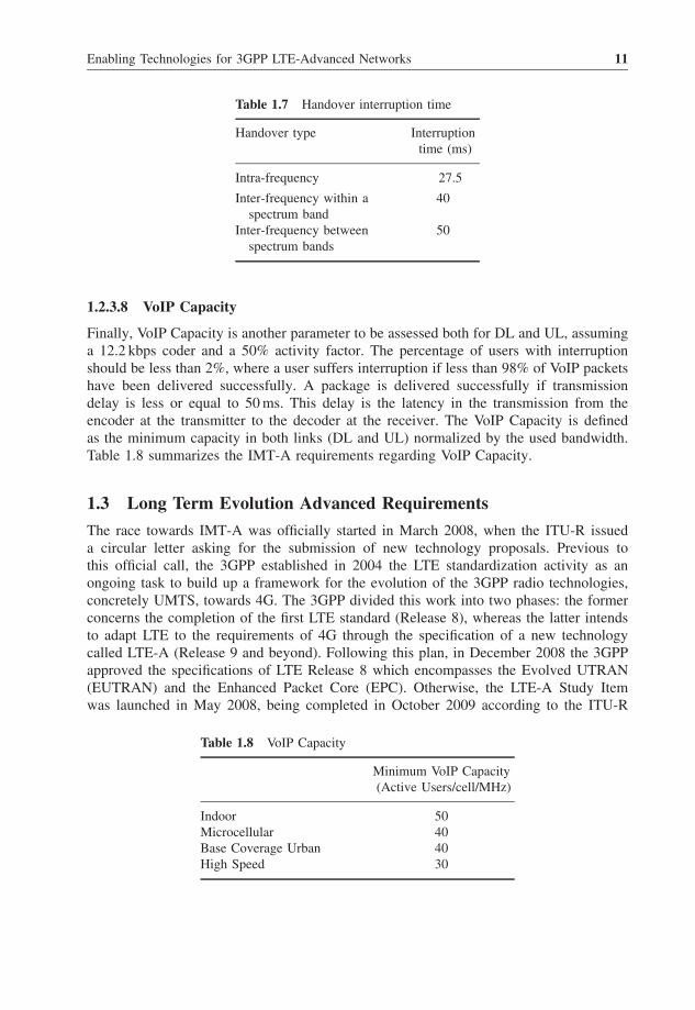
Table 1.7 Handover interruption time
Handover type Interruptiontime (ms)
Intra-frequency 27.5
Inter-frequency within aspectrum band
40
Inter-frequency betweenspectrum bands
50
1.2.3.8 VoIP Capacity
Finally, VoIP Capacity is another parameter to be assessed both for DL and UL, assuminga 12.2 kbps coder and a 50% activity factor. The percentage of users with interruptionshould be less than 2%, where a user suffers interruption if less than 98% of VoIP packetshave been delivered successfully. A package is delivered successfully if transmissiondelay is less or equal to 50 ms. This delay is the latency in the transmission from theencoder at the transmitter to the decoder at the receiver. The VoIP Capacity is definedas the minimum capacity in both links (DL and UL) normalized by the used bandwidth.Table 1.8 summarizes the IMT-A requirements regarding VoIP Capacity.
1.3 Long Term Evolution Advanced Requirements
The race towards IMT-A was officially started in March 2008, when the ITU-R issueda circular letter asking for the submission of new technology proposals. Previous tothis official call, the 3GPP established in 2004 the LTE standardization activity as anongoing task to build up a framework for the evolution of the 3GPP radio technologies,concretely UMTS, towards 4G. The 3GPP divided this work into two phases: the formerconcerns the completion of the first LTE standard (Release 8), whereas the latter intendsto adapt LTE to the requirements of 4G through the specification of a new technologycalled LTE-A (Release 9 and beyond). Following this plan, in December 2008 the 3GPPapproved the specifications of LTE Release 8 which encompasses the Evolved UTRAN(EUTRAN) and the Enhanced Packet Core (EPC). Otherwise, the LTE-A Study Itemwas launched in May 2008, being completed in October 2009 according to the ITU-R
Table 1.8 VoIP Capacity
Minimum VoIP Capacity(Active Users/cell/MHz)
Indoor 50Microcellular 40Base Coverage Urban 40High Speed 30
12 LTE-Advanced and Next Generation Wireless Networks
2007 2008 2009 2010 2011
Circular LetterAssessmentof LTE-ACandidate
Proposal
Assessment
Consensus
Specification
LTE Study Item LTE-A Work Item
LTE Work Item
LTE Release 8 LTE-A Release 9LTE-Acandidate
submission
ITU
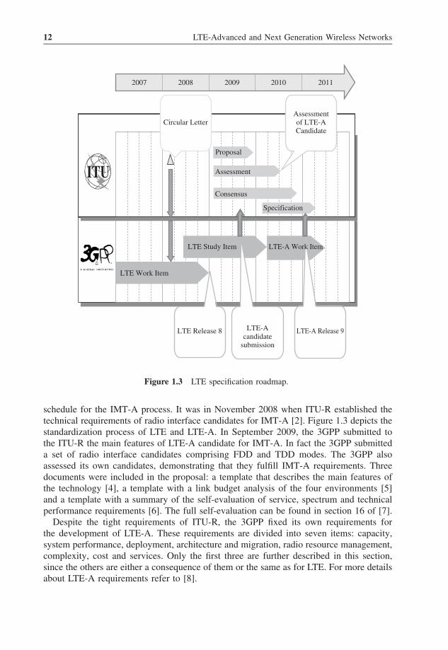
Figure 1.3 LTE specification roadmap.
schedule for the IMT-A process. It was in November 2008 when ITU-R established thetechnical requirements of radio interface candidates for IMT-A [2]. Figure 1.3 depicts thestandardization process of LTE and LTE-A. In September 2009, the 3GPP submitted tothe ITU-R the main features of LTE-A candidate for IMT-A. In fact the 3GPP submitteda set of radio interface candidates comprising FDD and TDD modes. The 3GPP alsoassessed its own candidates, demonstrating that they fulfill IMT-A requirements. Threedocuments were included in the proposal: a template that describes the main features ofthe technology [4], a template with a link budget analysis of the four environments [5]and a template with a summary of the self-evaluation of service, spectrum and technicalperformance requirements [6]. The full self-evaluation can be found in section 16 of [7].
Despite the tight requirements of ITU-R, the 3GPP fixed its own requirements forthe development of LTE-A. These requirements are divided into seven items: capacity,system performance, deployment, architecture and migration, radio resource management,complexity, cost and services. Only the first three are further described in this section,since the others are either a consequence of them or the same as for LTE. For more detailsabout LTE-A requirements refer to [8].
Enabling Technologies for 3GPP LTE-Advanced Networks 13
1.3.1 Requirements Related with Capacity
1.3.1.1 Peak Data Rate
The minimum requirements for LTE-A, in terms of capacity, are marked by the ITU-R,that is, 100 Mbps for high mobility users and 1 Gbps for low mobility users. Yet this goalis further specified pursuing data rates of 1 Gbps just for the downlink, being 500 Mbpsfor the uplink.
1.3.1.2 Latency
The expected latency for the control plane in LTE-A must be much smaller than thelatency set for LTE Release 8. This latency takes into account the radio access networkand core network (excluding the latency of the S1 interface, that is, the interface betweenthe radio access network and the core network) with a lightly loaded system. The transitiontime from the Camped state (after the allocation of the IP address) to the Active state,including the establishment time of the user plane, but excluding the delay associated withS1 interface, must be less than 50 ms. Latency from the Inactive to Active state must beless than 10 ms. Finally, the standard establishes that the system must support 300 activeusers in a bandwidth of 5 MHz.
1.3.2 System Performance
1.3.2.1 Peak Spectral Efficiency
As discussed in Section 1.2.3, the peak spectral efficiency is the highest data rate nor-malized by the bandwidth, considering that the communication is free of errors. With amulti-antenna maximum configuration of up to 8 × 8, the peak spectral efficiency is 30b/s/Hz in the downlink, while in the uplink the peak spectral efficiency is 15 b/s/Hz fora maximum configuration of up to 4 × 4.
1.3.2.2 Mean Spectral Efficiency
Another parameter even more important than peak spectral efficiency, and perhaps morerealistic, is the mean spectral efficiency, defined as the sum of users data rates normalizedby the bandwidth and the number of cells. In the current definition of LTE-A requirements,the spectral efficiency is calculated using a channel model that is different from theone defined by the ITU-R. The description of this channel model can be found in [9]and is the same as the channel used for the evaluation of LTE. Four different caseswere defined including main parameters such as carrier frequency, inter-site distance,bandwidth, penetration losses and speed. Case 1 is used to verify the requirements, whichcorresponds to the urban macrocellular channel of ITU-R. This channel was used tocompare LTE-A to LTE. The results shown in Table 1.9 are a compilation of resultsof the technical report for LTE Release 8 [8, 10] for LTE-A and [2] for IMT-A. If aresource manager only provides resources to the user with best channel, then that userwould enjoy a high spectral efficiency, but others would be penalized thus having a poorspectral efficiency. Therefore, the mean spectral efficiency does not show the reality that
14 LTE-Advanced and Next Generation Wireless Networks
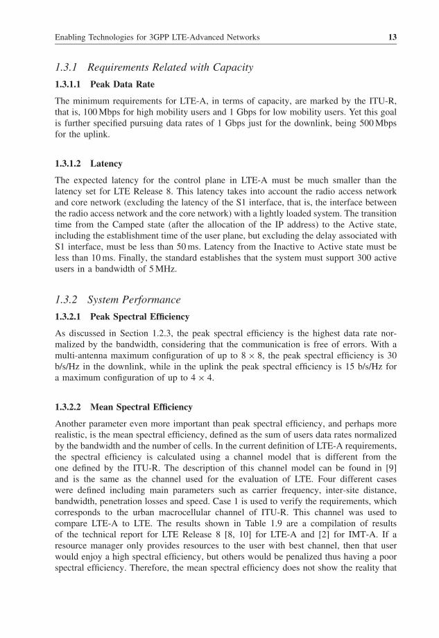
Table 1.9 Mean spectral efficiency requirements
Antenna Conf. LTE Rel 8 (LTE-A) (IMT-A)
Capacity DL 2 × 2 1.69 2.4 -(b/s/Hz/cell) 4 × 2 1.87 2.6 2.2
4 × 4 2.67 3.7 -UL 1 × 2 0.74 1.2 -
2 × 4 - 2.0 1.4
is occurring, as it omits a fair resource allocation. It is in this case when the cell-edge userspectral efficiency metric seems the most appropriate as it ensures that 95% of users areabove a certain value of efficiency. Obviously, in a real situation the resource manageroffers resources more equitably, reaching an equilibrium.
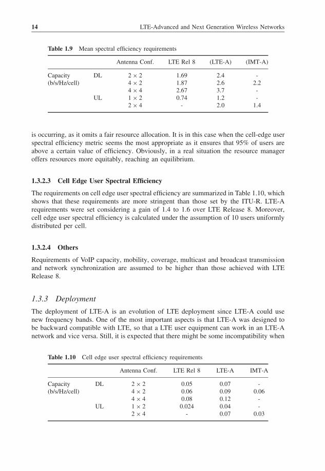
1.3.2.3 Cell Edge User Spectral Efficiency
The requirements on cell edge user spectral efficiency are summarized in Table 1.10, whichshows that these requirements are more stringent than those set by the ITU-R. LTE-Arequirements were set considering a gain of 1.4 to 1.6 over LTE Release 8. Moreover,cell edge user spectral efficiency is calculated under the assumption of 10 users uniformlydistributed per cell.
1.3.2.4 Others
Requirements of VoIP capacity, mobility, coverage, multicast and broadcast transmissionand network synchronization are assumed to be higher than those achieved with LTERelease 8.
1.3.3 Deployment
The deployment of LTE-A is an evolution of LTE deployment since LTE-A could usenew frequency bands. One of the most important aspects is that LTE-A was designed tobe backward compatible with LTE, so that a LTE user equipment can work in an LTE-Anetwork and vice versa. Still, it is expected that there might be some incompatibility when
Table 1.10 Cell edge user spectral efficiency requirements
Antenna Conf. LTE Rel 8 LTE-A IMT-A
Capacity DL 2 × 2 0.05 0.07 -(b/s/Hz/cell) 4 × 2 0.06 0.09 0.06
4 × 4 0.08 0.12 -UL 1 × 2 0.024 0.04 -
2 × 4 - 0.07 0.03
Enabling Technologies for 3GPP LTE-Advanced Networks 15
deploying the network. Another aspect that is being emphasized is the development offemtocellular services, such as remote access of home security, which implies the needof a better indoor deployment of LTE-A.
As discussed in Section 1.2.2, new frequency bands have been reserved for IMT-A. In LTE-A, spectrum can be aggregated up to 100 MHz, either in a contiguous ornoncontiguous manner. Moreover, LTE-A and LTE Release 8 must be able to coexist inthe same spectrum band.
1.4 Long Term Evolution Advanced Enabling Technologies
To meet the demanding requirements of LTE-A, the 3GPP is in the process of develop-ment of certain technological proposals. To this end, 3GPP has focused its attention ondifferent points that required technological innovations: support of wider bandwidth (car-rier aggregation), advanced MIMO techniques, relaying, enhancements for HeNB, andso on. Another relevant feature of LTE-A is that latency requirements are more strictthan ITU-R ones. The proposed changes to improve LTE-A performance indicators arediscussed in the following subsections.
1.4.1 Carrier Aggregation
Carrier aggregation is one of the most important technologies to ensure the success of4G technologies. This concept involves transmitting data in multiple contiguous or non-contiguous Component Carriers (CCs). Each Component Carrier (CC) takes a maximumbandwidth of 20 MHz to be compatible with LTE Release 8. The maximum number ofResource Blocks (RBs) in a CC is 110 and the bandwidth will be assigned followingthe same structure as in LTE, that is, 1.4 MHz (6 RB), 3 MHz (15 RB), 5 MHz (25 RB),10 MHz (50 RB), 15 MHz (75 RB) and 20 MHz (100 RB). However, it is possible thatthere are certain CCs that are not compatible with LTE.
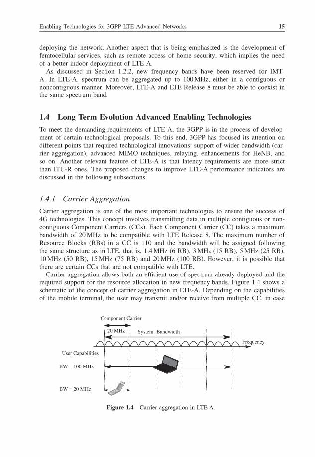
Carrier aggregation allows both an efficient use of spectrum already deployed and therequired support for the resource allocation in new frequency bands. Figure 1.4 shows aschematic of the concept of carrier aggregation in LTE-A. Depending on the capabilitiesof the mobile terminal, the user may transmit and/or receive from multiple CC, in case
Component Carrier
User Capabilities
BW = 100 MHz
BW = 20 MHz
20 MHz System Bandwidth
Frequency
Figure 1.4 Carrier aggregation in LTE-A.
16 LTE-Advanced and Next Generation Wireless Networks
of an LTE-A terminal with a maximum bandwidth of 100 MHz. Meanwhile, an LTERelease 8 equipment may only transmit and/or receive in a single CC, with a maximumbandwidth of 20 MHz. Given the possible bandwidth configurations, the transmitter shouldsupport, depending on the capabilities of the mobile terminal, three possible scenarios:aggregation of several contiguous CCs within the same band, aggregation of several non-contiguous CCs within the same band and aggregation of several non-contiguous CCslocated in different bands. In [11] various deployment scenarios were considered to meetthe requirements of ITU-R. Among them, four scenarios are the most significant, beingsummarized in Table 1.11 for the FDD and TDD modes. As an example, new frequencybands could be added to existing UMTS bands of 1.8 GHz, 2.1 GHz and 2.6 GHz or newbands could be added at 3.5 GHz.
When working on non-contiguous CCs, it is required null interference between carriersand, therefore, guard bands are added. Otherwise, in cases of aggregation of contiguousCC, there is not such a large guard band, which allows a more efficient use of spectrum.However, in order to be compatible with the LTE frequency raster of 100 kHz and, inturn, preserve the orthogonality of the subcarriers with a spacing of 15 kHz, the distancebetween carriers must be a multiple of 300 kHz. This can cause certain subcarriers not tobe used. Still, these could be used as guard bands.
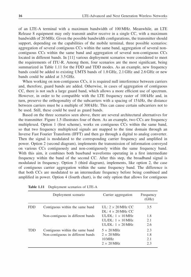
Based on the three scenarios seen above, there are several architectural alternatives forthe transmitter. Figure 1.5 illustrates four of them. As an example, two CCs are frequencymultiplexed. Option 1 (first scheme), works on contiguous CCs within the same band,so that two frequency multiplexed signals are mapped to the time domain through anInverse Fast Fourier Transform (IFFT) and then go through a digital to analog converter.Then the signal is modulated to the corresponding carrier frequency and amplified inpower. Option 2 (second diagram), implements the transmission of information conveyedon various CCs contiguously and non-contiguously within the same frequency band.With this aim, it combines both baseband waveforms operating in a first intermediatefrequency within the band of the second CC. After this step, the broadband signal ismodulated in frequency. Option 3 (third diagram), implements, like option 2, the caseof contiguous carrier aggregation within the same frequency band. The difference isthat both CCs are modulated to an intermediate frequency before being combined andamplified in power. Option 4 (fourth chart), is the only option that allows for contiguous
Table 1.11 Deployment scenarios of LTE-A
Deployment scenario Carrier aggregation Frequency(GHz)
FDD Contiguous within the same band UL: 2 × 20 MHz CC 3.5DL: 4 × 20 MHz CC
Non-contiguous in different bands UL/DL: 1 × 10 MHz 1.8UL/DL: 1 × 10 MHz 2.1UL/DL: 1 × 20 MHz 2.6
TDD Contiguous within the same band 5 × 20 MHz 2.3Non-contiguous in different bands 2 × 20 MHz 1.8
10 MHz 2.12 × 20 MHz 2.3
Enabling Technologies for 3GPP LTE-Advanced Networks 17
Baseband 1
Baseband 1
Baseband 1
Baseband 2
Baseband 1
Baseband 2
IFFT
IFFT
IFFT
IFFT
IFFT
IFFT
IFFT
D/A
D/A
D/A
D/A
D/A
D/A
D/A
RF Amplifier
RF Amplifier
RF Amplifier
RF Amplifier
RF Amplifier
RF Filter
RF Filter
RF Filter
RF Filter
RF Filter
RF Filter
Baseband 2
Baseband 2
L1
L1
L1
L1
L2
L2
L2
Figure 1.5 Possible architectures for the transmitter in three aggregation scenarios. In order, fromtop to bottom, are options from 1 to 4.
18 LTE-Advanced and Next Generation Wireless Networks
and non-contiguous aggregation within the same band or in different frequency bands.This scheme employs multiple radio frequency chains and multiple power amplifiers. Thecombination, therefore, is performed over amplified signals that are transmitted througha single antenna. The choice of the proper architecture depends on the cost, complexity,bandwidth of the amplifier and if the CCs are contiguous or non-contiguous.
In the uplink, one of the problems caused by carrier aggregation is the loss of efficiencyin the power amplifier. The cubic metric parameter defined in [12] is useful for assessingthe efficiency of power amplifiers. In [13] it is shown that the higher the number of CCsassigned, the higher the cubic metric in case of SC-FDMA. This increase is significantwhen using two CCs, while from 3 CCs this increment occurs more gradually. Still, thecubic metric is smaller than in the case of Orthogonal Frequency Division Multiple Access(OFDMA). The transmission over multiple carriers is usually restricted to users with goodchannel conditions, which will reduce the effect of this loss of efficiency. Moreover,cell-edge users will generally not aggregate carriers, so they will not be affected either.
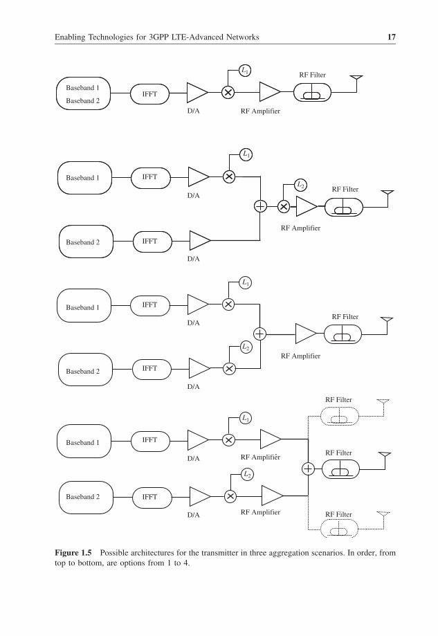
In the physical layer of LTE-A, a single transport block (two in the case of spatialmultiplexing) and a single Hybrid Automatic Repeat reQuest (HARQ) entity will beassociated with a CC. This allows separate link adaptation to improve the transmissionof data from each CC since it will adapt better to the conditions of each CCs. Figure 1.6shows a description of the basic structure of the physical layer and Medium AccessControl (MAC) layer. As shown, LTE-A will support a maximum of five parallel LTERelease 8 processing chains. Of course, the CC may be in different frequency bands.
There are three downlink control channels: the Physical Control Format Indicator Chan-nel (PCFICH), the Physical Downlink Control Channel (PDCCH) and the Physical HybridARQ Indicator Channel (PHICH). The design principle of these channels is, in general,to ensure backward compatibility with LTE Release 8. The signaling control for carrieraggregation is still under study. So far, the following decisions have been taken withrespect to these three channels:
HARQ
L1 L1 L1 L1 L1
HARQ HARQ HARQ HARQ
Figure 1.6 Structure of the MAC and PHY layer of LTE-A.
Enabling Technologies for 3GPP LTE-Advanced Networks 19
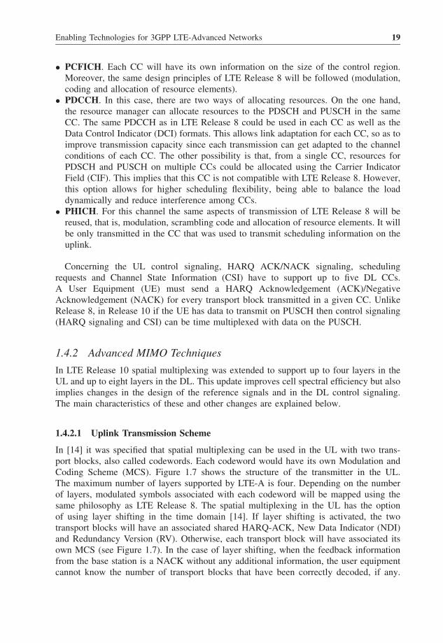
• PCFICH. Each CC will have its own information on the size of the control region.Moreover, the same design principles of LTE Release 8 will be followed (modulation,coding and allocation of resource elements).
• PDCCH. In this case, there are two ways of allocating resources. On the one hand,the resource manager can allocate resources to the PDSCH and PUSCH in the sameCC. The same PDCCH as in LTE Release 8 could be used in each CC as well as theData Control Indicator (DCI) formats. This allows link adaptation for each CC, so as toimprove transmission capacity since each transmission can get adapted to the channelconditions of each CC. The other possibility is that, from a single CC, resources forPDSCH and PUSCH on multiple CCs could be allocated using the Carrier IndicatorField (CIF). This implies that this CC is not compatible with LTE Release 8. However,this option allows for higher scheduling flexibility, being able to balance the loaddynamically and reduce interference among CCs.
• PHICH. For this channel the same aspects of transmission of LTE Release 8 will bereused, that is, modulation, scrambling code and allocation of resource elements. It willbe only transmitted in the CC that was used to transmit scheduling information on theuplink.
Concerning the UL control signaling, HARQ ACK/NACK signaling, schedulingrequests and Channel State Information (CSI) have to support up to five DL CCs.A User Equipment (UE) must send a HARQ Acknowledgement (ACK)/NegativeAcknowledgement (NACK) for every transport block transmitted in a given CC. UnlikeRelease 8, in Release 10 if the UE has data to transmit on PUSCH then control signaling(HARQ signaling and CSI) can be time multiplexed with data on the PUSCH.
1.4.2 Advanced MIMO Techniques
In LTE Release 10 spatial multiplexing was extended to support up to four layers in theUL and up to eight layers in the DL. This update improves cell spectral efficiency but alsoimplies changes in the design of the reference signals and in the DL control signaling.The main characteristics of these and other changes are explained below.
1.4.2.1 Uplink Transmission Scheme
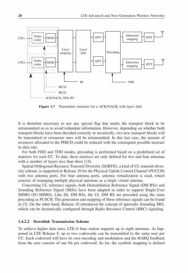
In [14] it was specified that spatial multiplexing can be used in the UL with two trans-port blocks, also called codewords. Each codeword would have its own Modulation andCoding Scheme (MCS). Figure 1.7 shows the structure of the transmitter in the UL.The maximum number of layers supported by LTE-A is four. Depending on the numberof layers, modulated symbols associated with each codeword will be mapped using thesame philosophy as LTE Release 8. The spatial multiplexing in the UL has the optionof using layer shifting in the time domain [14]. If layer shifting is activated, the twotransport blocks will have an associated shared HARQ-ACK, New Data Indicator (NDI)and Redundancy Version (RV). Otherwise, each transport block will have associated itsown MCS (see Figure 1.7). In the case of layer shifting, when the feedback informationfrom the base station is a NACK without any additional information, the user equipmentcannot know the number of transport blocks that have been correctly decoded, if any.
20 LTE-Advanced and Next Generation Wireless Networks
CW1Turbocoder
MOD
Turbocoder
MOD
Layermapping
Layershift
RI
DFT
DFTSubcarriermapping
Subcarriermapping
IFFT
IFFT
PMI
Precoding
MCS2
MCS1
ACK/NACK, NDI, RV
CW2
Figure 1.7 Transmitter structure for a ACK/NACK with layer shift.
It is therefore necessary to use any special flag that marks the transport block to beretransmitted so as to avoid redundant information. However, depending on whether bothtransport blocks have been decoded correctly or incorrectly, two new transport blocks willbe transmitted or erroneous ones will be retransmitted. In this last case, the amount ofresources allocated to the PHICH could be reduced with the consequent possible increasein data rate.
For both FDD and TDD modes, precoding is performed based on a predefined set ofmatrices for each CC. To date, these matrices are only defined for two and four antennaswith a number of layers less than three [14].
Spatial Orthogonal-Resource Transmit Diversity (SORTD), a kind of UL transmit diver-sity scheme, is supported in Release 10 for the Physical Uplink Control Channel (PUCCH)with two antenna ports. For four antenna ports, antenna virtualization is used, whichconsists of managing multiple physical antennas as a single virtual antenna.
Concerning UL reference signals, both Demodulation Reference Signal (DM RSs) andSounding Reference Signal (SRSs) have been adapted in order to support Single-UserMIMO (SU-MIMO). Like DL DM RSs, the UL DM RS are precoded using the sameprecoding as PUSCH. The generation and mapping of these reference signals can be foundin [3]. On the other hand, Release 10 introduced the concept of aperiodic Sounding SRS,which can be dynamically configured through Radio Resource Control (RRC) signaling.
1.4.2.2 Downlink Transmission Scheme
To achieve higher data rates, LTE-A base station supports up to eight antennas. As hap-pened in LTE Release 8, up to two codewords can be transmitted to the same user perCC. Each codeword will have its own encoding and modulation and the HARQ feedbackfrom the user consists of one bit per codeword. So far, the symbols mapping is defined
Enabling Technologies for 3GPP LTE-Advanced Networks 21
Layer 5
CW1 S/P
S/P
S/P
S/P
Precoding Precoding
CW2
CW1
CW2
CW1 S/P
S/P
S/P
S/P
Precoding Precoding
CW2
CW1
CW2
Layer 6
Layer 7 Layer 8
Figure 1.8 Codeword mapping to spatial multiplexing layers.
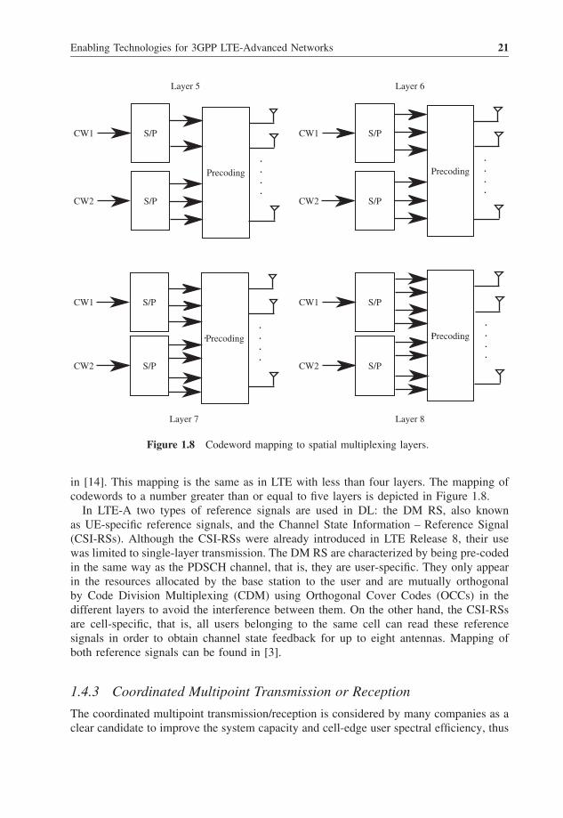
in [14]. This mapping is the same as in LTE with less than four layers. The mapping ofcodewords to a number greater than or equal to five layers is depicted in Figure 1.8.
In LTE-A two types of reference signals are used in DL: the DM RS, also knownas UE-specific reference signals, and the Channel State Information – Reference Signal(CSI-RSs). Although the CSI-RSs were already introduced in LTE Release 8, their usewas limited to single-layer transmission. The DM RS are characterized by being pre-codedin the same way as the PDSCH channel, that is, they are user-specific. They only appearin the resources allocated by the base station to the user and are mutually orthogonalby Code Division Multiplexing (CDM) using Orthogonal Cover Codes (OCCs) in thedifferent layers to avoid the interference between them. On the other hand, the CSI-RSsare cell-specific, that is, all users belonging to the same cell can read these referencesignals in order to obtain channel state feedback for up to eight antennas. Mapping ofboth reference signals can be found in [3].
1.4.3 Coordinated Multipoint Transmission or Reception
The coordinated multipoint transmission/reception is considered by many companies as aclear candidate to improve the system capacity and cell-edge user spectral efficiency, thus
22 LTE-Advanced and Next Generation Wireless Networks
fulfilling the requirements of LTE-A. The current LTE Release 8 allows a certain degreeof cooperation between base stations in order to reduce interference. However, a bigimprovement is expected in this technique with LTE-A as compared with LTE Release 8.
1.4.3.1 Coordinated Transmission
In a CoMP system, multiple cells (likely from different base stations) are cooperatingin the transmission of data to multiple users. We can distinguish two types of CoMPtechniques:
• Joint Processing (JP) techniques. Multiple cells transmit the same information to auser. A cell can consist of a set of antenna elements within the base station or outside,geographically separated. This level of cooperation requires user data to be sharedbetween cooperating cells.
• Coordinated Scheduling and Beamforming (CS/CB) techniques. The information isonly sent from a single cell, but the scheduling and beamforming decisions are madetaking into account other cells status so as to coordinate interferences. This techniquedoes not need to share user data among cells.
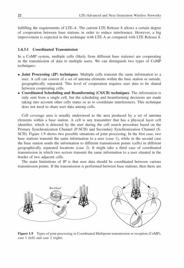
Cell coverage area is usually understood as the area produced by a set of antennaelements within a base station. A cell is any transmitter that has a physical layer cellidentifier, which is detected by the user during the cell search procedure based on thePrimary Synchronization Channel (P-SCH) and Secondary Synchronization Channel (S-SCH). Figure 1.9 shows two possible situations of joint processing. In the first case, twobase stations transmit the same information to a user (case 1), while in the second casethe base station sends the information to different transmission points (cells) in differentgeographically separated locations (case 2). It might take a third case of coordinatedtransmission in which two sectors transmit the same information to a user situated in theborder of two adjacent cells.
The main limitations of JP is that user data should be coordinated between varioustransmission points. If the transmission is performed between base stations, then there are
Backhaul
Figure 1.9 Types of joint processing in Coordinated Multipoint transmission or reception (CoMP),case 1 (left) and case 2 (right).

Enabling Technologies for 3GPP LTE-Advanced Networks 23
limitations with the latency and backhaul capacity. On the other hand, if coordination iscarried out as in case 2, that is, through a distributed antenna system or remote radio headsbelonging to the same base station, communication is assumed to be faster. With regardto CS/CB its main limitations are related to the assumption of certain knowledge of thechannel quality of cooperating cells. These techniques lack backhaul capacity problems,since cells do not exchange user data. However, latency remains a limitation due to theexchange of channel state information. No major changes are expected in the networkarchitecture to implement this CoMP technique and, therefore, it seems to be the mostappropriate technique in scenarios of transmission between base stations.
The LTE-A radio interface must support different feedback mechanisms of cooperatingcells. The user dynamically estimates the channel for each one of the transmission pointsto facilitate the decision on which a set of transmitters will participate in the cooperativetransmission. In the case of TDD mode, channel reciprocity could be assumed.
1.4.3.2 Coordinated Reception
OFDM can eliminate the interference within the cell, since the high data rate is dividedinto parallel flows at lower rates, transmitted over orthogonal subcarriers. However, in amulti-cellular system OFDM cannot remove inter-cell interference. Therefore, coordinatedreception has been proposed to reduce this type of interference (especially for cell-edgeusers), also known as Inter-Cell Interference (I-CI). Coordinated reception is not onlyexpected to minimize interference, but also help improve the average cell efficiency ofthe cell and the cell-edge efficiency.
As explained before, CoMP is a cooperative technology that coordinates multiplegeographically separated cells. The cooperation implies sharing user data, schedulinginformation and channel quality. Clearly, CoMP reception further affects the imple-mentation rather than the specifications. Figure 1.10 shows an overview of coordinatedmulti-point reception. There is a base station that serves all the mobile terminals of thecell. The three mobile terminals transmit their data on the same resources simultaneously.The transmitted signal of each user to the base station corresponds to the interference tothe neighboring cell shown in the figure with a dotted line. Because users whose infor-mation is processed are geographically close together, the interference might be high andthere would be a degradation in performance. This interference could be reduced via jointprocessing. Although in Figure 1.10 it is not showed, a central server is responsible forcontrolling the behavior of the multiple cells involved in the cooperation. However, itcould be physically integrated in any base station.
1.4.4 Relaying
The use of relays was initially envisioned as a tool to increase cell coverage. With theincrease of data traffic, operators thought of a new solution that could improve the datarate in certain areas. However, increasing the number of base stations entails a cost thatoperators cannot afford. This made operators consider the study and development of relaysas a means to improve coverage in hotspots, mobility in public transportation vehicles(trains, buses, etc.) and improvement in transmission capacity on the cell edge.
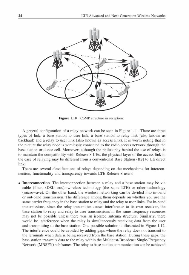
24 LTE-Advanced and Next Generation Wireless Networks
Figure 1.10 CoMP structure in reception.
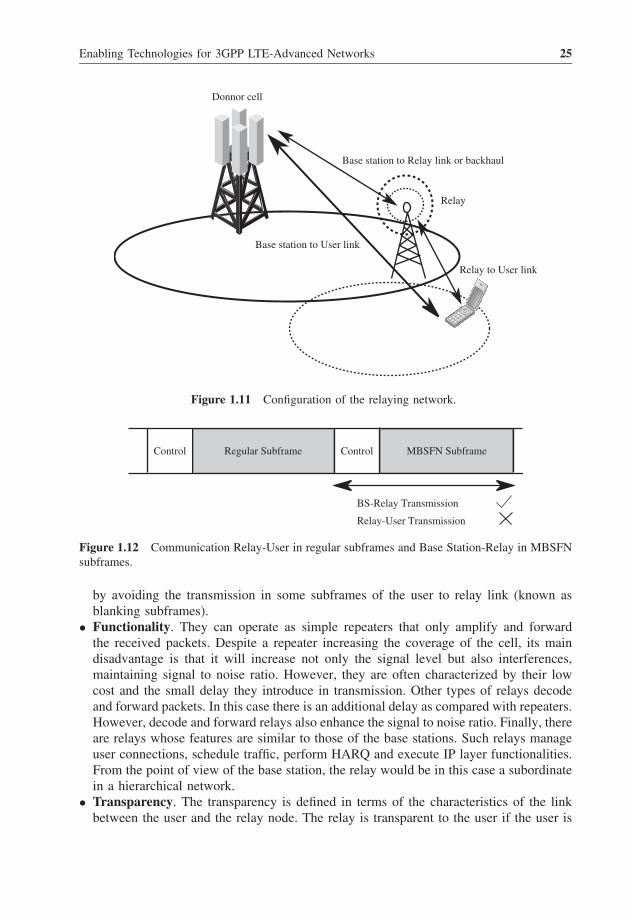
A general configuration of a relay network can be seen in Figure 1.11. There are threetypes of link: a base station to user link, a base station to relay link (also known asbackhaul) and a relay to user link (also known as access link). It is worth noting that inthe picture the relay node is wirelessly connected to the radio access network through thebase station or donor cell. Moreover, although the philosophy behind the use of relays isto maintain the compatibility with Release 8 UEs, the physical layer of the access link inthe case of relaying may be different from a conventional Base Station (BS) to UE directlink.
There are several classifications of relays depending on the mechanisms for intercon-nection, functionality and transparency towards LTE Release 8 users:
• Interconnection. The interconnection between a relay and a base station may be viacable (fiber, xDSL, etc.), wireless technology (the same LTE) or other technology(microwave). On the other hand, the wireless networking can be divided into in-bandor out-band transmission. The difference among them depends on whether you use thesame carrier frequency in the base station to relay and the relay to user links. For in-bandtransmissions, since the relay transmitter causes interference to its own receiver, thebase station to relay and relay to user transmissions in the same frequency resourcesmay not be possible unless there was an isolated antenna structure. Similarly, therewould be interference when the relay is simultaneously receiving data from the userand transmitting to the base station. One possible solution is illustrated in Figure 1.12.The interference could be avoided by adding gaps where the relay does not transmit tothe terminals when data is being received from the base station. During these gaps, thebase station transmits data to the relay within the Multicast-Broadcast Single-FrequencyNetwork (MBSFN) subframes. The relay to base station communication can be achieved
Enabling Technologies for 3GPP LTE-Advanced Networks 25
Donnor cell
Base station to Relay link or backhaul
Relay
Base station to User link
Relay to User link
Figure 1.11 Configuration of the relaying network.
Control Control MBSFN Subframe
BS-Relay Transmission
Relay-User Transmission
Regular Subframe
Figure 1.12 Communication Relay-User in regular subframes and Base Station-Relay in MBSFNsubframes.
by avoiding the transmission in some subframes of the user to relay link (known asblanking subframes).
• Functionality. They can operate as simple repeaters that only amplify and forwardthe received packets. Despite a repeater increasing the coverage of the cell, its maindisadvantage is that it will increase not only the signal level but also interferences,maintaining signal to noise ratio. However, they are often characterized by their lowcost and the small delay they introduce in transmission. Other types of relays decodeand forward packets. In this case there is an additional delay as compared with repeaters.However, decode and forward relays also enhance the signal to noise ratio. Finally, thereare relays whose features are similar to those of the base stations. Such relays manageuser connections, schedule traffic, perform HARQ and execute IP layer functionalities.From the point of view of the base station, the relay would be in this case a subordinatein a hierarchical network.
• Transparency. The transparency is defined in terms of the characteristics of the linkbetween the user and the relay node. The relay is transparent to the user if the user is
26 LTE-Advanced and Next Generation Wireless Networks
not aware of being served by an entity other than a classical base station, that is, therelay. Conversely, if the user is aware of being connected to another entity, relayingwould be non-transparent.
Another possible classification differentiates if the relay depends on a donor cell or not.In the former case, the relay has not got a cell identifier but could have a relay identifier.Some of the resource management functions would take place in the base station of thedonor cell and the remaining in the relay node. In the latter case, the cells created by therelay would have a unique cell identifier. From the point of view of the user, the accessto a relay node would be identical to the access to a base station. In either case, the relaymust support LTE Release 8 user equipments.
Based on the above classifications, 3GPP defined two types of relays:
• Type 1. The Type 1 relay is perceived by the user as a new LTE base station, providingsupport to Release 8 terminals. The cells served by the relay have their own cellidentifier. Therefore, a relay type 1 is not transparent to the user that will measure thesignal level received from the base station and the relay getting connected to the bestserver. The relay transmits its own synchronization and reference signals. Similarly,the user feeds back information about channel quality and HARQ processes to therelay. This type of relay node increases coverage. However, it implements the samefunctionalities as a conventional base station and, therefore, its cost could be similar.Moreover, type 1 relays can be divided into type 1a and 1b, which have the samecharacteristics as type 1 relays but the first operates out-band, while the second operatesin-band but with isolated antennas.
• Type 2. The Type 2 relay is an in-band node that uses the same cell identifier as thedonor cell, allowing the user to move between the base station and the relay nodewithout handovers. Therefore, the type 2 relay would be able to serve users in atransparent manner without requiring the handover when the user moves outside thebase station coverage. The CSI-RSs are not sent and, therefore, user equipments donot measure the quality of the relay to user link. A significant cost saving is made byusing this type of relay nodes.
As mentioned above, in order to allow for an in-band transmission in the base stationto relay link, a time division multiplexing is required. The gap during which the BStransmits data to the relay is less than the subframe duration. To manage this new situation,new physical channels have been defined: R-PDCCH, R-PDSCH and R-PUSCH. TheR-PDCCH physical channel is used to allocate resources to the R-PDSCH or R-PUSCHin the backhaul in a dynamic or semi-persistent way. Resource blocks allocated to theR-PDCCH may not be fully utilized. In that case, these free resources could be used bythe PDSCH or the R-PDSCH. The processing chain of the R-PDCCH should reuse theRelease 8 functionality, but with the possibility of eliminating unnecessary procedures.
1.4.5 Enhancements for Home eNodeBs
Mobile subscribers are increasingly demanding ubiquity connection and higher data rates.3G Home NodeBs were introduced in the UMTS Terrestrial Radio Access Network
Enabling Technologies for 3GPP LTE-Advanced Networks 27
HeNB
S1-MMe
C-Plane
U-Plane
HeNB GW
S1-U
S1-U
S1-MME
MME
S GW
Evolved Packet Core
HeNB
SecurityGW
X2
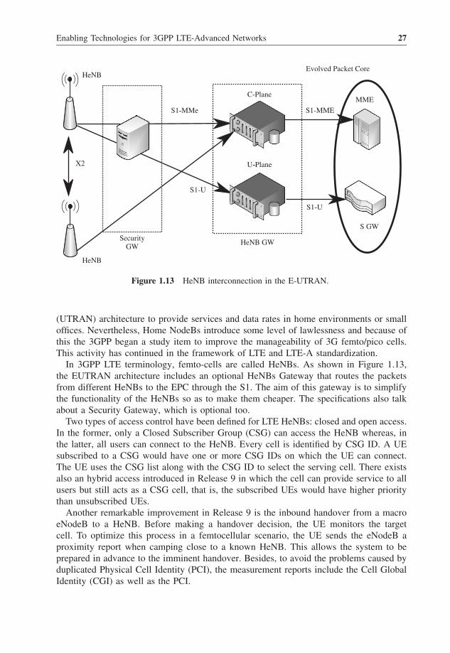
Figure 1.13 HeNB interconnection in the E-UTRAN.
(UTRAN) architecture to provide services and data rates in home environments or smalloffices. Nevertheless, Home NodeBs introduce some level of lawlessness and because ofthis the 3GPP began a study item to improve the manageability of 3G femto/pico cells.This activity has continued in the framework of LTE and LTE-A standardization.
In 3GPP LTE terminology, femto-cells are called HeNBs. As shown in Figure 1.13,the EUTRAN architecture includes an optional HeNBs Gateway that routes the packetsfrom different HeNBs to the EPC through the S1. The aim of this gateway is to simplifythe functionality of the HeNBs so as to make them cheaper. The specifications also talkabout a Security Gateway, which is optional too.
Two types of access control have been defined for LTE HeNBs: closed and open access.In the former, only a Closed Subscriber Group (CSG) can access the HeNB whereas, inthe latter, all users can connect to the HeNB. Every cell is identified by CSG ID. A UEsubscribed to a CSG would have one or more CSG IDs on which the UE can connect.The UE uses the CSG list along with the CSG ID to select the serving cell. There existsalso an hybrid access introduced in Release 9 in which the cell can provide service to allusers but still acts as a CSG cell, that is, the subscribed UEs would have higher prioritythan unsubscribed UEs.
Another remarkable improvement in Release 9 is the inbound handover from a macroeNodeB to a HeNB. Before making a handover decision, the UE monitors the targetcell. To optimize this process in a femtocellular scenario, the UE sends the eNodeB aproximity report when camping close to a known HeNB. This allows the system to beprepared in advance to the imminent handover. Besides, to avoid the problems caused byduplicated Physical Cell Identity (PCI), the measurement reports include the Cell GlobalIdentity (CGI) as well as the PCI.

28 LTE-Advanced and Next Generation Wireless Networks
3GPP specifications also allow limiting IP access for HeNB users to a local network,what is referred to as Local IP Access (LIPA). Release 10 extends this concept to limit theaccess to a corporate network. Moreover, HeNBs must support Selected IP Traffic Offload(SIPTO), which allows internet traffic to flow from the femtocell directly to the internet,bypassing the EPC. Both mechanisms can be enabled/disabled by the mobile operator.
1.4.6 Machine-Type Communications
Machine-to-Machine (M2M) communications, also called Machine-Type Communications(MTC), refer to the type of communication between entities that does not need any humaninteraction. Some examples of MTC are domotic applications that manage heating andair conditioning systems, alarms, sensors and valves.
There is no consensus about the general network architecture of MTC. 3GPP considersthree different scenarios for MTC depicted in Figure 1.14:
• Scenario A. The MTC application directly interacts with the UE (MTC device).• Scenario B. The MTC application interacts with the MTC server that is located outside
the operator domain.• Scenario C. The MTC application interacts with the MTC server that is located inside
the operator domain.
In all cases, the 3GPP radio access network provides transport and communicationservices, including 3GPP bearer services, IP Multimedia Subsystem (IMS) and ShortMessage Service (SMS). From Release 10 on, the 3GPP is addressing some specificproblems of MTC:
(a) (b) (c)
MTCApplication
MTCApplication
MTCApplication
MTCserver
MTCserver3GPP
boundary3GPP
boundary3GPP
boundary
3GPPNetwork
3GPPNetwork
3GPPNetwork
UE UE
Direct Model
Indirect Model
UE
Figure 1.14 MTC scenarios.
Enabling Technologies for 3GPP LTE-Advanced Networks 29
• Signaling congestion and overloading of the core network. A large number of MTCdevices are deployed in a specific area. This can cause, among other things, intolerabledelays, packet losses or the service failure. To reduce this problem, load control mech-anisms based on different priorities between MTC devices can be implemented. In asimilar way, Extended Access Barring (EAB) methods consist of restricting the accessto specific UEs. Besides, separate Random Access Channel (RACH) resources couldbe allocated to M2M.
• Small data transmission. MTC does not require high peak data rates, advanced MIMOtecniques, HARQ or sophisticated channel estimations.
• MTC addressing. With so many devices, IP addressing can be a problem. As a solution,similar devices can be grouped sharing a common identifier.
1.4.7 Self-Optimizing Networks (SON)
It is apparent that networks are becoming larger in scales and more complex in design.They have grown beyond the limit of manual administration. At the same time, reductionof cost is one of the goals of 4G systems, affecting them anywhere from the cost pertransmitted bit until the CAPital EXpenditure (CAPEX) and OPerational EXpenditure(OPEX) reduction. There is a rising pressure from network operators to make networksand systems more manageable, their operations more efficient, and their deployment andmaintenance more cost effective.
In the early deployment of 2G networks Operations and Maintenance (OAM) was basedon in site operation. Nowadays, with 3G systems, OAM relies on software applications thatmanage the wireless system in a centralized way. However, the expected complexity ofnext generation wireless systems is increasing the research community interest towards thedesign of 4G systems infrastructures by exploiting “cognitive networking” capabilities.Wireless networks cannot remain primitive and the management systems omnipotent.Conversely, a large degree of self-awareness and self-governess must be considered inthe new concept of networks and systems. In response, there has been a major pushfor self-managing networks and systems in the last five years. Although managementautomaton has been taken into account for decades, never before there has been such astrong concern from both academia and industry, and the need for effective solutions isimmediate.
Self-Organizing Network (SON) allows the network to detect changes, make intelligentdecisions based upon these inputs, and then implement the appropriate action. The sys-tems must be location and situation-aware, and must take advantage of this information todynamically configure themselves in a distributed fashion. Applied to resource manage-ment, SON allows, for example, making a dynamic and optimum management of radioresources at the border of cells in such a way that there exists an automatic coordinationof the radio resource utilization at the cell-edge in order to avoid performance loss oreven degradation of service.
In LTE Release 8, SON concepts were associated with initial equipment installation,also known as eNodeB self-configuration. Main procedures included:
• Automatic Inventory.• Automatic Software Download.
30 LTE-Advanced and Next Generation Wireless Networks
• Automatic Neighbor Relation.• Automatic PCI Assignment.
The next release of SON (Release 9) provided some procedures covering networkoptimization. More specifically, the Release 9 standard included these additional use cases:
• Mobility Robustness/Handover Optimization.• RACH Optimization.• Load Balancing Optimization.• Inter-Cell Interference Coordination.
The latest release of SON that appeared in Release 10 provided additional functionalitiesand methods to manage heterogeneous networks:
• Coverage and Capacity Optimization.• Enhanced Inter-Cell Interference Coordination.• Cell Outage Detection and Compensation.• Self-healing Functions.• Minimization of Drive Testing.• Energy Savings.
All SON functionalities are mostly described in [15].
1.4.7.1 Inter-Cell Interference Coordination in LTE
In the downlink, a bitmap known as Relative Narrowband Transmit Power (RNTP) indi-cator can be exchanged among eNodeBs through the X2 interface. This ON-OFF indicatorinforms the neighbor cells if the eNodeB intends to transmit on a certain RB over a certainpower threshold or not. One bit per RB in the frequency domain is sent. The exact valueof the upper limit and the periodicity in the reporting are configurable.
The use of the RNTP indicator allows eNodeBs to choose the proper RBs when schedul-ing users according to the interference level introduced by their neighbors. The decisionmaking process followed by eNodeBs after receiving RNTP indicators is not standardized,which fosters competence among different implementations.
In the uplink, two messages are exchanged: the Interference Overload Indication (IOI),which indicates the interference level on all RBs, and the High Interference Indication(HII), which informs about the future plans for the uplink transmission. The receiving cellsshould take this information into account by not scheduling cell-edge users in these RBs.
1.4.8 Improvements to Latency in the Control and User Plane
Although LTE Release 8 technology already meets the requirements of ITU-R in terms oflatency (100 ms from camped to connected state and 10 ms from dormant to active state),several mechanisms could be used to reduce latency (about 50 ms from camped to con-nected state). Improvements related to the transition from camped to connected state are:
Enabling Technologies for 3GPP LTE-Advanced Networks 31
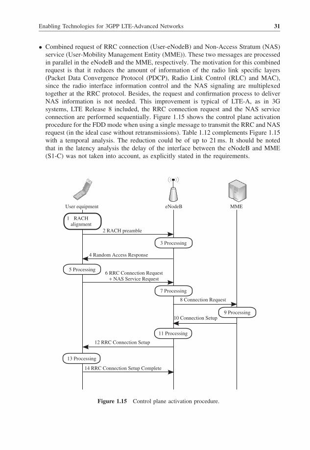
• Combined request of RRC connection (User-eNodeB) and Non-Access Stratum (NAS)service (User-Mobility Management Entity (MME)). These two messages are processedin parallel in the eNodeB and the MME, respectively. The motivation for this combinedrequest is that it reduces the amount of information of the radio link specific layers(Packet Data Convergence Protocol (PDCP), Radio Link Control (RLC) and MAC),since the radio interface information control and the NAS signaling are multiplexedtogether at the RRC protocol. Besides, the request and confirmation process to deliverNAS information is not needed. This improvement is typical of LTE-A, as in 3Gsystems, LTE Release 8 included, the RRC connection request and the NAS serviceconnection are performed sequentially. Figure 1.15 shows the control plane activationprocedure for the FDD mode when using a single message to transmit the RRC and NASrequest (in the ideal case without retransmissions). Table 1.12 complements Figure 1.15with a temporal analysis. The reduction could be of up to 21 ms. It should be notedthat in the latency analysis the delay of the interface between the eNodeB and MME(S1-C) was not taken into account, as explicitly stated in the requirements.
User equipment eNodeB MME
RACHalignment
2 RACH preamble
4 Random Access Response
3 Processing
5 Processing
7 Processing
9 Processing
11 Processing
13 Processing
6 RRC Connection Request+ NAS Service Request
8 Connection Request
10 Connection Setup
12 RRC Connection Setup
14 RRC Connection Setup Complete
1
Figure 1.15 Control plane activation procedure.
32 LTE-Advanced and Next Generation Wireless Networks
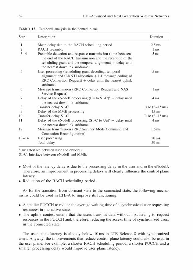
Table 1.12 Temporal analysis in the control plane
Step Description Duration
1 Mean delay due to the RACH scheduling period 2.5 ms2 RACH preamble 1 ms3–4 Preamble detection and response transmission (time between
the end of the RACH transmission and the reception of thescheduling grant and the temporal alignment) + delay untilthe nearest downlink subframe
5 ms
5 User processing (scheduling grant decoding, temporalalignment and C-RNTI allocation + L1 message coding ofRRC Connection Request) + delay until the nearest uplinksubframe
5 ms
6 Message transmission (RRC Connection Request and NASService Request)
1 ms
7 Delay of the eNodeB processing (Uu to S1-C)∗ + delay untilthe nearest downlink subframe
4 ms
8 Transfer delay S1-C Ts1c (2–15 ms)9 Delay of the MME processing 15 ms
10 Transfer delay S1-C Ts1c (2–15 ms)11 Delay of the eNodeB processing (S1-C to Uu)∗ + delay until
the nearest downlink subframe4 ms
12 Message transmission (RRC Security Mode Command andConnection Reconfiguration)
1.5 ms
13–14 User processing 20 msTotal delay 59 ms
∗Uu: Interface between user and eNodeB.S1-C: Interface between eNodeB and MME.
• Most of the latency delay is due to the processing delay in the user and in the eNodeB.Therefore, an improvement in processing delays will clearly influence the control planelatency.
• Reduction of the RACH scheduling period.
As for the transition from dormant state to the connected state, the following mecha-nisms could be used in LTE-A to improve its functioning:
• A smaller PUCCH to reduce the average waiting time of a synchronized user requestingresources in the active state.
• The uplink contest entails that the users transmit data without first having to requestresources in the PUCCH and, therefore, reducing the access time of synchronized usersin the connected state.
The user plane latency is already below 10 ms in LTE Release 8 with synchronizedusers. Anyway, the improvements that reduce control plane latency could also be used inthe user plane. For example, a shorter RACH scheduling period, a shorter PUCCH and asmaller processing delay would improve user plane latency.
Enabling Technologies for 3GPP LTE-Advanced Networks 33
1.5 Summary
This chapter has shown the technological revolution posed by new IMT-Advanced tech-nologies and their evolution. Compared to current systems, IMT-Advanced technologiesinclude a greater bandwidth, new network elements, like relays or femtocells, M2M com-munications and coordination between transmitters. The channel models that have beenused traditionally are no longer valid to analyze all these technological features. Con-sequently, in the last years there has been significant research activity to develop newchannel and propagation models adapted to the new paradigms of wireless communica-tions. The rest of the book addresses this specific issue.
References1. UIT-R, “Framework for services supported by IMT”, UIT, Recommendation M.1822, 2007.2. UIT-R, “Requirements related to technical performance for IMT-Advanced radio interface(s)”, UIT, Report
M.2134, 2008.3. 3GPP, “Physical Channels and Modulation (Release 9)”, 3GPP, Technical Specification TR 36.211 v9.1.0.4. 3GPP, “FDD RIT component of SRIT LTE Release 10 & beyond (LTE-Advanced)”, 3GPP, Report
RP-090745.5. 3GPP, “FDD RIT component of SRIT LTE Release 10 & beyond (LTE-Advanced)”, 3GPP, Report
RP-090746.6. 3GPP, “FDD RIT component of SRIT LTE Release 10 & beyond (LTE-Advanced)”, 3GPP, Report
RP-090747.7. 3GPP, “Feasibility study for Further Advancements for EUTRAs (LTE-Advanced) (Release 9)”, 3GPP,
Technical Report TR 36.912 v9.0.0.8. 3GPP, “Requirements for further advancements for Evolved Universal Terrestrial Radio Access
(E-UTRA) (LTE-Advanced) (Release 9)”, 3GPP, Technical Report TR 36.913 v9.0.0.9. 3GPP, “Physical layer aspects for evolved Universal Terrestrial Radio Access (UTRA) (Release 7)”, 3GPP,
Technical Report TR 25.814 v7.1.0.10. 3GPP, “Feasibility study for evolved Universal Terrestrial Radio Access (UTRA) and Universal Terrestrial
Radio Access Network (UTRAN) (Release 9)”, 3GPP, Technical Report TR 25.912 v9.0.0.11. 3GPP, “Further advancements for E-UTRA; LTE-Advanced feasibility studies in RAN WG4 (Release 9)”,
3GPP, Technical Report TR 36.815 v9.1.0.12. 3GPP, “Cubic Metric in 3GPP-LTE”, 3GPP, Report R1-060385.13. 3GPP, “Cubic Metric comparison of OFDMA and Clustered-DFTS-OFDM/NxDFTS-OFDM”, 3GPP,
Report R1-084469.14. 3GPP, “Further advancements for E-UTRA physical layer aspects (Release 9)”, 3GPP, Technical Report
TR 36.814 v9.0.0.15. 3GPP, “Evolved Universal Terrestrial Radio Access (E-UTRA) and Evolved Universal Terrestrial Radio
Access Network (E-UTRAN); Overall description”, 3GPP, Technical Report TR 36.300 v9.0.0.