Embed Size (px)
Citation preview

Troubleshooting
SECTION 06 Troubleshooting
1/54
Troubleshooting
Troubleshooting
SECTION 06 Troubleshooting
2/54
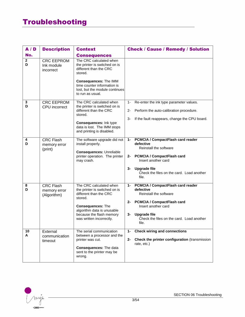
■ Troubleshooting.
The first thing to do is read the help message displayed on the printer.
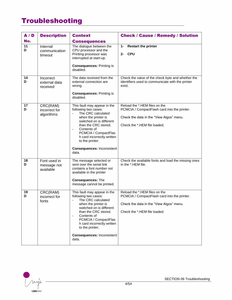
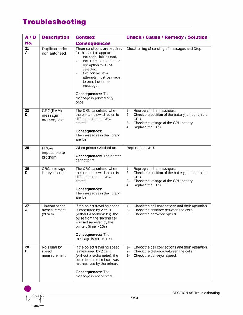
The table on the following pages provides details about the circumstances surrounding each alarm or fault displayed.
The first column gives the number (in ascending order) and type of each alarm or fault:
A: alarm, printing may continue
D: fault, printing disabled
The third column lists checks, causes, remedies and solutions by order of probability. There is generally only one cause of a fault.
Maintenance procedures for solving several faults are described in detail on the pages following the table.
These procedures are:
Solenoid valve test
Releasing solenoid valve 0
Releasing solenoid valves 5 and 6
Partial drain
Full drain
Rinsing the ink circuit
Auto-calibration
Troubleshooting
SECTION 06 Troubleshooting
3/54
A / D
No.
Description Context
Consequences
Check / Cause / Remedy / Solution
2 D
CRC EEPROM Ink module incorrect
The CRC calculated when the printer is switched on is different than the CRC stored. Consequences: The IMM
time counter information is lost, but the module continues to run as usual.
3 D
CRC EEPROM CPU incorrect
The CRC calculated when the printer is switched on is different than the CRC stored. Consequences: Ink type
data is lost. The IMM stops and printing is disabled.
1- Re-enter the ink type parameter values. 2- Perform the auto-calibration procedure. 3- If the fault reappears, change the CPU board.
4 D
CRC Flash memory error (print)
The software upgrade did not install properly. Consequences: Unreliable
printer operation. The printer may crash.
1- PCMCIA / CompactFlash card reader defective
Reinstall the software
2- PCMCIA / CompactFlash card
Insert another card
3- Upgrade file
Check the files on the card. Load another file.
8 D
CRC Flash memory error (Algorithm)
The CRC calculated when the printer is switched on is different than the CRC stored. Consequences: The
algorithm data is unusable because the flash memory was written incorrectly.
1- PCMCIA / CompactFlash card reader defective
Reinstall the software
2- PCMCIA / CompactFlash card
Insert another card
3- Upgrade file
Check the files on the card. Load another file.
10 A
External communication timeout
The serial communication between a processor and the printer was cut.
Consequences: The data
sent to the printer may be wrong.
1- Check wiring and connections 2- Check the printer configuration (transmission
rate, etc.)
Troubleshooting
SECTION 06 Troubleshooting
4/54
A / D
No.
Description Context
Consequences
Check / Cause / Remedy / Solution
11 D
Internal communication timeout
The dialogue between the CPU processor and the Printing processor was interrupted at start-up.
Consequences: Printing is
disabled.
1- Restart the printer 2- CPU
14 D
Incorrect external data received
The data received from the external connection are wrong. Consequences: Printing is
disabled.
Check the value of the check byte and whether the identifiers used to communicate with the printer exist.
17 D
CRC(RAM) incorrect for algorithms
This fault may appear in the following two cases: - The CRC calculated
when the printer is switched on is different than the CRC stored.
- Contents of PCMCIA / CompactFlash card incorrectly written to the printer.
Consequences: Inconsistent
data.
Reload the *.HEM files on the PCMCIA / CompactFlash card into the printer. Check the data in the “View Algos” menu. Check the *.HEM file loaded.
18 D
Font used in message not available
The message selected or sent over the serial link contains a font number not available in the printer
Consequences: The
message cannot be printed.
Check the available fonts and load the missing ones in the *.HEM file.
19 D
CRC(RAM) incorrect for fonts
This fault may appear in the following two cases: - The CRC calculated
when the printer is switched on is different than the CRC stored.
- Contents of PCMCIA / CompactFlash card incorrectly written to the printer.
Consequences: Inconsistent
data.
Reload the *.HEM files on the PCMCIA / CompactFlash card into the printer. Check the data in the “View Algos” menu. Check the *.HEM file loaded.
Troubleshooting
SECTION 06 Troubleshooting
5/54
A / D
No.
Description Context
Consequences
Check / Cause / Remedy / Solution
21 A
Duplicate print non autorised
Three conditions are required for this fault to appear: - the serial link is used. - the “Print-out no double
up” option must be selected.
- two consecutive attempts must be made to print the same message.
Consequences: The
message is printed only once.
Check timing of sending of messages and Dtop.
22 D
CRC(RAM) message memory lost
The CRC calculated when the printer is switched on is different than the CRC stored. Consequences:
The messages in the library are lost.
1- Reprogram the messages. 2- Check the position of the battery jumper on the
CPU. 3- Check the voltage of the CPU battery. 4- Replace the CPU.
25
FPGA impossible to program
When printer switched on. Consequences: The printer
cannot print.
Replace the CPU.
26 D
CRC message library incorrect
The CRC calculated when the printer is switched on is different than the CRC stored. Consequences:
The messages in the library are lost.
1- Reprogram the messages. 2- Check the position of the battery jumper on the
CPU. 3- Check the voltage of the CPU battery. 4- Replace the CPU
27 A
Timeout speed meassurement (20sec)
If the object traveling speed is measured by 2 cells (without a tachometer), the pulse from the second cell was not received by the printer. (time > 20s) Consequences: The
message is not printed.
1- Check the cell connections and their operation. 2- Check the distance between the cells. 3- Check the conveyor speed.
28 D
No signal for speed meassurement
If the object traveling speed is measured by 2 cells (without a tachometer), the pulse from the first cell was not received by the printer. Consequences: The
message is not printed.
1- Check the cell connections and their operation. 2- Check the distance between the cells. 3- Check the conveyor speed.
Troubleshooting
SECTION 06 Troubleshooting
6/54
A / D
No.
Description Context
Consequences
Check / Cause / Remedy / Solution
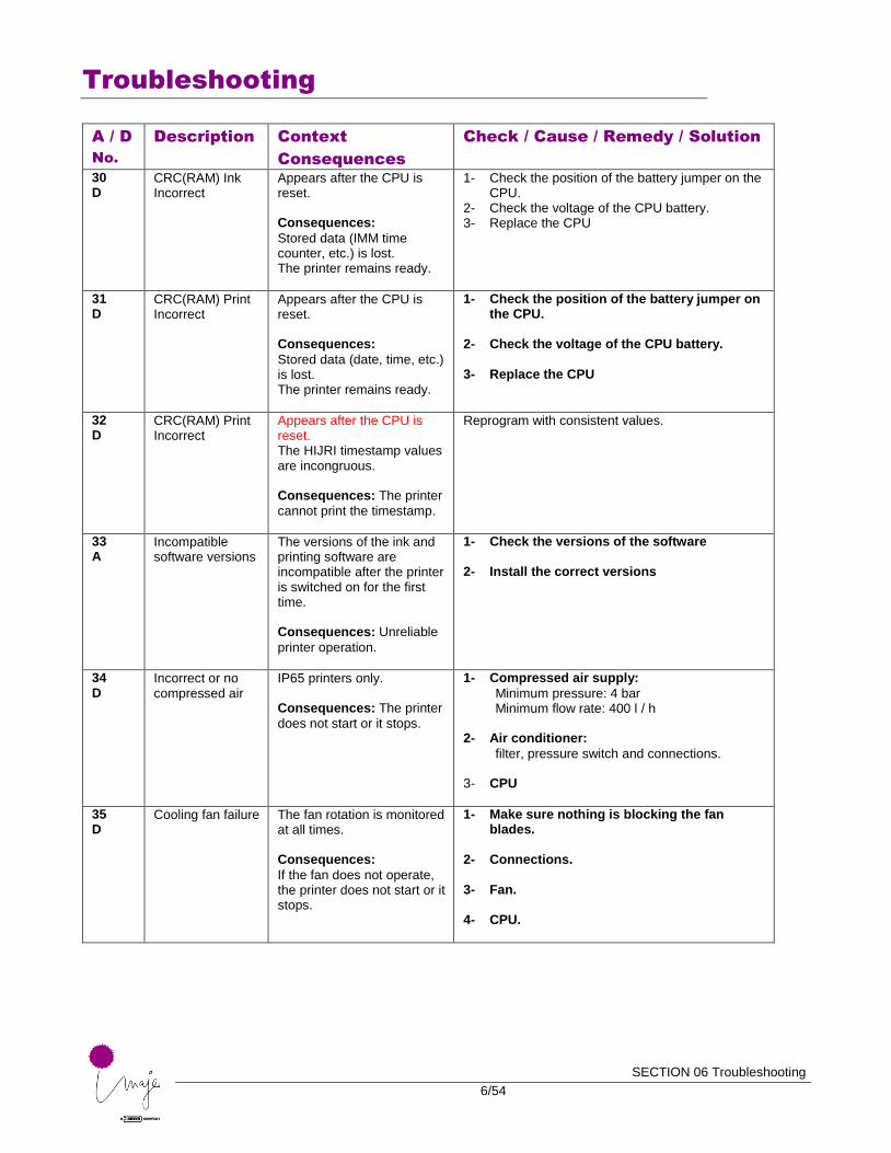
30 D
CRC(RAM) Ink Incorrect
Appears after the CPU is reset. Consequences:
Stored data (IMM time counter, etc.) is lost. The printer remains ready.
1- Check the position of the battery jumper on the CPU.
2- Check the voltage of the CPU battery. 3- Replace the CPU
31 D
CRC(RAM) Print Incorrect
Appears after the CPU is reset. Consequences:
Stored data (date, time, etc.) is lost. The printer remains ready.
1- Check the position of the battery jumper on the CPU.
2- Check the voltage of the CPU battery.
3- Replace the CPU
32 D
CRC(RAM) Print Incorrect
Appears after the CPU is reset. The HIJRI timestamp values are incongruous. Consequences: The printer
cannot print the timestamp.
Reprogram with consistent values.
33 A
Incompatible software versions
The versions of the ink and printing software are incompatible after the printer is switched on for the first time. Consequences: Unreliable
printer operation.
1- Check the versions of the software 2- Install the correct versions
34 D
Incorrect or no compressed air
IP65 printers only. Consequences: The printer
does not start or it stops.
1- Compressed air supply:
Minimum pressure: 4 bar Minimum flow rate: 400 l / h
2- Air conditioner:
filter, pressure switch and connections. 3- CPU
35 D
Cooling fan failure The fan rotation is monitored at all times. Consequences:
If the fan does not operate, the printer does not start or it stops.
1- Make sure nothing is blocking the fan blades.
2- Connections.
3- Fan.
4- CPU.
Troubleshooting
SECTION 06 Troubleshooting
7/54
A / D
No.
Description Context
Consequences
Check / Cause / Remedy / Solution
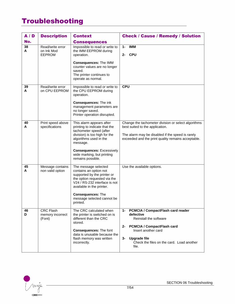
38 A
Read/write error on Ink Mod EEPROM
Impossible to read or write to the IMM EEPROM during operation. Consequences: The IMM
counter values are no longer saved. The printer continues to operate as normal.
1- IMM 2- CPU
39 A
Read/write error on CPU EEPROM
Impossible to read or write to the CPU EEPROM during operation. Consequences: The ink
management parameters are no longer saved. Printer operation disrupted.
CPU
40 A
Print speed above specifications
This alarm appears after printing to indicate that the tachometer speed (after division) is too high for the algorithms used in the message. Consequences: Excessively
wide marking, but printing remains possible.
Change the tachometer division or select algorithms best suited to the application. The alarm may be disabled if the speed is rarely exceeded and the print quality remains acceptable.
45 A
Message contains non valid option
The message selected contains an option not supported by the printer or the option requested via the V24 / RS-232 interface is not available in the printer. Consequences: The
message selected cannot be printed.
Use the available options.
46 D
CRC Flash memory incorrect (Font)
The CRC calculated when the printer is switched on is different than the CRC stored. Consequences: The font
data is unusable because the flash memory was written incorrectly.
1- PCMCIA / CompactFlash card reader defective
Reinstall the software
2- PCMCIA / CompactFlash card
Insert another card
3- Upgrade file
Check the files on the card. Load another file.

Troubleshooting
SECTION 06 Troubleshooting
8/54
A / D
No.
Description Context
Consequences
Check / Cause / Remedy / Solution
48 D
Algorithm not available
The message selected or sent over the serial link contains an algorithm number not available in the printer.
Consequences: The
message cannot be printed.
Check the algorithms available and load the missing ones in the *.HEM file.
50 A
LOW INK level. Prepare new cartridge
The ink level in the cartridge is calculated by the software using the negative pressure value and the number of times the cartridge has been pumped. Warning: The indication
given by pictogram F6 may be distorted if the cartridge has not been correctly replaced (full cartridge, cartridge with sufficient capacity, etc.).
1- Cartridge
- Small amount of ink remaining in cartridge - Correctly positioned in cartridge holder - Properly perforated tip O-ring
2- Ink solenoid valve 0
- Test - Replace the IMM 3- Clogged hollow needle
Remove the tip holder and clean the needle with clean additive or replace the tip holder. 4- CPU
51 A
LOW ADDITIVE. Prepare new cartridge
The level of additive in the cartridge is calculated by the software using the negative pressure value and the number of times the cartridge has been pumped. Warning: The indication
given by pictogram F7 may be distorted if the cartridge has not been correctly replaced (full cartridge, cartridge with sufficient capacity, etc.).
1- Cartridge
- Small amount of additive remaining - Correctly positioned in cartridge holder - Properly perforated tip O-ring
2- Additive solenoid valve 1
- Test - Replace the IMM 3- Clogged or bent hollow needle
Remove the tip holder and clean or replace it.
4- CPU
52 A
EMPTY INK Cartridge
After several attempts to pump ink from the cartridge, the printer indicates that the cartridge is empty. Consequences:
Printing is still possible but only until the ink in the accumulator runs out.
1- Cartridge
- Not empty - Correctly positioned in cartridge holder - Properly perforated tip O-ring
2- Ink solenoid valve 0
- Test - Replace the IMM 3- Clogged hollow needle
Remove the tip holder and clean the needle with clean additive or replace the tip holder. 4- CPU
Troubleshooting
SECTION 06 Troubleshooting
9/54
A / D
No.
Description Context
Consequences
Check / Cause / Remedy / Solution
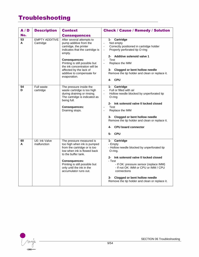
53 A
EMPTY ADDITIVE Cartridge
After several attempts to pump additive from the cartridge, the printer indicates that the cartridge is empty. Consequences:
Printing is still possible but the ink concentration will be affected by the lack of additive to compensate for evaporation.
1- Cartridge
- Not empty - Correctly positioned in cartridge holder - Properly perforated tip O-ring
2- Additive solenoid valve 1
- Test - Replace the IMM
3- Clogged or bent hollow needle
Remove the tip holder and clean or replace it. 4- CPU
54 D
Full waste cartridge
The pressure inside the waste cartridge is too high during draining or rinsing. The cartridge is indicated as being full. Consequences:
Draining stops.
1- Cartridge
- Full or filled with air - Hollow needle blocked by unperforated tip
O-ring
2- Ink solenoid valve 0 locked closed
- Test - Replace the IMM
3- Clogged or bent hollow needle
Remove the tip holder and clean or replace it. 4- CPU board connector 5- CPU
60 A
U0: Ink Valve malfunction
The pressure measured is too high when ink is pumped from the cartridge or is too low when ink is flowed back to the buffer tank. Consequences:
Printing is still possible but only until the ink in the accumulator runs out.
1- Cartridge
- Empty - Hollow needle blocked by unperforated tip O-ring.
2- Ink solenoid valve 0 locked closed
- Test - If OK: pressure sensor (replace IMM) - If not OK: IMM or CPU or IMM / CPU connections
3- Clogged or bent hollow needle
Remove the tip holder and clean or replace it.
Troubleshooting
SECTION 06 Troubleshooting
10/54
A / D
No.
Description Context
Consequences
Check / Cause / Remedy / Solution
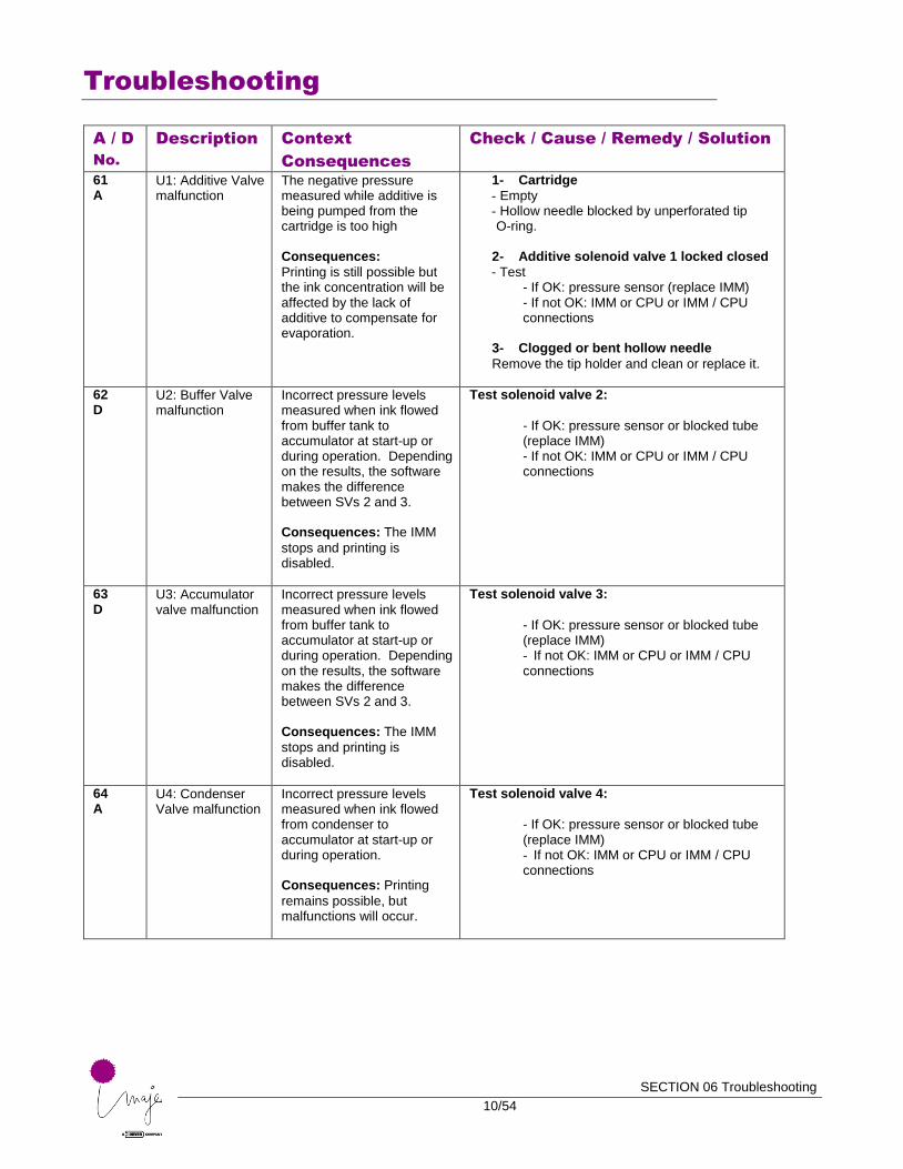
61 A
U1: Additive Valve malfunction
The negative pressure measured while additive is being pumped from the cartridge is too high Consequences:
Printing is still possible but the ink concentration will be affected by the lack of additive to compensate for evaporation.
1- Cartridge
- Empty - Hollow needle blocked by unperforated tip O-ring.
2- Additive solenoid valve 1 locked closed
- Test - If OK: pressure sensor (replace IMM) - If not OK: IMM or CPU or IMM / CPU connections
3- Clogged or bent hollow needle
Remove the tip holder and clean or replace it.
62 D
U2: Buffer Valve malfunction
Incorrect pressure levels measured when ink flowed from buffer tank to accumulator at start-up or during operation. Depending on the results, the software makes the difference between SVs 2 and 3. Consequences: The IMM
stops and printing is disabled.
Test solenoid valve 2:
- If OK: pressure sensor or blocked tube (replace IMM) - If not OK: IMM or CPU or IMM / CPU connections
63 D
U3: Accumulator valve malfunction
Incorrect pressure levels measured when ink flowed from buffer tank to accumulator at start-up or during operation. Depending on the results, the software makes the difference between SVs 2 and 3. Consequences: The IMM
stops and printing is disabled.
Test solenoid valve 3:
- If OK: pressure sensor or blocked tube (replace IMM) - If not OK: IMM or CPU or IMM / CPU connections
64 A
U4: Condenser Valve malfunction
Incorrect pressure levels measured when ink flowed from condenser to accumulator at start-up or during operation. Consequences: Printing
remains possible, but malfunctions will occur.
Test solenoid valve 4:
- If OK: pressure sensor or blocked tube (replace IMM) - If not OK: IMM or CPU or IMM / CPU connections
Troubleshooting
SECTION 06 Troubleshooting
11/54
A / D
No.
Description Context
Consequences
Check / Cause / Remedy / Solution
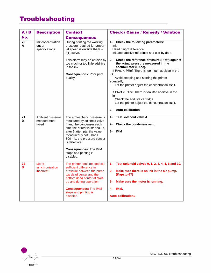
70 A
Ink concentration out of specifications
During printing the working pressure required for proper jet speed is outside the P = f(T) curve. This alarm may be caused by too much or too little additive in the ink. Consequences: Poor print
quality.
1- Check the following parameters:
Ink Head height difference Ink and additive reference and use-by date.
2- Check the reference pressure (PRef) against
the actual pressure measured in the accumulator (PAcc).
If PAcc < PRef: There is too much additive in the ink.
Avoid stopping and starting the printer repeatedly.
Let the printer adjust the concentration itself.
If PRef < PAcc: There is too little additive in the ink.
Check the additive cartridge Let the printer adjust the concentration itself.
3- Auto-calibration
71 D
Ambient pressure measurement failed
The atmospheric pressure is measured by solenoid valve 4 and the condenser each time the printer is started. If, after 3 attempts, the value measured is not 0 bar ± 300 mb, the pressure sensor is defective. Consequences: The IMM
stops and printing is disabled.
1- Test solenoid valve 4 2- Check the condenser vent
3- IMM
72 D
Motor synchronisation incorrect
The printer does not detect a sufficient difference in pressure between the pump top dead center and the bottom dead center at start-up and during operation. Consequences: The IMM
stops and printing is disabled.
1- Test solenoid valves 0, 1, 2, 3, 4, 5, 6 and 10. 2- Make sure there is no ink in the air pump.
(Kapsto 6?) 3- Make sure the motor is running.
4- IMM. Auto-calibration?
Troubleshooting
SECTION 06 Troubleshooting
12/54
A / D
No.
Description Context
Consequences
Check / Cause / Remedy / Solution
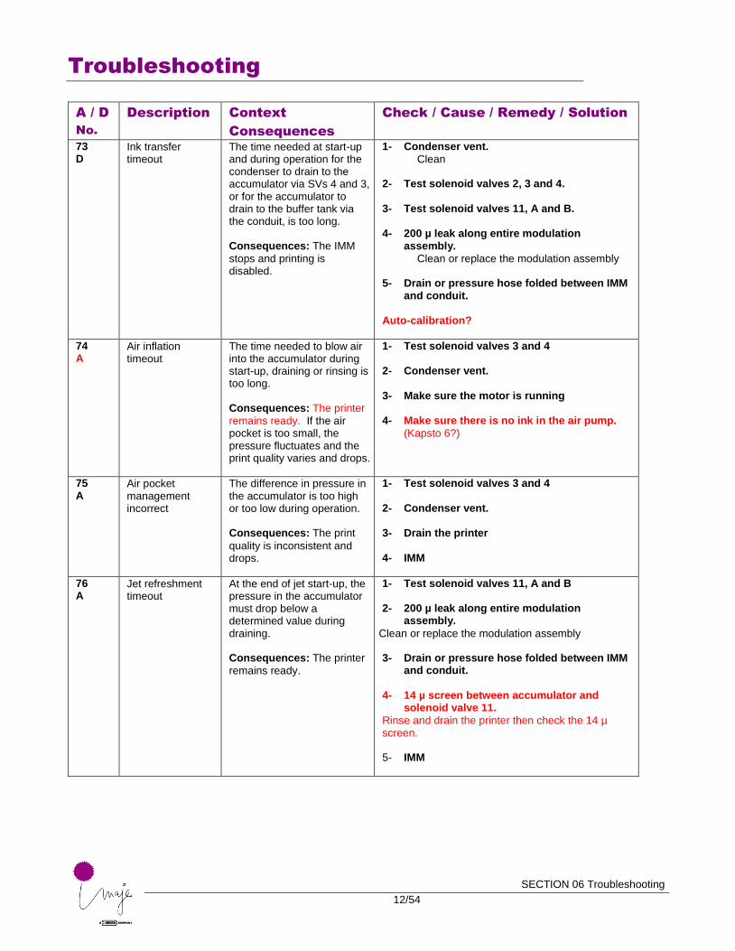
73 D
Ink transfer timeout
The time needed at start-up and during operation for the condenser to drain to the accumulator via SVs 4 and 3, or for the accumulator to drain to the buffer tank via the conduit, is too long. Consequences: The IMM
stops and printing is disabled.
1- Condenser vent.
Clean 2- Test solenoid valves 2, 3 and 4. 3- Test solenoid valves 11, A and B.
4- 200 µ leak along entire modulation
assembly.
Clean or replace the modulation assembly 5- Drain or pressure hose folded between IMM
and conduit. Auto-calibration?
74 A
Air inflation timeout
The time needed to blow air into the accumulator during start-up, draining or rinsing is too long. Consequences: The printer
remains ready. If the air pocket is too small, the pressure fluctuates and the print quality varies and drops.
1- Test solenoid valves 3 and 4 2- Condenser vent.
3- Make sure the motor is running
4- Make sure there is no ink in the air pump.
(Kapsto 6?)
75 A
Air pocket management incorrect
The difference in pressure in the accumulator is too high or too low during operation. Consequences: The print
quality is inconsistent and drops.
1- Test solenoid valves 3 and 4 2- Condenser vent.
3- Drain the printer
4- IMM
76 A
Jet refreshment timeout
At the end of jet start-up, the pressure in the accumulator must drop below a determined value during draining. Consequences: The printer
remains ready.
1- Test solenoid valves 11, A and B 2- 200 µ leak along entire modulation
assembly.
Clean or replace the modulation assembly 3- Drain or pressure hose folded between IMM
and conduit. 4- 14 µ screen between accumulator and
solenoid valve 11.
Rinse and drain the printer then check the 14 µ screen. 5- IMM
Troubleshooting
SECTION 06 Troubleshooting
13/54
A / D
No.
Description Context
Consequences
Check / Cause / Remedy / Solution
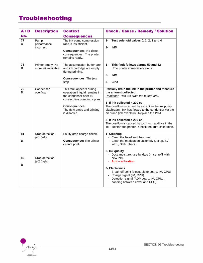
77 A
Pump performance incorrect
The ink pump compression ratio is insufficient. Consequences: No direct
consequences. The printer remains ready.
1- Test solenoid valves 0, 1, 2, 3 and 4 2- IMM
78 D
Printer empty. No more ink available
The accumulator, buffer tank and ink cartridge are empty during printing. Consequences: The jets
stop.
1- This fault follows alarms 50 and 52
The printer immediately stops
2- IMM 3- CPU
79 D
Condenser overflow
This fault appears during operation if liquid remains in the condenser after 10 consecutive pumping cycles. Consequences:
The IMM stops and printing is disabled.
Partially drain the ink in the printer and measure the amount collected. Reminder: This will drain the buffer tank. 1- If ink collected < 200 cc
The overflow is caused by a crack in the ink pump diaphragm. Ink has flowed to the condenser via the air pump (ink overflow). Replace the IMM. 2- If ink collected > 200 cc
The overflow is caused by too much additive in the ink. Restart the printer. Check the auto-calibration.
81 D 82 D
Drop detection jet1 (left) Drop detection jet2 (right)
Faulty drop charge check. Consequence: The printer
cannot print.
1- Cleaning
- Clean the head and the cover - Clean the modulation assembly (Jet tip, SV
intro., Stab. check) 2- Ink quality
- Dust, moisture, use-by date (rinse, refill with new ink)
- Auto-calibration
3- Electronics
- Break-off point (piezo, piezo board, IM, CPU) - Charge signal (IM, CPU) - Detection signal (ADP board, IM, CPU, ,
bonding between cover and CPU)
Troubleshooting
SECTION 06 Troubleshooting
14/54
A / D
No.
Description Context
Consequences
Check / Cause / Remedy / Solution
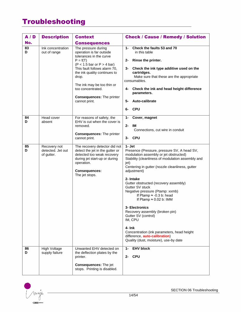
83 D
Ink concentration out of range
The pressure during operation is far outside tolerances in the curve P = f(T) (P < 1.5 bar or P > 4 bar) This fault follows alarm 70, the ink quality continues to drop. The ink may be too thin or too concentrated. Consequences: The printer
cannot print.
1- Check the faults 53 and 70
in this table 2- Rinse the printer. 3- Check the ink type additive used on the
cartridges.
Make sure that these are the appropriate consumables.
4- Check the ink and head height difference
parameters. 5- Auto-calibrate
6- CPU
84 D
Head cover absent
For reasons of safety, the EHV is cut when the cover is removed. Consequences: The printer
cannot print.
1- Cover, magnet 2- IM
Connections, cut wire in conduit
3- CPU
85 D
Recovery not detected. Jet out of gutter.
The recovery detector did not detect the jet in the gutter or detected too weak recovery during jet start-up or during operation. Consequences:
The jet stops.
1- Jet
Presence (Pressure, pressure SV, A head SV, modulation assembly or jet obstructed) Stability (cleanliness of modulation assembly and jet) Centering in gutter (nozzle cleanliness, gutter adjustment) 2- Intake
Gutter obstructed (recovery assembly) Gutter SV stuck Negative pressure (Ptamp: xxmb)
If Ptamp ≈ -0.3 b: head If Ptamp ≈ 0.02 b: IMM
3- Electronics
Recovery assembly (broken pin) Gutter SV (control) IM, CPU 4- Ink
Concentration (ink parameters, head height difference, auto-calibration)
Quality (dust, moisture), use-by date
86 D
High Voltage supply failure
Unwanted EHV detected on the deflection plates by the printer. Consequences: The jet
stops. Printing is disabled.
1- EHV block 2- CPU
Troubleshooting
SECTION 06 Troubleshooting
15/54
A / D
No.
Description Context
Consequences
Check / Cause / Remedy / Solution
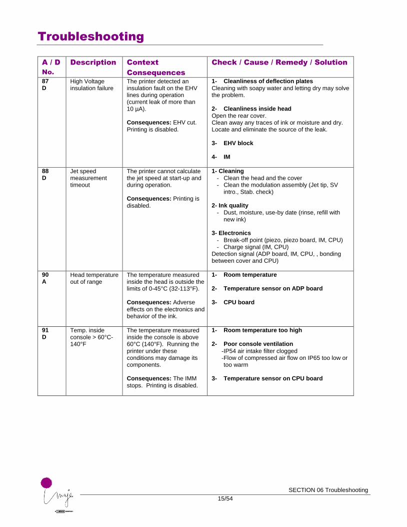
87 D
High Voltage insulation failure
The printer detected an insulation fault on the EHV lines during operation (current leak of more than 10 µA). Consequences: EHV cut.
Printing is disabled.
1- Cleanliness of deflection plates
Cleaning with soapy water and letting dry may solve the problem. 2- Cleanliness inside head
Open the rear cover. Clean away any traces of ink or moisture and dry. Locate and eliminate the source of the leak. 3- EHV block
4- IM
88 D
Jet speed measurement timeout
The printer cannot calculate the jet speed at start-up and during operation. Consequences: Printing is
disabled.
1- Cleaning
- Clean the head and the cover - Clean the modulation assembly (Jet tip, SV
intro., Stab. check) 2- Ink quality
- Dust, moisture, use-by date (rinse, refill with new ink)
3- Electronics
- Break-off point (piezo, piezo board, IM, CPU) - Charge signal (IM, CPU)
Detection signal (ADP board, IM, CPU, , bonding between cover and CPU)
90 A
Head temperature out of range
The temperature measured inside the head is outside the limits of 0-45°C (32-113°F). Consequences: Adverse
effects on the electronics and behavior of the ink.
1- Room temperature 2- Temperature sensor on ADP board
3- CPU board
91 D
Temp. inside console > 60°C-140°F
The temperature measured inside the console is above 60°C (140°F). Running the printer under these conditions may damage its components. Consequences: The IMM
stops. Printing is disabled.
1- Room temperature too high 2- Poor console ventilation
- IP54 air intake filter clogged - Flow of compressed air flow on IP65 too low or too warm
3- Temperature sensor on CPU board
Troubleshooting
SECTION 06 Troubleshooting
16/54
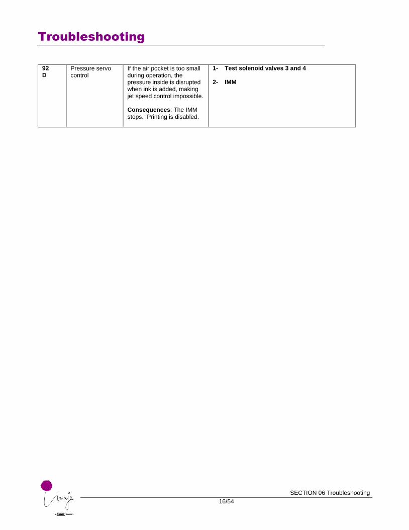
92 D
Pressure servo control
If the air pocket is too small during operation, the pressure inside is disrupted when ink is added, making jet speed control impossible. Consequences: The IMM
stops. Printing is disabled.
1- Test solenoid valves 3 and 4 2- IMM
Troubleshooting
SECTION 06 Troubleshooting
17/54
■ Maintenance procedures
Solenoid valve test.
The “Test solenoid valves” function makes it possible not only to know (by listening) whether a solenoid valve responds to a command signal, but also to release a stuck solenoid valve by actuating it several times.
WARNING: Ink or additive may splash out during the procedure. Take precautions, and wear gloves and safety glasses.
All the ink circuit and head solenoid valves are accessible via this function and can be individually controlled.
WARNING: Some combinations are prohibited. Example: U3 and U1 open at the same time.
COMMENT: The single control (U9) actuating solenoid valves 5 and 6 in turn is no longer available.
COMMENT: On a valve-controlled ink circuit, solenoid valves 5 and 6 are replaced by valves. Controls U5 and U6 therefore do not function (no clicking).

Troubleshooting
SECTION 06 Troubleshooting
18/54
Releasing solenoid valve 0
WARNING: Ink or additive may splash out during the procedure. Take precautions, and wear gloves and safety glasses.
COMMENT: It is not necessary to remove the IMM from the console to release solenoid valve 0.
Turn the printer On and select “Test ink solenoid valve U0”.
Open the right side door.
Remove the ink and additive cartridges.
Remove the cartridge support plate.
Remove the ink tip holder and check the needle for any clogs. Clean if necessary with additive.
Protect the inside of the console under the IMM with absorbent paper or a cloth.
Using the cleaning flask, insert additive into the solenoid valve conduit while actuating it (press and hold “test solenoid valve” until the valve releases).
Clean and dry the tip holder, change the O-ring and put the holder back in place.
Troubleshooting
SECTION 06 Troubleshooting
19/54
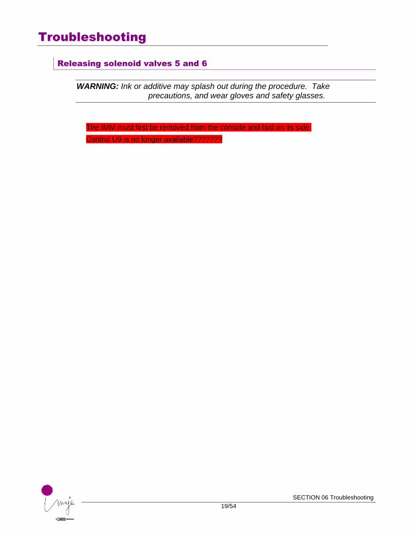
Releasing solenoid valves 5 and 6
WARNING: Ink or additive may splash out during the procedure. Take precautions, and wear gloves and safety glasses.
The IMM must first be removed from the console and laid on its side.
Control U9 is no longer available???????
Troubleshooting
SECTION 06 Troubleshooting
20/54
Partial drain
This will empty the ink in the buffer tank without rinsing it.
A depressurized empty cartridge is necessary.
Follow the instructions that appear on the screen.
WARNING: Follow the instructions carefully to avoid spilling any fluid. Wear gloves and safety glasses.
Full drain
This will drain all the ink out of the printer without rinsing it.
A depressurized empty cartridge is necessary.
Follow the instructions that appear on the screen.
WARNING: Follow the instructions carefully to avoid spilling any fluid. Wear gloves and safety glasses.
Rinsing the ink circuit
Rinse the ink circuit in the following cases:
□ before a protracted period of non-use
□ to correct certain faults
□ before replacing the IMM (where possible)
This procedure drains the printer completely then rinses it with additive. Two depressurized empty cartridges are necessary.
Follow the instructions that appear on the screen.
WARNING: Follow the instructions carefully to avoid spilling any fluid. Wear gloves and safety glasses.
Troubleshooting
SECTION 06 Troubleshooting
21/54
Auto-calibration.
■ When to perform auto-calibration
□ After replacing the IM
□ After replacing the CPU
□ After replacing the IMM
■ Why perform auto-calibration
The jet speed control ensures print quality over time. The control depends on the ink type and several printer components (such as the printing module and the ink management module).
Once the printer is assembled and loaded with ink, the auto-calibration procedure calibrates the control system.
■ Performing auto-calibration
After checking the installation parameters (head height difference), calibrate using ink with the appropriate concentration.
When the jet reaches its rated speed, the auto-calibration validation positions the curve Pressure = f(Temperature).
■ Procedure
Printer empty and stopped.
Connect a new ink cartridge at the same temperature as the printer.
Remove the additive cartridge.
Start the printer (faults 51 and 53 appear).
Check or enter the head height difference and ink type parameters.
WARNING: The head height difference must match the actual difference during auto-calibration.
REMINDER: the head height difference is the distance between the middle of the head and the middle of the console.
NOTE: If the head is not at the auto-calibration position when the head is placed in the working position, the head height difference must be changed and adjusted.
Troubleshooting
SECTION 06 Troubleshooting
22/54
Do not let the head and jet operate for too long on its maintenance stand if the stand is not at the working position.
Confirm “Auto-calibration: No”.
Start the jet. Wait 10 minutes or so (regardless of the ink type) for the ink temperature to be even.
Enter adjustment mode, check the break-off point and adjust it if necessary.
COMMENT: In adjustment mode, the pressure in the accumulator is at the theoretical value along the reference curve if the ink P = f(T).
Start the jet as if you were going to print. Close the head cover. The jet must be ready to print (green “Jet status” LED lit steady).
COMMENT: Acknowledge all faults and alarms before confirming auto-calibration.
When the jet speed is at its nominal value, confirm “Auto-calibration: Yes”. Check that the reference pressure is the same as the actual pressure.
The printer is now calibrated.
Put the additive cartridge back in place and perform the printing tests.
IMPORTANT: If necessary, adjust the head height difference so that it is the same as the working position.
Troubleshooting
SECTION 06 Troubleshooting
23/54
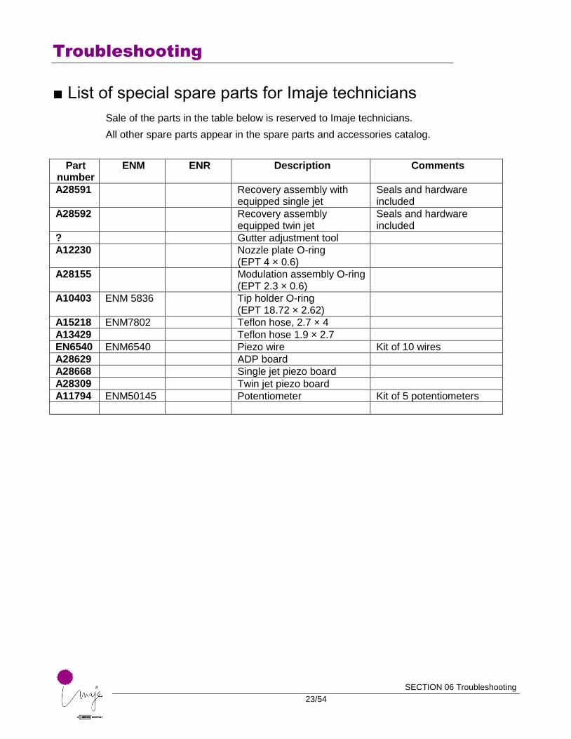
■ List of special spare parts for Imaje technicians
Sale of the parts in the table below is reserved to Imaje technicians.
All other spare parts appear in the spare parts and accessories catalog.
Part number
ENM ENR Description Comments
A28591 Recovery assembly with equipped single jet
Seals and hardware included
A28592 Recovery assembly equipped twin jet
Seals and hardware included
? Gutter adjustment tool
A12230 Nozzle plate O-ring (EPT 4 × 0.6)
A28155 Modulation assembly O-ring (EPT 2.3 × 0.6)
A10403 ENM 5836 Tip holder O-ring (EPT 18.72 × 2.62)
A15218 ENM7802 Teflon hose, 2.7 × 4
A13429 Teflon hose 1.9 × 2.7
EN6540 ENM6540 Piezo wire Kit of 10 wires
A28629 ADP board
A28668 Single jet piezo board
A28309 Twin jet piezo board
A11794 ENM50145 Potentiometer Kit of 5 potentiometers
Troubleshooting
SECTION 06 Troubleshooting
24/54
Spare parts sheets
INTRODUCTORY NOTE: The spare parts sheets (FPR) in this section were written with preventive maintenance in mind.
During curative maintenance it is not always possible to follow the recommended procedures in full (e.g. it might not be possible to drain the ink circuit if a solenoid valve is blocked). In such cases we recommend taking all possible precautions to avoid spilling or splashing ink or additive.
Whenever parts with gaskets are disassembled, new gaskets must always be fitted even if the parts are not replaced.
Troubleshooting
SECTION 06 Troubleshooting
25/54
Replacing a modulator assembly
■ Tools:
1.5 mm Allen wrench
CAUTION: Turn off the printer and unplug it from its AC outlet.
Residual ink may pour out, take appropriate precautions.
Perform this operation in a dust-free environment.
■ Disassembly:
□ Open the head cover. Disassemble the resonator protective cover. Disconnect the resonator wires.
□ Unscrew the two screws holding the modulator assembly and remove it. Take care with the seals (two O-rings).
■ Reassembly:
□ Clean the seal mating surface with additive, remove the old O-rings and fit two new O-rings in their locations on the head.
□ Place the new modulator assembly in position then tighten the two mounting screws.
□ Reconnect the resonator power supply cord and reinstall the protective cover.
■ Testing:
□ Start the printer.
□ A "stability check" is required. Gutter adjustment may be necessary.
Auto-calibration?
Troubleshooting
SECTION 06 Troubleshooting
26/54
Replacing a resonator
■ Tools:
1.5 mm Allen wrench; resonator clamping/loosening rod.
CAUTION: Turn off the printer and unplug it from its AC outlet.
Residual ink may pour out, take appropriate precautions.
Perform this operation in a dust-free environment.
■ Disassembly:
□ Open the head cover. Disassemble the resonator wire protective cover. Disconnect the resonator wires.
□ Unscrew and remove the resonator clamping sleeve.
□ Pull the resonator out of its housing. Take care with the seal (one O-ring).
■ Reassembly:
□ Clean the inside of the modulation chamber with additive. Remove the old O-ring.
□ Fit the new O-ring on the resonator before reassembling it. Tighten the clamping sleeve.
□ Reconnect the resonator wires and reinstall the protective cover.
■ Testing:
□ Start the printer.
□ A stability check and break-off point adjustment are required.
Troubleshooting
SECTION 06 Troubleshooting
27/54
Replacing the nozzle plate.
■ Tools:
1.5 mm Allen wrench; 2.5 mm flat-bladed screwdriver.
CAUTION: Turn off the printer and unplug it from its AC outlet.
Residual ink may pour out, take appropriate precautions.
Perform this operation in a dust-free environment.
■ Disassembly:
□ Open the head cover. Disassemble the resonator protective cover. Disconnect the resonator wires.
□ Unscrew the two screws holding the modulator assembly and remove it. Take care with the seals (two O-rings).
□ Unscrew the two screws from the nozzle plate and remove it. Take care with the seal (one O-ring).
■ Reassembly:
□ Clean the nozzle plate seal mating surface with additive, remove the old O-ring and fit a new one. Reassemble the nozzle plate on the modulator assembly.
□ Clean the modulator assembly seal mating surface with additive, remove the old O-rings and fit two new O-rings in their locations on the head.
□ Place the new modulator assembly in position then tighten the two mounting screws.
□ Reconnect the resonator power supply cord and reinstall the protective cover.
■ Testing:
□ Start the printer.
□ A "stability check" is required. Gutter adjustment may be necessary.
Troubleshooting
SECTION 06 Troubleshooting
28/54
Replacing the 4 solenoid valve block
■ Tools:
1.5 mm Allen wrench.
CAUTION: Turn off the printer and unplug it from its AC outlet.
Position the head higher than the printer console.
Residual ink may pour out, take appropriate precautions.
Perform this operation in a dust-free environment.
■ Disassembly:
□ Open the head rear cover
□ Unscrew the two screws holding the 4 solenoid valve block and remove the block. Take care with seals (one rectangular 3-hole gasket, one square 4-hole gasket)
■ Reassembly:
□ Use solvent to clean the seal mating surface on the 4 solenoid valve block and the contact board.
□ Replace the seals (2 flat gaskets) then replace the solenoid valve block.
■ Testing:
□ Restart the printer before closing the rear cover. Check that there are no leaks.
CAUTION: The solenoid valve block must be replaced if there are any ink leaks (risks of short-circuits on the integrated control ribbon cable).
□ Close the head rear cover.
□ A "stability check" is required.
Troubleshooting
SECTION 06 Troubleshooting
29/54
Replacing the recovery unit
■ Tools:
2.5 mm flat-bladed screwdriver
CAUTION: Turn off the printer and unplug it from its AC outlet.
Residual ink may pour out, take appropriate precautions.
■ Disassembly:
□ Remove the four screws at the corners of the recovery assembly and remove it. Pay attention to the seals (O-rings around pins).
□ Clean the seal mating surface between the head and the recovery unit using additive.
■ Reassembly:
□ Replace the O-ring on the recovery solenoid valve tip.
□ Fit new O-rings around the pins (2 seals for a single-jet head (3 seals for a twin-jet) and fit the new recovery assembly, taking care not to damage the fragile recovery pins. Tighten the four screws.
■ Testing:
□ Restart the printer.
□ Adjust the recovery gutters (see settings sheet).
Troubleshooting
SECTION 06 Troubleshooting
30/54
Replacing a recovery gutter
■ Tools:
0.9 mm Allen wrench, Imaje gutter adjustment tool.
CAUTION: The jet must be stopped.
Residual ink may pour out, take appropriate precautions.
■ Disassembly:
□ Loosen the pressure screw on the same side as the gutter to be replaced, by half a turn.
□ Use the gutter adjustment tool to extract the gutter to be replaced.
□ Use additive to clean the port on the recovery unit.
■ Reassembly:
□ Insert the new gutter in the orifice on the recovery assembly unit and push it fully in.
■ Testing and adjustment:
□ Set the jet to "adjustment" mode.
□ Use the adjustment tool to adjust the gutter (jet in center of gutter).
□ Tighten the pressure screw moderately.
Troubleshooting
SECTION 06 Troubleshooting
31/54
Replacing the recovery solenoid valve
■ Tools:
1.5 mm Allen wrench; 2.5 mm flat-bladed screwdriver; 7 mm box wrench
CAUTION: Turn off the printer and unplug it from its AC outlet.
Position the head higher than the printer console
Residual ink may pour out, take appropriate precautions.
■ Disassembly:
□ Disassemble the rear head cover.
□ Disassemble the 4 solenoid valve block. Take care with seals (one rectangular 3-hole gasket, one square 4-hole gasket)
□ Remove the ground braid screw from the body of the recovery solenoid valve.
□ Disconnect the solenoid valve rinsing hose.
□ To avoid damaging the recovery assembly, loosen the four screws in the corners of the assembly by one full turn (do not loosen the central screw), detach the recovery assembly, remove the four screws and gently remove the recovery assembly by pulling it free in line with the head axis. Pay attention to the seals (O-rings around pins).
CAUTION: The recovery detection pins and contacts are very fragile.
□ Remove the nut (7 mm across flats) then withdraw the recovery solenoid valve.
□ Unsolder the electrical control wires.
□ Slide the sleeve on the intake hose before pulling it free of the solenoid valve. Remove the solenoid valve.
Troubleshooting
SECTION 06 Troubleshooting
32/54
■ Reassembly:
□ Solder the control wires to the new solenoid valve.
□ Connect the intake hose and slide the sleeve.
□ Fit new seals (two O-rings) to the new solenoid valve.
□ Position the solenoid valve in its housing (check that it is oriented correctly) then retighten the nut.
□ Connect the rinsing hose.
□ Screw the two ground lugs back on.
□ Use solvent to clean the seal mating surface on the recovery assembly then replace the seals (O-rings around pins) and replace it.
□ Use solvent to clean the seal mating surface on the 4 solenoid valve block then replace the seals (two gaskets) and replace it.
■ Testing:
□ Restart the head before closing the rear cover. Check that there are no leaks.
□ A "stability check" is required.
Troubleshooting
SECTION 06 Troubleshooting
33/54
Replacing the print module
■ Tools:
2 mm Allen wrench; 2.5 mm Allen wrench.
CAUTION: Rinse and drain the printer then turn it off and unplug it from its AC outlet.
Residual ink may pour out, take appropriate precautions.
■ Disassembly:
□ Open the right side door and remove the ink and additive cartridges.
□ Unscrew the two cartridge guide rods. Loosen the top screw, remove the bottom screw from the cartridge support plate and remove this plate.
□ Uncouple the multi-way hydraulic connector and fit the stopper on the conduit side.
CAUTION: Residual ink may pour out, take appropriate precautions.
□ Open the left side door. Disconnect the head connector from the CPU board and unscrew the conduit ground wire lug.
□ Underneath the printer, unscrew the four conduit mounting screws and withdraw the wires and hoses. Take care with the seal (one O-ring).
■ Reassembly:
□ Fit a new O-ring on the attachment plate then reassemble and connect the conduit (electrical and hydraulic connectors and ground wire).
CAUTION: the hoses must not obstruct the fan.
□ Reassemble the cartridge support plate.
Testing:
□ Restart the printer.
□ Autocalibration is required (see procedure).
Troubleshooting
SECTION 06 Troubleshooting
34/54
Replacing the ink management module
■ Tools:
5 mm Allen wrench; 2.5 mm Allen wrench.
CAUTION: Rinse and drain the printer then turn it off and unplug it from its AC outlet.
If you are unable to use the automatic "Drain/rinse" function due to problems on the ink circuit you may use the procedure below to drain the ink management module manually.
■ Disassembly:
□ Open the right side door and remove the ink and additive cartridges.
□ Unscrew the two cartridge guide rods. Remove the cartridge support plate (two screws).
□ Position the print head lower than the ink circuit.
□ Remove the hydraulic connector from the console without uncoupling it and place it above a retention tray.
□ Uncouple the hydraulic connector. Place a stopper in the conduit side of the half-connector.
CAUTION: If the "drain/rinse" function has not been performed, take appropriate precautions as a large quantity of residual ink may pour out from the ink circuit side half-connector. This ink will flow out of the buffer vessel by gravity.
Troubleshooting
SECTION 06 Troubleshooting
35/54
CAUTION: If the "drain/rinse" function has not been performed, the accumulator may contain ink under pressure. Take particular precautions when draining it. Connect the printer to the electrical supply, hold the hydraulic half-connector on the ink circuit side in an appropriate receptacle (500 cm3, half-closed) and manually open solenoid valve "U11, Accu. pressure". (Test solenoid valves function). Wait until the pressure in the accumulator is released, close U11 then disconnect the printer from the electrical supply
□ Open the left side door. Disconnect the motor control connector from the CPU board and move the wires clear.
□ Loosen but do not remove the two screws holding the ink management module.
□ Via the hydraulic compartment, lift the ink management module to release the two screws and the two bottom mounts.
□ Remove the ink management module from the console and disconnect the ribbon cable from the CPU board (below the ink management module) while holding the module, then disconnect the condenser venting hose.
Troubleshooting
SECTION 06 Troubleshooting
36/54
Reassembly:
□ Fit the two screws to the new ink management module.
□ Bring up the new ink management module in order to connect the venting hose and the CPU ribbon cable.
□ Insert the two screws into the corresponding slots and the two bottom mounts in their brackets.
□ Tighten the two mounting screws.
□ Clean the seal mating surface on the multi-way hydraulic connector, remove the old O-rings and fit five new O-rings. Tighten the three screws. Place the connector in the console.
CAUTION: the hoses must not obstruct the fan.
□ Pass the motor control wires back through the grommet and reconnect the connector to the CPU board.
□ Reassemble the cartridge support plate.
Testing:
□ Restart the printer.
□ Autocalibration is required (see procedure).
Troubleshooting
SECTION 06 Troubleshooting
37/54
Replacing the EHV block
■ Tools:
2.5 mm Allen wrench; 2 mm Allen wrench.
CAUTION: Turn off the printer and unplug it from its AC outlet.
■ Disassembly:
□ Open the left side door.
□ Disconnect the two connectors from the EHV wires and the EHV control connector.
□ Open the right side door and remove the ink and additive cartridges.
□ Unscrew the two cartridge guide rods. Unscrew the top screw, remove the bottom screw from the cartridge support plate and remove the plate.
□ Unscrew the two screws from the EHV block and remove it.
■ Reassembly:
□ Position the two screws on the new EHV block. Bring up the EHV block and tighten the screws.
□ Reassemble the cartridge support plate and the ink and additive cartridges.
□ Plug the connectors back in.
Troubleshooting
SECTION 06 Troubleshooting
38/54
Replacing the industrial interface card
■ Tools:
2.5 mm Allen wrenches; 2.5 mm flat-bladed screwdriver.
CAUTION: Unplug the printer from its AC outlet.
■ Disassembly:
□ Open the left side door.
□ Disconnect all the wires connected to the industrial interface board terminal blocks (cell, tachometer, etc.).
CAUTION: Identify the wires before removing them.
□ Remove the 2 attachment screws and disconnect the industrial interface board from the CPU board.
Reassembly:
□ Fit the new industrial interface board on the connector on the CPU board and reassemble the two mounting screws.
□ Reconnect all the wires to the terminal blocks.
Troubleshooting
SECTION 06 Troubleshooting
39/54
Replacing the CPU board
■ Tools:
2.5 mm Allen wrenches.
CAUTION: If possible, save the messages to a PCMCIA card.
Unplug the printer from its AC outlet.
■ Disassembly:
□ Open the printer's left side door. Remove the two screws then disconnect the industrial interface board from the CPU board without removing the wires connected to it.
□ Disconnect all the connectors from the CPU board:
- Head
- Ink circuit
- Tacho, cell, alarms
- EHV controls
- Power supply
- Fan
- Motor
- Keyboard ribbon
□ Remove the four screws from the CPU board.
□ Open the right side door. Loosen the three CPU board retaining screws.
□ Remove the CPU board by releasing the screws on the right side and sliding it gently to the left.
□ Remove the display (see the "Replacing the display" sheet)
Troubleshooting
SECTION 06 Troubleshooting
40/54
■ Reassembly:
□ Before inserting the new board, check that jumper S32 is in the ON position.
□ Connect the display to the new CPU board (see the "Replacing the display" sheet).
□ Insert the three screws on the right side of the board but do not tighten them.
□ Slide the new board into its slot, engage the three screws on the right side then insert the four attachment screws on the left side and tighten them moderately.
□ Adjust the position of the PCMCIA card reader. Tighten the three screws on the right side.
□ Reconnect all the connectors.
□ Reconnect the industrial interface board and put the screws back in. Tighten moderately.
□ Close the left side door.
□ Plug the printer into its AC outlet.
□ Start the printer by pressing "ON/OFF".
□ Transfer the messages from the PCMCIA card to the printer.
Troubleshooting
SECTION 06 Troubleshooting
41/54
Replacing the display
■ Tools:
2 mm Allen wrenches.
CAUTION: Unplug the printer from its AC outlet.
■ Disassembly:
□ Remove the CPU board (see the "Replacing the CPU board" sheet).
There is no need to store the messages.
□ Remove the four attachment screws.
□ Disconnect the display.
■ Reassembly:
□ Connect the new display.
□ Replace the four screws. Tighten moderately.
□ Replace the CPU board (see the "Replacing the CPU board" sheet). There is no need to reload the messages.
□ Adjust the display contrast (………………. keys).
Troubleshooting
SECTION 06 Troubleshooting
42/54
Replacing the PSU board
■ Tools:
2.5 mm Allen wrenches.
CAUTION: Unplug the printer from its AC outlet.
■ Disassembly:
□ Open the left side door.
□ From the outside of the printer, unscrew the three screws which hold the power supply board to the heatsink. Withdraw the board.
□ Disconnect the two connectors from the board.
■ Reassembly:
□ Bring up the new power supply board.
□ Connect the two connectors.
□ Position the board on the heatsink and replace the three attachment screws. Tighten moderately.
Troubleshooting
SECTION 06 Troubleshooting
43/54
Replacing the ADP board
Tools:
1.5 mm Allen wrench; 2.5 mm flat-bladed screwdriver; tweezers.
CAUTION: Turn off the printer and unplug it from its AC outlet.
Disassembly:
□ Disassemble the rear head cover
□ Unscrew the two screws from the ADP board and withdraw it from its housing.
□ Disconnect the multi-pin connector.
□ Unsolder the three mounting points from the shielding cover.
□ Unsolder the electrical wires from the board.
Reassembly:
CAUTION: Before reassembly, check that all items are clean and wipe off any traces of ink or additive.
□ Solder the wires to the new board.
□ Relocate the shielding cover and solder the three mounting pins..
□ Plug the connector back in.
□ Position the ADP board in its slot and screw it in.
□ Replace the rear head cover.
Troubleshooting
SECTION 06 Troubleshooting
44/54
Replacing the piezo board
Tools:
1.5 mm Allen wrench; 2.5 mm flat-bladed screwdriver; 7 mm box wrench; 4 mm box wrench; tweezers.
CAUTION: Turn off the printer and unplug it from its AC outlet.
The head must be rinsed and partially drained.
Place the head higher than the ink circuit.
Perform this operation in a dust-free environment.
Residual ink or additive may pour out, take appropriate precautions.
Disassembly:
□ Disassemble the rear head cover.
□ Disassemble the 4 solenoid valve block. Take care with seals (one rectangular 3-hole gasket, one square 4-hole gasket)
□ Unscrew the two screws from the ADP board and withdraw it from its housing without disconnecting it.
□ Unscrew the two screws from the "contacts" board of the 4 solenoid valve block and withdraw it without disconnecting it.
□ Unscrew the two screws from the 4 solenoid valve block bracket. Note that the two screws are not identical. Carefully note where the wires and hoses pass. Disconnect the intake hose from the recovery solenoid valve. Withdraw the bracket without disconnecting the hoses. Take care with the seals (two O-rings).
Troubleshooting
SECTION 06 Troubleshooting
45/54
OPTIONAL BUT RECOMMENDED FOR BETTER ACCESS TO THE PIEZO BOARD:
Unscrew the screw holding the two ground braids attached to the body of the recovery solenoid valve.
Remove the recovery assembly. To avoid damaging the assembly, loosen the four screws in the corners of the assembly one full turn (do not loosen the central screw), detach the recovery assembly, remove the four screws and gently remove the recovery assembly by pulling it free in line with the head axis. CAUTION: O-rings are located around the pins. CAUTION: The recovery detection pins and contacts are very fragile.
Unscrew the nut (7 mm across flats) from the recovery solenoid valve and withdraw it from its housing without unsoldering the electrical wires and without disconnecting the recovery hose.
□ Unscrew the three nuts from the piezo board (4 mm across flats)
□ Withdraw the board from its slot.
□ Disconnect the multi-way connector and unsolder the electrical wires.
Troubleshooting
SECTION 06 Troubleshooting
46/54
Reassembly:
CAUTION: Before reassembly, check that all items are clean and wipe off any traces of ink or additive.
□ Solder the wires onto the new board and plug the connector back in.
□ Put the board back in place, taking care to engage the control screws correctly in the corresponding potentiometers.
□ Replace all seals if they were disassembled. Clean the solenoid valve and the recovery assembly then put them back in place.
□ Replace the seals and put the the solenoid valve block bracket back in place.
□ Put the contacts board back on the solenoid valve block.
□ Put the ADP board back in place.
□ Replace the seals and put the solenoid valve block back in place.
Testing:
□ Start the printer before closing the rear head cover. Check that there are no leaks.
□ Start the jet and perform the unclog nozzle, solvent feed and stability checks.
□ The break-off point must be adjusted for each jet.
□ If the recovery assembly was disassembled it may be necessary to adjust the gutter.
Troubleshooting
SECTION 06 Troubleshooting
47/54
Replacing a potentiometer
The break-off point adjustment potentiometers are located on the piezo board.
■ Tools:
1.5 mm Allen wrench; 2.5 mm flat-bladed screwdriver; 7 mm box wrench; 4 mm box wrench; tweezers.
CAUTION: Perform a "Partial drain" then stop the printer and unplug it from the AC outlet.
Place the head higher than the ink circuit.
Perform this entire operation in a dust-free environment.
Residual ink or additive may pour out, take appropriate precautions.
■ Disassembly:
□ Disassemble the rear head cover.
□ Disassemble the 4 solenoid valve block. Take care with the seals (one rectangular 3-hole gasket, one square 4-hole gasket)
□ Unscrew the two screws from the ADP board and withdraw it from its housing without disconnecting it.
□ Unscrew the two screws from the "contacts" board of the 4 solenoid valve block and withdraw it without disconnecting it.
□ Unscrew the two screws from the 4 solenoid valve block bracket. Note that the two screws are not identical. Carefully note where the wires and hoses pass. Disconnect the intake hose from the recovery solenoid valve. Withdraw the bracket without disconnecting the hoses. Take care with the seals (two O-rings).
Troubleshooting
SECTION 06 Troubleshooting
48/54
OPTIONAL BUT RECOMMENDED FOR BETTER ACCESS TO THE PIEZO BOARD:
Unscrew the screw holding the two ground braids attached to the body of the recovery solenoid valve.
Remove the recovery assembly. To avoid damaging the assembly, loosen the four screws in the corners of the assembly one full turn (do not loosen the central screw), detach the recovery assembly, remove the four screws and gently remove the recovery assembly by pulling it free in line with the head axis. CAUTION: O-rings are located around the pins. CAUTION: The recovery detection pins and contacts are very fragile.
Unscrew the nut (7 mm across flats) from the recovery solenoid valve and withdraw it from its housing without unsoldering the electrical wires and without disconnecting the recovery hose.
□ Unscrew the three nuts from the piezo board (4 mm across flats).
□ Withdraw the board from its slot without unsoldering the electrical wires.
□ Unsolder and remove the faulty potentiometer.
Troubleshooting
SECTION 06 Troubleshooting
49/54
■ Reassembly:
CAUTION: Before reassembly, check that all items are clean and wipe off any traces of ink or additive.
□ Install a new potentiometer and solder it in place.
□ Put the piezo board back in place, taking care to engage the control screws correctly in the corresponding potentiometers.
□ Replace all seals if they were disassembled. Clean the solenoid valve and the recovery assembly then put them back in place.
□ Replace the seals and put the solenoid valve block bracket back in place.
□ Put the contacts board back on the solenoid valve block.
□ Put the ADP board back in place.
□ Replace the seals and put the solenoid valve block back in place.
Testing:
□ Start the printer before closing the rear head cover. Check that there are no leaks.
□ Start the jet and perform the unclog nozzle, solvent feed and stability checks.
□ The break-off point must be adjusted for each jet.
□ If the recovery assembly was disassembled it may be necessary to adjust the gutter.
Troubleshooting
SECTION 06 Troubleshooting
50/54
Air intake filter cartridge and seal (on air
conditioner).
■ Tools:
2.5 mm flat-bladed screwdriver.
CAUTION: The printer must be disconnected from the power supply and the compressed air network.
■ Disassembly:
□ Open the left side door.
□ For easier access, disconnect the quick couplings on the three hoses then withdraw the air conditioner assembly.
□ Push the filter housing down slightly and turn it counterclockwise by one eighth of a turn (as far as it will go) and pull out.
□ Unscrew the filter cartridge and the grid.
□ Use a small flat screwdriver to prise the O-ring out of its groove.
■ Reassembly:
□ Clean the grid and the inside of the tank with cleaning solution.
□ Install the new O-ring. Install the new cartridge and grid; tighten moderately.
□ Place the housing in its seat and turn it clockwise one eighth of a turn (as far as it will go).
□ Put the air conditioner back in place and reconnect the hoses.
Troubleshooting
SECTION 06 Troubleshooting
51/54
Replacing the keyboard
■ Tools:
Bottle of alcohol or acetone.
Absorbent paper.
CAUTION: Unplug the printer from its AC outlet.
■ Disassembly:
□ Open the left side door and disconnect the keyboard ribbon cable from the CPU board.
□ Detach the keyboard by pulling from an angle.
□ Clean the console surface (with alcohol or acetone) to eliminate traces of adhesive.
■ Reassembly:
□ Remove the protective film from under the new keyboard in the central zone in order to reveal the screen and ribbon cable cut-out.
□ Pass the ribbon cable through the slit in the console and center the keyboard.
□ Remove the protective film from the sides and finish sticking the keyboard down.
□ Connect the ribbon cable to its connector on the CPU board.
□ Restart the printer.
Troubleshooting
SECTION 06 Troubleshooting
52/54
■ Adjustment sheets
Break-off point adjustment
Tools:
Safety glasses and gloves; magnifying glass (eyepiece); 2.5 mm screwdriver
Preparation:
□ Place the head on its maintenance stand.
□ Turn on the jet(s) for at least 30 minutes.
□ Remove the head cover.
Note: each jet on a multijet head has its own potentiometer (right jet - right potentiometer, etc.).
Adjustment:
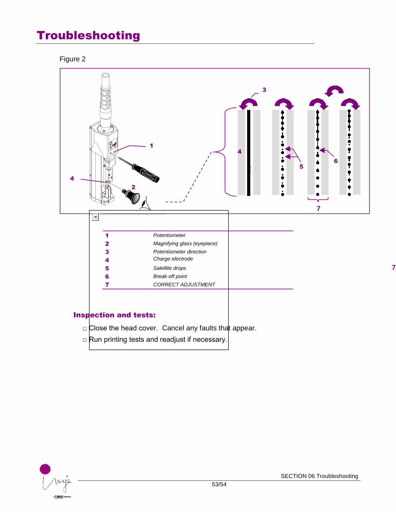
To adjust the break-off point, look at the jet opposite the charge electrode (stroboscopic LED) through the eyepiece (see Figure 2)
□ Start by turning the potentiometer to the left until it stops. The jet is not modulated.
□ Slowly turn to the right until the jet break-off point is in the center of the charge electrode. The shape should be similar to the one illustrated in Figure 2 (Correct adjustment).
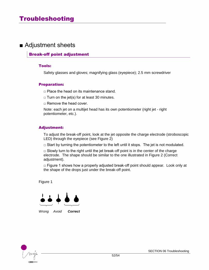
□ Figure 1 shows how a properly adjusted break-off point should appear. Look only at the shape of the drops just under the break-off point.
Figure 1
Wrong Avoid Correct
Troubleshooting
SECTION 06 Troubleshooting
53/54
Figure 2
1 Potentiometer
2 Magnifying glass (eyepiece)
3 Potentiometer direction
4 Charge electrode
5 Satellite drops
6 Break-off point
7 CORRECT ADJUSTMENT
Inspection and tests:
□ Close the head cover. Cancel any faults that appear.
□ Run printing tests and readjust if necessary.
3
4
7
1
2
7
6
4
5
Troubleshooting
SECTION 06 Troubleshooting
54/54
Recovery gutter adjustment
Tools:
□ Safety glasses and gloves; 0.9 mm Allen wrench; gutter adjustment tool.
Preparation:
□ Place the head on its maintenance stand.
□ Confirm the Production / Maint / Jet maintenance / Adjust jet function.
□ Remove the head cover.
Adjustment:
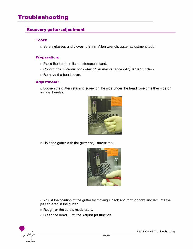
□ Loosen the gutter retaining screw on the side under the head (one on either side on twin-jet heads).
□ Hold the gutter with the gutter adjustment tool.
□ Adjust the position of the gutter by moving it back and forth or right and left until the jet centered in the gutter.
□ Retighten the screw moderately.
□ Clean the head. Exit the Adjust jet function.