Embed Size (px)
Citation preview
Solar Energy, Vol. lg, pp. 253-257. Pergamon Press 1976. Printed in Great Britain
END-CLEARANCE EFFECTS ON RECTANGULAR-HONEYCOMB SOLAR COLLECTORSt
D. K. EDWARDS, J. N. ARNOLD and I. CATrON Energy and Kinetics Department, School of Engineering and Applied Science UCLA, Los Angeles, CA 90024,
U.S.A.
(Received 28 July 1975; in revised form 18 February 1976)
Abstract--Results are reported of an experimental program to measure the effects of gaps between a honeycomb core and its coverglass and absorber plate. Nusselt numbers up to values of 2 vs Rayleigh number are reported for gaps of 0, 1.5, 2.3, 3.0 and 4.6 mm above and 0 and 1.5 mm below a 19 mm thick honeycomb core with 4.69 × 40.3 mm rectangular cells. The nontranspired honeycomb system was heated from below and oriented at 0 °, 15 o and 30 ° from the horizontal with the long dimension of the cells running horizontally. The results indicate that a well-designed honeycomb core will give good performance in a solar collector even with clearance gaps of 1.5 mm above and/or below the core.
INTRODUCTION
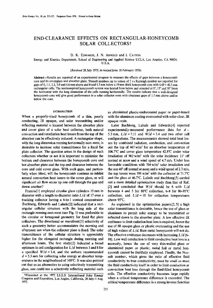
When a properly-sized honeycomb of a thin, poorly conducting, IR opaque, and solar transmitting and/or reflecting material is located between the absorber plate and cover glass of a solar heat collector, both natural convection and reradiation heat losses from the top of the absorber can be effectively reduced. A rectangular shape, with the long dimension running horizontally east-west, is desirable to increase solar transmittance for a fixed flat plate collector. The question arises in the design of such collectors whether or not it is important to minimize the bottom end clearance between the honeycomb core and hot absorber plate and the top end clearance between the core and cold cover glass. With such gaps, and particu- larly when tilted, will the honeycomb continue to inhibit natural convection heat losses to the cover glass, or will significant air flow occur up one cell through the gap and down another?
Francia[1] employed circular glass cylinders 15 mm in diameter with a length-to-diameter ratio L/d of 17 over a tracking collector having a 6-to-1 conical concentrator. Buchberg, Edwards and Lalude [2] indicated that a rect- angular cellular structure with the long side of the rectangle running east-west (see Fig. 1) was preferable to the circular or hexagonal geometry for fixed flat plate collectors. The directional or wavefront[3] selectivity of such a geometry better accommodates the morning and afternoon sun when the collector plate is fixed. The solar transmittance of the cellular structure is appreciably higher for the elongated rectangle during morning and afternoon hours. The first study/2] indicated a broad optimum in cell configuration for L/d between 3 and 8 for a specified W/d = 3.4, and the authors recommended d = 5.3 mm for collecting solar energy at absorber temp- eratures in the neighborhood of 100°C. It was also pointed out that as an alternative to using selectively transmitting glass, one could use a selectively reflecting material such
tPresented at the 1975 I.S.E.S. International Solar Energy Congress and Exposition, Los Angles, California, 28 July-1 Aug. 1975.
as aluminized plastic-undercoated paper or paper-board with the aluminum coating overcoated with solar-clear, IR opaque resin.
Later Buchberg, Lalude and Edwards/4] reported experimentally-measured performance data for d = 5.3mm, L/d =7.11 and W/d =3.4 and two other cell configurations. The measurements showed total heat los- ses by combined radiation, conduction, and convection out the top of 467 w/m 2 for an absorber temperature of 106.7°C and cover glass temperature 42.8°C under solar irradiation of 962w/m 2 with the solar incidence 11 ° off normal at noon and a wind speed of 4.7 m/s. Under less favorable conditions with 704 w/m 2 solar irradiation and the sun 46 o off normal at noon and a wind speed of 2.3 m/s, the top losses were 391 w/m 2 with the collector at 71.7°C and the glass at 46.7°C. Lalude and Buchberg[5] carried out a more detailed optimization study than that of Ref. [2] and concluded that W/d should be 6 with L/d between 4 and 5 for 8&C collection, 6-8 for 80-95°C collection, and L/d = 10 for collection temperatures above 95°C.
As explained in the optimization papers/2, 5] a high solar transmittance is desirable, hence the use of glass or aluminum to permit solar energy to be transmitted or reflected down to the absorber plate. A low effective IR emittance to limit radiation heat loss is required, hence the use of IR opaque glass or plastic overcoating and the use of high values of L/d. Bare metal honeycomb will not do. The effective emittance decreases with increasing L/d [6-- 10]. Low wall conduction to limit conductive heat loss is a necessity, hence the use of very thin-walled glass or aluminized paper or plastic; metal foil or metal hon- eycomb cannot be fruitfully employed. Finally, the Nus- selt number, which gives the ratio of effective fluid conductivity to true conductivity, must be small as must the fluid conductivity itself in order to limit conduction or convection heat loss through the fluid-filled honeycomb cells. The effective conductivity becomes large rapidly when a critical temperature difference is exceeded. The critical temperature difference is a strong inverse function
253
254 D. K. EDWARDS et al.
TOe
ABSORBER/ ~ ' ~ ~ GLASS
HONEYCOMB/ " ~
NORTH '~ SIDE VIEW
Fig. 1. Rectangular honeycomb dimensions.
of cell dimension d, hence the use of small values of d. The relationship of AT to d is through the Rayleigh
number
Rad (g COS z)/3(AT/L )d 4Pr v2 (1)
where g is gravity, z is angle of tilt of the absorber from the horizontal below position, /3 is volume expansion coefficient (equal to the reciprocal of absolute tempera- ture T for gases), AT is temperature difference between absorber plate and cover glass, L is the distance between absorber plate and cover glass, d the small dimension of the honeycomb, v kinematic viscosity of the fluid, and Pr the fluid's Prandtl number, the ratio of kinematic viscosity to thermal diffusivity.
In honeycomb cells over a tilted solar collector, warm light air underlies colder heavier air. Due to the tilt the lighter warm air does creep up the upper W × L side of the cell while the heavier cold air creeps down the bottom W × L side in essentially a two-dimensional motion. The two-dimensional creeping motion occurs for all AT grea- ter than zero. But this creeping motion is so feeble that it is of no practical consequence. What is of consequence to the solar collector designer is a cellular convection in which hot fluid rises in one half of the W × d cross section and falls in the other half. This form of convection arises only when Ra exceeds a critical value, as shown by Ostroumov [11] and Yih [12] for the infinite circular cylin- der, Ostrach and Pnueli[13] for the infinite arbitrary cylin- der with perfectly conducting side walls, Wooding [ 14] for the slot with adiabatic side walls, Edwards [15] for the slot with arbitrarily conducting side walls, Catton and Edwards[16] for the circular cylinder with arbitrary height and adiabatic or conducting side walls, Sun and Edwards [17] for the circular cylinder with arbitrary height and arbitrarily conducting side walls, and Edwards and Sun[18] for the rectangular cylinder with arbitrary height and arbitrarily conducting side walls. Edwards and Sun[18, 19] also showed a contribution of cell wall radia-
tion in raising critical Rayleigh number. Hollands[20] reported that a thin-walled honeycomb tested in air gave experimental values of critical Rayleigh number between the theoretical values appropriate to a perfectly insulating wall and a perfectly conducting wall, thus supporting the idea of a wall radiation effect.
The fact that a critical Rayleigh number exists, depend- ing upon L/d, W/d, and the wall conduction and radiation properties, indicates according to eqn (I) that a critical cell size d cannot be exceeded for a given AT/L and Lid without incurring the penalty of significant natural con- vection heat losses. Buchberg, Catton and Edwards[21] presented a graph of d vs AT[L and parameter Lid. For example, with Lid = 6, W/d = 6 and AT/L = 25°C/cm, d must be less than 5 ram. The strong increase in Nusselt number with increase in Rayleigh number past the critical value explains, for example, why Charters and Peterson[22] obtained poor performance with d = 25.4 ram.
In view of the sensitive dependence of critical tempera- ture difference upon honeycomb cell size, the question of the effect of gaps naturally arises. The present authors found nothing in the literature which shed light upon what influence gaps might have. Superficial thinking suggested that with gaps a given cell might be entirely filled with upflowing hot fluid while another might be filled with downflowing cold fluid with a resultant high convective heat transfer, less viscous dissipation, and less lateral conduction and cell wall radiation, all of which favor a lower critical Rayleigh number. Thus it was felt that end clearance gaps, which might have to be provided for thermal expansion, for example, should be investigated experimentally for their effect upon natural convection in honeycomb solar collectors.
APPARATUS AND PROCEDURE
Figure 2 shows a schematic of the apparatus employed. It is essentially that of Sun and Edwards[17, 18] and can be used with liquid or gas test fluids. Gasketed seals were
End-clearance effects on rectangular-honeycomb solar collectors
ANGLE INDICATOR -ALLEN- HEAD SET SCREW /-COILED SPRING
/ / /DIAPHRAGM RUBBER ,/ / /GASKETS I~ / / ,HOLD-DOWN PLATE
~ SUPPORT PLATE
~ B A K E L I T E BLOCK
_ I I ~ ~ ~ BRASS BLOCK I ~ ' 1 ~ - - COPPER PLATE
Jl~:~J ~ ~PHENOLIC - CLOTH ~ ~ J ~ - I ~ INSULATION
"~ )N'1~ \COPPER FACE ~I,,~ PLATE
L~ ~ "~ I \ " H E A T I N G / C O O L I N G "-, \ b, \ GUARD
\ \ IX "POLYURETHANE X X J] X WALL
"CLAMP PLATE
~, "CLAMP SLEEVE "STAINLESS STEEL SHAFT
Fig. 2. Experimental apparatus.
added to the ends of the apparatus to permit tilt to any desired angle [23].
Identical heat meter assemblies 125 x 152mm were made of a 0.76 mm thick copper face plate separated by a phenolic-filled cloth thermal resistor 1.42 mm thick from a 6mm copper base plate. Chromel-constantan ther- mocouples attached to the face plate and base plate are used to measure the temperature difference across the phenolic. The heat flux is proportional to the measured temperature difference. A 19 mm thick brass block with internal passages is in metal-to-metal contact with each 6 mm copper base plate. Circulating pumps cause hot water to warm one heat meter assembly while cold water cools the other. In this way heat is made to flow through the hot-face heat meter, into and through the test fluid enclosed between them, and out through the cold-face heat meter. The test fluid between the heat meters is contained laterally by 22 mm thick walls of polyurethane foam which are guard heated and cooled on the exterior opposite each 25 mm brass and copper exchanger-base- plate combination.
The honeycomb consisted of multiple cells, with d = 4.69 mm by W = 40.3 mm in cross section and L = 19 mm long. The walls were varnished paperboard 0.35 mm thick. A spacer on the bottom & in thickness was used, and the top spacing & was varied by moving the top heat meter away from the top edges of the honeycomb. The total distance between heat meters was thus L + & + &.
Calibration was made by heating from above in the horizontal position, 0 = 0, in the angular notation adopted. Then runs were made with 0 = 180 °, 165 ° and 150 °, that is, with the heated plate below and tilted ~ = 0 °, 15 ° and 30 ° from horizontal.
The ratio of the heat flow in the heated-from-below position to that in the heated-from-above position is the Nusselt number
Nu =keer= q(L + & + &,) k k A T (2)
where q is the convective-conductive heat flux, k is the
255
thermal conductivity of the fluid, and AT is the tempera- ture difference between the two copper face plates enclos- ing the fluid. Minor corrections were made in the com- puterized data reduction program for wall conduction and departures from strict steady state operation.
Nusselt number was determined from the data as a function of Rayleigh number based upon total length
Ra - g/3AT(L + 8, + ~b ) 3 KV
(3)
where g is gravitational acceleration,/3 volume expansion coefficient, K is thermal diffusivity (thermal conductivity divided by density-specific-heat product) and v is kinema- tic viscosity. The equations of motion indicate that Nus- selt number should be a function of Rayleigh number when inertial effects in the flow are negligible, and a function of Rayleigh and Prandtl number v/K when they are not, subject to the assumptions of constant transport properties. For Nusselt numbers close to unity, i.e. for small fluid velocities, inertial effects are small. Conse- quently, any fluid can be used for experimental purposes. In order to suppress thermal radiation as an independent heat transfer mechanism, silicone oils were chosen. In an IR-opaque fluid thermal radiation is merely one of the microscopic mechanisms which manifest themselves in the macroscopic world as thermal conduction.
RESULTS AND DISCUSSION
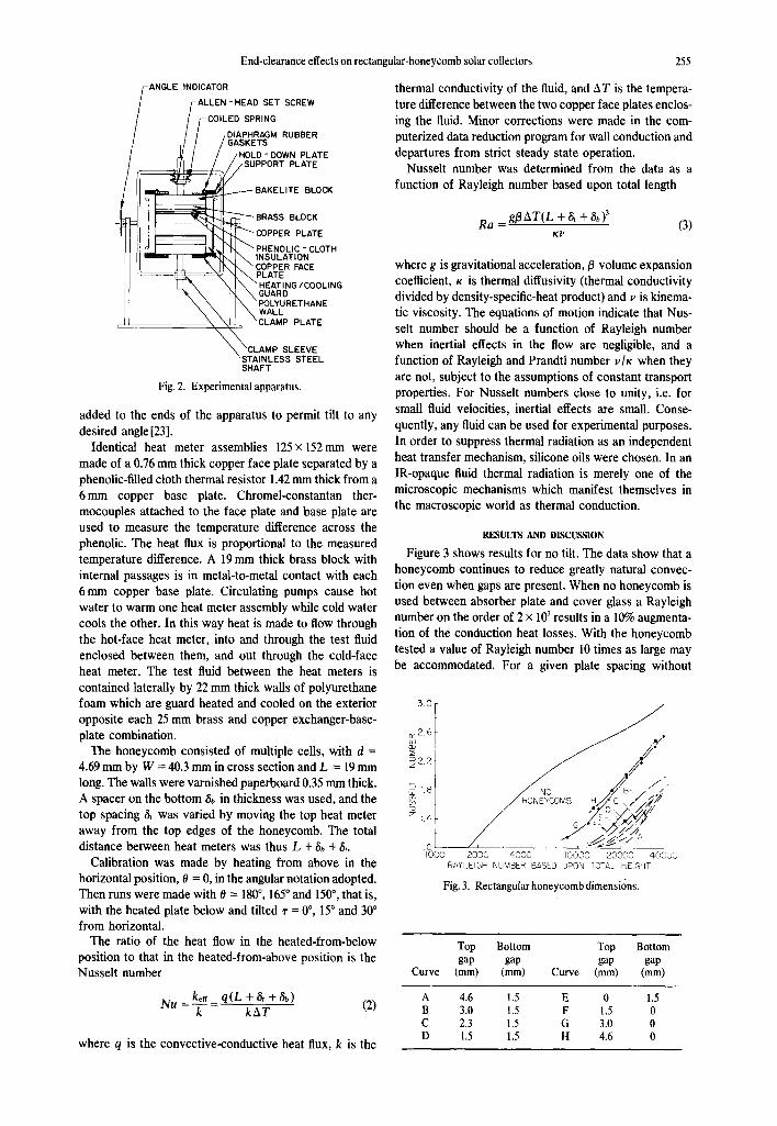
Figure 3 shows results for no tilt. The data show that a honeycomb continues to reduce greatly natural convec- tion even when gaps are present. When no honeycomb is used between absorber plate and cover glass a Rayleigh number on the order of 2 x 10 3 results in a 10% augmenta- tion of the conduction heat losses. With the honeycomb tested a value of Rayleigh number 10 times as large may be accommodated. For a given plate spacing without
3.0
0::2.6
2,2.2
~1.8
1.4
1.0 I000
J .,//' No #B- ~_#
/ 2ooo 4000 Ioo0o 20000 40o00
RAYLEIGH NUMBER BASED UPON TOTAL HEGHT
Fig. 3. Rectangular honeycomb dimensions.
Curve
Top Bottom Top Bottom gap gap gap gap
(mm) (ram) Curve (mm) (mm)
A 4.6 1.5 E 0 1.5 B 3.0 1.5 F 1.5 0 C 2.3 1.5 G 3.0 0 D 1.5 1.5 H 4.6 0
256 D. K. EDWARDS et al.
honeycomb a AT of only 10°C may cause significant convection, while with honeycomb a AT of 100°C would be required. However, the presence of a top gap of 3 mm or more does result in a marked decrease in Rayleigh number for a given Nusselt number. An unexpected result is that a small bottom gap of 1.5 mm is beneficial in that reasonably large top gaps may then be tolerated.
The surprising result that bottom gaps counteract top gaps suggests that the gaps permit an intercellular natural circulation which interferes with an intracellular natural convection. Due to the fact that the east-west length W is much larger than the north-south dimension d the intra- cellular convection would tend to be east-west oriented, while the intercellular convection is north-south oriented, that is, up the heated face and down the cooled one. The north-south through-the-cell convection permitted by a bottom gap in conjunction with a top gap evidently extends the damping effect of the honeycomb into the top gap region above the honeycomb.
Comparison of the present results in Fig. 3 with previ- ous results can be made only for the previous results with no gaps; to the authors' knowledge no other work has been performed on the effect of gaps. Previous work is of two kinds, prediction of critical Rayleigh number and measurement of the Nusselt-number-Rayleigh-number re- lationship after initiation. Catton theoretically predicted that for a rectangular cell of the present size convection should initiate at a critical Rayleigh number of 11,600 [24]. In a second work allowing for finite wall conduction this figure was revised to 11,800125]. Edwards and Sun[18] in an approximate analysis had predicted a value of 15,500 and had measured one of 13,000. The curves for small gaps C, D, E and F in Fig. 3 are seen to rise from a Nusselt number of unity at values of Rayleigh number in agreement with these previous findings. Data from Sun[26] for Nu vs Ra also agree favorably with curves D and E in Fig. 3 lending further support as shown in the short table below:
Nu Ra
Sun [26] Present work no gaps Curve D Curve E
1.1 17,000 16,500 14,500 1.25 20,500 21,000 18,500 1.50 27,000 28,000 26,000 1.75 36,000 36,000 36,000
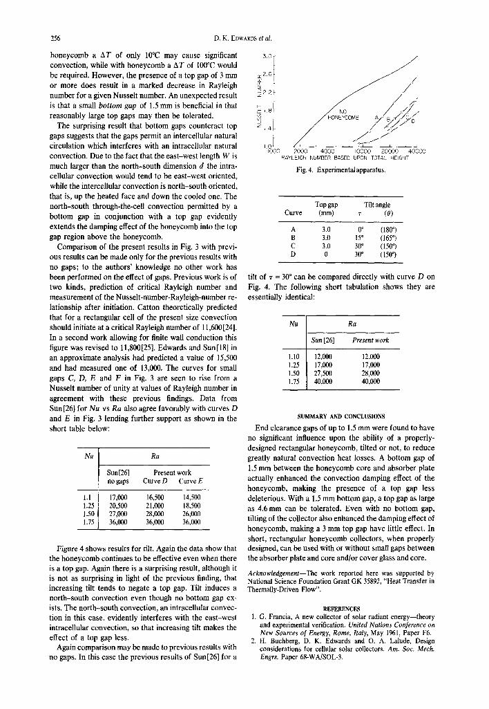
Figure 4 shows results for tilt. Again the data show that the honeycomb continues to be effective even when there is a top gap. Again there is a surprising result, although it is not as surprising in light of the previous finding, that increasing tilt tends to negate a top gap. Tilt induces a north-south convection even though no bottom gap ex- ists. The north-south convection, an intracellular convec- tion in this case, evidently interferes with the east-west intracellular convection, so that increasing tilt makes the effect of a top gap less.
Again comparison may be made to previous results with no gaps. In this case the previous results of Sun [26] for a
3.0 ~r ~-fi.6
/ . . . . . . . . . . . Z, (f -'°
,.o / . . . . . : X > 4000 2000 4000 I0000 20000 40000
RAYLEIGH NUMBER BASED UPON TOTAL HEIGHT
Fig. 4. Experimental apparatus.
Top gap Tilt angle Curve (mm) ~" (0)
A 3.0 0 ° (180 ° ) B 3.0 15 ° (165 ° ) C 3.0 30 ° (150 o ) D 0 30 ° (150 o )
tilt of ~" = 30 ° can be compared directly with curve D on Fig. 4. The following short tabulation shows they are essentially identical:
Nu Ra
Sun [26] Present work
1.10 12,000 12,000 1.25 17,000 17,000 1.50 27,500 28,000 1.75 40,000 40,000
SUMMARY AND CONCLUSIONS
End clearance gaps of up to 1.5 mm were found to have no significant influence upon the ability of a properly- designed rectangular honeycomb, tilted or not, to reduce greatly natural convection heat losses. A bottom gap of 1.5 mm between the honeycomb core and absorber plate actually enhanced the convection damping effect of the honeycomb, making the presence of a top gap less deleterious. With a 1.5 mm bottom gap, a top gap as large as 4.6 mm can be tolerated. Even with no bottom gap, tilting of the collector also enhanced the damping effect of honeycomb, making a 3 mm top gap have little effect. In short, rectangular honeycomb collectors, when properly designed, can be used with or without small gaps between the absorber plate and core and/or cover glass and core.
Acknowledgement--The work reported here was supported by National Science Foundation Grant GK 35892, "Heat Transfer in Thermally-Driven Flow".
REFERENCES 1. G. Francia, A new collector of solar radiant energy--theory
and experimental verification. United Nations Conference on New Sources o[ Energy, Rome, Italy, May 1961, Paper F6.
2. H. Buchberg, D. K. Edwards and O. A. Lalude, Design considerations for cellular solar collectors. Am. Soc. Mech. Engrs. Paper 68-WA/SOL-3.
End-clearance effects on rectangular-honeycomb solar collectors 257
3. H. Tabor, Selective radiation--I. Wavelength discrimination--II. Wavefront discrimination. Trans of the Conf. on the Use of Solar Energy, The Scientific Basis, Tucson, Arizona, 31 Oct.-1Nov. 1955, Vol. II, Chap. 2. Thermal Processes, Part 1, Section A, Flat Plate Collectors, pp. 1-39. Univ. of Arizona Press (1955).
4. H. Buchberg, O. A. Lalude and D. K. Edwards, Performance characteristics of rectangular honeycomb solar-thermal con- verters. Solar Energy 13, 193-221 (1971).
5. O. A. Lalude and H. Buchberg, Design of honeycomb porous bed solar air heaters. Solar Energy 13, 223-242 (1971).
6. H. C. Hottel and J. D. Keller, Effect of reradiation on heat transmission in furnaces and through openings. Trans. ASME 55, 39-49 (1933).
7. E. M. Sparrow, Radiant emission, absorption and transmis- sion characteristics of cavities and passages. Symposium on Thermal Radiation of Solids (Edited by S. Katzoff). NASA SP-55, pp. 103-116 (1964).
8. D. K. Edwards and R. D. Tobin, Effect of polarization on radiant heat transfer through long passages. J. Heat Transfer 89, 132-138 (1967).
9. D. K. Edwards and I. V. Bertak, Imperfect reflections in thermal radiation transfer. Progr. Astronaut. Aeronaut. 24, 143-165 (1971).
10. R. C. Amar and D. K. Edwards, Reflection and transmission by rough-walled passages. Prog. Astronaut. Aeronaut. 31, 475-495 (1973).
11. G. A. Ostroumov, Free convection under conditions of the internal problem. NACA TM 1407 (1958).
12. C. S. Yih, Thermal stability of viscous fluids. Q. Appl. Math. 17, 25-42 (1959).
13. S. Ostrach and D. Pnueli, The thermal stability of completely confined fluids inside some particular configurations. J. Heat Transl. 85, 346-354 (1963).
14. R. A. Wooding, Instability of a viscous liquid of variable density in a vertical Hele-Shaw cell. J. Fluid Mechan. 7, 501-515 (1960).
15. D. K. Edwards, Suppression of cellular convection by lateral walls. J. Heat Trans[. 91, 145-150 (1969).
16. I. Catton and D. K. Edwards, Initiation of thermal convection in finite right circular cylinders. A.LCh.E.J. 16, 594-601 (1970).
17. W. M. Sun and D. K. Edwards, Natural convection in cells with finite conducting walls heated from below. Heat Transfer 1970, Proc. 4th Intern. Heat Transfer Conf. Versailles, France, Sept. 1970, Paper NC 2.3, Elsevier, Amsterdam.
18. D. K. Edwards and W. M. Sun, Prediction of the onset of natural convection in rectangular honeycomb structures. Paper 7/62, 1970 International Solar Energy Society Confer- ence, Australian and New Zealand Section of ISES, 191 Royal Parade, Parkville, Victoria 3052, Australia.
19. D. K. Edwards and W. M. Sun, Effect of wall radiation on thermal instability in a vertical cylinder. Int. J. Heat Mass Trans.[. 14, 15-18 (1971).
20. K. G. T. Hollands, Natural convection in horizontal thin- walled honeycomb panels. J. Heat Transl. 95,439 444 (1973).
21. H. Buchberg, I. Catton and D. K. Edwards, Natural convection in enclosed spaces: a review of application to solar energy. 3. Heat and Transf: 98, 182-188 (1976).
22. W. W. S. Charters and L. F. Peterson, Free convection suppression using honeycomb cellular materials. Solar Energy 13, 353-361 (1972).
23. J. N. Arnold, P. N. Bonaparte, I. Catton and D. K. Edwards, Experimental investigation of natural convection in a finite rectangular re#on inclined at various angles from 0 ° to 180 °. Proc. 1974 Heat Transfer and Fluid Mechanics Institute (Edited by L. R. Davis and R. E. Wilson), pp. 321-329. Stanford Univ. Press, Stanford (1974).
24. I. Catton, The effect of insulating vertical walls on the onset of motion in a fluid heated from below. Int. J. Heat Mass Transl. 15, 665-672 (1972).
25. I. Catton, Effect of wall conduction on the stability of a fluid in a rectangular region heated from below. J. Heat Transl. 94, 446-452 (1972).
26. W. M. Sun, Effect of arbitrary wall conduction and radiation on free convection in a cylinder. Ph.D. Dissertation, School of Engineering, University of California, Los Angeles (1970).
Resumen--Se informan los resultados de un programa experimental para medir el efecto del espaciado entre la covertura de vidrio y el cuerpo de los "nidos de abeja" y entre 6ste y la placa absorbente. Se muestran los valores del ntlmero de Nusselt menores a 2 en functi6n del mimero de Rayleigh para espacios de 0; 1,5; 2,3; 3,0 y 4,6 ram. hacia arriba y espacios de 0 y 1,5 ram. hacia ahajo, en un cuerpo de 19 mm. de espesor de "nidos de abeja" de c61ulas rectangulares de 4,69 mmx 40,3 ram. E1 sistema seco ha sido calentado desde abajo y orientado en un fingulo de 0 °, 15 ° y 30 ° respecto a la horizontal, coincidiendo con esta la cara mayor del rect,'ingulo de las celdas. Los resultados indican que un cuerpo de "nidos de abeja" bien disefiado puede dar un buen comportamiento a un colector solar atin con espaciados de 1,5 ram. par encima y/o per debajo del cuerpo.
R6sum6---On donne les r6sultats d'un programme exp6rimental destin6 ~ mesurer les effets d'espacement entre le coeur d'un nid d'abeilles, sa couverture et la plaque de l'absorbeur. Des nombres de Nusselt jusqu'a 2, en fonction du nomre de Rayleigh, sont rapport6s pour des espacements de 0, 1,5, 2,3, 3,0 et 4,6 mm au dessus, et 0, 1,5 mm au dessous, d'un nid d'abeilles de 19mm d'6paisseur, de celhles rectangulaires de 4,69 par 40,3 mm. Le syst6me a 6t6 chanff6 par dessous, et orient6/t 0 °, 15 °, 30 ° pgr rapport ~ l'horizontale, la grande dimensions de cellule se plaeant horizontalement. Les r6sultats montrente qu'un coeur de nid d'abeilles bien coneu donnera de bonnes performances dans un capteur solaire m6me avec des tol6rances d'espacement de 1,5 mm an dessus et/ou an dessous du coeur.