Embed Size (px)
Citation preview
Bulletin 177 Revised 9.30.14 End Suction-Close Coupled Pumps
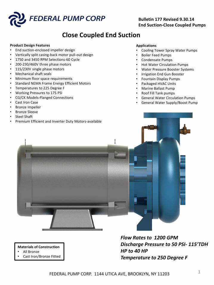
Close Coupled End Suction
Materials of Construction • All Bronze • Cast Iron/Bronze Fitted
FEDERAL PUMP CORP. 1144 UTICA AVE, BROOKLYN, NY 11203 1
Applications • Cooling Tower Spray Water Pumps • Boiler Feed Pumps • Condensate Pumps • Hot Water Circulation Pumps • Water Pressure Booster Systems • Irrigation End Gun Booster • Fountain Display Pumps • Packaged HVAC Units • Marine Ballast Pump • Roof Fill Tank pumps • General Water Circulation Pumps • General Water Supply/Boost Pump
Product Design Features • End suction-enclosed impeller design • Vertically split casing-back motor pull-out design • 1750 and 3450 RPM Selections-60 Cycle • 200-230/460V three phase motors • 115/230V single phase motors • Mechanical shaft seals • Minimum floor space requirements • Standard NEMA Frame Energy Efficient Motors • Temperatures to 225 Degree F • Working Pressures to 175 PSI • CG/CK Models-Flanged Connections • Cast Iron Case • Bronze Impeller • Bronze Sleeve • Steel Shaft • Premium Efficient and Inverter Duty Motors-available
Flow Rates to 1200 GPM Discharge Pressure to 50 PSI- 115’TDH HP to 40 HP Temperature to 250 Degree F
Bulletin 177 Revised 9.30.14 End Suction-Close Coupled Pumps
FEDERAL PUMP CORP. 1144 UTICA AVE, BROOKLYN, NY 11203 2
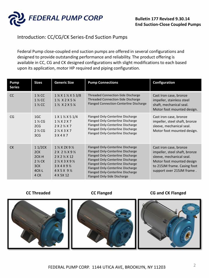
Introduction: CC/CG/CK Series-End Suction Pumps
Federal Pump close-coupled end suction pumps are offered in several configurations and designed to provide outstanding performance and reliability. The product offering is available in CC, CG and CK designed configurations with slight modifications to each based upon its application, motor HP required and piping configuration.
Pump Series
Sizes Generic Size Pump Connections Configuration
CC 1 ¼ CC 1 ½ CC 1 ½ CC
1 ¼ X 1 ½ X 5 3/8 1 ½ X 2 X 5 ¼ 1 ½ X 2 X 5 ¼
Threaded Connection-Side Discharge Threaded Connection-Side Discharge Flanged Connection-Centerline Discharge
Cast Iron case, bronze impeller, stainless steel shaft, mechanical seal. Motor foot mounted design.
CG 1GC 1 ½ CG 2CG 2 ½ CG 3CG
1 X 1 ½ X 5 1/4 1 ½ X 2 X 7 2 X 2 ½ X 7 2 ½ X 3 X 7 3 X 4 X 7
Flanged Only-Centerline Discharge Flanged Only-Centerline Discharge Flanged Only-Centerline Discharge Flanged Only-Centerline Discharge Flanged Only-Centerline Discharge
Cast iron case, bronze impeller, steel shaft, bronze sleeve, mechanical seal. Motor foot mounted design.
CK 1 1/2CK 2CK 2CK-H 2 ½ CK 3CK 4CK-L 4 CK
1 ½ X 2X 9 ½ 2 X 2 ½ X 9 ½ 2 X 2 ½ X 12 2 ½ X 3 X 9 ½ 3 X 4 X 9 ½ 4 X 5 X 9 ½ 4 X 5X 12
Flanged Only-Centerline Discharge Flanged Only-Centerline Discharge Flanged Only-Centerline Discharge Flanged Only-Centerline Discharge Flanged Only-Centerline Discharge Flanged Only-Centerline Discharge Flanged Only-Centerline Discharge Flanged Only-Side Discharge
Cast iron case, bronze impeller, steel shaft, bronze sleeve, mechanical seal. Motor foot mounted design to 215JM frame. Casing foot support over 215JM frame .
CC Threaded CC Flanged CG and CK Flanged
Bulletin 177 Revised 9.30.14 End Suction-Close Coupled Pumps
Horizontal Close-Coupled End Suction
FEDERAL PUMP CORP. 1144 UTICA AVE, BROOKLYN, NY 11203 3
Suggested Specifications
Furnish and install where shown in the plans and detailed on the equipment schedule, Federal Pump Series CC end suction close coupled pump(s) designed to deliver the rated flow in GPM at the rated Head in feet. Each pump shall include: Cast iron bronze fitted construction where casing shall be constructed of ASTM A48-Class 30 cast iron and tapped for pressure gauge and vent taps. Vent fitting will be of stainless steel construction threaded and connected by the pump manufacturer to the casing prior to shipment. Casing design will be back pull out type allowing the rotating assembly and motor to be disconnected from the casing without disturbing the connected piping. Impeller will be constructed of low lead bronze meeting the requirements of the Safe Drinking Water Act as amended 1.01.2014 and constructed of Grade C89833 single piece enclosed bronze casting machined and balanced by the pump manufacturer. Impeller will be threaded to the pump/motor shaft and secured in place with stainless steel impeller bolt and lock washer. Pump manufacturer will provide a mechanical seal mounted in the seal housing. Mechanical seal hall be rated for 125 PSI working pressure and suitable for temperatures to 250 degree F constructed of Buna elastomer, and provided with stainless steel springs, and ceramic and carbon seal faces. Motor shall be NEMA rated supplied and sized as shown in the equipment schedule, or as recommended by the pump manufacturer; of close coupled design where the pump casing is bolted directly to the motor and provided with 416 Stainless Steel shaft. Motor will be designed with ODP (Open Drip Proof) enclosure or as shown in the plans and provided with a 1.15 service factor and Class B Insulation. Single phase motors shall have built in overload protection. Motor voltage, phase and RPM shall be supplied as detailed in the plans or on the equipment schedule. Pump manufacturer will provide inverter duty motors where required for variable speed applications and meet the most recent NEMA requirements for energy efficient duty. Pump manufacturer will provide detailed motor information including full load amps, efficiency, power factor and wiring connections along with the pump submission. Close coupled pumps shall be warranted for a period of 12 months from date of shipment
Bulletin 177 Revised 9.30.14 End Suction-Close Coupled Pumps
Series CC, CG and CK Horizontal Close-Coupled End Suction
Performance Curves
FEDERAL PUMP CORP. 1144 UTICA AVE, BROOKLYN, NY 11203 4
3450 RPM
Bulletin 177 Revised 9.30.14 End Suction-Close Coupled Pumps
FEDERAL PUMP CORP. 1144 UTICA AVE, BROOKLYN, NY 11203 5
3450 RPM
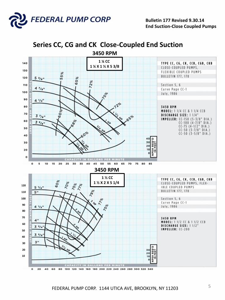
1 ¼ CC 1 ¼ X 1 ½ X 5 3/8
1 ½ CC 1 ½ X 2 X 5 1/4
10
20
30
40
50
60
70
80
90
100
110
120
Series CC, CG and CK Close-Coupled End Suction
3450 RPM
Bulletin 177 Revised 9.30.14 End Suction-Close Coupled Pumps
FEDERAL PUMP CORP. 1144 UTICA AVE, BROOKLYN, NY 11203 6
3450 RPM
3450 RPM
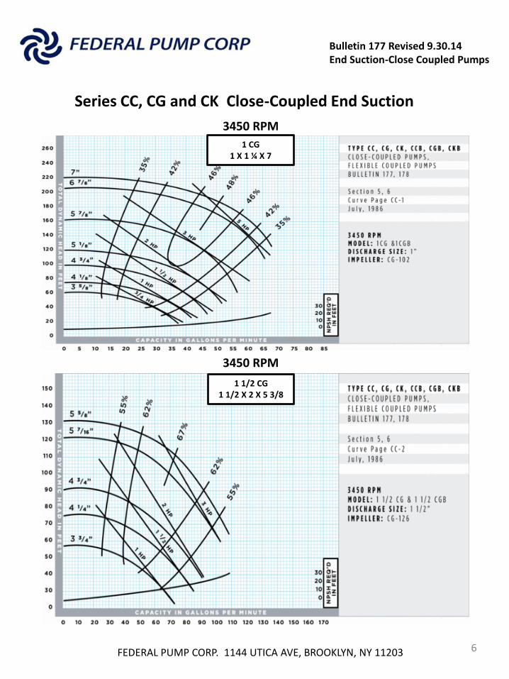
1 CG 1 X 1 ¼ X 7
1 1/2 CG 1 1/2 X 2 X 5 3/8
Series CC, CG and CK Close-Coupled End Suction
Bulletin 177 Revised 9.30.14 End Suction-Close Coupled Pumps
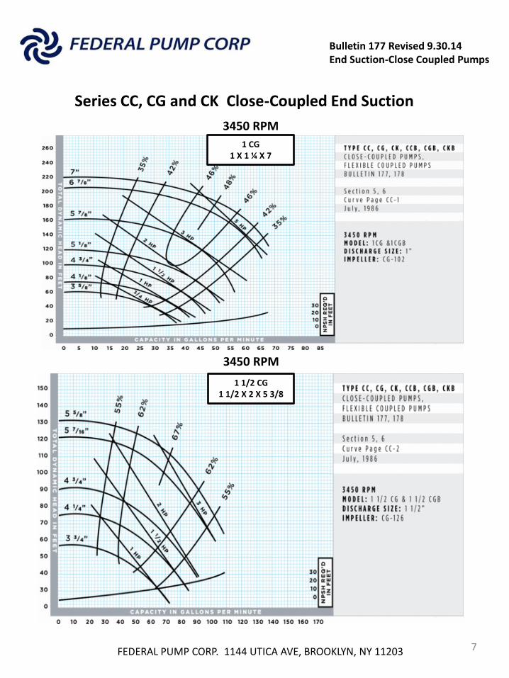
FEDERAL PUMP CORP. 1144 UTICA AVE, BROOKLYN, NY 11203 7
3450 RPM
3450 RPM
1 CG 1 X 1 ¼ X 7
1 1/2 CG 1 1/2 X 2 X 5 3/8
Series CC, CG and CK Close-Coupled End Suction
Bulletin 177 Revised 9.30.14 End Suction-Close Coupled Pumps
Series CC, CG and CK Close-Coupled End Suction
FEDERAL PUMP CORP. 1144 UTICA AVE, BROOKLYN, NY 11203 8
3450 RPM
3450 RPM
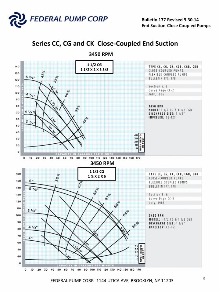
1 1/2 CG 1 1/2 X 2 X 5 3/8
1 1/2 CG 1 ½ X 2 X 6
Bulletin 177 Revised 9.30.14 End Suction-Close Coupled Pumps
FEDERAL PUMP CORP. 1144 UTICA AVE, BROOKLYN, NY 11203 9
3450 RPM
3450 RPM
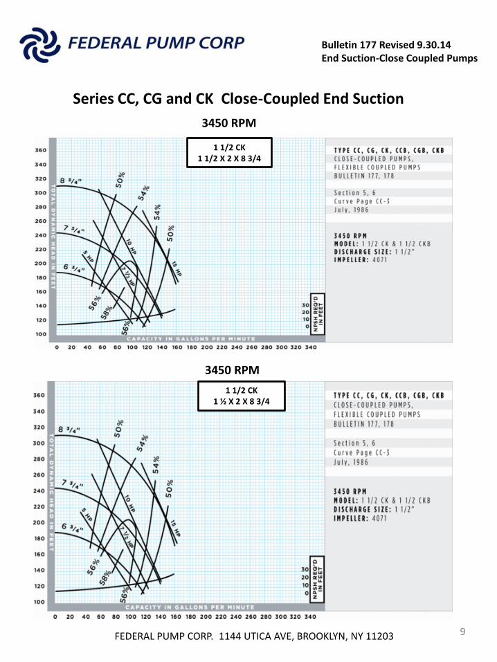
1 1/2 CK 1 1/2 X 2 X 8 3/4
1 1/2 CK 1 ½ X 2 X 8 3/4
Series CC, CG and CK Close-Coupled End Suction
Bulletin 177 Revised 9.30.14 End Suction-Close Coupled Pumps
FEDERAL PUMP CORP. 1144 UTICA AVE, BROOKLYN, NY 11203 10
3450 RPM
3450 RPM
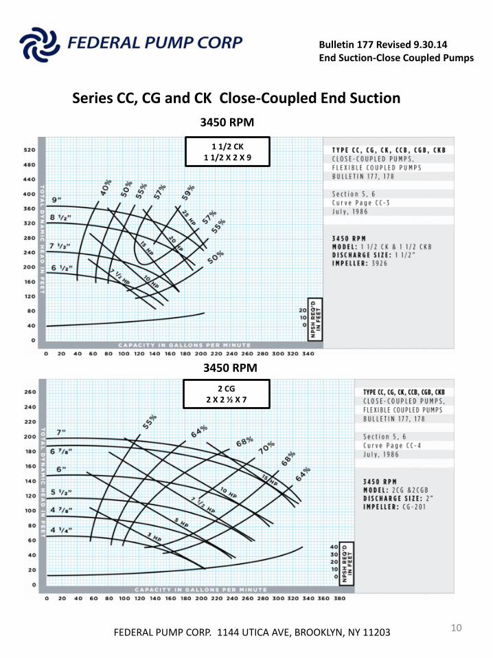
1 1/2 CK 1 1/2 X 2 X 9
2 CG 2 X 2 ½ X 7
Series CC, CG and CK Close-Coupled End Suction
Bulletin 177 Revised 9.30.14 End Suction-Close Coupled Pumps
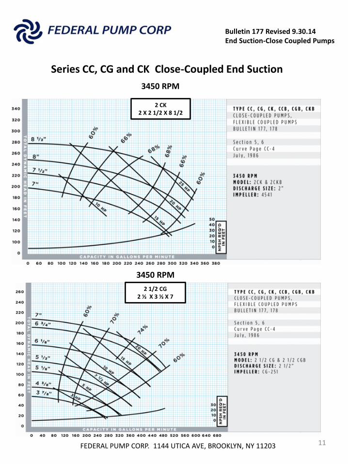
FEDERAL PUMP CORP. 1144 UTICA AVE, BROOKLYN, NY 11203 11
3450 RPM
3450 RPM
2 CK 2 X 2 1/2 X 8 1/2
2 1/2 CG 2 ½ X 3 ½ X 7
3450 RPM
Series CC, CG and CK Close-Coupled End Suction
Bulletin 177 Revised 9.30.14 End Suction-Close Coupled Pumps
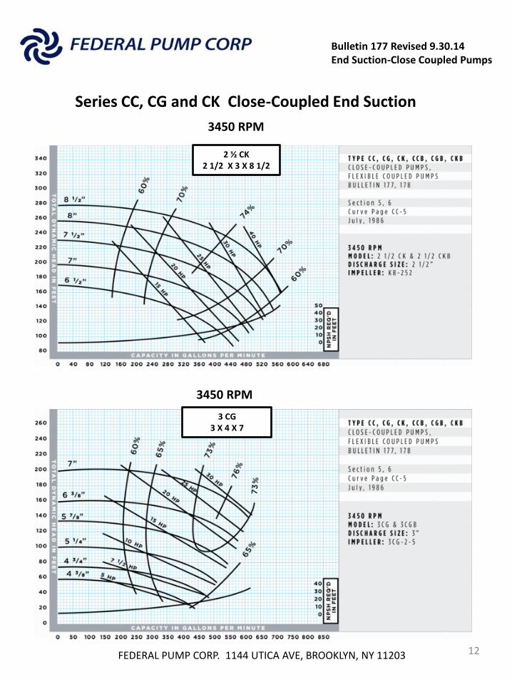
FEDERAL PUMP CORP. 1144 UTICA AVE, BROOKLYN, NY 11203 12
3450 RPM
3450 RPM
2 ½ CK 2 1/2 X 3 X 8 1/2
3 CG 3 X 4 X 7
Series CC, CG and CK Close-Coupled End Suction
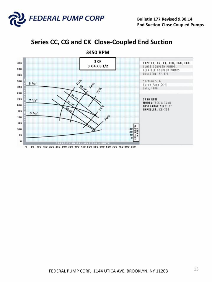
Bulletin 177 Revised 9.30.14 End Suction-Close Coupled Pumps
FEDERAL PUMP CORP. 1144 UTICA AVE, BROOKLYN, NY 11203 13
3450 RPM
3 CK 3 X 4 X 8 1/2
Series CC, CG and CK Close-Coupled End Suction
Bulletin 177 Revised 9.30.14 End Suction-Close Coupled Pumps
Series CC, CG and CK Horizontal Close-Coupled End Suction
Performance Curves
FEDERAL PUMP CORP. 1144 UTICA AVE, BROOKLYN, NY 11203 14
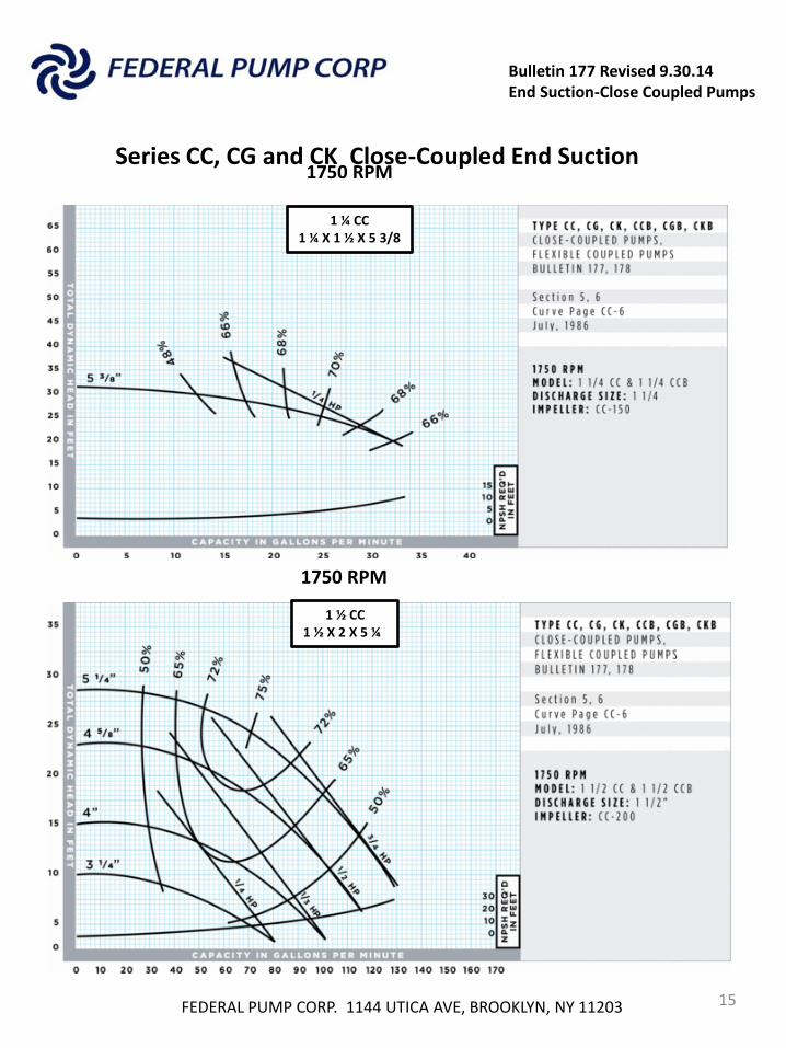
1750 RPM
Bulletin 177 Revised 9.30.14 End Suction-Close Coupled Pumps
FEDERAL PUMP CORP. 1144 UTICA AVE, BROOKLYN, NY 11203 15
1750 RPM
1 ¼ CC 1 ¼ X 1 ½ X 5 3/8
1 ½ CC 1 ½ X 2 X 5 ¼
1750 RPM
Series CC, CG and CK Close-Coupled End Suction
Bulletin 177 Revised 9.30.14 End Suction-Close Coupled Pumps
FEDERAL PUMP CORP. 1144 UTICA AVE, BROOKLYN, NY 11203 16
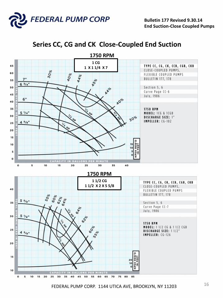
1750 RPM
1750 RPM
1 CG 1 X 1 1/4 X 7
1 1/2 CG 1 1/2 X 2 X 5 5/8
Series CC, CG and CK Close-Coupled End Suction
Bulletin 177 Revised 9.30.14 End Suction-Close Coupled Pumps
FEDERAL PUMP CORP. 1144 UTICA AVE, BROOKLYN, NY 11203 17
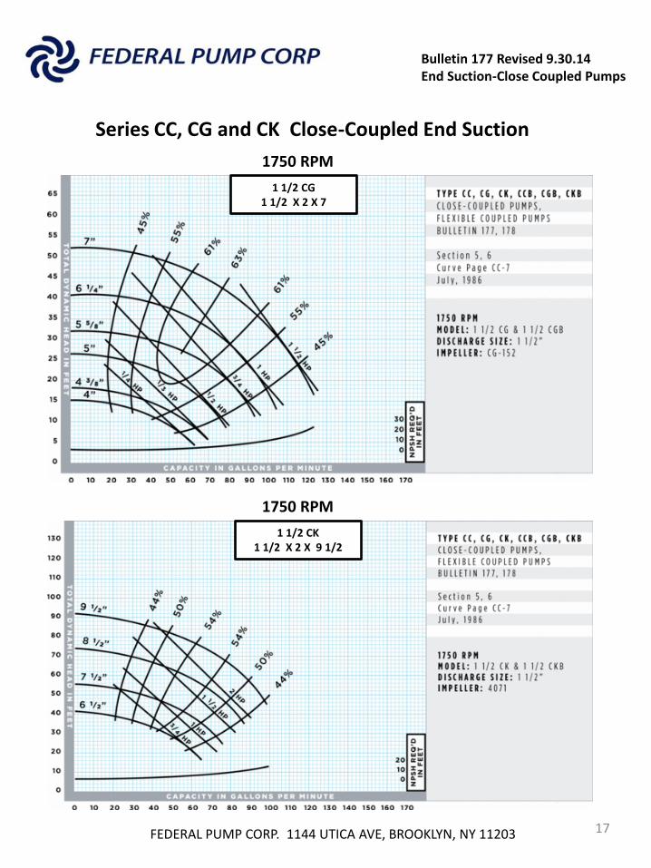
1750 RPM
1750 RPM
1 1/2 CG 1 1/2 X 2 X 7
1 1/2 CK 1 1/2 X 2 X 9 1/2
Series CC, CG and CK Close-Coupled End Suction
Bulletin 177 Revised 9.30.14 End Suction-Close Coupled Pumps
FEDERAL PUMP CORP. 1144 UTICA AVE, BROOKLYN, NY 11203 18
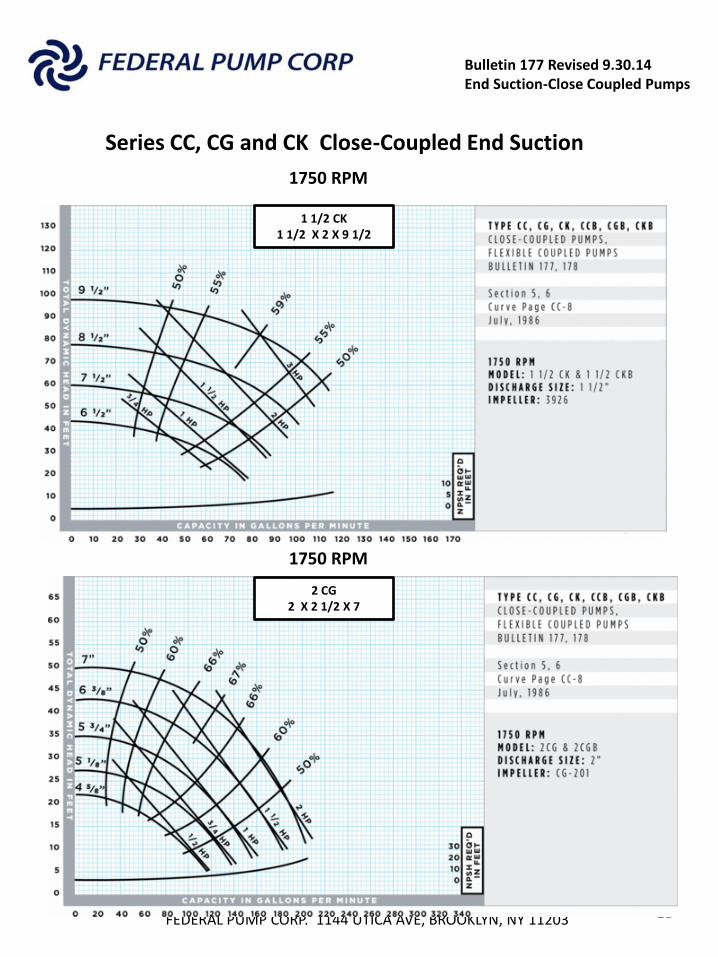
1750 RPM
1750 RPM
1 1/2 CK 1 1/2 X 2 X 9 1/2
2 CG 2 X 2 1/2 X 7
Series CC, CG and CK Close-Coupled End Suction
Bulletin 177 Revised 9.30.14 End Suction-Close Coupled Pumps
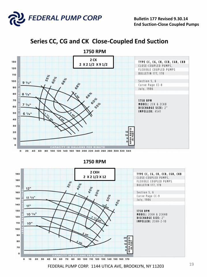
FEDERAL PUMP CORP. 1144 UTICA AVE, BROOKLYN, NY 11203 19
1750 RPM
1750 RPM
2 CK 2 X 2 1/2 X 9 1/2
2 CKH 2 X 2 1/2 X 12
Series CC, CG and CK Close-Coupled End Suction
Bulletin 177 Revised 9.30.14 End Suction-Close Coupled Pumps
FEDERAL PUMP CORP. 1144 UTICA AVE, BROOKLYN, NY 11203 20
1750 RPM
1750 RPM
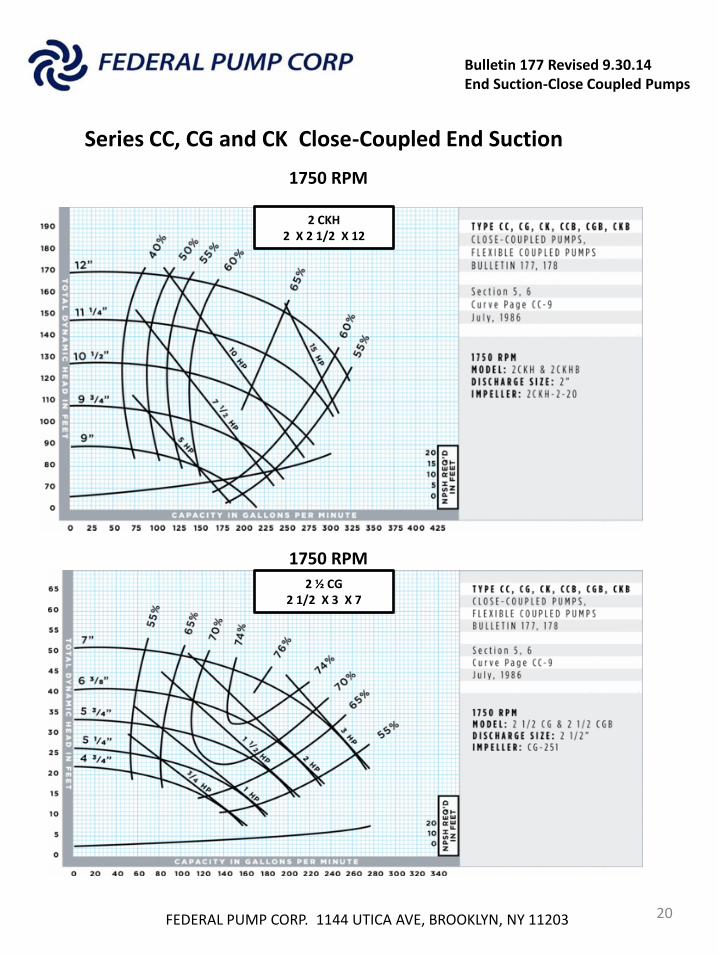
2 CKH 2 X 2 1/2 X 12
2 ½ CG 2 1/2 X 3 X 7
Series CC, CG and CK Close-Coupled End Suction
Bulletin 177 Revised 9.30.14 End Suction-Close Coupled Pumps
FEDERAL PUMP CORP. 1144 UTICA AVE, BROOKLYN, NY 11203 21
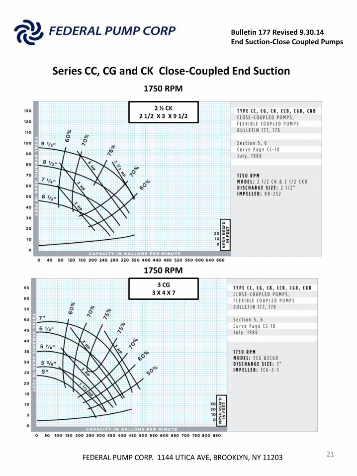
1750 RPM
1750 RPM
2 ½ CK 2 1/2 X 3 X 9 1/2
3 CG 3 X 4 X 7
Series CC, CG and CK Close-Coupled End Suction
Bulletin 177 Revised 9.30.14 End Suction-Close Coupled Pumps
FEDERAL PUMP CORP. 1144 UTICA AVE, BROOKLYN, NY 11203 22
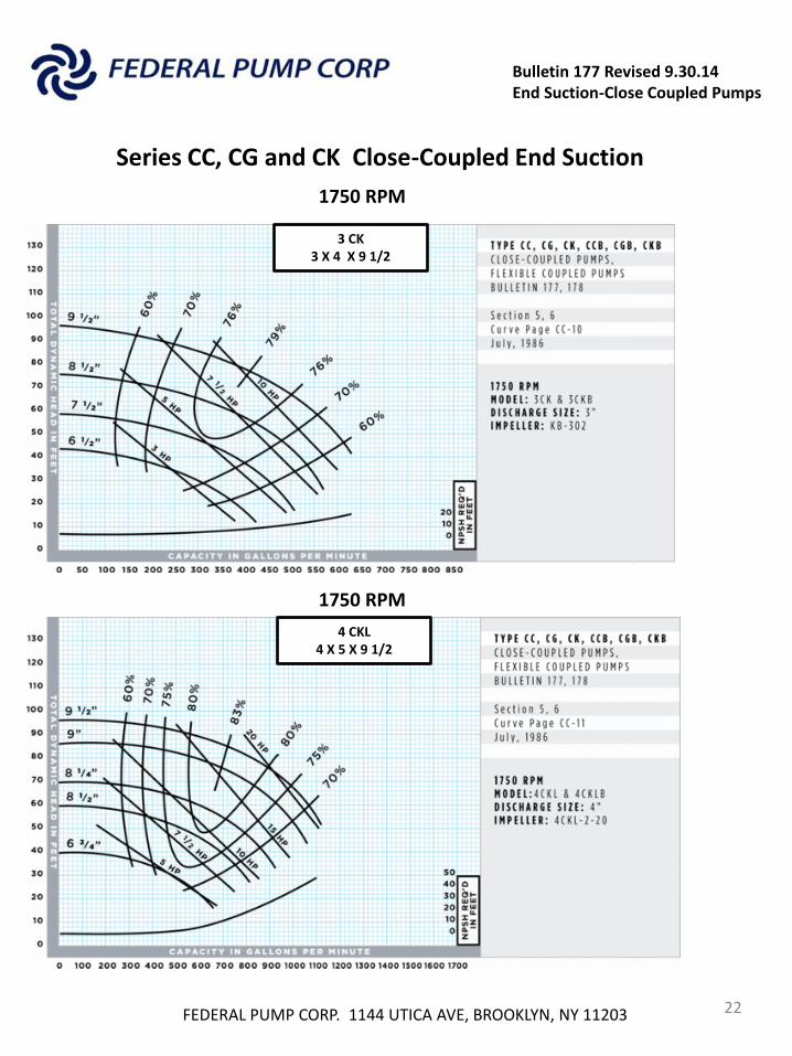
1750 RPM
1750 RPM
3 CK 3 X 4 X 9 1/2
4 CKL 4 X 5 X 9 1/2
Series CC, CG and CK Close-Coupled End Suction
Bulletin 177 Revised 9.30.14 End Suction-Close Coupled Pumps
FEDERAL PUMP CORP. 1144 UTICA AVE, BROOKLYN, NY 11203 23
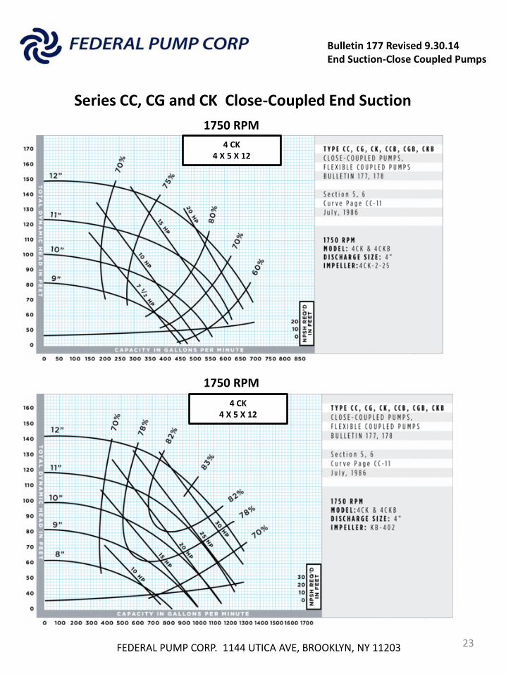
1750 RPM
1750 RPM
4 CK 4 X 5 X 12
4 CK 4 X 5 X 12
Series CC, CG and CK Close-Coupled End Suction
Bulletin 177 Revised 9.30.14 End Suction-Close Coupled Pumps
Horizontal Close-Coupled End Suction
FEDERAL PUMP CORP. 1144 UTICA AVE, BROOKLYN, NY 11203 24
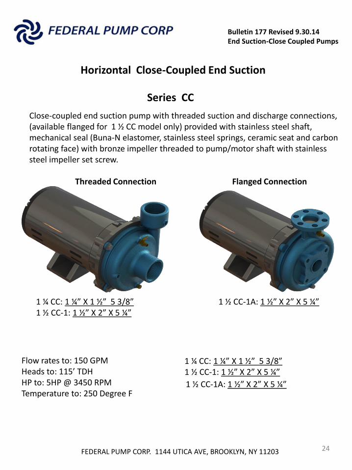
Series CC
Close-coupled end suction pump with threaded suction and discharge connections, (available flanged for 1 ½ CC model only) provided with stainless steel shaft, mechanical seal (Buna-N elastomer, stainless steel springs, ceramic seat and carbon rotating face) with bronze impeller threaded to pump/motor shaft with stainless steel impeller set screw.
Flow rates to: 150 GPM Heads to: 115’ TDH HP to: 5HP @ 3450 RPM Temperature to: 250 Degree F
1 ¼ CC: 1 ¼” X 1 ½” 5 3/8” 1 ½ CC-1: 1 ½” X 2” X 5 ¼”
1 ¼ CC: 1 ¼” X 1 ½” 5 3/8” 1 ½ CC-1: 1 ½” X 2” X 5 ¼”
1 ½ CC-1A: 1 ½” X 2” X 5 ¼”
Threaded Connection Flanged Connection
1 ½ CC-1A: 1 ½” X 2” X 5 ¼”
Bulletin 177 Revised 9.30.14 End Suction-Close Coupled Pumps
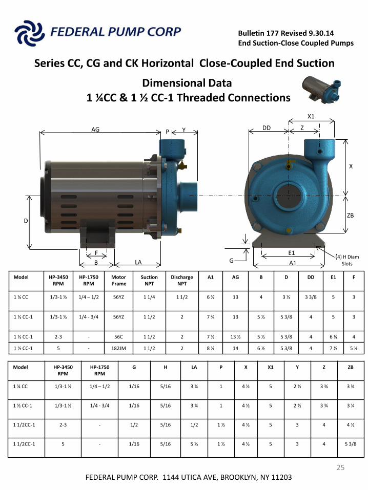
Series CC, CG and CK Horizontal Close-Coupled End Suction
FEDERAL PUMP CORP. 1144 UTICA AVE, BROOKLYN, NY 11203 25
Dimensional Data 1 ¼CC & 1 ½ CC-1 Threaded Connections
Model HP-3450 RPM
HP-1750 RPM
Motor Frame
Suction NPT
Discharge NPT
A1 AG B D DD E1 F
1 ¼ CC 1/3-1 ½
1/4 – 1/2
56YZ 1 1/4 1 1/2 6 ½
13 4 3 ½
3 3/8 5 3
1 ½ CC-1 1/3-1 ½
1/4 - 3/4
56YZ 1 1/2 2 7 ¾ 13 5 ½
5 3/8
4 5 3
1 ½ CC-1 2-3 - 56C 1 1/2 2 7 ½ 13 ½ 5 ½ 5 3/8 4 6 ¼ 4
1 ½ CC-1 5 - 182JM 1 1/2 2 8 ½ 14 6 ½ 5 3/8 4 7 ½ 5 ½
Model HP-3450 RPM
HP-1750 RPM
G H LA P X X1 Y Z ZB
1 ¼ CC 1/3-1 ½
1/4 – 1/2 1/16
5/16 3 ¼
1 4 ½
5 2 ½ 3 ¾
3 ¾
1 ½ CC-1
1/3-1 ½ 1/4 - 3/4 1/16 5/16 3 ¼
1 4 ½
5 2 ½
3 ¾
3 ¼
1 1/2CC-1 2-3 - 1/2 5/16 1/2 1 ½
4 ½
5
3 4 4 ½
1 1/2CC-1 5 - 1/16 5/16 5 ½
1 ½
4 ½
5 3 4 5 3/8
A1
E1
X1
ZB
X
F
P
G
AG Y P
B (4) H Diam
Slots
F
LA
E1
DD Z
ZB
X
G
D
Bulletin 177 Revised 9.30.14 End Suction-Close Coupled Pumps
Series CC, CG and CK Horizontal Close-Coupled End Suction
FEDERAL PUMP CORP. 1144 UTICA AVE, BROOKLYN, NY 11203 26
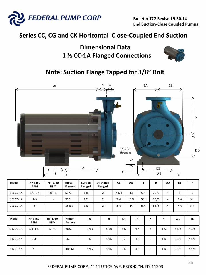
Dimensional Data 1 ½ CC-1A Flanged Connections
Note: Suction Flange Tapped for 3/8” Bolt
Model HP-3450 RPM
HP-1750 RPM
Motor Frames
Suction Flanged
Discharge Flanged
A1 AG B D DD E1 F
1 ½ CC-1A 1/3-1 ½ ¼ - ¾ 56YZ 1 ½ 2 7 3/4 13 5 ½ 5 3/8 4 5 3
1 ½ CC-1A 2-3 - 56C 1 ½ 2 7 ½ 13 ½ 5 ½ 5 3/8 4 7 ½ 5 ½
1 ½ CC-1A 5 - 182JM 1 ½ 2 8 ½ 14 6 ½ 5 3/8 4 7 ½ 5 ½
Model HP-3450 RPM
HP-1750 RPM
Motor Frames
G H LA P X Y ZA ZB
1 ½ CC-1A 1/3 -1 ½ ¼ - ¾ 56YZ 1/16 5/16 3 ¼
4 ½
6 1 ¾
3 3/8 4 1/8
1 ½ CC-1A 2-3 - 56C ½
5/16 ½
4 ½
6 1 ¾ 3 3/8
4 1/8
1 ½ CC-1A 5 - 182JM 1/16 5/16
5 ½ 4 ½ 6
1 ¾
3 3/8 4 1/8
AG
P ZB ZA
D
A1 B
E1
DD
X
(4) 3/8”
Threaded
Y AG
F LA G
27
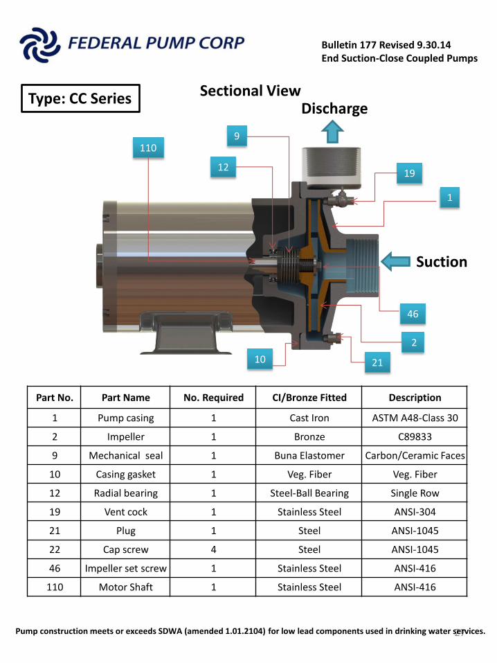
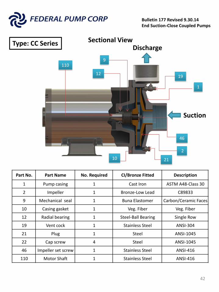
Part No. Part Name No. Required CI/Bronze Fitted Description
1 Pump casing 1 Cast Iron ASTM A48-Class 30
2 Impeller 1 Bronze C89833
9 Mechanical seal 1 Buna Elastomer Carbon/Ceramic Faces
10 Casing gasket 1 Veg. Fiber Veg. Fiber
12 Radial bearing 1 Steel-Ball Bearing Single Row
19 Vent cock 1 Stainless Steel ANSI-304
21 Plug 1 Steel ANSI-1045
22 Cap screw 4 Steel ANSI-1045
46 Impeller set screw 1 Stainless Steel ANSI-416
110 Motor Shaft 1 Stainless Steel ANSI-416
1
2
9
10
19
46
110
21
Type: CC Series
Suction
Discharge
12
Pump construction meets or exceeds SDWA (amended 1.01.2104) for low lead components used in drinking water services.
Bulletin 177 Revised 9.30.14 End Suction-Close Coupled Pumps
Sectional View
Bulletin 177 Revised 9.30.14 End Suction-Close Coupled Pumps
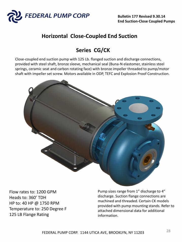
Horizontal Close-Coupled End Suction
FEDERAL PUMP CORP. 1144 UTICA AVE, BROOKLYN, NY 11203 28
Series CG/CK
Close-coupled end suction pump with 125 Lb. flanged suction and discharge connections, provided with steel shaft, bronze sleeve, mechanical seal (Buna-N elastomer, stainless steel springs, ceramic seat and carbon rotating face) with bronze impeller threaded to pump/motor shaft with impeller set screw. Motors available in ODP, TEFC and Explosion Proof Construction.
Flow rates to: 1200 GPM Heads to: 360’ TDH HP to: 40 HP @ 1750 RPM Temperature to: 250 Degree F 125 LB Flange Rating
Pump sizes range from 1” discharge to 4” discharge. Suction flange connections are machined and threaded. Certain CK models provided with pump mounting stands. Refer to attached dimensional data for additional information.
Bulletin 177 Revised 9.30.14 End Suction-Close Coupled Pumps
Horizontal Close-Coupled End Suction
FEDERAL PUMP CORP. 1144 UTICA AVE, BROOKLYN, NY 11203 29
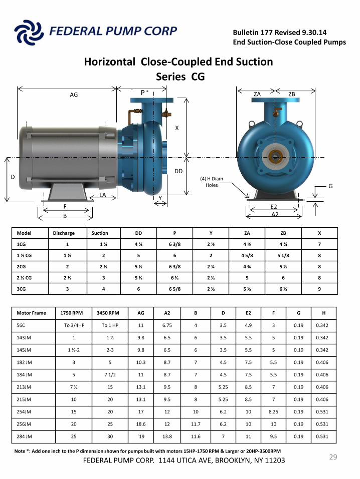
Series CG
Model Discharge Suction DD P Y ZA ZB X
1CG 1 1 ¼ 4 ¾ 6 3/8 2 ½ 4 ½ 4 ¾ 7
1 ½ CG 1 ½ 2 5 6 2 4 5/8 5 1/8 8
2CG 2 2 ½ 5 ½ 6 3/8 2 ¼ 4 ¾ 5 ½ 8
2 ½ CG 2 ½ 3 5 ½ 6 ½ 2 ½ 5 6 8
3CG 3 4 6 6 5/8 2 ½ 5 ½ 6 ½ 9
P
Y
B
F
D
A2
E2
G
Motor Frame 1750 RPM 3450 RPM AG A2 B D E2 F G H
56C To 3/4HP To 1 HP 11 6.75 4 3.5 4.9 3 0.19 0.342
143JM 1 1 ½ 9.8 6.5 6 3.5 5.5 5 0.19 0.342
145JM 1 ½-2 2-3 9.8 6.5 6 3.5 5.5 5 0.19 0.342
182 JM 3 5 10.3 8.7 7 4.5 7.5 5.5 0.19 0.406
184 JM 5 7 1/2 11 8.7 7 4.5 7.5 5.5 0.19 0.406
213JM 7 ½ 15 13.1 9.5 8 5.25 8.5 7 0.19 0.406
215JM 10 20 13.1 9.5 8 5.25 8.5 7 0.19 0.406
254JM 15 20 17 12 10 6.2 10 8.25 0.19 0.531
256JM 20 25 18.6 12 11.7 6.2 10 10 0.19 0.531
284 JM 25 30 `19 13.8 11.6 7 11 9.5 0.19 0.531
DD
X
AG P
F
LA Y
E2
Note *: Add one inch to the P dimension shown for pumps built with motors 15HP-1750 RPM & Larger or 20HP-3500RPM
* ZA ZB
(4) H Diam Holes

Bulletin 177 Revised 9.30.14 End Suction-Close Coupled Pumps
Horizontal Close-Coupled End Suction
FEDERAL PUMP CORP. 1144 UTICA AVE, BROOKLYN, NY 11203 30
Series CK Thru 182 JM Motors
Model Discharge Suction DD P Y ZA ZB A1 E1 X L H1 G
1 ½ CK 1 ½ 2 6 5/8 6 ¼ 2 ¼ 6 6 ½ 12 10.5 10 5 3/16 3/4 1/2
2 CK 2 2 ½ 7 1/2 6 ½ 2 ¼ 6 3/8 7 12 10.5 10 5 ¼ 3/4 1/2
2 CKH 2 3 8 6 ½ 1 ½ 7 ¾ 7 ¾ 12 10.375 11 ½ 5 3/4 3/4 1/2
2 ½ CK 2 ½ 3 7 1/2 6 ½ 2 ¼ 6 5/8 6 5/8 12 10.5 10 ½ 5 5/16 3/4 1/2
3CK 3 4 7 1/4 7 ¼ 2 ¾ 6 ¾ 7 1/8 A2 E2 11 ------ ------ ------
4CKL 4 5 7 3/4 7 1/8 2 3/8 7 8 5/8 A2 E2 12 ------ ------ ------
AG P
DD
X
B
F
D
A1
G
Motor Frame 1750 RPM 3450 RPM AG B D F G H
56C To 3/4HP To 1 HP 11 4 3.5 3 0.19 0.34
143JM 1 1 ½ 9.8 6 3.5 5 0.19 0.34
145JM 1 ½-2 2-3 9.8 6 3.5 5 0.19 0.34
182 JM 3 5 10.3 7 4.5 5.5 0.19 0.41
L
**3CK & 4CKL do not use support bracket L
L**
F Y
** L Bracket
Note: For larger motors (184 JM to 324 JM Frames) “L” bracket is not included. Refer to attached dimensions for 184JM-324JM CK pump/motor dimensions
ZA ZB
E1
H1 Hole Diam.
Bulletin 177 Revised 9.30.14 End Suction-Close Coupled Pumps
Horizontal Close-Coupled End Suction
FEDERAL PUMP CORP. 1144 UTICA AVE, BROOKLYN, NY 11203 31
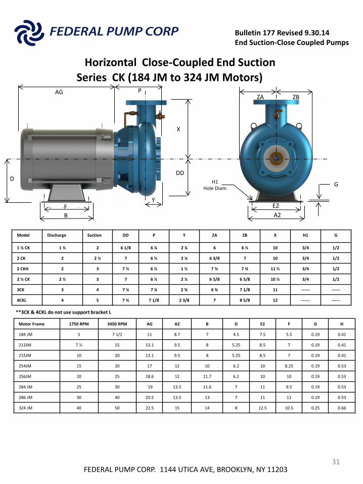
Series CK (184 JM to 324 JM Motors)
Model Discharge Suction DD P Y ZA ZB X H1 G
1 ½ CK 1 ½ 2 6 1/8 6 ¼ 2 ¼ 6 6 ½ 10 3/4 1/2
2 CK 2 2 ½ 7 6 ½ 2 ¼ 6 3/8 7 10 3/4 1/2
2 CKH 2 3 7 ½ 6 ½ 1 ½ 7 ¾ 7 ¾ 11 ½ 3/4 1/2
2 ½ CK 2 ½ 3 7 6 ½ 2 ¼ 6 5/8 6 5/8 10 ½ 3/4 1/2
3CK 3 4 7 ¼ 7 ¼ 2 ¾ 6 ¾ 7 1/8 11 ------ ------
4CKL 4 5 7 ¾ 7 1/8 2 3/8 7 8 5/8 12 ------ ------
AG P
DD
X
B
F
D
A2
G
Motor Frame 1750 RPM 3450 RPM AG A2 B D E2 F G H
184 JM 5 7 1/2 11 8.7 7 4.5 7.5 5.5 0.19 0.41
213JM 7 ½ 15 13.1 9.5 8 5.25 8.5 7 0.19 0.41
215JM 10 20 13.1 9.5 8 5.25 8.5 7 0.19 0.41
254JM 15 20 17 12 10 6.2 10 8.25 0.19 0.53
256JM 20 25 18.6 12 11.7 6.2 10 10 0.19 0.53
284 JM 25 30 `19 13.5 11.6 7 11 9.5 0.19 0.53
286 JM 30 40 20.5 13.5 13 7 11 11 0.19 0.53
324 JM 40 50 22.5 15 14 8 12.5 10.5 0.25 0.66
**3CK & 4CKL do not use support bracket L
L**
F Y
ZB ZA
E2
H1 Hole Diam.
Bulletin 177 Revised 9.30.14 End Suction-Close Coupled Pumps
Horizontal Close-Coupled End Suction
FEDERAL PUMP CORP. 1144 UTICA AVE, BROOKLYN, NY 11203 32
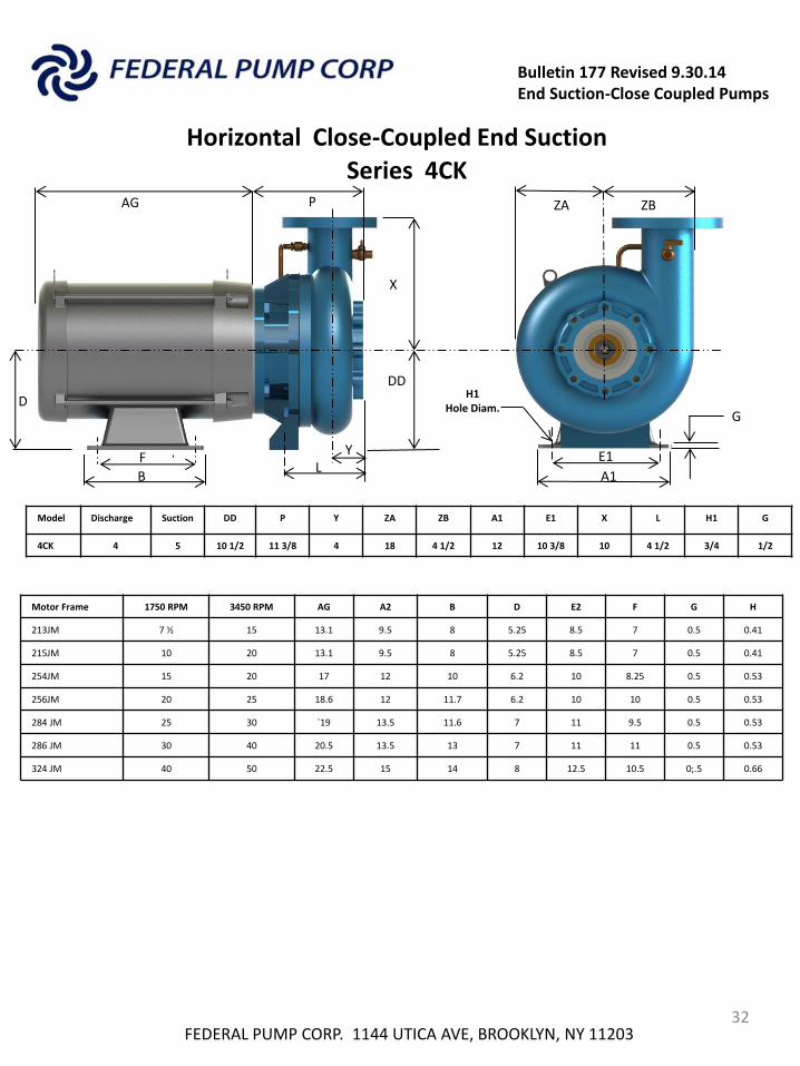
Series 4CK
Model Discharge Suction DD P Y ZA ZB A1 E1 X L H1 G
4CK 4 5 10 1/2 11 3/8 4 18 4 1/2 12 10 3/8 10 4 1/2 3/4 1/2
AG P
DD
X
B
D
A1
Motor Frame 1750 RPM 3450 RPM AG A2 B D E2 F G H
213JM 7 ½ 15 13.1 9.5 8 5.25 8.5 7 0.5 0.41
215JM 10 20 13.1 9.5 8 5.25 8.5 7 0.5 0.41
254JM 15 20 17 12 10 6.2 10 8.25 0.5 0.53
256JM 20 25 18.6 12 11.7 6.2 10 10 0.5 0.53
284 JM 25 30 `19 13.5 11.6 7 11 9.5 0.5 0.53
286 JM 30 40 20.5 13.5 13 7 11 11 0.5 0.53
324 JM 40 50 22.5 15 14 8 12.5 10.5 0;.5 0.66
L
G
ZA ZB
E1
H1 Hole Diam.
F Y
Bulletin 177 Revised 9.30.14 End Suction-Close Coupled Pumps
Horizontal Close-Coupled End Suction
FEDERAL PUMP CORP. 1144 UTICA AVE, BROOKLYN, NY 11203 33
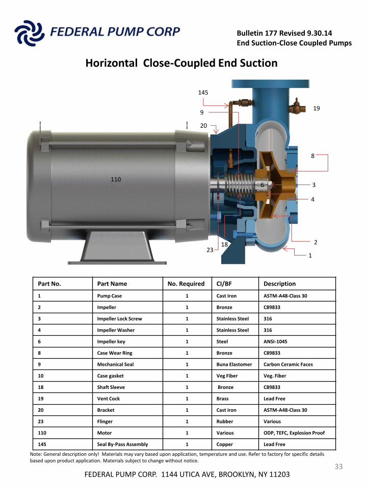
Sectional View
6
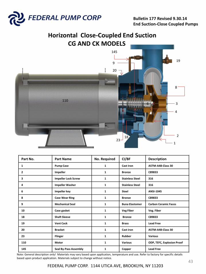
Part No. Part Name No. Required CI/BF Description
1 Pump Case 1 Cast Iron ASTM-A48-Class 30
2 Impeller 1 Bronze C89833
3 Impeller Lock Screw 1 Stainless Steel 316
4 Impeller Washer 1 Stainless Steel 316
6 Impeller key 1 Steel ANSI-1045
8 Case Wear Ring 1 Bronze C89833
9 Mechanical Seal 1 Buna Elastomer Carbon Ceramic Faces
10 Case gasket 1 Veg Fiber Veg. Fiber
18 Shaft Sleeve 1 Bronze C89833
19 Vent Cock 1 Brass Lead Free
20 Bracket 1 Cast iron ASTM-A48-Class 30
23 Flinger 1 Rubber Various
110 Motor 1 Various ODP, TEFC, Explosion Proof
145 Seal By-Pass Assembly 1 Copper Lead Free
2
1
3
4
8
9
18
19
6
110
Note: General description only! Materials may vary based upon application, temperature and use. Refer to factory for specific details based upon product application. Materials subject to change without notice.
23
20
145
110
Bulletin 177 Revised 9.30.14 End Suction-Close Coupled Pumps
Series CC, CG and CK Horizontal Close-Coupled End Suction
FEDERAL PUMP CORP. 1144 UTICA AVE, BROOKLYN, NY 11203 34
Series CC
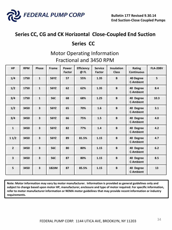
Motor Operating Information Fractional and 3450 RPM
HP RPM Phase Frame Power Factor
Efficiency @ FL
Service Factor
Insulation Class
Rating Continuous
FLA-208V
1/4 1750 1 56YZ 57 55% 1.35 B 40 Degree C-Ambient
5
1/2 1750 1 56YZ 62 62% 1.35 B 40 Degree C-Ambient
8.4
3/4 1750 1 56C 68 68% 1.25 B 40 Degree C-Ambient
10.3
1/2 3450 3 56YZ 65 70% 1.6 B 40 Degree C-Ambient
3.1
3/4 3450 3 56YZ 66 75% 1.5 B 40 Degree C-Ambient
4.0
1 3450 3 56YZ 82 77% 1.4 B 40 Degree C-Ambient
4.2
1 1/2 3450 3 56YZ 89 81.5% 1.15 B 40 Degree C-Ambient
4.7
2 3450 3 56C 80 80% 1.15 B 40 Degree C-Ambient
6.2
3 3450 3 56C 87 80% 1.15 B 40 Degree C-Ambient
8.5
5 3450 3 182JM 87 85.5% 1.15 B 40 Degree C-Ambient
13
Note: Motor information may vary by motor manufacturer. Information is provided as general guidelines only and subject to change based upon motor HP, manufacturer, enclosure and type of motor required. For specific information, refer to motor manufacturer information or NEMA motor guidelines that may provide recent information or industry requirements.
FEDERAL PUMP CORP. 1144 UTICA AVE, BROOKLYN, NY 11203 35
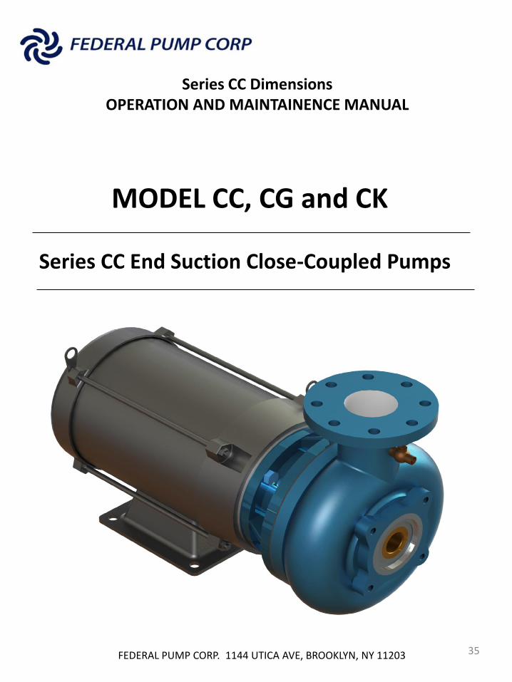
Series CC Dimensions OPERATION AND MAINTAINENCE MANUAL
Series CC End Suction Close-Coupled Pumps
MODEL CC, CG and CK
FEDERAL PUMP CORP. 1144 UTICA AVE, BROOKLYN, NY 11203 36
Series CC Dimensions OPERATION AND MAINTAINENCE MANUAL
Series CC End Suction Close-Coupled Pumps
MODEL CC, CG and CK
Item Page
Pump Identification 36
Receiving 37
Storing 37
Location 37
Installation 37
Pipe Connections 38
Water Supply 38
Priming the Pump 39
Start Up 39
Pump components –Type CC 40
Pump components –Type CG & CK 41
Note: Use only Factory authorized replacement parts to ensure proper operation of the installed Federal Pump. Use of unauthorized parts may cause for early pump failure and loss of warranty!
FEDERAL PUMP CORP. 1144 UTICA AVE, BROOKLYN, NY
11203 37
OPERATION AND MAINTAINENCE MANUAL
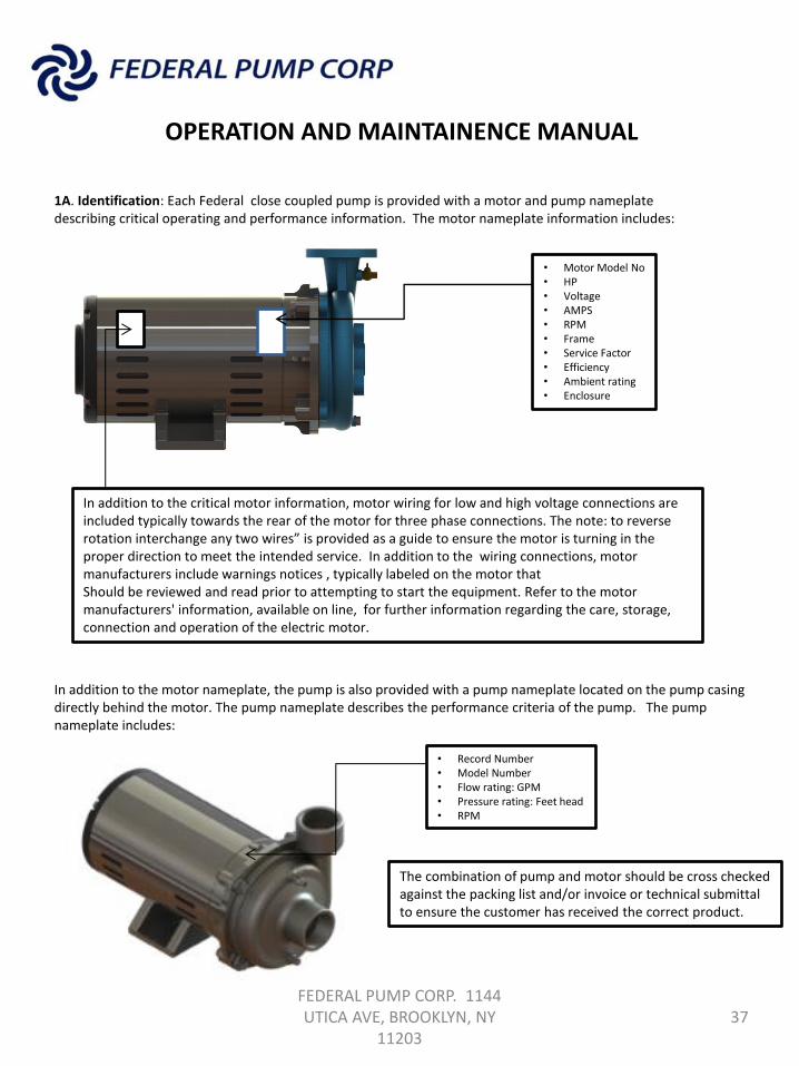
1A. Identification: Each Federal close coupled pump is provided with a motor and pump nameplate describing critical operating and performance information. The motor nameplate information includes:
• Motor Model No • HP • Voltage • AMPS • RPM • Frame • Service Factor • Efficiency • Ambient rating • Enclosure
In addition to the critical motor information, motor wiring for low and high voltage connections are included typically towards the rear of the motor for three phase connections. The note: to reverse rotation interchange any two wires” is provided as a guide to ensure the motor is turning in the proper direction to meet the intended service. In addition to the wiring connections, motor manufacturers include warnings notices , typically labeled on the motor that Should be reviewed and read prior to attempting to start the equipment. Refer to the motor manufacturers' information, available on line, for further information regarding the care, storage, connection and operation of the electric motor.
In addition to the motor nameplate, the pump is also provided with a pump nameplate located on the pump casing directly behind the motor. The pump nameplate describes the performance criteria of the pump. The pump nameplate includes: • Record Number
• Model Number • Flow rating: GPM • Pressure rating: Feet head • RPM
The combination of pump and motor should be cross checked against the packing list and/or invoice or technical submittal to ensure the customer has received the correct product.
FEDERAL PUMP CORP. 1144 UTICA AVE, BROOKLYN, NY
11203 38
OPERATION AND MAINTAINENCE MANUAL
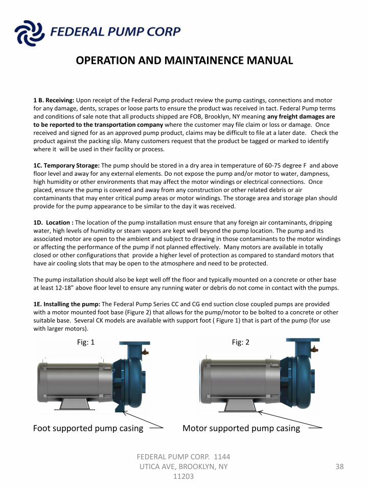
1 B. Receiving: Upon receipt of the Federal Pump product review the pump castings, connections and motor for any damage, dents, scrapes or loose parts to ensure the product was received in tact. Federal Pump terms and conditions of sale note that all products shipped are FOB, Brooklyn, NY meaning any freight damages are to be reported to the transportation company where the customer may file claim or loss or damage. Once received and signed for as an approved pump product, claims may be difficult to file at a later date. Check the product against the packing slip. Many customers request that the product be tagged or marked to identify where it will be used in their facility or process. 1C. Temporary Storage: The pump should be stored in a dry area in temperature of 60-75 degree F and above floor level and away for any external elements. Do not expose the pump and/or motor to water, dampness, high humidity or other environments that may affect the motor windings or electrical connections. Once placed, ensure the pump is covered and away from any construction or other related debris or air contaminants that may enter critical pump areas or motor windings. The storage area and storage plan should provide for the pump appearance to be similar to the day it was received. 1D. Location : The location of the pump installation must ensure that any foreign air contaminants, dripping water, high levels of humidity or steam vapors are kept well beyond the pump location. The pump and its associated motor are open to the ambient and subject to drawing in those contaminants to the motor windings or affecting the performance of the pump if not planned effectively. Many motors are available in totally closed or other configurations that provide a higher level of protection as compared to standard motors that have air cooling slots that may be open to the atmosphere and need to be protected. The pump installation should also be kept well off the floor and typically mounted on a concrete or other base at least 12-18” above floor level to ensure any running water or debris do not come in contact with the pumps. 1E. Installing the pump: The Federal Pump Series CC and CG end suction close coupled pumps are provided with a motor mounted foot base (Figure 2) that allows for the pump/motor to be bolted to a concrete or other suitable base. Several CK models are available with support foot ( Figure 1) that is part of the pump (for use with larger motors).
Foot supported pump casing Motor supported pump casing
Fig: 1 Fig: 2
FEDERAL PUMP CORP. 1144 UTICA AVE, BROOKLYN, NY
11203 39
OPERATION AND MAINTAINENCE MANUAL
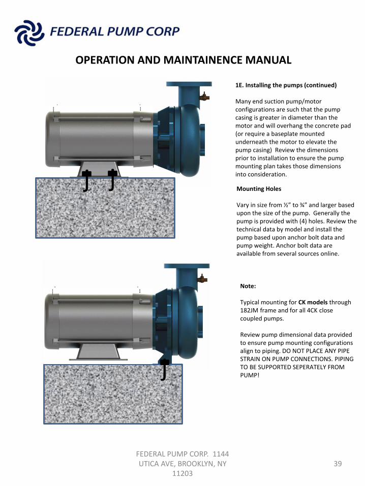
Mounting Holes Vary in size from ½” to ¾” and larger based upon the size of the pump. Generally the pump is provided with (4) holes. Review the technical data by model and install the pump based upon anchor bolt data and pump weight. Anchor bolt data are available from several sources online.
1E. Installing the pumps (continued) Many end suction pump/motor configurations are such that the pump casing is greater in diameter than the motor and will overhang the concrete pad (or require a baseplate mounted underneath the motor to elevate the pump casing) Review the dimensions prior to installation to ensure the pump mounting plan takes those dimensions into consideration.
j j
j
Note: Typical mounting for CK models through 182JM frame and for all 4CK close coupled pumps. Review pump dimensional data provided to ensure pump mounting configurations align to piping. DO NOT PLACE ANY PIPE STRAIN ON PUMP CONNECTIONS. PIPING TO BE SUPPORTED SEPERATELY FROM PUMP!
j j
FEDERAL PUMP CORP. 1144 UTICA AVE, BROOKLYN, NY
11203 40
OPERATION AND MAINTAINENCE MANUAL
Mounting Holes Vary in size from ½” to ¾” and larger based upon the size of the pump. Generally the pump is provided with (4) holes. Review the technical data by model and install the pump based upon anchor bolt data and pump weight. Anchor bolt data are available from several sources online.
1E. Installing the pumps (continued) Many end suction pump/motor configurations are such that the pump casing is greater in diameter than the motor and will overhang the concrete pad (or require a baseplate mounted underneath the motor to elevate the pump casing) Review the dimensions prior to installation to ensure the pump mounting plan takes those dimensions into consideration.
1F. Pipe connections: Federal Pump series CC is available with either threaded connections or flanged connections and generally outlined in technical data received prior to product shipment. In either case, pipe connections to the pump must be supported separately where the pump should not be used as a support structure for the piping. ENSURE THERE IS NO PIPE STRAIN ON THE PUMP CASING! In addition to avoiding pipe strain, the pipe sizes and connections to the pump should always be greater that the pump suction and discharge connections and not less. Where possible and practical each pump should be provided with its own suction and discharge isolation (or shut-off) valve, as close to the pump as possible, and discharge check valve as close to the pump discharge connection as possible. 1G. Water Supply : Each Federal Pump has been designed to operate over a range of varying flow conditions and requires sufficient inlet pressure to the pump to operate effectively. If the inlet pressure is insufficient, the pump may experience cavitation where it would vibrate excessively and operate in a noisy manner. If the water supply is not sufficient due to improper piping sizing or lack of available suction pressure the cavitation or vibration will reduce the pump life significantly and may cause irreversible damage to the pump. IF AFTER THE INSTALLTION THE CUSTOMER EXPERIENCES CAVITATION, CONTACT YOUR NEAREST FEDERAL PUMP SALES REPRESENTAIVE FOR A WATER SUPPLY SYSTEM REVIEW.
FEDERAL PUMP CORP. 1144 UTICA AVE, BROOKLYN, NY
11203 41
OPERATION AND MAINTAINENCE MANUAL
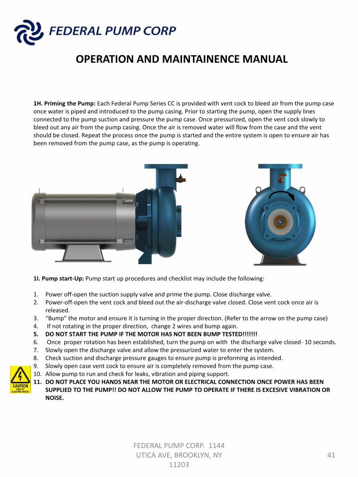
1H. Priming the Pump: Each Federal Pump Series CC is provided with vent cock to bleed air from the pump case once water is piped and introduced to the pump casing. Prior to starting the pump, open the supply lines connected to the pump suction and pressure the pump case. Once pressurized, open the vent cock slowly to bleed out any air from the pump casing. Once the air is removed water will flow from the case and the vent should be closed. Repeat the process once the pump is started and the entire system is open to ensure air has been removed from the pump case, as the pump is operating. 1I. Pump start-Up: Pump start up procedures and checklist may include the following: 1. Power off-open the suction supply valve and prime the pump. Close discharge valve. 2. Power-off-open the vent cock and bleed out the air-discharge valve closed. Close vent cock once air is
released. 3. “Bump” the motor and ensure it is turning in the proper direction. (Refer to the arrow on the pump case) 4. If not rotating in the proper direction, change 2 wires and bump again. 5. DO NOT START THE PUMP IF THE MOTOR HAS NOT BEEN BUMP TESTED!!!!!!! 6. Once proper rotation has been established, turn the pump on with the discharge valve closed- 10 seconds. 7. Slowly open the discharge valve and allow the pressurized water to enter the system. 8. Check suction and discharge pressure gauges to ensure pump is preforming as intended. 9. Slowly open case vent cock to ensure air is completely removed from the pump case. 10. Allow pump to run and check for leaks, vibration and piping support. 11. DO NOT PLACE YOU HANDS NEAR THE MOTOR OR ELECTRICAL CONNECTION ONCE POWER HAS BEEN
SUPPLIED TO THE PUMP!! DO NOT ALLOW THE PUMP TO OPERATE IF THERE IS EXCESIVE VIBRATION OR NOISE.
42
Part No. Part Name No. Required CI/Bronze Fitted Description
1 Pump casing 1 Cast Iron ASTM A48-Class 30
2 Impeller 1 Bronze-Low Lead C89833
9 Mechanical seal 1 Buna Elastomer Carbon/Ceramic Faces
10 Casing gasket 1 Veg. Fiber Veg. Fiber
12 Radial bearing 1 Steel-Ball Bearing Single Row
19 Vent cock 1 Stainless Steel ANSI-304
21 Plug 1 Steel ANSI-1045
22 Cap screw 4 Steel ANSI-1045
46 Impeller set screw 1 Stainless Steel ANSI-416
110 Motor Shaft 1 Stainless Steel ANSI-416
1
2
9
10
19
46
110
21
Type: CC Series
Suction
Discharge
12
Bulletin 177 Revised 9.30.14 End Suction-Close Coupled Pumps
Sectional View
Bulletin 177 Revised 9.30.14 End Suction-Close Coupled Pumps
Horizontal Close-Coupled End Suction Cg AND ck
FEDERAL PUMP CORP. 1144 UTICA AVE, BROOKLYN, NY 11203 43
Sectional View
6
Part No. Part Name No. Required CI/BF Description
1 Pump Case 1 Cast Iron ASTM-A48-Class 30
2 Impeller 1 Bronze C89833
3 Impeller Lock Screw 1 Stainless Steel 316
4 Impeller Washer 1 Stainless Steel 316
6 Impeller key 1 Steel ANSI-1045
8 Case Wear Ring 1 Bronze C89833
9 Mechanical Seal 1 Buna Elastomer Carbon Ceramic Faces
10 Case gasket 1 Veg Fiber Veg. Fiber
18 Shaft Sleeve 1 Bronze C89833
19 Vent Cock 1 Brass Lead Free
20 Bracket 1 Cast iron ASTM-A48-Class 30
23 Flinger 1 Rubber Various
110 Motor 1 Various ODP, TEFC, Explosion Proof
145 Seal By-Pass Assembly 1 Copper Lead Free
2
1
3
4
8
9
18
19
6
110
Note: General description only! Materials may vary based upon application, temperature and use. Refer to factory for specific details based upon product application. Materials subject to change without notice.
23
20
145
110
CG AND CK MODELS