Embed Size (px)
Citation preview
Digital drive systems and feedback loops with position encoders for measured value acquisition require fast data transfer with high
transmission reliability from the encoders. Further data such as drive-specifi c parameters, compensation tables, etc. must also be made available. For high system reliability, the encoders must be integrated in routines for error detection and have diagnostic
capabilities.
The EnDat interface from HEIDENHAIN is a digital, bidirectional interface for encoders. It is capable both of transmitting position values from incremental and absolute encoders as well as transmitting or updating information stored in the encoder, or saving new information. Thanks to the serial transmission method, only four signal lines are required. The data are transmitted in synchronism with the clock signal from the subsequent electronics. The type of transmission (position values, parameters, diagnostics, etc.) is selected by mode commands that the subsequent electronics send to the encoder. The EnDat 2.2 interface, a purely serial interface, is also suited for safety-related applications up to SIL 3.
Technical Information
EnDat 2.2 – Bidirectional Interface for Position Encoders
2
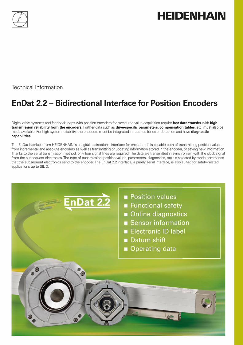
DR. JOHANNES HEIDENHAIN GmbH develops and manufactures linear and angle encoders as well as rotary encoders with EnDat interface in a large range of variants for a wide range of applications. HEIDENHAIN products are used in high-precision machine tools as well as in plants for the production and processing of electronic components.
The EnDat interface provides everything needed to reduce system cost and at the same time improve your technical standard. Extensive diagnostic possibilities, the support of safety strategies and the capability of storing operating and plant conditions in the encoder support state-of-the-art machine designs and ensure high quality and availability.
Cost optimization
• A single interface for all absolute and incremental encoders
• Simple subsequent electronics with EnDat receiver chip and standard components
• Simpler, more economical voltage supply, since remote sensing is not required
• Simple connection technology: standard plug connections (M12, 8-pin), simple shielded standard cables and low wiring complexity
Miniature connecting element, M12, 8-pin
Simple connection technology, 8-wire cable, single shielding
Integrated interpolation and position value formation, temperature measurement
Connecting element, e.g. M12, D-sub
Voltage supply without remote sensing(UP = 3.6 to 5.25 V or
3.6 to 14 V)
Simple subsequent electronics with EnDat 2.2 receiver chip (“EnDat master”)
* For parallel voltage supply lines or battery buffering
Benefi ts of the EnDat interface
Further
information:
For further information on implementing EnDat or additional documents, see www.endat.de
• Only one cable with HMC 6: the Hybrid Motor Cable contains the lines for the encoder, the motor and the brake
• Small motor or system dimensions through compact connecting elements
• No cost for additional sensors and wiring: EnDat 2.2 transmits additional data (limit switch, temperature, etc.)
• Faster confi guration during installation: Datum shifting through offsetting by a value in the encoder
Improved quality
• Higher system accuracy through specifi c optimization in the encoder
• High contouring accuracy, especially for CNC machine tools: Position value formation in the encoder enables shorter cycle times without affecting the computing time of the CNC
Higher availability
• Automatic commissioning of the system axis possible: all necessary information can be stored in the encoder (electronic ID label)
• High system reliability through purely digital data transmission
• Diagnostics of the encoders through monitoring messages and warnings that can be evaluated in the subsequent electronics
• High transmission reliability through cyclic redundancy checking
Safety system
• EnDat 2.2 was conceived for safety-related machine designs up to SIL 3
• Two independent position values for error detection
• Two independent error messages• Checksums and acknowledgments• Forced dynamic sampling of error
messages and CRC formation by subsequent electronics
Support for state-of-the-art machine
designs
• Suitable for direct drive technology thanks to high resolution, short cycle times and commutation information
• Cyclic sampling every 25 µs with full “read and write” mode
• Position values available in the subsequent electronics after only approx. 10 µs
• Online diagnostics allow planning of machine operation and support the service technician on site
• Plant and operating statuses can be stored in the encoder
3
– The bidirectional interface
Interface EnDat serial bidirectional
Data transfer Position values, parameters and additional data
Data input Differential line receiver according to EIA standard RS 485 for the signals CLOCK, CLOCK, DATA and DATA
Data output Differential line driver according to EIA standard RS 485 for DATA and DATA signals
Position values Increasing for traverse in the arrow direction (see "Mating dimensions of encoders")
Incremental signals Depends on encoder 1 VPP, TTL, HTL (see the respective incremental signals)
The EnDat interface is a digital, bidirectional interface for encoders. It is capable both of transmitting position values as well as transmitting or updating information stored in the encoder, or saving new information. Thanks to the serial transmission method, only four signal lines are required. The data is transmitted in synchronism with the clock signal from the subsequent electronics. The type of transmission (position values, parameters, diagnostics, etc.) is selected by mode commands that the subsequent electronics send to the encoder. Some functions are available only with EnDat 2.2 mode commands.
History and compatibility
The EnDat 2.1 interface, which has been available since the mid-1990s, has now been expanded to the EnDat 2.2 version (recommended for new applications). EnDat 2.2 is compatible in its communica-tion, command set and time conditions with version 2.1, but also offers signifi cant advantages. It makes it possible, for example, to transfer additional data (e.g. sensor value, diagnostics) with the position value without sending a separate request for it. This makes it possible to support additional encoder types (e.g., battery backup, incremental encoders). The interface protocol was expanded and the time conditions (clock frequency, processing time, recovery time) were optimized.
Supported encoder types
The following encoder types are currently supported with the EnDat 2.2 interface (readable from the memory area of the encoder):• Incremental linear encoder • Absolute linear encoder • Rotational incremental singleturn
encoder• Rotational absolute singleturn encoder • Multiturn rotary encoder • Multiturn rotary encoder with battery
bufferIn some cases, parameters must be interpreted differently for the various encoder types (see EnDat Specifi cations) or EnDat additional data must be processed (e.g. incremental or battery-buffered encoders).
Order designations
The order designations defi ne the central specifi cations and give information about:• Typical power supply range• Command set• Availability of incremental signals• Maximum clock frequencyThe second character of the order designation identifi es the interface generation. For encoders of the current generation, the ordering designation can be read from the encoder memory.
Incremental signals
Some encoders also provide incremental signals. These are usually used to increase the resolution of the position value, or to serve a second subsequent electronics unit. Current generations of encoders have a high internal resolution, and therefore no longer need to provide incremental signals. The order designation indicates whether an encoder outputs incremental signals:• EnDat 01 With 1 VPP incremental signals• EnDat H With HTL incremental signals• EnDatT With TTL incremental signals• EnDat21 Without incremental signals• EnDat02 With 1 VPP incremental signals• EnDat22 Without incremental signals
Note on EnDat01/02:The signal period is stored in the encoder memory.
Voltage supply
The typical voltage supply of the encoders depends on the interface:
EnDat01EnDat21
5 V ±0.25 V
EnDat02EnDat22
3.6 V to 5.25 V or 14 V
EnDatH 10 V to 30 V
EnDatT 4.75 V to 30 V
Exceptions are documented in the Specifi cations.
Command set
The command set describes the available mode commands, which defi ne the exchange of information between the encoder and the subsequent electronics. The EnDat 2.2 command set includes all EnDat 2.1 mode commands. In addition, EnDat 2.2 permits further mode commands for the selection of additional data, and makes memory accesses possible even in a closed control loop. When a mode command from the EnDat 2.2 command set is sent to an encoder that supports only the EnDat 2.1 command set, it results in an error message. The supported command set is stored in the encoder’s memory area:• EnDat01/21/H/T Command set 2.1
or 2.2• EnDat02/22 Command set 2.2
4
Cab
le len
gth
in
m
Clock frequency in kHzEnDat 2.1; EnDat 2.2 without propagation-delay compensation
EnDat 2.2 with propagation delay compensation (by the EnDat master)
Under certain conditions, cable lengths up to 300 m are possible after consultation with HEIDENHAIN
Additional data
Depending on the type of transmission (selection via MRS code), one or two additional data can be appended to the position value. The additional data supported by the respective encoder are saved in the encoder parameters.The additional data includes:
Status information, addresses and data• WRN – warnings• RM – reference mark• Busy – parameter request
Additional data 1• Diagnostics • Position value 2 • Memory parameters • MRS-code acknowledgment • Test values • Temperature • Additional sensors
Additional data 2• Commutation• Acceleration• Limit position signals• Asynchronous position value • Operating status error sources • Timestamp
Clock frequency
The clock frequency is variable between 100 kHz and 2 MHz, depending on the cable length (max. 150 m). With propagation-delay compensation in the subsequent electronics, either clock frequencies up to 16 MHz are possible or cable lengths up to 100 m. For EnDat encoders with order designation EnDat x2, the maximum clock frequency is stored in the encoder memory. For all other encoders, the maximum clock frequency is 2 MHz. Propagation-delay compensation is provided only for order designations EnDat 21 and EnDat 22; for EnDat 02, see the note below.
EnDat01EnDatTEnDatH
2 MHz (see diagram titled “Without delay compensation”)
EnDat21 2 MHz
EnDat02 2 MHz or 8 MHz or 16 MHz (see note)
EnDat22 8 MHz or 16 MHz
Transmission frequencies up to 16 MHz in combination with large cable lengths place high technological demands on the cable. The adapter cable connected directly to the encoder must not be longer than 20 m for reasons of transmission technology. Greater cable lengths can be realized with an adapter cable no longer than 6 m and an extension cable. As a rule, the entire transmission path must be designed for the respective clock frequency.
Note on EnDat02EnDat02 encoders can feature a pluggable cable assembly. In choosing the version of the adapter cable, the customer also decides whether the encoder will be operated with incremental signals or without them. This also affects the maximum possible clock frequency. For adapter cables with incremental signals, the clock frequency is limited to 2 MHz; see also EnDat01. For adapter cables without incremental signals the clock frequency can be up to 16 MHz. The exact values are stored in the encoder’s memory.
Position values
The position value can be transmitted with or without additional data. It is not transmitted to the subsequent electronics until after the calculation time tcal has passed. The computing time is determined for the highest clock frequency allowed for the encoder, but at maximum 8 MHz.
Only the required number of bits is transferred for the position value. The bit number depends on the respective encoder and can be read out from the encoder for automatic parameterization.
Typical operating modes
Operating mode EnDat 2.1: This mode is for encoders that provide additional incremental signals. The absolute position is read out once simultaneously with the incremental position and both are used to calculate the position value. Otherwise, the position value in the control loop is formed on the basis of the incremental signals. Only EnDat 2.1 mode commands are used.
Operating mode EnDat 2.2: This mode is for purely serial encoders. The position value is read out from the encoder in each control cycle. EnDat 2.2 mode commands are typically used to read out the position value. EnDat 2.1 mode commands are typically used to read and write parameters after switch-on.
In the EnDat 2.2 interface, additional data can be requested in the closed control loop in addition to the position, and functions can be executed (for example, read/write parameters, reset error messages, etc.).
5
Absolute encoder Subsequent electronics
1 VPP A*)
»PP B*)
Operating parameters
Operating status
Parameters of the OEM
Parameters of the encoder manufacturer for
EnDat 2.1 EnDat 2.2
*) Depending on device
Absolute position value En
Dat
inte
rfac
e
Incremental signals *)
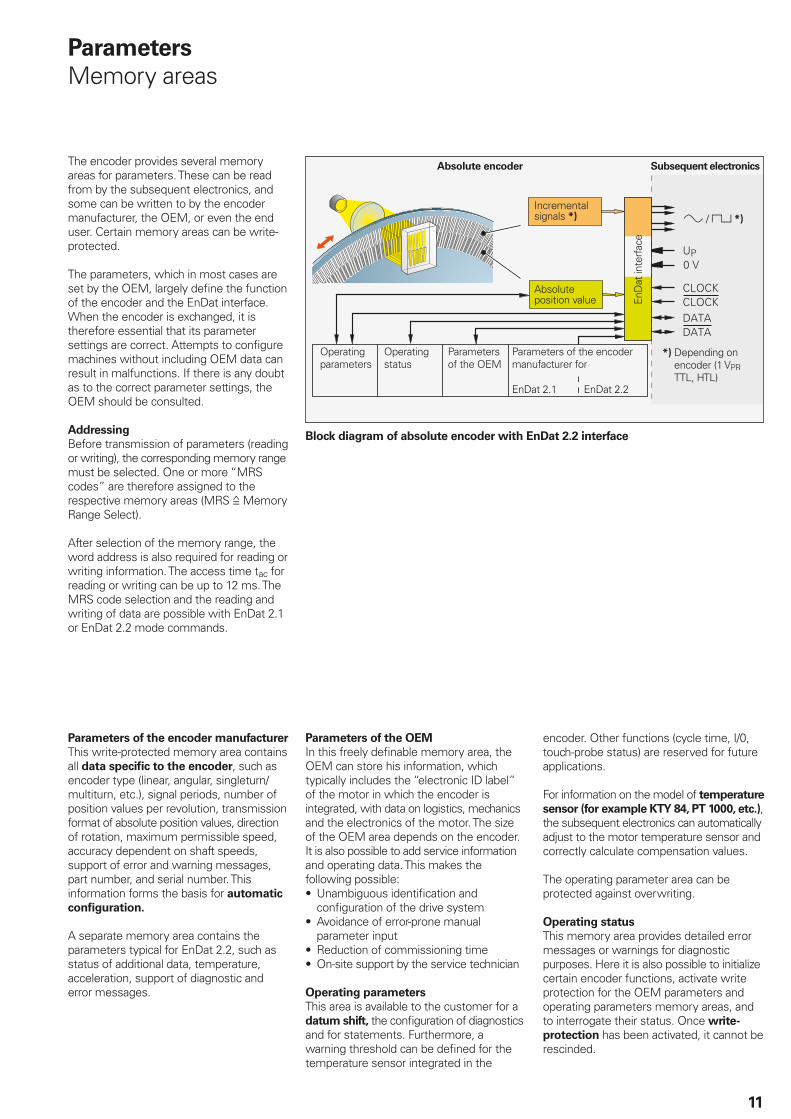
Memory areas
The encoder provides several memory areas for parameters. These can be read from by the subsequent electronics, and some can be written to by the encoder manufacturer, the OEM, or even the end user. The parameter data are stored in a permanent memory. This memory allows only a limited number of write accesses and is not designed for the cyclic storage of data. Certain storage areas can be secured with a write-protect (resettable only by the encoder manufacturer).
Parameters are saved in various memory areas, e.g.:• Encoder-specifi c information• Information of the OEM (e.g. “electronic
ID label” of the motor)• Operating parameters (datum shift,
instruction, etc.)• Operating status (alarms or warnings)
Monitoring and diagnostic functions of the EnDat interface make a detailed inspection of the encoder possible.• Error messages• Warnings• Online diagnostics based on valuation
numbers (EnDat 2.2)• Mounting interface
Input circuitry of subsequent
electronics
Dimensioning
IC1 = RS 485 differential line receiver and driver
Z0 = 120
Encoder Subsequent electronics
1 VPP
Functional safety—basic principle
EnDat 2.2 strictly supports the use of encoders in safety-related applications. The standards DIN EN ISO 13 849-1 (successor to EN 954-1) as well as EN 61 508 and EN 61 800-5-2 are used as basis. These standards describe the assessment of safety-related systems, for example based on the failure probabilities of integrated components and subsystems. The modular approach helps manufacturers of safety-related systems to implement their complete systems, because they can begin with prequalifi ed subsystems.
Data transfer
Incremental signals
Depending on the encoder (e.g. 1 VPP)
Further
information:
“Functional Safety” under www.endat.de
Further
information:
FAQ: RS-485 Transceiver at www.endat.de
6
A clock pulse (CLOCK) is provided by the subsequent electronics to synchronize the data transmission. When not transmitting, the clock signal is on high level.
Clock frequency and cable length
Without propagation-delay compensation, the clock frequency is variable between 100 kHz and 2 MHz, depending on the cable length. Because particularly in the case of large cable lengths and higher clock frequencies, the signal propagation time takes on magnitudes disturbing to the unambiguous assignment of data, it can be determined and compensated in a compensation run. This propagation-delay
compensation in the subsequent electronics make clock frequencies up to
16 MHz possible for cable lengths up to 100 m (fCLK 8 MHz). The maximum clock frequency is mainly determined by the cables and connecting elements used. To ensure proper function, use original HEIDENHAIN cables for clock frequencies over 2 MHz.
The permissible clock frequencies indicated in the diagrams apply for an on-off ratio of
the clock of 1:1. This means that the HIGH and LOW levels are equally long.
At a different on-off ratio of the clock, the theoretical clock frequency is calculated from fc =
Determining the propagation time
The signal propagation time can be ascertained through the EnDat master and is the basis for propagation-delay compensation. After every change in the transmission line hardware, the propa-gation time must be ascertained—preferably automatically after every power interruption.
Clock frequency
Clock frequency in kHz
Cab
le len
gth
in
m
Clock on-off ratio
Clock
12tmin
Data transfer
Under certain conditions, cable lengths up to 300 m are possible after consultation with HEIDENHAIN.
EnDat 2.1; EnDat 2.2 without propagation-delay compensation
EnDat 2.2 with propagation delay compensation (by the EnDat master)
7
Transmitted data are identifi ed as either position values, position values with additional data, or parameters. The type of information to be transmitted is selected by mode commands. Mode commands defi ne the content of the transmitted information. Every mode command consists of three bits. To ensure reliable transmission, every bit is transmitted redundantly (inverted or double). If the encoder detects an incorrect mode transmission, it transmits an error message. The EnDat 2.2 interface can also transfer parameter values in the additional data together with the position value. This makes the current position values constantly available for the control loop, even during a parameter request.
Mode bit
No. Mode command M2 M1 M0 (M2) (M1) (M0)
1 Encoder send position values
En
Dat
2.1
co
mm
an
d s
et4
)
En
Dat
2.2
co
mm
an
d s
et3
)
0 0 0 1 1 1
2 Selection of memory area 0 0 1 1 1 0
3 Encoder receive parameters 0 1 1 1 0 0
4 Encoder send parameters 1 0 0 0 1 1
5 Encoder receive reset 1 0 1 0 1 0
6 Encoder send test values 0 1 0 1 0 1
7 Encoder receive test command 1 1 0 0 0 1
8 Encoder send position value with additional data
1 1 1 0 0 0
9 Encoder send position value and receive selection of memory area 1)
0 0 1 0 0 1
10 Encoder send position value and receive parameter 1)
0 1 1 0 1 1
11 Encoder send position value and send parameter 1)
1 0 0 1 0 0
12 Encoder send position value and receive error reset 1)
1 0 1 1 0 1
13 Encoder send position value and receive test command 1)
1 1 0 1 1 0
14 Encoder receive communication command 2)
0 1 0 0 1 0
1) Selected additional data are also transferred2) Reserved for encoders that do not support the safety system3) The EnDat 2.2 command set includes the EnDat 2.1 command set4) These commands do not support the reduced recovery time
For EnDat-2.1 and EnDat-2.2 mode commands, encoders sometimes show different processing times for position values tcal (see the brochure Linear Encoders for Numerically Controlled Machine Tools – Specifi cations). If the incremental signals are evaluated for axis control, then the EnDat 2.1 mode commands should be used. Only in this manner can an active error message be transmitted synchronously with the currently requested position value. EnDat 2.1 mode commands should not be used for purely serial position-value transfer for axis control.
Selecting the transmission type
8
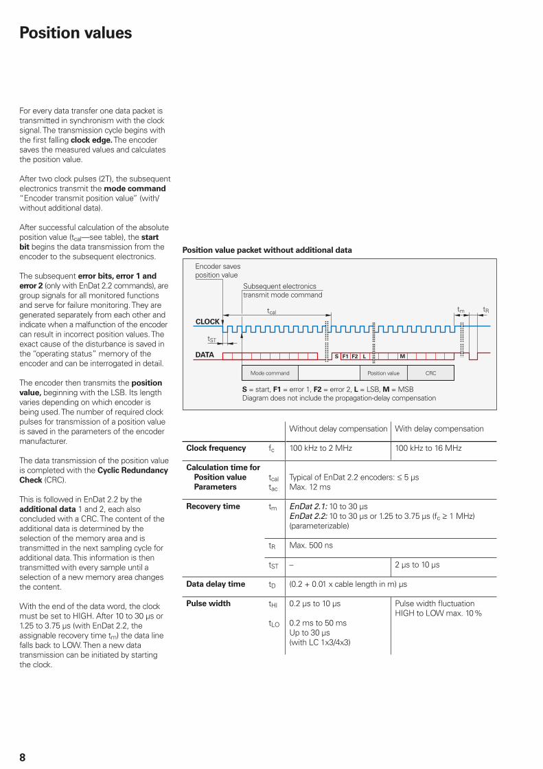
For every data transfer one data packet is transmitted in synchronism with the clock signal. The transmission cycle begins with the fi rst falling clock edge. The encoder saves the measured values and calculates the position value.
After two clock pulses (2T), the subsequent electronics transmit the mode command “Encoder transmit position value” (with/without additional data).
After successful calculation of the absolute position value (tcal—see table), the start
bit begins the data transmission from the encoder to the subsequent electronics.
The subsequent error bits, error 1 and
error 2 (only with EnDat 2.2 commands), are group signals for all monitored functions and serve for failure monitoring. They are generated separately from each other and indicate when a malfunction of the encoder can result in incorrect position values. The exact cause of the disturbance is saved in the “operating status” memory of the encoder and can be interrogated in detail.
The encoder then transmits the position
value, beginning with the LSB. Its length varies depending on which encoder is being used. The number of required clock pulses for transmission of a position value is saved in the parameters of the encoder manufacturer.
The data transmission of the position value is completed with the Cyclic Redundancy
Check (CRC).
This is followed in EnDat 2.2 by the additional data 1 and 2, each also concluded with a CRC. The content of the additional data is determined by the selection of the memory area and is transmitted in the next sampling cycle for additional data. This information is then transmitted with every sample until a selection of a new memory area changes the content.
With the end of the data word, the clock must be set to HIGH. After 10 to 30 µs or 1.25 to 3.75 µs (with EnDat 2.2, the assignable recovery time tm) the data line falls back to LOW. Then a new data transmission can be initiated by starting the clock.
Position value packet without additional data
Encoder saves position value
Subsequent electronics transmit mode command
Mode command Position value CRC
S = start, F1 = error 1, F2 = error 2, L = LSB, M = MSBDiagram does not include the propagation-delay compensation
Without delay compensation With delay compensation
Clock frequency fc 100 kHz to 2 MHz 100 kHz to 16 MHz
Calculation time for
Position value
Parameters
tcaltac
Typical of EnDat 2.2 encoders: 5 µsMax. 12 ms
Recovery time tm EnDat 2.1: 10 to 30 µsEnDat 2.2: 10 to 30 µs or 1.25 to 3.75 µs (fc 1 MHz) (parameterizable)
tR Max. 500 ns
tST – 2 µs to 10 µs
Data delay time tD (0.2 + 0.01 x cable length in m) µs
Pulse width tHI
tLO
0.2 µs to 10 µs
0.2 ms to 50 msUp to 30 µs (with LC 1x3/4x3)
Pulse width fl uctuation HIGH to LOW max. 10 %
Position values
9
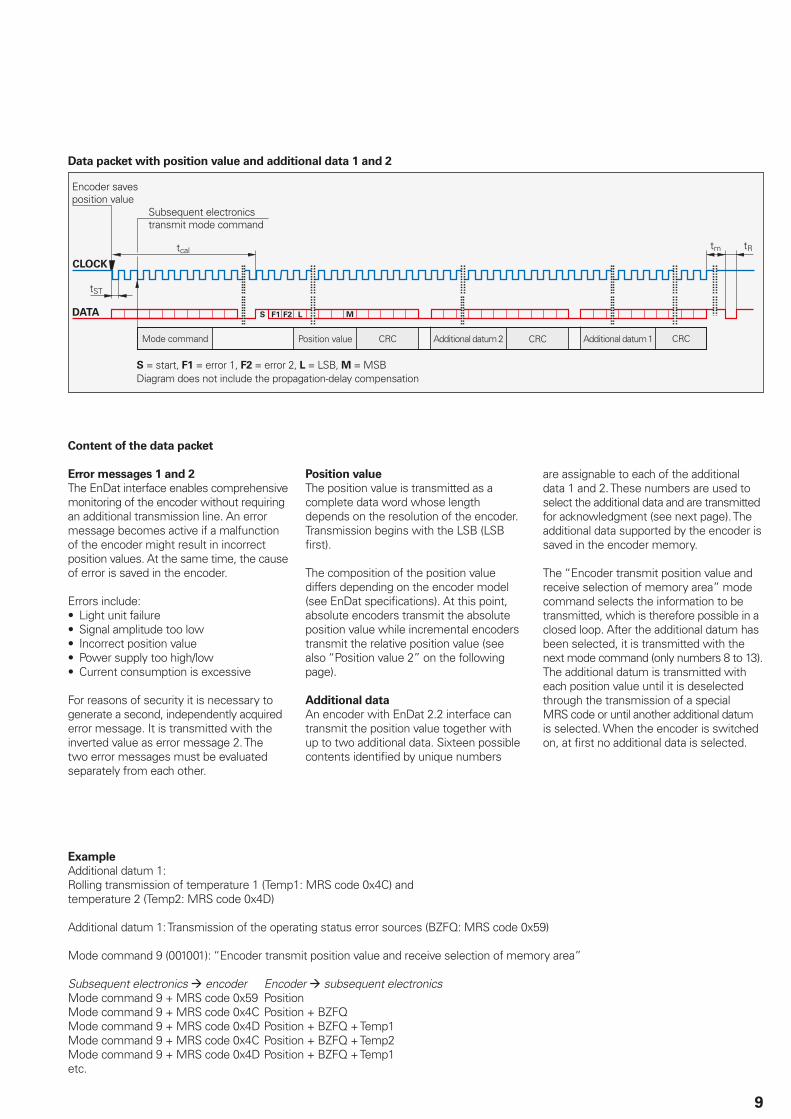
Data packet with position value and additional data 1 and 2
Encoder saves position value
Subsequent electronics transmit mode command
Mode command Position value CRC Additional datum 2 Additional datum 1CRC CRC
S = start, F1 = error 1, F2 = error 2, L = LSB, M = MSBDiagram does not include the propagation-delay compensation
Content of the data packet
Error messages 1 and 2
The EnDat interface enables comprehensive monitoring of the encoder without requiring an additional transmission line. An error message becomes active if a malfunction of the encoder might result in incorrect position values. At the same time, the cause of error is saved in the encoder.
Errors include:• Light unit failure• Signal amplitude too low• Incorrect position value• Power supply too high/low• Current consumption is excessive
For reasons of security it is necessary to generate a second, independently acquired error message. It is transmitted with the inverted value as error message 2. The two error messages must be evaluated separately from each other.
Position value
The position value is transmitted as a complete data word whose length depends on the resolution of the encoder. Transmission begins with the LSB (LSB fi rst).
The composition of the position value differs depending on the encoder model (see EnDat specifi cations). At this point, absolute encoders transmit the absolute position value while incremental encoders transmit the relative position value (see also “Position value 2” on the following page).
Additional data
An encoder with EnDat 2.2 interface can transmit the position value together with up to two additional data. Sixteen possible contents identifi ed by unique numbers
are assignable to each of the additional data 1 and 2. These numbers are used to select the additional data and are transmitted for acknowledgment (see next page). The additional data supported by the encoder is saved in the encoder memory.
The “Encoder transmit position value and receive selection of memory area” mode command selects the information to be transmitted, which is therefore possible in a closed loop. After the additional datum has been selected, it is transmitted with the next mode command (only numbers 8 to 13). The additional datum is transmitted with each position value until it is deselected through the transmission of a special MRS code or until another additional datum is selected. When the encoder is switched on, at fi rst no additional data is selected.
Example
Additional datum 1:Rolling transmission of temperature 1 (Temp1: MRS code 0x4C) and temperature 2 (Temp2: MRS code 0x4D)
Additional datum 1: Transmission of the operating status error sources (BZFQ: MRS code 0x59)
Mode command 9 (001001): “Encoder transmit position value and receive selection of memory area”
Subsequent electronics encoder Encoder subsequent electronicsMode command 9 + MRS code 0x59 PositionMode command 9 + MRS code 0x4C Position + BZFQMode command 9 + MRS code 0x4D Position + BZFQ + Temp1Mode command 9 + MRS code 0x4C Position + BZFQ + Temp2Mode command 9 + MRS code 0x4D Position + BZFQ + Temp1etc.
10
Status data
WRN – warnings
This collective bit indicates whether certain tolerance limits of the encoder have been reached or exceeded, for example rotational speed or light source control reserve, without necessarily indicating an incorrect position value. This function makes it possible to issue preventive warnings in order to minimize idle time. The cause of the warning is stored in the encoder memory. The error messages and warnings supported by the respective encoder are saved in the “parameters of the encoder manufacturer” memory area.
RM – reference mark
The RM bit indicates whether the reference run has been completed. In incremental systems, this is required in order to establish the absolute reference to the machine reference system. The absolute position value can then be read from the additional data 1. On absolute encoders, the RM bit is always on HIGH.
Busy – parameter request
When LOW, the busy bit indicates that a parameter request (read/write) is possible. If a request is being processed (HIGH), the encoder memory must not be accessed.
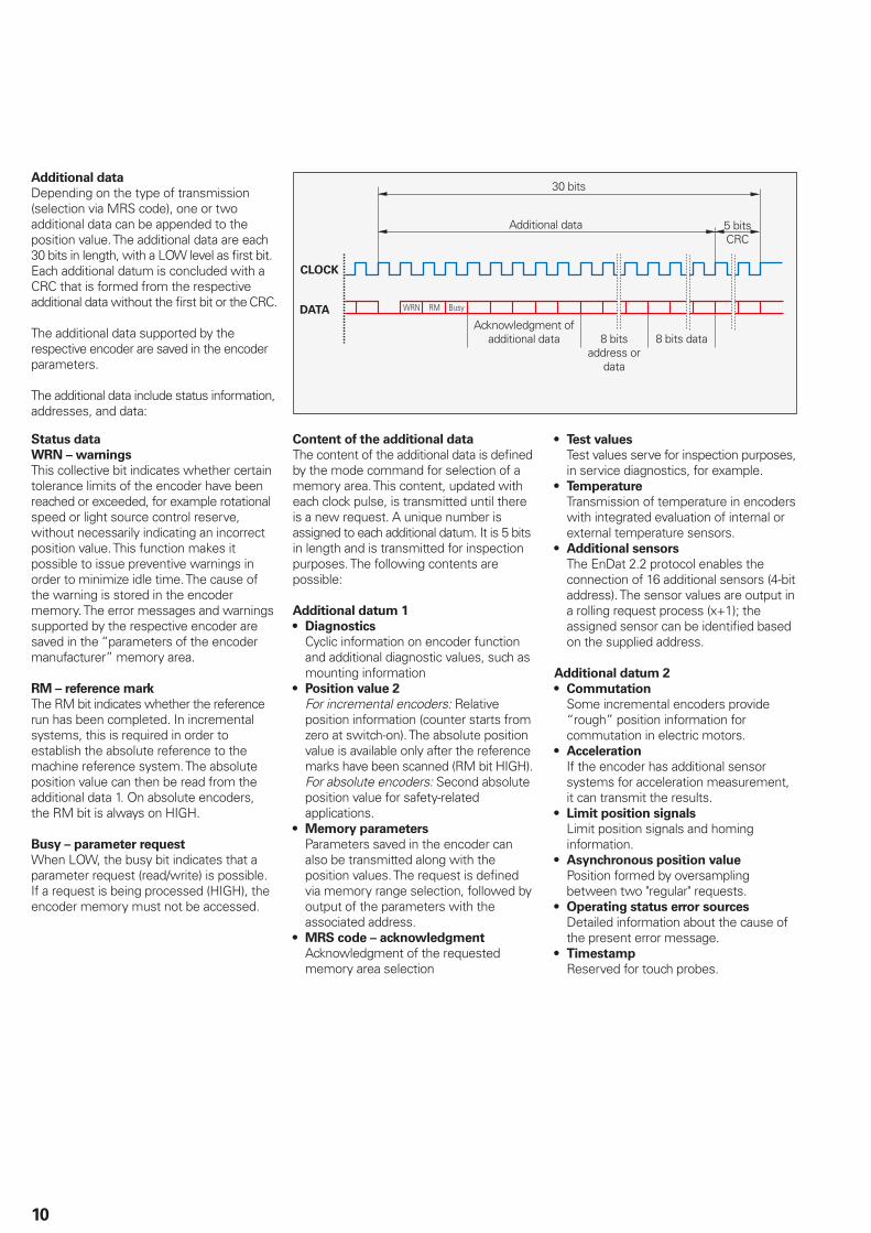
Content of the additional data
The content of the additional data is defi ned by the mode command for selection of a memory area. This content, updated with each clock pulse, is transmitted until there is a new request. A unique number is assigned to each additional datum. It is 5 bits in length and is transmitted for inspection purposes. The following contents are possible:
Additional datum 1
• Diagnostics
Cyclic information on encoder function and additional diagnostic values, such as mounting information
• Position value 2
For incremental encoders: Relative position information (counter starts from zero at switch-on). The absolute position value is available only after the reference marks have been scanned (RM bit HIGH). For absolute encoders: Second absolute position value for safety-related applications.
• Memory parameters
Parameters saved in the encoder can also be transmitted along with the position values. The request is defi ned via memory range selection, followed by output of the parameters with the associated address.
• MRS code – acknowledgment
Acknowledgment of the requested memory area selection
• Test values
Test values serve for inspection purposes, in service diagnostics, for example.
• Temperature
Transmission of temperature in encoders with integrated evaluation of internal or external temperature sensors.
• Additional sensors The EnDat 2.2 protocol enables the connection of 16 additional sensors (4-bit address). The sensor values are output in a rolling request process (x+1); the assigned sensor can be identifi ed based on the supplied address.
Additional datum 2
• Commutation
Some incremental encoders provide “rough” position information for commutation in electric motors.
• Acceleration
If the encoder has additional sensor systems for acceleration measurement, it can transmit the results.
• Limit position signals
Limit position signals and homing information.
• Asynchronous position value
Position formed by oversampling between two "regular" requests.
• Operating status error sources
Detailed information about the cause of the present error message.
• Timestamp
Reserved for touch probes.
30 bits
Additional data 5 bitsCRC
Acknowledgment of additional data 8 bits
address or data
8 bits data
Additional data
Depending on the type of transmission (selection via MRS code), one or two additional data can be appended to the position value. The additional data are each 30 bits in length, with a LOW level as fi rst bit. Each additional datum is concluded with a CRC that is formed from the respective additional data without the fi rst bit or the CRC.
The additional data supported by the respective encoder are saved in the encoder parameters.
The additional data include status information, addresses, and data:
11
The encoder provides several memory areas for parameters. These can be read from by the subsequent electronics, and some can be written to by the encoder manufacturer, the OEM, or even the end user. Certain memory areas can be write-protected.
The parameters, which in most cases are set by the OEM, largely defi ne the function of the encoder and the EnDat interface. When the encoder is exchanged, it is therefore essential that its parameter settings are correct. Attempts to confi gure machines without including OEM data can result in malfunctions. If there is any doubt as to the correct parameter settings, the OEM should be consulted.
Addressing
Before transmission of parameters (reading or writing), the corresponding memory range must be selected. One or more “MRS codes” are therefore assigned to the respective memory areas (MRS Memory Range Select).
After selection of the memory range, the word address is also required for reading or writing information. The access time tac for reading or writing can be up to 12 ms. The MRS code selection and the reading and writing of data are possible with EnDat 2.1 or EnDat 2.2 mode commands.
Block diagram of absolute encoder with EnDat 2.2 interface
Parameters of the encoder manufacturer
This write-protected memory area contains all data specifi c to the encoder, such as encoder type (linear, angular, singleturn/multiturn, etc.), signal periods, number of position values per revolution, transmission format of absolute position values, direction of rotation, maximum permissible speed, accuracy dependent on shaft speeds, support of error and warning messages, part number, and serial number. This information forms the basis for automatic
confi guration.
A separate memory area contains the parameters typical for EnDat 2.2, such as status of additional data, temperature, acceleration, support of diagnostic and error messages.
Parameters of the OEM
In this freely defi nable memory area, the OEM can store his information, which typically includes the “electronic ID label” of the motor in which the encoder is integrated, with data on logistics, mechanics and the electronics of the motor. The size of the OEM area depends on the encoder. It is also possible to add service information and operating data. This makes the following possible:• Unambiguous identifi cation and
confi guration of the drive system• Avoidance of error-prone manual
parameter input• Reduction of commissioning time• On-site support by the service technician
Operating parameters
This area is available to the customer for a datum shift, the confi guration of diagnostics and for statements. Furthermore, a warning threshold can be defi ned for the temperature sensor integrated in the
Parameters
Memory areas
encoder. Other functions (cycle time, I/0, touch-probe status) are reserved for future applications.
For information on the model of temperature
sensor (for example KTY 84, PT 1000, etc.), the subsequent electronics can automatically adjust to the motor temperature sensor and correctly calculate compensation values.
The operating parameter area can be protected against overwriting.
Operating status
This memory area provides detailed error messages or warnings for diagnostic purposes. Here it is also possible to initialize certain encoder functions, activate write protection for the OEM parameters and operating parameters memory areas, and to interrogate their status. Once write-
protection has been activated, it cannot be rescinded.
Absolute encoder Subsequent electronics
Absolute position value
Operating parameters
Operating status
Parameters of the OEM
Parameters of the encoder manufacturer for
EnDat 2.1 EnDat 2.2
EnD
at in
terf
ace
Incremental signals *)
*) Depending on encoder (1 VPP, TTL, HTL)
/ *)
12
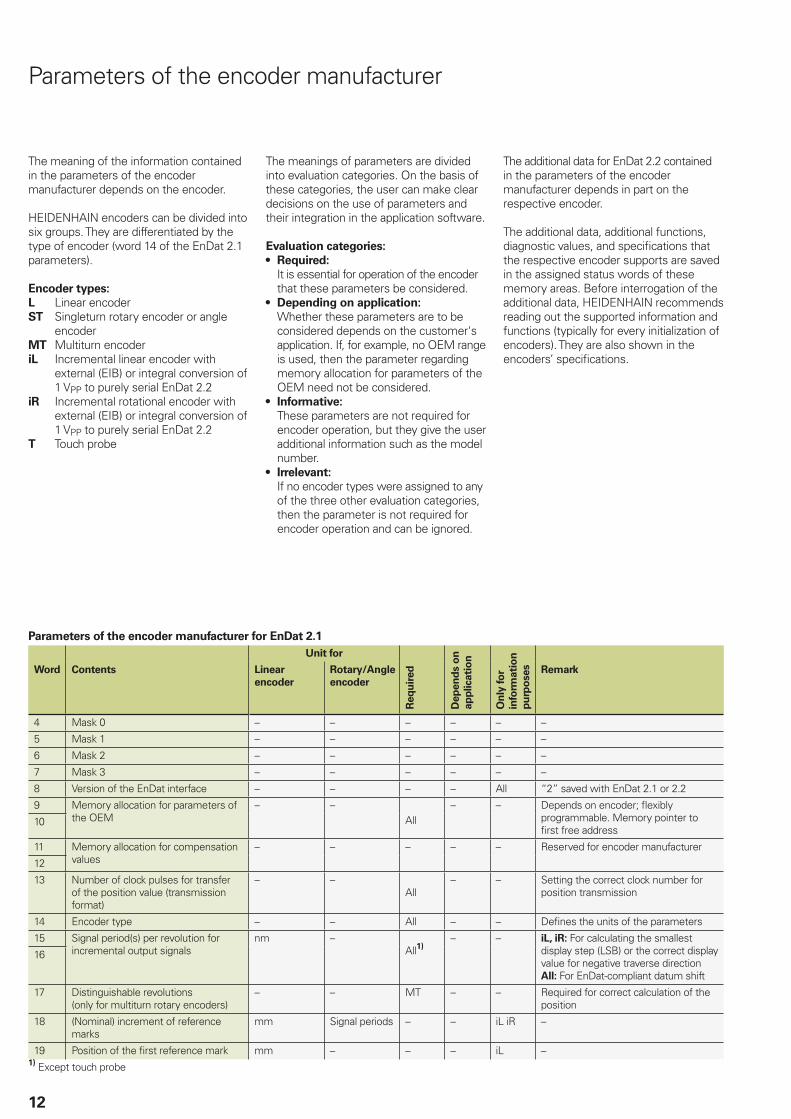
The meaning of the information contained in the parameters of the encoder manufacturer depends on the encoder.
HEIDENHAIN encoders can be divided into six groups. They are differentiated by the type of encoder (word 14 of the EnDat 2.1 parameters).
Encoder types:
L Linear encoderST Singleturn rotary encoder or angle
encoderMT Multiturn encoderiL Incremental linear encoder with
external (EIB) or integral conversion of 1 VPP to purely serial EnDat 2.2
iR Incremental rotational encoder with external (EIB) or integral conversion of 1 VPP to purely serial EnDat 2.2
T Touch probe
The meanings of parameters are divided into evaluation categories. On the basis of these categories, the user can make clear decisions on the use of parameters and their integration in the application software.
Evaluation categories:
• Required:
It is essential for operation of the encoder that these parameters be considered.
• Depending on application:
Whether these parameters are to be considered depends on the customer's application. If, for example, no OEM range is used, then the parameter regarding memory allocation for parameters of the OEM need not be considered.
• Informative:
These parameters are not required for encoder operation, but they give the user additional information such as the model number.
• Irrelevant:
If no encoder types were assigned to any of the three other evaluation categories, then the parameter is not required for encoder operation and can be ignored.
The additional data for EnDat 2.2 contained in the parameters of the encoder manufacturer depends in part on the respective encoder.
The additional data, additional functions, diagnostic values, and specifi cations that the respective encoder supports are saved in the assigned status words of these memory areas. Before interrogation of the additional data, HEIDENHAIN recommends reading out the supported information and functions (typically for every initialization of encoders). They are also shown in the encoders’ specifi cations.
Parameters of the encoder manufacturer
Parameters of the encoder manufacturer for EnDat 2.1
Unit for
Req
uir
ed
Dep
en
ds o
n
ap
plicati
on
On
ly fo
r
info
rmati
on
pu
rpo
ses
Word Contents Linear
encoder
Rotary/Angle
encoder
Remark
4 Mask 0 – – – – – –
5 Mask 1 – – – – – –
6 Mask 2 – – – – – –
7 Mask 3 – – – – – –
8 Version of the EnDat interface – – – – All “2” saved with EnDat 2.1 or 2.2
9 Memory allocation for parameters of the OEM
– –All
– – Depends on encoder; fl exibly programmable. Memory pointer to fi rst free address
10
11 Memory allocation for compensation values
– – – – – Reserved for encoder manufacturer
12
13 Number of clock pulses for transfer of the position value (transmission format)
– –All
– – Setting the correct clock number for position transmission
14 Encoder type – – All – – Defi nes the units of the parameters
15 Signal period(s) per revolution for incremental output signals
nm –All1)
– – iL, iR: For calculating the smallest display step (LSB) or the correct display value for negative traverse directionAll: For EnDat-compliant datum shift
16
17 Distinguishable revolutions(only for multiturn rotary encoders)
– – MT – – Required for correct calculation of the position
18 (Nominal) increment of reference marks
mm Signal periods – – iL iR –
19 Position of the fi rst reference mark mm – – – iL –1) Except touch probe
13
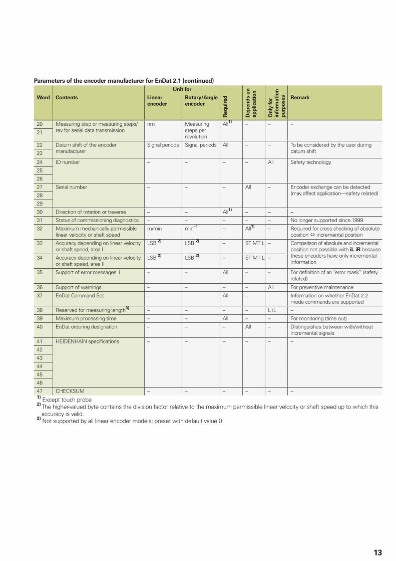
Parameters of the encoder manufacturer for EnDat 2.1 (continued)
Unit for
Req
uir
ed
Dep
en
ds o
n
ap
plicati
on
On
ly fo
r
info
rmati
on
pu
rpo
ses
Word Contents Linear
encoder
Rotary/Angle
encoder
Remark
20 Measuring step or measuring steps/rev for serial data transmission
nm Measuring steps per revolution
All1) – – –
21
22 Datum shift of the encoder manufacturer
Signal periods Signal periods All – – To be considered by the user during datum shift23
24 ID number – – – – All Safety technology
25
26
27 Serial number – – – All – Encoder exchange can be detected (may affect application—safety related)28
29
30 Direction of rotation or traverse – – All1) – – –
31 Status of commissioning diagnostics – – – – – No longer supported since 1999
32 Maximum mechanically permissible linear velocity or shaft speed
m/min min–1 – All1) – Required for cross checking of absolute position incremental position
33 Accuracy depending on linear velocity or shaft speed, area I
LSB 2) LSB 2) – ST MT L – Comparison of absolute and incremental position not possible with iL iR because these encoders have only incremental information
34 Accuracy depending on linear velocity or shaft speed, area II
LSB 2) LSB 2) – ST MT L –
35 Support of error messages 1 – – All – – For defi nition of an “error mask” (safety related)
36 Support of warnings – – – – All For preventive maintenance
37 EnDat Command Set – – All – – Information on whether EnDat 2.2 mode commands are supported
38 Reserved for measuring length3) – – – – L iL –
39 Maximum processing time – – All – – For monitoring (time out)
40 EnDat ordering designation – – – All – Distinguishes between with/without incremental signals
41 HEIDENHAIN specifi cations – – – – – –
42
43
44
45
46
47 CHECKSUM – – – – – –1) Except touch probe2) The higher-valued byte contains the division factor relative to the maximum permissible linear velocity or shaft speed up to which this
accuracy is valid.3) Not supported by all linear encoder models; preset with default value 0
14
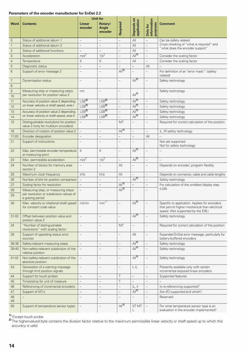
Parameters of the encoder manufacturer for EnDat 2.2
Unit for
Req
uir
ed
Dep
en
ds o
n
ap
plicati
on
On
ly fo
r
info
rmati
on
pu
rpo
ses
Word Contents Linear
encoder
Rotary/
Angle
encoder
Comment
0 Status of additional datum 1 – – – All – Can be safety related. Cross checking of “what is required” and “what does the encoder support”
1 Status of additional datum 2 – – – All –
2 Status of additional functions – – – All –
3 Acceleration m/s2 1/s2 – All1) – Consider the scaling factor
4 Temperature K K – All – Consider the scaling factor
5 Diagnostic status – – – – All –
6 Support of error message 2 – – All1) – – For defi nition of an “error mask”: (safety related)
7 Dynamization status – – – All1) – Safety technology
8
9 Measuring step or measuring steps per revolution for position value 2
nm – –All1)
– Safety technology
10
11 Accuracy of position value 2 depending on linear velocity or shaft speed, area I
LSB2) LSB2) – All1) – Safety technology
12 LSB2) LSB2) – All1) – Safety technology
13 Accuracy of position value 2 depending on linear velocity or shaft speed, area II
LSB2) LSB2) – All1) – Safety technology
14 LSB2) LSB2) – All1) – Safety technology
15 Distinguishable revolutions for position value 2 (only for multiturn encoders)
– – MT – – Required for correct calculation of the position
16 Direction of rotation of position value 2 – – All1) – – iL, iR safety technology
17-20 Encoder designation – – – – All –
21 Support of instructions – – – – – Not yet supportedNot for safety technology
22 Max. permissible encoder temperature at measuring point
K K – All1) – –
23 Max. permissible acceleration m/s2 1/s2 – All1) – –
24 Number of blocks for memory area section 2
– – All – – Depends on encoder; program fl exibly.
25 Maximum clock frequency kHz kHz All – – Depends on connector, cable and cable lengths
26 Number of bits for position comparison – – – All1) – Safety technology
27 Scaling factor for resolution – – All1) – – For calculation of the smallest display step (LSB)28 Measuring step, or measuring steps
per revolution or subdivision values of a grating period
– – All1) – –
29
30 Max. velocity or rotational shaft speed for constant code value
m/min min–1 – All1) – Specifi c to application. Applies for encoders that permit higher mechanical than electrical speed. (Not supported by the EIB.)
31-33 Offset between position value and position value 2
– – – All1) – Safety technology
34 “Number of distinguishable revolutions” with scaling factor
– – MT – – Required for correct calculation of the position
35 Support of operating status error sources
– – – All – Expanded EnDat error message, particularly for battery-buffered encoders
36-38 Safety-relevant measuring steps – – – All1) – Safety technology
39-40 Non-safety-relevant subdivision of the relative position
– – – All1) – Safety technology
41-42 Non-safety-relevant subdivision of the absolute position
– – – All1) – Safety technology
43 Generation of a warning message through limit position signals
– – – L iL – Presently available only with certain incremental exposed linear encoders
44 Support for touch probes – – T – – Supported features
45 Timestamp for unit of measure – – T – – –
46 Referencing of incremental encoders – – – iL, Ir – Is re-referencing supported?
47 Support of I/O's – – – All1) – Are I/O supported and which?
4849
– – – – – – Reserved
50 Support of temperature sensor types – – All1) ST MT L
– For what temperature sensor type is an evaluation in the encoder implemented?
1) Except touch probe2) The higher-valued byte contains the division factor relative to the maximum permissible linear velocity or shaft speed up to which this
accuracy is valid
15
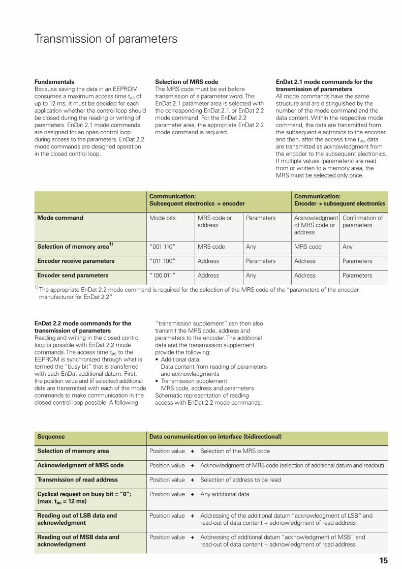
Transmission of parameters
Fundamentals
Because saving the data in an EEPROM consumes a maximum access time tac of up to 12 ms, it must be decided for each application whether the control loop should be closed during the reading or writing of parameters. EnDat 2.1 mode commands are designed for an open control loop during access to the parameters. EnDat 2.2 mode commands are designed operation in the closed control loop.
Selection of MRS code
The MRS code must be set before transmission of a parameter word. The EnDat 2.1 parameter area is selected with the corresponding EnDat 2.1. or EnDat 2.2 mode command. For the EnDat 2.2 parameter area, the appropriate EnDat 2.2 mode command is required.
Communication:
Subsequent electronics encoder
Communication:
Encoder subsequent electronics
Mode command Mode bits MRS code or address
Parameters Acknowledgment of MRS code or address
Confi rmation of parameters
Selection of memory area1) “001 110” MRS code Any MRS code Any
Encoder receive parameters “011 100” Address Parameters Address Parameters
Encoder send parameters “100 011” Address Any Address Parameters
1) The appropriate EnDat 2.2 mode command is required for the selection of the MRS code of the “parameters of the encoder manufacturer for EnDat 2.2“
EnDat 2.2 mode commands for the
transmission of parameters
Reading and writing in the closed control loop is possible with EnDat 2.2 mode commands. The access time tac to the EEPROM is synchronized through what is termed the “busy bit” that is transferred with each EnDat additional datum. First, the position value and (if selected) additional data are transmitted with each of the mode commands to make communication in the closed control loop possible. A following
Sequence Data communication on interface (bidirectional)
Selection of memory area Position value + Selection of the MRS code
Acknowledgment of MRS code Position value + Acknowledgment of MRS code (selection of additional datum and readout)
Transmission of read address Position value + Selection of address to be read
Cyclical request on busy bit = “0”;
(max. tac = 12 ms)
Position value + Any additional data
Reading out of LSB data and
acknowledgment
Position value + Addressing of the additional datum “acknowledgment of LSB“ and read-out of data content + acknowledgment of read address
Reading out of MSB data and
acknowledgment
Position value + Addressing of additional datum “acknowledgment of MSB“ and read-out of data content + acknowledgment of read address
“transmission supplement” can then also transmit the MRS code, address and parameters to the encoder. The additional data and the transmission supplement provide the following:• Additional data:
Data content from reading of parameters and acknowledgments
• Transmission supplement:MRS code, address and parameters
Schematic representation of reading access with EnDat 2.2 mode commands:
EnDat 2.1 mode commands for the
transmission of parameters
All mode commands have the same structure and are distinguished by the number of the mode command and the data content. Within the respective mode command, the data are transmitted from the subsequent electronics to the encoder and then, after the access time tac, data are transmitted as acknowledgment from the encoder to the subsequent electronics. If multiple values (parameters) are read from or written to a memory area, the MRS must be selected only once.
16
Diagnostics
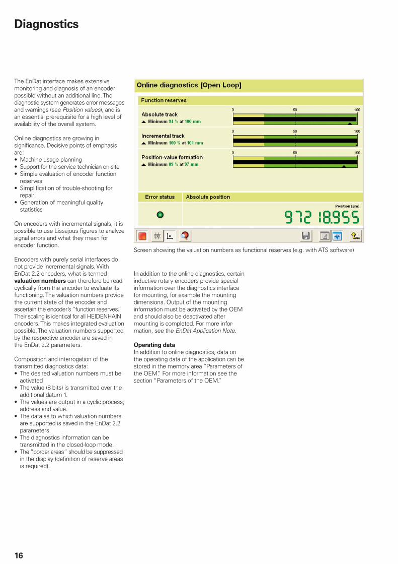
The EnDat interface makes extensive monitoring and diagnosis of an encoder possible without an additional line. The diagnostic system generates error messages and warnings (see Position values), and is an essential prerequisite for a high level of availability of the overall system.
Online diagnostics are growing in signifi cance. Decisive points of emphasis are:• Machine usage planning • Support for the service technician on-site• Simple evaluation of encoder function
reserves• Simplifi cation of trouble-shooting for
repair• Generation of meaningful quality
statistics
On encoders with incremental signals, it is possible to use Lissajous fi gures to analyze signal errors and what they mean for encoder function.
Encoders with purely serial interfaces do not provide incremental signals. With EnDat 2.2 encoders, what is termed valuation numbers can therefore be read cyclically from the encoder to evaluate its functioning. The valuation numbers provide the current state of the encoder and ascertain the encoder’s “function reserves.” Their scaling is identical for all HEIDENHAIN encoders. This makes integrated evaluation possible. The valuation numbers supported by the respective encoder are saved in the EnDat 2.2 parameters.
Composition and interrogation of the transmitted diagnostics data:• The desired valuation numbers must be
activated• The value (8 bits) is transmitted over the
additional datum 1.• The values are output in a cyclic process;
address and value.• The data as to which valuation numbers
are supported is saved in the EnDat 2.2 parameters.
• The diagnostics information can be transmitted in the closed-loop mode.
• The “border areas” should be suppressed in the display (defi nition of reserve areas is required).
Screen showing the valuation numbers as functional reserves (e.g. with ATS software)
In addition to the online diagnostics, certain inductive rotary encoders provide special information over the diagnostics interface for mounting, for example the mounting dimensions. Output of the mounting information must be activated by the OEM and should also be deactivated after mounting is completed. For more infor-mation, see the EnDat Application Note.
Operating data
In addition to online diagnostics, data on the operating data of the application can be stored in the memory area “Parameters of the OEM.” For more information see the section “Parameters of the OEM.”
17
Confi guration
The EnDat interface makes it possible to set various functions regarding data transmission or the general operation of the encoder. The various EnDat words for setting functions are located in the “operating status” or “operating parameters” memory areas. The settings are normally saved and need only be made once.
Operating status
Function initialization
Recovery time:• 10 µs tm 30 µs selectable to
1.25 µs tm 3,75 µs (for mode commands no. 8 to 14 and fCLK > 1 MHz)
• Reduced recovery time is set when very short cycle times are to be attained.
Multiturn functions:• Make it possible to connect encoders
with a battery-buffered revolution counter
Reference pulse initialization:• Only with incremental encoders for
fi nding the optimal reference mark position
The following functions are reserved for future applications and therefore cannot yet be set:• Oversampling, diagnostics reset• EnDat 2.2 cyclic operation I/O, statuses of
touch probes, referencing of incremental encoders can be switched off
Write protection
The customer can write-protect the OEM parameters (“electronic ID label”) and/or the operating parameters individually (e.g. datum shift).
Operating parameters
Datum shift
This function is called “electronic datum setting” and enables the customer to fi t the encoder datum to the datum of the application.
Confi guration of diagnostics
This EnDat word activates the desired valuation numbers for transmission of diagnostic information.
Recommendation: All available valuation numbers should be activated to ensure the maximum depth of information on the encoder’s function reserves.
Address assignment and instructions
Reserved for future bus operation through the EnDat interface.
Threshold sensitivity to temperature
Specifi cation of a temperature threshold at which the encoder transmits a warning to the subsequent electronics. The temperature is derived from the encoder’s internal temperature sensor
Temperature sensor type or connected
temperature sensor type
For information on the model of tempe-
rature sensor (for example KTY 84,
PT 1000, etc.), the subsequent electronics can automatically adjust to the motor temperature sensor and correctly calculate compensation values. Future encoder generations allow an active switchover of evaluation of the connected temperature sensor type.
Cycle time
Setting the cycle time with which the higher-level control transmits EnDat requests. Reserved for future applications.
18
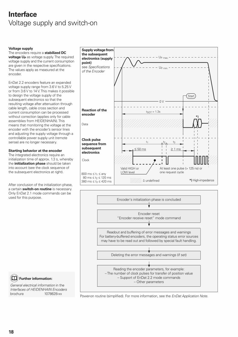
Voltage supply
The encoders require a stabilized DC
voltage UP as voltage supply. The required voltage supply and the current consumption are given in the respective specifi cations. The values apply as measured at the encoder.
EnDat 2.2 encoders feature an expanded voltage supply range from 3.6 V to 5.25 V or from 3.6 V to 14 V. This makes it possible to design the voltage supply of the subsequent electronics so that the resulting voltage after attenuation through cable length, cable cross section and current consumption can be processed without correction (applies only for cable assemblies from HEIDENHAIN). This means that monitoring the voltage at the encoder with the encoder’s sensor lines and adjusting the supply voltage through a controllable power supply unit (remote sense) are no longer necessary.
Starting behavior at the encoder
The integrated electronics require an initialization time of approx. 1.3 s, whereby the initialization phase should be taken into account (see the clock sequence of the subsequent electronics at right).
After conclusion of the initialization phase, a certain switch-on routine is necessary. Only EnDat 2.1 mode commands can be used for this purpose.
Supply voltage from
the subsequent
electronics (supply
point)
see Specifi cations of the Encoder
Reaction of the
encoder
Clock pulse
sequence from
subsequent
electronics
UP max.
UP min.
Start
undefi ned
Valid HIGH or LOW level
1 ms
At least one pulse (> 125 ns) or one request cycle
50 ms
*)High-impedance
Interface
Voltage supply and switch-on
Encoder's initialization phase is concluded
Encoder reset“Encoder receive reset” mode command
Readout and buffering of error messages and warningsFor battery-buffered encoders, the operating status error sources may have to be read out and followed by special fault handling.
Deleting the error messages and warnings (if set)
Reading the encoder parameters, for example:– The number of clock pulses for transfer of position value
– Support of EnDat 2.2 mode commands– Other parameters
Data
800 ms t1 any 80 ms t2 120 ms380 ms t3 420 ms
Clock
Power-on routine (simplifi ed). For more information, see the EnDat Application Note.
Further
information:
General electrical information in the Interfaces of HEIDENHAIN Encoders brochure 1078628-xx
19
HEIDENHAIN offers various aids for imple-menting the EnDat interface in subsequent electronics (see also “Implementation” section at www.endat.de):
EnDat Demotool software
The EnDat Demotool software requires a PWM 20 as hardware basis. The EnDat Demotool software supports you when implementing the EnDat interface:• Communication with EnDat encoders on
the basis of mode commands• Logging of EnDat command sequences• Provides a reference when integrating of
the EnDat master into the control loop
EnDat master
The EnDat master controls communication with EnDat encoders from HEIDENHAIN. It allows simple transmission of position data and additional data to the higher-level application. The EnDat master can be integrated by means of a micro controller (µC or SoC) or an FPGA (Field Programmable Gate Array) or ASIC.
The µC solutions are used if the intended clock frequencies are relatively low. Integration in an FPGA, ASIC or SoC is chosen primarily for high transmission frequencies with purely serial data transfer. Several variants are available for integration:• MAZeT: Diverse versions for FPGA• Texas Instruments: C2000, Sitara, etc.• Renesas: RZ/T1• Hilscher: nextX 90• HEIDENHAIN: Demo code for µC and
EIB 74x
EnDat error injector
The simulation of a faulty data transmission can be useful for test purposes. The EnDat error injector enables manipulation of an EnDat transmission in a closed loop. A special PWM 20 version forms the basis for the error injector.
Documentation
• EnDat Specifi cations• EnDat Application Note• EnDat Seminar• FAQ and implementation at
www.endat.de• Technical Information: EnDat • EnDat-Master at www.endat.de
Implementation of EnDat
Connecting elements
Encoders with EnDat 2.2 interface without incremental signals use mainly 8-pin M12 connecting elements, but also 9-pin M23. M12 connector technology is in wide use in industrial applications and has the following advantages:• Cost-effective connection technology• Smaller dimensions• Simpler cable feed through in machines• Thinner connecting cables ( 6 mm
instead of the previous 8 mm)• Higher reliability thanks to injection-coated
connection technology• Integrated lock mechanism as vibration
protection
Connection technology
Cable
Transmission frequencies up to 16 MHz in combination with large cable lengths place high technological demands on the cable. HEIDENHAIN cables are equal to this task, not least because of a cable construction conceived specifi cally for this application. We recommend using original HEIDENHAIN cables.
Further
information:
Brochure: Cables and Connectors for HEIDENHAIN Controls
Further
information:
HMC 6 Product Information
HMC 6
Single-cable solution for servo drives
Motors normally need two separate cables:• One cable for the motor encoder• One cable for the motor power supply
With its Hybrid Motor Cable HMC 6, HEIDENHAIN has integrated the encoder lines in the power cable. So now only one cable is needed between the motor and electrical cabinet.
������������ ��� ��������������� ��������������������������������������� �������������� �������������������� !��"�#����������
������ !���� ��!�
383942-28 · 5 · 09/2017 · H · Printed in Germany
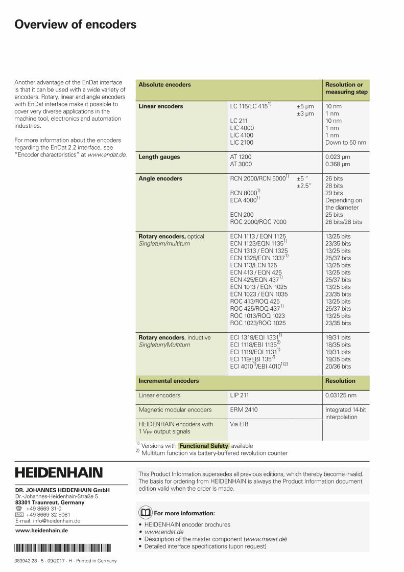
Another advantage of the EnDat interface is that it can be used with a wide variety of encoders. Rotary, linear and angle encoders with EnDat interface make it possible to cover very diverse applications in the machine tool, electronics and automation industries.
For more information about the encoders regarding the EnDat 2.2 interface, see “Encoder characteristics” at www.endat.de.
Overview of encoders
Absolute encoders Resolution or
measuring step
Linear encoders LC 115/LC 4151)
LC 211LIC 4000LIC 4100LIC 2100
±5 µm±3 µm
10 nm1 nm10 nm1 nm1 nmDown to 50 nm
Length gauges AT 1200AT 3000
0.023 µm0.368 µm
Angle encoders RCN 2000/RCN 50001)
RCN 80001)
ECA 40001)
ECN 200ROC 2000/ROC 7000
±5 “±2.5”
26 bits28 bits29 bitsDepending on the diameter25 bits26 bits/28 bits
Rotary encoders, opticalSingleturn/multiturn
ECN 1113 / EQN 1125ECN 1123/EQN 11351)
ECN 1313 / EQN 1325ECN 1325/EQN 13371)
ECN 113/ECN 125ECN 413 / EQN 425ECN 425/EQN 4371)
ECN 1013 / EQN 1025ECN 1023 / EQN 1035ROC 413/ROQ 425ROC 425/ROQ 4371)
ROC 1013/ROQ 1023ROC 1023/ROQ 1025
13/25 bits23/35 bits13/25 bits25/37 bits13/25 bits13/25 bits25/37 bits13/25 bits23/35 bits13/25 bits25/37 bits13/25 bits23/35 bits
Rotary encoders, inductiveSingleturn/Multiturn
ECI 1319/EQI 13311)
ECI 1118/EBI 11352)
ECI 1119/EQI 11311)
ECI 119/EBI 1352)
ECI 40101)/EBI 40101)2)
19/31 bits18/35 bits19/31 bits19/35 bits20/36 bits
Incremental encoders Resolution
Linear encoders LIP 211 0.03125 nm
Magnetic modular encoders ERM 2410 Integrated 14-bitinterpolation
HEIDENHAIN encoders with 1 VPP output signals
Via EIB
1) Versions with Functional Safety available2) Multiturn function via battery-buffered revolution counter
This Product Information supersedes all previous editions, which thereby become invalid. The basis for ordering from HEIDENHAIN is always the Product Information document edition valid when the order is made.
For more information:
• HEIDENHAIN encoder brochures• www.endat.de• Description of the master component (www.mazet.de)• Detailed interface specifi cations (upon request)